gasoline spark ignition 2015 - autelligence · figure 29: using vanes in a variable geometry turbo,...
TRANSCRIPT

tel: +45 2334 0705
e-mail: [email protected]
web: www.autelligence.com
By Bruce Morey
Gasoline spark ignition engines: trends and emerging technologies

Autelligence Copyright© 2015 Autelligence ApS. All rights reserved. Neither this publication nor any part of it may be reproduced, stored in a retrieval system, or transmitted in any form or by any means, electronic, mechanical, photocopying, recording or otherwise, without the prior permission of Autelligence ApS.
The authors of Autelligence ApS Research Reports are drawn from a wide range of professional and academic disciplines. All the information in the reports is verified to the best of the authors’ and the publisher’s ability, but neither can accept responsibility for loss arising from decisions based on these reports.

© Autelligence ApS 2015Gasoline spark ignition engines:
trends and emerging technologies
About the author
Bruce Morey
With over twenty-five years of experience in technology development, research and management,
Bruce Morey brings a unique perspective when looking at the future of automotive engineering. His
sixteen years in the defence industry exposed him to a number of forward-looking methodologies,
including scenario and contingency planning. His six years in automotive product development at Ford
Motor Company gave him an inside look at the day-to-day challenges and pressures of delivering quality
vehicles and engines that customers want to buy, at an affordable price to both customer and company.
His published articles have covered computer simulation in support of engine development, future fuels,
fuel cell vehicles, manufacturing, automotive engineering and product development. Mr. Morey is also
the author of two books, Automotive 2030 North America and Future Automotive Fuels and Energy, both
published by SAE International. Mr. Morey earned both Bachelors and Masters degrees in mechanical
engineering from the University of Michigan. Mr. Morey is a member of SAE International and the Society
of Manufacturing Engineers.
About the editor
Soren Sarstrup, Managing Editor
Soren Sarstrup has spent most of his career working in the automotive intelligence industry.
As founder and Managing Editor of Autelligence Ltd., he contributes extensive editorial and publishing
experience, a global network of contacts on both the OEM and supplier side, in-depth understanding of the
industry and the markets it operates in, hands-on sales and marketing experience, and, last but not least, a
long-standing passion for all things automotive.
1© Autelligence ApS 2015Gasoline spark ignition engines:
trends and emerging technologies
Table of contents
Table of contents
Chapter 1: Introduction . . . . . . . . . . . . . . . . . . . . . . . . . . . . . . . . . . . . . . . . . . . . . . . . . . . . . . . . . . . . . . . 5
Chapter 2: 21st-century concerns and the basic gasoline SI engine. . . . . . . . . . . . . . . . . . . . 6
2.1 The quest for a meaningful test. . . . . . . . . . . . . . . . . . . . . . . . . . . . . . . . . . . . . . . . . . . . . . . . . . . . . . . . . . 7
2.2 What is being measured? . . . . . . . . . . . . . . . . . . . . . . . . . . . . . . . . . . . . . . . . . . . . . . . . . . . . . . . . . . . . . . . 7
2.2.1 Testing the variables. . . . . . . . . . . . . . . . . . . . . . . . . . . . . . . . . . . . . . . . . . . . . . . . . . . . . . . . . . . . . . . 7
2.2.2 Manipulating test cycles. . . . . . . . . . . . . . . . . . . . . . . . . . . . . . . . . . . . . . . . . . . . . . . . . . . . . . . . . . . . 8
2.2.3 Analysis of reports of bias in economy ratings. . . . . . . . . . . . . . . . . . . . . . . . . . . . . . . . . . . . . . . . . . 8
2.3 Testing practices in selected countries. . . . . . . . . . . . . . . . . . . . . . . . . . . . . . . . . . . . . . . . . . . . . . . . . . . . . 9
2.4 Resolving the testing differences – WLTP and RDE. . . . . . . . . . . . . . . . . . . . . . . . . . . . . . . . . . . . . . . . . . 11
2.5 Customer desires and point of sale . . . . . . . . . . . . . . . . . . . . . . . . . . . . . . . . . . . . . . . . . . . . . . . . . . . . . . 12
2.6 Fuel economy trends – implications for consumers, OEMs and ICE development . . . . . . . . . . . . . . . . . 13
Chapter 3: Gasoline SI engines basics . . . . . . . . . . . . . . . . . . . . . . . . . . . . . . . . . . . . . . . . . . . . . . . . 18
3.1 IC Engines are inherently inefficient . . . . . . . . . . . . . . . . . . . . . . . . . . . . . . . . . . . . . . . . . . . . . . . . . . . . . 18
3.2 Analysing engine efficiency . . . . . . . . . . . . . . . . . . . . . . . . . . . . . . . . . . . . . . . . . . . . . . . . . . . . . . . . . . . . 19
3.3 Pollution control in the engine vs fuel economy . . . . . . . . . . . . . . . . . . . . . . . . . . . . . . . . . . . . . . . . . . . 20
3.4 Out of the tailpipe – What about cleaner fuel? . . . . . . . . . . . . . . . . . . . . . . . . . . . . . . . . . . . . . . . . . . . . 22
3.4.1 Soot as particle mass and/or particle number. . . . . . . . . . . . . . . . . . . . . . . . . . . . . . . . . . . . . . . . . . 22
Chapter 4: Standards and regulatory mechanisms governing types of
emissions and fuel economy . . . . . . . . . . . . . . . . . . . . . . . . . . . . . . . . . . . . . . . . . . . . . . . . . . . . . . . . . 23
4.1 Criteria and GHG emissions . . . . . . . . . . . . . . . . . . . . . . . . . . . . . . . . . . . . . . . . . . . . . . . . . . . . . . . . . . . . 24
4.2 Fuel economy . . . . . . . . . . . . . . . . . . . . . . . . . . . . . . . . . . . . . . . . . . . . . . . . . . . . . . . . . . . . . . . . . . . . . . . 24
4.3 Emissions and fuel economy targets . . . . . . . . . . . . . . . . . . . . . . . . . . . . . . . . . . . . . . . . . . . . . . . . . . . . . 27
4.4 Fuel availability and affordability . . . . . . . . . . . . . . . . . . . . . . . . . . . . . . . . . . . . . . . . . . . . . . . . . . . . . . . 27
4.5 Analysing the chemistry of fuel in relation to fuel economy. . . . . . . . . . . . . . . . . . . . . . . . . . . . . . . . . . 29
Chapter 5: Improving engine efficiency and performance. . . . . . . . . . . . . . . . . . . . . . . . . . . . 30
5.1 Boosting. . . . . . . . . . . . . . . . . . . . . . . . . . . . . . . . . . . . . . . . . . . . . . . . . . . . . . . . . . . . . . . . . . . . . . . . . . . . 31
5.1.1 Superchargers . . . . . . . . . . . . . . . . . . . . . . . . . . . . . . . . . . . . . . . . . . . . . . . . . . . . . . . . . . . . . . . . . . . 33
5.1.2 Exhaust gas turbochargers. . . . . . . . . . . . . . . . . . . . . . . . . . . . . . . . . . . . . . . . . . . . . . . . . . . . . . . . . 33
5.1.3 Electrification – turbocharger teams with superchargers . . . . . . . . . . . . . . . . . . . . . . . . . . . . . . . . 37
5.2 Engine management. . . . . . . . . . . . . . . . . . . . . . . . . . . . . . . . . . . . . . . . . . . . . . . . . . . . . . . . . . . . . . . . . . 39
5.3 Fuel alternatives – using an ICE engine to battery power hybrids . . . . . . . . . . . . . . . . . . . . . . . . . . . . . 42
Chapter 6: Engine technology advances . . . . . . . . . . . . . . . . . . . . . . . . . . . . . . . . . . . . . . . . . . . . . 43
6.1 Gasoline direct injection. . . . . . . . . . . . . . . . . . . . . . . . . . . . . . . . . . . . . . . . . . . . . . . . . . . . . . . . . . . . . . . 43
6.2 Fuel injectors . . . . . . . . . . . . . . . . . . . . . . . . . . . . . . . . . . . . . . . . . . . . . . . . . . . . . . . . . . . . . . . . . . . . . . . . 46
6.3 Lean burn. . . . . . . . . . . . . . . . . . . . . . . . . . . . . . . . . . . . . . . . . . . . . . . . . . . . . . . . . . . . . . . . . . . . . . . . . . . 47
6.4 Variable event modulation. . . . . . . . . . . . . . . . . . . . . . . . . . . . . . . . . . . . . . . . . . . . . . . . . . . . . . . . . . . . . 47
6.4.1 Miller and Atkinson cycles . . . . . . . . . . . . . . . . . . . . . . . . . . . . . . . . . . . . . . . . . . . . . . . . . . . . . . . . . 48
6.5 SI Gasoline valve basics . . . . . . . . . . . . . . . . . . . . . . . . . . . . . . . . . . . . . . . . . . . . . . . . . . . . . . . . . . . . . . . . 48
6.6 Phasing, timing, and lift management . . . . . . . . . . . . . . . . . . . . . . . . . . . . . . . . . . . . . . . . . . . . . . . . . . . 50
6.7 Camless actuation . . . . . . . . . . . . . . . . . . . . . . . . . . . . . . . . . . . . . . . . . . . . . . . . . . . . . . . . . . . . . . . . . . . . 53
6.8 Displacement on demand by deactivating cylinders . . . . . . . . . . . . . . . . . . . . . . . . . . . . . . . . . . . . . . . . 53
6.9 Variable compression ratio engines . . . . . . . . . . . . . . . . . . . . . . . . . . . . . . . . . . . . . . . . . . . . . . . . . . . . . . 54

2© Autelligence ApS 2015Gasoline spark ignition engines:
trends and emerging technologies
Table of contents
Chapter 7: Alternative engine architectures. . . . . . . . . . . . . . . . . . . . . . . . . . . . . . . . . . . . . . . . . . 56
Chapter 8: Trends and predictions – decisions in an age of uncertainty . . . . . . . . . . . . . . 59
Chapter 9: Major OEM engine strategies. . . . . . . . . . . . . . . . . . . . . . . . . . . . . . . . . . . . . . . . . . . . . 62
9.1 Daimler/Mercedes Benz . . . . . . . . . . . . . . . . . . . . . . . . . . . . . . . . . . . . . . . . . . . . . . . . . . . . . . . . . . . . . . . 62
9.2 General Motors . . . . . . . . . . . . . . . . . . . . . . . . . . . . . . . . . . . . . . . . . . . . . . . . . . . . . . . . . . . . . . . . . . . . . . 64
9.3 Ford . . . . . . . . . . . . . . . . . . . . . . . . . . . . . . . . . . . . . . . . . . . . . . . . . . . . . . . . . . . . . . . . . . . . . . . . . . . . . . . 65
9.4 FCA. . . . . . . . . . . . . . . . . . . . . . . . . . . . . . . . . . . . . . . . . . . . . . . . . . . . . . . . . . . . . . . . . . . . . . . . . . . . . . . . 66
9.5 Honda . . . . . . . . . . . . . . . . . . . . . . . . . . . . . . . . . . . . . . . . . . . . . . . . . . . . . . . . . . . . . . . . . . . . . . . . . . . . . 67
9.6 Toyota . . . . . . . . . . . . . . . . . . . . . . . . . . . . . . . . . . . . . . . . . . . . . . . . . . . . . . . . . . . . . . . . . . . . . . . . . . . . . 68
9.7 Hyundai/Kia . . . . . . . . . . . . . . . . . . . . . . . . . . . . . . . . . . . . . . . . . . . . . . . . . . . . . . . . . . . . . . . . . . . . . . . . . 69
9.8 Mazda . . . . . . . . . . . . . . . . . . . . . . . . . . . . . . . . . . . . . . . . . . . . . . . . . . . . . . . . . . . . . . . . . . . . . . . . . . . . . 69
9.9 Nissan. . . . . . . . . . . . . . . . . . . . . . . . . . . . . . . . . . . . . . . . . . . . . . . . . . . . . . . . . . . . . . . . . . . . . . . . . . . . . . 71
9.10 Volkswagen Group . . . . . . . . . . . . . . . . . . . . . . . . . . . . . . . . . . . . . . . . . . . . . . . . . . . . . . . . . . . . . . . . . . 72
9.11 BMW . . . . . . . . . . . . . . . . . . . . . . . . . . . . . . . . . . . . . . . . . . . . . . . . . . . . . . . . . . . . . . . . . . . . . . . . . . . . . 73
9.12 HEDGE and SwRI . . . . . . . . . . . . . . . . . . . . . . . . . . . . . . . . . . . . . . . . . . . . . . . . . . . . . . . . . . . . . . . . . . . . 74
Gasoline SI engine component suppliers profiles . . . . . . . . . . . . . . . . . . . . . . . . . . . . . . . . . . . . 77
Benteler Automotive . . . . . . . . . . . . . . . . . . . . . . . . . . . . . . . . . . . . . . . . . . . . . . . . . . . . . . . . . . . . . . . . . . . . 80
BorgWarner . . . . . . . . . . . . . . . . . . . . . . . . . . . . . . . . . . . . . . . . . . . . . . . . . . . . . . . . . . . . . . . . . . . . . . . . . . . . 83
Bosch . . . . . . . . . . . . . . . . . . . . . . . . . . . . . . . . . . . . . . . . . . . . . . . . . . . . . . . . . . . . . . . . . . . . . . . . . . . . . . . . . 86
Continental AG . . . . . . . . . . . . . . . . . . . . . . . . . . . . . . . . . . . . . . . . . . . . . . . . . . . . . . . . . . . . . . . . . . . . . . . . . 89
Delphi. . . . . . . . . . . . . . . . . . . . . . . . . . . . . . . . . . . . . . . . . . . . . . . . . . . . . . . . . . . . . . . . . . . . . . . . . . . . . . . . . 92
Denso International . . . . . . . . . . . . . . . . . . . . . . . . . . . . . . . . . . . . . . . . . . . . . . . . . . . . . . . . . . . . . . . . . . . . . 95
Eaton . . . . . . . . . . . . . . . . . . . . . . . . . . . . . . . . . . . . . . . . . . . . . . . . . . . . . . . . . . . . . . . . . . . . . . . . . . . . . . . . . 98
Federal Mogul . . . . . . . . . . . . . . . . . . . . . . . . . . . . . . . . . . . . . . . . . . . . . . . . . . . . . . . . . . . . . . . . . . . . . . . . . 101
Honeywell . . . . . . . . . . . . . . . . . . . . . . . . . . . . . . . . . . . . . . . . . . . . . . . . . . . . . . . . . . . . . . . . . . . . . . . . . . . . 104
Kolbenschmidt Pierburg AG. . . . . . . . . . . . . . . . . . . . . . . . . . . . . . . . . . . . . . . . . . . . . . . . . . . . . . . . . . . . . . 106
Linamar . . . . . . . . . . . . . . . . . . . . . . . . . . . . . . . . . . . . . . . . . . . . . . . . . . . . . . . . . . . . . . . . . . . . . . . . . . . . . . 108
Mahle. . . . . . . . . . . . . . . . . . . . . . . . . . . . . . . . . . . . . . . . . . . . . . . . . . . . . . . . . . . . . . . . . . . . . . . . . . . . . . . . 111
Mitsubishi Electric Corp . . . . . . . . . . . . . . . . . . . . . . . . . . . . . . . . . . . . . . . . . . . . . . . . . . . . . . . . . . . . . . . . . 114
Nemak . . . . . . . . . . . . . . . . . . . . . . . . . . . . . . . . . . . . . . . . . . . . . . . . . . . . . . . . . . . . . . . . . . . . . . . . . . . . . . . 117
NGK . . . . . . . . . . . . . . . . . . . . . . . . . . . . . . . . . . . . . . . . . . . . . . . . . . . . . . . . . . . . . . . . . . . . . . . . . . . . . . . . . 119
Schaffler AG. . . . . . . . . . . . . . . . . . . . . . . . . . . . . . . . . . . . . . . . . . . . . . . . . . . . . . . . . . . . . . . . . . . . . . . . . . . 122
Valeo . . . . . . . . . . . . . . . . . . . . . . . . . . . . . . . . . . . . . . . . . . . . . . . . . . . . . . . . . . . . . . . . . . . . . . . . . . . . . . . . 125
Appendix 1 – A note about units . . . . . . . . . . . . . . . . . . . . . . . . . . . . . . . . . . . . . . . . . . . . . . . . . . . 127
Table of figuresFigure 1: The need to harmonize conflicting demands on automakers and ICE designers is
the challenge today . . . . . . . . . . . . . . . . . . . . . . . . . . . . . . . . . . . . . . . . . . . . . . . . . . . . . . . . . . . . . . . . . . . . . . 6
Figure 2: Proposed worldwide, harmonized test cycle as of 2013 . . . . . . . . . . . . . . . . . . . . . . . . . . . . . . . . . . 7
Figure 3: Compared to other test cycles, such as proposed WLTP or US06, the NEDC is not
representative of real world driving . . . . . . . . . . . . . . . . . . . . . . . . . . . . . . . . . . . . . . . . . . . . . . . . . . . . . . . . . 8
Figure 4: Rolling, or chassis, dynamometers measuring emissions over test cycles . . . . . . . . . . . . . . . . . . . . 9
Figure 5: Phases in US FTP 75 dynamometer-based test cycles . . . . . . . . . . . . . . . . . . . . . . . . . . . . . . . . . . . 10
Figure 6: The Japanese JC08 urban-based test cycle compared with the New European Driving
Cycle (NEDC) . . . . . . . . . . . . . . . . . . . . . . . . . . . . . . . . . . . . . . . . . . . . . . . . . . . . . . . . . . . . . . . . . . . . . . . . . . . 10
Figure 7: Portable emissions measurement systems (PEMS) will be a key element in RDE testing . . . . . . . 11
Figure 8: Worldwide Retail Prices of Gasoline (US cents per litre) for 95 Octane. . . . . . . . . . . . . . . . . . . . . 12
Figure 9: Motor vehicle production by country, May 2015 . . . . . . . . . . . . . . . . . . . . . . . . . . . . . . . . . . . . . . 13
3© Autelligence ApS 2015Gasoline spark ignition engines:
trends and emerging technologies
Table of contents
Figure 10: Engines are typically larger and more powerful in OECD countries, with little change
world-wide since 2005 . . . . . . . . . . . . . . . . . . . . . . . . . . . . . . . . . . . . . . . . . . . . . . . . . . . . . . . . . . . . . . . . . . . 14
Figure 11: The Compound Challenge states that as costs rise non-linearly to achieve better fuel
economy, the long term savings from reduced fuel purchases decreases. . . . . . . . . . . . . . . . . . . . . . . . . . . 15
Figure 12: To improve ICE engine and powertrain at the least cost, automakers will concentrate
on certain technologies, according to Michael Hartrick from FCA . . . . . . . . . . . . . . . . . . . . . . . . . . . . . . . . 16
Figure 13: Fuel economy is most often measured as L/100 km, however the European Union
is increasingly using g/km CO2 as a unit of fuel economy . . . . . . . . . . . . . . . . . . . . . . . . . . . . . . . . . . . . . . . 17
Figure 14: Most energy from fuel is used up in engine losses, illustrating why making more
efficient engines is so important . . . . . . . . . . . . . . . . . . . . . . . . . . . . . . . . . . . . . . . . . . . . . . . . . . . . . . . . . . . 18
Figure 15: Knock is ignition ahead of the smooth flame front . . . . . . . . . . . . . . . . . . . . . . . . . . . . . . . . . . . 19
Figure 16: A typical gasoline SI ICE will have a fuel efficiency that varies with load (torque) and
speed in RPM, as shown in this cartoon of a performance map . . . . . . . . . . . . . . . . . . . . . . . . . . . . . . . . . . 20
Figure 17: Two common cooled EGR system configurations, high pressure EGR and low pressure EGR . . 21
Figure 18: Summary of regulations, timing of important worldwide criteria, and GHG emissions
regulations. . . . . . . . . . . . . . . . . . . . . . . . . . . . . . . . . . . . . . . . . . . . . . . . . . . . . . . . . . . . . . . . . . . . . . . . . . . . . 23
Figure 19: Fuel economy targets for passenger cars normalized to US CAFE test cycles by the
International Council on Clean Transportation (ICCT) . . . . . . . . . . . . . . . . . . . . . . . . . . . . . . . . . . . . . . . . . . 25
Figure 20: Fuel economy targets for light trucks normalized to US CAFE test cycles by the
International Council on Clean Transportation (ICCT) . . . . . . . . . . . . . . . . . . . . . . . . . . . . . . . . . . . . . . . . . . 25
Figure 21: Normalized standards for various regulatory fuel economy requirements and CO2
emissions from cars in selected countries, as developed by the International Council on Clean
Transportation (ICCT) . . . . . . . . . . . . . . . . . . . . . . . . . . . . . . . . . . . . . . . . . . . . . . . . . . . . . . . . . . . . . . . . . . . . 26
Figure 22: Normalized standards for various regulatory fuel economy requirements and CO2
emissions from trucks in selected countries, as developed by the International Council on Clean
Transportation (ICCT) . . . . . . . . . . . . . . . . . . . . . . . . . . . . . . . . . . . . . . . . . . . . . . . . . . . . . . . . . . . . . . . . . . . . 27
Figure 23: Relatively stable gasoline prices, inflation adjusted, are forecast . . . . . . . . . . . . . . . . . . . . . . . . 29
Figure 24: The Twin Vortex Series from Eaton includes a four-lobe rotor design with an advanced
manufacturing process that reduces NVH over previous generations . . . . . . . . . . . . . . . . . . . . . . . . . . . . . 32
Figure 25: Engine downsizing and downspeeding through boosting produces wider efficiency maps. . . 32
Figure 26: Schematic diagram of how exhaust gas turbochargers work, with a cartoon of the
turbine/compressor device . . . . . . . . . . . . . . . . . . . . . . . . . . . . . . . . . . . . . . . . . . . . . . . . . . . . . . . . . . . . . . . . 34
Figure 27: General characteristics of turbos based on their physical size . . . . . . . . . . . . . . . . . . . . . . . . . . . 35
Figure 28: A BorgWarner regulated 2-stage turbocharger uses two different sizes of turbines and
compressors to combine the best of both small and large turbos, through a sophisticated
control system . . . . . . . . . . . . . . . . . . . . . . . . . . . . . . . . . . . . . . . . . . . . . . . . . . . . . . . . . . . . . . . . . . . . . . . . . . 35
Figure 29: Using vanes in a variable geometry turbo, Bosch Mahle regulates boost pressure
to prevent overcharging the engine at higher engine speeds in its design of turbos used in
Volkswagen gasoline and diesel engines . . . . . . . . . . . . . . . . . . . . . . . . . . . . . . . . . . . . . . . . . . . . . . . . . . . . 36
Figure 30: Turbocharger manufacturers have available a variety of proven, albeit complex,
designs to improve low-end response, lag, and increase peak power . . . . . . . . . . . . . . . . . . . . . . . . . . . . . 36
Figure 31: Continental advertised that its new aluminum housed turbocharger saved 2.65 pounds
in its installation on the 2015 BMW MINI Hatchback . . . . . . . . . . . . . . . . . . . . . . . . . . . . . . . . . . . . . . . . . . . 37
Figure 32: Computer controls provide engine makers with unprecedented ability to deliver
efficient engines . . . . . . . . . . . . . . . . . . . . . . . . . . . . . . . . . . . . . . . . . . . . . . . . . . . . . . . . . . . . . . . . . . . . . . . . 39
Figure 33: Due to the exponential calibration complexity of engines, by 2010 25,000 separate
parameters were needed to calibrate a single ICE ECU . . . . . . . . . . . . . . . . . . . . . . . . . . . . . . . . . . . . . . . . . 40
Figure 34: Overview of experimental design and model-based ECU calibration process flow . . . . . . . . . . 41
Figure 35: Ford EcoBoost gasoline direct injection system with combustion chamber design and
Bosch fuel injector system with 6 hole injector in a bowl-in-piston design . . . . . . . . . . . . . . . . . . . . . . . . . . . 43
Figure 36: The new (left) and old (right) piston crowns of the General Motor’s Gen5 V8 shows
the considerable amount of engineering required to adapt an engine for GDI. . . . . . . . . . . . . . . . . . . . . . 44
Figure 37: PFI engines in general will meet the more stringent Euro 6c PN requirements, whereas
today’s second generation GDI were shown to have more difficulty as shown in the data above. . . . . . . 45

4© Autelligence ApS 2015Gasoline spark ignition engines:
trends and emerging technologies
Table of contents
Figure 38: Cutaway of a typical solenoid fuel injector and how it operates . . . . . . . . . . . . . . . . . . . . . . . . 46
Figure 39: Atkinson cycles will produce higher peak efficiencies in more a limited range than
other engine architectures . . . . . . . . . . . . . . . . . . . . . . . . . . . . . . . . . . . . . . . . . . . . . . . . . . . . . . . . . . . . . . . . 48
Figure 40: By mapping the physical lift and timing of each valve over the two rotations of
a crankshaft, engineers have developed a convenient way of understanding and communicating
more complex forms of modifying valve lift and timing . . . . . . . . . . . . . . . . . . . . . . . . . . . . . . . . . . . . . . . . 49
Figure 41: Adjusting the valve lift diagram by shifting (advancing or retarding), or phasing, the
timing of intake or exhaust or both is one of the simplest methods to accomplish a level of
variable valve timing. . . . . . . . . . . . . . . . . . . . . . . . . . . . . . . . . . . . . . . . . . . . . . . . . . . . . . . . . . . . . . . . . . . . . 50
Figure 42: Another variation on variable valve timing is to switch the profiles of the cams entirely
to maximize a given quantity. . . . . . . . . . . . . . . . . . . . . . . . . . . . . . . . . . . . . . . . . . . . . . . . . . . . . . . . . . . . . . 50
Figure 43: Notional view of how Honda’s VTEC system switches between two, and only two,
discrete intake valve profiles for an engine with two intake valves . . . . . . . . . . . . . . . . . . . . . . . . . . . . . . . 51
Figure 44: Continuously variable valve lift mechanisms are used to optimize matching the load
to the right intake requirements . . . . . . . . . . . . . . . . . . . . . . . . . . . . . . . . . . . . . . . . . . . . . . . . . . . . . . . . . . . 52
Figure 45: A form of DVVL, the Fiat MultiAir, controls air through the intake valves instead of
the throttle, with 5 specific modes . . . . . . . . . . . . . . . . . . . . . . . . . . . . . . . . . . . . . . . . . . . . . . . . . . . . . . . . . 52
Figure 46: The ideal cycle for engine operation is shown in this diagram, with a V8 using only
half its cylinders in cruise mode . . . . . . . . . . . . . . . . . . . . . . . . . . . . . . . . . . . . . . . . . . . . . . . . . . . . . . . . . . . . 54
Figure 47: This opposed piston, valve sleeve engine is an example of how technology from the
past is being updated to enhance fuel efficiency . . . . . . . . . . . . . . . . . . . . . . . . . . . . . . . . . . . . . . . . . . . . . . 56
Figure 48: Note the vast differences in take rates for various engine technologies by region
predicted by 2020 . . . . . . . . . . . . . . . . . . . . . . . . . . . . . . . . . . . . . . . . . . . . . . . . . . . . . . . . . . . . . . . . . . . . . . . 59
Figure 49: Developing ICE-only improvements is a low risk approach compared to advanced
electrification . . . . . . . . . . . . . . . . . . . . . . . . . . . . . . . . . . . . . . . . . . . . . . . . . . . . . . . . . . . . . . . . . . . . . . . . . . 60
Figure 50: Mercedes-Benz A-Class drive system gasoline engine with CAMTRONIC valve lift
adjustment device, a form of profile switching between two discrete cam profiles . . . . . . . . . . . . . . . . . . 63
Figure 51: Active fuel management enables many of the V8 engines in GMC Sierra pickups
and Yukon SUVs to behave like a 4 cylinder engine when cruising under light load . . . . . . . . . . . . . . . . . 64
Figure 52: Mazda’s 4-2-1 exhaust system reduces the effect of backpressure of exhaust through
the exhaust manifold . . . . . . . . . . . . . . . . . . . . . . . . . . . . . . . . . . . . . . . . . . . . . . . . . . . . . . . . . . . . . . . . . . . . 70
Figure 53: The two gasoline engine architectures that VW will use as a basis for all worldwide gasoline
powered cars. These plus a third diesel engine will comprise 95% of all engine sales in the future . . . . . 72
Figure 54: The new BWM efficient dynamics engine family is planned around high levels of
commonality between and within diesel and gasoline engines . . . . . . . . . . . . . . . . . . . . . . . . . . . . . . . . . . 73
Figure 55: SwRI’s D-EGR concept dedicates one cylinder of a GTDI engine to creating Syngas . . . . . . . . . 75
Table of tablesTable 1: Fuel economy improvement for select years. . . . . . . . . . . . . . . . . . . . . . . . . . . . . . . . . . . . . . . . . . . 14
Table 2: Speculations on key developments: forecast and outlook. . . . . . . . . . . . . . . . . . . . . . . . . . . . . . . . 30
Table 3: Honeywell projections of annual turbocharger market. . . . . . . . . . . . . . . . . . . . . . . . . . . . . . . . . . 31
Table 4: Representative list of VCR technologies . . . . . . . . . . . . . . . . . . . . . . . . . . . . . . . . . . . . . . . . . . . . . . 55
Table 5: Opposed piston start-ups . . . . . . . . . . . . . . . . . . . . . . . . . . . . . . . . . . . . . . . . . . . . . . . . . . . . . . . . . . 57
Table 6: Mercedes Benz M270 engine specifications for as-installed in the A-Class line of vehicles. . . . . . 63
Table 7: Highlights of GM’s MY 2014 new SI gasoline engine offerings . . . . . . . . . . . . . . . . . . . . . . . . . . . . 65
Table 8: Ford EcoBoost engines and cars it is offered on . . . . . . . . . . . . . . . . . . . . . . . . . . . . . . . . . . . . . . . . 66
Table 9: Highlights for the near-future Honda VTEC TURBO engines, possibly as early as 2015. . . . . . . . . 68
Table 10: Hyundai engines and example vehicles . . . . . . . . . . . . . . . . . . . . . . . . . . . . . . . . . . . . . . . . . . . . . . 69
Table 11: Summary of most notable of Nissan’s advanced engines and their applications . . . . . . . . . . . . . 71
Table 12: Volkswagen Group’s major gasoline engine and variants for its strategy . . . . . . . . . . . . . . . . . . 72
7© Autelligence ApS 2015Gasoline spark ignition engines:
trends and emerging technologies
21st-century concerns and the basic gasoline SI engine
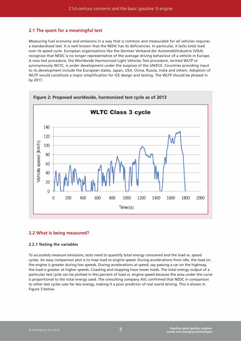
2.1 The quest for a meaningful test
Measuring fuel economy and emissions in a way that is common and measurable for all vehicles requires
a standardized test. It is well known that the NEDC has its deficiencies. In particular, it lacks total load
over its speed cycle. European organizations like the German Verband der Automobilindustrie (VDA)
recognize that NEDC is no longer representative of the average driving behaviour of a vehicle in Europe.
A new test procedure, the Worldwide Harmonized Light Vehicles Test procedure, termed WLTP or
synonymously WLTC, is under development under the auspices of the UN/ECE. Countries providing input
to its development include the European states, Japan, USA, China, Russia, India and others. Adoption of
WLTP would constitute a major simplification for ICE design and testing. The WLTP should be phased in
by 2017.
Figure 2: Proposed worldwide, harmonized test cycle as of 2013
2.2 What is being measured?
2.2.1 Testing the variables
To accurately measure emissions, tests need to quantify total energy consumed and the load vs. speed
cycles. An easy comparison plot is to map load to engine speed. During accelerations from idle, the load on
the engine is greater during low speeds. During accelerations at speed, say passing a car on the highway,
the load is greater at higher speeds. Coasting and stopping have lower loads. The total energy output of a
particular test cycle can be plotted in this percent of load vs. engine speed because the area under the curve
is proportional to the total energy used. The consulting company AVL confirmed that NEDC in comparison
to other test cycles uses far less energy, making it a poor predictor of real world driving. This is shown in
Figure 3 below.
WLTC Class 3 cycle
� � � � � � �� � �� � ������ ���

19© Autelligence ApS 2015Gasoline spark ignition engines:
trends and emerging technologies
Gasoline SI engines basics
One of the major techniques for improving fuel efficiency is increasing the compression ratio, the volume of
the combustion chamber from its largest capacity to its smallest capacity. Higher compression ratios permit
the same combustion temperature to be reached with less fuel, while giving a longer expansion cycle. This
creates more mechanical power output and lowers the exhaust temperature for better efficiency.
Other techniques for improving fuel economy that are growing in popularity recently are direct injection,
boosting (especially when combined with direct injection), and so-called lean burn. Boosting through
turbocharging scavenges waste energy in the exhaust stream. All are limited by knock.
Knock is uncontrolled ignition during combustion. Instead of a smooth flame front moving through the
combustion chamber, hot spots will auto-ignite unpredictably in the remaining air-fuel mixture ahead of
the flame front, called the end-gas. Excessive temperature and pressures in localized spots result. Beyond
annoying drivers, excessive knock can wear engines faster and even catastrophically damage pistons and
cylinders. Geometry of the piston, injection strategies, spark timing, and octane levels of fuels are just some
of the design factors that affect knock. As Dr. Terry Alger of the Southwest Research Institute (SwRI) stated
in February, 2012 “knock and the resulting engineering compromises to avoid it reduce the benefit from
every … source of efficiency improvement technology.”
Figure 15: Knock is ignition ahead of the smooth flame front
� � � � � � � � � � � � � � � � ! " � # � � � � � $ % � � & ' � & � & � � ( � � ) * !+ , � - � + � � � �. / 0 1 2 / 3 4 56 � � � � - � � � � � � � � � � 6 � � !7 8 9 : ; <= ; : 8 ; <
Note: Excessive knock can damage pistons and reduce life of components. High compression ratios, low-octane fuel, and other factors contribute to knock.
3.2 Analysing engine efficiency
The basic engine/drive architecture of practically all light duty vehicles today is to connect the crankshaft
to the driving wheels through a mechanical drive train and geared transmission. This means that the driver
through an accelerator pedal feeds more or less gasoline and air into the engine to make it go faster or
slower through a throttle plate. The efficiency of the engine depends on the speed and load the engine
is operating at. The best efficiency is near where the engine is producing maximum torque, usually at
a particular engine speed that is just right, not too fast and not too slow. At low speeds and low loads,
engine friction dominates and creates huge inefficiencies. At higher speeds and low loads, this is even more

29© Autelligence ApS 2015Gasoline spark ignition engines:
trends and emerging technologies
Standards and regulatory mechanisms governing types of emissions and fuel economy
Figure 23: Relatively stable gasoline prices, inflation adjusted, are forecast
>?@AB
? > > C ? > D E ? > ? > ? > ? C ? > E > ? > E C ? > @ >
? > D E F G H I J K L M H N OP M O L H G QR J S J G J N K JP M T U V M W F G M K J
X H Y V M W F G M K JZ[\]̂ _`̀ abcdebfa`̀ _g
Source: 2015 Annual Energy Outlook USA EIA
A plausible assumption underpinning this report is that gasoline will continue to be available at a price
within reach of most new car buyers, much more so than in 2013. This leads to a concern about the current
focus on fuel efficiency as a customer desire. Will it continue? Will future car buyers, worldwide, remain as
concerned about fuel economy?
4.5 Analysing the chemistry of fuel in relation to fuel economy
The octane level of gasoline affects the knock-limit of an engine. The lower the octane rating, the more
tendency of the fuel to knock. That is why many high performance cars, with high compression ratios,
require the use of high-octane premium fuels for best performance. Most engines today have a knock
sensor that adjusts timing of the engine if lower octane fuel is used and the engine begins to knock
excessively. A key point is that if an engine is designed with a higher compression ratio, it can get better
fuel economy. High compression ratios are often limited by having to design for lower octane fuel.
Octane is measured using two tests. They are comparative tests, measuring how the measured fuel
compares to a primary reference fuel (PRF) composed of only two organic compounds, iso-octane and
n-heptane. Real fuels are composed of hundreds if not thousands of individual constituents, from toluene
to benzene, as well as smaller fractions of iso-octane and n-heptane. If the measured fuel behaves like a
mix of 95% iso-octane and 5% n-heptane, it will be assigned a 95 octane number.
The Research Octane Number (RON) method is run in a single cylinder research engine at 600 RPM
with intake air at 52 degrees C; the Motor Octane Number (MON) is run at 900 RPM with intake air at
149 degrees C. The MON tends to measure a lesser octane number than RON for any fuel. The difference
(RON – MON) is the fuel sensitivity. In Europe, octane on the pump is RON, in North America it is the
Antiknock Index, calculated from (RON + MON)/2.
Another important point is that ethanol blends – up to about 30% – will increase the octane level of the
gasoline it is mixed with. This is according to a study conducted by the American Petroleum Institute in
April, 2010. So, as the volume of ethanol blend rises above 15%, the API study shows that gasoline can
improve 6 to 8 points on the Antiknock Index for regular unleaded gasoline. Premium gasoline’s Antiknock
Index improved less, mainly because it is so high to begin with. Up to a point, this can improve fuel
economy for cars designed with higher compression ratios, even taking into account the lower energy
contained in the ethanol.
37© Autelligence ApS 2015Gasoline spark ignition engines:
trends and emerging technologies
Improving engine efficiency and performance
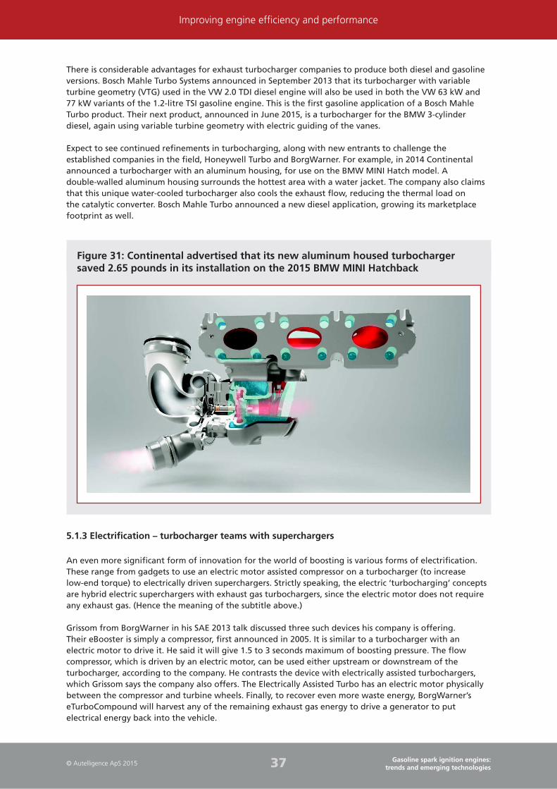
There is considerable advantages for exhaust turbocharger companies to produce both diesel and gasoline
versions. Bosch Mahle Turbo Systems announced in September 2013 that its turbocharger with variable
turbine geometry (VTG) used in the VW 2.0 TDI diesel engine will also be used in both the VW 63 kW and
77 kW variants of the 1.2-litre TSI gasoline engine. This is the first gasoline application of a Bosch Mahle
Turbo product. Their next product, announced in June 2015, is a turbocharger for the BMW 3-cylinder
diesel, again using variable turbine geometry with electric guiding of the vanes.
Expect to see continued refinements in turbocharging, along with new entrants to challenge the
established companies in the field, Honeywell Turbo and BorgWarner. For example, in 2014 Continental
announced a turbocharger with an aluminum housing, for use on the BMW MINI Hatch model. A
double-walled aluminum housing surrounds the hottest area with a water jacket. The company also claims
that this unique water-cooled turbocharger also cools the exhaust flow, reducing the thermal load on
the catalytic converter. Bosch Mahle Turbo announced a new diesel application, growing its marketplace
footprint as well.
Figure 31: Continental advertised that its new aluminum housed turbocharger saved 2.65 pounds in its installation on the 2015 BMW MINI Hatchback
5.1.3 Electrification – turbocharger teams with superchargers
An even more significant form of innovation for the world of boosting is various forms of electrification.
These range from gadgets to use an electric motor assisted compressor on a turbocharger (to increase
low-end torque) to electrically driven superchargers. Strictly speaking, the electric ‘turbocharging’ concepts
are hybrid electric superchargers with exhaust gas turbochargers, since the electric motor does not require
any exhaust gas. (Hence the meaning of the subtitle above.)
Grissom from BorgWarner in his SAE 2013 talk discussed three such devices his company is offering.
Their eBooster is simply a compressor, first announced in 2005. It is similar to a turbocharger with an
electric motor to drive it. He said it will give 1.5 to 3 seconds maximum of boosting pressure. The flow
compressor, which is driven by an electric motor, can be used either upstream or downstream of the
turbocharger, according to the company. He contrasts the device with electrically assisted turbochargers,
which Grissom says the company also offers. The Electrically Assisted Turbo has an electric motor physically
between the compressor and turbine wheels. Finally, to recover even more waste energy, BorgWarner’s
eTurboCompound will harvest any of the remaining exhaust gas energy to drive a generator to put
electrical energy back into the vehicle.

54© Autelligence ApS 2015Gasoline spark ignition engines:
trends and emerging technologies
Engine technology advances
Figure 46: The ideal cycle for engine operation is shown in this diagram, with a V8 using only half its cylinders in cruise mode
Source: © Audi
Audi will debut the deactivation system in three of its gasoline engines: the 1.4 TFSI COD I-4, the 4.0 TFSI
COD V-6, and the W12 COD 12-cylinder.
Notably, not all automakers have embraced cylinder deactivation. For example, Ford investigated the idea
in the early 2000s, but have yet to offer it commercially.
Claims for fuel economy improvement range from 6–8%, based on EPA tests, up to 20% by Audi in a 2013
press release.
6.9 Variable compression ratio engines
Recall from Chapter 3 Gasoline SI engine basics, that a small portion of the engine torque/speed map
sets the compression ratio of the engine. The limit tends to be in the low-speed, high load area. When
the engine is operating in other conditions of load and speed, theoretically a higher compression ratio is
acceptable and thermal efficiency would be greater. The motivation behind creating a variable compression
ratio engine that would vary with speed, load, or both with the engine running is to create higher
compression ratios at different load/speed points.
VCR schemes often vary the length of the connecting rod, allowing more or less travel in the piston to
achieve more or less compression ratio. Saab in 2000 developed a VCR engine that actually moved the
cylinder head up or down by pivoting on a hinge. According to many sources, VCR is not likely to be
introduced before 2020, possibly not before 2025. Table 4 below lists some of the more viable approaches
to VCR for SI gasoline engines.
69© Autelligence ApS 2015Gasoline spark ignition engines:
trends and emerging technologies
Major OEM engine strategies
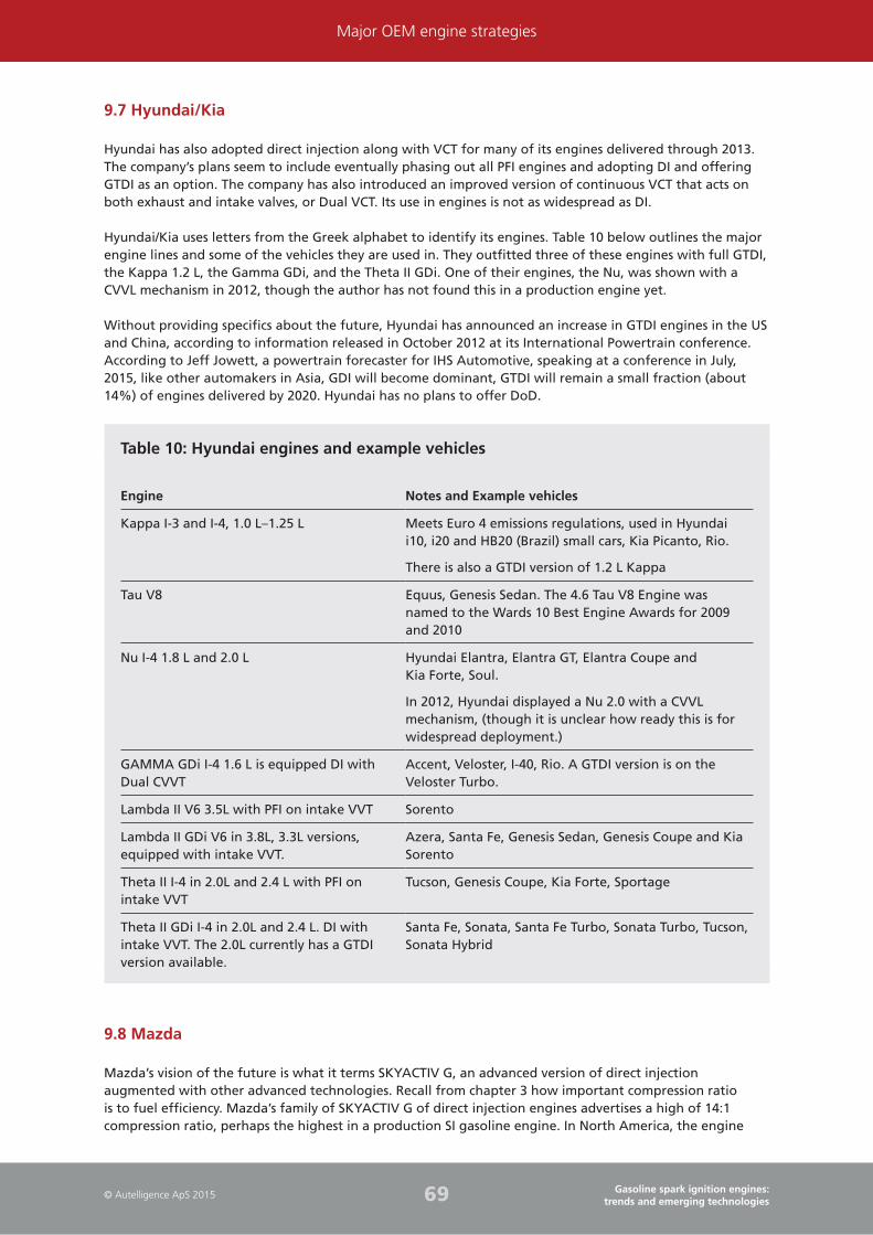
9.7 Hyundai/Kia
Hyundai has also adopted direct injection along with VCT for many of its engines delivered through 2013.
The company’s plans seem to include eventually phasing out all PFI engines and adopting DI and offering
GTDI as an option. The company has also introduced an improved version of continuous VCT that acts on
both exhaust and intake valves, or Dual VCT. Its use in engines is not as widespread as DI.
Hyundai/Kia uses letters from the Greek alphabet to identify its engines. Table 10 below outlines the major
engine lines and some of the vehicles they are used in. They outfitted three of these engines with full GTDI,
the Kappa 1.2 L, the Gamma GDi, and the Theta II GDi. One of their engines, the Nu, was shown with a
CVVL mechanism in 2012, though the author has not found this in a production engine yet.
Without providing specifics about the future, Hyundai has announced an increase in GTDI engines in the US
and China, according to information released in October 2012 at its International Powertrain conference.
According to Jeff Jowett, a powertrain forecaster for IHS Automotive, speaking at a conference in July,
2015, like other automakers in Asia, GDI will become dominant, GTDI will remain a small fraction (about
14%) of engines delivered by 2020. Hyundai has no plans to offer DoD.
Table 10: Hyundai engines and example vehicles
Engine Notes and Example vehicles
Kappa I-3 and I-4, 1.0 L–1.25 L Meets Euro 4 emissions regulations, used in Hyundai
i10, i20 and HB20 (Brazil) small cars, Kia Picanto, Rio.
There is also a GTDI version of 1.2 L Kappa
Tau V8 Equus, Genesis Sedan. The 4.6 Tau V8 Engine was
named to the Wards 10 Best Engine Awards for 2009
and 2010
Nu I-4 1.8 L and 2.0 L Hyundai Elantra, Elantra GT, Elantra Coupe and
Kia Forte, Soul.
In 2012, Hyundai displayed a Nu 2.0 with a CVVL
mechanism, (though it is unclear how ready this is for
widespread deployment.)
GAMMA GDi I-4 1.6 L is equipped DI with
Dual CVVT
Accent, Veloster, I-40, Rio. A GTDI version is on the
Veloster Turbo.
Lambda II V6 3.5L with PFI on intake VVT Sorento
Lambda II GDi V6 in 3.8L, 3.3L versions,
equipped with intake VVT.
Azera, Santa Fe, Genesis Sedan, Genesis Coupe and Kia
Sorento
Theta II I-4 in 2.0L and 2.4 L with PFI on
intake VVT
Tucson, Genesis Coupe, Kia Forte, Sportage
Theta II GDi I-4 in 2.0L and 2.4 L. DI with
intake VVT. The 2.0L currently has a GTDI
version available.
Santa Fe, Sonata, Santa Fe Turbo, Sonata Turbo, Tucson,
Sonata Hybrid
9.8 Mazda
Mazda’s vision of the future is what it terms SKYACTIV G, an advanced version of direct injection
augmented with other advanced technologies. Recall from chapter 3 how important compression ratio
is to fuel efficiency. Mazda’s family of SKYACTIV G of direct injection engines advertises a high of 14:1
compression ratio, perhaps the highest in a production SI gasoline engine. In North America, the engine
80© Autelligence ApS 2015Gasoline spark ignition engines:
trends and emerging technologies
Gasoline SI engine component suppliers profiles
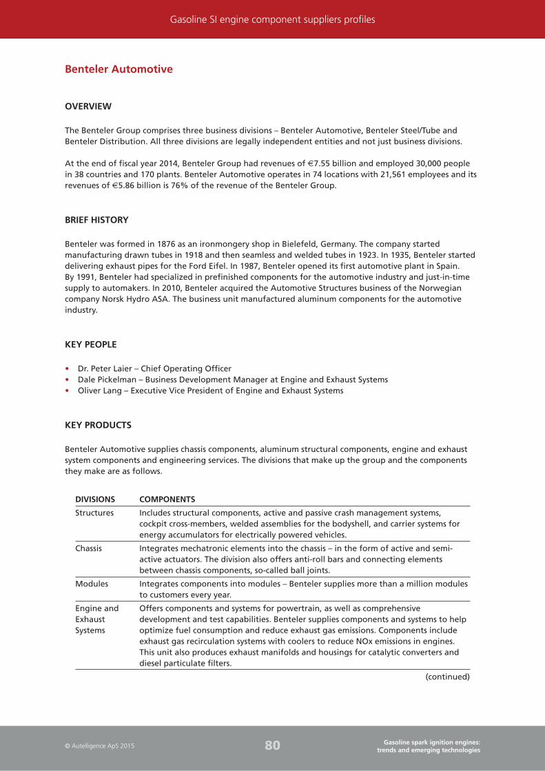
Benteler Automotive
OVERVIEW
The Benteler Group comprises three business divisions – Benteler Automotive, Benteler Steel/Tube and
Benteler Distribution. All three divisions are legally independent entities and not just business divisions.
At the end of fiscal year 2014, Benteler Group had revenues of €7.55 billion and employed 30,000 people
in 38 countries and 170 plants. Benteler Automotive operates in 74 locations with 21,561 employees and its
revenues of €5.86 billion is 76% of the revenue of the Benteler Group.
BRIEF HISTORY
Benteler was formed in 1876 as an ironmongery shop in Bielefeld, Germany. The company started
manufacturing drawn tubes in 1918 and then seamless and welded tubes in 1923. In 1935, Benteler started
delivering exhaust pipes for the Ford Eifel. In 1987, Benteler opened its first automotive plant in Spain.
By 1991, Benteler had specialized in prefinished components for the automotive industry and just-in-time
supply to automakers. In 2010, Benteler acquired the Automotive Structures business of the Norwegian
company Norsk Hydro ASA. The business unit manufactured aluminum components for the automotive
industry.
KEY PEOPLE
• Dr. Peter Laier – Chief Operating Officer
• Dale Pickelman – Business Development Manager at Engine and Exhaust Systems
• Oliver Lang – Executive Vice President of Engine and Exhaust Systems
KEY PRODUCTS
Benteler Automotive supplies chassis components, aluminum structural components, engine and exhaust
system components and engineering services. The divisions that make up the group and the components
they make are as follows.
DIVISIONS COMPONENTS
Structures Includes structural components, active and passive crash management systems,
cockpit cross-members, welded assemblies for the bodyshell, and carrier systems for
energy accumulators for electrically powered vehicles.
Chassis Integrates mechatronic elements into the chassis – in the form of active and semi-
active actuators. The division also offers anti-roll bars and connecting elements
between chassis components, so-called ball joints.
Modules Integrates components into modules – Benteler supplies more than a million modules
to customers every year.
Engine and
Exhaust
Systems
Offers components and systems for powertrain, as well as comprehensive
development and test capabilities. Benteler supplies components and systems to help
optimize fuel consumption and reduce exhaust gas emissions. Components include
exhaust gas recirculation systems with coolers to reduce NOx emissions in engines.
This unit also produces exhaust manifolds and housings for catalytic converters and
diesel particulate filters.
(continued)

99© Autelligence ApS 2015Gasoline spark ignition engines:
trends and emerging technologies
Gasoline SI engine component suppliers profiles
CLIENT FOCUS
PRODUCT/SERVICE DATE
Automotive partners in the US
Ford Supercharger for 2013 Ford Mustang 2013
Automotive partners outside US
Audi Supplied supercharger Dec 2010
Nissan Supercharger for 1.2L Three-cylinder engine Nov 2012
Volkswagen Superturbo for 1.4L gasoline engine Oct 2005
Gasoline Engines
In the area of gasoline engines, Eaton supplies Superchargers, Oil coolers, Oil Control Valves, Engine Valves,
Lifters and Valve actuation systems.
REVENUE ANALYSIS
MARKET ESTIMATED GLOBAL VALUE
(CAGR 2015–2020)
REVENUE OF EATON’S VEHICLE
DIVISION IN 2014
% CHANGE FROM
THE PREVIOUS YEAR
Vehicle Division US$4 billion 4.4% increase
As of 31 December 2014, revenue of Eaton amounted to US$22.6 billion representing an increase of 2.29%
from the previous year 2013 which amounted to US$22 billion due to an increase in organic sales of 4%,
partially offset by a decrease of 1% from the impact of currency translation and a decrease of 1% from
the divestiture of Eaton’s Aerospace Power Distribution Management Solutions and Integrated Cockpit
Solutions businesses. The increase in organic sales in 2014 is primarily due to growth in the company’s end
markets, particularly in North America.
The Automotive business accounted for 18% of the company’s total sales in the fiscal year 2014 which
amounted to US$4006 million representing an increase of 4.45% from the previous year 2013 which
amounted to US$3835 million due to an increase in organic sales of 6%, partially offset by a decrease of
2% from the impact of currency translation. The increase in organic sales in 2014 was primarily due to
strong demand in North American and selected Asian Pacific markets, partially offset by weakness in South
American markets.
Research & Development
As of 31 December 2014 R&D of Eaton amounted to US$647 million representing an increase of 1% from
the previous year 2013 which amounted to US$644 million. R&D expenditure nearly accounts for 3% of the
total sales. Eaton has Engineering, Research and Development centres in Marshall, Michigan; Turin, Italy;
Baden, Germany; Pune, India; and Shanghai, China. The company has a strong emphasis on R&D and holds
nearly 11,000 patents (more than 2000 of which come from Cooper).
113© Autelligence ApS 2015Gasoline spark ignition engines:
trends and emerging technologies
Gasoline SI engine component suppliers profiles
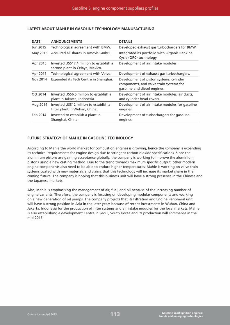
LATEST ABOUT MAHLE IN GASOLINE TECHNOLOGY MANUFACTURING
DATE ANNOUNCEMENTS DETAILS
Jun 2015 Technological agreement with BMW. Developed exhaust gas turbochargers for BMW.
May 2015 Acquired all shares in Amovis GmbH. Integrated its portfolio with Organic Rankine
Cycle (ORC) technology.
Apr 2015 Invested US$17.4 million to establish a
second plant in Celaya, Mexico.
Development of air intake modules.
Apr 2015 Technological agreement with Volvo. Development of exhaust gas turbochargers.
Nov 2014 Expanded its Tech Centre in Shanghai. Development of piston systems, cylinder
components, and valve train systems for
gasoline and diesel engines.
Oct 2014 Invested US$6.5 million to establish a
plant in Jakarta, Indonesia.
Development of air intake modules, air ducts,
and cylinder head covers.
Aug 2014 Invested US$12 million to establish a
filter plant in Wuhan, China.
Development of air intake modules for gasoline
engines.
Feb 2014 Invested to establish a plant in
Shanghai, China.
Development of turbochargers for gasoline
engines.
FUTURE STRATEGY OF MAHLE IN GASOLINE TECHNOLOGY
According to Mahle the world market for combustion engines is growing, hence the company is expanding
its technical requirements for engine design due to stringent carbon-dioxide specifications. Since the
aluminium pistons are gaining acceptance globally, the company is working to improve the aluminium
pistons using a new casting method. Due to the trend towards maximum specific output, other modern
engine components also need to be able to endure higher temperatures; Mahle is working on valve train
systems coated with new materials and claims that this technology will increase its market share in the
coming future. The company is hoping that this business unit will have a strong presence in the Chinese and
the Japanese markets.
Also, Mahle is emphasising the management of air, fuel, and oil because of the increasing number of
engine variants. Therefore, the company is focusing on developing modular components and working
on a new generation of oil pumps. The company projects that its Filtration and Engine Peripheral unit
will have a strong position in Asia in the later years because of recent investments in Wuhan, China and
Jakarta, Indonesia for the production of filter systems and air intake modules for the local markets. Mahle
is also establishing a development Centre in Seoul, South Korea and its production will commence in the
mid-2015.

Autelligence ApS
Vesterbakken 25
Høruphav
6470 Sydals
Denmark
tel: +45 2334 0705
e-mail: [email protected]
web: www.autelligence.com