gas plant training module 4 - amazon web services plant training module iv: teg dehydration systems...
TRANSCRIPT
Gas Plant Training
Module 4
TEG Dehydration Systems
Gas Plant Training
Module IV: TEG Dehydration Systems
Effective Date: 05/07/2012 Module #4: Dehydration Systems
4-1
Table of Contents
Introduction ...................................................................................................................................................2
Objectives .......................................................................................................................................................2
Glycol Dehydration .......................................................................................................................................3
Dehydration System Process Control ..........................................................................................................4
Contactor C301 ...........................................................................................................................................6
Glycol Regenerator .....................................................................................................................................7
Flash Separator V308..................................................................................................................................8
Lean/Rich Exchanger E309 ........................................................................................................................9
Gas/Glycol Exchanger E302 .......................................................................................................................9
Glycol Filters F306/307 ............................................................................................................................ 10
Glycol Pumps P305A/B ............................................................................................................................ 11
Still O/H Condenser AR311 ..................................................................................................................... 12
Module References ...................................................................................................................................... 12
Module 4 Exercises ...................................................................................................................................... 13
Written Exercises ~ Self-Assessed ........................................................................................................... 13
Answer Key .......................................................................................................................................... 15
Gas Plant Training
Module IV: TEG Dehydration Systems
Effective Date: 05/07/2012 Module #4: Dehydration Systems
4-2
Introduction
In this module, you will learn about TEG (triethylene glycol) gas dehydration systems.
You will understand the principles behind natural gas dehydration using glycol as well as
the process for regenerating the water-saturated glycol.
Objectives
After completing the Dehydration Systems module, you will be able to:
Describe process flows for:
Gas stream
Rich glycol stream
Lean glycol stream
Fuel gas
State normal operating parameters for:
Contactor
Regenerator
Flash Separator
Glycol pumps
Explain why glycol temperature control is critical, and why temperature differs for
the Contactor and Regenerator processes
Gas Plant Training
Module IV: TEG Dehydration Systems
Effective Date: 05/07/2012 Module #4: Dehydration Systems
4-3
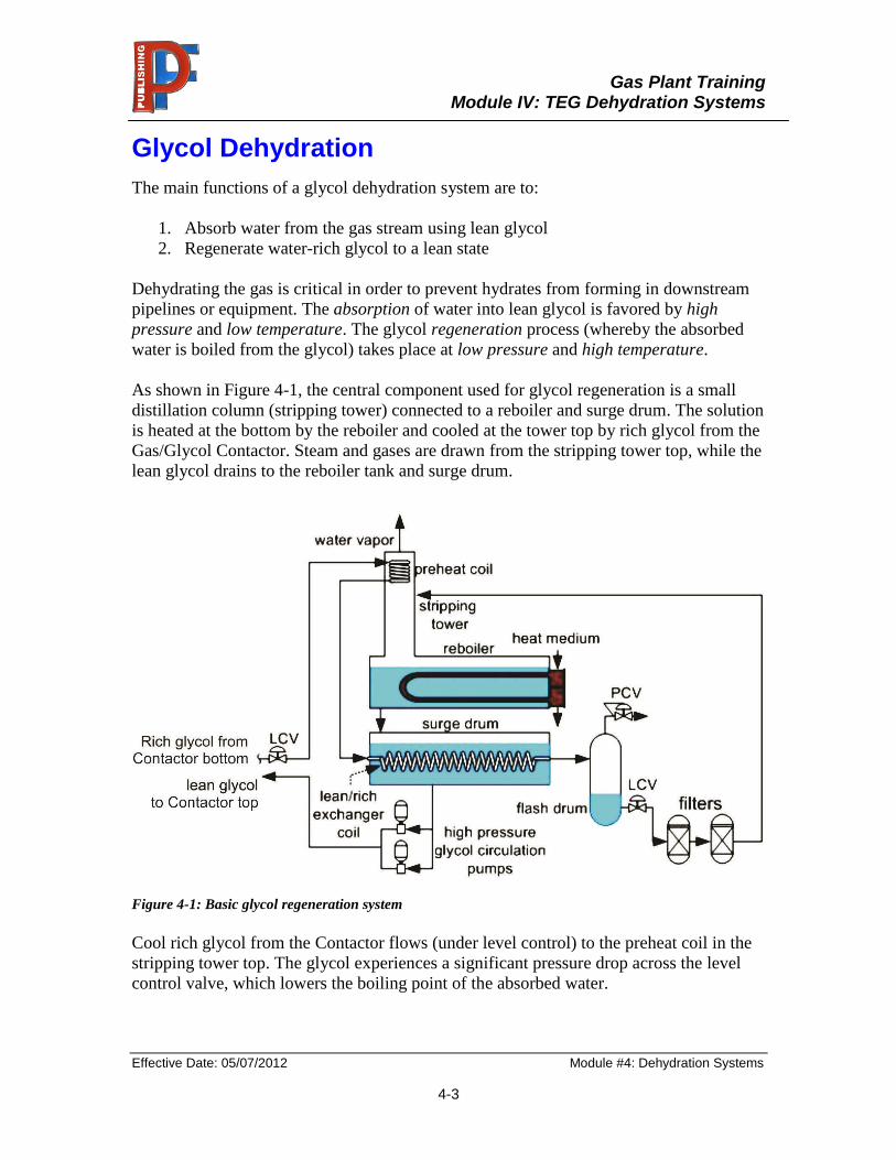
Glycol Dehydration
The main functions of a glycol dehydration system are to:
1. Absorb water from the gas stream using lean glycol
2. Regenerate water-rich glycol to a lean state
Dehydrating the gas is critical in order to prevent hydrates from forming in downstream
pipelines or equipment. The absorption of water into lean glycol is favored by high
pressure and low temperature. The glycol regeneration process (whereby the absorbed
water is boiled from the glycol) takes place at low pressure and high temperature.
As shown in Figure 4-1, the central component used for glycol regeneration is a small
distillation column (stripping tower) connected to a reboiler and surge drum. The solution
is heated at the bottom by the reboiler and cooled at the tower top by rich glycol from the
Gas/Glycol Contactor. Steam and gases are drawn from the stripping tower top, while the
lean glycol drains to the reboiler tank and surge drum.
Figure 4-1: Basic glycol regeneration system
Cool rich glycol from the Contactor flows (under level control) to the preheat coil in the
stripping tower top. The glycol experiences a significant pressure drop across the level
control valve, which lowers the boiling point of the absorbed water.

Gas Plant Training
Module IV: TEG Dehydration Systems
Effective Date: 05/07/2012 Module #4: Dehydration Systems
4-4
The pre-heat coil has two purposes:
1. The rich glycol picks up some “free heat” on its way to being regenerated, and
2. The rich glycol cools vapors rising through the stripping tower, thereby
condensing any residual glycol vapors entrained with the O/H water vapor.
From the pre-heat coil, the rich glycol flows through the lean/rich exchanger, which in
the example above is a coil submerged in the lean glycol accumulator – other systems use
external plate-type heat exchangers (or a combination of both types). The lean/rich
exchanger uses inflowing rich glycol to cool the outflowing lean glycol (recall that water
absorption works best at low temperatures). At the same time, the rich glycol picks up
more “free” heat on its way to regeneration. (Use of a lean/rich exchanger reduces
reboiler heat requirements by ~50%.)
From the lean/rich exchanger, the rich glycol enters the glycol flash drum (also termed a
“flash tank” or “flash separator”), where any dissolved hydrocarbon gases boil off due to
the combined effects of:
1. The pressure drop across the LCV
2. The temperature increase from preheating
Flash Drum O/H gas is recycled (or flared), while the rich glycol flows through filters to
the distillation column (stripping tower), where it mixes with hot, rising vapors generated
in the reboiler. Reboiler heat vaporizes water in the rich glycol returning it to a lean state.
Following regeneration, the lean glycol is approximately 70% glycol and 30% water.
Dehydration System Process Control
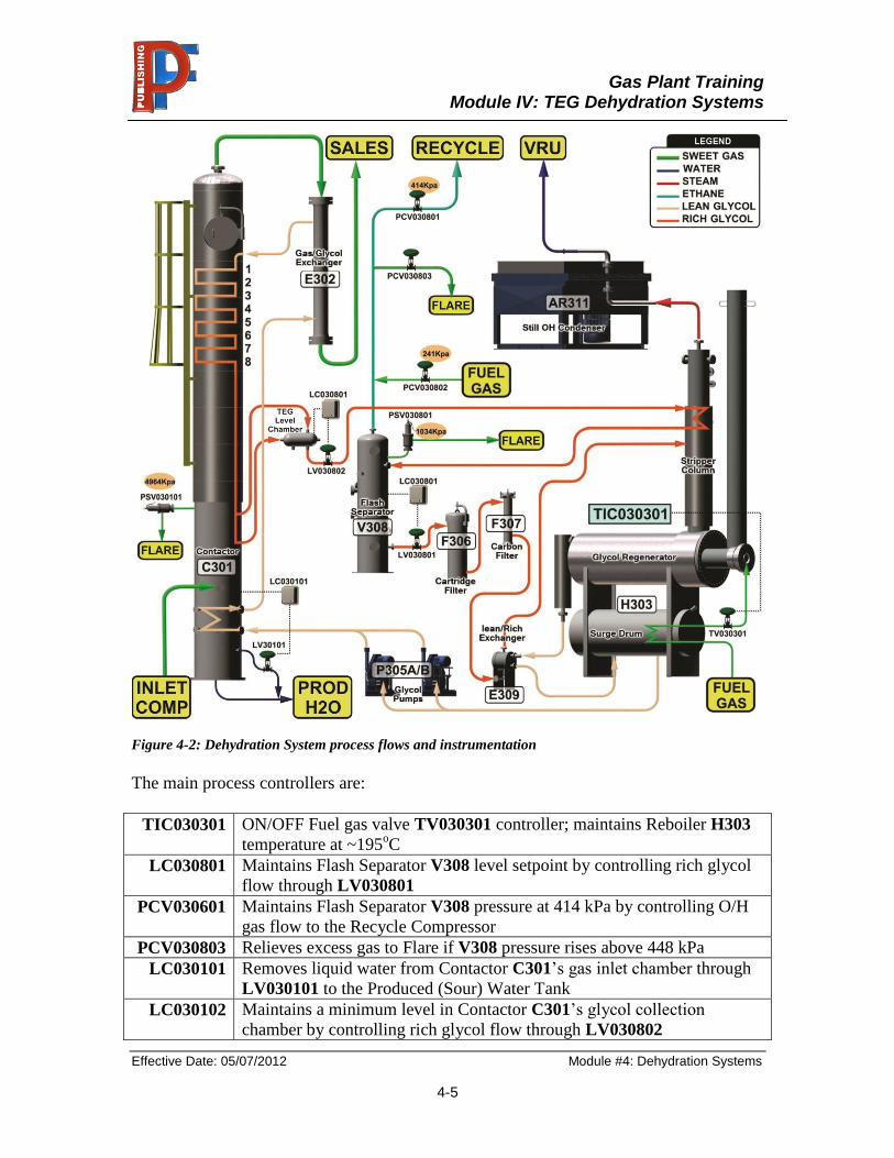
The Dehydration System shown in Figure 4-2 is comprised of:
Contactor C301
Gas/Glycol Exchanger E302
TEG Level Chamber
Flash Separator V308
Particulate Filter F306
Carbon Filter F307
Lean/Rich Glycol Exchanger E309
Glycol Regenerator H303
Glycol Pumps P305A/B
Gas Plant Training
Module IV: TEG Dehydration Systems
Effective Date: 05/07/2012 Module #4: Dehydration Systems
4-5
Figure 4-2: Dehydration System process flows and instrumentation
The main process controllers are:
TIC030301 ON/OFF Fuel gas valve TV030301 controller; maintains Reboiler H303
temperature at ~195oC
LC030801 Maintains Flash Separator V308 level setpoint by controlling rich glycol
flow through LV030801
PCV030601 Maintains Flash Separator V308 pressure at 414 kPa by controlling O/H
gas flow to the Recycle Compressor
PCV030803 Relieves excess gas to Flare if V308 pressure rises above 448 kPa
LC030101 Removes liquid water from Contactor C301’s gas inlet chamber through
LV030101 to the Produced (Sour) Water Tank
LC030102 Maintains a minimum level in Contactor C301’s glycol collection
chamber by controlling rich glycol flow through LV030802
Gas Plant Training
Module IV: TEG Dehydration Systems
Effective Date: 05/07/2012 Module #4: Dehydration Systems
4-6
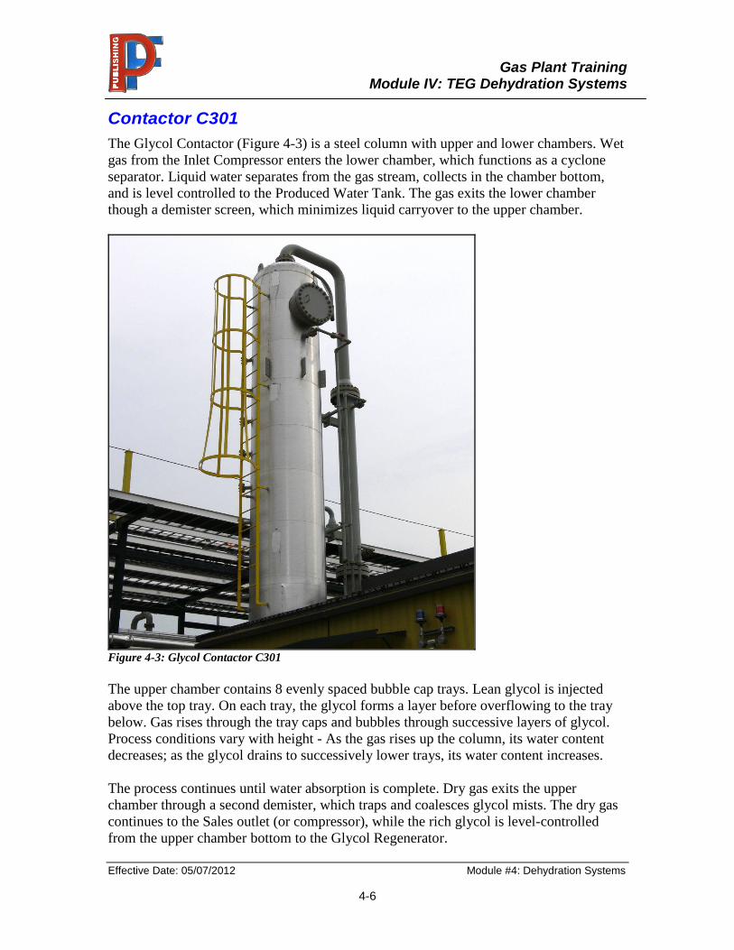
Contactor C301
The Glycol Contactor (Figure 4-3) is a steel column with upper and lower chambers. Wet
gas from the Inlet Compressor enters the lower chamber, which functions as a cyclone
separator. Liquid water separates from the gas stream, collects in the chamber bottom,
and is level controlled to the Produced Water Tank. The gas exits the lower chamber
though a demister screen, which minimizes liquid carryover to the upper chamber.
Figure 4-3: Glycol Contactor C301
The upper chamber contains 8 evenly spaced bubble cap trays. Lean glycol is injected
above the top tray. On each tray, the glycol forms a layer before overflowing to the tray
below. Gas rises through the tray caps and bubbles through successive layers of glycol.
Process conditions vary with height - As the gas rises up the column, its water content
decreases; as the glycol drains to successively lower trays, its water content increases.
The process continues until water absorption is complete. Dry gas exits the upper
chamber through a second demister, which traps and coalesces glycol mists. The dry gas
continues to the Sales outlet (or compressor), while the rich glycol is level-controlled
from the upper chamber bottom to the Glycol Regenerator.
Gas Plant Training
Module IV: TEG Dehydration Systems
Effective Date: 05/07/2012 Module #4: Dehydration Systems
4-7
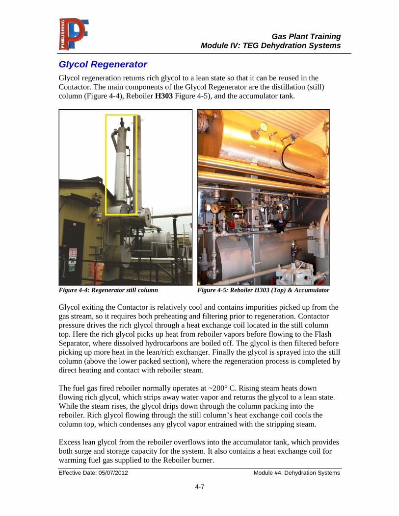
Glycol Regenerator
Glycol regeneration returns rich glycol to a lean state so that it can be reused in the
Contactor. The main components of the Glycol Regenerator are the distillation (still)
column (Figure 4-4), Reboiler H303 Figure 4-5), and the accumulator tank.
Figure 4-4: Regenerator still column Figure 4-5: Reboiler H303 (Top) & Accumulator
Glycol exiting the Contactor is relatively cool and contains impurities picked up from the
gas stream, so it requires both preheating and filtering prior to regeneration. Contactor
pressure drives the rich glycol through a heat exchange coil located in the still column
top. Here the rich glycol picks up heat from reboiler vapors before flowing to the Flash
Separator, where dissolved hydrocarbons are boiled off. The glycol is then filtered before
picking up more heat in the lean/rich exchanger. Finally the glycol is sprayed into the still
column (above the lower packed section), where the regeneration process is completed by
direct heating and contact with reboiler steam.
The fuel gas fired reboiler normally operates at ~200° C. Rising steam heats down
flowing rich glycol, which strips away water vapor and returns the glycol to a lean state.
While the steam rises, the glycol drips down through the column packing into the
reboiler. Rich glycol flowing through the still column’s heat exchange coil cools the
column top, which condenses any glycol vapor entrained with the stripping steam.
Excess lean glycol from the reboiler overflows into the accumulator tank, which provides
both surge and storage capacity for the system. It also contains a heat exchange coil for
warming fuel gas supplied to the Reboiler burner.
Gas Plant Training
Module IV: TEG Dehydration Systems
Effective Date: 05/07/2012 Module #4: Dehydration Systems
4-8
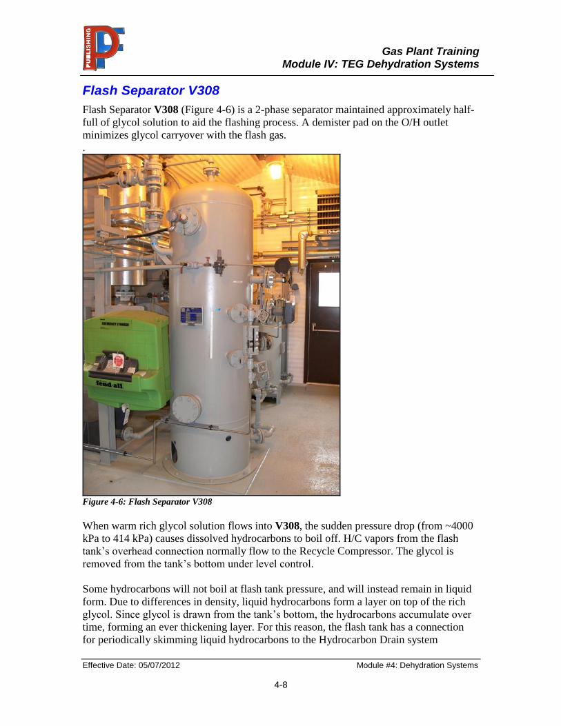
Flash Separator V308
Flash Separator V308 (Figure 4-6) is a 2-phase separator maintained approximately half-
full of glycol solution to aid the flashing process. A demister pad on the O/H outlet
minimizes glycol carryover with the flash gas.
.
Figure 4-6: Flash Separator V308
When warm rich glycol solution flows into V308, the sudden pressure drop (from ~4000
kPa to 414 kPa) causes dissolved hydrocarbons to boil off. H/C vapors from the flash
tank’s overhead connection normally flow to the Recycle Compressor. The glycol is
removed from the tank’s bottom under level control.
Some hydrocarbons will not boil at flash tank pressure, and will instead remain in liquid
form. Due to differences in density, liquid hydrocarbons form a layer on top of the rich
glycol. Since glycol is drawn from the tank’s bottom, the hydrocarbons accumulate over
time, forming an ever thickening layer. For this reason, the flash tank has a connection
for periodically skimming liquid hydrocarbons to the Hydrocarbon Drain system
Gas Plant Training
Module IV: TEG Dehydration Systems
Effective Date: 05/07/2012 Module #4: Dehydration Systems
4-9
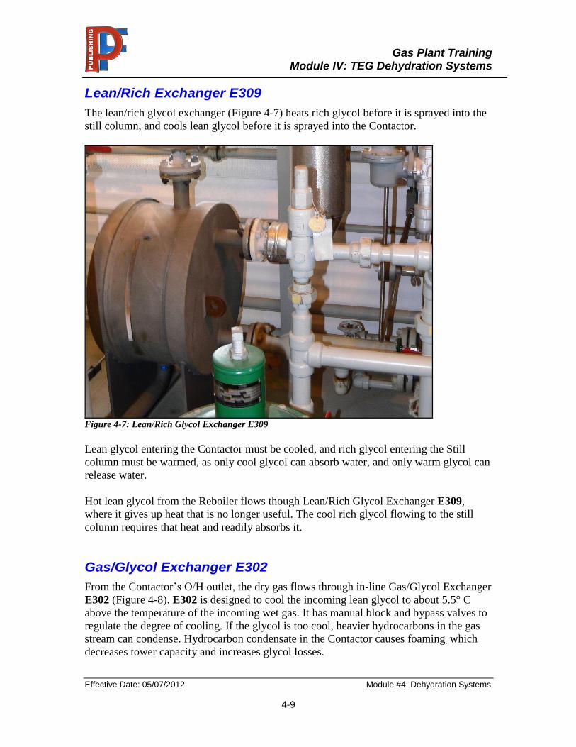
Lean/Rich Exchanger E309
The lean/rich glycol exchanger (Figure 4-7) heats rich glycol before it is sprayed into the
still column, and cools lean glycol before it is sprayed into the Contactor.
Figure 4-7: Lean/Rich Glycol Exchanger E309
Lean glycol entering the Contactor must be cooled, and rich glycol entering the Still
column must be warmed, as only cool glycol can absorb water, and only warm glycol can
release water.
Hot lean glycol from the Reboiler flows though Lean/Rich Glycol Exchanger E309,
where it gives up heat that is no longer useful. The cool rich glycol flowing to the still
column requires that heat and readily absorbs it.
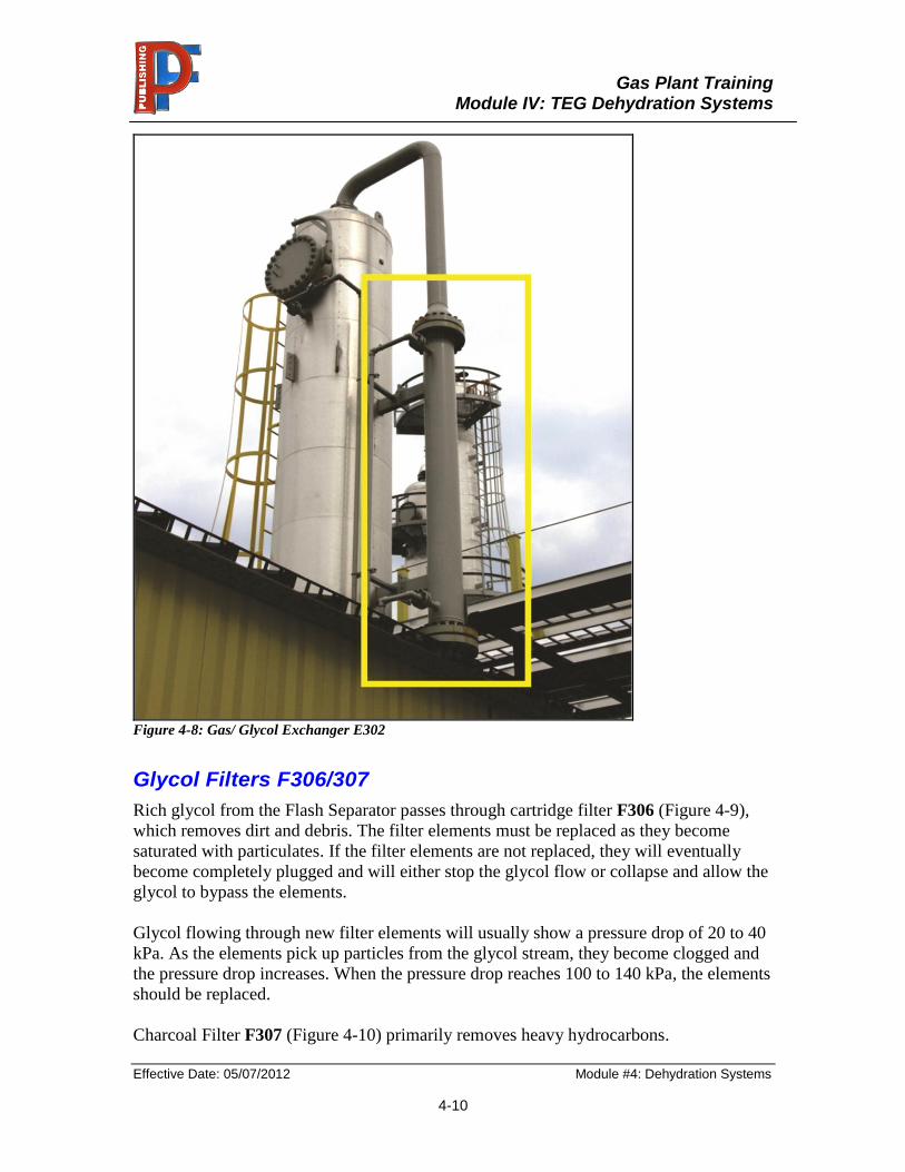
Gas/Glycol Exchanger E302
From the Contactor’s O/H outlet, the dry gas flows through in-line Gas/Glycol Exchanger
E302 (Figure 4-8). E302 is designed to cool the incoming lean glycol to about 5.5° C
above the temperature of the incoming wet gas. It has manual block and bypass valves to
regulate the degree of cooling. If the glycol is too cool, heavier hydrocarbons in the gas
stream can condense. Hydrocarbon condensate in the Contactor causes foaming, which
decreases tower capacity and increases glycol losses.
Gas Plant Training
Module IV: TEG Dehydration Systems
Effective Date: 05/07/2012 Module #4: Dehydration Systems
4-10
Figure 4-8: Gas/ Glycol Exchanger E302
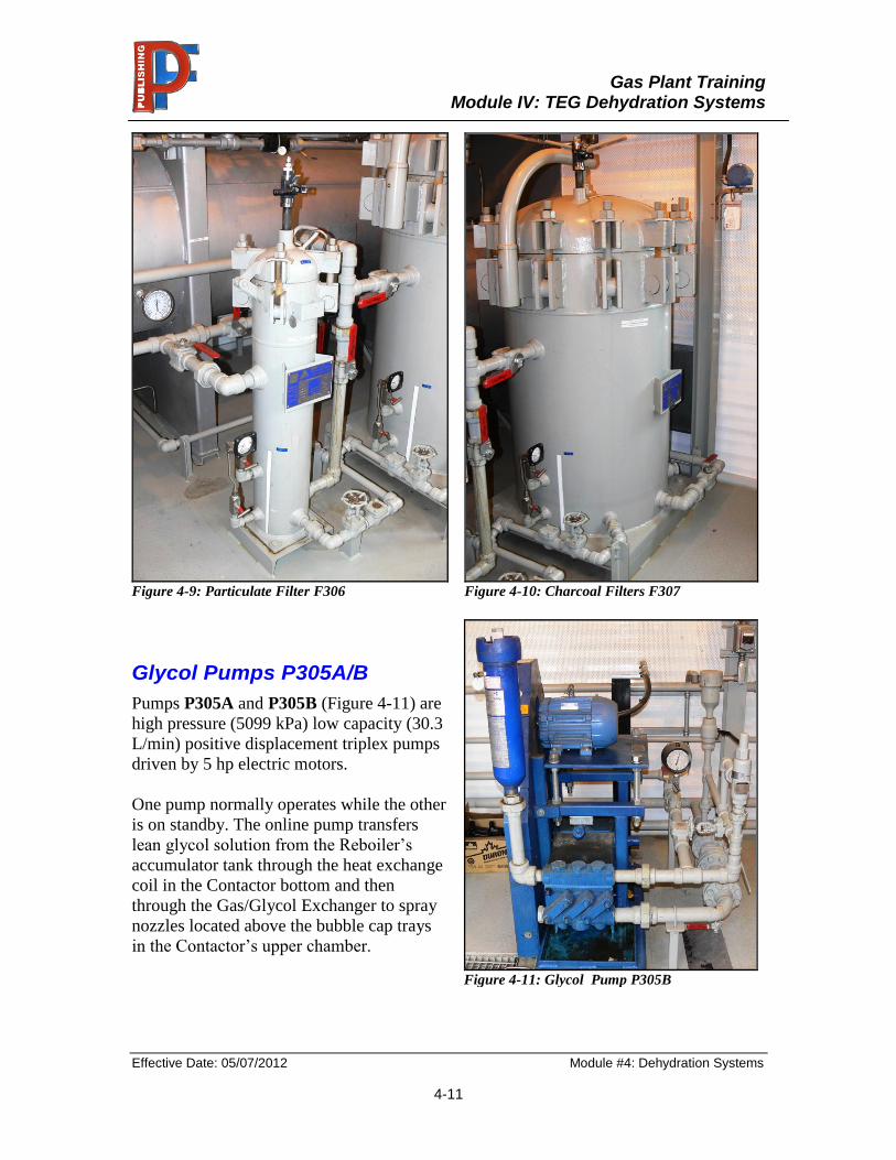
Glycol Filters F306/307
Rich glycol from the Flash Separator passes through cartridge filter F306 (Figure 4-9),
which removes dirt and debris. The filter elements must be replaced as they become
saturated with particulates. If the filter elements are not replaced, they will eventually
become completely plugged and will either stop the glycol flow or collapse and allow the
glycol to bypass the elements.
Glycol flowing through new filter elements will usually show a pressure drop of 20 to 40
kPa. As the elements pick up particles from the glycol stream, they become clogged and
the pressure drop increases. When the pressure drop reaches 100 to 140 kPa, the elements
should be replaced.
Charcoal Filter F307 (Figure 4-10) primarily removes heavy hydrocarbons.
Gas Plant Training
Module IV: TEG Dehydration Systems
Effective Date: 05/07/2012 Module #4: Dehydration Systems
4-11
Figure 4-9: Particulate Filter F306 Figure 4-10: Charcoal Filters F307
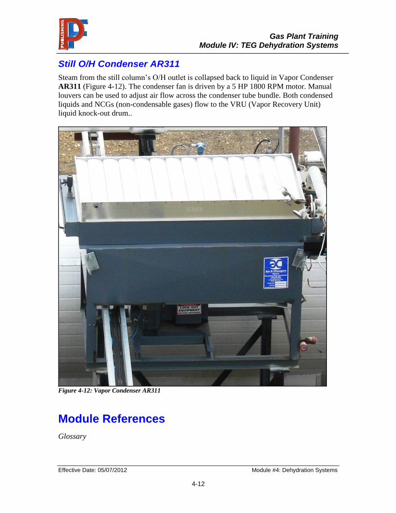
Glycol Pumps P305A/B
Pumps P305A and P305B (Figure 4-11) are
high pressure (5099 kPa) low capacity (30.3
L/min) positive displacement triplex pumps
driven by 5 hp electric motors.
One pump normally operates while the other
is on standby. The online pump transfers
lean glycol solution from the Reboiler’s
accumulator tank through the heat exchange
coil in the Contactor bottom and then
through the Gas/Glycol Exchanger to spray
nozzles located above the bubble cap trays
in the Contactor’s upper chamber.
Figure 4-11: Glycol Pump P305B
Gas Plant Training
Module IV: TEG Dehydration Systems
Effective Date: 05/07/2012 Module #4: Dehydration Systems
4-12
Still O/H Condenser AR311
Steam from the still column’s O/H outlet is collapsed back to liquid in Vapor Condenser
AR311 (Figure 4-12). The condenser fan is driven by a 5 HP 1800 RPM motor. Manual
louvers can be used to adjust air flow across the condenser tube bundle. Both condensed
liquids and NCGs (non-condensable gases) flow to the VRU (Vapor Recovery Unit)
liquid knock-out drum..
Figure 4-12: Vapor Condenser AR311
Module References
Glossary
Gas Plant Training
Module IV: TEG Dehydration Systems
Effective Date: 05/07/2012 Module #4: Dehydration Systems
4-13
Module 4 Exercises
Written Exercises ~ Self-Assessed
The following questions apply to normal conditions unless otherwise stated. From the
given choices, select the best answer to each question. Although other choices may apply
under different conditions, do not consider these choices as being the best answers. Put
your answers on a separate piece of paper. Do not write in the manual.
Multiple Choice
1. The purpose of the dehydration system is to…
a. remove water from the gas stream
b. remove hydrocarbons from the rich glycol
c. remove water from the rich glycol
d. All of the above
2. The absorption of water into glycol takes place in the…
a. Flash Separator
b. Reboiler
c. Contactor
d. Still O/H Condenser
3. The glycol Regeneration process takes place at…
a. high pressure, low temperature
b. low pressure, low temperature
c. low pressure, high temperature
d. high pressure, high temperature
4. Rich glycol leaving the Contactor is first warmed in the…
a. distillation stripping column preheat coil
b. Lean/Rich Glycol Exchanger
c. Flash Separator
d. Reboiler
Gas Plant Training
Module IV: TEG Dehydration Systems
Effective Date: 05/07/2012 Module #4: Dehydration Systems
4-14
5. Which unit boils hydrocarbons from the glycol?
b. Regenerator
c. Still O/H Condenser
d. Flash Separator
6. Rich glycol is returned to a lean state in the…
a. Flash Separator
b. Reboiler
c. Contactor
d. Still O/H Condenser
7. Which unit is responsible for cooling lean glycol just before it enters the
Contactor?
a. Glycol Filters
b. Lean/Rich Glycol Exchanger
c. Gas/Glycol Exchanger
d. Accumulator
8. Glycol pumps P305A/B transfer…
a. rich glycol from the Contactor to the Regenerator
b. lean glycol from the Regenerator to the Contactor
9. Steam from the Reboiler’s distillation column is collapsed back to vapour in the…
a. Accumulator
b. Flash Separator
c. Still O/H Condenser
d. Contactor
10. Water from the Contactor bottom transfers to the…
a. Flash Separator
b. VRU Knockout Drum
c. Regenerator
d. Produced Water Tank
Gas Plant Training
Module IV: TEG Dehydration Systems
Effective Date: 05/07/2012 Module #4: Dehydration Systems
4-15
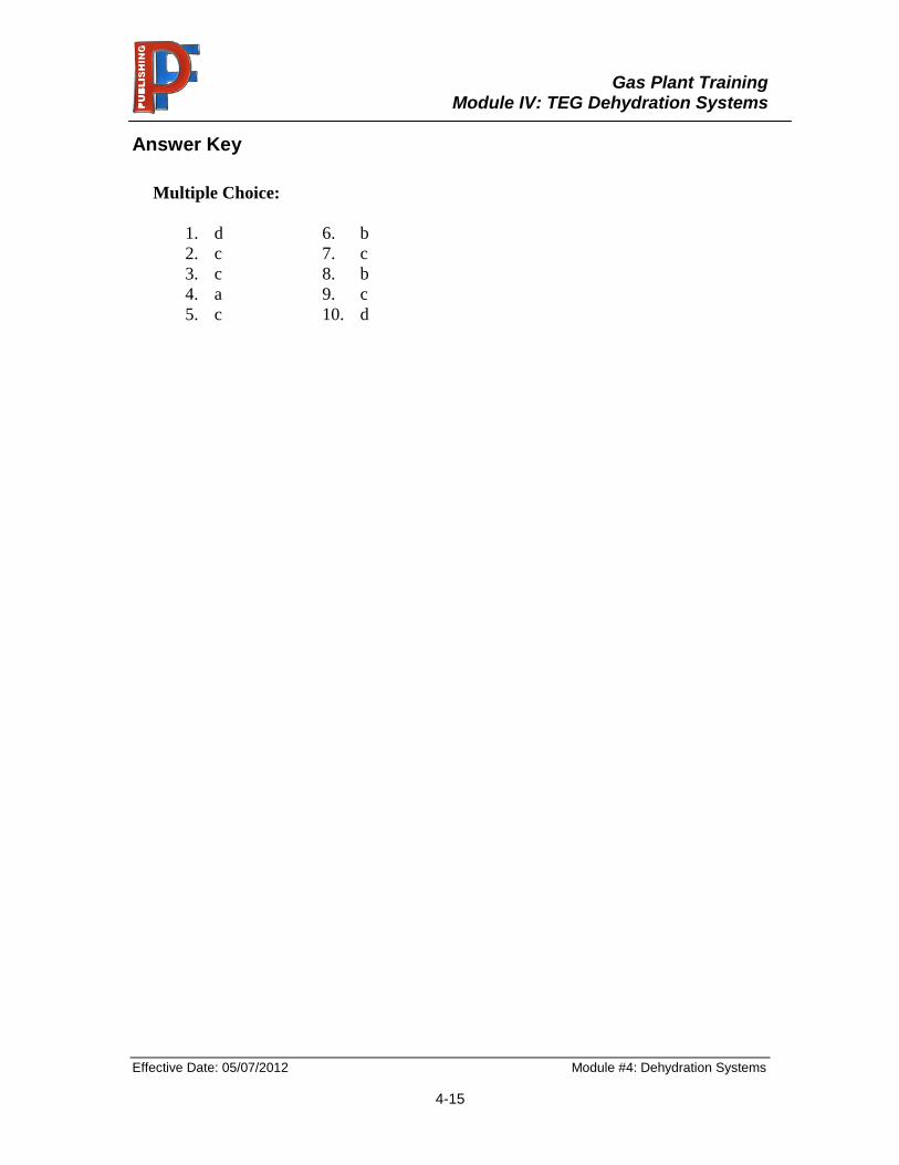
Answer Key
Multiple Choice:
1. d 6. b
2. c 7. c
3. c 8. b
4. a 9. c
5. c 10. d