g9sp series safety controller operation manualomronkft.hu/pdf_en/g9sp_opman.pdf · 2015-04-09 ·...
TRANSCRIPT

OPERATION MANUAL
Cat. No. Z922-E1-04
G9SP SeriesSafety Controller


OMRON, 2010All rights reserved. No part of this publication may be reproduced, stored in a retrieval system, or transmitted, in any form, orby any means, mechanical, electronic, photocopying, recording, or otherwise, without the prior written permission ofOMRON.
No patent liability is assumed with respect to the use of the information contained herein. Moreover, because OMRON is con-stantly striving to improve its high-quality products, the information contained in this manual is subject to change withoutnotice. Every precaution has been taken in the preparation of this manual. Nevertheless, OMRON assumes no responsibilityfor errors or omissions. Neither is any liability assumed for damages resulting from the use of the information contained inthis publication.


G9SP-series Safety Controller:
G9SP-N@@@Operation ManualRevised June 2014


TABLE OF CONTENTS
Introduction . . . . . . . . . . . . . . . . . . . . . . . . . . . . . . . . . . . . . . . . . . . . . . . . . . . . . . . . . . . . . . . . . . . . . xiManual Configuration . . . . . . . . . . . . . . . . . . . . . . . . . . . . . . . . . . . . . . . . . . . . . . . . . . . . . . . . . . . . . xii
Sections in this Manual . . . . . . . . . . . . . . . . . . . . . . . . . . . . . . . . . . . . . . . . . . . . . . . . . . . . . . . . . . . . xiii
Safety Precautions . . . . . . . . . . . . . . . . . . . . . . . . . . . . . . . . . . . . . . . . . . . . . . . . . . . . . . . . . . . . . . . . xvii
Precautions for Safe Use . . . . . . . . . . . . . . . . . . . . . . . . . . . . . . . . . . . . . . . . . . . . . . . . . . . . . . . . . . . xx
Precautions for Compliance with UL Standards and CSA Standards . . . . . . . . . . . . . . . . . . . . . . . . xxiii
Regulations and Standards . . . . . . . . . . . . . . . . . . . . . . . . . . . . . . . . . . . . . . . . . . . . . . . . . . . . . . . . . xxiv
Glossary . . . . . . . . . . . . . . . . . . . . . . . . . . . . . . . . . . . . . . . . . . . . . . . . . . . . . . . . . . . . . . . . . . . . . . . xxvi
Overview
SECTION 1Overview . . . . . . . . . . . . . . . . . . . . . . . . . . . . . . . . . . . . . . . . . 1
1-1 Overview and Features of the G9SP-series Controller . . . . . . . . . . . . . . . . . . . . . . . . . . . . . 2
1-2 Basic Operating Procedures. . . . . . . . . . . . . . . . . . . . . . . . . . . . . . . . . . . . . . . . . . . . . . . . . . 9
Hardware Settings
SECTION 2Part Names and Specifications . . . . . . . . . . . . . . . . . . . . . . . 11
2-1 G9SP-series Controllers. . . . . . . . . . . . . . . . . . . . . . . . . . . . . . . . . . . . . . . . . . . . . . . . . . . . . 12
2-2 Expansion I/O Units . . . . . . . . . . . . . . . . . . . . . . . . . . . . . . . . . . . . . . . . . . . . . . . . . . . . . . . 39
2-3 Option Units . . . . . . . . . . . . . . . . . . . . . . . . . . . . . . . . . . . . . . . . . . . . . . . . . . . . . . . . . . . . . 47
Hardware Settings
SECTION 3Calculating Response Performance . . . . . . . . . . . . . . . . . . . 51
3-1 Startup Time . . . . . . . . . . . . . . . . . . . . . . . . . . . . . . . . . . . . . . . . . . . . . . . . . . . . . . . . . . . . . 52
3-2 Reaction Times . . . . . . . . . . . . . . . . . . . . . . . . . . . . . . . . . . . . . . . . . . . . . . . . . . . . . . . . . . . 53
Hardware Settings
SECTION 4Installation and Wiring . . . . . . . . . . . . . . . . . . . . . . . . . . . . . 55
4-1 Installation . . . . . . . . . . . . . . . . . . . . . . . . . . . . . . . . . . . . . . . . . . . . . . . . . . . . . . . . . . . . . . . 56
4-2 Wiring . . . . . . . . . . . . . . . . . . . . . . . . . . . . . . . . . . . . . . . . . . . . . . . . . . . . . . . . . . . . . . . . . . 63
vii

TABLE OF CONTENTS
Software Design
SECTION 5Preparations for Using the G9SP Configurator. . . . . . . . . . 67
5-1 Overview . . . . . . . . . . . . . . . . . . . . . . . . . . . . . . . . . . . . . . . . . . . . . . . . . . . . . . . . . . . . . . . . 68
5-2 Installation . . . . . . . . . . . . . . . . . . . . . . . . . . . . . . . . . . . . . . . . . . . . . . . . . . . . . . . . . . . . . . . 70
Software Design
SECTION 6Creating Configuration Data . . . . . . . . . . . . . . . . . . . . . . . . . 79
6-1 Overview . . . . . . . . . . . . . . . . . . . . . . . . . . . . . . . . . . . . . . . . . . . . . . . . . . . . . . . . . . . . . . . . 80
6-2 Creating Configuration Data . . . . . . . . . . . . . . . . . . . . . . . . . . . . . . . . . . . . . . . . . . . . . . . . . 81
6-3 Designing Device Security . . . . . . . . . . . . . . . . . . . . . . . . . . . . . . . . . . . . . . . . . . . . . . . . . . 88
6-4 Offline Simulation . . . . . . . . . . . . . . . . . . . . . . . . . . . . . . . . . . . . . . . . . . . . . . . . . . . . . . . . . 93
6-5 Creating and Using User-defined Function Blocks . . . . . . . . . . . . . . . . . . . . . . . . . . . . . . . . 97
Software Design
SECTION 7Communications with a Standard PLC Using an Option Board103
7-1 Functionality for All Option Board's . . . . . . . . . . . . . . . . . . . . . . . . . . . . . . . . . . . . . . . . . . . 104
7-2 RS-232C Serial Communications . . . . . . . . . . . . . . . . . . . . . . . . . . . . . . . . . . . . . . . . . . . . . 115
7-3 Ethernet Communications . . . . . . . . . . . . . . . . . . . . . . . . . . . . . . . . . . . . . . . . . . . . . . . . . . . 123
Software Design
SECTION 8Connecting Online and Downloading to the G9SP-series Controller131
8-1 Overview . . . . . . . . . . . . . . . . . . . . . . . . . . . . . . . . . . . . . . . . . . . . . . . . . . . . . . . . . . . . . . . . 132
8-2 Downloading Configuration Data to the G9SP-series Controller and Verification. . . . . . . . 133
8-3 Uploading Data from the G9SP-series Controller . . . . . . . . . . . . . . . . . . . . . . . . . . . . . . . . . 135
8-4 Resetting the G9SP-series Controller . . . . . . . . . . . . . . . . . . . . . . . . . . . . . . . . . . . . . . . . . . 136
8-5 Setting a Device Password. . . . . . . . . . . . . . . . . . . . . . . . . . . . . . . . . . . . . . . . . . . . . . . . . . . 137
viii
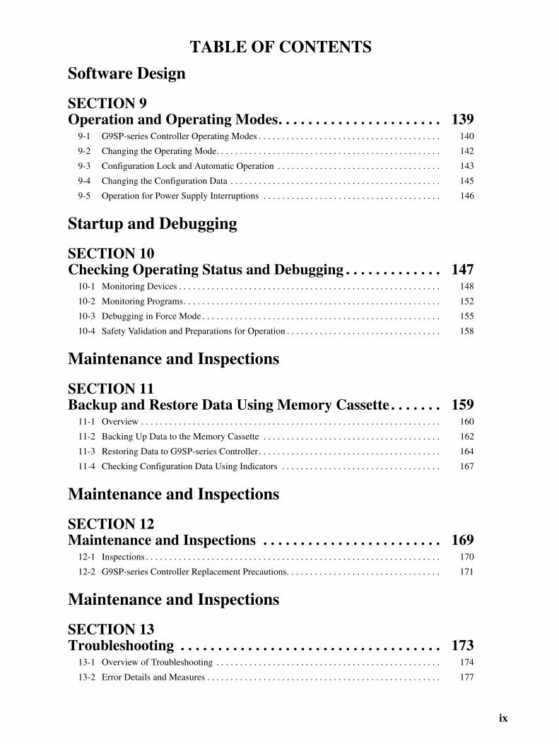
TABLE OF CONTENTS
Software Design
SECTION 9Operation and Operating Modes. . . . . . . . . . . . . . . . . . . . . . 139
9-1 G9SP-series Controller Operating Modes . . . . . . . . . . . . . . . . . . . . . . . . . . . . . . . . . . . . . . . 140
9-2 Changing the Operating Mode. . . . . . . . . . . . . . . . . . . . . . . . . . . . . . . . . . . . . . . . . . . . . . . . 142
9-3 Configuration Lock and Automatic Operation . . . . . . . . . . . . . . . . . . . . . . . . . . . . . . . . . . . 143
9-4 Changing the Configuration Data . . . . . . . . . . . . . . . . . . . . . . . . . . . . . . . . . . . . . . . . . . . . . 145
9-5 Operation for Power Supply Interruptions . . . . . . . . . . . . . . . . . . . . . . . . . . . . . . . . . . . . . . 146
Startup and Debugging
SECTION 10Checking Operating Status and Debugging . . . . . . . . . . . . . 147
10-1 Monitoring Devices . . . . . . . . . . . . . . . . . . . . . . . . . . . . . . . . . . . . . . . . . . . . . . . . . . . . . . . . 148
10-2 Monitoring Programs. . . . . . . . . . . . . . . . . . . . . . . . . . . . . . . . . . . . . . . . . . . . . . . . . . . . . . . 152
10-3 Debugging in Force Mode . . . . . . . . . . . . . . . . . . . . . . . . . . . . . . . . . . . . . . . . . . . . . . . . . . . 155
10-4 Safety Validation and Preparations for Operation . . . . . . . . . . . . . . . . . . . . . . . . . . . . . . . . . 158
Maintenance and Inspections
SECTION 11Backup and Restore Data Using Memory Cassette . . . . . . . 159
11-1 Overview . . . . . . . . . . . . . . . . . . . . . . . . . . . . . . . . . . . . . . . . . . . . . . . . . . . . . . . . . . . . . . . . 160
11-2 Backing Up Data to the Memory Cassette . . . . . . . . . . . . . . . . . . . . . . . . . . . . . . . . . . . . . . 162
11-3 Restoring Data to G9SP-series Controller. . . . . . . . . . . . . . . . . . . . . . . . . . . . . . . . . . . . . . . 164
11-4 Checking Configuration Data Using Indicators . . . . . . . . . . . . . . . . . . . . . . . . . . . . . . . . . . 167
Maintenance and Inspections
SECTION 12Maintenance and Inspections . . . . . . . . . . . . . . . . . . . . . . . . 169
12-1 Inspections . . . . . . . . . . . . . . . . . . . . . . . . . . . . . . . . . . . . . . . . . . . . . . . . . . . . . . . . . . . . . . . 170
12-2 G9SP-series Controller Replacement Precautions. . . . . . . . . . . . . . . . . . . . . . . . . . . . . . . . . 171
Maintenance and Inspections
SECTION 13Troubleshooting . . . . . . . . . . . . . . . . . . . . . . . . . . . . . . . . . . . 173
13-1 Overview of Troubleshooting . . . . . . . . . . . . . . . . . . . . . . . . . . . . . . . . . . . . . . . . . . . . . . . . 174
13-2 Error Details and Measures . . . . . . . . . . . . . . . . . . . . . . . . . . . . . . . . . . . . . . . . . . . . . . . . . . 177
ix

TABLE OF CONTENTS
AppendicesApplication Templates . . . . . . . . . . . . . . . . . . . . . . . . . . . . . . 181
A Using the Password Recovery Tool . . . . . . . . . . . . . . . . . . . . . . . . . . . . . . . . . . . . . . . . . . . 199
B Calculated Values of PFD and PFH . . . . . . . . . . . . . . . . . . . . . . . . . . . . . . . . . . . . . . . . . . . 201
C Version-related Information . . . . . . . . . . . . . . . . . . . . . . . . . . . . . . . . . . . . . . . . . . . . . . . . . 203
Index. . . . . . . . . . . . . . . . . . . . . . . . . . . . . . . . . . . . . . . . . . . . . 207
Revision History . . . . . . . . . . . . . . . . . . . . . . . . . . . . . . . . . . . 209
x

Introduction
Thank you for purchasing a G9SP-series Safety Controller. This manual contains information required touse the G9SP-series Controller. Please thoroughly read and understand this manual before you use theG9SP-series Controller.
This manual is intended for the following personnel, who must also have knowledge of electrical systems(an electrical engineer or the equivalent).
• Personnel in charge of installing FA systems.
• Personnel in charge of designing FA systems.
• Personnel in charge of managing FA systems and facilities.
• Personnel in charge of qualifications and authority in all phases, including system design, installation,operation, maintenance, and disposal.
Intended Audience
xi
Manual Configuration
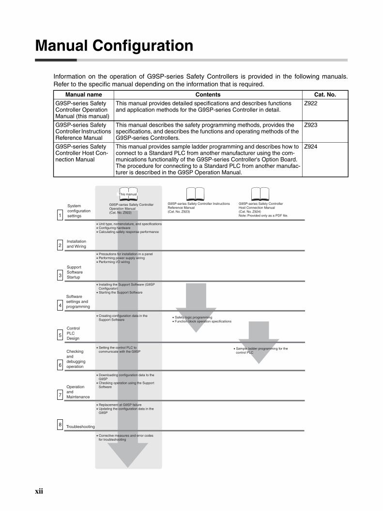
Information on the operation of G9SP-series Safety Controllers is provided in the following manuals.Refer to the specific manual depending on the information that is required.
Manual name Contents Cat. No.
G9SP-series Safety Controller Operation Manual (this manual)
This manual provides detailed specifications and describes functions and application methods for the G9SP-series Controller in detail.
Z922
G9SP-series Safety Controller Instructions Reference Manual
This manual describes the safety programming methods, provides the specifications, and describes the functions and operating methods of the G9SP-series Controllers.
Z923
G9SP-series Safety Controller Host Con-nection Manual
This manual provides sample ladder programming and describes how to connect to a Standard PLC from another manufacturer using the com-munications functionality of the G9SP-series Controller's Option Board. The procedure for connecting to a Standard PLC from another manufac-turer is described in the G9SP Operation Manual.
Z924
1
2
3
4
5
6
7
8
G9SP-series Safety Controller Operation Manual (Cat. No. Z922)
G9SP-series Safety Controller Instructions Reference Manual (Cat. No. Z923)
• Precautions for installation in a panel• Performing power supply wiring • Performing I/O wiring
• Unit type, nomenclature, and specifications• Configuring hardware • Calculating safety response performance
G9SP-series Safety Controller Host Connection Manual (Cat. No. Z924) Note: Provided only as a PDF file.
Troubleshooting
• Safety logic programming • Function block operation specifications
System configuration settings
Installation and Wiring
Support Software Startup
Software settings and programming
Control PLC Design
Checking and debugging operation
Operation and Maintenance
• Sample ladder programming for the control PLC
• Installing the Support Software (G9SP Configurator)
• Starting the Support Software
• Creating configuration data in the Support Software
• Setting the control PLC to communicate with the G9SP
• Downloading configuration data to the G9SP
• Checking operation using the Support Software
• Replacement at G9SP failure• Updating the configuration data in the
G9SP
• Corrective measures and error codes for troubleshooting
This manual
xii

Sections in this Manual
1 10
2 11
3 12
4
5
6
7
8
9
Overview
Application Templates
Part Names and Specifications
Calculating Response Performance
Installation and Wiring
Preparations for Using the G9SP Configurator
Creating Configuration Data
Communications with a Standard PLC Using an Option Board
Connecting Online and Downloading to the G9SP-series Controller
Operation and Operating Modes
Checking Operating Status and Debugging
Backup and Restore Data Using Memory Cassette
Maintenance and Inspections
Troubleshooting13
A
xiii

xiv
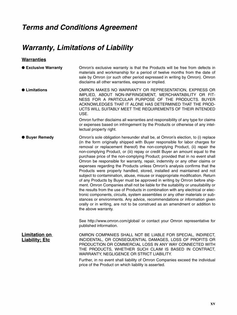
Terms and Conditions Agreement
Warranty, Limitations of Liability
Warranties
Exclusive Warranty Omron’s exclusive warranty is that the Products will be free from defects inmaterials and workmanship for a period of twelve months from the date ofsale by Omron (or such other period expressed in writing by Omron). Omrondisclaims all other warranties, express or implied.
Limitations OMRON MAKES NO WARRANTY OR REPRESENTATION, EXPRESS ORIMPLIED, ABOUT NON-INFRINGEMENT, MERCHANTABILITY OR FIT-NESS FOR A PARTICULAR PURPOSE OF THE PRODUCTS. BUYERACKNOWLEDGES THAT IT ALONE HAS DETERMINED THAT THE PROD-UCTS WILL SUITABLY MEET THE REQUIREMENTS OF THEIR INTENDEDUSE.
Omron further disclaims all warranties and responsibility of any type for claimsor expenses based on infringement by the Products or otherwise of any intel-lectual property right.
Buyer Remedy Omron’s sole obligation hereunder shall be, at Omron’s election, to (i) replace(in the form originally shipped with Buyer responsible for labor charges forremoval or replacement thereof) the non-complying Product, (ii) repair thenon-complying Product, or (iii) repay or credit Buyer an amount equal to thepurchase price of the non-complying Product; provided that in no event shallOmron be responsible for warranty, repair, indemnity or any other claims orexpenses regarding the Products unless Omron’s analysis confirms that theProducts were properly handled, stored, installed and maintained and notsubject to contamination, abuse, misuse or inappropriate modification. Returnof any Products by Buyer must be approved in writing by Omron before ship-ment. Omron Companies shall not be liable for the suitability or unsuitability orthe results from the use of Products in combination with any electrical or elec-tronic components, circuits, system assemblies or any other materials or sub-stances or environments. Any advice, recommendations or information givenorally or in writing, are not to be construed as an amendment or addition tothe above warranty.
See http://www.omron.com/global/ or contact your Omron representative forpublished information.
Limitation on Liability; Etc
OMRON COMPANIES SHALL NOT BE LIABLE FOR SPECIAL, INDIRECT,INCIDENTAL, OR CONSEQUENTIAL DAMAGES, LOSS OF PROFITS ORPRODUCTION OR COMMERCIAL LOSS IN ANY WAY CONNECTED WITHTHE PRODUCTS, WHETHER SUCH CLAIM IS BASED IN CONTRACT,WARRANTY, NEGLIGENCE OR STRICT LIABILITY.
Further, in no event shall liability of Omron Companies exceed the individualprice of the Product on which liability is asserted.
xv
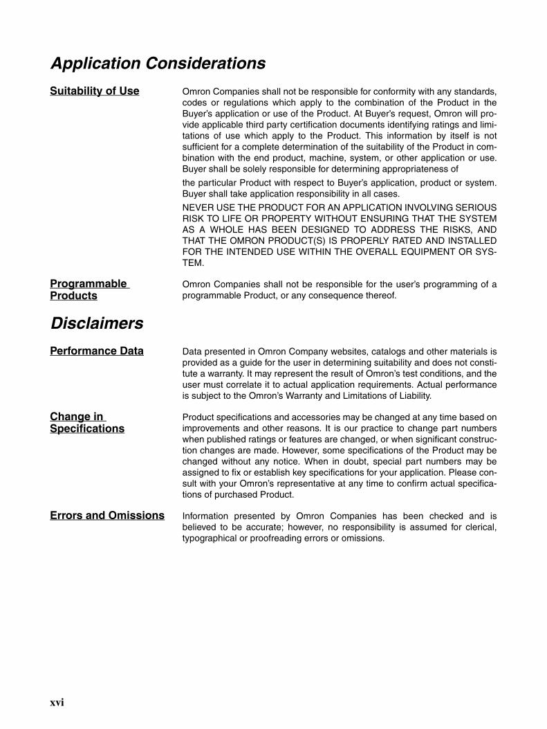
Application Considerations
Suitability of Use Omron Companies shall not be responsible for conformity with any standards,codes or regulations which apply to the combination of the Product in theBuyer’s application or use of the Product. At Buyer’s request, Omron will pro-vide applicable third party certification documents identifying ratings and limi-tations of use which apply to the Product. This information by itself is notsufficient for a complete determination of the suitability of the Product in com-bination with the end product, machine, system, or other application or use.Buyer shall be solely responsible for determining appropriateness of
the particular Product with respect to Buyer’s application, product or system.Buyer shall take application responsibility in all cases.
NEVER USE THE PRODUCT FOR AN APPLICATION INVOLVING SERIOUSRISK TO LIFE OR PROPERTY WITHOUT ENSURING THAT THE SYSTEMAS A WHOLE HAS BEEN DESIGNED TO ADDRESS THE RISKS, ANDTHAT THE OMRON PRODUCT(S) IS PROPERLY RATED AND INSTALLEDFOR THE INTENDED USE WITHIN THE OVERALL EQUIPMENT OR SYS-TEM.
Programmable Products
Omron Companies shall not be responsible for the user’s programming of aprogrammable Product, or any consequence thereof.
Disclaimers
Performance Data Data presented in Omron Company websites, catalogs and other materials isprovided as a guide for the user in determining suitability and does not consti-tute a warranty. It may represent the result of Omron’s test conditions, and theuser must correlate it to actual application requirements. Actual performanceis subject to the Omron’s Warranty and Limitations of Liability.
Change in Specifications
Product specifications and accessories may be changed at any time based onimprovements and other reasons. It is our practice to change part numberswhen published ratings or features are changed, or when significant construc-tion changes are made. However, some specifications of the Product may bechanged without any notice. When in doubt, special part numbers may beassigned to fix or establish key specifications for your application. Please con-sult with your Omron’s representative at any time to confirm actual specifica-tions of purchased Product.
Errors and Omissions Information presented by Omron Companies has been checked and isbelieved to be accurate; however, no responsibility is assumed for clerical,typographical or proofreading errors or omissions.
xvi

Safety Precautions
The following notation is used in this manual to provide precautions required to ensure safe usage of aG9SP-series Controller. The safety precautions that are provided are extremely important to safety.Always read and heed the information provided in all safety precautions.
The keywords and their definitions are as given below.
Definition of Precautionary Information
WARNINGIndicates a potentially hazardous situation which, if not avoided, will result in minor or moderate injury, or may result in serious injury or death. Additionally there may be significant property damage.
CautionIndicates a potentially hazardous situation which, if not avoided, may result in minor or moderate injury or in property damage.
Precautions for Safe UseIndicates precautions on what to do and what not to do to ensure using the product safely.
Precautions for Correct UseIndicates precautions on what to do and what not to do to ensure proper operation and performance.
Symbols
The circle and slash symbol indicates operations that you must not do.The specific operation is shown in the circle and explained in text.
The filled circle symbol indicates operations that you must do. The specific operation is shown in the circle and explained in text. This example shows a general precaution for something that you must do.
xvii

WARNINGThis is the Operation Manual for the G9SP-series Safety Controllers.
Obey the following warnings during system construction to ensure that safety-related components are configured to enable the system functions to sufficiently operate.
Risk AssessmentThe proper use of the safety devices described in this manual as they relate to installation conditions and mechanical performance and functions is a prerequisite for its use.
When selecting or using the safety devices, risk assessment must be performed during the development stage of the equipment or facilities to identify potential danger factors in equipment or facilities in which the safety devices are to be applied. Suitable safety devices must be selected under the guidance of a sufficient risk assessment system. An insuf-ficient risk assessment system may result in the selection of unsuitable safety devices.
• Typical related international standards: ISO 14121, Safety of Machinery -- Principles of Risk Assessment
Safety MeasuresWhen using this safety device to build systems containing safety-related components for equipment or facilities, the system must be designed with the full understanding of and conformance to international standards, such as those listed below, and/or standards in related industries.
• Typical related international standards: ISO/DIS 12100, Safety of Machinery -- Basic Concepts and General Principles for Design
IEC 61508, Safety Standard for Safety Instrumented Systems (Functional Safety of Electrical/Elec-tronic/Programmable Electronic Safety-related Systems)
Role of Safety DevicesThe safety devices are provided with safety functions and mechanisms as stipulated in relevant standards, but suitable designs must be used to enable these functions and mechanisms to operate properly inside system constructions con-taining safety-related components. Build systems that enable these functions and mechanisms to perform properly, based on a full understanding of their operation.
• Typical related international standards: ISO 14119, Safety of machinery -- Interlocking devices associated with guards -- Principles for design and selection
Installation of Safety DevicesThe construction and installation of systems with safety-related components for equipment or facilities must be per-formed by technicians who have received suitable training.
• Typical related international standards: ISO/DIS 12100, Safety of Machinery -- Basic Concepts and General Principles for Design
IEC 61508, Safety Standard for Safety Instrumented Systems (Functional Safety of Electrical/Elec-tronic/Programmable Electronic Safety-related Systems)
Compliance with Laws and RegulationsThis safety device conforms to the relevant regulations and standards, but make sure that it is used in compliance with local regulations and standards for the equipment or facilities in which it is applied.
• Typical related international standards: IEC 60204, Safety of Machinery -- Electrical Equipment of Machines
Observing Precautions for UseWhen putting the selected safety device to actual use, heed the specifications and precautions in this manual and those in the instruction manual that comes with the product. Using a product in a manner that deviates from these specifications and precautions will lead to unexpected failures in equipment or devices, and to damage that results from such failures, due to insufficient operating functions in safety-related components.
Moving or Transferring Devices or EquipmentWhen moving or transferring devices or equipment, be sure to include this manual to ensure that the person to whom the device or equipment is being moved or transferred will be able to operate it properly.
• Typical related international standards: ISO/DIS 12100, Safety of Machinery -- Basic Concepts and General Principles for Design
IEC 61508, Safety Standard for Safety Instrumented Systems (Functional Safety of Electrical/Elec-tronic/Programmable Electronic Safety-related Systems)
xviii

WARNINGElectric shock may occur. Do not touch any terminals while power is being supplied.
Serious injury may possibly occur due to loss of required safety functions. Do not use the G9SP-series Controller's test outputs or standard outputs as safety outputs.
Serious injury may possibly occur due to loss of required safety functions. Do not use the G9SP-series Controller's network data as safety data.
Serious injury may possibly occur due to loss of required safety functions. Do not use indica-tors on the G9SP-series Controller for safety operations.
Serious injury may possibly occur due to breakdown of safety outputs or test outputs. Do not connect loads beyond the rated values to the safety outputs and test outputs.
Serious injury may possibly occur due to loss of required safety functions. Wire the G9SP-series Controller properly so that the 24VDC line does NOT touch the outputs accidentally or unintentionally.
Serious injury may possibly occur due to loss of required safety functions. Ground the 0V line of the power supply for external output devices so that the devices do NOT turn ON when the safety output line or the test output line is grounded.
Serious injury may possibly occur due to loss of required safety functions. Perform user testing and confirm that all of the G9SP-series Controller’s configuration data and operation is correct before starting system operation.
Serious injury may possibly occur due to loss of required safety functions. When replacing a G9SP-series Controller, confirm the model of the Controller is correct and configure the replacement Controller suitably and confirm that it operates correctly.
Serious injury may possibly occur due to loss of required safety functions. Once the data has been restored from the Memory Cassette, check that the configuration data of the G9SP-series Controller is correct in that it operates properly and carry out the validation testing (User Test-ing).
Outputs may operate, possibly resulting in serious injury. Take sufficient safety measures before force-setting or force-resetting variables in the program.
Serious injury may possibly occur due to loss of required safety functions. Use devices and parts related to safety functions according to legal regulations in the applicable country. Use certified items compliant with safety standards corresponding to the intended application.
xix

Precautions for Safe Use
HandlingDo not drop the G9SP-series Controller or subject it to excessive vibration or mechanical shock. TheG9SP-series Controller may be damaged and may not function properly.
Installation and Storage EnvironmentDo not use or store the G9SP-series Controller in any of the following locations:
• Locations subject to direct sunlight• Locations subject to temperatures or humidity outside the range specified in the
specifications• Locations subject to condensation as the result of severe changes in temperature• Locations subject to corrosive or flammable gases• Locations subject to dust (especially iron dust) or salts• Locations subject to water, oil, or chemicals• Locations subject to shock or vibration
Take appropriate and sufficient measures when installing systems in the following locations. Inappropri-ate and insufficient measures may result in malfunction.
• Locations subject to static electricity or other forms of noise• Locations subject to strong electromagnetic fields• Locations subject to possible exposure to radioactivity• Locations close to power supplies
This is a class A product designed for use in industrial environments. In residential areas it may causeradio interference, in which case the user may be required to take adequate measures to reduce interfer-ence.
Installation and Mounting• Use the G9SP-series Controller within an enclosure with IP54 protection or higher according to IEC/
EN 60529.• Use DIN Track (TH35-7.5/TH35-15 according to IEC 60715) or M4 screws with a tightening torque of
1.2 N·m (10.5 lb·in) to install the G9SP-series Controller into the control panel.• Mount the G9SP-series Controller to the DIN Track using PFP-M End Plates (not included with the
G9SP-series Controller) to prevent it from falling off the DIN Track because of vibration. Correctlymount all Units to DIN Track.
• Install the G9SP-series Controller in the vertical direction shown below to ensure adequate cooling.
• Space must be provided around the G9SP-series Controller, at least 20 mm from its side surfaces andat least 50 mm from its top and bottom surfaces, for ventilation, wiring and Unit replacement.
• Be sure to lock all locking mechanisms, such as those on I/O terminal blocks and connectors, beforeattempting to use the G9SP-series Controller.
xx

Turn OFF the power supply before performing any of the following.
• Connecting or disconnecting Expansion I/O Units, Option Boards, or any other Units• Assembling the G9SP-series Controller• Connecting cables or wiring• Connecting or removing terminal blocks
Installation and Wiring• Use the following to wire external I/O devices to the G9SP-series Controller.
*1: When wiring two wires to one terminal. Use two wires of the same type and thickness.
• M3 self-rising screws are used for all screw terminals.• Tighten the terminal block screws to a torque of 0.5 N·m (4.4 lb·in).• Disconnect the G9SP-series Controller from the power supply before starting wiring. Devices con-
nected to the G9SP-series Controller may operate unexpectedly.• Properly apply the specified voltage to the G9SP-series Controller inputs. Applying an inappropriate
DC voltage or any AC voltage will cause the G9SP-series Controller to fail.• Be sure to separate the communications cables and I/O cables from high-voltage/high-current lines.• Be cautious not to get your fingers caught when attaching connectors to the plugs on the G9SP-series
Controller.• Incorrect wiring may lead to loss of safety functions. Wire conductors correctly and verify the operation
of the G9SP-series Controller before using the system in which the G9SP-series Controller is incorpo-rated.
• Lock the connectors on Option Units or Expansion I/O Units before using the Units.• After wiring is completed, be sure to remove the label for wire clip entry prevention from the G9SP-
series Controller to enable heat to escape for proper cooling.• Do not ground the 24-V side of the power supply to the G9SP-series Controller. If you do so, an
unwanted current flow shown in the following diagram may occur when you connect a computer orother peripheral device.
• Connect no more than the specified number of Expansion I/O Units.
Solid wire 0.32 to 0.82 mm2 AWG22 to AWG18
0.32 to 0.5 mm2 AWG22 to AWG20*1
Stranded wire 0.5 to 1.3 mm2 AWG20 to AWG16
0.5 to 0.82 mm2 AWG20 to AWG18*1
Power supply circuit
24 V
0 V 0 V 0 V
Peripheral device
USB cable
FG
G9SP
GND
xxi

Power Supply SelectionUse a DC power supply satisfying the following requirements.
• The secondary circuit of the DC power supply must be isolated from the primary cir-cuit by double insulation or reinforced insulation.
• The output characteristic requirements defined in UL 508 for class 2 circuits or con-trol voltage current circuits are satisfied.
• The output hold time must be 20 ms or longer.• The DC power supply must be an SELV power supply that satisfies the requirements
of IEC/EN 60950-1 and EN 50178.
Periodic Inspections and Maintenance• Disconnect the G9SP-series Controller from the power supply before replacing the Controller. Devices
connected to the G9SP-series Controller may operate unexpectedly.• Do not disassemble, repair, or modify the G9SP-series Controller. Doing so may lead to loss of safety
functions.
DisposalBe cautious not to injure yourself when dismantling the G9SP-series Controller.
xxii

Precautions for Compliance with UL Standards and CSA Standards
Use the following installation information instead of the general information in the instruction manual inorder to use the product under certified conditions of UL and CSA when the product is installed in theUSA or Canada. These conditions are required by NFPA 70 (National Electrical Code in the USA) andPart 1 of the Canadian Electrical Code in Canada and may vary from information given in the productmanuals or safety precautions. G9SP-series Controllers have not been evaluated by UL as Programma-ble Safety Controllers, and the Safety functions of these devices have not been evaluated by UL as well.
• Surrounding air temperature: 55°C• Do not use crimp terminals for field wiring.• The DC power supply must satisfy the requirements for an isolated power supply
with external 8 A overcurrent protection.• Do not use the +5 V output from the CP1W-CIF01 for anything other than the NT-
AL001.• A G9SP-series Controller has two sets of power supply terminals, one for the main
power and one for I/O power. Connect both of them to the same power source.Ratings
TERMINAL MARKINGS
Controller Rating for UL
G9SP-N20S Source: 24 V dc, 500 mA, isolated sourceInput: 24 V dc, 6 mA /P, 20 pointsOutput: 24 V dc (GEN) (P.D.), 0.8 A /P, 8 points
Rated total currents of So0 to 3, So4 to 7 are 1.6 A eachTest Output:
T0 − T2: 24 V dc (GEN), 100 mAT3: 24 V dc (GEN)(TUN), 300 mAT4, T5: 24 V dc (GEN), 30 mARated total currents of T0 − T2, T4 and T5 are 120 mA
G9SP-N10D Source: 24 V dc, 500 mA, isolated sourceInput: 24 V dc, 6 mA, 10 pointsOutput: 24 V dc (GEN) (P.D.), 0.8 A /P, 16 points
Rated total currents of So0 to 3, So4 to 7, So8 to 11, So12 to So15 are 1.2 A eachTest Output:
T0 − T2: 24 V dc (GEN), 60 mAT3: 24 V dc (GEN)(TUN), 300 mAT4, T5: 24 V dc (GEN), 30 mARated total currents of T0 − T2, T4 and T5 are 60 mA
G9SP-N10S Source: 24 V dc, 400 mA, isolated sourceInput: 24 V dc, 6 mA /P, 10 pointsOutput: 24 V dc (GEN) (P.D.), 0.8 A /P, 1.6 A /Unit, 4 pointsTest Output:
T0, T1: 24 V dc (GEN), 60 mAT2: 24 V dc (GEN), 30 mAT3: 24 V dc (GEN)(TUN), 300 mARated total currents of T0 − T2 are 60 mA
Standard Output: 24 V dc (GEN), 100 mA, 4 points
Terminals Function
V1/G1 Power supply terminals for Internal/Input circuits (24 VDC).
V2/G2 Power supply terminals for output circuits (24 VDC).
NC Not used (Do not connect)
Si0 to Si19 Input terminals
T0 to T5 Test output terminals
So0 to So15 Output terminals
O0 to O3 Standard output terminals
xxiii

Regulations and Standards
The G9SP-series Controller has obtained certification for the following standards.
*1 The G9SP-series Controller (version 1.1 or later) and the Expansion I/O Units have been certified forthe KOSHA S Mark.
Using a G9SP-series Controller enables building a safety control system that satisfy the following:
• Requirements for SIL 3 (Safety Integrity Level 3) in IEC 61508, IEC/EN 62061,Safety Standard for Safety Instrumented Systems (Functional Safety of Electrical/Electronic/Programmable Electronic Safety-related Systems)
• Requirements for PLe (Performance Level e) and for safety category 4 in ENISO13849-1
• EMC Directive (2004/108/EC)• Machinery Directive (2006/42/EC)
EMC DirectiveOMRON electrical devices are built into other components or equipment. OMRON therefore pursuescompliance with the related EMC standards so that they can be more easily built into other devices orthe equipment.*
OMRON cannot confirm compliance in the customer's actual application, however, because the cus-tomer may use a variety of components and equipment, and EMC performance depends on the configu-ration, wiring, and arrangement of the equipment and control panel into which a product applicable toEC Directives is incorporated. Therefore, whether the products conform to the standards in the systemused by the customer must be checked by the customer.
* Applicable EMC (Electromagnetic Compatibility) standards are as follows: EN 61000-6-2 for EMS (Electromagnetic Susceptibility) and EN 61000-6-4 for Electro-magnetic Interference (10-m regulations applied for EN 61000-6-4 radiated emis-sion).
Certifying body Standards
TÜV Rheinland • EN ISO 13849-1:2008• EN ISO 13849-2:2008• IEC 61508 parts 1-7:2010• IEC/EN 62061:2005• IEC 61131-2:2007• EN ISO 13850:2008(EN418:1992)
• EN 60204-1:2006• EN 61000-6-2:2005• EN 61000-6-4:2007• NFPA 79-2007• ANSI RIA 15.06-1999• ANSI B11.19-2003• UL1998
UL • UL508 • CSA22.2 No.142
KOSHA • S Mark*1
Others • CE Marking• C-Tick mark
Compliance with EC Directives
Applicable Directives
Concepts
xxiv

Machinery Directive The Machinery Directive requires ensuring the required safety for safety components used for machin-ery safety.
Applicable standards: EN ISO 13849-1:2008 and IEC/EN 62061 SIL CL3
Conformance to EC DirectivesThe G9SP-series Controller complies with EC Directives. To ensure that the machine or device in whichthe G9SP-series Controller is used complies with EC Directives, the following requirements must bemet.
• Make sure that the DC power supply connected to a DC Power Supply Unit or I/OUnit satisfies the following conditions.
• There is double insulation or reinforced insulation between the primary cir-cuit and secondary circuit.
• An isolated power supply that is limited to a current of 8 A or lower must beused.
• The output hold time is 20 ms min. • The power supply is a SELV power supply that satisfies requirements in IEC/
EN 60950-1 and EN 50178. • G9SP-series products that comply with the EC Directives also comply with the
Generic Emission Standard (EN 61000-6-4) for EMI. The radiated emission charac-teristics (10-m regulations), however, may depend on the configuration of the controlpanel that is used and the relation to and wiring with other connected devices. Eventhrough the G9SP-series Controller complies with EC Directives, the customer mustconfirm that the overall machinery and equipment in which the G9SP-series Control-ler is used complies with the EC Directives.
EN ISO 13849-1 and IEC/EN 62061 require process management to avoid system interference and tosimplify reading, understanding, testing, and maintaining software. This is required in all phases of thelife cycle of software programming and software design (e.g., basic software design, safety circuit sys-tem design, and software upgrades) in safety control systems to be developed using safety controllers.Therefore, process management is required for design and development of software for facilities andequipment that use the function blocks provided in the Safety Controller.
The customer must implement measures to ensure compliance with these standards.
Windows is a registered trademark of Microsoft Corporation.
Other system names and product names in this manual are the trademarks or registered trademarks oftheir respective companies.
EN ISO 13849-1 and IEC/EN 62061 Compliance
Registered Trademarks
xxv

Glossary
The following terms are used in this manual to describe the function blocks of the G9SP-series SafetyControllers.
Terminology
Term Definition
Safety Describes a device, function, data, or other element for which special safety measures have been implemented for use in Safety Controls.
Standard Describes a device, function, data, or other element that is used in Standard Controls. Used to differentiate from devices, functions, data, or other elements for which special safety measures have been implemented for use in Safety Controls.
Safety Controller A highly reliable controller that is used in Safety Controls.
Standard PLC A programmable controller (PLC) that is used for general controls.
Used to differentiate from a PLC used for Safety Controls.
Expansion I/O Unit The name of the CP1W-20EDT(-1) and CP1W-32ET(-1).
Some of the OMRON CP1-series Expansion I/O Units can be used in a G9SP-series Controller. Expansion I/O Units are connected to a G9SP-series Controller to increase the number of Standard I/O points.
Option Board The name of the CP1W-CIF01 and CP1W-CIF41.
Some of the OMRON CP1-series Option Boards can be used in a G9SP-series Control-ler. An Option Board can be mounted in a G9SP-series Controller to communicate with a Standard PLC.
Memory Cassette The name of the CP1W-ME05M.
This OMRON CP1@-series Memory Cassette can be used in a G9SP-series Controller. It is used to back up and restore configuration data in G9SP-series Controllers.
G9SP Configurator The name of the WS02-G9SP@@.
Support Software that is used to set up, program, and debug G9SP-series Controllers.
configuration data Setup data that is used to operate a G9SP-series Controller. The configuration data is created with the G9SP Configurator and then downloaded from the computer to memory in the G9SP-series Controller. The configuration data contains the unit configuration set-tings, I/O terminal settings, system settings, and Safety Program. Refer to SECTION 6 Creating Configuration Data for details.
backup An operation used to write the configuration data stored in internal memory in the G9SP-series Controller to a Memory Cassette.
restore An operation used to write the configuration data stored in a Memory Cassette to internal memory in the G9SP-series Controller.
Safety Input Device An input device for which special safety measures have been implemented for use in Safety Controls. Safety Input Device is therefore a generic term for input devices such as emergency stop switches and safety door switches.
Safety Output Device An output device for which special safety measures have been implemented for use in Safety Controls. Safety Output Device is therefore a generic term for output devices such as safety relays.
CP Series A series of programmable controllers manufactured by OMRON.
NE1A Series A series of Safety Network Controllers manufactured by OMRON. NE1A-series Control-lers are high-end controllers in comparison to the G9SP-series Controllers.
dual channels Two channels that are used for redundancy with Safety Inputs or Safety Outputs. If the two channels must have the same value, they are called equivalent dual channels. If they must have the opposite values, they are called complementary dual channels.
discrepancy The state in which the status of two dual channels do not agree, resulting in a discrep-ancy error.
xxvi
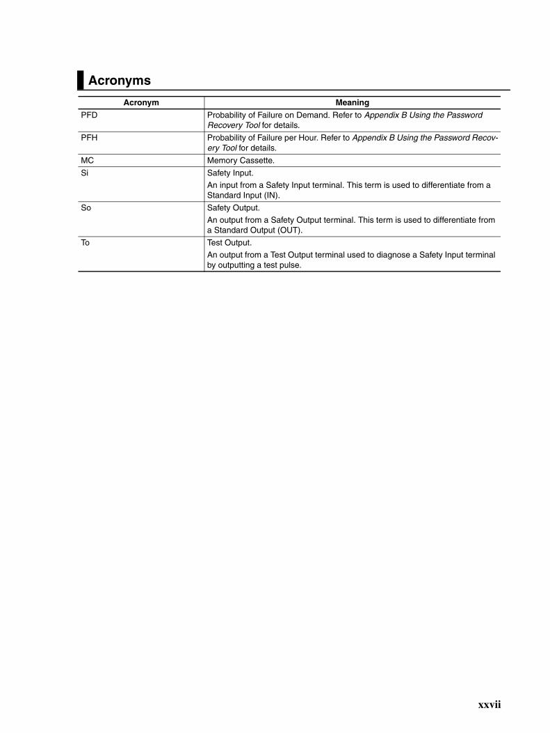
Acronyms
Acronym Meaning
PFD Probability of Failure on Demand. Refer to Appendix B Using the Password Recovery Tool for details.
PFH Probability of Failure per Hour. Refer to Appendix B Using the Password Recov-ery Tool for details.
MC Memory Cassette.
Si Safety Input.
An input from a Safety Input terminal. This term is used to differentiate from a Standard Input (IN).
So Safety Output.
An output from a Safety Output terminal. This term is used to differentiate from a Standard Output (OUT).
To Test Output.
An output from a Test Output terminal used to diagnose a Safety Input terminal by outputting a test pulse.
xxvii

xxviii
Overview
SECTION 1Overview
This section provides an overview and describes the features, system configuration, and application procedures for theG9SP-series Controller.
1-1 Overview and Features of the G9SP-series Controller . . . . . . . . . . . . . . . . . . 2
1-1-1 Overview. . . . . . . . . . . . . . . . . . . . . . . . . . . . . . . . . . . . . . . . . . . . . . 2
1-1-2 Basic System and Configuration Devices. . . . . . . . . . . . . . . . . . . . . 2
1-1-3 Features. . . . . . . . . . . . . . . . . . . . . . . . . . . . . . . . . . . . . . . . . . . . . . . 5
1-2 Basic Operating Procedures . . . . . . . . . . . . . . . . . . . . . . . . . . . . . . . . . . . . . . 9
1

Overview and Features of the G9SP-series Controller Section 1-1
1-1 Overview and Features of the G9SP-series Controller
1-1-1 OverviewThe G9SP-series Safety Controller is a programmable controller that isdesigned for easy operation in small to mid-sized Safety Control systems.
Using the G9SP-series Safety Controller enables building Safety Control sys-tems that satisfy the requirements for SIL 3 (Safety Integrity Level 3) in IEC61508 (Safety Standard for Safety Instrumented Systems: Functional Safetyof Electrical/Electronic/Programmable Electronic Safety-related Systems) andIEC/EN 62061 (Safety of Machinery -- Functional Safety of Safety-relatedElectrical, Electronic and Programmable Electronic Control Systems), as wellas safety category 4 and PLe (Performance Level e) in EN ISO 13849-1.
The use of Expansion I/O Units and optional products enables a wide varietyof applications.
1-1-2 Basic System and Configuration DevicesThis section describes the basic system configuration for a G9SP-series Con-troller.
G9SP-N@@@
Computer G9SP Configurator Support Software
CP1W-20EDT/EDT1
CP1W-32ET/ET1
USB cable
CP1W-CIF01
CP1W-ME05M
WS02-G9SP@@@
Memory Cassette
G9SP-series Safety Controller
Expansion I/O Units
The G9SP-series Safety Controller can be expanded using up to two Expansion I/O Units.
RS-232C Option Board
Ethernet Option Board
CP1W-CIF41 (unit version 2.0 or later)
Or
RS-232C or Ethernet communications
Standard PLC
G9SP-series Controller
Expansion I/O Units
CP1W-CN811
I/O Connecting Cable
When distance is required between the Units, for example, when a two-level layout is created using Expansion I/O Units.
MEMORY
2

Overview and Features of the G9SP-series Controller Section 1-1
G9SP-series ControllerThere are three models of G9SP-series Controllers depending on the numberof Safety I/O points.
Unit Versions of G9SP-series ControllerA “unit version” has been introduced to manage G9SP-series Controllersaccording to differences in functionality accompanying Controller upgrades.
• Notation of Unit Versions on Products
The unit version is given to the right of the lot number on the nameplateof the products for which unit versions are being managed, as shownbelow.
• Confirming Unit Versions with the G9SP Configurator (version 1.10 orhigher)
Name/model G9SP-N10S G9SP-N10D G9SP-N20S
Appearance
W66 x H110 x D65 (mm) W130 x H110 x D85 (mm) W130 x H110 x D85 (mm)
Power supply 24 VDC
Program size Function blocks: 128 max.
Number of I/O points
Safety Inputs 10 points 10 points 20 points
Safety Outputs 4 semiconductor outputs 16 semiconductor outputs 8 semiconductor outputs
Test Outputs 4 points 6 points 6 points
Standard Inputs None None None
Standard Out-puts
4 semiconductor outputs None None
Expansion using Expansion I/O Units
Up to 2 Expansion I/O Units can be mounted.
Mounting Option Boards One Option Board can be mounted.
Using Memory Cassettes Supported
Mounting a battery Not supported
Lot No.
G9SPSAFETY
Lot No. 28705 0000 Ver.1.0
OMRON Corporation MADE IN CHINA
Product nameplate
Unit version(example for unit version 1.0)
G9SP-series Safety Controller
CONTROLLER
3

Overview and Features of the G9SP-series Controller Section 1-1
You can check the unit version by right-clicking the unit name in theProject Window and selecting Properties from the G9SP Configura-tor.
Unit Versions
The information provided in this manual applies to all unit versions unless oth-erwise specified.
Unit version 1.1 or later is certified for the KOSHA S Mark.
Expansion I/O UnitsThe following four models of CP-series Expansion I/O Units can be used.The CP1W-CN811 I/O Connecting Cable can also be used.
Option Units
Option BoardsThe following two models of CP-series Option Boards can be used.
*1 Communications with an OMRON Standard PLC can be performed usingFINS/UDP.
Memory CassetteThe CP1W-ME05M CP-series Memory Cassette can be used.
Model Model numbers Unit version
G9SP-series Controller G9SP-N@@@ Unit version 1.0
Unit version 1.1
Unit version 2.0
Name/model Unit with 20 Standard I/O points Unit with 32 Standard I/O points
CP1W-20EDT CP1W-20EDT1 CP1W-32ET CP1W-32ET1
Appearance
W86 x H110 x D50 (mm) W150 x H110 x D50 (mm)
Number of I/O points
Standard Inputs 12 points None
Standard Outputs 8 semiconductor outputs (sinking)
8 semiconductor outputs (sourcing)
32 semiconductor outputs (sinking)
32 semiconductor outputs (sourcing)
IN CH
CH
OUT
00 01 02 03
08 09 10 11
04 05 06 07
00 01 02 03 04 05 06 07CH
CH EXP
COM 01 03 05 07 09 11NC 00 02 04 06 08 10
NC 00 01 02 04 05 07NC COM COM COM 03 COM 06
CH
NC
NC
NC
NC
NC
NC
COM
COM COM COM COM COM COM03 06 01 03 06
00 02 04 06 08 10
00 01 02 04 05 07 00 02 04 05 07
00 02 04 06 08 1001 03 05 07 09 11 01 03 05 07 09 11
IN
OUT
CH CH
CH CH EXP
CH
CH
CH
111009080706050403020100
111009080706050403020100
0706050403020100
0706050403020100
Name/model RS-232C Option Board Ethernet Option Board
CP1W-CIF01 CP1W-CIF41 (unit version 2.0 or later)
Appearance
Protocol No-protocol UDP/IP*1
COMM IP ADDRESS:
SUBNET MASK:
COMM ERR 10BASE-T100BASE-TX
4

Overview and Features of the G9SP-series Controller Section 1-1
I/O Connecting CableOnly one CP-series I/O Connecting Cable can be used. Use this cable whenthe length of the cable for the Expansion I/O Units is insufficient or when theUnits are arranged vertically.
Precautions for Correct Use
Operation may be unpredictable if any Units other than the Expansion I/OUnits and Option Units listed here are used. Confirm the model before con-necting a Unit
1-1-3 Features
Safety Logic OperationProgramming can be performed using function blocks that have been certifiedfor safety standards. This enables achieving a wide variety of safety applica-tions ranging from a simple total stop to complex applications that use multipleoperating modes.
Safety I/OThe Safety I/O terminals of the G9SP-series Controller include a variety ofself-diagnosis functions to detect faults and wiring mistakes in connectedSafety Devices.
Wide Range of I/O Wiring Error Detection Functions• For Safety Inputs, external wiring errors, such as faulty connected
devices, wiring mistakes, disconnected wires, short-circuiting, and groundfaults, can be detected.
• Using Safety Outputs in combination with the safety logic EDM functionenables detecting errors such as contact weld faults, wiring mistakes, dis-connected wires, short-circuiting, and ground faults, in output devicessuch as Safety Relays and Safety Contactors.
Direct Connection to Safety DevicesA direct connection can be made to an OMRON UM Safety Mat, a D40A orD40Z Non-contact Switch, or an E3ZS/E3FS Single Beam Safety Sensor.Connecting without use of an intermediate special controller enables reducingcontrol panel size and decreasing system costs.
Expanded Support for Applications Using Optional DevicesUsing optional devices enables building the most appropriate and flexible sys-tems.
Connection to a Standard PLC Using an Option BoardGeneral-purpose communications can be performed with a Standard PLCusing an Option Board. Option Boards are available for the widely used RS-232C serial communications and Ethernet communications, thereby reducingadditional system costs.
Name/model I/O Connecting Cable
CP1W-CN811
Appearance
Length 800 (mm)
5

Overview and Features of the G9SP-series Controller Section 1-1
Adding Standard I/O Using Expansion I/O UnitsUsing Standard Expansion I/O Units enables achieving signal transfer withStandard Control at a low cost.
Support Software for Robust Support from Design to StartupEfficiency from design to startup can be greatly improved by using the func-tions of the G9SP Configurator.
Operation Guide and Help for Easier Application of the G9SP Configurator
Creating Program Components Using User-defined Function Blocks• User-defined function blocks created using the G9SP-series Controller
can be reused as program components.
Desktop Debugging with Offline Simulation and Powerful Search Functions• Offline simulation of programs in the Program Creation Window enables
increasing programming quality before downloading to the G9SP-seriesController.
• Programming can be efficiently analyzed using search functions, such assearching for I/O tags or unconnected function blocks.
Identifying Devices with Errors Using Online Monitoring• You can detect errors, such as power supply voltage drops, faulty I/O wir-
ing, and Safety Relay welding faults, and then check the cause and coun-termeasures.
6

Overview and Features of the G9SP-series Controller Section 1-1
Force-setting/Force-resetting• Force-setting/resetting lets you turn the I/O tags ON and OFF in the pro-
gram regardless of whether I/O devices and communications data are ONor OFF. During system development, programming can be debuggedwithout I/O devices and remote communications. This also enables effi-cient checking of output wiring.
Improved Maintenance EfficiencyThe G9SP-series Controller is equipped with a variety of functions to minimizesystem downtime if an error occurs. This helps improve production efficiencyby preventing unnecessarily stopping the system.
Continued Operation of Error-free AreasEven if an error occurs, the G9SP-series Controller will immediately identifythe location of the error and stop only the parts affected by the error, whileparts without errors will continue to operate. For example, if a short-circuitfault occurs in I/O wiring, only the outputs related to the Safety Devices thatare connected there will stop.
Information to Identify Causes of StoppingYou can quickly identify the cause of stopping by using the two-color indica-tors on the G9SP-series Controller as well as the error log and operation login the G9SP Configurator.
Backup and Restore Data Using Optional Memory CassettesA Memory Cassette can be used when replacing the G9SP-series Controlleror updating the program. This enables easily replacing and restoring theG9SP-series Controller without directly using the G9SP Configurator.
Access Management Using PasswordsPasswords in the G9SP-series Controller and G9SP Configurator can be usedto prevent unintended changes to the configuration data at the work site.
Access Management Using Device PasswordConfiguration data that has been downloaded to the G9SP-series Controlleris protected using a password set in the Controller. Changes to configurationdata using the Memory Cassette can also be prohibited.
7

Overview and Features of the G9SP-series Controller Section 1-1
Access Management Using Parameter PasswordsAccess to project files created by the G9SP Configurator can also be man-aged using passwords. This prevents unintended changes to project files aswell as disabling access to configuration data uploaded from the G9SP-seriesController.
8
Basic Operating Procedures Section 1-2
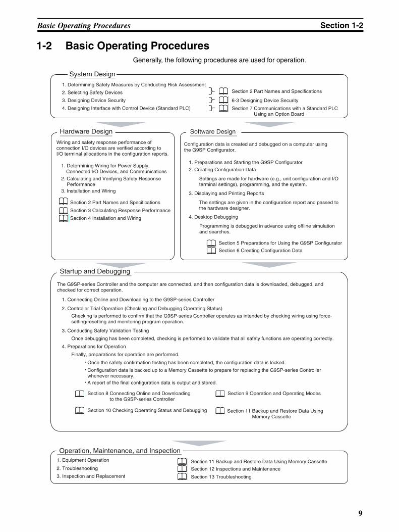
1-2 Basic Operating ProceduresGenerally, the following procedures are used for operation.
System Design
1. Determining Safety Measures by Conducting Risk Assessment
2. Selecting Safety Devices
3. Designing Device Security
4. Designing Interface with Control Device (Standard PLC)
Software DesignHardware Design
Section 2 Part Names and Specifications
Section 3 Calculating Response Performance
Section 4 Installation and Wiring
Wiring and safety response performance of connection I/O devices are verified according to I/O terminal allocations in the configuration reports.
Startup and Debugging
Operation, Maintenance, and Inspection
Section 2 Part Names and Specifications
6-3 Designing Device Security
Section 7 Communications with a Standard PLC Using an Option Board
1. Determining Wiring for Power Supply, Connected I/O Devices, and Communications
2. Calculating and Verifying Safety Response Performance
3. Installation and Wiring
Configuration data is created and debugged on a computer using the G9SP Configurator.
1. Preparations and Starting the G9SP Configurator
2. Creating Configuration Data
4. Desktop Debugging
Settings are made for hardware (e.g., unit configuration and I/O terminal settings), programming, and the system.
3. Displaying and Printing Reports
The settings are given in the configuration report and passed to the hardware designer.
Programming is debugged in advance using offline simulation and searches.
Section 5 Preparations for Using the G9SP Configurator
Section 6 Creating Configuration Data
The G9SP-series Controller and the computer are connected, and then configuration data is downloaded, debugged, and checked for correct operation.
1. Connecting Online and Downloading to the G9SP-series Controller
2. Controller Trial Operation (Checking and Debugging Operating Status)
4. Preparations for Operation
Checking is performed to confirm that the G9SP-series Controller operates as intended by checking wiring using force-setting/resetting and monitoring program operation.
3. Conducting Safety Validation Testing
Once debugging has been completed, checking is performed to validate that all safety functions are operating correctly.
Finally, preparations for operation are performed.
Configuration data is backed up to a Memory Cassette to prepare for replacing the G9SP-series Controller whenever necessary.
Once the safety confirmation testing has been completed, the configuration data is locked.
A report of the final configuration data is output and stored.
Section 10 Checking Operating Status and Debugging
Section 8 Connecting Online and Downloading to the G9SP-series Controller
Section 9 Operation and Operating Modes
Section 11 Backup and Restore Data Using Memory Cassette
Section 11 Backup and Restore Data Using Memory Cassette
Section 12 Inspections and Maintenance
Section 13 Troubleshooting
1. Equipment Operation
2. Troubleshooting
3. Inspection and Replacement
9

Basic Operating Procedures Section 1-2
10

Hardware Settings
SECTION 2Part Names and Specifications
This section provides the names of G9SP-series Controller parts, specifications, and terminal arrangements.
2-1 G9SP-series Controllers . . . . . . . . . . . . . . . . . . . . . . . . . . . . . . . . . . . . . . . . . 12
2-1-1 Part Names and Indicators . . . . . . . . . . . . . . . . . . . . . . . . . . . . . . . . 12
2-1-2 Terminal Arrangements . . . . . . . . . . . . . . . . . . . . . . . . . . . . . . . . . . 16
2-1-3 General Specifications . . . . . . . . . . . . . . . . . . . . . . . . . . . . . . . . . . . 17
2-1-4 I/O Specifications . . . . . . . . . . . . . . . . . . . . . . . . . . . . . . . . . . . . . . . 17
2-1-5 Safety Inputs . . . . . . . . . . . . . . . . . . . . . . . . . . . . . . . . . . . . . . . . . . . 20
2-1-6 Safety Outputs . . . . . . . . . . . . . . . . . . . . . . . . . . . . . . . . . . . . . . . . . 33
2-2 Expansion I/O Units . . . . . . . . . . . . . . . . . . . . . . . . . . . . . . . . . . . . . . . . . . . . 39
2-2-1 Part Names and Indicators . . . . . . . . . . . . . . . . . . . . . . . . . . . . . . . . 39
2-2-2 Terminal Arrangements . . . . . . . . . . . . . . . . . . . . . . . . . . . . . . . . . . 41
2-2-3 I/O Specifications . . . . . . . . . . . . . . . . . . . . . . . . . . . . . . . . . . . . . . . 44
2-2-4 Current Consumption . . . . . . . . . . . . . . . . . . . . . . . . . . . . . . . . . . . . 46
2-3 Option Units . . . . . . . . . . . . . . . . . . . . . . . . . . . . . . . . . . . . . . . . . . . . . . . . . . 47
2-3-1 RS-232C Option Board (CP1W-CIF01) . . . . . . . . . . . . . . . . . . . . . . 47
2-3-2 Ethernet Option Board (CP1W-CIF41) . . . . . . . . . . . . . . . . . . . . . . 48
2-3-3 Memory Cassette (CP1W-ME05M) . . . . . . . . . . . . . . . . . . . . . . . . . 49
11

G9SP-series Controllers Section 2-1
2-1 G9SP-series ControllersThis section provides the names of Controller parts, I/O specifications, andterminal arrangements. Refer to 4-1 Installation for dimensions and weightsand 4-2 Wiring for wiring diagrams.
2-1-1 Part Names and Indicators
Nomenclature and Functions
G9SP-N10S
G9SP-N10D
G9SP-N20S
(1) Operation Indicators
(5) Memory Cassette Slot
(2) USB Port
(3) Push Switch
(4) DIP Switch
(8) I/O Indicators
(9) Terminal Block
(8) I/O Indicators
(9) Terminal Block
(7) Expansion I/O Unit Connector
(6) Option Board Slot
(1) Operation Indicators
(5) Memory Cassette Slot
(2) USB Port
(3) Push Switch
(4) DIP Switch
(8) I/O Indicators (9) Terminal Block
(8) I/O Indicators(9) Terminal Block
(7) Expansion I/O Unit Connector
(6) Option Board Slot
12
G9SP-series Controllers Section 2-1
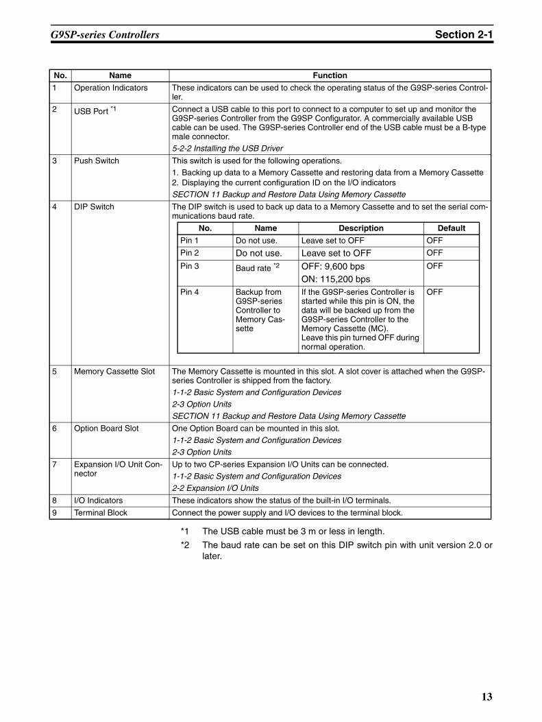
*1 The USB cable must be 3 m or less in length.
*2 The baud rate can be set on this DIP switch pin with unit version 2.0 orlater.
No. Name Function
1 Operation Indicators These indicators can be used to check the operating status of the G9SP-series Control-ler.
2 USB Port *1 Connect a USB cable to this port to connect to a computer to set up and monitor the G9SP-series Controller from the G9SP Configurator. A commercially available USB cable can be used. The G9SP-series Controller end of the USB cable must be a B-type male connector.
5-2-2 Installing the USB Driver
3 Push Switch This switch is used for the following operations. 1. Backing up data to a Memory Cassette and restoring data from a Memory Cassette2. Displaying the current configuration ID on the I/O indicatorsSECTION 11 Backup and Restore Data Using Memory Cassette
4 DIP Switch The DIP switch is used to back up data to a Memory Cassette and to set the serial com-munications baud rate.
No. Name Description Default
Pin 1 Do not use. Leave set to OFF OFF
Pin 2 Do not use. Leave set to OFF OFF
Pin 3 Baud rate *2 OFF: 9,600 bpsON: 115,200 bps
OFF
Pin 4 Backup from G9SP-series Controller to Memory Cas-sette
If the G9SP-series Controller is started while this pin is ON, the data will be backed up from the G9SP-series Controller to the Memory Cassette (MC).Leave this pin turned OFF during normal operation.
OFF
5 Memory Cassette Slot The Memory Cassette is mounted in this slot. A slot cover is attached when the G9SP-series Controller is shipped from the factory.
1-1-2 Basic System and Configuration Devices
2-3 Option UnitsSECTION 11 Backup and Restore Data Using Memory Cassette
6 Option Board Slot One Option Board can be mounted in this slot.
1-1-2 Basic System and Configuration Devices
2-3 Option Units
7 Expansion I/O Unit Con-nector
Up to two CP-series Expansion I/O Units can be connected.1-1-2 Basic System and Configuration Devices
2-2 Expansion I/O Units
8 I/O Indicators These indicators show the status of the built-in I/O terminals.
9 Terminal Block Connect the power supply and I/O devices to the terminal block.
13
G9SP-series Controllers Section 2-1
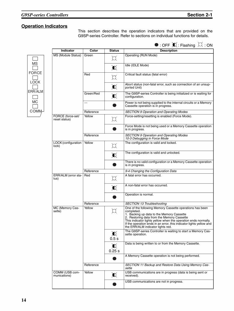
Operation IndicatorsThis section describes the operation indicators that are provided on theG9SP-series Controller. Refer to sections on individual functions for details.
: OFF : Flashing : ONIndicator Color Status Description
MS (Module Status) Green Operating (RUN Mode)
Idle (IDLE Mode)
Red Critical fault status (fatal error)
Abort status (non-fatal error, such as connection of an unsup-ported Unit)
Green/Red The G9SP-series Controller is being initialized or is waiting for configuration.
--- Power is not being supplied to the internal circuits or a Memory Cassette operation is in progress.
Reference SECTION 9 Operation and Operating ModesFORCE (force-set/reset status)
Yellow Force-setting/resetting is enabled (Force Mode).
Force Mode is not being used or a Memory Cassette operation is in progress.
Reference SECTION 9 Operation and Operating Modes10-3 Debugging in Force Mode
LOCK (configuration lock)
Yellow The configuration is valid and locked.
The configuration is valid and unlocked.
There is no valid configuration or a Memory Cassette operation is in progress.
Reference 9-4 Changing the Configuration DataERR/ALM (error sta-tus)
Red A fatal error has occurred.
A non-fatal error has occurred.
Operation is normal.
Reference SECTION 13 TroubleshootingMC (Memory Cas-sette)
Yellow One of the following Memory Cassette operations has been completed.1. Backing up data to the Memory Cassette2. Restoring data from the Memory CassetteThis indicator lights yellow when the operation ends normally.If the operation ends in an error, this indicator lights yellow and the ERR/ALM indicator lights red.
0.5 s
The G9SP-series Controller is waiting to start a Memory Cas-sette operation.
0.25 s
Data is being written to or from the Memory Cassette.
A Memory Cassette operation is not being performed.
Reference SECTION 11 Backup and Restore Data Using Memory Cas-sette
COMM (USB com-munications)
Yellow USB communications are in progress (data is being sent or received).
USB communications are not in progress.
MS
FORCE
ERR/ALM
MC
COMM
LOCK
14

G9SP-series Controllers Section 2-1
Precautions for Safe Use
If the MC indicator is flashing at 0.25-s intervals, it indicates that the MemoryCassette is being accessed (read or written).
Do not turn OFF the internal circuit power supply to the G9SP-series Control-ler or remove the Memory Cassette until the indicator stops flashing. If thepower supply is turned OFF while data is being accessed, data in the G9SP-series Controller may be corrupted or lost.
I/O IndicatorsThis section describes the I/O indicators that are provided on the G9SP-series Controller.
Self-diagnosis is performed to detect circuit failures and other circuit problemsfor Safety Input and Safety Output terminals. If errors are detected in this self-diagnosis, the terminal where the error occurred will be shown by a red indica-tor.
: OFF : Flashing : ON
!WARNING Serious injury may possibly occur due to loss of required safety functions. Donot use indicators on the G9SP-series Controller for safety operations.
Indicator name Color Status MeaningOUT PWR (Output Power) Green The output power supply is normal.
• The output power supply is not being supplied.• The Controller is being initialized.• Configuring Mode• A fatal error has occurred.
Si0 to Sin n: Terminal number of Safety Input terminal
Yellow The input signal is ON.
Red • An error was detected in an input circuit.• A discrepancy error (input data mismatch) was detected for Dual Chan-
nel Mode settings.• If an error is detected for a Memory Cassette operation, the terminal
number indicator that corresponds to the error code will light.An error was detected in other terminal in Dual Channel Mode (with no error for this input).
--- • The input signal is OFF.• Initialization is in progress.• Waiting for configuration.• A fatal error occurred.
So0 to Son n: Terminal number of Safety Output terminal
Yellow The output signal is ON.
Red • An error was detected in an output circuit.• A dual channel violation (output data mismatch) was detected in Dual
Channel Mode.An error was detected in other terminal in Dual Channel Mode (with no error for this input).
--- The output signal is OFF.
O0 to On n: Terminal number of Stan-dard Output terminal
Yellow The output signal is ON.
The output signal is OFF.
15

G9SP-series Controllers Section 2-1
2-1-2 Terminal ArrangementsG9SP-N10S
G9SP-N10D
G9SP-N20S
Internal Circuits and Wiring Diagram
Terminals
NC
NC NC
Si0Si1
O0
Si2Si3
Si4Si5
Si6Si7
Si8Si9
V2
V1 G1
So1So2
So3
T0T1 T3Top
(17 pins)
Bottom (14 pins) G2
So0NC
NCO1
O2O3
T2
NC NCSi0
So8
Si1
So9
Si2
So10
Si3
So11
Si4
So12
Si5
So13
Si6
So14
Si7
So15
Si8Si9
V2
V1 G1
So1So2
So3
NCNC
T0
So7So4
So5So6
T1Top (24 pins)
Bottom (19 pins) G2
So0NC
NCNC
T2T3
T4T5
NC
NC
NCSi0Si1
Si2Si3
Si4Si5
Si6Si7
Si8Si9
Si10Si11
Si12Si13
Si14Si15
Si16Si17
Si18
V2
V1 G1
T0T1
T2
Si19Top (24 pins)
Bottom (19 pins)
So0G2 So1
So2So3
So4So5
So6So7
NCNC T3
T4T5
D+D−
USB
Internal Circuit
24 VDCV1
G1
Si0
Si19
T0
T5
V2
G2
So0
So7
O0
O3
L
L
L
L
Safety Input Circuit
Test Output Circuit
Safety Output Circuit
Standard Output Circuit
Terminals Function
V1/G1 Power supply terminals for internal and input circuits (24 VDC).
V2/G2 Power supply terminals for output circuits (24 VDC).
NC Not used (Do not connect)
Si0 to Si19 Safety Input terminals
T0 to T5 Test Output terminals
So0 to So15 Safety Output terminals
O0 to O3 Standard Output terminals
16

G9SP-series Controllers Section 2-1
2-1-3 General Specifications
*1 The current consumption of external devices is not included.
2-1-4 I/O SpecificationsI/O Capacities
Safety Input Specifications
Precautions for Correct Use
Safety devices with semiconductor outputs, such as safety light curtains,sometimes provide a pulse output that is used to detect wiring errors.Observe the following when connecting a safety device with a semiconductoroutput to a Safety Input terminal on the G9SP-series Controller.
• OFF pulse width when semiconductor output is ON: 700 µs max.
Item Specification
Power supply voltage (V1, V2) 24 VDC (20.4 to 26.4 VDC −15%+10%)
Current consumption*1 400 mA (V1: 300 mA, V2: 100 mA) (N10S)500 mA (V1: 300 mA, V2: 200 mA) (N10D)500 mA (V1: 400 mA, V2: 100 mA) (N20S)
Insulation class Class III (SELV)
Overvoltage category II
Noise immunity Compliant with IEC 61131-2
Vibration resistance 5 to 8.4 Hz: 3.5 mm, 8.4 to 150 Hz: 9.8 m/s2
Shock resistance 147 m/s2: 11ms
Mounting DIN Track (IEC 60715 TH35-7.5 / TH35-15) or M4 screws
Ambient operating temperature 0 to 55°CAmbient operating humidity 10% to 90% (with no condensation)
Ambient storage temperature −20 to 75°CAtmosphere No corrosive gas
Operating altitude 2,000 m max.
Pollution degree Pollution degree 2
Degree of protection IP20 except terminal blocks
Terminal screws M3 self-rising screws
Item G9SP-N10S G9SP-N10D G9SP-N20S
Safety Inputs 10 points 10 points 20 points
Safety Outputs 4 points 16 points 8 points
Test Outputs 4 points 6 points 6 points
Standard Outputs 4 points - -
Item Specification
Input type Sinking inputs (PNP compatible)
Input current 6 mA
ON voltage 11 VDC min. (between inputs and G1)
OFF voltage 5 VDC max. (between inputs and G1)
OFF current 1 mA max.
17

G9SP-series Controllers Section 2-1
• ON pulse width when semiconductor output is OFF: 30 µs max.
Test Output Specifications
*1 Connection to an OMRON D40A or D40Z Non-Contact Switch is possi-ble.
*2 With the Muting Lamp Output (open circuit detection)
Safety Output Specifications
*1 Total current for So0 to So3 and So4 to So7.
*2 Total current for So0 to So3, So4 to So7, So8 to So11, and So12 to So15.
Precautions for Safe Use
When a Safety Output is set as a pulse output, make sure that the connecteddevice does not malfunction for the OFF pulse (pulse width: 640 µs).
700 µs max.
30 µs max.
Item Specification
Output type Sourcing outputs (PNP)
Rated output current G9SP-N10S T0, T1: 60 mA max.T2: 30 mA max.*1
T3: 300 mA max.*2
T0-2 total: 60mA max.
G9SP-N10D T0, T1, T2: 60 mA max.T3: 300 mA max.*2
T4, T5: 30 mA max.*1
T0-2, T4-5 total: 60mA max.
G9SP-N20S T0, T1, T2: 100 mA max.T3: 300 mA max.*2
T4, T5: 30 mA max.*1
T0-2, T4-5 total: 120 mA max.
ON residual voltage 1.8 V max. (between test outputs and V1)
Leakage current 0.1 mA max.
Item Specification
Output type Sourcing outputs (PNP)
Rated output current 0.8 A max./point1.6 A max./4 points (N10S or N20S)*1
1.2 A max./4 points (N10D)*2
ON residual voltage 1.2 V max. (between outputs and V2)
OFF residual voltage 2 V max.
Leakage current 0.1 mA max.
18

G9SP-series Controllers Section 2-1
Standard Output Specifications of G9SP-N10S
Input Wiring
Devices with Contact OutputsA devices with a contact output, such as an emergency stop pushbutton orsafety limit switch, is input to the G9SP-series Controller using a Safety Inputterminal (Si) and Test Output terminal (To).
The total length of cable connected to one Test Output must be 600 m or less.
Devices with PNP Semiconductor Outputs (Current-sourcing Outputs)The signal from a device with a PNP semiconductor output, such as a lightcurtain, is input to a Safety Input terminal (Si). Check the specifications of theconnected device for the maximum cable length.
Item Specification
Output type Sourcing outputs (PNP)
ON residual voltage 1.5 V max. (between outputs and V2)
Rated output current 100mA max.
To
Si
G9SP V1
G1
24 VDC
6 mA typ
To0
Si0
G9SP
Si1
L1
L2
L3
L4
L1+L2+L3+L4 600m
Si
G9SP
V1
G1
24 VDC
6 mA typ
Device with PNP semiconductor output
19

G9SP-series Controllers Section 2-1
Output Wiring• Refer to the following information when connecting output devices.
• The cable length from an output terminal to the output device must be 100m or less.
2-1-5 Safety InputsThis section describes the Safety Input functions of the G9SP-series Control-ler’s Safety I/O functions. The G9SP-series Controller diagnoses the externaldevices connected to Safety Input terminals.
Connectable External DevicesThe following table lists the connectable external devices (Safety Devices andStandard Devices).
The following OMRON Safety Devices can be connected directly without spe-cial controllers.
So
G9SP
V2
G2
24 VDC
0.8 A max.
L
Type Examples
Safety Devices with mechanical contacts
Emergency stop switches, safety limit switches, safety switches, enable switches, and 2-hand switches
Safety Devices with semi-conductor outputs
Safety curtains and laser scanners
Standard Devices Limit switches and muting sensors
Type Model and category/PL
OMRON Single Beam Safety Sensor
E3ZS and E3FS (Conforms to Safety Category 2 and PLc.)
OMRON Non-contact Switch
D40A (Conforms to Safety Category 3 and PLd.)D40Z (Conforms to Safety Category 4 and PLe.)
OMRON Safety Mat UM (Conforms to Safety Category 3 and PLd.)
20

G9SP-series Controllers Section 2-1
Setting Safety Input TerminalsA Safety Input terminal on the G9SP-series Controller can be easily set byselecting the connected external device on the G9SP Configurator. (Fordetails, refer to 6-2-2 Hardware Settings.)
External Device Connection Examples
Connecting Safety Devices with Mechanical ContactsConnecting an emergency stop switch is described here as an example ofconnecting Safety Devices with mechanical outputs.
Wiring Example
If redundant emergency stop switches are used, a Test Output terminal is alsoused.
G9SP Configurator Setting Example
The selected connection devices are displayed.I/O comments are treated as names and can be used in the program.
The settings are displayed.
These are the Test Output terminals that are used together with the Safety Input terminals.
You drag and drop connected devices to the terminals to which there are connected. This completes the settings for Safety Input terminals.
Si0
T0 T1
Si1
2212
11 21
Si0
T0
Si1
12 22
11 21
Circuit for Detecting Short Circuits between Input Signals
Circuit for Which Detecting Short Circuits between Input Signals Is Not Necessary
21
G9SP-series Controllers Section 2-1
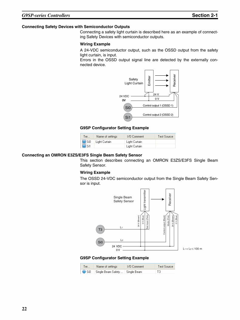
Connecting Safety Devices with Semiconductor OutputsConnecting a safety light curtain is described here as an example of connect-ing Safety Devices with semiconductor outputs.
Wiring Example
A 24-VDC semiconductor output, such as the OSSD output from the safetylight curtain, is input.Errors in the OSSD output signal line are detected by the externally con-nected device.
G9SP Configurator Setting Example
Connecting an OMRON E3ZS/E3FS Single Beam Safety SensorThis section describes connecting an OMRON E3ZS/E3FS Single BeamSafety Sensor.
Wiring Example
The OSSD 24-VDC semiconductor output from the Single Beam Safety Sen-sor is input.
G9SP Configurator Setting Example
Si0
Si1
Safety Light Curtain
Control output 1 (OSSD 1)
24 VDC0V
24 V
0V 0 V
Em
itter
Rec
eive
r
Control output 2 (OSSD 2)
24 VDC0 V
T3
Si0
Ligh
t tra
nsm
itter
Single BeamSafety Sensor
Rec
eive
r
24 V
(B
row
n)
0 V
(B
lue)
Test
inpu
t (P
ink)
Con
trol
out
put (
Bla
ck)
24 V
(B
row
n)
0 V
(B
lue)
Mod
e (P
ink)
L1 + L2 ≤ 100 m
L1
L2
22

G9SP-series Controllers Section 2-1
Precautions for Correct Use
• Only one E3ZS/E3FS Single Beam Safety Sensor can be connected to aG9SP-series Safety Controller with unit version 1.0 or unit version 1.1.The maximum number of E3ZS/E3FS Single Beam Safety Sensors that canbe connected to a G9SP-series Safety Controller with unit version 2.0 orlater is as follows:G9SP-N10S: 4 (1 Sensor × 4 systems)G9SP-N10D/20S: 6 (1 Sensor × 6 systems)
• The total wiring length (L1 + L2 in the above figure) for the E3ZS/E3FS Sin-gle Beam Safety Sensor must be 100 m or less.
• The E3ZS/E3FS Single Beam Safety Sensor can be used in a Safety Cate-gory 2 or lower, or PLc or lower application. It cannot be used in a SafetyCategory 3 or higher, or PLd or higher application.
• If you use more than one Single Beam Safety Sensor, it may not be possi-ble to detect short circuits between wires. To satisfy safety category 2, youmust protect the cables to the Single Beam Safety Sensors from externaldamage. Use ducts, separate the cables for each system, or implementother measures to protect the cables from external damage when you con-nect the Single Beam Safety Sensors. You can also provide protectionagainst short circuits by using special cables (XS2F).
• The test period for a Single Beam Safety Sensor test is as given below. Usethe value as reference to determine conformance with standards for yoursystem.G9SP-N10S: 112 × Cycle time (ms)G9SP-N10D/20S: 168 × Cycle time (ms)
23

G9SP-series Controllers Section 2-1
Connecting an OMRON D40A or D40Z Non-contact SwitchThis section describes connecting an OMRON D40A or D40Z Non-contactSwitch.
Wiring Example
The non-contact switch output (black line) from the OMRON D40A or D40ZNon-contact Switch is input to a Safety Input terminal. This is a one-line sig-nal. When connecting it to the G9SP-series Controller, branch it, as shown forSi0 and Si1 in the following diagram.
Only one Test Output terminal is used. Connect the Non-Contact Switch input(white line). The inputs for up to 15 Non-Contact Switches can be connectedin series to one Test Output terminal.
G9SP Configurator Setting Example
T4
0 V
24 VDC
Si0
L1
L1+L2+ +Ln+1+Ln+2 ≤ 100m
L2
n Switches (15 max.)
Ln+1
Ln+2
Si1
White Black Brown Blue White Black Brown Blue White Black Brown Blue
24

G9SP-series Controllers Section 2-1
Precautions for Correct Use
• The maximum number of Switches that can be connected to a G9SP-seriesController is given below. G9SP-N10S: 15 (15 × 1 system)G9SP-N10D/20S: 30 (15 × 2 system)
• The following Test Output terminals must be used to connect to the D40A orD40Z Non-contact Switch. Do not connect any other Test Output terminals.G9SP-N10S: T2G9SP-N10D/20S: T4 and T5
• The total wiring length (L1 + L2 +…+ Ln+2 in the above figure) for the D40A/D40Z Non-contact Switch must be 100 m or less.
• The D40A Non-contact Switch can be used in a Safety Category 3 or lower,or a PLd or lower application. It cannot be used in an Safety Category 4 orPLe application.
• The D40Z Non-contact Switch can be used in a Safety Category 4 or lower,or a PLe or lower application.
Additional Information
If you use a standard model of the D40A/D40Z (with a cable) or if you usebranch connections with the XS2F/XS2W, multiple the cable lengths by twowhen you calculate the total wiring length.
Connecting an OMRON UM Safety MatThis section describes connecting an OMRON UM Safety Mat.
Wiring Example
A Safety Output from the UM Safety Mat is connected to a Safety Input termi-nal. Up to 12 UM Safety Mat can be connected in series to one Test Outputterminal.
Blue White
Blue
Black
White
Brown
Black Brown
T3T2
Si0 Si1
Safety Mat 1
Safety Mat 2
This wiring example if for connecting two UM Safety Mats.
L1
L2
L3In this example, L1 + L2 + L3 ≤ 100 m.
25
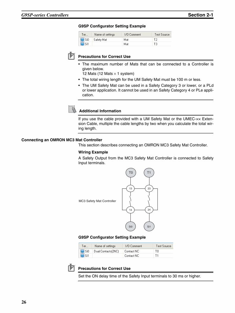
G9SP-series Controllers Section 2-1
G9SP Configurator Setting Example
Precautions for Correct Use
• The maximum number of Mats that can be connected to a Controller isgiven below.12 Mats (12 Mats × 1 system)
• The total wiring length for the UM Safety Mat must be 100 m or less.
• The UM Safety Mat can be used in a Safety Category 3 or lower, or a PLdor lower application. It cannot be used in an Safety Category 4 or PLe appli-cation.
Additional Information
If you use the cable provided with a UM Safety Mat or the UMEC-×× Exten-sion Cable, multiple the cable lengths by two when you calculate the total wir-ing length.
Connecting an OMRON MC3 Mat ControllerThis section describes connecting an OMRON MC3 Safety Mat Controller.
Wiring Example
A Safety Output from the MC3 Safety Mat Controller is connected to SafetyInput terminals.
G9SP Configurator Setting Example
Precautions for Correct Use
Set the ON delay time of the Safety Input terminals to 30 ms or higher.
T0 T1
Si0 Si1
24
2313
14
MC3 Safety Mat Controller
26

G9SP-series Controllers Section 2-1
Functions of Safety Input TerminalsThis section describes the functions of the Safety Input terminals on theG9SP-series Controller. The following functions are allocated automaticallywhen the external devices to connect are selected from the G9SP Configura-tor.
Self-diagnosis
There is no redundancy.
Safety Input functions
The values that are read from the Safety Input terminals are passed to the program only after evaluating them for the Safety Input functions.
Safety Input terminals
Safety Input terminals
Safety Output functions
Safety Output terminals
Test pulse evaluation
No diagnosis
Device with mechanical contacts
Single Beam Safety Sensor
Non-contact Switch
Safety Mat
A pulse is output at a specific interval to detect failure of or wiring errors in the externally connected device. The test mode that is used depends on the Safety Device.
Dual channel evaluation Single channel
Dual channel equivalent
Two inputs are checked to make sure they have the same value.
Dual channel complementary
Two inputs are checked to make sure they have different values.
Safety Mat
A two-input logic check is made for a Safety Mat.
Other Functions
When Safety Input terminals are used as dual channels, the two inputs are checked for consistency.
Input filters
ON delay
OFF delay
ON delays and OFF delays can be set to prevent malfunctions caused by noise or by chattering of externally connected devices.
Error notification Checking with I/O indicators
Yellow indicators show the input is ON and normal. Red indicators show errors.Self-diagnosis of Safety Input terminals provides notification of the locations and causes of errors. The G9SP Configurator can be used to check error causes (e.g., failure of externally
connected devices and wiring errors, such as short-circuits or ground faults).
The same information that is available on the G9SP Configurator can be sent to a Standard PLC that is connected through an Option Board.
Checking with Option Board Communications
Checking with the G9SP Configurator
27

G9SP-series Controllers Section 2-1
Test Pulse EvaluationA test pulse with a specific period is output on the 24-V power line from a TestOutput terminal to detect wiring errors and failure of the externally connecteddevice. The following parameters are also used.
• Diagnosis
• Test source
• Test Mode
DiagnosisDiagnosis is set according to the type of external device that is connected tothe Safety Input terminal.
Test SourceThis parameter determines the Test Output terminal to use when the Diagno-sis Parameter is set to Diagnosis. The Test Output terminal is automaticallyassigned by the G9SP Configurator, but it can be changed to any Test Outputterminal.
Precautions for Correct Use
The following Test Output terminals must be used to connect to the D40A orD40Z Non-contact Switch. Do not connect any other Test Output terminals.
G9SP-N10S: T2G9SP-N10D/20S: T4 and T5
Combining Si0 and T0
External contacts
For example, it is possible to detect a short-circuit with the positive side of the power supply for the input signal.
The test pulse is output on the 24-V power line from Test Output terminal T0 and the Controller monitors Safety Input terminal Si0 to see if the test pulse is returned normally.
V1
G1
T0
Si0
G9SP
24V0V
Setting Description
No diagnosis A test pulse from the Test Output terminal is not output for diagno-sis. This setting is used for Safety Devices with semiconductor out-puts, such a Safety Light Curtain, and for Standard Devices.
Diagnosis A test pulse from the Test Output terminal is output for diagnosis.The mode of the Test Output to use as the test source is selected according to the Safety Device that is connected.
28

G9SP-series Controllers Section 2-1
Test ModeWhen the Diagnosis parameter is set to Diagnosis, the following setting isrequired to output a test pulse that is suitable for the external device.
Dual Channel EvaluationInput safety terminals can be used as dual channels (one pair) for the G9SP-series Controller. This function evaluates the data for two inputs to check fordiscrepancy. The following parameters are also used.
• Single/Dual Setting
• Discrepancy Time
Single/Dual Setting
Discrepancy TimeFor two inputs set in a Dual Channel Mode, the time is monitored from achange in the value of one input to a change in the value of the other input. Anerror occurs if the value of the other input does not change within the set dis-crepancy time.The discrepancy time can be set in increments of 10 ms between 0 (disabled)and 65,530 ms.The discrepancy time cannot be set in Single Channel Mode.
Relationship between Input TagsThe data that is input to Safety Input terminals is evaluated as shown in thefollowing table. The results of this evaluation are reflected in the input tagsthat are used in the program.
Setting Function
Mechanical con-tacts
The test pulse is connected to a device with mechanical contacts. The Safety Input terminal’s Test Output signal (pulse output) is input through the mechanical contact device.The following can be detected: Contact of the input signal line with the positive side of the power supply line, ground faults, and short-circuits to the other input signal lines.
Single Beam Safety Sensor
An OMRON E3ZS/E3FS Single Beam Safety Sensor is connected. A test signal for Single Beam Safety Sensor diagnosis is output.
Non-contact Switch
An OMRON D40A or D40Z Non-contact Switch is connected. Test signals for the D40A or D40Z will be output.
Safety Mat An OMRON UM Safety Mat is connected. Test signals for diagnos-ing the Safety Mat will be output.
Setting Description
Single Channel The Safety Input terminals are used as independent Safety Input terminals.
Dual Channel Equivalent
The Safety Input terminals are used as a dual channel equivalent pair.
Dual Channel Complementary
The Safety Input terminals are used as a dual channel comple-mentary pair.
Safety Mat The Safety Input terminals are used as Safety Mat Safety Input pair.
Single/dual Input signal from Safety Input
terminal
Value after evaluation
Meaning of status
Si (n) Si (n+1)
Single Channel 0 0 Inactive (OFF)
1 1 Active (ON)
29

G9SP-series Controllers Section 2-1
n = Even number
Operation for Dual Channel Equivalent Inputs: Normal Operation
Operation for Dual Channel Equivalent Inputs: Discrepancy Error
Single/dual Input signal from Safety Input
terminal
Value after evaluation
Meaning of status
Si (n) Si (n+1) Si (n) Si (n+1)
Dual Channel Equivalent
0 0 0 0 Inactive (OFF)
0 1 0 0 Discrepant status
1 0 0 0 Discrepant status
1 1 1 1 Active (ON)
Dual Channel Complementary
0 0 0 1 Discrepant status
0 1 0 1 Inactive (OFF)
1 0 1 0 Active (ON)
1 1 0 1 Discrepant status
Single/dual Status of Safety Mat
Value after evaluation Meaning of status
Si (n) Si (n+1)
Safety Mat No load 1 1 Active (ON)
With load 0 0 Inactive (OFF)
Si0 terminal
Si1 terminal
Discrepancy Time
I/O tag Si0
I/O tag Si1
Discrepancy Time
Si0 terminal
Si1 terminal
I/O tag Si0
I/O tag Si1
Discrepancy TimeDiscrepancy Time
30

G9SP-series Controllers Section 2-1
Input FiltersON delays and OFF delays can be set to prevent malfunctions caused bynoise or by chattering of externally connected devices.ON delays and OFF delays can be set for each terminal from 0 to 1,000 ms.The effect of chattering from external devices can be reduced more byincreasing the delay time, but this will slow the response to input signals.
Precautions for Correct Use
• The ON and OFF delays can be set only as multiples of the cycle time ofthe G9SP-series Controller. If the cycle time changes, e.g., when the pro-gram is changed, the ON and OFF delay times will also change.
Example: Delays for a cycle time of 5 ms: ON delay of 10 × 5 ms = 50 msand OFF delay of 5 × 5 = 25 msDelays after changing cycle time to 6 ms: ON delay of 10 × 6 ms= 60 ms and OFF delay of 5 × 6 = 30 ms
• The OFF delay time will affect the safety response performance. Add it tothe reaction time. (Refer to 3-2 Reaction Times.)
Error NotificationSelf-diagnosis of Safety Input terminals provides notification of the locationsand causes of errors.The following three methods can be used to check if errors have beendetected.
• Checking with the I/O indicators on the Front of the G9SP-series Control-ler
The G9SP-series Controller will light or flash the I/O indicators on the frontpanel if an error is detected in the Safety Input terminals. This lets youidentify the terminal where the error was detected. Refer to 2-1-1 PartNames and Indicators for information on the indicator patterns.
• Checking with the G9SP Configurator
If the G9SP Configurator is connected online when an error has been de-tected in the Safety Input terminals, the terminal where the error was de-tected and the cause of the error can be checked. Refer to 10-1 MonitoringDevices for the procedures and displays for using the G9SP Configurator.
• Checking with Option Board Communications
Option Board communications can be used when an error has been de-tected in the Safety Input terminals to monitor the error location and errorcause from a Standard PLC. Refer to SECTION 7 Communications with aStandard PLC Using an Option Board for detailed specifications on com-munications procedures and data for Option Boards.
T: ON delay T: OFF delay
Limit switch or other input
I/O tag
31

G9SP-series Controllers Section 2-1
Operation at Error DetectionWhen the G9SP-series Controller detects an error in the Safety Input termi-nals, the following operations will take place.
• The Safety Input evaluation data that is passed to the program is madeinactive.
• The ERR indicator will flash red and the I/O indicator of the Safety Inputterminal where the error was detected will light red.If Dual Channel Mode is being used, the I/O indicator for the other termi-nal will flash red.
• The error will be recorded in the error log.
• Operation will continue.
Resetting ErrorsAll the following conditions must be met to reset errors that occur in the SafetyInputs.
• The cause of the error must be removed.
• An inactive signal must be input (e.g., pressing the emergency stop but-ton or opening a door).
32

G9SP-series Controllers Section 2-1
2-1-6 Safety OutputsThis section describes the Safety Output functions of the G9SP-series Con-trollers Safety I/O functions. The G9SP-series Controller diagnoses the exter-nal devices connected to Safety Output terminals.
Devices That Can Be ConnectedThe following table lists the devices that can be connected.
Setting Safety Output TerminalsA Safety Output terminal on the G9SP-series Controller can be easily set byselecting the connected external device on the G9SP Configurator. (Fordetails, refer to 6-2-2 Hardware Settings.)
Type Example
Safety Devices with PNP output contacts Safety relays and contactors
The selected connection devices are displayed. I/O comments are treated as names and can be used in the program.
The settings are displayed.
You drag and drop connected devices to the terminals to which they are to be connected. This completes the settings for Safety Output terminals.
33

G9SP-series Controllers Section 2-1
External Device Connection ExamplesRefer to the following information when connecting output devices.
!WARNING Serious injury may possibly occur due to breakdown of safety outputs or testoutputs. Do not connect loads beyond the rated values to the safety outputsand test outputs.
!WARNING Serious injury may possibly occur due to loss of required safety functions.Wire the G9SP-series Controller properly so that the 24VDC line does NOTtouch the outputs accidentally or unintentionally.
!WARNING Serious injury may possibly occur due to loss of required safety functions.Ground the 0V line of the power supply for external output devices so that thedevices do NOT turn ON when the safety output line or the test output line isgrounded.
!WARNING Serious injury may possibly occur due to loss of required safety functions. Useappropriate components or devices according to the requirements given in thefollowing table.
Precautions for Correct Use
• Be sure to separate I/O cables from high-voltage and power lines.
• The cable length from an output terminal to the output device must be100 m or less.
So0 to So15
G2
V2
24 VDC
L
G9SP-series Controller
0.8 A max.
Control device Requirements
Contactor Use a contactor with a forcibly guided mechanism. For feed-back signals to detect contactor failure, use a device with NC contacts. For feedback, use a device with NC contacts capa-ble of switching micro-loads of 6 mA at 24 VDC.
Other control device Verify whether the device is appropriate for the required safety category.
34

G9SP-series Controllers Section 2-1
Functions of Safety Output TerminalsThis section describes the functions of the Safety Output terminals on theG9SP-series Controller. The following functions are allocated automaticallywhen the external devices to connect are selected from the G9SP Configura-tor.
Test Pulse EvaluationA test pulse with a specific period is output on the 24-V power line from aSafety Output Terminal to detect wiring errors. This function is achieved withthe following parameter.
• Diagnosis
The results of program execution are evaluated by the Safety Output functions and the evaluation results are output from the Safety Output terminals.
Safety Input terminals
Safety Input functions
Program execution
Safety Output functions
Safety Output terminals
Self-diagnosis
There is no redundancy.
Test pulse evaluation
No diagnosis
Diagnosis
A pulse is output at a specific interval to detect wiring errors in the externally connected device.
Dual channel evaluation Single channel
Dual channel equivalent
Two outputs are checked to make sure they have the same value.
When Safety Output terminals are used as dual channels, the two outputs are checked for consistency.
Other Functions
Error notification
Self-diagnosis of Safety Output terminals provides notification of the locations and causes of errors.
Checking with I/O indicators
Yellow indicators show the output is ON and normal. Red indicators show errors.
The G9SP Configurator can be used to check error causes (e.g., failure of externally connected devices and wiring errors, such as short-circuits or ground faults).
The same information that is available on the G9SP Configurator can be sent to a Standard PLC that is connected through an Option Board.
Checking with Option Board Communications
Checking with the G9SP Configurator
35

G9SP-series Controllers Section 2-1
DiagnosisThe parameter determines whether test pulse evaluation is used. The errorsthat can be detected are determined by the setting of this parameter.
Precautions for Correct Use
• Disconnections can be detected by using the EDM function block.
• It the parameter is set to Diagnosis, OFF pulse signals with a pulse width of640 µs will be output when the Safety Output is ON to diagnose the outputcircuit. Check the input response time of the connected control device tomake sure it will not malfunction due to these OFF pulses.
Dual Channel Mode SettingThe G9SP-series Controller can use Safety Outputs in a Dual Channel Mode.
The following actions will be performed if a Dual Channel Mode is set:
• An error will occur if the two outputs from the user program are not equiv-alent.
• If an error is detected in either of the two output terminals, the outputs tothe external devices are both turned OFF.
This function is achieved with the following parameter.
• Single/Dual Setting
Single/Dual Setting
Channel mode
Description of operation
Fault Mode
Contact with positive side of power line
Ground faults Short circuits in output wiring
Output ON Output OFF
Output ON Output OFF
Short circuit
when both outputs are ON
Short circuit
when both outputs are OFF
Short circuit
when one output is
ON and the other is
OFF
No Diag-nosis
Test pulses are not output when the out-put is ON.
Not detect-able
Detectable Detectable Not detect-able
Not detect-able
Not detect-able
Detectable
Diagnosis Test pulses are output when the out-put is ON.
Detectable Detectable Detectable Not detect-able
Detectable Not detect-able
Detectable
Setting Description
Single channel The Safety Output terminals are used as independent Safety Input terminals.
Dual channel equiva-lent
The pair of Safety Output terminals are used as Dual Channel outputs. The outputs will turn ON if the paired Safety Outputs are both normal.
36
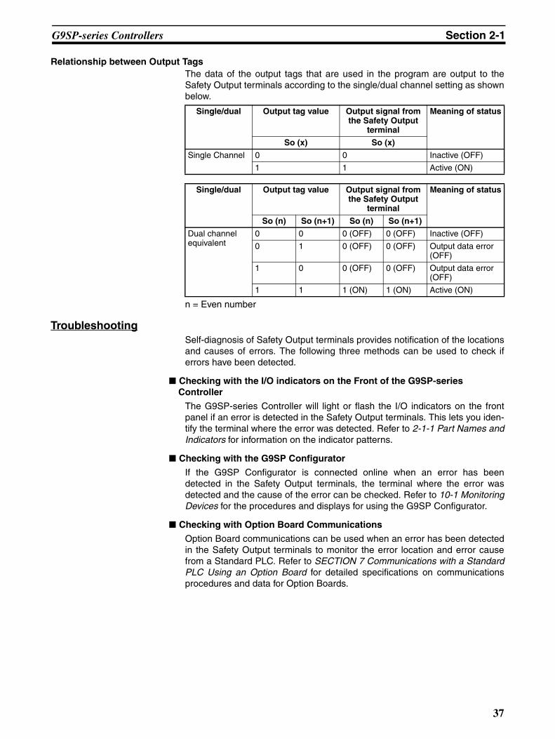
G9SP-series Controllers Section 2-1
Relationship between Output TagsThe data of the output tags that are used in the program are output to theSafety Output terminals according to the single/dual channel setting as shownbelow.
n = Even number
TroubleshootingSelf-diagnosis of Safety Output terminals provides notification of the locationsand causes of errors. The following three methods can be used to check iferrors have been detected.
Checking with the I/O indicators on the Front of the G9SP-series Controller
The G9SP-series Controller will light or flash the I/O indicators on the frontpanel if an error is detected in the Safety Output terminals. This lets you iden-tify the terminal where the error was detected. Refer to 2-1-1 Part Names andIndicators for information on the indicator patterns.
Checking with the G9SP Configurator
If the G9SP Configurator is connected online when an error has beendetected in the Safety Output terminals, the terminal where the error wasdetected and the cause of the error can be checked. Refer to 10-1 MonitoringDevices for the procedures and displays for using the G9SP Configurator.
Checking with Option Board Communications
Option Board communications can be used when an error has been detectedin the Safety Output terminals to monitor the error location and error causefrom a Standard PLC. Refer to SECTION 7 Communications with a StandardPLC Using an Option Board for detailed specifications on communicationsprocedures and data for Option Boards.
Single/dual Output tag value Output signal from the Safety Output
terminal
Meaning of status
So (x) So (x)
Single Channel 0 0 Inactive (OFF)
1 1 Active (ON)
Single/dual Output tag value Output signal from the Safety Output
terminal
Meaning of status
So (n) So (n+1) So (n) So (n+1)
Dual channel equivalent
0 0 0 (OFF) 0 (OFF) Inactive (OFF)
0 1 0 (OFF) 0 (OFF) Output data error (OFF)
1 0 0 (OFF) 0 (OFF) Output data error (OFF)
1 1 1 (ON) 1 (ON) Active (ON)
37
G9SP-series Controllers Section 2-1
Operation at Error DetectionThe G9SP-series Controller performs the following actions if an error isdetected in the Safety Output terminals:
• The outputs to external devices are immediately made inactive regardlessof the status of the user program.
• The ERR indicator will flash red and the I/O indicator of the Safety Outputterminal where the error was detected will light red. In Dual ChannelMode, indicator of the other output flashes red.
• The error is recorded in the error log.
• Operation continues.
Resetting ErrorsAll the following conditions must be met to reset errors that occur in the SafetyOutputs.
• The cause of the error must be removed.
• The output signal from the user application for the corresponding SafetyOutput terminal to the output tag must be made inactive.
38

Expansion I/O Units Section 2-2
2-2 Expansion I/O UnitsThis section provides the names of Expansion I/O Unit parts, I/O specifica-tions, and terminal arrangements. Refer to 4-1 Installation and 4-2 Wiring fordimensions and weights.
2-2-1 Part Names and Indicators
Part Names and Functions
Standard I/O Units with 20 I/O Points (CP1W-20EDT/20EDT1)
Standard Output Units with 32 I/O Points (CP1W-32ET/ET1)
1. Input terminals
4. Input indicators
3. Output terminals
6. Output indicators
5. Expansion connector
2. Expansion I/O connecting cable
20EDT1
Number Name Function
1 Input terminals Used to connect input devices.
2 Expansion I/O connecting cable
This cable is used to connect the adjacent Units, including the G9SP-series Controller, Expansion I/O Units, or Expansion Units. For extended connections or vertical arrangements, use the CP1W-CN811 I/O Connecting Cable (length: 800 mm).
3 Output terminals Used to connect output devices.
4 Input indicators Input status is displayed. An indicator will be ON when the input is ON.
5 Expansion con-nector
CP-series Expansion I/O Units can be connected.1-1-2 Basic System and Configuration Devices
2-2 Expansion I/O Units
6 Output indicators Output status is displayed. An indicator will be ON when the output is ON.
3. Output terminals
5. Expansion connector
2. Expansion I/O connecting cable
3. Output terminals
6. Output indicators
32ET
39

Expansion I/O Units Section 2-2
I/O Indicators
: OFF : ON
!WARNING Serious injury may possibly occur due to loss of required safety functions. Donot use the G9SP-series Controller's indicators for safety operations.
Indicator Color Status Description
IN0 to INnn: Terminal number(Standard Input terminals)
Yellow The input signal is ON.
--- The input signal is OFF.
OUT0 to OUTnn: Terminal number(Standard Output terminals)
Yellow The output signal is ON.
The output signal is OFF.
40
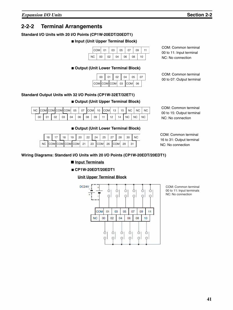
Expansion I/O Units Section 2-2
2-2-2 Terminal ArrangementsStandard I/O Units with 20 I/O Points (CP1W-20EDT/20EDT1)
Input (Unit Upper Terminal Block)
Output (Unit Lower Terminal Block)
Standard Output Units with 32 I/O Points (CP1W-32ET/32ET1)
Output (Unit Upper Terminal Block)
Output (Unit Lower Terminal Block)
Wiring Diagrams: Standard I/O Units with 20 I/O Points (CP1W-20EDT/20EDT1)
Input Terminals
CP1W-20EDT/20EDT1
Unit Upper Terminal Block
COM: Common terminal
00 to 11: Input terminalNC: No connection
COM: Common terminal00 to 07: Output terminal
COM: Common terminal00 to 15: Output terminal
NC: No connection
COM: Common terminal
16 to 31: Output terminal
NC: No connection
COM 01 03 05 07 09 11
NC 00 02 04 06 08 10
00 01 02 04 05 07
COM COM COM 03 COM 06
NC COM COM COM COM 05 07 COM 10 COM 13 15 NC NC NC
00 01 02 03 04 06 08 09 11 12 14 NC NC NC
16 17 18 19 20 22 24 25 27 28 30 NC
NC COM COM COM COM 21 23 COM 26 COM 29 31
COM: Common terminal00 to 11: Input terminalsNC: No connection
41
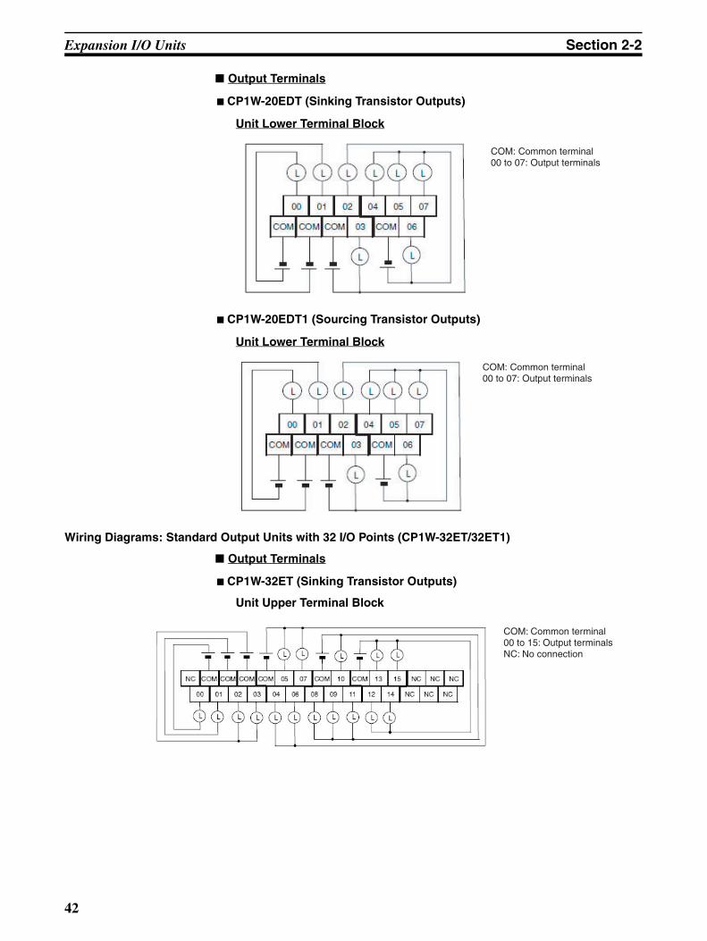
Expansion I/O Units Section 2-2
Output Terminals
CP1W-20EDT (Sinking Transistor Outputs)
Unit Lower Terminal Block
CP1W-20EDT1 (Sourcing Transistor Outputs)
Unit Lower Terminal Block
Wiring Diagrams: Standard Output Units with 32 I/O Points (CP1W-32ET/32ET1)
Output Terminals
CP1W-32ET (Sinking Transistor Outputs)
Unit Upper Terminal Block
COM: Common terminal00 to 07: Output terminals
COM: Common terminal00 to 07: Output terminals
COM: Common terminal00 to 15: Output terminalsNC: No connection
42

Expansion I/O Units Section 2-2
Unit Lower Terminal Block
CP1W-32ET1 (Sourcing Transistor Outputs)
Unit Upper Terminal Block
Unit Lower Terminal Block
COM: Common terminal16 to 31: Output terminalsNC: No connection
COM: Common terminal00 to 15: Output terminalsNC: No connection
COM: Common terminal16 to 31: Output terminalsNC: No connection
43

Expansion I/O Units Section 2-2
2-2-3 I/O SpecificationsThis section describes the I/O specifications of Expansion I/O Units.
Input Specifications (CP1W-20EDT/20EDT1)
* The response time is the delay caused by hardware.
Precautions for Safe Use
Do not apply voltage in excess of the rated voltage to the input terminal.
Item Specification
Input voltage 24 VDC, +10%, -15%
Input impedance 4.7 kΩInput current 5 mA typical
ON voltage 14.4 VDC min.
OFF voltage 5.0 VDC max.
ON response time 1 ms max.*
OFF response time 1 ms max.*
Circuit configuration
Internal circuits
Input indicatorIN
IN
COM
4.7kΩ
750Ω
44

Expansion I/O Units Section 2-2
Output Specifications for Transistor Outputs (Sinking or Sourcing)
*1 If the ambient temperature is maintained below 50°C, up to 0.9 A/com-mon can be used.
*2 The fuse cannot be replaced by the user. Replace the Unit if the fusebreaks due to a short-circuit or overcurrent.
Precautions for Safe Use
Do not connect a load to an output terminal or apply a voltage in excess of themaximum switching capacity.
Item Specification
CP1W-20EDT/20EDT1 CP1W-32ET/32ET1
Maximum switching capacity*1
24 VDC +10%/-5%0.3 A/output
4.5 to 30 VDC0.3 A/output
0.9 A/common1.8 A/Unit
0.9 A/common7.2 A/Unit
Leakage current 0.1 mA max. 0.1 mA max.
Residual voltage 1.5 V max. 1.5 V max.
ON response time 0.1 ms max. 0.1 ms max.
OFF response time 1 ms max.At 24 VDC +10%/ -5%, 5 to 300 mA
1 ms max.At 24 VDC +10%/ -5%, 5 to 300 mA
Maximum number of simultaneously ON outputs
8 points (100% load) 24 points (75% load)
Fuse*2 1 fuse/common
Circuit configuration
L
L
Output indicator
Internal circuits
COM (-)
OUT
OUT24 VDC/ 4.5 to 30 VDC
Sinking Outputs (CP1W-20EDT and CP1W-32ET)
L
L
Output indicator
Internal circuits
COM (+)
OUT
OUT
Sourcing Outputs (CP1W-20EDT1 and CP1W-32ET1)
24 VDC/ 4.5 to 30 VDC
0.9
0.8
(A)
0
Ambient temperature
50 55 (˚C)
Tota
l cur
rent
per
com
mon
45
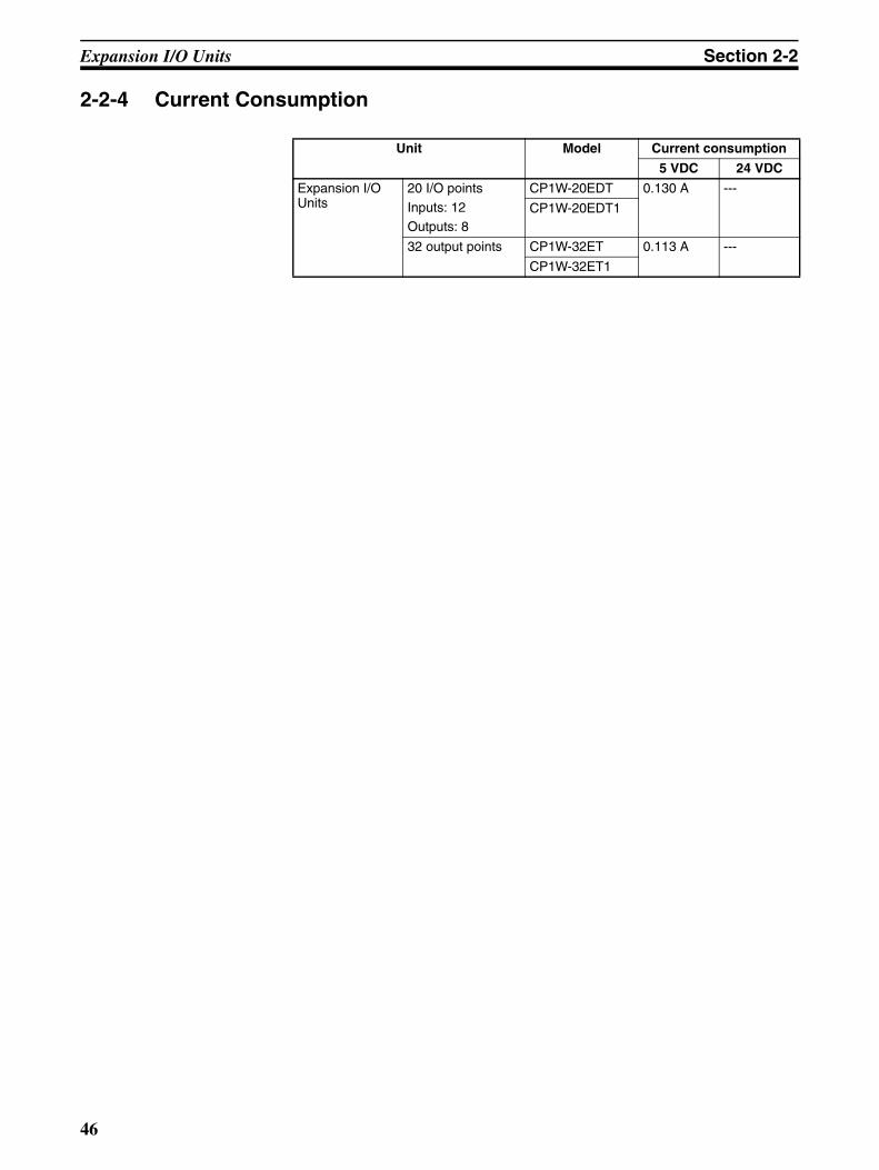
Expansion I/O Units Section 2-2
2-2-4 Current Consumption
Unit Model Current consumption
5 VDC 24 VDC
Expansion I/O Units
20 I/O points
Inputs: 12Outputs: 8
CP1W-20EDT 0.130 A ---
CP1W-20EDT1
32 output points CP1W-32ET 0.113 A ---
CP1W-32ET1
46

Option Units Section 2-3
2-3 Option UnitsThe section describes the part names, connector arrangement, communica-tions specifications, and other information on Option Units.Refer to 4-1 Installation and 4-2 Wiring for dimensions and weights.
2-3-1 RS-232C Option Board (CP1W-CIF01)
Part Names and Connector Arrangement
Communications Status IndicatorThis indicator flashes during serial communications.
RS-232C Connector
Precautions for Correct Use
Always turn OFF the power supply to the G9SP-series Controller beforemounting or removing Option Boards.
Communications SpecificationsOnly no-protocol communications can be used for RS-232C serial communi-cations of the G9SP-series Controller. Refer to SECTION 7 Communicationswith a Standard PLC Using an Option Board for the communications settingsof the connected Standard PLC.
COMM
Front Rear
1. Communications status indicator
3. Controller connector
2. RS-232C connector
5
6
1
9
Pin Abbr. Signal Signal direction
1 FG Frame ground ---
2 SD (TXD) Send data Outputs
3 RD (RXD) Receive data Inputs
4 RS (RTS) Request to send Outputs
5 CS (CTS) Clear to send Inputs
6 5 V Power ---
7 DR (DSR) Data set ready Inputs
8 ER (DTR) Data terminal ready
Outputs
9 SG (0 V) Signal ground ---
Connector hood
FG Frame ground ---
47
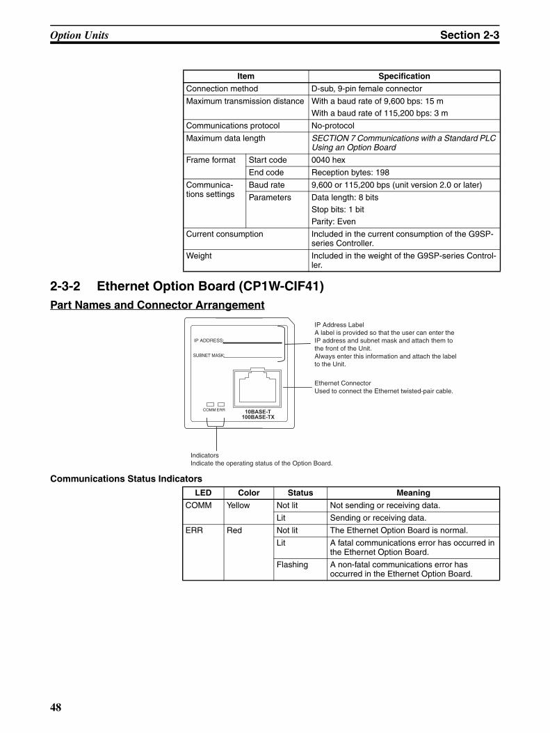
Option Units Section 2-3
2-3-2 Ethernet Option Board (CP1W-CIF41)Part Names and Connector Arrangement
Communications Status Indicators
Item Specification
Connection method D-sub, 9-pin female connector
Maximum transmission distance With a baud rate of 9,600 bps: 15 mWith a baud rate of 115,200 bps: 3 m
Communications protocol No-protocol
Maximum data length SECTION 7 Communications with a Standard PLC Using an Option Board
Frame format Start code 0040 hex
End code Reception bytes: 198
Communica-tions settings
Baud rate 9,600 or 115,200 bps (unit version 2.0 or later)
Parameters Data length: 8 bits
Stop bits: 1 bit
Parity: Even
Current consumption Included in the current consumption of the G9SP-series Controller.
Weight Included in the weight of the G9SP-series Control-ler.
IP ADDRESS:
SUBNET MASK:
COMM ERR10BASE-T
100BASE-TX
IP Address Label A label is provided so that the user can enter the IP address and subnet mask and attach them to the front of the Unit. Always enter this information and attach the label to the Unit.
Ethernet Connector Used to connect the Ethernet twisted-pair cable.
Indicators Indicate the operating status of the Option Board.
LED Color Status Meaning
COMM Yellow Not lit Not sending or receiving data.
Lit Sending or receiving data.
ERR Red Not lit The Ethernet Option Board is normal.
Lit A fatal communications error has occurred in the Ethernet Option Board.
Flashing A non-fatal communications error has occurred in the Ethernet Option Board.
48
Option Units Section 2-3
Precautions for Correct Use
• Only CP1W-CIF41 Ethernet Option Boards with unit version 2.0 or later canbe used. If another Option Board is used, the G9SP-series Controller willdetect an Unsupported Option Board Error (the MS indicator will flash red).
• Always turn OFF the power supply to the G9SP-series Controller beforemounting or removing Option Boards.
Communications SpecificationsOnly the UDP/IP protocol can be used for Ethernet communications with theG9SP-series Controller. Refer to SECTION 7 Communications with a Stan-dard PLC Using an Option Board for the communications settings of the con-nected Standard PLC.
Ethernet Communications Specifications
Note Communications with OMRON PLCs can be performed using the FINS/UDPprotocol.
2-3-3 Memory Cassette (CP1W-ME05M)Refer to SECTION 11 Backup and Restore Data Using Memory Cassette forinformation on using a Memory Cassette with the G9SP-series Controller.
Item Specifications
Type 100Base-TX (can be used as 10Base-T)
Transmis-sion specifi-cations
Media access method
CSMA/CD
Modulation method Baseband
Transmission paths Star form
Baud rate 100 Mbit/s (100Base-TX) 10 Mbit/s (10Base-T)
The internal baud rate between the G9SP-series Controller and Ethernet Option Board is 115.2 kbps.
Transmission media Unshielded twisted-pair (UTP) cable Categories: 5, 5e
Shielded twisted-pair (STP) cable Categories: 100 Ω at 5, 5e
Unshielded twisted-pair (UTP) cable Categories: 3, 4, 5, 5e
Shielded twisted-pair (STP) cable Categories: 100 Ω at 3, 4, 5, 5e
Transmission dis-tance
100 m (distance between hub and node)
Number of cascade connections
No restrictions in using switching hubs
Current consumption 130 mA max. at 5 V DC
Vibration resistance Conforms to JIS 0040.10 to 57Hz: 0.075-mm amplitude, 57 to 150 Hz: acceleration 9.8 m/s2 in X, Y, and Z directions for 80 minutes each (sweep time: 8 minutes × 10 sweeps = 80 minutes)
Shock resistance Conforms to JIS 0041.147 m/s2, 3 times each in X, Y, and Z directions
Ambient operating temperature 0 to 55°CAmbient humidity 10% to 90% (with no condensation)
Atmosphere Must be free of corrosive gas.
Ambient storage temperature -20 to 75°CWeight 23 g max.
Dimensions 36.4×36.4×28.2 mm (W×H×D)
49

Option Units Section 2-3
50

Hardware Settings
SECTION 3Calculating Response Performance
This section describes the startup time and reaction time of the G9SP-series Controller.
3-1 Startup Time . . . . . . . . . . . . . . . . . . . . . . . . . . . . . . . . . . . . . . . . . . . . . . . . . . 52
3-2 Reaction Times . . . . . . . . . . . . . . . . . . . . . . . . . . . . . . . . . . . . . . . . . . . . . . . . 53
3-2-1 Reaction Time Concepts . . . . . . . . . . . . . . . . . . . . . . . . . . . . . . . . . . 53
3-2-2 Local Input and Local Output Reaction Times. . . . . . . . . . . . . . . . . 53
51
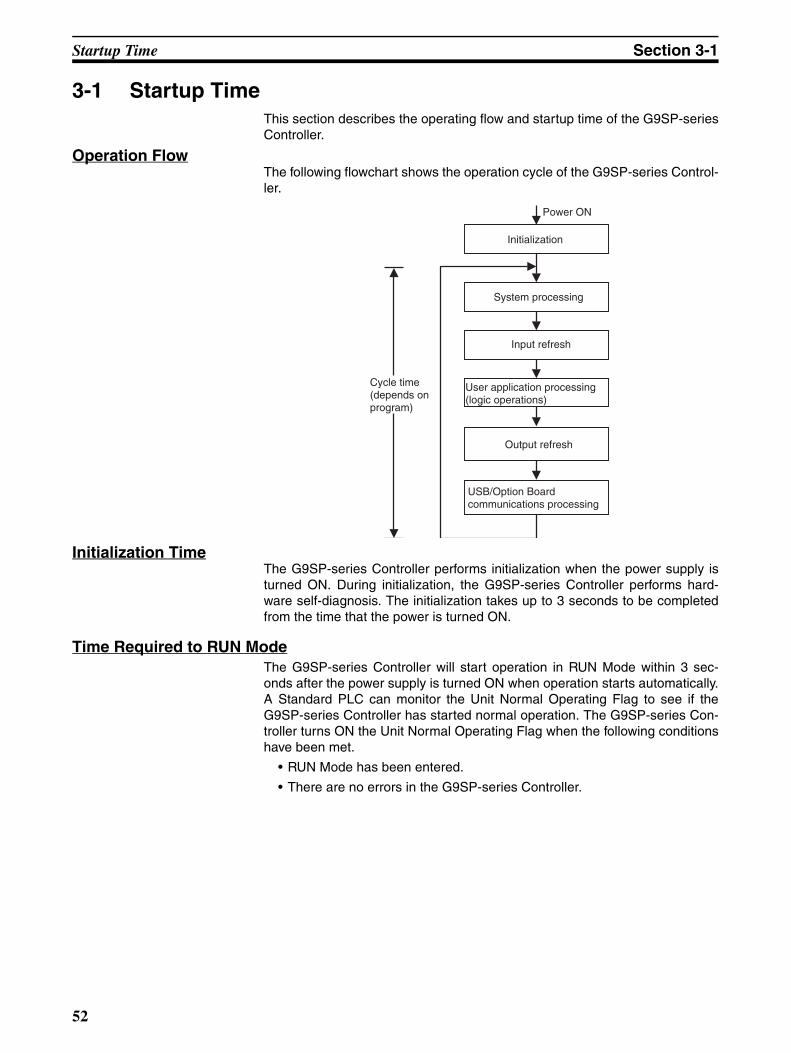
Startup Time Section 3-1
3-1 Startup TimeThis section describes the operating flow and startup time of the G9SP-seriesController.
Operation FlowThe following flowchart shows the operation cycle of the G9SP-series Control-ler.
Initialization TimeThe G9SP-series Controller performs initialization when the power supply isturned ON. During initialization, the G9SP-series Controller performs hard-ware self-diagnosis. The initialization takes up to 3 seconds to be completedfrom the time that the power is turned ON.
Time Required to RUN ModeThe G9SP-series Controller will start operation in RUN Mode within 3 sec-onds after the power supply is turned ON when operation starts automatically.A Standard PLC can monitor the Unit Normal Operating Flag to see if theG9SP-series Controller has started normal operation. The G9SP-series Con-troller turns ON the Unit Normal Operating Flag when the following conditionshave been met.
• RUN Mode has been entered.
• There are no errors in the G9SP-series Controller.
Power ON
Initialization
System processing
Input refresh
User application processing (logic operations)
Output refresh
USB/Option Board communications processing
Cycle time (depends on program)
52
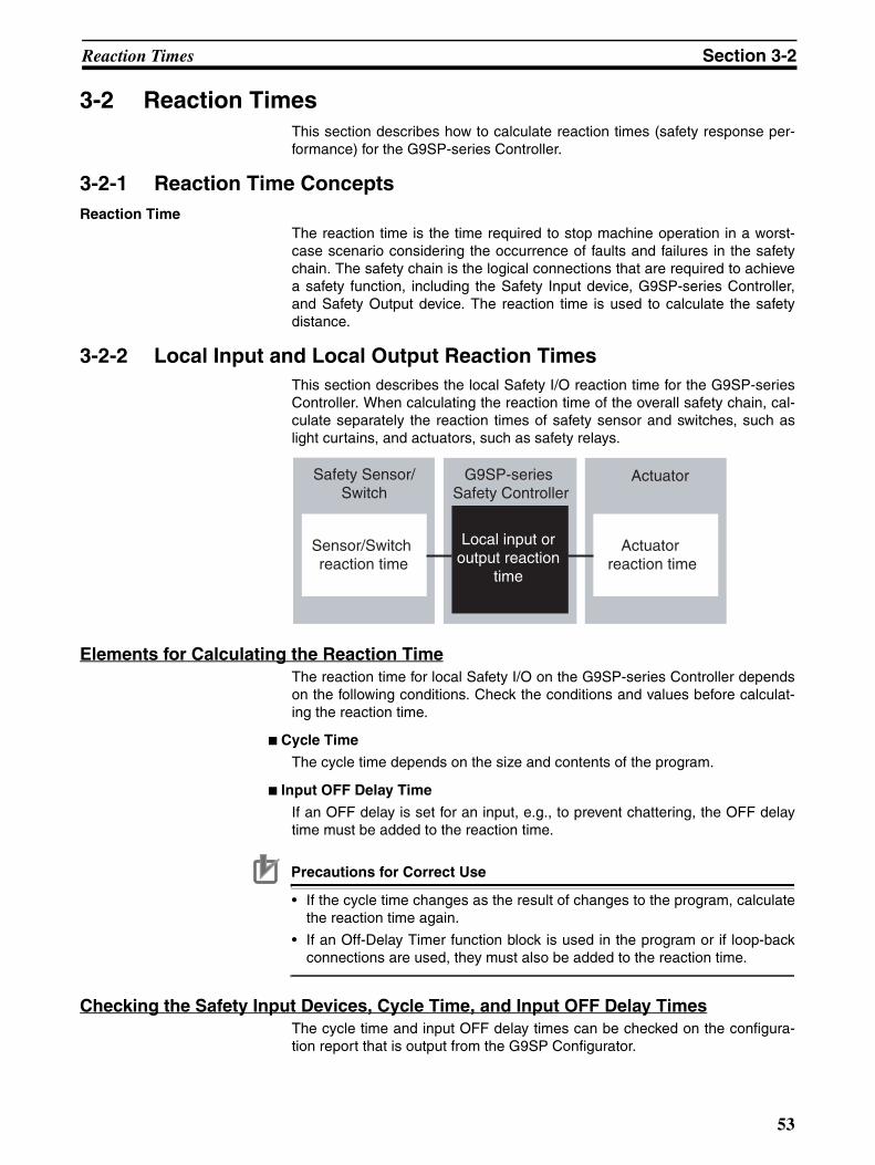
Reaction Times Section 3-2
3-2 Reaction Times This section describes how to calculate reaction times (safety response per-formance) for the G9SP-series Controller.
3-2-1 Reaction Time ConceptsReaction Time
The reaction time is the time required to stop machine operation in a worst-case scenario considering the occurrence of faults and failures in the safetychain. The safety chain is the logical connections that are required to achievea safety function, including the Safety Input device, G9SP-series Controller,and Safety Output device. The reaction time is used to calculate the safetydistance.
3-2-2 Local Input and Local Output Reaction TimesThis section describes the local Safety I/O reaction time for the G9SP-seriesController. When calculating the reaction time of the overall safety chain, cal-culate separately the reaction times of safety sensor and switches, such aslight curtains, and actuators, such as safety relays.
Elements for Calculating the Reaction TimeThe reaction time for local Safety I/O on the G9SP-series Controller dependson the following conditions. Check the conditions and values before calculat-ing the reaction time.
Cycle Time
The cycle time depends on the size and contents of the program.
Input OFF Delay Time
If an OFF delay is set for an input, e.g., to prevent chattering, the OFF delaytime must be added to the reaction time.
Precautions for Correct Use
• If the cycle time changes as the result of changes to the program, calculatethe reaction time again.
• If an Off-Delay Timer function block is used in the program or if loop-backconnections are used, they must also be added to the reaction time.
Checking the Safety Input Devices, Cycle Time, and Input OFF Delay TimesThe cycle time and input OFF delay times can be checked on the configura-tion report that is output from the G9SP Configurator.
G9SP-series Safety Controller
Safety Sensor/ Switch
Actuator
Sensor/Switch reaction time
Actuator reaction time
Local input or output reaction
time
53
Reaction Times Section 3-2
Reaction Time FormulaThe formula for calculating reaction time for local Safety I/O on the G9SP-series Controller is given below.
!WARNING Serious injury may possibly occur due to loss of required safety functions.Confirm that the calculated reaction times meet the required specifications forall safety chains.
Additional Information
The safety sensor/switch reaction times are given below for when OMRONSafety Sensors or Switches are connected directly to the G9SP-series Con-troller.
E3ZS or E3FS Single Beam Safety Sensor: 10 msD40A Non-contact Switch: 6 ms+0.4 ms × Number of connected SwitchesD40Z Non-contact Switch: 6 ms + (Cycle time × 2) ms UM Safety Mat: 10 ms
Local Safety I/O reaction time = (Cycle time × 2) − 2 + Input OFF delay time [ms]
54

Hardware Settings
SECTION 4Installation and Wiring
This section describes how to install and wire the G9SP-series Controller.
4-1 Installation. . . . . . . . . . . . . . . . . . . . . . . . . . . . . . . . . . . . . . . . . . . . . . . . . . . . 56
4-1-1 Installation Location . . . . . . . . . . . . . . . . . . . . . . . . . . . . . . . . . . . . . 56
4-1-2 Unit Arrangement . . . . . . . . . . . . . . . . . . . . . . . . . . . . . . . . . . . . . . . 58
4-1-3 Installation . . . . . . . . . . . . . . . . . . . . . . . . . . . . . . . . . . . . . . . . . . . . 59
4-1-4 Connecting Expansion I/O Units and Expansion Units . . . . . . . . . . 60
4-1-5 Mounting Option Boards . . . . . . . . . . . . . . . . . . . . . . . . . . . . . . . . . 62
4-2 Wiring . . . . . . . . . . . . . . . . . . . . . . . . . . . . . . . . . . . . . . . . . . . . . . . . . . . . . . . 63
4-2-1 Wire Sizes . . . . . . . . . . . . . . . . . . . . . . . . . . . . . . . . . . . . . . . . . . . . . 63
4-2-2 Wiring the Power Supply . . . . . . . . . . . . . . . . . . . . . . . . . . . . . . . . . 64
55

Installation Section 4-1
4-1 InstallationThis section provides precautions on the environmental factors that must beconsidered and the installation location of each G9SP-series Unit.
4-1-1 Installation Location
Installation EnvironmentDo not install the G9SP-series Controller in the following locations.
• Locations subject to ambient temperatures lower than 0°C or higher than55°C.
• Locations subject to condensation as the result of severe changes in tem-perature.
• Locations subject to ambient humidity lower than 10% or higher than90%.
• Locations subject to corrosive or flammable gases.
• Locations subject to excessive dust, salt, or metal filings.
• Locations subject to direct shock or vibration.
• Locations subject to direct sunlight.
• Locations subject to water, oil, or chemicals.
Always enclose or protect the G9SP-series Controller sufficiently in the follow-ing locations.
• Locations subject to static electricity or other forms of noise.
• Locations subject to strong electromagnetic fields.
• Locations subject to possible exposure to radioactivity.
• Locations close to power lines.
Installation in Control PanelsWhen the G9SP-series Controller is being installed in a control panel, be sureto provide proper ambient conditions as well as access for operation andmaintenance.
Installation OrientationWhen installing the G9SP-series Controller in a control panel, it must beinstalled with the side with indicators and communications ports facing thefront to ensure proper heat dissipation.
56
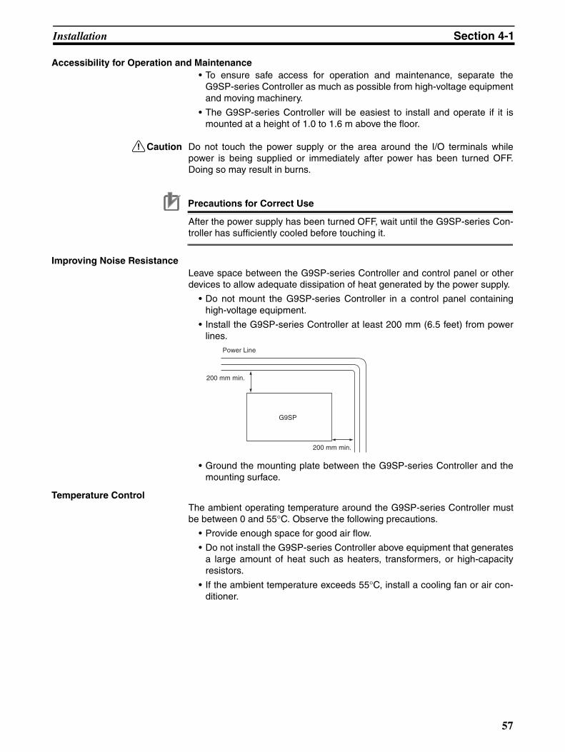
Installation Section 4-1
Accessibility for Operation and Maintenance• To ensure safe access for operation and maintenance, separate the
G9SP-series Controller as much as possible from high-voltage equipmentand moving machinery.
• The G9SP-series Controller will be easiest to install and operate if it ismounted at a height of 1.0 to 1.6 m above the floor.
!Caution Do not touch the power supply or the area around the I/O terminals whilepower is being supplied or immediately after power has been turned OFF.Doing so may result in burns.
Precautions for Correct Use
After the power supply has been turned OFF, wait until the G9SP-series Con-troller has sufficiently cooled before touching it.
Improving Noise ResistanceLeave space between the G9SP-series Controller and control panel or otherdevices to allow adequate dissipation of heat generated by the power supply.
• Do not mount the G9SP-series Controller in a control panel containinghigh-voltage equipment.
• Install the G9SP-series Controller at least 200 mm (6.5 feet) from powerlines.
• Ground the mounting plate between the G9SP-series Controller and themounting surface.
Temperature ControlThe ambient operating temperature around the G9SP-series Controller mustbe between 0 and 55°C. Observe the following precautions.
• Provide enough space for good air flow.
• Do not install the G9SP-series Controller above equipment that generatesa large amount of heat such as heaters, transformers, or high-capacityresistors.
• If the ambient temperature exceeds 55°C, install a cooling fan or air con-ditioner.
G9SP
200 mm min.
200 mm min.
Power Line
57
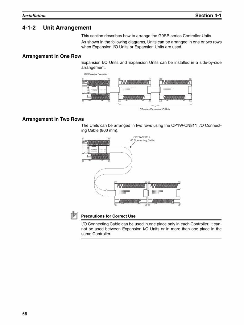
Installation Section 4-1
4-1-2 Unit ArrangementThis section describes how to arrange the G9SP-series Controller Units.
As shown in the following diagrams, Units can be arranged in one or two rowswhen Expansion I/O Units or Expansion Units are used.
Arrangement in One RowExpansion I/O Units and Expansion Units can be installed in a side-by-sidearrangement.
Arrangement in Two RowsThe Units can be arranged in two rows using the CP1W-CN811 I/O Connect-ing Cable (800 mm).
Precautions for Correct Use
I/O Connecting Cable can be used in one place only in each Controller. It can-not be used between Expansion I/O Units or in more than one place in thesame Controller.
CP-series Expansion I/O Units
G9SP-series Controller
CP1W-CN811 I/O Connecting Cable
58

Installation Section 4-1
4-1-3 InstallationThis section describes how to install the G9SP-series Controller.
Dimensions and Installation Height
Dimensions
Installation HeightThe installation height is approximately 90 mm.
When a Connecting Cable is connected to an Option Board, however, theadditional height must be included. Always allow for the additional heightwhen considering the depth of the control panel in which the G9SP-seriesController is to be mounted.
Installation MethodsThere are two installation methods.
DIN Track InstallationThe Units can be mounted to PEP-50N (50 cm) or PEP-100N/100N2 (100cm) DIN Tracks. Secure the DIN Track with screws in at least three places.
Surface InstallationUnits can be directly mounted in the control panel using M4 screws.
Model number A B Weight
G9SP-N10S 86 76 290 g max.
G9SP-N10D 130 120 440 g max.
G9SP-N20S 130 120 430 g max.
88185
AB
90100110
Four, 4.5 dia.
DIN Track
Secure with screws
59

Installation Section 4-1
Mounting Brackets
DIN TrackSecure the DIN Track to the control panel using M4 screws at interval of210 mm or less (6 holes or fewer). The tightening torque is 1.2 N·m.
End Plates
Use the PFP-M End Plates to secure the Units so that they do not movetowards one end or the other of the DIN Track.
Mounting with Screws1. Open mounting holes in the mounting surface according to the dimensions
diagram.
2. Use M4 screws, which fit the holes on the G9SP-series Controller. Thetightening torque is 1.2 N·m.
4-1-4 Connecting Expansion I/O Units and Expansion UnitsThis section describes how to connect Expansion I/O Units and ExpansionUnits.
Connection Methods
1,2,3... 1. Remove the cover from the G9SP-series Controller’s or the Expansion I/OUnit’s expansion connector. Use a flat-head screwdriver to remove the cov-er from the Expansion I/O Connector.
1510
4.5
25 25 2510
25 151000
1000 (500)*
PFP-100N2
PFP-100N/50N
1510
4.5
25 25 2510
25 15(5)* 1
16
1.51
29.22427
28-25 × 4.5 long holes
30±0.3
7.3±0.15
35±0.3 27±0.15
*PFP-50N dimensions are given in parentheses.
Expansion Connector Cover
(1) Remove
60

Installation Section 4-1
2. Insert the Expansion I/O Unit’s connecting cable into the G9SP-seriesG9SP-series Controller’s or the Expansion I/O Unit’s expansion connector.
3. Attach the cover to the G9SP-series Controller’s or the Expansion I/OUnit’s expansion connector.
Precautions for Correct Use
• Always turn OFF the power supply to the G9SP-series Controller beforemounting or removing Expansion I/O Units.
• Separate the G9SP-series Controller from the Expansion I/O Units by about10 mm.
Precautions on Connecting UnitsThe following restrictions apply to the Expansion I/O Units that can be con-nected to the G9SP-series Controller.
Applicable ModelsRefer to 1-1-2 Basic System and Configuration Devices and 2-2 ExpansionI/O Units for information on the Expansion I/O Units that can be connected.
Maximum Number of Connectable UnitsUp to two Expansion I/O Units can be connected.
Configuration Data AgreementIf the actual configuration does not agree with the configuration data, a non-fatal error will occur in the G9SP-series Controller. Correct the configurationor the configuration data so that they agree. Refer to SECTION 13 Trouble-shooting for information on errors.
(2) Insert
(3) Attach
61

Installation Section 4-1
4-1-5 Mounting Option BoardsThis section describes how to mount an Option Board.
Mounting and Removal
Mounting
1,2,3... 1. Turn OFF the power supply to the G9SP-series Controller.
2. Remove the cover to the Option Board slot. If you squeeze the top and bot-tom lock levers on the cover together to release the lock, you can removethe cover.
3. Make sure the Board is in the correct orientation and firmly press it into theslot until it clicks into place.
RemovalAlways turn OFF the power supply before removing an Option Board. If yousqueeze the top and bottom lock levers on the Option Board together torelease the lock, you can remove the Option Board.
Precautions for Correct Use
Always turn OFF the power supply to the G9SP-series Controller beforemounting or removing Option Boards.
Precautions When Connecting an Option BoardThe following restrictions apply to the Option Boards that can be mounted tothe G9SP-series Controller.
Applicable ModelsRefer to 1-1-2 Basic System and Configuration Devices for information on theExpansion I/O Units that can be connected.
Maximum Number of BoardsOnly one Option Board can be mounted.
62

Wiring Section 4-2
4-2 Wiring This section describes wiring methods for the G9SP-series Controller andCP-series Expansion I/O Units.
4-2-1 Wire SizesUse the following wires to wire the power supply and external I/O devices tothe G9SP-series Controller.
* When wiring two wires to one terminal, use two wires of the same type andthickness.
• M3 self-rising terminals are used on the screw terminals. Tighten the ter-minal block screws to the torque of 0.5 N·m.
• Use crimp terminals (M3) having the dimensions shown below.
Precautions for Safe Use
• Disconnect the G9SP-series Controller from the power supply before start-ing wiring. Devices connected to the Controller may operate unexpectedly.
• Properly apply the specified voltage to the G9SP-series Controller powersupply and input terminals. Applying an inappropriate DC voltage or any ACvoltage may result in failure of specified functions, reduced safety functions,damage to the product, and burning.
• Never apply a voltage that exceeds the input voltage for Input Units or themaximum switching capacity for Output Units.
• When the power supply has positive and negative terminals, always wirethem correctly.
• Be sure to separate the communications cables and I/O cables from high-voltage/high-current lines.
• Do not bend a cable past its natural bending radius or pull in it with exces-sive force. Doing so will damage the cable.
• Be careful not to get your fingers caught when attaching terminal blocks tothe G9SP-series Controller.
• Incorrect wiring may lead to loss of safety functions. Wire conductors cor-rectly and verify the operation of the G9SP-series Controller before usingthe system in which the Controller is incorporated.
Solid wire 0.32 to 0.82 mm2, AWG22 to AWG18
0.32 to 0.5 mm2, AWG22 to AWG20*
Stranded wire 0.5 to 1.3 mm2, AWG20 to AWG16
0.5 to 0.82 mm2, AWG20 to AWG18*
6.2 mm max. 6.2 mm max.
63

Wiring Section 4-2
4-2-2 Wiring the Power Supply
Wiring the Power SupplyThe G9SP-series Controller provides power terminals V1/G1 for the internaland input circuits and power terminals V2/G2 for the output circuits.
Use a power supply with a voltage fluctuation range of 20.4 to 26.4 VDC.
• If the voltage may drop due to the starting current or inrush current foroutput devices, use different power sources for the two power supplies.
• When using more than one G9SP-series Controller, use separate powersupply circuits for each G9SP-series Controller to prevent the malfunctionof breakers and voltage drops from inrush current.
Power Supply SelectionUse a DC power supply satisfying the following requirements.
• The secondary circuit of the DC power supply must be isolated from theprimary circuit by double insulation or reinforced insulation.
• An isolated power supply that is limited to a current of 8 A or lower mustbe used.
• The output hold time must be 20 ms or longer.
• The DC power supply must be a SELV power supply that satisfies therequirements of IEC/EN 60950-1 and EN 50178.
Power Supply Grounding• Ground the 0-V side of the power supply terminals (G1 and G2) to enable
detecting faults for disconnected I/O wiring or ground faults.
• Ground to 100 Ω or less to provide stronger noise immunity.
• Do not share ground lines with other equipment or ground to structuralparts of buildings to prevent adverse influences.
Precautions for Safe Use
• Connect the positive and negative terminals correctly.
• Supply power to all of the Power Supply Units from the same source.
D+
D−
USB
Inte
rnal
Circ
uit
Safety Input CircuitTest Output Circuit
Safety Output Circuit
Standard Output Circuit
24 VDCV1
G1
Si0
Si19
T0
T5
V2
G2
So0
So7
O0
O3
L
L
L
L
64
Wiring Section 4-2
Precautions for Correct Use
• Wiring clippings can scatter when wiring. Leave the label attached to thetop of the Unit when wiring to prevent the entry of foreign matter.
• Remove the label after the completion of wiring to ensure proper heat dissi-pation.
65

Wiring Section 4-2
66

Software Design
SECTION 5Preparations for Using the G9SP Configurator
This section describes the features and provides the installation procedure for the G9SP Configurator. The G9SPConfigurator is a software application that is used to program and debug a G9SP-series Controller.
5-1 Overview . . . . . . . . . . . . . . . . . . . . . . . . . . . . . . . . . . . . . . . . . . . . . . . . . . . . . 68
5-1-1 System Requirements and System Configuration . . . . . . . . . . . . . . 68
5-1-2 G9SP Configurator Functions. . . . . . . . . . . . . . . . . . . . . . . . . . . . . . 69
5-2 Installation. . . . . . . . . . . . . . . . . . . . . . . . . . . . . . . . . . . . . . . . . . . . . . . . . . . . 70
5-2-1 Installing the G9SP Configurator . . . . . . . . . . . . . . . . . . . . . . . . . . . 70
5-2-2 Installing the USB Driver . . . . . . . . . . . . . . . . . . . . . . . . . . . . . . . . . 70
67
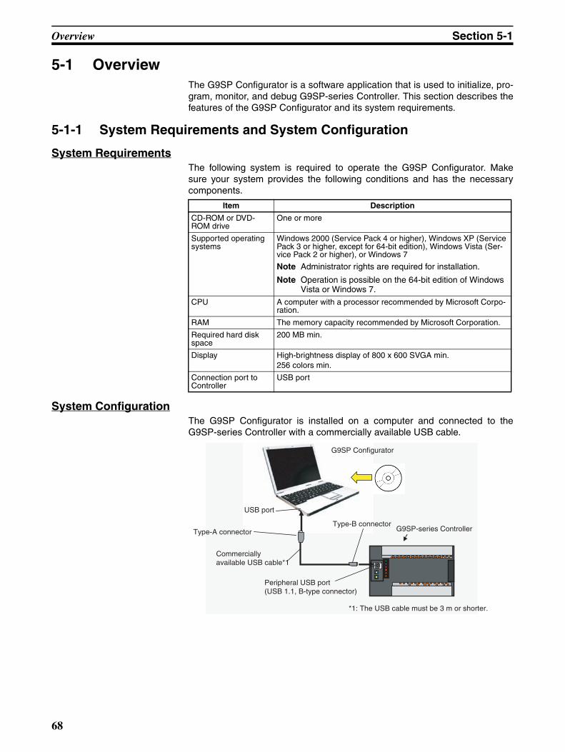
Overview Section 5-1
5-1 OverviewThe G9SP Configurator is a software application that is used to initialize, pro-gram, monitor, and debug G9SP-series Controller. This section describes thefeatures of the G9SP Configurator and its system requirements.
5-1-1 System Requirements and System Configuration
System RequirementsThe following system is required to operate the G9SP Configurator. Makesure your system provides the following conditions and has the necessarycomponents.
System ConfigurationThe G9SP Configurator is installed on a computer and connected to theG9SP-series Controller with a commercially available USB cable.
Item Description
CD-ROM or DVD-ROM drive
One or more
Supported operating systems
Windows 2000 (Service Pack 4 or higher), Windows XP (Service Pack 3 or higher, except for 64-bit edition), Windows Vista (Ser-vice Pack 2 or higher), or Windows 7
Note Administrator rights are required for installation.
Note Operation is possible on the 64-bit edition of Windows Vista or Windows 7.
CPU A computer with a processor recommended by Microsoft Corpo-ration.
RAM The memory capacity recommended by Microsoft Corporation.
Required hard disk space
200 MB min.
Display High-brightness display of 800 x 600 SVGA min.256 colors min.
Connection port to Controller
USB port
G9SP Configurator
USB port
Peripheral USB port (USB 1.1, B-type connector)
Commercially available USB cable*1
Type-A connectorType-B connector
G9SP-series Controller
*1: The USB cable must be 3 m or shorter.
68
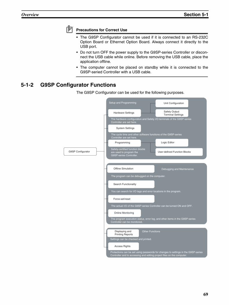
Overview Section 5-1
Precautions for Correct Use
• The G9SP Configurator cannot be used if it is connected to an RS-232COption Board or Ethernet Option Board. Always connect it directly to theUSB port.
• Do not turn OFF the power supply to the G9SP-series Controller or discon-nect the USB cable while online. Before removing the USB cable, place theapplication offline.
• The computer cannot be placed on standby while it is connected to theG9SP-seried Controller with a USB cable.
5-1-2 G9SP Configurator FunctionsThe G9SP Configurator can be used for the following purposes.
Setup and Programming
G9SP Configurator
Debugging and Maintenance
Safety Output Terminal Settings
Unit Configuration
Logic Editor
User-defined Function Blocks
Hardware Settings
System Settings
Programming
Offline Simulation
Online Monitoring
Other FunctionsDisplaying and Printing Reports
Access Rights
Force-set/reset
The program can be debugged on the computer.
The actual I/O of the G9SP-series Controller can be turned ON and OFF.
Search Functionality
You can search for I/O tags and error locations in the program.
Settings can be checked and printed.
Safety-certified function blocks are used to program the G9SP-series Controller.
The hardware configuration and Safety I/O terminals of the G9SP-series Controller are set here.
The cycle time and other software functions of the G9SP-series Controller are set here.
The program execution status, error log, and other items in the G9SP-series Controller can be monitored.
Protections can be set using passwords for changes to settings in the G9SP-series Controller and to accessing and editing project files on the computer.
69
Installation Section 5-2
5-2 InstallationThis section describes the installation procedure that must be performed touse the G9SP Configurator.
Precautions for Correct Use
To install the software, log on as a user that meets the following conditions.
• Administrator privileges
• Only single-byte alphanumeric characters in the user's account name (ver-sion 1.00 only)
5-2-1 Installing the G9SP Configurator
Preparing for InstallationCheck the following items before beginning with the installation.
Available Hard Disk SpaceThe G9SP Configurator can be installed on the hard disk only. At least 200MB of hard disk space is required. Make sure that there is enough spaceavailable.
Windows Environment and Installation DestinationThe G9SP Configurator is a software application for a Windows operatingenvironment. The software is installed on Windows. Make sure that Windowsis installed and functioning correctly on the computer.
Installation ProcedureThis section describes how to install the software on a computer using the fol-lowing drive configuration as an example.
C drive: Hard disk drive
D drive: CD-ROM drive
1,2,3... 1. Start Windows and insert the G9SP Configurator Master Disk in the CD-ROM drive. The installation program will be started by the computer’s auto-run function. If the installation program does not start, select Specify FileName and Run from the Windows Start Menu, enter “d:\setup” and clickthe OK Button.
2. Complete the installation process following the instructions provided on-screen.
Uninstalling the G9SP ConfiguratorUninstall the G9SP Configurator when it is no longer required. Uninstall theapplication using Add and Remove Applications in the control panel.
5-2-2 Installing the USB DriverThe USB driver for the G9SP-series Controller must be installed on the com-puter running the G9SP Configurator in order to connect the G9SP-seriesController to the computer via USB. The USB driver is stored in the followingdirectory in the computer when the G9SP Configurator is installed.
\Drivers\USB in the installation folder
70
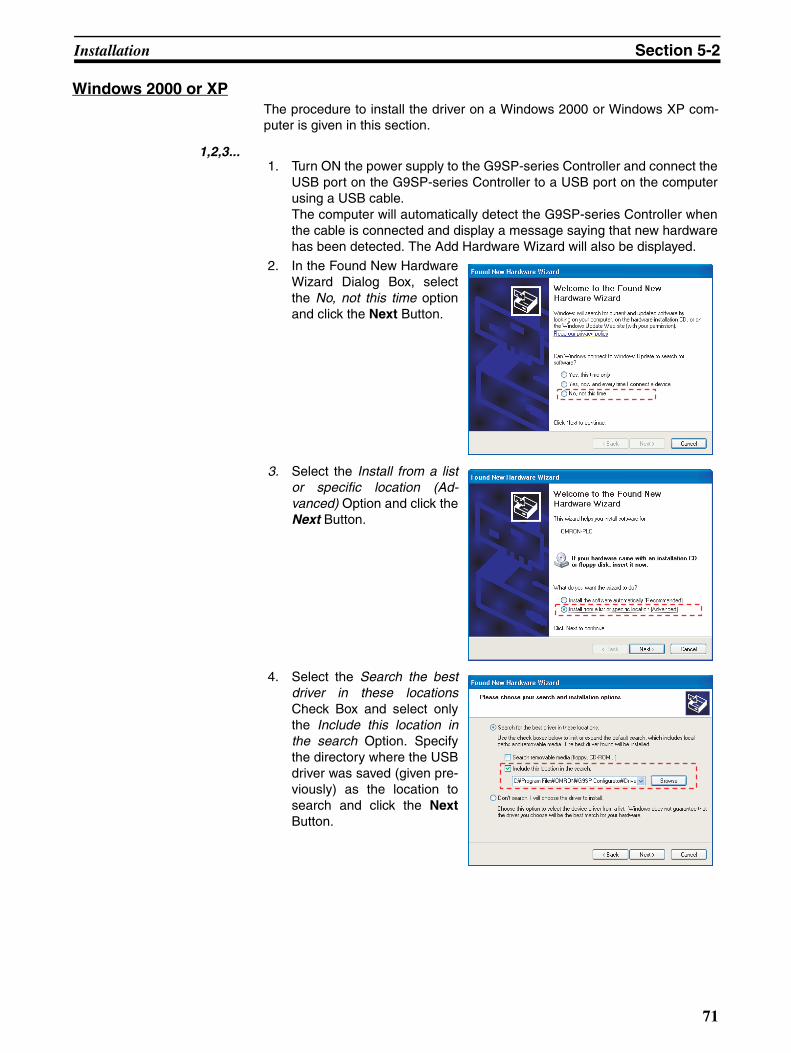
Installation Section 5-2
Windows 2000 or XPThe procedure to install the driver on a Windows 2000 or Windows XP com-puter is given in this section.
1,2,3...1. Turn ON the power supply to the G9SP-series Controller and connect the
USB port on the G9SP-series Controller to a USB port on the computerusing a USB cable.The computer will automatically detect the G9SP-series Controller whenthe cable is connected and display a message saying that new hardwarehas been detected. The Add Hardware Wizard will also be displayed.
2. In the Found New HardwareWizard Dialog Box, selectthe No, not this time optionand click the Next Button.
3. Select the Install from a listor specific location (Ad-vanced) Option and click theNext Button.
4. Select the Search the bestdriver in these locationsCheck Box and select onlythe Include this location inthe search Option. Specifythe directory where the USBdriver was saved (given pre-viously) as the location tosearch and click the NextButton.
71
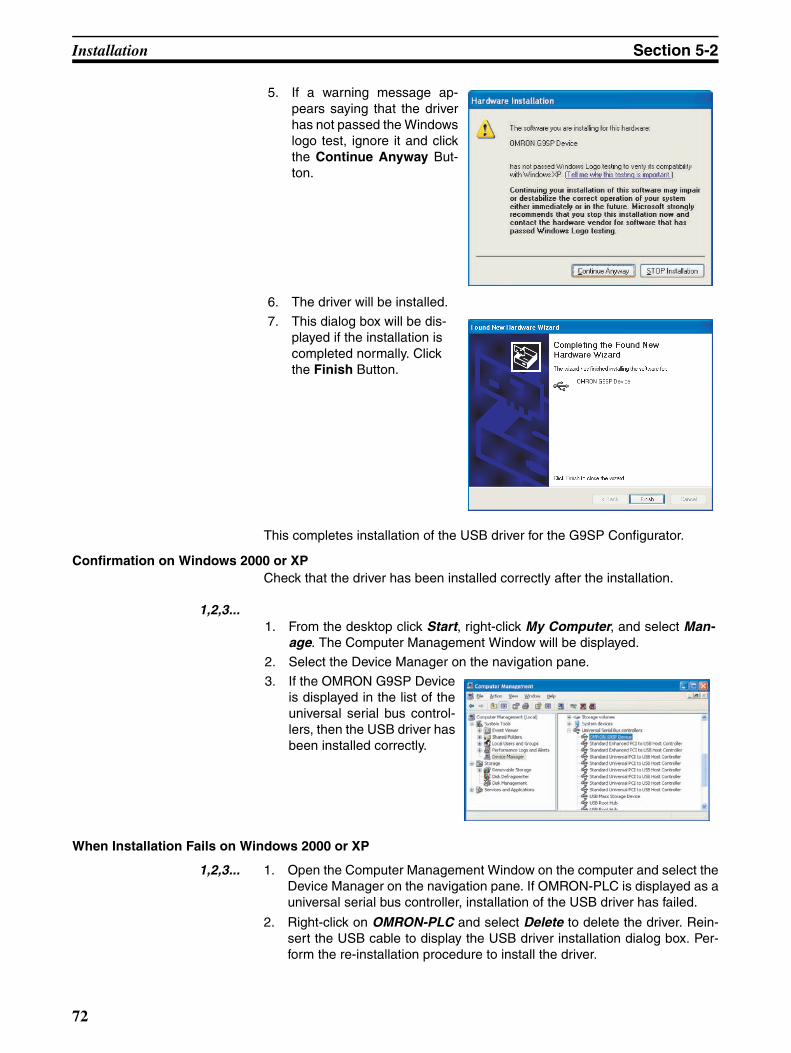
Installation Section 5-2
This completes installation of the USB driver for the G9SP Configurator.
Confirmation on Windows 2000 or XPCheck that the driver has been installed correctly after the installation.
1,2,3...
When Installation Fails on Windows 2000 or XP
1,2,3... 1. Open the Computer Management Window on the computer and select theDevice Manager on the navigation pane. If OMRON-PLC is displayed as auniversal serial bus controller, installation of the USB driver has failed.
2. Right-click on OMRON-PLC and select Delete to delete the driver. Rein-sert the USB cable to display the USB driver installation dialog box. Per-form the re-installation procedure to install the driver.
5. If a warning message ap-pears saying that the driverhas not passed the Windowslogo test, ignore it and clickthe Continue Anyway But-ton.
6. The driver will be installed.
7. This dialog box will be dis-played if the installation is completed normally. Click the Finish Button.
1. From the desktop click Start, right-click My Computer, and select Man-age. The Computer Management Window will be displayed.
2. Select the Device Manager on the navigation pane.
3. If the OMRON G9SP Deviceis displayed in the list of theuniversal serial bus control-lers, then the USB driver hasbeen installed correctly.
72

Installation Section 5-2
Windows VistaThe procedure to install the driver on a Windows Vista computer is given inthis section.
1,2,3...1. Turn ON the power supply to the G9SP-series Controller and connect the
USB port on the G9SP-series Controller to a USB port on the computerusing a USB cable.The Add Hardware Wizard will also be displayed.
2. Select the Locate and installdriver software Option.
3. Click the Don’t search onlineOption in the Found NewHardware Dialog Box.
4. Select the following: I don’thave the disc. Show me oth-er options.
73

Installation Section 5-2
This completes installation of the USB driver for the G9SP Configurator.
Confirmation on Windows VistaCheck that the driver has been installed correctly after the installation.
1,2,3...
5. Select the Browse my com-puter for driver software (ad-vanced) Option.
6. Click the Browse Button,specify the directory wherethe USB driver was saved(given previously) as the lo-cation to search and click theNext Button.
7. The Windows Security Dia-log Box will be displayed.Click the Install Button.
8. The driver will be installed.
9. When the driver installationis completed normally, theinstallation completed dialogbox will be displayed. Clickthe Close Button.
1. From the desktop click Start, right-click Computer, and select Manage.The Computer Management Window will be displayed.
74

Installation Section 5-2
When Installation Fails on Windows Vista
1,2,3... 1. Display the Device Manager on the computer. If OMRON-PLC is displayedin other devices, installation of the USB driver has failed.
2. Right-click on OMRON-PLC and select Delete to delete the driver. Rein-sert the USB cable to display the USB driver installation dialog box. Per-form the re-installation procedure to install the driver.
Installing on Windows 7The procedure to install the driver on a Windows 7 computer is given in thissection.
1,2,3...
2. Select the Device Manager on the navigation pane.
3. If the OMRON G9SP Deviceis displayed in the list of uni-versal serial bus controllers,then the USB driver hasbeen installed correctly.
1. Turn ON the power supply to the G9SP-series Controller and connect theUSB port on the G9SP-series Controller to a USB port on the computerusing a USB cable.
2. Right-click Computer on theStart Menu, and then selectManage.
3. The Computer Management Window will be displayed. Select the Device Manager on the navigation pane. Right-click OMRON-PLC under Other Devices, and then select Update Driver Software.
75

Installation Section 5-2
This completes installation of the USB driver for the G9SP Configurator.
Confirmation on Windows 7Check that the driver has been installed correctly after the installation.
1,2,3...
4. The Update Driver SoftwareDialog Box will be displayed.Select the Browse my com-puter for driver software Op-tion.
5. Click the Browse Button un-der Search for driver soft-ware in this location. Specifythe directory where the USBdriver was saved (\Driv-ers\USB) as the location tosearch and click the NextButton.
6. The Windows Security Dia-log Box will be displayed.Click the Install Button.
7. The driver will be installed.
8. When the driver installationis completed normally, theinstallation completed dialogbox will be displayed. Clickthe Close Button.
1. Right-click Computer on the Start Menu, and then select Manage.
76

Installation Section 5-2
When Installation Fails on Windows 7Repeat the procedure for installing the driver on Windows 7.
2. Select the Device Manager on the navigation pane.
3. If the OMRON G9SP Deviceis displayed in the list of uni-versal serial bus controllers,then the USB driver hasbeen installed correctly.
77

Installation Section 5-2
78

Software Design
SECTION 6Creating Configuration Data
This section describes the procedures for creating configuration data for G9SP-series Controllers using the G9SPConfigurator.
6-1 Overview . . . . . . . . . . . . . . . . . . . . . . . . . . . . . . . . . . . . . . . . . . . . . . . . . . . . . 80
6-2 Creating Configuration Data . . . . . . . . . . . . . . . . . . . . . . . . . . . . . . . . . . . . . . 81
6-2-1 Starting the G9SP Configurator . . . . . . . . . . . . . . . . . . . . . . . . . . . . 81
6-2-2 Hardware Settings. . . . . . . . . . . . . . . . . . . . . . . . . . . . . . . . . . . . . . . 81
6-2-3 Programming . . . . . . . . . . . . . . . . . . . . . . . . . . . . . . . . . . . . . . . . . . 83
6-2-4 System Settings. . . . . . . . . . . . . . . . . . . . . . . . . . . . . . . . . . . . . . . . . 86
6-2-5 Displaying and Printing Reports. . . . . . . . . . . . . . . . . . . . . . . . . . . . 87
6-3 Designing Device Security . . . . . . . . . . . . . . . . . . . . . . . . . . . . . . . . . . . . . . . 88
6-4 Offline Simulation. . . . . . . . . . . . . . . . . . . . . . . . . . . . . . . . . . . . . . . . . . . . . . 93
6-4-1 Basic Procedure . . . . . . . . . . . . . . . . . . . . . . . . . . . . . . . . . . . . . . . . 93
6-4-2 Convenient Usage to Increase Debugging Efficiency. . . . . . . . . . . . 94
6-5 Creating and Using User-defined Function Blocks. . . . . . . . . . . . . . . . . . . . . 97
6-5-1 Application Examples. . . . . . . . . . . . . . . . . . . . . . . . . . . . . . . . . . . . 97
6-5-2 Specifications . . . . . . . . . . . . . . . . . . . . . . . . . . . . . . . . . . . . . . . . . . 98
6-5-3 Operation Rights. . . . . . . . . . . . . . . . . . . . . . . . . . . . . . . . . . . . . . . . 98
6-5-5 Creating User-defined Function Blocks . . . . . . . . . . . . . . . . . . . . . . 99
6-5-6 Exporting User-defined Function Blocks . . . . . . . . . . . . . . . . . . . . . 100
6-5-7 Importing User-defined Function Blocks . . . . . . . . . . . . . . . . . . . . . 101
79

Overview Section 6-1
6-1 OverviewConfiguration data for the G9SP-series Controller is created using the G9SPConfigurator.
G9SP Configurator Screen
Basic WorkflowConfiguration data for the G9SP-series Controller is created basically usingthe following workflow.
1. Starting the G9SP Configurator.
2. Hardware setup (e.g., selecting I/O devices to connect in the unit configu-ration)
3. Programming
4. System settings
5. Displaying and printing reports
6. Designing device security
7. Desktop debugging (i.e., analysis and offline simulation using searches)
Project Window: This window serves as the basis for all operations on the G9SP Configurator.
Function Block List Window:This window displays a list of the function blocks that can be used in the program.
I/O Tag List Window:This window displays a list of I/O tags that can be used in the program.
Output Window:This window displays the results of operations performed on the G9SP Configurator.
Operation Guide Window:This window displays information on startup procedures for the G9SP-series Safety Controllers.
Program Window:This window is where programs are created.
80

Creating Configuration Data Section 6-2
6-2 Creating Configuration DataFirst, start the G9SP Configurator, and then make the hardware settings, per-form programming, and make the system settings, in that order.
6-2-1 Starting the G9SP Configurator1,2,3... 1. Select Programs/All Programs - OMRON G9SP Configurator - G9SP
Configurator from the Windows Start Menu.
2. Select Create New Project or Open Existing File from the Startup Oper-ation Selection Guide.
Precautions for Correct Use
• You must have administrator rights to manipulate user-defined functionblocks.Refer to 6-5-4 Starting the G9SP Configurator When Manipulating User-defined Function Blocks.
This section describes how to create a new project using an example fromAppendix A Emergency Stop Pushbutton Application.
6-2-2 Hardware SettingsFirst, make the hardware settings for the G9SP-series Controller.
1,2,3... 1. Unit Configuration
Drag and drop the model of the G9SP-series Controller and the ExpansionI/O Units to connect. It is not necessary to select the option board to con-nect.
2. Selecting I/O Devices to Connect
Select the external devices to connect to the Safety I/O terminals. Also,edit the I/O comments and test sources. For details on Safety I/O function-ality, refer to 2-1-5 Safety Inputs and 2-1-6 Safety Outputs.
Settings can be performed while confirming the current setup phase.
You can drag and drop the G9SP-series Controller and the Expansion I/O Units.
You can jump to any setup display by clicking one of the buttons.
Overall configuration information is displayed.
81

Creating Configuration Data Section 6-2
Safety Output Terminals
First, drag and drop the external devices to connect to the Safety Output ter-minals.
Safety Input Terminals
Next, drag and drop the external devices to connect to the Safety Input termi-nals.
Note (1) For an I/O comment, you can use up to 48 single-byte characters, exceptfor the following characters: \ / : * ? “ < > | % #.
(2) If an Ethernet Communications Option Board is used, TCP/IP settings,such as the IP address, must be made in the system settings. In thatcase, T3 cannot be used as the test pulse output terminal.
Drag and drop 2 Safety Relays with welding check. At the same time, you can also set the Safety Input terminal to use to input feedback.
I/O device settings are displayed.
I/O comments are edited. In this example, the comments are entered to enable differentiating between KM1 and KM2 in the program.
Drag and drop Emergency Stop Switch (2NC) and Reset Switch.
An ON/OFF delay for the input filter can be set by clicking the Advance Edit Button. A delay of up to 1,000 ms can be set.
I/O comments are edited. In this example, the comments are entered to enable differentiating between S1, S2, and KM1_KM2 in the program.
Select the Test Output terminal to connect to the Safety Input terminal. In this example, the test sources for Si2 and Si3 are set for different terminals than for Si0 and Si1 so that short-circuits between the terminals can be detected.
82
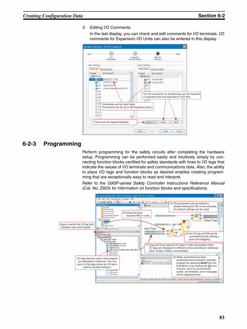
Creating Configuration Data Section 6-2
3. Editing I/O Comments
In the last display, you can check and edit comments for I/O terminals. I/Ocomments for Expansion I/O Units can also be entered in this display.
6-2-3 ProgrammingPerform programming for the safety circuits after completing the hardwaresetup. Programming can be performed easily and intuitively simply by con-necting function blocks certified for safety standards with lines to I/O tags thatindicate the values of I/O terminals and communications data. Also, the abilityto place I/O tags and function blocks as desired enables creating program-ming that are exceptionally easy to read and interpret.
Refer to the G9SP-series Safety Controller Instructions Reference Manual(Cat. No. Z923) for information on function blocks and specifications.
Comments can be input freely.(Comments can be up to 48 characters each.)
The I/O comments for all terminals can be imported or exported from and exported to CSV files.
Terms can be replaced globally.
(1) Drag and drop required I/O tags in order and position them. I/O tags are displayed in different colors according to attributes: Input, Output, Safety, and standard.
(2) Drag and drop required FBs in order.
(3) An I/O tag and FB can be connected by left-clicking a point and dragging.
(4) FB parameters can be edited by double-clicking the FB. In this example, the default settings can be used.
(5) When everything has been positioned and connected, build the program by selecting Build from the Edit Menu or by clicking the Icon. If errors, such as unconnected points, are detected, error messages will be displayed here.
Input Tags
Output Tags
Used to switch the I/O tag lists between input and outputs.
I/O tags that are used in the program are displayed in bold text. You can
jump to the page where an I/O tag is used by double-clicking it.
83

Creating Configuration Data Section 6-2
I/O Tags
What Are I/O Tags?I/O tags are I/O data that reflect the values of I/O terminals and communica-tions data. Tags called I/O comments can be used to identify the tags to allowprogramming without concern for address allocations in the G9SP-seriesController.
I/O Tags Supported in ProgrammingRefer to 1-1-2 I/O Tags in the G9SP-series Safety Controller Instructions Ref-erence Manual (Cat. No. Z923).
Relation to I/O CommentsI/O comments that are set for I/O terminals are reflected in the I/O tags. In thisexample, Emergency Stop NC S1 11-12 and an I/O comment are set forSafety Input terminal Si0, and so that name is reflected in the input tags.
Convenient Functions to Increase Programming EfficiencyThis section describes functions that are convenient for increasing program-ming efficiency.
Text Boxes and Function Block CommentsText and function block comments can be added as desired to improve pro-gram legibility.
Program comments and other text can be pasted.
Text colors and background colors can also be specified.
84

Creating Configuration Data Section 6-2
Page and Jump TagsA program can be created using up to 16 pages. Programming can be createdfor better legibility and analysis by dividing pages according to functions likeemergency stops and controller status monitoring or according to location,such as robot A and control panel B. Jump tags (64 jumps max.) are used totransfer data between pages.
Search FunctionalitySearch functionality is included to aid program analysis.
Searching for Used I/O Tags
I/O tags that are being used are displayed in bold text in the I/O tag list. Whenyou double-click one of these, the display will jump to the page where the tagis used, and the I/O tag will flash red. Also, when you double-click a jump tag,the display jumps to the linked jump tag.
Searching for Text Strings
You can search for an I/O tag or function block using a text string by selectingFind from the Edit Menu. When you double-click the search results, the dis-play will jump to the page where the I/O tag or function block is used, and theI/O tag or function block will flash red.
Searching for Program Error Locations
Build errors are displayed in the Output Window. When you click on an error,the display will jump to the relevant page, and the relevant I/O tag or functionblock will flash red.
User-defined Function BlocksYou can combine combinations of function blocks into one user-defined func-tion block. Converting frequently used combinations into user-defined functionblocks enables creating program components and standardization. It alsoimproves programming efficiency. Refer to 6-5 Creating and Using User-defined Function Blocks for details.
Programming PrecautionsThis section describes the minimum cautions to keep in mind when program-ming.
Building ProgramsPrograms created using the G9SP Configurator are converted to download-able data when the program is built. Building is executed automatically whendownloading starts, but it can also be executed manually to check the pro-
gram. (Select Build from the Edit Menu or click the Icon.) The program
capacity and program execution sequence (described below) are alsoupdated when the program is built.
Program SizeYou can check the size of the program at any time at the bottom of the display.Be careful not to exceed the maximum sizes (i.e., the denominators).
The GUI size is the size of the information required to display programs. Thisinformation includes information on function block locations, text boxes, etc.
85

Creating Configuration Data Section 6-2
Program Execution SequenceFunction blocks are executed sequentially for each page.
Loopback ConnectionsA loopback connection can be created by connecting the output terminal fromthe function block that comes later in the execution order to the input terminalto a function block that comes earlier in the execution order. A jump tag isused to make the loopback connection.
6-2-4 System SettingsSystem settings are performed only after programming has been completed.It is normally not necessary to change the system settings. Make the settingsin the following cases.
The system settings are accessed from the Project Window.
Manually Setting the Cycle Time
The G9SP Configurator calculates and automatically sets the minimum cycletime supported for operation according to the program contents and SafetyInput terminal settings. Therefore, the cycle time depends on the programcontent and capacity, and recalculation of safety response performance isrequired. This can be avoided by manually inputting the cycle time.
Prohibiting Using a Memory Cassette to Restore Memory
Change the system setting to use the prohibit restore setting described in 11-3 Restoring Data to G9SP-series Controller.
Executed from the top down.
Indicate the execution order on each page.
The Jump tag is used to make loopback connections.
The Jump tag turns ON when FB [2] is executed, so Output 1 (the result of FB [1]) turns ON one cycle later.
The settable cycle time range.
The minimum cycle time for operation.This time depends on the program contents.
86

Creating Configuration Data Section 6-2
Using a CP1W-CIF41 Ethernet Communications Board
TCP/IP settings, such as the IP address, must be made in the system settingsif an Ethernet Communications Option Board is used. Refer to 7-3 EthernetCommunications for details on settings.
6-2-5 Displaying and Printing ReportsA report (i.e., a configuration report) on the configuration data that has beenset is displayed on the computer screen to check setting details.
What Is a Report?The G9SP Configurator creates two types of reports. The characteristics ofeach type are given in the following table.
Note (1) Refer to 8-2-3 Verifying the Configuration Data for information on verifica-tion.
(2) The configuration report can be saved to a file by using commerciallyavailable PDF creation software.
Configuration Data Application Example
Documentation Showing the Configuration Data Contents
Forming the details of settings made with the G9SP Configurator into a reportenables using the data for other applications.
Notification to Hardware Designers
Hardware designers require information on the I/O terminal allocations, cycletime, and ON/OFF delay values to create wiring diagrams and to calculatesafety response performance. The report includes that information and can beused as documentation for notification of details.
Item Configuration report Verification report
Purpose • Documentation showing the configuration data contents.
• Notification to hardware designers.
Checking if the configuration data has been correctly down-loaded to the G9SP-series Controller.
Displayed contents Configuration data Verification results and config-uration data.
Printing Supported Supported
Saving to file Not supported Supported
Display timing When Print Preview is selected from the File Menu.
After executing Communica-tion - Verify.
87

Designing Device Security Section 6-3
6-3 Designing Device SecurityThis section describes how to set access restrictions with passwords to pre-vent improper access to project files created using the G9SP-series Controlleror G9SP Configurator.
Password Types and Application ExamplesThe following two types of passwords can be used.
Precautions for Correct Use
• For security, we recommend you set a device password and a project filepassword.
• There is no way to recover a parameter password if it has been lost, and soa project file with no set password must be separately saved if a parameterpassword is set.
• The parameter password is enabled when the project is downloaded to theG9SP-series Controller. Always download the project after setting the pass-word.
• Refer to 8-5 Setting a Device Password for information on measures whenthe device password is lost.
Project File RightsProject file rights are determined by the results of parameter password verifi-cation. The following describes the file rights.
Password type Description Timing of setting in G9SP-series Controller
Password entry
Parameter passwords
Editable Password to restrict editing of configuration data included in project file.
When downloaded.8-2 Downloading Configura-tion Data to the G9SP-series Controller and Verification
• When opening a project file.• When uploading.• When changing a parameter
password.Read only
Password to restrict reading.
Device password Password to restrict access to G9SP-series Controller.
When device password is changed.8-5 Setting a Device Pass-word
• When downloading.• When changing modes.• When locking the configura-
tion.• When resetting.• When device password is
changed.
Operation rights Meaning
Free A parameter password is not set.
Edit right The project file can be browsed and edited.
Read-only right The project file can be only browsed.
None The project file cannot be edited or browsed.The error log can be checked using the device monitor.
88

Designing Device Security Section 6-3
Using PasswordsThis section describes how to use passwords for the following typical cases.
Restricting Only Access to the G9SP-series ControllerSet only a device password.
Setting Procedure
Connect the G9SP-series Controller online and then set the device password.For details, refer to 8-5 Setting a Device Password.
Verification Procedure
The G9SP Configurator will prompt you to input the device password whendownloading or changing modes. Input the set device password.
Restricting Access to the G9SP-series Controller and Reading ParametersSet the parameter password for reading, parameter password for editing, anddevice password.
Passwords and main settings User rights
User A (e.g., design manager)
User B (e.g., equipment operator)
Passwords Parameter password edit right − −Parameter password read-only right − −Device password Allowed Not allowed
Main operations Editing parameters and programs Allowed Allowed
Reading parameters and programs, display-ing, printing, and verification reports
Allowed Allowed
Downloading, changing modes, resetting, and locking the configuration
Allowed Not allowed
Debugging with the program monitor Allowed Allowed
Debugging (e.g., error/operation logs) with the device monitor
Allowed Allowed
Changing the device password Allowed Not allowed
Passwords and main settings User rights
User A (e.g., design manager)
User B (e.g., mainte-nance per-sonnel)
User C (e.g., equipment operator)
Passwords Parameter password edit right Allowed Not allowed Not allowed
Parameter password read-only right − Not allowed Not allowed
Device password Allowed Allowed Not allowed
Main operations Editing parameters and programs Allowed Not allowed Not allowed
Reading parameters and programs, display-ing, printing, and verification reports
Allowed Not allowed Not allowed
Downloading, changing modes, resetting, and locking the configuration
Allowed Allowed Not allowed
Debugging with the program monitor Allowed Not allowed Not allowed
Debugging (e.g., error/operation logs) with the device monitor
Allowed Allowed Allowed
Changing the device password Allowed Allowed Not allowed
89

Designing Device Security Section 6-3
Setting Procedure
1,2,3... 1. In the following dialog box for changing the parameter password, enter thepresent parameter password for editing, present password for reading,new password for editing, and new password for reading. Enter the samepassword for editing and reading.
2. Connect the G9SP-series Controller online and then set the device pass-word.
Verification Procedure
1,2,3... 1. The G9SP Configurator will prompt you to input the parameter passwordwhen a project file is opened or configuration data is uploaded. Input theset password for editing and password for reading.The project file will open with the edit right if the passwords match. If thepasswords do not match and the Cancel Button is clicked, the project filewill open without rights.
2. The G9SP Configurator will prompt you to input the device password whendownloading or changing modes. Input the set device password.
Input the same password.
The password must be between 6 and 16 alphanumeric characters.Input the same password for editing and browsing.
The text box will be empty when no password is set.
Parameter password for
editing
Parameter password for reading
Project file operation rights
Match Edit right
Do not match None
90
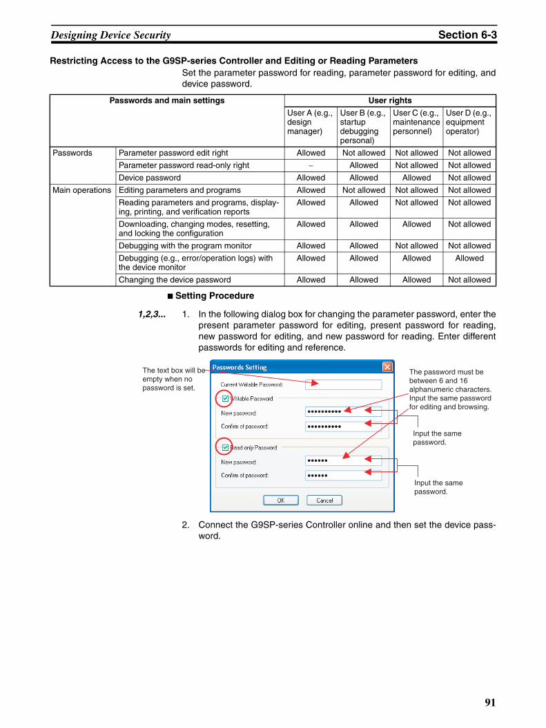
Designing Device Security Section 6-3
Restricting Access to the G9SP-series Controller and Editing or Reading ParametersSet the parameter password for reading, parameter password for editing, anddevice password.
Setting Procedure
1,2,3... 1. In the following dialog box for changing the parameter password, enter thepresent parameter password for editing, present password for reading,new password for editing, and new password for reading. Enter differentpasswords for editing and reference.
2. Connect the G9SP-series Controller online and then set the device pass-word.
Passwords and main settings User rights
User A (e.g., design manager)
User B (e.g., startup debugging personal)
User C (e.g., maintenance personnel)
User D (e.g., equipment operator)
Passwords Parameter password edit right Allowed Not allowed Not allowed Not allowed
Parameter password read-only right − Allowed Not allowed Not allowed
Device password Allowed Allowed Allowed Not allowed
Main operations Editing parameters and programs Allowed Not allowed Not allowed Not allowed
Reading parameters and programs, display-ing, printing, and verification reports
Allowed Allowed Not allowed Not allowed
Downloading, changing modes, resetting, and locking the configuration
Allowed Allowed Allowed Not allowed
Debugging with the program monitor Allowed Allowed Not allowed Not allowed
Debugging (e.g., error/operation logs) with the device monitor
Allowed Allowed Allowed Allowed
Changing the device password Allowed Allowed Allowed Not allowed
Input the same password.
The password must be between 6 and 16 alphanumeric characters.Input the same password for editing and browsing.
The text box will be empty when no password is set.
Input the same password.
91
Designing Device Security Section 6-3
Verification Procedure
1,2,3... 1. The G9SP Configurator will prompt you to input the parameter passwordwhen a project file is opened or configuration data is uploaded. Input theset password for editing or password for reading.
The project file will open with the edit right if the password matches the pa-rameter password for editing. The file will open with the read-only right ifthe password does not match the parameter password for editing but doesmatch the parameter password for reading. If the passwords matches nei-ther password and the Cancel Button is clicked, the project file will openwithout rights.
2. The G9SP Configurator will prompt you to input the device password whendownloading or changing modes. Input the set device password.
Parameter password for
editing
Parameter password for reading
Project file operation rights
Match (Verification skipped.) Edit right
Do not match Match Read-only right
Do not match Do not match None
92

Offline Simulation Section 6-4
6-4 Offline SimulationThe operation of the G9SP-series Controller's programming can be checkedby performing simulation on a computer.
Note Simulation cannot be used during online monitoring. Disconnect the onlineconnection before starting simulation.
6-4-1 Basic ProcedureThis section describes the basic procedure for simulation.
Starting Simulation
1,2,3... 1. Check that the G9SP Configurator is offline .
2. Click the Start Simulation Icon . The background of the Program Win-dow will turn pink.
Executing Simulation
1,2,3... 1. Click the Program Operation Icon .
2. Debug the program by selecting the desired I/O tag and then clicking the
Set Icon , Reset Icon , and Reverse Icon .
Start and stop simulation.
•Run/stop•Set/reset/reverse
You can change the values of any input tags to simulate the operation of the program.
Time ChartA time chart can be used to check operation for a previously set input pattern.
93

Offline Simulation Section 6-4
6-4-2 Convenient Usage to Increase Debugging EfficiencyThis section describes convenient applications to increase debugging effi-ciency using simulation.
Initial Value SettingsYou can set the initial values for input tags when execution of simulationstarts. This is useful when reproducing the actual system status or when eval-uating test cases using similar input status.
94
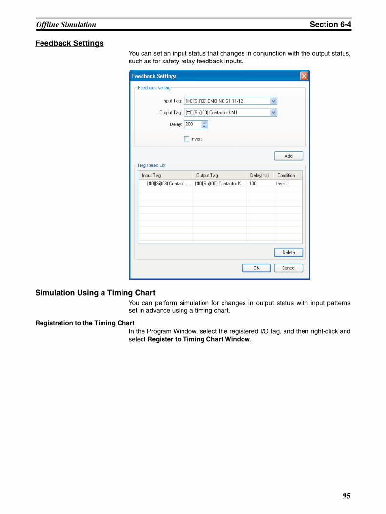
Offline Simulation Section 6-4
Feedback SettingsYou can set an input status that changes in conjunction with the output status,such as for safety relay feedback inputs.
Simulation Using a Timing ChartYou can perform simulation for changes in output status with input patternsset in advance using a timing chart.
Registration to the Timing ChartIn the Program Window, select the registered I/O tag, and then right-click andselect Register to Timing Chart Window.
95
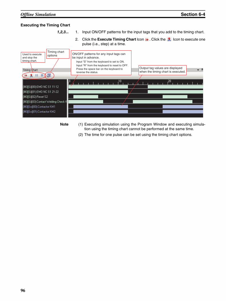
Offline Simulation Section 6-4
Executing the Timing Chart
1,2,3... 1. Input ON/OFF patterns for the input tags that you add to the timing chart.
2. Click the Execute Timing Chart Icon . Click the Icon to execute onepulse (i.e., step) at a time.
Note (1) Executing simulation using the Program Window and executing simula-tion using the timing chart cannot be performed at the same time.
(2) The time for one pulse can be set using the timing chart options.
ON/OFF patterns for any input tags can be input in advance.
Input "S" from the keyboard to set to ON. Input "R" from the keyboard to reset to OFF.
Used to execute and stop the timing chart.
Output tag values are displayed when the timing chart is executed.
Press the space bar on the keyboard to reverse the status.
Timing chart options
96

Creating and Using User-defined Function Blocks Section 6-5
6-5 Creating and Using User-defined Function BlocksThe function blocks provided by the G9SP Configurator can be combined bythe user to create new function blocks called user-defined function blocks.These user-defined function blocks can be used to reuse programming.
6-5-1 Application Examples
Unifying Programming in Different LocationsWhen the same programming is used in different locations, the programmingcan be defined as a user-defined function block. This reduces maintenancework when changes are required to the programming contained in the user-defined function block.
Reusing Programming from Other Project FilesUser-defined function blocks that were created in other project files can beimported and exported. This enables using programming that has alreadybeen debugged, to reduce programming work and improve quality.
Increasing Program Structure and ReadabilityAll of the function blocks used in a user-defined function block are seen asonly one function block. This helps to make programs more structured, whichmakes them more readable.
Precautions for Correct Use
• Using user-defined function blocks does not reduce the program size. Forexample, if a user-defined function block that contains five function blocks isused three times, the number of function blocks will be 5 times 3, or 15function blocks.
• To use user-defined function blocks, you must have Windows administratoror power user rights.
• You can register up to 256 user-defined function blocks in the Project Win-dow.
• You can create up to 16 folders in the User-defined Function Block folder.
• You can use up to 48 characters in a user-defined function block name,page name, or folder name.
• You can use between 6 and 16 alphanumeric characters in the editable orread only password.
• You can position up to 128 user-defined function blocks in the Editor.
A user-defined function block is created for this part.
97

Creating and Using User-defined Function Blocks Section 6-5
6-5-2 SpecificationsThe specifications of user-defined function blocks are given below.
6-5-3 Operation RightsOperation rights for user-defined function blocks include a password and acti-vation key. Restrictions in user-defined function block operations are givenbelow.
An activation key is used to prevent unintentional importing of user-definedfunction blocks.
To set operation rights, right-click the function block that you created in theProject Window. Operation rights can also be set when creating a new user-defined function block.
6-5-4 Starting the G9SP Configurator When Manipulating User-defined Function Blocks
You must have administrator rights to create, edit, save, delete, or import user-defined function blocks. To achieve this, use the following procedure to startthe G9SP Configurator.
Windows 2000 or Windows XP
1,2,3... 1. Log on as a user with administrator rights.
2. Start the G9SP Configurator.
Windows Vista or Windows 7
1,2,3... 1. Select Programs (All Programs) - OMRON G9SP Configurator from theWindows Start Menu.
2. Right-click G9SP Configurator.
3. Select Run as administrator from the pop-up menu that is displayed.
Item Specification
Maximum number of I/O terminals Input terminals: 32, Output terminals: 16
Maximum number of function blocks 128
Maximum number of pages 32
Maximum number of jump tags 64
I/O comment size 48 alphanumeric characters
Nesting user-defined function blocks Not supported
Editable Accessing and
monitoring
Importing
Passwords Editable OK OK OK
Read only --- OK OK
Activation key --- --- OK
98
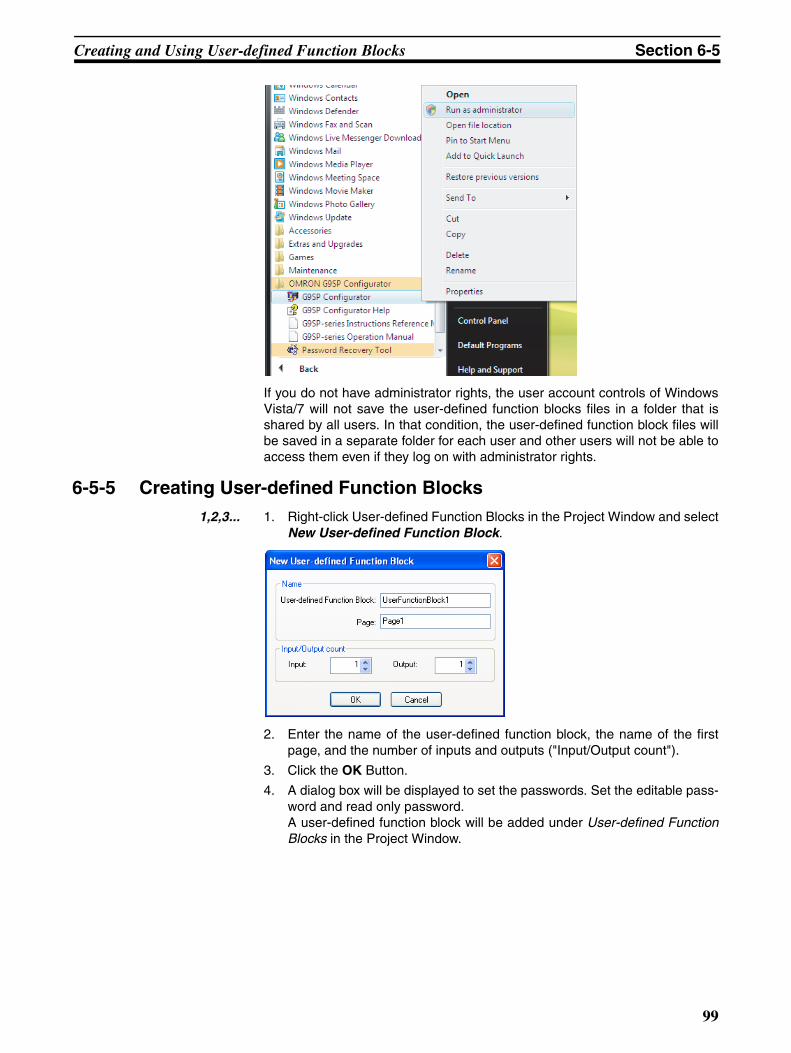
Creating and Using User-defined Function Blocks Section 6-5
If you do not have administrator rights, the user account controls of WindowsVista/7 will not save the user-defined function blocks files in a folder that isshared by all users. In that condition, the user-defined function block files willbe saved in a separate folder for each user and other users will not be able toaccess them even if they log on with administrator rights.
6-5-5 Creating User-defined Function Blocks1,2,3... 1. Right-click User-defined Function Blocks in the Project Window and select
New User-defined Function Block.
2. Enter the name of the user-defined function block, the name of the firstpage, and the number of inputs and outputs ("Input/Output count").
3. Click the OK Button.
4. A dialog box will be displayed to set the passwords. Set the editable pass-word and read only password. A user-defined function block will be added under User-defined FunctionBlocks in the Project Window.
99

Creating and Using User-defined Function Blocks Section 6-5
Additional Information
• The password must be between 6 and 16 alphanumeric characters. The fol-lowing characters cannot be used in user-defined function block names:
\ / : * ? " < > | % # .
• If the OK Button is clicked with no password set, the function block will nothave a password and anyone can access and edit it.
5. Create the programming.Double-click the page in the user-defined function block and create theprogramming as usual by placing and connecting function blocks.
6. Save the user-defined function block. Select User-defined Function Block - Save from the File Menu. When a user-defined function block that is used in the program is editedand saved, the user-defined function blocks that are used in the programwill change immediately.
Additional Information
Previously created programming can be converted to user-defined functionblocks.
Procedure: Right-click the page to be converted to a function block under theProgram folder in the Project Window and select Register as User-definedFunction Block.
6-5-6 Exporting User-defined Function BlocksUser-defined function blocks can be exported and used in other project files.
Precautions for Correct Use
Test the operation of user-defined function blocks sufficiently before distribut-ing them for application.
100
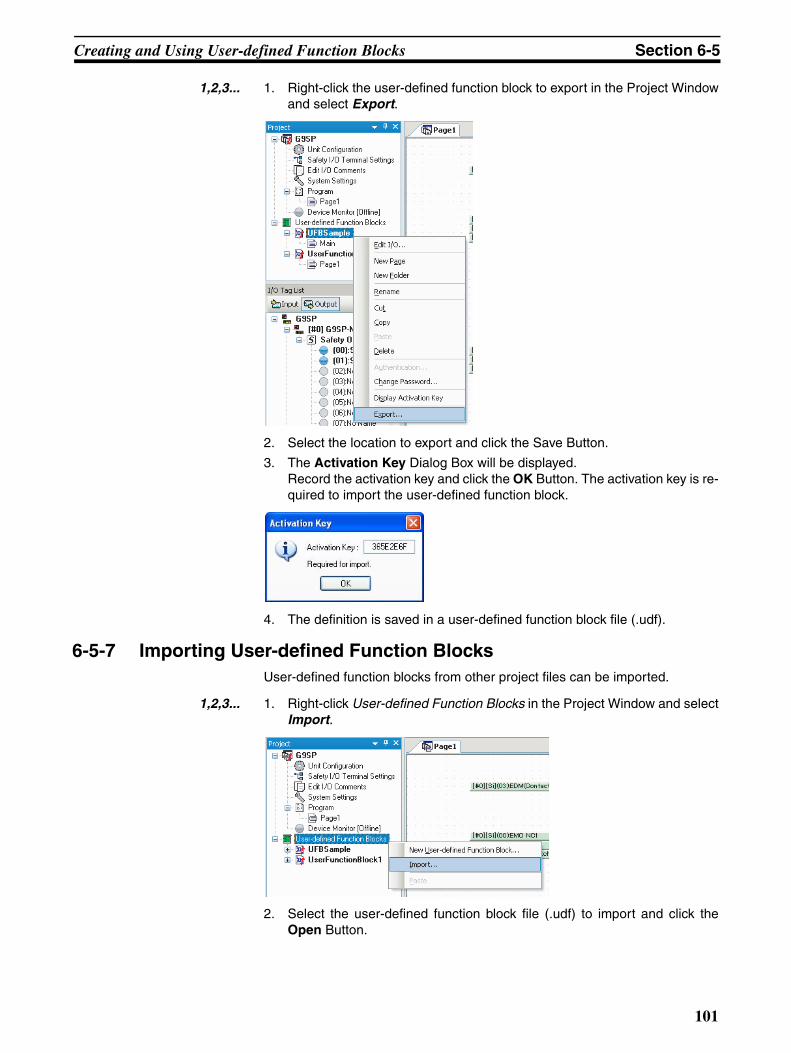
Creating and Using User-defined Function Blocks Section 6-5
1,2,3... 1. Right-click the user-defined function block to export in the Project Windowand select Export.
2. Select the location to export and click the Save Button.
3. The Activation Key Dialog Box will be displayed.Record the activation key and click the OK Button. The activation key is re-quired to import the user-defined function block.
4. The definition is saved in a user-defined function block file (.udf).
6-5-7 Importing User-defined Function BlocksUser-defined function blocks from other project files can be imported.
1,2,3... 1. Right-click User-defined Function Blocks in the Project Window and selectImport.
2. Select the user-defined function block file (.udf) to import and click theOpen Button.
101

Creating and Using User-defined Function Blocks Section 6-5
3. The Input Authentication Dialog Box will be displayed.Select the activation key of the user-defined function block to import andclick the OK Button. You can also import the user-defined function block by entering the pass-word.
4. The user-defined function block will be imported and displayed in theProject Window.
102

Software Design
SECTION 7Communications with a Standard PLC Using an Option Board
This section describes how to perform communications with a Standard PLC through an RS-232C Option Board orEthernet Option Board.
7-1 Functionality for All Option Board's . . . . . . . . . . . . . . . . . . . . . . . . . . . . . . . 104
7-1-1 Features. . . . . . . . . . . . . . . . . . . . . . . . . . . . . . . . . . . . . . . . . . . . . . . 104
7-1-2 Application Examples. . . . . . . . . . . . . . . . . . . . . . . . . . . . . . . . . . . . 104
7-1-3 Transmission/Reception Data . . . . . . . . . . . . . . . . . . . . . . . . . . . . . . 106
7-2 RS-232C Serial Communications . . . . . . . . . . . . . . . . . . . . . . . . . . . . . . . . . . 115
7-2-1 Communications Specifications and Settings. . . . . . . . . . . . . . . . . . 115
7-2-2 Communications Format . . . . . . . . . . . . . . . . . . . . . . . . . . . . . . . . . 115
7-2-3 Application Example . . . . . . . . . . . . . . . . . . . . . . . . . . . . . . . . . . . . 117
7-3 Ethernet Communications. . . . . . . . . . . . . . . . . . . . . . . . . . . . . . . . . . . . . . . . 123
7-3-1 Communications Format . . . . . . . . . . . . . . . . . . . . . . . . . . . . . . . . . 123
7-3-2 Application Example . . . . . . . . . . . . . . . . . . . . . . . . . . . . . . . . . . . . 125
103

Functionality for All Option Board's Section 7-1
7-1 Functionality for All Option Board'sThe G9SP-series Controller communicate with a Standard PLC through anRS-232C Serial Communications Board (CP1W-CIF01) or an Ethernet Com-munications Board (CP1W-CIF41).
This section provides examples of connections with an OMRON PLC. It givesthe communications specifications and provides examples of applications forOption Board communications. Examples of connections to a PLC fromanother manufacturer are described in the G9SP Host Connection Manual(Cat. No. Z924).
7-1-1 FeaturesThis section describes the features of the G9SP-series Controller's OptionBoard communications.
RS-232C Serial Communications and Ethernet CommunicationsSelect from two types of communications according to the application. Theuse of no-protocol RS-232C serial communications and Ethernet UDP/IPenables communications with both non-OMRON Standard PLCs andOMRON PLCs. Communications with OMRON PLCs can be performed usingthe FINS/UDP protocol.
Easy ConnectionSettings at the G9SP-series Controller are not required to use RS-232C serialcommunications. Only TCP/IP settings are required to use Ethernet communi-cations. In addition, connection at the Standard PLC can be easily made byfollowing the sample ladder programming and the setting examples in the fol-lowing descriptions.
Wide Variety of Monitor DataMonitoring can be performed for operation status with detailed information onany errors that occur in the G9SP-series Controller. In particular, for SafetyI/O terminals, you can check the cause of an error, such as a short-circuit orground fault to 24 V, rather than simply the number of the terminal at which theerror occurred.
Input Data to G9SP-series Controller ProgramData received by the G9SP-series Controller can be used in the program.
7-1-2 Application Examples
Monitoring for Correct Operation of G9SP-series ControllerYou can monitor whether the G9SP-series Controller is operating correctly byusing the G9SP-series Controller's Unit Normal Operating Flag and PresentError Information. The Unit Normal Operating Flag turns ON when the Unit isoperating in RUN Mode and no errors have occurred. When this flag is OFF,an error has probably occurred. Therefore, check the Present Error Informa-tion to identify the error in the G9SP-series Controller.
The information that is required to monitor the G9SP-series Controller is sent as a package.
Standard PLC Overall unit status
Current error information
104

Functionality for All Option Board's Section 7-1
Monitoring Safety I/O Terminal StatusYou can monitor the status of the G9SP-series Controller's Safety I/O termi-nals by using the G9SP-series Controller's Safety I/O Terminal Data Flags,Safety I/O Terminal Status Flags, and Safety I/O Terminal Error Cause. ASafety I/O Terminal Data Flag indicates the ON/OFF status of the terminal,and a Safety I/O Terminal Status Flag indicates whether an error has occurredat the terminal (OFF when an error has occurred).
When an error has occurred, you can investigate the cause of the error byusing the Safety I/O Terminal Error Cause. For example, the information willchange as follows if an error occurs at Safety Output terminal So0.
Sending Operation Instructions to the G9SP-series ControllerValues can be written from a Standard PLC to the program of a G9SP-seriesController by using the communications data received by the G9SP-seriesController. This can be used in applications such as sending operationinstructions to the safety system from a Standard PLC.
Normal Error Occurred
Information on So0
Value Meaning Information on So0
Value Meaning
Safety Output Terminal Data Flag
1 ON Safety Output Terminal Data Flag
0 OFF
Safety Output Terminal Sta-tus Flag
1 Normal Safety Output Terminal Sta-tus Flag
0 Error
Safety Output Terminal Error Cause
0 No error Safety Output Terminal Error Cause
3 Short cir-cuit to low
The information that is required to monitor the G9SP-series Controller is sent as a package.
Standard PLC Safety Output Terminal Data Flags
Safety Output Terminal Status Flags
Safety Output Terminal Error Causes
Data that can be used in the program in the G9SP-series Controller is sent.
Standard PLC
Bits are specified for input tags that are used in the program.
105

Functionality for All Option Board's Section 7-1
7-1-3 Transmission/Reception DataThis section describes the data that can be sent and received by the G9SP-series Controller. There is no difference in data specifications for RS-232Cserial communications and Ethernet communications.
Reception Data (Standard PLC to G9SP-series Controller)The format of the data component sent from a Standard PLC to the G9SP-series Controller is shown below.
Optional Communications Reception Data
These 32 bits of data can be used in the program of the G9SP-series Control-ler. The data is displayed as Optional Communications Reception Data in theI/O Tag List.
+0 Optional Communications Reception Data 4 bytes
+4 Reserved 2 bytes
Bit 7 Bit 6 Bit 5 Bit 4 Bit 3 Bit 2 Bit 1 Bit 0
+0 Bit 07 Bit 06 Bit 05 Bit 04 Bit 03 Bit 02 Bit 01 Bit 00
+1 Bit 15 Bit 14 Bit 13 Bit 12 Bit 11 Bit 10 Bit 09 Bit 08
+2 Bit 23 Bit 22 Bit 21 Bit 20 Bit 19 Bit 18 Bit 17 Bit 16
+3 Bit 31 Bit 30 Bit 29 Bit 28 Bit 27 Bit 26 Bit 25 Bit 24
Data received by the G9SP-series Controller
106

Functionality for All Option Board's Section 7-1
Transmission Data (G9SP-series Controller to Standard PLC)The format of the data component sent to the PLC from the G9SP-seriesController is shown below.
Optional Communications Transmission Data
These 32 bits of data can be used in the program of the G9SP-series Control-ler. The data is displayed as Optional Communication Transmission Data inthe I/O Tag List.
Safety Input Terminal Data Flags
The flags show the ON/OFF values after self-diagnosis for the Safety Inputterminals.
0: Input terminal OFF or error.1: Input terminal ON.
+0 Optional Communications Transmission Data 4 bytes
+4 Safety Input Terminal Data Flags 6 bytes
+10 Safety Output Terminal Data Flags 4 bytes
+14 Safety Input Terminal Status Flags 6 bytes
+20 Safety Output Terminal Status Flags 4 bytes
+24 Safety Input Terminal Error Causes 24 bytes
+48 Safety Output Terminal Error Causes 16 bytes
+64 Reserved 2 bytes
+66 Unit Status 2 bytes
+68 Configuration ID 2 bytes
+70 Unit Conduction Time 4 bytes
+74 Reserved 20 bytes
+94 Present Error Information 12 bytes
+106 Error Log Count 1 byte
+107 Operation Log Count 1 byte
+108 Error Log 40 bytes
+148 Operation Log 40 bytes
Bit 7 Bit 6 Bit 5 Bit 4 Bit 3 Bit 2 Bit 1 Bit 0
+0 Bit 07 Bit 06 Bit 05 Bit 04 Bit 03 Bit 02 Bit 01 Bit 00
+1 Bit 15 Bit 14 Bit 13 Bit 12 Bit 11 Bit 10 Bit 09 Bit 08
+2 Bit 23 Bit 22 Bit 21 Bit 20 Bit 19 Bit 18 Bit 17 Bit 16
+3 Bit 31 Bit 30 Bit 29 Bit 28 Bit 27 Bit 26 Bit 25 Bit 24
Bit 7 Bit 6 Bit 5 Bit 4 Bit 3 Bit 2 Bit 1 Bit 0
+0 Si 07 Si 06 Si 05 Si 04 Si 03 Si 02 Si 01 Si 00
+1 Si 15 Si 14 Si 13 Si 12 Si 11 Si 10 Si 09 Si 08
+2 Reserved Si 19 Si 18 Si 17 Si 16
+3 Reserved
+4 Reserved
+5 Reserved
107

Functionality for All Option Board's Section 7-1
Safety Output Terminal Data Flags
The flags show the ON/OFF values monitored for Safety Output terminals.
0: Output terminal OFF.1: Output terminal ON.
Safety Input Terminal Status Flags
These flags are the normal status flags for self-diagnosis of the Safety Inputterminals. They are used to monitor for Safety Input terminal errors, such asdisconnected lines, ground fault, and short-circuit.
0: Error.1: Normal operation (no error).
Safety Output Terminal Status Flags
These flags are the normal status flags for self-diagnosis of the Safety Outputterminals. They are used to monitor for Safety Output terminal errors, such asdisconnected lines, ground fault, and short-circuit.
0: Error.1: Normal operation (no error).
Bit 7 Bit 6 Bit 5 Bit 4 Bit 3 Bit 2 Bit 1 Bit 0
+0 So 07 So 06 So 05 So 04 So 03 So 02 So 01 So 00
+1 So 15 So 14 So 13 So 12 So 11 So 10 So 09 So 08
+2 Reserved
+3 Reserved
Bit 7 Bit 6 Bit 5 Bit 4 Bit 3 Bit 2 Bit 1 Bit 0
+0 Si 07 Si 06 Si 05 Si 04 Si 03 Si 02 Si 01 Si 00
+1 Si 15 Si 14 Si 13 Si 12 Si 11 Si 10 Si 09 Si 08
+2 Reserved Si 19 Si 18 Si 17 Si 16
+3 Reserved
+4 Reserved
+5 Reserved
Bit 7 Bit 6 Bit 5 Bit 4 Bit 3 Bit 2 Bit 1 Bit 0
+0 So 07 So 06 So 05 So 04 So 03 So 02 So 01 So 00
+1 So 15 So 14 So 13 So 12 So 11 So 10 So 09 So 08
+2 Reserved
+3 Reserved
108

Functionality for All Option Board's Section 7-1
Safety Input Terminal Error Causes
This information provides details on the errors detected using self-diagnosisof the Safety Input terminals.
0: No error 1: Invalid configuration2: External test signal failure3: Internal circuit error4: Discrepancy error 5: Failure of the associated dual-channel input
Safety Output Terminal Error Causes
This information provides details on the errors detected using self-diagnosisof the Safety Output terminals.
0: No error 1: Invalid configuration2: Overcurrent detection 3: Short circuit detection4: Stuck-at-high detection5: Failure of the associated dual-channel output6: Internal circuit error8: Dual channel violation
Bit 7 Bit 6 Bit 5 Bit 4 Bit 3 Bit 2 Bit 1 Bit 0
+0 Si 01 Si 00
+1 Si 03 Si 02
+2 Si 05 Si 04
+3 Si 07 Si 06
+4 Si 09 Si 08
+5 Si 11 Si 10
+6 Si 13 Si 12
+7 Si 15 Si 14
+8 Si 17 Si 16
+9 Si 19 Si 18
+10 Reserved
--- --- ---
+23 Reserved
Bit 7 Bit 6 Bit 5 Bit 4 Bit 3 Bit 2 Bit 1 Bit 0
+0 So 01 So 00
+1 So 03 So 02
+2 So 05 So 04
+3 So 07 So 06
+4 So 09 So 08
+5 So 11 So 10
+6 So 13 So 12
+7 So 15 So 14
+8 So 17 So 16
+9 So 19 So 18
+10 Reserved
--- --- ---
+15 Reserved
109

Functionality for All Option Board's Section 7-1
Unit Status
These flags indicate the overall status of the G9SP-series Controller.
Configuration ID
Unit Conduction Time
This is the total time that the G9SP-series Controller has been ON and oper-ating normally. The Unit Conduction Time is updated and saved every six min-utes. The time is given in minutes.For example, if the G9SP-series Controller has been ON for 100 days, 12hours, and 12 minutes, 100 x 24 x 60 + 12 x 60 + 12 = 144,732 (minutes) =02355C hex (minutes). This data is stored as follows:
Bit 7 Bit 6 Bit 5 Bit 4 Bit 3 Bit 2 Bit 1 Bit 0
+0 Reserved Reserved Reserved Reserved Reserved Reserved Reserved Unit Nor-mal Operat-ing Flag
+1 Reserved Reserved Function Block Error Flag
Reserved Reserved Safety I/O Terminal Error Flag
Output Power Sup-ply Error Flag
Reserved
Status name Meaning
Unit Normal Operating Flag 0: Error occurred or program stopped. 1: Normal status (no error) and program being executed.
Output Power Supply Error Flag 0: Output power supply voltage normal.1: Output power supply voltage error or power supply OFF.
Safety I/O Terminal Error Flag 0: No error in Safety I/O terminals.1: Error in Safety I/O terminals.
Function Block Error Flag 0: No error in any function block.1: Error in a function block.
Bit 7 Bit 6 Bit 5 Bit 4 Bit 3 Bit 2 Bit 1 Bit 0
+0 Configuration ID rightmost byte
+1 Configuration ID leftmost byte
Bit 7 Bit 6 Bit 5 Bit 4 Bit 3 Bit 2 Bit 1 Bit 0
+0 Unit Conduction Time, first byte (rightmost byte)
+1 Unit Conduction Time, second byte
+2 Unit Conduction Time, third byte (leftmost byte)
+3 Reserved
+0 5C
+1 35
+2 02
+3 00 (reserved)
110

Functionality for All Option Board's Section 7-1
Present Error Information
The details of errors occurring in the G9SP-series Controller are displayedusing a bit maps. Multiple bits turn ON if multiple errors have occurred. Referto subsequent pages for error details and corresponding bit maps.
Error Log Count
This is the number of errors registered in the error log (0 to 10). Refer to 10-1-3 Error Log for information on the error log count.
Operation Log Count
This is the number of operations registered in the log (0 to 10). Refer to 10-1-4 Operation Log for information on the operation log count.
Error Log
This is a log of recorded errors. The error details are given using the followingerror codes. The Unit Conduction Time is also stored when an error occurs.
Bit 7 Bit 6 Bit 5 Bit 4 Bit 3 Bit 2 Bit 1 Bit 0
+0 Error Information Map 0
+1 Error Information Map 1
--- ---
+11 Error Information Map 11
Bit 7 Bit 6 Bit 5 Bit 4 Bit 3 Bit 2 Bit 1 Bit 0
+0 Error Log Count
Bit 7 Bit 6 Bit 5 Bit 4 Bit 3 Bit 2 Bit 1 Bit 0
+0 Operation Log Count
Bit 7 Bit 6 Bit 5 Bit 4 Bit 3 Bit 2 Bit 1 Bit 0
+0 Error record 1 (most recent) error code
+1 Error record 1 (most recent) Unit Conduction Time third byte at error
+2 Error record 1 (most recent) Unit Conduction Time second byte at error
+3 Error record 1 (most recent) Unit Conduction Time first byte at error
--- ---
+36 Error record 10 (oldest) error code
+37 Error record 10 (oldest) Unit Conduction Time third byte at error
+38 Error record 10 (oldest) Unit Conduction Time second byte at error
+39 Error record 10 (oldest) Unit Conduction Time first byte at error
111
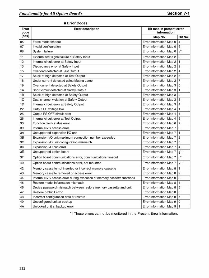
Functionality for All Option Board's Section 7-1
Error Codes
*1 These errors cannot be monitored in the Present Error Information.
Error code (hex)
Error description Bit map in present error information
Map No. Bit No.
05 Force mode timeout Error Information Map 0 4
07 Invalid configuration Error Information Map 0 6
08 System failure Error Information Map 0 7*1
11 External test signal failure at Safety Input Error Information Map 2 0
12 Internal circuit error at Safety Input Error Information Map 2 1
13 Discrepancy error at Safety Input Error Information Map 2 2
15 Overload detected at Test Output Error Information Map 2 4
17 Stuck-at-high detected at Test Output Error Information Map 2 6
18 Under current detected using Muting Lamp Error Information Map 2 7
19 Over current detected at Safety Output Error Information Map 3 0
1A Short circuit detected at Safety Output Error Information Map 3 1
1B Stuck-at-high detected at Safety Output Error Information Map 3 2
1C Dual channel violation at Safety Output Error Information Map 3 3
1D Internal circuit error at Safety Output Error Information Map 3 4
22 Output PS voltage low Error Information Map 4 1
25 Output PS OFF circuit error Error Information Map 4 4
26 Internal circuit error at Test Output Error Information Map 4 5
33 Function block status error Error Information Map 6 2
39 Internal NVS access error Error Information Map 7 0
3A Unsupported expansion I/O unit Error Information Map 7 1
3B Expansion I/O unit maximum connection number exceeded Error Information Map 7 2
3C Expansion I/O unit configuration mismatch Error Information Map 7 3
3D Expansion I/O bus error Error Information Map 7 4
3E Unsupported option board Error Information Map 7 5*1
3F Option board communications error, communications timeout Error Information Map 7 6*1
40 Option board communications error, not mounted Error Information Map 7 7*1
42 Memory cassette not inserted or incorrect memory cassette Error Information Map 8 1
43 Memory cassette removed or access error Error Information Map 8 2
44 Internal NVS access error during execution of memory cassette functions Error Information Map 8 3
45 Restore model information mismatch Error Information Map 8 4
46 Device password mismatch between restore memory cassette and unit Error Information Map 8 5
47 Restore prohibit error Error Information Map 8 6
48 Incorrect configuration data at restore Error Information Map 8 7
49 Unconfigured unit at backup Error Information Map 9 0
4A Unlocked unit at backup error Error Information Map 9 1
112

Functionality for All Option Board's Section 7-1
This section provides examples of values for present errors and the error logwhen the following errors occur.
Operation Log
This is a log of recorded operations. The operation details are given using thefollowing operation codes.
Sequence of occurrence
Error description Unit Conduction Time at error
Error status
1 Unsupported Option Board 0 day, 0 hours, 6 minutes = 000006 hex (minutes)
Cleared
2 Safety Input terminal error detected in dual-channel monitoring
100 days, 12 hours, 12 min-utes = 02355C hex (minutes)
Error occurred
3 Output power supply voltage error
100 days, 12 hours, 18 min-utes = 023562 hex (minutes)
Error occurred
Present Error Error Log
Value Error code Value
+0 Error Information Map 0 00 hex +0 Record 1 Unit Con-duction Time at error
22 hex
+1 Error Information Map 1 00 hex +1 02 hex
+2 Error Information Map 2 04 hex +2 35 hex
+3 Error Information Map 3 00 hex +3 62 hex
+4 Error Information Map 4 02 hex +4 Record 2 Error code 13 hex
+5 Error Information Map 5 00 hex +5 Unit Con-duction Time at error
02 hex
+6 Error Information Map 6 00 hex +6 35 hex
+7 Error Information Map 7 00 hex +7 5C hex
+8 Error Information Map 8 00 hex +8 Record 3 Error code 3E hex
+9 Error Information Map 9 00 hex +9 Unit Con-duction Time at error
00 hex
+10 Error Information Map 10 00 hex +10 00 hex
+11 Error Information Map 11 00 hex +11 06 hex
+12 Record 4 and higher
00 hex
--- 00 hex
+39 00 hex
Bit 7 Bit 6 Bit 5 Bit 4 Bit 3 Bit 2 Bit 1 Bit 0
+0 Operation record 1 (most recent) operation code
+1 Operation record 1 (most recent) Unit Conduction Time third byte at operation
+2 Operation record 1 (most recent) Unit Conduction Time second byte at operation
+3 Operation record 1 (most recent) Unit Conduction Time first byte at operation
--- ---
+36 Operation record 10 (oldest) operation code
+37 Operation record 10 (oldest) Unit Conduction Time third byte at operation
+38 Operation record 10 (oldest) Unit Conduction Time second byte at operation
+39 Operation record 10 (oldest) Unit Conduction Time first byte at operation
113

Functionality for All Option Board's Section 7-1
Operation Codes
Note Refer to 7-2 RS-232C Serial Communications and 7-3 Ethernet Communica-tions for examples of storing data to the memory of a Standard PLC.
Operation code (hex)
Operation description
01 Power ON or emulating cycling power
02 Out of box reset
04 Download
05 Lock/Unlock
06 Change Mode
07 Start/stop of force mode
08 Change device password
09 Clear error log
0A Backup to Memory Cassette
0B Restore from Memory Cassette
114
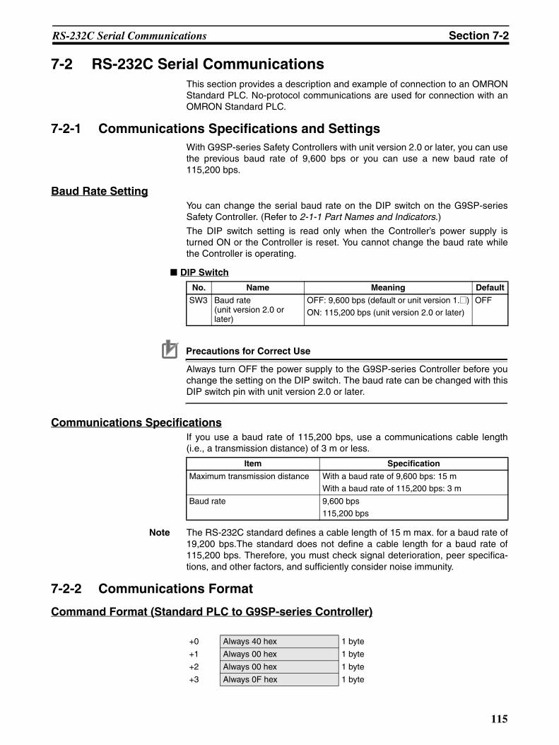
RS-232C Serial Communications Section 7-2
7-2 RS-232C Serial CommunicationsThis section provides a description and example of connection to an OMRONStandard PLC. No-protocol communications are used for connection with anOMRON Standard PLC.
7-2-1 Communications Specifications and SettingsWith G9SP-series Safety Controllers with unit version 2.0 or later, you can usethe previous baud rate of 9,600 bps or you can use a new baud rate of115,200 bps.
Baud Rate SettingYou can change the serial baud rate on the DIP switch on the G9SP-seriesSafety Controller. (Refer to 2-1-1 Part Names and Indicators.)
The DIP switch setting is read only when the Controller’s power supply isturned ON or the Controller is reset. You cannot change the baud rate whilethe Controller is operating.
DIP Switch
Precautions for Correct Use
Always turn OFF the power supply to the G9SP-series Controller before youchange the setting on the DIP switch. The baud rate can be changed with thisDIP switch pin with unit version 2.0 or later.
Communications SpecificationsIf you use a baud rate of 115,200 bps, use a communications cable length(i.e., a transmission distance) of 3 m or less.
Note The RS-232C standard defines a cable length of 15 m max. for a baud rate of19,200 bps.The standard does not define a cable length for a baud rate of115,200 bps. Therefore, you must check signal deterioration, peer specifica-tions, and other factors, and sufficiently consider noise immunity.
7-2-2 Communications Format
Command Format (Standard PLC to G9SP-series Controller)
No. Name Meaning Default
SW3 Baud rate (unit version 2.0 or later)
OFF: 9,600 bps (default or unit version 1.@)
ON: 115,200 bps (unit version 2.0 or later)
OFF
Item Specification
Maximum transmission distance With a baud rate of 9,600 bps: 15 mWith a baud rate of 115,200 bps: 3 m
Baud rate 9,600 bps
115,200 bps
+0 Always 40 hex 1 byte
+1 Always 00 hex 1 byte
+2 Always 00 hex 1 byte
+3 Always 0F hex 1 byte
115

RS-232C Serial Communications Section 7-2
Response Format (G9SP-series Controller to Standard PLC)
+4 Always 4B hex 1 byte
+5 Always 03 hex 1 byte
+6 Always 4D hex 1 byte
+7 Always 00 hex 1 byte
+8 Always 01 hex 1 byte
+9 Data 6 bytes
+15 Checksum (H) 2 bytes
+16 Checksum (L)
+17 Always 2A hex 1 byte
+18 Always 0D hex 1 byte
Parameter Description
Data Refer to Reception Data (Standard PLC to G9SP-series Con-troller) in 7-1-3 Transmission/Reception Data.
Checksum Checksum for bytes +0 to +14.
+0 Always 40 hex 1 byte
+1 Response length (HL): Always 00 hex.
1 byte
+2 Response length (LH): Always 00 hex.
1 byte
+3 Response length (LL) 1 byte
+4 End code (H) 2 bytes
+5 End code (L)
+6 Service code 1 byte
+7 Data 188 bytes
+195 Checksum (H) 2 bytes
+196 Checksum (L)
+197 Always 2A hex 1 byte
+198 Always 0D hex 1 byte
Parameter Description
Response length (LL) Normal response: C3 hex
Error response: 09 hex
Incorrect command format: 06 hex
End code Correct command format: 0000 hexIncorrect command format, (there will be no service code or data): Not 0000 hex
Service code Normal response: CB hex
Error response: 94 hex
Data Normal response: Refer to Transmission Data (G9SP-series Controller to Standard PLC) in 7-1-3 Transmission/Reception Data
Error response: Two bytes of reserved data
Checksum Checksum for bytes +0 to +194.
116

RS-232C Serial Communications Section 7-2
7-2-3 Application Example
System ConfigurationThis section uses the following example to describe how to access a G9SP-series Controller by performing serial communications through a RS-232CSerial Communications Board (CP1W-CIF01) from a Standard PLC.
Note This example uses the following OMRON Standard PLC.
G9SP-series Controller SettingsSettings are not required. Make the communications settings in the OMRONStandard PLC to match the serial communications specifications of theG9SP-series Controller.
Product Model/version
CPU Unit (Standard PLC) CP1E-N40DR-A
Support Software (for setup and creating ladder programs)
CX-Programmer Ver. 9.10
CP1E-series PLC
RS-232 port
G9SP-series Controller
No-protocol
OMRON Standard PLC (See note.)
CP1W-CIF01 Option Board
117

RS-232C Serial Communications Section 7-2
OMRON PLC SettingsSet serial port 1 as given below in the PLC Setup using the CX-Programmer.
Communications CableUse the following cable connections to connect to an OMRON CP1E-seriesPLC as a Standard PLC.
Parameter Description Set value for this example
Baud rate Serial port baud rate setting 9600, 8, 1, E
Mode Communications protocol RS-232C (no-protocol)
Start code Send/receive data start code 0x0040
End code Send/receive data end code Reception bytes: 198
FG 1 1 FG
SD 2 2 SD
RD 3 3 RD
RS 4 4 RS
CS 5 5 CS
5V 6 6 5V
DR 7 7 DR
ER 8 8 ER
SG 9 9 SG
G9SP-series RS-232C Serial Option Board (CP1W-CIF01)
Connector type Signal Pin
D-sub 9-pin male
Connector typePin Signal
D-sub 9-pin male
RS-232C port on CP1E-series PLC
118

RS-232C Serial Communications Section 7-2
Sample Ladder Programming for OMRON PLCThis section provides an example of programming to monitor Safety Input ter-minal data of a G9SP-series Controller from an OMRON Standard PLC.
RS-232C Serial Communications SequenceThe G9SP-series Controller returns a response to the command sent from theStandard PLC.
Standard PLC G9SP-series Controller
Sent command
Reception responseReceive processing after 300 ms
Send processing
Receive processing
Send processingSent command
Reception response
Receive processing
Send processing
Send/receive processing
Send/receive processingReceive processing after 300 ms
Initialization
119
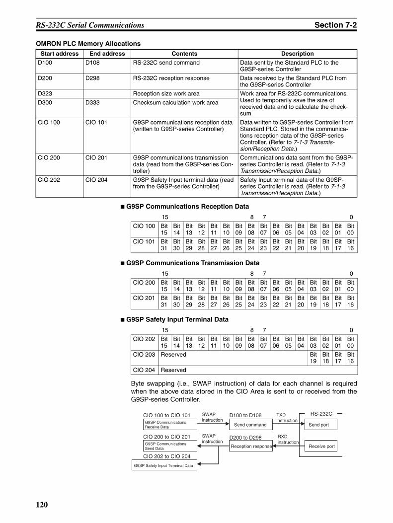
RS-232C Serial Communications Section 7-2
OMRON PLC Memory Allocations
G9SP Communications Reception Data
G9SP Communications Transmission Data
G9SP Safety Input Terminal Data
Byte swapping (i.e., SWAP instruction) of data for each channel is requiredwhen the above data stored in the CIO Area is sent to or received from theG9SP-series Controller.
Start address End address Contents Description
D100 D108 RS-232C send command Data sent by the Standard PLC to the G9SP-series Controller
D200 D298 RS-232C reception response Data received by the Standard PLC from the G9SP-series Controller
D323 Reception size work area Work area for RS-232C communications.Used to temporarily save the size of received data and to calculate the check-sum
D300 D333 Checksum calculation work area
CIO 100 CIO 101 G9SP communications reception data (written to G9SP-series Controller)
Data written to G9SP-series Controller from Standard PLC. Stored in the communica-tions reception data of the G9SP-series Controller. (Refer to 7-1-3 Transmis-sion/Reception Data.)
CIO 200 CIO 201 G9SP communications transmission data (read from the G9SP-series Con-troller)
Communications data sent from the G9SP-series Controller is read. (Refer to 7-1-3 Transmission/Reception Data.)
CIO 202 CIO 204 G9SP Safety Input terminal data (read from the G9SP-series Controller)
Safety Input terminal data of the G9SP-series Controller is read. (Refer to 7-1-3 Transmission/Reception Data.)
15 8 7 0
CIO 100 Bit 15
Bit 14
Bit 13
Bit 12
Bit 11
Bit 10
Bit 09
Bit 08
Bit 07
Bit 06
Bit 05
Bit 04
Bit 03
Bit 02
Bit 01
Bit 00
CIO 101 Bit 31
Bit 30
Bit 29
Bit 28
Bit 27
Bit 26
Bit 25
Bit 24
Bit 23
Bit 22
Bit 21
Bit 20
Bit 19
Bit 18
Bit 17
Bit 16
15 8 7 0
CIO 200 Bit 15
Bit 14
Bit 13
Bit 12
Bit 11
Bit 10
Bit 09
Bit 08
Bit 07
Bit 06
Bit 05
Bit 04
Bit 03
Bit 02
Bit 01
Bit 00
CIO 201 Bit 31
Bit 30
Bit 29
Bit 28
Bit 27
Bit 26
Bit 25
Bit 24
Bit 23
Bit 22
Bit 21
Bit 20
Bit 19
Bit 18
Bit 17
Bit 16
15 8 7 0
CIO 202 Bit 15
Bit 14
Bit 13
Bit 12
Bit 11
Bit 10
Bit 09
Bit 08
Bit 07
Bit 06
Bit 05
Bit 04
Bit 03
Bit 02
Bit 01
Bit 00
CIO 203 Reserved Bit 19
Bit 18
Bit 17
Bit 16
CIO 204 Reserved
Send port
Receive port
RS-232C
Send command
Reception response
G9SP Communications Receive Data
G9SP Communications Send Data
G9SP Safety Input Terminal Data
TXD instruction
RXD instruction
D100 to D108
D200 to D298
CIO 100 to CIO 101
CIO 200 to CIO 201
CIO 202 to CIO 204
SWAP instruction
SWAP instruction
120

RS-232C Serial Communications Section 7-2
Sample Ladder Programming
From Initial Settings to Cyclic Send/Receive
(1)
(2)
(3)(4) (5)
(7)
(6)
(8)
(9)
(10)
(11)
(12)
Reception processing
Send processing
Initial settings
121
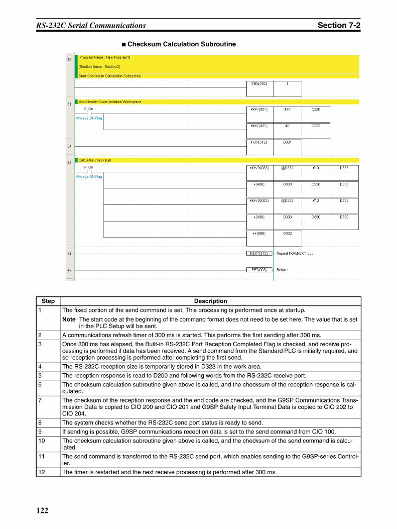
RS-232C Serial Communications Section 7-2
Checksum Calculation Subroutine
Step Description
1 The fixed portion of the send command is set. This processing is performed once at startup.
Note The start code at the beginning of the command format does not need to be set here. The value that is set in the PLC Setup will be sent.
2 A communications refresh timer of 300 ms is started. This performs the first sending after 300 ms.
3 Once 300 ms has elapsed, the Built-in RS-232C Port Reception Completed Flag is checked, and receive pro-cessing is performed if data has been received. A send command from the Standard PLC is initially required, and so reception processing is performed after completing the first send.
4 The RS-232C reception size is temporarily stored in D323 in the work area.
5 The reception response is read to D200 and following words from the RS-232C receive port.
6 The checksum calculation subroutine given above is called, and the checksum of the reception response is cal-culated.
7 The checksum of the reception response and the end code are checked, and the G9SP Communications Trans-mission Data is copied to CIO 200 and CIO 201 and G9SP Safety Input Terminal Data is copied to CIO 202 to CIO 204.
8 The system checks whether the RS-232C send port status is ready to send.
9 If sending is possible, G9SP communications reception data is set to the send command from CIO 100.
10 The checksum calculation subroutine given above is called, and the checksum of the send command is calcu-lated.
11 The send command is transferred to the RS-232C send port, which enables sending to the G9SP-series Control-ler.
12 The timer is restarted and the next receive processing is performed after 300 ms.
122
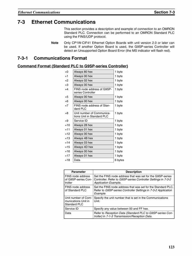
Ethernet Communications Section 7-3
7-3 Ethernet CommunicationsThis section provides a description and example of connection to an OMRONStandard PLC. Connection can be performed to an OMRON Standard PLCusing the FINS/UDP protocol.
Note Only CP1W-CIF41 Ethernet Option Boards with unit version 2.0 or later canbe used. If another Option Board is used, the G9SP-series Controller willdetect an Unsupported Option Board Error (the MS indicator will flash red).
7-3-1 Communications Format
Command Format (Standard PLC to G9SP-series Controller)+0 Always 80 hex 1 byte
+1 Always 00 hex 1 byte
+2 Always 02 hex 1 byte
+3 Always 00 hex 1 byte
+4 FINS node address of G9SP-series Controller
1 byte
+5 Always 00 hex 1 byte
+6 Always 00 hex 1 byte
+7 FINS node address of Stan-dard PLC
1 byte
+8 Unit number of Communica-tions Unit in Standard PLC
1 byte
+9 Service ID 1 byte
+10 Always 28 hex 1 byte
+11 Always 01 hex 1 byte
+12 Always 00 hex 1 byte
+13 Always 4B hex 1 byte
+14 Always 03 hex 1 byte
+15 Always 4D hex 1 byte
+16 Always 00 hex 1 byte
+17 Always 01 hex 1 byte
+18 Data 6 bytes
Parameter Description
FINS node address of G9SP-series Con-troller
Set the FINS node address that was set for the G9SP-series Controller. Refer to G9SP-series Controller Settings in 7-3-2 Application Example.
FINS node address of Standard PLC
Set the FINS node address that was set for the Standard PLC.Refer to G9SP-series Controller Settings in 7-3-2 Application Example.
Unit number of Com-munications Unit in Standard PLC
Specify the unit number that is set in the Communications Unit.
Service ID Specify any value between 00 and FF hex.
Data Refer to Reception Data (Standard PLC to G9SP-series Con-troller) in 7-1-3 Transmission/Reception Data.
123

Ethernet Communications Section 7-3
Response Format (G9SP-series Controller to Standard PLC)+0 Always C0 hex 1 byte
+1 Always 00 hex 1 byte
+2 Always 02 hex 1 byte
+3 Always 00 hex 1 byte
+4 FINS node address of Stan-dard PLC
1 byte
+5 Unit number of Communica-tions Unit in Standard PLC
1 byte
+6 Always 00 hex 1 byte
+7 FINS node address of G9SP-series Controller
1 byte
+8 Always 00 hex 1 byte
+9 Service ID 1 byte
+10 Always 28 hex 1 byte
+11 Always 01 hex 1 byte
+12 End code (H) 2 bytes
+13 End code (L)
+14 Number of receive bytes (H) 2 bytes
+15 Number of receive bytes (L)
+16 Always 00 hex 1 byte
+17 Service code 1 byte
+18 Data 188 bytes
Parameter Description
FINS node address of Stan-dard PLC
The FINS node address that was set for the Standard PLC is stored.
FINS node address of G9SP-series Controller
The FINS node address that was set for the G9SP-series Control-ler is stored.
Unit number of Communications Unit in Standard PLC
Set the unit number that is set in the Communications Unit.
Service ID The service ID that was set in the command format is stored.
End code Normal command format (including an error response): 0000 hexError command format, in which case there is no subsequent data: Not 0000 hex
Number of receive bytes
Normal response: 00BE hexError response: 0004 hex
Service code Normal response: CB hexError response: 94 hex
Data Normal response: Refer to Transmission Data (G9SP-series Con-troller to Standard PLC) in 7-1-3 Transmission/Reception DataError response: Two bytes of reserved data
124

Ethernet Communications Section 7-3
7-3-2 Application Example
System ConfigurationThis section uses the following example to describe how to access the G9SP-series Controller from a Standard PLC by performing Ethernet communica-tions through an Ethernet Communications Board (CP1W-CIF41).
Note This example uses the following OMRON Standard PLC.
G9SP-series Controller SettingsMake the settings for TCP/IP in the system settings of the G9SP Configurator.These settings are set in the G9SP-series Controller and Ethernet OptionBoard when the configuration data is downloaded.
Product Model/version
CPU Unit (Standard PLC) CJ1M-CPU11
Ethernet Communications Unit CJ1W-ETN21
Switching hub W4S1-05B
Support Software (for setup and creating ladder programs)
CX-Programmer Ver. 9.10
CJ1M CJ1W-ETN21 Ethernet Unit
G9SP-series Controller
FINS/UDP
OMRON Standard PLC (See note.)
CP1W-CIF41 Option Board
192.168.250.1
192.168.250.2
Switching hub
Parameter Description Set value for this example
IP address IP address of Ethernet Option Board. Default value: 192.168.250.1
192.168.250.2
Subnet mask Subnet mask of Ethernet Option Board. Default value: 255.255.255.0
No change is required.
Default gateway Set the IP address of the default gate-way. Default value: 0.0.0.0 (IP routing not supported)
No change is required.
FINS node address Set the FINS node address of the Ethernet Option Board. If automatic setting is specified, a value that matches the rightmost byte of the IP address is stored.Default value: Automatic (matching the rightmost byte of the IP address)
Setting range: 1 to 254
No change is required.
125
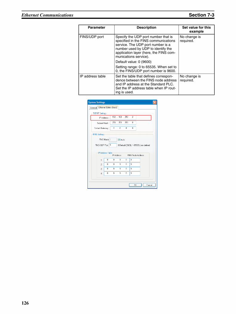
Ethernet Communications Section 7-3
FINS/UDP port Specify the UDP port number that is specified in the FINS communications service. The UDP port number is a number used by UDP to identify the application layer (here, the FINS com-munications service).
Default value: 0 (9600)
Setting range: 0 to 65535. When set to 0, the FINS/UDP port number is 9600.
No change is required.
IP address table Set the table that defines correspon-dence between the FINS node address and IP address at the Standard PLC. Set the IP address table when IP rout-ing is used.
No change is required.
Parameter Description Set value for this example
126

Ethernet Communications Section 7-3
OMRON PLC SettingsSet the Ethernet port as shown below in the PLC Setup using the CX-Pro-grammer.
Sample Ladder Programming for OMRON PLCThis section provides an example of programming to monitor Safety Input ter-minal data of a G9SP-series Controller from an OMRON Standard PLC.
Ethernet Communications SequenceThe G9SP-series Controller returns a response to the command sent from theStandard PLC.
Parameter Description Set value for this example
IP address IP address of the CJ1W-ETN21 192.168.250.1
Subnet mask Subnet mask of the CJ1W-ETN21 255.255.255.0
Standard PLC G9SP-series Controller
Sent command
Reception response
Send processing
Receive processing
Send processingSent command
Reception response
Receive processing
Send processing
Send/receive processing
Send/receive processing
Initialization
127

Ethernet Communications Section 7-3
OMRON PLC Memory Allocations
G9SP Communications Reception Data
G9SP Communications Transmission Data
G9SP Safety Input Terminal Data
Byte swapping (i.e., SWAP instruction) of data for each channel is requiredwhen the above data stored in the CIO Area is sent to or received from theG9SP-series Controller.
Start address End address Contents Description
D100 D108 Ethernet send command Data sent by the Standard PLC to the G9SP-series Controller
D200 D298 Ethernet reception response Data received by the Standard PLC from the G9SP-series Controller
D300 D305 CMND instruction control data Control data for the CMND instruction is stored.
CIO 100 CIO 101 G9SP communications reception data (written to G9SP-series Controller)
Data written to G9SP-series Controller from Standard PLC. Stored in the communica-tions reception data of the G9SP-series Controller. (Refer to 7-1-3 Transmis-sion/Reception Data.)
CIO 200 CIO 201 G9SP communications transmission data (read from the G9SP-series Con-troller)
Communications data sent from the G9SP-series Controller is read. (Refer to 7-1-3 Transmission/Reception Data.)
CIO 202 CIO 204 G9SP Safety Input terminal data (read from the G9SP-series Controller)
Safety Input terminal data of the G9SP-series Controller is read. (Refer to 7-1-3 Transmission/Reception Data.)
15 8 7 0
CIO 100 Bit 15
Bit 14
Bit 13
Bit 12
Bit 11
Bit 10
Bit 09
Bit 08
Bit 07
Bit 06
Bit 05
Bit 04
Bit 03
Bit 02
Bit 01
Bit 00
CIO 101 Bit 31
Bit 30
Bit 29
Bit 28
Bit 27
Bit 26
Bit 25
Bit 24
Bit 23
Bit 22
Bit 21
Bit 20
Bit 19
Bit 18
Bit 17
Bit 16
15 8 7 0
CIO 200 Bit 15
Bit 14
Bit 13
Bit 12
Bit 11
Bit 10
Bit 09
Bit 08
Bit 07
Bit 06
Bit 05
Bit 04
Bit 03
Bit 02
Bit 01
Bit 00
CIO 201 Bit 31
Bit 30
Bit 29
Bit 28
Bit 27
Bit 26
Bit 25
Bit 24
Bit 23
Bit 22
Bit 21
Bit 20
Bit 19
Bit 18
Bit 17
Bit 16
15 8 7 0
CIO 202 Bit 15
Bit 14
Bit 13
Bit 12
Bit 11
Bit 10
Bit 09
Bit 08
Bit 07
Bit 06
Bit 05
Bit 04
Bit 03
Bit 02
Bit 01
Bit 00
CIO 203 Reserved Bit 19
Bit 18
Bit 17
Bit 16
CIO 204 Reserved
Send port
Receive port
Ethernet
Sent command
Reception response
G9SP Communications Receive Data
G9SP Communications Send Data
G9SP Safety Input Terminal Data
CMND instruction
D100 to D108
D200 to D298
CIO 100 to CIO 101
CIO 200 to CIO 201
CIO 202 to CIO 204
SWAP instruction
SWAP instruction
128

Ethernet Communications Section 7-3
Sample Ladder Programming
Step Description
1 The fixed portion of the send command is set. This processing is performed once at startup.
2 Set the control data of the CMND instruction.
3 Clear the receive area in preparation for the first reception.
4 Once the data has been stored in the cleared receive area, check the size, and then start receive processing.
5 From the response, copy the G9SP Communications Transmission Data to CIO 200 and CIO 201 and the G9SP Safety Input Terminal Data to CIO 202 to CIO 204.
6 Once receive processing has been completed, set G9SP Communications Reception Data to the send com-mand from CIO 100.
7 Clear the receive area in preparation for the next reception.
8 The send command is sent to the Ethernet send port, which enables sending to the G9SP-series Controller.
(1)
(3)
(4)
(6)
(5) Reception processing
Send processing
Initialization
(2)
(7) (8)
129

Ethernet Communications Section 7-3
130

Software Design
SECTION 8Connecting Online and Downloading to the G9SP-series
Controller
This section describes how to connect the G9SP-series Controller online to the computer and download the configurationdata to the G9SP-series Controller.
8-1 Overview . . . . . . . . . . . . . . . . . . . . . . . . . . . . . . . . . . . . . . . . . . . . . . . . . . . . . 132
8-2 Downloading Configuration Data to the G9SP-series Controller and Verification 133
8-2-1 Connecting Online . . . . . . . . . . . . . . . . . . . . . . . . . . . . . . . . . . . . . . 133
8-2-2 Downloading to G9SP-series Controller . . . . . . . . . . . . . . . . . . . . . 133
8-2-3 Verifying the Configuration Data . . . . . . . . . . . . . . . . . . . . . . . . . . . 134
8-3 Uploading Data from the G9SP-series Controller . . . . . . . . . . . . . . . . . . . . . 135
8-4 Resetting the G9SP-series Controller . . . . . . . . . . . . . . . . . . . . . . . . . . . . . . . 136
8-5 Setting a Device Password . . . . . . . . . . . . . . . . . . . . . . . . . . . . . . . . . . . . . . . 137
131

Overview Section 8-1
8-1 OverviewThe configuration data that was created in SECTION 6 Creating ConfigurationData is downloaded to the G9SP-series Controller. The G9SP-series Control-ler is then changed to RUN Mode so that the operation of the G9SP Systemcan be verified.
The G9SP Configurator is connected online to the G9SP-series Controller todownload the data, change to RUN Mode, and verify operation.
Basic Procedure to Prepare for OperationBasically, preparations for operation with the G9SP-series Controller are per-formed with the following procedure.
1. Connect the G9SP Configurator online to the G9SP-series Controller.
2. Download the configuration data to the G9SP-series Controller.
3. Verify the configuration data.
4. Change to RUN Mode. (Refer to SECTION 9 Operation and OperatingModes.)
5. Check operating status and debugging. (Refer to SECTION 10 CheckingOperating Status and Debugging.)
6. Perform safety validation testing (user testing). (Refer to SECTION 10Checking Operating Status and Debugging.)
7. Lock the configuration data. (Refer to SECTION 9 Operation and Operat-ing Modes.)
This section describes steps 1 to 3, as well as the following online operations.
Uploading Data from the G9SP-series Controller
The final configuration data can be read from the G9SP-series Controller.
Resetting
The G9SP-series Controller can be restarted or the configuration data can bedeleted and the G9SP-series Controller returned to the default status.
Setting a Device Password
A Device Password can be set to prevent unapproved access to the G9SP-series Controller, including changes to the configuration data and changingthe modes.
G9SP-series Controller
Download
UploadG9SP Configurator
132

Downloading Configuration Data to the G9SP-series Controller and Verification Section 8-2
8-2 Downloading Configuration Data to the G9SP-series Controller and Verification
This section provides the procedure to place the G9SP Configurator onlineand download configuration data to the G9SP-series Controller.
8-2-1 Connecting Online
ProcedureWhen an online connection is established, communications between theG9SP Configurator and G9SP-series Controller will start.
1,2,3... 1. Click the Connect Icon ( ).
2. If the icon changes as shown below, communications have been start-ed.
8-2-2 Downloading to G9SP-series Controller
ProcedureAfter the online connection has been established, there are two ways to down-load configuration data to the G9SP-series Controller, as shown below.
1,2,3... 1. Click the Download Icon ( ).
2. Input the Device Password when prompted. If a device password is not set,do not input anything.
3. If a display appears saying that the download was successful, the down-load was completed normally.
Precautions for Correct Use
The configuration data cannot be downloaded while a Memory Cassette isinserted in the G9SP-series Controller. If necessary, remove the MemoryCassette, restart the G9SP-series Controller, and then download the data.
133

Downloading Configuration Data to the G9SP-series Controller and Verification Section 8-2
8-2-3 Verifying the Configuration DataAfter the download has been completed, a verification is performed to checkthat the configuration data that was created has been correctly downloaded tothe G9SP-series Controller. If the verification confirms that the configuration iscorrect, a report created from data uploaded from the G9SP-series Controllerwill be displayed.
Verified configurations will be indicated by Verified displayed at the lower rightcenter on the G9SP Configurator.
Precautions for Safe Use
Be sure to use the report that is displayed after the verification has finished tocheck that the configuration that was created matches the configuration thatwas downloaded.
Verification Procedure
1,2,3... 1. Click the Verify Icon ( ).
2. A verification report will be created if a message appears saying that nodifferences were found in the parameters.
3. Check the contents of the report, and then click the Save Button.
4. A message will ask if it is OK to mark the device for a verified configuration.Click the Yes Button, and the icon will change to Verified.
Additional Information
• To continue by checking I/O wiring or operating status, refer to the followingsections.
Checking I/O wiring → 10-3 Debugging in Force Mode.
Checking operating status → 9-2 Changing the Operating Mode.
• After verifying project files for which safety validation testing (user testing)was performed, you can also lock the configuration data. Refer to 9-3 Con-figuration Lock and Automatic Operation for information on locking the con-figuration data.
134
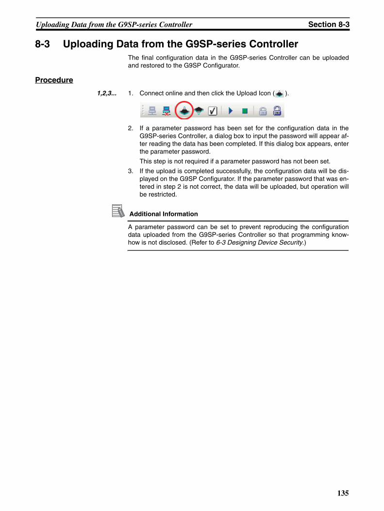
Uploading Data from the G9SP-series Controller Section 8-3
8-3 Uploading Data from the G9SP-series ControllerThe final configuration data in the G9SP-series Controller can be uploadedand restored to the G9SP Configurator.
Procedure
1,2,3... 1. Connect online and then click the Upload Icon ( ).
2. If a parameter password has been set for the configuration data in theG9SP-series Controller, a dialog box to input the password will appear af-ter reading the data has been completed. If this dialog box appears, enterthe parameter password.
This step is not required if a parameter password has not been set.
3. If the upload is completed successfully, the configuration data will be dis-played on the G9SP Configurator. If the parameter password that was en-tered in step 2 is not correct, the data will be uploaded, but operation willbe restricted.
Additional Information
A parameter password can be set to prevent reproducing the configurationdata uploaded from the G9SP-series Controller so that programming know-how is not disclosed. (Refer to 6-3 Designing Device Security.)
135
Resetting the G9SP-series Controller Section 8-4
8-4 Resetting the G9SP-series ControllerThe G9SP Configurator can reset the G9SP-series Controller in the followingtwo ways. A password is required to execute the reset.
Reset Types
The configuration data includes hardware settings, such as I/O terminal set-tings as well as the program and system settings.
The G9SP-series Controller stores this data in nonvolatile memory. Someinformation, however, cannot be changed once it is set without resetting theG9SP-series Controller. Select Return to the out-of-box configuration, andthen emulate cycling power to return the information to the default parametersettings.
Reset Type and Controller StatusDepending on the reset type and the G9SP-series Controller status, resettingmight not be possible. Refer to 9-3 Configuration Lock and Automatic Opera-tion for information on locking the configuration.
Procedure for Resetting
1,2,3... 1. Go online and select Reset from the Communication Menu.
2. In the Device Reset Window, input the reset type and the Device Pass-word.
3. If a display appears saying that the reset has been completed, the G9SP-series Controller has been reset.
Reset type Configuration data MS indicator Error log/operation log
Unit Conduction Time
Emulate cycling power Settings before the reset are retained.
Same as before reset. Log before the reset is retained.
Values before reset are retained.
Return to the out-of-box configuration, and then emulate cycling power. (Initialize all data.)
Initialization (Default) Flashing red and green. (Waiting for configuration.)
Log before the reset is retained.
Values before reset are retained.
Reset type G9SP-series Controller status
Configuration lock - LOCK indicator lit yellow.
Configuration lock - LOCK indicator flashing
yellow or not lit.
Emulate cycling power Able to reset Able to reset
Return to the out-of-box configuration, and then emulate cycling power
Unable to reset Able to reset
136

Setting a Device Password Section 8-5
8-5 Setting a Device PasswordThe G9SP-series Controller can record a Device Password in nonvolatilememory. The Device Password can be used to prevent unauthorized or unin-tentional access to the G9SP-series Controller from a person other than auser (i.e., a safety manager).
No Device Password is set by default; the user must register one. Use theG9SP Configurator to set or change the Device Password for the G9SP-seriesController.
Scope of Access ControlThe following operations require the user to enter a Device Password. TheG9SP-series Controller will not perform the following operations unless thepassword is correct.
• Downloading the configuration
• Locking or unlocking the configuration
• Executing the Controller's reset service
• Changing the operating mode
• Changing the password
Lost Device PasswordContact your OMRON representative if you lose the password that is set in theG9SP-series Controller. For details, refer to Appendix B Using the PasswordRecovery Tool.
Procedure for Setting Device Password
1,2,3... 1. Go online and select Change Device Password from the CommunicationMenu.
2. In the Change Password Window shown below, input the current passwordand the new password.
Additional Information
For details on the Device Password, refer to 6-3 Designing Device Security.
Input the same password again.
Input 6 to 16 characters.Blank when no password is set.
137

Setting a Device Password Section 8-5
138

Software Design
SECTION 9Operation and Operating Modes
This section describes how to switch the G9SP-series Controllers to RUN Mode.
9-1 G9SP-series Controller Operating Modes. . . . . . . . . . . . . . . . . . . . . . . . . . . . 140
9-2 Changing the Operating Mode . . . . . . . . . . . . . . . . . . . . . . . . . . . . . . . . . . . . 142
9-3 Configuration Lock and Automatic Operation . . . . . . . . . . . . . . . . . . . . . . . . 143
9-4 Changing the Configuration Data . . . . . . . . . . . . . . . . . . . . . . . . . . . . . . . . . . 145
9-5 Operation for Power Supply Interruptions . . . . . . . . . . . . . . . . . . . . . . . . . . . 146
9-5-1 Operation for Voltage Drop . . . . . . . . . . . . . . . . . . . . . . . . . . . . . . . 146
139
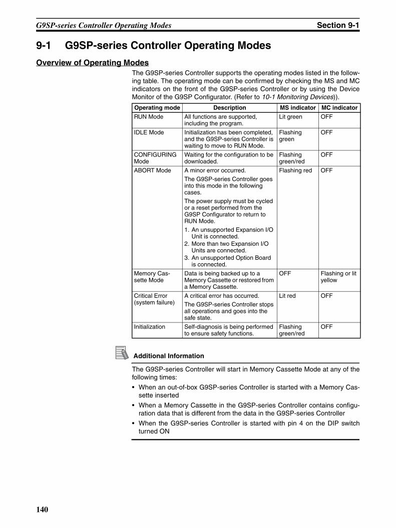
G9SP-series Controller Operating Modes Section 9-1
9-1 G9SP-series Controller Operating Modes
Overview of Operating ModesThe G9SP-series Controller supports the operating modes listed in the follow-ing table. The operating mode can be confirmed by checking the MS and MCindicators on the front of the G9SP-series Controller or by using the DeviceMonitor of the G9SP Configurator. (Refer to 10-1 Monitoring Devices)).
Additional Information
The G9SP-series Controller will start in Memory Cassette Mode at any of thefollowing times:
• When an out-of-box G9SP-series Controller is started with a Memory Cas-sette inserted
• When a Memory Cassette in the G9SP-series Controller contains configu-ration data that is different from the data in the G9SP-series Controller
• When the G9SP-series Controller is started with pin 4 on the DIP switchturned ON
Operating mode Description MS indicator MC indicator
RUN Mode All functions are supported, including the program.
Lit green OFF
IDLE Mode Initialization has been completed, and the G9SP-series Controller is waiting to move to RUN Mode.
Flashing green
OFF
CONFIGURING Mode
Waiting for the configuration to be downloaded.
Flashing green/red
OFF
ABORT Mode A minor error occurred.
The G9SP-series Controller goes into this mode in the following cases.
The power supply must be cycled or a reset performed from the G9SP Configurator to return to RUN Mode.1. An unsupported Expansion I/O
Unit is connected.2. More than two Expansion I/O
Units are connected.3. An unsupported Option Board
is connected.
Flashing red OFF
Memory Cas-sette Mode
Data is being backed up to a Memory Cassette or restored from a Memory Cassette.
OFF Flashing or lit yellow
Critical Error (system failure)
A critical error has occurred.
The G9SP-series Controller stops all operations and goes into the safe state.
Lit red OFF
Initialization Self-diagnosis is being performed to ensure safety functions.
Flashing green/red
OFF
140

G9SP-series Controller Operating Modes Section 9-1
Functions Supported in Each Operating ModeThe following table shows the status of each Controller operating mode, andthe operations that are supported from the G9SP Configurator in each mode.
Note (1) The safe state means the following:
• Safety Output terminals are OFF.
(2) Force-setting and force-resetting can be performed only if the configura-tion is unlocked.
(3) The configuration can be downloaded only when a Memory Cassette isnot inserted.
Operating mode
Safety functions Standard functions
Operations from G9SP Configurator
RUN Mode Exe-cuted
I/O re-freshed
Sup-ported
Sup-ported
Sup-ported (See note 3.)
Sup-ported
Sup-ported
Sup-ported
Sup-ported
Sup-ported (See note 2.)
IDLE Mode Stopped
CONFIGUR-ING Mode
Safe state
Not sup-ported
Not sup-ported
ABORT Mode Not sup-ported
Sup-ported/Not sup-ported
Memory Cas-sette Mode
Not sup-ported
Not sup-ported
Critical Error (system failure)
Stopped Stopped Not sup-ported
Not sup-ported
Not sup-ported
Not sup-ported
Initialization
Pro
gra
m e
xecu
tio
n
Lo
gic
al I/
O c
on
tro
l
US
B c
om
mu
nic
atio
ns
Op
tio
n B
oar
d
com
mu
nic
atio
ns
Co
nfi
gu
rati
on
d
own
load
Co
nfi
gu
rati
on
lock
/ u
nlo
ck
Res
et
Dev
ice
pas
swo
rd
chan
ges
On
line
mo
nit
ori
ng
Fo
rce-
sett
ing
/re
sett
ing
141

Changing the Operating Mode Section 9-2
9-2 Changing the Operating Mode
Moving between Operating ModesThe following diagram shows mode changes after initialization has been com-pleted at startup.
The following diagram shows mode changes for RUN Mode, IDLE Mode, andCONFIGURING Mode.
Procedure for Changing ModesAfter the configuration data for the G9SP-series Controller has been down-loaded, start program execution by changing the mode using the G9SP Con-figurator.
1,2,3... 1. Go online and then click the Mode Change (RUN) Icon.
To return to IDLE Mode, click the Mode Change (IDLE) Icon,
2. Enter the Device Password when prompted.
3. When the mode has been changed, a message saying that the mode hasbeen changed successfully will be displayed. Confirm that the MS indicatoron the G9SP-series Controller is lit green.
INITIALIZATION
RUN Mode
RUN and unlocked
RUN and locked
IDLE and unlocked
IDLE and locked
CONFIGURINGMode
No valid configuration
IDLE Mode
Power ON
Configuration is valid and configuration is unlocked.
Lock: Configuration locked
Unlocked: Configuration unlocked
Power interrupted when configuration is valid, configuration is locked, and the mode is IDLE.
Power interrupted when configuration is valid,
configuration is locked, and the mode is RUN.
Note:
IDLE and unlocked
RUN Mode
IDLE and locked
RUN and unlocked
RUN and locked
IDLE Mode
Mode change (RUN)
Mode change (IDLE)
Mode change (RUN)
Mode change (IDLE)
Download
Download
142

Configuration Lock and Automatic Operation Section 9-3
9-3 Configuration Lock and Automatic Operation
Configuration LockThe configuration data that was saved in the G9SP-series Controller can belocked to protect the data after it has been downloaded, verified, and safetyvalidation testing (user testing) has been performed. Once the configuration islocked, the configuration cannot be changed until it is unlocked.
The following occurs when the configuration lock is set.
• The LOCK indicator on the front face of the G9SP-series Controller willlight yellow when the data is locked. (When unlocked, the indicator willflash yellow.)
• On the G9SP Configurator, the Verified [Locked] is displayed.
* After the data has been locked, the lock icon will turn yellow if the configura-tion is changed.
Configuration Lock Procedure
1,2,3... 1. Go online and then click the Configuration Lock Icon.
2. Input the Device Password when prompted. If a device password is not set,do not input anything.
3. The LOCK indicator on the front of the G9SP-series Controller will light yel-low if the configuration is locked successfully. A mark that indicates thelocked status will be displayed on the G9SP Configurator.
Precautions for Correct Use
The configuration data must be verified before it can be locked. Confirm that“Verified” is displayed on the G9SP Configurator.
Starting Operating Mode Using Automatic OperationTo protect the user, the G9SP-series Controller will always start in IDLE Modeif safety validation testing (user testing) has not been completed.
After safety validation testing has been completed, the G9SP-series Control-ler will start in RUN Mode if the following conditions are met. In that case, itwill not be necessary to change the mode from the G9SP Configurator.
• The configuration is locked.
• The power was turned OFF after changing to RUN Mode.
Precautions for Correct Use
Even if the configuration is locked, the G9SP-series Controller will not start inRUN Mode the next time if the power is turned OFF while in IDLE Mode. Besure to turn OFF the power while in RUN Mode.
143

Configuration Lock and Automatic Operation Section 9-3
Unlocking the Configuration
1,2,3... 1. Go online and then click the Configuration Unlock Icon.
2. Input the Device Password when prompted. If a device password is not set,do not input anything.
3. The LOCK indicator on the front of the G9SP-series Controller will light yel-low if the configuration is locked successfully. A mark that indicates the un-locked status will be displayed on the G9SP Configurator.
144

Changing the Configuration Data Section 9-4
9-4 Changing the Configuration DataThis section describes how to change the G9SP-series Controller configura-tion data after the configuration has been downloaded or after operation hasbeen started.
Procedure for Changing the ConfigurationTo change the G9SP-series Controller configuration data, first carefully checksystem safety and then unlock the configuration data. The procedure forchanging the configuration is as follows:
1,2,3... 1. Check the system safety.
2. Change the G9SP-series Controller's operating mode from RUN to IDLE.
3. Unlock the G9SP-series Controller configuration data.
4. Download the configuration data to the G9SP-series Controller.
5. Verify the configuration data.
6. Change the G9SP-series Controller's operating mode from IDLE to RUN.
7. Perform safety validation testing (user testing).
8. Lock the configuration data.
Precautions for Safe Use
After changing the G9SP-series Controller's configuration data, confirm thatthe safety functions are functioning properly before starting operation.
145
Operation for Power Supply Interruptions Section 9-5
9-5 Operation for Power Supply Interruptions
9-5-1 Operation for Voltage DropThe G9SP-series Controller monitors the power supply voltage to ensure safeoperation. If a voltage over the upper limit or under the lower limit is detected,the following operations will be performed.
Operation for Voltage Errors in Internal Circuit Power SupplyIf a voltage error occurs in the internal circuit power supply, the G9SP-seriesController will stop operation and turn OFF the outputs. The G9SP-seriesController will restart operation when the power supply voltage returns to nor-mal.
Operation for Voltage Errors in Output Circuit Power SupplyIf an error occurs in the output power supply, the G9SP-series Controller willcontinue operation, but it will turn OFF the outputs. The OUT PWR indicatoron the G9SP-series Controller or the I/O power supply monitor can be used tosee if the output power supply voltage is being supplied correctly.
Checking Method 1: Using the G9SP Configurator for MonitoringRefer to 10-1-3 Error Log and 10-1-4 Operation Log.
Checking Method 2: Using the Safety Output Power Supply Error Flag via Option Board Communications
Refer to SECTION 7 Communications with a Standard PLC Using an OptionBoard.
Checking Method 3: Using the Safety Output Power Supply Error Flag (I/O Tag) in the ProgramRefer to the G9SP-N@@@ Safety Controller Instructions Reference Manual(Cat. No. Z923).
146

Startup and Debugging
SECTION 10Checking Operating Status and Debugging
This section describes how to use a computer to monitor the G9SP-series Controller and how to debug the program by usingForce Mode.
10-1 Monitoring Devices. . . . . . . . . . . . . . . . . . . . . . . . . . . . . . . . . . . . . . . . . . . . . 148
10-1-1 Device Monitor . . . . . . . . . . . . . . . . . . . . . . . . . . . . . . . . . . . . . . . . . 148
10-1-2 Monitoring Status . . . . . . . . . . . . . . . . . . . . . . . . . . . . . . . . . . . . . . . 149
10-1-3 Error Log . . . . . . . . . . . . . . . . . . . . . . . . . . . . . . . . . . . . . . . . . . . . . 150
10-1-4 Operation Log. . . . . . . . . . . . . . . . . . . . . . . . . . . . . . . . . . . . . . . . . . 151
10-2 Monitoring Programs . . . . . . . . . . . . . . . . . . . . . . . . . . . . . . . . . . . . . . . . . . . 152
10-2-1 Program Monitor . . . . . . . . . . . . . . . . . . . . . . . . . . . . . . . . . . . . . . . 152
10-2-2 Watch Window . . . . . . . . . . . . . . . . . . . . . . . . . . . . . . . . . . . . . . . . . 153
10-3 Debugging in Force Mode. . . . . . . . . . . . . . . . . . . . . . . . . . . . . . . . . . . . . . . . 155
10-3-1 Force Mode. . . . . . . . . . . . . . . . . . . . . . . . . . . . . . . . . . . . . . . . . . . . 155
10-4 Safety Validation and Preparations for Operation. . . . . . . . . . . . . . . . . . . . . . 158
10-4-1 Performing Safety Validation Testing (User Testing). . . . . . . . . . . . 158
10-4-2 Backing Up Data to the Memory Cassette . . . . . . . . . . . . . . . . . . . . 158
10-4-3 Outputting and Saving Reports. . . . . . . . . . . . . . . . . . . . . . . . . . . . . 158
147
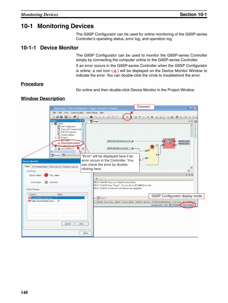
Monitoring Devices Section 10-1
10-1 Monitoring DevicesThe G9SP Configurator can be used for online monitoring of the G9SP-seriesController's operating status, error log, and operation log.
10-1-1 Device MonitorThe G9SP Configurator can be used to monitor the G9SP-series Controllersimply by connecting the computer online to the G9SP-series Controller.
If an error occurs in the G9SP-series Controller when the G9SP Configuratoris online, a red icon ( ) will be displayed on the Device Monitor Window toindicate the error. You can double-click the circle to troubleshoot the error.
ProcedureGo online and then double-click Device Monitor in the Project Window.
Window Description
Connect
"Error" will be displayed here if an error occurs in the Controller. You can check the error by double-clicking here.
G9SP Configurator display mode
148

Monitoring Devices Section 10-1
Device MonitorThe following status is displayed in the Device Monitor Window.
10-1-2 Monitoring StatusG9SP-series Controller’s operating modes and current errors can be checked.
Display element Description
(gray) Offline The G9SP Configurator is not online with the G9SP-series Controller.
(white) Configuring: Normal
Memory Cassette: Normal
The G9SP-series Controller is waiting to be con-figured or data is being backed up or restored with a Memory Cassette.
(green) IDLE: Normal The G9SP-series Controller is in IDLE Mode.
(blue) RUN: Normal The G9SP-series Controller is in RUN Mode.
(red) Alarm An error has occurred in the G9SP-series Con-troller.
Displays error information and troubleshooting procedures.
Shows if there are any errors or warnings currently in the Controller.
Gives the current operating mode of the Controller.
149

Monitoring Devices Section 10-1
10-1-3 Error LogPast and present G9SP-series Controller errors can be checked. Up to tenerrors are stored in the nonvolatile memory in the G9SP-series Controller.They are still retained even when the power is turned OFF and back ON.When more than 10 records are stored, the oldest records are deleted.
Precautions for Correct Use
Details on the error can be displayed by clicking the Help Button. This infor-mation is also provided in SECTION 13 Troubleshooting of this manual. Referto one of these and remove the cause of the error.
Additional Information
• The Unit Conduction Time is the total time that the G9SP-series Controllerhas been operating normally with the power ON. The time is saved everysix minutes.
• The error log list is not updated by moving between tabs (i.e., openinganother tab page and then again opening the Error Log List Tab Page). Toupdate the display, you must click Update Button.
Displays the contents of the error. Displays the unit ON time when the error occurred.
Newer
Older
Clears all errors from the error log.
Used to save the error log in a CSV-format file.
The error log is not updated when the Error Log List Tab Page is displayed. Always click the Update Button.
150

Monitoring Devices Section 10-1
10-1-4 Operation LogOperations that have been performed in the G9SP-series Controller can bechecked in the operation log. Up to 10 operations are stored in the nonvolatilememory in the G9SP-series Controller. They are still retained even when thepower is turned OFF and back ON. When more than 10 records are stored,the oldest records are deleted.
Stored Operations The following operations are stored in the operation log list.
Precautions for Correct Use
Only operations that are completed successfully are saved in the operationlog list.
Display the operation.
Displays the unit ON time when the operation was executed.
Newer
Older
Clears all operations from the operation log.
Used to save the operation log in a CSV-format file.
The operation log is not updated while the Operation Log List Tab Page is displayed. Always click the Update Button.
Stored operation Description
Power ON or emulating cycling power The G9SP-series Controller was turned ON or reset from the G9SP Configurator.
Out of box reset The G9SP-series Controller was reset to the default settings.
Download The configuration data was downloaded from the G9SP Configurator.
Lock/Unlock The configuration was locked or unlocked from the G9SP Configurator.
Change Mode The operating mode was changed from the G9SP Configurator.
Start/stop of force mode Force Mode was started or ended from the G9SP Configurator.
Change device password The Device Password was changed from the G9SP Configurator.
Clear error log The error log was cleared from the G9SP Configurator.
Backup to Memory Cassette The configuration data was backed up from the G9SP-series Controller to the Memory Cassette.
Restore from Memory Cassette Configuration data was restored from the Memory Cassette to the G9SP-series Controller.
151

Monitoring Programs Section 10-2
10-2 Monitoring Programs
10-2-1 Program MonitorThe G9SP Configurator can be used to graphically monitor program executionin the G9SP-series Controller.
Procedure
1,2,3... 1. Go online and then click the Program Monitor Icon .
2. The background of the Program Window will change to light blue and “On-line Monitor” will be displayed at the lower right of the window.
Window Description
Additional Information
• The display of function blocks with errors in the Output Window can beupdated by selecting Search Failed Function Blocks from the OnlineDebug Menu.
• The program and configuration data, such as the system settings, cannotbe changed while monitoring the program. End program monitoring tochange them.
Background: Light green
When a value is "ON, " changes to green.
If an error occurs, the function block changes to red.
Displays function blocks where errors have occurred. Double-click a line to jump to the relevant page.
152

Monitoring Programs Section 10-2
10-2-2 Watch WindowThe Watch Window of the G9SP-series Controller can be used to increase theefficiency of debugging.
Monitoring I/O Tag ValuesYou can register any I/O tags to the Watch Window to monitor the ON/OFFstatus in the Watch Window. This is convenient for monitoring changes in thevalues of I/O tags that are located on different pages, as shown below.
Example: Simultaneously Monitoring I/O Tags on Different Pages
To check the value of an output tag on page 2 when an input tag on page 1changes, the output tag can be registered to the Watch Window so that thestatus of both tags can be monitored while displaying page 1.
Analysis Displays for Related I/O TagsWith the G9SP Configurator, the I/O tags that are related to I/O tags that areregistered to the Watch Window can be analyzed. As shown in the followingexample, input tags related to an output tag are displayed, and then the outputcan be checked to make sure it turns OFF when one of the input tags turnsOFF.
Page 1
Page 2
Registered in Watch Window
153

Monitoring Programs Section 10-2
Example: Confirming an Output to See If It Turns OFF Correctly
The output tag to be checked is registered to the Watch Window and then atree hierarchy is opened for the output tag. The related input tags are dis-played in a list and can be turned ON and OFF to monitor the correspondingchanges in the output tag. This enables effective monitoring to help preventomitting items that need to be checked.
Registering and Deleting I/O Tags in the Watch Window
Registering Individual I/O TagsRight-click the I/O tag in the Program Window or I/O Tag List Window andselect Register to Watch Window.
Registering All I/O Tags in UseClick the Register Button in the Watch Window.
Deleting Individual I/O TagsRight-click an I/O tag in the Watch Window and select Clear.
Deleting All I/O Tags from the Watch ListClick the Clear Button in the Watch Window.
Additional Information
You can save all of the I/O tags in the Watch Window and the list of related I/Otags in a CSV-format file. This can be used to provide shutoff conditions forthe Safety Output devices that are being used.
Output tag to be checked
Input tags to be checked
154

Debugging in Force Mode Section 10-3
10-3 Debugging in Force ModeI/O tags can be force-set and force-reset in the Program Monitor Window.When an I/O tag is force-set or force-reset, the I/O status used in the programis turned ON or OFF regardless of the actual ON/OFF status of the I/O termi-nals or communications data. This can be used to check the wiring of outputsand check operation of the G9SP-series Controller even when communica-tions are not yet connected to enable efficient debugging.
Precautions for Correct Use
• Force-setting and force-resetting can be performed only when the configu-ration data of the G9SP-series Controller is unlocked.
• Program execution is stopped and the G9SP-series Controller enters theIDLE Mode when Force Mode is ended or Force Mode times out.
!WARNING Outputs may operate, possibly resulting in serious injury. Take sufficient safetymeasures before force-setting or force-resetting tags in the program.
10-3-1 Force ModeIt is necessary to change the G9SP-series Controller to Force Mode to force-set or force-reset I/O.
Starting Force ModeYou must input the Device Password to change to Force Mode. Force Modecan be entered only when the configuration data in the G9SP-series Control-ler is unlocked.
Monitoring Force Mode TimeA limit can be set for the time that the G9SP-series Controller will continue inForce Mode. The duration time is specified when Force Mode is started orrestarted. The upper limit of the duration time is 24 hours. The G9SP-seriesController will end Force Mode if the specified duration time elapses.
Mode change (RUN)
Mode change (IDLE)
Mode change (RUN)
Mode change (IDLE)Force Mode
Force Mode starts.
IDLE RUN
IDLE RUN
Force Mode ends or times out.
Force Mode starts.
155

Debugging in Force Mode Section 10-3
Ending Force ModeThere are three ways to end Force Mode.
Ending Force Mode with the G9SP Configurator• Program execution is stopped and the G9SP-series Controller enters the
normal IDLE Mode when Force Mode is ended or Force Mode times out.
• The I/O that were force-set or force-reset are returned to the actual valueswhen Force Mode ends.
Elapse of Force Mode Duration Time• Program execution is stopped and the G9SP-series Controller enters the
IDLE Mode when the Force Mode Duration Time expires.
• The I/O that were force-set or force-reset are returned to the actual valueswhen Force Mode ends.
Changing Controller to a Mode Other Than IDLE or RUNThe mode will be changed by downloading, resetting, turning OFF the powersupply. The Force Mode will continue, however, if a change is made betweenIDLE Mode and RUN Mode.
Force Mode at StartupIf the power supply is turned OFF while the G9SP-series Controller is in ForceMode, the G9SP-series Controller will start the next time in a normal mode.Start the Force Mode again if required.
Procedure and Windows
1,2,3... 1. Starting Force Mode
Press the (Start/Restart Force Mode) Button in the Program Monitor-ing Window. Enter the Device Password and duration time in the followingdialog box. The background in the Program Window will change to orangeand “Force Mode” will be displayed at the lower right of the window.
Input tag N actual data
Input tag N force-set/reset data
Start of Force Mode
Force-set
Force-reset
Force-set
End of Force Mode
Enter the Force Mode Duration Time. The upper limit is 1,440 minutes (24 hours).
Enter the Device Password.
156

Debugging in Force Mode Section 10-3
2. Force-setting/resetting I/O Tags
Right-click the desired I/O tag and then select one of the following buttons.
Closing the Program Monitor While Continuing in Force ModeYou can close the Program Monitor while continuing in Force Mode.
ProcedureClose the Program Monitor. The force-set and force-reset status of the I/Otags that has been set until that point will be held.
Procedure for RestartingOnce the Program Monitor Window has been closed, the right to performforce-set or force-reset I/O tags will be lost. To force-set or force-reset I/O tags
again, click the (Start/Restart Force Mode) Button, and then enter theDevice Password and duration time. You will be able to obtain the right toforce-set or force-reset I/O tags with the force-set or force-reset status thatwas saved.
Extending the Duration Time for Force Mode
Click the (Start/Restart Force Mode) Button to extend the duration timefor Force Mode.
Button Operation Description
Force-set The output will be turned ON regardless of the actual ON/OFF status.
Force-reset The output will be turned OFF regardless of the actual ON/OFF status.
Reverse status Reverses the current ON/OFF status.
--- Cancel forced status The force-set or force-reset status will be cleared and the output will return to the actual ON/OFF status.
157
Safety Validation and Preparations for Operation Section 10-4
10-4 Safety Validation and Preparations for OperationThe following operations are performed after checking G9SP-series Controlleroperation and completing debugging and before starting actual operation.
1. Performing safety validation testing (user testing)
2. Backing up data to the Memory Cassette
3. Printing and saving a report
10-4-1 Performing Safety Validation Testing (User Testing) Safety validation testing is performed to confirm that all of the Safety Func-tions of the entire system containing the G9SP-series Controller are operatingcorrectly. After completing safety validation testing, the configuration is lockedto protect it from unintentional changes.
Additional Information
Locking the configuration enables automatic operation of the G9SP-seriesController in RUN Mode. Refer to 9-3 Configuration Lock and Automatic Oper-ation for details.
!WARNING Serious injury may possibly occur due to loss of required safety functions.Perform user testing and confirm that all of the G9SP-series Controller's con-figuration data and operation is correct before starting system operation.
10-4-2 Backing Up Data to the Memory CassetteAfter the configuration data is locked, it is backed up to a Memory Cassette.Refer to SECTION 11 Backup and Restore Data Using Memory Cassette forMemory Cassette functions, details, and procedures.
Additional Information
• Memory Cassettes can be used to greatly reduce the work required inreplacing a G9SP-series Controller. We recommend that you use MemoryCassettes.
• Configuration data must be locked before it can be backed up to a MemoryCassette.
10-4-3 Outputting and Saving ReportsAfter the configuration data has been completed, it can be checked in areport, which can be printed or saved as required. Refer to 6-2-5 Displayingand Printing Reports for the procedures.
158

Maintenance and Inspections
SECTION 11Backup and Restore Data Using Memory Cassette
This section describes how to use Memory Cassettes.
11-1 Overview . . . . . . . . . . . . . . . . . . . . . . . . . . . . . . . . . . . . . . . . . . . . . . . . . . . . . 160
11-1-1 Memory Cassette Operations . . . . . . . . . . . . . . . . . . . . . . . . . . . . . . 160
11-1-2 Application Example . . . . . . . . . . . . . . . . . . . . . . . . . . . . . . . . . . . . 160
11-2 Backing Up Data to the Memory Cassette . . . . . . . . . . . . . . . . . . . . . . . . . . . 162
11-3 Restoring Data to G9SP-series Controller . . . . . . . . . . . . . . . . . . . . . . . . . . . 164
11-4 Checking Configuration Data Using Indicators . . . . . . . . . . . . . . . . . . . . . . . 167
159

Overview Section 11-1
11-1 OverviewThe maintenance efficiency of the G9SP-series Controller can be improved byusing an optional CP1W-ME05M Memory Cassette.
11-1-1 Memory Cassette OperationsWith the G9SP-series Controller, configuration data can be backed up fromthe G9SP-series Controller to the Memory Cassette and settings can berestored to the G9SP-series Controller from the Memory Cassette withoutusing a computer.
11-1-2 Application ExampleThe operations of the G9SP-series Controller's Memory Cassette can beused for the following applications.
Replacement of the G9SP-series Controller Due to FailureIf replacing the G9SP-series Controller is required due to failure during opera-tion, the configuration data can be set (i.e., restored) to the replacementG9SP-series Controller without using a computer. Once restoring the datahas been completed, the replacement G9SP-series Controller will automati-cally start to operate in the same way as the previous Controller.
Backup
Restore
Memory Cassette operations
CP1W-ME05M
G9SP-series Controller
Backup Restore
A computer is not required. A computer is not required.
G9SP-series Controller
Configuration data is backed up from the G9SP-series Controller to the Memory Cassette.
Configuration data stored in the Memory Cassette is set to the G9SP-series Controller.
Memory Cassette
MEMORY
Faulty Controller
G9SP-series Controller G9SP-series Controller
Insert the Memory Cassette into the replacement Controller and start the Controller to automatically load the configuration data to the replacement Controller and restart operation.
Replacement Controller
* The configuration data must be backed up in the Memory Cassette in advance.
MEMORY
160

Overview Section 11-1
Updating G9SP-series Controller's Configuration Data at Version Upgrade of Existing Equipment
If updating the G9SP-series Controller's configuration data is required due toa version upgrade of existing equipment, the new configuration data can beset (i.e., restored) without using a computer. Once restoring has been com-pleted and updating has been performed, the G9SP-series Controller willautomatically start to operate in the same way as before updating.
Copying G9SP-series Controller Data for Mass Production of Equipment with Identical Contents
Identical settings can be easily made to multiple G9SP-series Controllersusing one Memory Cassette when mass production of identical equipment isperformed. Once restoring has been completed, the G9SP-series Controllerwill automatically start to operate when the power supply is turned ON.
Precautions for Safe Use
Once restoring data has been completed using the Memory Cassette, theG9SP-series Controller will automatically start to operate. Be sure to alwaysturn OFF the power supply to power lines and check system safety beforerestoring data with a Memory Cassette.
Precautions for Correct Use
Make sure the power supply of the G9SP-series Controller is OFF wheninserting or removing the Memory Cassette. Inserting or removing the Mem-ory Cassette while the power is being supplied may cause failure of theG9SP-series Controller.
Removed
G9SP-series Controller
Before updating
After updating
Insert a Memory Cassette containing the updated configuration data into the G9SP-series Controller and start the Controller. The updated configuration data will be loaded to the Controller to restart operation.
* The configuration data must be backed up in the Memory Cassette in advance.
MEMORY
MEMORY
Operation can be restarted simply by inserting a Memory Cassette containing the updated configuration data into the G9SP-series Controller and starting the Controller. The updated configuration data will be loaded to the Controller.
Inserted Inserted
Inserted
G9SP-series Controller G9SP-series Controller G9SP-series Controller
* The configuration data must be backed up in the Memory Cassette in advance.
MEMORY
161
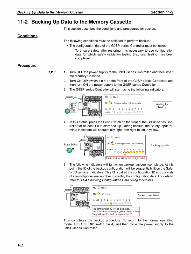
Backing Up Data to the Memory Cassette Section 11-2
11-2 Backing Up Data to the Memory CassetteThis section describes the conditions and procedures for backup.
ConditionsThe following conditions must be satisfied to perform backup.
• The configuration data of the G9SP-series Controller must be locked.
To ensure safety after restoring, it is necessary to use configurationdata for which safety validation testing (i.e., user testing) has beencompleted.
Procedure
1,2,3... 1. Turn OFF the power supply to the G9SP-series Controller, and then insertthe Memory Cassette.
2. Turn ON DIP switch pin 4 on the front of the G9SP-series Controller, andthen turn ON the power supply to the G9SP-series Controller.
3. The G9SP-series Controller will start using the following indicators.
4. In this status, press the Push Switch on the front of the G9SP-series Con-troller for at least 1 s to start backup. During backup, the Safety Input ter-minal indicators will sequentially light from right to left in yellow.
5. The following indicators will light when backup has been completed. At thispoint, the ID of the backup configuration will be sequentially lit on the Safe-ty I/O terminal indicators. This ID is called the configuration ID and consistsof a four-digit decimal number to identify the configuration data. For details,refer to 11-4 Checking Configuration Data Using Indicators.
This completes the backup procedure. To return to the normal operatingmode, turn OFF DIP switch pin 4, and then cycle the power supply to theG9SP-series Controller.
Not lit
Flashing yellow (0.5-s intervals)
MS
MC
IN LED 0 1 2 3 4 5 6 7 8 9
Not lit
Waiting for backup
MEMORY
Not lit
Flashing yellow (0.25-s intervals)
MS
MC
IN LED 0 1 2 3 4 5 6 7 8 9
The indicators will light from right to left.
Push Switch Backing up data
MEMORY
Not lit
Lit yellow
MS
MC
IN LED 0 1 2 3 4 5 6 7 8 9
The configuration ID will be displayed.The I/O indicators will light yellow one at a time. They will light for the four digits of the ID.
Backup completed.
MEMORY
162

Backing Up Data to the Memory Cassette Section 11-2
If an error occurs during the backup operation, the ERR/ALM indicator willlight red, and the terminal number will light red on the Safety Input terminalindicators to indicate the error details. Refer to 13-2 Error Details and Mea-sures to remove the error.
Precautions for Correct Use
• Backing up data to the Memory Cassette can be performed only when theG9SP-series Controller's configuration data is locked. Conduct a safetyconfirmation test (i.e., user test) and lock the configuration data beforeperforming the backup.
• Complete backup in advance, before using the G9SP-series Controller ifthe Memory Cassette is going to be used for efficient replacement of theG9SP-series Controller in the event of failure. Backup may not be per-formed correctly after failure of the G9SP-series Controller.
• Performing a backup overwrites the data on the Memory Cassette. Besure to confirm that the Memory Cassette contains no required databefore performing backup.
Note (1) Formatting the Memory Cassette is not required.
(2) The contents of the Memory Cassette can be checked by verifying theconfiguration ID to prevent setting incorrect configuration data when re-storing data to the G9SP-series Controller is performed from the MemoryCassette. To enable performing this verification, record the configurationID when performing backup.
Not lit
Lit yellow
MS
MC
IN LED 0 1 2 3 4 5 6 7 8 9
The corresponding I/O indicators will light to show the type of error.
Lit redERR/ALM
Backup error
MEMORY
163
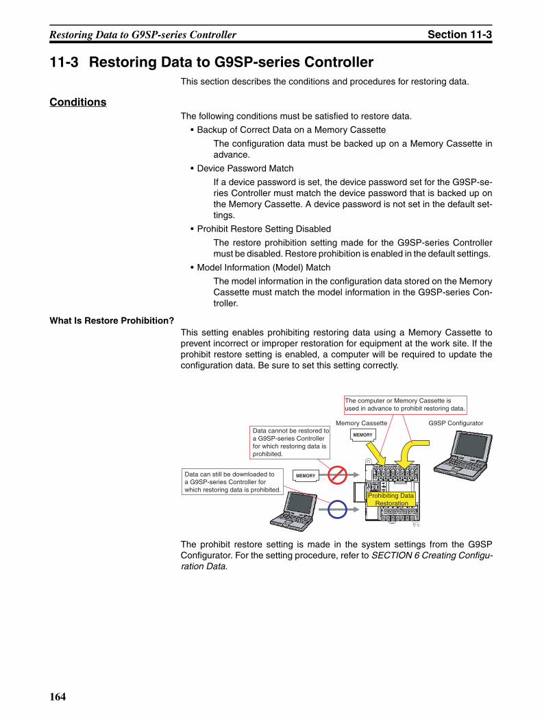
Restoring Data to G9SP-series Controller Section 11-3
11-3 Restoring Data to G9SP-series ControllerThis section describes the conditions and procedures for restoring data.
ConditionsThe following conditions must be satisfied to restore data.
• Backup of Correct Data on a Memory Cassette
The configuration data must be backed up on a Memory Cassette inadvance.
• Device Password Match
If a device password is set, the device password set for the G9SP-se-ries Controller must match the device password that is backed up onthe Memory Cassette. A device password is not set in the default set-tings.
• Prohibit Restore Setting Disabled
The restore prohibition setting made for the G9SP-series Controllermust be disabled. Restore prohibition is enabled in the default settings.
• Model Information (Model) Match
The model information in the configuration data stored on the MemoryCassette must match the model information in the G9SP-series Con-troller.
What Is Restore Prohibition?This setting enables prohibiting restoring data using a Memory Cassette toprevent incorrect or improper restoration for equipment at the work site. If theprohibit restore setting is enabled, a computer will be required to update theconfiguration data. Be sure to set this setting correctly.
The prohibit restore setting is made in the system settings from the G9SPConfigurator. For the setting procedure, refer to SECTION 6 Creating Configu-ration Data.
G9SP Configurator
Prohibiting Data Restoration
Memory Cassette
The computer or Memory Cassette is used in advance to prohibit restoring data.
Data can still be downloaded to a G9SP-series Controller for which restoring data is prohibited.
Data cannot be restored to a G9SP-series Controller for which restoring data is prohibited.
MEMORY
MEMORY
164

Restoring Data to G9SP-series Controller Section 11-3
Procedure
1,2,3... 1. Turn OFF the power supply to the G9SP-series Controller, and then insertthe Memory Cassette.
2. Turn OFF DIP switch pin 4 on the front of the G9SP-series Controller, andthen turn ON the power supply to the G9SP-series Controller.
The system will start in restore standby status at step 3 if the configurationdata stored in the Memory Cassette does not match the configuration datastored in the G9SP-series Controller.
3. After startup, the ID of the configuration data on the Memory Cassette willlight sequentially on the Safety Input terminal indicators of the G9SP-se-ries Controller.
4. Once the display configuration ID has been verified and it is confirmed thatthe intended configuration data has been stored in the Memory Cassette,press the Push Switch on the front of the G9SP-series Controller for atleast 1 s to start restoring data. During the restore operation, the Safety In-put terminal indicators will be sequentially lit from left to right in yellow.
5. Once the restore operation has been completed, the G9SP-series Control-ler will restart and operate in RUN Mode with the configuration locked.
Not lit
Flashing yellow (0.5-s intervals)
MS
MC
IN LED 0 1 2 3 4 5 6 7 8 9
Waiting for restore
The configuration I/O of the configuration data stored in the Memory Cassette is displayed.The I/O indicators will light yellow one at a time. They will light for the four digits of the ID.
MEMORY
Not lit
Flashing yellow (0.25-s intervals)
MS
MC
IN LED 0 1 2 3 4 5 6 7 8 9
The indicators will light from left to right.
Push Switch Restoring data
MEMORY
Lit green
Not lit
MS
MC
Lit yellowLOCK
Restore operation completed.
MEMORY
165

Restoring Data to G9SP-series Controller Section 11-3
If an error occurs during the restore operation, the ERR/ALM indicator willlight red, and a terminal number will light red to indicate the error details onthe Safety Input terminal indicators. Refer to 13-2 Error Details and Measuresto remove the error.
Precautions for Correct Use
• Operation will always start in restore waiting status when startup is per-formed with the Memory Cassette inserted into the G9SP-series Controllerusing the default settings. Make sure the Memory Cassette is not insertedwhen downloading the configuration data from a computer.
• Verification of the configuration ID is performed to prevent restoring incor-rect configuration data.
!WARNING Serious injury may possibly occur due to loss of required safety functions.Once the data has been restored from the Memory Cassette, check that theconfiguration data of the G9SP-series Controller is correct in that it operatesproperly and carry out the validation testing (User Testing).
Not lit
Lit yellow
MS
MC
IN LED 0 1 2 3 4 5 6 7 8 9
The corresponding I/O indicators will light to show the type of error.
Lit redERR/ALM
Restore error
MEMORY
166
Checking Configuration Data Using Indicators Section 11-4
11-4 Checking Configuration Data Using IndicatorsAn ID can be displayed on the I/O indicators of the G9SP-series Controller toidentify the configuration data. This is used to check the configuration data inpresent operation or to check configuration data on the Memory Cassettebefore restoring data.
What Is a Configuration ID?The configuration ID is a 4-digit decimal code that is generated from the con-figuration data created on the G9SP Configurator. Data is generated from set-tings not related to safety, such as function block placement information and I/O comments, in addition to safety-related settings, such as Safety I/O terminalsettings and programming. Therefore, the configuration ID is a different valueeven when there have been changes in safety-related settings or changesthat do not affect operation of the G9SP-series Controller, such as changes infunction block assignment.
What Is a Safety Signature?This is a code that is generated from the safety-related settings made with theG9SP Configurator. It is used to check if there has been a change that willaffect the operation of the G9SP-series Controller.
Checking with the G9SP Configurator
1,2,3... 1. Right-click the unit name in the Project Window and select Property.
2. Click the Signature Tab.
Checking the Configuration IDThe section describes how to check the configuration ID.
Checking the Configuration Data in Present Operation
1,2,3... 1. Press the Push Switch for at least 1 s on the front of the G9SP-series Con-troller when it is operating in IDLE Mode or RUN Mode.
2. After 1 s, the configuration ID will be displayed on the Safety Input terminalindicators of the G9SP-series Controller.
Checking the Configuration Data Stored on the Memory CassetteRefer to step 3 in 11-3 Restoring Data to G9SP-series Controller.
Code Contents
Signature code This is a four-digit hexadecimal code generated from safety-related settings.
Signature date This is the time when the safety-related settings were made using the G9SP Configurator.
167

Checking Configuration Data Using Indicators Section 11-4
168

Maintenance and Inspections
SECTION 12Maintenance and Inspections
This section describes the inspections for G9SP-series Controller and precautions when replacing the G9SP-seriesController.
12-1 Inspections . . . . . . . . . . . . . . . . . . . . . . . . . . . . . . . . . . . . . . . . . . . . . . . . . . . 170
12-2 G9SP-series Controller Replacement Precautions . . . . . . . . . . . . . . . . . . . . . 171
169

Inspections Section 12-1
12-1 InspectionsDaily or periodic inspections are required in order to maintain the G9SP-series Controller functions in good operating condition. In this section, theG9SP-series Controller is referred to as simply the “Controller.”
• Confirm that the Controller is being used within the specifications.
• Confirm that the Controller is mounted and wired correctly.
• Check the safety functions in order to maintain their operating reliability ata constant level.
• Use the error log to check for non-fatal errors.
Periodic Inspection Points
No. Item Inspection Criteria Action
1 Source power supply
Check for voltage fluctuations at the power supply terminals.
The voltage must be within the allowable voltage fluctuation range. (Refer to SECTION 2 Part Names and Specifica-tions.)
Use a voltage tester to check the power supply at the termi-nals. Take necessary steps to bring voltage fluctuations within limits.
2 Ambient envi-ronment
Check the ambient tempera-ture. (Inside the control panel if the Controller is in a control panel.)
0 to 55°C (Refer to SECTION 2 Part Names and Specifica-tions.)
Use a thermometer to check the temperature and ensure that the ambient temperature remains within the allowed range of 0 to 55°C.
Check the ambient humidity. (Inside the control panel if the Controller is in a control panel.)
10% to 90% (with no conden-sation.) (Refer to SECTION 2 Part Names and Specifica-tions.)
Use a hygrometer to check the humidity and ensure that the ambient humidity remains between 10% and 90%. Make sure that condensation does not occur due to rapid changes in temperature.
Check that the Controller is not in direct sunlight.
Not in direct sunlight Protect the Controller if neces-sary.
Check for accumulation of dirt, dust, salt, metal filings, etc.
No accumulation Clean and protect the Control-ler if necessary.
Check for water, oil, or chemi-cal sprays hitting the Control-ler.
No spray on the Controller Clean and protect the Control-ler if necessary.
Check for corrosive or flamma-ble gases in the area of the Controller.
No corrosive or flammable gases
Check by smell or use a gas sensor.
Check the level of vibration or shock applied to the Controller.
Vibration and shock must be within specifications. (Refer to SECTION 2 Part Names and Specifications.)
Install cushioning or shock absorbing material if neces-sary.
Check for noise sources near the Controller.
No significant noise sources (Refer to SECTION 2 Part Names and Specifications.)
Either separate the Controller and noise source or protect the Controller.
3 Installation and wiring
Check that all terminals blocks between Units are inserted and locked fully.
No looseness (Refer to SEC-TION 4 Installation and Wir-ing.)
Press the terminal block on completely and lock them with the screws.
Check that cable connectors are fully inserted and locked.
No looseness (Refer to SEC-TION 4 Installation and Wir-ing.)
Press the connectors on com-pletely and lock them.
Check for loose screws in external wiring.
No looseness Tighten loose screws with a Phillips screwdriver.
4 Performing safety valida-tion testing (user testing)
Make sure that all safety func-tions are operating correctly.
The safety functions must be operating as intended.
Remove any errors and then recheck the operation of all safety functions.
170

G9SP-series Controller Replacement Precautions Section 12-2
12-2 G9SP-series Controller Replacement PrecautionsWhen replacing a Controller after discovering a problem during inspection,pay attention to the following points.
• Do not attempt to disassemble, repair, or modify the Units in any way.Doing so may impair the original safety functions.
• Make sure that safety can be assured when replacing the Unit.
• To prevent electric shock or unexpected operation, always turn OFF thepower before replacing the Unit.
• After replacing the Unit, check the new Unit to make sure that there are noerrors.
Precautions for Safe Use
After replacing a Controller, reset the program and all configuration datarequired for restarting the user program and confirm that the safety functionsare operating normally before starting this operation.
Making Settings and Wiring the New Unit
Replacing and Wiring the UnitRemove the faulty Unit and mount and wire the new Unit.
Refer to SECTION 4 Installation and Wiring.
Downloading Configuration Data and Checking Operation
Operation Using the G9SP ConfiguratorDownload the configuration data to the new Controller and check the opera-tion of the safety system.
Refer to SECTION 8 Connecting Online and Downloading to the G9SP-se-ries Controller.
Refer to SECTION 9 Operation and Operating Modes.
Operation Using a Memory CassetteInsert the Memory Cassette in the new Controller, restore the configurationdata, and check the operation of the safety system.
Refer to SECTION 11 Backup and Restore Data Using Memory Cassette.
171

G9SP-series Controller Replacement Precautions Section 12-2
172

Maintenance and Inspections
SECTION 13Troubleshooting
This section describes how to troubleshoot problems that may occur with the G9SP-series Controller.
13-1 Overview of Troubleshooting . . . . . . . . . . . . . . . . . . . . . . . . . . . . . . . . . . . . . 174
13-1-1 Errors and Remedies. . . . . . . . . . . . . . . . . . . . . . . . . . . . . . . . . . . . . 174
13-1-2 Checking the Indicators . . . . . . . . . . . . . . . . . . . . . . . . . . . . . . . . . . 174
13-1-3 Identifying Errors . . . . . . . . . . . . . . . . . . . . . . . . . . . . . . . . . . . . . . . 176
13-2 Error Details and Measures. . . . . . . . . . . . . . . . . . . . . . . . . . . . . . . . . . . . . . . 177
13-2-1 Fatal Errors . . . . . . . . . . . . . . . . . . . . . . . . . . . . . . . . . . . . . . . . . . . . 177
13-2-2 Non-fatal Errors . . . . . . . . . . . . . . . . . . . . . . . . . . . . . . . . . . . . . . . . 179
173

Overview of Troubleshooting Section 13-1
13-1 Overview of TroubleshootingThis section describes how to troubleshoot errors that occur in the G9SP-series Controller.
13-1-1 Errors and RemediesUse the following procedure when an error occurs.
13-1-2 Checking the IndicatorsThe type of error that occurred can be determined by checking the indicatorson the front of the G9SP-series Controller.
Check the indicators.
Problem occurs
Identify the error.
Implement countermeasures
End
Check the indicators on the front of the Controller to determine the error status.
Use the G9SP Configurator to read the detailed error status.
Take measures to eliminate the error that occurred and to prevent it from occurring again.
MS FORCE LOCK ERR/ALM
MC COMM OUT PWR
I/O Status
Green Red Yellow Yellow Red Yellow Yellow Green Yellow RedNormal operating status
--- --- --- --- --- Normal operating status after complet-ing user testing
--- --- --- --- --- Normal operating status during user testing
--- --- --- --- --- --- Operating status is normal, but the Safety Output does not turn ON.
Stopped but no error detected--- --- --- --- --- --- Internal power not supplied
--- --- --- --- --- --- Stopped in IDLE Mode
--- --- --- --- --- --- Stopped in CONFIGURATION Mode
--- --- --- --- --- --- Memory Cassette operation in progress (backup/restore)
Fatal error detected--- --- --- --- --- --- --- --- Critical status: System error detected
--- --- --- --- --- --- --- Abort status: Minor error detected
--- --- --- --- --- Error detected in Memory Cassette operation (backup/restore)
Non-fatal error detected--- --- --- --- --- --- --- --- --- Non-fatal error detected
174
Overview of Troubleshooting Section 13-1
: Not lit : Flashing : Lit ---: Not relevant
Normal Operating StatusIn this status, the G9SP-series Controller is executing programming and oper-ating normally. Operating status is divided into the following two states. Fordetails, refer to 9-3 Configuration Lock and Automatic Operation.
Stopped But No Error DetectedThe G9SP-series Controller is not executing programming and operation isstopped. However, no particular error has been detected in this status, and soobserve the following points to perform operation.
Status Action
Normal operating status after complet-ing user testing
User testing has been completed, and normal operation is being performed in automatic operating mode. No particular measures are required.
Normal operating status during user testing
User testing has not been completed, and so operation is being performed with the configuration unlocked. The present operation is normal, but the system will start in IDLE Mode at the next startup. Change the operating mode from the G9SP Configurator at every startup until user testing has been com-pleted.
Operating status is normal, but the Safety Output does not turn ON.
The following causes are possible. If none of the actions cor-rects the problem, the Unit may be faulty. In that case, replace the Unit.
1. Check to see if the output tag is ON. Use the program monitor to see if the output tag is displayed in green, indicating that it is ON.
2. Check to see if the Safety Output terminal is set. Open the Safety I/O terminal settings to check the setting.
3. Either 24 V is not being applied to other Safety Output ter-minals or Standard Output terminals or the power supply positive terminal is not connected. If this occurs, the output power supply OFF test will fail, so the Safety Output will not turn ON for safety reasons. Check the wiring and cycle the output power supply.
Status Action
Internal power not supplied
Check the following before supplying the rated power.
• Is the power supply voltage within the specifications?• Is the wiring correct or connected properly?
The Unit may have failed if the measured voltage at terminal V1/G1 is normal. In that case, replace the Unit.
Stopped in IDLE Mode
1. Change the operating mode using the G9SP Configurator (9-2 Changing the Operating Mode).
2. Refer to 9-3 Configuration Lock and Automatic Operation if the system starts in IDLE Mode when it was previously op-erated in RUN Mode.
3. The mode will change from RUN Mode to IDLE Mode when the Force Mode times out. Take suitable measures, such as starting Force Mode again.
175
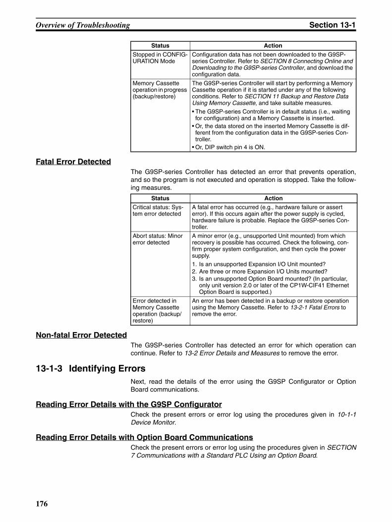
Overview of Troubleshooting Section 13-1
Fatal Error DetectedThe G9SP-series Controller has detected an error that prevents operation,and so the program is not executed and operation is stopped. Take the follow-ing measures.
Non-fatal Error DetectedThe G9SP-series Controller has detected an error for which operation cancontinue. Refer to 13-2 Error Details and Measures to remove the error.
13-1-3 Identifying ErrorsNext, read the details of the error using the G9SP Configurator or OptionBoard communications.
Reading Error Details with the G9SP ConfiguratorCheck the present errors or error log using the procedures given in 10-1-1Device Monitor.
Reading Error Details with Option Board CommunicationsCheck the present errors or error log using the procedures given in SECTION7 Communications with a Standard PLC Using an Option Board.
Stopped in CONFIG-URATION Mode
Configuration data has not been downloaded to the G9SP-series Controller. Refer to SECTION 8 Connecting Online and Downloading to the G9SP-series Controller, and download the configuration data.
Memory Cassette operation in progress (backup/restore)
The G9SP-series Controller will start by performing a Memory Cassette operation if it is started under any of the following conditions. Refer to SECTION 11 Backup and Restore Data Using Memory Cassette, and take suitable measures.
• The G9SP-series Controller is in default status (i.e., waiting for configuration) and a Memory Cassette is inserted.
• Or, the data stored on the inserted Memory Cassette is dif-ferent from the configuration data in the G9SP-series Con-troller.
• Or, DIP switch pin 4 is ON.
Status Action
Status Action
Critical status: Sys-tem error detected
A fatal error has occurred (e.g., hardware failure or assert error). If this occurs again after the power supply is cycled, hardware failure is probable. Replace the G9SP-series Con-troller.
Abort status: Minor error detected
A minor error (e.g., unsupported Unit mounted) from which recovery is possible has occurred. Check the following, con-firm proper system configuration, and then cycle the power supply.1. Is an unsupported Expansion I/O Unit mounted?2. Are three or more Expansion I/O Units mounted?3. Is an unsupported Option Board mounted? (In particular,
only unit version 2.0 or later of the CP1W-CIF41 Ethernet Option Board is supported.)
Error detected in Memory Cassette operation (backup/restore)
An error has been detected in a backup or restore operation using the Memory Cassette. Refer to 13-2-1 Fatal Errors to remove the error.
176
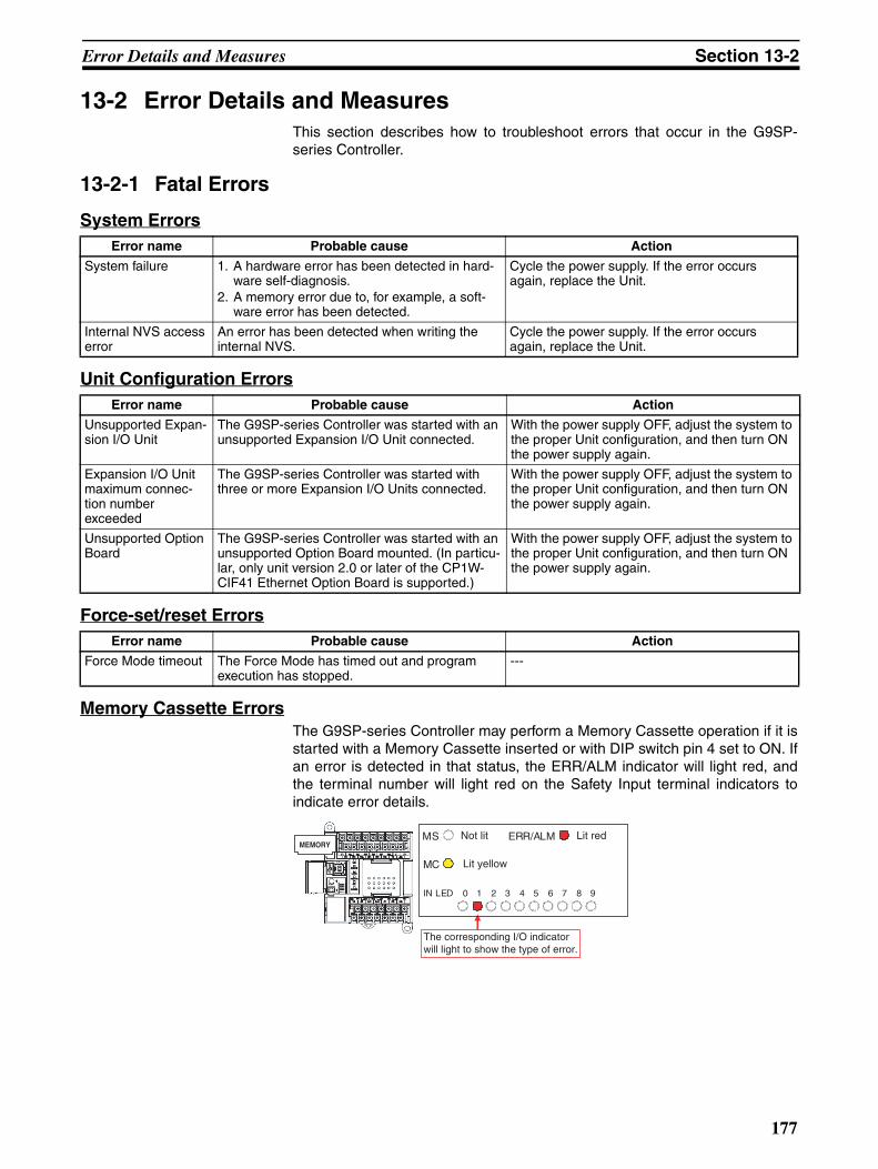
Error Details and Measures Section 13-2
13-2 Error Details and MeasuresThis section describes how to troubleshoot errors that occur in the G9SP-series Controller.
13-2-1 Fatal Errors
System Errors
Unit Configuration Errors
Force-set/reset Errors
Memory Cassette ErrorsThe G9SP-series Controller may perform a Memory Cassette operation if it isstarted with a Memory Cassette inserted or with DIP switch pin 4 set to ON. Ifan error is detected in that status, the ERR/ALM indicator will light red, andthe terminal number will light red on the Safety Input terminal indicators toindicate error details.
Error name Probable cause Action
System failure 1. A hardware error has been detected in hard-ware self-diagnosis.
2. A memory error due to, for example, a soft-ware error has been detected.
Cycle the power supply. If the error occurs again, replace the Unit.
Internal NVS access error
An error has been detected when writing the internal NVS.
Cycle the power supply. If the error occurs again, replace the Unit.
Error name Probable cause Action
Unsupported Expan-sion I/O Unit
The G9SP-series Controller was started with an unsupported Expansion I/O Unit connected.
With the power supply OFF, adjust the system to the proper Unit configuration, and then turn ON the power supply again.
Expansion I/O Unit maximum connec-tion number exceeded
The G9SP-series Controller was started with three or more Expansion I/O Units connected.
With the power supply OFF, adjust the system to the proper Unit configuration, and then turn ON the power supply again.
Unsupported Option Board
The G9SP-series Controller was started with an unsupported Option Board mounted. (In particu-lar, only unit version 2.0 or later of the CP1W-CIF41 Ethernet Option Board is supported.)
With the power supply OFF, adjust the system to the proper Unit configuration, and then turn ON the power supply again.
Error name Probable cause Action
Force Mode timeout The Force Mode has timed out and program execution has stopped.
---
Not lit
Lit yellow
MS
MC
IN LED 0 1 2 3 4 5 6 7 8 9
Lit red ERR/ALM
The corresponding I/O indicator will light to show the type of error.
MEMORY
177

Error Details and Measures Section 13-2
Note With a Controller with unit version 1.@, you cannot restore a configuration thatcontains two or more Single Beam Safety Sensors.
Error name I/O LED Probable cause Action
Memory Cassette not inserted or incor-rect Memory Cas-sette
Si1 lit red 1. Backup was started with a Memory Cassette not inserted or not inserted securely.
2. The G9SP-series Controller was started in Restore Mode with a Memory Cassette formatted using the CP1@ or a Memory Cassette containing incorrectly formatted da-ta.
Restoring Data:
1. With the power supply OFF, insert a Mem-ory Cassette securely, and then turn ON the power supply again.
2. With the power supply OFF, insert the cor-rect Memory Cassette, and then turn ON the power supply again.
If the error occurs again after this measure is taken, replace the Memory Cassette or the G9SP-series Controller.
Not Restoring Data:The G9SP-series Controller will attempt to restore data if it is waiting for configuration (i.e., default status) or the configuration data that is held does not match data on the Mem-ory Cassette. If restoring the data is not required, remove the Memory Cassette and cycle the power supply.
Memory Cassette removed or access error
Si2 lit red 1. The Memory Cassette was removed during execution of a Memory Cas-sette operation.
2. Hardware error in G9SP-series Controller or Memory Cassette
With the power supply OFF, insert the Mem-ory Cassette again, and then turn ON the power supply again. If the error occurs again, replace the G9SP-series Controller or Mem-ory Cassette.
Internal NVS access error during execu-tion of Memory Cas-sette functions
Si3 lit red Controller hardware failure Cycle the power supply. If the error occurs again, replace the Unit.
Model information (model) mismatch
Si4 lit red 1. The model information in the config-uration data stored on the Memory Cassette does not match the model information in the G9SP-series Con-troller.
2. The configuration data stored in the Memory Cassette is not supported by the unit version of the Controller. (See note.)
With the power supply OFF, insert the correct Memory Cassette, and then turn ON the power supply again.
Device password mismatch between restore Memory Cassette and unit
Si5 lit red The Device Password stored in the Memory Cassette does not match the Device Password in the G9SP-series Controller.
With the power supply OFF, insert the correct Memory Cassette, and then turn ON the power supply again.
Restore prohibit error
Si6 lit red An attempt was made to restore data to a G9SP-series Controller for which restore prohibition has been set.
Using the G9SP Configurator, 1) overwrite the configuration data or 2) reset to the default settings, and then insert the Memory Cassette again and cycle the power supply.
Incorrect configura-tion data at restore
Si7 lit red Incorrect data was detected when checking the configuration data stored in the Memory Cassette.
With the power supply OFF, insert the correct Memory Cassette, and then turn ON the power supply again.
Unconfigured Unit at backup
Si8 lit red The G9SP-series Controller contains no configuration data, and so backup to the Memory Cassette cannot be performed.
---
Unlocked unit at backup error
Si9 lit red The Controller's configuration data is not locked, and so backup to the Mem-ory Cassette cannot be performed.
---
178

Error Details and Measures Section 13-2
Additional Information
Errors related to the Memory Cassette are not saved in the error log in theG9SP-series Controller's internal nonvolatile memory. Read and check theerror before cycling the power supply.
13-2-2 Non-fatal Errors
Expansion I/O Unit Errors
Program Execution Errors
Option Board Communications Errors
Safety I/O Function ErrorsIf an error is detected in the self-diagnosis functions of Safety Input terminals,the ERR/ALM indicator on the G9SP-series Controller will flash red, and therelevant Safety I/O terminal indicator will light red or flash red.
Error name Probable cause Action
Expansion I/O Unit configuration mis-match
The system started with a configuration different from configuration set using the G9SP Configu-rator.
With the power supply OFF, adjust the system to the proper Unit configuration, and then turn ON the power supply again.
Expansion I/O bus error
Failure occurred when refreshing the Expansion I/O Unit. (The failure was the result of Expansion I/O Unit failure, improper contact, or noise inter-ference.)
With the power supply OFF, check the connec-tion to the Expansion I/O Unit. If the error occurs again, replace the Expansion I/O Unit or take measures against noise.
Error name Probable cause Action
Function block status error
A logic error was detected in function block exe-cution.
Refer to the G9SP-N@@@ Safety Controller Instructions Reference Manual (Cat. No. Z923).
Error name Probable cause Action
Option Board com-munications error, communications tim-eout
A timeout was detected in communications through the Option Board. (This includes discon-nected communications cable, Option Board fail-ure, improper contact, noise interference, communications partner failure, or communica-tions partner status change.)
With the power supply OFF, check the connec-tion to the Option Board. If the error occurs again, replace the Option Board, take measures against noise, or check the remote connection.
Option Board com-munications error, not mounted
The Option Board became loose after startup. With the power supply OFF, check the connec-tion to the Option Board, and then turn ON the power supply again.
Flashing green/lit green Flashing redERR/ALMMS
I/O LED 0 1 2 3 4 5 6 7 8 9
The I/O indicator of the terminal where the error was detected will light or flash red.
MEMORY
179

Error Details and Measures Section 13-2
Output Power Supply Errors
Safety Input Terminal Errors
Test Output Terminal Errors
Safety Output Terminal Errors
Error name Probable cause Action
Output PS voltage low
The correct output power is not being supplied.
Check the following before supplying the rated power.
• Is the power supply voltage within the specifications?• Is the wiring correct or connected properly?• Either 24 V is not being applied to the Safety Output terminals
or the power supply positive terminal is not connected.
The Unit may have failed if the measured voltage at terminal V2/G2 is normal. In that case, replace the Unit.
Output PS OFF cir-cuit error
An error has been detected in the output power supply OFF test.
Error name Probable cause Action
External test signal failure at Safety Input
An error was detected in evaluation of Safety Input terminals.
1. Contact of input signal lines to positive side of power supply lines.
2. Short-circuit between input signal lines. 3. Failure of externally connected device.
1./2. Check the external wiring.
3. Replace the externally connected device.
Internal circuit error at Safety Input
An error was detected in the internal circuits. Cycle the power supply. If the error occurs again, replace the Unit.
Discrepancy error at Safety Input
An error was detected in discrepancy evaluation of Safety Input terminals.
1. Input signal line ground fault or disconnection.2. Failure of connected device.3. Incorrect set value for discrepancy time.
1. Check the external wiring.2. Replace the externally connected device.3. Review the discrepancy time.
Error name Probable cause Action
Overload detected at Test Output
1. Output signal line ground fault2. Failure of externally connected device.
1. Check the external wiring.2. Replace the externally connected device.
Stuck-at-high detected at Test Out-put
1. Contact of output signal lines to positive side of power supply lines.
2. Internal circuit failure
1. Check the external wiring.2. Cycle the power supply. If the error occurs
again, replace the Unit.
Undercurrent detected using Mut-ing Lamp
1. Output signal line disconnection.2. Failure of externally connected device.
1. Check the external wiring.2. Replace the externally connected device.
Internal circuit error at Test Output
An error was detected in the internal circuits. Cycle the power supply. If the error occurs again, replace the Unit.
Error name Probable cause Action
Overcurrent detected at Safety Output
Failure of an externally connected device was detected.
Replace the externally connected device.
Short circuit detected at Safety Output
A ground fault in output signal lines was detected.
Check the external wiring.
Stuck-at-high detected at Safety Output
1. Contact of output signal lines to positive side of power supply lines.
2. Internal circuit failure3. Output power supply outside of specifications.
1. Check the external wiring.2. Cycle the power supply. If the error occurs
again, replace the Unit.3. Check the output power supply.
Dual channel viola-tion at Safety Output
Programming error Correct the program so that the same data is output when the Safety Output terminals are set to Dual-channel Mode.
Internal circuit error at Safety Output
An error was detected in the internal circuits. Cycle the power supply. If the error occurs again, replace the Unit.
180

Appendix AApplication Templates
Emergency Stop Pushbutton Application
Application Overview Motor M stops when emergency stop pushbutton S1 is pressed.
Wiring Example
Note Refer to SECTION 2 Part Names and Specifications for the terminal arrangement.
Timing Chart
Safety category/PL Safety device Stop category Reset
Equivalent to 4/PLe. Emergency stop pushbutton 0 Manual
E1 and E2: 24-VDC power suppliesS1: Emergency stop pushbutton S2: Reset switchKM1and KM2: Contactors M: Motor
KM1
KM2
EDM feedback
E-STOP pushed
More than 350 ms
E-STOP S111-12
Reset ON
E-STOP S121-22
Reset S2
More than 350 ms
E-STOP released
Discrepancy error
Discrepancyerror released
EDM error released
EDM error
More than 350 ms
181

Application Templates Appendix A
Safety I/O Terminal Settings
Program
Precautions for Safe Use
• Perform a function test every six months to detect contact welding failures on contactors.
• It is the user's responsibility to make sure that the entire system complies with standards.
• For safety reasons, two electrical switching elements and two mechanical actuators arealways necessary to detect electrical faults and mechanical faults.
Input Terminals Output Terminals
182

Application Templates Appendix A
Safety Door Application 1
Application OverviewMotor M stops when safety gate 1 (S1, S2) is opened.
Wiring Example
Note Refer to SECTION 2 Part Names and Specifications for the terminal arrangement.
Timing Chart
Safety I/O Terminal Settings
Safety category/PL Safety device Stop category Reset
Equivalent to 4/PLe. Safety limit switch 0 Auto
E1 and E2: 24-VDC power suppliesS1: Safety limit switchS2: Limit switch (NO contacts)KM1and KM2: Contactors M: Motor
KM1
KM2
EDM feedback
Gate opened Gate closed
Idle → Run
Safety limit switchS1
Limit switch S2
Input Terminals Output Terminals
183

Application Templates Appendix A
Program
Precautions for Safe Use
• Perform a function test every six months to detect contact welding failures on contactors.
• It is the user's responsibility to make sure that the entire system complies with standards.
• For safety reasons, two electrical switching elements and two mechanical actuators arealways necessary to detect electrical faults and mechanical faults.
184

Application Templates Appendix A
Safety Door Application 2
Application OverviewM1 stops when safety gate 1 (S3, S4) is opened. M2 stops when safety gate 2 (S5, S6) is opened.Both M1 and M2 stop when the emergency stop pushbutton S1 is pressed.
Wiring Example
Note Refer to SECTION 2 Part Names and Specifications for the terminal arrangement.
Timing Chart
Safety category/PL Safety device Stop category Reset
Equivalent to 4/PLe. Safety limit switches 1 and 2 0 Auto
Emergency stop pushbutton 0 Manual
S1
S3,S4 S5,S6
S2
E1 and E2: 24-VDC power suppliesS1: Emergency stop pushbutton S2: Reset switchS3 and S5: Safety limit switchesS4 and S6: Limit switches (NO contacts)KM1, KM2, KM3, and KM4: Contactors M1 and M2: Motors
E-STOP S1
Reset S2
E-STOP pushedGate opened
Gate close
EDM feedback (Si7)
Gate 1 (S3, S4)
Gate 2 (S5, S6)
KM3 and KM4 (So2 and So3)
EDM feedback (Si8)
KM1 and KM2 (So0 and So1)
Idle → Run
Reset ON
More than 350 ms
More than 350 ms
E-STOP released
185

Application Templates Appendix A
Safety I/O Terminal Settings
Program
Precautions for Safe Use
• Perform a function test every six months to detect contact welding failures on contactors.
• It is the user's responsibility to make sure that the entire system complies with standards.
• For safety reasons, two electrical switching elements and two mechanical actuators arealways necessary to detect electrical faults and mechanical faults.
Input Terminals Output Terminals
186

Application Templates Appendix A
Safety Light Curtain Application 1
Application OverviewThe output goes OFF when light is intercepted for both safety light curtain 1 (S2)and safety light curtain 2 (S3) simultaneously.
The output also goes OFF when emergency stop pushbutton S1 is pressed.
Wiring Example
Note Refer to SECTION 2 Part Names and Specifications for the terminal arrangement.
Safety category/PL Safety device Stop category Reset
Equivalent to 4/PLe. • Emergency stop pushbutton• Safety light curtain 1 (to
detect human bodies)• Safety light curtain 2 (to
detect hazards)
0 Manual
S1S2
S3
S4
E1 and E2: 24-VDC power suppliesS1: Emergency stop pushbuttonS2: Safety light curtain 1S3: Safety light curtain 2S4: Reset switch KM1 and KM2: Contactors M: Motor
187
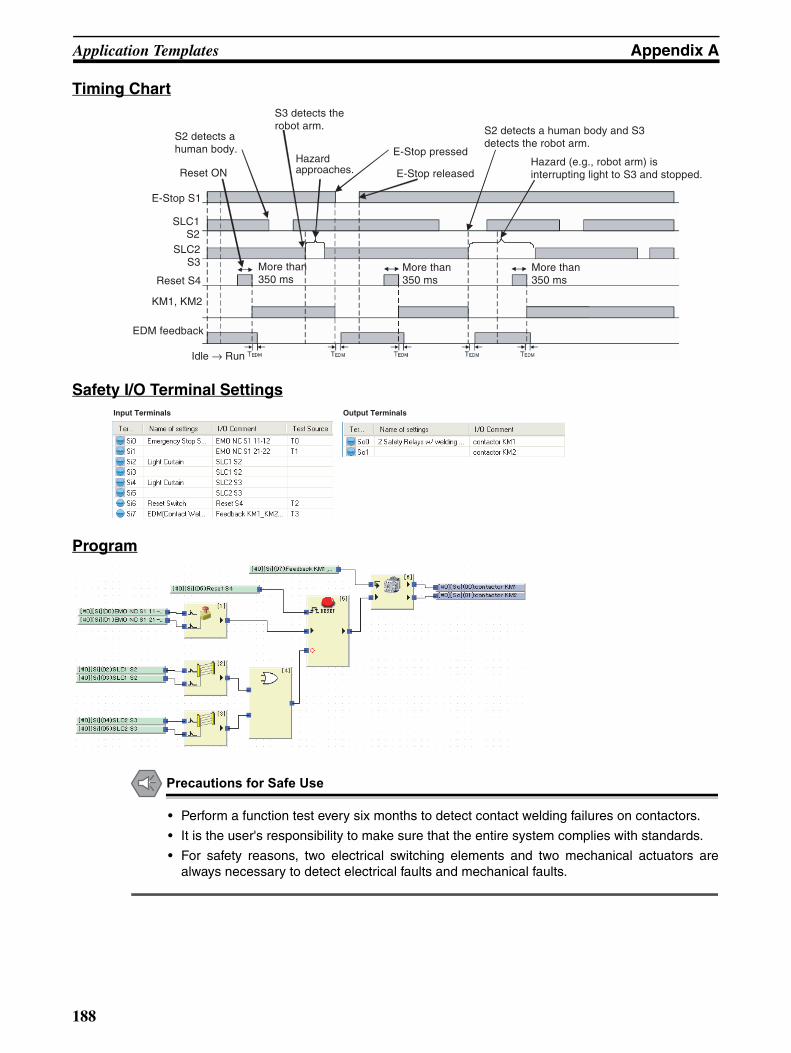
Application Templates Appendix A
Timing Chart
Safety I/O Terminal Settings
Program
Precautions for Safe Use
• Perform a function test every six months to detect contact welding failures on contactors.
• It is the user's responsibility to make sure that the entire system complies with standards.
• For safety reasons, two electrical switching elements and two mechanical actuators arealways necessary to detect electrical faults and mechanical faults.
Hazardapproaches.
S2 detects ahuman body.
Reset ON
E-Stop S1
SLC1S2
SLC2S3
Reset S4
EDM feedback
KM1, KM2
Idle → Run
More than 350 ms
More than 350 ms
S2 detects a human body and S3 detects the robot arm.
E-Stop released
E-Stop pressed
S3 detects therobot arm.
Hazard (e.g., robot arm) is interrupting light to S3 and stopped.
More than 350 ms
Input Terminals Output Terminals
188
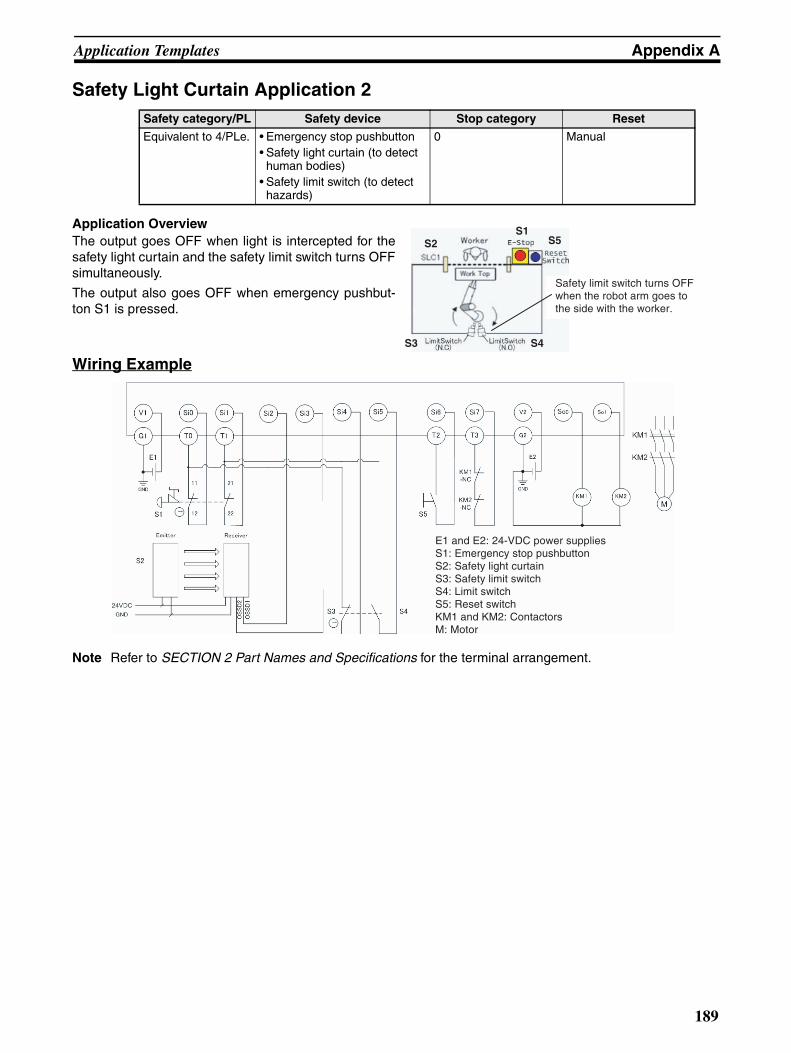
Application Templates Appendix A
Safety Light Curtain Application 2
Application OverviewThe output goes OFF when light is intercepted for thesafety light curtain and the safety limit switch turns OFFsimultaneously.
The output also goes OFF when emergency pushbut-ton S1 is pressed.
Wiring Example
Note Refer to SECTION 2 Part Names and Specifications for the terminal arrangement.
Safety category/PL Safety device Stop category Reset
Equivalent to 4/PLe. • Emergency stop pushbutton• Safety light curtain (to detect
human bodies)• Safety limit switch (to detect
hazards)
0 Manual
S1S2
S3
S5
S4
Safety limit switch turns OFF when the robot arm goes to the side with the worker.
E1 and E2: 24-VDC power suppliesS1: Emergency stop pushbuttonS2: Safety light curtainS3: Safety limit switch S4: Limit switchS5: Reset switch KM1 and KM2: Contactors M: Motor
189

Application Templates Appendix A
Timing Chart
Safety I/O Terminal Settings
Program
Precautions for Safe Use
• Perform a function test every six months to detect contact welding failures on contactors.
• It is the user's responsibility to make sure that the entire system complies with standards.
• For safety reasons, two electrical switching elements and two mechanical actuators arealways necessary to detect electrical faults and mechanical faults.
Reset ON
Idle → Run
More than 350 ms
More than 350 ms
S2 detects ahuman body.
Robot arm goes to the side of the worker.
E-Stop pressed E-Stop releasedS2 detects a human body and robot arm goes to the side of the worker.
KM1, KM2
EDM feedback
Limit switch S4
Reset S5
Safety limit switch S3
E-Stop S1
SLC1S2
More than 350 ms
Input Terminals Output Terminals
190
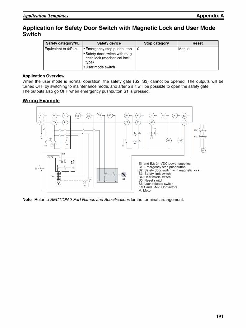
Application Templates Appendix A
Application for Safety Door Switch with Magnetic Lock and User Mode Switch
Application OverviewWhen the user mode is normal operation, the safety gate (S2, S3) cannot be opened. The outputs will beturned OFF by switching to maintenance mode, and after 5 s it will be possible to open the safety gate.The outputs also go OFF when emergency pushbutton S1 is pressed.
Wiring Example
Note Refer to SECTION 2 Part Names and Specifications for the terminal arrangement.
Safety category/PL Safety device Stop category Reset
Equivalent to 4/PLe. • Emergency stop pushbutton • Safety door switch with mag-
netic lock (mechanical lock type)
• User mode switch
0 Manual
E1 and E2: 24-VDC power suppliesS1: Emergency stop pushbutton S2: Safety door switch with magnetic lockS3: Safety limit switchS4: User mode switchS5: Reset switch S6: Lock release switchKM1 and KM2: Contactors M: Motor
191
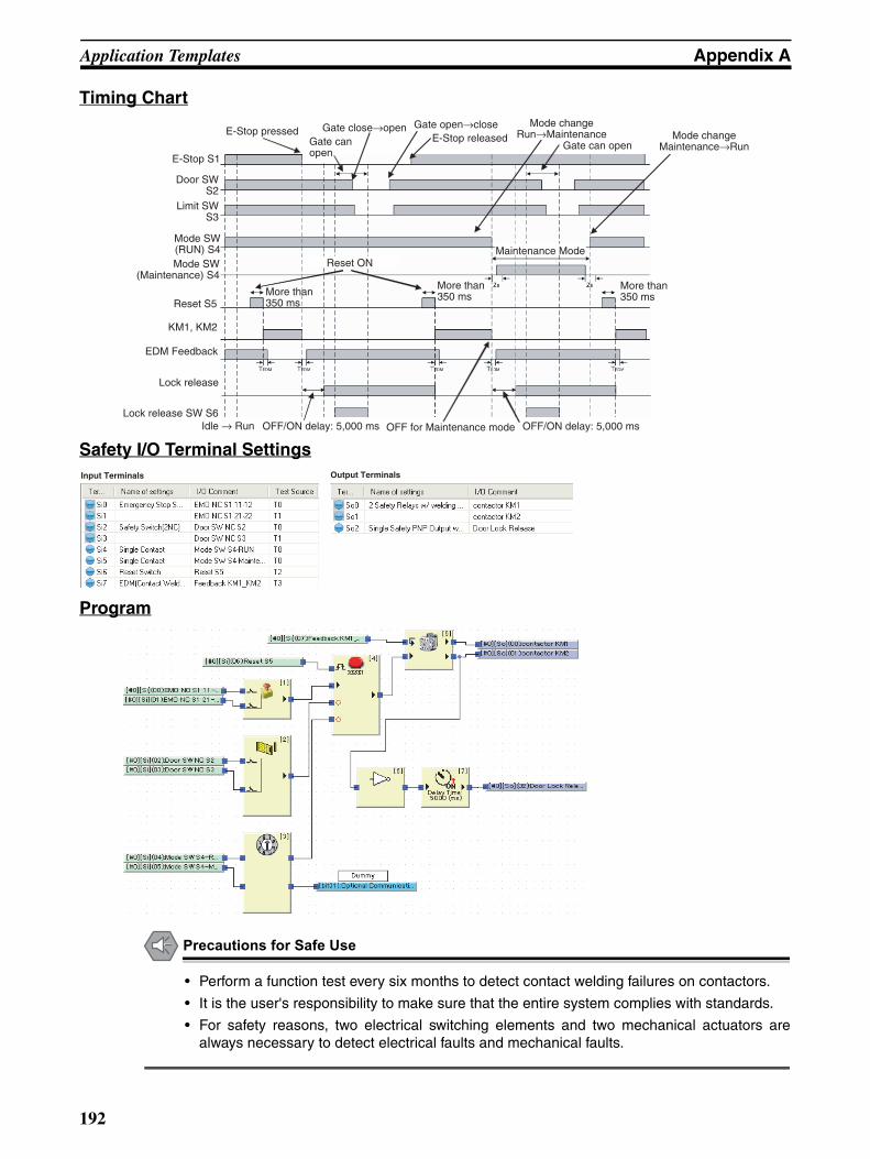
Application Templates Appendix A
Timing Chart
Safety I/O Terminal Settings
Program
Precautions for Safe Use
• Perform a function test every six months to detect contact welding failures on contactors.
• It is the user's responsibility to make sure that the entire system complies with standards.
• For safety reasons, two electrical switching elements and two mechanical actuators arealways necessary to detect electrical faults and mechanical faults.
E-Stop pressedGate can open
Gate close→open Gate open→closeE-Stop released
Reset ON
Mode changeRun→Maintenance Mode change
Maintenance→RunGate can open
Maintenance Mode
More than350 ms
More than350 msMore than
350 ms
OFF/ON delay: 5,000 msOFF for Maintenance modeOFF/ON delay: 5,000 ms
Mode SW(RUN) S4
Idle → Run
E-Stop S1
EDM Feedback
Lock release SW S6
Lock release
KM1, KM2
Mode SW(Maintenance) S4
Door SWS2
Limit SWS3
Reset S5
Input Terminals Output Terminals
192

Application Templates Appendix A
D40A Non-Contact Switch Application
Application OverviewMotor M stops when emergency stop pushbutton S1 is pressed.
Motor M is stopped by opening the connection with the safety door (D40A No-contact Switch) at S2.
Wiring Example
Note Refer to SECTION 2 Part Names and Specifications for the terminal arrangement.
Timing Chart
Safety category/PL Safety device Stop category Reset
Equivalent to 3/PLd. • Emergency stop pushbutton• D40A Non-contact Switch
0 Manual
E1 and E2: 24-VDC power suppliesS1: Emergency stop pushbutton S2: D40A Non-contact SwitchS3: Reset switchKM1and KM2: ContactorsM: Motor
More than 350 ms More than 350 ms More than 350 ms
Idle → Run
Reset ONE-Stop pressed E-Stop released
Gate close → Open Gate open → Close
E-Stop S1
Non-contact Switch S2
Reset switch S3
KM1 and KM2
EDM feedback
193

Application Templates Appendix A
Safety I/O Terminal Settings
Program
Precautions for Safe Use
• Perform a function test every six months to detect contact welding failures on contactors.
• It is the user's responsibility to make sure that the entire system complies with standards.
• For safety reasons, two electrical switching elements and two mechanical actuators arealways necessary to detect electrical faults and mechanical faults.
Input Terminals Output Terminals
194

Application Templates Appendix A
D40Z Non-Contact Switch Application
Application OverviewMotor M stops when emergency stop pushbutton S1 is pressed.
Motor M is stopped by opening the connection with the safety door (D40Z No-contact Switch) at S2.
Wiring Example
Note Refer to SECTION 2 Part Names and Specifications for the terminal arrangement.
Timing Chart
Safety category/PL Safety device Stop category Reset
Equivalent to 4/PLe. • Emergency stop pushbutton • D40Z Non-contact Switch
0 Manual
E1, E2, and E3: 24-VDC power suppliesS1: Emergency stop pushbuttonS2: D40Z Non-contact SwitchS3: Reset switchKM1and KM2: ContactorsM: Motor
More than 350 ms More than 350 ms More than 350 ms
Idle → Run
Reset ONE-Stop pressed
E-Stop releasedGate close → Open
E-Stop S1
Non-contact Switch S2
Reset switch S3
KM1 and KM2
EDM feedback
195

Application Templates Appendix A
Safety I/O Terminal Settings
Program
Precautions for Safe Use
• Perform a function test every six months to detect contact welding failures on contactors.
• It is the user's responsibility to make sure that the entire system complies with standards.
• For safety reasons, two electrical switching elements and two mechanical actuators arealways necessary to detect electrical faults and mechanical faults.
Input Terminals Output Terminals
196
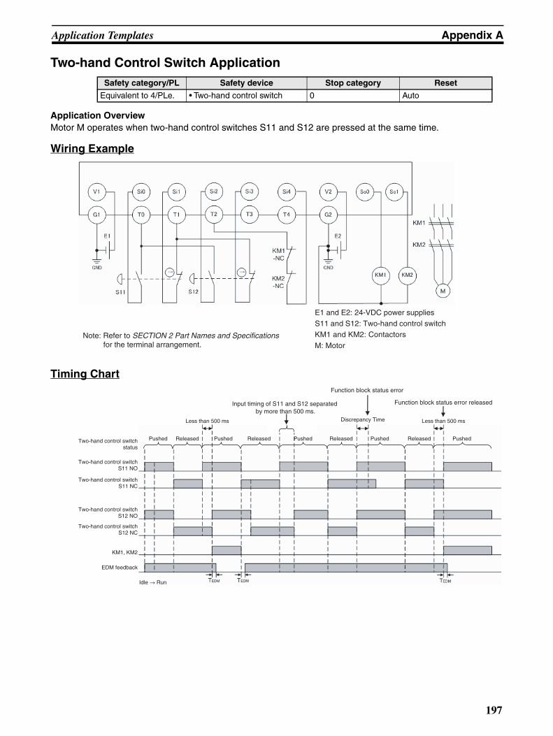
Application Templates Appendix A
Two-hand Control Switch Application
Application OverviewMotor M operates when two-hand control switches S11 and S12 are pressed at the same time.
Wiring Example
Timing Chart
Safety category/PL Safety device Stop category Reset
Equivalent to 4/PLe. • Two-hand control switch 0 Auto
E1 and E2: 24-VDC power suppliesS11 and S12: Two-hand control switchKM1 and KM2: Contactors
M: MotorNote: Refer to SECTION 2 Part Names and Specifications
for the terminal arrangement.
Two-hand control switchS11 NO
Two-hand control switchS11 NC
Two-hand control switchS12 NO
Two-hand control switchS12 NC
KM1, KM2
EDM feedback
Idle → Run
Pushed Pushed Pushed PushedReleased Released ReleasedTwo-hand control switch status
Pushed Released
Less than 500 ms
Input timing of S11 and S12 separated by more than 500 ms.
Function block status error
Discrepancy Time
Function block status error released
Less than 500 ms
197

Application Templates Appendix A
Safety I/O Terminal Settings
Program
Precautions for Safe Use
• Perform a function test every six months to detect contact welding failures on contactors.
• It is the user's responsibility to make sure that the entire system complies with standards.
• To detect electrical and mechanical failures, combine redundant semiconductor output con-tacts with redundant mechanical output devices.
• Wire the terminals correctly according to the wiring example. Connect the NO contacts onthe two-hand control switch to terminals Si0 and Si2 on the G9SP-series Controller and con-nect the NC contacts to terminals Si1 and Si3. A malfunction will occur if the connectionsare not correct.
Additional Information
• The output will not turn ON if the simultaneous operation requirement of the two-hand con-trol switch (i.e., that the operation inputs from both hands be completed within 500 ms) is notmet.
• A two-hand control switch that is set as a safety input terminal operates as a single channel.For dual-channel monitoring, use the Two-hand Control function block instead of safety inputterminals.
Input Terminals Output Terminals
198
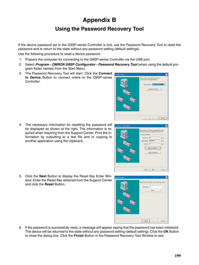
Appendix BUsing the Password Recovery Tool
If the device password set in the G9SP-series Controller is lost, use the Password Recovery Tool to reset thepassword and to return to the state without any password setting (default settings).
Use the following procedure to reset a device password.
1. Prepare the computer for connecting to the G9SP-series Controller via the USB port.
2. Select Program - OMRON G9SP Configurator - Password Recovery Tool (when using the default pro-gram folder names) from the Start Menu.
3. The Password Recovery Tool will start. Click the Connectto Device Button to connect online to the G9SP-seriesController.
4. The necessary information for resetting the password willbe displayed as shown at the right. The information is re-quired when inquiring from the Support Center. Print the in-formation by outputting to a text file and or copying toanother application using the clipboard.
5. Click the Next Button to display the Reset Key Enter Win-dow. Enter the Reset Key obtained from the Support Centerand click the Reset Button.
6. If the password is successfully reset, a message will appear saying that the password has been initialized.The device will be returned to the state without any password setting (default setting). Click the OK Buttonto close the dialog box. Click the Finish Button in the Password Recovery Tool Window to exit.
199

Using the Password Recovery Tool Appendix B
200

Appendix CCalculated Values of PFD and PFH
Calculated values of PFD and PFH of the G9SP-series Controller are given in the following tables.
These values must be calculated for the overall devices within the system to comply with the SIL level requiredfor application.
Meaning of PFD and PFH
Calculated PFD Values
Calculated PFH Values
PFD PFD stands for “probability of failure on demand.”
PFD expresses the average probability of failure of a system or device when it is demanded. This value is used to calculate the safety integrity level (SIL) of a safety system.
PFH PFH stands for “probability of failure per hour.”PFH expresses the probability of failure per hour for a system or device. This value is used to cal-culate the safety integrity level (SIL) of a safety system.
Proof test interval (years)
PFD
G9SP-N10S G9SP-N10D G9SP-N20S
0.25 8.86E-08 1.13E-07 9.71E-08
0.5 1.74E-07 2.22E-07 1.90E-07
1 3.44E-07 4.39E-07 3.77E-07
2 6.85E-07 8.75E-07 7.51E-07
5 1.71E-06 2.19E-06 1.88E-06
10 3.44E-06 4.40E-06 3.77E-06
20 6.94E-06 8.91E-06 7.62E-06
PFH
G9SP-N10S G9SP-N10D G9SP-N20S
7.80E-11 9.96E-11 8.55E-11
201

Calculated Values of PFD and PFH Appendix C
202

Appendix DVersion-related Information
This appendix describes the relationship between the unit versions of the G9SP-series Safety Controllers andthe versions of the G9SP Configurator, the ability to back up and restore data with a Memory Cassette for dif-ferent unit versions of the G9SP-series Safety Controllers, and the functions that are supported for differentunit versions of the G9SP-series Safety Controllers.
Relationship between Unit Versions of the G9SP-series Safety Controllers and G9SP Configurator VersionsThere is a correspondence between the unit versions of the G9SP-series Safety Controllers and the versionsof the G9SP Configurator. Whenever possible, use the corresponding versions.
Unit Versions of the G9SP-series Safety Controllers and Corresponding G9SP Configurator VersionsThe following table gives the versions of the G9SP Configurator that correspond to different unit versions of theG9SP-series Safety Controllers.
Note No version is displayed in the hardware settings of the G9SP-series Safety Controller for versions 1.00and 1.10 of the G9SP Configurator.
Non-corresponding G9SP-series Safety Controller and G9SP Configurator VersionsThe following operation will occur when the version of the G9SP Configurator does not correspond to the unitversion of the G9SP-series Safety Controller.
Using an Older G9SP Configurator VersionIf the version of the G9SP Configurator is old, you will not be able to online and to Configure the G9SP-seriesSafety Controller from the G9SP Configurator.
Example: G9SP-series Controller with unit version 2.0G9SP Configurator version 1.10Version 1.10 of the G9SP Configurator supports unit version 1.1 of the G9SP-series Safety Control-lers, but it does not support unit version 2.0. If you use a G9SP-series Safety Controller with unitversion 2.0, use G9SP Configurator version 2.00.
G9SP-series Safety Controller G9SP Configurator
Model Unit version Corresponding version Version displayed in hardware settings
G9SP-N10S Ver. 2.0 Ver. 2.00 Ver. 2
Ver. 1.1 Ver. 1.00/Ver. 1.10/Ver. 2.00 Ver. 1 (See note.)
Ver. 1.0
G9SP-N10D Ver. 2.0 Ver. 2.00 Ver. 2
Ver. 1.1 Ver. 1.00/Ver. 1.10/Ver. 2.00 Ver. 1 (See note.)
Ver. 1.0
G9SP-N20S Ver. 2.0 Ver. 2.00 Ver. 2
Ver. 1.1 Ver. 1.00/Ver. 1.10/Ver. 2.00 Ver. 1 (See note.)
Ver. 1.0
203

Version-related Information Appendix D
Using a G9SP-series Safety Controller with an Older Unit VersionIf the unit version of the G9SP-series Safety Controller is old, select the hardware that matches the version ofthe connected Controller on the Hardware Settings Dialog Box on the G9SP Configurator.
Example: G9SP-series Controller with unit version 1.1G9SP Configurator version 2.00Version 2.00 of the G9SP Configurator supports G9SP-series Safety Controllers with unit version1.1. You can perform configuration for the range of functions that are supported by unit version 1.1of the G9SP-series Safety Controllers.
G9SP Configurator Configuration Data CompatibilityYou can use configuration data that was created on G9SP Configurator version 1.00 or 1.10 on G9SP Configu-rator version 2.00. You can also change configuration data that was created for unit version 1.1 of the G9SP-series Safety Controller to configuration data for unit version 2.0 of the G9SP-series Safety Controllers by set-ting the unit version to 2.0 for the same model of G9SP-series Safety Controller on the Hardware Settings Dia-log Box on G9SP Configurator version 2.00.
Precautions for Correct Use
You cannot convert configuration data that was created for unit version 2.0 of the G9SP-seriesSafety Controllers for use on G9SP-series Safety Controllers with unit version 1.1.
Unit Version Operations on the G9SP ConfiguratorWhether G9SP Configurator operations are possible for different unit versions of the G9SP-series Safety Con-troller is given in the following table. Use this table to confirm applicability if you want to reuse existing configu-ration data. In all cases, the G9SP-series model must be the same.
Note (1) Refer to Function Additions and Changes for Unit Version Upgrades in the appendices for informa-tion on new functions.
(2) If you upload the data using online operations, the hardware setting for the version (version 1 or 2)will match the unit version of the connected G9SP-series Safety Controller.
(3) Versions 1.00 and 1.10 of the G9SP Configurator do not support G9SP-series Safety Controllerswith unit version 2.0. Therefore, online operations cannot be performed.
(4) Online operations cannot be performed because the configuration uses new functions that are notsupported by unit version 1.0 or 1.1 of the G9SP-series Safety Controllers. If the configuration ischanged so that new functions are not used, online operation will become possible.
G9SP Configurator
version
Configuration on G9SP Configurator Unit version of G9SP-series
Safety Controller
Online operations
Hardware settings
New functions (See note 1.)
Downloading (See note 2.)
Other online operations
Ver. 1.00/Ver. 1.10 (Ver. 1) Not used. Ver. 1.0/Ver. 1.1 Executable Executable
Ver. 2.0 Not executable (See note 3.)
Not executable (See note 3.)
Ver. 2.00 Ver. 1 Not used. Ver. 1.0/Ver. 1.1 Executable Executable
Ver. 2.0 Executable Executable
Ver. 2 Not used. Ver. 1.0/Ver. 1.1 Executable Executable
Ver. 2.0 Executable Executable
Used. Ver. 1.0/Ver. 1.1 Not executable (See note 4.)
Not executable (See note 4.)
Ver. 2.0 Executable Executable
204

Version-related Information Appendix D
Relationship between the Unit Version of the G9SP-series Safety Controller and Backing Up/Restoring Data Using a Memory CassetteThe following tables tell when you can use the G9SP backup function to save the configuration data in aCP1W-ME05M Memory Cassette and then restore the data to a different G9SP-series Safety Controller. Referto SECTION 11 Backup and Restore Data Using Memory Cassette for details on the backup/restore functions.
Unit Versions and Backing Up DataTo back up data from a G9SP-series Safety Controller, you save the G9SP-series configuration data in a Mem-ory Cassette. The previous contents of the Memory Cassette will be overwritten. Depending on the configura-tion, the backup data will be as described in the following table.
Note Refer to Function Additions and Changes for Unit Version Upgrades in the appendices for information onnew functions.
Unit Versions and Restoring DataThe following table tells when you can restore backup data that was saved in a Memory Cassette from aG9SP-series Safety Controller for different unit versions of G9SP-series Safety Controllers.
Note The data cannot be restored because the backup data uses new functions that are not supported by unitversion 1.0 or 1.1 of the G9SP-series Safety Controllers.
Function Additions and Changes for Unit Version UpgradesThis section describes additions and changes to supported functions for upgrades to the unit version of theG9SP-series Safety Controllers.
Additions and Changes to Functional SpecificationsThe following table gives the unit versions of the G9SP-series Safety Controller and the versions of the G9SPConfigurator for each addition and change to the functional specifications.
Unit version of G9SP-series Safety Controller
New functions (See note.)
Backup data on Memory Cassette
Ver. 1.0/Ver. 1.1 Not used Data that is compatible with version 1.0 or 1.1
Ver. 2.0 Not used Data that is compatible with version 1.0 or 1.1
Used. Data for version 2.0
Backup data (restore data) in Memory Cassette
Unit version of G9SP-series
Safety Controller
Executable?
Data that is compatible with ver-sion 1.0 or 1.1
Ver. 1.0/Ver. 1.1 Executable
Ver. 2.0 Executable
Data for version 2.0 Ver. 1.0/Ver. 1.1 Not executable (See note.)
Ver. 2.0 Executable
Function Addition/change
Unit version
G9SP Configurator
version
Reference
Safety Input functions
Setting multiple systems of OMRON Single Beam Safety Sensors
Addition Ver. 2.0 Ver. 2.00 2-1-5 Safety Inputs
Serial communi-cations
Setting the baud rate on a DIP switch on the front panel of the G9SP-series Safety Controller when using an RS-232C serial communications port (CP1W-CIF01)
Addition Ver. 2.0 Ver. 2.00 2-1-1 Part Names and Indicators
205

Version-related Information Appendix D
206

Index
Bbacking up data, 162
building program, 85
Cconfiguration ID, 167
configuration lock, 143
configuration unlock, 144
cycle time, 53, 86
DDevice Monitor, 148
device password, 88, 137
diagnosis, 28, 36
discrepancy time, 29
dual channel evaluation, 29
Dual Channel Mode, 36
Eerror log, 150
FForce Mode, 155
force-set/force-reset, 155
II/O comments, 82, 84
I/O tags, 84
input filters, 31
JJump tag, 85
MMemory Cassette operations, 160
OOFF delay, 31
ON delay, 31
operation log, 151
Ppages, 85
parameter password, 88
PFD/PFH, 201
Rreaction time, 53
reports, 87
resetting, 136
restore prohibition, 164
restoring data, 164
returning to the out-of-box configuration, 136
SSafety Input terminals, 82
Safety Output terminals, 82
safety response performance, 53
safety signature, 167
safety validation testing, 158
single/dual setting, 29, 36
system settings, 86
TTest Mode, 29
test pulse evaluation, 28, 35
test source, 28
UUnit Conduction Time, 150
unit configuration, 81
user testing, 158
user-defined function blocks, 85
207

Index
Vverification, 134
WWatch Window, 153
208

Revision History
A manual revision code appears as a suffix to the catalog number on lower left corners of the front and backcovers of the manual.
The following table outlines the changes made to the manual during each revision. Page numbers refer to theprevious version.
Revision code Date Revised content
01 June 2010 Original production
02 September 2010 Added D40Z No-contact Switch, added descriptions, and corrected mistakes.
03 April 2011 Added information on Support Software versions and the S Mark.Added descriptions and corrected mistakes.
04 June 2014 Added information on unit version upgrade.Corrected mistakes and added descriptions.
Cat. No. Z922-E1-04
Revision code
209

Revision History
210


Authorized Distributor:
In the interest of product improvement, specifications are subject to change without notice.
Cat. No. Z922-E1-04 0614
© OMRON Corporation 2010 All Rights Reserved.
OMRON Corporation Industrial Automation Company
Regional HeadquartersOMRON EUROPE B.V.Wegalaan 67-69-2132 JD HoofddorpThe NetherlandsTel: (31)2356-81-300/Fax: (31)2356-81-388
Contact: www.ia.omron.comTokyo, JAPAN
OMRON ASIA PACIFIC PTE. LTD.No. 438A Alexandra Road # 05-05/08 (Lobby 2), Alexandra Technopark, Singapore 119967Tel: (65) 6835-3011/Fax: (65) 6835-2711
OMRON (CHINA) CO., LTD.Room 2211, Bank of China Tower, 200 Yin Cheng Zhong Road, PuDong New Area, Shanghai, 200120, ChinaTel: (86) 21-5037-2222/Fax: (86) 21-5037-2200
OMRON SCIENTIFIC TECHNOLOGIES INC.6550 Dumbarton Circle Fremont CA 94555 USATel: (1) 510-608-3400/Fax: (1) 510-744-1442