fundamentals of mechanical drawing - nj7p 1-1050 24-mar-43 scribd.pdffundamentals of mechanical...
TRANSCRIPT
I
•
, TM 1- 1050
MANUAL
FUNDAMENTALS OF MECHANICAL DRAWING
March 24, 194'3
TECHNICAL llANUAL ) No. 1- 1000
• • • Tr:i.\ \\050
r\lq~
** TM 1-1050 ,
WAR DEPARTMENT, WUHUfaroll', Marcb24, l~
FUNDAMENT.ALS OF MECHANICAL DRAWING
P. ralt&l'bi SECTION I. GeneraL_______________________________________ 1 II. Equipment and materials __________ ______ :.. ______ 2-16
ill. Lettering and lines ____________________________ 17- 18 IV. Geometric oonstructions.: __ _________ ____________ 19-34
V. Orthographic projection ________________________ M-37 VI. Pictorial drawing ______ __ ______________________ 3S-42
VII. Sectional views 9.Dd threaded parts ______________ _ 43-44 VIII. Scales, dimensions, and notes ____________________ 45-47 ~. Technical sketching___________________ ___ __ ____ "48 X . Sheet metal drafting _________ ________ _________ _ 49-52
XI. Representative working drawiugs___________ ____ _ ~
SF.CTION I •
GENERAL
Pan. ..... Pb ()eneral ___ ~__________________________________________________________ _ 1
1. General.--<l. (1) The design, const ruction, and repair of machines or structures involve II. mass of detail with respect to specific parta A complete written or oral description of detailed units would necessitate a lengthy, complex discussion which would tend to confuse and retard the progress of the workman. It is more efficient to present the various design features in the form of a drawing, showing various views, 80 that details of construction may be readily interpretOO. The use of a drawing containing dimensions, notes, ew., for further simplification, presents to the workman clear, concil!e information.
(2) A drawing is made with the aid of instruments and other equip.. ment, in which form it is known as a m~hanical drawing, or it is made as a freehand skeU;h. The u ocution of such drawings requires skill, accuracy, and an understanding of the subject matter. In the various industries, practices may vary as to the manner of presentation of information in meehanical drawings, but the manner of e.xeeu-tion of such drawings is common· to all; ~.
,1I1811S' 13 1 ( 1 o,'gir I< UNM~\fTY Of (AllfORNIA
•
1
! I -
(
•
• • • Or , If. UN I ill \!TY Qf t.l.l.ll(lAAIA
•
FUNDAMENTALS OF MECHANICAL DRAWING • (3) The purpoae of this manual is to lamiliariUl the student me
chanic with the basic principles of mechanical drawing and genel'1l.l practiOOll ~levant thereto. Only subject matter considered e8IIential for use in basic OOUnJeS in mechanical drawing bas been included. TablM of limits, clllfWe8 of fits, standard dimensions of threads, etc., have been omitted, as such subject matter more appropriately pertains to the more advanced and specialized COUrge8 in drafting. When the need ari!lell for infonnation of this type, reference should be made to handbooks oontaining such tables.
b. As II rule, the use of original dl'1l.wings would be impractical. The circulation of the drawing would be limited and would soon be destroyed or rendered illegible as a re!rult of wear. Therefore, dupli . cates are prepared for use in the work of production, maintenance, ek:. The drawing is first tra.ced in ink or pencil, using translucent cloth or paper ; or in !!Orne instances, the originl\l drawing is executed on tmcing paper. The drawing may be duplicated. by eJ:poeing it to an intense light while in OOlltact with an eepeciaUy prepared sensitized paper. Aher uposure to the light, the eJ:poeea paper is treated with certain chemicals which develop the im~ There are numerous printing p~ and types of paper which may be used for drawing reproduction. The final product or print may have white lines on a blue background, white line!! on a brown background, black lines on a white background, or red lines on a white background, depending upon the procew and type of paper used. Blueprints, V Ml Dyke prints, Oolid prints, and photostat prints are BOrne of the mOlit wmmon I.ypes of reproductions.
c. (1) There apparently is little uniformity in the size of drawings. III many instances the size of the sheet is selected to suit the object 10 be drawn. Often, however, the standard letter-size abeet of 8* by 11 illches is used for small drawings. For larger drawings, multiples of this size, as shown below, are used. This range fRdlitates folding prints into suitable sizes for filing in letter-size filing cabinet&. The 42-inch size is an eJ:oeption, but is UBed for PUrpo80l:l of ecol\omy.
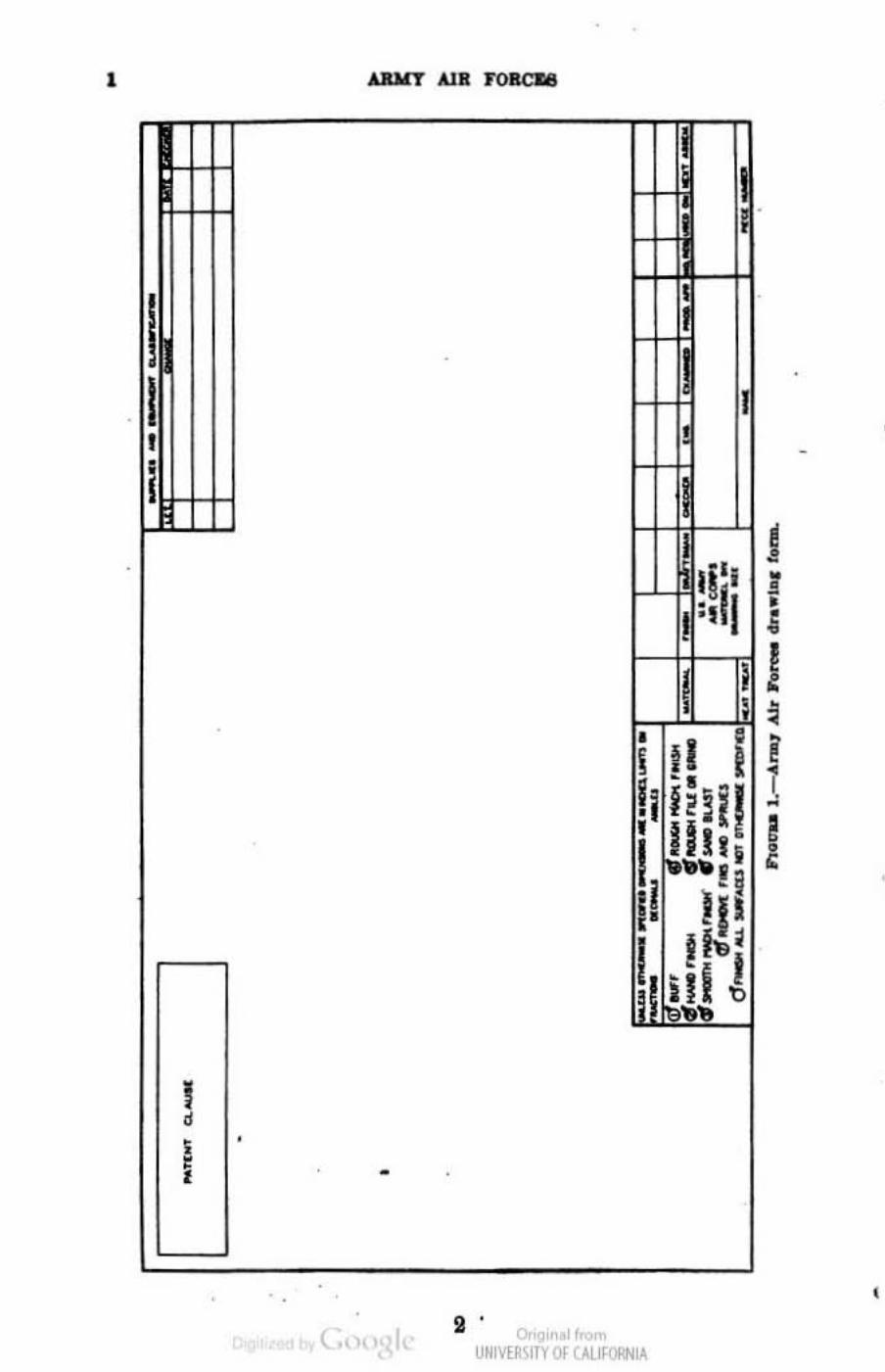
(2) In addition to dimensions and notes, certain other data are associated. with a drawing. Theile data ulUally include the title, number, scale, material, finish, changes, patent dawn, ete., set out in blocks. Figure 1 shows the arrangement of such data on a drawing form used by the Army Air Forees..
d. The subject matter and illustrations contained in this manual,
• Or'gir I.UNM~\fTY Of (AllfORNIA
ARMY AlR rORCI'.8
with reepect to line work, arrangement of vie~ symbols., sectional views, dimensioning, and acrew thread repreeentation, is generally • in a.ocordanoe with principlee approved by American Standards ApI>
ciation in publication entitled ".American Standard Drawings and Drafting Room Practice. .. •
SIlCTION n EQUIPMENT AND MATERIALS I
Par.".apb. ])rI~Dr boArd_____ __ __ _________________________________________________ 2 Paper and ~lotb____________ _ ___________________________________________ 8 PeDd1a _ ________________________________ ______________ _ ________ " Eraeers_________ ____________________ __________________________________ 6 T .tIQu ....... __ -:" ____________ ~------------ - - -- ----- - -------- ----- ________ __ Trllllglee __ _________________ ~ _______ _ _ _ _ _ __ _ _ __ _ __ __ __ . ________ ______ _
Irl"J.'«Olar ~----------- - --- -------- --- -- - - -- -- - ---------- - ---- ------
• 7 8
Trlllll"Diu _18..____ _____ _______ _____ _ _________ __ ____________________ 9 f'wt~let<X _> ____ _ ____ ______ _ _ ____ ~____________________ ____________ 10
Rul~ pen ____________ __ _________ ~--- ------------------_________ _______ 11 Letterlllr PI' Il~ __ ____ ____ ___________ =____ _ ___ __ _ ___ __ __ __ _ __ _ ___ ___ ___ 12 COIllPIII_______________________________________________________________ 18 DI"lders ______ _______________________ ::_____ __________________________ 14 ~ ·~Ilt _____ __________________ ________________________ _ _____ 16 Care III equlpme:ut _________ ________ _____________________________ ______ 16
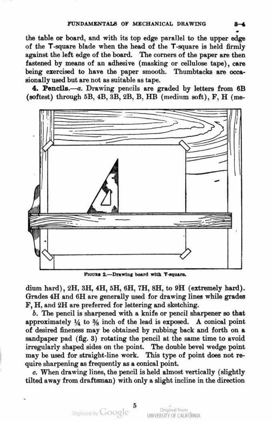
2. Drawing boai'd.-A drawing hoard or table ill used to provide a flat, smooth surface for the paper while the drawing is being m&cie, and also provides a straight edge for guiding the T -square. A typidI drawing board, with T-gquarn and drawing piper in place, is sbo1VD in figure 2.
3. Paper and clotlr.~. Drawing paper is available in a variety of grades, in shoot!! or rolls., in colO1"8 of white, cream, or bu1I'. For general pencil work, a paper with slight grain and good e~ing qualities is desirable. Thin, toughl translucent paper which is transparent with closa contact ill used to trace copies in pencil or ink. TraCing paper is also used for original pencil drawings. Fine linen cloth, treated !flO as to make it translucent and smooth, ia generally used for ink tracing. The dull side of the cloth is used and, prior to inking, the surface is lightly sprinkled and rubbed with powdered chalk or soapstone. Where an erasure has been made, the cloth is again treated with chalk or soapstone.
b. The paper should be placed with one edge near the left edge of
• P<ormlaoloa ....... teIl..,. ~ ... " 8oc1et,- 0' !II~lI.al"l EDKI_ro. 'TIle .. bJee\: ",.tut.1Id UluotnUoal Oil .- o r OqulpllIeIIl Ir<I ..... d 11p011 111I0rm0tlGQ
.... utolae<l 111 ""b1l .. U011 " U .. aDd Cue 01 Dr.-.!nlJ l ... trumouto, ~ blll:_ J)I~ 00.,
.\tb tIIIl. permLoatoll..
o,'gir 01",,", UNM~\1TY Of (AllfORNIA
TUNDAMWTALB OF MECHANICAL DRAWING .....
• the table or board, and with its top ed~ parallel to the upper ~ of the T-square blade when the head of the T-square is held firmly against the left edge of the board. The corners of the paper are then fastened by mearul of an adhesive (mllSlring or cellulose tape), care being exereised to have the paper Bmooth. Thumbtacks are OOC&
aionally used but are not as suitable as tape. 4. Pencll8_-a. Drawing pencils are graded by lettere from 6B
(eoftest) through liB, 4B, aB, 2B, B , HB (medium 90ft) , F, H (me-
-
dium hsrd), 2H, 3H, 4H, 6H, 6H, 7H, 8H, to OR (enremely hard). Orndes 4H and 6H sre generally used for drawing Iinel!l while grades F , H , and 2H are preferred for lettering and sketching.
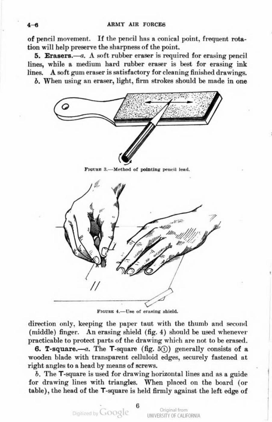
b. The pencil is sharpened with a knife or pencil sha.rpener so that approximately * to % inch of the lead is exposed. A conical point of desired fineness may be obtained by rubbing back and forth on &
sandpaper pad (fig. 3) rotating the pencil at the same time to avoid irregularly shaped sides on the point. The double bevel wedge point may be used for straight.line work. This type of point does not require sharpening as frequently as a conical point.
c. When drawing lines, the pencil is held almost vertica.lly (slightly tilted away from draftsman) with only a slight incline in the direction
, ( .. Or'gir II< ,
UNM~\fTY Of C'J.lfORN lA
ARMY AIR FORCU
of pencil movement. If the penci ! hils II conin! point, fnlquent rota· tion wil! help preserve the sharpness of the point.
5. Erasers.--<l. A soft rubber eraser is requ ired for erw;ing ~ncil lines, while a medium hard rubber eraser is best for erasing ink lines. A soft gum eraser is SIltisfttctory for cleaning fini shed drawings.
b. ' Vhen using an eraser, light , firm strokes should be made in one
r '8\;" . - " "'
II
dil'flCl ion only, kP.l!ping the plI.pl'r taut wit h the thumb and !It.>o.;,m,[ (middle) finger. An erasing shield (fig. 4) should he used whcnevl'l" pIllcticable to protect part.\! of the d rawing which 1I 1~ not to be ensOO.
6 . T·squar e.--a. The T.square ( fig. 50) !,"Cncnlly consisb! of a wooden blade with transparent ceUuloid edges, seeurely fastened at right angles to a head by !!lellns of IICrews.
b. The T-square is used for d rawing horizontal lines II.nd as a guide for drawing lilies with triangles. When plnood on the board (or table), the head of the T-square is held fi nnly against the left edge of
G ( ~ " UNIVERSITY Of CALI fORNIA
I I I
,
FUND.u.u:NTALS OF lIECHANlCAL DRAWINO &-1
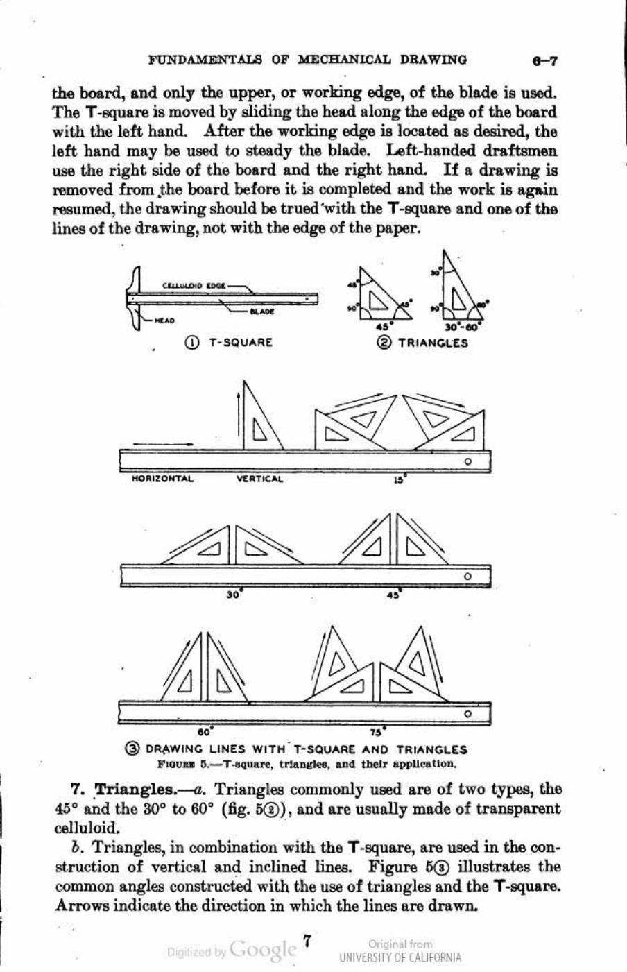
the board, and only the upper, or worlring edge, of the blade iB ueed. The T-square is moved by sliding the head along the edge of the board with the left hand. AfWr the working edge is located as desired, the left hllnd may be used tQ steady the blade. Left-handed draftsmen use the right side of the board and the right hand. If a drawing is removed from .the board before it is oompleted and the work is agaill resumed, the drawing should be trued with the T-square and one of the lines of the drawing, not with the edg6 of the ps.per.
~.;, SO'-eo
CD T-SQUARE ® TIUANGLES
"
~ " @ DR"WING LINES WITH ' T-SQUAR( AND TRIANCUS
1'...., .. ~.-T-equ.,.." trlanrlM, an4 tl>elr appU ... 1I0ll.
7 • . Trianglea.-(l. Triangles commonly used are of two types, the 4lj G and the 30G to 60° (fig.ll@),andareusuBtlymadeof transparent celluloid. .
b. Triangles, in oombination with the T -square, are used in the oonstruction of vertical an~ inclined linea. Figure 6@ illustrates the common angles constructed with the use of triangles and the T.squaro. Arrows indicate the direction in which the lines are drawn.
( 7 Or'gir I.UNM~\fTY Of (AllfORNIA
ARJ4T Ala FORCK8
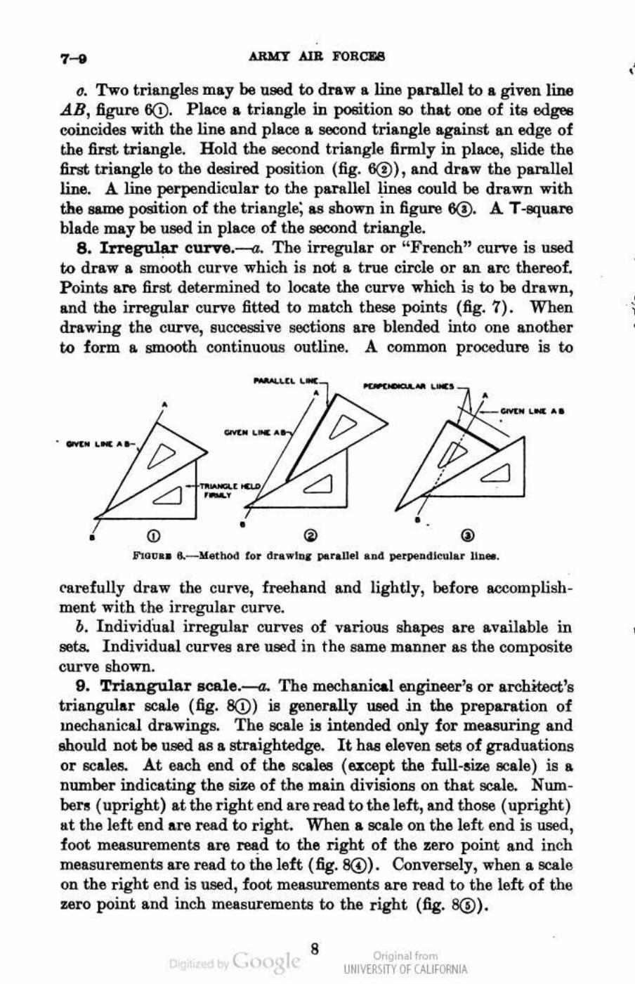
(J. Two triangles may be used to draw a line parallel to a given line A.B, figure 60. Place a triangle in position 90 that one of ita edget:l coincides with the line and place a second triangle against an edge of the first triangle. H old the 86C0nd triangle finnly in place, slide the first triangle to the deeired poeition (fig. 6@),and draw the panLllel line. A line perpendicular to the parallel linllll could be drawn with the same position of the triangle; f.l'l shown in figure 6@. A.. T -square blade may be used in place of the aeoond triangle.
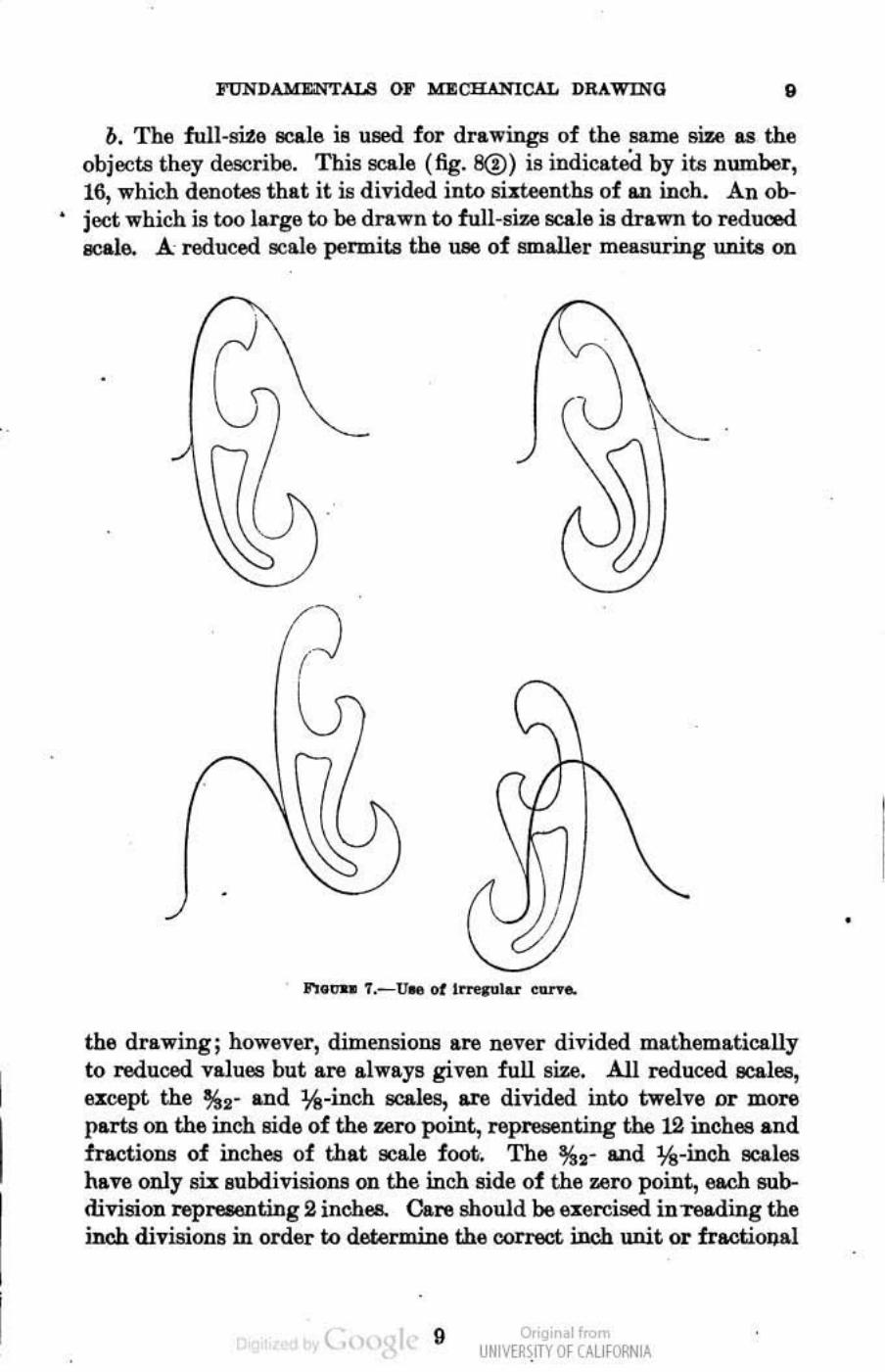
8. Irregular curve.---a. The irn.!gular or "French" curve is used to draw a smooth curve which is not a true circle or an arc thereof. Pointa are first determined to locate the curve which is to be drawn, and the irregular curve fitted to match these points (fig. 7). When drawing the curve, successive sections are blended into one another to fonn a smootb continuous ouUine. A common procedure is to
r 7" .. ' ....
• <D .,
-,",GO •• a.- Method rOt draw!lI, Il/Iralle! .!>d pe"",,""IO\Ilar II~ ...
('Brefully draw the curve, freehand and lightly, before accomplishment with the irn.!gular curve.
o. Individual irn.!gular curves of various shapes are available in sets. Individual curves are used in the same manner as the composite curve shown.
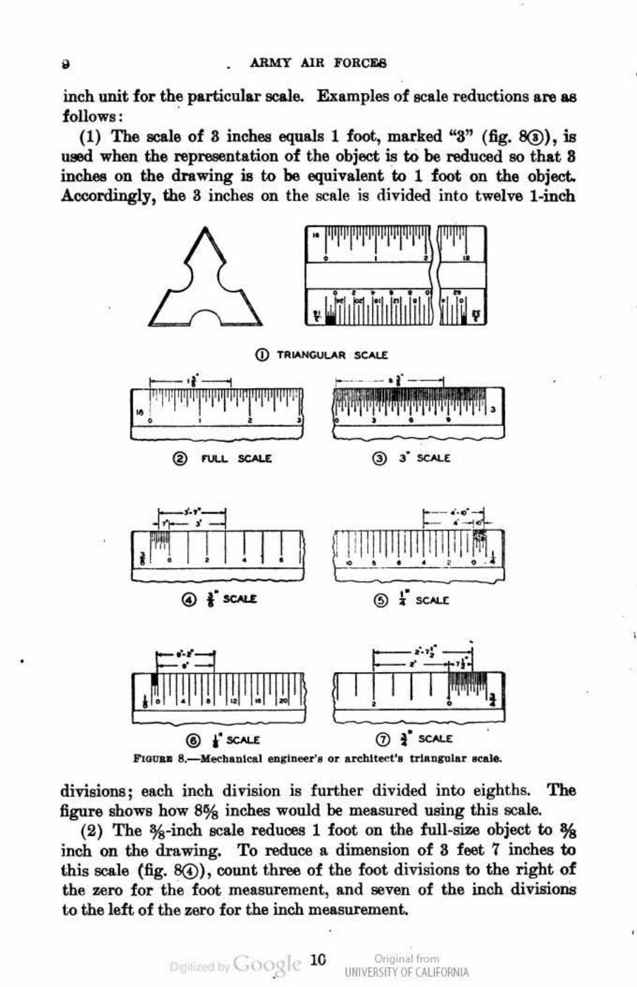
9. Triangular seale.---a. The mechanical engineer's or a.rc.hitoot's triangular 8C11.ie (fig. SCV) is generally med .in the preparation of mechanical drawinge. The scale is intended only for measuring and should not be used as a straightedge. It haa eleven 86t& of graduations or llCales. At each end of the sca.l615 (e:l:OOpt the full-size scale) is a number indicating the size of the main divisions on that scale. Numbel"!! (upright) at the right end are read to the left, and those (upright) ILt the left end are read to right. When a scale on the left end is used, f oot measurements are read to the right of the zero point and inch measurements are read to the left (fig. B<D). Conversely, when a 9C&le on the right end is used, foot measurements are read to the left of the zero point and inch measurements to the right (fig. 8@).
( 8 o,'gir I<
UNM~\fTY Of (AllfORNIA
, •
, , ,
•
FUNDAMI'oNTAL8 0 .. MECHANICAL DRAWING • b. The full-site we is used for drawings of the same size .... the
objects they describe_ This scale (fig. 8(!) is indicated by its number, 16, which denotes that it is divided into siIteenths of an inch. An ob-
• ject which is too larg!:! to be drawn to full-size scale is drawn to reduced scale. A reducfJd scale pennits the U8e of smaller measuring unita on
'\
'\ c:
)
(\ ,,\
.F--
.., .. "". T.-Uoe Of I ......... lu Olln'"
the drawing; however, dirnensioIlB are never divided mathematically to reduced values but are always given full size. All reduced scales, ucept the %2' and lk-inch scales, are divided into twelve or roOJ:'l:l parts on the inch side of the zero point, representing the 12 inches and fractioD.8 of inches of that scale foot. The %,- and lk-inch acales have only si:t BubdivisioIl! on the inch side of the zero point, each subdivision J:'I:Iprwnting 2 inche& Care should be el:ercised inTe&ding the inch divisions in order to determine the correct inch unit or fractional
( .. • o,'gir 01",,",
UNM~':fTY Of C'.llfORNlA
•
,
• ARMY AIR I'OHe m
inch unit for the particular scale. Examples of scale reductions are as follows : '
(1) The aca1e of 3 inches equals 1 foot, mlU'ked "3" (fig. 80), is used when the repre86ntation of the object is to be reduced 110 that 8 inehe8 on the drawing is to be equivalent to 1 foot on the object. Aooordingly, the a inchllB on the !!CRle is divided into twelve l ·inch
® n.u.. v£·r
r=- ' ."
@ .. SCMr @ f se",r
® .. sc·" sc.o,r
J'to ..... 8.-M,,"' •• alcal en.c1a ... •• or uclIl.oet'. trl ...... l.o.r ocak
divisions ; each inch division is further divided into eighths. The figure shows how 8% inches would be measured using this scale.
(2) The %-inch lIC&le reduces 1 foot on the full-size object to % inch on the dra.wing. To reduce a dimension of 8 feet 7 inches to this scale (fig. 8@) ,countthree.ofthe foot divisions to the right of the zero for the foot measurement, and seven of the inch divisioll6 \..0 the left of the Z6I'Q for the inch measuremenL
( 10 Or'gir I< UNM~\fTY Of (AllfORNIA
,
•
FUNDAMEl.'"TALS 0,. MJl:CHANICAL DRAWING &-11
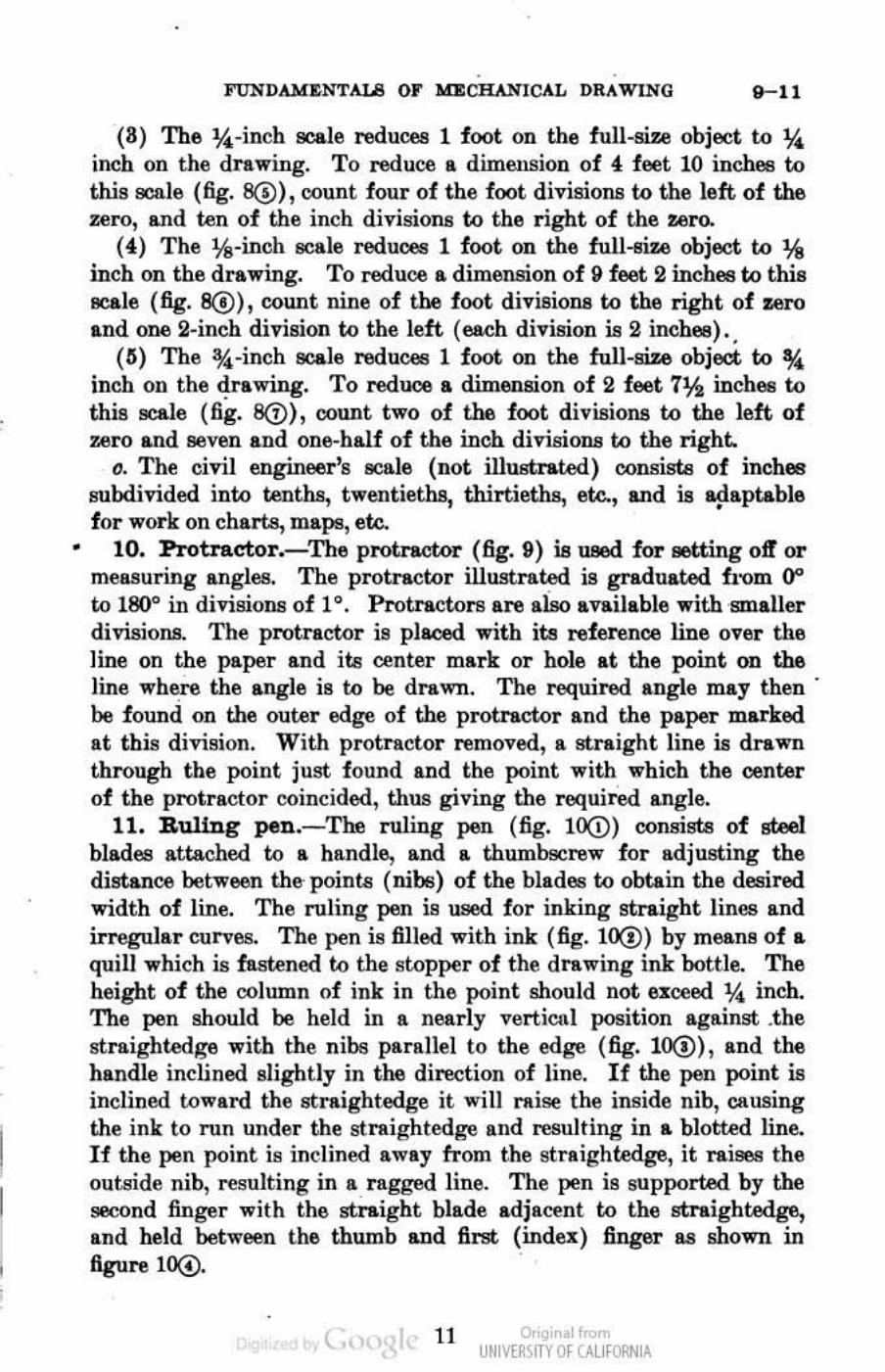
(8) The %-incb _Ie reduces 1 foot OD the full-size object to % inch on the drawing_ To reduce a dimension of 01, feet 10 inches to this seale (fig. 8@),count four of the foot divisions to the left of the zero, and ten of the inch divisions to the right of the zero.
(01,) The t,S-inch scale reduces 1 foot on the full-eiz.e object to % inch on the drawing. To reduce II. dimension of 9 feet 2 inches to this _Ie (fig. 8(!), count nine of the foot divisioll8 to the right of zero and one 2-inch division to the left (each division is 2 inches) ..
(G) The *-inch _Ie reduces 1 foot on the full-size object to * inch OD the drawing. To reduce a dimension of 2 feet 7JA inch68 to this scale (fig. 8(!), count two of the foot divisioll8 to the left of zero and Beven and one-half of the inch divisions to the right.
0. The civil engineer's 8Cale (not illustrated) oonsista of inches subdivided into tenths, twentieths, thirtieths, etc., and is Iljiaptable for work on charts, maps, etc.
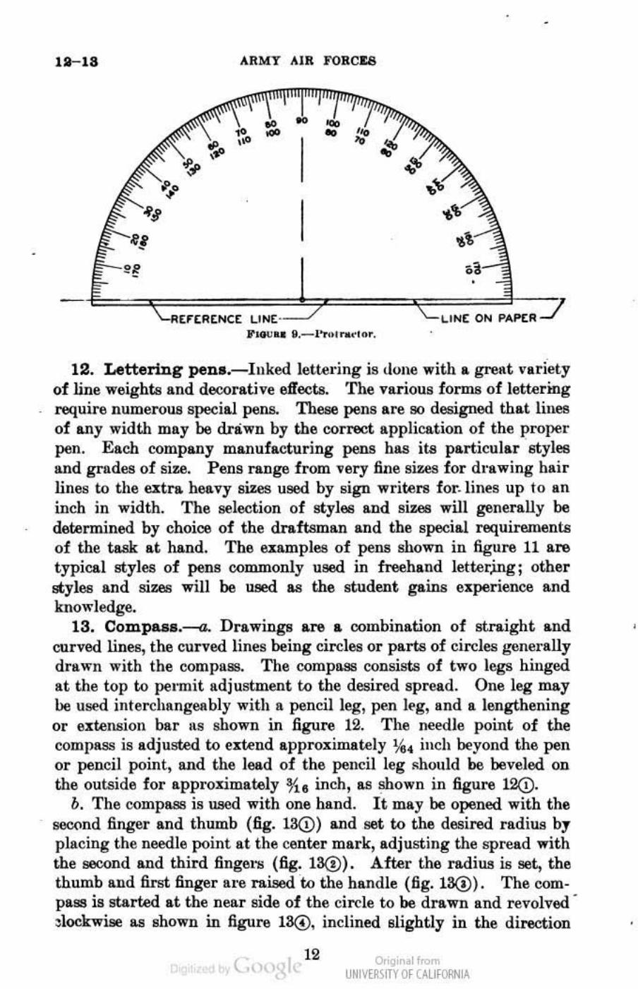
10. Protractor.-The protractor (fig. 9) is used for setting otT or mell8uring angles. The protractor illustrated is graduated from 0" to 180° in divisioll8 of 10. Protractors are alSo available with smaller divisions. The protracWr is placed with its reference line over the line on the paper and its center mark or hole at the point on the line wh~ the angle is to be drawn. The required angle may then' be found on the outer edge of the protractor and the paper marked at this division. With protractor removed, a straight line is drawn through the point just found and the point with which the center of the protractor coincided, thus giving the required angle.
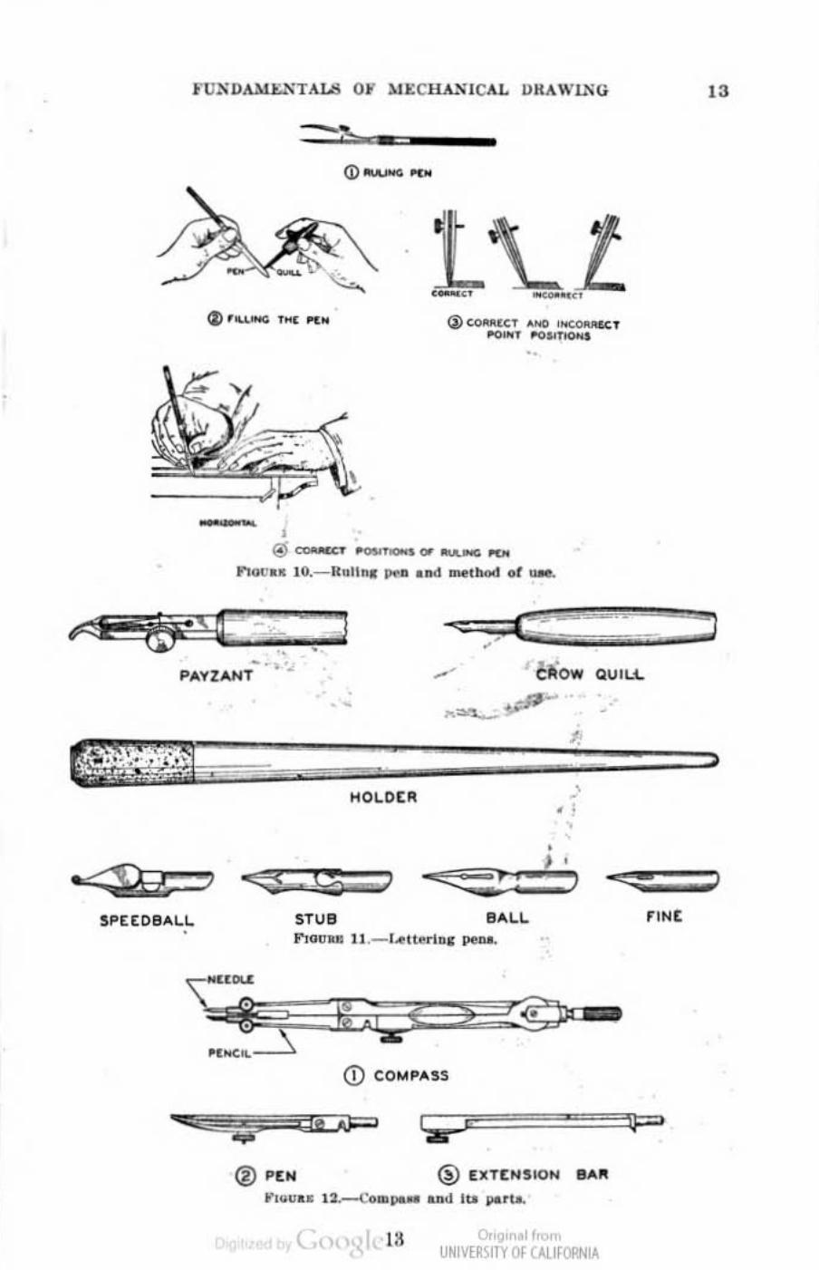
11. RuUn g pen.- The ruling pen (fig. 10(i) consists of steel blades attached to a handle, snd a thumbscrew for adjusting the distance between the'points (nibs) of the blades to obtain the desired width of line. The ruling pen is used for inking straight lines and irregular curves. The pen is filled with ink (fig. 10(!) by mea.nB of .. quill which is fastened to the stopper of the drawing ink bottle. The height of the column of ink in the point should not 6%cced % inch. The pen should be held in a nearly verticnl position against .the IItraightOOge with the nibs parallel to the edge (fig. 10(!), and the handle inclined slightly in the direction of line. If the pen point is inclined toward the IItraightedge it will raise the inside nib, causing the ink to ron under the !!trtlightedge and resulting in .. blotted line. If the pen point is inclined away from the straightedge, it raige8 the outside nib, resulting in a ragged line. The pen is supported by the 98C0nd finger with the lItr.ight blade adjacent to the !ltraightedge, and held between the thumb and first (index) finger 11.8 shown in figure lOG).
t., 11 o,'gir II< UNM~\fTY Of (AllfORNIA
• •
11-18 ARMY AIR FORC&6
[rtREIIIC[ LIN[ ' \.IHt ON PAP'tIlJ J'_ •• ~._ l· .... n .... " ...
12. Lettering pen •. -Inked lettedng is (lone with .. great variety of line weights and decorative effects. The various forms of iettermg require numerous special pens. These pens are so designed that linea of any width may be drawn by the ootlect application of the proper pen. Each company manufacturing pens has its particular styles and grades of size. Pens range from very fine sizes for dloawing hair lines to the utra hoovy sizes u90d by sign writel'lJ for. lines up to liD
inch in width. The selection of styles and sizes will gen&ally be determined by choice of the dnftsma.n and the special requirements of the ta.sk at hand. The examples of pens shown in figure 11 are typical styles of pens oommonly u!il.ld in freehand ietter,ing; other styles and siUlS will be used as the student gains experience and knowledge.
13. Compu •. ---a. Drawings are .. combination of straight and curved lines, the curved lines being circles or parts of cin;:les J:,'6nerally drawn with the compass. The compo.ss consists of two lega hinged at the top to pelmit adjustment to the desif'ed spf'ead. One leg may IJe used interehangeably with a pencil leg, pen il:'g, and a lengthening or elltelUlion bar ItS shown in figure 12. The needle point of the compass is adjusted to utwd approximately %4 inch beyond the pen or pencil point, and tbe lead of the pencil leg Ilhould be beveled on the outside for approzimately *e inch, as ~own in figure 12Q).
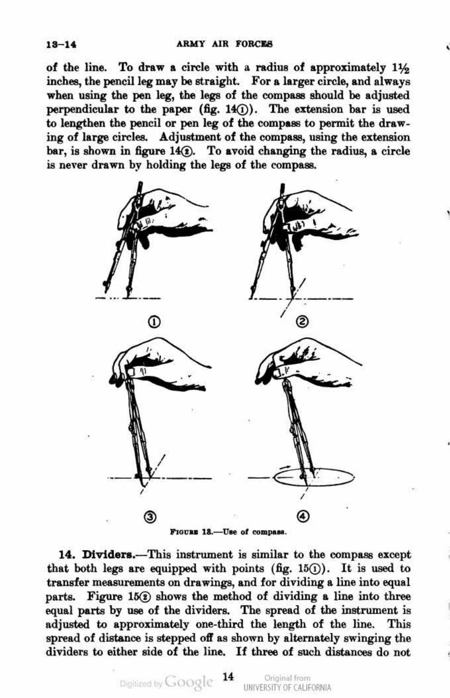
b. The compl\8!l is used with one hand. It may be opened with the geC(lnd finger and thumb (fig. l3@) and set to the desired radiua by placing the needle point at the center mark, adjust ing the spf'ead with the 8ilCOnd and third fingers (fig. 13@). After the radiua is set., the thumb and first finger 1I1'i,l raised w the handle (fig. 13(!). The compass is started at the neILr side of tbe cirele to be drawn and f'evolved -~lookwise as shown in figuffl 13(!), inclined slightly in the direction
( 12 Or'gir I<
UNM~\fTY Of (AllfORNIA
I
=.,.~-mOo, , "COO
--
7 7 ... , ., 0'"'.,_,",1 __ ., __ _
,.,"" .. 1(I._I(~l1 D. pea _ "" _t_ or _
--. PAY24NT + cli'ow QUILt.
.~ p-:::-~, : \ ' .... -
SPEEDBAI.L STUll
® I'tN
.,~~-, ,p--
HOl.Ct!!. , -. :
, , ' r : J
I!IALL
CD co,",p",!
® [XTtNSION BAli
0. • If UNIVERSITY OF OJ.lfORNIA
!
18-14, ARHY AIR J'OBCII8
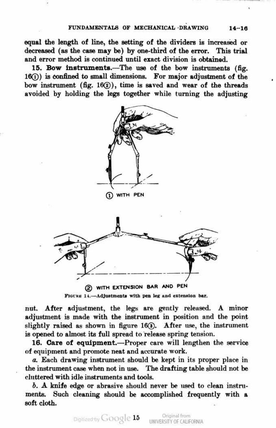
of the lin~, To dra,., a circle ,.,ith a radiUll of approximately 1:&h incbee, the peneilleg may be straight. For a larger circle, and Illways ,.,hen using the pen leg, the legs of the oompa811 Mould be adjusted perpendicular to the paper (fig, It(!), The ntension bar is used to lengthen the pencil or pen leg of the oompa!l! to permit the draw_ ing of large eircles. Adjustment of the oompaae, using the utension bar, is shown in figure l~ To avoid changing the radiue, a circle is ne\'er drawn by holding the legs of the romp'''
- '"
®
®
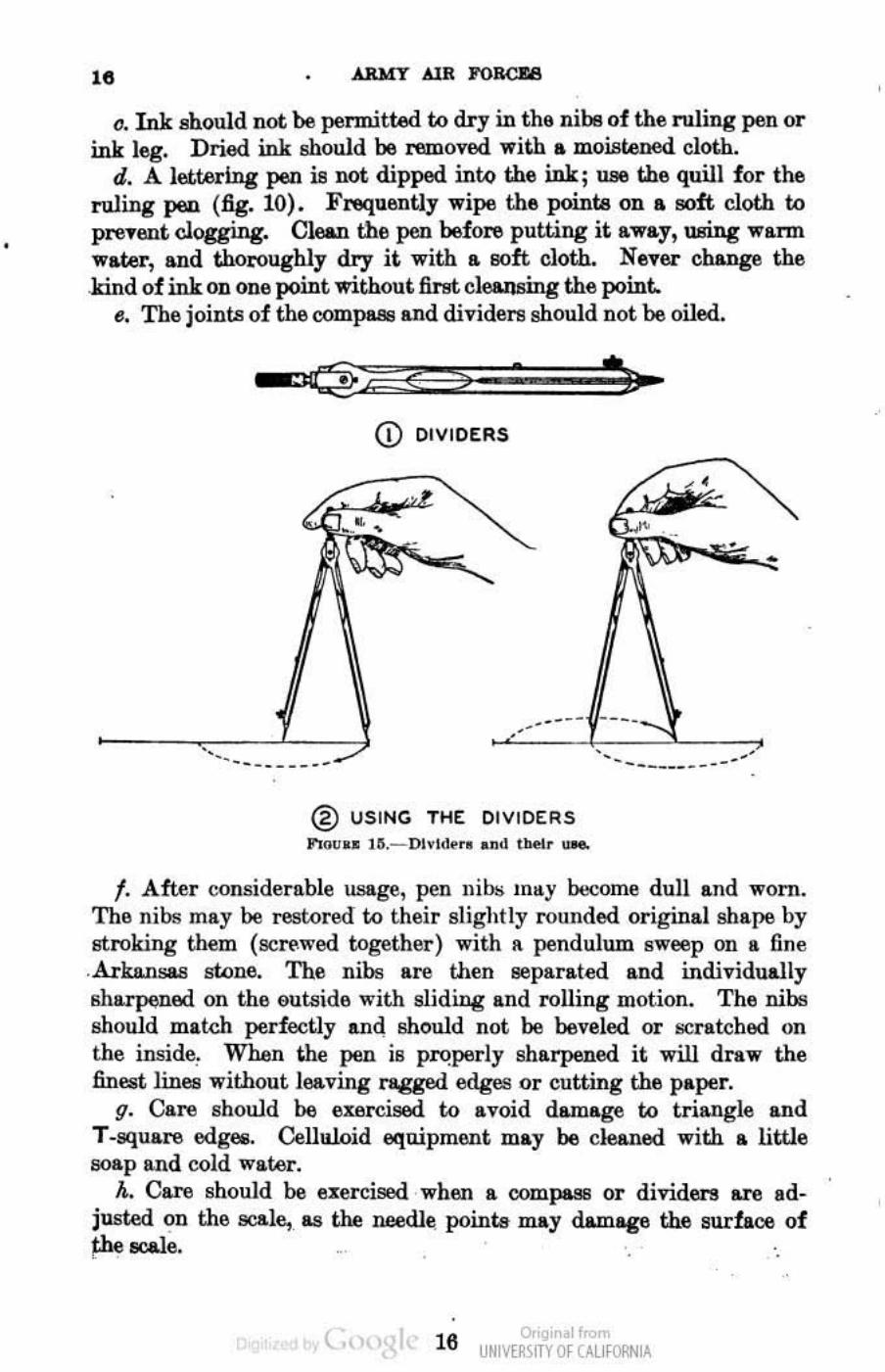
14. Divtden.- This instrument is similar to the oompa911 tU:cept that both legs are equipped with points (fig. 1~) . It is used to tI'1Lntder measurements on drawings, and for dividing a line into equal parts. Figure 16(!) MOWS the method of dividing a line into three equal parts by use of the dividers. The spread of the instrument is adjusted to approximately one-third the length of the line. This spread of distance is stepped 011 &8 shown by alternately swinging the dividel'll to either side of the line, If three of such diatanoes do not
( 14 o,'gir I< UNM~\fTY Of (AllfORNIA
,
,
•
FtTNDAMESTALS OF MECHANICAL ·DRAWING 14-1e
equal the length of line, the Betting of the dividers i8 incre.Bed or decreased (as the C&88 may be) by one-thUd of the error. This trial and error method is continued until enct division is obtained.
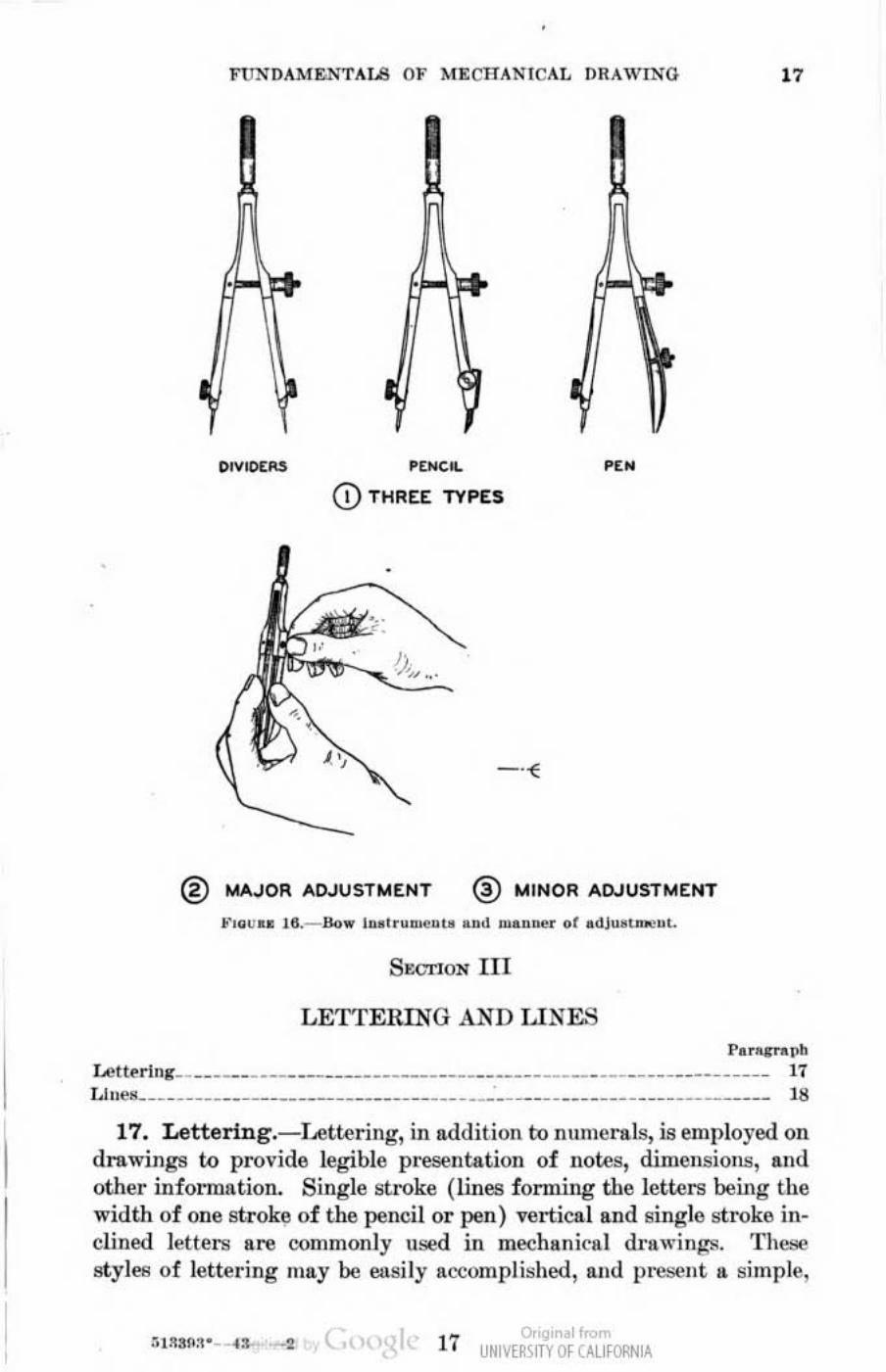
1~. Bow lnatru.ments.~The U88 of the bow instruments (fig. 160) is oonfined to small dimensions. For major adjustment of the bow instrument (fig. 16(!», time is saved and wear of the threads avoided by holding the lega together while turning the adjusting
<D WITH P(N
® WITH [JI.TEl'I5ION BAR AND
,., .. ~ •• 1I .~A4juo_to wIll> pea lou ud ut_lon .....
nut After .djulltment, the legs are gently relell.sed. A minor adjustment is made with the instrument in position find the poin" slightly raieed as shown in figure 16(!). After UIIe, the instrumellt is opened to almoet its full spread to 'release spring tension.
16. Can! of equipment.- Proper care will lellgthen the service of equipment and promote neat IIond IL"eurate l\·ork.
a. Each drawing instrument should be kept in its proper place in the instrument case when not in use. The drafting table should not be cluttered with idle instruments and tools.
b. A knife edge Or II.brasive should Del'er be used to dean instru· mente. Such cleaning should be acoomplished frequently with a 80ft cloth,
( o,'gir I< UNM~\fTY Of (AllfORNIA
•
•
,. c. Ink should not be permitted to dry in the nibs of the ruling pen or
ink leg. Dried ink should be l'6Oloved with a moistened cloth. d. A lettering pen is not dipped into the ink; U96 the quill for the
ruling pen (fig. 10). FrequenUy wipe the pointB on .. 110ft cloth to pre't'wt clogging. Clean the pen before putting it away, wring warm w&ter, and thoroughly dry it with a 80ft cloth. Never change the .kind of ink on one point without first cleansing the point.
B. The joint.'! of the compaB13 and divideI'fl should not be oiled.
-' ..
CD DIVIDERS
' . . __ .. -® USING THE DIVIDERS
...... u .. 1~.-DlvIMr •• nd IbeI, ""'
f. After considerable usage, pen nib.; may become dull and worn. The nibs may be restored to their slightly rounded original shape by stroking them (screwed together) with It pendulum sweep on a fine .Arkansas sWne. The nibs are then lleparated II.nd individually sharpened on the 6utllide with sliding and rolling motion. The nibs should mal.<:h perfectly and should not be beveled or scratched on the inside, When t.he pen is pl'(!perly sharpened it will draw the Ilnei>t Jines without leaving ragged edges or cutting the paper.
g. Care should be exercised to avoid damage to triangle and T-square edges. CellJlloid eqo.ipment may be cleaned with a little soap lind cold water.
A. Care should be l!Iercised when a OOWpasB or dividers are adjusted ~n the scale, 118 the needJ~ points ~y demage the surface of !:he scale.
t., 16 o,'gir . 1",,", UNM~\fTY Of (AllfORNIA
I
ruXDAMENTAI.8 O}" MECHAN ICAL DRAWING "
OIVIOtIOS .~.
CD THREE TYPES
•
® MAJOR AD.JUSTr.4ENT ® MINOR ADJUSTMENT
~""U" 111._ 110 .. lu."u .... u .. ud "' . ..... " "r . diu't n","'.
SOOTlON III
LETTElUNG AND LIN&'3 PorO¥J"tl.I'~
l..ett~rjng __ __ ________________ ________ ____ __ _________ ____ _______ __ ___ ___ Ii 1.1""' _____ ___ __ ______________________ ___ ____ · ____ __ __________ ___ _____ _____ 111
17. Lettering.- f..ette ring, in addition to numerals, is employed 011 drawings to provide legible p resentation of notes, d imensions, and other infonnation. Single stroke (lines forming the letters being the width of one stroke of the pencil or pen) vertical lind single stroke inclined letters are oommonly used in meo:!hanictl l drawi ngs. Theae styles of lettering may be easi ly accomplished, and preS(!nt " simple,
~ " 17 UNIVERSITY Of CALI fORNIA
ARI4T AIR FOBa18
balanced appearance. Vl'rtical capitals are generally used in the title block, while vertical or inclined capitals, or capital9 and lower-case letters, are used for notes_
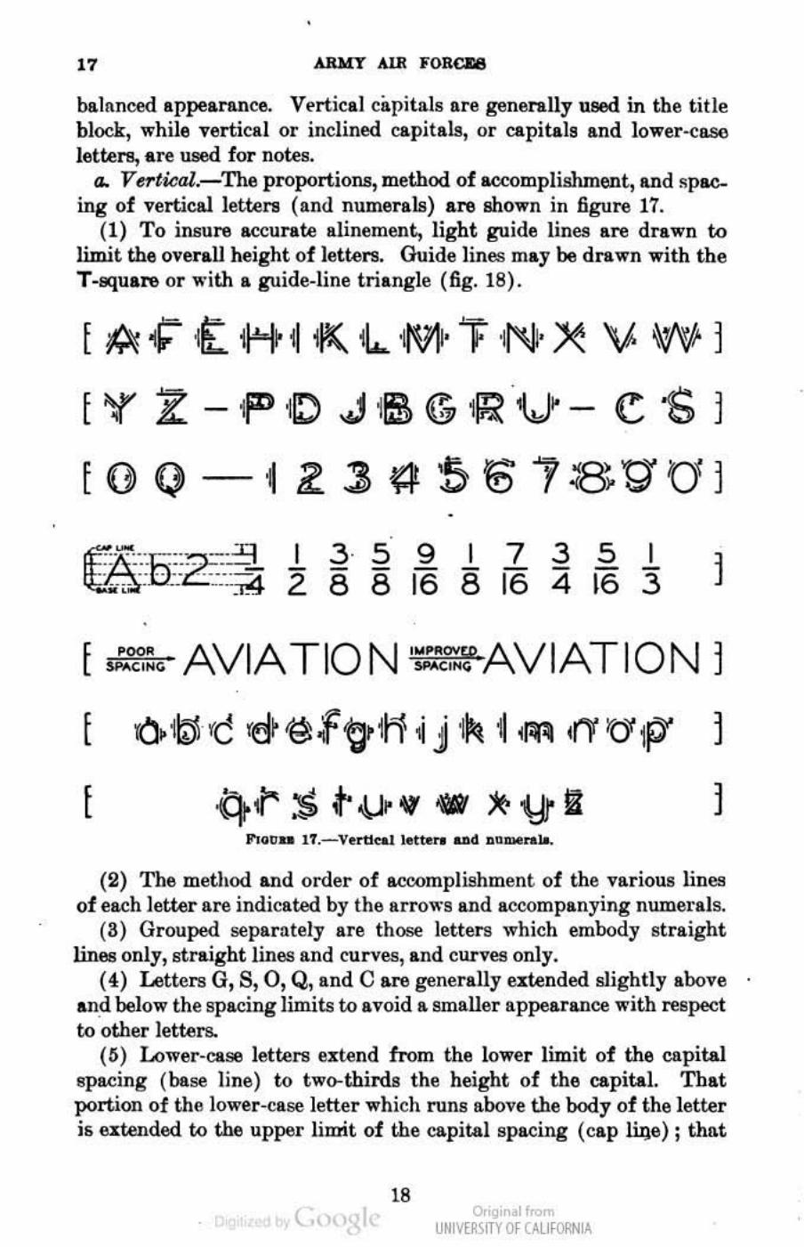
a. Vertical.-The proportions, method of accomplishment, and ~pacing of verticallettera (and numerals) are shown in figure 17.
(1) To insure accurate a1inement, light guide lines are drawn to limit the overall height of letters. Guidelines may be drawn with the T-square or " 'ith a guide-line triangle (fig. 18).
[~~,tIHi-H<,1I...M'TNX 'VI Wl
[ '( 11: - iF ,0 ",HS ~ 1~ 1(,) - c '6 1
[O¢) ~2~~~H518tHJl ,
I!CR"'5--= -'9 I 3 5 9 I 7 3 5 I tt...9.; - 'L-':~ 2 8 8 16 8 i6 4 i6 :3
[
AVIATION
10. '!oil rc 'd~ ~ f ~ 1[1 i j IPI ~ .~ ,11' 'D' IP'
q<l' :s ~ oW' If .. !(> 'Yr lit
1
1
(2) The method and order of acoomplishment of the various lines of each letter are indicated by the Itrrows and accompanying numerals.
(S) Grouped separntely are those letters which embody straight lines only, straight lines and curves, and curves only.
(4) Letters G, S, 0, Q, and C are generally extended slightly above an.d below the spacing limits to avoid a smaller appearance with respect to other letters.
(5) Lower-case letters extend from the lower limit of the capital spacing (base line) to two-thirds the height of the capital. That portion of the lower-case letter which runs above the body of the letter is extended to the upper lilIri.t of the capital spacing (cap li.g,e) ; that
l8 c. Or'gir I<
UNM~\fTY Of (AllfORNIA
FUNDAMENTAIB OJ' MECHANICAL DRAWING " which runs below the body is dropped below the base line one-third the capital spacing.
(6) Numenls of fractions IU"'6 two-thirds the size of fuli -size numerals, and e:z;tend above and below the limits of the full numerals for olle- third of the height of such numerals.
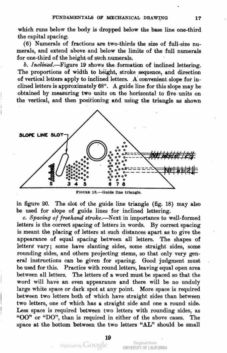
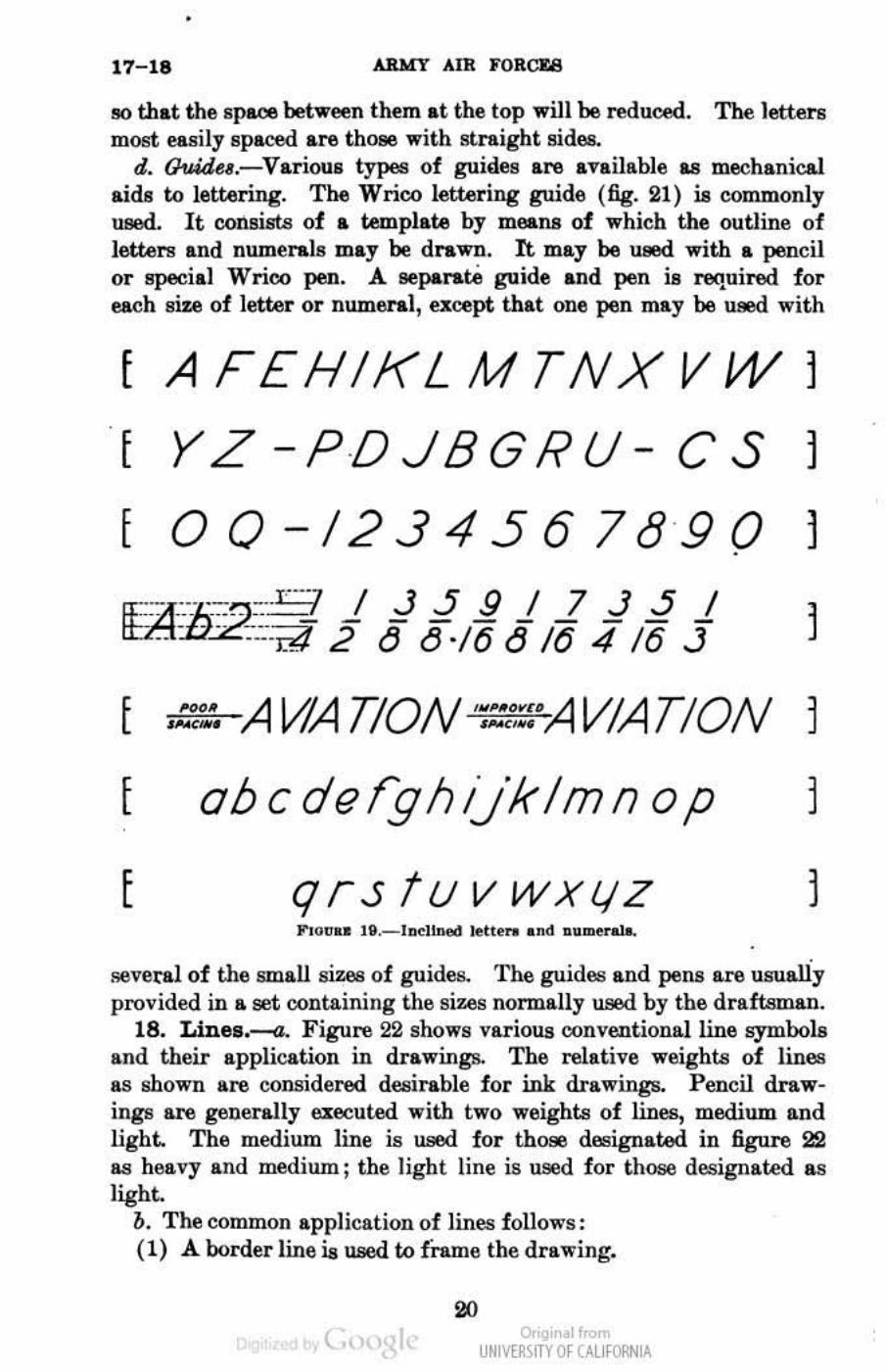
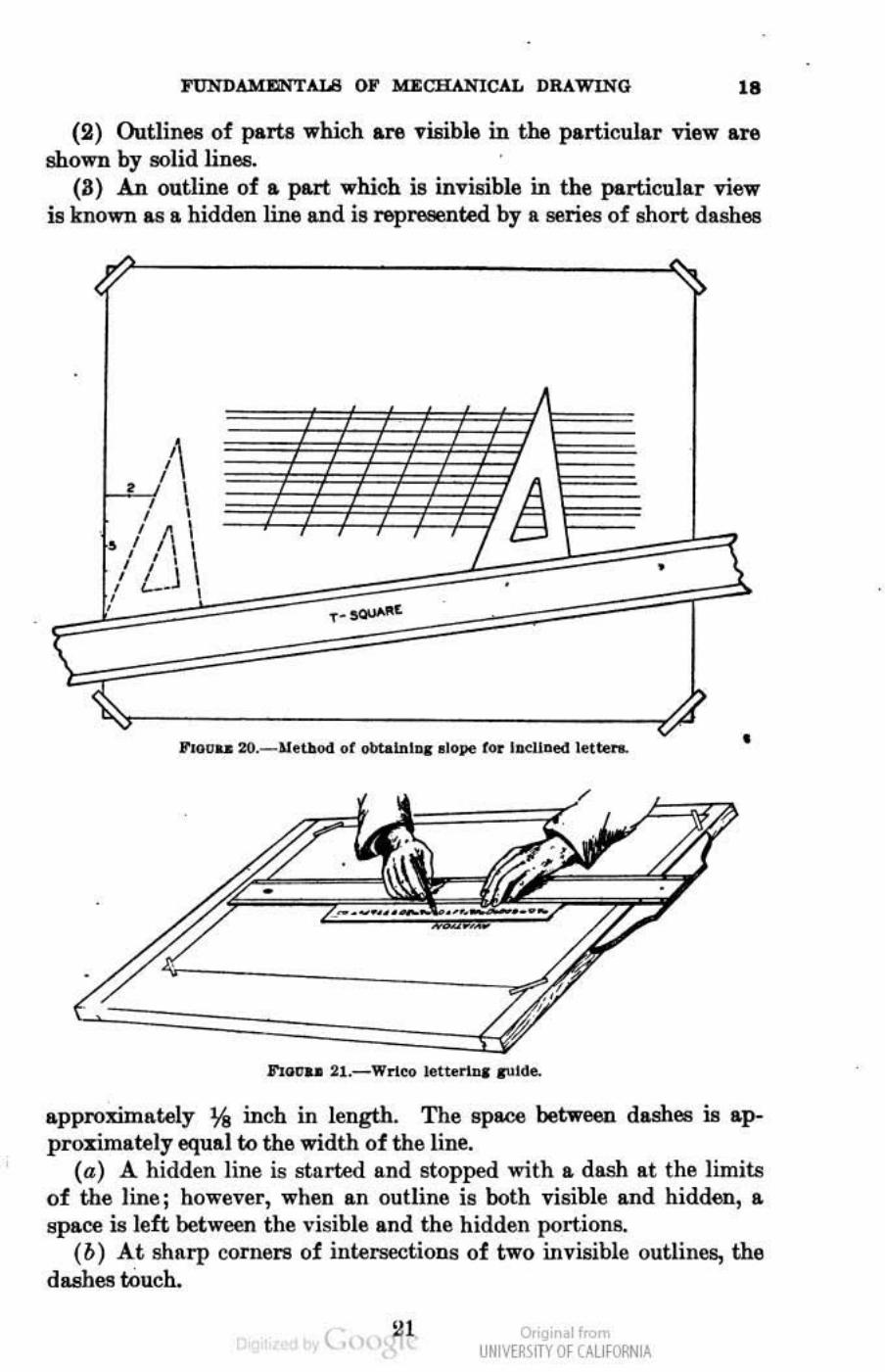
b. IMlined.-Figure 19 shows the .formation of inclined lettering. The proportioll8 of width to hftight, stroke sequence, and direction of verticallett.ers apply to inclin&d letters. A convenient slope for inclined letters is appro:z;imately 68°. A guide line for this slope may be obtained by measuring two units on the horizontal to five ·unitll on the vertical, IUld then positioning and using the triangle as shown
'Pi E ~ SUOT-,,/
.. ---•• • •
in .figure 20. The slot of !.he guide line triangle (fig. 18) may also be ueed for slope of guide lines for inclined lettering.
c. Spacing of freehand Itroke.-NeJlt in importance to weil-fonned letters is the correct spacing of letters in words. By correct spacing is meant the placing of letters at such distances apart as to give the appearance of equal spacing between all letoors. The shapes of letters" vary; some have slanting sides, some straight sides, some rounding sides, and others projecting stems, 90 that only very general instructions can be given for spacing. Good judgment must be used for this. Practice with round letters, leaving equal open area between all letters. The letters of a word must be spaced 90 that the word will have an even appearance. and there will be no unduly large white space or dark spot at any point. More space is required between two letters both of which have straight sides than between two letters, one of which has a straight side and one a round side. lPss space is required between tv.·o letters with rounding sides, as "00" or "DO", than is required in either of the above cases. The space at the bottom between the two illtteI"ll "AU' should be small ..
( o,'gir I< UNM~\iTY Of CAlifORNiA
•
17-18 ARMY AIR FORCU
!II) that the space between them at the top will be reduced. The Jettet"ll
mO!lt easily spaced are those with straight aides. d. Ouid~,.-Various types of guides are available as tnechanical
aids to lettering. The Wrico lettering guide (fig. 21) is commonly used. It consists of .. template by mea.ns 01 which the outline of letteI'!! and numenl, may be drawn. It may be U88d. with .. pencil or !!p9Cial Wrioo pen. A IleparalAi guide and pen is required for each sir.e of letter or numeral, except that one pen may be used with
[AFEHIKLMTNXVW 1
[ Y Z -PDJBGRU- C S 1
[ 0 0 - 123 4 5 6 789 0 1
IUtb~2E~ j iii! j iii j 1
,A \dATION' VIATION 1
abcderghUklmnop 1
[ qrstuvwXIIZ 1 Flo" .. It._IDol~ lett ... and uu .... r-'
several of the small sizes of guides. The guides and pens are usually provided in a set containing the sizes normally used. by the draftsman.
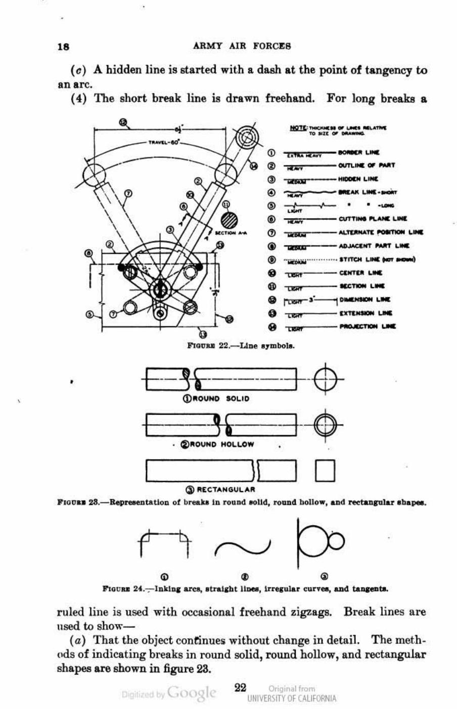
18. LineB.-a. Figure 22 shows various oonve.ntionalline symbols and their application in drawings. The relative weights of lines as shown are considered desirable for ink drawings. Pencil drawings are generally executed with two weights of lines, medium and light. The medium line ill used for thoae designaW in figure 22 as heavy and medium; the light line is UlJed for those designated &II
light. b. The common application of lines follows: (1) A border line is used to frame the drllwing.
t" o,'gir I<
UNM~\fTY Of (AllfORNIA
" (2) Outlines of parts which are visible in the particular view are
shown by solid lines. (8) An outline of a part which is invisible in the particular view
is known 18 So hidden line and is represented by a series of short dashes
1'I0u .. 2t._Wrteo letW1". .",1<Ie.
approximately lAI inch in length. The space between dashes is approximately equal to the width of thllline.
(a) A hidden line is started and stopped with a dash at the limits of the line; however, when an outline is both visible and hidden, a space is left between the "isible and the hidden portions.
(b) At sha.rp corners of inU!rseetions of two invisible outlines, the dashes tOuch.
( "' , o,'gir I< UNM~\fTY Of (AllfORNIA
18 ARMY AIR FORCES
(c) A hidden line is started with a dash at the point of t.ngency to an arc.
(4) 111e short break line is drawn freehand. F or Jong breaks a
•
/II:lI'_ .......... -_'woo ........ eo' I
G> 1 ....... Wi 2 12- .....
11> ....... """' .. '" _T () Q P - ....
@) . ;;;;;;: -- ..... ....... (11 ,;t;; I • • ' ...
(I) ....... ~ ......... ~ ..
~
~
W A
W 21 'I\":::Z'" _ ....
<e ___ -"'-. -- .... uLi"C>! ..............
e o • o e
lil
CC I
I lbO l .-
<bOl
LUI!
-_ ....... ....... --'" I .....
J"io" .. 22._L1z:e O1mbol •.
f -- -W------- I $-<D.OI.itoO IoOllD
I % -+$-iIl_DUMD I"X,LOW
I L-----;;-:;:=::!.ID 0 (JI.'CT .... GLJl ....
P,o .... 2lI.-P !V 2UOU,UoO of b.o.l:& 10 .ound .. U4, "'''04 boUo .. , &Ad ndaaplar obopilO.
ruled line is used with occasional freehand zigzags. Break lines are used to show-
(a) That the objoct continue~ without change in detail. The meth , (Ids of indicating breaks in round solidi round hollow, and rectangular shapes are shown in figure 23.
( 22 Or'gir t.-UNM~\fTY Of (AllfORNIA
FUNDAMENTALB OJ' MJ:CHANICAL DRAWING
(b) That only I portiolL of the entire object is represented. (e) That a section has been revolved in place.
10
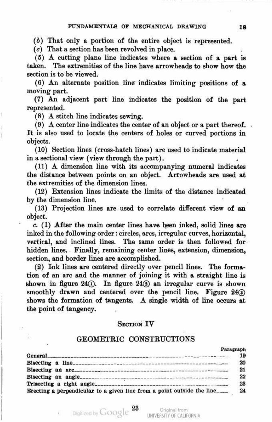
(ti) A cutting plane line indicates where a section of a part is taken. The extremities of the line have arrowheads to show how the section is to be viewed.
(6) An alremate position line- indicates limiting positions of a moving part..
(7) An II.djll.cent part line indiCII.tes the position of the part represented.
(8) A stitch line indicates sewing. (9) A center line indicates the center of In object or a part theroof.
It is also used to locate the centers of holll6 or curved portions in objeclll.
(10) Section lines (cross-hatch lines) lue used to indicate material in a sectional view (view through the part). .
(11) A dimension line with its accompanying numeral indicll.~ the distance between points on an object. Arrowheads are UIIed at the extremities of the dimension lines.
(12) Emnsion lines indicate the limits of the distance indicated by tbe dimenmon line.
(13) Projection lines are used to correlate different view of Ill.
object. c. (1) .After tbe main center linee have qe,en inked, solid Iinllil are
inked in the following order: circles, arcs, irregular curves, horizontal, vertical, and inclined linelil. The same order is then follo""ed for . hidden lines. Finally, remaining center lines, IIJ[tension, dimension, section, and border lines a1:& accomplished.
(2) Ink lines are centered directly over pencil lines. The formation of an are and the manner of joining it with a straight line is lIhown in figure 24Q). In figure 24@ In irregular curve is shown smoothly drawn and centered over the pencil line. Figure 2-4@ shows the formation of tangents. A Bingle width of line occurs at the point of tangency_
SECTION IV
GEOMETRIC CONSTRUCTIONS P ........ 1>h Oeneral _ __ _______________ ____ ___ _____ ._______________ ___________ _ 19
Blwctlnc II. Hoe________ __ _____ __ ______ ______________________________ 20 BlMct10C all u c ____ ____ ____ ____ ___ ______________ ________ _ .__________ 21 Bllectln&" II.D lI.o&"le _______________ ~- _______ _____ . __ __ _ _________ _ _____ 22 Trllect1nc • rJaht all&"le_ ___ _____ ____ _____ ________ ____ ___ ________ ____ 28 Erectlua a perpeodlcuial" to a Cheo 1I0e f rom a polot ouWde the I1ne___ 24
( 28 o,'gir I< UNM~\fTY Of (AllfORNIA
, ..... h .......
ETeethll I. perpendicular to '. ciTeD ]lIN! trom I. point In the 11m!________ lIlS DtrldlDI' I. IIDe Into equal PIlrta~______________ ____ __ _ _ ___ ____________ 26 Drawlna a drcle tbrouah thn!e points not In I. IItral$ht 11De.. .. __________ 27 Ooo.tructJng I. IIQllue __________ ____________ ~___________________ 28· Constructing I. reKtdar peotacOIl____________________ _________ _________ 2»
ConatrueUlI, I. ~ bez.gOlI_________________ __ __ ______ ___ _________ 80 eonatrnctinc a regular octagOlI _____ __ _______ __ ____ ___ ... ___ ___ ____ ____ Sf
Drawing 1.0 an: tall~lIt to two IInl!ll-_____ __ __________ _______ _________ S2 Dno.wlog an arc In I. "-bt &1\11"_________ ___ ______ _____ ____________ 83 Drflwlng an ell!P"!_________________________________________________ IW
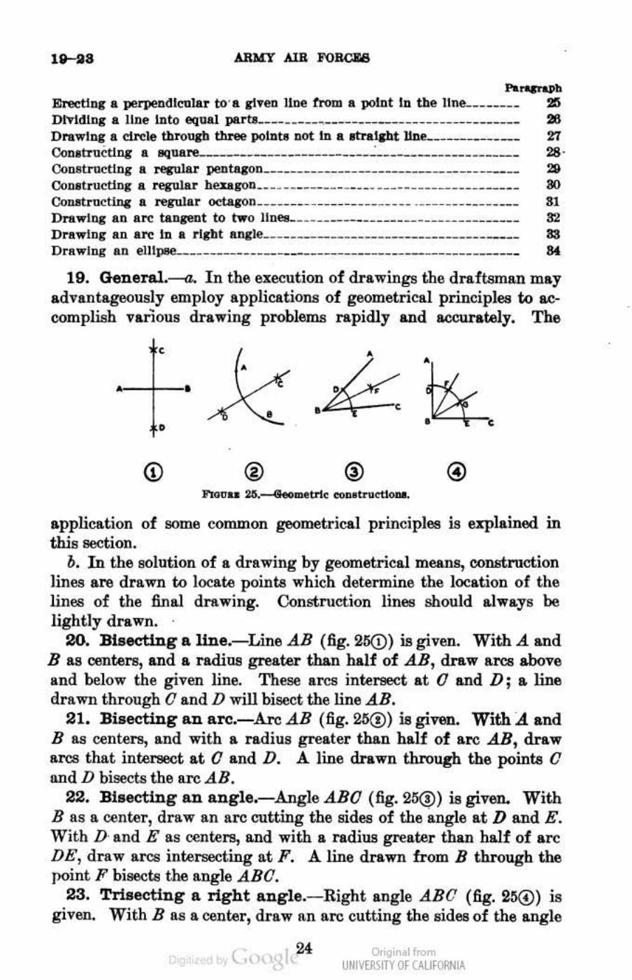
19. General.---a. In the execution of drawings the draftsman may advantageously employ applications of geometrical principles to accomplish various drawing problems rapidly and accurately. The
, •
• •
®
application of !lOme common geometrical principles is explained in this section.
b. In the solution of a drawing by geometrical means, construction Jines are drawn to locate poinu which detennine the location of the lines of the final drawing. Construction linE!!! should alwa.ys be lightly drawn . .
20. Bisecting II. Une.- Line AB (fig.21KI) is given. With A and B a8 centers, and a radiua greater than half of .All, draw R.I'CIl above lind below the given line. These lircs intersect at 0 and D; a line drawn through 0 and D will bisect the line AB.
21. Bisecting an arc.-ArcAB (fig. 25{!) is given. With A and B as centers, and with a radius greater than half of are .AB, draw arcs that intel'8OOt at a and D. A line drawn throup the poinu 0 and D bisects the arc .AB.
22. Bisecting an angle.-.Angle .ABO (fig. 25@) is given. With B IlS a center, draw an arc cutting the sides of the angle at D and E. With D and E as centers, and with a radill! greater than half of arc DE, draw arcs intersecting at F. A line drawn from B through the point F bisecta the angle .ABO.
23. Trisecting a right angle.- Right angle ABO (fig. 2lS@) is given. With B lUI a center, draw an arc cutting the sides of the angle
( 24 Or'gir I< UNM~\fTY Of (AllfORNIA
FUNDAMENTALS OF ~lCAL DRAWING ..... , at D and E. With D and E as centers, and with the same radius, draw arcs intersecting are DE at F and G. Lines drawn frow B through pointe fl and G trisect the angle ABO.
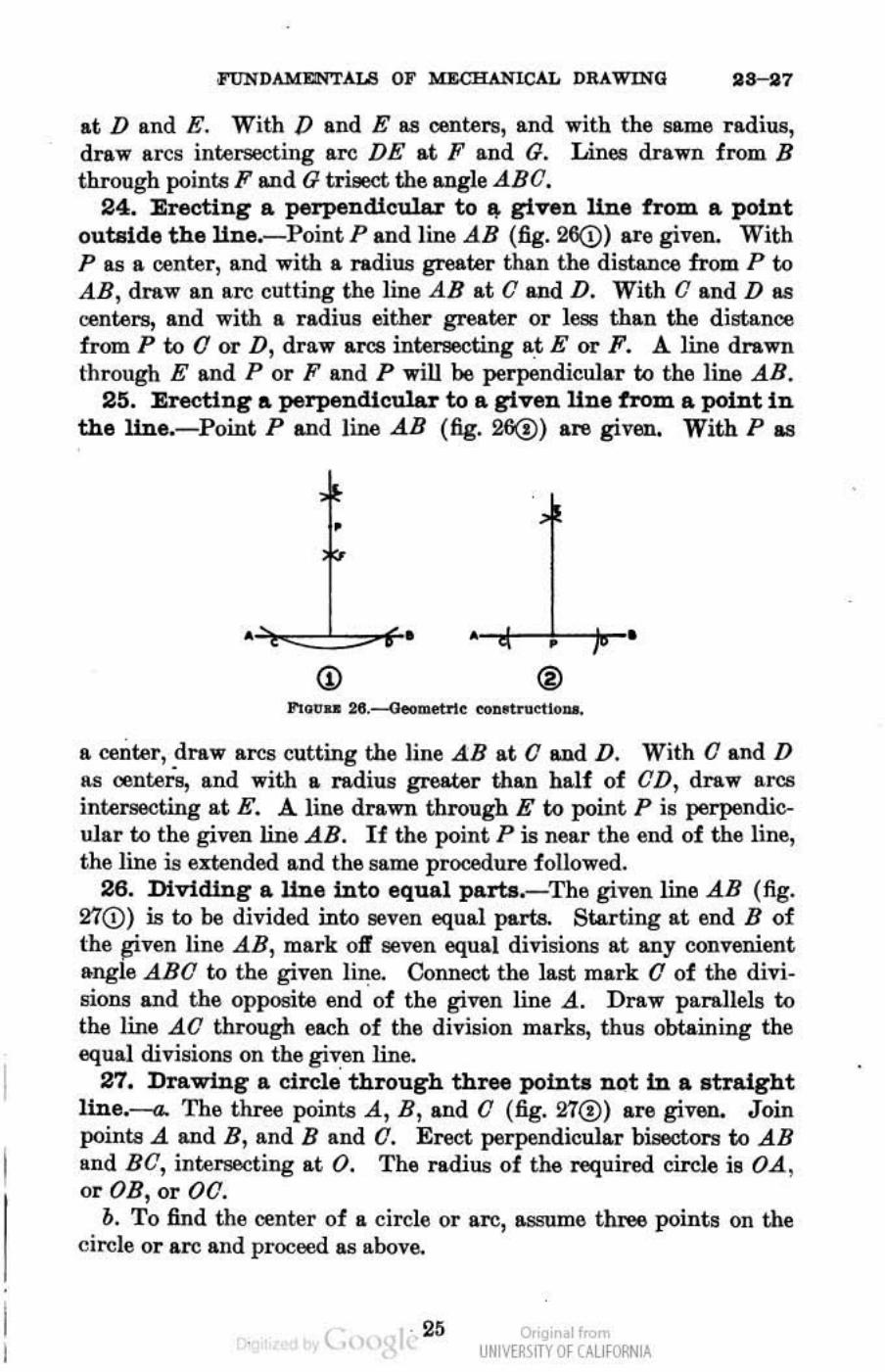
24. Erecting a perpendiculAr to q. given line from a point outside the line.-Point P and line AB (fig. 26(!) are given. With P as a center , and with a radius greater than the distance from P 00 AB, draw an arc cutting the line AB at 0 and D. With 0 and D as centers, and with a radius either greater or less than the distance from P 00 0 or D, draw arcs intersecting a,t E or F. A. line drawn through E and P or F and P will be perpendicular 00 the line AB.
25. Erecting a perpendtcnler to a given Une from a. point in the line.-Point P and line AB (fig. 26(!) are given. With P as
•
a center, draw arcs cutting the line AB at a and D. With a and D as centers, and with a radius greater than half of aD, draw arcs intersecting at E. A. line drawn through E to point P is perpendicular to the given line AB. If the point P is near the end of the line, the line is extended and the same procedure followed.
26. Dividing a line into equal parla.-The given line AB (fig. 270) is to be divided inw !!even equal parts. Starting at end B of the wven line AB, mark off seven equal divisions at any convenient angle ABO to the given line. Connect the last mark a of the divi· sions and the opposite end of the given line A. Draw parallels to the line AO through each of the division marks, thus obtaining the equal divisions on the given line.
27. Drawing a circle' through three points D(lt in a straight line.-a. The three pointe A, B, and 0 (fig.27@) are given. Join pointe A and B, and Band O. Erect perpendicular bisectors to AB and BO, intel'86Cting at O. The radius of the required cirohl is OA , or OB, or 00.
b. To find the center of a circle or arc, assume three points on the circle or arc and proceed as above.
( . 25 o,'gir .1",,", UNM~\fTY Of (AllfORNIA
as-so ARMY AIR FORCES
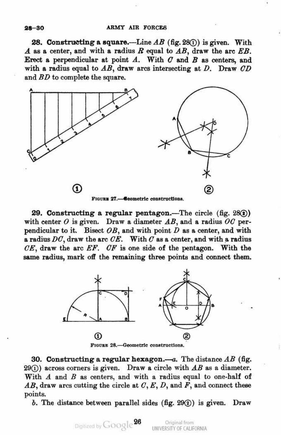
28. Con.truettng a square.- Line AB (fig. 28Q) is given. With A lUI a center, and with a radius R equal to AB, draw the arc EB. Erect a perpendicular at point A. With a and B as centers, and with a radius equal to AB, draw arcs intersecting at D. Draw aD and BD to complete the square.
®
29. Constructing a regular pentagon.-The circle (fig. 28(!) with center 0 is given. Draw II, diameter AB, and a radius 00 perpendicular to it. Bisect OB, and with point D as a center, and with a radius DO, draw the arc OE. With 0 as a center, and with a radius OE, draw the arc EF. OF is one side of the pentagon. With the same radius, mark off the remaining three points and connect them.
•
• •
<D lID Floon 28.--<J.eometm co ... t .... Uon •.
30. Constructing a regular hexagon.-a. The distance AB (fig. 29(!) across corners is given. Draw a circle with AB as It diameter. With A and B Il8 centers, and with a radius equal to one-half of AB, draw arcs cutting the circle at 0, E, D, and F , and connect theee points.
o. The dist..nce between parallel sides (fig. 29(1» is given. Draw
( 26 ar'gir I< UNM~\fTY Of (AllfORNIA
FUNDAMENTALS OF MECHANICAL DRAWING 80-38
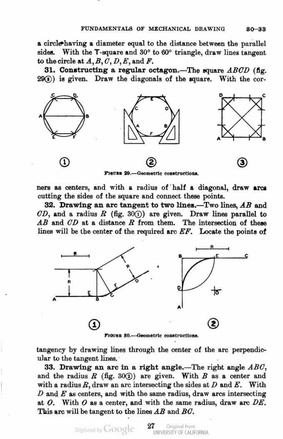
.. circle-baving .. diameter equal to the distance between tbfl parnlllli aides. With the T-squ.re .nd so· to 60° triangle, draw linu tangent to the circle at A, B, 0, D, E, and F.
31. Conatructl.ng a regular oetagon_-The equare ABOD (flg_ 29@) is given. Draw the diagonals of the lIquu-e_ With the oor-
CD ®
00l"8 as oonteI1l, and with • radius of ' balf a diagonal, draw arca cutting the sides of the square and connect these points.
32. Drawing an are tangent to two llDea.-Two lines, AB and OD, and a ndius R (fig. 30@) are given. Draw lines parallel to .!B and OD at a distance R from them. The intel'geCtion of tbe.e lines will be tbe center of the required are EF. Locate the poinh 01
, ----=;;:::"f=:....-'r •
. .-----'-•
tangency by drawing lines through the center of the are perpendioulRr to the tangent lines.
33. Drawing an a.rc in a right angle.-Tbe right angle ABO, and the radius R (fig. SO(!) are given. With B as a oenter and with a ndiusR,draw an are inte~ting the sides atD and E. With D and E as centers, and with the AIDe radius, draw ares intersecting at O. With 0 as a center, and with the same radius, draw arc DE. 'l'bls are will be tangent to the lines.AB and BO.
( Zl Or'gir I< UNM~\fTY Of (AllfORNIA
84-86 ARlolT AlR FORCES
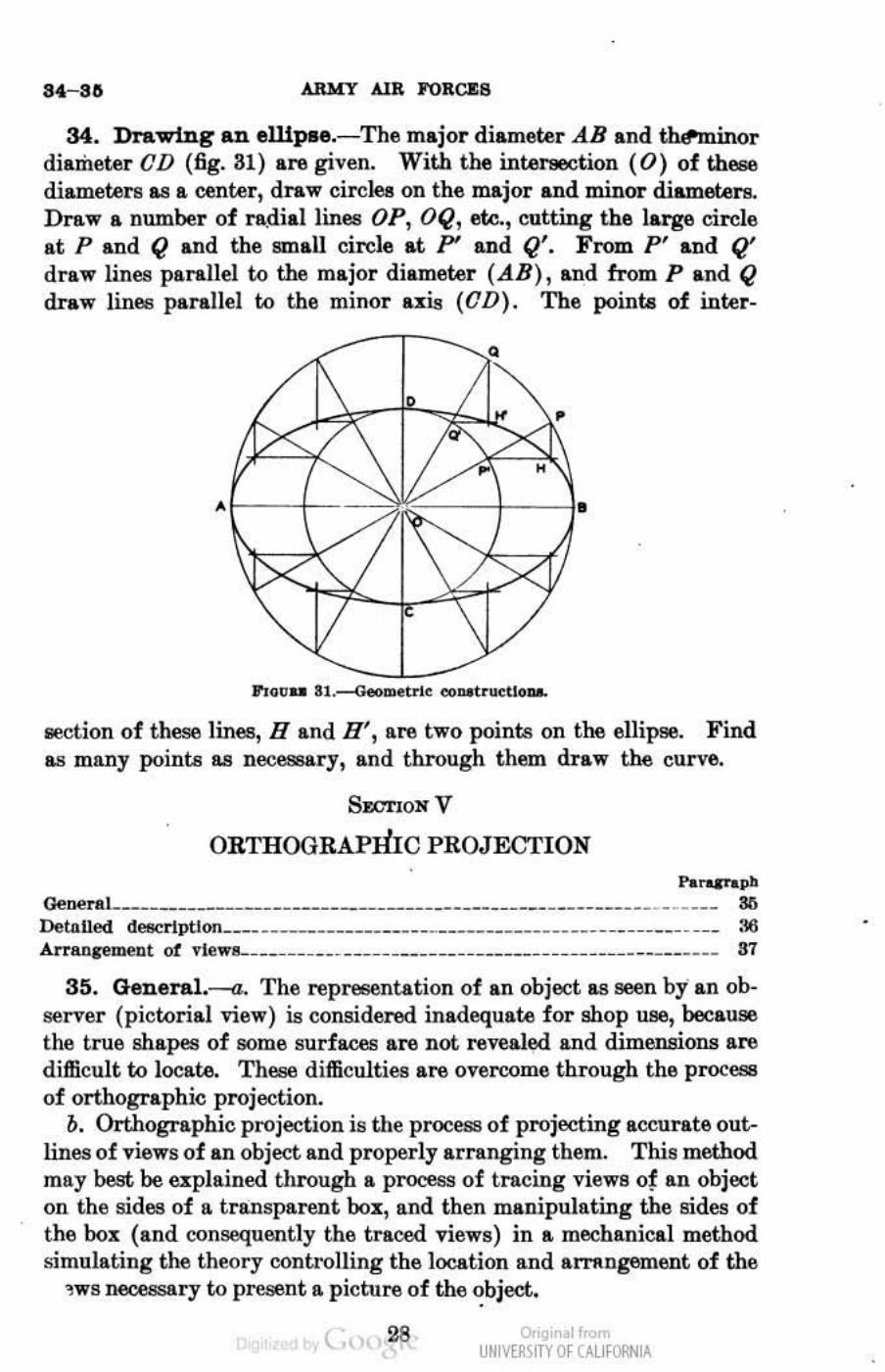
34. Drawing an e1.l.ipae.- The major diame~r AB and tMominor diameter CD (fig. 31) are given. With the int.eraection (0) of these diame~rs a.s a cenlAll', draw circles on the major &.Ild minor' diameters. Dl'aw a numbel' of ra.diallines OP, OQ, etc., cutting the lal"g9 cirele at P and Q and the small circle at P' &.Ild Q'. From P' and Q' draw lines parallel to the major diameter (AB) , and from P and Q draw lines parallel to the minol' U:UJ (CD). The point. of inlAll'-
•
--.
8OOtion of these lines, Hand H', are two points on the ellipae. Find a.s many points as necCC9l'Y, and through them draw the curve.
Sr.cTlON V
ORTHOGRAPIDC PROJECI'ION
h_" OeneraL_____________________________________________________________ ___ S6 Detaned de8Crlptlon____ _____________ ____________________ ___ __________ ___ :t6 An'lln,eroeut of ~le1n-__ __ ____ _______ ____ ____ __________ ______ _________ __ 91
35. General.----a. The representation of an object as IIOOn by an observer (pictorial view) is considered inadequate for shop illIEl, because the true shapes of some surfaces are not revealed and dimensiona are difficult to locate. These difficulties are overcome through the process of orthographic projection.
b. Orthographic projection is the process of projecting accurate out.lines of views of an object and properly afnnging them. This method may best be explained through a process of tracing views of an object on the sides of a transparent box, and then manipulating the sides of the box (and consequently the traced views) in a mechanical method simulating the theory controlling the location and arT1l.ngement of the
1 W S V6cessery to present a picture of the ~bject.
( o,'gir I< UNM~\fTY Of (AllfORNIA
•
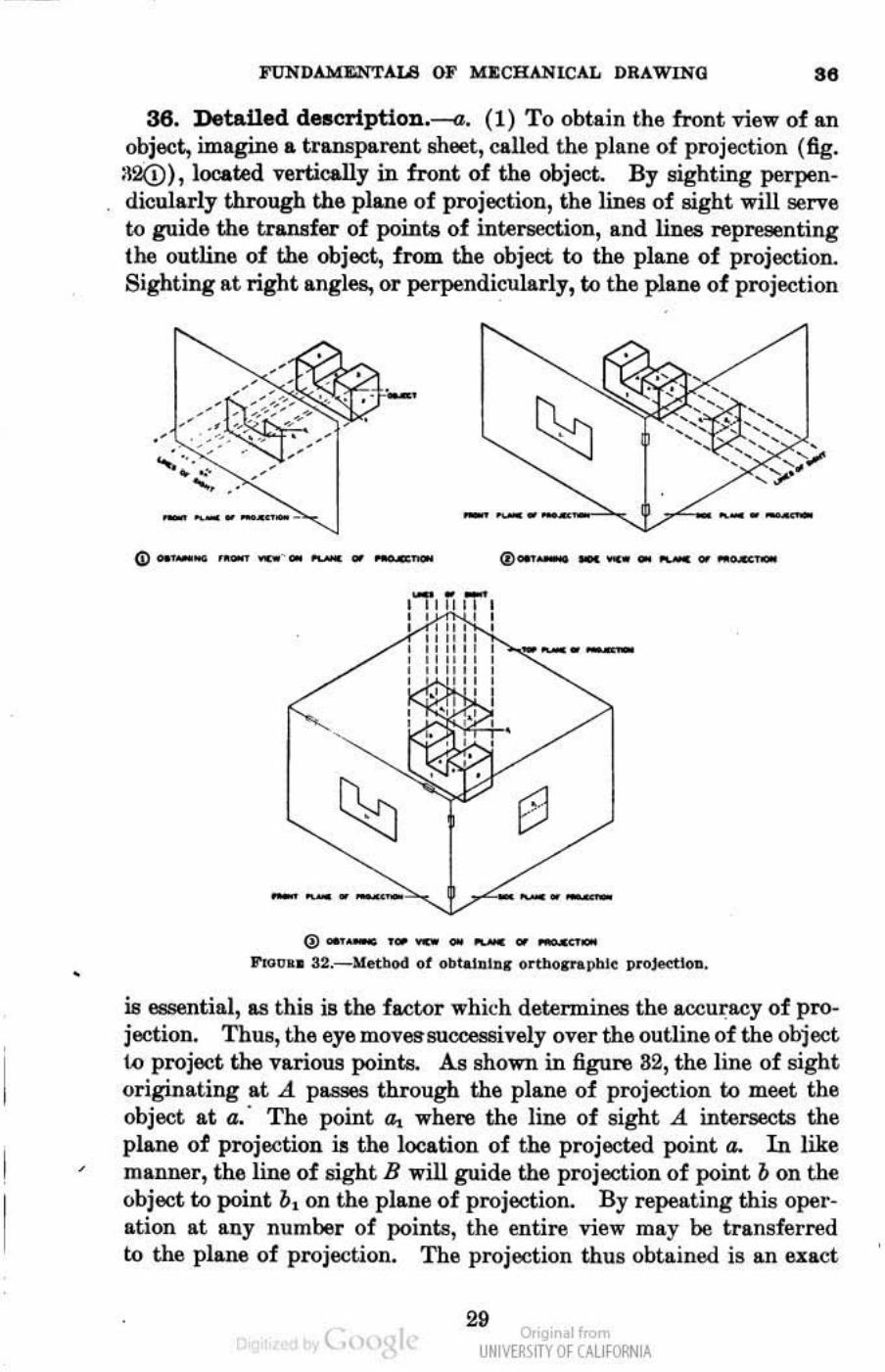
FUNDAMENTALS OF MJ:CHANICAL DRAWINO .. 36. Detailed deBCription.--a. (1) To obtain the front view of an
object, imagine a tnnsparent sheet, caned the plane of projection (fig. :l2(!), located vertically in front of the object. By flighting perpendicularly through the plane of projection, the lines of sight will serve to guide the tr&lUlfer of pointa of intersection, a.nd lines representing the outline of the object, from the object to the plane of projection. Sighting at right angles, or perpendicularly, to the plane of projection
--_ .. -'::", (j) -- ,-. - " .. -- - --
(1) ___ ........... __ _
-
..... ,,- ... (iJ __ ... _ .. ...- .. 0" "", ••
!rt<:>OIl 32._Metbod ot ....... I"II'r or.borrap.ble proJedloa •
is essential, as this is the fM:oor which determinet:l the accuracy of pro. jection. ThUB, the eye move!JSuccessively over the outline of the object 1.0 project the various points. As shown in figure 82, the line of sight originating at A pusas through the plane of projection to meet the object at a. ' The point a. where the line of sight A intersects the plane of projection is the location of the projected point a. In like manner, the line of Bight B will guide the projection of point b on the object to point O. on the plane of projection. By repeating this operation at ILny number of points, the entire view may be transferred to the plane of projection. The projection thus obtained is ILn e.xaet
( Or.gir I< UNM~\fTY Of (AllfORNIA
.. outline of the front view of the object, and may be clearly and accurately dimensioned.
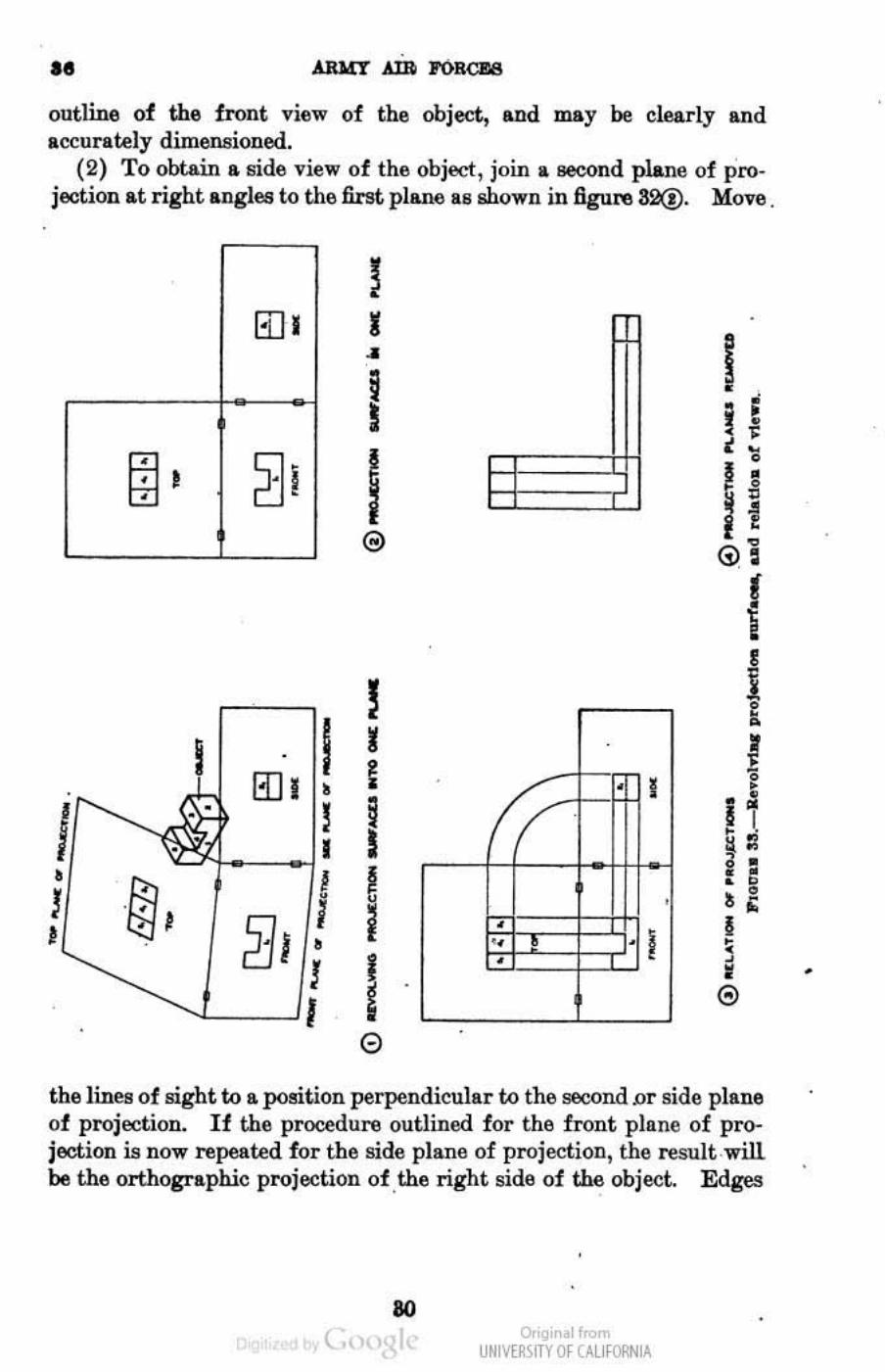
(2) To obtain .. side view of the object, join II. second plane of projection at right angles to the first pllLJW) Ils w.own in figu~ S2(!). Move
13]1
fBI 2Ji
I 13]1 •
I ! 1
• &'
I )
l1l I I •
)
I
l I • I I e
I I I .
i I
/
I I
': I .
0
• I
,
. !
I H , , I •
J f Gi' f t
.) I I i; • • • 0 , ' • I , • • ®
the lines of sight to a position perpendicular to the second D r side plane of projection. If the procedure outlined for the front pla.ne of projection is now repeated for the side plane of projection, the result will be the orthographic projection of ,the right sida of the object. Ed~
ao ( o,'gir . 1",,",
UNM~\fTY Of (AllfORNIA
,
FUNDAME..""TALS OF MECHANICAL DRAWING 3 b-37
and Burfaces which are invisible in the plane of projection are indicated by the conventional symbol for hidden lines.
(3) To ohtain a top view of the object, join a third plane of projec_ tion horizontally above and at right angles to the front and Bids planes (fig. 32(!). Movs the lines of sight to a position perpendicular to ths third 01' top plans. Ths lines of sight will now be parallel to the front and side planes. Repeat the procedure h~tofore outlined to .lbtain the orthographic projection of the top of the object.
b. If the side and top planes are imagined to be hinged w the front plane and are revolved away from the object (fig. 33(i) until they coincide with the f ront plane, the three views appeal' on the same pla.n&of projection (fig. 38(!). Figure 8S(!) illustrates the relationship of the three views ; in figure 83@ the views are shown, as on a drawing, with the projection planes removed.
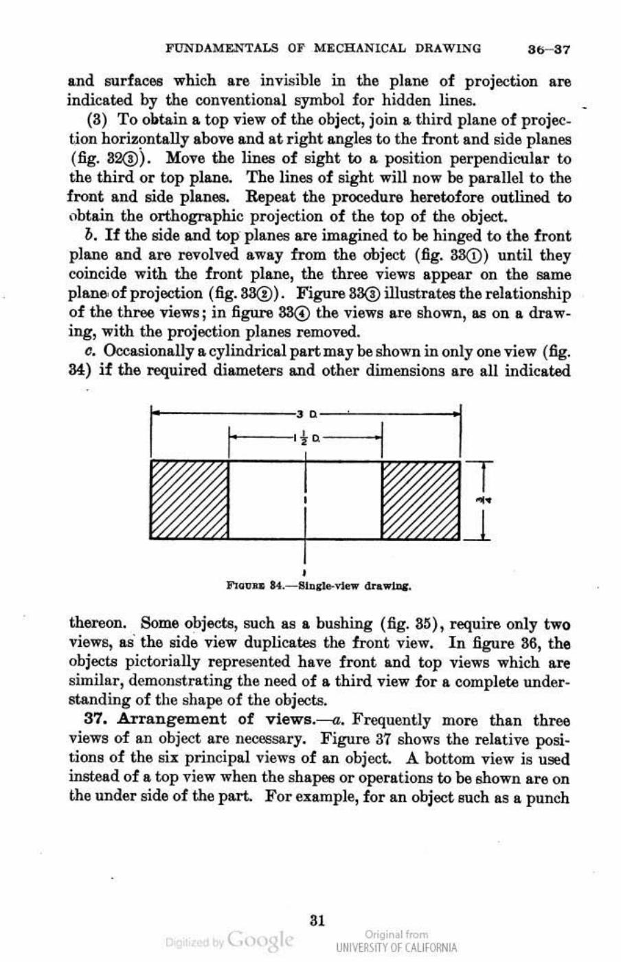
c. Occasionally a cyJindrical part may be shown in only one view (fig. 34) if the n>quired diameters and other dimensions are aU indicated
, ••
, F1GVU k.-,""Ile-ne .. <In.wU>&-.
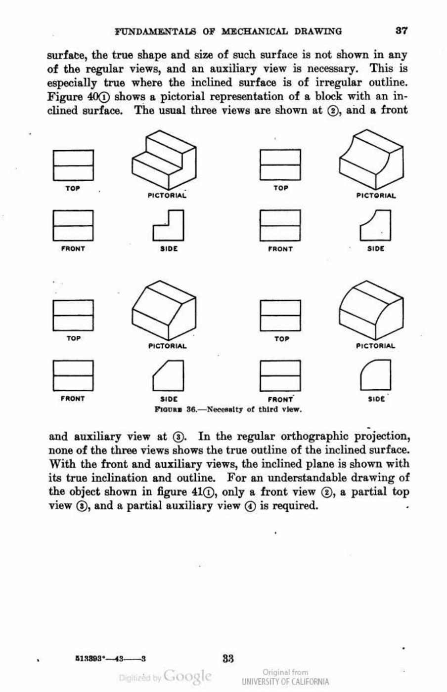
thereon. Some objects, such as a bushing (fig. 8!S), require only two views, as' the side view duplicates the front view. In figure 86, the objects pictorially represented have front and wp views which ano similar, demollstrating the need of a third view for a complete understanding of the shape of the objects.
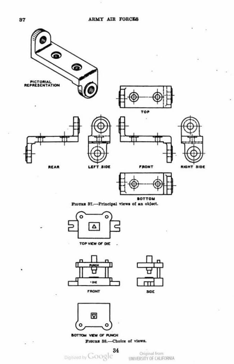
37. Arrangement of views.------a. Frequently more than tbree views of an object are necess9 ry. Figure 37 shows the relative posi. tions of the si l: principal views of an object. A botwm view is used instead of a w p view when the shapee 01' operations w be shown are on the under side of the part. For CJ.:ample, for an object such as a punch
'1 t., o,'gir . 1",,", UNM~\fTY Of (AllfORNIA
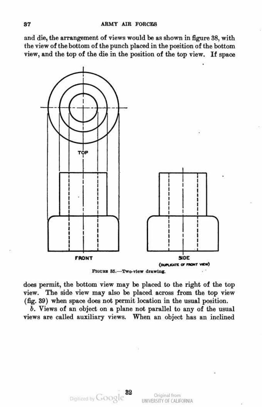
87 ARMY AlII. FORCES
lind die, the arrangement of views would be liS shown in figure 38, with thll view of the bottom of the punch placed in the position of tbe bottom view, and the top of the die in the position of the kip view. If space
,
/ rt-- '\ - f-- - - -
J+<[ ", .. ,
, , , , , , , , , , , , , , , , , , , , ,
Tl i ! , , , , , , , , , , , , , , , , , , , , , , , , , , , ,
, , , , , , , , , , , , , .
,.fIONT . " ( .............. _....,
......, .. SII .---T'!<o-1'1_ cI ..... !DC.
does permit, the bottom view may be placed to the right of the top view. The sid6 view may also be placed across from the top view (fig. 39) when spa06 does not permit location in the usual position.
b. Views of an object on a plane not parallel to any of the usual views are caned auxiliary views. When an object has an inclined
( .. o,'gir .1",,",
UNM~\fTY Of (AllfORNIA
•
FUNDAMLNTALS OF M.:ECRANlCAL DRAWING '1
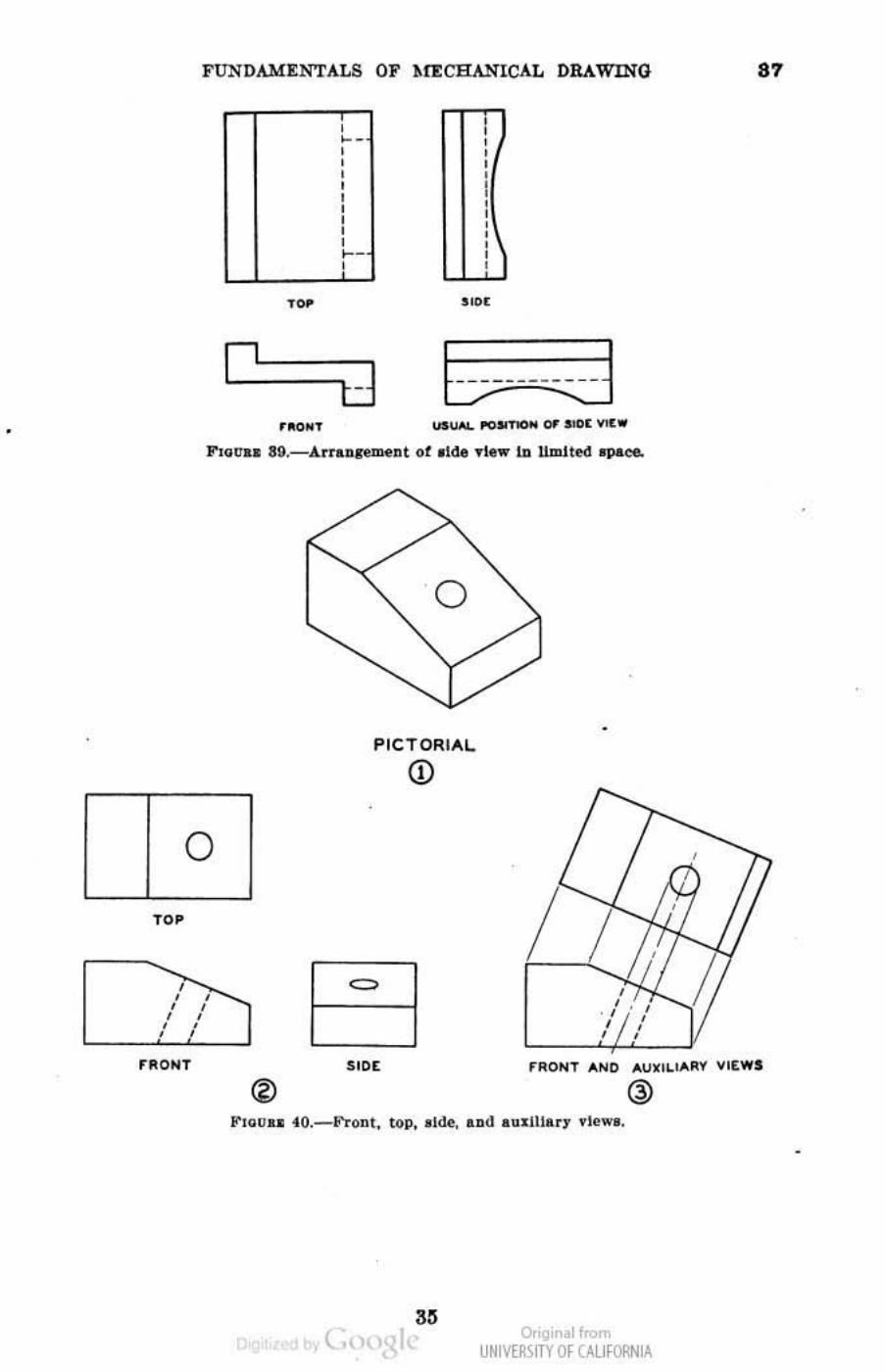
surfate, the true sbape and size of such surface is not shown in any of the regular vieWll, and an au:r.:iliary view is ne<:essary. This is especially true where the inclined surface is of irregular outline. Figure 4OQ) shows a pictotial representation of a block with an inclined surface. The usual three views are shown at @, and a front
El El 'M . '" .' CTO~ "'" " CTO~"""
El 2J El cJ '~ONT lODE 'RON T SIDE
El El roo ,,.
_TO~ ...... . ,CTOR""L
El LJ El 0 '~ONl SlDt .RONT SlOt
,., .. " •• SII.- N_U1 01 tbl rd Ylew.
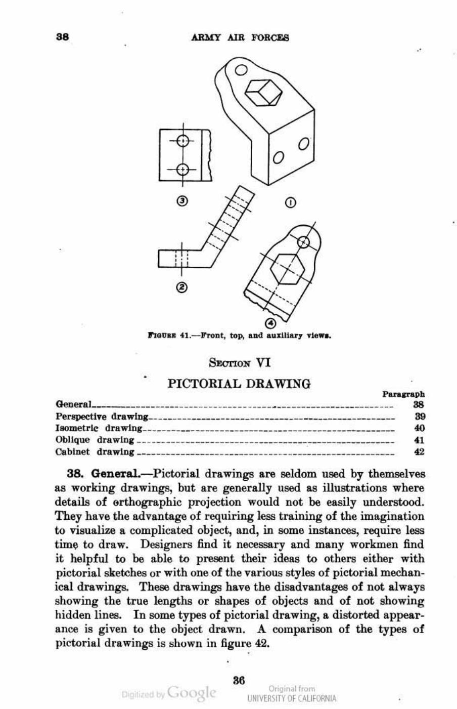
-and au:r.:iliary view at (i). In the regular orthographic projection, none of the three views shows the true outline of the inclined surface. With the front and auxiliary views, the inclined plane is shown with its true inclination and outline. For an understandable drawing of the obje<:t shown in figure 410, only a front view <!), a partial top view (!), and a partial auxiliary view @ is required.
( Qr'gir . 1",,", UNM~\fTY Of (AllfORNIA
•
'7
,
... ,TOAl"'" JI(.~RU(NTA1lON
•
AR~ AIB ro8cq
1.&'" "011:
10TTOII n o",,", 17.- Pr1acq>al 01 .... of .. oIIJ«t..
o 0
• . 1' ..... _OI'OUO!
34
-
, u~l~mITYOf (Allt~1A
n ... " "DC
•
FUNDAMENTALS OF hrE CHA."iICAL DRAWlNQ "
, I ,
I
o
, I
I
r lloNT
, ", , , , , , I , "-
LL_LJ'
, , , , i I , , , , ,
tJ b umd '''OWT
o
PICTORIAl.
Q)
=
" (
/ / ,
/ , ,
,
,~.j , , , r RONT AN I> .. " . ,LlAltI VI&WS
@
o,'gir . 1",,", UNM~\fTY Of (AllfORNIA
as
Gene .... ]
•
• • ...
ARMY AIR FORCroS
o o
SEOrION VI
PIcroRIAL DRAWING
. '
Panpaph ___ .____________ _____ _______ ___ __ ____________________ 88
Pe'lq)e(:til'e dn.wlnl___ _________________ _________ ___ __________________ 89 laometr\e dra willl _____ .___ _ _ __ __ _ _ _ _ __ __ _ __ _ _ _ _ ___ _ ___ _ _ _ __ __ _ __ ____ 4(1
Oblique draW!!'1 _ _____ ____ ______________ ____ ________________________ ,u Cabinet dr.wlne ._________________ ___ __________ ______________________ 42
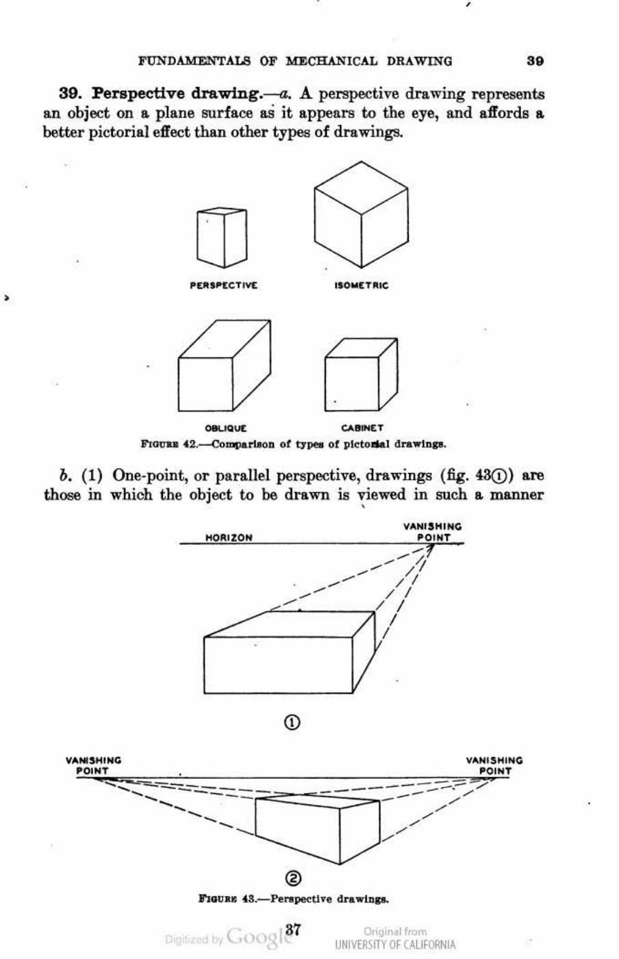
38. General.- Picwrial drawings are seldom used by theIIl8lllves as working drawings, but are generally used as illustrations where details of orthographic projection would not be easily understood. They have the advantage of requiring less training of the imagination to visult.liz..e a complicll.Wd obje<:t, and, in some instances, require less timf;! to draw. Designers find it necessary and many workmen find it helpfuJ to be able to present their ideas to others either with pictorial sketches or with one of the various styles of pictorial mechanical drawings. Thoae drawings have the disadvantagw! of not always showing the true lengths or shapes of objects and of not showing hidden lines. In some types of pictorial drawing, a distorted appearance is given to the object drawn_ A comparison of the types of pictorilli drawings is shown in figure 42_
.. t., o,'gir II<
UNM~\fTY Of (AllfORNIA
•
,
FUNDAMENTALS OF MECHANICAL DRAWING " 39. Perspective drawing.--a. A perspective drawing npresent.s
an object on a plane surface as it appears to the eye, ILIld affords a better pictorial effect than other typea of drawings.
OM.IQUE; <;.o.._T
11'1.,.,.. U .--CO_ ...... D or 0_ 01 plctolllt.l <I .... w1Dp.
b. (1) One-point, or parallel perspective, drawings (fig. 43(i) are those in which the object to be drawn is viewed in such a IIl/Illner
V.o,IUH'HG 'OINT
140111%0 ..
<D
..... - ....... --=---- "'" -... ----- -- ---- ...... ---... -...
®
( 37
" .... 'SHI .. CO 'O".T
-----~? .. / .
o,'gir I< UNM~\fTY Of (AllfORNIA

.<>-40 ARMY AlR FORCU
that one face is parallel to the front plane. In this style of perspective the horizontal lines of the front 'plane remain paraUel, but the lines of all planes perpendicular to it meet at one point. The point at which the converging Iifl('l8 of a perspective drawing meet is called the vanishing point.
(2) Two-point, or angular perspective, drawings (fig. 43(!» are those in which the object to be drawn is viewed from an angle and in which the two sets of horiumtallines meet at respective points on the horizon.
40. Isometric dn.wing.--a. If a cube is tilted so that itll front view appears as shown in figure 440, in which the edges AB, AD,
'1'-,
•
I
• • • ... . ..••... 1...... . ....... __ _ •
• I.AYOUT
i) ..... KO .. G _ .. [TKOt; ""AWINO
P'Uluu H.- l ... _trle proje<11oll and dr ... lq.
and AD are equally fol'eShortened, an isometric projection is represented. An isometric drawing (fig. 44@) shows the cube in the same position with the actual length of edges shown. The isometrio axes (fig. 44@) lire the three lines of the front corner of the cube, and make angles of I20Q with one another.
b. In learning to make an isometric drawing it is best to start with some simple objeo:.:t such as a rectangular block. Layoff three light lines of indefinite length represmting the isometric lUes (fig. 44@).
( 88 o,'gir I<
UNM~\fTY Of (AllfORNIA
, ,
FUNDAMENTALS OF MK.CHANICAL DRAWING
Mark olf on the 1l:J:~ the length, breadth, and thickness of the block. The isometric drawing is then completed by drawing, througb the points marked off, linea ps.rallel to the isometric &Ies.
c. (1) Invisible lines are not shown in isometric drawings unlesa they are neoe9Sery f.or the understanding of the drawing.
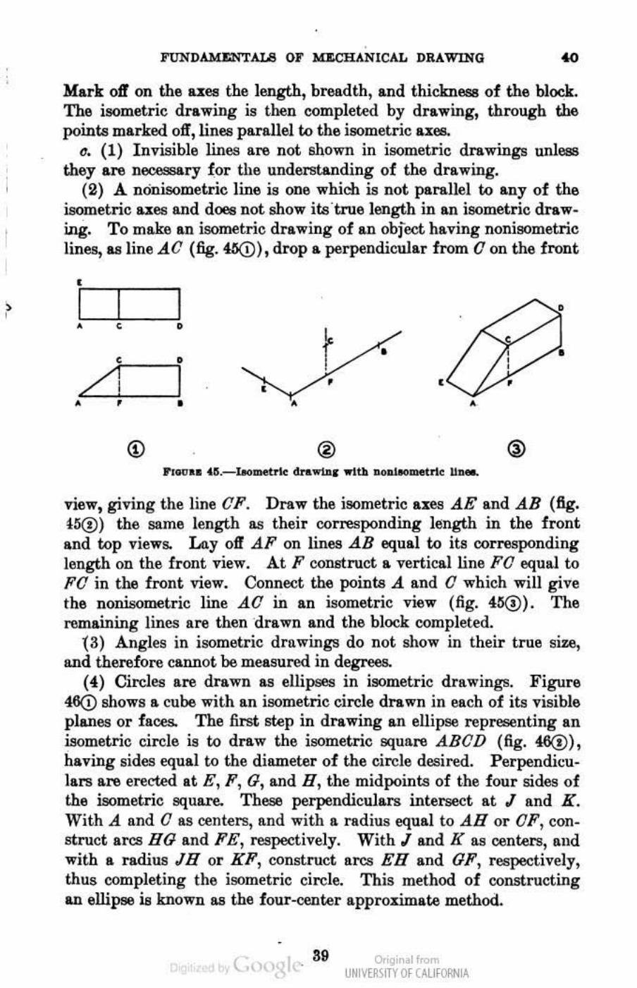
(2) A nOnisometric line is one which is not parallel to any of the isometric uea and does not show itsi true length in an isometric drawing. To make an isometric drawing of an obfect having nonisometric lines, as line..{O (fig. 41S(!), drop a perpendicular from 0 on the front
• I I I • , • r • , • /1 I • • • • • • • •
(j) ®
view, giving the line OF. Draw the isometric axes ,AE end ,AB (fig. t~) the same length as their corresponding length in the front and top views. Layoff.dF on lines .dB equal to its corresponding h.mgth on the front view. At F construct a vertical line FO equal to FO in the front view. Connect the points A and 0 which will give the nonisometric line AO in an isometric view (fig. 4;5@). The remaining lines are then drawn and the block completed.
(3) Angles in isometric drawings do not show in their true size, and therefore cannot be measured in degl e- s
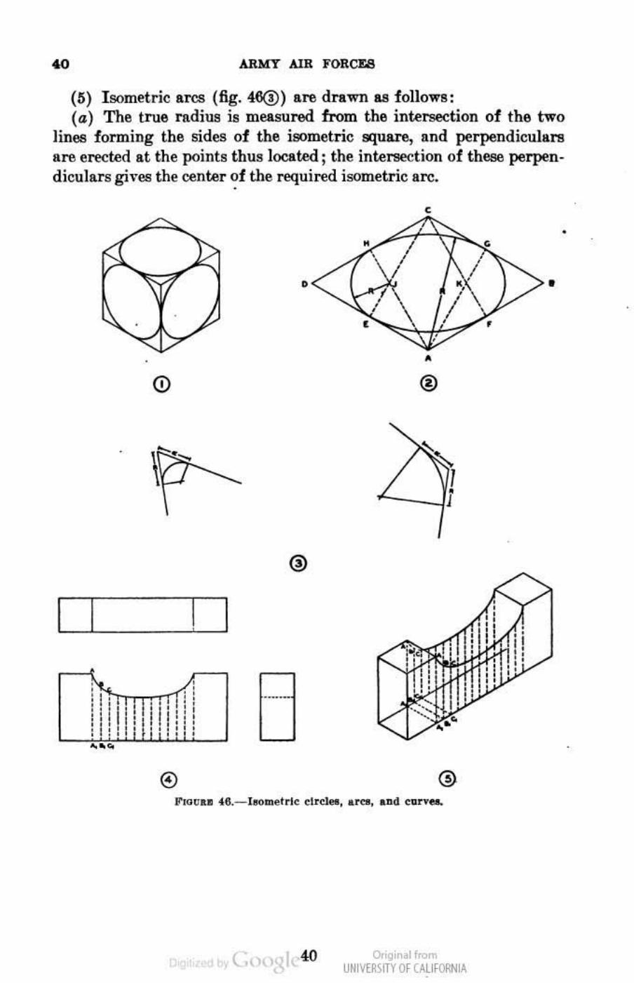
(4) Circles are drawn as ellipses in isometric drRwings. Figure 460 shows a cube with an isometric circle drawn in eech of its visible planes or faces.. The first step in drawing an ellipse representing an isometric circle is to draw the isometric square ABOD (fig. 46@), having sides equal to the diameter of the circle desired. Perpendil;ulars are erected It E, P , 0, and H, the midpoints of the four sides of the isometric !!qUare. These perpendiculars intersect It I Rnd K. With A and 0 es centers, and with a radius equal to AH or OF, construct arcs HO and FE, respectively. With land K aa centers, and with a radius In or KF, construct arcs En and OF, respectively, thus completing the isometric circle. This method of constructing an ellipse is known II!I the four-center approximate method.
( ., 39 o,'gir I< UNM~\fTY Of (AllfORNIA
ARMY AIR FORCUI
(IS) I sometric arcs (fig. 46(1) are drawn as 10llows: (a) The true l'lldius is measured 1rom the interseetion 01 the two
lines 10rming the sides 01 the isometric square, lind perpendicuhU''8 are ereded at the points thus located ; the intersection of these perpendiculars gil-es the center ~1 the required isometric IIrc.
•
<;)
I · /1 · TTl ' · I . . . • I " '. I lilT. Iii';' :1:·1: "I::: · .' ... ".
(
,
./ • ®
- _i
o,'gir .1",,", UNM~\fTY Of (AlifORN IA
•
• •
•
FUNDAMENTALS OJ' MECHANICAL DRAWING
(b) The radiUll of the isometric are is the length of the perpendicular to the point of intersection.
(6) Isometric curves other than circles are drawn by first locating a number of points on an orthographic projection (fig.46@). These points are then ttanllferrOO to the isometric drawing (fig. 46®), snd the curve drawn through these points.
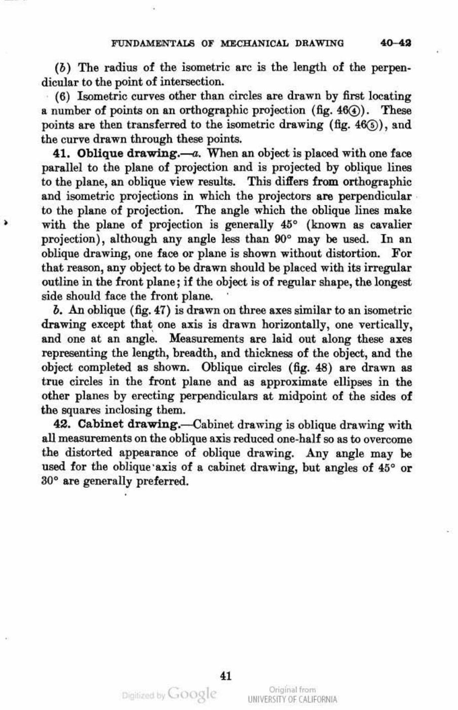
41. Oblique drawing.---a. When an object is placed with one face parallel to the plane of projection and is projected by oblique lines to the plane, an oblique view results. This dift'ers from orthographic and isometric projections in which the projectors are perpendicular to the plane of projection. The angle which the oblique lines make with the plane of projection is generally 46° (known lUI cavalier projection), although any angle less than 00° may be used. In an oblique drawing, one face or plane is shown without distortion. For that reason, any object to be drawn should be placed with its irregular outline in the front plane; if the object is of regular shape, the longest side should face the front plane.
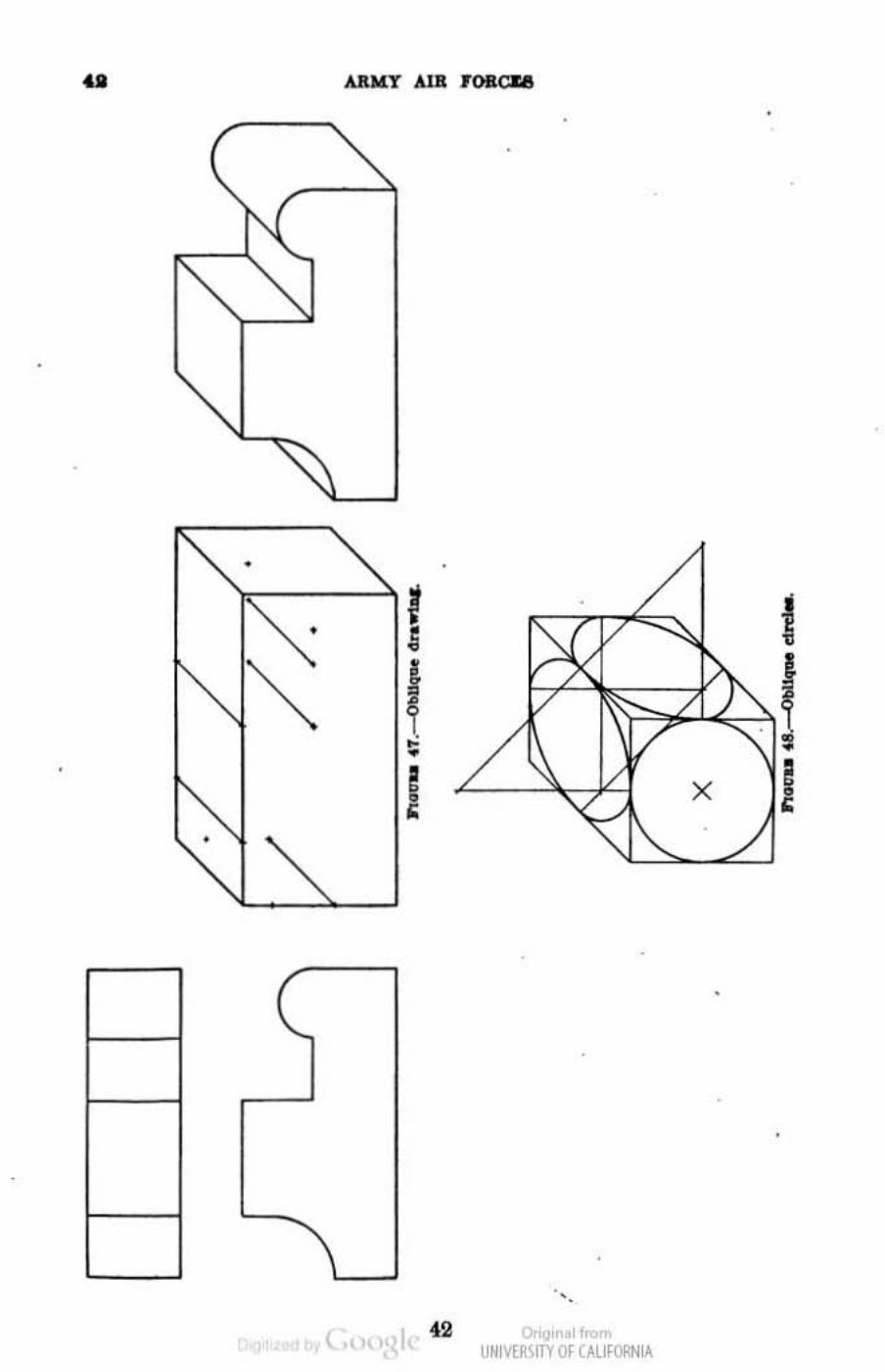
b. An oblique (fig. 47) is drawn OD three all:e8 similar to an isometric drawing except that one uis is drawn horizontally, one vertically, and one at an angle. Melll!uremenl$ are laid out along these uea representing the length, breadth, and thickness of the object, and the object completed as shown. Oblique circles (fig. 48) are drawn Ill!
true circles in the front plane and Ill! approll:imate ellipses in the other planes by erecting perpendiculars at midpoint of the sides of the squares inclosing them.
42. Cabinet drawing.-Cabinet drawing is oblique drawing with all measurements on the oblique nis reduced one-half so as to overcome the distorted appearance of oblique drawing. Any angle may be used for the obJique 'uis of a cabinet drawing, but angles of 415 0 or 300 are generally preferred.
41 ( Or,g" . 1 """'
UNM~\fTY Of (AllfORNIA
•
.. ARW:T AlB ,oacu
•
•
42 c. ~ U~IV[~IfTV Of UUfORN lA
•
FUNDAMU,"TALS OF MECHANICAL DRAWINO . 8
SECTION VII
SECTroNAL VI EWS AND THREADED P ARTS • P ........ pb
Sectional vleWll_____________________________ ________________ ____ ____ 43 Threaded parla___________________ __________ ___________________________ ~
43. Sectional view8.--a. Frequently the usus.! views do not give a clear picture of the object. The difficulty generally lies with the invisible object lines, in which case a view into the interior of the object wouid help clarify the drawing. Such It view may be obtained by imaging enough of tbe exterior of the object removed to expose the internal construction. The type of ~tion is determined by the llII10unt of exterior removed.
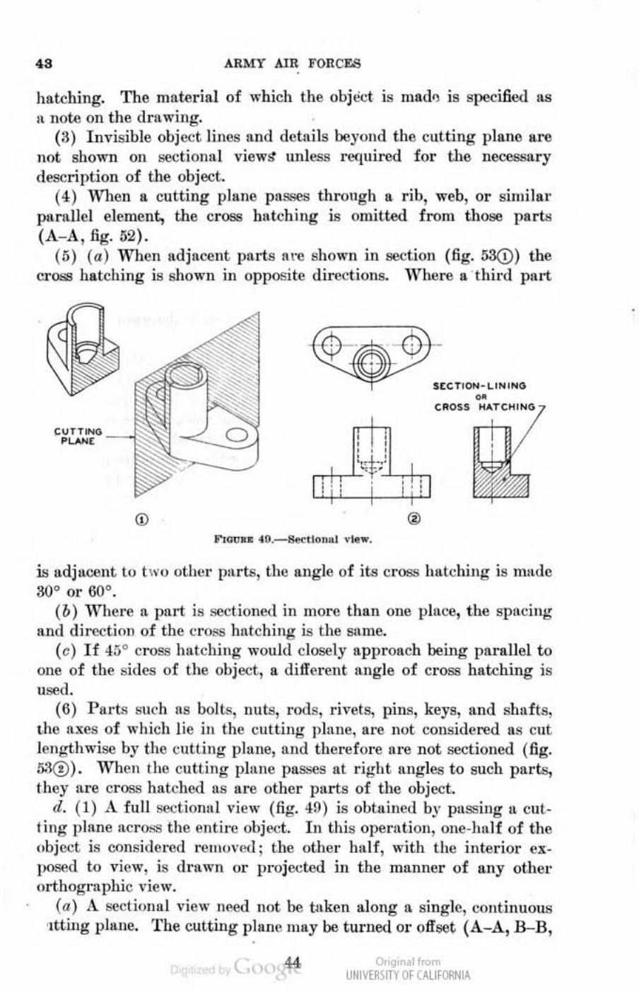
b. A sectional view (fig. 49) is obtained by imaging the obiect cut away, as it by 5awing. The path of the saw is considered the cutting plane, that is, the plane upon which the cut is made. If one portion of the object is then removed and a drawing made of the remaining portion, the lines formerly invisible are exposed to view. Since sectioning an object is an imaginary operation, the other necessary viefi's are not cbanged. The only addition is a cutting plane line, which t races the path of the cutting plane. A pictorial view of the object with the path of the cut traced by diagonal lines is shown in figure 49(!). An orthographic projedion with the side view ~tioned is shown in figure 490. The position of the cutting plane is locsted on the projected view by a cutting plane line. The view to be exposed after passing the cutting plane through the object is indicated by the direction of the arrows on the cutting plane line. WIlen the cutting plane line coincides with the center line representing the symmetrical axis of the object, the cutting plane line may be omitted.
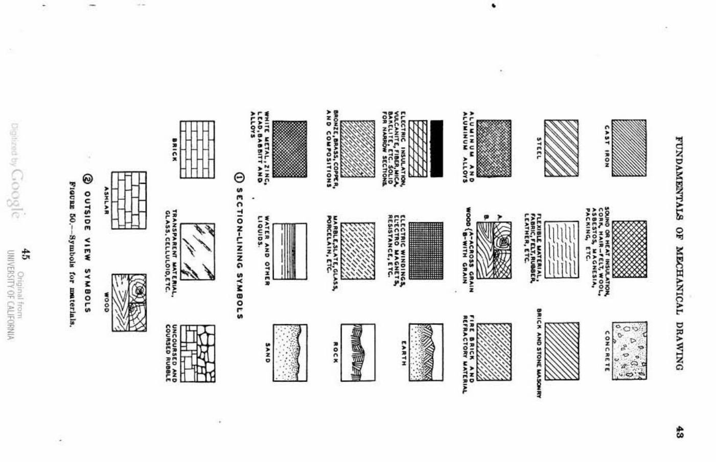
c. Uniformly spaced, M.i", fine, parallel lines, termed cross hatching or section.lining, are used to dist inguish surfaces of material theoretically cut and exposed by the cutting plnne. The spacing of cross hatching varies from %2 to % inch, depending upon the size of the drawing and the part. The symbols used to designate various materials in sectiollill view (and in olltside view) are shown in figure 00. The rules gOl'erning the use of symbols lind relllwd principles are as follows!
(1) Assembly drawing>! are cross hatched with the symbol representing the actual material of each part in the assembly. In figure!'H d i1J'erent materials are shoWJl-(:ast iron, babbit, bronze, and steel.
(2) Detail drawings are cross hatclled with the symbol for CIlSt iron regardless of tbe material used; this practice si.mplifies the cross
( is ar'gir I< UNM~\fTY Of (AllfORNIA
" ARMY AIR YOKeLS
hatching. The material of which the obj,ict IS mad!) is specified us 11 note 011 the drnwing.
(3) Invisible object lines nnd detllils beyond the cutting plane lire
not shown 011 section II ] view/t unles.'l required for the lIece8f!9ry
description of the object. (4) 'Vhen It cutting plane paS'!es throngh a rib, "'cb, or similar
parnllcl element, the cr08lj bRtching is omitted from those parts (A- A, fig. 62).
(5) (a ) When adjnccnt pnrts lire shown in seetion (fig. 53Q) the cross hatching is shown ill OPllOSi te directions. Where II third part
C" T nO<) _ _
Pu.H[ -
ncTOON-L'N'NG
CRon
is adjacent to two other pllrts, tlu~ angle of iti! cr O&! hatching is mude 30" or 60°.
(b) '''hel'c 11 pllrt is sectioned in more than one piUL'e, the spacing and d in;ct iol) of the cross hutching is the smile.
(e) If 45° cross hutching would closely approach being parallel to one of the sides of the object, a different angle of cross hatching is used.
(6) P arts such liS bolts, nuts, rods, rivets, pins, keys, lind shafts, Ihe lIxes of which lie in the eulting plane, 111"6 not considered u.s cnt lengthwise by the cut ting plane, and therefore ore not sect ioned (fig. 5.1@). 'Vhen the cutt ing plnne pllsseS nt right lIngles to sneh parts, they lIrc cross hatclled as are other parts of the object.
(I. (1) A full seetional view (fig. 49) is obtllined by passing U CiIl· ling plalle across the entire object. I n this operation, one-half of the object ia considered N.!!lJO\·L.J; the other hull, with the interior exposed to view, is druwn or p l"Ojecl.ed in the munner of any othel" orthographic view.
(a ) A sectionul "iew Ileed not be tuken along n single, continuous ,ttting pillne. The cutting plane Illlly be turned or offset (A- A., B-B,
~ " UNIVERSITY Of CALI fORNIA
•
~ • --~ t; , '< ~~.
if >
."' • 0 o 0 , . • 0 ., " • < , " < • • , ! •
• • • • o " •
• , , •
e • " • • o , , • • o
; • o " •
•
_,".0'»', • • o , . • -
~
~ ~
~ o ~
~
• •
.. ARMY AIR TORCr.s
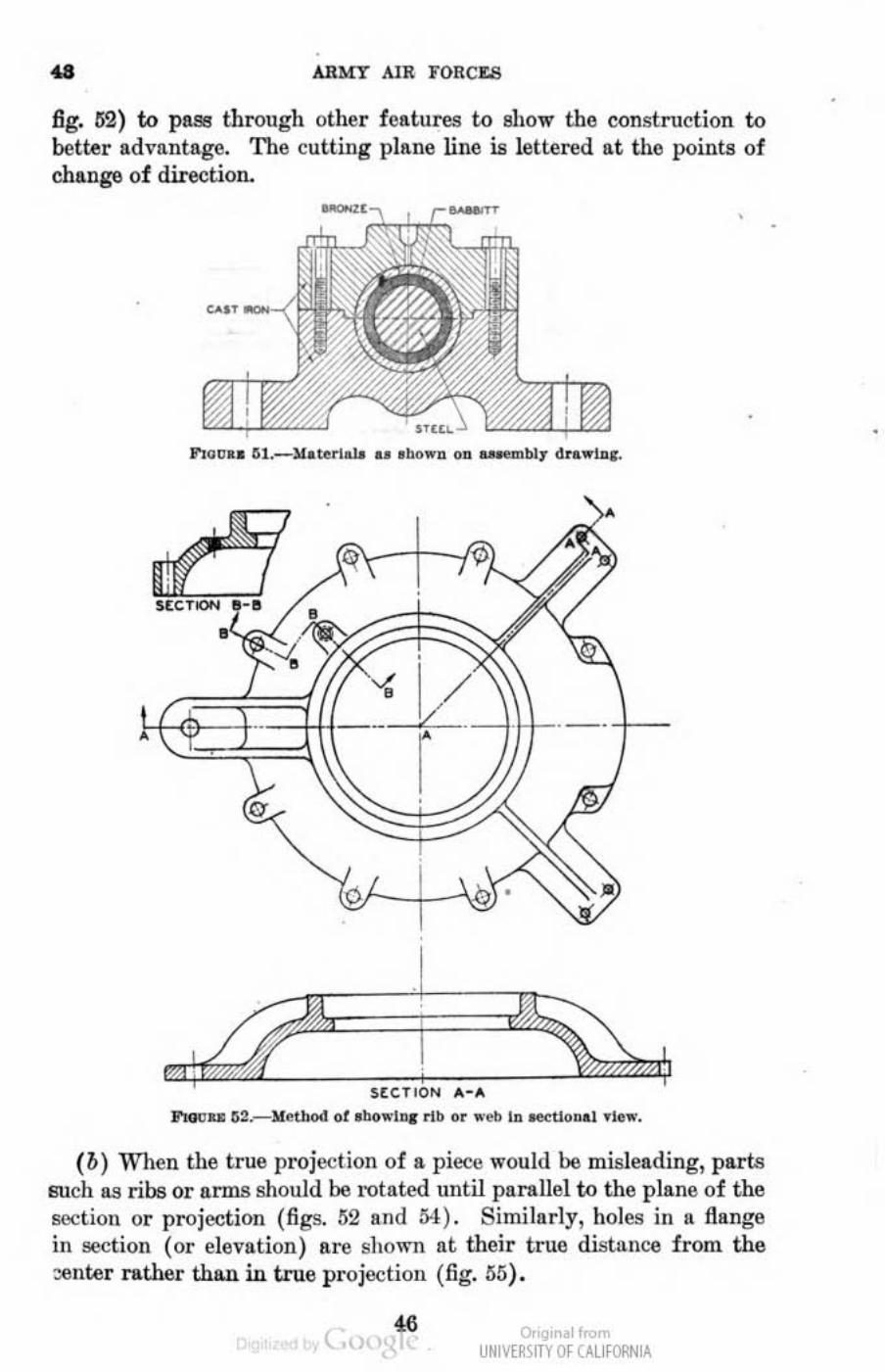
fig. 62) to pass through other features to ahow the construction to better ad\·nntagc. The cutting pI /me line is lettered at the points of change of direction.
0-0
J'tovu ~2.--loIet_ ot Ibo"'Lnr flb ..... -eII In _1>0.1 .1 .....
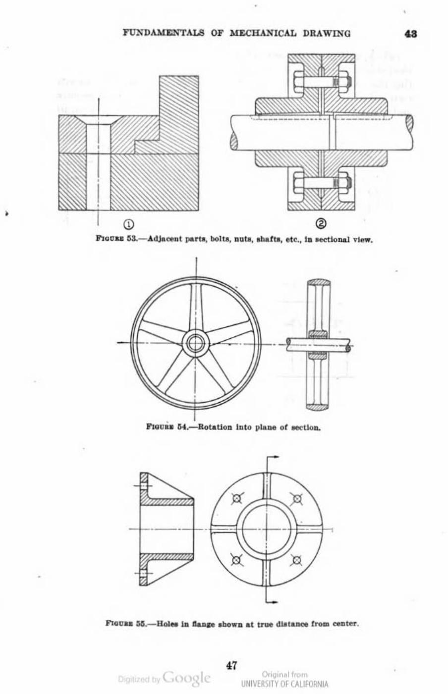
(b) When the true projection of a piece would be misleading, parts w eh as ribs or prInS should be rotated until parallel to the plane of the !;OCtioll or projectioll (Jigs. 52 lind 54). Similarly, holes ill a flange ill l!eCtion (or elevation) Rrc shown at their true distance from the :xlilter rather thQ.D in true projection (fig. 55).
'" O. 1<.
UNIVERSITY Of CALI fORNIA
•
(,
®
0". ~.I" '" UHIV[~IITY Of (,\,llfORHIA
• ..
•
.. A1W:Y AlR F()RCr.e
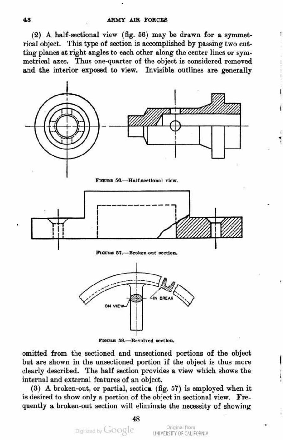
(2) A balf-sectional view (6g. lI6) may be drawn for a symmetrical object. This type of section is accomplished by passing two cutting planes at right angles to each other along the center lines or symmetrical lI.l:eB. Thus one-quarter of the object is considered removed and th& imerior e:a:poeed to view. Invisible outlines aro generally
I'IDtt .. 6II.-llalt...et1oul .Ie • .
r-------------,
omitted from the sectioned and unsectioned portions of the object but aN.! shown in the unsectioDed portion if the object is thus more clearly descr ibed. The half aeclion provides a view which shows the internal and e.xternal features of an object.
(S) A broken-out, or partial, sectioa (fig. 117) is employed wh611 it is desired to show only II. portion of the objoct in sectional view. Frequently a broken-out section will eliminate the necessity of showing
48 ( o,'gir I<
UNM~\fTY Of (AllfORNIA
•
I I
1
I • I
FUNDAME~'TALS OF MECllANlCAL DRAWING 4 3 - 4.4
It. full or halt-sectional view. T he broken-out section is bounded at the break by a shOl·t bl'eak line.
(4) A revolved section (fig. 58) is used to show cross sections of anns, apokes of wheels, brackets, etc. The section is obtained by passing n cutt illg plane perpendicularly timmgh the axis of the part and then revolving the sectioned portion one-quarter tUrll, showing the cross section 011 the longitudinal view. The revolved sect ion may be shown directly 011 the view or in It. break ill the view. .
(5) A detail section (B-B, fig. 5~) is shown at some convenient locRtiou on the paper, entirely separnt.e and remo\'ed from the regu lll. l· projected view. T he detll.il sect ion is located on the view by >l cutt ing plane line. III order 19 clarify the const ruction of small details,
(j) ®
this type of section is frequently drawn to a larger scale than the view on which the section is indicated.
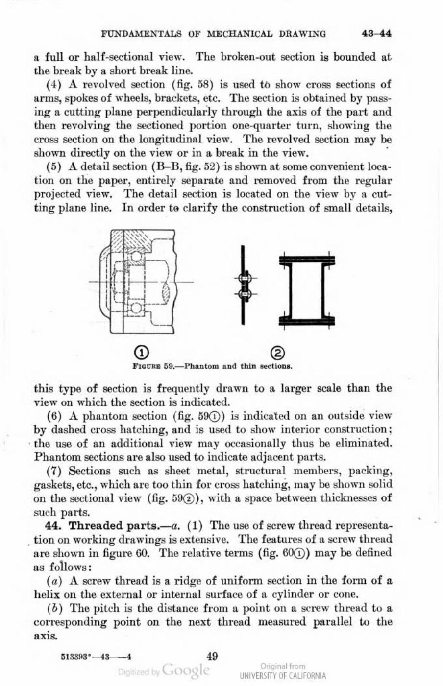
(6) A phantom se<;t ion (fig. 69(D) is indicall'(l on an outside view by dashed cross ha tching, and is used to sho\\' intel'ior construction ;
. tho use of all addi tional view may occasionally thus 00 eliminated. P hantom sections are also used to indicate Rdjll~lIt ports,
(7) Sections such us shcet metal, structural mcmi>ers, packing, gaske ts, etc., which al'e too thin for CI'OSS hll«:hing, may be SllOlI'lI solid on the sectional view (fig. 59(!), with a space bet Wl'Cll thicknesses of such parts.
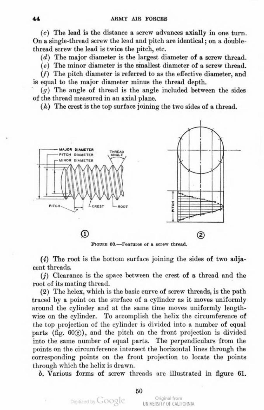
44, Threaded PlI.ris.--a, (1) The use of screw thread representa. tion 011 working d rawings is extensive. T he featnres of a screw lhreud
a re shown ill figure 00. The l'eintiv6 te rms (fig. 60;]) may be defined lIS follows :
(a) A screw thread is a ridge of uniform section in the i'OI,n of a helix 011 tile external or internal surface of a eyEndel' or cone.
(b) T he pilch is the distance f rom 11 point on n screw th r~ad to a COI'I'esponding point on the next tlll~ad measured parallel 1..0 the
• aXIs.
49 ~ " UNIVERSITY Of CALI fORNIA
,
•• ARMY AlR FORCES
(e) The lead is the distance II IilC rew adyances axially in OM turn. On II. shlgle-thread screw the lend lind pitch are identical j on a doublethread screw the lead is twice the pitch, etc.
(d) The major diameter is the largest diameter of II IICrew thread. ( e) The mi llor diallleter is the smallest diameter of a IICrew thread. (f) The pitch diameter is referred to liS the e1Tecti\'c diameter, and
is equal to the major diameter minus the th read depth. (q) 'n lC angle of thrend is the angle included between the sides
of the thread measured in an uxial plane. (A) The crest is the top surface joining the two sides of a thread.
® J'r~CII &O._ F,"UrM of •• e ..... tb ...... d.
(i) The root is the bottom surfllOO joining the Irides of two adja. cent threads.
(j) Clearance is the space between the crest of II thread and the root of its muting thread.
(2) The llelex, which is the basic cun 'c of screw threads, is the path t ruced by a point on the b"llr facc of a cylinder as it moves uniformly around the cylinder and at the SlIme time mo\-es uniformly lengthwise on the cylinder. '1'0 accomplish the helix the circumference of Ihe top projection of the cylinder is divided into !I number of equal parlll (fig. 60(!), and the pi tch on the front projection is divided into lhe same number of equal parts. The perpendiculars f rom the points Oil the circumference illlerseet the horizontal lines through the correspond ing points 011 the f ront projec t ion to locate the points through wllich the helix is drawn.
b. Various forms of screw ul reads nrc ilIuslrated in figure 61.
". ~ " UNIVERSITY Of CALI fORNIA
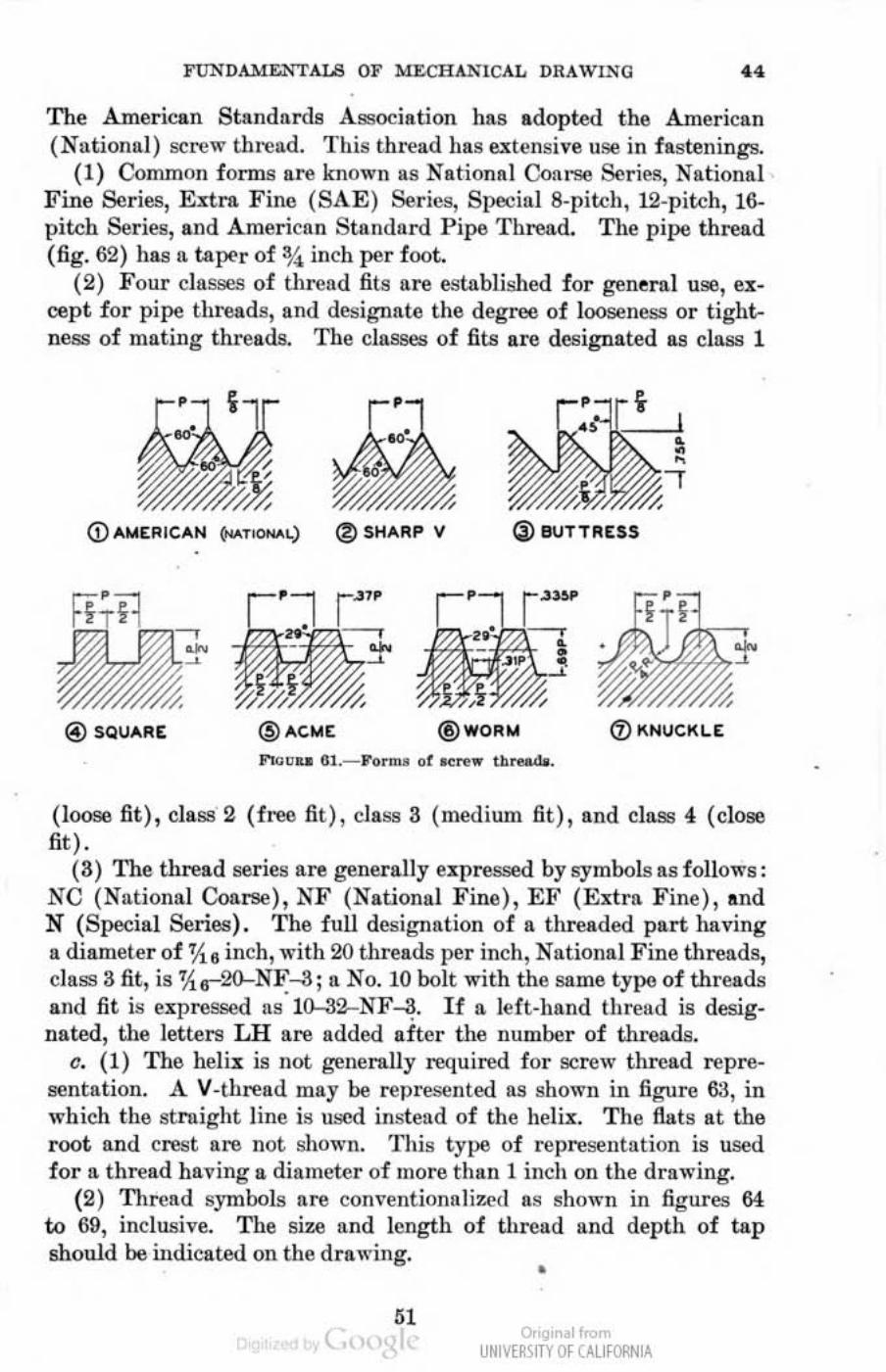
FUNDAMENTALS OF MECHANICAL DRAWDIO .. The American Standards Association has adopted the American (Nationul ) screw thread. This thread has extensive use in fastenings.
(1) Common fOnDS are known as Nationd Coarse Series, Nationd F ine Series, El:trn Finl! (BAE) Series, Special 8-pitch, 12-pitch, 16· pitch Series, and American Standard Pipe Thread. The pipe thread (fig. 62) has n taper of %. inch per foot.
(2) Four classes of thread fi ts are established for generol use, ucept for pipe threads, and designate the degree of looseness or tight. ness of mating threads. The cJaMes of fits are designated as class 1
(j) BUTTRESS
® SQUARE @ACME ® WORM
F"m .. 6t.- Von\>. 01 .. ..., ... tb"-.
(loose fit), class 2 ( free fit ), claM 3 (medium fit), and class 4 (close fit) .
(3) The thread series are generally upressed by symbol.s 8080 follows: NC (Nalional Coarse), NF (National Fine ), Eli' (El:tra Fine) , and N (Special Series) . The full designation of a threaded part having a diameter of % 8 inch, with 20 tllfeads per inch, National Fine tllreads, class 3 fit, is %r2Q.....NF....a; a No. 10 bolt with the same type of threads and fit is expressed liS 10-32-NF~. If a left-hand thread is designated, the letters LH are added after the number of threads.
c. (1) TIle heli.ll is not generolly required for screw thread representation. A V -thread may be represented as shown in figure 63, in which the straight line is used indead of the helil:. The flats at the root and crest are not shown. This type of representation is used for a thread having a diameter of more than I inch on the drawing.
(2) Thread symbols are cOln·entiona1i7.cd as ~hown in figures 64 to 69, inclusive. The size and length of throad and depth of tap should be indicated on the drawing.
" •
Or", •• 1 I<om UNIVERSITY Of CALI fORNIA

.. ARMY AIR FORCEa
(a) Regular external thread 8)'1110018 recommended for general use 011 assembly lind detail d l'awings ure sJlOWIl in figure 64. Other than external threads in sect ioual "jew, the creS18 lind roou. of threads are shown liS aiterllllte long lind short lines pE'rpendiculnr to the Illtis. These lines may be of equnl weight or the root line may be heavier.
0.0J,0.. ~ PIPe -,
,,"~un G2._PI~ ,h...,.d .
I
•
· .. .. . .. .' ", · ...... , , , . -i.~ : ' \ 'I · ...... ', - ~ · .... . •
F100u et.-II<sulu ., .. bolo fo ' eue. uol 1!' ...... d •.
S pacing of root lind crest lines need not be IIClIled but may be judged by eye to look well.
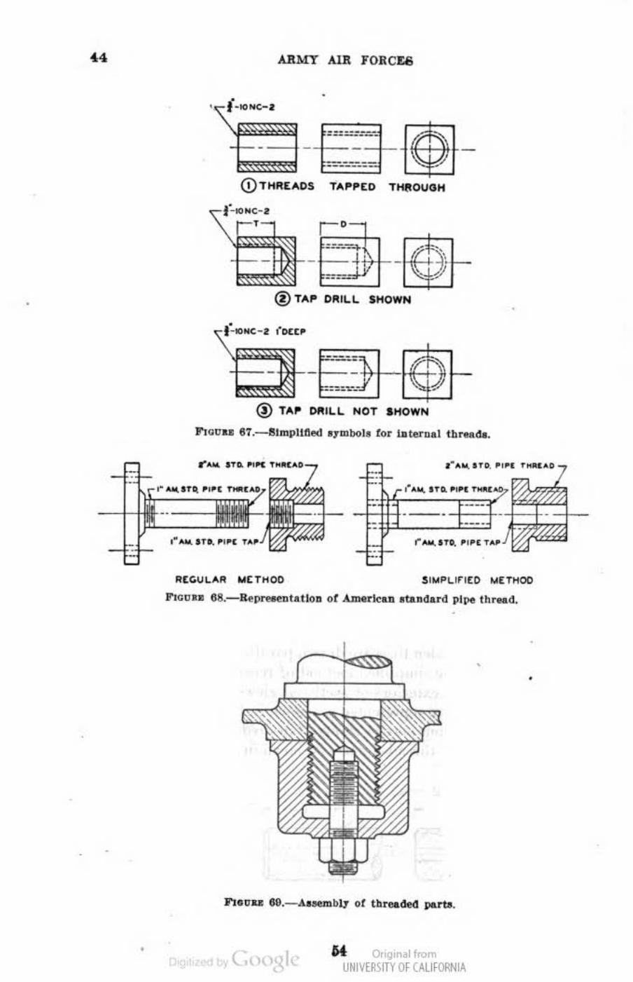
(b) Regular internal thread symbols lire sho" 'n in lignl-a 65. 1. When the threads are tapped through, the representation IS
liS shown in figure 65@. f. 'Vhen the poi]}!. of the l ilp d r ill does not extend tlu-ougll the
(nut, the\-epresentB.tion is as in figure MC!>.
~ " UNIVERSITY Of CALI fORNIA
•
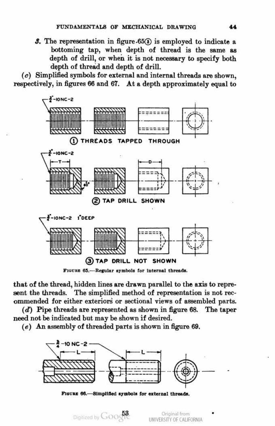
FUNDAMENTALS OF r.a.cRANICAL DRAWING •• 4. The representation in figure.6!S@ is employed to indicate a
botroming tap, when depth of thread is the same 8.9
depth of drill, or when it is not necessary ro specify both depth of thre&d and depth of drill.
(e) Simplified symbols for external and internal threw are shown, respec.:tively, in figures 66 and 67. At a depth approximately equal ro
CD THREADS TAPP[O THROUGH
•
® TAP ORILL SHOWN
• •
@TAP ORILL NOT SHOWN
that of the thread, hiddilD lines are drawn parallel to the axis to represent the threads. The simplified method of representation is not recQrnmended for either exteriorS or sectional views of 8.S!Iembled puts.
(d) Pipe threads are represented as shown in figure 68. The taper nood not be indicated but may be shown if desired.
(e) An assembly of threaded parts is shown in.figure 69.
-IO NC-2
( o,'gir I< UNM~\ITY Of (AllfORNIA
•
" ARMY AUI FORC1:8
•
@ TA~ I)III ILL I< OT
""au .. e1._elmplll'l<!d 01mbol' tor lu.rDol I b_(le.
~[C.u"AII "[T"oo
•
• U Or I< UNIVERSITY Of CALI fORNIA
I'UNDAMJ:.NTALB OF MECHANICAL DRAWING .0-" SIlCTIOlt VIlI
SCALES, DIMENSIONS, AND NOTES Pan.".P~ SctUe of d~~n .. ________ ________________________________________ ____ ~
~~&-______ ~_____________ ____ _____ ________ _______ ____________ +G Notel________________ __ _____________ ________________________________ 47
45. Beale of drawings.-a. (1) Objects are drawn full size when the details thereof are clearly shown and the size of the paper will conveniently permit.
(2) Enlarged drawings of views or sectio1\8 are made when the actual size of the object is 90 sman that full-size representation would not clearly present the featuree of the object.
(8) Reduced-acale drawings are mads of large objects that can be shown clearly in the smaller seale. The prime object in reducing the ac&!e of drawings is to reduce the sir.e of the drawing; therefore, as sman ... shllflt, is usd as is practicable without crowding the views. The eeale of drawings should not be reduced to such lUI enent that sectional views, notes, or tabulations C&nnot be added. Considerable clear space should &!ways be left below the change block for the enlargement of this block.
b·. (1) The scale of a drawing is generally noted in the title block:. When all views on a drawing axe actual size the scale may be stated as "Full size"; in some practioe, when the object is drawn full si:r.e the scale is not shown.
(2) When one or more views or sections are enlarged the notation "Enlarg&l view" or "Enlarged section," as the ease ma.y be, is placed under the enlarged representation.
(3) (a) When all views are in the same reduced scale, the 8C&i1l is noted in accordance with such reduction, as "One-halt si:r.e," or 6"- 1'.
(b) When the main views are in one reduced scale and other views or sections are in another eeale, each view or group of views has its own eeale shown.
46. Dimenalona.-a. (1) Information as to the shape of the object is provided by the various views on the drawing. These shape reprellOOtations must have dimensions applied to the various features to indicate the 6ize of the object. Dimensions, as given, refer to the actual sir.e of the object ro be constructed, regardless of the ecale to which the drawing is made . . (2) A drawing must be so dimensioned that the par1.lJ: shown thereon
ean be made without necessity of scaling the drawing . . Dimensions should not be duplicated on variOUl! views or on a single view except
( o,'gir I< UNM~\fTY Of C'.llfORNlA
-
•
•• ARMY AI R FORCM
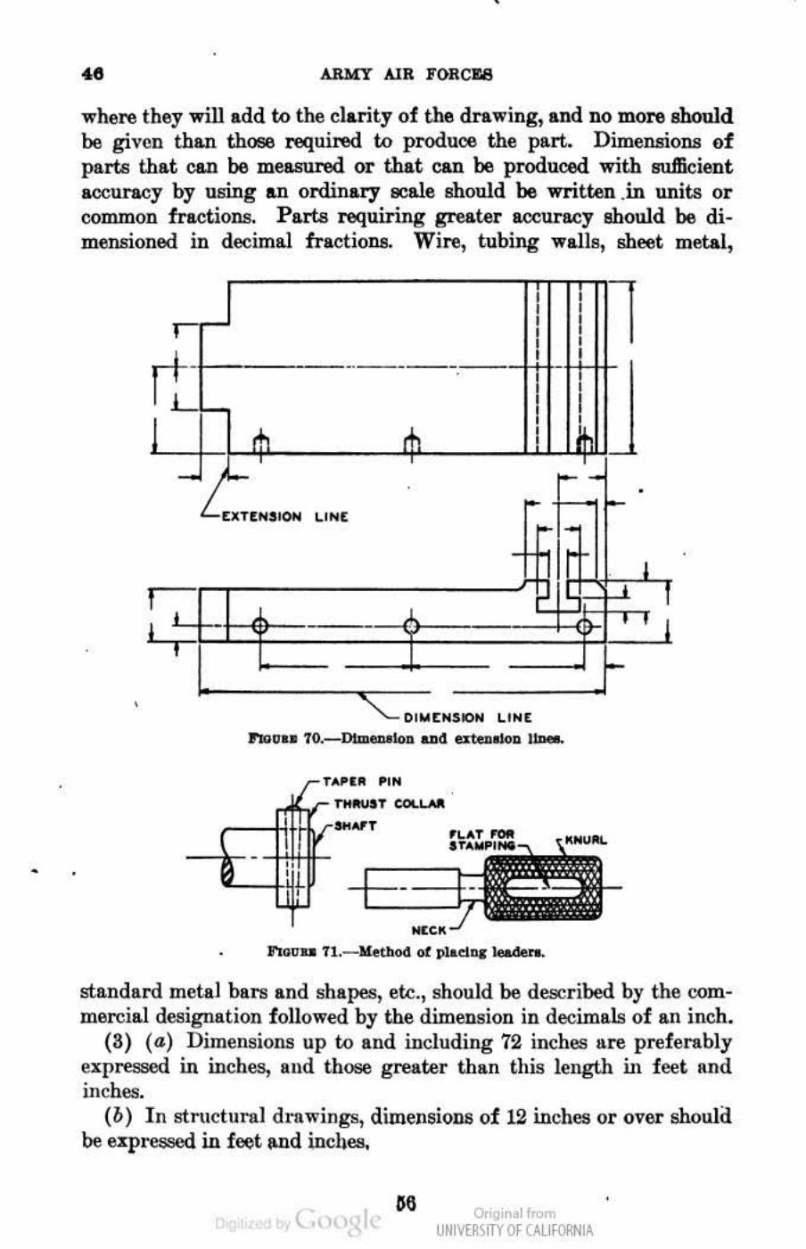
where they will add to the clarity of the drawing, and no more should be given than those required to prodU08 the part. Dimensions of parts that can be measured or that can be produced with sufficient accuracy by using an ordinary scale should be written .in units or common fractions. Parts requiring greater accuracy Bhould be dimensioned in decimal fractions. Wire, tubing walla, shoot met.I,
, , l , I , , , , ,
ft- , , -- - - -- ,
I
L+,-¢. ..u lip! - •
EXUH!IOH I.I N (
rrl1 ~
I
f L
~ -Q- :',j;:f-' :
• • DI EtlSION LI [
1'»0 •• 1o._ Dlmen'''''' ... 4 atelloloa 11-.
... -, COl. ........
"'00 .. 7l.-lIIetllocl 01 plAd ... '00+ ...
~
standard metal bal"!! and shapes, etc., should be de9Cribed by the commercial designation followed by the dimension in decimals of an inch.
(3) (al Dimensions up to and including 72 inches are preferably express~ in inches, and those greater than this length in fed Rnd inches.
(b ) In structural drawings, dimensions of 12 inches or over should be ezpreescd in foot Md inches.
c. " Or.gi,.I",,", UNM~\fTY Of (AllfORNIA

l"UNDAMEJ',"'TALa OF M£CHANlCAL DRAWING .. (e) In automotive, sheet metal, and some other practices, all di.
mensions are specified in incbfl!! (d) When all dimensions are given in inches, the inch symbol (n)
is preferably omitted. A note may be placed on the drawing stating that all dimensions are given in inches.
b. (1) A dimension line is broken near the center for a sufficient space to permit in .... rtion of the dimension.
(2) Arrowheads on dimension lines are drawn approximately % inch long and about 1h as wide.
(8) Wherever convenient, dimension linM are located outside the view of the object repi .£"inted, approIimately % inch from the outline of the drawing and other dimension lines. Where a dimension is placed within II. sectional view, the cross hatching is kept clear of the dimension numeral.
(4) A center line should never be used as a dimension line. A
line of the part illustrated or an extension of such line should not be used as a dimension line.
(6) EItension lines are employed when the dimension is located: outside the view. EJ:tension lines are drawn approximately %2 to l,Ila inch away from the outline, and extend appro:rimately ItS inch beyond the arrowhead of the dimension line (fig. 70).
(6) Leaders, which are lines drawn from dimensions or notes to indicate their application (fig. 71), are of the same weigbt as di. mension lines and are terminated. by arrowheads at the drawing; leaders should not be curved nor made freehand.
c. (1) A dimension line should not pass through a dimeJlllion numeral. If unbroken lines are used, as is common practice in struc·" tural drawing, the dimensions are praced above the line (fig. 72).
(2) Dimension lines and their corresponding numerals should be placed 80 that they may be read from the bottom or right-hand edges of the drawing (fig. 730). When fradional dimensions of less than 1 inch are given, the numerator should be placed above the dimension line and the denominator below. Where the fraction is part of l\
numeral, the division bar of the fraction is placed in line with the dimension line. All dimensions should be placed so as to fllad in the direction of dimension lines (fig. 73(!). The practice with respect
( o,'gir I< UNM~\fTY Of (AllfORNIA
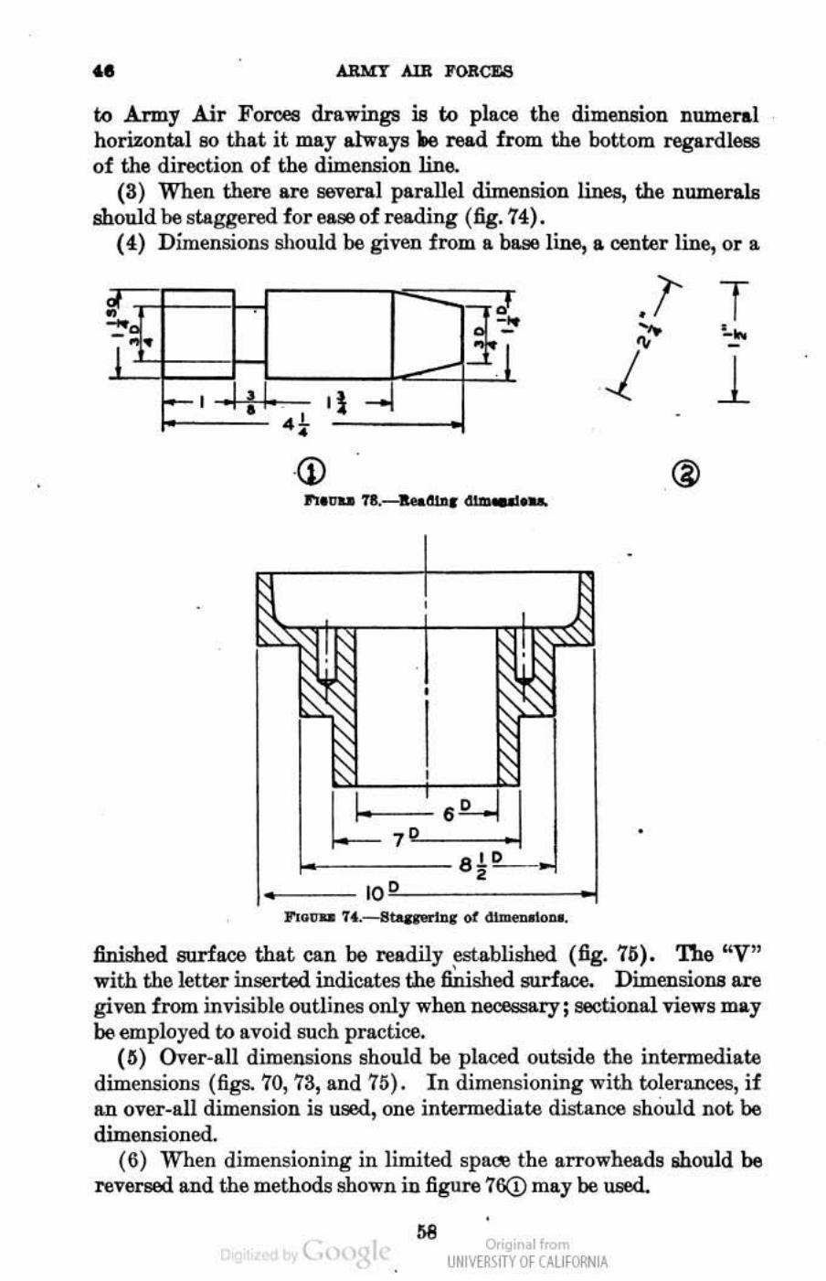
•• ARMY AlB FORCE8
to Army Air FOr0e8 drawings is to place the dimension numeral horizontal 80 that it may always J,e read from the bottom regardJe!18 of the direction of the dimension line..
(3) When there are several parallel dimension lines, the numerals should be staggered for ease of reading (fig. 74).
(4) Dimensions should be given from a base line, a center line, or a.
t .1 i I . '1-1
(j)
7 •
• _ __ 10
no" ... H.--.II!.a,ftfIrlnc of ~ ....
finished surfaoo that can be readily established (fig. 71S). 'The "V" •
with the letter inserted indicates the finished surfaoo. Dimensions are given from invisible outlines only when necessary; sectional views may be employed to avoid such practice.
(IS) Over-all dimensions should be placed outside the intennediate dimensions (figs. 70, 73, and 75). In dimensioning with tolerances, if RJl over-all dimension is used, one intermediate distance should not be dimensioned.
(6) When dimensioning in limited spare the arrowheads lihould be reversed and the methods shown iu figure 76Q) may be med.
" ( o,'gir I< UNM~\fTY Of (AllfORNIA
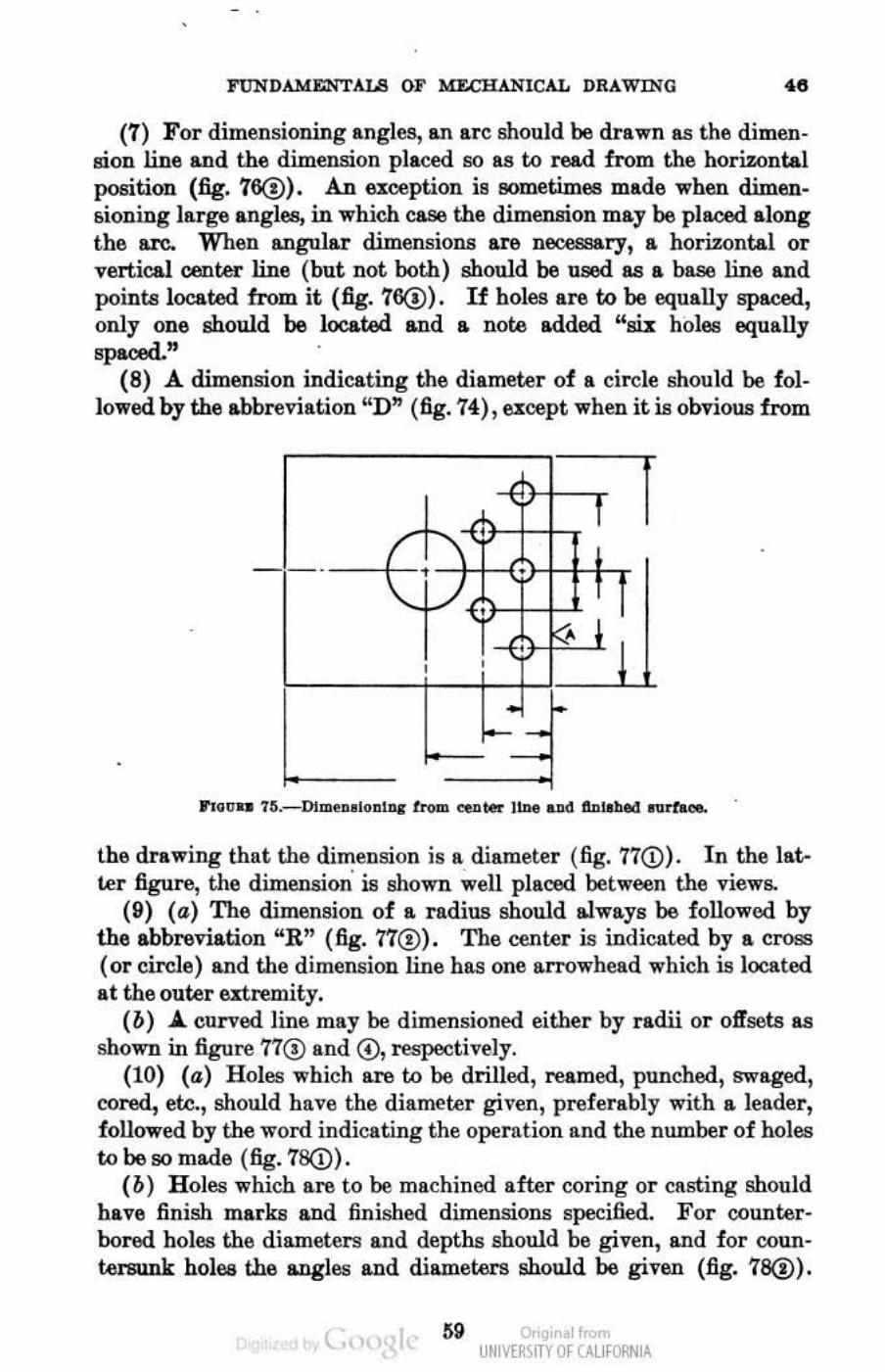
FUNDAMENTALS OF M:£CHANICAL DRAWING •• (7) For dimensioning angles, an are should be drawn as the dimen
sion line and th(l dimension placed &0 as to read from th(l horizontal position (fig. 16@). An exception is 80metinlElS mad(l when dimensioning lar~ angles, in which C&86 the dimension may be placed along the are. When angular dimensions are necessary, a horizontal or nrtical oont.er line (but not both) should 00 u.ood as a base line and points located from it (fig. 76(!). If holes are to be equally spaced, only one should be located and a note added "w: holea equally spaoed. "
(8) A. dimension indicating the diameter of a cil'Cie should be followoo. by the abbreviation "D" (fig. 74), except when it is obvious from
the drawing that the dimension is a diameter (fig. 77<D) . In the latter figure, the dimension' is shown well placed between the views.
(9) (a) Th(l dimension of a radius should always be followed by the abbreviation "R" (fig. 71®) . The center is indicated by a cross (or circle) and the d imension line has one arrowhead which is located at the outer extremity.
(b) .A. curved line may be dimensioned either by radii or offsets as shown in figure 770 and 0. respectively.
(10) (a) Holes which are to be drilled, reamed, punched, swaged, cored, ei.e., should have the diameter gifen, preferably with a. leader, followed by the word indicating the operation and the number of holes to be so mad(l (fig. 18(D) .
(b ) Holes which are to be machined after coring or casting should hlilve finish marks and finished dimensions specified. For counter· bored holes the diameters and depths should be given, Illld for countersunk holes the .ogles and ditune1:er8 should be given (fig. 18(!).
( 59 Or'gir I.-UNM~\fTY Of (AllfORNIA
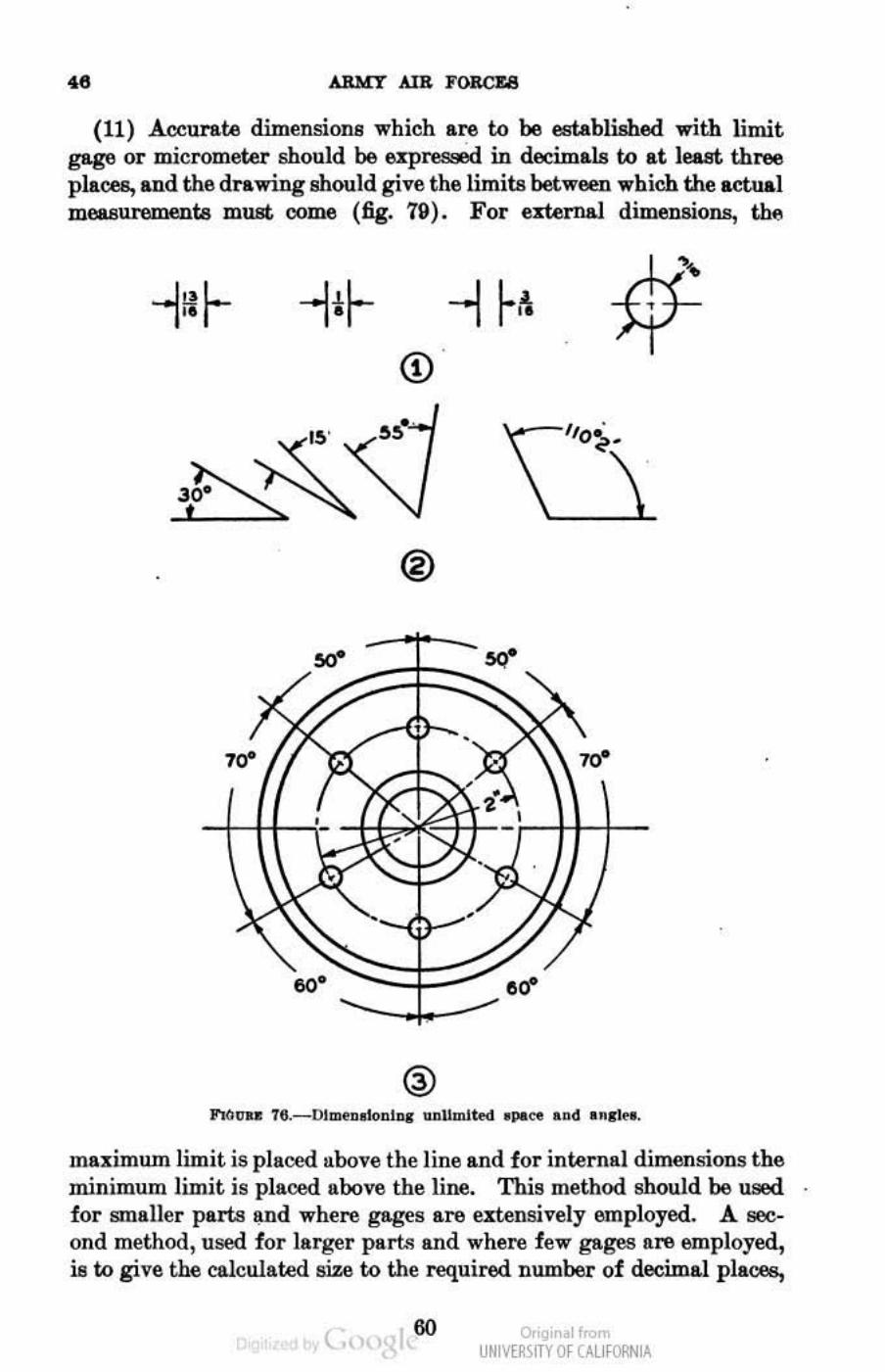
.. A.RMY AI8 :YORCU
(11) Accurate dimensioDs which are t.c be established with limit gage or micrometer should be UJlN 3. -d in decimals to at leut three places, and the drawing should give the limite between wbich the actual measurements must oome (fig. 79). For external dimensions, t.llil
<D
®
00- ,,'
maximum limit is placed above the line and for internlll dimensions the minimum limit is placed above the line. This method should be WE Ii for smaller parts I!.nd where gages are extensively employed. A second method, used for larger parts and where few gages are employed, is to give the calculated size to the required number of dooimaJ places,
( 60 o,'gir I< UNM~\fTY Of (AllfORNIA
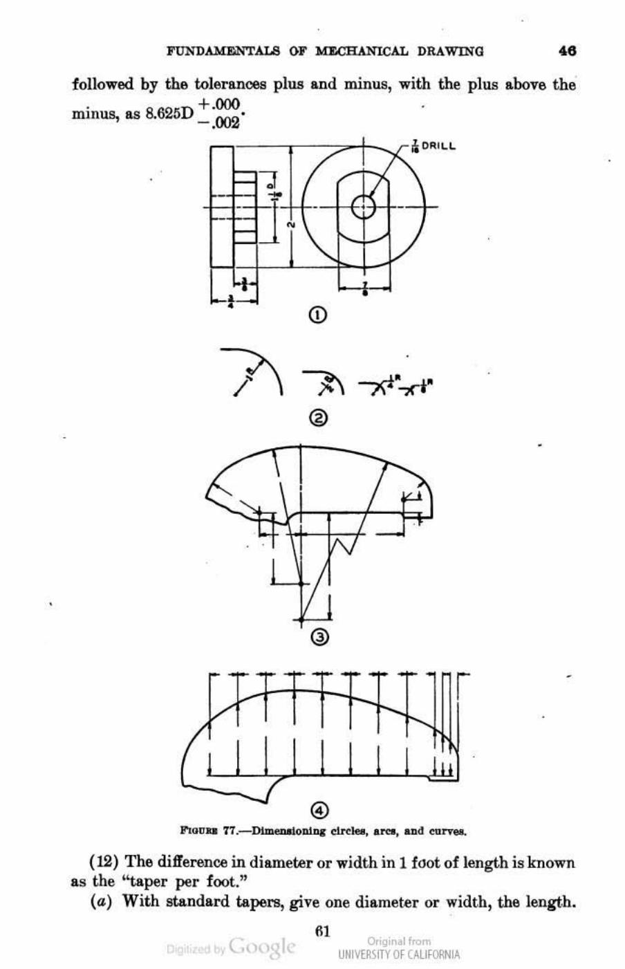
I'm'i'DAMEiNTALS GJ' Ia.CHANlCAL DRAWlNG •• followed by the tolerances plUli and minus, with the plUli above the
minus, as 8.625D +::.
(j)
r
(12) The difference in diameter or width in 1 foot of length is known as the "taper per fool."
(a) With standard tapers, give one diameter or width, the length.
"' ( o,'gi. I< UNM~\fTY Of (AllfORNIA
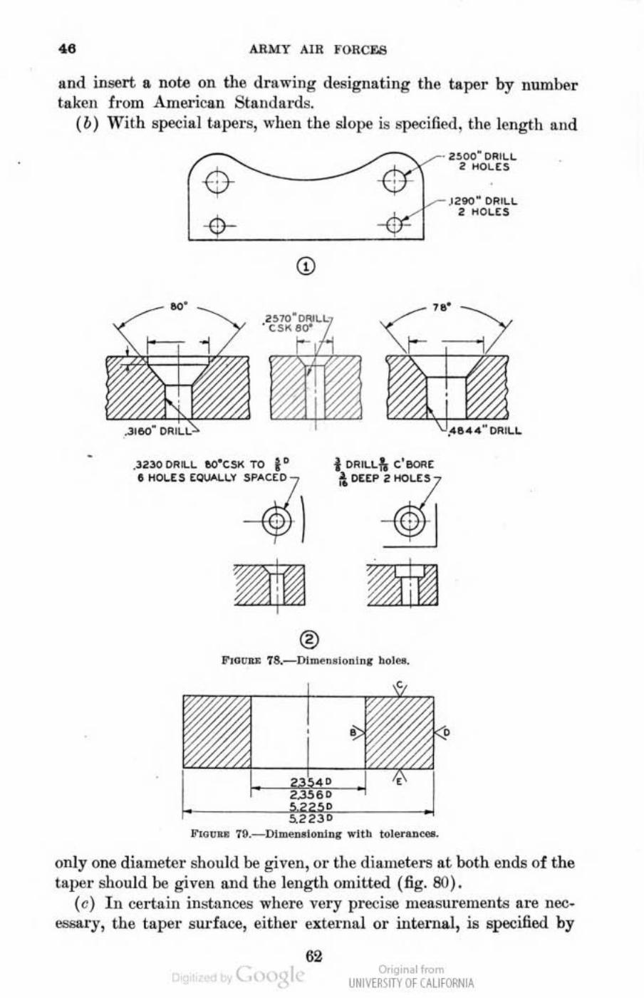
4. ARMY AIR FOReY..,
lind insert a nole on the drawing designating the taper by number taken from American Stllndal-ds.
(b) With special tapers, when the slope is specified, the lenglh and
~ .
.3230 ORl.L IIO"GSI< TO to & HOU S to\.loOU.V sp"c(t)
®
. noo' DRILL 2 OiOUS
___ )210" DRILL 2 HOLES
f ORILL& C'IIOfI( ;\ PUP 2 HOLES
l"Ioou: 18._0l ""'QOloolnlJ bolo..
1I'l(l0'" 19._DlmeDolonlor .. Itb toler .......
only one diameter should be given, or the diameters at both ends of the laper should be given and the iengtll omitted (fig. SO) .
(e) In certuin instances where very precise measurements are noo· IlSI;Ilry, the taper surface, either external or internal, is specified by
62 ~ " UNIVERSITY Of CALIfORNIA
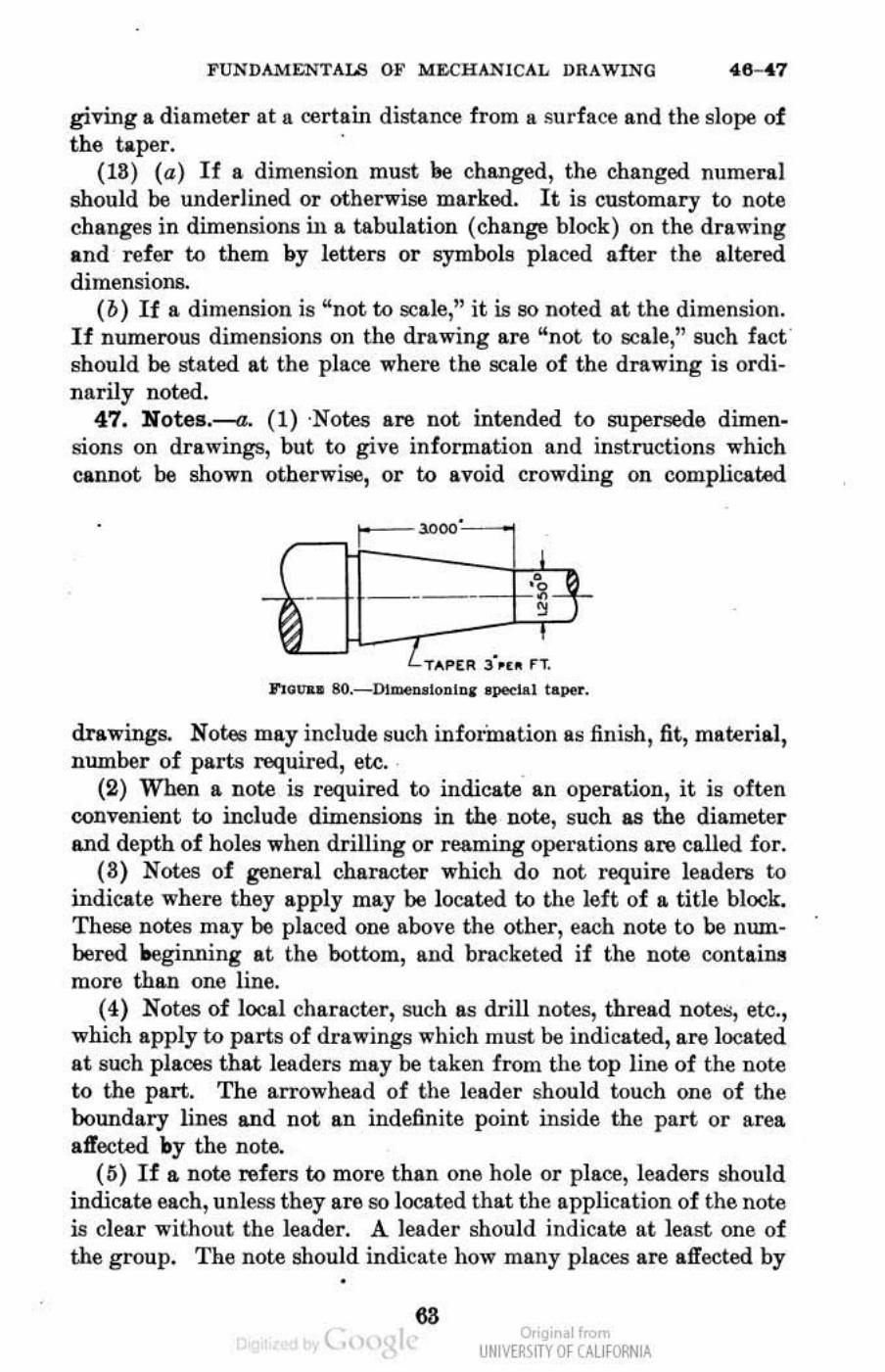
FUNDAl'oI&NTAUI OP M&CHAN1CAL DRAWING '116- '117
giving a diameter at a certain distance from II surface and the slope of the taper. .
(IS) (a) If a dimension must 00 changed, the changed numeraJ should be underlined or otherwise marked. It is customary to note changes in dimensions in a tabulation (change block) on the drawing and reler I:{) them by letters or symbols placed after the altered dimensions.
(b) If a dimensiOll is "not to scale," it is so noted at the dimension. If numerous dimensions on the drawing are "not to scale," such fact should be stated at the place where the scale of the drawing is ordinarily noted.
47. Notes.-a. (1) ·Notel> are not intended I:{) supersede dimen_ sions on drawings, but to give information and instructions which cannot be shown otherwise, or to avoid crowding on complicated
3', •• n. no" .. SO._Dl-,>oIODIDI ~I to.per.
drawings. Notes wily include such information as finish, fit, material, number of parts roqui red, etc.
(2) When a note is required to indicate an operation, it is often convenient to include dimensions in the no«:! , such as the diameter &lld depth of holes when drilling or reaming operations are called. for.
(3) Notes of genera.l character which do not roquire leaders I.Q
indicate where they apply may be located to the left of a title block. These notes may be placed one above the other, each note to be numbered ~nning at the bottom, and bracketed if the note contains more thf!.ll one line.
(4) Notes of local character, such as drill notes, thread notes, etc., which apply to parts of drawings which must be indicated, are located at such places that leaders may be taken from the top line of the note to the part. The arrowhead of the leader should touch one of the boundary lines &lld not an indefinite point inside the part or area aifected Dy the note.
(5) If a note refers to more than one hole or place, leaders should indicate each, unless they are so located that the application of the note is clear without the leader. A leader should indicate at least one of the group. The note should indicate how mally places are affected by
•
( ..
ar'gir I< UNM~\fTY Of (AllfORNIA
·, ARMY AlR FORCES
it, when leaders do not indicate Il'ch p)&C4l. On large complicated drawings, the following system may 00 used for showing the relation between DOtes and the places aB:ected:
(a) The note may be located in any convenient !!pace on thednwing. When more than 0116 note of this character is w.ed, they may be placed one below the other. An identifying letter, known as the note letter, is placed within a small circle or triangle at the beginning of the notA
(b) If the places affected are irregularly located, the note letter may be located lit each place or so located that leadeN may lead from it to the various placea. If the places affected are in groups, one note letter may indicate one place in each group, and the number of places in the group may be noted dter the cirde or triangle, as
@ (or 6 ) (e) When note letter is uged more than once, the number
of letters (not the number of places affected) is shown in the note, as ® (or A ) Drill
b. (1) To provide ror an allowance of material 90 that a surface may be machined or otherwise finished, the symbol j is placed across the line which represents such surface on each view. Thl,l required finish may also be in the fonn of a note at the view, or be included in the finish nomenclature. If all surfaees are to be finished , a note specifies "Finish all over" or F. A. O.
(2) The American Standard Association reoommends that a surfaoo to be machined or finished from unfinished material, such as &
casting or forging, should be marked with a 60° "V," the bottom of the "V" touching the line representing the surface on the drawing. A code figure or letter should be placed in the "V" to indicate the quality of finish desired. The meaning of the code figures or letters should be indicated by notes at the bottom or side of the drawing.
(3) On Army Air Fon:es drawings, various grades of finishoo surfaces are called for by placing an identifying numen.1 in the small circle of the finish symbol of. This symbol is placed on the drawing in the same manner as the customary j symbol.
t.,
•
o,'gir . 1",,", UNM~\fTY Of (AllfORNIA
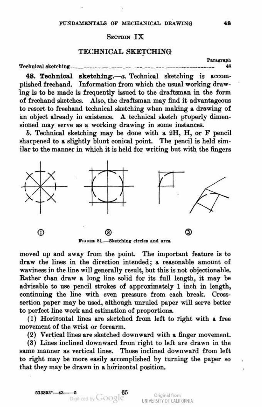
FUNDAMEI.'ITALS OF MECHANICAL DRAWING .s SECTION IX
TECHNICAL SKE'J'CHING Pa .. ~~
TecbnleAl&keteblnc-_________________________________ ______ ______ ______ ~
48. Technical sketcbing.--a. Technical sketching ill accomplished freehand. Information from ""hich the usual working draw'ing is to be made is frequently issued to the draftsman in the form of freehand sketches. Also, the draftsman may find it advantageous to resort to freehand technical sketching when making a drawing of im object already in existence. A technica1 sketch properly dimensioned may serve &8 a working drawing in 80me instances.
o. Technical sketching may be done with a 2H, H, or F pencil sharpened to a slightly blunt conical point. The pencil is held sim· ilar to the maDner in which it is held for writing but with the fingers
(j) ®
moved up and away from the point. The important feature is to draw the lines in the direction intended j a reasonable amount of waviness in the line will generally result, but this is not objectionable. Rather than draw a long line solid for its fuU length, it may be advisable to use pencil strokes of approximately 1 inch in length, continuing the line with even pressure from each break. Crosssection paper may 00 used, although unruled paper will serve better to perfect line work and estimation of proportions.
(1) Horizontal lines are sketched from left to right with a free movement of the wrist or foreann.
(2) Vertical lines are sketched downward with a finger movement. (8) Lines inclined downward from right to left are drawn in the
same manner as vertical lines. Those inelined downward from left to right may be more easily accomplished by turning the paper so that they may be drawn in a hOrizontal position.
( Or'gir 01",,", UNM~\fTY Of (AllfORNIA
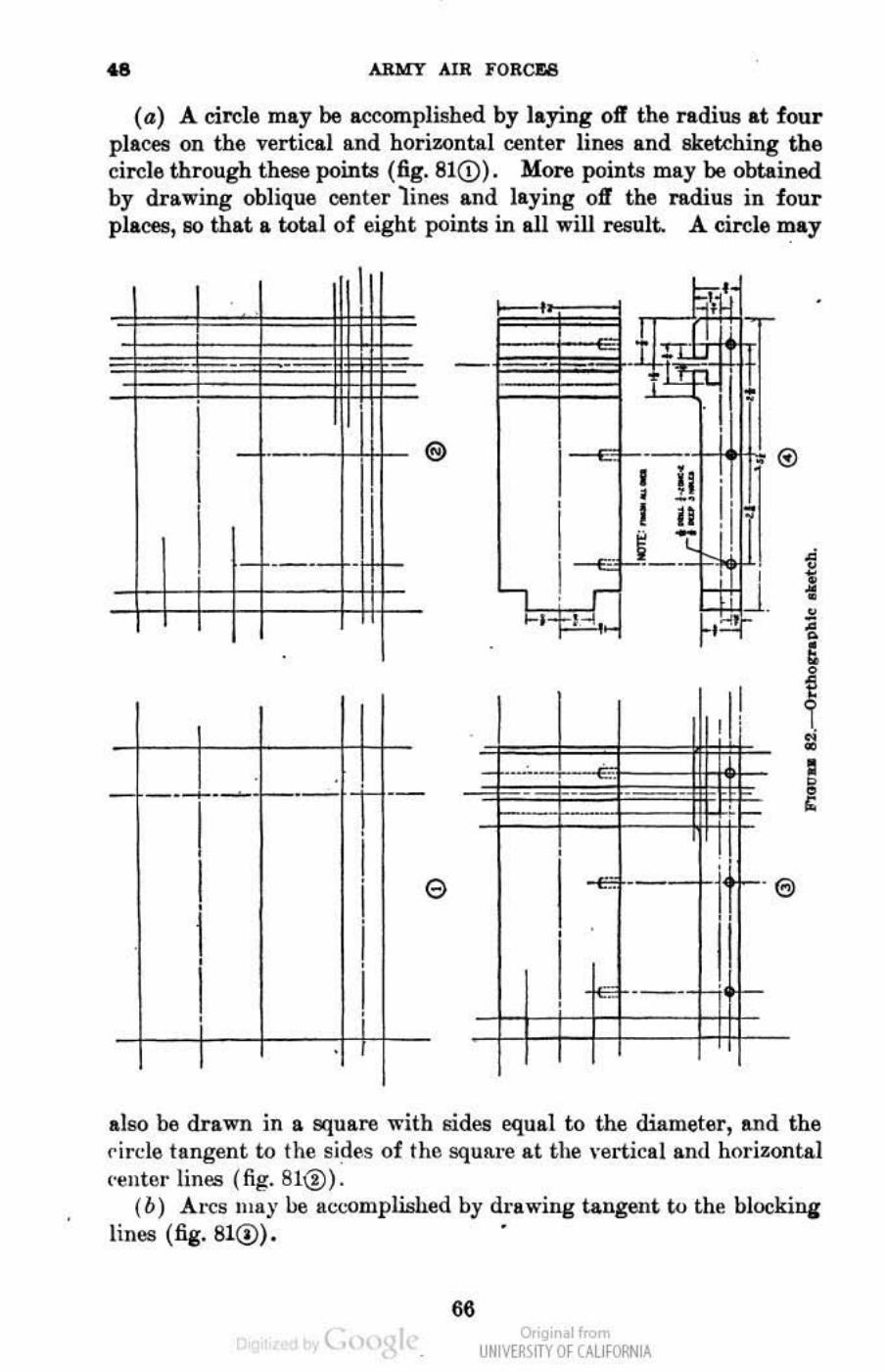
.. ARMY AIR FORCJ:8
(a) A circle may be accomplished by laying off the radius at four plaCet! on the vertical and horizontal center lines and skekhing the circle through these points (fig. 81eD). More points may be obtained by drawing oblique center lines and laying off the radius in four placell, SO that a total of eight points in all will result. A circle may
. ---' - .--+---
I I •
I , I ,
.
I
• --•
I •
I •
I •
I •
®
e
. -_.-
also be drawn in a square with sides equal to the diameter, and the circle tangent to the sides of the squfl,re at the vertical and horillontal ('enter tines (fig. 81@).
(b) An:s Illay be act'Omplhihed by drawing tangent to the hJockina lines (fig. 810). .
66 t., o,'gir . 1",,",
UNM~\fTY Of (AllfORNIA
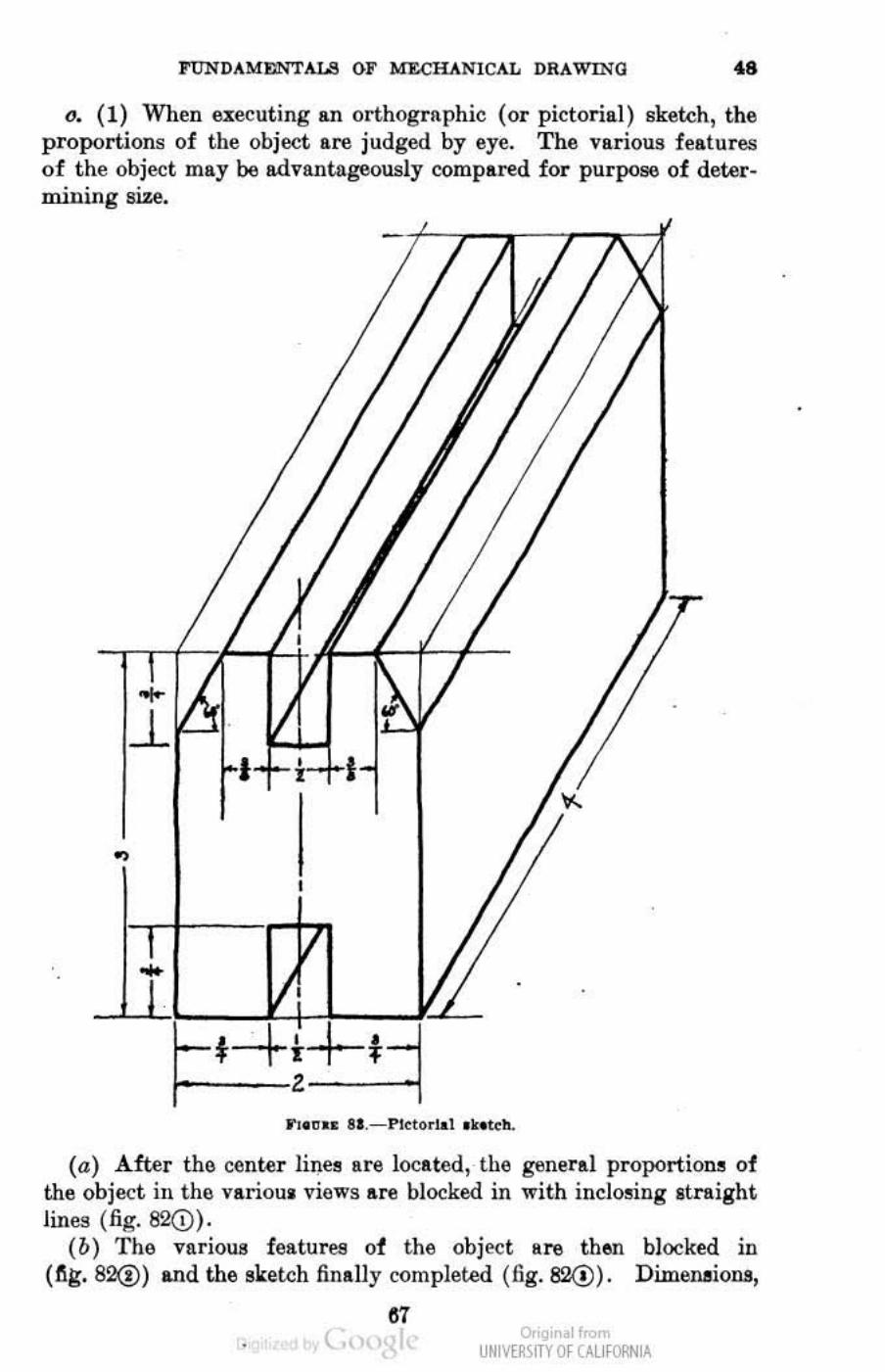
l"UNDAME.!'''TALS OF MECHANICAL DRAWING .. o. (1) When exeeuting an orthographic (or pictorial ) sketch, the
proportions of the objeet are judged by eye. The various features o f the object may be advantageously compared for purJlOS6 of determllllng !IlZe.
... ~
,
(a) After the cente r lil).ee are located, the general proportione of the object ill the varioul views !lore blocked ill with inclo~illg Itn ight lines ( fig. 82(i)).
(b) The various features of the object are th6Jl blocked in ( ~g. 82@) and the 9ketch finally completed (fig. 82<!). Dimensions,
" ( o,'gir I< UNM~\fTY Of (AllfORNIA
•
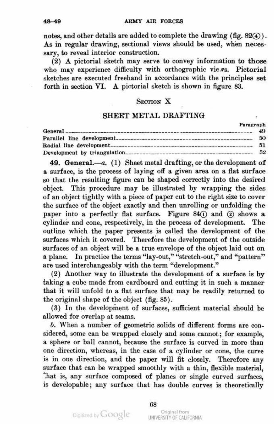
..... , ARMY AIR FORCES
notes, and other details are added to complete thll Jnwing (fig. 82G). As in regular drawing, soctional views should be used, whell necessary, to reveal interior construction.
(2) A pictorial sketch may serve to convey information to those who may experience difficulty with orthographic vie HR. Picoorial sketches are executed freehand in accordance with the principles set forth in S8(;tion VI. A pictorial sketch is shown in figure 83.
SWI'lON X
SHEET METAL DRAFTING P.'U'~l>h (k"" ... t _________ • ____ ___ _______ • __ __ ' _. __ __ ______________ ____ ___ __ ~O
Parallel Une developmenl _______ ______ _____ ____ ___ __ ____ __________ .____ M Radial line development______ _______ __________ ____ _________ _____ ____ __ _ 1I1 [)evel ""men t br I ria pguliltlon. __ __ _ __ _ _ __ _ __ _ _ __ _ _______ ____ _ ______ __ _ __ _ fi:.!
49. General.-a. (1) Sheet metal drafting, or the development of n surface, is die proc- S3 of laying off a given area on a flat surface !;O that the resulting figure can be shaped correctly into the desired objed. This procedure may he illustrated by wrapping the sides of an ohject t ightly with a piece of paper cut to the right size to cover the surface of the object exactly Ilnd then unrolling or unfolding the paper into a perfectly flat surface. Figure 84(i) and ® shows a cylinder and cone, respectively, in the process of developmenL The outline which the paper presents is called the development of the surfaces which it covered. Therefore the de,·e lopmel.lt of the outside surfaces of an object will be a true envelope of the object laid out on a plane. In practice the terms "Iay-out,'" "stretch.out," and "pattern" are used interchangeably \\jth the term "development."
(2) Another way to illustrate the development of a surface is by iaking a cube made from cardboard and cutting it in such II. manner that it will unfold to a flat surface that may be readily returned to t.he originlll shape of the object (fig. 8!i).
(3) In the development of sudaces, sufficient material should be allowed for overlap at seams.
b. 'Vhen a number of geometric solids of different forms are con_ sidered, !;ollie can be wrapped closely and some cannot; for example., a sphere or ball cllnnot, because the surface is curved in more than one direction, whereas, in the case of a cylinder or cone, the curve is in one direction, and the paper will fit closely. Therdore any surface that can be wrapped smoothly with a thin, flexible material, ~.h at is, any surface composed of planes or single curved surfaces, is dev~lopllbJe; allY surfal:e that has double curves is theoretically
t., , 68
o,'gir I< UNM~\fTY Of (AllfORNIA
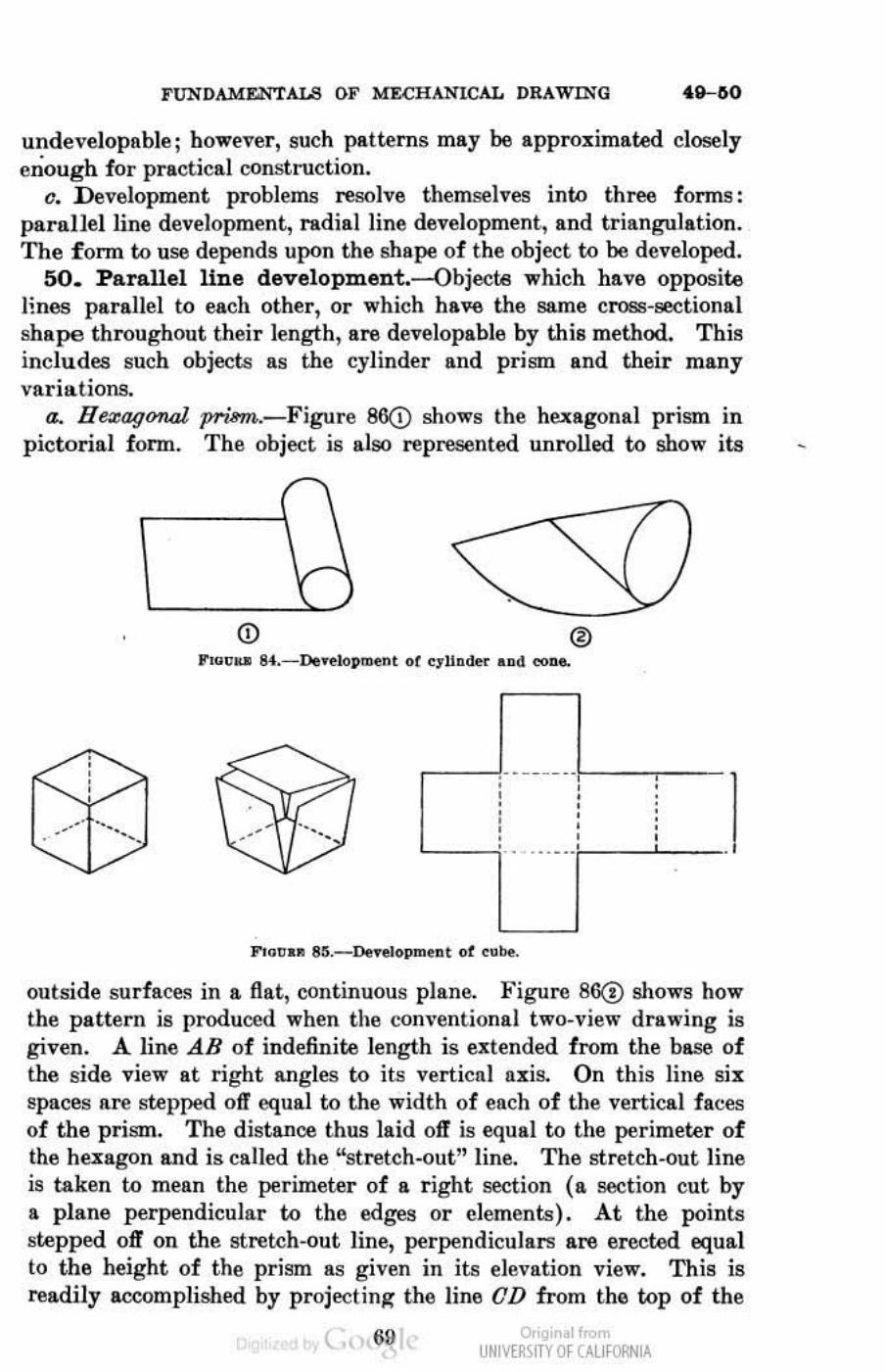
FUNDAMENTALS OF MECHANICAL DRAWING
undevelopable; however, such patterns may be approximated closely enough for practical CQnstruction.
c. Development problems resolve themselves into three forms: parallel line development, radiailine development, and triangulation. The form to use depends upon the shape of the object to be developed..
50. Parallel line development.--Objecte which have opposite lines parallel to each other, or which have the same cross-sectional shape throughout their length, are developable by this method. This includes such objects as the cylinder and prism and their many variations.
a. H~agOTUd prism..-Figure 86<D shows Ihe hexagonal prism in pictorial form. The object is also represented unrolled to show its
. -- - - - .. • • , • , • • • • • • • • • • • • • • • • • • . . .. _ .. .
.
outside surfaces in a flat, continuous plane. Figure 86(!) shows how the pattern is produced when the com'entionai two_view drawing is given. A. line AB of indefinite length is utended from the base of the side view at right angles to its vertical axis.. On this line six spaces are stepped off equal to the width of each of the vertical faces of the prism. T he distance thus laid oft" is equal to the perimeter of the huagon and is called the "stretch-out" line. The stretch-out line is taken to mean the perimeter of a right section (a sect ion cut by a plane perpendicular (;Q the edges or elements). At the points stepped. off on the stretch-out line, perpendiculars are erected equal to the height of the prism as given in its elevation view. This is readily accomplished by projecting the line OD from the top of the
o,'gir I< UNM~\fTY Of (AllfORNIA
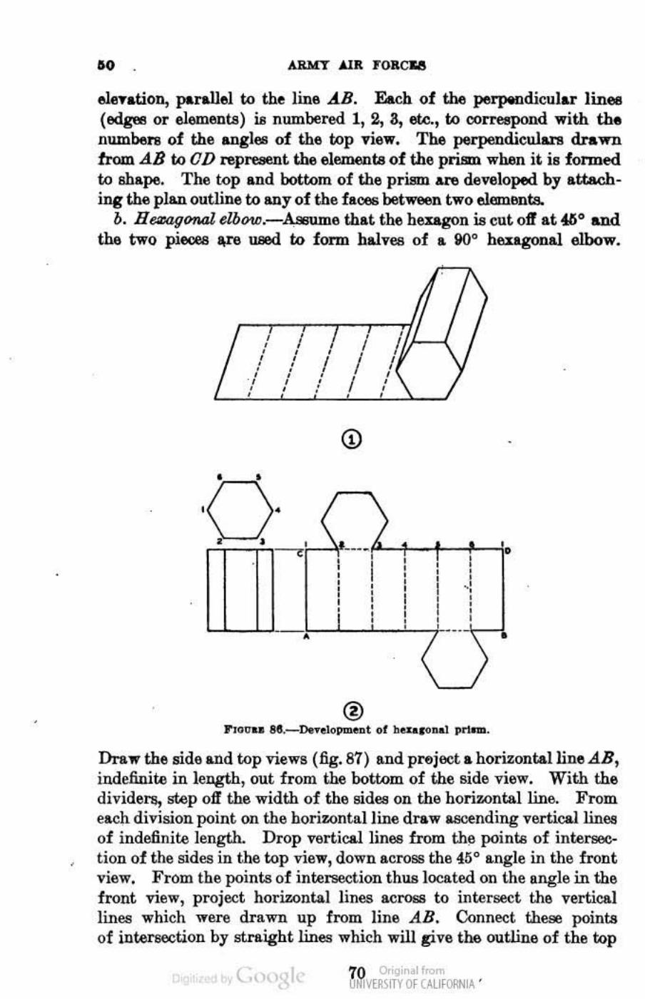
•
•
•• AlU(1' .ilK FORCU
elention, parallel to the line AB. &ch of the peifiPdicular linea (edges or elements) is numbered 1,2, a, etc., to oorTe8pOlld with the numbers of the angles of the top ",iew. The perpendiculare drawn from.dB to OD represent tbeelementeof the prism. when it. is formed to shape. The top and bottom of the prism. AnI developed by attach. ing the plan outline to any of the faces between two eJ.ar:nants.
b. H~gfYll4l dbQ1C.-Assume that th& bengon is cut oft at ffio and the two pieces t,r8 uxd to form halves of a iKlO heu.gonal elbow.
, I , , , I I , , ,
/ , , I I • • • • , , • I
, , , , , • , • , , •
(j)
• • \ , •
• , , ~ • , , •
• , • • • • • • • • • • ., • • I • I • I • • • ,
• • • • • - ,
® r,o<rU " ._o.r..lo_t 01 bOU«lnal pl'lnlo.
Draw the side and top views (fig. 87) and project a horizontal line AB, indefiuite in length, out from the bottom of the side view. With the dividers, step off !.he width of the sides on the horizontal line. From each division point on the horiwntalline draw &SCf!nding verticallinee of indefinite length. Drop vertical lines from the points of intersection of the sides in the top view, down across the 45° angle in the front view. From the points of intersection thus located on the angle in the front view, project horizontal lines across to intersect the vertical lines which ware drawn up from line AB. Conned these points of ilitersecU.Oll by straight lines which will pve the outline of the top
( 70 o,'gir I< UfIM~\fTY Of (AllfORNIA '
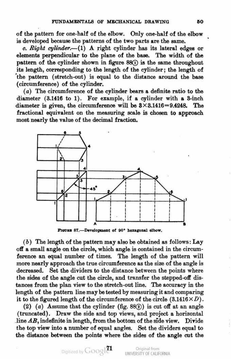
FUNDAMI'ilNTALB OF lIBCHANlCAL DRAWING 110
of the pattern for one-half of the elbow. Only one-half of the elbow is developed because the patterns of the two parts are the same.
o. Right cyUtide7'.-(I) A right cylinder has its lateral edges or elements perpendicular to the plane of the base. The width of the pattern of the cylinder shown in figure 8B(!) is the same throughout its length, conesponding to the length of the cylinder; the length of 'the pattern (stretch--out) is equal to the distance around the base (cireumf.erenoo) of the cylinder.
(a) The circumference of the cylinder bears a definiu ntio to the diameter (3.1416 to 1). For example, if a cylinder with a a·inch diameter is given, the circumference will be 8x8.1416-9.4248. The fractional equivalent on the measuring ecale i.e r.hcsw to approach most nearly the value of the decimal fraction.
: , ,
(0) The length of the pattern may al90 be obtained as follows: Lay off a emall angle on the circle, which angle is contained in the circumference an equal number of times. The length of the pattern will more ne&rly approach the true circumference as the trim of the angle is deeree.sed. Set the dividers to the distance between the points where the trides of the angle cut the circle, and transfer the stepped--ojf distances from the plan view to the etl'ekh-ont line. The accuracy in the length of the pattern line may be tested by measuring it and comparing it to the figured length of the circumference of the circle (8.1416 x D).
(2) (a) Assume that the cylinder (fig. 88C!) is cut off at an angle (truncated). Draw the side and top views, and project a horizontal
.line AB, indefinite in length, from the bottom of the side view. Di ... ide t.be top view into a number of equal angles. Set the dividers equal to the distance between the points ",here the sides of the angle cut the
( 71 o,'gir I< UNM~\fTY Of (AllfORNIA
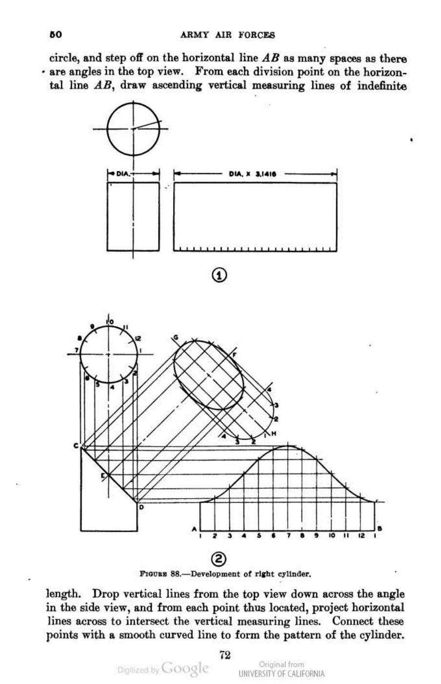
.0 ARMY AlR )'ORCI'.8
circle, and step off on the horizontal line AB as many BpaCl'.!! 11.8 there • are angles in the top view. From each division point. on the horizon
tal line AR, draw a_Ddin&" vertical measur ing lines of indefinite
" '\
\ / 1-_1 I' DIA.' *",., • ' I . .
,
® """n .. 88,- Oe'reloPldeat of rl&'hl OJ'1!n"' • .
length. Drop vertical linea from the top view down across the angle in the side view, and from each point thus located, project horizontal lines across to intersect the vertical mellSUring lines. Connect these pointa with a smooth curved line to form the pattern of the cylinder.
72 ( Or'gil I<
UNM~\fTY Of (AllfORNIA
,
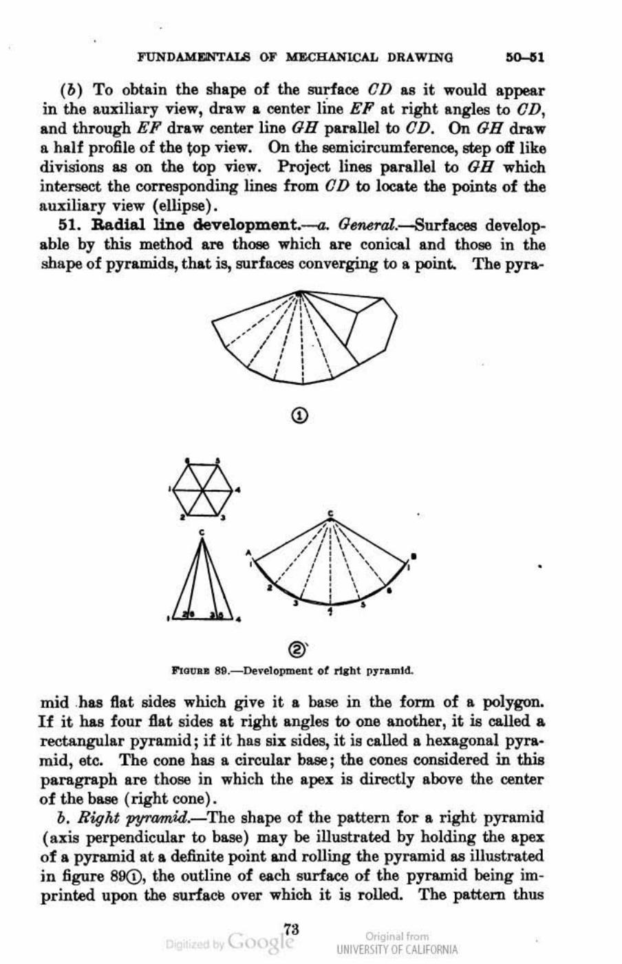
I"UNDAMI'iiNTALS OF MZCIL\NlCAL DRAWING
(b) To obtain the shape of the 8U~aoe OD as it would appear in the auxiliary view, draw a oenter liM EP at r ight angles to OD, a nd through EP draw center line OB parallel to OD. On OB draw a half profi le of the toP view. On the semicircumferenoe, Btep off like divisions as on the top view. Project lines parallel to OR which intersect the corresponding lines from OD to locate the points of the auxiliary view (ellipse).
51. Radial line deve10pment.-a. O~.-Surfacea developable by this method &nI thOllll which are conical and those in the shape of pyramids, that is, surfaces converging to III. point. The pyra-
,
<
.~il\\ ~:::::;:::7\ /" 1/ " . " " ' I " -- J' _ \ , ' , , : \ , ,
• <
'1'\':'\ ' " /i'l'\ , '\, .. , ' \ "'-.. ,' I , , , , , , • ,
•
@'
• •
mid ,haa Hat sides which give it a base in the fonn of a polygon, If it has four Hat sides at right angles to one another, it is called a rectangular pyramid; if it has six sides, it is caUed a hexagonal pyramid, etc. The cone hllEl a circular base; the cones considend in this paragraph are thOll6 in which the apex is directly above the center of the b&ee (right cone).
b. Right pyramid.-The shape of the pattern for a right pyramid (a]tis perpendicular to base) may be illustrated by holding the apex of a pyramid at a definite point and rolling the pyramid 118 illustrated in figure 89G), the outline of each surface of the pyramid being imprinted upon the surface over which it is rolled. The pattern thus
( 73 o,'gir I<
UNM~\fTY Of (AllfORNIA

•
" ARMY AIR FOR(%.!II
• obtained converges to • point, and all the elements are equal in length. Figuro 89(!) illust.rateS the ndial line method of developing such a pattern. The two views provide the nec-pary shape deacription and dimenl:lions. All edges are numbered collespondingly in both views. The spa: of the pyramid is taken at oenter 0, and an are.dB is drawn, indefinite in length, with the length of an outside edge of the pyramid as .. radius. Although all the edgell are equa.l, they do not appear 80 in elevation becallll6 of the inclined SIlrfa<:es. Thus only the outside edges sbow the true lengths for use as the radius of the are. A point is selected on the arc for the first. element. With the dividers set to a distance equal to the length of a side of the base, the other elements are stepped oiy around the arc. l'he points located in this manner are then connected with strnight lines to form the outline of the pattern. Lines are drawn from these points to the center point to show clearly where the folds will be made when the object. is brought to shape.
•
•
c. Right cone.-The pattern of the right. cone (fig. 90) is a portion of -a circle, the radius of which is equal to the slanting height of the cone. One edge of the patwrn must. be equal to the distance around the iJase of the cone; tharefore this distance is laid off on the circumference of the pattern circle. To do this the approximation method, as described in paragraph 00c(1) (b), is used. The end points of the distance laid off with the oenter of the circle are connected, and the pattern is complete. Should it be desired to cut. a portion of the cone away on a line parallel with the base, the slanting height. of the small cone thus formed is taken as a radius and an arc swung on the pattern using the original oenter point. When the pattern is cut ont, the two straight. sides are brought together to form the cone.
(l) The 8urfaoo development of a truncated pyramid (fig. 9l) is similar to that for the whole pyramid, with the exception that now the elements are no longer the same length. A two-view drawing is
( o,'gir I< UNM~\fTY Of (AllfORNIA
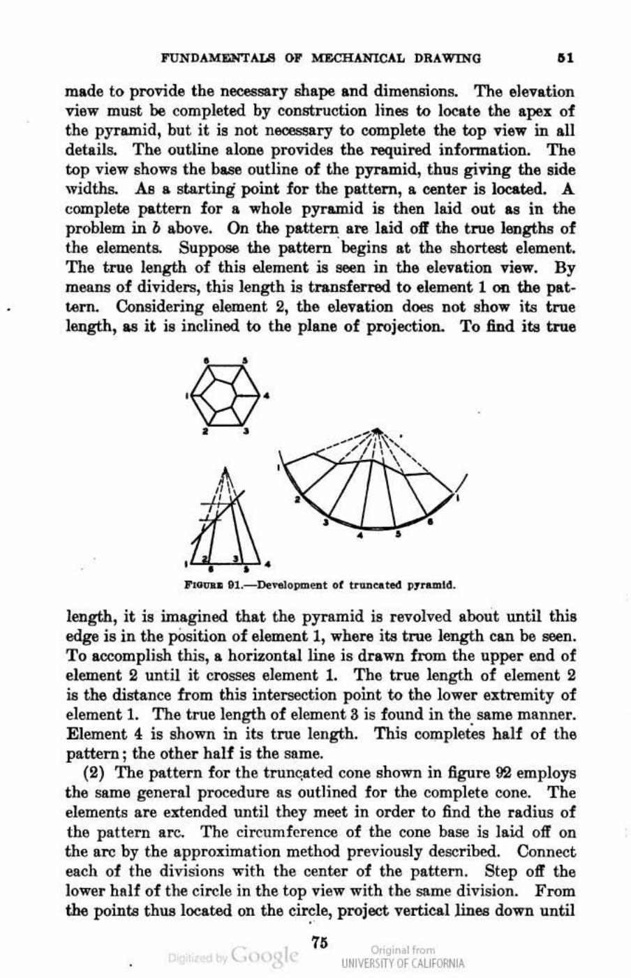
FUNDAM&li'TAL8 OF M'IlCHANICAL DRAWING " made to provide the necessary shipe and dimel18ions. The elevation view must be completed by construction lines to locate the IpeX of the pyramid, but it is not neol!i!ary to ooroplete the top view in all details. The outline alone pro-ridee the required infonnation. The top view shows the b.se outline of the pyramid, thus giving the aide widths. As a starting point for the pattern, a center ia 1000ted. A complete pattern for a whole pyramid is then laid out as in the problem in b above. On the pattern are laid oft the tMle lengths of the element!!. Suppose the pattern begins at the shortl!6t element. The true length of this element is seen in the elevation view. By means of dividers, this length is transferred to element 1 on the pattern. Considering element 2, the elevation does not show it.<! true length, as it is inclined to the plane of projection. To find its true
,
. ---'~. / ,
,
length, it is imagined that the pyramid is revolved about until this edge is in the pOsition of element 1, where its tnIe length can be IJ6en. To accomplish this, a horizontal line is drawn from the upper end of element 2 until it crosses element 1. The true length of element 2 is the distance from this intersection point to the lower eJ:tremity of element 1. The true length of element 3 is found in the same mRnner. Element 4 is shown in its true length. This completes half of the pattern ; the other half is the same.
(2) The pattern for the trun~ated cone shown in figure 92 employs the same general procedure as outlined for the complete oone. The elements are extended until they meet in order to find the radius of the pattern are. The circumference of the cone base is laid oft' on the Ste by the apPI"OJ:imation methoo previously described. Connect each of the divisions "With the center of the pattem. Step olt" the lower half of the circle in the top view with the same division. From the points thllillocated on the e~le, project verticallioes down until
( Or'gir I< UNM~\fTY Of (AllfORNIA
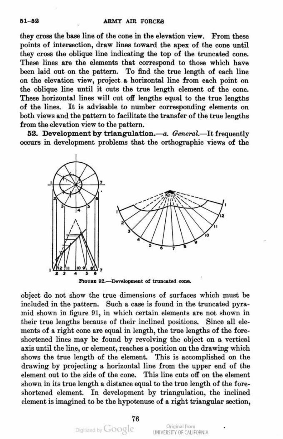
111- 11::1 ARMY AlR FORCES
they cross the base line of the cone in the elevation view. From these points of intersection, draw lines toward the ape!: of the cone until they cross the oblique line indicating the top of the truncated cone. These lines are the elements that ooIlespond to those which have been laid out on the pattern. To find the true length of each line on the elevation view, projeeta horizontal line from each point on the oblique line until it cuts the true length element of the cone. These horiwntal lines will cut olf lengths equal to the true lengths of the lines. It is advisable to number ooilEEIponding elements on both views and the pattern to facilitate the transfer of the true lengths from the elevation view to the pattern.
52. Development by trlangulation.-a. Oen.eral.-It fI'llquently occurs in development problems that the orthographic views of the
,
object do not show the true dimensions of surfaces which must be included in the pattern. Such a case is found in the truncated pyramid shown in 6gure 91, in which certain elements are not shown in their true lengths because of their inclined positions. Since all elements of a right cone are equal in length, the true lengths of the foreshortened lines may be found by revolving the object on a vertical axis until the line, or element, reaches a position on the drawing which shows the true length of the element. This is accomplished on the drawing by projecting a hori:r:ontal line from the upper end of the element out to the side of the cone. This line cuts off on the element shown in its true length a distance equal to the true length of the foreshortened element. In development by triangulation, the inclined element is imagined to be the hypotelluse of a right triangular section,
76 ( Or'gir I.
UNM~\fTY Of (AllfORNIA
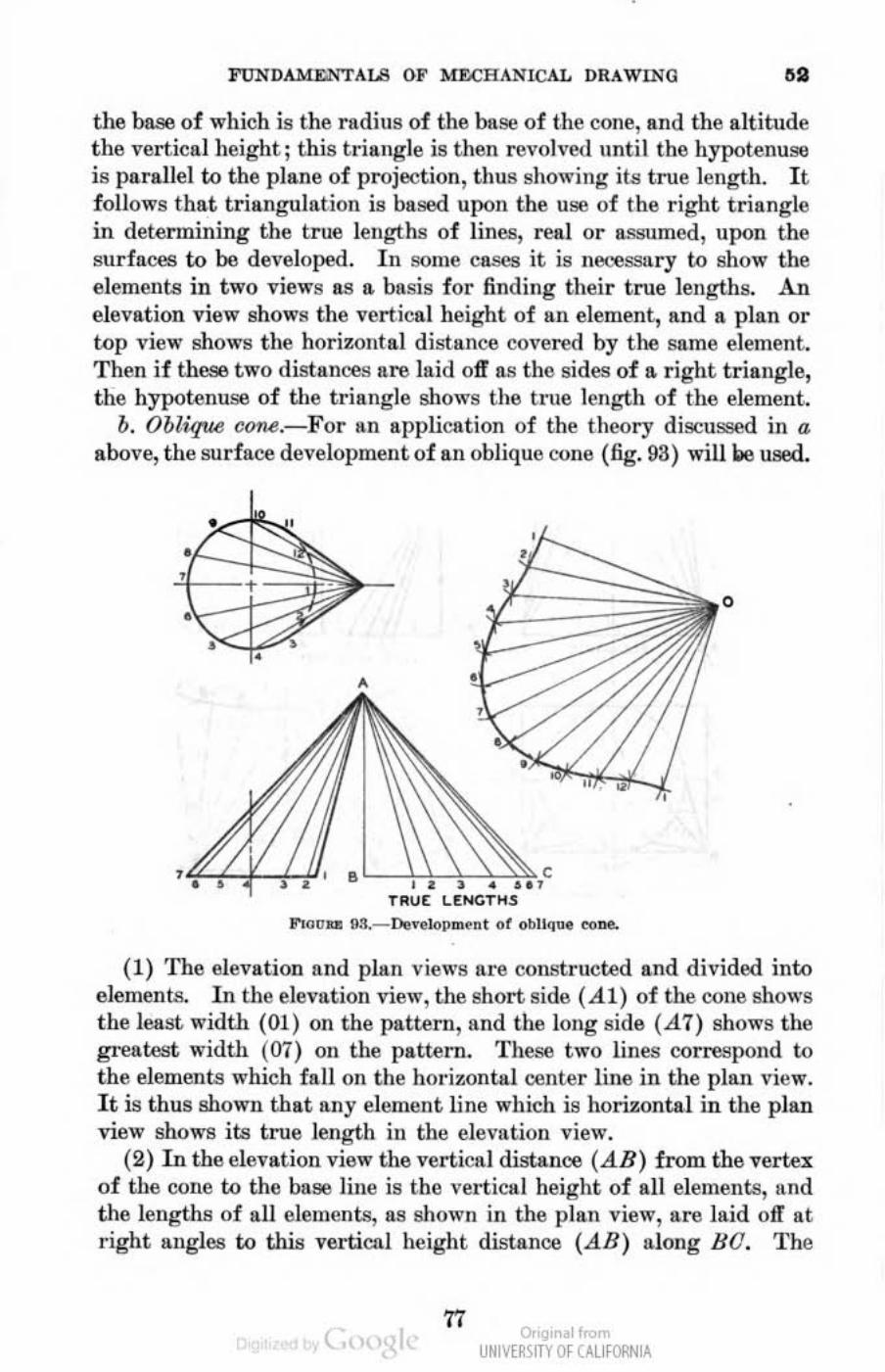
FtlN DAMr.lI.'TAUI OF MECH ANICAL DRAWING ,. the base of which is thc radius of the base of thc conc, and thc alt itude the vertical height; this t riangle is then rovolnld unt il the hypotenuge is parallel to the plane of projection, tll US showing its true length. It follows that triangulat ion is based upon thc use of the r ight t riangle in determining the true lengths of linCli, rcal or a.ssumed, upon the surfaces to be developed. I n some cases it is netoessu ry to show the elements in two views as I\. bas.is for finding their true lengths. An elevation view shows thc vertical hcight of 11I1 clement, find a plan or top view shows tIle horizontal distance covered by the samc element. Thtm if thess t wo distances are laid off as the side!! of a. r ight triangle, the hypotenuse of !lIe trianglc shows the true length of the element ..
b. Oblique cOM.-For an application of the theory discussed in a above, the surface devclopment of an oblique cone (6g. 93) will w used.
, TRUE
lI'!<lO.., D3._De~.Jopm~nl ot Obllq", ... DIJ.
(1) The elevlltion and plan views are constructed and divided into elements. I n the elevation view, the short side ( A I ) of the cone shows t he least width (01) on thc pattenl, Ilnd thc long side (..47) shows the greatest wid!ll (07) 011 the pattern. These two lines correspond to the elements which fall on the horizontal center line in the plan vicw. I t is thus shown that any element linc which is horizontal in the plan view shows its true length ill the elcvation vicw.
(2) In the elevat ion view thc vertical distance (AB) from thc vertex of tlle COlle to the base Iille is thc vel1icIII heigllt of all elements, and the lengths of all elemcnts, as ahown in the plan view, are laid off at righ.t tlngles to this vertiCllI height distance (.dB) along BO. The
17 O. II<...
UNIVERSITY Of CALI fORNIA ,,<
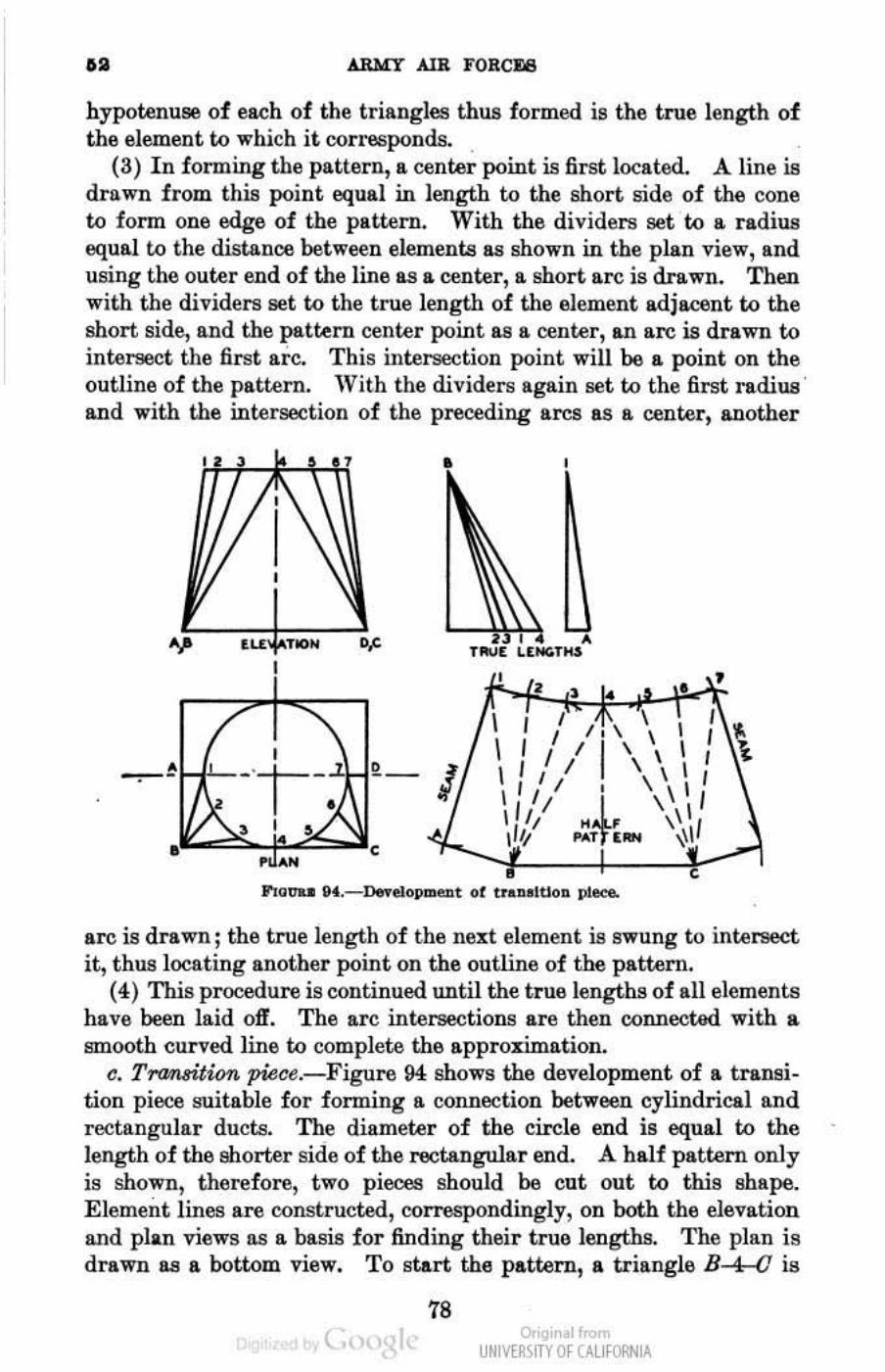
.. ARLIT AlR FORCJ'.J8
hypotenuse of each of the triangles thus formed is the true length of the element to which it. corresponds.
(3) In forming the pattern, Ii center point is first located. A line is drawn from this point equal in length to the short side of the cone to form one edge of the pattern. With the dividers set to Ii radius equal to the distance between elements as shown in the plan view, and using the outer end of the line as Ii center, a short are is drawn. Then with the dividers set to the true length of the element adjawnt to the short side, and the pattern center point Ill! Ii center, an are is drawn to intersect the fi rst arc. This llltersection point will be Ii point on the outline of the pattern. With the dividers again set to the first radius ' and with the intersection of the preceding ares as a center, another
. ~ ,., , , • T ..... [ LUfC.TIU , , , I • I , I , i , -,-, ,- J. \ I " I
\ " , \ \ \ I
\ , f I \ \ \ I III "*, ""'T , ... ", ,
arc is drawn; the true length of the next element is swung to intersect it, thus locating another point on the outline of the pattern.
(4) This procedure is continued until the true lengths of all elements have been laid off. The arc intersections are then connootOO. with a smooth curved line to complete the approximation.
c. Transition piece.-Figure 94 shows the development of a transition piece suitable for forming a connection between cylindrical and rectangular ducts. The diameter of the circle end is equal to the length of the shorter side of the ~tangular end. A half pattern only is shown, therefore, two pieces should be cut out to this shape. Element lines are constructed, conespondingly, on both the elevation 8.Jld plan views a.s a basis for finding their true lengths. The plan is drawn lUI a bottom view. To start the pattern, a triangle B-4-(] is
78 ( o,'gir I<
UNM~\fTY Of (AllfORNIA
laid out the same as the triangle in the elevation view which bounds the 8at part of the surface. Note that this 8at lIUrlace is paraUel to the plane of projection in the elevation view and therefore its tnl6
shape is shown. The distances betwe -n elements 1, 2, and 3, etc. in the pattern are the same as the distances between them in the plan. These distances should be laid off one at a time by drawing lUI arc each time. The true lengths of numbers 1, 2, and S are swung from B to intersect the smaller a1'(1 Numbers IS, 6; and 7 are likewise swung from O. The pattern should be stt.rted from the center and developed out each way to the sides. When point 7 is located. on the pattern, the divider!! are set to the true length of 7D, which is shown in the elevation, and with point 7 on the pattern as a center, ~ arc is swung. Then with OD on the plan as a radius, and 0 on the pattern as a center, another arc is swung to interge~t the first, thuB locating D on the pattern. Point A is located in a similar manner, thus completing the
outline of the half pattern.
Sumo:N"XI
REPRESENTATIVE WORKING DRAWINGS
--",2mhl,. and detail drawlnp",, __ ," __ ", ___ ,,,, ___ ,_,, ___ .,,_ M
63. '·.embly and detail drawiDga.-Drawings are divided, generally, into two classifications: asumbly drawings and detail drawin ...
a. (1) An-mbly drawiJ:?8S show all parts of an object in their proper position and relation to ODe another. Only principal dimensions dealing with anmbly and installation are given. Invisible outliDe is omitted unless required for clarity. Figure 95 showa an assembly drawing of a vise.
(2) Subassembly drawings are drawings which Bhow several details assembled in their working order, but are only a part of the main assembly. An 6J:ampJe of such a drawing is the screw aS9ilmbly (fig. 00), which in itself is a working unit requiring assembly with other units to make a complete assembly of the vise. Subassemblies are frequently shown in section to indicats more clearly the nllation of the various details in the assembly. Subassembly drawings have a part number, which is the number applied to that particular combination of details. Subassemblies have the details designated with their proper part numbers.
(8) Frequently, if the object involves no complicated details, an assembly drawing may suffioe to prelJ6nt complete information and may thus be used &6 a working drawina.
" ( Or'gir II< UNM~\fTY Of (AllfORNIA

" ARMY AlR FORCE6
b. A detni l dmwing carries tile millutest detail pertulfimg W the construction of ench component IJ8rt of tlle assembly. The detail drawing includes specifications of materials, dimensions, shOI) notes, changes, part numbers, flnish, number of pieces required, and other
..... "" -,
infonnatioll relative to the const ruction of the object, thus affording II. complete I)icture of the p"rt. Detnil drll.wings of the component parts of the vise, such liS the imse, swivel jaw, guide, jaw, retai ning screw, screw, hundle, nnd colin I' >l I'1) shown in fi!,'U "es 97 to lQ.i , inch.·
80
~ " UNIVERSITY Of CALI fORNIA
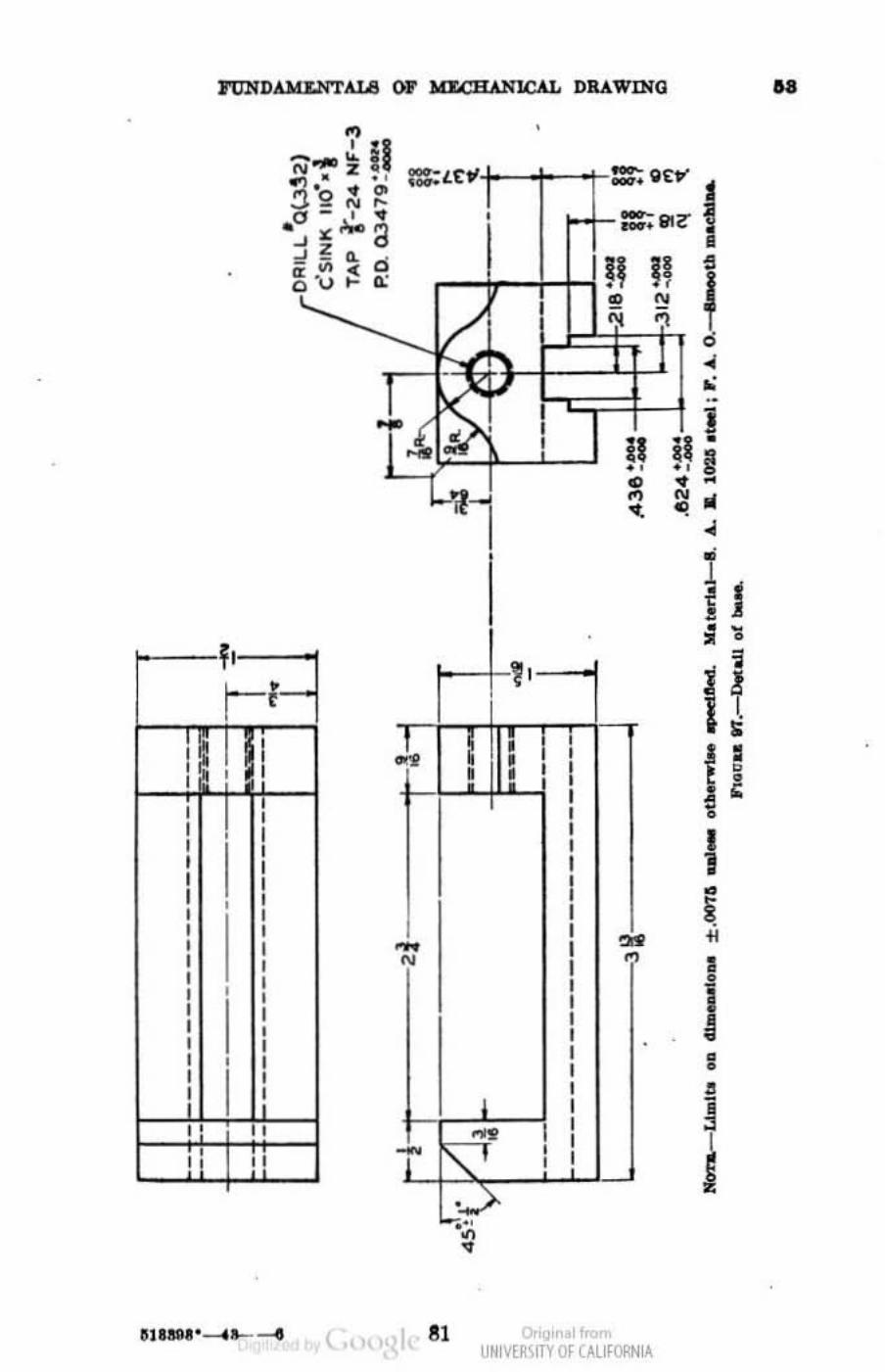
, , , , I , , , I
I I I , , , , , ,
I , , , , , , , , I , , , , , , , , , , ' , "
M --.:. n I'IIMZ • • '!l,O " ~ 0-", ... ,,- , " . '''a "z " - • d - . ~ ·U~o.:
_-+_;-::.:. Qttr' ~
, O+-:;81G" 1
'ill ,
.
• M ,.
• • .,
j ' I . !, i! • • ~ .. • • 1 l , • • 1 • •
~'I .!. T1n , t!
• •
-N
r- I
T~ ,., • ,
, , , , I , , , I , , I I I I , I I , I , , ,
I , I , I ,
81 c. nol"'-
.,. "
U~IV[~IfTV Of UUfORN lA
I , • ~
• I 1 • ~ • , , i ~ • • , • ~ I
i
..
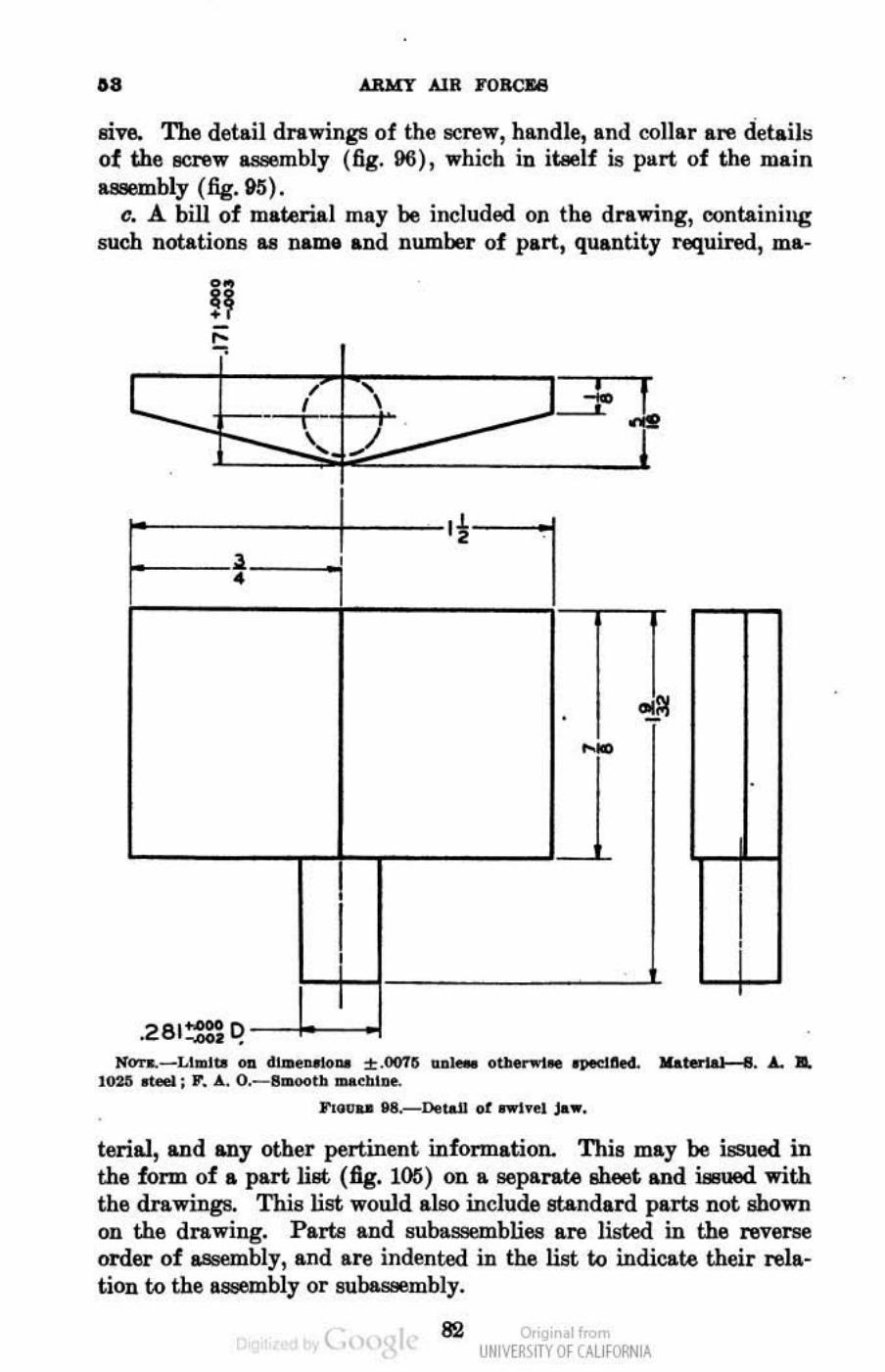
.. ARvy AIR FORCE
sive. The detail drawings of the screw, handle, and oollar are detail~ of the acrew a.ssembly (fig. 96) , which in itaelf is ptlrt of the main n;unbly (fig. 91S).
c. A bill of material may be included on the drawing, containing such notations I.B name and number of part, quantity required, ma-
~
, , , J. I
, .. -'-~ .
'i • 'I • --
., • --
I i I
.2e l~~ Joran.- LI"'IW oa .u.._ .. %.(1075 u_ otb " .t. opedllN.. Materia" I .....
l02G rteeI ; P. A.. O.- I_tl .... .,1_ nG~" N.-Detall of rwlyol ~ ...
!erial, and any otber pertinent information. This may be issued in the form of a part Iiflt (fig. 1(6) on a aeparr.te sheet and iBuued with the drawings. This list would also include standard parts not shown on the drawing. Parlil and sub&saemblies are listed in the reverse order of IBsrmbly, and are indented in the list to indicate their relation to the a __ Fmbly or subaseembly.
( 82 o,'gir I< UNM~\fTY Of (AllfORNIA
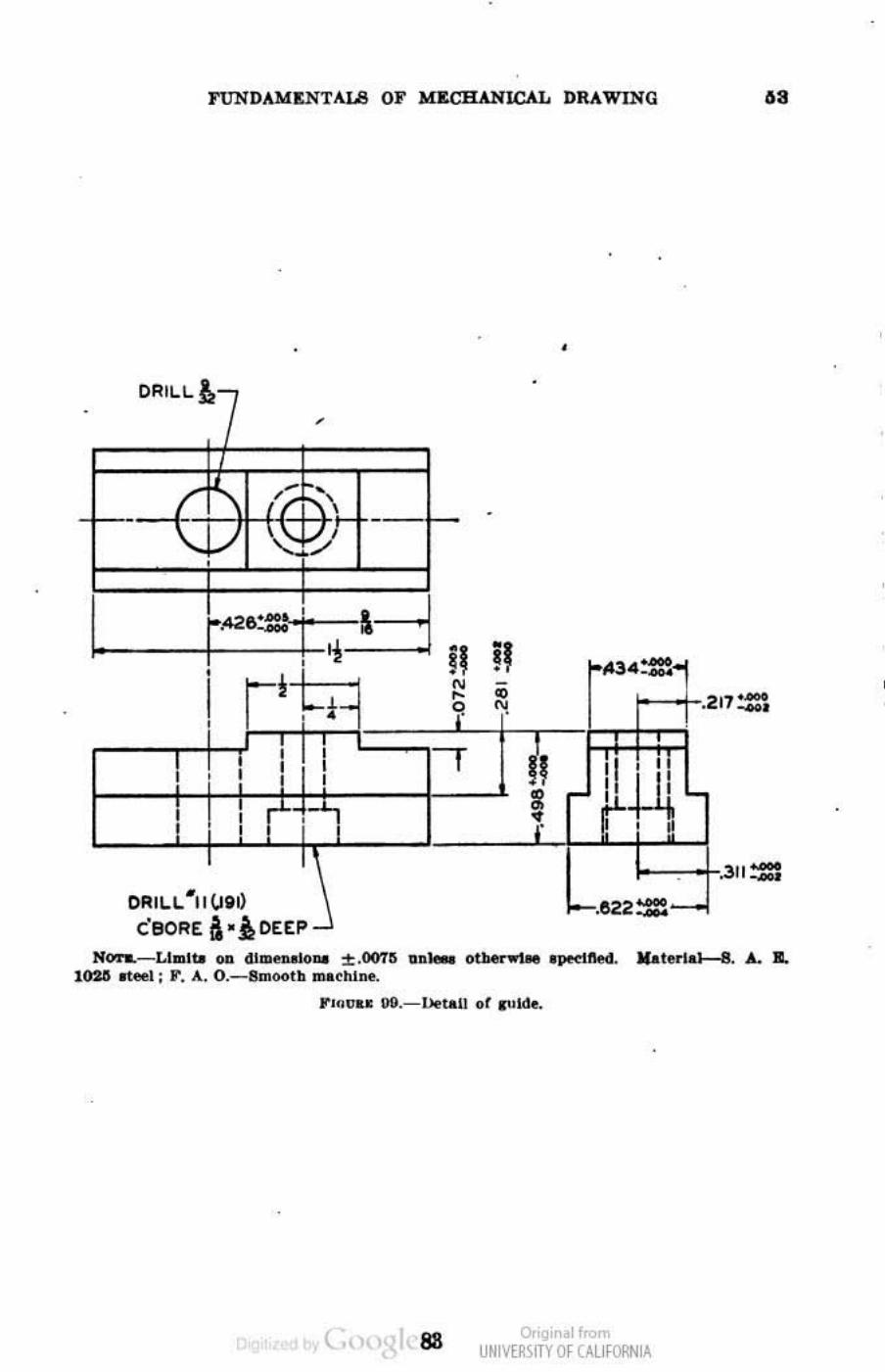
FUNDAloIENTAL8 OF loI&ClUNJCAL DRAWING
•
--I-
I. il • 1f34:= • r!~
• •
I • -• • q , ..! •
, : : -. , :I til ' , , • , , , 8 ' ' , ,
• r ~i ~ , , +---'-L",::: .
ORIL.L. '"II \.loll • .-• caORE a '»OEEP
.• ,
•
..
,._ .
311::
N'Oi~LI .. lI. on dl~ ... ~ .oon .... _ ou.e ... .,. •• pedllecl. "'lerlel---8. " IL 10211 _L: F. A. O._ 8m<H>lh "' •• hi ....
F'GIIt" 9II.-l~"1! of ."Id •.
( as o,'gi,ol",,", UNM~\fTY Of (AllfORNIA
•
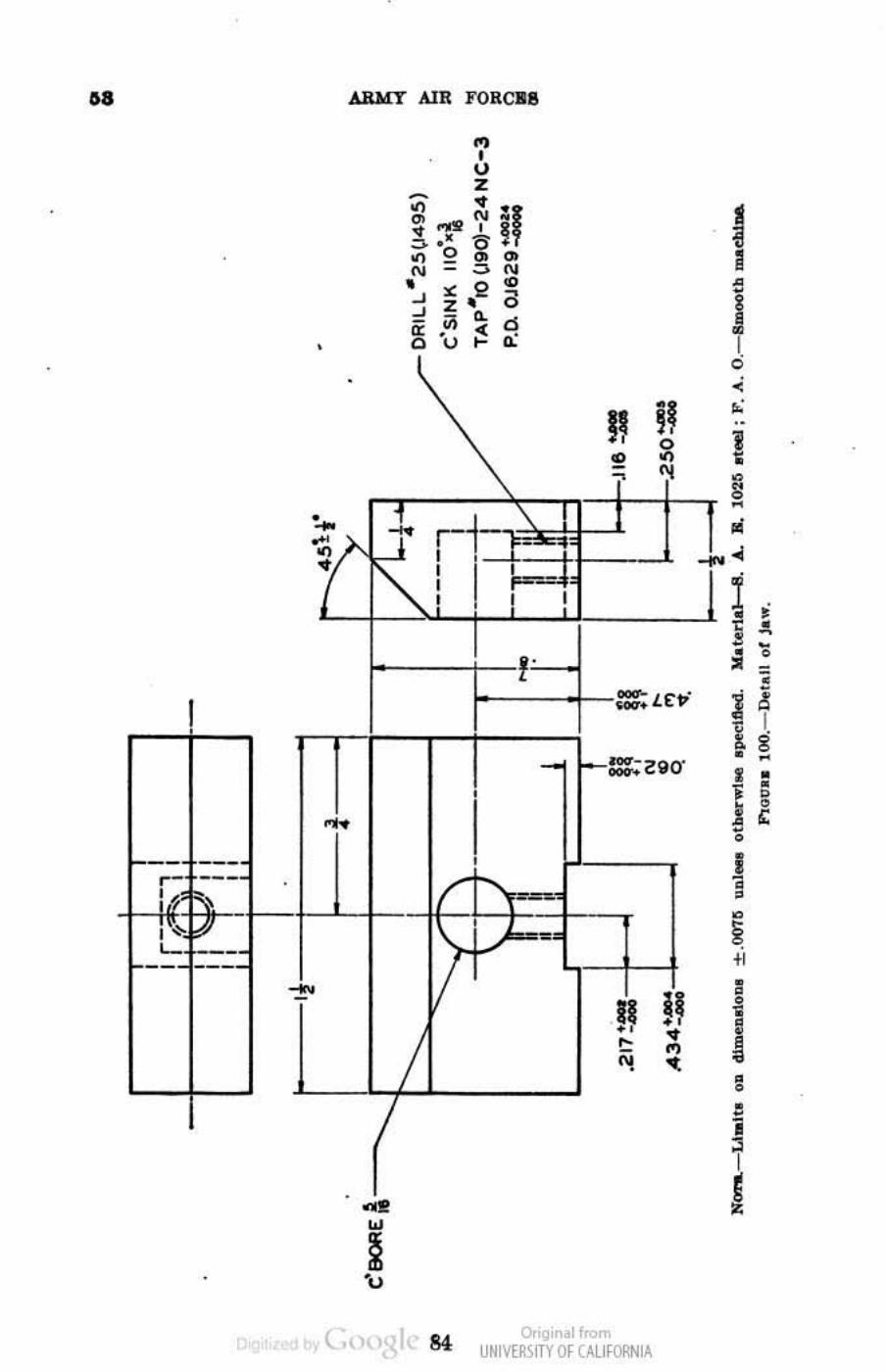
..
I
---
•
•
-
(
•• w
~ "u
i',·-+ ,
II ~ • • , ,
I • I • I J < • I • 0 • • ,;
-' '-+-L-l. _---' I ~ ,
..
~---+-:::: L£"·
I
o,'gir . 1",,", UNM~\fTY Of (AllfORNIA
• • l i • • , I -0
I , , 0
~ • , I , ~ , , i , !
, • --0
-, • I g -• • 0 0 ,
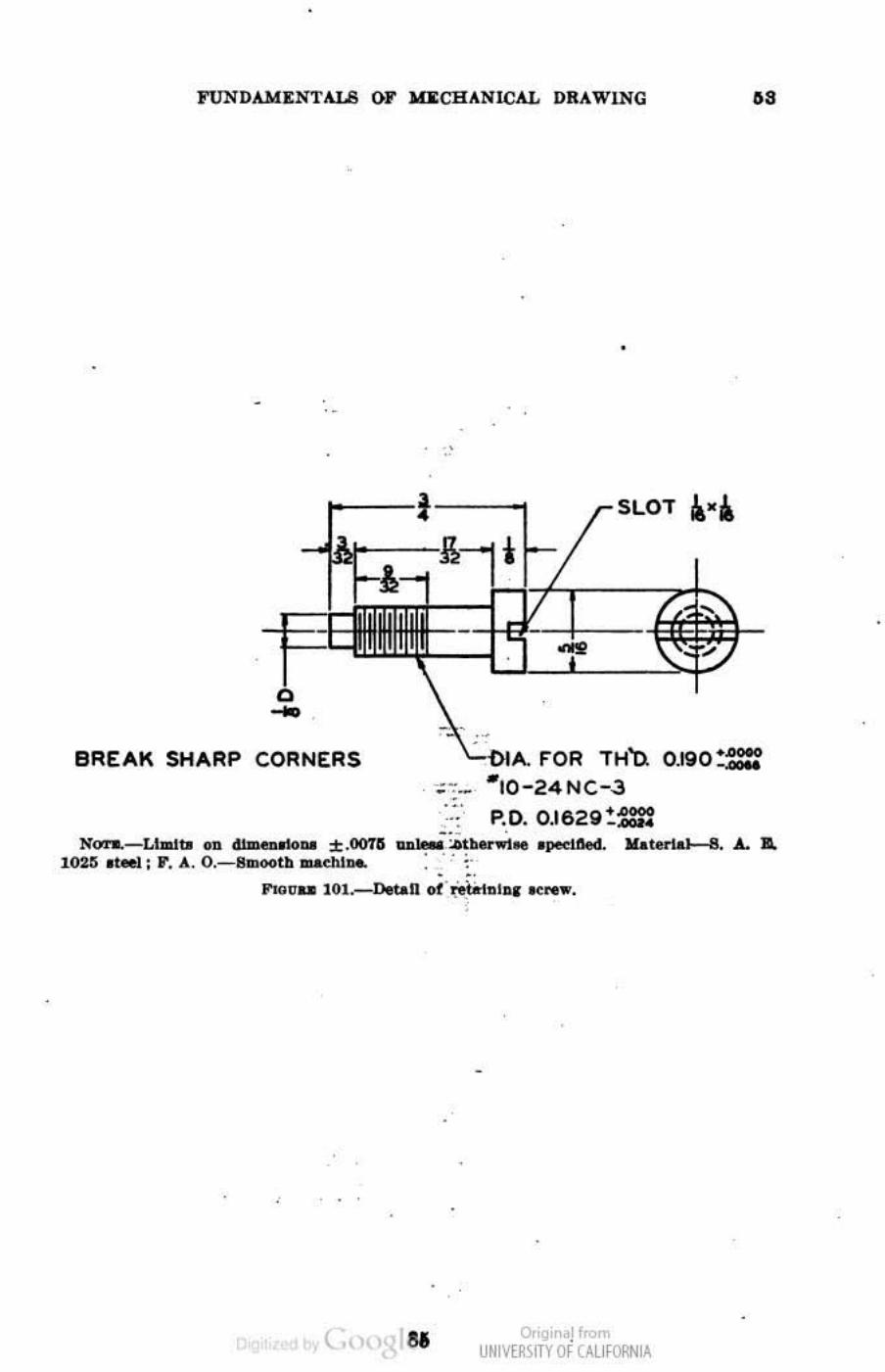
FUND.U.n:NTAU! ()F loIlI:CBANICAL DRAWING ..
•
•
BREAK SHARP CORNERS
. -
•
•
FOR TH'o. 0.190 := 10-, NC-,J
p.o. 0.1629:= "' ...... - Lhlllbl .... dlm
... 010111 ::1: .00'1'11 .. ,,' ~~b.....i .. . pe<1W. Kooterial-6 . .l.. .. l02~ 01_: F . A. O.-B1IIOC>tb ILI&CIII_ •.
• • ""'UD 101.-Deu.n ot '~"IDI .. nw.
. .
( .. o,'gir '!"""' UNM~\fTY Of (AllfORNIA
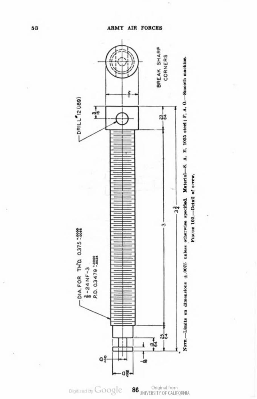
" AalofT AIR rORCIE6
• • ." 1 %0
"" Z • " •• I ' 0 " U • • -• J
J • " ••
i --• -" < j
! , - , ~ -• ~ j
! ! I. • ..
~ • -
II ,
• " • • £ • • , • a j
• II • d
" -" " • ~ • -" • ,
z a • • • • • ~ , , i • • , i , I g '-
86 c... noll«-UNIVE~SlTY Of CALIfORNIA
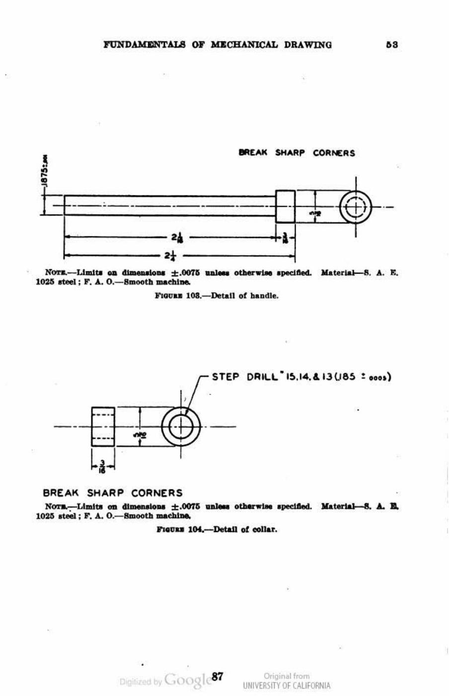
..
I
h +- - - - ~) f-- - - - -'. I I 'r
1f ...... _ l..Ia1 ..... "'."ti 7Z • :t:.lI01'li .. I __ .PKlIled. .lUte".' II. A. Ill. 1\l31i ..- : r. A.. O.-S .. ootll _<'111_
l"Iauu 10l._n.~1I of hllDllle.
---- - -+--
BREAK SHARP CORNERS Kon.-LIaItII ... "'_ 57 ',,". ± .001G n'; otMnotaoo "p""':1 MaW'" I . ....
10ZO rue.; r , " O.-lJIDootII =gbl •
-
.. ,,", .. llK.-DetaiI of .-l ....
( 87 o,'gir . 1",,", UNM~\fTY Of (AllfORNIA
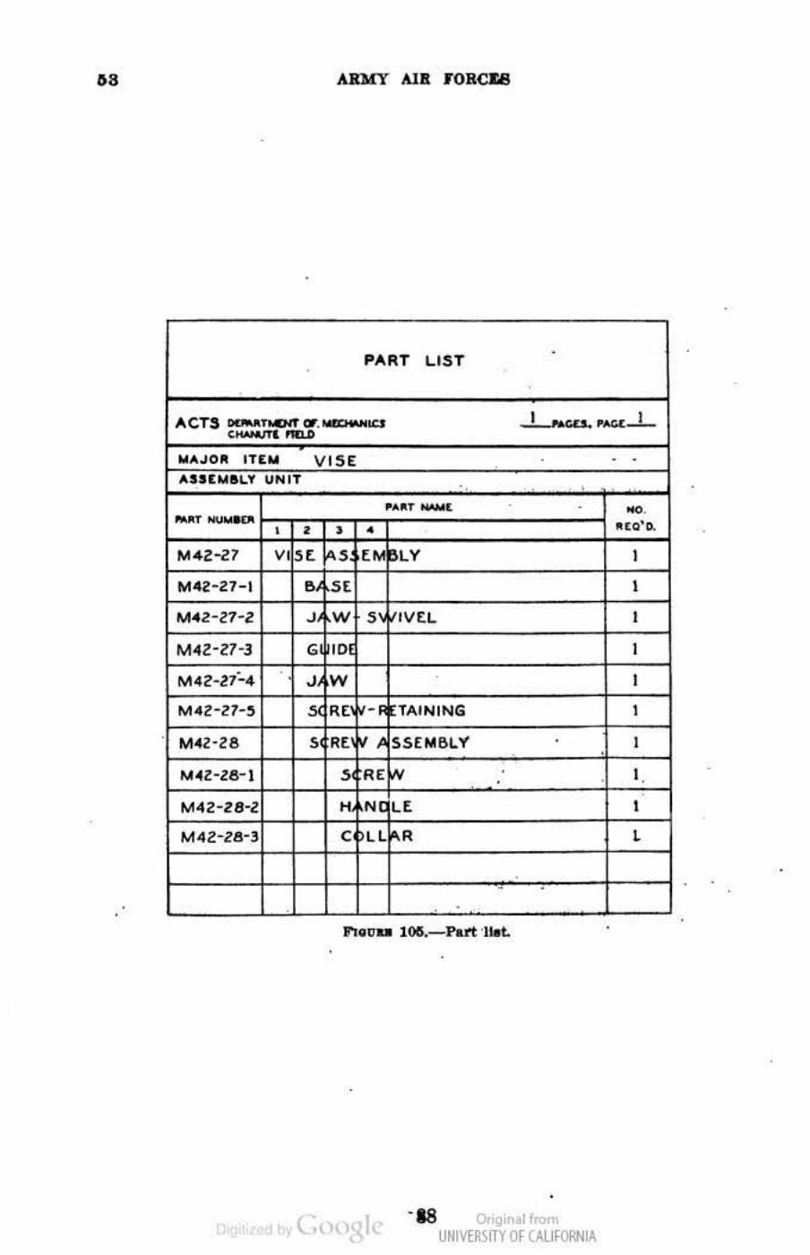
.. ARMY Ala J"ORCU
•
. PART LIST
TO . ....L.......-.. ,,-,"..1-
~ • ... - . ~ .
0.0'0-
M4Z-27 , "'42-27-1 ,
, M4Z-Z7-3 , M.N". '1W ,
, M~'28 . ~"'."< . ,
. , . . , c ,
.
.
t., -18 o,'gir ol",,", UNM~\fTY Of (AllfORNIA
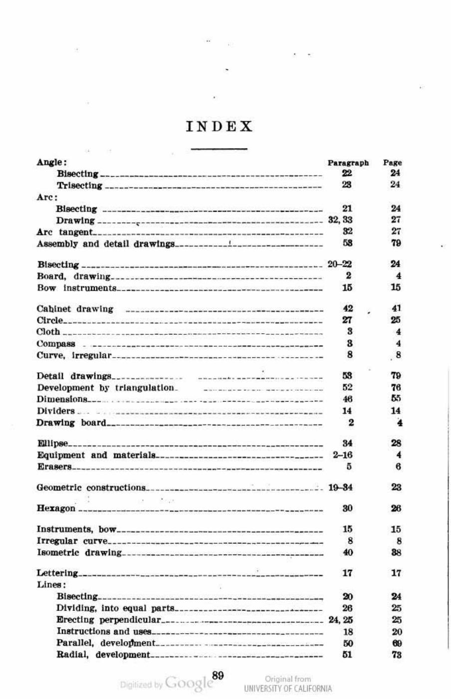
•
INDEX
AlII1@: Blloeeliog __ • ________________________________________ _ TrI.eeUq ____ ________ ______ • ________________ ___ ____ _
Biaectint' --------.------------------------------------D .... Ln&' _. ___ _ • _< _________ ______ __ _________________ __ _
Are tangent ____ ______________ __ _____________ __________ __ __ _
A_mb1,. and detail dra"'IIlP _____ ___ ___ i ____ _____ ~ _____ _
" 32." " ..
BlfJeCtinc _____ __ __ • ______________________ _____________ 20-22 no.rd, drawhll. __ ________ ____ _____ __________ ___ __ _ _____ ___ 2 80", 11I8t rumen ta. ______ ___ • _ _ _ ___ ___ _ _ ____ _ ___ __ __ _ _ __ ____ 16
CQbLtHlt drlt"'lng -------------------------------------_.--CircLe _________ ______ ____ ____________ ________ ____ ______ __ __ _ Cloth __ __ ____ ____ ___ ____ _____ ______ __ __ _____ __ __ _____ ___ __ _
t.'ompu8 Curve,
Irrecu htr __________________ __ __ ___________ _
Detail dra"IDCI! ______ ____ __ _
Development b )' trlllngllhlt!OIL DlWeDsl(ms.. __
----------- -------- ---- --- --------------
OI .. I(JeMl
DMl.w11l&' boand _______________________ ____ ______ __ _______ _
EIIllpee ______________________________ ________ _________ _____ _
&q III pm@Dt 11.00 ma terl a IL ____ ____________________ _________ _ ErIl8eMl. ________ ____ ______ ______ ____ ___ __________ __________ _
Geometrle (.'<matructIOfl.l ___ ___________________ ______ ______ __ _
U .. :u.goD' ___________ ____ ___ ___ _______ _____________ _______ _
In!trun>enta, 00" _______________________________________ _ I~Lar curve __ ____ ___ ~ ___ _______ ______________ ____ ___ _ _
I.ometrle d ra"IDg ____ _________________ _____ _________ ~-----
LetterIDI _____________ ~ __ _______ _____________ : ___________ _
Llnell: BII,ectlna _____________________ ____ _____ _________ __ ~ ___ _
Into 9qllal partA- _____ ____ ___________________ _
" '" • B B ..
"' ., " , ..
.. " ,
" B .. ., " Dividing,
Erecllol" pe..,endlcular ___ ___ ________ __________________ _ .....
lnttructlon. and u _ ______ _______________________ ______ _
Parallel, Radial,
deo'elotfment __ _______ . _ deveJopmeuL ______ ___ __ .
(
,--------------------------------------._----
89 o,'gir .11..UNM~\ITY Of (AllfORN IA
" SO
"
,. " " " ,. • " ., .. • • , " " ., U • " • 6 .. .. " , .. ,. .. .. '" .. "
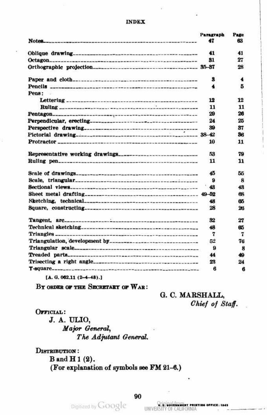
",.n
Not".~_~ ___ ~ _____________________________ _____ _____ ____ _ '.. Oblique dnw1na____________________________________ ______ f1 41 <ktaaoll________________________________ ____ __ __ ___ _________ 11 27 Orlt\ocJ'apbk: projectlon.... __ ____________ _____ ______________ ~ 28
Paper and eloth __ ___ _______ ____ ____________ _____ ________ __ _ Po-oclla ________________ __ ___ ____ _____________ _____ ___ ____ _ .... ,
Lettel"lnc - - ----------- - ------------------ - ----------- - -RIIIIII( _________ • ___ • •. ___ ___ ______ ____ " ________ ______ _
~~---------------------,--- --------------- - -- -- ----- -
• • .. n ..
• , " II ..
PdpMCIlcular, tlllCtlnc ___ n __ nn __ _ un ___ h __ _ _ n n __ n _ _ 2t 25
Pe ........ U"' dI"l.W'lIInn __ __ n_n_nh _ nn_n_ h nn_n_ n 88 S7 Pictorl.ll d ... "'I". __ n _ ____________ ___ ____ h ___________ ~nn S8 .:l 86 Prolra~tor ___________ ___ _____________ _____ ______________ 10 U
Re ... ·· JDtatl"' worldIII' drawlllP-___ n __ nn __ _ n _ _ nnn_
HullllI pe!l _____ ______________ ___ _______ _ _____________ _ _ _ __ _ '" II " II
s...le of drawlDp____ ____________________________ ____ ______ o6lI Gr. Seale, u1alWUlar ___________ _______ ______ _________ ___ ~______ II 8 8ecttonal "'__________ ________________ _______ __ ____ ___ ____ . 408 .. , Sbeet _al dratthll ______ ______ _________ ________ ________ __ 49-!i2 88 Hketchm,:. technlc-I _____ n _______________ _ ______ n ____ 48 IXi Square. collltr\lCtIq.. ________ _______ ______ ____ _____ _ *_______ 28 .I!tI
Ta~t. ~ ______ _______ ___ ~ ______ ___ ______ _______ .. __ ___ lI2 27 Tec'hnbl aketchlllC- _______________ _________ ___ ____ ~ _ _ _____ 48 IXi TrhlqlN __ ______________ __ __________ ____ _________ ___ ____ _ 7 7
TTianplaiioo. ·de1'elopmenl hJ'____ ___ ____ __ ___ ___ __ ______ ___ (j:! 711 Trlanplu _Ie ____ n ___ n ___ n ____ n _________ n ____ II 8 Treaded PIIrtL ________________ _____ _ ~ __ _______ _______ ______ 4f, ..
't'rhoecllnc a rlCht 1.JlI1e..._______ _____________________________ 2.'1 J.l4 T «JUllre___________________________________________________ 6 t
t • . G.Oft.l1 (2 I 1').1
By (IJIDQ or TB1t 8A:un~i • .dT or W <I..:
()pnCL\L: J . A. ULIO.
Jlajtw OeMral, TM .d.d;Uttmt General..
DumtnstmON :
BandHl (2).
O. C. MARSHATJ., Ohief 0/ Stal .
(For es:plan,tion of symbols _ FM 21-8.)
90 t., .............. - - - '