fulton vertical coil design thermal fluid heaters · fulton thermal corp. *vertical coil thermal...
TRANSCRIPT
Fulton Thermal Corp. *Vertical Coil Thermal Fluid Manual* Version 2009-0929 Page 1
Fulton Vertical Coil Design Thermal Fluid Heaters
(Models FT-C & FT-S)
Installation, Operation and Maintenance Manual
Fulton Thermal Corp. 972 Centerville Road Pulaski, NY 13142 Telephone: (315) 298-5121 Facsimile: (315) 298-6390 www.fulton.com
Serial # __________________________ Model # __________________________ Fulton Order # __________________________ Sold To __________________________ Job Name __________________________ Date __________________________

Fulton Thermal Corp. *Vertical Coil Thermal Fluid Manual* Version 2009-0929 Page 2
Fulton Thermal Corp. *Vertical Coil Thermal Fluid Manual* Version 2009-0929 Page 3
Table of Contents
Section 1 – Safety Warnings & Precautions
Section 2 – Installation 1. Component View
2. Placement
3. Location
4. Approximate Floor Loadings
5. Minimum Make-Up Air
6. Access
7. Circulating Pump
8. Combination Thermal Buffer Tank
9. Pressurized Systems
10. Connections
11. Conditions
12. Pipework Systems
13. General
14. Equipment
15. Piping
16. Gasket Installation
17. Piping
18. System Connections
19. Heater Connections
20. Gauges
21. Valves
22. Testing
23. Insulation
24. Thermal Fluids
Section 3 – Operation 1. Start Up Preparation & Installation
Review
2. Preparation
3. Filling the System
4. For Systems Equipped with Inert
Blankets
5. Circulating Pump
6. Initial Start Up
7. Start Up Service
8. Cold Circulation
9. Filtering the System
10. Firing the Heater/Heater
11. Procedure for First Shutdown
12. Required Pressure Drop Across the
Heater
13. Burner Cycles
14. Linkageless Modulation
15. Nexus Display
16. Siemens Linkageless Modulation
17. On/Off Burner
18. Oil Fired Burner
19. Dual Fuel Burner
20. Operating Controls
21. Daily Start Up
22. Daily Shutdown
Section 4 – Maintenance 1. Required Maintenance at First
Shutdown
2. General Maintenance Schedule
3. Maintenance Procedures
4. Safety Check Procedures
5. Recommended Maintenance Schedule
6. Troubleshooting
7. Fulton Thermal Fluid Heater Log Sheet
Section 5 – Parts & Warranty Section 6 – Product Specs & Data

Fulton Thermal Corp. *Vertical Coil Thermal Fluid Manual* Version 2009-0929 Page 4
Fulton Thermal Corp. *Vertical Coil Thermal Fluid Manual* Version 2009-0929 Page 5
Section 1

Fulton Thermal Corp. *Vertical Coil Thermal Fluid Manual* Version 2009-0929 Page 6
Fulton Thermal Corp. *Vertical Coil Thermal Fluid Manual* Version 2009-0929 Page 7
Section 1 – Safety Warnings & Precautions Prior to shipment, the following tests are made to assure the customer the highest standards of
manufacturing:
a) Material inspections
b) Manufacturing process inspections
c) ASME welding inspection
d) ASME hydrostatic test inspection
e) Electrical components inspection
f) Operating test
g) Final engineering inspection
h) Crating inspection
Rigging your heater into position should be handled by a competent rigger experienced in
handling heavy equipment.
The customer should examine the heater for any damage, especially the refractories. It is the responsibility of the installer to ensure all parts supplied with the heater are fitted in a correct and safe manner.
Warning
Operating the heater beyond its design limits can damage the heater, it can also be dangerous. Do not operate the heater outside its limits. Do not try to upgrade the heater performance by unapproved modifications. Unapproved modifications can cause injury and damage. Contact your Fulton dealer before modifying the heater.
Warning
A defective heater can injure you or others. Do not operate a heater which is defective or has missing parts. Make sure that all maintenance procedures are completed before using the heater. Do not attempt repairs or any other maintenance work you do not understand. Obtain a Service Manual from Fulton or call a Fulton Service Engineer.
Warning
Thermal Fluid Heaters have high temperature surfaces, that if touched may cause serious burns. Only competent and qualified personnel should work on or in the locality of a thermal fluid heater and ancillary equipment. Always ensure the working area and floor are clear of potential hazards, work slowly and methodically.
Fulton Thermal Corp. *Vertical Coil Thermal Fluid Manual* Version 2009-0929 Page 8
WARNING: If the information in this manual is not followed exactly, a fire or explosion may result causing property damage, personal injury or loss of life.
- Do not store or use gasoline or other flammable vapors and liquids in the vicinity of this or any
other appliances.
- WHAT�TO�DO�IF�YOU�SMELL�GAS
• Do not try to light any appliance.
• Do not touch any electrical switch; do not use any phone in your building.
• Immediately call your gas supplier from a neighbor’s phone. Follow the gas
supplier’s instructions.
• If you cannot reach your gas supplier, call the fire department.
- Installation and service must be performed by a qualified installer, service agency or the gas
supplier. For Your Safety
The following WARNINGS, CAUTIONS and NOTES appear in various chapters of this manual.
They are repeated on these safety summary pages as an example and for emphasis.
• WARNINGS must be observed to prevent serious injury or death to personnel.
• CAUTIONS must be observed to prevent damage or destruction of equipment or loss of
operating effectiveness.
• NOTES must be observed for essential and effective operating procedures, conditions,
and as a statement to be highlighted.
It is the responsibility and duty of all personnel involved in the operating and maintenance of this
equipment to fully understand the WARNINGS, CAUTIONS and NOTES by which hazards are to
be eliminated or reduced. Personnel must become familiar with all aspects of safety and
equipment prior to operation or maintenance of the equipment.
Note
The installation of a barometric stack regulator is recommended at all installations.
Note
If the tank is located outdoors nitrogen is required.
Fulton Thermal Corp. *Vertical Coil Thermal Fluid Manual* Version 2009-0929 Page 9
Note
Non-code tanks cannot be pressurized over 15 psig.
Warning
High temperature thermal fluid, steam and combustible vapors may be vented through the vent connection on the combination dearetor/thermal buffer/expansion tank.
Warning
Once the system has been filled, any modification to the tank or connected piping requires purging of the work area to prevent ignition of potentially flammable vapors. Consult factory prior to beginning work. Consult MSDS for your thermal fluid for flammability limits.
Note
If the circulating pump motor is not supplied by Fulton Thermal Corporation, the motor starter will not be supplied.
Note
Low emissions burners for all models require 10 psi gas pressure.
Note
With the exception of the duct run previously described, horizontal sections of ducting must be avoided and should not exceed four feet total.
Note
The system pump is not to be used to fill the system.
Caution
For reasons of safety, the hot exhaust gas duct and chimney must be insulated or shielded within the locality of the heater.
Caution
During operation, any leaks are usually detected by a small amount of vapor. Leaks should be attended to as soon as possible because under certain circumstances, such as saturated insulation, thermal fluid can ignite when exposed to air and heat.
Note
Fulton Thermal Corporation cannot be held responsible in the case of accident or damage resulting from the use of inadequate fluid.
Fulton Thermal Corp. *Vertical Coil Thermal Fluid Manual* Version 2009-0929 Page 10
Note
Unless specially filtered, compressed air will introduce moisture into the system. Dry air or Nitrogen is recommended.
Note
Some plastics can be dissolved by thermal fluid.
Note
Do not use system circulating pump for system filling.
Note
A pump that has been used for water or a different thermal fluid should not be used prior to extensive cleaning. Thermal fluid can be damaged by contact with moisture or other fluids.
Warning
Pressurizing a drum to force fluid into the system is not recommended. The drum can easily explode, creating a hazard to personnel and equipment.
Note
Tanks are non-code as a standard. Non-code tanks cannot be pressurized over 15psig. Tanks built to ASME code Section VIII Div 1 are available upon request.
Note
Do not run the pump before filling it with fluid.
Caution
1. Use extreme caution opening plug when system temperature is elevated. 2. Wear eye and hand protection. 3. Back the plug out slowly to the last two or three threads. Allow any pressure under
plug to bleed slowly to prevent a spray of hot oil.
Warning
During a system boil out, it is imperative that all system legs or paths are open to flow to ensure no water is trapped in the system.
Warning
Never open a cool or unheated user leg of a system when the rest of the system is above 250°F.
Fulton Thermal Corp. *Vertical Coil Thermal Fluid Manual* Version 2009-0929 Page 11
Note
Do not open drain or vent valves during operation.
Note
If excessive amounts of thermal fluid is vented from the system, additional thermal fluid may be required in the system.
Note
Flash steam may be generated at any point up to the operating temperature. Watch for gauge fluctuations.
Note
Start-up technician should verify that all valves are opened prior to establishing flow and heat-up.
Note
If fluid or piping is added to the system the boil out procedure must be followed as water has to be introduced into the system.
Note
If the burner loses flame while driving to a point then:
• Turn the main ON/OFF switch to OFF. Reset the loss of flame fault. Press Escape on the AZL once. Press Enter on the AZL to reset the control. The red light on the panel box door should go out.
• Adjust the air and gas servos for that point while the burner is off. Follow steps 28-29.
• Turn the main ON/OFF switch to ON.
Note
As soon as a servo position is altered, the servo will move to that position. Only change servo settings by a maximum of 0.5° at a time before verifying combustion.
Caution
The heater emissions may not be correct after changing the servo motor. Verify the emissions throughout the range of modulation. If emissions are off, the servo motor can be adjusted by following the procedure in the Commissioning the Heater section of this manual.
Note
Use extreme caution to avoid contact with the cleaning solution.
Fulton Thermal Corp. *Vertical Coil Thermal Fluid Manual* Version 2009-0929 Page 12
Note
Refer to local regulations for disposal of caustic solution.
Note
All of the above maintenance procedures should be completed by trained personnel. Appropriate training and instructions are available from the Fulton Service Department at (315) 298-7148 or your local Fulton Thermal Representative.
Note
Since unit lights at low fire, it may be necessary to increase high gas pressure setting or jumper contacts to allow unit to modulate to where modulation gas valve back pressure is lessened.
Note
Room temperature not to exceed 100o F.
Fulton Thermal Corp. *Vertical Coil Thermal Fluid Manual* Version 2009-0929 Page 13
Section 2

Fulton Thermal Corp. *Vertical Coil Thermal Fluid Manual* Version 2009-0929 Page 14
Fulton Thermal Corp. *Vertical Coil Thermal Fluid Manual* Version 2009-0929 Page 15
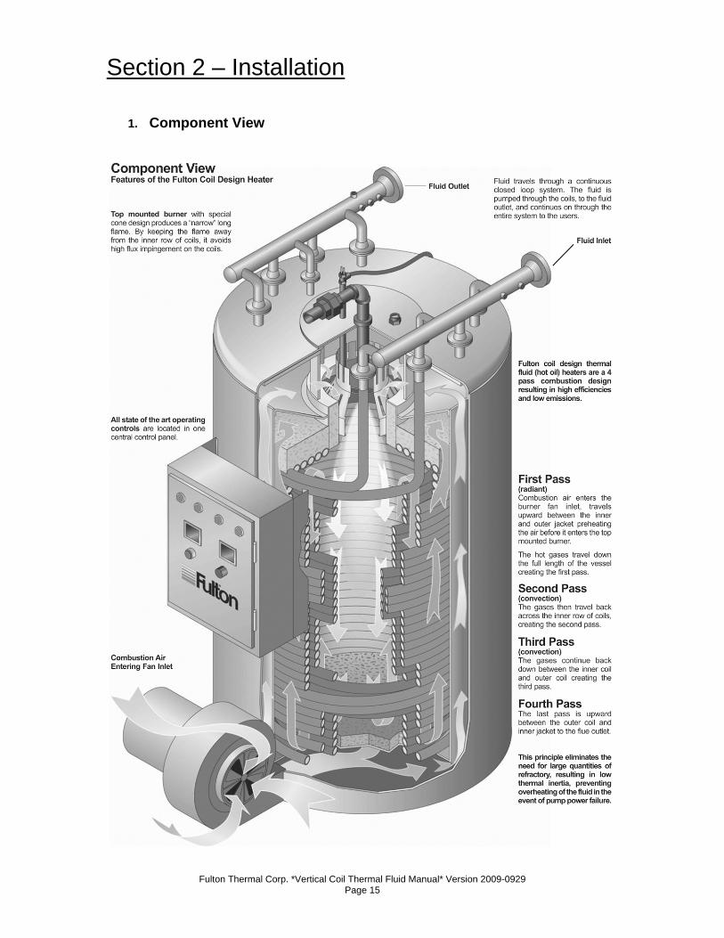
Section 2 – Installation
1. Component View
Fulton Thermal Corp. *Vertical Coil Thermal Fluid Manual* Version 2009-0929 Page 16
2. Placement a) Proper placement of your Fulton Thermal Fluid Heater is essential. Attention paid
to the following points will save a great deal of difficulty in the future. Correct
placement is the first step to trouble-free installation, operation and maintenance.
b) All Fulton Vertical Coil Design Heaters are shipped vertically and all units are
crated for forklift transport. Once uncrated, all units with the exception of
freestanding models FT-0080C, FT-0120C, FT-0160C and FT-0240C can be
transported with a forklift.
c) These four models can only be lifted for unloading and moving by means of lifting
lugs at the top of the heaters. If means of lifting are not available, rollers should
be placed beneath the frame of the heater, and it should be guided to the
position of where it is to be installed. Under no circumstances should weight be
allowed to bear on the jacket, control panel or fan housing of any Fulton Thermal
Fluid Heater.
d) All stand alone heaters can be moved via a crane utilizing the lifting lugs on top
of the heater. The FT-0320C and larger stand alone heaters can also be moved
using a fork lift. All skidded units can be moved with forklifts.
3. Location a) Authorities with jurisdiction over any national or local codes which might be
applicable to thermal fluid applications should be consulted before installations
are made.
b) The heater should be located as close as possible to the place where the heat
will be used in order to keep pipe work costs to a minimum.
c) A level, hard, non-combustible surface is required for a suitable base for
mounting the unit. It is suggested that a four inch curb be installed completely
around the unit. In the event of a large spill, this will help contain the fluid.
d) Approximations for the floor loading of each heater are given in the floor loadings
table. Check building specifications for permissible floor loading.
e) The heater should be placed in a suitable heater house or well ventilated
separate room through which personnel do not normally pass. This is not
essential, but the layout should eliminate traffic in potentially hazardous areas.
For instance, the service engineer or the operator should not have to pass
exposed, hot pipe work to make adjustments to the heater controls.
f) Ventilation must be sufficient to maintain a building temperature of 100°F. or less
and the panel box temperature must not exceed 125°F. Natural ventilation should
be provided by means of grills at floor and ceiling level.
Fulton Thermal Corp. *Vertical Coil Thermal Fluid Manual* Version 2009-0929 Page 17
g) To burn fuel properly, the burner must have an adequate supply of air. The
bottom vent should be sized to allow a minimum of 0.4 square inch of opening for
every 1,000 BTU/hr. input of fuel (10 cm2/1000 kcal/hr). The upper vent should
be at least one third this size. See table for minimum make up air required and
the recommended area of opening for each heater.
h) If positive forced ventilation is adopted, you must ensure that there will be no
appreciable pressure variation in the heater room.
Note
The installation of a barometric stack regulator is recommended at all installations.
i) Artificial ventilation by extraction of air is not recommended. This method of
ventilation can create a negative pressure in the building which will seriously
affect combustion and proper operation of the stack. Please note that exhaust
fans or similar equipment can create a down draft in the chimney or starve the
burner’s air supply. Either case may result in poor combustion or nuisance
failures. A properly designed make-up air system in the heater room will preclude
these possibilities and is required to maintain proper combustion.
j) In addition, an exhaust fan may draw products of combustion into the work
environment creating a possible hazard to personnel.
k) It is essential that only fresh air be allowed to enter the combustion air system.
Foreign substances, such as combustible volatiles and lint in the combustion
system can create hazardous conditions.
Note
When calculating ventilation requirements, heat losses from the Fulton equipment (and other equipment) should be considered.
Fulton Thermal Corp. *Vertical Coil Thermal Fluid Manual* Version 2009-0929 Page 18
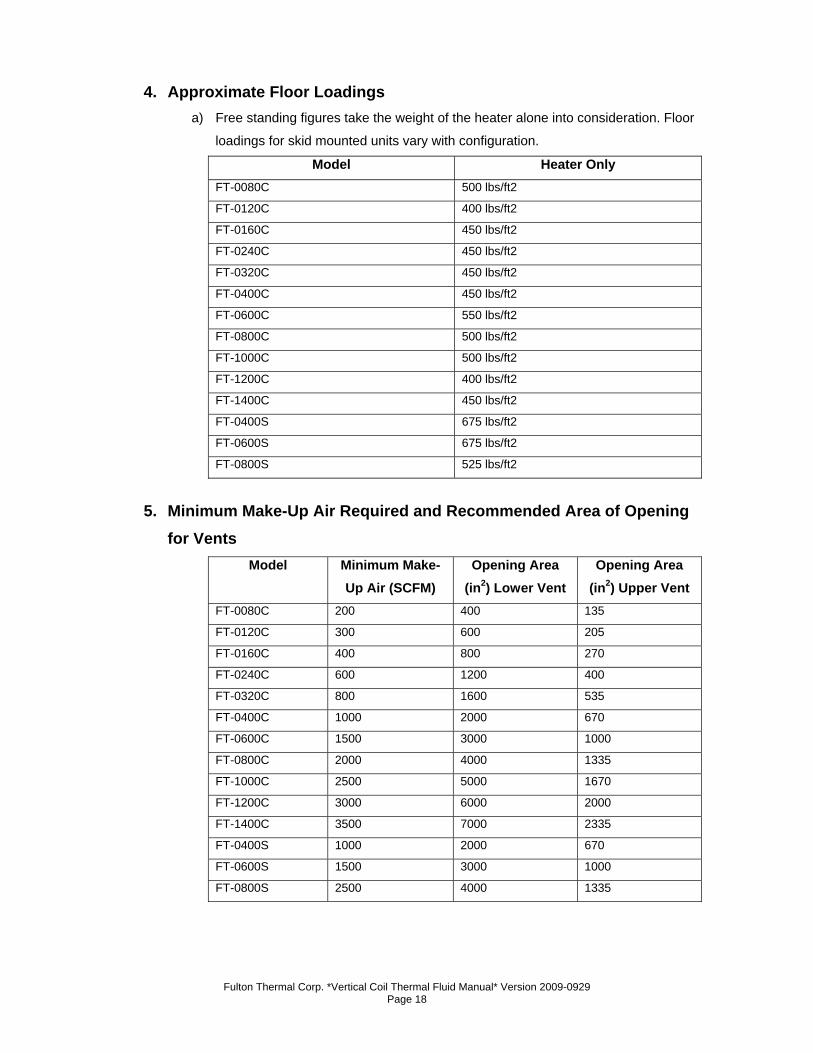
4. Approximate Floor Loadings a) Free standing figures take the weight of the heater alone into consideration. Floor
loadings for skid mounted units vary with configuration.
Model Heater Only FT-0080C 500 lbs/ft2
FT-0120C 400 lbs/ft2
FT-0160C 450 lbs/ft2
FT-0240C 450 lbs/ft2
FT-0320C 450 lbs/ft2
FT-0400C 450 lbs/ft2
FT-0600C 550 lbs/ft2
FT-0800C 500 lbs/ft2
FT-1000C 500 lbs/ft2
FT-1200C 400 lbs/ft2
FT-1400C 450 lbs/ft2
FT-0400S 675 lbs/ft2
FT-0600S 675 lbs/ft2
FT-0800S 525 lbs/ft2
5. Minimum Make-Up Air Required and Recommended Area of Opening for Vents
Model Minimum Make-Up Air (SCFM)
Opening Area (in2) Lower Vent
Opening Area (in2) Upper Vent
FT-0080C 200 400 135
FT-0120C 300 600 205
FT-0160C 400 800 270
FT-0240C 600 1200 400
FT-0320C 800 1600 535
FT-0400C 1000 2000 670
FT-0600C 1500 3000 1000
FT-0800C 2000 4000 1335
FT-1000C 2500 5000 1670
FT-1200C 3000 6000 2000
FT-1400C 3500 7000 2335
FT-0400S 1000 2000 670
FT-0600S 1500 3000 1000
FT-0800S 2500 4000 1335
Fulton Thermal Corp. *Vertical Coil Thermal Fluid Manual* Version 2009-0929 Page 19
6. Access a) Access around the heater should be provided to facilitate maintenance.
Appropriate clearances for all sides follow.
b) Place heater with clearances to unprotected combustible materials, including
plaster or combustible supports, not less than the following:
1. Heater Front 36” (1m)
2. Heater Sides 18” (.5m)
3. Heater Rear 18” (.5m)
4. Flue Pipe 18” (.5m)
5. Heater Top 60” (1.52m)*
6. *For burner removal. Burners may weigh up to 550 lbs.
depending on the type and configuration. Customer to provide
adequate means of burner removal.
c) All heaters will also require a minimum clearance of 5’ overhead for personnel
access and burner removal. In cases where the available height is insufficient, a
roof or ceiling trap might be considered.
d) Pipes should not be run within ten inches of any control cabinets or combustible
material.
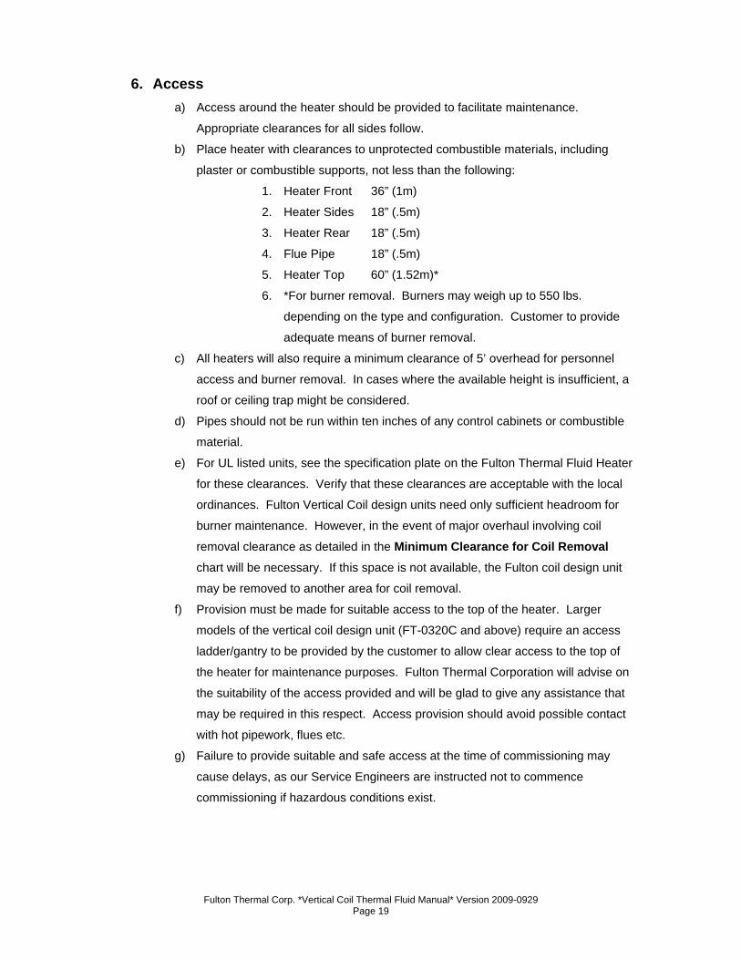
e) For UL listed units, see the specification plate on the Fulton Thermal Fluid Heater
for these clearances. Verify that these clearances are acceptable with the local
ordinances. Fulton Vertical Coil design units need only sufficient headroom for
burner maintenance. However, in the event of major overhaul involving coil
removal clearance as detailed in the Minimum Clearance for Coil Removal chart will be necessary. If this space is not available, the Fulton coil design unit
may be removed to another area for coil removal.
f) Provision must be made for suitable access to the top of the heater. Larger
models of the vertical coil design unit (FT-0320C and above) require an access
ladder/gantry to be provided by the customer to allow clear access to the top of
the heater for maintenance purposes. Fulton Thermal Corporation will advise on
the suitability of the access provided and will be glad to give any assistance that
may be required in this respect. Access provision should avoid possible contact
with hot pipework, flues etc.
g) Failure to provide suitable and safe access at the time of commissioning may
cause delays, as our Service Engineers are instructed not to commence
commissioning if hazardous conditions exist.
Fulton Thermal Corp. *Vertical Coil Thermal Fluid Manual* Version 2009-0929 Page 20
Minimum Clearance for Coil Removal
Model Inches Meters
FT-0080C 60 1.6
FT-0120C 66 1.7
FT-0160C 66 1.7
FT-0240C 73 1.9
FT-0320C 80 2.0
FT-0400C 94 2.4
FT-0600C 124 3.2
FT-0800C 126 3.2
FT-1000C 126 3.2
FT-1200C 126 3.2
FT-1400C 140 3.6
FT-0400S 124 3.2
FT-0600S 124 3.2
FT-0800S 126 3.2
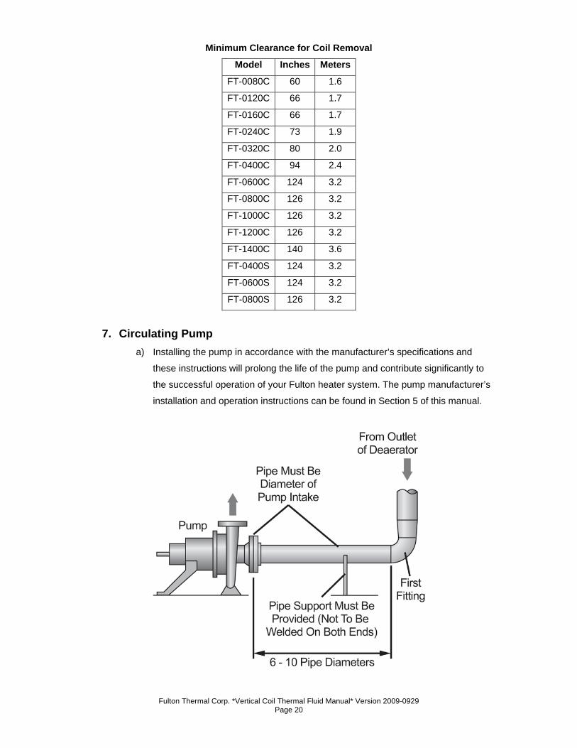
7. Circulating Pump a) Installing the pump in accordance with the manufacturer’s specifications and
these instructions will prolong the life of the pump and contribute significantly to
the successful operation of your Fulton heater system. The pump manufacturer’s
installation and operation instructions can be found in Section 5 of this manual.
Fulton Thermal Corp. *Vertical Coil Thermal Fluid Manual* Version 2009-0929 Page 21
b) Location
1. The pump should be located adjacent to the heater. Its base
must be firm, level (preferably concrete), and free from vibration.
c) Connections & Piping
1. The pump should be routed as per the manufacturer’s
requirements. It should be equipped with flexible connections at
the suction and discharge sides. The primary function of these
connections are to prevent stresses due to pipe expansion from
being placed on the pump and to isolate pump vibrations from
the pipe work and the heater. They also allow for expansion and
deflection of the pipe work. These connections should be rated
for high temperature since they are considered part of the piping
system.
2. The suction pipe work must be directly connected to the
deaerator section via a vertical run with as few elbows as
possible, and should contain the strainer and an isolating valve.
The discharge pipe work must be connected directly to the
heater inlet, and should contain an isolating valve. See that pipe
work connections match up accurately with pump flanges. Refer
to the pump manufacturer’s recommendations for the specific
pump inlet piping requirements. Typically these requirements are
that:
a. It be a straight run of pipe.
b. The straight run from the pump inlet to the first fitting,
valve, or flex connector be a minimum of 6-10 pipe
diameters in length.
c. The pipe used should be the same size as the inlet of
the pump.
3. The piping in the immediate vicinity of the pump must not be
supported by the pump. The pump is not designed to bear the
weight of the piping, and weight on any part of the pump will
throw it out of alignment.
Fulton Thermal Corp. *Vertical Coil Thermal Fluid Manual* Version 2009-0929 Page 22
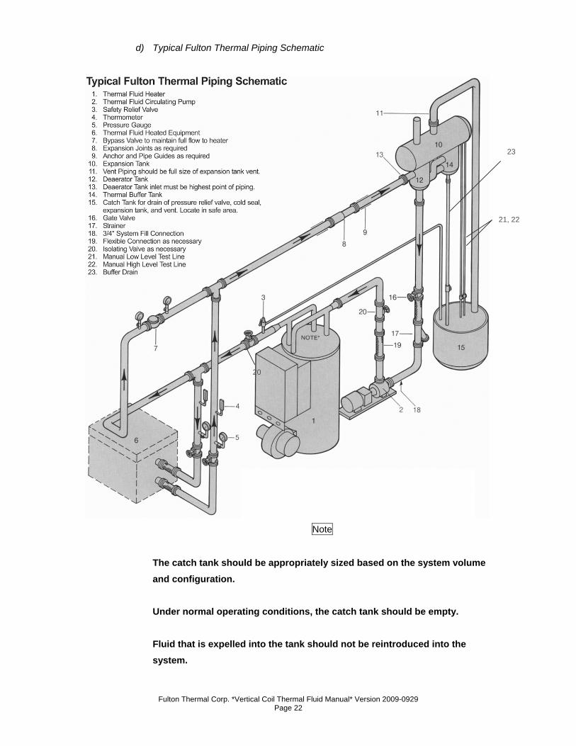
d) Typical Fulton Thermal Piping Schematic
Note
The catch tank should be appropriately sized based on the system volume and configuration.
Under normal operating conditions, the catch tank should be empty.
Fluid that is expelled into the tank should not be reintroduced into the system.
20
21, 22
23
Fulton Thermal Corp. *Vertical Coil Thermal Fluid Manual* Version 2009-0929 Page 23
e) Alignment
1. Proper alignment directly affects bearing, coupling, and seal life
expectancy. The pump is properly aligned before it leaves the
factory. Because the system expands in operation, pump must
be realigned when the system is at operating temperature.
2. The coupling alignment of the pump and driver must be carefully
checked for angular and axial alignment. Check pump
manufacturers instructions for these specifications. The use of a
dial indicator to check the axial and angular alignment is
recommended.
f) Lubrication
1. An air cooled pump does not have an oiler. This type of pump
has a sleeve bearing which is, like the seals, lubricated by
thermal fluid. An air cooled pump has a grease nipple located at
the drive end of the pump near the coupling connection. This
comes pre-greased, and should be greased at intervals as
recommended by the manufacturer.
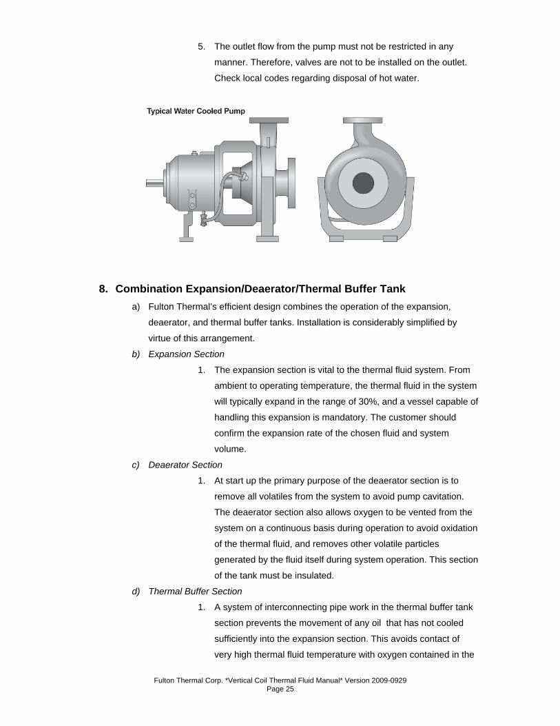
2. An oiler is shipped with each water cooled pump and it should be
filled with a lubricating oil recommended by the manufacturer.
The suggested lubricant is usually SAE-30 non-detergent oil.
Thermal fluid is not sufficient lubrication for bearings.
g) Seals
1. All seals on air cooled pumps are lubricated by thermal fluid,
therefore the pump must never be run dry, i.e., without thermal
fluid in it.
2. Filling a pump equipped with either a Grafoil packed or
mechanical seal with thermal fluid will ensure lubrication.
However, in order to be certain that all seals on an air cooled
pump are coated with thermal fluid, the pump must be bled.
3. Grafoil packings require a run-in procedure. Typically, pumps
with these seals are shipped with four or five rings installed and
several rings loose. These extra rings must be on hand for the
initial run-in procedure. See manufacturer’s instruction manual
for this procedure.
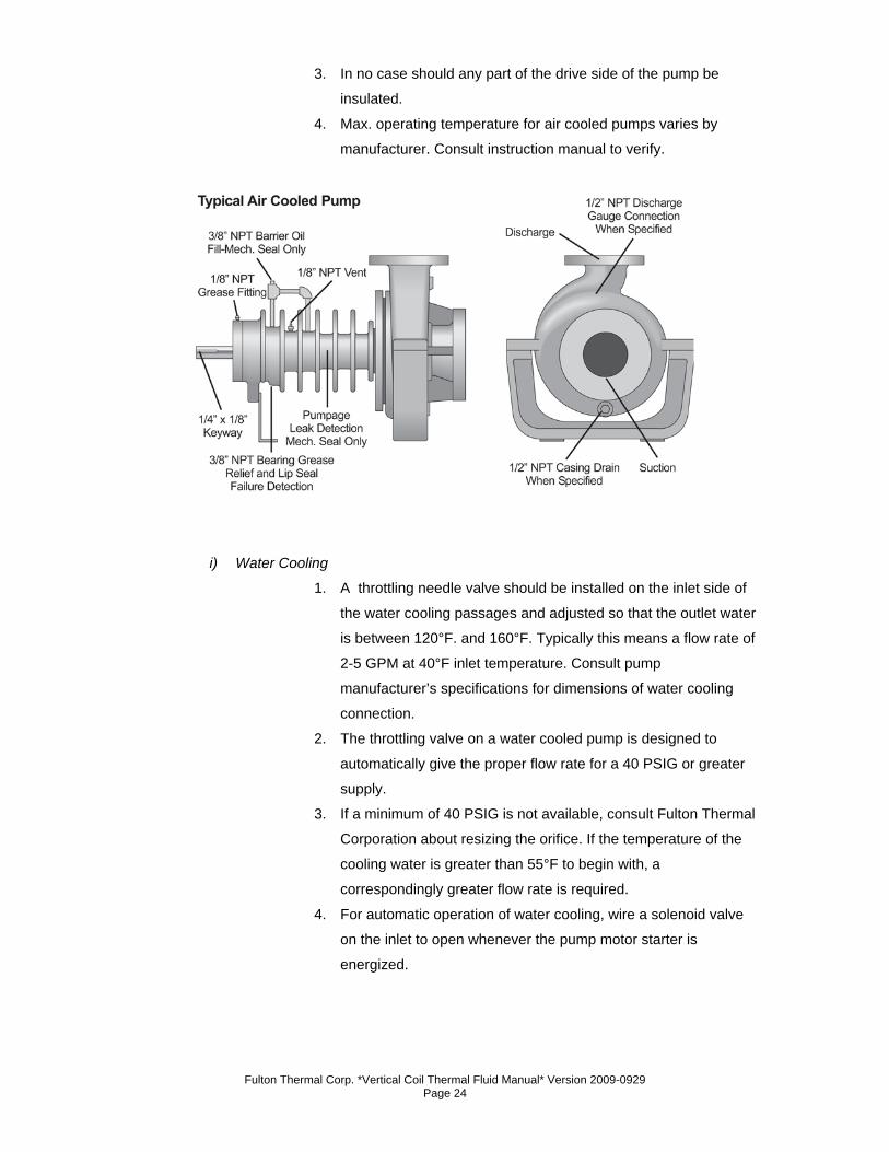
h) Air Cooling
1. Allow for free air flow around the entire pump casing at all times.
2. Max. room temperature should be 100°F.
Fulton Thermal Corp. *Vertical Coil Thermal Fluid Manual* Version 2009-0929 Page 24
3. In no case should any part of the drive side of the pump be
insulated.
4. Max. operating temperature for air cooled pumps varies by
manufacturer. Consult instruction manual to verify.
i) Water Cooling
1. A throttling needle valve should be installed on the inlet side of
the water cooling passages and adjusted so that the outlet water
is between 120°F. and 160°F. Typically this means a flow rate of
2-5 GPM at 40°F inlet temperature. Consult pump
manufacturer’s specifications for dimensions of water cooling
connection.
2. The throttling valve on a water cooled pump is designed to
automatically give the proper flow rate for a 40 PSIG or greater
supply.
3. If a minimum of 40 PSIG is not available, consult Fulton Thermal
Corporation about resizing the orifice. If the temperature of the
cooling water is greater than 55°F to begin with, a
correspondingly greater flow rate is required.
4. For automatic operation of water cooling, wire a solenoid valve
on the inlet to open whenever the pump motor starter is
energized.
Fulton Thermal Corp. *Vertical Coil Thermal Fluid Manual* Version 2009-0929 Page 25
5. The outlet flow from the pump must not be restricted in any
manner. Therefore, valves are not to be installed on the outlet.
Check local codes regarding disposal of hot water.
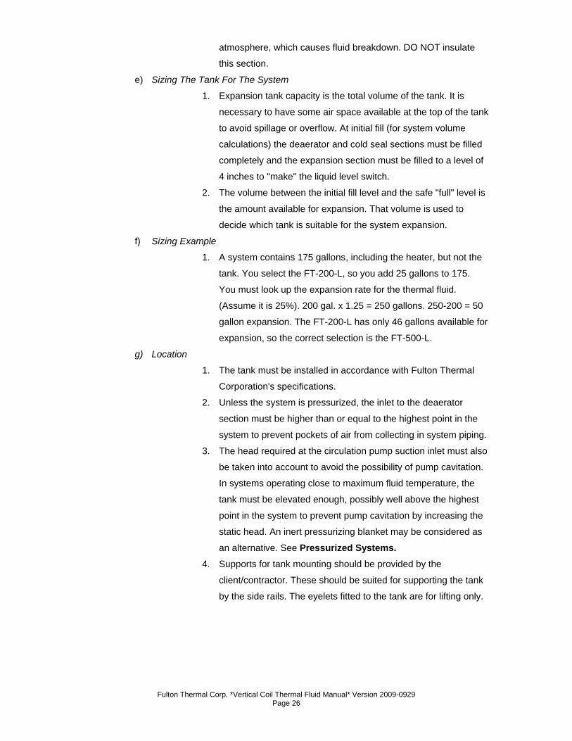
8. Combination Expansion/Deaerator/Thermal Buffer Tank a) Fulton Thermal’s efficient design combines the operation of the expansion,
deaerator, and thermal buffer tanks. Installation is considerably simplified by
virtue of this arrangement.
b) Expansion Section
1. The expansion section is vital to the thermal fluid system. From
ambient to operating temperature, the thermal fluid in the system
will typically expand in the range of 30%, and a vessel capable of
handling this expansion is mandatory. The customer should
confirm the expansion rate of the chosen fluid and system
volume.
c) Deaerator Section
1. At start up the primary purpose of the deaerator section is to
remove all volatiles from the system to avoid pump cavitation.
The deaerator section also allows oxygen to be vented from the
system on a continuous basis during operation to avoid oxidation
of the thermal fluid, and removes other volatile particles
generated by the fluid itself during system operation. This section
of the tank must be insulated.
d) Thermal Buffer Section
1. A system of interconnecting pipe work in the thermal buffer tank
section prevents the movement of any oil that has not cooled
sufficiently into the expansion section. This avoids contact of
very high thermal fluid temperature with oxygen contained in the
Fulton Thermal Corp. *Vertical Coil Thermal Fluid Manual* Version 2009-0929 Page 26
atmosphere, which causes fluid breakdown. DO NOT insulate
this section.
e) Sizing The Tank For The System
1. Expansion tank capacity is the total volume of the tank. It is
necessary to have some air space available at the top of the tank
to avoid spillage or overflow. At initial fill (for system volume
calculations) the deaerator and cold seal sections must be filled
completely and the expansion section must be filled to a level of
4 inches to "make" the liquid level switch.
2. The volume between the initial fill level and the safe "full" level is
the amount available for expansion. That volume is used to
decide which tank is suitable for the system expansion.
f) Sizing Example
1. A system contains 175 gallons, including the heater, but not the
tank. You select the FT-200-L, so you add 25 gallons to 175.
You must look up the expansion rate for the thermal fluid.
(Assume it is 25%). 200 gal. x 1.25 = 250 gallons. 250-200 = 50
gallon expansion. The FT-200-L has only 46 gallons available for
expansion, so the correct selection is the FT-500-L.
g) Location
1. The tank must be installed in accordance with Fulton Thermal
Corporation's specifications.
2. Unless the system is pressurized, the inlet to the deaerator
section must be higher than or equal to the highest point in the
system to prevent pockets of air from collecting in system piping.
3. The head required at the circulation pump suction inlet must also
be taken into account to avoid the possibility of pump cavitation.
In systems operating close to maximum fluid temperature, the
tank must be elevated enough, possibly well above the highest
point in the system to prevent pump cavitation by increasing the
static head. An inert pressurizing blanket may be considered as
an alternative. See Pressurized Systems. 4. Supports for tank mounting should be provided by the
client/contractor. These should be suited for supporting the tank
by the side rails. The eyelets fitted to the tank are for lifting only.
Fulton Thermal Corp. *Vertical Coil Thermal Fluid Manual* Version 2009-0929 Page 27
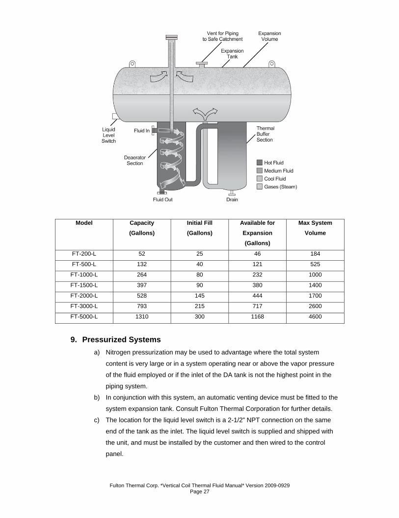
Model Capacity (Gallons)
Initial Fill (Gallons)
Available for Expansion (Gallons)
Max System Volume
FT-200-L 52 25 46 184
FT-500-L 132 40 121 525
FT-1000-L 264 80 232 1000
FT-1500-L 397 90 380 1400
FT-2000-L 528 145 444 1700
FT-3000-L 793 215 717 2600
FT-5000-L 1310 300 1168 4600
9. Pressurized Systems a) Nitrogen pressurization may be used to advantage where the total system
content is very large or in a system operating near or above the vapor pressure
of the fluid employed or if the inlet of the DA tank is not the highest point in the
piping system.
b) In conjunction with this system, an automatic venting device must be fitted to the
system expansion tank. Consult Fulton Thermal Corporation for further details.
c) The location for the liquid level switch is a 2-1/2” NPT connection on the same
end of the tank as the inlet. The liquid level switch is supplied and shipped with
the unit, and must be installed by the customer and then wired to the control
panel.
Fulton Thermal Corp. *Vertical Coil Thermal Fluid Manual* Version 2009-0929 Page 28
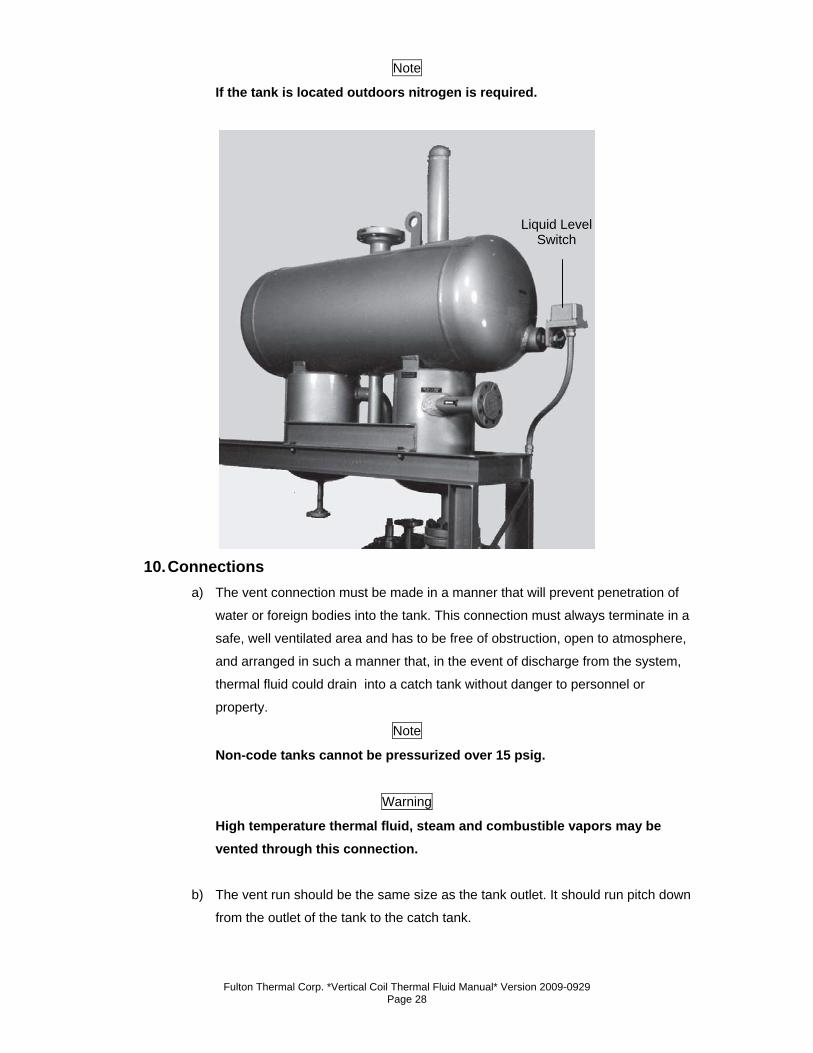
Note
If the tank is located outdoors nitrogen is required.
10. Connections a) The vent connection must be made in a manner that will prevent penetration of
water or foreign bodies into the tank. This connection must always terminate in a
safe, well ventilated area and has to be free of obstruction, open to atmosphere,
and arranged in such a manner that, in the event of discharge from the system,
thermal fluid could drain into a catch tank without danger to personnel or
property.
Note
Non-code tanks cannot be pressurized over 15 psig.
Warning
High temperature thermal fluid, steam and combustible vapors may be vented through this connection.
b) The vent run should be the same size as the tank outlet. It should run pitch down
from the outlet of the tank to the catch tank.
Liquid Level Switch
Fulton Thermal Corp. *Vertical Coil Thermal Fluid Manual* Version 2009-0929 Page 29
c) If nitrogen is used on the system, the vent can be reduced and should be piped
with a positive closing valve at the catch tank.
d) The connection between the tank outlet and the horizontal pump inlet run should
be as close to a vertical drop as possible. It should not contain an excessive
number of bends of length of pipe. These faults could encourage pump
cavitation.
e) As noted, the inlet to the deaerator must be higher than or equal to the highest
point in the system or a pressurized system must be used.
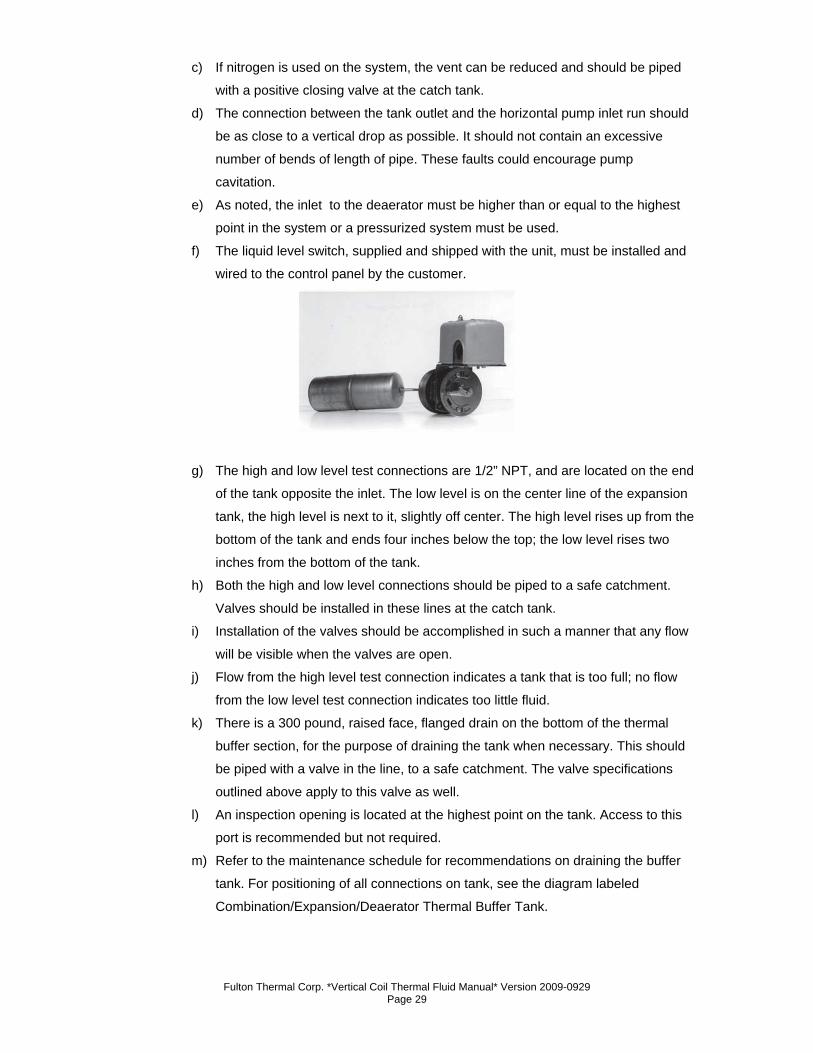
f) The liquid level switch, supplied and shipped with the unit, must be installed and
wired to the control panel by the customer.
g) The high and low level test connections are 1/2” NPT, and are located on the end
of the tank opposite the inlet. The low level is on the center line of the expansion
tank, the high level is next to it, slightly off center. The high level rises up from the
bottom of the tank and ends four inches below the top; the low level rises two
inches from the bottom of the tank.
h) Both the high and low level connections should be piped to a safe catchment.
Valves should be installed in these lines at the catch tank.
i) Installation of the valves should be accomplished in such a manner that any flow
will be visible when the valves are open.
j) Flow from the high level test connection indicates a tank that is too full; no flow
from the low level test connection indicates too little fluid.
k) There is a 300 pound, raised face, flanged drain on the bottom of the thermal
buffer section, for the purpose of draining the tank when necessary. This should
be piped with a valve in the line, to a safe catchment. The valve specifications
outlined above apply to this valve as well.
l) An inspection opening is located at the highest point on the tank. Access to this
port is recommended but not required.
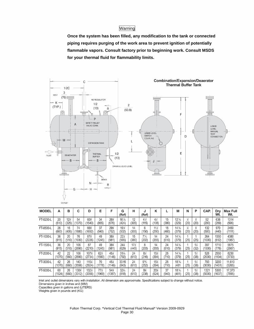
m) Refer to the maintenance schedule for recommendations on draining the buffer
tank. For positioning of all connections on tank, see the diagram labeled
Combination/Expansion/Deaerator Thermal Buffer Tank.
Fulton Thermal Corp. *Vertical Coil Thermal Fluid Manual* Version 2009-0929 Page 30
Warning
Once the system has been filled, any modification to the tank or connected piping requires purging of the work area to prevent ignition of potentially flammable vapors. Consult factory prior to beginning work. Consult MSDS for your thermal fluid for flammability limits.
Fulton Thermal Corp. *Vertical Coil Thermal Fluid Manual* Version 2009-0929 Page 31
n) Electrical Connections
1. A wall-mounted, fused disconnect sized for the unit must be
provided and fitted by the client/contractor, if a disconnect is not
supplied on the panel.
2. Fuses must be sized according to motor name plates and local
electrical codes.
3. Heaters and single skid systems are generally shipped
completely prewired. The liquid level switch on the expansion
tank, when supplied, will be shipped in the parts box and must
be installed in the field. Multiple skid systems may require wiring
between the skids.
4. If the unit is not skid-mounted at the factory, the client/contractor
is required to wire the circulating pump starter.
Note
If the circulating pump motor is not supplied by Fulton Thermal Corporation, the motor starter will not be supplied.
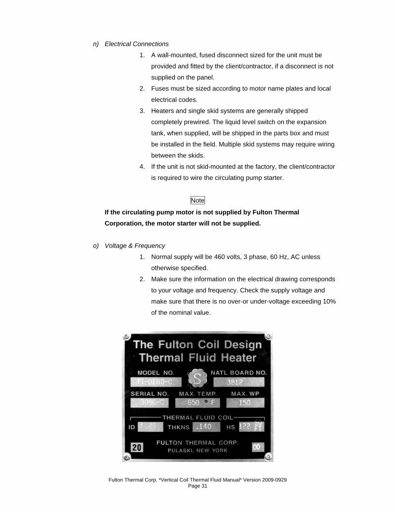
o) Voltage & Frequency
1. Normal supply will be 460 volts, 3 phase, 60 Hz, AC unless
otherwise specified.
2. Make sure the information on the electrical drawing corresponds
to your voltage and frequency. Check the supply voltage and
make sure that there is no over-or under-voltage exceeding 10%
of the nominal value.
Fulton Thermal Corp. *Vertical Coil Thermal Fluid Manual* Version 2009-0929 Page 32
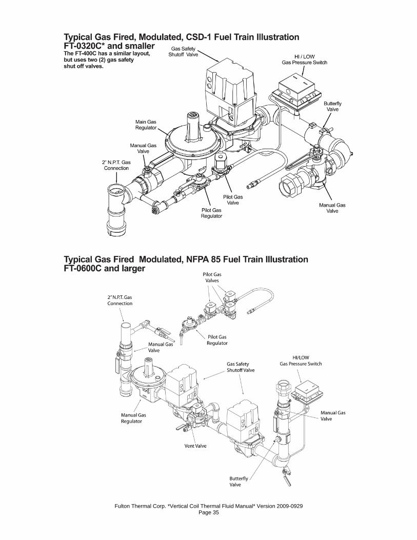
p) Fuel Connections Gas Connections
1. The burner assembly and gas controls terminate at a manual
stop valve to which the gas supply should be connected. Piping
should be sized for a gas flow consistent with the required
BTU/Hr input. Large pressure drops must be avoided.
2. Fulton Thermal Corporation recommends that the supply piping
between the pressure regulator and the inlet to the heater be
kept to a minimum.
3. The minimum required gas pressure at the stop valve varies with
the model of heater. The requirements for natural gas-fired coil
design models are as follows:
a. Models FT-0080-C to FT-0400-C and FT-0400-
S: 14” w.c.
b. Models FT-0600-C to FT-0800-C and FT-0600-S
to FT-0800-S: 40” w.c.
c. Models FT-1000-C to FT-1400-C: 120” w.c.
Note
Low emissions burners for all models require 10 psi.
4. Even when the unit is shut down, the gas supply pressure must
never exceed these values.
5. When operating, the supply pressure should not drop below
these limits:
a. Not less than 11 “ w.c. where 14” w.c is
required.
b. Not less than 30” w.c. where 40” w.c. is
required.
c. Not less than 100” w.c. where 120” w.c. is
required.
6. The supply pressure must be regulated by a non-stacking, tight,
shut-off regulator.
7. Diaphragms, gas valves, pressure regulators, and pressure
switches on all gas-fired units have vent connections which must
be vented per local code.
8. On gas fired units with NFPA 85 valve trains, there is a vent
valve which must be piped to atmosphere.
Fulton Thermal Corp. *Vertical Coil Thermal Fluid Manual* Version 2009-0929 Page 33
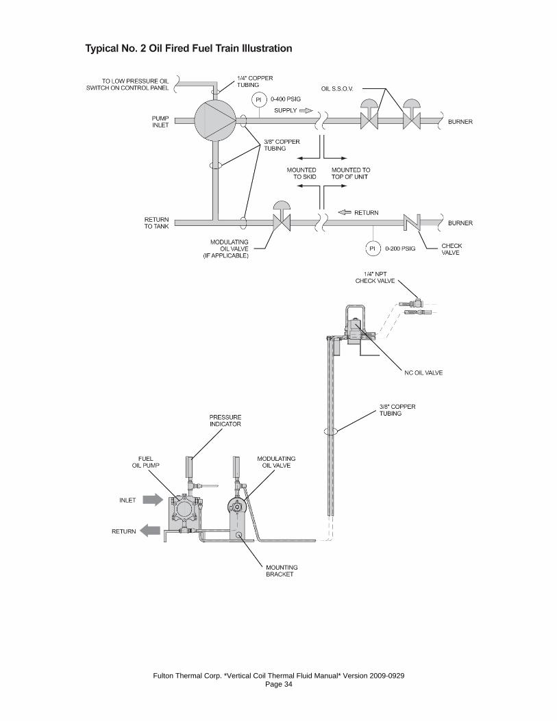
Oil Connections 9. Fuel pipes should be of approved materials and of a diameter
suitable for the quantity of oil being delivered to the burner and
the static head available. The fuel connection should be made in
accordance with the details on the enclosed fuel pump cut sheet
in Section 5. Fuel oil piping should be done in accordance with
local/national requirements. In addition, if a two pipe system is
employed, a check valve should be fitted into the return pipe.
See fuel pump cut sheet.
10. The maximum pressure allowed at the fuel oil pump inlet is
limited to 3 psig by the National Fire Protection Association
(NFPA). If for some reason the pressure of the fuel supply will
exceed this maximum, fitting a regulator to the fuel line must be
considered, e.g. when there is a tank situated with an oil level
eight feet or more above the pump.
11. On units fitted with NFPA 85 controls, ignition is obtained by
means of a gas pilot. A natural gas or LP supply is required for
these units. The required gas supply pressure is 7” w.c. If a
guaranteed supply of natural gas is not available, then a supply
of bottled gas at 11“w.c, is required. For details contact a local
liquid propane dealer.
Fulton Thermal Corp. *Vertical Coil Thermal Fluid Manual* Version 2009-0929 Page 34
Fulton Thermal Corp. *Vertical Coil Thermal Fluid Manual* Version 2009-0929 Page 35
Fulton Thermal Corp. *Vertical Coil Thermal Fluid Manual* Version 2009-0929 Page 36
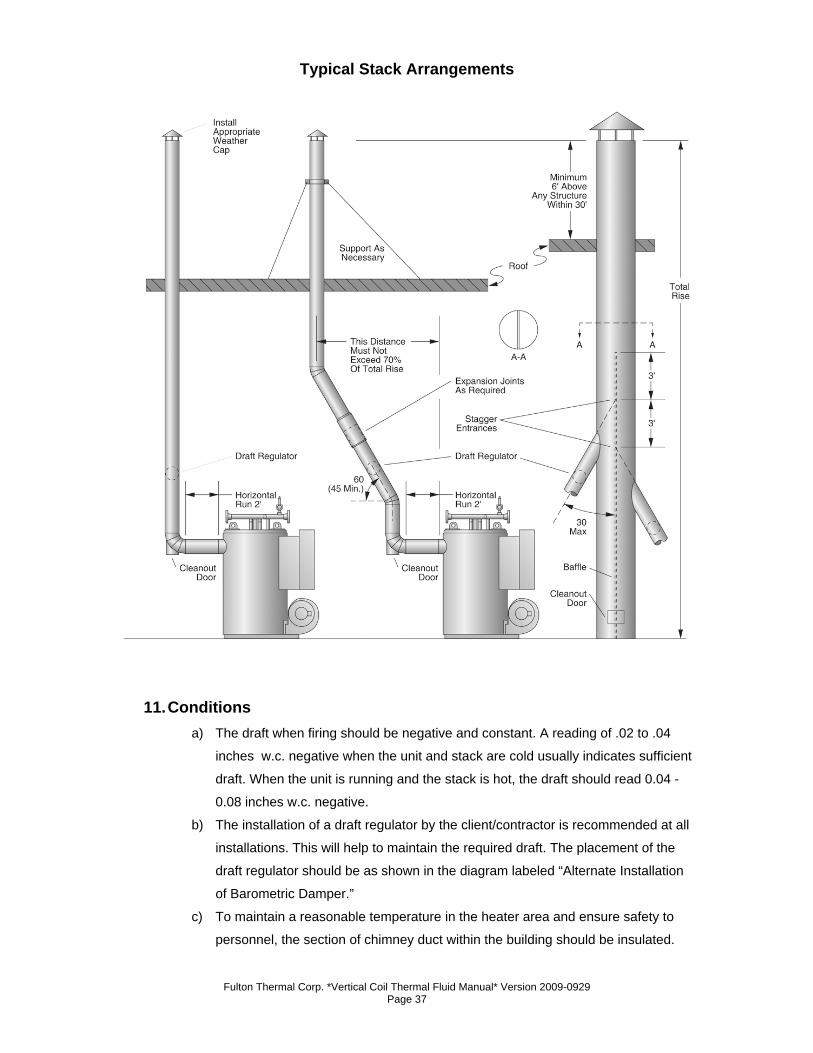
q) Stack & Flue Connections
1. An appropriately sized stack should be connected to the flue gas
outlet at the heater unit. The stack should be the same diameter
as the flue gas outlet for an FT-0080-C, and at least one size
larger for coil design models FT-0120-C and larger.
2. The stack should rise continuously to the connection of the
chimney and should contain no more than two bends, at 45°
angles or less.
3. There should be two feet of straight, horizontal flue before any
change in direction, fitting, or draft regulator. This is to prevent
potential pilot or main flame failures due to back pressure
buildup during ignition.
4. Any alternative stack arrangement must supply negative .02 to
04” water column.
5. The run in the total distance of stack ducting, as measured in a
straight line from the outlet of the heater to the outlet of the
stack, should not exceed 70% of the rise. See diagram below.
Note
With the exception of the duct run previously described, horizontal sections of ducting must be avoided and should not exceed four feet total.
6. The stack, chimney, and any components associated with the
stack, such as heat reclaimers or assist fans, must be
constructed from material that is rated for a 1200°F operating
temperature.
7. Adequate provision must be made for the support of the weight
of the chimney and stack to avoid having a load imparted to the
outlet connection of the heater.
Fulton Thermal Corp. *Vertical Coil Thermal Fluid Manual* Version 2009-0929 Page 37
Typical Stack Arrangements
11. Conditions a) The draft when firing should be negative and constant. A reading of .02 to .04
inches w.c. negative when the unit and stack are cold usually indicates sufficient
draft. When the unit is running and the stack is hot, the draft should read 0.04 -
0.08 inches w.c. negative.
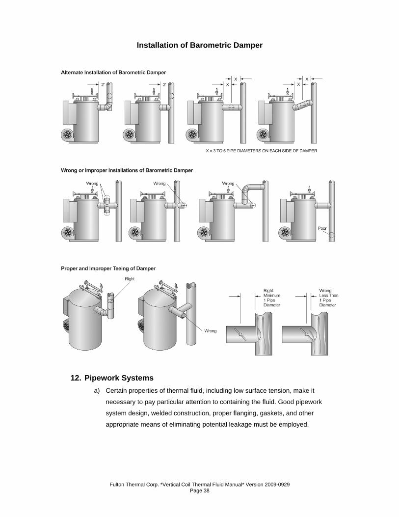
b) The installation of a draft regulator by the client/contractor is recommended at all
installations. This will help to maintain the required draft. The placement of the
draft regulator should be as shown in the diagram labeled “Alternate Installation
of Barometric Damper.”
c) To maintain a reasonable temperature in the heater area and ensure safety to
personnel, the section of chimney duct within the building should be insulated.
Fulton Thermal Corp. *Vertical Coil Thermal Fluid Manual* Version 2009-0929 Page 38
Installation of Barometric Damper
12. Pipework Systems a) Certain properties of thermal fluid, including low surface tension, make it
necessary to pay particular attention to containing the fluid. Good pipework
system design, welded construction, proper flanging, gaskets, and other
appropriate means of eliminating potential leakage must be employed.
Fulton Thermal Corp. *Vertical Coil Thermal Fluid Manual* Version 2009-0929 Page 39
13. General a) All components exposed to thermal fluid flow, including pipe, valves, and
screens, must not be made out of copper, copper alloys, aluminum, or cast iron.
Cast iron is porous to thermal fluids, and copper and aluminum act as catalysts in
the degradation of some thermal fluids. Carbon or stainless steel, or ductile iron,
are recommended.
b) For standard applications, all components must be rated to 650°F unless
otherwise stipulated.
c) All pipework, valves, and user equipment must be suited to the maximum
operating pressure of the heater. The maximum pressure stamped on the heater
nameplate is typically 150 psig (690 kPa).
d) If an isolating valve is completely closed, the pressure in the system will rise to
the deadhead pressure of the pump. Suitably sized pipe will enable the system to
withstand the total head generated by the circulating pump, should this occur. In
applications where it is desirable to design to pressures lower than 100 psig, an
alternative safeguard is to install appropriately sized safety valves.
e) Where secondary circulating pumps are installed, the system must be suitable for
the aggregate head, against a closed valve, of both pumps.
f) During construction of the installation, ensure that no dirt, water, or residue from
welding is left in the system.
14. Equipment a) Heaters that are skid mounted with pumps and tanks are equipped with a y-
strainer, a flex connector and a valve in the inlet run between the pump and the
combination tank. Piping between the discharge of the pump and the inlet of the
heater will include a flex connector and a valve.
15. Piping a) All pipework should be constructed from seamless mild steel pipe, conforming to
ASME SA 106B or SA 53B, Schedule 40 or equal.
b) Expansion joints or properly designed and sited loops should be provided to
accommodate thermal expansion. Thermal expansion should be calculated using
the maximum possible utilization fluid temperature, regardless of whether the
pipe considered is in the feed or return circuit. Steel pipe will expand
approximately 1 “ per 100’ over a 100° F. temperature rise (1 mm. per meter over
100°C. rise).
Fulton Thermal Corp. *Vertical Coil Thermal Fluid Manual* Version 2009-0929 Page 40
c) Supports and anchors must be provided for all pipes where necessary to prevent
undue stresses from being placed on items of equipment, including pumps,
valves, and the heater. Supports and anchors which will not interfere with thermal
expansion should be chosen.
d) All pipe joints should be of either welded or flanged construction. Screwed joints
must be avoided where possible. In no instance should screwed joints be used in
the flow circuit.
e) All flanges should be welded to the pipe and not screwed. Flanges should be
150# or 300# raised face flanges, SA105.
f) Gasketing material suitable for use with thermal fluids at high temperatures
should be used to make all flanged joints. Flexible graphite gaskets are suited for
most thermal fluids. Recommended gasket thickness is 1/10 - 1/8 inch.
g) Ensure that all bolts are tightened evenly and to the torque recommended values
provided by the gasket manufacturer.
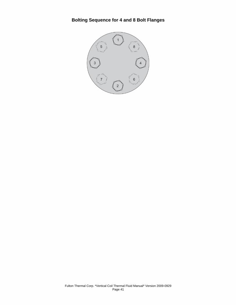
16. Gasket Installation Instructions a) Lubricate nuts, bolts and washers with a graphite/oil mixture.
b) Assure that the flange surfaces are clean and free from damage.
c) Center gasket properly over flange. In retrofit, use pry bar to spread flange apart
enough that the gasket will not be damaged when sliding in place.
d) Install all flange nuts and bolts.
e) Hand tighten.
f) Utilizing a torque wrench, tighten all bolts to 20% final torque specification
following a “star” pattern. (This means do not tighten bolts in order as a clock.
This will result in a poor seat between 12 o’clock and 1 o’clock.)
g) Tighten all bolts to 40% final torque specification following a “star” pattern.
h) Tighten all bolts to 60% final torque specification following a “star” pattern.
i) Tighten all bolts to 80% final torque specification following a “star” pattern.
j) Tighten all bolts to 100% final torque specification following a “star” pattern.
k) Following a sequential pattern, ensure that all bolts are tightened to 100% final
torque specification.
l) It is important that all bolts are checked and re-torqued after flanges have been
heated and cooled down for the first time.
Fulton Thermal Corp. *Vertical Coil Thermal Fluid Manual* Version 2009-0929 Page 41
Bolting Sequence for 4 and 8 Bolt Flanges
Fulton Thermal Corp. *Vertical Coil Thermal Fluid Manual* Version 2009-0929 Page 42
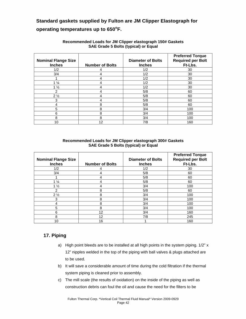
Standard gaskets supplied by Fulton are JM Clipper Elastograph for operating temperatures up to 650oF.
Recommended Loads for JM Clipper elastograph 150# Gaskets SAE Grade 5 Bolts (typical) or Equal
Nominal Flange Size Inches Number of Bolts
Diameter of Bolts Inches
Preferred Torque Required per Bolt
Ft-Lbs. 1/2 4 1/2 30 3/4 4 1/2 30 1 4 1/2 30
1 ¼ 4 1/2 30 1 ½ 4 1/2 30
2 4 5/8 60 2 ½ 4 5/8 60
3 4 5/8 60 4 8 5/8 60 5 8 3/4 100 6 8 3/4 100 8 8 3/4 100
10 12 7/8 160
Recommended Loads for JM Clipper elastograph 300# Gaskets SAE Grade 5 Bolts (typical) or Equal
Nominal Flange Size Inches Number of Bolts
Diameter of Bolts Inches
Preferred Torque Required per Bolt
Ft-Lbs. 1/2 4 1/2 30 3/4 4 5/8 60 1 4 5/8 60
1 ¼ 4 5/8 60 1 ½ 4 3/4 100
2 8 5/8 60 2 ½ 8 3/4 100
3 8 3/4 100 4 8 3/4 100 5 8 3/4 100 6 12 3/4 160 8 12 7/8 245
10 16 1 160
17. Piping
a) High point bleeds are to be installed at all high points in the system piping. 1/2” x
12” nipples welded in the top of the piping with ball valves & plugs attached are
to be used.
b) It will save a considerable amount of time during the cold filtration if the thermal
system piping is cleaned prior to assembly.
c) The mill scale (the results of oxidation) on the inside of the piping as well as
construction debris can foul the oil and cause the need for the filters to be
Fulton Thermal Corp. *Vertical Coil Thermal Fluid Manual* Version 2009-0929 Page 43
cleaned more than need be. This can range from simply using a rag to ordering
pickled pipe. (“Pickling” is a process where the piping is first soaked in an acid
bath, then soaked in a neutralizing bath, then given a protective oil coating.)
d) All pipes should be installed with a pitch to facilitate draining and venting.
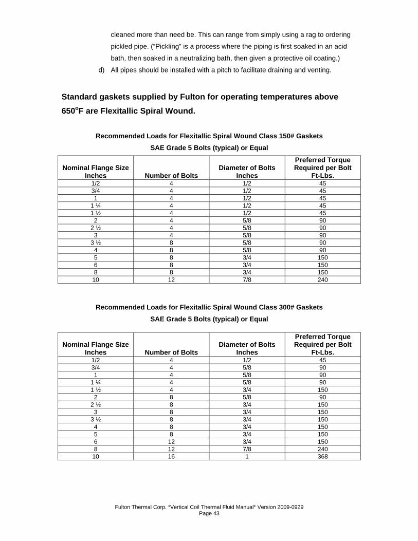
Standard gaskets supplied by Fulton for operating temperatures above 650oF are Flexitallic Spiral Wound.
Recommended Loads for Flexitallic Spiral Wound Class 150# Gaskets SAE Grade 5 Bolts (typical) or Equal
Nominal Flange Size Inches Number of Bolts
Diameter of Bolts Inches
Preferred Torque Required per Bolt
Ft-Lbs. 1/2 4 1/2 45 3/4 4 1/2 45 1 4 1/2 45
1 ¼ 4 1/2 45 1 ½ 4 1/2 45
2 4 5/8 90 2 ½ 4 5/8 90
3 4 5/8 90 3 ½ 8 5/8 90
4 8 5/8 90 5 8 3/4 150 6 8 3/4 150 8 8 3/4 150
10 12 7/8 240
Recommended Loads for Flexitallic Spiral Wound Class 300# Gaskets
SAE Grade 5 Bolts (typical) or Equal
Nominal Flange Size Inches Number of Bolts
Diameter of Bolts Inches
Preferred Torque Required per Bolt
Ft-Lbs. 1/2 4 1/2 45 3/4 4 5/8 90 1 4 5/8 90
1 ¼ 4 5/8 90 1 ½ 4 3/4 150
2 8 5/8 90 2 ½ 8 3/4 150
3 8 3/4 150 3 ½ 8 3/4 150
4 8 3/4 150 5 8 3/4 150 6 12 3/4 150 8 12 7/8 240
10 16 1 368
Fulton Thermal Corp. *Vertical Coil Thermal Fluid Manual* Version 2009-0929 Page 44
18. System Connections
a) If screwed connections have to be made, e.g. to items of control equipment, then
a thread sealant suitable for use with fluids at elevated temperature must be
used. Teflon tape, standard pipe dope, or hemp and paste are not acceptable.
b) Screw threads must be carefully and accurately cut. If possible, new tools should
be used. Threaded connections larger than 1” are not to be used. It is
recommended that GR5 or better tensile steel bolts be used for all flanged joints.
Note
The system pump is not to be used to fill the system.
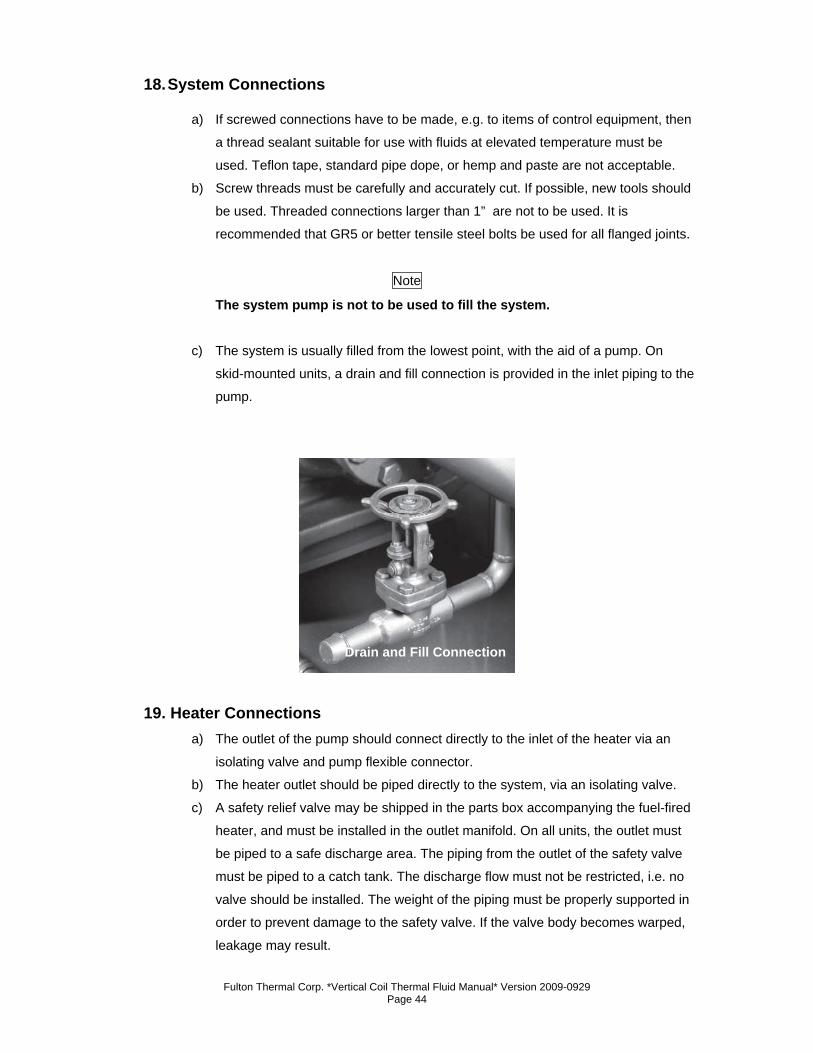
c) The system is usually filled from the lowest point, with the aid of a pump. On
skid-mounted units, a drain and fill connection is provided in the inlet piping to the
pump.
19. Heater Connections a) The outlet of the pump should connect directly to the inlet of the heater via an
isolating valve and pump flexible connector.
b) The heater outlet should be piped directly to the system, via an isolating valve.
c) A safety relief valve may be shipped in the parts box accompanying the fuel-fired
heater, and must be installed in the outlet manifold. On all units, the outlet must
be piped to a safe discharge area. The piping from the outlet of the safety valve
must be piped to a catch tank. The discharge flow must not be restricted, i.e. no
valve should be installed. The weight of the piping must be properly supported in
order to prevent damage to the safety valve. If the valve body becomes warped,
leakage may result.
Drain and Fill Connection
Fulton Thermal Corp. *Vertical Coil Thermal Fluid Manual* Version 2009-0929 Page 45
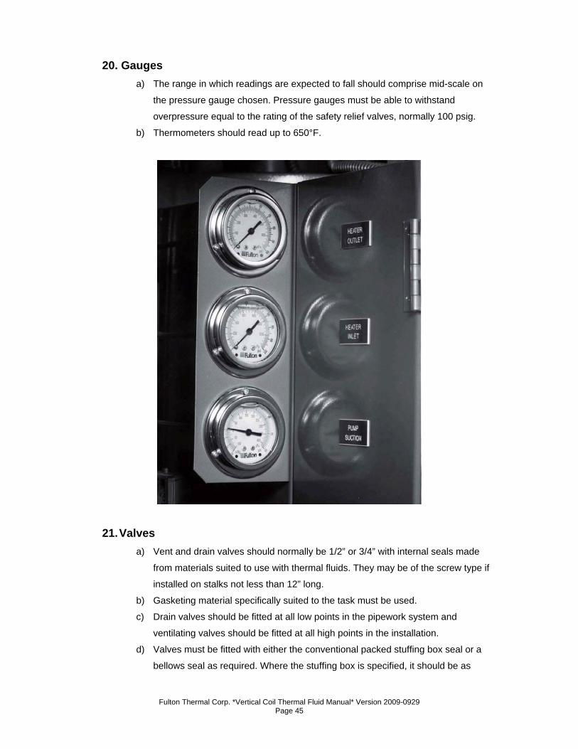
20. Gauges a) The range in which readings are expected to fall should comprise mid-scale on
the pressure gauge chosen. Pressure gauges must be able to withstand
overpressure equal to the rating of the safety relief valves, normally 100 psig.
b) Thermometers should read up to 650°F.
21. Valves a) Vent and drain valves should normally be 1/2” or 3/4” with internal seals made
from materials suited to use with thermal fluids. They may be of the screw type if
installed on stalks not less than 12” long.
b) Gasketing material specifically suited to the task must be used.
c) Drain valves should be fitted at all low points in the pipework system and
ventilating valves should be fitted at all high points in the installation.
d) Valves must be fitted with either the conventional packed stuffing box seal or a
bellows seal as required. Where the stuffing box is specified, it should be as
Fulton Thermal Corp. *Vertical Coil Thermal Fluid Manual* Version 2009-0929 Page 46
deep as possible and packed with Grafoil packing or equal. The valves should
have a backseating to allow re-packing without draining the system. In all units, a
“Y” type strainer should be installed in the fluid return line, between the deaerator
tank and the circulating pump.
e) As previously stated, this strainer is provided on all skid-mounted units. Valves
must be provided (unless the heater has been skid-mounted with the tank) so
that the strainer can be isolated for cleaning of the element. The strainer element
should be 60 mesh and must remain in place during normal operation of the
system.
f) The pump suction pressure should be checked periodically, under similar
operating conditions. A vacuum reading on the suction gauge indicates that the
screen must be cleaned. For isolating purposes, globe, wedge, gate, ball, or
other shut-off valves should be used. When there is a likelihood that some
manual balancing will be required, a ball or globe valve should be used.
g) Manual control and isolating valves should be the flanged or weld type,
manufactured from cast or forged steel or ductile iron, with internals and gland
seals made from materials suitable for use with high temperature fluids.
h) When ordering valves, the maximum possible service temperature and type of
fluid must be indicated on the order.
i) A partial list of manufacturers known to market valves of acceptable quality
follows:
1. Jenkins Brothers
2. Lunkenheimer Company
3. Nibco Incorporated
4. Stockham Valves and Fittings Company
5. Velan
6. Vogt Machine Company
7. Worcester Valve Company
j) Automatic Fluid Control Valves
1. Because of the widely varied processes Fulton Thermal Fluid
Heaters are used in, it is not possible to set down specific rules
for the selection of automatic fluid control valves. Generally,
these valves must satisfy the materials and construction
requirements described above.
2. The type of operation and design of porting are governed by the
degree of control required as well as the particular application.
Fulton Thermal Corp. *Vertical Coil Thermal Fluid Manual* Version 2009-0929 Page 47
k) Bypass Valves
1. When process flow requirements do not match heater flow
requirements, a by-pass valve must be installed.
2. If the process flow will vary with the system load, a suitable
bypass system can be recommended by Fulton Thermal
Corporation.
22. Testing a) Upon completion of the installation, a pneumatic test not exceeding 15 psig
should be conducted. Soap tests should be made at all welds and joints to
ensure that the system is free from leaks.
b) Under no circumstances should the system be filled with water. Make sure that
the air supply is as free from moisture as possible.
c) The most satisfactory method of testing is to introduce bottled nitrogen through a
pressure control valve. Check pressure ratings on all the equipment in the
system to make sure that it is capable of withstanding the pressure involved.
d) The time needed to be spent during boilout directly corresponds to the amount of
moisture in the system. Boilout can take anywhere from two to three days to
complete. Pressure testing on the system should be done by means of an inert
gas, such as nitrogen, or by an air compressor producing dry air (air with a
dewpoint of 50o F or less). Never perform a hydrostatic test on the system.
23. Insulation a) After the appropriate system tests have been satisfactorily completed, all hot
pipework, including manifolds on the heater, must be adequately insulated with
material suited to the temperature and application to prevent both heat loss and
personnel injury.
Caution
For reasons of safety, the hot exhaust gas duct and chimney must be insulated or shielded within the locality of the heater.
b) The deaerator section of the combination tank must be insulated. The expansion
section of the combination tank must not be insulated, nor should the thermal
buffer section.
c) On units operated with inert gas blankets above the fluid in the expansion tank,
the entire combination tank, including the expansion and thermal buffer sections,
may be insulated, but is not necessary.
Fulton Thermal Corp. *Vertical Coil Thermal Fluid Manual* Version 2009-0929 Page 48
d) It is recommended that for inspection and maintenance, pumps, flanges, valves,
and fittings be left un-insulated but suitably shielded for safety.
e) Hot oil pipe insulation should be a minimum of 2” thick, high temperature,
laminated, foamglass cellular glass insulation as manufactured by Pittsburgh
Corning Corporation, or equal.
24. Thermal Fluids Thermal Fluids at Elevated Temperatures
a) Plant engineers must be familiar with the nature of potential hazards when
working with thermal fluids at operating temperatures.
b) Unlike steam or high-pressure water systems, thermal fluid attains extremely
high temperatures without a corresponding increase in pressure. While this lack
of high pressure in the system yields many advantages, a false sense of security
should not be allowed to develop on account of this alone.
c) Certain types of thermal fluid may have operating temperatures reaching 650°F
(345°C) and above, so all exposed pipework is hazardous and should be
insulated, as indicated in the preceding sections.
d) Flanged joints must be checked for tightness during and after the first warming
up of the system. After these checks, exposed hot flanges, pumps, valves and
fittings should be fitted with some sort of shield.
e) It is important to remember that there is pressure generated in the system by the
circulating pump. Great care should be exercised when opening any drain or vent
valves in the system.
f) This is especially important during commissioning, when any air trapped in the
system is vented at high points, and when water, which will flash into steam, is
either expelled from the deaerator vent or drained off at low points.
Caution
During operation, any leaks are usually detected by a small amount of vapor. Leaks should be attended to as soon as possible because under certain circumstances, such as saturated insulation, thermal fluid can ignite when exposed to air and heat.
g) If a fire does occur, extinguish using CO2, foam or dry chemical. DO NOT USE
WATER.
h) Selecting a Thermal Fluid
1. The selection of the thermal fluid most suited to your application
is very important. Factors to be considered include efficiency,
thermal stability, adaptability to various systems, and physical
Fulton Thermal Corp. *Vertical Coil Thermal Fluid Manual* Version 2009-0929 Page 49
properties, including vapor pressure, freezing point, and flash
and fire points.
2. Heat transfer fluids of both mineral and synthetic origin have
been specially developed to give thermal stability over a very
wide range of temperature. A wide variety of thermal fluids have
been used successfully in Fulton Thermal Fluid Heater systems,
however, your final selection should be made in conjunction with
Fulton Thermal Corporation or the fluid manufacturer.
3. The Fulton coil design heater is a fired heat exchanger and the
safe control and monitoring of the thermal fluid temperature is of
paramount importance.
4. The safe maximum bulk temperature of the fluid must be strictly
adhered to. The safe maximum temperature of the fluid varies,
but a typical maximum for many types of mineral oil based fluids
is 600°F (320°C).
5. Special care must be taken when consulting fluid manufacturers’
literature, as maximum fluid temperatures quoted are the actual
limit to which any of the fluids may be subjected. It is important to
remember that in any fired heater there exists a “film
temperature” which is higher than the temperature of the “bulk”
of the fluid.
6. It is the BULK fluid temperature and NOT the FILM temperature
that is indicated by the instruments.
7. As a general guide, the following list of fluids that have given
satisfactory service over many years is provided.
8. This is by no means a complete list. Any fluid specifically
designed for heat transfer use may be considered; multipurpose
oils are not acceptable. a. AMOCO Transfer Oil 4199
b. CHEVRON Teknifax
c. DOW Dowtherm A or G
d. EXXON Caloria HT 43
e. MOBIL Mobiltherm 603 or 605
f. MONSANTO Therminol
g. MULTITHERM PG1, IG4, IG1
h. PARATHERM Paratherm NF or HE
i. PETROCANADA CalFlo, AF, Purity FG, CalFlo LT
j. SHELL Thermia 23
k. TEXACO Texatherm
Fulton Thermal Corp. *Vertical Coil Thermal Fluid Manual* Version 2009-0929 Page 50
9. Any fluid specifically designed for heat transfer use must also
exhibit these characteristics:
a. Be a stable and homogenous liquid to a temperature of
at least 100°F over and above the maximum intended
temperature of utilization, compatible with metals used in
the installation, and tolerating contact with atmospheric
air.
b. The absence of any solid matter in suspension.
c. Non-toxic in the case of leakage.
d. Sufficient lubricity, i.e. not likely to cause seizure.
10. The thermal fluid manufacturer must guarantee the
characteristics of the product, and verify that the fluid bulk
temperature limitation exceeds the expected operating
temperature.
11. After a fluid is selected, refer to the manufacturer’s
recommendations, published in compliance with OSHA.
12. If the fluid expansion volume from 50o F to 600°F exceeds 20%
of the initial fluid volume, consult Fulton Thermal Corporation.
Note
Fulton Thermal Corporation cannot be held responsible in the case of accident or damage resulting from the use of inadequate fluid.
i) Routine Analysis of Heat Transfer Fluid
1. Nearly all leading manufacturers of heat transfer fluids provide
an after sales service to monitor the condition of the fluid in
operation and make recommendations when replacement
becomes necessary.
2. Each fluid manufacturer has procedures for regular testing and
analysis of the fluid. These usually allow for a sample to be taken
and analyzed at least once a year, although actual frequency will
depend on operating temperature, number of hours operated
weekly, and the results of tests made during the first weeks of
system operation.
3. Fulton Thermal Corporation recommends that the thermal fluid in
your system be analyzed within the first two months after start-
up.
Fulton Thermal Corp. *Vertical Coil Thermal Fluid Manual* Version 2009-0929 Page 51
4. During the first few months of operation, sampling may be
carried out at frequent intervals to confirm that system
performance has been predicted correctly.
5. If the supplier of your thermal fluid does not contact you within
four weeks of commissioning, contact the supplier and make
certain that the “fill” is registered for routine analysis.
j) Thermal Fluid Breakdown
1. The possibilities of thermal fluid breakdown are very slim in a
typical closed loop thermal fluid system. Fulton’s D/A tank
creates a “cold seal” of fluid that is slightly above ambient
temperature. This prevents oxidation that will happen when high
temperature fluid contacts air.
2. This will also occur when hot thermal fluid contacts air at a leak
in the system piping. Oxidized thermal fluid becomes acidic and
will damage the thermal fluid system. Thermal fluid breakdown
can occur in sections of piping where there is a low flow
Fulton Thermal Corp. *Vertical Coil Thermal Fluid Manual* Version 2009-0929 Page 52
condition. A low flow rate through the heater will result in high
film temperatures leading to breakdown of the thermal fluid.
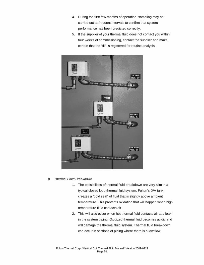
3. Multiple pressure switches and a differential pressure switch are
used to prevent this condition from occurring. These safeties
must not be bypassed at any time.
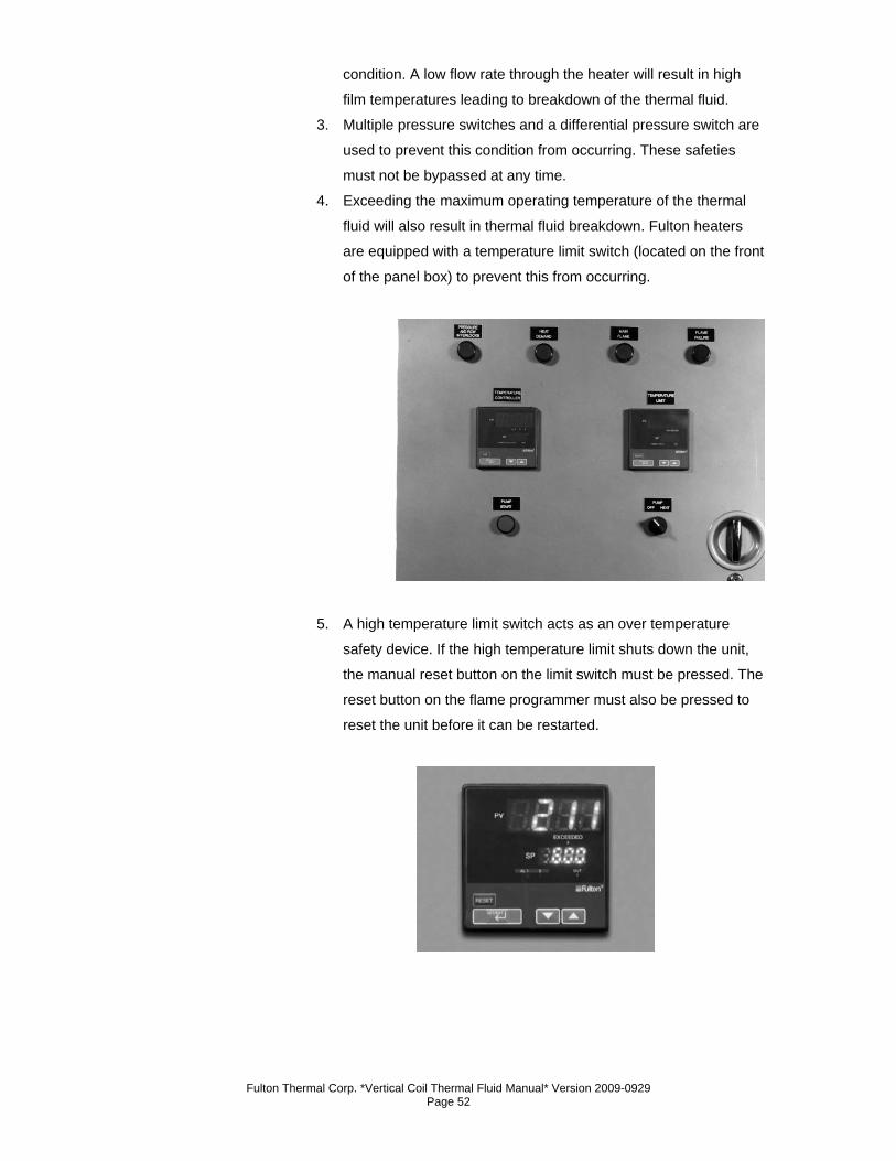
4. Exceeding the maximum operating temperature of the thermal
fluid will also result in thermal fluid breakdown. Fulton heaters
are equipped with a temperature limit switch (located on the front
of the panel box) to prevent this from occurring.
5. A high temperature limit switch acts as an over temperature
safety device. If the high temperature limit shuts down the unit,
the manual reset button on the limit switch must be pressed. The
reset button on the flame programmer must also be pressed to
reset the unit before it can be restarted.

Fulton Thermal Corp. *Vertical Coil Thermal Fluid Manual* Version 2009-0929 Page 53
Section 3

Fulton Thermal Corp. *Vertical Coil Thermal Fluid Manual* Version 2009-0929 Page 54
Fulton Thermal Corp. *Vertical Coil Thermal Fluid Manual* Version 2009-0929 Page 55
Section 3 – Operation
1. Start-Up Preparation & Installation Review a) Check with local authorities where approval for start-up is required. In some
localities, final inspection of services may be required.
b) Review the installation section of this manual carefully. Confirm accordance with
installation guidelines, including:
1. In general, ensure that the heater area is in conformance with
established heater room requirements. Review national and local
codes.
2. Preparation a) Check for total absence of water in pipework and fluid. To help the system, open
all drains; blow air nitrogen if available into a high point bleed through a pressure
regulating valve.
Note
Unless specially filtered, compressed air will introduce moisture into the system. Dry air or Nitrogen is recommended.
b) Make sure that there are no obstructions left in the thermal fluid circuit from
pressure leak testing such as blanking plates in flanged joints.
c) Check that pipework is free to expand naturally when hot. Open all valves to user
circuits including air bleed valves at high points and drains at low points in the
piping system, and the liquid level test connections in the expansion section of
the combination tank.
3. Filling the System a) The viscosity of thermal fluid is generally very high (500 cS) at ambient
temperature. Below 50°F (10°C) some fluids become very thick. Fluid should be
in a pumpable liquid form prior to filling the system.
b) Filling must be carried out from the lowest point in the system in order to prevent
air pockets from forming.
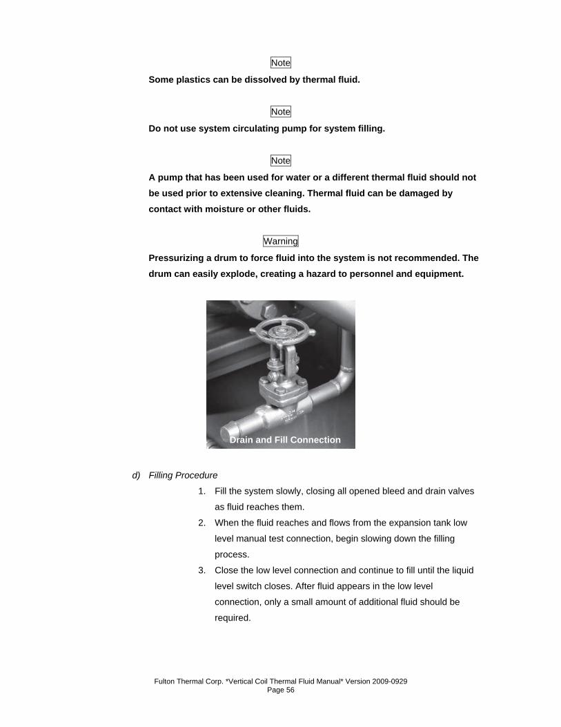
c) A drain and fill point (generally a 3/4” threaded coupling) is provided on the inlet
to the pump suction on skid-mounted units. Typically a portable, high velocity
pump, such as the type used for chemical transfer, is appropriate for filling the
system. Where only one or two drums of fluid are required, a handheld pump
may be practical.
Fulton Thermal Corp. *Vertical Coil Thermal Fluid Manual* Version 2009-0929 Page 56
Note
Some plastics can be dissolved by thermal fluid.
Note
Do not use system circulating pump for system filling.
Note
A pump that has been used for water or a different thermal fluid should not be used prior to extensive cleaning. Thermal fluid can be damaged by contact with moisture or other fluids.
Warning
Pressurizing a drum to force fluid into the system is not recommended. The drum can easily explode, creating a hazard to personnel and equipment.
d) Filling Procedure
1. Fill the system slowly, closing all opened bleed and drain valves
as fluid reaches them.
2. When the fluid reaches and flows from the expansion tank low
level manual test connection, begin slowing down the filling
process.
3. Close the low level connection and continue to fill until the liquid
level switch closes. After fluid appears in the low level
connection, only a small amount of additional fluid should be
required.
Drain and Fill Connection
Fulton Thermal Corp. *Vertical Coil Thermal Fluid Manual* Version 2009-0929 Page 57
4. If fluid is observed coming from the expansion section high level
manual test connection, drain fluid from the tank until the level is
between the liquid level switch and the high level connection.
5. Filling is complete when the fluid has reached the lowest level in
the expansion tank required to actuate the liquid level switch.
Check to see that the liquid level switch operates freely. To
confirm operation of the liquid level switch, manually trip the
liquid level switch. Unit should shut down; pump will stop.
4. For Systems Equipped with Inert Blankets a) Follow the instructions listed under “Filling The System”.
b) Pay close attention to notes and warnings.
c) Inspect the system to be sure all valves are open and all drains are closed.
d) Open all high point air vents.
e) Do not pressurize the system with nitrogen at this point.
f) Inspect the liquid level switch and be sure the switch is functioning properly.
g) Begin filling the system.
h) Fill the system until the liquid level switch indicates there is oil in the expansion
tank.
i) Pressurize the system slightly with nitrogen. Leave the high point vent
connections open, as the nitrogen should be isolated from the vents by the oil in
the system. The pressure required in the system at this point is only 2-3 psi. If too
much pressure is applied, the nitrogen will bubble through the oil and vent to
atmosphere. If this happens, reduce the pressure.
j) Continue filling the system. If liquid level switch is made, be sure to observe the
high point vents as oil is now entering the elevated portion of the pipe work. As
oil reaches the vent, close it. After all vents have been closed, and you believe
the system to be full, stop filling. Start the circulating pump as described under
“Cold Circulation.” Leave the fill equipment connected as cleaning the strainer
may create the need for more oil in the system.
k) The final nitrogen pressure is determined by measuring the difference between
the D.A. Tank inlet and the highest point in the system. Divide that number by
2.31 (this will indicate the nitrogen pressure the system should be set for).
Adjustment can be made via the regulator mounted on top of the D.A. tank.
Note
Tanks are non-code as a standard. Non-code tanks cannot be pressurized over 15psig. Tanks built to ASME code Section VIII Div 1 are available upon request.
Fulton Thermal Corp. *Vertical Coil Thermal Fluid Manual* Version 2009-0929 Page 58
5. Circulating Pump a) Read manufacturer’s instruction manual thoroughly. If the pump is supplied by
Fulton Thermal Corporation, manufacturer’s literature is included in this manual.
Note
Do not run the pump before filling it with fluid.
b) The pump should never be run without fluid in the casing. For pumps equipped
with mechanical or air-cooled seals, air must be bled out of the stuffing box area
to ensure that thermal fluid has lubricated all seal and bearing areas. Operation
of the pump even a short time without bleeding first will damage the pump.
c) Also use the thermal fluid as a barrier fluid. Remove the 3/8” plug at the barrier
fluid fill port. Fill the cavity with thermal fluid until it comes out of the overflow
tube. Replace the 3/8” plug.
d) Mechanical/Air Cooled Seal
1. Open the air bleed connection located directly over the pump
shaft. Replace plug when a steady stream of thermal fluid, free
of entrained air, flows from the port.
2. If flow has not started after two to five minutes, remove the
coupling guard and rotate the pump shaft by hand in the proper
direction. This should help move the cold viscous fluid through
close tolerance seal areas. Replace plug when flow is steady.
3. If this fails to induce flow, introduce fluid through the bleed port
and rotate the shaft by hand to work the fluid around the seal
area. Continue to add fluid and rotate the shaft until no more fluid
can be added.
4. Replace the plug and run pump for five to ten seconds. Stop the
pump, remove the plug and wait for flow to start. If after two
minutes flow has not started, add more fluid as described above
and run the pump for five minutes.
5. Constantly check the bearing area (located immediately behind
the casing) for overheating. Remove the plug and check for flow.
6. If flow has not started at this point, the fluid may be too viscous
to move through the seal area. Start the system normally by
selecting heat on the control panel, and raise the temperature
50°F. Continue to raise the system temperature by 50°F
increments. Keep checking the pump until flow starts.
Fulton Thermal Corp. *Vertical Coil Thermal Fluid Manual* Version 2009-0929 Page 59
Caution
1. Use extreme caution opening plug when system temperature is elevated.
2. Wear eye and hand protection. 3. Back the plug out slowly to the last two or three threads. Allow any
pressure under plug to bleed slowly to prevent a spray of hot oil.
7. The pump should not be subjected to thermal or pressure shock.
The thermal fluid should, therefore, be allowed to flow into the
casing slowly.
8. Check field work and make sure that all connections have been
made in the proper places. Check electrical connections to the
motor.
9. Rotate the pump shaft by hand to be sure there is no binding or
rubbing within the pump or driver. Correct any problems
immediately.
10. Check to see that pump is properly aligned while cold.
11. The pump is properly aligned before it leaves the factory.
Because the system expands in operation, the pump must be
realigned when the system is at operating temperature.
12. The coupling alignment of the pump and driver must be carefully
checked for angular and axial alignment. Check pump
manufacturers instructions for these specifications. The use of a
dial indicator to check the axial and angular alignment is
recommended.
13. Realign at operating temperature, if necessary.
14. Make sure that the pump is properly greased or oiled.
e) Pumps with Packed Seals
1. Make sure that the gland is finger tight before filling the system.
6. Initial Start-Up a) These instructions are for use when the unit is being started up for the first time,
or after prolonged shutdown. They are to be used in conjunction with the specific
procedure information in titled section, “Routine Operation.”
Fulton Thermal Corp. *Vertical Coil Thermal Fluid Manual* Version 2009-0929 Page 60
7. Start-Up Service a) If start-up service has been included in the order, the factory should be contacted
after the installation has been successfully completed and approved by the
client’s representative or engineers. Where possible, contact the factory at least
one week before a Fulton service engineer is required on site.
b) All procedures covered in Operating Instruction sections “Start-Up Preparation”
and Filling the System,” including installation review, air testing of piping, pump
alignment, and filling the system must be completed before the service person’s
arrival.
c) Depending on the size of the system and the amount of service time contracted
for, start-up service includes firing the heater, boiling out the system, checking,
verifying and adjusting all safety settings.
d) Careful preparation can expedite the commissioning of your heater. Most delays
can be avoided by following the instructions in this manual. Failure to complete
required procedures properly can result in the need for further service time, at
extra cost to the customer.
e) Service people will not commence start-up if there are obvious system
deficiencies. However, start-up service in no way constitutes a system design
check or approval of the installation.
f) In addition to commissioning the heater, the service person will also familiarize
heater room personnel with the operation of all Fulton equipment. Personnel
must be qualified to understand the basic operation and function of controls.
8. Cold Circulation a) Turn on the main power switches.
b) Check for proper fluid level in the expansion section of tank.
c) A centrifugal pump cannot be operated with the discharge valve closed without
heating up dangerously.
d) The pump should be started with the suction valve full open and the discharge
valve open a slight amount.
e) Check pump rotation. Operating the pump in reverse rotation may cause
extensive damage.
f) Turn the three position switch located on the front of the panel box door to
“Pump”.
g) Jog the green pump motor starting button and observe the direction of rotation.
Rotation should be in the direction of the arrow shown on pump casing.
h) If the rotation direction is incorrect, turn the three position switch back to “Off”
immediately. Change the wiring connections and recheck.
i) Check for proper alignment. Realign, at temperature.
Fulton Thermal Corp. *Vertical Coil Thermal Fluid Manual* Version 2009-0929 Page 61
j) With the control switch set to “Pump” push and hold the pump start button, check
all manual resets on pressuretrols. The circulating pump will run, but the burner
will not fire.
k) If the pump stops when the button is released, check for proper flow in the
system, and review settings of high and low fluid pressure switches and
differential pressure switch. Check liquid level switch.
l) Check that all pressure gauge readings remain stable. Pressure exceeding 100
PSIG or identical readings at inlet and outlet gauges indicate a closed valve.
m) If an extremely high vacuum (i.e.15” Hg or more) is indicated on the compound
gauge, the valve between the circulating pump and the combination tank may
have been left closed. In this case, little or no pressure will be indicated by other
gauges.
9. Filtering the System a) Initially, readings on the compound gauge will indicate zero or slightly positive
pressure. During the first few moments of flow, this reading will go towards
vacuum, indicating that the strainer is becoming plugged.
b) Typically, a reading of 3” Hg or greater vacuum on the pump suction gauge
indicates that the strainer must be cleaned. The strainer screen should be back
flushed or pulled, cleaned and replaced.
c) Strainers should be cleaned by means of compressed air. A rag will merely force
the smaller particles into the mesh of the strainer. It is recommended to place a
lint free rag in the center of the strainer and blow air from the outside, trapping
the debris in the rag.
d) Allow the pump to run again for several minutes and repeat the filtering process
until pump suction pressure remains steady after cleaning. The amount of time
which must be allotted for filtering varies with the system.
e) When the system is initially brought up to temperature, additional pipe scale and
welding slag will loosen and enter the fluid stream. This will be trapped in the
strainer causing vacuum at the pump suction. This procedure must be followed
as necessary in the course of heater operation.
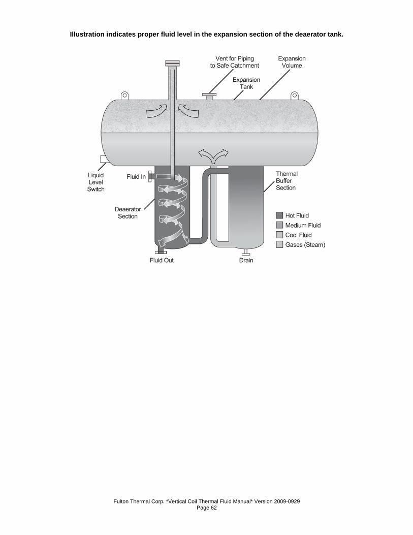
Fulton Thermal Corp. *Vertical Coil Thermal Fluid Manual* Version 2009-0929 Page 62
Illustration indicates proper fluid level in the expansion section of the deaerator tank.
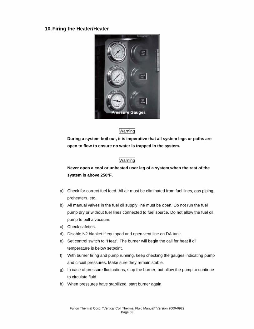
Fulton Thermal Corp. *Vertical Coil Thermal Fluid Manual* Version 2009-0929 Page 63
10. Firing the Heater/Heater
Warning
During a system boil out, it is imperative that all system legs or paths are open to flow to ensure no water is trapped in the system.
Warning
Never open a cool or unheated user leg of a system when the rest of the system is above 250°F.
a) Check for correct fuel feed. All air must be eliminated from fuel lines, gas piping,
preheaters, etc.
b) All manual valves in the fuel oil supply line must be open. Do not run the fuel
pump dry or without fuel lines connected to fuel source. Do not allow the fuel oil
pump to pull a vacuum.
c) Check safeties.
d) Disable N2 blanket if equipped and open vent line on DA tank.
e) Set control switch to “Heat”. The burner will begin the call for heat if oil
temperature is below setpoint.
f) With burner firing and pump running, keep checking the gauges indicating pump
and circuit pressures. Make sure they remain stable.
g) In case of pressure fluctuations, stop the burner, but allow the pump to continue
to circulate fluid.
h) When pressures have stabilized, start burner again.
Pressure Gauges
Fulton Thermal Corp. *Vertical Coil Thermal Fluid Manual* Version 2009-0929 Page 64
i) Continue in this manner up to the maximum operating temperature. Throughout
the initial warm-up, the expansion tank and its overflow pipe must be watched to
detect the formation of steam, indicating the presence of water. If this occurs,
burner should be shut down.
j) If steam is forcing thermal fluid out of the expansion tank vent, turn the heater off,
but leave the pump on. This is to circulate the hot fluid through the piping without
flushing the steam too quickly. Once steam and thermal fluid stop leaving the
expansion tank unit, the heater can be turned on. Increase the temperature very
slowly to prevent fluid from being forced out of the tank.
Note
Do not open drain or vent valves during operation.
Note
If excessive amounts of thermal fluid is vented from the system, additional thermal fluid may be required in the system.
Note
Flash steam may be generated at any point up to the operating temperature. Watch for gauge fluctuations.
k) Continue bringing unit up to temperature slowly, with a temperature rise not
exceeding 100°F (38°C) per hour. Do not exceed specified maximum outlet
temperature. In the absence of specific information, consult the factory before
proceeding.
l) Once up to temperature, check the fluid level in the expansion section by
opening the high level manual test connection. If a permanent flow of fluid results
when this valve is opened, and if all previous precautions have been followed,
the expansion tank is too small for the capacity of the fluid in the installation. A
larger tank must be installed.
m) After fifty hours of operation at operating temperature, check all flanges and
connections for tightness.
Note
Start-up technician should verify that all valves are opened prior to establishing flow and heat-up.
Fulton Thermal Corp. *Vertical Coil Thermal Fluid Manual* Version 2009-0929 Page 65
Note
If fluid or piping is added to the system the boil out procedure must be followed, as water has to be introduced into the system.
11. Procedure for First Shutdown a) The heater system should be shut down after no more than 24 hours of operation
at full operating temperature. At this time, the following maintenance items will
need to be completed to meet warranty conditions.
b) While pump is still at operating temperature, align circulating pump(s) to pump
manufacturer’s specifications. This should be done by means of a dial indicator.
c) Isolate Y-strainer(s) in system and clean regardless of pump suction pressure.
Make sure that the temperature is low enough to handle safely or provision has
been made to handle materials at high temperature. Generally, temperatures
below 150°F are acceptable to perform operation with regular work gloves.
d) With piping system cooled to ambient temperature, torque all bolts on skid and
throughout system to gasket manufacturer’s specifications using proper flange
torquing practices such as incremental torque increases, star pattern, etc. Refer
to Installation Section.
e) Visually inspect all thread fittings and valve packings. Repair leaks and tighten
valve packings to the point of stopping leak.
f) Upon putting unit back into operation, check all gauge readings and compare to
values given to you by the start-up technician. Note any discrepancies and
contact Fulton.
12. Required Pressure Drop Across the Heater a) The thermal fluid pressure drop across your heater is critical. This should be
recorded at the completion of start-up. The pressure drop value is obtained by
subtracting the heater outlet pressure from the heater inlet pressure when the
thermal fluid is at normal operating temperature.
b) At the recommended standard flow rates, and .7 sp gr, the pressure drop across
the heater should be as shown in the chart at the top right.
c) In the event of an abnormal reading, contact Fulton Service immediately. Failure
to take immediate action in the event of reduced fluid flow may result in rapid and
serious degradation of the fluid, with possible damage to the heater.
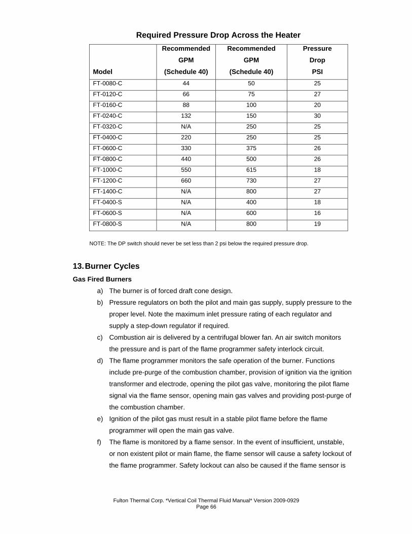
Fulton Thermal Corp. *Vertical Coil Thermal Fluid Manual* Version 2009-0929 Page 66
Required Pressure Drop Across the Heater
Model
Recommended GPM
(Schedule 40)
Recommended GPM
(Schedule 40)
Pressure Drop PSI
FT-0080-C 44 50 25
FT-0120-C 66 75 27
FT-0160-C 88 100 20
FT-0240-C 132 150 30
FT-0320-C N/A 250 25
FT-0400-C 220 250 25
FT-0600-C 330 375 26
FT-0800-C 440 500 26
FT-1000-C 550 615 18
FT-1200-C 660 730 27
FT-1400-C N/A 800 27
FT-0400-S N/A 400 18
FT-0600-S N/A 600 16
FT-0800-S N/A 800 19
NOTE: The DP switch should never be set less than 2 psi below the required pressure drop.
13. Burner Cycles Gas Fired Burners
a) The burner is of forced draft cone design.
b) Pressure regulators on both the pilot and main gas supply, supply pressure to the
proper level. Note the maximum inlet pressure rating of each regulator and
supply a step-down regulator if required.
c) Combustion air is delivered by a centrifugal blower fan. An air switch monitors
the pressure and is part of the flame programmer safety interlock circuit.
d) The flame programmer monitors the safe operation of the burner. Functions
include pre-purge of the combustion chamber, provision of ignition via the ignition
transformer and electrode, opening the pilot gas valve, monitoring the pilot flame
signal via the flame sensor, opening main gas valves and providing post-purge of
the combustion chamber.
e) Ignition of the pilot gas must result in a stable pilot flame before the flame
programmer will open the main gas valve.
f) The flame is monitored by a flame sensor. In the event of insufficient, unstable,
or non existent pilot or main flame, the flame sensor will cause a safety lockout of
the flame programmer. Safety lockout can also be caused if the flame sensor is
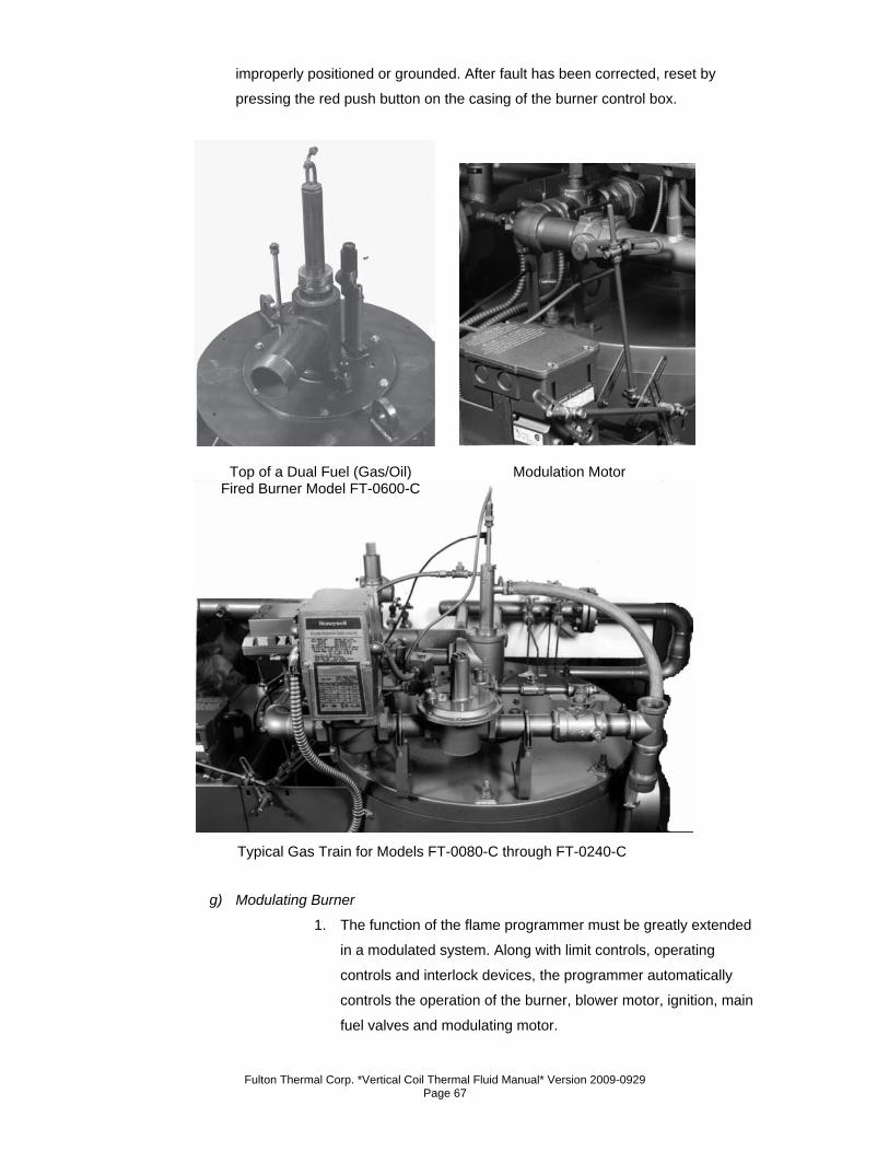
Fulton Thermal Corp. *Vertical Coil Thermal Fluid Manual* Version 2009-0929 Page 67
improperly positioned or grounded. After fault has been corrected, reset by
pressing the red push button on the casing of the burner control box.
g) Modulating Burner
1. The function of the flame programmer must be greatly extended
in a modulated system. Along with limit controls, operating
controls and interlock devices, the programmer automatically
controls the operation of the burner, blower motor, ignition, main
fuel valves and modulating motor.
Top of a Dual Fuel (Gas/Oil) Fired Burner Model FT-0600-C
Modulation Motor
Typical Gas Train for Models FT-0080-C through FT-0240-C
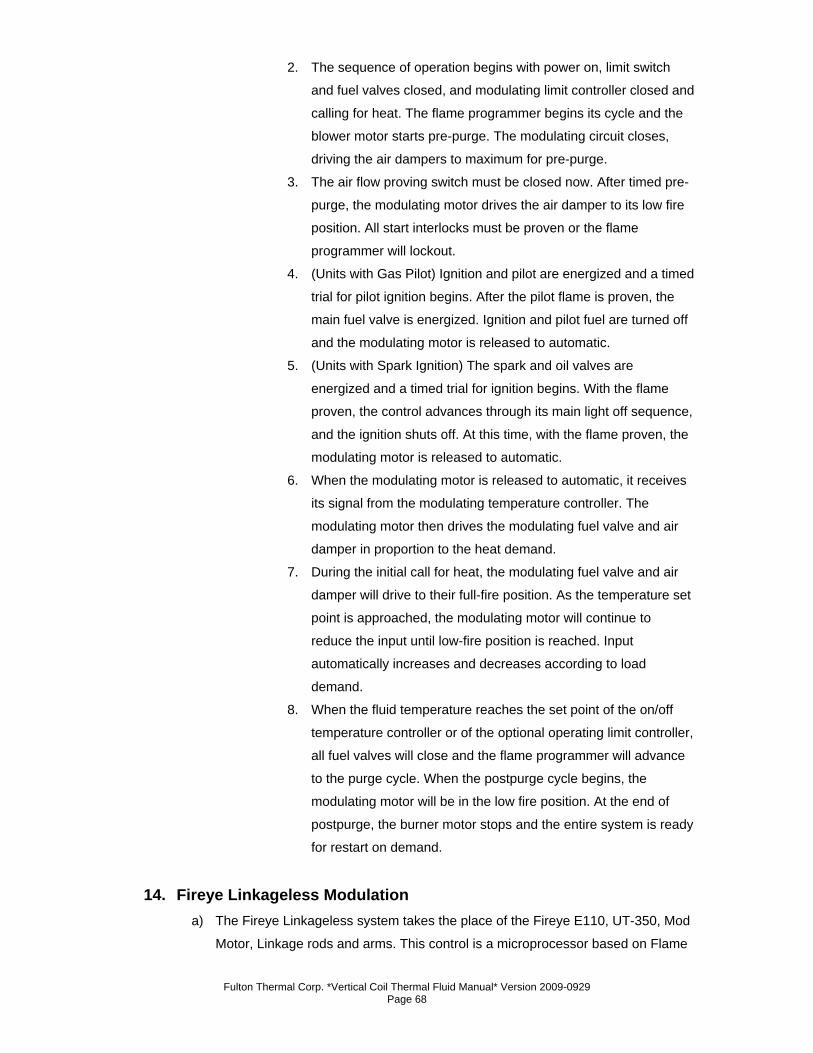
Fulton Thermal Corp. *Vertical Coil Thermal Fluid Manual* Version 2009-0929 Page 68
2. The sequence of operation begins with power on, limit switch
and fuel valves closed, and modulating limit controller closed and
calling for heat. The flame programmer begins its cycle and the
blower motor starts pre-purge. The modulating circuit closes,
driving the air dampers to maximum for pre-purge.
3. The air flow proving switch must be closed now. After timed pre-
purge, the modulating motor drives the air damper to its low fire
position. All start interlocks must be proven or the flame
programmer will lockout.
4. (Units with Gas Pilot) Ignition and pilot are energized and a timed
trial for pilot ignition begins. After the pilot flame is proven, the
main fuel valve is energized. Ignition and pilot fuel are turned off
and the modulating motor is released to automatic.
5. (Units with Spark Ignition) The spark and oil valves are
energized and a timed trial for ignition begins. With the flame
proven, the control advances through its main light off sequence,
and the ignition shuts off. At this time, with the flame proven, the
modulating motor is released to automatic.
6. When the modulating motor is released to automatic, it receives
its signal from the modulating temperature controller. The
modulating motor then drives the modulating fuel valve and air
damper in proportion to the heat demand.
7. During the initial call for heat, the modulating fuel valve and air
damper will drive to their full-fire position. As the temperature set
point is approached, the modulating motor will continue to
reduce the input until low-fire position is reached. Input
automatically increases and decreases according to load
demand.
8. When the fluid temperature reaches the set point of the on/off
temperature controller or of the optional operating limit controller,
all fuel valves will close and the flame programmer will advance
to the purge cycle. When the postpurge cycle begins, the
modulating motor will be in the low fire position. At the end of
postpurge, the burner motor stops and the entire system is ready
for restart on demand.
14. Fireye Linkageless Modulation a) The Fireye Linkageless system takes the place of the Fireye E110, UT-350, Mod
Motor, Linkage rods and arms. This control is a microprocessor based on Flame
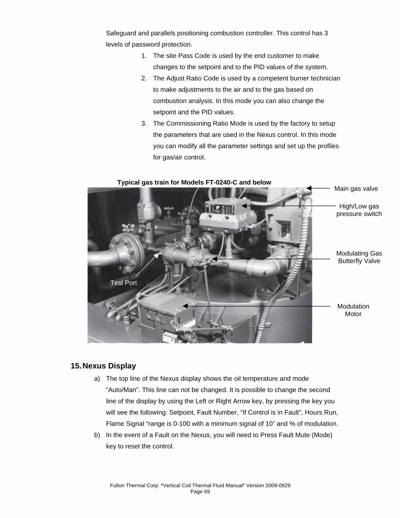
Fulton Thermal Corp. *Vertical Coil Thermal Fluid Manual* Version 2009-0929 Page 69
Safeguard and parallels positioning combustion controller. This control has 3
levels of password protection.
1. The site Pass Code is used by the end customer to make
changes to the setpoint and to the PID values of the system.
2. The Adjust Ratio Code is used by a competent burner technician
to make adjustments to the air and to the gas based on
combustion analysis. In this mode you can also change the
setpoint and the PID values.
3. The Commissioning Ratio Mode is used by the factory to setup
the parameters that are used in the Nexus control. In this mode
you can modify all the parameter settings and set up the profiles
for gas/air control.
15. Nexus Display
a) The top line of the Nexus display shows the oil temperature and mode
“Auto/Man”. This line can not be changed. It is possible to change the second
line of the display by using the Left or Right Arrow key, by pressing the key you
will see the following: Setpoint, Fault Number, “If Control is in Fault”, Hours Run,
Flame Signal “range is 0-100 with a minimum signal of 10” and % of modulation.
b) In the event of a Fault on the Nexus, you will need to Press Fault Mute (Mode)
key to reset the control.
Typical gas train for Models FT-0240-C and below Main gas valve
High/Low gas pressure switch
Modulating Gas Butterfly Valve
Modulation Motor
Test Port
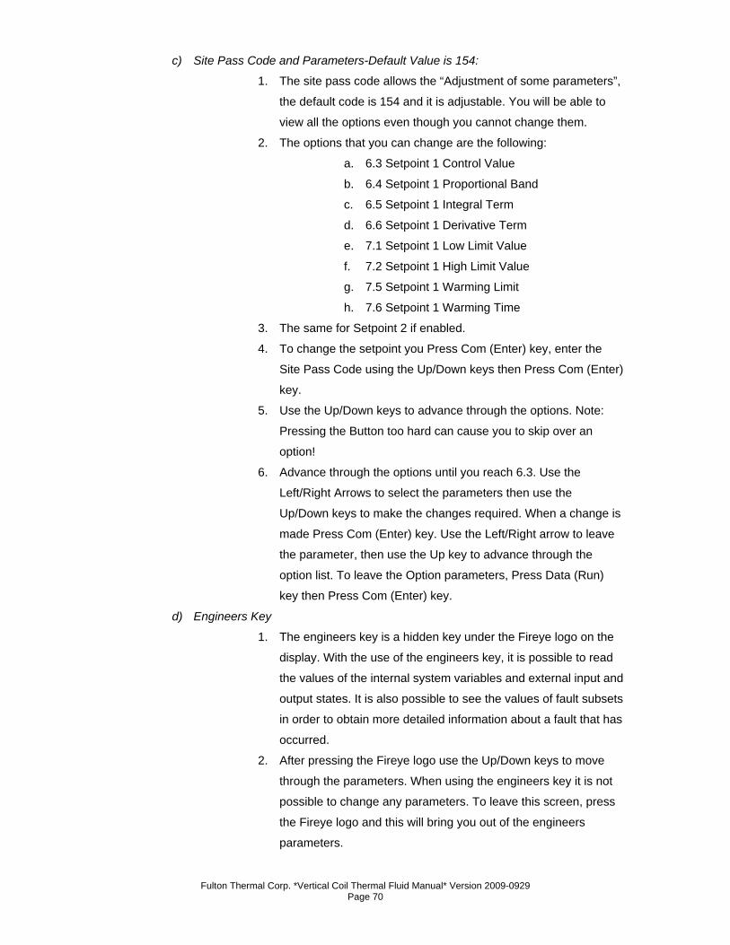
Fulton Thermal Corp. *Vertical Coil Thermal Fluid Manual* Version 2009-0929 Page 70
c) Site Pass Code and Parameters-Default Value is 154:
1. The site pass code allows the “Adjustment of some parameters”,
the default code is 154 and it is adjustable. You will be able to
view all the options even though you cannot change them.
2. The options that you can change are the following:
a. 6.3 Setpoint 1 Control Value
b. 6.4 Setpoint 1 Proportional Band
c. 6.5 Setpoint 1 Integral Term
d. 6.6 Setpoint 1 Derivative Term
e. 7.1 Setpoint 1 Low Limit Value
f. 7.2 Setpoint 1 High Limit Value
g. 7.5 Setpoint 1 Warming Limit
h. 7.6 Setpoint 1 Warming Time
3. The same for Setpoint 2 if enabled.
4. To change the setpoint you Press Com (Enter) key, enter the
Site Pass Code using the Up/Down keys then Press Com (Enter)
key.
5. Use the Up/Down keys to advance through the options. Note:
Pressing the Button too hard can cause you to skip over an
option!
6. Advance through the options until you reach 6.3. Use the
Left/Right Arrows to select the parameters then use the
Up/Down keys to make the changes required. When a change is
made Press Com (Enter) key. Use the Left/Right arrow to leave
the parameter, then use the Up key to advance through the
option list. To leave the Option parameters, Press Data (Run)
key then Press Com (Enter) key.
d) Engineers Key
1. The engineers key is a hidden key under the Fireye logo on the
display. With the use of the engineers key, it is possible to read
the values of the internal system variables and external input and
output states. It is also possible to see the values of fault subsets
in order to obtain more detailed information about a fault that has
occurred.
2. After pressing the Fireye logo use the Up/Down keys to move
through the parameters. When using the engineers key it is not
possible to change any parameters. To leave this screen, press
the Fireye logo and this will bring you out of the engineers
parameters.
Fulton Thermal Corp. *Vertical Coil Thermal Fluid Manual* Version 2009-0929 Page 71
3. The engineers key parameter list begins on page 55 in the
Nexus manual.
e) Nexus Fault Code Display
1. The Nexus 3100 uses the LED lights on the front of the control to
provide diagnostic capability to enable the operator to identify
faults when they occur. The fault listing begins on page 52 of the
Nexus manual.
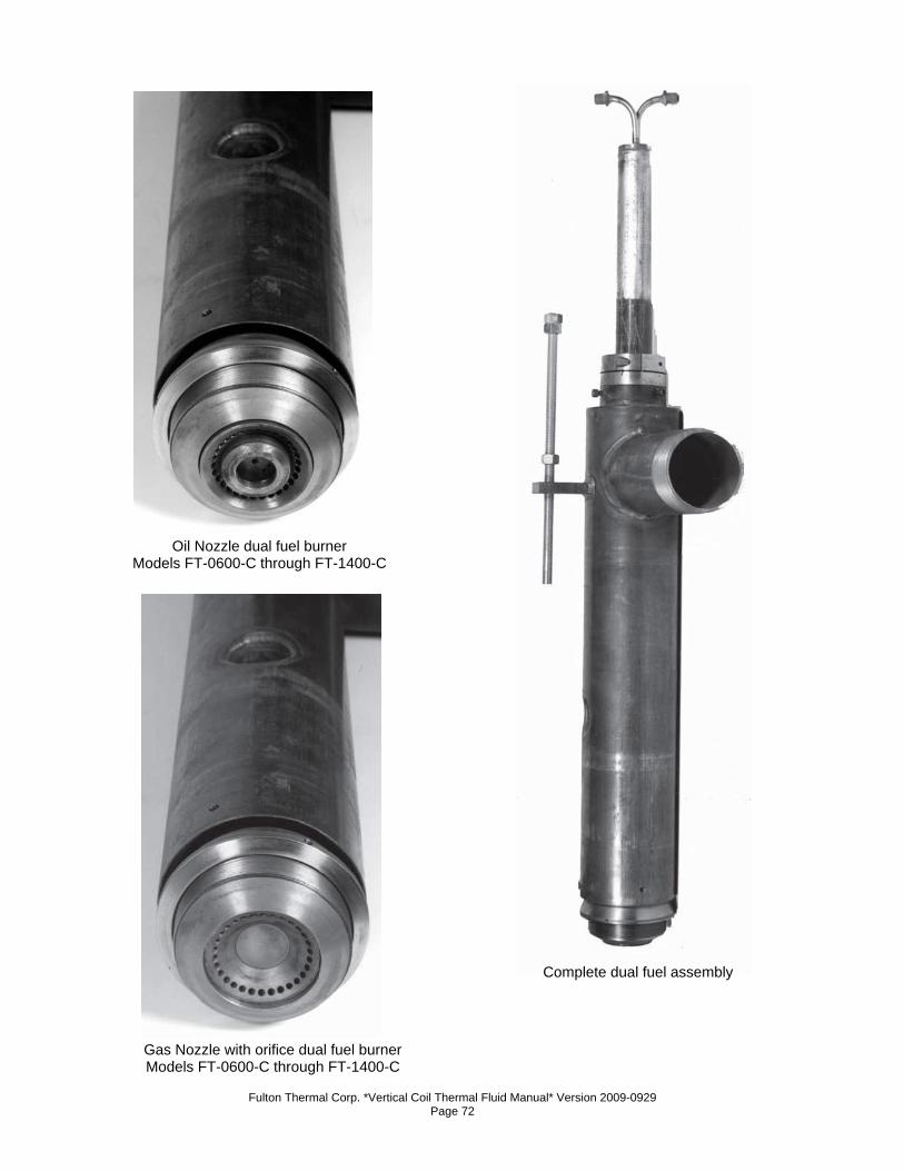
Fulton Thermal Corp. *Vertical Coil Thermal Fluid Manual* Version 2009-0929 Page 72
Gas Nozzle with orifice dual fuel burner Models FT-0600-C through FT-1400-C
Oil Nozzle dual fuel burner Models FT-0600-C through FT-1400-C
Complete dual fuel assembly
Fulton Thermal Corp. *Vertical Coil Thermal Fluid Manual* Version 2009-0929 Page 73
16. Siemens Linkageless Modulation a) Setting Pilot
1. Verify the main burner switch is in the OFF position.
2. Supply power to the heater. The AZL will display “system test”
and them move to the main menu.
3. Select PWLogin, press Enter. Select AccessServ. Press Enter.
(This type of step will be shown as PWLogin – AccessServ for
the remainder of this section. Enter the service passwords using
the arrow key. The password is case sensitive. The case of a
letter can be changed by pressing the other arrow key. (For
example, if you used the right arrow key to get to the letter A,
press the left arrow key to get a). After you have pressed Enter
on the last character of the password, press Enter once more to
accept the password. If you do not have the password, contact
your Fulton Authorized Representative to perform the changes.
Service=NB# or OEM=AAAA (Enter after each A).
4. Select Params&Display. Press Enter. Select Ratio Control. Press
Enter. Select ProgramStop. Press Enter. Change the Program
Stop to 44 Interv1 by using the arrow keys. Confirm the change
by pressing Enter. This will set the burner management system
to a ‘pilot hold’ setting.
5. Verify that the current value “curr” changes to 44 Interv 1. The
full listing of program stops are:
a. 24: Air damper in the prepurge position
b. 32: Traveling to the FGR position (if the unit
is equipped with FGR)
c. 36: Ignition position (before pilot ignition)
d. 44: Ignition position (after pilot ignition)
e. 52: Ignition position (after main burner
ignition)
f. 72: Air damper in the postpurge position
g. 76 – Traveling to the FGR position (if the unit is
equipped with FGR)
6. Press Escape 4 times to get back to the main menu.
7. Under ManualOperation – Setload, change the load to 0% by
using the arrow keys. Press enter and verify the 0% has been
acknowledged in the “curr” field.
8. Press Escape once to get back to the ManualOperation menu.
Fulton Thermal Corp. *Vertical Coil Thermal Fluid Manual* Version 2009-0929 Page 74
9. Under Auto/Manual/Off, change the operation to Burner On by
using the arrow keys. Press enter and verify that “Burner On” is
acknowledged in the current field.
10. Press Escape twice to get back to the main menu.
11. Turn the main burner switch to On position.
12. Increase the set point. Under operation-Heater set point go to set
point W1 using the arrow key then press Enter. Change the set
point under new, using the arrows and press Enter. The new set
point should appear under actual and displayed in degrees.
13. After several seconds the burner control will start its pre-ignition
phase and the blower will start.
14. You can observe the status of the burner by going to the main
menu (by pressing Escape) then selecting OperationalStat –
NormalOperation.
15. The unit will purge then drive to the ignition position and the pilot
should light.
16. The burner control will stay at this pilot hold stage so you can
inspect and adjust the pilot as needed.
a. The pilot gas pressure should match the test fire
sheet.
b. The flame signal should be greater than 90%
when viewed from the top menu of the Siemens
AZL display.
17. Once the pilot is adjusted properly and you are ready to light the
main burner, press Escape to the main menu.
b) Setting Main Burner Ignition
1. Under Params&Display – RatioControl – ProgramStop, change
the Program Stop to 52 Interv2. This is the main burner ignition
position. Press enter and confirm that 52 Interv2 is
acknowledged in the current field. This change moves the control
to the main burner ignition point in the burner sequence.
2. This will allow the main burner to ignite. Should the burner not
light, the gas and air servo motors are not synchronized to
produce a combustible mix.
a) Turn the ON/OFF switch on the panel box to OFF.
b) To reset the alarm: Press Escape on the AZL once.
Press Enter on the AZL to reset the control. The red light
should go out.
Fulton Thermal Corp. *Vertical Coil Thermal Fluid Manual* Version 2009-0929 Page 75
c) To change the setting, return to the front menu by
pressing Escape until you are to the main menu. Then
select Params&Display – RatioControl – GasSettings –
SpecialPositions – IgnitionPos, adjust the gas servo
position by using the arrow key to move down to Gas
servo if needed. Press Enter to select the servo. Move
the gas servo to its new position with the arrow keys.
Press Enter to confirm the new value. Use the down
arrow to move to the air servo setting if needed. Press
Enter to select the servo, use the arrow keys to set the
new value. Press Enter to confirm this.
d) Switch the ON/OFF switch back to ON. The heater will
re-start.
The light off point for main flame can be set at a higher input than low fire. 3. Press Escape 6 times to get back to the main menu.
4. You can observe the status of the burner by going to
OperationalStat – NormalOperation.
5. Verify that the flame signal on the display is great than 90% and
check combustion. Adjust the burner to match the test fire sheet
for main burner ignition. The procedure described in step 2c is
used.
6. Once the ignition position has been adjusted properly, you are
ready to check the burner throughout its modulation range. Press
Escape twice to get back to the main menu.
c) Setting Main Run Modulation
1. Upon releasing the heater to main run modulation (step 3), the
heater will drive to low fire.
2. It is necessary to set combustion through the entire range of
modulation first to enable high fire to be reached. Once high fire
is achieved, the incoming gas pressure can be set. Fine-tuning
of the servo setting throughout the range should be performed
only once high fire settings are confirmed.
Note
If the burner loses flame while driving to a point then:
• Turn the main ON/OFF switch to OFF. Reset the loss of flame fault. Press Escape on the AZL once. Press Enter on the AZL to reset the control. The red light on the panel box door should go out.
Fulton Thermal Corp. *Vertical Coil Thermal Fluid Manual* Version 2009-0929 Page 76
• Adjust the air and gas servos for that point while the burner is off. Follow steps d1-d2 below.
• Turn the main ON/OFF switch to ON.
3. Under Params&Display – RatioControl – GasSettings –
ProgramStop, change the program stop to deactivated by using
the arrow keys. Confirm that ‘deactivated’ is acknowledged in
the current field.
4. This change will allow the burner to modulate. The burner will
now drive to low fire.
Remember, it is only important at this stage to set low fire to be stable and with clean combustion. Exact setting is to be performed once high fire is confirmed.
5. Press Escape 5 times to get back to the main menu.
6. You can observe the status of the burner By going to
OperationalStat/NormalOperation.
7. Verify the flame signal on the display, measure input if gas meter
is available. If not, match last elbow pressures and combustion
for test fire sheet. Adjust the burner as needed.
To adjust the servo position, follow steps 1-2 below.
d) Setting Low Fire
Note
As soon as a servo position is altered, the servo will move to that position. Only change servo settings by a maximum of 0.5° at a time before verifying combustion.
1. Go to Params&Display – RatioControl – GasSettings –
CurveParams.
2. Wait for the spinning line on the left to disappear. Press Enter.
The number 1 should appear to the right of the cursor, this is the
Point Number.
3. Press Enter once. Select ChangePoint by pressing the arrow
keys to highlight and then press Enter to select. This will cause
the servo motors to move to this low fire point.
Fulton Thermal Corp. *Vertical Coil Thermal Fluid Manual* Version 2009-0929 Page 77
4. Check combustion and adjust the servo motors as required. To
adjust a servo motor, arrow to it and press Enter. Then adjust the
setting as required and press Enter. You can now adjust another
servo motor if needed.
5. When combustion is properly set for that point, press Escape
once more. If it asks you to store the point, press Enter. Note the
AZL will only ask to save if either servo value has been altered.
6. Low fire is now set and stored.
e) Setting the Complete Range
1. Remember it is only necessary to approximate the setting
through the modulation range until high fire conditions are
established.
2. Press Enter once more to have access to the point number field.
Increase the point number by one and press Enter. Select
ChangePoint and press Enter. The servos will now move to that
point.
3. Verify combustion is satisfactory.
4. Measure input or monitor last elbow pressure. Verify that these
points are in general correspondence with the test fire sheet.
Repeat step 2 until the point position has a load value of 100%.
You are now at high fire. Verify combustion is per test fire sheet.
5. Once at high fire, adjust the incoming gas pressure at the main
gas regulator to match the test fire report. Adjust the gas servo
motor to change the last elbow pressure to match the test fire
report. Adjust the air servo motor to adjust the emissions as
needed.
6. Repeat step d1 but start at the high fire point number.
Continually decrease the point number after combustion has
been verified at each point.
7. Once all the points have been verified, press Escape until you
are back to the main menu.
8. You can observe the status of the burner by going to
OperationalStat – NormalOperation.
9. Turn the main ON/OFF switch to OFF. The control will now
postpurge.
10. Follow steps 16a3-17 and b1-4 again to verify ignition with the
new gas pressures.
11. Turn the main burner switch to OFF. The control will now post
purge.
Fulton Thermal Corp. *Vertical Coil Thermal Fluid Manual* Version 2009-0929 Page 78
12. Under Manual Operation – Auto/Manual/Off, change the
operation to Automatic and press Enter and confirm Automatic is
entered in the current field.
13. Press Escape twice to get back to the main menu.
14. Under Updating – ParamBackup, select LMV51 – AZL. This will
store all of the adjustments that have been made in the LMV
base module to the display. If the base module fails in the future,
the display can be used to download all of the parameters into a
new base module.
15. The heater is now ready to run. Adjust your setpoint on the
temperature control to the desired temperature and turn the main
ON/OFF switch to ON for the burner to operate.
f) Before Leaving the Installation
1. Check all controls to insure they are operating properly. Cycle
the heater several times by raising and lowering operating
temperature on the thermostat.
2. Make sure the installation complies with all applicable codes.
g) Changing Set Point on the AZL
1. Hit ESC to Select Operation than hit enter and scroll to Heater
Set point, hit enter to Set point W1 hit enter and enter new set
point with Select buttons.
2. Done hit enter than ESC 3 times to Operational Stats hit enter to
Normal Operation, hit enter to main screen.
h) For Manual Operation
1. Hit ESC and scroll to Manual, hit enter to Auto / Manual / Off,
change to manual and hit ESC to Set Load, change to 0 or
desired load range with the select buttons.
2. Done hit ESC and scroll to Operational Stats, hit enter to Normal
Operation, hit enter to main screen.
3. To return back to Auto operation repeat step 1 & 2.
i) Replacing a Servo Motor
1. If it is determined that a servo motor needs to be replaced, the
first step in this process is to verify the model number of the new
servo motor is the same as the old servo motor.
2. The model number starts with the letter SQM and is displayed on
a label on the side of the motor. Once the new motor has been
verified to be correct, turn power to the heater off.
3. Turn off all electricity to the heater.
4. Remove the cover on the servo motor to be changed.
Fulton Thermal Corp. *Vertical Coil Thermal Fluid Manual* Version 2009-0929 Page 79
5. Remove the green wiring plugs and the conduit termination point
from the motor by pulling them towards you. A black grounding
wire runs from the motor to the conduit termination point. Pull it
off from the conduit termination point.
6. Also note the location of the jumper of the left side of the motor.
7. Loosen the allen screws on the motor end of the motor end of
the motor to valve coupling.
8. Unbolt the motor from the mounting bracket and remove the
motor.
9. Turn the valve so it is in the closed position and can rotate
clockwise to open.
10. Mark the coupling or valve shaft if needed so the position of the
valve can be determined when the servo motor is installed.
11. Bolt the new servo motor on to the mounting bracket with the
motor shaft inserted into the coupling.
12. Rotate the valve shaft/coupling assembly closed as stated
above.
13. While holding the valve closed, tighten the allen screws on the
coupling.
14. Install the wired green wiring plugs and the conduit termination
point on the new motor. Connect the black grounding wire form
the motor to the conduit termination point.
15. Verify the jumper on the motor is located on the same pins as
the motor that was replaced.
16. Turn power to the heater on.
17. The screen will display ‘system test’. The fault “Fault Feedback
Air Actuator’ will be displayed. DO NOT RESET THIS FAULT
YET. Press Escape twice to clear the fault from the screen.
18. Press Escape to get to the main menu. Under Params&Display –
Actuators – Addressing, select either the gas actuator or air
actuator depending upon which was replaced. The control will
run an actuator check then display ‘Start Address Assignment
with ENTER’. Press Enter. The display will then have you press
the addressing button on the actuator. This is the red button on
the actuator. The screen will then display ‘Actuator Address
Assignment Successful’.
19. Press Escape until the main menu is reached. Under
OperationStat – Status/Reset, reset the fault.
Fulton Thermal Corp. *Vertical Coil Thermal Fluid Manual* Version 2009-0929 Page 80
Caution
The heater emissions may not be correct after changing the servo motor. Verify the emissions throughout the range of modulation. If emissions are off, the servo motor can be adjusted by following the procedure in the Commissioning the Heater section of this manual.
17. On/Off Burner a) The sequence of operation begins with power on, limit switch and fuel valves
closed, and temperature controller calling for heat. The flame programmer begins
the cycle and the blower motor starts prepurge.
b) The air proving switch must be closed now. Air dampers remain in maximum
position.
c) (Gas Pilot) Provided all safety interlocks are proven, ignition and pilot are
energized and a timed trial for pilot ignition begins. After the pilot flame is proven,
the main fuel valve is energized. Ignition is turned off after main flame is
established.
d) (Spark Ignition) Provided all safety interlocks are proven, the spark is on and oil
valves are opened. When the flame is proven, the spark is shut off.
e) When the fluid temperature reaches the setpoint of the operating temperature
controller, all fuel valves are closed.
f) The burner motor stops and the entire system is ready for restart on demand.
18. Oil Fired Burner a) The following refers to the design and operation of the on/off burner utilizing fuel
oil which requires no preheating. This burner is of high pressure, mechanical
atomization design.
b) An oil pump is used to obtain necessary atomizing pressure before the fuel oil
reaches the nozzle.
c) The fuel oil is divided into fine particles in the nozzle and imparted with a rotating
motion before escaping from the nozzle as a cone of finely atomized oil.
d) Combustion air is supplied by a centrifugal fan. A damper provides throttling of
the inlet opening. The air from the fan reaches the burner head after going
through a turbulator, accomplishing correct distribution and mixture of air and
atomized fuel oil.
e) An electric spark between two electrodes provides ignition of the atomized
mixture, except where code requires a gas pilot. This spark is produced by a high
voltage transformer.
Fulton Thermal Corp. *Vertical Coil Thermal Fluid Manual* Version 2009-0929 Page 81
f) The flame programmer circuit controls normal operation of the burner. The
sequence includes purging of the combustion area for a set period, ignition and
opening of magnetic valves on the oil circuit; post-purge of combustion area and
return to re-start position.
g) An ultra-violet scanner mounted on the burner casing and facing the light of the
flame monitors the flame.
h) Safety lock out occurs within a preset minimum time in the event of insufficient,
unstable or non-existent flame. After fault has been corrected, reset programmer
by depressing the red push button on the casing of the burner control box.
i) Proper fuel pressure at the burner nozzle is essential. The correct firing rate is
obtained by setting the fuel oil pump to give the design pressure for each unit.
This is done at the factory.
j) Pressure is measured by connecting a 0-400 PSI (0-25 bar) test pressure gauge
to the gauge connection on the fuel pump. The fuel pressure gauge indicates the
pressure of the fuel at the burner nozzle.
k) Typical pressures range between 160-350 PSI (12-22 bar). Note the correct
setting upon commissioning. Modulating units should have a second pressure
gauge monitoring the pressure in the return pipe from the burner. This gauge will
indicate the variation of oil flow caused by modulation of the burner. Gauge
readings should be recorded at start-up and checked periodically.
19. Dual Fuel Burner Changing Fuel
a) The following instructions apply only to units supplied with dual fuel burners.
These procedures should be performed only when the fluid is cold, unless
sufficient safeguards are provided to prevent contact with hot fluid piping in the
vicinity of the burner.
b) Set the fuel switch to “Off” and the heat selector switch to either “Pump” or “Off”.
c) Gas to Oil
1. Turn off the manual gas cocks in the gas train. Remove the gas
nozzle orifice assembly from the burner. Install the oil nozzle
assembly and attach the oil whips to the assembly. Open all oil
manual shutoff valves.
d) Oil to Gas
1. Turn off all oil manual shutoff valves. Detach the oil whips and
remove the oil nozzle assembly. Install the gas nozzle orifice
assembly and open the gas cocks in the gas train. Reset the
hi/low gas pressure switch.
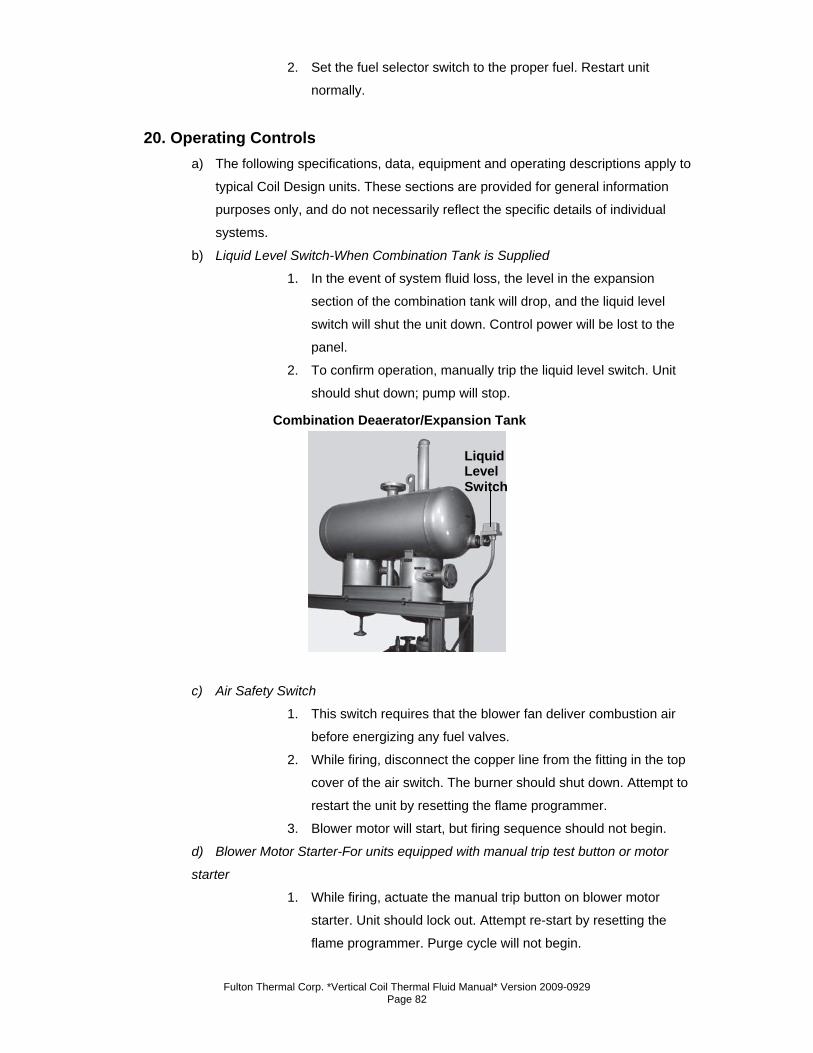
Fulton Thermal Corp. *Vertical Coil Thermal Fluid Manual* Version 2009-0929 Page 82
2. Set the fuel selector switch to the proper fuel. Restart unit
normally.
20. Operating Controls a) The following specifications, data, equipment and operating descriptions apply to
typical Coil Design units. These sections are provided for general information
purposes only, and do not necessarily reflect the specific details of individual
systems.
b) Liquid Level Switch-When Combination Tank is Supplied
1. In the event of system fluid loss, the level in the expansion
section of the combination tank will drop, and the liquid level
switch will shut the unit down. Control power will be lost to the
panel.
2. To confirm operation, manually trip the liquid level switch. Unit
should shut down; pump will stop.
c) Air Safety Switch
1. This switch requires that the blower fan deliver combustion air
before energizing any fuel valves.
2. While firing, disconnect the copper line from the fitting in the top
cover of the air switch. The burner should shut down. Attempt to
restart the unit by resetting the flame programmer.
3. Blower motor will start, but firing sequence should not begin.
d) Blower Motor Starter-For units equipped with manual trip test button or motor
starter
1. While firing, actuate the manual trip button on blower motor
starter. Unit should lock out. Attempt re-start by resetting the
flame programmer. Purge cycle will not begin.
Liquid Level Switch
Combination Deaerator/Expansion Tank
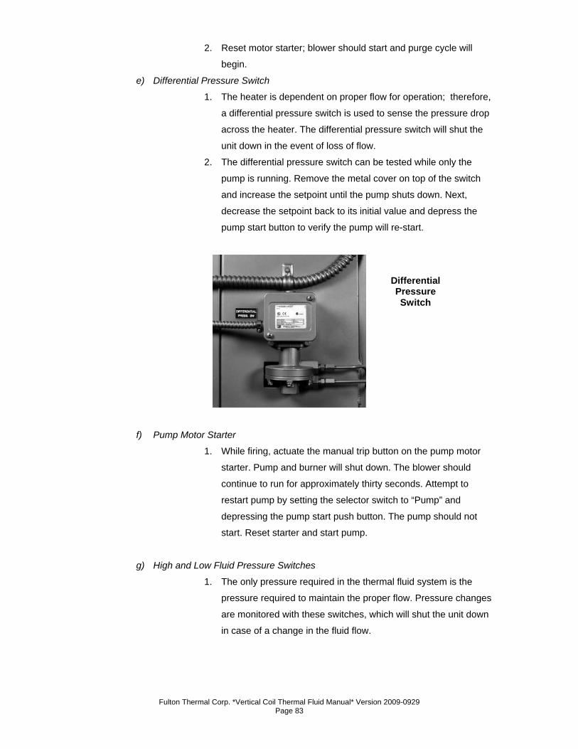
Fulton Thermal Corp. *Vertical Coil Thermal Fluid Manual* Version 2009-0929 Page 83
2. Reset motor starter; blower should start and purge cycle will
begin.
e) Differential Pressure Switch
1. The heater is dependent on proper flow for operation; therefore,
a differential pressure switch is used to sense the pressure drop
across the heater. The differential pressure switch will shut the
unit down in the event of loss of flow.
2. The differential pressure switch can be tested while only the
pump is running. Remove the metal cover on top of the switch
and increase the setpoint until the pump shuts down. Next,
decrease the setpoint back to its initial value and depress the
pump start button to verify the pump will re-start.
f) Pump Motor Starter
1. While firing, actuate the manual trip button on the pump motor
starter. Pump and burner will shut down. The blower should
continue to run for approximately thirty seconds. Attempt to
restart pump by setting the selector switch to “Pump” and
depressing the pump start push button. The pump should not
start. Reset starter and start pump.
g) High and Low Fluid Pressure Switches
1. The only pressure required in the thermal fluid system is the
pressure required to maintain the proper flow. Pressure changes
are monitored with these switches, which will shut the unit down
in case of a change in the fluid flow.
Differential Pressure Switch
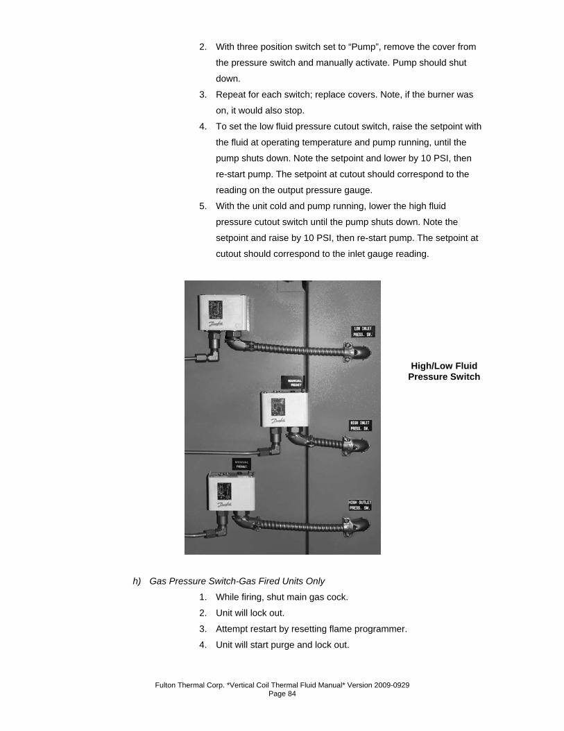
Fulton Thermal Corp. *Vertical Coil Thermal Fluid Manual* Version 2009-0929 Page 84
2. With three position switch set to “Pump”, remove the cover from
the pressure switch and manually activate. Pump should shut
down.
3. Repeat for each switch; replace covers. Note, if the burner was
on, it would also stop.
4. To set the low fluid pressure cutout switch, raise the setpoint with
the fluid at operating temperature and pump running, until the
pump shuts down. Note the setpoint and lower by 10 PSI, then
re-start pump. The setpoint at cutout should correspond to the
reading on the output pressure gauge.
5. With the unit cold and pump running, lower the high fluid
pressure cutout switch until the pump shuts down. Note the
setpoint and raise by 10 PSI, then re-start pump. The setpoint at
cutout should correspond to the inlet gauge reading.
h) Gas Pressure Switch-Gas Fired Units Only
1. While firing, shut main gas cock.
2. Unit will lock out.
3. Attempt restart by resetting flame programmer.
4. Unit will start purge and lock out.
High/Low Fluid Pressure Switch
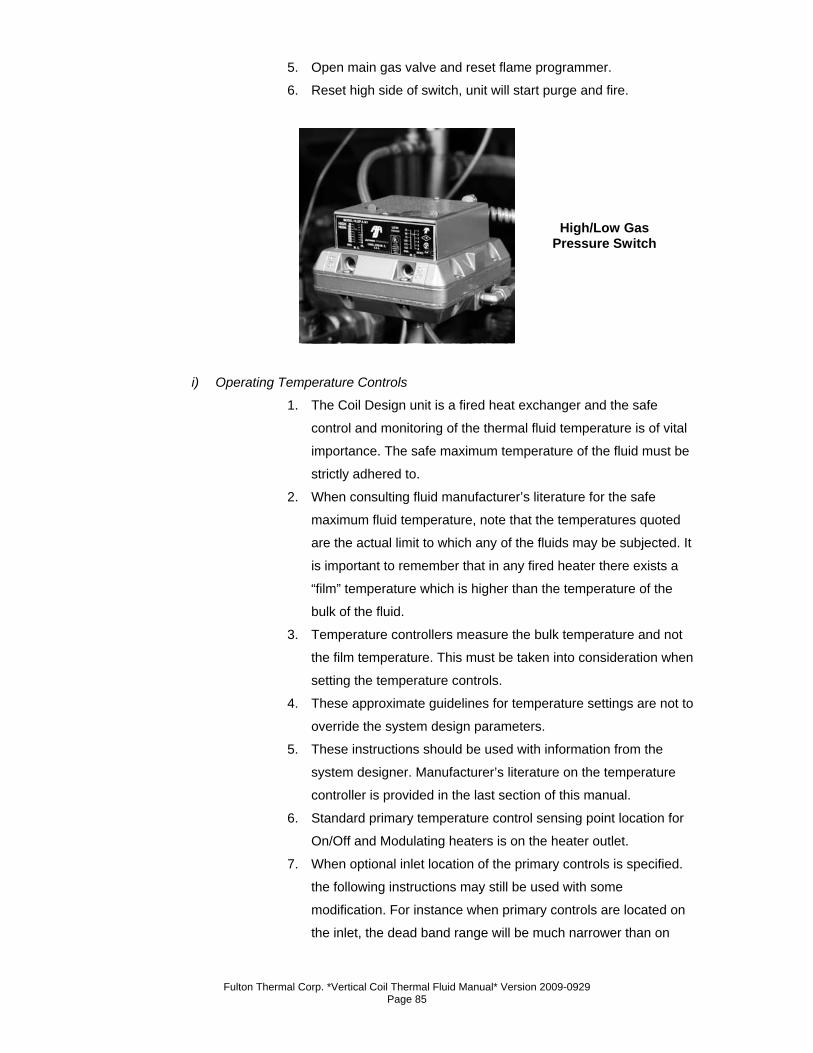
Fulton Thermal Corp. *Vertical Coil Thermal Fluid Manual* Version 2009-0929 Page 85
5. Open main gas valve and reset flame programmer.
6. Reset high side of switch, unit will start purge and fire.
i) Operating Temperature Controls
1. The Coil Design unit is a fired heat exchanger and the safe
control and monitoring of the thermal fluid temperature is of vital
importance. The safe maximum temperature of the fluid must be
strictly adhered to.
2. When consulting fluid manufacturer’s literature for the safe
maximum fluid temperature, note that the temperatures quoted
are the actual limit to which any of the fluids may be subjected. It
is important to remember that in any fired heater there exists a
“film” temperature which is higher than the temperature of the
bulk of the fluid.
3. Temperature controllers measure the bulk temperature and not
the film temperature. This must be taken into consideration when
setting the temperature controls.
4. These approximate guidelines for temperature settings are not to
override the system design parameters.
5. These instructions should be used with information from the
system designer. Manufacturer’s literature on the temperature
controller is provided in the last section of this manual.
6. Standard primary temperature control sensing point location for
On/Off and Modulating heaters is on the heater outlet.
7. When optional inlet location of the primary controls is specified.
the following instructions may still be used with some
modification. For instance when primary controls are located on
the inlet, the dead band range will be much narrower than on
High/Low Gas Pressure Switch
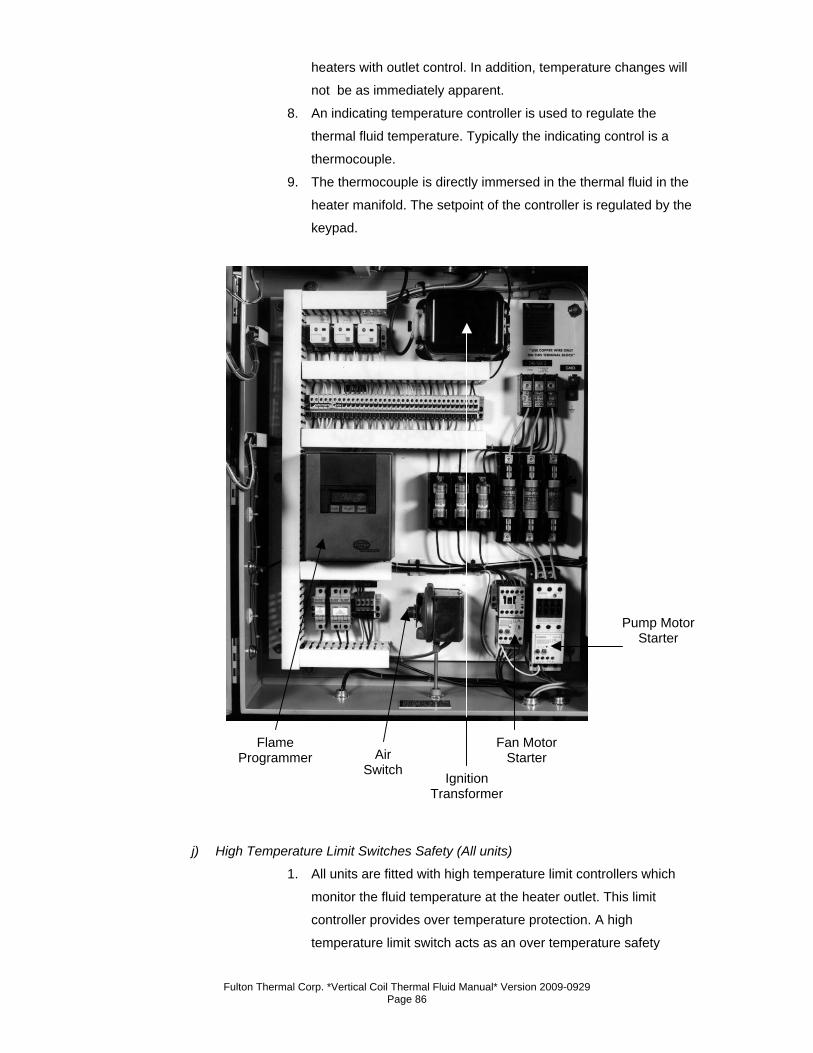
Fulton Thermal Corp. *Vertical Coil Thermal Fluid Manual* Version 2009-0929 Page 86
heaters with outlet control. In addition, temperature changes will
not be as immediately apparent.
8. An indicating temperature controller is used to regulate the
thermal fluid temperature. Typically the indicating control is a
thermocouple.
9. The thermocouple is directly immersed in the thermal fluid in the
heater manifold. The setpoint of the controller is regulated by the
keypad.
j) High Temperature Limit Switches Safety (All units)
1. All units are fitted with high temperature limit controllers which
monitor the fluid temperature at the heater outlet. This limit
controller provides over temperature protection. A high
temperature limit switch acts as an over temperature safety
Flame Programmer Air
Switch Ignition Transformer
Fan Motor Starter
Pump Motor Starter
Fulton Thermal Corp. *Vertical Coil Thermal Fluid Manual* Version 2009-0929 Page 87
device. If the high temperature limit shuts down the unit, the
manual reset button on the limit switch must be pressed. The red
button on the flame programmer must also be pressed to reset
the unit before it can be restarted. The high temperature limit
controller is factory set to 0°F. This must be set to the lowest of
the following:
a. Maximum operating temperature of the fluid.
b. Maximum operating temperature of the equipment.
c. 15°F over maximum system operating temperature.
2. Do not set this controller too close to the normal outlet
temperature in order to avoid nuisance lockouts due to small
transient over temperatures.
3. Several consecutive lockouts caused by the high temperature
limit controller indicate the need for immediate installation
review, beginning with fluid level in the expansion tank, firing
rate, and circulating pump performance.
k) Operating Limit Controller
1. The limit controller is mounted in the panel box door. This limit
controller senses temperature in the outlet manifold. The
temperature setpoint in the controller can be adjusted following
instructions in the component data sheet section of this manual.
l) On/Off Controls
1. Typically one controller is provided to sense the temperature on
the heater outlet. This controls the operation of the heater by
switching it on and off. An adjustable two point differential
between shut off and start up is built into the controller. This
prevents frequent cycling of the burner. The controller is set to
provide the desired outlet fluid temperature.
2. Due to the temperature rise through the unit, this may be
considerably higher than the inlet temperature.
3. If the unit is equipped with an on/off controller, it will be located
on the face of the electrical cabinet. The temperature setpoint in
the controller can be adjusted following the instructions in the
component data sheets section of this manual.
m) Modulating Controls
1. All coil models are standardly equipped with modulating controls.
2. The modulating temperature controller continuously regulates
the outlet fluid temperature between the minimum firing rate and
high fire. When the unit is on low fire and the temperature
Fulton Thermal Corp. *Vertical Coil Thermal Fluid Manual* Version 2009-0929 Page 88
continues to climb past the setpoint, the heater will shut down. It
will typically re-start when the process temperature drops 7°F
below setpoint.
3. Minimum load depends on the degree of modulation provided.
Typically 3:1 or 5:1 modulation is provided. In this case minimum
load is one third of full firing rate.
4. The modulating temperature controller is set to maintain the
desired fluid outlet temperature. Due to the temperature rise
across the heater, this may be considerably higher than the inlet
temperature.
5. If the unit is equipped with a modulating controller, it will be
located on the face of the electrical cabinet. The temperature
setpoint in the controller can be adjusted following the
instructions in the component data sheet section of this manual.
n) Additional Modulating Controls
1. The modulating motor is controlled by a temperature controller
located in the control panel. Its function is to drive modulating
fuel valves and air damper to their correct position as dictated by
the flame programmer during pre-purge and post-purge, and to
correctly position both during the normal firing cycle as required
by the proportioning temperature controller. A modulating valve
is positioned in the main fuel line to control the fuel input
according to demand by the modulating motor.
o) Pressure Gauges
1. All units have two pressure gauges measuring the thermal fluid
pressure at the inlet of the heater and at the outlet of the heater.
The difference between the readings of the two gauges indicates
the pressure loss across the heater. The difference must not fall
below the recommended value. Recommendations are based on
heater size and are listed in Section Two.
2. The gauge indicating the pressure of the fluid at the inlet is
labeled “Inlet“. The “Outlet” gauge indicates the pressure at the
outlet, and in effect indicates the resistance of the external
pipework circuit. The pressure gauge indicating pressure at the
inlet of the pump is labeled “Suction .”
p) Flow Proving Device
1. The heater is dependent on proper flow for operation; therefore,
three pressure switches and a differential pressure switch are
Fulton Thermal Corp. *Vertical Coil Thermal Fluid Manual* Version 2009-0929 Page 89
used to sense flow across the heater. Any one of these switches
will shut the unit down in the event of loss of flow.
21. Daily Start-Up a) Check positioning of all system valves to ensure flow is not dead-headed.
b) Visually check relative position of minimum level float switch in the combination
tank.
c) Turn on power supply switches.
d) Where applicable, open water cooling valve and check that water flows correctly.
(For water cooled pumps only.)
e) Open fuel valves.
f) Set three position switch to “Pump”. Push and hold manual pump start button,
monitoring pressure gauges on heater.
g) Push reset on high fluid pressure switch located on the side of the control panel.
Release pump start switch. Pump should continue to run.
h) When ready to begin heating, move three position switch from “Pump” to “Heat”.
After a short delay resulting from the purge period, the burner will ignite. Make
sure that the temperature setpoint is as desired.
i) On gas units, pilot valve activation will be indicated after pre-purge cycle has
completed, followed by main flame activation. Check the presence of the flame
by observing flame signal strength from flame programmer or testing device.
Operator attendance during warm-up is a recommended precaution.
j) Start-up is considered complete when the unit begins to throttle back or
shutdown on target temperature.
22. Daily Shutdown a) Set control switch to “Pump” pump running, burner off.
b) Allow the fluid to circulate for approximately 20-30 minutes and then set the
control switch to the “Off” position.
c) When using fluid cooled pump, continue to circulate cooling water to pumps for
30 minutes after stopping circulation.
d) Open power supply switches.
e) Units switched off by an automatic time switch should have an extra relay fitted to
allow 20-30 minutes of fluid circulation after stoppage in order to prevent
localized over heating of fluid .
f) Close fuel valves if required. Closing of system valves is not generally necessary
unless maintenance of components requires a partial draining of the system.
Fulton Thermal Corp. *Vertical Coil Thermal Fluid Manual* Version 2009-0929 Page 90
g) Because of the high temperatures usually applied, leaks are not expected to
occur when cool down is achieved, provided pipework is free to contract naturally
when cold.
Fulton Thermal Corp. *Vertical Coil Thermal Fluid Manual* Version 2009-0929 Page 91
Section 4

Fulton Thermal Corp. *Vertical Coil Thermal Fluid Manual* Version 2009-0929 Page 92
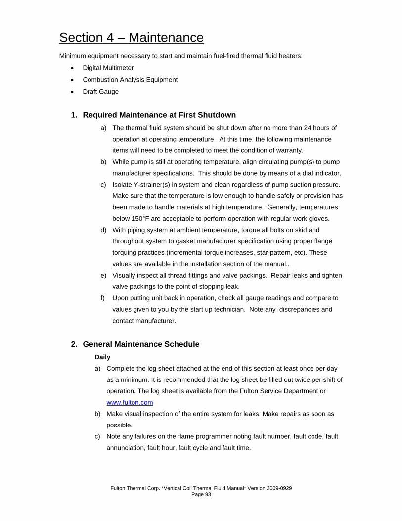
Fulton Thermal Corp. *Vertical Coil Thermal Fluid Manual* Version 2009-0929 Page 93
Section 4 – Maintenance Minimum equipment necessary to start and maintain fuel-fired thermal fluid heaters:
• Digital Multimeter
• Combustion Analysis Equipment
• Draft Gauge
1. Required Maintenance at First Shutdown a) The thermal fluid system should be shut down after no more than 24 hours of
operation at operating temperature. At this time, the following maintenance
items will need to be completed to meet the condition of warranty.
b) While pump is still at operating temperature, align circulating pump(s) to pump
manufacturer specifications. This should be done by means of a dial indicator.
c) Isolate Y-strainer(s) in system and clean regardless of pump suction pressure.
Make sure that the temperature is low enough to handle safely or provision has
been made to handle materials at high temperature. Generally, temperatures
below 150°F are acceptable to perform operation with regular work gloves.
d) With piping system at ambient temperature, torque all bolts on skid and
throughout system to gasket manufacturer specification using proper flange
torquing practices (incremental torque increases, star-pattern, etc). These
values are available in the installation section of the manual..
e) Visually inspect all thread fittings and valve packings. Repair leaks and tighten
valve packings to the point of stopping leak.
f) Upon putting unit back in operation, check all gauge readings and compare to
values given to you by the start up technician. Note any discrepancies and
contact manufacturer.
2. General Maintenance Schedule Daily a) Complete the log sheet attached at the end of this section at least once per day
as a minimum. It is recommended that the log sheet be filled out twice per shift of
operation. The log sheet is available from the Fulton Service Department or
www.fulton.com
b) Make visual inspection of the entire system for leaks. Make repairs as soon as
possible.
c) Note any failures on the flame programmer noting fault number, fault code, fault
annunciation, fault hour, fault cycle and fault time.
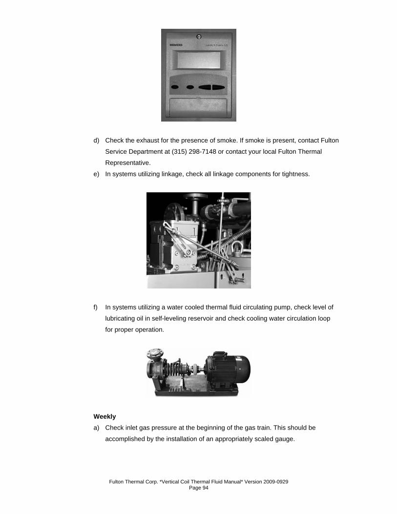
Fulton Thermal Corp. *Vertical Coil Thermal Fluid Manual* Version 2009-0929 Page 94
d) Check the exhaust for the presence of smoke. If smoke is present, contact Fulton
Service Department at (315) 298-7148 or contact your local Fulton Thermal
Representative.
e) In systems utilizing linkage, check all linkage components for tightness.
f) In systems utilizing a water cooled thermal fluid circulating pump, check level of
lubricating oil in self-leveling reservoir and check cooling water circulation loop
for proper operation.
Weekly a) Check inlet gas pressure at the beginning of the gas train. This should be
accomplished by the installation of an appropriately scaled gauge.
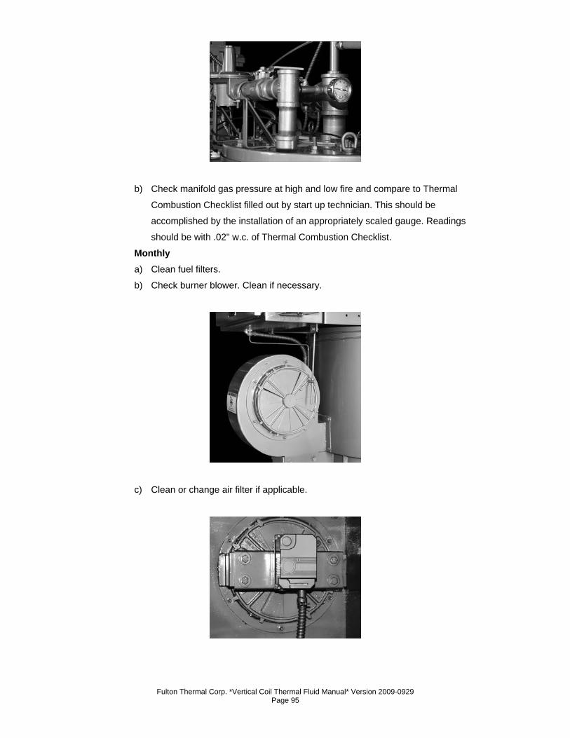
Fulton Thermal Corp. *Vertical Coil Thermal Fluid Manual* Version 2009-0929 Page 95
b) Check manifold gas pressure at high and low fire and compare to Thermal
Combustion Checklist filled out by start up technician. This should be
accomplished by the installation of an appropriately scaled gauge. Readings
should be with .02" w.c. of Thermal Combustion Checklist.
Monthly a) Clean fuel filters.
b) Check burner blower. Clean if necessary.
c) Clean or change air filter if applicable.
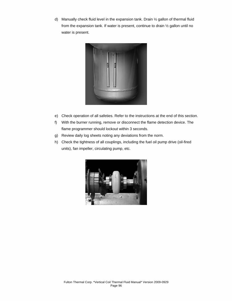
Fulton Thermal Corp. *Vertical Coil Thermal Fluid Manual* Version 2009-0929 Page 96
d) Manually check fluid level in the expansion tank. Drain ½ gallon of thermal fluid
from the expansion tank. If water is present, continue to drain ½ gallon until no
water is present.
e) Check operation of all safeties. Refer to the instructions at the end of this section.
f) With the burner running, remove or disconnect the flame detection device. The
flame programmer should lockout within 3 seconds.
g) Review daily log sheets noting any deviations from the norm.
h) Check the tightness of all couplings, including the fuel oil pump drive (oil-fired
units), fan impeller, circulating pump, etc.
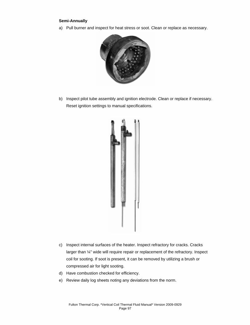
Fulton Thermal Corp. *Vertical Coil Thermal Fluid Manual* Version 2009-0929 Page 97
Semi-Annually a) Pull burner and inspect for heat stress or soot. Clean or replace as necessary.
b) Inspect pilot tube assembly and ignition electrode. Clean or replace if necessary.
Reset ignition settings to manual specifications.
c) Inspect internal surfaces of the heater. Inspect refractory for cracks. Cracks
larger than ¼" wide will require repair or replacement of the refractory. Inspect
coil for sooting. If soot is present, it can be removed by utilizing a brush or
compressed air for light sooting.
d) Have combustion checked for efficiency.
e) Review daily log sheets noting any deviations from the norm.
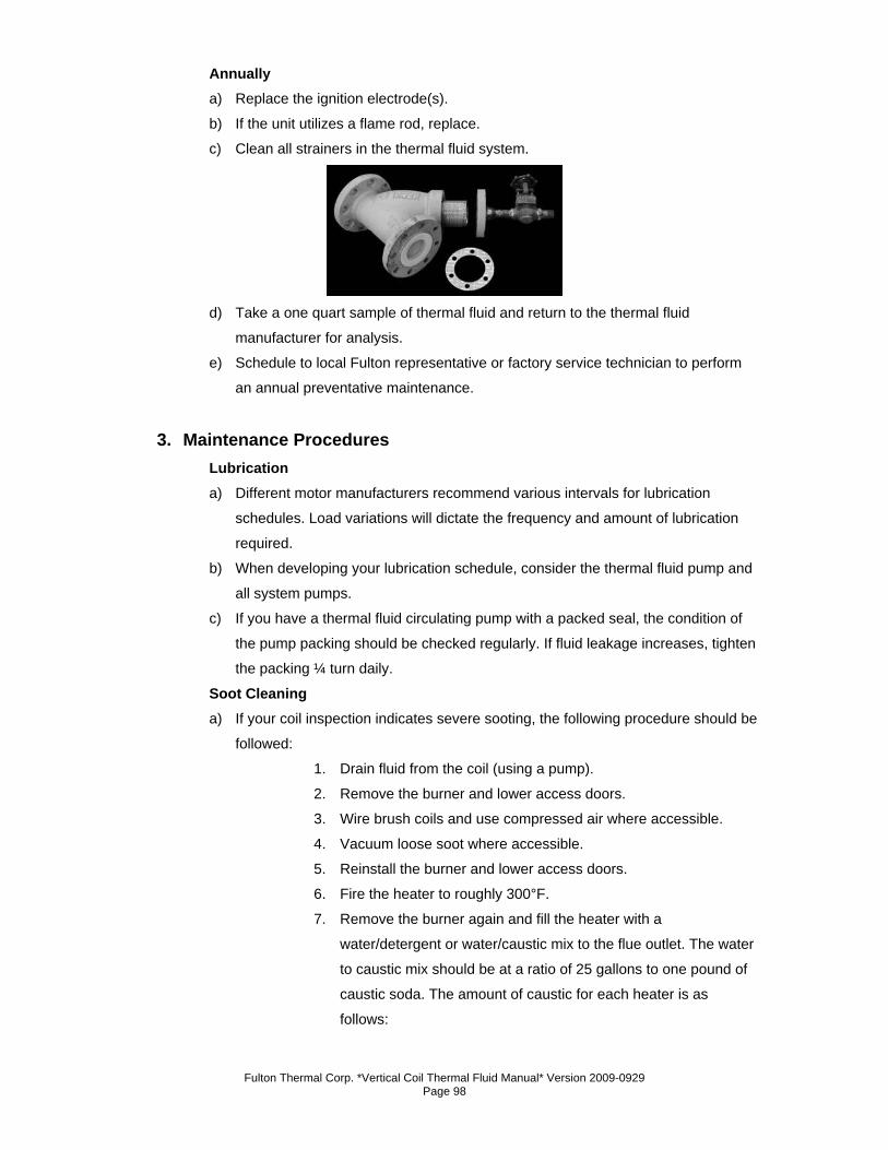
Fulton Thermal Corp. *Vertical Coil Thermal Fluid Manual* Version 2009-0929 Page 98
Annually a) Replace the ignition electrode(s).
b) If the unit utilizes a flame rod, replace.
c) Clean all strainers in the thermal fluid system.
d) Take a one quart sample of thermal fluid and return to the thermal fluid
manufacturer for analysis.
e) Schedule to local Fulton representative or factory service technician to perform
an annual preventative maintenance.
3. Maintenance Procedures Lubrication a) Different motor manufacturers recommend various intervals for lubrication
schedules. Load variations will dictate the frequency and amount of lubrication
required.
b) When developing your lubrication schedule, consider the thermal fluid pump and
all system pumps.
c) If you have a thermal fluid circulating pump with a packed seal, the condition of
the pump packing should be checked regularly. If fluid leakage increases, tighten
the packing ¼ turn daily.
Soot Cleaning a) If your coil inspection indicates severe sooting, the following procedure should be
followed:
1. Drain fluid from the coil (using a pump).
2. Remove the burner and lower access doors.
3. Wire brush coils and use compressed air where accessible.
4. Vacuum loose soot where accessible.
5. Reinstall the burner and lower access doors.
6. Fire the heater to roughly 300°F.
7. Remove the burner again and fill the heater with a
water/detergent or water/caustic mix to the flue outlet. The water
to caustic mix should be at a ratio of 25 gallons to one pound of
caustic soda. The amount of caustic for each heater is as
follows:
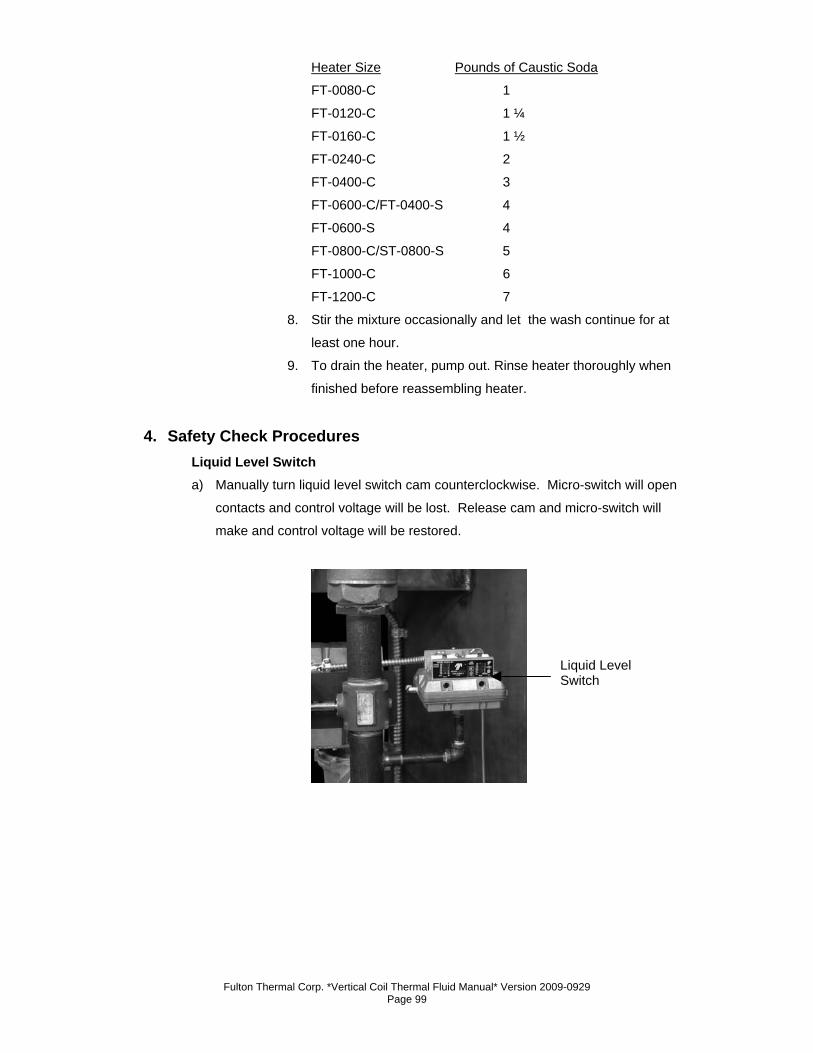
Fulton Thermal Corp. *Vertical Coil Thermal Fluid Manual* Version 2009-0929 Page 99
Heater Size Pounds of Caustic Soda
FT-0080-C 1
FT-0120-C 1 ¼
FT-0160-C 1 ½
FT-0240-C 2
FT-0400-C 3
FT-0600-C/FT-0400-S 4
FT-0600-S 4
FT-0800-C/ST-0800-S 5
FT-1000-C 6
FT-1200-C 7
8. Stir the mixture occasionally and let the wash continue for at
least one hour.
9. To drain the heater, pump out. Rinse heater thoroughly when
finished before reassembling heater.
4. Safety Check Procedures Liquid Level Switch a) Manually turn liquid level switch cam counterclockwise. Micro-switch will open
contacts and control voltage will be lost. Release cam and micro-switch will
make and control voltage will be restored.
Liquid Level Switch
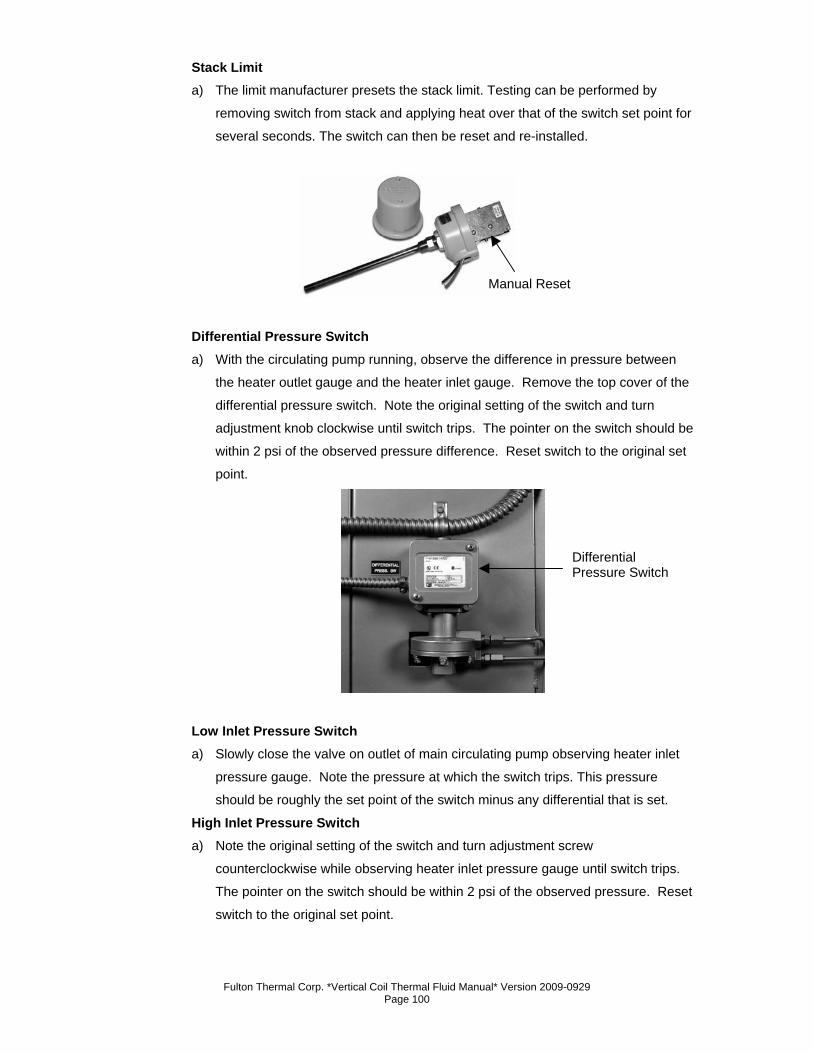
Fulton Thermal Corp. *Vertical Coil Thermal Fluid Manual* Version 2009-0929 Page 100
Stack Limit a) The limit manufacturer presets the stack limit. Testing can be performed by
removing switch from stack and applying heat over that of the switch set point for
several seconds. The switch can then be reset and re-installed.
Differential Pressure Switch a) With the circulating pump running, observe the difference in pressure between
the heater outlet gauge and the heater inlet gauge. Remove the top cover of the
differential pressure switch. Note the original setting of the switch and turn
adjustment knob clockwise until switch trips. The pointer on the switch should be
within 2 psi of the observed pressure difference. Reset switch to the original set
point.
Low Inlet Pressure Switch a) Slowly close the valve on outlet of main circulating pump observing heater inlet
pressure gauge. Note the pressure at which the switch trips. This pressure
should be roughly the set point of the switch minus any differential that is set. High Inlet Pressure Switch a) Note the original setting of the switch and turn adjustment screw
counterclockwise while observing heater inlet pressure gauge until switch trips.
The pointer on the switch should be within 2 psi of the observed pressure. Reset
switch to the original set point.
Manual Reset
Differential Pressure Switch
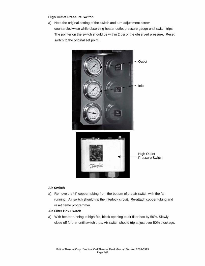
Fulton Thermal Corp. *Vertical Coil Thermal Fluid Manual* Version 2009-0929 Page 101
High Outlet Pressure Switch
a) Note the original setting of the switch and turn adjustment screw
counterclockwise while observing heater outlet pressure gauge until switch trips.
The pointer on the switch should be within 2 psi of the observed pressure. Reset
switch to the original set point.
Air Switch a) Remove the ¼" copper tubing from the bottom of the air switch with the fan
running. Air switch should trip the interlock circuit. Re-attach copper tubing and
reset flame programmer.
Air Filter Box Switch a) With heater running at high fire, block opening to air filter box by 50%. Slowly
close off further until switch trips. Air switch should trip at just over 50% blockage.
Outlet
Inlet
High Outlet Pressure Switch
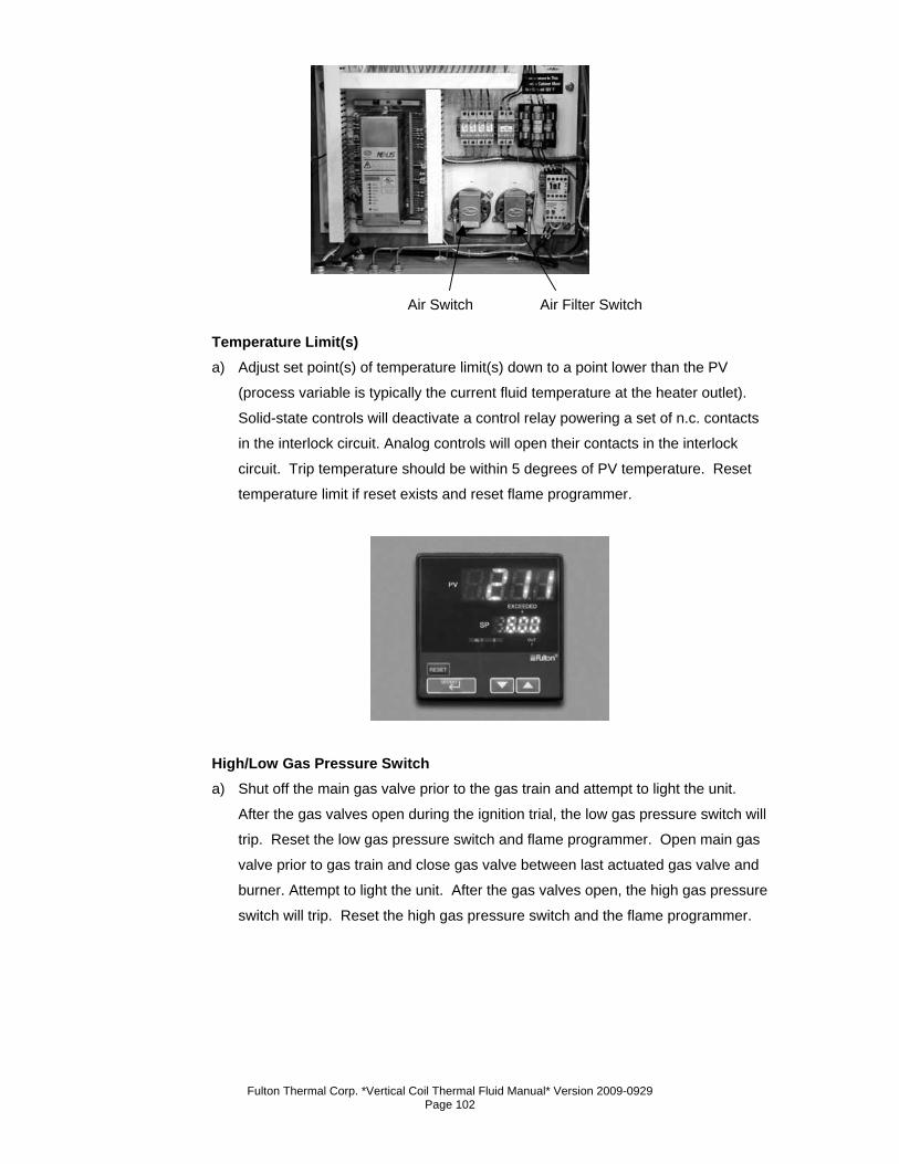
Fulton Thermal Corp. *Vertical Coil Thermal Fluid Manual* Version 2009-0929 Page 102
Temperature Limit(s) a) Adjust set point(s) of temperature limit(s) down to a point lower than the PV
(process variable is typically the current fluid temperature at the heater outlet).
Solid-state controls will deactivate a control relay powering a set of n.c. contacts
in the interlock circuit. Analog controls will open their contacts in the interlock
circuit. Trip temperature should be within 5 degrees of PV temperature. Reset
temperature limit if reset exists and reset flame programmer.
High/Low Gas Pressure Switch a) Shut off the main gas valve prior to the gas train and attempt to light the unit.
After the gas valves open during the ignition trial, the low gas pressure switch will
trip. Reset the low gas pressure switch and flame programmer. Open main gas
valve prior to gas train and close gas valve between last actuated gas valve and
burner. Attempt to light the unit. After the gas valves open, the high gas pressure
switch will trip. Reset the high gas pressure switch and the flame programmer.
Air Switch Air Filter Switch
Fulton Thermal Corp. *Vertical Coil Thermal Fluid Manual* Version 2009-0929 Page 103
5. Recommended Maintenance Schedule (See log sheet) Daily a) Complete log-sheet at least once per day. Twice per shift of operation is
recommended. (Log sheet is available from the Fulton Service Department or on
the web at www.fulton.com)
b) Make visual inspection of entire system for leaks. Repair as soon as possible.
c) Note any failures on flame programmer noting fault number, fault code, fault
annunciation, fault hour, fault cycle, and fault time.
d) Check the exhaust for the presence of smoke. If smoke is present, contact Fulton
Service Department (315) 298-7148 or your local Fulton Thermal Representative.
Weekly a) Check inlet gas pressure at beginning of gas train. Appropriately scaled gauge
should be installed to facilitate this.
b) Check last elbow gas pressure at high fire and low fire and compare to Thermal
Combustion Checklist filled out by start up technician. Appropriately scaled
gauge should be installed to facilitate this. Readings should be within 0.2" w.c.
Monthly a) Clean fuel filters.
b) Check blower fan. Clean if necessary.
c) Clean or change air filter if installed.
d) Manually check fluid level in expansion tank.
e) Check operation of all safeties. Contact Fulton service department for
instructions.
f) When the unit is running, disconnect the flame sensor. Heater should shut off on
flame failure immediately (within 3 seconds).
g) Review log sheets and note any deviations from the norm.
h) Drain ½ gal. Of oil from thermal buffer section of DA tank.
Semi-Annually a) Pull burner and inspect for heat stress or soot. Clean or replace if necessary.
b) Inspect pilot tube assembly and ignition electrode. Clean or replace if necessary.
Reset ignition settings to manual specifications.
c) Inspect refractories for cracks. Make sure there are no pieces of refractory loose
on the bottom of the unit. Cracks 1/8" wide can be patched. If cracks are ¼" or
larger, refractories need to be replaced.
d) Review log sheets and note any deviations from the norm.
e) Have combustion checked for efficiency.
f) Check coil for soot buildup. Clean if necessary
Fulton Thermal Corp. *Vertical Coil Thermal Fluid Manual* Version 2009-0929 Page 104
Annually a) Replace ignition electrode.
b) Clean all the strainers in the thermal fluid system.
c) Take a quart sample of thermal fluid and have it analyzed per fluid manufacturers
instructions.
d) Schedule the local representative or factory technician to perform preventative
maintenance on the system.
Note
All of the above maintenance procedures should be completed by trained personnel. Appropriate training and instructions are available from the Fulton Service Department at (315) 298-7148 or your local Fulton Thermal Representative.
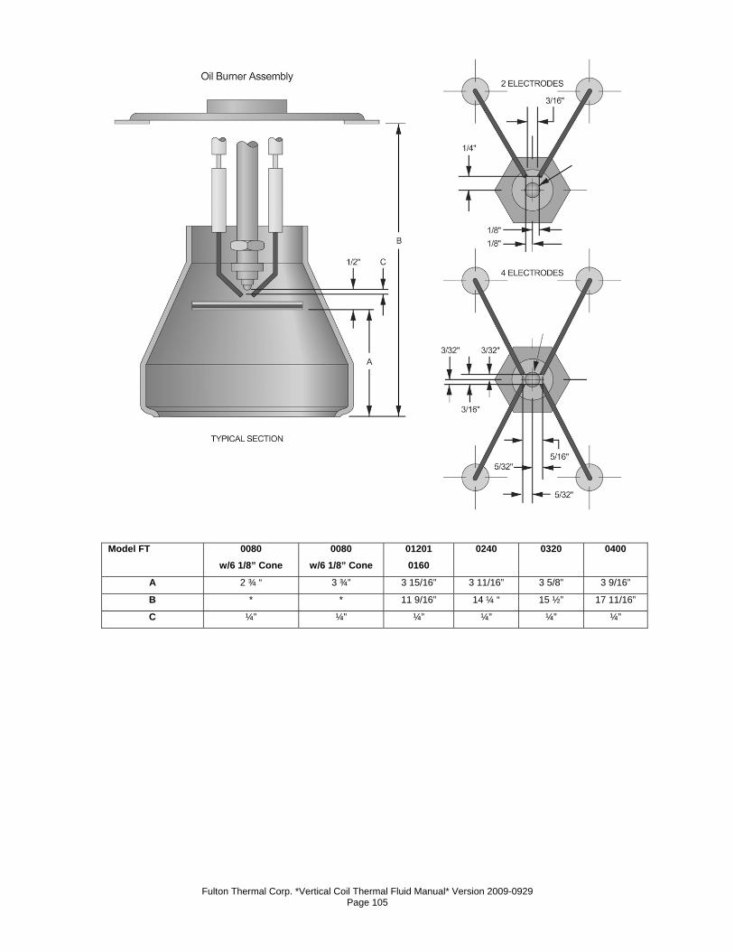
Fulton Thermal Corp. *Vertical Coil Thermal Fluid Manual* Version 2009-0929 Page 105
Model FT 0080
w/6 1/8” Cone 0080
w/6 1/8” Cone 01201 0160
0240
0320 0400
A 2 ¾ “ 3 ¾” 3 15/16” 3 11/16” 3 5/8” 3 9/16”
B * * 11 9/16” 14 ¼ “ 15 ½” 17 11/16”
C ¼” ¼” ¼” ¼” ¼” ¼”
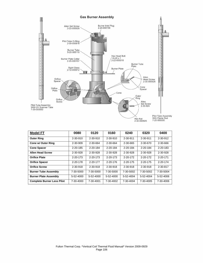
Fulton Thermal Corp. *Vertical Coil Thermal Fluid Manual* Version 2009-0929 Page 106
Model FT 0080 0120 0160 0240 0320 0400 Outer Ring 2-30-910 2-30-910 2-30-910 2-30-911 2-30-911 2-30-912
Cone w/ Outer Ring 2-30-909 2-30-664 2-30-664 2-30-665 2-30-670 2-30-666
Cone Spacer 2-20-185 2-20-184 2-20-184 2-20-184 2-20-184 2-20-183
Allen Head Screw 2-30-928 2-30-928 2-30-928 2-30-928 2-30-928 2-30-928
Orifice Plate 2-20-173 2-20-173 2-20-173 2-20-172 2-20-172 2-20-171
Orifice Spacer 2-20-178 2-20-177 2-20-176 2-20-175 2-20-175 2-20-174
Orifice Screw 2-30-918 2-30-918 2-30-918 2-30-918 2-30-918 2-30-817
Burner Tube Assembly 7-30-5000 7-30-5000 7-30-5000 7-30-5002 7-30-5002 7-30-5004
Burner Plate Assembly 5-52-4000 5-52-4000 5-52-4000 5-52-4004 5-52-4004 5-52-4006
Complete Burner Less Pilot 7-30-4000 7-30-4001 7-30-4002 7-30-4004 7-30-4005 7-30-4006
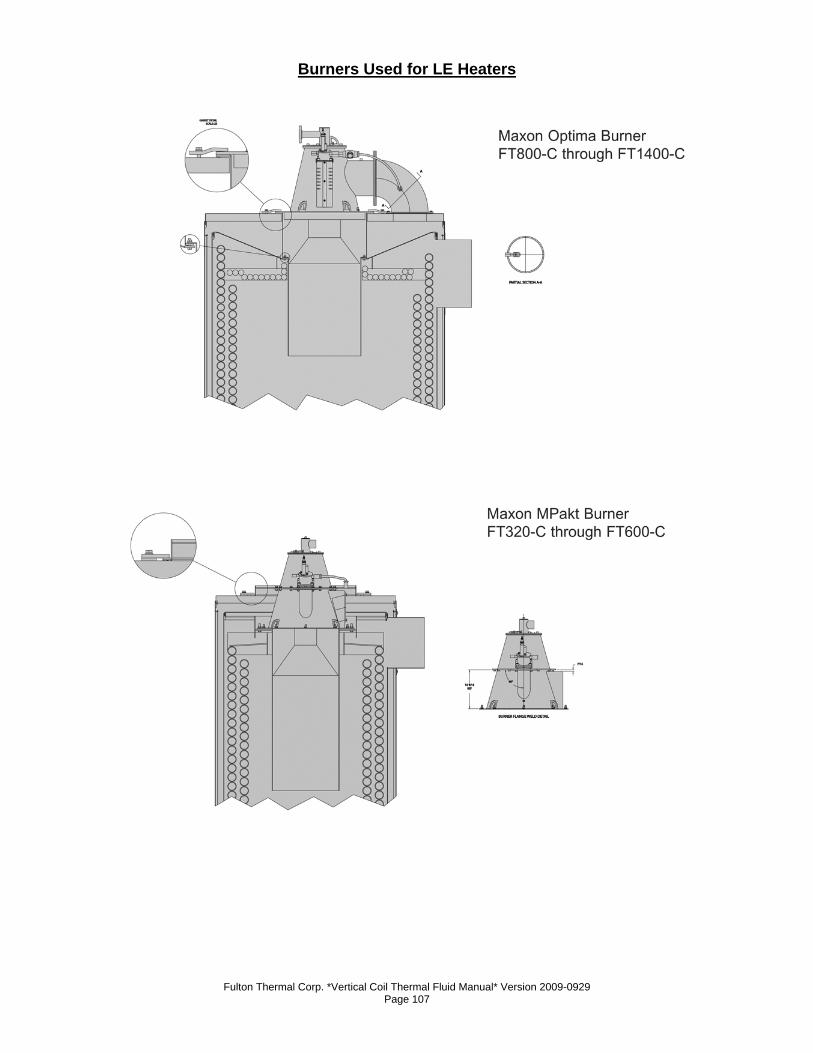
Fulton Thermal Corp. *Vertical Coil Thermal Fluid Manual* Version 2009-0929 Page 107
Burners Used for LE Heaters
Fulton Thermal Corp. *Vertical Coil Thermal Fluid Manual* Version 2009-0929 Page 108
6. Troubleshooting Flow Circuit/Circulating Pump(s)
a) The flow circuit is the electrical circuit that enables the circulating pump(s). Your
thermal fluid pump(s) will remain on until the flow circuit opens to disable the
pump starter or the Off / Pump / Heat switch is turned to the "Off" position.
b) Items in the flow circuit may include paddle type flow switches, a high inlet
pressure switch, a low inlet pressure switch, a high outlet pressure switch and a
differential pressure switch.
c) Low Inlet Pressure Switch
1. All C-Model heaters have a Low Inlet Pressure Switch. This
is a normally open switch that closes with proper heater inlet
pressure. This switch is generally a mercury bulb type
switch. Mercury will rest towards the green cap of the
mercury bulb in a "made" condition.
2. The purpose of the Low Inlet Pressure Switch is primarily to
protect the heater from a low flow condition. The Low Inlet
Pressure Switch should be set at 5 psi below normal heater
inlet pressure as read at operating temperature assuming
that none of the conditions mentioned below are true. A
tripped Low Inlet Pressure Switch is an indication of one of
the following.
3. If your Low Inlet Pressure Switch is not making, check the
following items:
d) Plugged circulation pump strainer basket
1. A plugged strainer will result in a decrease of flow through
the heater. High vacuums developed from plugged strainers
can also stress the seals of the pump causing the pump to
fail.
2. A "Pump Suction" gauge is provided on Fulton Thermal
skids to help determine when a strainer needs cleaning.
Generally this point is between 0 and -5" Hg.
3. If the strainer is plugged, isolate the strainer and drain that
section of piping being mindful of the temperature of the
thermal fluid.
4. Remove the strainer and clean with compressed air, high-
pressure water or a cleaning solution. Replace and observe
new pump suction pressure.
Fulton Thermal Corp. *Vertical Coil Thermal Fluid Manual* Version 2009-0929 Page 109
e) Failed circulation pump coupling
1. A failed coupling will result in a decreased or no flow
condition through the heater. The coupling can be checked
by removing the coupling guard between the pump and
pump motor.
2. The coupling should not be torn or misshapen. If the
coupling needs to be replaced, it is recommended to re-align
the circulating pump first at ambient temperature and again
when it's at operating temperature. Alignment should be
within pump manufacturers' specifications.
f) Cavitation of the circulating pump
1. Cavitation occurs when a pump experiences a loss of head
or if any low heater flashes to gas at the impeller. During this
time, the pump impeller spins without actually circulating any
thermal fluid.
2. If Fulton Thermal Corporation provided the heater skid, loss
of head to the pump is extremely unlikely with proper fluid
level in the combination tank.
3. The most common low heater in a thermal piping system is
water, which needs to be boiled out at startup or anytime
new piping or fluid is added to the thermal oil system.
4. Once the system has been brought up to full operating
temperature, assuming that the entire system has seen flow,
there should be no further occurrence of low heater
contamination apart from possible heat exchanger failure.
g) System is Open
1. Lack of back-pressure. If control valving is improper or pressure
drop across the system is too low, the resulting minimal back-
pressure may not provide enough resistance for the flow to make
the pressure switch. Check the thermal fluid system for proper
operation of control valves.
h) Blocked sensing line on pressure switch
1. A blocked sensing line will give an inaccurate pressure
reading to the pressure switch. A blocked line will need to be
replaced or cleaned. Most installations have block valves at
the heater to facilitate safe isolation and cleaning of the
sensing line.
Fulton Thermal Corp. *Vertical Coil Thermal Fluid Manual* Version 2009-0929 Page 110
i) Improper switch setting
1. The Low Inlet Pressure Switch should be set at 5 psi less
than the pressure read on the heater inlet pressure gauge at
full operating temperature of the system.
j) Faulty Switch
1. If pressure is verified and reads correctly above set point on
switch and the sensing line to the pressure switch is open, the
pressure switch is faulty. Replace switch, set for desired set
point and test for proper operation.
k) High Outlet Pressure Switch
1. All C-Model heaters have a High Outlet Pressure Switch. This is
a normally closed switch that opens with excessive heater outlet
pressure.
2. This switch is generally a mercury bulb type switch. Mercury will
rest towards the green cap in a "made" condition.
3. The purpose of the High Outlet Pressure Switch is primarily to
protect the heater from building too much pressure. Typical coil
model heaters have a maximum working pressure of 150 psi with
100 psi safety valve(s) on the heater outlet manifold.
4. The High Outlet Pressure Switch should be set at 5 psi over the
heater outlet pressure as read at ambient temperature assuming
that none of the conditions mentioned below are true.
5. A tripped High Outlet Pressure Switch is an indication of one of
the following and will require the manual reset button on the
switch to be pushed:
l) An obstruction downstream of the heater
1. Any obstruction downstream of the heater will increase the
pressure that the heater outlet sees. This obstruction will
generally result from an improper valve setting.
2. Observe heater outlet pressure at temperature with all users /
heat exchangers calling for heat (100% user). Observe heater
outlet pressure at temperature with all users / heat exchangers
not calling for heat (100% bypass). Bypass regulating valve(s)
should be adjusted to equal flow condition through users.
3. Call or e-mail Fulton for further details. It may be possible that an
automatic control valve has failed. If this is the case, the valve
actuator should be inspected and possibly replaced.
Fulton Thermal Corp. *Vertical Coil Thermal Fluid Manual* Version 2009-0929 Page 111
m) Improper switch setting
1. The High Outlet Pressure Switch should be set at 5 psi over than
the maximum pressure read on the heater outlet pressure gauge
during proper operation at the coldest ambient temperature
expected.
n) Faulty Switch
1. If pressure is verified and reads correctly below set point on
switch and the sensing line to the pressure switch is open, the
pressure switch is faulty. Replace switch, set for desired set
point and test for proper operation.
o) Flow Switches
1. Units older than mid-1993 have Flow Switches on the inlet of
each pipe in the coil. These are normally open switches that
close, making a micro-switch, upon flow establishment.
2. The purpose of the Flow Switch(es) is to protect the heater coil
from too high of a temperature and to protect the thermal fluid
from exceeding its maximum film temperature. Each flow switch
is wired in series requiring flow through each pipe in the coil.
Flow Switches Not Making a) An obstruction downstream of the Flow Switch(es)
1. Any obstruction downstream of the flow switch(es) will increase
the pressure that the heater outlet sees. Any increase in outlet
pressure will result in diminished flow. This obstruction will
generally result from an improper valve setting.
2. Observe heater outlet pressure at temperature with all users /
heat exchangers calling for heat (100% user). Observe heater
outlet pressure at temperature with all users / heat exchangers
not calling for heat (100% bypass).
3. Bypass regulating valve(s) should be adjusted to equal flow
condition through users. Call or e-mail Fulton for further details.
4. It may be possible that an automatic control valve has failed. If
this is the case, the valve should be replaced.
b) Plugged circulation pump strainer basket
1. A plugged strainer will result in a decrease in flow through the
heater. High vacuums developed from plugged strainers can
also stress the seals of the pump causing the pump to fail.
2. A "Pump Suction" gauge is provided on Fulton Thermal skids to
help determine when a strainer needs cleaning. Generally this
point is -2 psi (5 in. Hg).
Fulton Thermal Corp. *Vertical Coil Thermal Fluid Manual* Version 2009-0929 Page 112
3. If the strainer is plugged, isolate the strainer and drain being
mindful of the temperature of the thermal fluid. Remove the
strainer and clean with compressed air, high-pressure water or a
cleaning solution. Replace and observe new heater inlet
pressure.
c) Failed circulation pump coupling
1. A failed coupling will result in a decreased or no flow condition
through the heater. The coupling can be checked by removing
the coupling guard between the pump and pump motor. The
coupling should not be torn or misshapen. If the coupling needs
to be replaced, it will be necessary to re-align the circulating
pump first at ambient temperature and again when it's at
operating temperature.
d) Cavitation of the circulating pump
1. Cavitation occurs when a partial vacuum presents itself at the
eye of the pump impeller due to loss of head or if any low heater
flashes to gas at the impeller.
2. During this time, the pump impeller spins without actually
circulating any thermal fluid. If Fulton Thermal Corporation
provided the heater skid, loss of head to the pump is extremely
unlikely with proper fluid level in the tank.
3. The most common low heater in a thermal piping system is
water, which needs to be boiled out at startup.
4. Once the system has been brought up to full operating
temperature, assuming that the entire system has seen flow,
there should be no further occurrence of low heater
contamination apart from heat exchanger failure.
e) Plugged coil pipe(s)
1. If too low of a flow condition has occurred for too long a period of
time or if the maximum operating temperature of the oil has been
exceeded, it is possible, however unlikely, that a pipe or pipes in
the coil could plug with solids. If this occurs, it will be necessary
to shut down the system and clean the coil. Fulton Thermal
Corporation should be consulted in this matter.
f) High inlet pressure switch
1. Units newer than mid-1993 have a High Inlet Pressure Switch.
This is a normally closed switch that opens with improper heater
inlet pressure.
Fulton Thermal Corp. *Vertical Coil Thermal Fluid Manual* Version 2009-0929 Page 113
2. This switch is generally a mercury bulb type switch. Mercury will
rest towards the green cap in a "made" condition. The purpose of
the High Inlet Pressure Switch is to protect the heater from
building too high of a pressure.
3. Typical coil model heaters have a maximum working pressure of
150 psi with 100 psi safety valve(s) on the heater outlet manifold.
The High Outlet Pressure Switch should be set at 5 psi over the
heater outlet pressure as read at ambient temperature assuming
that none of the conditions mentioned below are true.
Tripped High Outlet Pressure Switch a) An obstruction downstream of the heater
1. Any obstruction downstream of the heater will increase the
pressure that the heater outlet sees. This obstruction will
generally result from an improper valve setting.
2. Observe heater outlet pressure at temperature with all users /
heat exchangers calling for heat (100% user). Observe heater
outlet pressure at temperature with all users / heat exchangers
not calling for heat (100% bypass).
3. Bypass regulating valve(s) should be adjusted to equal flow
condition through users. Call or e-mail Fulton for further details.
4. It may be possible that an automatic control valve has failed. If
this is the case, the valve should be replaced.
b) Plugged coil pipe(s)
1. If too low of a flow condition has occurred for too long a period of
time or if the maximum operating temperature of the oil has been
exceeded, it is possible, however unlikely, that a pipe or pipes in
the coil could plug with solids. If this occurs, it will be necessary
to shut down the system and clean the coil. Fulton Thermal
Corporation should be consulted in this matter.
c) Improper switch setting
1. The High Inlet Pressure Switch should be set at ambient
temperature. The setting should be 5 psi over than the maximum
pressure read on the heater outlet pressure gauge during proper
operation.
d) Differential Pressure Switch
1. Units newer than mid-1993 have a Differential Pressure Switch.
This is a normally open diaphragm switch that closes with a
proper heater differential pressure between the heater inlet and
outlet.
Fulton Thermal Corp. *Vertical Coil Thermal Fluid Manual* Version 2009-0929 Page 114
2. The purpose of the Differential Pressure Switch is to protect the
heater coil from too high of a temperature and to protect the
thermal fluid from exceeding its maximum film temperature. Each
heater model number has a specific minimum differential
pressure.
3. See Section 1 if you do not know this pressure. This pressure is
the difference in pressure between the heater inlet pressure
gauge and the heater outlet pressure gauge.
Differential Pressure Switch Break a) An obstruction downstream of the heater outlet
1. Any obstruction downstream of the flow switch(es) will increase
the pressure that the heater outlet sees. Any increase in outlet
pressure will result in diminished flow. This obstruction will
generally result from an improper valve setting.
2. Observe heater outlet pressure at temperature with all users /
heat exchangers calling for heat (100% user). Observe heater
outlet pressure at temperature with all users / heat exchangers
not calling for heat (100% bypass).
3. Bypass regulating valve(s) should be adjusted to equal flow
condition through users. Call or e-mail Fulton for further details.
4. It may be possible that an automatic control valve has failed. If
this is the case, the valve should be replaced.
b) Plugged circulation pump strainer basket
1. A plugged strainer will result in a decrease in flow through the
heater. High vacuums developed from plugged strainers can
also stress the seals of the pump causing the pump to fail.
2. A "Pump Suction" gauge is provided on Fulton Thermal skids to
help determine when a strainer needs cleaning. Generally this
point is 5-10 psi (10-20 in. Hg).
3. If the strainer is plugged, isolate the strainer and drain being
mindful of the temperature of the thermal fluid. Remove the
strainer and clean with compressed air, high-pressure water or a
cleaning solution. Replace and observe new heater inlet
pressure.
c) Failed circulation pump coupling
1. A failed coupling will result in a decreased or no flow condition
through the heater. The coupling can be checked by removing
the coupling guard between the pump and pump motor. The
coupling should not be torn or misshapen. If the coupling needs
Fulton Thermal Corp. *Vertical Coil Thermal Fluid Manual* Version 2009-0929 Page 115
to be replaced, it will be necessary to re-align the circulating
pump first at ambient temperature and again when it's at
operating temperature.
d) Cavitation of the circulating pump
1. Cavitation occurs when a partial vacuum presents itself at the
eye of the pump impeller due to loss of head or if any low heater
flashes to gas at the impeller. During this time, the pump impeller
spins without actually circulating any thermal fluid.
2. If Fulton Thermal Corporation provided the heater skid, loss of
head to the pump is extremely unlikely with proper fluid level in
the tank. The most common low heater in a thermal piping
system is water, which needs to be boiled out at startup.
3. Once the system has been brought up to full operating
temperature, assuming that the entire system has seen flow,
there should be no further occurrence of low heater
contamination apart from heat exchanger failure.
e) Plugged coil pipe(s)
1. If too low of a flow condition has occurred for too long a period of
time or if the maximum operating temperature of the oil has been
exceeded, it is possible, however unlikely, that a pipe or pipes in
the coil could plug with solids.
2. If this occurs, it will be necessary to shut down the system and
clean the coil. Fulton Thermal Corporation should be consulted
in this matter.
f) Improper switch setting
1. The Differential Pressure Switch should be set at operating
temperature. The setting should be 2 psi below the minimum
differential pressure for that particular heater model number. If
the minimum required pressure is not known, compare model of
heater to chart on page 1-x of this manual.
Call For Heat a) The call for heat circuit is the circuit that enables burner operation. Fulton
Thermal Corporation has used a variety of Temperature Controllers to act as the
Call for Heat.
b) Generally these controls work in combination with a control relay. When the
Temperature Controller calls for heat, a signal is sent to the coil of a control relay
that closes a normally open set of contacts in series with the burner circuit.
Fulton Thermal Corp. *Vertical Coil Thermal Fluid Manual* Version 2009-0929 Page 116
c) When the call for heat is met, the signal is removed and the contacts return to
their open state. Situations that may interfere with the Call for Heat circuit include
the following:
1. Programming problem
a. Fulton has a general program for each of the
temperature controllers we have used over the years.
Compare your current temperature controller program to
Fulton's general program.
b. See the back of this section for general programming
sheets for standard Fulton heaters.
c. Make changes as necessary. Contact Fulton service
department with any questions.
2. Temperature controller failure
a. If the temperature controller is calling for heat but is not
putting power on the output to the control relay, the relay
will not close the normally open contacts and the heater
will remain disabled. If this is the case, some controllers
have separate sets of contacts that may be utilized in
replacement of the damaged contacts. Some rewiring
and/or reprogramming will be needed. Contact Fulton
service department if necessary.
3. Temperature sensor failure
a. Different temperature controllers use different types of
temperature sensors. These may be Type J
thermocouples, mercury bulbs, RTDs or another type of
sensor. It is possible for these sensors to malfunction.
To verify proper sensor operation, use an alternate
source of temperature detection such as an infra-red
temperature sensor to sense temperature at the same
point.
4. Control relay may have failed
a. Many temperature controllers energize a relay with a call
for heat that in turn closes a normally open set of
contacts to energize the burner circuit.
b. If your temperature controller is sending an output signal
to the control relay but the burner does is not initiated,
check resistance across coil of the relay. An open
reading indicates that the relay needs to be replaced.
If the coil shows resistance, energize coil and check
Fulton Thermal Corp. *Vertical Coil Thermal Fluid Manual* Version 2009-0929 Page 117
contacts. With coil energized, normally open contacts
should close resulting in a reading of control voltage on
both the common and normally open contact.
c. If voltage exists on common but not on normally open
contact either switch contacts if another set of normally
open contacts are available or replace relay.
Burner Interlock a) The burner interlock is the electrical circuit that enables the flame programmer.
Your thermal heater needs to have the items in the burner interlock 'made' before
ignition can occur. Items in the burner interlock may include an air switch, air filter
switch, auxiliary blower motor starter contacts, high temperature limit(s), high gas
pressure switch, low gas pressure switch, and / or low oil pressure switch.
b) Air Switch
1. All C-model heaters have an Air Switch. This is a normally open
switch that closes with proper burner fan outlet pressure. This
switch is generally a diaphragm type switch.
2. The Air Switch is a safety device that proves that there is an
adequate pressure and volume of make up air for proper
combustion and mixing. There is no manual reset on the air
switch itself to indicate a trip. The most likely time of an air switch
trip is at low fire purge or low fire. If this switch trips, it is
generally one of the following issues.
c) The combustion blower fan is dirty
1. If the cups of the squirrel cage type fan become dirty, less air will
be moved by the fan. If the fans are dirty enough, there will not
be enough air flow for the air switch to prove. You should assure
that the combustion blower fan is clean, reset the flame
programmer and try to light unit again.
d) The sensing line is plugged, crimped or pointing in the wrong area
1. If the sensing line to the air switch is crimped or blocked, the
switch will not sense the proper pressure. Ensure that the
sensing line is clear and not crimped by removing both sides of
the sensing line and using compressed air to blow through the
line. Also ensure that the elbow acting as an air scoop is pointing
directly into the air stream. Reset the flame programmer and try
to light the unit again.
e) The switch setting is improper
1. The adjustment screw for the air switch is located opposite the
electrical connections. A gray cap covers the screw. Turn the
Fulton Thermal Corp. *Vertical Coil Thermal Fluid Manual* Version 2009-0929 Page 118
screw clockwise to increase setting, counter-clockwise to
decrease setting. To set switch, run unit at low fire. Increase
setting 1/2 turn every 5 seconds until unit trips on interlock.
Decrease setting by 2 full turns. Reset unit.
f) Air Filter Switch
1. C-model heaters with an air filter box or ducted supply air have
an Air Filter Switch. This is a normally closed switch that opens
on too high of a suction pressure at the burner fan inlet. This
switch is generally a diaphragm type switch.
2. The Air Filter Switch is a safety device that proves that there is
not too negative of a pressure at the combustion blower inlet.
This switch is only used on units that have a built in air box for
use as a duct connection or air filtering device.
3. There is no manual reset on the air filter switch itself to indicate a
trip. The most likely time of an air filter switch trip is at high fire
purge or high fire. If this switch trips, it is generally one of the
following issues.
g) The air filter is dirty
1. If the air filter becomes dirty, the fan will generate greater
suction. Too much suction will result in not enough airflow for
proper combustion and mixing and will cause air switch to trip.
You should regularly change filters on a schedule dependent on
how dirty the makeup air is. After checking or changing air filter,
reset the flame programmer and try to light unit again.
h) There is an obstruction in the make-up air ducting
1. Units that have make-up air ducting need to assure that
blockage to the ducting does not occur. Check outside
termination and any bends in the ducting for blockage. Clear
blockage, reset flame programmer and try to light unit again.
i) The sensing line is pointing in the wrong area
1. The sensing line for the air filter switch is supposed to provide
the static pressure of the air box. The termination of the sensing
line should be pointing in a direction that limits its contact with
moving air.
2. If the sensing line is pointing perpendicularly to entering air
stream, the switch will not sense the proper pressure and could
give a false indication of air box suction. Reset the flame
programmer and try to light the unit again.
Fulton Thermal Corp. *Vertical Coil Thermal Fluid Manual* Version 2009-0929 Page 119
j) The switch setting is improper
1. The adjustment screw for the air switch is located opposite the
electrical connections. A gray cap covers the screw. Turn the
screw clockwise to increase setting, counterclockwise to
decrease setting. The switch setting should be set in such a way
that with 50% of the air box opening blocked, the switch will trip.
Reset switch setting, reset the flame programmer and try to light
the unit again.
k) Auxiliary Blower Motor Starter
1. All C-model heaters use an auxiliary set of contacts on their
blower motor starter to prove that the burner motor is latched on.
This is a normally open set of contacts mounted on or built in to
the blower motor starter.
2. The Auxiliary Blower Motor Contacts are a safety device that
proves that the blower motor starter is latched in. These contacts
work in redundancy to the air switch to prove that there is proper
makeup air. There is no manual reset on the auxiliary contacts
themselves to indicate a trip. If the contacts do not make, it is
generally one of the following issues.
l) The blower motor starter coil is bad
1. If this is the case, the blower starter will not latch in. Check for
voltage to the coil. If proper voltage is present and the starter
does not pull in, that proves the coil is bad. Replace the starter,
reset the flame programmer and try to light unit again.
m) The auxiliary contacts are burned or pitted
1. Visibly inspect contacts. With power off, attempt to clean or
replace starter if damaged. Reset flame programmer and try to
light unit again.
n) High temperature limit
1. All thermal fluid heaters have at least one High Temperature
Limit. The high temperature limit(s) is/are normally closed
switch(es) that break on a temperature rise over set point.
2. The switch may be either a solid state controller or a bulb and
capillary type switch. The High Temperature Limit is a safety
device that protects the thermal fluid and heat transfer coil from
excessively high temperatures.
3. Solid-state high temperature limits will have a manual reset. Bulb
and capillary type limits will not have a manual reset. If this/these
switch(es) trips, it is generally one of the following issues.
Fulton Thermal Corp. *Vertical Coil Thermal Fluid Manual* Version 2009-0929 Page 120
o) Flow rate is too low
1. Too low of a flow rate will result in a higher rate of heat transfer
to the thermal fluid and heat transfer coils. This will result in a
higher temperature difference between inlet temperature and
outlet temperature.
2. It is important to make sure that the minimum flow rate as
specified by Fulton for that specific model is maintained.
3. Check inlet and outlet pressures of the heater to determine
differential pressure and flow rate. Ensure that this flow rate
meets or exceeds minimums specified by Fulton (see chart).
Also check differential pressure switch for proper operation and
setting.
p) The heater is over-fired
1. If the heater has more fuel input than design, it is probable that
the heat transfer rate will increase beyond design.
Check input to heater at high fire for modulated heaters or at the
standard rate for on / off units. This can be done by either using
a corrected gas meter reading or measuring gas pressure
supplied to the burner compared to factory test-fire settings.
2. If input is improper, inspect burner as described below. If burner
is not damaged or have improper components, adjust fuel input
and combustion to specification.
q) Gas-fired burner is damaged
1. Pull and inspect the burner. Primary areas of concern for gas-
fired units are the orifice plate, pilot assembly seating and orifice
plate gap.
2. If the orifice plate is warped or burned through, pilot assembly is
not seated or gap between orifice plate and gas tube is improper,
more fuel than designed for will enter the furnace.
3. This will cuase the heater to have more fuel input than designed
for. The design flow rate will then be too low causing the fluid to
heat up higher than it should.
r) High Gas Pressure Switch
1. All gas-fired modulating or IRI rated thermal fluid heaters have a
High Gas Pressure Switch. This is a normally closed diaphragm
switch that opens on a pressure increase over set point.
2. The High Gas Pressure Switch is a safety device that protects
the burner from receiving too high of a gas pressure. The switch
Fulton Thermal Corp. *Vertical Coil Thermal Fluid Manual* Version 2009-0929 Page 121
senses this pressure downstream of the last gas valve, upstream
of the modulation valve on units that modulate.
3. This switch is most likely to trip at low fire. If this switch trips, it is
generally one of the following issues.
s) Gas pressure setting on the main regulator is too high
1. With unit running at high fire, make sure that the modulated gas
valve is at full open.
Note
Since unit lights at low fire, it may be necessary to increase high gas pressure setting or jumper contacts to allow unit to modulate to where modulation gas valve back pressure is lessened.
2. Check net last elbow gas pressure and compare to factory test
fire sheet. Net gas pressure is running gas pressure minus p
urge pressure. Make sure net pressure reading is within .2" w.c.
of factory reading. If there is a difference, adjust main regulator.
Adjust for proper combustion throughout range.
t) Low fire gas valve setting is too low
1. Because the sensing point of the High Gas Pressure Switch is
upstream of the modulating gas valve, the highest pressure read
will occur during low fire.
2. Check net last elbow gas pressure and compare to factory test
fire sheet. Net gas pressure is running gas pressure minus purge
pressure. Make sure net pressure reading is within .1" w.c. of
factory reading. If there is a difference, adjust modulating gas
valve linkage. Adjust for proper combustion throughout range.
u) Gas orifice plate is warped
1. If above two items are proper, check the pressure that the high
gas pressure switch is sensing by way of a tee installed in the
line. Hold unit at low fire and check pressure. Setting on switch
should be 10% over pressure read. Call Fulton if you have any
questions.
v) Gas pressure switch setting is improper
1. If above two items are proper, check the pressure that the high
gas pressure switch is sensing by way of a tee installed in the
line. Hold unit at low fire and check pressure. Setting on switch
should be 10% over pressure read. Call Fulton if you have any
questions.
Fulton Thermal Corp. *Vertical Coil Thermal Fluid Manual* Version 2009-0929 Page 122
w) Gas regulator has failed open
1. This is highly unlikely. Regulators will usually fail safe in the
closed position. The gas regulator can be checked by checking
upstream pressure and comparing to downstream pressure.
Make sure that the upstream pressure is not above the rating of
the regulator. Make sure that the downstream pressure does not
exceed the range of the spring. If regulator has failed, replace,
reset input and adjust input throughout the range.
x) Low Gas Pressure Switch
1. All gas-fired modulating or IRI rated thermal fluid heaters have a
Low Gas Pressure Switch. This is a normally closed diaphragm
switch that opens on a pressure decrease below set point.
2. The Low Gas Pressure Switch is a safety device that protects
the burner from receiving too low of a gas pressure. The switch
senses this pressure just downstream of the gas regulator. This
switch will most likely trip at high fire. If this switch trips, it is
generally one of the following issues.
y) Gas pressure setting on the main regulator is too low
1. At high fire, the modulating gas valve is full open resulting in the
least amount of back pressure in the gas train. With unit running
at high fire, check net last elbow gas pressure and compare to
factory test fire sheet. Net gas pressure is running gas pressure
minus purge pressure. Make sure net pressure reading is within
.2" w.c. of factory reading. If there is a difference, adjust main
regulator. Adjust for proper combustion throughout range.
z) Gas orifice plate is damaged
1. If the orifice plate is damaged, it may be holding back less gas
creating a lower pressure on the sensing switch. Pull burner and
inspect gas orifice plate. Plate should in no way be warped or
degraded. If it is, replace. After reinstallation, recheck input and
adjust combustion throughout range.
aa) Gas pressure switch setting is improper
1. If above two items are proper, check the pressure that the low
gas pressure switch is sensing by way of a tee installed in the
line. Hold unit at high fire and check pressure. Setting on switch
should be 10% under pressure read. Call Fulton if you have any
questions.
Fulton Thermal Corp. *Vertical Coil Thermal Fluid Manual* Version 2009-0929 Page 123
bb) Gas regulator has failed closed
1. Regulators will usually fail safe in the closed position. The gas
regulator can be checked by checking upstream pressure and
comparing to downstream pressure. Make sure that the
upstream pressure is not above the rating of the regulator. If
regulator has failed, replace, reset input and adjust input
throughout the range.
cc) Low oil pressure switch
1. All oil fired modulating thermal fluid heaters have a Low Oil
Pressure Switch. This is a normally closed diaphragm switch that
opens on a pressure decrease below set point. The Low Oil
Pressure Switch is a safety device that protects the burner from
receiving too low of an oil pressure. The switch senses this
pressure just downstream of the gas pump. If this switch trips, it
is generally one of the following issues.
dd) Oil pressure setting on the back pressure valve is too low
1. At low fire, the modulating oil valve is at its most open position
resulting in the least amount of back pressure in the fuel train.
With unit running at low fire, check oil pressure and compare to
factory test fire sheet. Make sure oil pressure reading is within 10
psi of factory reading. If there is a difference, adjust back
pressure regulator. Adjust for proper combustion throughout
range.
ee) Fuel oil pump may have lost its prime
1. An air bubble in the pump will result in a momentary loss of
prime that will be enough to cause the Low Oil Pressure Switch
to trip. Ensure that oil pump is primed properly and all
connections are tight. Check the pump seal. A blown seal will
allow air in the pump housing.
ff) Fuel oil pump motor may have failed
1. Check the pump motor for proper voltage. If voltage is proper but
motor does not turn, replace or rebuild motor. If there is no
voltage, check motor starter for input signal and incoming 3-
phase power.
gg) Fuel oil pump coupling may have failed
1. A failed coupling will result in the pump not turning. Check
coupling. Replace if necessary.
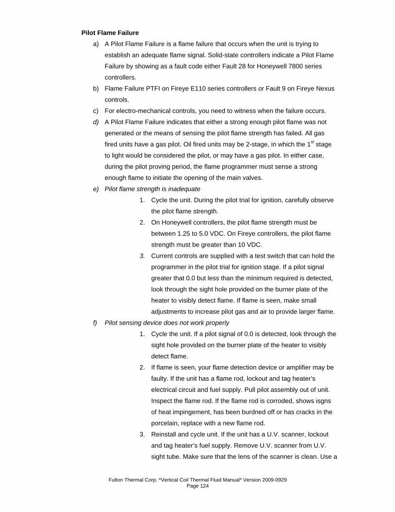
Fulton Thermal Corp. *Vertical Coil Thermal Fluid Manual* Version 2009-0929 Page 124
Pilot Flame Failure a) A Pilot Flame Failure is a flame failure that occurs when the unit is trying to
establish an adequate flame signal. Solid-state controllers indicate a Pilot Flame
Failure by showing as a fault code either Fault 28 for Honeywell 7800 series
controllers.
b) Flame Failure PTFI on Fireye E110 series controllers or Fault 9 on Fireye Nexus
controls.
c) For electro-mechanical controls, you need to witness when the failure occurs.
d) A Pilot Flame Failure indicates that either a strong enough pilot flame was not
generated or the means of sensing the pilot flame strength has failed. All gas
fired units have a gas pilot. Oil fired units may be 2-stage, in which the 1st stage
to light would be considered the pilot, or may have a gas pilot. In either case,
during the pilot proving period, the flame programmer must sense a strong
enough flame to initiate the opening of the main valves.
e) Pilot flame strength is inadequate
1. Cycle the unit. During the pilot trial for ignition, carefully observe
the pilot flame strength.
2. On Honeywell controllers, the pilot flame strength must be
between 1.25 to 5.0 VDC. On Fireye controllers, the pilot flame
strength must be greater than 10 VDC.
3. Current controls are supplied with a test switch that can hold the
programmer in the pilot trial for ignition stage. If a pilot signal
greater that 0.0 but less than the minimum required is detected,
look through the sight hole provided on the burner plate of the
heater to visibly detect flame. If flame is seen, make small
adjustments to increase pilot gas and air to provide larger flame.
f) Pilot sensing device does not work properly
1. Cycle the unit. If a pilot signal of 0.0 is detected, look through the
sight hole provided on the burner plate of the heater to visibly
detect flame.
2. If flame is seen, your flame detection device or amplifier may be
faulty. If the unit has a flame rod, lockout and tag heater’s
electrical circuit and fuel supply. Pull pilot assembly out of unit.
Inspect the flame rod. If the flame rod is corroded, shows isgns
of heat impingement, has been burdned off or has cracks in the
porcelain, replace with a new flame rod.
3. Reinstall and cycle unit. If the unit has a U.V. scanner, lockout
and tag heater’s fuel supply. Remove U.V. scanner from U.V.
sight tube. Make sure that the lens of the scanner is clean. Use a
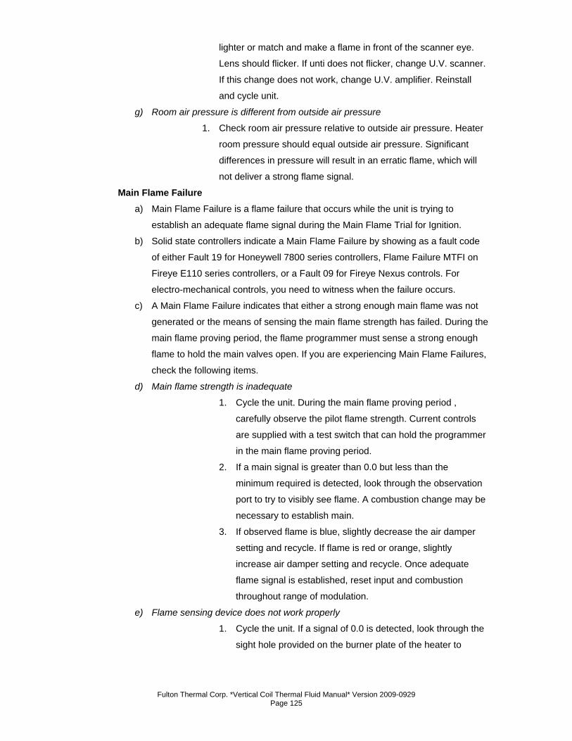
Fulton Thermal Corp. *Vertical Coil Thermal Fluid Manual* Version 2009-0929 Page 125
lighter or match and make a flame in front of the scanner eye.
Lens should flicker. If unti does not flicker, change U.V. scanner.
If this change does not work, change U.V. amplifier. Reinstall
and cycle unit.
g) Room air pressure is different from outside air pressure
1. Check room air pressure relative to outside air pressure. Heater
room pressure should equal outside air pressure. Significant
differences in pressure will result in an erratic flame, which will
not deliver a strong flame signal.
Main Flame Failure a) Main Flame Failure is a flame failure that occurs while the unit is trying to
establish an adequate flame signal during the Main Flame Trial for Ignition.
b) Solid state controllers indicate a Main Flame Failure by showing as a fault code
of either Fault 19 for Honeywell 7800 series controllers, Flame Failure MTFI on
Fireye E110 series controllers, or a Fault 09 for Fireye Nexus controls. For
electro-mechanical controls, you need to witness when the failure occurs.
c) A Main Flame Failure indicates that either a strong enough main flame was not
generated or the means of sensing the main flame strength has failed. During the
main flame proving period, the flame programmer must sense a strong enough
flame to hold the main valves open. If you are experiencing Main Flame Failures,
check the following items.
d) Main flame strength is inadequate
1. Cycle the unit. During the main flame proving period ,
carefully observe the pilot flame strength. Current controls
are supplied with a test switch that can hold the programmer
in the main flame proving period.
2. If a main signal is greater than 0.0 but less than the
minimum required is detected, look through the observation
port to try to visibly see flame. A combustion change may be
necessary to establish main.
3. If observed flame is blue, slightly decrease the air damper
setting and recycle. If flame is red or orange, slightly
increase air damper setting and recycle. Once adequate
flame signal is established, reset input and combustion
throughout range of modulation.
e) Flame sensing device does not work properly
1. Cycle the unit. If a signal of 0.0 is detected, look through the
sight hole provided on the burner plate of the heater to
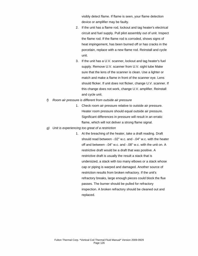
Fulton Thermal Corp. *Vertical Coil Thermal Fluid Manual* Version 2009-0929 Page 126
visibly detect flame. If flame is seen, your flame detection
device or amplifier may be faulty.
2. If the unit has a flame rod, lockout and tag heater's electrical
circuit and fuel supply. Pull pilot assembly out of unit. Inspect
the flame rod. If the flame rod is corroded, shows signs of
heat impingement, has been burned off or has cracks in the
porcelain, replace with a new flame rod. Reinstall and cycle
unit.
3. If the unit has a U.V. scanner, lockout and tag heater's fuel
supply. Remove U.V. scanner from U.V. sight tube Make
sure that the lens of the scanner is clean. Use a lighter or
match and make a flame in front of the scanner eye. Lens
should flicker. If unit does not flicker, change U.V. scanner. If
this change does not work, change U.V. amplifier. Reinstall
and cycle unit.
f) Room air pressure is different from outside air pressure
1. Check room air pressure relative to outside air pressure.
Heater room pressure should equal outside air pressure.
Significant differences in pressure will result in an erratic
flame, which will not deliver a strong flame signal.
g) Unit is experiencing too great of a restriction
1. At the breaching of the heater, take a draft reading. Draft
should read between -.02" w.c. and -.04" w.c. with the heater
off and between -.04" w.c. and -.08" w.c. with the unit on. A
restrictive draft would be a draft that was positive. A
restrictive draft is usually the result a stack that is
undersized, a stack with too many elbows or a stack whose
cap or piping is warped and damaged. Another source of
restriction results from broken refractory. If the unit's
refractory breaks, large enough pieces could block the flue
passes. The burner should be pulled for refractory
inspection. A broken refractory should be cleaned out and
replaced.
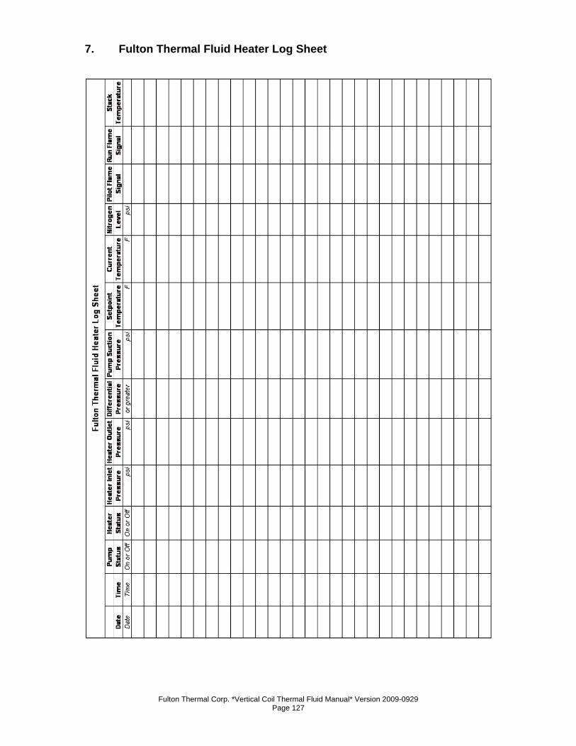
Fulton Thermal Corp. *Vertical Coil Thermal Fluid Manual* Version 2009-0929 Page 127
7. Fulton Thermal Fluid Heater Log Sheet

Fulton Thermal Corp. *Vertical Coil Thermal Fluid Manual* Version 2009-0929 Page 128

Fulton Thermal Corp. *Vertical Coil Thermal Fluid Manual* Version 2009-0929 Page 129
Section 5

Fulton Thermal Corp. *Vertical Coil Thermal Fluid Manual* Version 2009-0929 Page 130
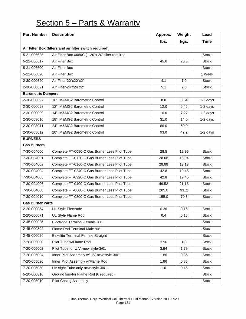
Fulton Thermal Corp. *Vertical Coil Thermal Fluid Manual* Version 2009-0929 Page 131
Section 5 – Parts & Warranty Part Number Description Approx.
lbs. Weight
kgs. Lead Time
Air Filter Box (filters and air filter switch required)
5-21-006625 Air Filter Box-0080C (1-20”x 20” filter required Stock
5-21-006617 Air Filter Box 45.6 20.8 Stock
5-21-006600 Air Filter Box Stock
5-21-006620 Air Filter Box 1 Week
2-30-000620 Air Filter-20”x20”x2” 4.1 1.9 Stock
2-30-000621 Air Filter-24"x24”x2” 5.1 2.3 Stock
Barometric Dampers
2-30-000097 10” M&MG2 Barometric Control 8.0 3.64 1-2 days
2-30-000098 12” M&MG2 Barometric Control 12.0 5.45 1-2 days
2-30-000099 14” M&MG2 Barometric Control 16.0 7.27 1-2 days
2-30-003010 18” M&MG2 Barometric Control 31.0 14.0 1-2 days
2-30-003011 24” M&MG2 Barometric Control 66.0 60.0
2-30-003012 28” M&MG2 Barometric Control 93.0 42.2 1-2 days
BURNERS Gas Burners
7-30-004000 Complete FT-0080-C Gas Burner Less Pilot Tube 28.5 12.95 Stock
7-30-004001 Complete FT-0120-C Gas Burner Less Pilot Tube 28.68 13.04 Stock
7-30-004002 Complete FT-0160-C Gas Burner Less Pilot Tube 28.88 13.13 Stock
7-30-004004 Complete FT-0240-C Gas Burner Less Pilot Tube 42.8 19.45 Stock
7-30-004005 Complete FT-0320-C Gas Burner Less Pilot Tube 42.8 19.45 Stock 7-30-004006 Complete FT-0400-C Gas Burner Less Pilot Tube 46.52 21.15 Stock 7-30-004008 Complete FT-0600-C Gas Burner Less Pilot Tube 205.0 93..2 Stock 7-30-004010 Complete FT-0800-C Gas Burner Less Pilot Tube 155.0 70.5 Stock Gas Burner Parts 2-20-000054 UL Style Electrode 0.36 0.16 Stock 2-20-000071 UL Style Flame Rod 0.4 0.18 Stock 2-45-000025 Electrode Terminal-Female 90° Stock 2-45-000392 Flame Rod Terminal-Male 90° Stock 2-45-000026 Bakelite Terminal-Female Straight Stock 7-20-005000 Pilot Tube w/Flame Rod 3.96 1.8 Stock 7-20-005002 Pilot Tube for U.V.-new style-3/01 3.94 1.79 Stock 7-20-005004 Inner Pilot Assembly w/ UV-new style-3/01 1.86 0.85 Stock 7-20-005020 Inner Pilot Assembly w/Flame Rod 1.86 0.85 Stock 7-20-005030 UV sight Tube only-new style-3/01 1.0 0.45 Stock 5-20-000810 Ground fins-for Flame Rod (6 required) Stock 7-20-005010 Pilot Casing Assembly Stock
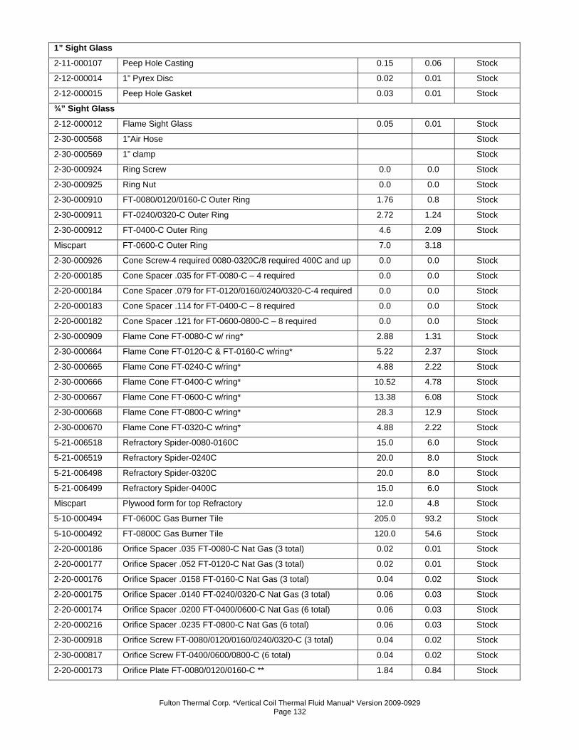
Fulton Thermal Corp. *Vertical Coil Thermal Fluid Manual* Version 2009-0929 Page 132
1” Sight Glass
2-11-000107 Peep Hole Casting 0.15 0.06 Stock 2-12-000014 1” Pyrex Disc 0.02 0.01 Stock 2-12-000015 Peep Hole Gasket 0.03 0.01 Stock ¾” Sight Glass
2-12-000012 Flame Sight Glass 0.05 0.01 Stock 2-30-000568 1”Air Hose Stock 2-30-000569 1” clamp Stock 2-30-000924 Ring Screw 0.0 0.0 Stock 2-30-000925 Ring Nut 0.0 0.0 Stock 2-30-000910 FT-0080/0120/0160-C Outer Ring 1.76 0.8 Stock 2-30-000911 FT-0240/0320-C Outer Ring 2.72 1.24 Stock 2-30-000912 FT-0400-C Outer Ring 4.6 2.09 Stock Miscpart FT-0600-C Outer Ring 7.0 3.18 2-30-000926 Cone Screw-4 required 0080-0320C/8 required 400C and up 0.0 0.0 Stock 2-20-000185 Cone Spacer .035 for FT-0080-C – 4 required 0.0 0.0 Stock 2-20-000184 Cone Spacer .079 for FT-0120/0160/0240/0320-C-4 required 0.0 0.0 Stock 2-20-000183 Cone Spacer .114 for FT-0400-C – 8 required 0.0 0.0 Stock 2-20-000182 Cone Spacer .121 for FT-0600-0800-C – 8 required 0.0 0.0 Stock 2-30-000909 Flame Cone FT-0080-C w/ ring* 2.88 1.31 Stock 2-30-000664 Flame Cone FT-0120-C & FT-0160-C w/ring* 5.22 2.37 Stock 2-30-000665 Flame Cone FT-0240-C w/ring* 4.88 2.22 Stock 2-30-000666 Flame Cone FT-0400-C w/ring* 10.52 4.78 Stock 2-30-000667 Flame Cone FT-0600-C w/ring* 13.38 6.08 Stock 2-30-000668 Flame Cone FT-0800-C w/ring* 28.3 12.9 Stock 2-30-000670 Flame Cone FT-0320-C w/ring* 4.88 2.22 Stock 5-21-006518 Refractory Spider-0080-0160C 15.0 6.0 Stock 5-21-006519 Refractory Spider-0240C 20.0 8.0 Stock 5-21-006498 Refractory Spider-0320C 20.0 8.0 Stock 5-21-006499 Refractory Spider-0400C 15.0 6.0 Stock Miscpart Plywood form for top Refractory 12.0 4.8 Stock 5-10-000494 FT-0600C Gas Burner Tile 205.0 93.2 Stock 5-10-000492 FT-0800C Gas Burner Tile 120.0 54.6 Stock 2-20-000186 Orifice Spacer .035 FT-0080-C Nat Gas (3 total) 0.02 0.01 Stock 2-20-000177 Orifice Spacer .052 FT-0120-C Nat Gas (3 total) 0.02 0.01 Stock 2-20-000176 Orifice Spacer .0158 FT-0160-C Nat Gas (3 total) 0.04 0.02 Stock 2-20-000175 Orifice Spacer .0140 FT-0240/0320-C Nat Gas (3 total) 0.06 0.03 Stock 2-20-000174 Orifice Spacer .0200 FT-0400/0600-C Nat Gas (6 total) 0.06 0.03 Stock 2-20-000216 Orifice Spacer .0235 FT-0800-C Nat Gas (6 total) 0.06 0.03 Stock 2-30-000918 Orifice Screw FT-0080/0120/0160/0240/0320-C (3 total) 0.04 0.02 Stock 2-30-000817 Orifice Screw FT-0400/0600/0800-C (6 total) 0.04 0.02 Stock 2-20-000173 Orifice Plate FT-0080/0120/0160-C ** 1.84 0.84 Stock
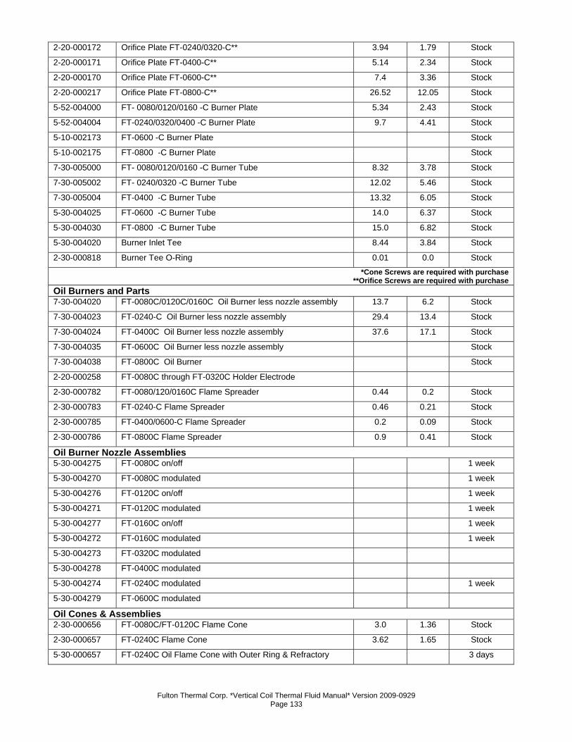
Fulton Thermal Corp. *Vertical Coil Thermal Fluid Manual* Version 2009-0929 Page 133
2-20-000172 Orifice Plate FT-0240/0320-C** 3.94 1.79 Stock 2-20-000171 Orifice Plate FT-0400-C** 5.14 2.34 Stock 2-20-000170 Orifice Plate FT-0600-C** 7.4 3.36 Stock 2-20-000217 Orifice Plate FT-0800-C** 26.52 12.05 Stock 5-52-004000 FT- 0080/0120/0160 -C Burner Plate 5.34 2.43 Stock 5-52-004004 FT-0240/0320/0400 -C Burner Plate 9.7 4.41 Stock 5-10-002173 FT-0600 -C Burner Plate Stock 5-10-002175 FT-0800 -C Burner Plate Stock 7-30-005000 FT- 0080/0120/0160 -C Burner Tube 8.32 3.78 Stock 7-30-005002 FT- 0240/0320 -C Burner Tube 12.02 5.46 Stock 7-30-005004 FT-0400 -C Burner Tube 13.32 6.05 Stock 5-30-004025 FT-0600 -C Burner Tube 14.0 6.37 Stock 5-30-004030 FT-0800 -C Burner Tube 15.0 6.82 Stock 5-30-004020 Burner Inlet Tee 8.44 3.84 Stock 2-30-000818 Burner Tee O-Ring 0.01 0.0 Stock
*Cone Screws are required with purchase **Orifice Screws are required with purchase
Oil Burners and Parts 7-30-004020 FT-0080C/0120C/0160C Oil Burner less nozzle assembly 13.7 6.2 Stock
7-30-004023 FT-0240-C Oil Burner less nozzle assembly 29.4 13.4 Stock
7-30-004024 FT-0400C Oil Burner less nozzle assembly 37.6 17.1 Stock
7-30-004035 FT-0600C Oil Burner less nozzle assembly Stock
7-30-004038 FT-0800C Oil Burner Stock
2-20-000258 FT-0080C through FT-0320C Holder Electrode
2-30-000782 FT-0080/120/0160C Flame Spreader 0.44 0.2 Stock
2-30-000783 FT-0240-C Flame Spreader 0.46 0.21 Stock
2-30-000785 FT-0400/0600-C Flame Spreader 0.2 0.09 Stock
2-30-000786 FT-0800C Flame Spreader 0.9 0.41 Stock
Oil Burner Nozzle Assemblies 5-30-004275 FT-0080C on/off 1 week
5-30-004270 FT-0080C modulated 1 week
5-30-004276 FT-0120C on/off 1 week
5-30-004271 FT-0120C modulated 1 week
5-30-004277 FT-0160C on/off 1 week
5-30-004272 FT-0160C modulated 1 week
5-30-004273 FT-0320C modulated
5-30-004278 FT-0400C modulated
5-30-004274 FT-0240C modulated 1 week
5-30-004279 FT-0600C modulated
Oil Cones & Assemblies 2-30-000656 FT-0080C/FT-0120C Flame Cone 3.0 1.36 Stock
2-30-000657 FT-0240C Flame Cone 3.62 1.65 Stock
5-30-000657 FT-0240C Oil Flame Cone with Outer Ring & Refractory 3 days
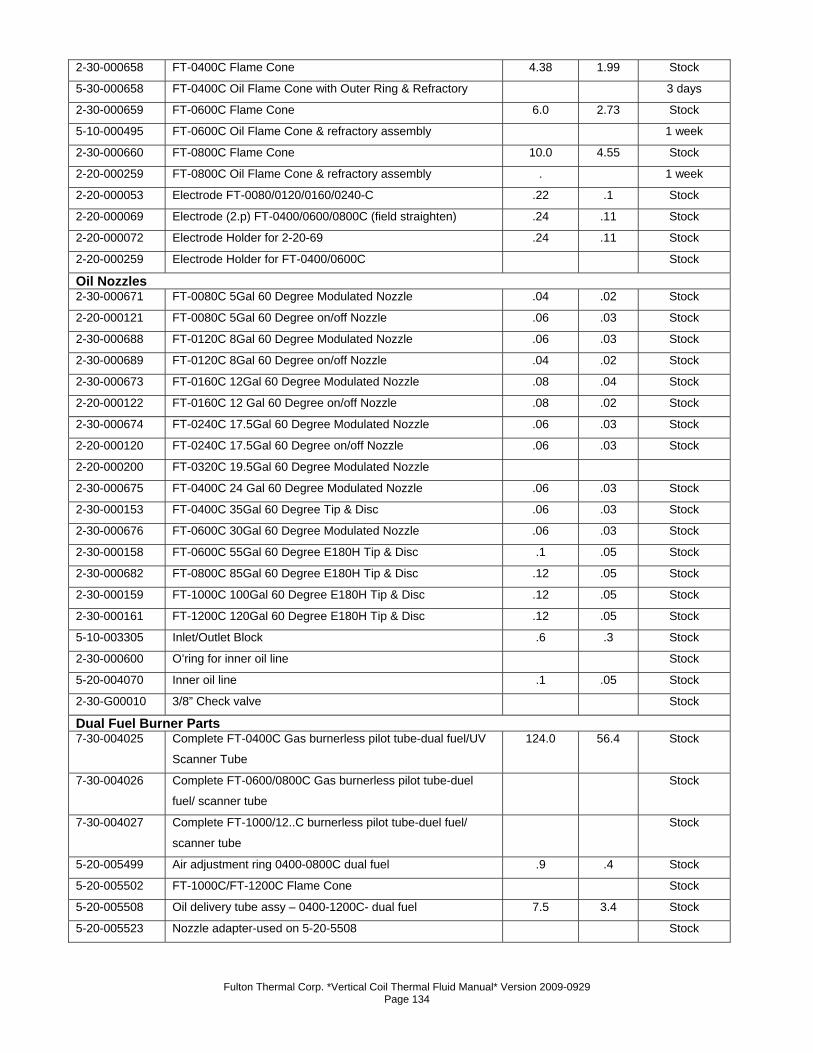
Fulton Thermal Corp. *Vertical Coil Thermal Fluid Manual* Version 2009-0929 Page 134
2-30-000658 FT-0400C Flame Cone 4.38 1.99 Stock
5-30-000658 FT-0400C Oil Flame Cone with Outer Ring & Refractory 3 days
2-30-000659 FT-0600C Flame Cone 6.0 2.73 Stock
5-10-000495 FT-0600C Oil Flame Cone & refractory assembly 1 week
2-30-000660 FT-0800C Flame Cone 10.0 4.55 Stock
2-20-000259 FT-0800C Oil Flame Cone & refractory assembly . 1 week
2-20-000053 Electrode FT-0080/0120/0160/0240-C .22 .1 Stock
2-20-000069 Electrode (2.p) FT-0400/0600/0800C (field straighten) .24 .11 Stock
2-20-000072 Electrode Holder for 2-20-69 .24 .11 Stock
2-20-000259 Electrode Holder for FT-0400/0600C Stock
Oil Nozzles 2-30-000671 FT-0080C 5Gal 60 Degree Modulated Nozzle .04 .02 Stock
2-20-000121 FT-0080C 5Gal 60 Degree on/off Nozzle .06 .03 Stock
2-30-000688 FT-0120C 8Gal 60 Degree Modulated Nozzle .06 .03 Stock
2-30-000689 FT-0120C 8Gal 60 Degree on/off Nozzle .04 .02 Stock
2-30-000673 FT-0160C 12Gal 60 Degree Modulated Nozzle .08 .04 Stock
2-20-000122 FT-0160C 12 Gal 60 Degree on/off Nozzle .08 .02 Stock
2-30-000674 FT-0240C 17.5Gal 60 Degree Modulated Nozzle .06 .03 Stock
2-20-000120 FT-0240C 17.5Gal 60 Degree on/off Nozzle .06 .03 Stock
2-20-000200 FT-0320C 19.5Gal 60 Degree Modulated Nozzle
2-30-000675 FT-0400C 24 Gal 60 Degree Modulated Nozzle .06 .03 Stock
2-30-000153 FT-0400C 35Gal 60 Degree Tip & Disc .06 .03 Stock
2-30-000676 FT-0600C 30Gal 60 Degree Modulated Nozzle .06 .03 Stock
2-30-000158 FT-0600C 55Gal 60 Degree E180H Tip & Disc .1 .05 Stock
2-30-000682 FT-0800C 85Gal 60 Degree E180H Tip & Disc .12 .05 Stock
2-30-000159 FT-1000C 100Gal 60 Degree E180H Tip & Disc .12 .05 Stock
2-30-000161 FT-1200C 120Gal 60 Degree E180H Tip & Disc .12 .05 Stock
5-10-003305 Inlet/Outlet Block .6 .3 Stock
2-30-000600 O’ring for inner oil line Stock
5-20-004070 Inner oil line .1 .05 Stock
2-30-G00010 3/8” Check valve Stock
Dual Fuel Burner Parts 7-30-004025 Complete FT-0400C Gas burnerless pilot tube-dual fuel/UV
Scanner Tube
124.0 56.4 Stock
7-30-004026 Complete FT-0600/0800C Gas burnerless pilot tube-duel
fuel/ scanner tube
Stock
7-30-004027 Complete FT-1000/12..C burnerless pilot tube-duel fuel/
scanner tube
Stock
5-20-005499 Air adjustment ring 0400-0800C dual fuel .9 .4 Stock
5-20-005502 FT-1000C/FT-1200C Flame Cone Stock
5-20-005508 Oil delivery tube assy – 0400-1200C- dual fuel 7.5 3.4 Stock
5-20-005523 Nozzle adapter-used on 5-20-5508 Stock
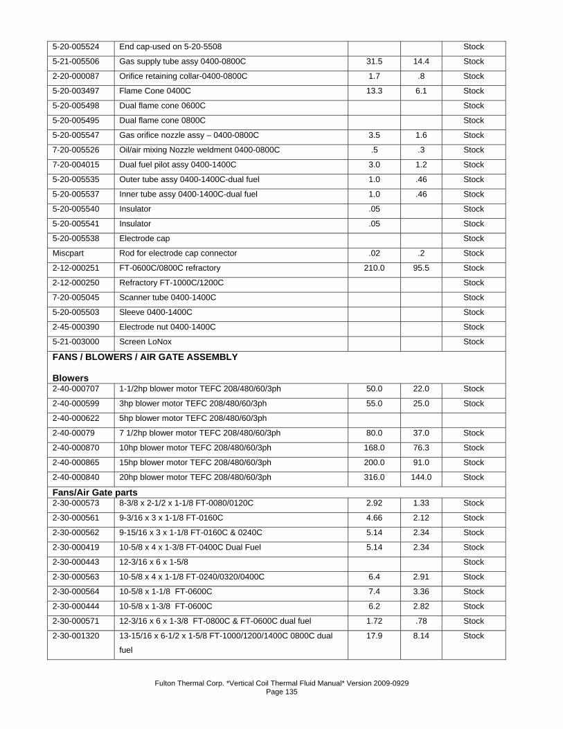
Fulton Thermal Corp. *Vertical Coil Thermal Fluid Manual* Version 2009-0929 Page 135
5-20-005524 End cap-used on 5-20-5508 Stock
5-21-005506 Gas supply tube assy 0400-0800C 31.5 14.4 Stock
2-20-000087 Orifice retaining collar-0400-0800C 1.7 .8 Stock
5-20-003497 Flame Cone 0400C 13.3 6.1 Stock
5-20-005498 Dual flame cone 0600C Stock
5-20-005495 Dual flame cone 0800C Stock
5-20-005547 Gas orifice nozzle assy – 0400-0800C 3.5 1.6 Stock
7-20-005526 Oil/air mixing Nozzle weldment 0400-0800C .5 .3 Stock
7-20-004015 Dual fuel pilot assy 0400-1400C 3.0 1.2 Stock
5-20-005535 Outer tube assy 0400-1400C-dual fuel 1.0 .46 Stock
5-20-005537 Inner tube assy 0400-1400C-dual fuel 1.0 .46 Stock
5-20-005540 Insulator .05 Stock
5-20-005541 Insulator .05 Stock
5-20-005538 Electrode cap Stock
Miscpart Rod for electrode cap connector .02 .2 Stock
2-12-000251 FT-0600C/0800C refractory 210.0 95.5 Stock
2-12-000250 Refractory FT-1000C/1200C Stock
7-20-005045 Scanner tube 0400-1400C Stock
5-20-005503 Sleeve 0400-1400C Stock
2-45-000390 Electrode nut 0400-1400C Stock
5-21-003000 Screen LoNox Stock
FANS / BLOWERS / AIR GATE ASSEMBLY Blowers 2-40-000707 1-1/2hp blower motor TEFC 208/480/60/3ph 50.0 22.0 Stock
2-40-000599 3hp blower motor TEFC 208/480/60/3ph 55.0 25.0 Stock
2-40-000622 5hp blower motor TEFC 208/480/60/3ph
2-40-00079 7 1/2hp blower motor TEFC 208/480/60/3ph 80.0 37.0 Stock
2-40-000870 10hp blower motor TEFC 208/480/60/3ph 168.0 76.3 Stock
2-40-000865 15hp blower motor TEFC 208/480/60/3ph 200.0 91.0 Stock
2-40-000840 20hp blower motor TEFC 208/480/60/3ph 316.0 144.0 Stock
Fans/Air Gate parts 2-30-000573 8-3/8 x 2-1/2 x 1-1/8 FT-0080/0120C 2.92 1.33 Stock
2-30-000561 9-3/16 x 3 x 1-1/8 FT-0160C 4.66 2.12 Stock
2-30-000562 9-15/16 x 3 x 1-1/8 FT-0160C & 0240C 5.14 2.34 Stock
2-30-000419 10-5/8 x 4 x 1-3/8 FT-0400C Dual Fuel 5.14 2.34 Stock
2-30-000443 12-3/16 x 6 x 1-5/8 Stock
2-30-000563 10-5/8 x 4 x 1-1/8 FT-0240/0320/0400C 6.4 2.91 Stock
2-30-000564 10-5/8 x 1-1/8 FT-0600C 7.4 3.36 Stock
2-30-000444 10-5/8 x 1-3/8 FT-0600C 6.2 2.82 Stock
2-30-000571 12-3/16 x 6 x 1-3/8 FT-0800C & FT-0600C dual fuel 1.72 .78 Stock
2-30-001320 13-15/16 x 6-1/2 x 1-5/8 FT-1000/1200/1400C 0800C dual
fuel
17.9 8.14 Stock
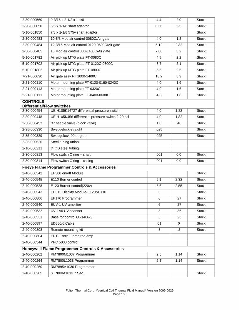
Fulton Thermal Corp. *Vertical Coil Thermal Fluid Manual* Version 2009-0929 Page 136
2-30-000560 9-3/16 x 2-1/2 x 1-1/8 4.4 2.0 Stock
2-20-000050 5/8 x 1-1/8 shaft adaptor 0.56 .25 Stock
5-10-001850 7/8 x 1-1/8 575v shaft adaptor Stock
2-30-000483 10-5/8 Mod air control-0080C/Air gate 4.0 1.8 Stock
2-30-000484 12-3/16 Mod air control 0120-0600C/Air gate 5.12 2.32 Stock
2-30-000485 15 Mod air control 800-1400C/Air gate 7.06 3.2 Stock
5-10-001792 Air pick up MTG plate FT-0080C 4.8 2.2 Stock
5-10-001702 Air pick up MTG plate FT-0120C-0600C 6.7 3.1 Stock
5-10-001802 Air pick up MTG plate FT-0800C 5.5 2.5 Stock
7-21-000030 Air gate assy FT 1000-1400C 18.2 8.3 Stock
2-21-000110 Motor mounting plate FT-0120-0160-0240C 4.0 1.6 Stock
2-21-000113 Motor mounting plate FT-0320C 4.0 1.6 Stock
2-21-000111 Motor mounting plate FT-0400-0600C 4.0 1.6 Stock
CONTROLS Differential/Flow switches 2-30-000454 UE H105K14727 differential pressure switch 4.0 1.82 Stock
2-30-000448 UE H105K456 differential pressure switch 2-20 psi 4.0 1.82 Stock
2-30-000453 ¼” needle valve (block valve) 1.0 .46 Stock
2-35-000330 Swedgelock-straight .025 Stock
2-35-000329 Swedgelock-90 degree .025 Stock
2-35-000526 Steel tubing union
2-10-000211 ¼ OD steel tubing
2-30-000813 Flow switch O’ring – shaft .001 0.0 Stock
2-30-000814 Flow switch O’ring – casing .001 0.0 Stock
Fireye Flame Programmer Controls & Accessories 2-40-000542 EP380 on/off Module Stock
2-40-000545 E110 Burner control 5.1 2.32 Stock
2-40-000528 E120 Burner control(220v) 5.6 2.55 Stock
2-40-000543 ED510 Display Module-E120&E110 .5 Stock
2-40-000806 EP170 Programmer .6 .27 Stock
2-40-000540 EUV-1 UV amplifier .6 .27 Stock
2-40-000532 UV-1A6 UV scanner .8 .36 Stock
2-40-000531 Base for control 60-1466-2 .5 .23 Stock
2-40-000897 ED550/6 Cable .01 0 Stock
2-40-000808 Remote mounting kit .5 .3 Stock
2-40-000804 ERT-1 rect. Flame rod amp 2-40-000544 PPC 5000 control Honeywell Flame Programmer Controls & Accessories 2-40-000262 RM7800M1037 Programmer 2.5 1.14 Stock
2-40-000264 RM7800L1038 Programmer 2.5 1.14 Stock
2-40-000260 RM7895A1030 Programmer
2-40-000265 ST7800A1013 7 Sec. Stock
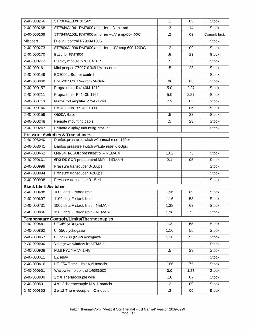
Fulton Thermal Corp. *Vertical Coil Thermal Fluid Manual* Version 2009-0929 Page 137
2-40-000266 ST7800A1039 30 Sec. .1 .05 Stock
2-40-000268 ST7849A1041 RM7800 amplifier – flame rod .3 .14 Stock
2-40-000269 ST7849A1031 RM7800 amplifier –UV amp-80-400C .2 .09 Consult fact.
Miscpart Fuel air control R7999A1005 Stock
2-40-000273 ST7800A1098 RM7800 amplifier – UV amp 600-1200C .2 .09 Stock
2-40-000270 Base for RM7800 .5 .23 Stock
2-40-000272 Display module S7800A1019 .5 .23 Stock
2-40-000161 Mini peeper C7027a1049 UV scanner .5 .23 Stock
2-40-000149 BC7000L Burner control Stock
2-40-000860 PM720L1030 Program Module .06 .03 Stock 2-40-000157 Programmer R4140M-1210 5.0 2.27 Stock 2-40-000711 Programmer R4140L-1162 5.0 2.27 Stock 2-40-000713 Flame rod amplifer R7247A-1005 .12 .05 Stock 2-40-000160 UV amplifier R7249a1003 .1 .05 Stock 2-40-000159 Q520A Base .5 .23 Stock 2-40-000248 Remote mounting cable .5 .23 Stock 2-40-000247 Remote display mounting bracket Stock Pressure Switches & Transducers 2-40-003040 Danfos pressure switch w/manual reset 150psi 2-40-003041 Danfos pressure switch w/auto reset 6-50psi 2-40-000662 6NN54FIA SOR pressuretrol – NEMA 4 1.62 .73 Stock 2-40-000661 6R3-D5 SOR pressuretrol M/R – NEMA 4 2.1 .95 Stock 2-40-000999 Pressure transducer 0-100psi Stock 2-40-000994 Pressure transducer 0-200psi Stock 2-40-000998 Pressure transducer 0-15psi Stock Stack Limit Switches 2-40-000688 1000 deg. F stack limit 1.96 .89 Stock 2-40-000697 1100 deg. F stack limit 1.16 .53 Stock 2-40-000731 1000 deg. F stack limit – NEMA 4 1.38 .63 Stock 2-40-000866 1100 deg. F stack limit – NEMA 4 1.98 .9 Stock Temperature Controls/Limits/Thermocouples 2-40-000861 UT 350 yokogawa 1.2 .55 Stock 2-40-000862 UT350L yokogawa 1.16 .55 Stock 2-40-000867 UT 550-04 (RSP) yokogawa 1.16 .55 Stock 2-30-000900 Yokogawa window kit NEMA-4 Stock 2-40-000909 FUJI PYZ4-RAY-1-4V .5 .23 Stock 2-40-000311 EZ relay Stock 2-40-000816 UE E54 Temp Limit A,N models 1.66 .75 Stock 2-40-000631 Watlow temp control 146E1602 3.0 1.37 Stock 2-40-000800 2 x 8 Thermocouple wire .16 .07 Stock 2-40-000801 4 x 12 thermocouple N & A models .2 .09 Stock 2-40-000802 2 x 12 Thermocouple – C models .2 .09 Stock
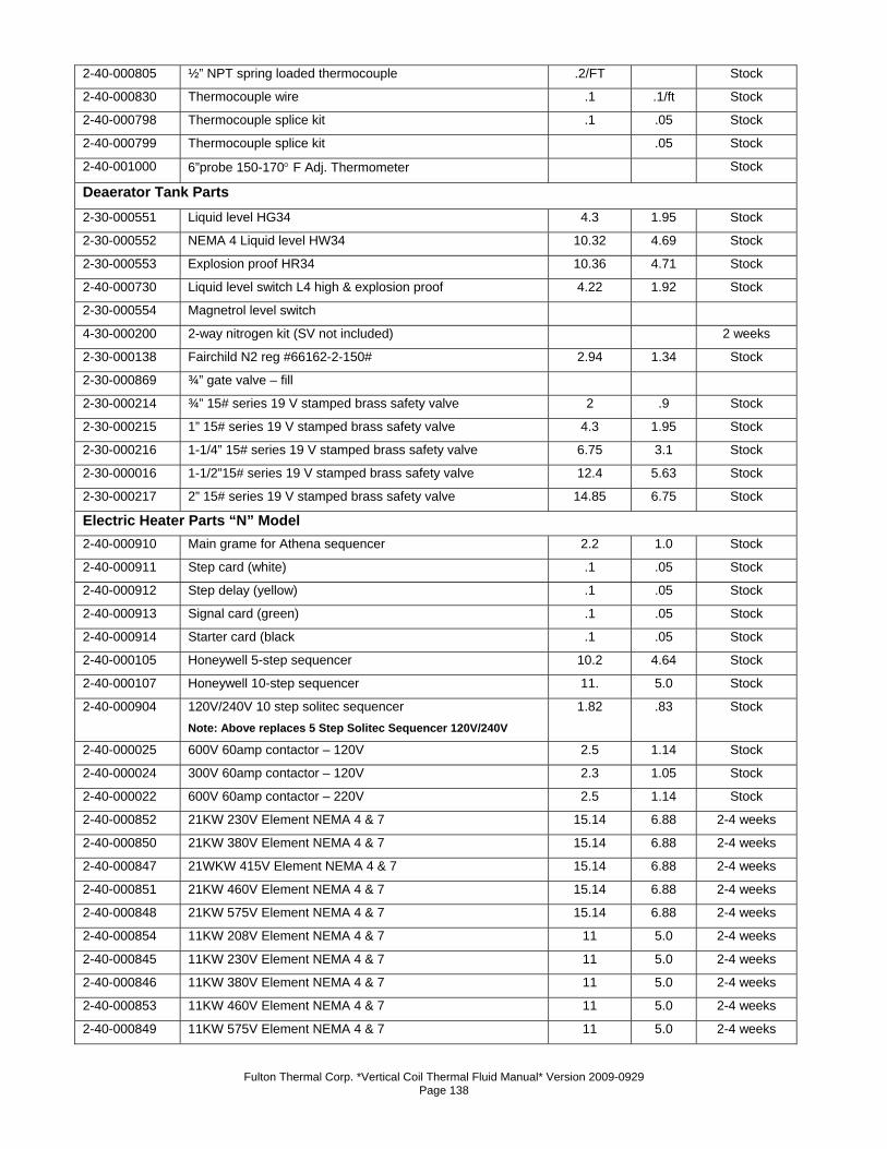
Fulton Thermal Corp. *Vertical Coil Thermal Fluid Manual* Version 2009-0929 Page 138
2-40-000805 ½” NPT spring loaded thermocouple .2/FT Stock 2-40-000830 Thermocouple wire .1 .1/ft Stock 2-40-000798 Thermocouple splice kit .1 .05 Stock 2-40-000799 Thermocouple splice kit .05 Stock 2-40-001000 6”probe 150-170° F Adj. Thermometer Stock Deaerator Tank Parts 2-30-000551 Liquid level HG34 4.3 1.95 Stock 2-30-000552 NEMA 4 Liquid level HW34 10.32 4.69 Stock 2-30-000553 Explosion proof HR34 10.36 4.71 Stock 2-40-000730 Liquid level switch L4 high & explosion proof 4.22 1.92 Stock 2-30-000554 Magnetrol level switch 4-30-000200 2-way nitrogen kit (SV not included) 2 weeks
2-30-000138 Fairchild N2 reg #66162-2-150# 2.94 1.34 Stock
2-30-000869 ¾” gate valve – fill 2-30-000214 ¾” 15# series 19 V stamped brass safety valve 2 .9 Stock 2-30-000215 1” 15# series 19 V stamped brass safety valve 4.3 1.95 Stock 2-30-000216 1-1/4” 15# series 19 V stamped brass safety valve 6.75 3.1 Stock 2-30-000016 1-1/2”15# series 19 V stamped brass safety valve 12.4 5.63 Stock 2-30-000217 2” 15# series 19 V stamped brass safety valve 14.85 6.75 Stock Electric Heater Parts “N” Model 2-40-000910 Main grame for Athena sequencer 2.2 1.0 Stock 2-40-000911 Step card (white) .1 .05 Stock 2-40-000912 Step delay (yellow) .1 .05 Stock 2-40-000913 Signal card (green) .1 .05 Stock 2-40-000914 Starter card (black .1 .05 Stock 2-40-000105 Honeywell 5-step sequencer 10.2 4.64 Stock 2-40-000107 Honeywell 10-step sequencer 11. 5.0 Stock 2-40-000904 120V/240V 10 step solitec sequencer
Note: Above replaces 5 Step Solitec Sequencer 120V/240V
1.82 .83 Stock
2-40-000025 600V 60amp contactor – 120V 2.5 1.14 Stock 2-40-000024 300V 60amp contactor – 120V 2.3 1.05 Stock 2-40-000022 600V 60amp contactor – 220V 2.5 1.14 Stock 2-40-000852 21KW 230V Element NEMA 4 & 7 15.14 6.88 2-4 weeks
2-40-000850 21KW 380V Element NEMA 4 & 7 15.14 6.88 2-4 weeks
2-40-000847 21WKW 415V Element NEMA 4 & 7 15.14 6.88 2-4 weeks
2-40-000851 21KW 460V Element NEMA 4 & 7 15.14 6.88 2-4 weeks
2-40-000848 21KW 575V Element NEMA 4 & 7 15.14 6.88 2-4 weeks
2-40-000854 11KW 208V Element NEMA 4 & 7 11 5.0 2-4 weeks
2-40-000845 11KW 230V Element NEMA 4 & 7 11 5.0 2-4 weeks
2-40-000846 11KW 380V Element NEMA 4 & 7 11 5.0 2-4 weeks
2-40-000853 11KW 460V Element NEMA 4 & 7 11 5.0 2-4 weeks
2-40-000849 11KW 575V Element NEMA 4 & 7 11 5.0 2-4 weeks
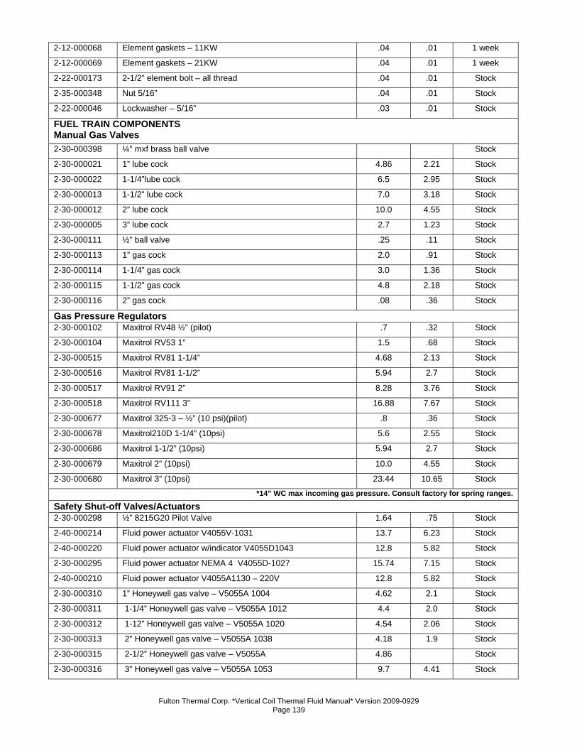
Fulton Thermal Corp. *Vertical Coil Thermal Fluid Manual* Version 2009-0929 Page 139
2-12-000068 Element gaskets – 11KW .04 .01 1 week
2-12-000069 Element gaskets – 21KW .04 .01 1 week
2-22-000173 2-1/2” element bolt – all thread .04 .01 Stock
2-35-000348 Nut 5/16” .04 .01 Stock
2-22-000046 Lockwasher – 5/16” .03 .01 Stock
FUEL TRAIN COMPONENTS Manual Gas Valves 2-30-000398 ¼” mxf brass ball valve Stock
2-30-000021 1” lube cock 4.86 2.21 Stock
2-30-000022 1-1/4”lube cock 6.5 2.95 Stock
2-30-000013 1-1/2” lube cock 7.0 3.18 Stock
2-30-000012 2” lube cock 10.0 4.55 Stock
2-30-000005 3” lube cock 2.7 1.23 Stock
2-30-000111 ½” ball valve .25 .11 Stock
2-30-000113 1” gas cock 2.0 .91 Stock
2-30-000114 1-1/4” gas cock 3.0 1.36 Stock
2-30-000115 1-1/2” gas cock 4.8 2.18 Stock
2-30-000116 2” gas cock .08 .36 Stock
Gas Pressure Regulators 2-30-000102 Maxitrol RV48 ½” (pilot) .7 .32 Stock
2-30-000104 Maxitrol RV53 1” 1.5 .68 Stock
2-30-000515 Maxitrol RV81 1-1/4” 4.68 2.13 Stock
2-30-000516 Maxitrol RV81 1-1/2” 5.94 2.7 Stock
2-30-000517 Maxitrol RV91 2” 8.28 3.76 Stock
2-30-000518 Maxitrol RV111 3” 16.88 7.67 Stock
2-30-000677 Maxitrol 325-3 – ½” (10 psi)(pilot) .8 .36 Stock
2-30-000678 Maxitrol210D 1-1/4” (10psi) 5.6 2.55 Stock
2-30-000686 Maxitrol 1-1/2” (10psi) 5.94 2.7 Stock
2-30-000679 Maxitrol 2” (10psi) 10.0 4.55 Stock
2-30-000680 Maxitrol 3” (10psi) 23.44 10.65 Stock
*14” WC max incoming gas pressure. Consult factory for spring ranges.
Safety Shut-off Valves/Actuators 2-30-000298 ½” 8215G20 Pilot Valve 1.64 .75 Stock
2-40-000214 Fluid power actuator V4055V-1031 13.7 6.23 Stock
2-40-000220 Fluid power actuator w/indicator V4055D1043 12.8 5.82 Stock
2-30-000295 Fluid power actuator NEMA 4 V4055D-1027 15.74 7.15 Stock
2-40-000210 Fluid power actuator V4055A1130 – 220V 12.8 5.82 Stock
2-30-000310 1” Honeywell gas valve – V5055A 1004 4.62 2.1 Stock
2-30-000311 1-1/4” Honeywell gas valve – V5055A 1012 4.4 2.0 Stock
2-30-000312 1-12” Honeywell gas valve – V5055A 1020 4.54 2.06 Stock
2-30-000313 2” Honeywell gas valve – V5055A 1038 4.18 1.9 Stock
2-30-000315 2-1/2” Honeywell gas valve – V5055A 4.86 Stock
2-30-000316 3” Honeywell gas valve – V5055A 1053 9.7 4.41 Stock
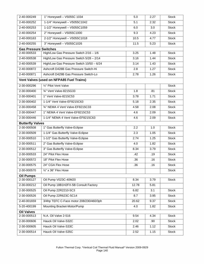
Fulton Thermal Corp. *Vertical Coil Thermal Fluid Manual* Version 2009-0929 Page 140
2-40-000249 1” Honeywell – V5055C 1034 5.0 2.27 Stock
2-40-000252 1-1/4” Honeywell – V5055C1042 5.1 2.32 Stock
2-40-000253 1-1/2” Honeywell – V5055C1059 6.0 3.0 Stock
2-40-000254 2” Honeywell – V5055C1000 9.3 4.23 Stock
2-40-000163 2-1/2” Honeywell – V5055C1018 10.5 4.77 Stock
2-40-000255 3” Honeywell – V5055C1026 11.5 5.23 Stock
Gas Pressure Switches 2-40-000533 High/Low Gas Pressure Switch 2/16 – 1/6 3.25 1.48 Stock
2-40-000538 High/Low Gas Pressure Switch 5/28 – 2/14 3.16 1.44 Stock
2-40-000539 High/Low Gas Pressure Switch 10/50 – 6/24 3.14 1.43 Stock
2-40-000872 Ashcroft D428B Gas Pressure Switch-Hi 2.8 1.27 Stock
2-40-000871 Ashcroft D429B Gas Pressure Switch-Lo 2.78 1.26 Stock
Vent Valves (used on NFPA85 Fuel Trains) 2-30-000296 ½” Pilot Vent Valve Stock
2-30-000400 ¾” Vent Valve-8215G33 1.8 .81 Stock
2-30-000401 1” Vent Valve-8215C53 3.78 1.71 Stock
2-30-000402 1-1/4” Vent Valve-EF8215C63 5.18 2.35 Stock
2-30-000458 ¾” NEMA 4 Vent Valve-EF8215C33 4.58 2.08 Stock
2-30-000447 1” NEMA 4 Vent Valve-EF8215C53 4.6 2.09 Stock
2-30-000446 1-1/4” NEMA 4 Vent Valve-EF8215C63 4.6 2.09 Stock
Butterfly Valves 2-30-000508 1” Gas Butterfly Valve-Eclipse 2.2 1.0 Stock
2-30-000509 1-1/4” Gas Butterfly Valve-Eclipse 2.3 1.05 Stock
2-30-000510 1-1/2” Gas Butterfly Valve-Eclipse 2.74 1.25 Stock
2-30-000511 2” Gas Butterfly Valve-Eclipse 4.0 1.82 Stock
2-30-000512 3” Gas Butterfly Valve-Eclipse 8.34 3.79 Stock
2-30-000533 24” Pilot Flex Hose .42 .19 Stock
2-30-000572 18” Pilot Flex Hose .36 .16 Stock
2-30-000575 24” CGA Flex Hose .36 .16 Stock
2-30-000570 ½” x 36” Flex Hose Stock
Oil Pumps 2-30-000127 Oil Pump V023C-40M20 8.34 3.79 Stock
2-30-000212 Oil Pump 18B1H2FX-5B Consult Factory 12.78 5.81 2-30-000525 Oil Pump 22R2210-5C3 6.82 3.1 Stock
2-30-000526 Oil Pump 22R623C-5C14 8.7 3.95 Stock
2-40-001659 3/4hp TEFC C-Face motor 208/230/460/3ph 20.62 9.37 Stock
5-20-400199 Mounting Bracket-Motor/Pump 4.0 1.82 Stock
Oil Valves 2-30-000513 N.A. Oil Valve 2-516 9.54 4.34 Stock
2-30-000606 Hauck Oil Valve-S32C 2.02 .90 Stock
2-30-000605 Hauck Oil Valve-S33C 2.46 1.12 Stock
2-30-000514 Hauck Oil Valve-S35C 2.52 1.15 Stock
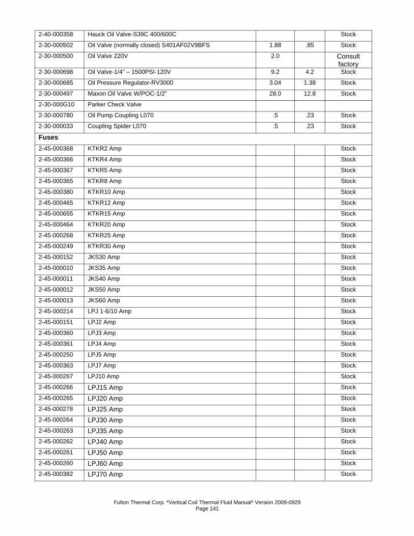
Fulton Thermal Corp. *Vertical Coil Thermal Fluid Manual* Version 2009-0929 Page 141
2-40-000358 Hauck Oil Valve-S39C 400/600C Stock
2-30-000502 Oil Valve (normally closed) S401AF02V9BFS 1.88 .85 Stock
2-30-000500 Oil Valve 220V 2.0 Consult factory
2-30-000698 Oil Valve-1/4” – 1500PSI-120V 9.2 4.2 Stock
2-30-000685 Oil Pressure Regulator-RV3000 3.04 1.38 Stock
2-30-000497 Maxon Oil Valve W/POC-1/2” 28.0 12.8 Stock
2-30-000G10 Parker Check Valve 2-30-000780 Oil Pump Coupling L070 .5 .23 Stock
2-30-000033 Coupling Spider L070 .5 .23 Stock
Fuses 2-45-000368 KTKR2 Amp Stock
2-45-000366 KTKR4 Amp Stock
2-45-000367 KTKR5 Amp Stock
2-45-000365 KTKR8 Amp Stock
2-45-000380 KTKR10 Amp Stock
2-45-000465 KTKR12 Amp Stock
2-45-000655 KTKR15 Amp Stock
2-45-000464 KTKR20 Amp Stock
2-45-000268 KTKR25 Amp Stock
2-45-000249 KTKR30 Amp Stock
2-45-000152 JKS30 Amp Stock
2-45-000010 JKS35 Amp Stock
2-45-000011 JKS40 Amp Stock
2-45-000012 JKS50 Amp Stock
2-45-000013 JKS60 Amp Stock
2-45-000214 LPJ 1-6/10 Amp Stock
2-45-000151 LPJ2 Amp Stock
2-45-000360 LPJ3 Amp Stock
2-45-000361 LPJ4 Amp Stock
2-45-000250 LPJ5 Amp Stock
2-45-000363 LPJ7 Amp Stock
2-45-000267 LPJ10 Amp Stock
2-45-000266 LPJ15 Amp Stock
2-45-000265 LPJ20 Amp Stock
2-45-000278 LPJ25 Amp Stock
2-45-000264 LPJ30 Amp Stock
2-45-000263 LPJ35 Amp Stock
2-45-000262 LPJ40 Amp Stock
2-45-000261 LPJ50 Amp Stock
2-45-000260 LPJ60 Amp Stock
2-45-000382 LPJ70 Amp Stock
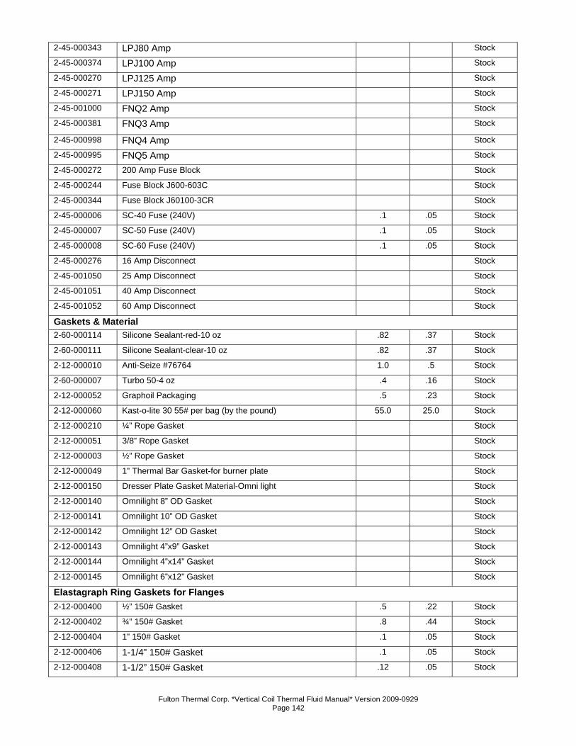
Fulton Thermal Corp. *Vertical Coil Thermal Fluid Manual* Version 2009-0929 Page 142
2-45-000343 LPJ80 Amp Stock
2-45-000374 LPJ100 Amp Stock
2-45-000270 LPJ125 Amp Stock
2-45-000271 LPJ150 Amp Stock
2-45-001000 FNQ2 Amp Stock
2-45-000381 FNQ3 Amp Stock
2-45-000998 FNQ4 Amp Stock
2-45-000995 FNQ5 Amp Stock
2-45-000272 200 Amp Fuse Block Stock
2-45-000244 Fuse Block J600-603C Stock
2-45-000344 Fuse Block J60100-3CR Stock
2-45-000006 SC-40 Fuse (240V) .1 .05 Stock
2-45-000007 SC-50 Fuse (240V) .1 .05 Stock
2-45-000008 SC-60 Fuse (240V) .1 .05 Stock
2-45-000276 16 Amp Disconnect Stock
2-45-001050 25 Amp Disconnect Stock
2-45-001051 40 Amp Disconnect Stock
2-45-001052 60 Amp Disconnect Stock
Gaskets & Material 2-60-000114 Silicone Sealant-red-10 oz .82 .37 Stock
2-60-000111 Silicone Sealant-clear-10 oz .82 .37 Stock
2-12-000010 Anti-Seize #76764 1.0 .5 Stock
2-60-000007 Turbo 50-4 oz .4 .16 Stock
2-12-000052 Graphoil Packaging .5 .23 Stock
2-12-000060 Kast-o-lite 30 55# per bag (by the pound) 55.0 25.0 Stock
2-12-000210 ¼” Rope Gasket Stock
2-12-000051 3/8” Rope Gasket Stock
2-12-000003 ½” Rope Gasket Stock
2-12-000049 1” Thermal Bar Gasket-for burner plate Stock
2-12-000150 Dresser Plate Gasket Material-Omni light Stock
2-12-000140 Omnilight 8” OD Gasket Stock
2-12-000141 Omnilight 10” OD Gasket Stock
2-12-000142 Omnilight 12” OD Gasket Stock
2-12-000143 Omnilight 4”x9” Gasket Stock
2-12-000144 Omnilight 4”x14” Gasket Stock
2-12-000145 Omnilight 6”x12” Gasket Stock
Elastagraph Ring Gaskets for Flanges 2-12-000400 ½” 150# Gasket .5 .22 Stock
2-12-000402 ¾” 150# Gasket .8 .44 Stock
2-12-000404 1” 150# Gasket .1 .05 Stock
2-12-000406 1-1/4” 150# Gasket .1 .05 Stock
2-12-000408 1-1/2” 150# Gasket .12 .05 Stock
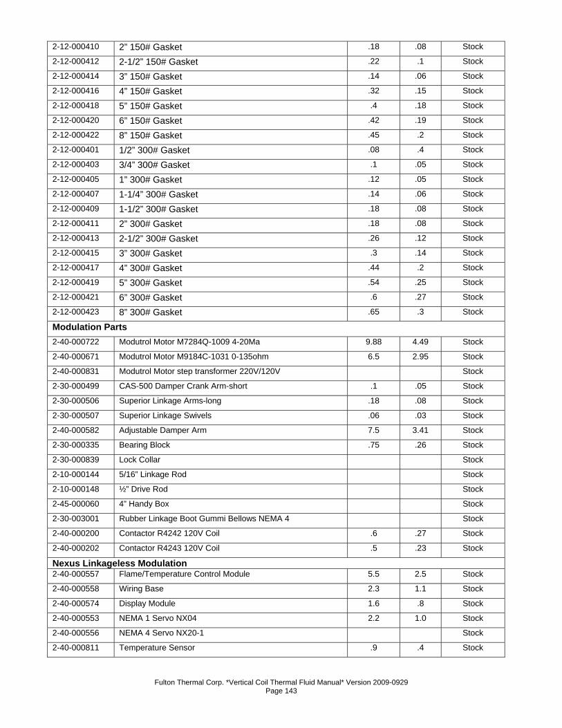
Fulton Thermal Corp. *Vertical Coil Thermal Fluid Manual* Version 2009-0929 Page 143
2-12-000410 2” 150# Gasket .18 .08 Stock
2-12-000412 2-1/2” 150# Gasket .22 .1 Stock
2-12-000414 3” 150# Gasket .14 .06 Stock
2-12-000416 4” 150# Gasket .32 .15 Stock
2-12-000418 5” 150# Gasket .4 .18 Stock
2-12-000420 6” 150# Gasket .42 .19 Stock
2-12-000422 8” 150# Gasket .45 .2 Stock
2-12-000401 1/2” 300# Gasket .08 .4 Stock
2-12-000403 3/4” 300# Gasket .1 .05 Stock
2-12-000405 1” 300# Gasket .12 .05 Stock
2-12-000407 1-1/4” 300# Gasket .14 .06 Stock
2-12-000409 1-1/2” 300# Gasket .18 .08 Stock
2-12-000411 2” 300# Gasket .18 .08 Stock
2-12-000413 2-1/2” 300# Gasket .26 .12 Stock
2-12-000415 3” 300# Gasket .3 .14 Stock
2-12-000417 4” 300# Gasket .44 .2 Stock
2-12-000419 5” 300# Gasket .54 .25 Stock
2-12-000421 6” 300# Gasket .6 .27 Stock
2-12-000423 8” 300# Gasket .65 .3 Stock
Modulation Parts 2-40-000722 Modutrol Motor M7284Q-1009 4-20Ma 9.88 4.49 Stock
2-40-000671 Modutrol Motor M9184C-1031 0-135ohm 6.5 2.95 Stock
2-40-000831 Modutrol Motor step transformer 220V/120V Stock
2-30-000499 CAS-500 Damper Crank Arm-short .1 .05 Stock
2-30-000506 Superior Linkage Arms-long .18 .08 Stock
2-30-000507 Superior Linkage Swivels .06 .03 Stock
2-40-000582 Adjustable Damper Arm 7.5 3.41 Stock
2-30-000335 Bearing Block .75 .26 Stock
2-30-000839 Lock Collar Stock
2-10-000144 5/16” Linkage Rod Stock
2-10-000148 ½” Drive Rod Stock
2-45-000060 4” Handy Box Stock
2-30-003001 Rubber Linkage Boot Gummi Bellows NEMA 4 Stock
2-40-000200 Contactor R4242 120V Coil .6 .27 Stock
2-40-000202 Contactor R4243 120V Coil .5 .23 Stock
Nexus Linkageless Modulation 2-40-000557 Flame/Temperature Control Module 5.5 2.5 Stock
2-40-000558 Wiring Base 2.3 1.1 Stock
2-40-000574 Display Module 1.6 .8 Stock
2-40-000553 NEMA 1 Servo NX04 2.2 1.0 Stock
2-40-000556 NEMA 4 Servo NX20-1 Stock
2-40-000811 Temperature Sensor .9 .4 Stock
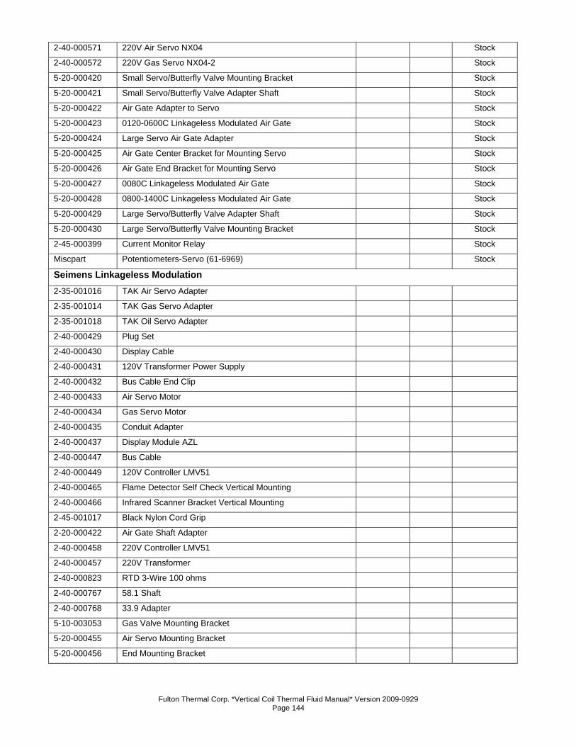
Fulton Thermal Corp. *Vertical Coil Thermal Fluid Manual* Version 2009-0929 Page 144
2-40-000571 220V Air Servo NX04 Stock
2-40-000572 220V Gas Servo NX04-2 Stock
5-20-000420 Small Servo/Butterfly Valve Mounting Bracket Stock
5-20-000421 Small Servo/Butterfly Valve Adapter Shaft Stock
5-20-000422 Air Gate Adapter to Servo Stock
5-20-000423 0120-0600C Linkageless Modulated Air Gate Stock
5-20-000424 Large Servo Air Gate Adapter Stock
5-20-000425 Air Gate Center Bracket for Mounting Servo Stock
5-20-000426 Air Gate End Bracket for Mounting Servo Stock
5-20-000427 0080C Linkageless Modulated Air Gate Stock
5-20-000428 0800-1400C Linkageless Modulated Air Gate Stock
5-20-000429 Large Servo/Butterfly Valve Adapter Shaft Stock
5-20-000430 Large Servo/Butterfly Valve Mounting Bracket Stock
2-45-000399 Current Monitor Relay Stock
Miscpart Potentiometers-Servo (61-6969) Stock
Seimens Linkageless Modulation 2-35-001016 TAK Air Servo Adapter 2-35-001014 TAK Gas Servo Adapter 2-35-001018 TAK Oil Servo Adapter 2-40-000429 Plug Set 2-40-000430 Display Cable 2-40-000431 120V Transformer Power Supply 2-40-000432 Bus Cable End Clip 2-40-000433 Air Servo Motor 2-40-000434 Gas Servo Motor 2-40-000435 Conduit Adapter 2-40-000437 Display Module AZL 2-40-000447 Bus Cable 2-40-000449 120V Controller LMV51 2-40-000465 Flame Detector Self Check Vertical Mounting 2-40-000466 Infrared Scanner Bracket Vertical Mounting 2-45-001017 Black Nylon Cord Grip 2-20-000422 Air Gate Shaft Adapter 2-40-000458 220V Controller LMV51 2-40-000457 220V Transformer 2-40-000823 RTD 3-Wire 100 ohms 2-40-000767 58.1 Shaft 2-40-000768 33.9 Adapter 5-10-003053 Gas Valve Mounting Bracket 5-20-000455 Air Servo Mounting Bracket 5-20-000456 End Mounting Bracket
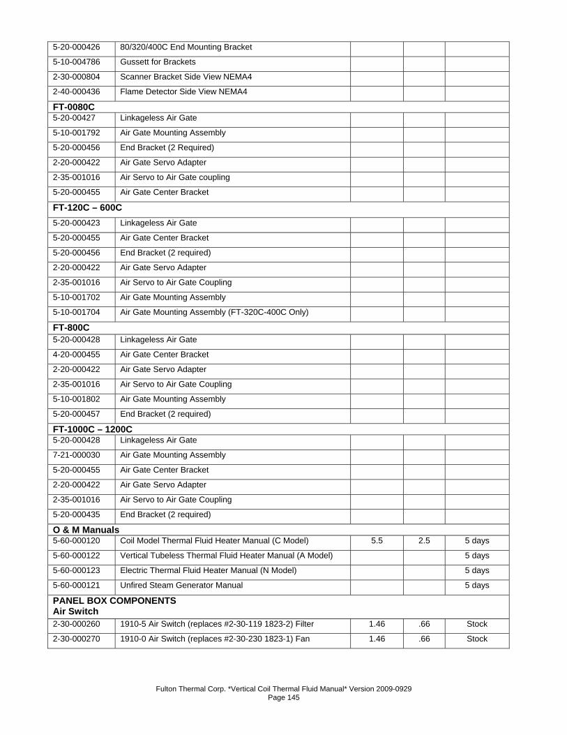
Fulton Thermal Corp. *Vertical Coil Thermal Fluid Manual* Version 2009-0929 Page 145
5-20-000426 80/320/400C End Mounting Bracket 5-10-004786 Gussett for Brackets 2-30-000804 Scanner Bracket Side View NEMA4 2-40-000436 Flame Detector Side View NEMA4 FT-0080C 5-20-00427 Linkageless Air Gate 5-10-001792 Air Gate Mounting Assembly 5-20-000456 End Bracket (2 Required) 2-20-000422 Air Gate Servo Adapter 2-35-001016 Air Servo to Air Gate coupling 5-20-000455 Air Gate Center Bracket FT-120C – 600C 5-20-000423 Linkageless Air Gate 5-20-000455 Air Gate Center Bracket 5-20-000456 End Bracket (2 required) 2-20-000422 Air Gate Servo Adapter 2-35-001016 Air Servo to Air Gate Coupling 5-10-001702 Air Gate Mounting Assembly 5-10-001704 Air Gate Mounting Assembly (FT-320C-400C Only) FT-800C 5-20-000428 Linkageless Air Gate 4-20-000455 Air Gate Center Bracket 2-20-000422 Air Gate Servo Adapter 2-35-001016 Air Servo to Air Gate Coupling 5-10-001802 Air Gate Mounting Assembly 5-20-000457 End Bracket (2 required) FT-1000C – 1200C 5-20-000428 Linkageless Air Gate 7-21-000030 Air Gate Mounting Assembly 5-20-000455 Air Gate Center Bracket 2-20-000422 Air Gate Servo Adapter 2-35-001016 Air Servo to Air Gate Coupling 5-20-000435 End Bracket (2 required) O & M Manuals 5-60-000120 Coil Model Thermal Fluid Heater Manual (C Model) 5.5 2.5 5 days
5-60-000122 Vertical Tubeless Thermal Fluid Heater Manual (A Model) 5 days
5-60-000123 Electric Thermal Fluid Heater Manual (N Model) 5 days
5-60-000121 Unfired Steam Generator Manual 5 days
PANEL BOX COMPONENTS Air Switch 2-30-000260 1910-5 Air Switch (replaces #2-30-119 1823-2) Filter 1.46 .66 Stock
2-30-000270 1910-0 Air Switch (replaces #2-30-230 1823-1) Fan 1.46 .66 Stock
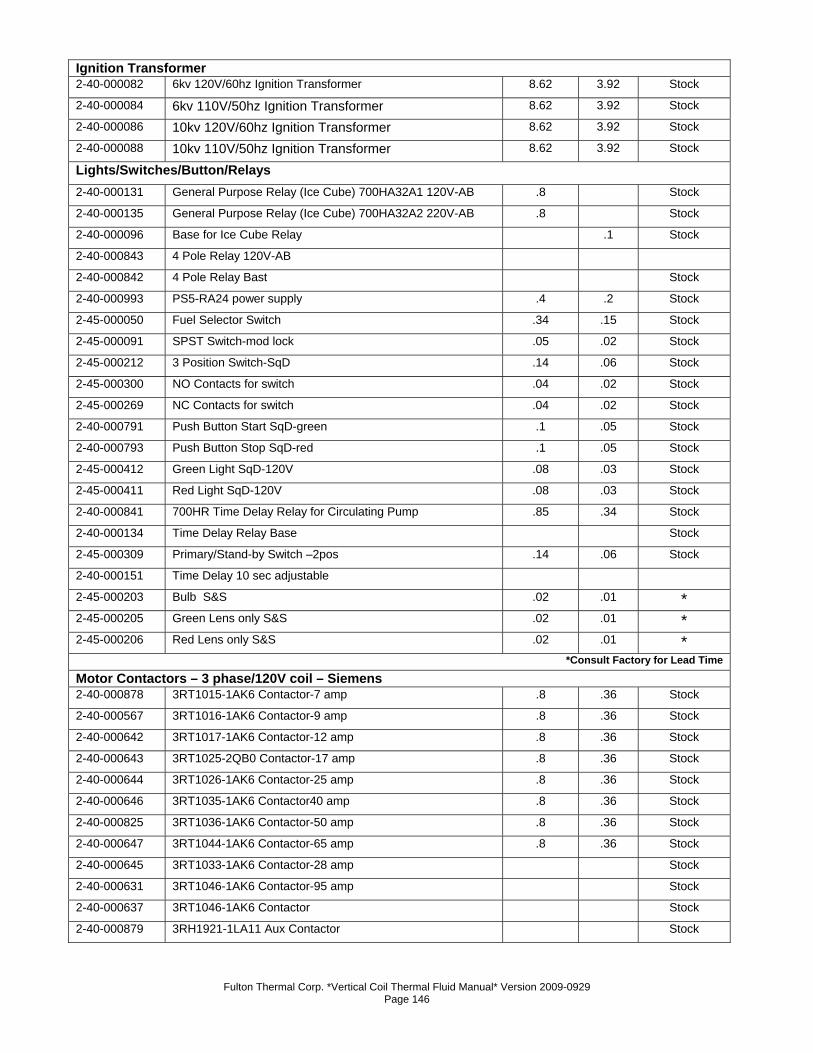
Fulton Thermal Corp. *Vertical Coil Thermal Fluid Manual* Version 2009-0929 Page 146
Ignition Transformer 2-40-000082 6kv 120V/60hz Ignition Transformer 8.62 3.92 Stock
2-40-000084 6kv 110V/50hz Ignition Transformer 8.62 3.92 Stock
2-40-000086 10kv 120V/60hz Ignition Transformer 8.62 3.92 Stock
2-40-000088 10kv 110V/50hz Ignition Transformer 8.62 3.92 Stock
Lights/Switches/Button/Relays 2-40-000131 General Purpose Relay (Ice Cube) 700HA32A1 120V-AB .8 Stock
2-40-000135 General Purpose Relay (Ice Cube) 700HA32A2 220V-AB .8 Stock
2-40-000096 Base for Ice Cube Relay .1 Stock
2-40-000843 4 Pole Relay 120V-AB
2-40-000842 4 Pole Relay Bast Stock
2-40-000993 PS5-RA24 power supply .4 .2 Stock
2-45-000050 Fuel Selector Switch .34 .15 Stock
2-45-000091 SPST Switch-mod lock .05 .02 Stock
2-45-000212 3 Position Switch-SqD .14 .06 Stock
2-45-000300 NO Contacts for switch .04 .02 Stock
2-45-000269 NC Contacts for switch .04 .02 Stock
2-40-000791 Push Button Start SqD-green .1 .05 Stock
2-40-000793 Push Button Stop SqD-red .1 .05 Stock
2-45-000412 Green Light SqD-120V .08 .03 Stock
2-45-000411 Red Light SqD-120V .08 .03 Stock
2-40-000841 700HR Time Delay Relay for Circulating Pump .85 .34 Stock
2-40-000134 Time Delay Relay Base Stock
2-45-000309 Primary/Stand-by Switch –2pos .14 .06 Stock
2-40-000151 Time Delay 10 sec adjustable 2-45-000203 Bulb S&S .02 .01 * 2-45-000205 Green Lens only S&S .02 .01 * 2-45-000206 Red Lens only S&S .02 .01 *
*Consult Factory for Lead Time
Motor Contactors – 3 phase/120V coil – Siemens 2-40-000878 3RT1015-1AK6 Contactor-7 amp .8 .36 Stock
2-40-000567 3RT1016-1AK6 Contactor-9 amp .8 .36 Stock
2-40-000642 3RT1017-1AK6 Contactor-12 amp .8 .36 Stock
2-40-000643 3RT1025-2QB0 Contactor-17 amp .8 .36 Stock
2-40-000644 3RT1026-1AK6 Contactor-25 amp .8 .36 Stock
2-40-000646 3RT1035-1AK6 Contactor40 amp .8 .36 Stock
2-40-000825 3RT1036-1AK6 Contactor-50 amp .8 .36 Stock
2-40-000647 3RT1044-1AK6 Contactor-65 amp .8 .36 Stock
2-40-000645 3RT1033-1AK6 Contactor-28 amp Stock
2-40-000631 3RT1046-1AK6 Contactor-95 amp Stock
2-40-000637 3RT1046-1AK6 Contactor Stock
2-40-000879 3RH1921-1LA11 Aux Contactor Stock
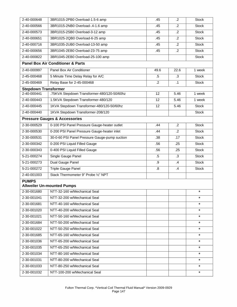
Fulton Thermal Corp. *Vertical Coil Thermal Fluid Manual* Version 2009-0929 Page 147
2-40-000648 3BR1015-2PB0 Overload-1.5-6 amp .45 .2 Stock
2-40-000566 3BR1015-2NB0 Overload-.4-1.6 amp .45 .2 Stock
2-40-000573 3BR1015-2SB0 Overload-3-12 amp .45 .2 Stock
2-40-000651 3BR1025-2QB0 Overload-6-25 amp .45 .2 Stock
2-40-000716 3BR1035-2UB0 Overload-13-50 amp .45 .2 Stock
2-40-000656 3BR1045-2EB0 Overload-23-75 amp .45 .2 Stock
2-40-000822 3BR1045-2EB0 Overload-25-100 amp Stock
Panel Box Air Conditioner & Parts 2-40-000997 Panel Box Air Conditioner 49.6 22.6 1 week
2-45-000468 5 Minute Time Delay Relay for A/C .5 .3 Stock
2-45-000469 Relay Base for 2-45-000468 .2 .1 Stock
Stepdown Transformer 2-40-000441 .75KVA Stepdown Transformer-480/120-50/60hz 12 5.46 1 week
2-40-000443 1.5KVA Stepdown Transformer-480/120 12 5.46 1 week
2-40-000445 1KVA Stepdown Transformer-480/120-50/60hz 12 5.46 Stock
2-40-000440 1KVA Stepdown Transformer-208/120 Stock
Pressure Gauges & Accessories 2-30-000529 0-100 PSI Panel Pressure Gauge-heater outlet .44 .2 Stock
2-30-000530 0-200 PSI Panel Pressure Gauge-heater inlet .44 .2 Stock
2-30-000531 30-0-60 PSI Panel Pressure Gauge-pump suction .38 .17 Stock
2-30-000342 0-200 PSI Liquid Filled Gauge .56 .25 Stock
2-30-000343 0-400 PSI Liquid Filled Gauge .56 .25 Stock
5-21-000274 Single Gauge Panel .5 .3 Stock
5-21-000273 Dual Gauge Panel .9 .4 Stock
5-21-000272 Triple Gauge Panel .8 .4 Stock
2-40-001003 Stack Thermometer 9” Probe ½” NPT PUMPS Allweiler Un-mounted Pumps 2-30-001680 NTT-32-160 w/Mechanical Seal * 2-30-001041 NTT-32-200 w/Mechanical Seal * 2-30-001681 NTT-40-160 w/Mechanical Seal * 2-30-001020 NTT-40-200 w/Mechanical Seal * 2-30-001021 NTT-50-160 w/Mechanical Seal * 2-30-001684 NTT-50-200 w/Mechanical Seal * 2-30-001022 NTT-50-250 w/Mechanical Seal * 2-30-001685 NTT-65-160 w/Mechanical Seal * 2-30-001036 NTT-65-200 w/Mechanical Seal * 2-30-001035 NTT-65-250 w/Mechanical Seal * 2-30-001034 NTT-80-160 w/Mechanical Seal * 2-30-001031 NTT-80-200 w/Mechanical Seal * 2-30-001033 NTT-80-250 w/Mechanical Seal * 2-30-001032 NTT-100-200 w/Mechanical Seal *
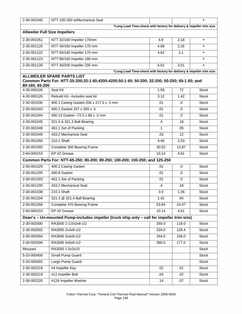
Fulton Thermal Corp. *Vertical Coil Thermal Fluid Manual* Version 2009-0929 Page 148
2-30-001040 NTT-100-250 w/Mechanical Seal * *Long Lead Time-check with factory for delivery & impeller trim size
Allweiler Full Size Impellers
2-30-001051 NTT 32/160 Impeller 170mm 4.8 2.18 * 2-30-001120 NTT 40/160 Impeller 170 mm 4.98 2.26 * 2-30-001122 NTT 65/160 Impeller 170 mm 4.62 2.1 * 2-30-001123 NTT 80/160 Impeller 180 mm * 2-30-001126 NTT 40/200 Impeller 205 mm 6.62 3.01 *
*Long Lead Time-check with factory for delivery & impeller trim sizeALLWEILER SPARE PARTS LIST Common Parts For: NTT-25-200;32-1 60;4200;4250;50-1 60; 50-200; 32-200; 50-250; 65-1 60; and 80-160, 65-200 4-30-000106 Seal Kit 1.58 .72 Stock
4-30-000126 Rebuild Kit –Includes seal kit 3.12 1.42 Stock
2-30-001030 400.1 Casing Gasket-206 x 217.5 x .5 mm .01 .0 Stock
2-30-001043 400.2 Gasket 257 x 269 x .5 .01 .0 Stock
2-30-001044 400.13 Gasket –72.5 x 88 x .5 mm .01 .0 Stock
2-30-001045 321.4 & 321.3 Ball Bearing .4 .18 Stock
2-30-001048 461.1 Set of Packing .1 .05 Stock
2-30-001049 433.2 Mechanical Seal .26 .12 Stock
2-30-001050 210.1 Shaft 4.46 2.03 Stock
2-30-001055 Complete 360 Bearing Frame 30.52 13.87 Stock
2-60-000153 EP #2 Grease 10.14 4.61 Stock
Common Parts For: NTT-65-250; 80-200; 80-250; 100-200; 100-250; and 125-250 2-30-001029 400.2 Casing Gasket .01 .0 Stock
2-30-001205 400.8 Gasket .01 .0 Stock
2-30-001203 461.1 Set of Packing .01 .0 Stock
2-30-001200 433.2 Mechanical Seal .4 .18 Stock
2-30-001038 210.1 Shaft 3.0 1.36 Stock
2-30-001204 321.3 @ 321.4 Ball Bearing 1.42 .65 Stock
2-30-001058 Complete 470 Bearing Frame 53.84 24.47 Stock
2-60-000153 EP #2 Grease 10.14 4.61 Stock
Dean’s – Un-mounted Pump-includes impeller (truck ship only – call for impeller trim size) 2-30-002000 RA3000 1-1/2x3x8-1/2 260.0 118.0 Stock
2-30-002002 RA3000 2x3x8-1/2 316.0 126.4 Stock
2-30-002004 RA3000 3x4x8-1/2 344.0 156.0 Stock
2-30-002006 RA3000 4x6x8-1/2 390.0 177.0 Stock
Miscpart RA3000 1.5x3x10 Stock
5-20-000400 Small Pump Guard Stock
5-20-000402 Large Pump Guard Stock
2-30-002218 #4 Impeller Key .02 .01 Stock
2-30-002219 #12 Impeller Bolt .04 .02 Stock
2-30-002220 #12A Impeller Washer .14 .07 Stock
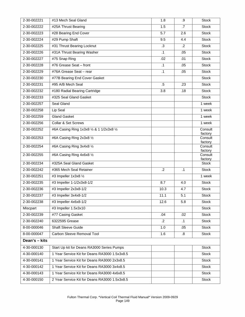
Fulton Thermal Corp. *Vertical Coil Thermal Fluid Manual* Version 2009-0929 Page 149
2-30-002221 #13 Mech Seal Gland 1.8 .9 Stock
2-30-002222 #25A Thrust Bearing 1.5 .7 Stock
2-30-002223 #28 Bearing End Cover 5.7 2.6 Stock
2-30-002224 #29 Pump Shaft 9.5 4.4 Stock
2-30-002225 #31 Thrust Bearing Locknut .3 .2 Stock
2-30-002226 #31A Thrust Bearing Washer .1 .05 Stock
2-30-002227 #75 Snap Ring .02 .01 Stock
2-30-002228 #76 Grease Seat – front .1 .05 Stock
2-30-002229 #76A Grease Seat – rear .1 .05 Stock
2-30-002230 #77B Bearing End Cover Gasket Stock
2-30-002231 #95 A/B Mech Seal .5 .23 Stock
2-30-002232 #180 Radial Bearing Cartridge 3.8 .18 Stock
2-30-002233 #325 Seal Gland Gasket Stock
2-30-002257 Seal Gland 1 week
2-30-002258 Lip Seal 1 week
2-30-002259 Gland Gasket 1 week
2-30-002256 Collar & Set Screws 1 week
2-30-002252 #6A Casing Ring 1x3x8 ½ & 1 1/2x3x8 ½ Consult factory
2-30-002253 #6A Casing Ring 2x3x8 ½ Consult factory
2-30-002254 #6A Casing Ring 3x4x8 ½ Consult factory
2-30-002255 #6A Casing Ring 4x6x8 ½ Consult factory
2-30-002234 #325A Seal Gland Gasket Stock
2-30-002242 #365 Mech Seal Retainer .2 .1 Stock
2-30-002251 #3 Impeller 1x3x8 ½ 1 week
2-30-002235 #3 Impeller 1-1/2x3x8-1/2 8.7 4.0 Stock
2-30-002236 #3 Impeller 2x3x8-1/2 10.3 4.7 Stock
2-30-002237 #3 Impeller 3x4x8-1/2 11.1 5.1 Stock
2-30-002238 #3 Impeller 4x6x8-1/2 12.6 5.8 Stock
Miscpart #3 Impeller 1.5x3x10 Stock
2-30-002239 #77 Casing Gasket .04 .02 Stock
2-30-002240 6322595 Grease .2 .1 Stock
8-00-000046 Shaft Sleeve Guide 1.0 .05 Stock
8-00-000047 Carbon Sleeve Removal Tool 1.6 .8 Stock
Dean’s – kits 4-30-000130 Start Up kit for Deans RA3000 Series Pumps Stock 4-30-000140 1 Year Service Kit for Deans RA3000 1.5x3x8.5 Stock 4-30-000141 1 Year Service Kit for Deans RA3000 2x3x8.5 Stock 4-30-000142 1 Year Service Kit for Deans RA3000 3x4x8.5 Stock 4-30-000143 1 Year Service Kit for Deans RA3000 4x6x8.5 Stock 4-30-000150 2 Year Service Kit for Deans RA3000 1.5x3x8.5 Stock
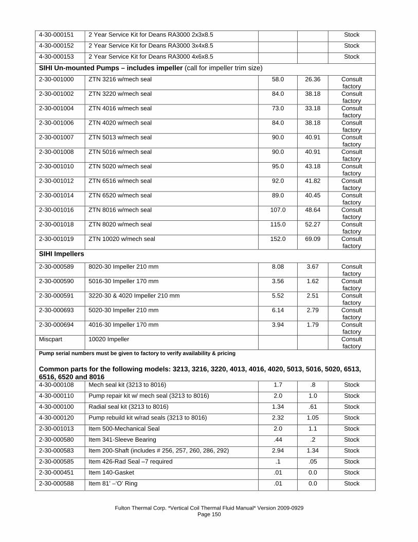
Fulton Thermal Corp. *Vertical Coil Thermal Fluid Manual* Version 2009-0929 Page 150
4-30-000151 2 Year Service Kit for Deans RA3000 2x3x8.5 Stock 4-30-000152 2 Year Service Kit for Deans RA3000 3x4x8.5 Stock 4-30-000153 2 Year Service Kit for Deans RA3000 4x6x8.5 Stock SIHI Un-mounted Pumps – includes impeller (call for impeller trim size) 2-30-001000 ZTN 3216 w/mech seal 58.0 26.36 Consult
factory 2-30-001002 ZTN 3220 w/mech seal 84.0 38.18 Consult
factory 2-30-001004 ZTN 4016 w/mech seal 73.0 33.18 Consult
factory 2-30-001006 ZTN 4020 w/mech seal 84.0 38.18 Consult
factory 2-30-001007 ZTN 5013 w/mech seal 90.0 40.91 Consult
factory 2-30-001008 ZTN 5016 w/mech seal 90.0 40.91 Consult
factory 2-30-001010 ZTN 5020 w/mech seal 95.0 43.18 Consult
factory 2-30-001012 ZTN 6516 w/mech seal 92.0 41.82 Consult
factory 2-30-001014 ZTN 6520 w/mech seal 89.0 40.45 Consult
factory 2-30-001016 ZTN 8016 w/mech seal 107.0 48.64 Consult
factory 2-30-001018 ZTN 8020 w/mech seal 115.0 52.27 Consult
factory 2-30-001019 ZTN 10020 w/mech seal 152.0 69.09 Consult
factory SIHI Impellers
2-30-000589 8020-30 Impeller 210 mm 8.08 3.67 Consult factory
2-30-000590 5016-30 Impeller 170 mm 3.56 1.62 Consult factory
2-30-000591 3220-30 & 4020 Impeller 210 mm 5.52 2.51 Consult factory
2-30-000693 5020-30 Impeller 210 mm 6.14 2.79 Consult factory
2-30-000694 4016-30 Impeller 170 mm 3.94 1.79 Consult factory
Miscpart 10020 Impeller Consult factory
Pump serial numbers must be given to factory to verify availability & pricing Common parts for the following models: 3213, 3216, 3220, 4013, 4016, 4020, 5013, 5016, 5020, 6513, 6516, 6520 and 8016 4-30-000108 Mech seal kit (3213 to 8016) 1.7 .8 Stock
4-30-000110 Pump repair kit w/ mech seal (3213 to 8016) 2.0 1.0 Stock
4-30-000100 Radial seal kit (3213 to 8016) 1.34 .61 Stock
4-30-000120 Pump rebuild kit w/rad seals (3213 to 8016) 2.32 1.05 Stock
2-30-001013 Item 500-Mechanical Seal 2.0 1.1 Stock
2-30-000580 Item 341-Sleeve Bearing .44 .2 Stock
2-30-000583 Item 200-Shaft (includes # 256, 257, 260, 286, 292) 2.94 1.34 Stock
2-30-000585 Item 426-Rad Seal –7 required .1 .05 Stock
2-30-000451 Item 140-Gasket .01 0.0 Stock
2-30-000588 Item 81’ –‘O’ Ring .01 0.0 Stock
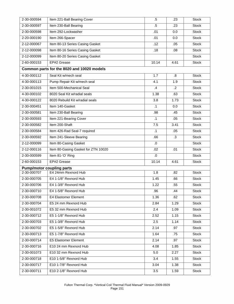
Fulton Thermal Corp. *Vertical Coil Thermal Fluid Manual* Version 2009-0929 Page 151
2-30-000594 Item 221-Ball Bearing Cover .5 .23 Stock
2-30-000597 Item 230-Ball Bearing .5 .23 Stock
2-30-000598 Item 292-Lockwasher .01 0.0 Stock
2-20-000190 Item 266-Spacer .01 0.0 Stock
2-12-000067 Item 80-13 Series Casing Gasket .12 .05 Stock
2-12-000098 Item 80-16 Series Casing Gasket .18 .08 Stock
2-12-000099 Item 80-20 Series Casing Gasket Stock
2-60-000153 EP#2 Grease 10.14 4.61 Stock
Common parts for the 8020 and 10020 models 4-30-000112 Seal Kit w/mech seal 1.7 .8 Stock
4-30-000113 Pump Repair Kit w/mech seal 4.1 1.9 Stock
2-30-001015 Item 500-Mechanical Seal .4 .2 Stock
4-30-000102 8020 Seal Kit w/radial seals 1.38 .63 Stock
4-30-000122 8020 Rebuild Kit w/radial seals 3.8 1.73 Stock
2-30-000451 Item 140-Gasket .1 0.0 Stock
2-30-000581 Item 230-Ball Bearing .98 .45 Stock
2-30-000593 Item 221-Bearing Cover .1 .05 Stock
2-30-000582 Item 200-Shaft 7.5 3.41 Stock
2-30-000584 Item 426-Rad Seal-7 required .1 .05 Stock
2-30-000592 Item 241-Sleeve Bearing .66 .3 Stock
2-12-000099 Item 80-Casing Gasket .0 Stock
2-12-000116 Item 80-Gasing Gasket for ZTN 10020 .02 .01 Stock
2-30-000599 Item 81-‘O’ Ring .0 Stock
2-60-000153 EP#2 Grease 10.14 4.61 Stock
Pump/motor coupling parts 2-30-000707 E4 24mm Rexnord Hub 1.8 .82 Stock
2-30-000705 E4 1-1/8” Rexnord Hub 1.45 .66 Stock
2-30-000706 E4 1-3/8” Rexnord Hub 1.22 .55 Stock
2-30-000710 E4 1-5/8” Rexnord Hub .96 .44 Stock
2-30-000708 E4 Elastomer Element 1.36 .62 Stock
2-30-000704 E5 24 mm Rexnord Hub 2.84 1.29 Stock
2-30-001072 E5 32 mm Rexnord Hub 2.4 1.09 Stock
2-30-000712 E5 1-1/8” Rexnord Hub 2.52 1.15 Stock
2-30-000703 E5 1-3/8” Rexnord Hub 2.5 1.14 Stock
2-30-000702 E5 1-5/8” Rexnord Hub 2.14 .97 Stock
2-30-000713 E5 1-7/8” Rexnord Hub 1.64 .75 Stock
2-30-000714 E5 Elastomer Element 2.14 .97 Stock
2-30-000716 E10 24 mm Rexnord Hub 4.08 1.85 Stock
2-30-001073 E10 32 mm Rexnord Hub 5.0 2.27 Stock
2-30-000718 E10 1-5/8” Rexnord Hub 3.4 1.55 Stock
2-30-000717 E10 1-7/8” Rexnord Hub 3.04 1.38 Stock
2-30-000711 E10 2-1/8” Rexnord Hub 3.5 1.59 Stock
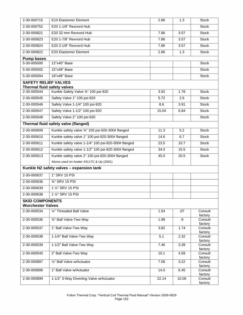
Fulton Thermal Corp. *Vertical Coil Thermal Fluid Manual* Version 2009-0929 Page 152
2-30-000715 E10 Elastomer Element 2.86 1.3 Stock
2-30-000752 E20 1-1/8” Rexnord Hub Stock
2-30-000821 E20 32 mm Rexnord Hub 7.86 3.57 Stock
2-30-000823 E20 1-7/8” Rexnord Hub 7.86 3.57 Stock
2-30-000824 E20 2-1/8” Rexnord Hub 7.86 3.57 Stock
2-30-000822 E20 Elastomer Element 2.86 1.3 Stock
Pump bases 5-30-005000 12”x40” Base Stock
5-30-005002 15”x48” Base Stock
5-30-005004 18”x48” Base Stock
SAFETY RELIEF VALVES Thermal fluid safety valves 2-30-000544 Kunkle Safety Valve ¾” 100 psi-920 3.92 1.78 Stock
2-30-000545 Safety Valve 1” 100 psi-920 5.72 2.6 Stock
2-30-000546 Safety Valve 1-1/4” 100 psi-920 8.6 3.91 Stock
2-30-000547 Safety Valve 1-1/2” 100 psi-920 15.04 6.84 Stock
2-30-000548 Safety Valve 2” 100 psi-920 Stock
Thermal fluid safety valve (flanged) 2-30-000609 Kunkle safety valve ¾” 100 psi-920-300# flanged 11.3 5.2 Stock
2-30-000610 Kunkle safety valve 1” 100 psi-920-300# flanged 14.6 6.7 Stock
2-30-000611 Kunkle safety valve 1-1/4” 100 psi-920-300# flanged 23.5 10.7 Stock
2-30-000612 Kunkle safety valve 1-1/2” 100 psi-920-300# flanged 34.0 15.5 Stock
2-30-000613 Kunkle safety valve 2” 100 psi-920-300# flanged Above used on heater #3117C & Up (2001)
45.0 20.5 Stock
Kunkle N2 safety valves – expansion tank 2-30-000637 1” SRV 15 PSI 2-30-000636 ¾” SRV 15 PSI 2-30-000639 1 ½” SRV 15 PSI 2-30-000638 1 ¼” SRV 15 PSI SKID COMPONENTS Worchester Valves 2-30-000534 ¼” Threaded Ball Valve 1.54 .07 Consult
factory 2-30-000536 ¾” Ball Valve-Two Way 1.98 .9 Consult
factory 2-30-000537 1” Ball Valve-Two Way 3.82 1.74 Consult
factory 2-30-000538 1-1/4” Ball Valve-Two Way 5.1 2.32 Consult
factory 2-30-000539 1-1/2” Ball Valve-Two Way 7.46 3.39 Consult
factory 2-30-000540 2” Ball Valve-Two Way 10.1 4.59 Consult
factory 2-30-000897 ½” Ball Valve w/Actuator 7.08 3.22 Consult
factory 2-30-000896 1” Ball Valve w/Actuator 14.0 6.45 Consult
factory 2-30-000899 1-1/2” 3-Way Diverting Valve w/Actuator 22.14 10.06 Consult
factory

Fulton Thermal Corp. *Vertical Coil Thermal Fluid Manual* Version 2009-0929 Page 153
2-30-000898 2” 3-Way Diverting Valve w/Actuator 25.84 11.75 Consult factory
2-30-001300 1-1/4” Valve Repair Kit .16 .07 Consult factory
2-30-001301 1-12” Valve Repair Kit .2 .09 Consult factory
2-30-001303 1039 Actuator Repair Kit .18 .08 Consult factory
2-30-001304 2039 Actuator Repair Kit .1 .08 Consult factory
2-30-001305 Series 1039 Actuator (1” and smaller) .06 .05 Consult factory
2-30-001313 1-1/4” S Ring .02 .03 Consult factory
2-30-001314 1-1/2” S Ring .02 .01 Consult factory
2-30-001315 2” S Ring .01 Consult factory
Dezurik Valves 2-30-000885 1.5” Dezurik Valve w/EI-O-Matic Actuator and Positioner Consult
factory 2-30-000820 2” Dezurik Valve w/EI-O-Matic Actuator and Positioner Consult
factory 2-30-000886 3” Dezurik Valve w/EI-O-Matic Actuator and Positioner Consult
factory 2-30-000882 3” Dezurik Valve Repair Kit Consult
factory 2-30-000880 2” Dezurik Valve Repair Kit Consult
factory 2-30-000883 1.5” Dezurik Valve Repair Kit .2 .1 Consult
factory 2-30-001261 ES10 Actuator Rebuild Kit .2 .1 Consult
factory 2-30-001260 ES20 Actuator Rebuild Kit .16 .07 Consult
factory 2-30-001276 1” Valve Actuator ES10-6 Consult
factory SteamPac Components 2-40-000420 Fulton Pump Relay –120V .5 .23 Stock
2-40-000422 Base for Fulton Pump Relay (8 pin) .25 .11 Stock
2-40-000403 IDIDO Relay 2.0 .91 Stock
2-40-000202 Motor Starter R4243 – 30 Amp .52 .24 Stock
2-40-000421 120V Water Level Relay Stock
2-40-000423 Base for 120V Water Level Relay (11 pin) Stock
2-40-000229 Pressuretrol L404A1396 2.0 .91 Stock
2-12-000004 Handhole Gasket .04 .02 Stock
2-12-000007 5/8”x9-1/4” Gauge Glass .2 .09 Stock
2-12-000019 5/8” Rubber Gasket .004 0.0 Stock
2-12-000020 5/8” Brass Gasket .002 0.0 Stock
2-30-000149 ½” Water Gauge Valve w/ ball checks 1.5 .68 Stock
2-30-000047 ½” Tri-cock .42 .19 Stock
2-20-000017 Low Water Cutoff Probe-17-1/8” – cut to any length .5 .23 Stock
2-20-000010 Low Water Probe .5 .23 Stock
2-20-000012 High Water Probe .5 .23 Stock
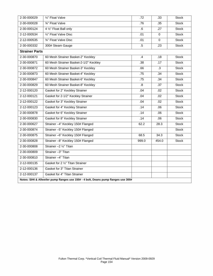
Fulton Thermal Corp. *Vertical Coil Thermal Fluid Manual* Version 2009-0929 Page 154
2-30-000029 ½” Float Valve .72 .33 Stock
2-30-000028 ¾” Float Valve .76 .35 Stock
2-30-000124 4 ½” Float Ball only .6 .27 Stock
2-12-000534 ½” Float Valve Disc .01 0 Stock
2-12-000535 ¾” Float Valve Disc .01 0 Stock
2-30-000332 300# Steam Gauge .5 .23 Stock
Strainer Parts 2-30-000870 60 Mesh Strainer Basket-2” Keckley .4 .18 Stock
2-30-000871 60 Mesh Strainer Basket-2-1/2” Keckley .38 .17 Stock
2-30-000872 60 Mesh Strainer Basket-3” Keckley .66 .3 Stock
2-30-000873 60 Mesh Strainer Basket-4” Keckley .75 .34 Stock
2-30-000847 60 Mesh Strainer Basket-6” Keckley .75 .34 Stock
2-30-000829 60 Mesh Strainer Basket-8” Keckley .8 .37 Stock
2-12-000120 Gasket for 2” Keckley Strainer .04 .02 Stock
2-12-000121 Gasket for 2-1/2” Keckley Strainer .04 .02 Stock
2-12-000122 Gasket for 3” Keckley Strainer .04 .02 Stock
2-12-000123 Gasket for 4” Keckley Strainer .14 .06 Stock
2-30-000878 Gasket for 6” Keckley Strainer .14 .06 Stock
2-30-000830 Gasket for 8” Keckley Strainer .14 .06 Stock
2-30-000627 Strainer –4” Keckley 150# Flanged 62.2 28.3 Stock
2-30-000874 Strainer –5” Keckley 150# Flanged Stock
2-30-000875 Strainer –6” Keckley 150# Flanged 68.5 34.3 Stock
2-30-000828 Strainer –8” Keckley 150# Flanged 999.0 454.0 Stock
2-30-000808 Strainer –2 ½” Titan 2-30-000809 Strainer –3” Titan 2-30-000810 Strainer –4” Titan 2-12-000135 Gasket for 2 ½” Titan Strainer 2-12-000136 Gasket for 3” Titan Strainer 2-12-000137 Gasket for 4” Titan Strainer Notes: SIHI & Allweiler pump flanges use 150# - 4 bolt, Deans pump flanges use 300#
Fulton Thermal Corp. *Vertical Coil Thermal Fluid Manual* Version 2009-0929 Page 155
Standard Warranty for Fulton Thermal Fluid Heaters Warranty Valid for Models FT-A, FT-C, FT-S, FT-N, FT-HC
One (1) Year (12 Month) Material and Workmanship Warranty The pressure vessel is covered against defective material or workmanship for a period of one (1) year from the date of shipment from the factory. Fulton will repair or replace F.O.B. factory any part of the equipment, as defined above, provided this equipment has been installed, operated and maintained by the buyer in accordance with approved practices and recommendations made by Fulton. The commissioning agency must also successfully complete and return the equipment Installation and Operation Checklists to Fulton’s Quality Assurance department. This warranty covers any failure caused defective material or workmanship. Parts Warranty Fulton will repair or replace F.O.B. factory any part of the equipment of our manufacture that is found to be defective in workmanship or material within one (1) year of shipment from the factory provided this equipment has been installed, operated and maintained by the buyer in accordance with approved practices and recommendations made by both Fulton and the component manufacturers and the commissioning agency has successfully completed and returned the equipment Installation and Operation Checklists to Fulton’s Quality Assurance department. General Fulton shall be notified in writing as soon as any defect becomes apparent. This warranty does not include freight, handling or labor charges of any kind. These warranties are contingent upon the proper sizing, installation, operation and maintenance of the boiler and peripheral components and equipment. Warranties valid only if installed, operated, and maintained as outlined in the Fulton Installation and Operation Manual. No Sales Manager or other representative of Fulton other than the Quality Manager or an officer of the company has warranty authority. Fulton will not pay any charges unless they were pre-approved, in writing, by the Fulton Quality Manager. This warranty is exclusive and in lieu of all other warranties, expressed or implied, including but not limited to the implied warranties of merchantability and fitness for a particular purpose. Fulton shall in no event be liable for any consequential or incidental damages arising in any way, including but not limited to any loss of profits or business, even if the Fulton Companies has been advised of the possibility of such damages. Fulton’s liability shall never exceed the amount paid for the original equipment found to be defective. To activate the warranty for this product, the appropriate commissioning sheets must be completed and returned to the Fulton Quality Assurance department for review and approval.
9/10/09

Fulton Thermal Corp. *Vertical Coil Thermal Fluid Manual* Version 2009-0929 Page 156
Fulton Thermal Corp. *Vertical Coil Thermal Fluid Manual* Version 2009-0929 Page 157
Section 6

Fulton Thermal Corp. *Vertical Coil Thermal Fluid Manual* Version 2009-0929 Page 158
Fulton Thermal Corp. *Vertical Coil Thermal Fluid Manual* Version 2009-0929 Page 159
Section 6 – Product Specs & Data Fulton Fuel Fired Coil Design Thermal Fluid Heat Transfer Systems
1. General Description a) Contractor shall furnish and install a____________ fired ___________BTU/Hr.
thermal fluid heat transfer system. The system shall be "Fulton" as manufactured
by Fulton Thermal Corporation, Pulaski, New York.
b) The system shall be a complete package including a vertical coil design type
heater; combination expansion deaerator thermal buffer tank to allow for
expansion of thermal fluid during heat up to operating temperature and to prevent
oxidation of the thermal fluid during operation, even when tank is vented to
atmosphere; for operating temperatures up to 650°F complete with
instrumentation and controls as specified in Section 3. Flanged inlet and outlet
shall be located at front end of the unit.
2. Heater Size & Operating Temperature a) The heater net input shall not exceed ______ BTU/Hr. while producing a
minimum of ________ BTU/Hr. output as measured at the thermal fluid outlet.
The heater shall be supplied complete with control panel and all required safety
devices for a maximum operating temperature of _______°F (standard 650°F
max). It shall have a flow rate of ______GPM and a motor voltage of ______
with a control voltage of ________.
3. Heater Design a) The heater shall be of a vertical, helical coil self venting design, and the pressure
vessel coil construction shall be carbon steel ASME SA106B, Schedule 40 or
equal, with a design pressure of 200 PSI standard at 700°F. Heater will be per
ASME Code Section I stamped at 150 PSIG MWP trimmed at 100 PSI unless
otherwise specified. Test pressure will be per ASME Code Section I. Minimal
refractory lining shall be supplied in heater combustion chamber to avoid thermal
inertia and overheating of the thermal fluid should a pump or power failure occur.
IT shall be completely factory piped, wired, and tested. Thermal efficiency shall
be 85% or higher on fuel LHV.
b) The shell, coil and burner are surrounded by the preheater jacket. This jacket is
steel welded construction with an integral floor plate, bolted top cover to facilitate
coil removal, access panels for air chamber inspection and has an aluminum
inner air baffle. This preheater obviates the requirement for insulation of the
Fulton Thermal Corp. *Vertical Coil Thermal Fluid Manual* Version 2009-0929 Page 160
heater and simultaneously boosts thermal efficiency by preheating incoming
combustion air.
c) The following instrumentation/controls/safety devices shall be supplied as a
minimum requirement:
1. High temperature safety switch interlock at heater outlet
shutdown and alarm signal at terminal strip-Yokogawa
2. Heater operation interlock with circulation pump.
3. Low differential pressure switch to shut down the pump and
heater due to a low flow condition - U.E.
4. Thermal fluid temperature control –Siemens
5. High System Pressure Switch for Complete Shutdown – Danfoss
or Honeywell
6. Low System Pressure Switch for Complete Shutdown – Danfoss
or Honeywell
7. Expansion Tank Low Level Switch for Shutdown - Square D
8. Heater Outlet Pressure Gauge - Ashcroft
9. Heater Inlet Pressure Gauge - Ashcroft
10. Pump Supply (Vacuum) Gauge - Ashcroft
11. Flame safety relay – Siemens
12. Magnetic starters for burner and pump motors
13. Three Position Selector Switch: off/pump on/heater on
14. Four Indicating Lights:
1. Pressure & Flow
2. Heat Demand
3. Main Flame
4. Alarm
15. ASME Certified Safety Relief Valve -Kunkle Model 920
16. Non-fused disconnect
17. Single source power connection
4. Burner a) The burner shall be manufactured and matched to the heater by the heater
manufacturer to fully assure single-source system responsibility. The burner shall
be forced draft and shall be an integral part of the heater, but designed for easy
removal and cleaning of the burner. Burner control method shall be On/Off, 3:1
modulation. Burner control shall be completely automatic, including flame
supervision, fluid flow monitoring, and heater cycling.
Fulton Thermal Corp. *Vertical Coil Thermal Fluid Manual* Version 2009-0929 Page 161
5. Combination Expansion/Deaerator Thermal Buffer Tank Size a) The combination expansion/deaerator thermal buffer tank shall have
_______gallon capacity and be supplied complete with liquid level switch. It shall
be suitable for a maximum total system fluid content of ______ gallons, including
heater and expansion/deaerator tank capacities (based on a _____% expansion
rate of the hot oil – to be verified by the client).
6. Combination Expansion/Deaerator Thermal Buffer Tank Design a) The combination expansion/deaerator thermal buffer tank will be constructed of
carbon steel. It shall be supplied with expansion tank liquid level switch and 300#
ANSI flanged connections. The tank may be built to ASME Code Section VIII
Division I upon request.
7. Thermal Fluid Circulating Pump Size a) The thermal fluid circulating pump shall be air cooled with mechanical seal
design for 650oF maximum operating temperature, ______ GPM at _____ PSI,
______ HP Motor, _______ RPM motor, complete with motor starter, _______
voltage. Water cooled pumps will be supplied upon request or for operating
temperatures above 650o F.
8. Thermal Fluid Circulating Pump Design a) The thermal fluid circulating pump shall be of centrifugal design, with a
mechanical seal air cooled for temperatures up to 650°F or water cooled for
operating temperatures above 650°F and shall be supplied complete with motor
starter for proper motor HP, voltage and cycles.
9. Tests a) Shall include a hydrostatic test of the pressure vessel in the presence of an
inspector having a National Board Commission. He shall certify a Data Report
which shall be delivered with the heater as evidence of ASME Code compliance.
In addition to ASME symbol, the heater shall bear a National Board Registration
Number.
b) Full electrical checks will be performed including testing of all controls and
circuitry.
c) Test fire with combustion check.
Fulton Thermal Corp. *Vertical Coil Thermal Fluid Manual* Version 2009-0929 Page 162
10. Operating Manual a) Instructions for installation, operation, and maintenance of the heat transfer
system shall be contained in a manual provided with each unit.
b) A complete wiring diagram, corresponding to the equipment supplied, shall be
part of the manual and one shall also be affixed to the inside of the heater’s
panel box.
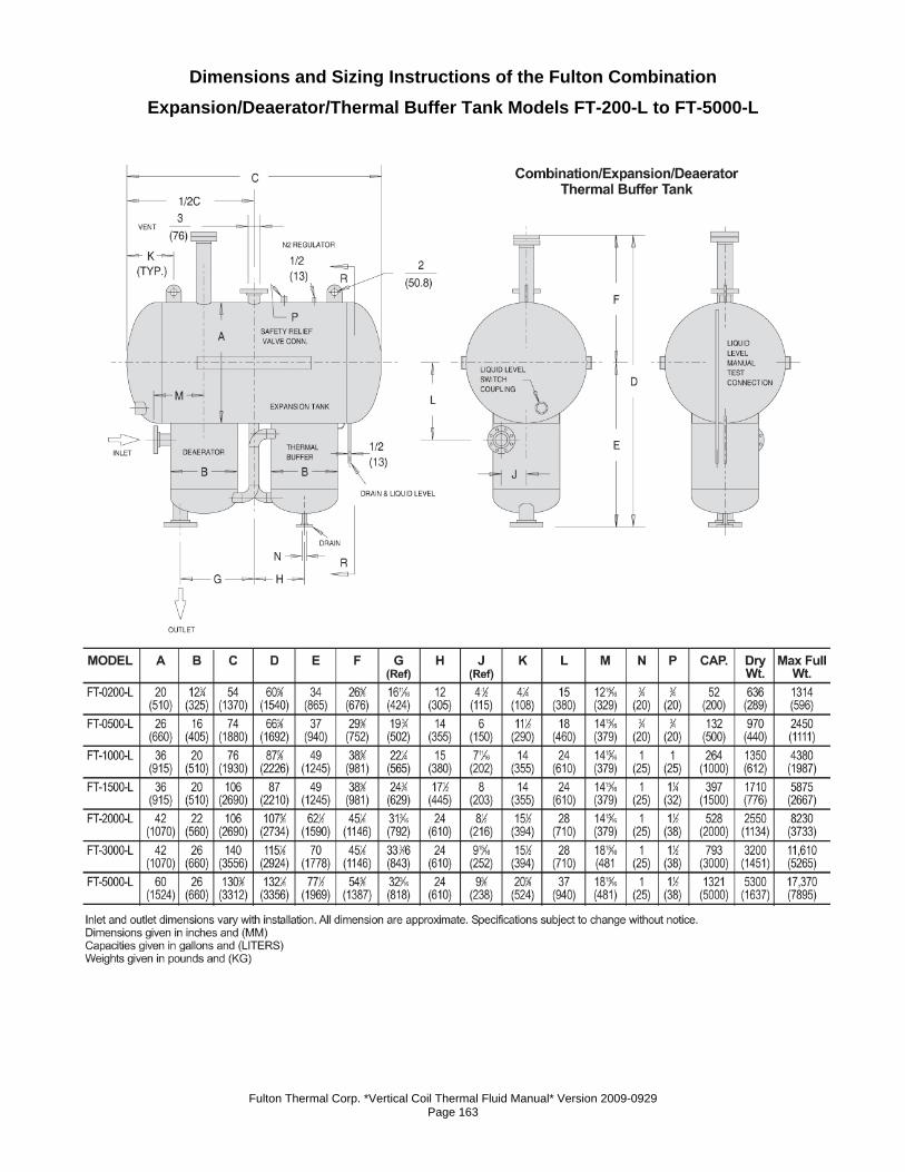
Fulton Thermal Corp. *Vertical Coil Thermal Fluid Manual* Version 2009-0929 Page 163
Dimensions and Sizing Instructions of the Fulton Combination Expansion/Deaerator/Thermal Buffer Tank Models FT-200-L to FT-5000-L
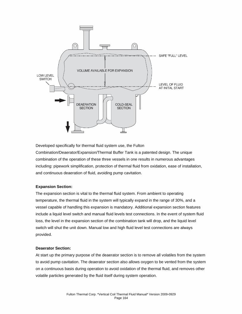
Fulton Thermal Corp. *Vertical Coil Thermal Fluid Manual* Version 2009-0929 Page 164
Developed specifically for thermal fluid system use, the Fulton
Combination/Deaerator/Expansion/Thermal Buffer Tank is a patented design. The unique
combination of the operation of these three vessels in one results in numerous advantages
including: pipework simplification, protection of thermal fluid from oxidation, ease of installation,
and continuous deaeration of fluid, avoiding pump cavitation.
Expansion Section: The expansion section is vital to the thermal fluid system. From ambient to operating
temperature, the thermal fluid in the system will typically expand in the range of 30%, and a
vessel capable of handling this expansion is mandatory. Additional expansion section features
include a liquid level switch and manual fluid levels test connections. In the event of system fluid
loss, the level in the expansion section of the combination tank will drop, and the liquid level
switch will shut the unit down. Manual low and high fluid level test connections are always
provided.
Deaerator Section: At start up the primary purpose of the deaerator section is to remove all volatiles from the system
to avoid pump cavitation. The deaerator section also allows oxygen to be vented from the system
on a continuous basis during operation to avoid oxidation of the thermal fluid, and removes other
volatile particles generated by the fluid itself during system operation.
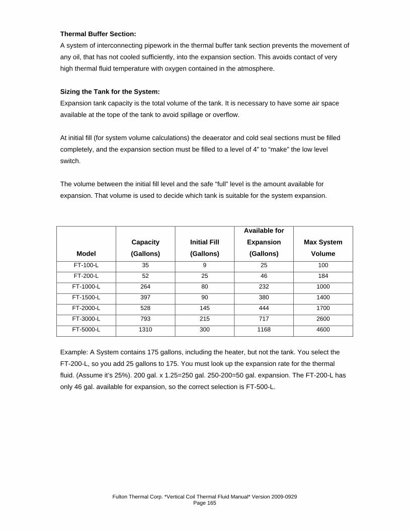
Fulton Thermal Corp. *Vertical Coil Thermal Fluid Manual* Version 2009-0929 Page 165
Thermal Buffer Section: A system of interconnecting pipework in the thermal buffer tank section prevents the movement of
any oil, that has not cooled sufficiently, into the expansion section. This avoids contact of very
high thermal fluid temperature with oxygen contained in the atmosphere.
Sizing the Tank for the System: Expansion tank capacity is the total volume of the tank. It is necessary to have some air space
available at the tope of the tank to avoid spillage or overflow.
At initial fill (for system volume calculations) the deaerator and cold seal sections must be filled
completely, and the expansion section must be filled to a level of 4” to “make” the low level
switch.
The volume between the initial fill level and the safe “full” level is the amount available for
expansion. That volume is used to decide which tank is suitable for the system expansion.
Model Capacity (Gallons)
Initial Fill (Gallons)
Available for Expansion (Gallons)
Max System Volume
FT-100-L 35 9 25 100
FT-200-L 52 25 46 184
FT-1000-L 264 80 232 1000
FT-1500-L 397 90 380 1400
FT-2000-L 528 145 444 1700
FT-3000-L 793 215 717 2600
FT-5000-L 1310 300 1168 4600
Example: A System contains 175 gallons, including the heater, but not the tank. You select the
FT-200-L, so you add 25 gallons to 175. You must look up the expansion rate for the thermal
fluid. (Assume it’s 25%). 200 gal. x 1.25=250 gal. 250-200=50 gal. expansion. The FT-200-L has
only 46 gal. available for expansion, so the correct selection is FT-500-L.
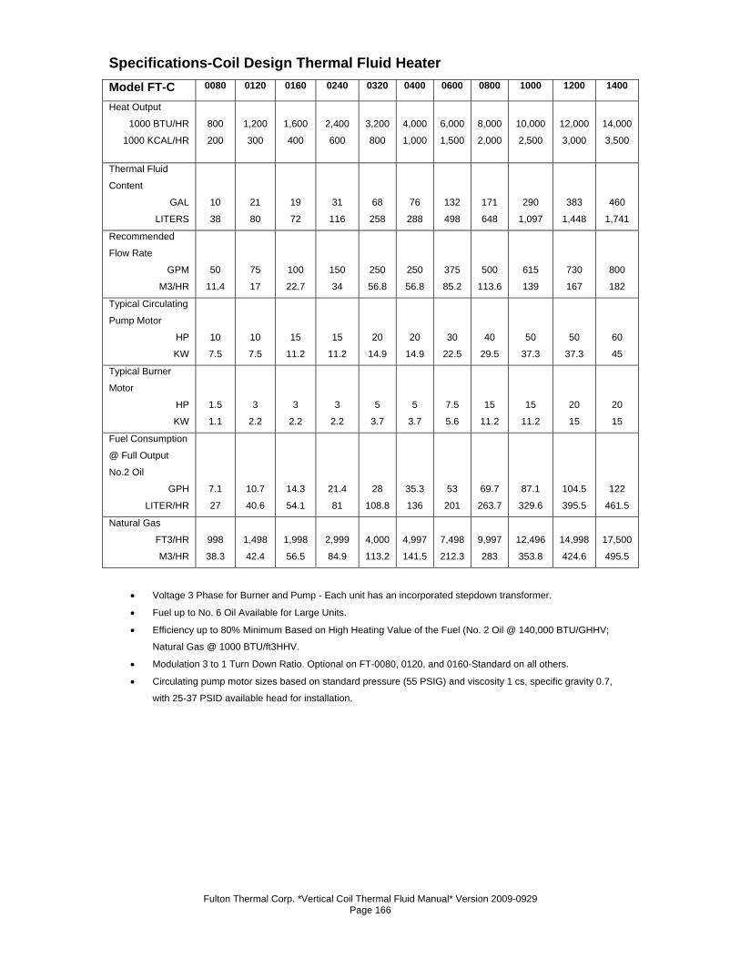
Fulton Thermal Corp. *Vertical Coil Thermal Fluid Manual* Version 2009-0929 Page 166
Specifications-Coil Design Thermal Fluid Heater Model FT-C 0080 0120 0160 0240 0320 0400 0600 0800 1000 1200 1400
Heat Output
1000 BTU/HR
1000 KCAL/HR
800
200
1,200
300
1,600
400
2,400
600
3,200
800
4,000
1,000
6,000
1,500
8,000
2,000
10,000
2,500
12,000
3,000
14,000
3,500
Thermal Fluid
Content
GAL
LITERS
10
38
21
80
19
72
31
116
68
258
76
288
132
498
171
648
290
1,097
383
1,448
460
1,741
Recommended
Flow Rate
GPM
M3/HR
50
11.4
75
17
100
22.7
150
34
250
56.8
250
56.8
375
85.2
500
113.6
615
139
730
167
800
182
Typical Circulating
Pump Motor
HP
KW
10
7.5
10
7.5
15
11.2
15
11.2
20
14.9
20
14.9
30
22.5
40
29.5
50
37.3
50
37.3
60
45
Typical Burner
Motor
HP
KW
1.5
1.1
3
2.2
3
2.2
3
2.2
5
3.7
5
3.7
7.5
5.6
15
11.2
15
11.2
20
15
20
15
Fuel Consumption
@ Full Output
No.2 Oil
GPH
LITER/HR
7.1
27
10.7
40.6
14.3
54.1
21.4
81
28
108.8
35.3
136
53
201
69.7
263.7
87.1
329.6
104.5
395.5
122
461.5
Natural Gas
FT3/HR
M3/HR
998
38.3
1,498
42.4
1,998
56.5
2,999
84.9
4,000
113.2
4,997
141.5
7,498
212.3
9,997
283
12,496
353.8
14,998
424.6
17,500
495.5
• Voltage 3 Phase for Burner and Pump - Each unit has an incorporated stepdown transformer.
• Fuel up to No. 6 Oil Available for Large Units.
• Efficiency up to 80% Minimum Based on High Heating Value of the Fuel (No. 2 Oil @ 140,000 BTU/GHHV;
Natural Gas @ 1000 BTU/ft3HHV.
• Modulation 3 to 1 Turn Down Ratio. Optional on FT-0080, 0120, and 0160-Standard on all others.
• Circulating pump motor sizes based on standard pressure (55 PSIG) and viscosity 1 cs, specific gravity 0.7,
with 25-37 PSID available head for installation.
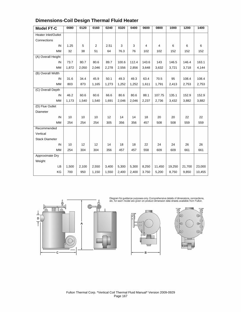
Fulton Thermal Corp. *Vertical Coil Thermal Fluid Manual* Version 2009-0929 Page 167
Dimensions-Coil Design Thermal Fluid Heater Model FT-C 0080 0120 0160 0240 0320 0400 0600 0800 1000 1200 1400
Heater Inlet/Outlet
Connections
IN
MM
1.25
32
5
38
2
51
2.51
64
3
76.3
3
76
4
102
4
102
6
152
6
152
6
152
(A) Overall Height
IN
MM
73.7
1,872
80.7
2,050
80.6
2,046
89.7
2,278
100.6
2,556
112.4
2,856
143.6
3,648
143
3,632
146.5
3,721
146.4
3,718
163.1
4,144
(B) Overall Width
IN
MM
31.6
803
34.4
873
45.9
1,165
50.1
1,273
49.3
1,252
49.3
1,252
63.4
1,611
70.5
1,791
95
2,413
108.4
2,753
108.4
2,753
(C) Overall Depth
IN
MM
46.2
1,173
60.6
1,540
60.6
1,540
66.6
1,691
80.6
2,046
80.6
2,046
88.1
2,237
107.75
2,736
135.1
3,432
152.9
3,882
152.9
3,882
(D) Flue Outlet
Diameter
IN
MM
10
254
10
254
10
254
12
305
14
356
14
356
18
457
20
508
20
508
22
559
22
559
Recommended
Vertical
Stack Diameter
IN
MM
10
254
12
304
12
304
14
356
18
457
18
457
22
558
24
609
24
609
26
661
26
661
Approximate Dry
Weight
LB
KG
1,500
700
2,100
950
2,550
1,150
3,400
1,550
5,300
2,400
5,300
2,400
8,250
3.750
11,450
5,200
19,250
8,750
21,700
9,850
23,000
10,455
Fulton Thermal Corp. *Vertical Coil Thermal Fluid Manual* Version 2009-0929 Page 168

Fulton Thermal Corp. *Vertical Coil Thermal Fluid Manual* Version 2009-0929 Page 169

Fulton Thermal Corp. *Vertical Coil Thermal Fluid Manual* Version 2009-0929 Page 170

Fulton Thermal Corp. *Vertical Coil Thermal Fluid Manual* Version 2009-0929 Page 171
Fulton Thermal Corp. *Vertical Coil Thermal Fluid Manual* Version 2009-0929 Page 172
No part of this Installation, Operation, and Maintenance manual may be reproduced in any form or by any means without permission in writing from the Fulton Companies.
Fulton Boiler Works, Inc., Fulton Heating Solutions, Inc. & Fulton Thermal Corporation are part of the Fulton Group of
Companies, a global manufacturer of steam, hot water and thermal fluid heat transfer systems.