full expandable model of parallel self-excited...
TRANSCRIPT

Full expandable model of parallel self-excitedinduction generators
F.A. Farret, B. Palle and M.G. Sim *oes
Abstract: Self-excited induction generators (SEIG) offer many advantages as variable-speedgenerators in renewable energy systems. Small hydro and wind generating systems have constraintson the size of individual machines, and several induction generators must be paralleled in order toaccess fully the potential of the site. SEIGs connected in parallel may lose excitation momentarilyowing to large transient currents caused by differences in individual instantaneous voltages andfrequency. This phenomenon cannot be easily simulated using the conventional models because ithas such a fast transient nature. An innovative and automatic numerical solution for steady-stateand transient analysis of any number of SEIGs operating in parallel is presented. Experimentalresults confirm the accuracy of the proposed model and open new possibilities for incorporatingadvanced control to monitor and optimise a parallel installation of SEIGs. The proposed SEIGmodel is applied to a two-turbine case, which can be extended to simulate a wind generatingsystem.
1 Introduction
There has been a huge increase in energy demand, duringthe last few decades, which has accelerated the depletion ofworld fossil fuel supplies. Environmental concerns andinternational policies are supporting new interests anddevelopments for small-scale power generation. Therefore,the study of self-excited induction generators has regainedimportance, as they are particularly suitable for wind andsmall hydro power plants [1, 2]. They have advantages overconventional synchronous generators in their reducedinstallation cost, lower maintenance requirements, absenceof power supply for excitation and natural protectionagainst system faults. The applications of self-excitedinduction generators (SEIGs) are limited, based oneconomic reasons depending on the combined costs ofmachine, excitation capacitors and static switches. TypicalSEIG loads include electricity for rural residences [3],heating, lighting and small induction motors. Typically,generators rated 15kVA are cost effective; but 100kVA [4]was found to be the upper limit where generator price is inthe crossover price curve.
A stand-alone SEIG is unlikely to supply the energydemand of ordinarily growing loads for a long time. Thus,multiple generators operating in parallel may be required toharvest the maximum energy available at a site. Also, in thelast few years, the trend has changed from installing a fewwind turbines to planning large wind farm installations withmany induction generators connected electrically in parallel[5, 6]. With increasing penetration of wind power intopower networks, an accurate dynamic model of the overall
wind farm system is required to analyse the interactionbetween the wind farm and the power system. A system ofparallel-operated SEIGs, in a wind or small hydro powerplant, is subjected to various transient conditions, such asinitial self-excitation, load transient and generator/capacitorswitching. Transient interaction and resonant states mayalso be reasons for concern, in small power plants, as theymay create unstable oscillations, cause mechanical elementsdeterioration and trigger protection circuits. Therefore, it isimportant to perform modelling and simulation analysis ofparallel-operated induction generators under transientconditions. References [7–9] developed a wind farm modelthat can be used in power system dynamic simulations withsteady-state representation of the generator, and do not dealwith the transient behaviour of SEIGs. Several papers [10–14] have been published on stand-alone operation of self-excited generators, but only a few references are availableon parallel operation of SEIGs. Steady-state analysis ofparallel-operated SEIGs has been discussed [15, 16], butprevious work related to transient analysis does not presentclear numerical modelling and experimental observations[17, 18]. The current literature does not approach paralleloperation under transient analysis with limitations due toapproximated representation of the induction machinemodels.
In this paper, an automatic procedure to build up amatrix model for steady-state and transient analysisFvalidfor any number of self-excited induction generatorsoperating in parallel and supplying a common R–LloadFis proposed [19]. Figure 1 shows n induction
loadC1
G1
C2
. . . . . .. . . . . .
. . . . . .. . . . . .
G2
Cn
Gn
Fig. 1 Induction machines supplying a common load
F.A. Farret is with the Federal University of Santa Maria, Rua Dr Bozano, 915Apto. 203, Santa Maria – RS 97.015.003, Brazil
B. Palle and M.G. Sim*oes are with the Colorado School of Mines, 1610 IllinoisSt., Golden, Colorado 80401-1887, USA
r IEE, 2005
IEE Proceedings online no. 20045057
doi:10.1049/ip-epa:20045057
Paper first received 12th June and in revised form 22nd October 2004
96 IEE Proc.-Electr. Power Appl., Vol. 152, No. 1, January 2005

machines ready to be connected in parallel according toload requirements or when more energy becomes available.Such a basic association of generators seems to cope withthe vast majority of practical cases since it is alwaysexpected to have a new generator connected or disconnectedfrom an already existing parallel association. It should benoted that each machine needs a self-excitation capacitance,because each machine has its own magnetisation curve.
A computer algorithm is developed to simulate theparallel operation of SEIGs. Simulated results for connec-tion of two generators are compared with experimentalresults on two laboratory machines. Individual variation inthe magnetising inductance is incorporated in the analysis.A model is then developed for a wind turbine with an SEIGas the AC generator. Parallel operation of two windturbines is simulated using real wind conditions. This modelallows us to reproduce several conditions encountered insmall power plants.
2 Model for parallel SEIGs
The model to be presented accords with the representationof n SEIGs as shown in Fig. 1. A generalised state–spaceequation for n generators operating in parallel is shown in(1). Generator, excitation capacitance and load parametersof the generation system are separated to obtain a matrixrepresentation of parallel generators in a wind or a hydropower plant. Incoming generators can be incorporated intothe model by appending the generator matrix ‘G’ diag-onally, as shown. This matrix representation allows us tosimulate the behavior of n generators in parallel during theself-excitation process and in the steady state. It also allowsus to analyse the transient performance under varying loadconditions and generator switching. Eigenvalue and eigen-vector analysis can also be performed using (1), as it is in theform of the classical state–space equation. A detailed SEIGmodel is developed in Section 3:
p
iG1
iG2
..
.
iGn
vL
iL
26666666664
37777777775¼
G1 0 � � � L1
0 G2 L2
..
. . .. ..
.
Gn Ln
CG CG � � � CG CT
0 0 0 0 L
26666666664
37777777775
iG1
iG2
..
.
iGn
vL
iL
26666666664
37777777775þ
B1
B2
. ..
Bn
0 0 0 0
266666664
377777775
vG1
vG2
..
.
vGn
266664
377775
ð1Þ
where
iGi ¼
idsi
iqsi
idri
iqri
2664
3775; vGi ¼
vdsi
vqsi
vdri
vqri
2664
3775; vL ¼
vLd
vLq
� �; iL ¼
iLd
iLq
� �
3 SEIG modelling
Through (3) and Fig. 2, a classic matrix formulation [20]using d–q axis modelling is used to represent the dynamicsof a conventional induction machine operating as agenerator. For an isolated generator, the parameters arelabelled according to Fig. 2. The representation includes theself and mutual inductances as coefficients widely used inmachine theory. Using such a matrix representation, onecan obtain the instantaneous voltages and currents duringthe self-excitation process, as well as during load variations.At this point, it must be said that the traditional d–q axismodel is not convenient for the automatic building up of ageneral model of parallel-operated induction generators,because it does not isolate the machine parameters from theself-excitation capacitor and load parameters. To isolatethose parameters, (4) has been formulated using eight first-order differential equations that relate the stator and rotorcurrents and voltages. The simultaneous solution of thissystem of equations can be obtained using the Runge–Kutta fourth-order integration method with automaticadjustment of step. This gives the instantaneous values of d–q axis voltages and currents for stator and rotor.
The following assumptions are made in this analysis:(i) Core and mechanical losses in the machines are
neglected. (ii) All machine parameters, except the magnetiz-ing inductance, are assumed to be constant. (iii) Statorwindings, self-excitation capacitors and the load are wyeconnected. The variation of the magnetizing inductance isthe main factor in the dynamics of the voltage build up andstabilization in SEIGs. When multiple SEIGs are operatingin parallel, the machine with the lowest saturation voltagewill control the voltage of the whole group. So, withmachines of different ratings, the larger machines will haveto be de-rated so as to stop them driving the smallermachines. The relationship between magnetization induc-tance, Lm, and the magnetization current for each inductionmachine was obtained experimentally. The non-linearrelationship between magnetising inductance and magnetis-ing current for the generator G1 (see Section 5) used in theexperimental setup is shown below:
Lm ¼ �6:89� 10�6I4m þ 1:38� 10�4I3m � 1:22
� 10�3I2m þ 1:28� 10�3Im þ 4:62� 10�2H ð2Þ
iqdr1 iqdr2
Lm1 Lm2
LIs1LIr1 LIs2 LIr2Rr1 +− + −iqds1 iqds1
Rs1
CR
L
Rs2 Rr2
jωr2�qdr2
�qdr1 �qds1 �qds2 �qdr2
SEIG1
excitationcapacitance
SEIG2load
jωr1�qdr1
Fig. 2 Two self-excited induction generators in parallel represented in d–q model
..........................................
..........................................
....................................
.....
.....
IEE Proc.-Electr. Power Appl., Vol. 152, No. 1, January 2005 97

vds
vqs
vdr
vqr
26664
37775 ¼
Rs þ Lsp þ RþLpRCpþLCp2þ1
� �0
Lmp
�orLm
266664
0 Lmp 0
Rs þ Lsp þ RþLpRCpþLCp2þ1
� �0 Lmp
orLm Rr þ Lrp orLr
Lmp �orLr Rr þ Lrp
377775
ids
iqs
idr
iqr
26664
37775
ð3ÞEquation (3) can be expressed as a state variable matrix thattakes the following form:
p
ids
iqs
idr
iqr
vLd
vLq
iLd
iLq
266666666666664
377777777777775
¼Kf
RsLr �orL2m �RrLm �orLmLr
orL2m RsLr orLmLr �RrLm
�RsLm orLmLs RrLs orLsLr
�orLmLs �RsLm �orLsLr RrLs
1=CK 0 0 0
0 1=CK 0 0
0 0 0 0
0 0 0 0
266666666666664
Lr 0 0 0
0 Lr 0 0
�Lm 0 0 0
0 �Lm 0 0
0 0 �1=CK 0
0 0 0 �1=CK
1=LK 0 �R=LK 0
0 1=LK 0 �R=LK
377777777777775
ids
iqs
idr
iqr
vLd
vLq
iLd
iLq
266666666666664
377777777777775
þ
�Lr 0 Lm 0
0 �Lr 0 Lm
Lm 0 �Ls 0
0 Lm 0 �Ls
0 0 0 0
0 0 0 0
0 0 0 0
0 0 0 0
377777777777775
vds
vqs
vdr
vqr
26664
37775g ð4Þ
which is in the form of classical state-space equationp[x]¼ [A][x]+[B][u], or:
piGvC
iL
24
35 ¼
GCL
24
35 iG
vC
iL
24
35þ B½ � vG½ � ð5Þ
where G, C and L refer, respectively, to the partition ofmatrix [A] into matrices for the induction generatorparameters, the self-excitation capacitance and the load.
Vector [x] is the transposed matrix [iG vC iL], and the sub-matrixes [G], [C] and [L] are defined as:
½G� ¼K
RsLr �orL2m �RrLm
orL2m RsLr �orLmLr
�RsLm orLmLs RrLs
�orLmLs �RsLm �orLsLr
26664
orLmLr Lr 0 0 0
�RrM 0 Lr 0 0
orLsLr �Lm 0 0 0
RrLs 0 �Lm 0 0
37775
½C�¼ CG Cr½ � ¼1=C 0 0 0 0 0 1=C 0
0 1=C 0 0 0 0 0 1=C
� �
½L� ¼0 0 0 0 1=L 0 �R=L 0
0 0 0 0 0 1=L 0 �R=L
� �
and K ¼ 1=L2m � LsLr
The excitation vector [u]¼ [vG] of (5) is multiplied by theexcitation parameter matrix [B] shown below. Therefore,[B][u] defines the voltages corresponding to the residualmagnetism in the machine core:
½B� ¼
�Lr 0 Lm 00 �Lr 0 Lm
Lm 0 �Ls 00 Lm 0 �Ls
0 0 0 00 0 0 00 0 0 00 0 0 0
266666666664
377777777775
Figure 3 shows the experimental and simulated plots of thetransient self-excitation process of a stand-alone SEIG.Load is switched on at 7.6 s. The induction generator wasoperated at 1780 rpm with a DC motor as prime mover. Acapacitor bank of 160mF in star connection supplied about700 VAR/phase of reactive power for the machine, and a120O–22.5mH star load was connected after the generatorwas completely excited. Variation of speed observed in thelaboratory when load was applied is incorporated in thenumerical simulation seen in Fig. 3a, which depictssimulated and approximated shaft speed. Remanentmagnetism in the machine core is also taken into accountand is explained in Section 4. The complete simulationprocess is detailed in the following sections.
Figure 4 shows an SEIG connected in star with anexcitation capacitor bank with neutrals isolated. The naturalconsequence of this type of connection is third harmonics inphase voltages. Simulation and experimental results do notshow any significant third-harmonic content as the machinewas run under light saturation. High currents can flowthrough the capacitors when run under deep saturation.Also, the excitation capacitor along with the machineinductance acts as lowpass filter attenuating the third-harmonic voltages present in the phase voltages. Figure 5
1600
1700
1800
−100
0
100
0 1 2 3 4 5 6 7 8 9
−100
0
100
a
b
ctime,s
phas
e vo
ltage
, Vro
tor s
peed
, rp
m simulatedspeed profile
approximatedshaft speed
Fig. 3 Self-excitation and load response of a stand alone SEIGa Rotor speed profileb Variation in phase voltage measured during self-excitation and loadswitching on generator G1 (see Section 5)c Variation in phase voltage simulated using MATLAB
............................................................
............................................................
................................................
......
......
........................................................................
........................................................................................................................
.........................................
.........................................
.........................................
.........................................
......................
.........
.........
98 IEE Proc.-Electr. Power Appl., Vol. 152, No. 1, January 2005
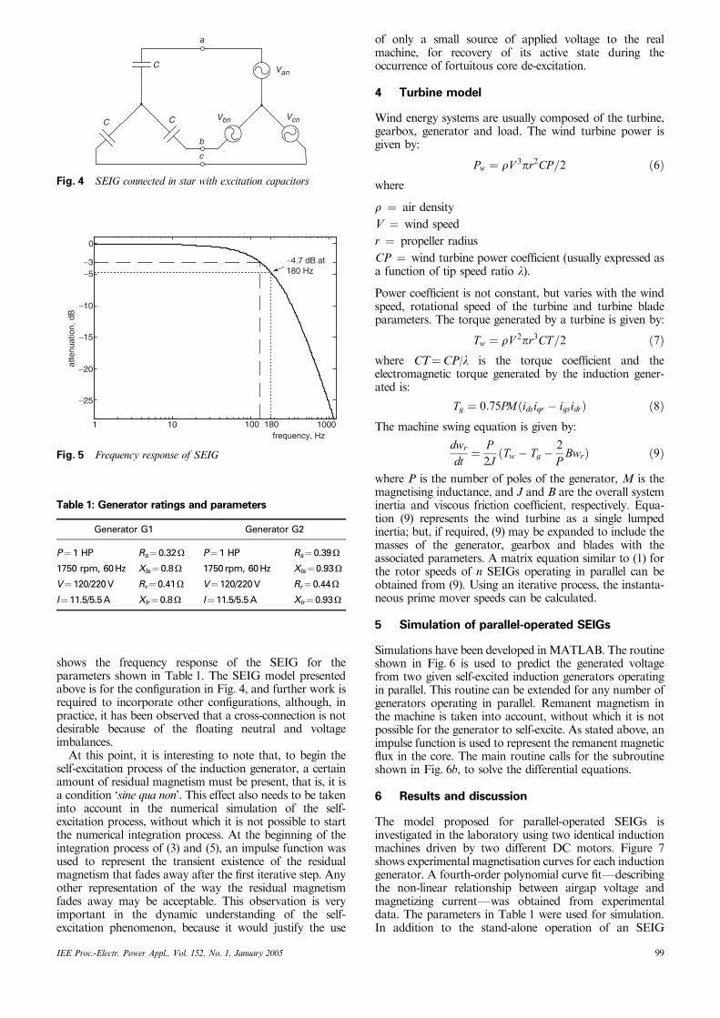
shows the frequency response of the SEIG for theparameters shown in Table 1. The SEIG model presentedabove is for the configuration in Fig. 4, and further work isrequired to incorporate other configurations, although, inpractice, it has been observed that a cross-connection is notdesirable because of the floating neutral and voltageimbalances.
At this point, it is interesting to note that, to begin theself-excitation process of the induction generator, a certainamount of residual magnetism must be present, that is, it isa condition ‘sine qua non’. This effect also needs to be takeninto account in the numerical simulation of the self-excitation process, without which it is not possible to startthe numerical integration process. At the beginning of theintegration process of (3) and (5), an impulse function wasused to represent the transient existence of the residualmagnetism that fades away after the first iterative step. Anyother representation of the way the residual magnetismfades away may be acceptable. This observation is veryimportant in the dynamic understanding of the self-excitation phenomenon, because it would justify the use
of only a small source of applied voltage to the realmachine, for recovery of its active state during theoccurrence of fortuitous core de-excitation.
4 Turbine model
Wind energy systems are usually composed of the turbine,gearbox, generator and load. The wind turbine power isgiven by:
Pw ¼ rV 3pr2CP=2 ð6Þwhere
r ¼ air density
V ¼ wind speed
r ¼ propeller radius
CP ¼ wind turbine power coefficient (usually expressed asa function of tip speed ratio l).
Power coefficient is not constant, but varies with the windspeed, rotational speed of the turbine and turbine bladeparameters. The torque generated by a turbine is given by:
Tw ¼ rV 2pr3CT=2 ð7Þwhere CT¼CP/l is the torque coefficient and theelectromagnetic torque generated by the induction gener-ated is:
Tg ¼ 0:75PMðidsiqr � iqsidrÞ ð8ÞThe machine swing equation is given by:
dwr
dt¼ P
2JðTw � Tg �
2
PBwrÞ ð9Þ
where P is the number of poles of the generator, M is themagnetising inductance, and J and B are the overall systeminertia and viscous friction coefficient, respectively. Equa-tion (9) represents the wind turbine as a single lumpedinertia; but, if required, (9) may be expanded to include themasses of the generator, gearbox and blades with theassociated parameters. A matrix equation similar to (1) forthe rotor speeds of n SEIGs operating in parallel can beobtained from (9). Using an iterative process, the instanta-neous prime mover speeds can be calculated.
5 Simulation of parallel-operated SEIGs
Simulations have been developed inMATLAB. The routineshown in Fig. 6 is used to predict the generated voltagefrom two given self-excited induction generators operatingin parallel. This routine can be extended for any number ofgenerators operating in parallel. Remanent magnetism inthe machine is taken into account, without which it is notpossible for the generator to self-excite. As stated above, animpulse function is used to represent the remanent magneticflux in the core. The main routine calls for the subroutineshown in Fig. 6b, to solve the differential equations.
6 Results and discussion
The model proposed for parallel-operated SEIGs isinvestigated in the laboratory using two identical inductionmachines driven by two different DC motors. Figure 7shows experimental magnetisation curves for each inductiongenerator. A fourth-order polynomial curve fitFdescribingthe non-linear relationship between airgap voltage andmagnetizing currentFwas obtained from experimentaldata. The parameters in Table 1 were used for simulation.In addition to the stand-alone operation of an SEIG
1 10
−4.7 dB at180 Hz
frequency, Hz
atte
nuat
ion,
dB
100 180 1000
−25
−20
−15
−10
−5−3
0
Fig. 5 Frequency response of SEIG
Table 1: Generator ratings and parameters
Generator G1 Generator G2
P¼1 HP Rs¼ 0.32O P¼1 HP Rs¼0.39O
1750 rpm, 60Hz Xls¼ 0.8O 1750rpm, 60Hz Xls¼ 0.93O
V¼120/220V Rr¼ 0.41O V¼ 120/220V Rr¼0.44O
I¼11.5/5.5A Xlr¼ 0.8O I¼ 11.5/5.5A Xlr¼ 0.93O
a
b
c
C
CC
Van
VcnVbn
Fig. 4 SEIG connected in star with excitation capacitors
IEE Proc.-Electr. Power Appl., Vol. 152, No. 1, January 2005 99

supplying a medium load discussed in Section 3, four othercases have been discussed in this paper:
� voltage collapse in a stand-alone self-excited inductiongenerator due to a heavy load
� transient phenomena of load and generator switching oftwo SEIGs operating at different voltages levels
� transient phenomena of load and generator switching oftwo SEIGs operating at similar voltage levels
� simulation of two wind turbines using real wind dataoperating electrically in parallel.
Figure 8 shows the experimental and simulated plots ofterminal voltage collapse of a stand-alone SEIG underapplication of a heavy R–L load at time¼ 2.6 s. GeneratorG1 was self-excited with 160mF capacitance bank, and a45O–45.5mH star load was applied after the generator wasfully excited. Speed variations observed in the laboratorywere taken into account for simulation, as illustrated inFig. 8a. It took about 2.5 s for the voltage to collapsecompletely. To avoid the collapse, an electronic protectionscheme can be used to detect the current levels. If thecollapse occurs, the machine has to be re-magnetised.
Figure 9 shows the transient process of load andgenerator switching of two SEIGs operating in parallel.Generator G1 was self-excited with 160mF capacitance at1800 rpm, and a 130O–22.5mH star-connected load wasapplied at time¼ 2 s. Generator G2 was previously self-excited with 160mF at 1800 rpm, and connected in parallelat time¼ 3.75 s. The sudden and brief collapse in voltage isdue to differences in phase voltage of the two generators, atthe paralleling instant. Full common voltage was recoveredat about time¼ 6.0 s. The rotor speed variation ofgenerators G1 and G2, during parallel operation, wascarefully observed in the laboratory and was incorporatedin the simulation, as illustrated in Fig. 9a. At the precise
start
start
if itr < max_itr
itr = itr + 1 if itr > 1
end
solve the state-space equation for the d-q parameters using Runge-
Kutta fourth order method
remove the initialimpulse applied
for residualmagnetism
record instantaneousgenerator phase
voltages
calculate the magnetization currentand update mutual inductance
Y
Y
N
N
read machine parameters,magnetizationcharacteristics
initialize residual magnetism; set itr = 0
simulate stand-alone operation of generator-1using the sub-routine in fig. 4(b)
simulate stand-alone operation of generator-2using the sub-routine in fig. 4(b)
close the paralleling switch at the chosen instant
simulate stand-alone operation of two generatorsusing the sub-routine in fig. 4(b)
switch load when generatoris completely excited
a
b
Fig. 6a Main program to simulate parallel operationb Sub-routine for numerical solution
1400
1600
1800
−100
0
100
0 1 2 3 4 5 6
−100
0
100
roto
r sp
eed,
rp
mph
ase
volta
ge, v
approximatedshaft speed
simulatedspeed profile
a
b
ctime, s
Fig. 8 Voltage collapse in a stand-alone SEIG under heavy loada Rotor speed profileb Variation in phase voltage measured during collapse of G1c Variation in phase voltage simulated
0
20
40
60
80
100
120
14 0
160
0 2 4 6 8 10
G2
G1
Im, A
Vg
, V
Fig. 7 Magnetisation characteristics of generators G1 and G2
100 IEE Proc.-Electr. Power Appl., Vol. 152, No. 1, January 2005

instant of parallel connection of the two generators, a heavydip in the overall speed of the machines was noticed.
Three moments should be pointed out in those graphs.The first is related to the voltage reduction across generatorG1’s terminals when the R–L load was switched on. Thesecond is the partial voltage collapse at time¼ 3.85 s, and itsrecovery up to the parallel common voltage level at about6.0 s. The third moment to observe is the reduced voltage ofgenerators G1 and G2 with respect to the no-load voltagelevel of G2 alone representing an appreciable voltagedifference at the parallel connecting instant. These threemoments can be clearly and closely observed in boththeoretical and experimental setups. Synchronisation tech-niques could be included so as to switch the generatorswhen the phase voltages are in phase. The purpose of thisresult was to demonstrate the possibility of representing theworst-case scenario using the proposed model.
Figure 10 shows the experimental and simulated plots oftransient generator switching process when parallel connec-tion was made between SEIGs operating at identical voltagelevels. Generator G1 was self-excited with 180mF capaci-tance, and a 130O–22.5mH star load was applied attime¼ 1.2 s. Generator G2 was already self-excited with160mF and was connected in parallel at time¼ 4.4 s. Fullcommon voltage was recovered at about time¼ 5.2 s. As thevoltages were similar, there was no collapse as observed inthe previous case, and the voltage and speed dips were notvery pronounced.
Figure 11 shows the simulated plots of two 20kW windturbines operating electrically in parallel. Figure 11a showsthe wind speed profile of the two turbines. The generatorbegins to self-excite after the rotor has reached a certainspeed (1). As the wind speed increases, the generated voltagealso increases (2). The dip in voltage at (3) corresponds toload switching. G2 is connected to G1 at (4) to share theload, resulting in a slight increase in the G1 voltage.
Figure 12 shows the simulated rotor speed and torquevariations during load and generator switching process. Thetorque surge experienced by the two machines, during theswitching of the second generator, is very high. However, itsettled down in a few milliseconds; therefore, the system isable to sustain its excitation.
7 Conclusions
An innovative model to simulate the electromechanicalsteady-state and transient performance of any number ofwind turbines with induction generators connected inparallel has been presented. With this model, it is possibleto have an automatic computer process to generate the statevariable matrix representing the incorporation of any newwind turbine to the previous parallel association. Thisfeature is guaranteed by the separate parameter representa-tion of the machine model, the self-excitation bank ofcapacitors and the load.
The approach presented enhances previous work basedonly on electrical steady-state conditions that could not beused for real analysis of the transient phenomenon thatoccurs and may have adverse impact on system stability and
roto
r sp
eed,
rpm
phas
e vo
ltage
, v
a
b
c
d
simulatedspeed profile
approximated shaft speed
1200
1600
−1000
100
−1000
100
0 1 2 3 4 5 6 7 8 9
−1000
100
time, s
Fig. 10 Parallel connection of two SEIGs with similar voltagelevelsa Rotor speed profileb Variation in phase voltage of G1measured. Load applied at t¼ 1.2 s,and paralleling switch is closed at t¼ 4.6 sc Simulated variation in phase voltage of G1d Simulated variation in phase voltage of G2
roto
r sp
eed,
rpm
phas
e vo
ltage
, v
c
d
b
a
time, s
0 1 2 3 4 5 6 7 8 9
80012001600
−100
0
100
−100
0
100
−100
0
100
approximatedshaft speed
simulatedspeed profile
Fig. 9 Parallel connection of two SEIGs with different voltagelevelsa Rotor speed profileb Variation in phase voltage of G1 measured. Load applied att¼ 1.95 s, and paralleling switch closed at t¼ 3.85 sc Simulated variation in phase voltage of G1d Simulated variation in phase voltage of G2
win
d sp
eed,
m/s
vw1 vw2
phas
e vo
ltage
, v
c
b
a
1 2 3
4
time, s
5
6
7
−500
0
500
0 5 10 15 20 25 30 35 40 45 50−500
0
500
Fig. 11 Simulation of two wind turbines operating in parallela Wind speed profileb Simulated phase voltage of G1. Load applied at t¼ 36 s, andparalleling switch closed at t¼ 38 sc Simulated phase voltage of G2
IEE Proc.-Electr. Power Appl., Vol. 152, No. 1, January 2005 101

protection. Previous work related to transient analysis doesnot present clear numerical modelling and experimentalobservations. Experimental results prove that the proposedmatrix partition is in agreement with the mathematicalmodelling. In addition, the use of the matrix partitionproved to be a powerful numerical tool.
The main advantages of this approach are: (i) representa-tion of the self-excited induction generator in the form ofclassical state equations; (ii) separation of the machineparameters from the self-excitation capacitors and loadparameters, to allow the automatic building up of thematrix representation of SEIG parallel operation; (iii) anincrease of flexibility and simplicity in generalising a modelfor n parallel-operated generators; (iv) inclusion of electro-mechanical steady-state and transient analysis of theparalleling of induction generators; and (v) eigenvalues(eigenvector analysis can be performed using the classicalstate–space representation).
8 Acknowledgments
The authors sincerely thank the Coordination for Improve-ment of Advanced Education Personal (CAPES) and theNational Science Foundation (NSF) for their financialsupport of this project.
9 References
1 Chan, T.F., and Lai, L.L.: ‘A novel excitation scheme for a stand-alone three phase induction generator supplying single-phase loads’,IEEE Trans. Ind. Appl., 2004, 19, (1), pp. 136–143
2 Bansal, R.C., Bhatti, T.S., and Kothari, D.P.: ‘Bibliography on theapplication of induction generators in nonconventional energysystems’, IEEE Trans. Energy Convers., 2003, 18, (3), pp. 433–439
3 Marra, E.G., and Pomilio, J.A.: ‘Self-excited induction generatorcontrolled by a VS-PWM bidirectional converter for rural applica-tions’, IEEE Trans. Ind. Appl., 1999, 35, (4), pp. 877–833
4 Elder, J.M., Boys, J.T., and Woodward, J.L.: ‘Self-excited inductionmachine as a small low-cost generator’, IEE Proc. C., 1984, 131, (1),pp. 33–41
5 Muljadi, E., Sallan, J., Sanz, M., and Butterfield, C.P.: ‘Investigationof self-excited generators for wind turbine applications’, Thirty-FourthIEEE IAS Annual Meeting, 1999, 1, pp. 509–515
6 de Mello, F.P., and Hannett, L.N.: ‘Large scale induction generatorsfor power systems’, IEEE Trans. Power Appar. Systems, 1981, 100, pp.2610–2618
7 Hansen, A.D., Sorensen, P., Janosi, L., and Bech, J.: ‘Windfarm modelling for power quality’. Proc. 27th Annual Conf. of theIEEE Industrial Electronics Society (IECON’01), 2001, Vol. 3,pp. 1959–1964
8 Feijoo, A.E., and Cidras, J.: ‘Modeling of wind farms in the load flowanalysis’, IEEE Trans. Power Syst., 2000, 15, (1), pp. 110–115
9 Slootweg, J.G., de Haan, S.W.H., Polinder, H., and Kling, W.L.:‘General model for representing variable speed wind turbines in powersystem dynamics simulations’, IEEE Trans. Power Sys., 2003, 18, (1),pp. 144–151
10 Seyoum, D., Grantham, C., and Rahman, F.: ‘The dynamiccharacteristics of an isolated self-excited induction generator drivenby a wind turbine’, IEEE Trans. Ind. Appli., 2003, 39, (4), pp. 936–944
11 Seyoum, D., Grantham, C., Rahman, F., and Nagrial, M.: ‘An insightinto the dynamics of loaded and free running isolated self-excitedinduction generators’. Proc. Int. Conf. on Power Electronics,Machines and Drives, University of Bath, UK, 2002, pp. 580–585
12 Wang, L., and Deng, R.-Y.: ‘Transient performance of an isolatedinduction generator under unbalanced excitation capacitors’, IEEETrans. Energy Conver., 1999, 14, (4), pp. 887–893
13 Alghuwainem, S.M.: ‘Steady state analysis of an isolated self-excitedinduction generator driven by regulated and unregulated turbine’,IEEE Trans. Energy Conver., 1999, 14, (3), pp. 718–723
14 Seyoum, D., Rahman, M.F., and Grantham, C.: ‘Terminal voltagecontrol of a wind turbine isolated induction generator usingstator oriented field control’. Proc. 18th Annual IEEE PowerElectronics Conference and Exposition, Miami Beach, Florida,USA, 2003, Vol. 2, pp. 846–852
15 Chakraborty, C., Bhadra, S.N., and Chattopadhyay, A.K.: ‘Analysisof parallel- operated self excited induction generators’, IEEE Trans.Energy Conver., 1999, 14, (2), pp. 209–216
16 Al-Bahrani, A.H., and Malik, N.H.: ‘Steady state analysis of paralleloperated self-excited induction generators’, IEE Proc., 1993, 140, (1),pp. 49–55
17 Wang, L., and Lee, C.-H.: ‘A novel analysis of parallel operated self-excited induction generators’, IEEE Trans. Energy Convers., 1998, 13,(2), pp. 117–123
18 Wang, L., and Lee, C.-H.: ‘Dynamic analysis of parallel operated self-excited induction generators feeding an induction motor load,’ IEEETrans. Energy Convers., 1999, 14, (3), pp. 479–485
19 Farret, F.A., Canha, L.V., Correa, J.M., and Reckziegel, M.: ‘Estudosobre a associa-c*ao de geradores de indu-c*ao auto excitados usandoespa-co de estados’. Proc. XII Brazilian Congress on Automation,Uberlandia, Brazil, 1998, Vol. 1, pp. 105–109
20 Hancock, N.N.: ‘Matrix Analysis of Electrical Machinery’ (PergamonPress, Oxford, New York, USA, 1974)
a
Tw1
Tw2
Tg1
Tg2
b
ctime, s
1000
15002000
0
10
20
0 5 10 15 20 25 30 35 40 45 500
10
20
ωr2 ωr1
torq
ue, N
mro
tor
spee
d, r
pm
Fig. 12 Simulation of two wind turbines operating in parallela Rotor speed profiles of two generatorsb Turbine torque and electromagnetic torque of G1c Turbine torque and electromagnetic torque of G2
102 IEE Proc.-Electr. Power Appl., Vol. 152, No. 1, January 2005