fuel operated inline pressure control valves - 3 & 4 …pub/@eaton/@aero/...sm64502 october 2012...
TRANSCRIPT
Aerospace Group Conveyance Systems Division Carter
® Brand Ground Fueling Equipment
SM64502
October 2012 Applicable addition manuals:
None
Maintenance & Repair Manual
Fuel Operated Inline Pressure Control Valves - 3 & 4 Inch
Models 64502 & 64512
SM64502 October 2012
2
Table of Contents
Page
1.0 Introduction .................................................................................................................... 3
2.0 Equipment Description ................................................................................................... 3
3.0 Table of Options and Ordering Information ................................................................... 3
4.0 Disassembly .................................................................................................................. 3
5.0 Inspection....................................................................................................................... 5
6.0 Reassembly ................................................................................................................... 5
7.0 Test ................................................................................................................................ 7
8.0 Illustrated Parts Catalog ................................................................................................ 8
FIGURE 1 - 3 & 4 Inch Fuel Operated In-Line Valve Illustration ............................................ 8
FIGURE 2 - Manifold Parts Breakdown .................................................................................. 9
Figure 3 - 3 Inch Valve Assembly ......................................................................................... 10
figure 4 - 4 Inch Valve Assembly .......................................................................................... 12
Figure 5A - Inner Piston Seal Installation - Older Units ........................................................ 14
Figure 5B - Inner Piston Seal Installation - Newer Units ...................................................... 14
Figure 6 - Outer Piston Seal Installation ............................................................................... 15
NOTE: The information in this manual is to the latest revision of the products listed above at the time of this
printing. Eaton reserves the right to change this manual at its discretion.
SM64502 October 2012
3
Maintenance, Overhaul & Test Instructions Models 64502 & 64512 3 & 4 Inch Fuel Operated Inline Pressure Control Valves
1.0 INTRODUCTION
This manual furnishes detailed instructions covering the maintenance and overhaul of Eaton’s Carter
® brand
Model 64502, 3 inch & Model 64512, 4 inch fuel operated
inline pressure control valves and the various options listed in Section 3.0.
2.0 EQUIPMENT DESCRIPTION
Models 64502 and 64512 are the latest versions of the 3 & 4 inch fuel operated inline pressure control valves that replace the older 64130 and 64140 models. Because they have many characteristics in common, a single manual is used to present both units.
The valves listed above are designed to provide a constant nominal pressure at a remote sense point using fuel pressure generated within the system. The valves are direct operating spring loaded piston type valves. When reference fuel pressure is applied to the proper port on the manifold, the fuel control pressure can be increased or decreased by the adjustment knob on the manifold. Deadman control is accomplished using the integral solenoid valve and a deadman switch.
If the valves are to be used at a flow rate below approximately 100 gpm, the reference pressure may have to be increased to obtain the desired fuel pressure. The reference pressure may vary slightly from unit to unit. Changing the reference pressure is the only way of adjusting fuel discharge pressure.
A minimum line size 3/8 inches should be used as a fuel sense line. Stainless tubing for this line is recommended. If two venturis are used, a three-way valve with at least a ¼-inch internal orifice should be used to obtain proper surge control.
The opening and closing time of the valve is fixed at the industry standard. Either can be changed only by changing a fixed orifice screw in the manifold. Contact Carter for information on obtaining different orifice screws. The check valve under the fuel sense port of the manifold allows restricted flow out of the piston chamber and relatively unrestricted flow into the piston chamber. When a change of approximately 1.5 psi downstream pressure is created, the check valve will open and flood the piston chamber, causing the valve to close rapidly.
The bleeders on the manifold allow bleeding of air from both the fuel sense line and internally within the manifold. The valve should be installed with the bleeders in the upward position to facilitate proper bleeding.
3.0 TABLE OF OPTIONS AND ORDERING INFORMATION
Model 64502 and 64512 have common options as listed below.
Eaton recommends that at least one end of the valve be flange mounted to the piping system, if both inlet
and outlet are Victaulic connections proper bracing must be provided.
Options to be added to Model 64502 or Model 64512 Fuel Operated Inline Pressure Control Valves
Option Letter
Description
Option Letter
Description
A
B
D
Adds 12 VDC Solenoid Valve
Adds 24 VDC Solenoid Valve
Adds one Victaulic Adapter Assembly for use on either the inlet or outlet of the unit. (The parts are shipped as loose parts to be used on either end). Mounting fasteners are not provided.
E Adds two Victaulic Adapter Assemblies for use both the inlet and outlet of the unit. (The parts are shipped as loose parts to be used on either end). Mounting fasteners are not provided.
F Adds Relief Valve Cap
Example: 64502AD – Basic 3 inch fuel operated inline pressure control valve with a kit of parts to convert the standard ASA flange on either end to mate a Victaulic fitting and a 12 VDC solenoid valve.
64502E - Basic 3 inch inline fuel operated pressure control valve with a kit of parts to convert the standard ASA flange both ends to mate Victaulic fittings.
4.0 DISASSEMBLY
4.1 Models 64502 & 64512 – Note that, due to the similarity between the units, this manual covers both units. The appropriate part numbers for the same type of part are noted in Section 8.0.
Refer to Figure 1 for this operation. The valve consists of two basic items, the Valve Assembly (1-1) and the Manifold Assembly (1-2). If a Victaulic fitting is present on the outlet of the valve assembly remove it. Discard
the O-ring (from a Carter furnished fitting) or the gasket that is used to seal the fitting to the valve.
4.2 MANIFOLD ASSEMBLY - Refer to Figure 2. Remove the Manifold Assembly (1-2) from the unit by removing Bolt (2-15) and pulling the manifold from the unit being careful to not lose any of the four (4) Retainers (2-13). Discard O-rings (2-14) when removed.
SM64502 October 2012
4
Note: Repairs to the Manifold Assembly (1-2) can be accomplished without removing the main valve from the vehicle system. Be sure that the pressure is relieved before doing this.
4.2.1 Remove Housing Check Valve (2-6) and then remove all of the internal parts contained by it. Remove and discard O-rings (2-4) and (2-5).
4.2.2 Do not remove Bleeder Assemblies (2-12) unless one or the other is to be replaced due to leakage from its threaded fastener or from the bleeder valve itself. If either are removed, it can be disassembled by removing the Retainer Ring (2-12F) with the proper pliers and all other parts will then come out.
4.2.3 Do not remove Orifice Screws (2-10) or (2-17) unless they are to be replaced to change the opening and closing times. If they are removed note the orifice from which they were removed and place them in separate bags with the proper identification since they are very similar.
4.2.4 Unless there is leakage apparent between the solenoid and manifold, it is not necessary to remove the solenoid valve. To remove the Solenoid Valve (2-18) first unscrew the connector retaining screw on the top of the solenoid assembly. This will provide access to the two screws holding the solenoid to the manifold. There are three O-rings (2-20) used to seal the interface between the solenoid and the manifold. Remove and discard them.
4.2.5 Do not remove the Relief Valve (2-9) unless there is a problem with it. Then, if the Relief Valve (2-9) is lock wired to Screw (2-16) and it needs servicing, cut the wire. Do not remove Screw (2-16), it is used only to safety the relief valve to stop tampering. Remove and discard the entire assembly.
4.2.6 Remove Screw (2-8) and O-ring (2-7) and discard the O-ring.
4.2.7 Do not remove Plug (2-19) unless there is leakage from around the thread.
4.3 3 INCH VALVE ASSEMBLY – Refer to Figure 3 for this operation.
4.3.1 Rotate Outer Piston (3-25) to access 4 Screws (3-5) these screws are a self locking type screws that utilize a nylon insert in the threads to affect resistance and keep the screw locked in place. They can be reused a number of times before losing their locking ability. Using a torque wrench, remove the screws. If the torque is less than 2 inch lbs. replace during reassembly.
4.3.2 Discard O-Rings (3-8).
4.3.3 Grasp Outer Piston (3-25) and remove the entire piston/shaft assembly from the outlet of the valve.
4.3.4 Remove and discard O-rings (3-7) and (3-6) from the shoulder and groove of the Piston Retainer (3-21).
WARNING:
Before proceeding further beware that the outer piston and attaching parts are heavily spring loaded and a vise or similar should be used to safely disassemble the piston assembly.
4.3.5 As indicated above, a vise or woodworkers clamp is required to proceed further. Wood blocks should be used to secure the piston
Assemble such that an axial load is exerted yet allows access to both Nuts (3-16).
NOTE:
Shaft (3-27) and nut (3-16) are both stainless steel. Nut (3-16) also includes a locking element. Due to this combination there is the possibility when these items are disassembled that the threads may gall or become damaged beyond repair. If it is necessary to disassemble these items replace both nuts (3-16) and consider replacing the shaft (3-27).
CAUTION:
Be certain the piston assembly is securely held in place and cannot slip, allowing the unit to forcibly separate when the first nut (16) is removed. Forcible separation may cause personal injury. Be careful not to damage the sealing surface of the inner or outer piston
4.3.6 Remove and discard Seal (3-10) and O-ring (3-9).
4.3.7 With the assembly securely clamped in place, carefully remove Nut (3-16) from the piston assembly, use Lockease or similar as an aid in removing the nut. Remove Washer (3-17) from piston assembly. Slowly open the clamping device allowing the spring force to cause the inner piston assembly to follow the clamp until all spring force is relieved. Then carefully remove the clamp and lift the Inner Piston (3-20) from the Spring (3-26). Remove the two bronze Washers (3-29) from the Inner Piston (3-20) then remove Spring (3-26) and Teflon Washer (3-30) from the Guide (3-22). Remove O-ring (3-18) and Washer (3-19) from the end of Shaft (3-27). Discard O-ring (3-18).
4.3.8 Using two thin 3/8-24 UNF-2B nuts as jam nuts on the shaft (3-27) where Nut (3-16) was removed above, remove Nut (3-16) and Washer (3-17) retaining the outer Piston (3-25) from the Shaft (3-27).
4.3.9 Remove Screws (3-28) from spring Guide (3-22) to remove Seal (3-23) and O-ring (3-24) from retainer.
4.3.10 On older versions of the 3 inch valve, it will be necessary to remove Screws (3-12) and remove Seal Housing (3-11) from Body (3-1). Remove and discard O-ring (3-13).
4.3.11 Remove and discard Seal (3-10) and O-ring (3-9).
4.3.12 Remove Screws (3-14) and then pull out Seal Housing Retainer (3-4) and Housing (3-15) with Seals (3-2) and O-rings (3-3). Discard seals (3-2) and O-rings (3-3).
4.3.13 Note: It is recommended the user upgrade to the new seal cartridge. The new design with the energized Seal (3-2) and O-Ring (3-3) are included in the overhaul kit KD64500-5. These seals will not work with the old-style cartridge. Request a -8 kit for hardware items (3-4 & 3-15) to complete the upgrade. This configuration provides a more robust seal, reducing leakage and frequency for overhaul of the seal cartridge.
4.3.14 Newer versions are equipped with a check valve. To remove, carefully remove check valve Stop (3-31) taking care to capture Ball (3-33), Spring (3-34) and check valve Seat (3-35) then remove and discard O-ring (3-32).
4.4 4 INCH VALVE ASSEMBLY – Refer to Figure 4 for this operation.
4.4.1 Rotate Outer Piston (4-25) to access 4 Screws (4-5) these screws are a self locking type screws that utilize a nylon insert in the threads to affect resistance and keep the screw locked in place. They can be reused a number of times before losing their locking ability. Using a torque wrench, remove the screws. If the torque is
SM64502 October 2012
5
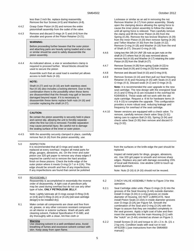
less than 2 inch lbs. replace during reassembly. Remove the four Screws (4-5) and Washers (4-8).
4.4.2 Grasp Outer Piston (4-25) and remove the entire piston/shaft assembly from the outlet of the valve.
4.4.3 Remove and discard O-rings (4-7) and (4-6) from the shoulder and groove of the Piston Retainer (3-21).
WARNING:
Before proceeding further beware that the outer piston and attaching parts are heavily spring loaded and a vise or similar should be used to safely disassemble the piston assembly.
4.4.4 As indicated above, a vise or woodworkers clamp is required to proceed further. Wood blocks should be used to secure the piston
Assemble such that an axial load is exerted yet allows access to both Nuts (4-16).
NOTE:
Shaft (4-27) and nut (4-16) are both stainless steel. Nut (4-16) also includes a locking element. Due to this combination there is the possibility when these items are disassembled that the threads may gall or become damaged beyond repair. If it is necessary to disassemble these items replace both nuts (4-16) and consider replacing the shaft (4-27).
CAUTION:
Be certain the piston assembly is securely held in place and cannot slip, allowing the unit to forcibly separate when the first nut (16) is removed. Forcible separation may cause personal injury. Be careful not to damage the sealing surface of the inner or outer piston.
4.4.5 With the assembly securely clamped in place, carefully remove Nut (4-16) from the piston assembly, use
Lockease or similar as an aid in removing the nut. Remove Washer (4-17) from piston assembly. Slowly open the clamping device allowing the spring force to cause the inner piston assembly to follow the clamp until all spring force is relieved. Then carefully remove the clamp and lift the Inner Piston (4-20) from the Spring (4-26). Remove the two bronze Washers (4-29) from the Inner Piston (4-20) then remove Spring (4-26) and Teflon Washer (4-30) from the Guide (4-22). Remove O-ring (4-18) and Washer (4-19) from the end of Shaft (4-27). Discard O-ring (4-18).
4.4.6 Using two thin 3/8-24 UNF-2B nuts as jam nuts on the shaft (4-27) where Nut (4-16) was removed above, remove Nut (4-16) and Washer (4-17) retaining the outer Piston (4-25) from the Shaft (4-27).
4.4.7 Remove Screws (4-28) from spring Guide (4-22) to remove Seal (4-24) and O-ring (4-23) from retainer.
4.4.8 Remove and discard Seal (4-10) and O-ring (4-9).
4.4.9 Remove Screws (4-14) and then pull out Seal Housing Retainer (4-4) and Housing (4-15) with Seals (4-2) and O-rings (4-3). Discard seals (4-2) and O-rings (4-3).
Note: It is recommended the user upgrade to the new seal cartridge. The new design with the energized Seal (4-2) and O-Ring (4-3) are included in the overhaul kit KD64500-6. These seals will not work with the old-style cartridge. Request a -8 kit for hardware items (4-4 & 4-15) to complete the upgrade. This configuration provides a more robust seal, reducing leakage and frequency for overhaul of the seal cartridge.
4.4.10 Newer versions are equipped with a check valve. To remove, carefully remove check valve Stop (3-31) taking care to capture Ball (3-33), Spring (3-34) and check valve Seat (3-35) then remove and discard O-ring (3-32).
5.0 INSPECTION It is recommended that all O-rings and seals be replaced at every overhaul. Inspect all metal parts for dings, gouges, abrasions, etc. On the inner and outer piston use 320 grit paper to remove any sharp edges if required be careful not to remove the hard anodize finish on these pistons. Check the knife-edge of the outer piston where it meets O-ring (3-7 or 4-12A). This edge should be smooth and free of any imperfections. If any imperfections are found that cannot be polished
from the surfaces or the knife-edge the part should be replaced.
Inspect all metal parts for dings, gouges, abrasions, etc. Use 320 grit paper to smooth and remove sharp edges. Replace any part with damage exceeding 15% of local wall thickness. Use alodine 1200 to touch up bared aluminum.
Note: Nuts (3-16) & (4-16) should not be reused.
6.0 REASSEMBLY
Reassembly is accomplished in essentially the reverse order of disassembly. A light coat of petroleum jelly may be used during overhaul but do not use any other type of lube, ONLY PETROLEUM JELLY.
Note: Lightly lubricate all O-rings except O-Ring (3-8) or (4-8) and O-Ring (3-2A) or (4-2A) [old seal cartridge design] to be installed dry).
6.1 Make certain all components are clean and free from oil, grease, or any other corrosion resistant compound on all interior or exterior surfaces. Wash all parts with cleaning solvent, Federal Specification P-D-680, and dry thoroughly with a clean, lint-free cloth or
Warning Use cleaning solvent in a well-ventilated area. Avoid breathing of fumes and excessive solvent contact with skin. Keep away from open flame.
6.2 3 INCH VALVE ASSEMBLY Refer to Figure 3 for this operation.
6.2.1 Seal Cartridge older units: Place O-rings (3-3) into the grooves of the Seal Housing (3-4A) outside diameter. Install O-rings (3-2A) in o-ring grooves on inside diameter of Housing. DO NOT LUBRICATE. Next install Piston Seals (3-15A) in inside diameter grooves over O-rings (3-2A) per Figure 5A. Smooth the combination of the Seal and O-ring (3-2A) with the finger to assure that they are installed completely in the seal grooves. Apply a light coat of lube and then insert the assembly into the main Housing (3-1) with the “notch” on (3-4A) oriented as shown on Figure 3.
6.2.2 Install Screws (3-14) and torque to 18 ± 2 in.-lb. (21 ± 2 kg-cm). Condition seals with seal run-in tool AF42208-1 [use instructions from the SM64800 manual.]
SM64502 October 2012
6
Note: It is recommended the user upgrade to the new seal cartridge. The new design with the energized Seal (3-2) and O-Ring (3-3) are included in the overhaul kit KD64500-5. These seals will not work with the old-style cartridge. Request a -8 kit for hardware items (3-4 & 3-15) to complete the upgrade. This configuration provides a more robust seal, reducing leakage and frequency for overhaul of the seal cartridge.
6.2.3 Seal Cartridge newer units: O-rings (3-3) should be fitted onto the grooves of Seal Housing (3-15). The lubricated Inner Piston Seals (3-2) should be installed on the inside diameter of the Seal Housing (3-15) per Figure 5B. Now insert the assembly into the main Housing (3-1) with the “notch” on (3-4A) oriented as shown on Figure 3. Be careful not to damage the seals during installation.
6.2.4 Install the Seal Housing Retainer (3-4) into the main Housing (3-1) and install Screws (3-14). Torque Screws (3-4) to 18 ± 2 in.-lb. (21 ± 2 kg-cm). When properly installed, it is not necessary to polish the new type seals.
NOTE:
Shaft (3-27) and nut (3-16) are both stainless steel. Nut (3-16) also includes a locking element. Due to this combination there is the possibility when these items are disassembled that the threads may gall or become damaged beyond repair. If it is necessary to disassemble these items replace both nuts (3-16) and consider replacing the shaft (3-27).
6.3 Assemble Outer Piston (3-25) onto Shaft (3-27) using Washer (3-17) and Nut (3-16). Use two thin nuts 3/8-24 UNF-2B nuts as jam nuts on the opposite end of the Shaft (3-27) and tighten the Nut (3-16) 195 ± 10 in.-lb. (225 ± 12 kg-cm).
6.3.1 Install O-ring (3-24) on Seal (3-23) and install in Retainer (3-21). The leg or hook end of the seal should point toward the Outer Piston (3-25). Press the seal into place very carefully in the retainer. Install Screws (3-28) through spring Guide (3-22) and tighten screws equally.
6.3.2 Apply a light coat of lube to inside ID of Seal (3-23) and slide the Retainer (3-21) onto Shaft (3-27).
6.3.3 Install Teflon Washer (3-30) on the shoulder of the spring Guide (3-22).
6.3.4 Place Washer (3-19) over the end of the Shaft (3-27) and install O-ring (3-18) above the washer.
6.3.5 Install Spring (3-26) onto Guide (3-22). Place the two bronze Washers (3-29) on top of the spring and hold them in place by placing the Inner Piston (3-20) over Spring (3-26). Insert assembly into the clamping device used during disassembly. Compress the assembly and allow access to install the Washer (3-17) and Nut (3-16) on the end of the shaft and tighten to 195 ± 10 in.-lb. (225 ± 12 kg-cm).
6.3.6 Install the O-ring (3-6) into groove in Retainer (3-21). Install O-ring (3-7) over the end of the Retainer (3-21) to where it rests against the retainer’s shoulder.
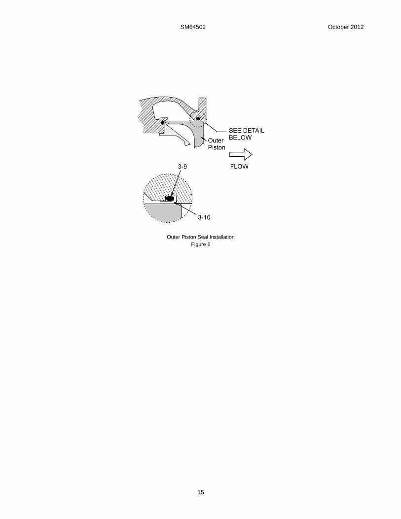
6.3.7 Insert the non-lubricated O-ring (3-9) into the groove in the outlet of Housing (3-1) Install Seal (3-10) over O-ring (3-9) (Refer to Figure 6).
6.3.8 On older versions, if equipped, place O-ring (3-13) over Retainer (3-11) and install the assembly into the main housing fully without cutting the O-ring (3-13). Rotate the retainer to line up the four holes with the mating holes in the housing and install Screws (3-12).
6.3.9 Insert piston assembly into the housing and rotate Outer Piston (3-25) to line up the four holes with the mating holes in the housing. Place O-rings (3-8) over Screws (3-5) and tighten in a cross manner.
6.3.10 On newer units with a check valve install or ensure valve Seat (3-35) is in the cavity in Housing (3-1). Install Spring (3-34) with Ball (3-33) over the spring. Place O-ring (3-32) onto check valve Stop (3-31) and thread into housing until seated.
6.4 4 INCH VALVE ASSEMBLY- Refer to Figure 4 for this operation.
6.4.1 Seal Cartridge older units: Place O-rings (4-3) into the grooves of the Seal Housing (4-4A) outside diameter. Install O-rings (4-2A) in O-ring grooves on inside diameter of Housing. DO NOT LUBRICATE. Next install Piston Seals (4-15A) in inside diameter grooves over O-rings (4-2A) per Figure 5A. Smooth the combination of the Seal and O-ring (4-2A) with the finger to assure that they are installed completely in the seal grooves. Apply a light coat of lube and then insert the assembly into the main Housing (3-1) with the “notch” on (4-4A) oriented as shown on Figure 3.
6.4.2 Install Screws (4-14) and torque to 18 ± 2 in.-lb. (21 ± 2 kg-cm). Condition seals with seal run-in tool AF42208-1 [use instructions from the SM64800 manual.]
Note: It is recommended the user upgrade to the new seal cartridge. The new design with the energized Seal (4-2) and O-Ring (4-3) are included in the overhaul kit KD64500-6. These seals will not work with the old-style cartridge. Request a -8 kit for hardware items (4-4 & 4-15) to complete the upgrade. This configuration provides a more robust seal, reducing leakage and frequency for overhaul of the seal cartridge.
6.4.3 Seal Cartridge newer units: O-rings (4-3) should be fitted onto the grooves of Seal Housing (4-15). The lubricated Inner Piston Seals (4-2) should be installed on the inside diameter of the Seal Housing (4-15) per Figure 5B. Now insert the assembly into the main Housing (4-1) with the “notch” on (4-4A) oriented as shown on Figure 3. Be careful not to damage the seals during installation.
6.4.4 Install the Seal Housing Retainer (4-4) into the main Housing (4-1) and install Screws (4-14). Torque Screws (4-4) to 18 ± 2 in.-lb. (21 ± 2 kg-cm). When properly installed, it is not necessary to polish the new type seals.
NOTE:
Shaft (4-27) and nut (4-16) are both stainless steel. Nut (4-16) also includes a locking element. Due to this combination there is the possibility when these items are disassembled that the threads may gall or become damaged beyond repair. If it is necessary to disassemble these items replace both nuts (4-16) and consider replacing the shaft (4-27).
6.4.5 Assemble Outer Piston (4-25) onto Shaft (4-27) using Washer (4-17) and Nut (4-16). Use two thin nuts 3/8-24 UNF-2B nuts as jam nuts on the opposite end of the Shaft (4-27) and tighten the Nut (4-16) 195 ± 10 in.-lb. (225 ± 12 kg-cm).
6.4.6 Install O-ring (4-24) on Seal (4-23) and install in Retainer (4-21). The leg or hook end of the seal should point toward the Outer Piston (4-25). Press the seal into place very carefully in the retainer. Install Screws (4-28) through spring Guide (4-22) and tighten screws equally.
SM64502 October 2012
7
6.4.7 Apply a light coat of lube to inside ID of Seal (4-23) and slide the Retainer (4-21) onto Shaft (4-27).
6.4.8 Install Teflon Washer (4-30) on the shoulder of the spring Guide (4-22).
6.4.9 Place Washer (4-19) over the end of the Shaft (4-27) and install O-ring (4-18) above the washer.
6.4.10 Install Spring (4-26) onto Guide (4-22). Place the two bronze Washers (4-29) on top of the spring and hold them in place by placing the Inner Piston (4-20) over Spring (4-26). Insert assembly into the clamping device used during disassembly. Compress the assembly and allow access to install the Washer (4-17) and Nut (4-16) on the end of the shaft and tighten to 195 ± 10 in.-lb. (225 ± 12 kg-cm).
6.4.11 Install the O-ring (4-6) into groove in Retainer (3-21). Install O-ring (4-7) over the end of the Retainer (4-21) to where it rests against the retainer’s shoulder.
6.4.12 Insert the non-lubricated O-ring (4-9) into the groove in the outlet of Housing (4-1) Install Seal (4-10) over O-ring (4-9) (Refer to Figure 6).
6.4.13 Insert piston assembly into the housing and rotate Outer Piston (4-25) to line up the four holes with the mating holes in the housing. Place O-rings (4-8) over Screws (4-5) and tighten in a cross manner.
6.4.14 On newer units with a check valve install or ensure valve Seat (4-35) is in the cavity in Housing (3-1). Install Spring (4-34) with Ball (4-33) over the spring. Place O-ring (3-32) onto check valve Stop (4-31) and thread into housing until seated.
6.5 MANIFOLD ASSEMBLY
6.5.1 Assemble in the reverse order.
6.5.2 If the Plug (2-19) was removed from the manifold then install it in the port marked “To Flow Control”.
6.5.3 Place O-ring (2-7) over Screw (2-8) and install in the opening below the port for the relief valve.
6.5.4 If the Relief Valve (2-9) was removed then install a new one. After the Relief Valve has been adjusted, during flow testing, safety wire the valve to the Screw (2-16) to prevent tampering.
6.5.5 If the Solenoid Valve (2-18) was removed during disassembly, first, secure the O-rings (2-18) to the bottom of the Solenoid Valve (2-18) by applying a small amount of petroleum jelly to the bottom of the valve to help hold the three interface o-rings in place, then install on the Manifold (2-1) using the solenoid mounting screws. Mount the connector onto the solenoid and secure in place by use of the connector retaining screw.
6.5.6 If either Orifice Screw (2-10) or (2-17) were removed reinstall them at this time. Each screw must be installed in its correct location for proper functioning of the valve to occur.
6.5.7 If either bleed valve was disassembled begin by placing O-ring (2-12C) over the Poppet (12B). Lay Plug (2-12A) upside down and insert assembled (2-12B) [Reference Figure 2]. Place Spring (2-12D) over the shaft of Poppet (2-12B). Place the Washer (2-12E) on the Spring (2-12D). Compress assembled unit thus far and use snap or lock ring pliers to separate the Retainer (2-12F) and install in the retainer groove on the inside diameter of the bleeder Plug (2-12A).
6.5.8 Use a product similar to Vibra Seal (2-11) on the pipe threads on item(s) (2-12A) and install Bleeder Assembly (2-12) in bleeder port(s) of manifold.
NOTE:
Do not use Teflon tape on any threads in this product. Loose pieces of tape can cause failure of the product.
6.5.9 If check valve was disassembled begin by placing Spring (2-2) into the cavity marked “fuel”. Next, place O-ring (2-5) over the top of the Check Valve (2-3) and place over the spring. Install Gasket (2-4) onto the Check Valve Housing (2-6) and install in the fuel port of the manifold.
6.4.5 Be careful to install Retainers (2-13) and O-rings (2-14) in the proper places. One may use a coating of petroleum jelly to hold them in place while assembling the manifold to the main valve.
6.4.6 Place the manifold assembly onto the valve and retain with Screw (2-15) tightening to hold securely in place.
7.0 TEST
7.1 The following test procedures will be accomplished after overhaul:
7.2 TEST CONDITIONS
Test media shall be JP-8 MIL-T-83133, Jet A, an odorless kerosene or Stoddard type solvent MIL-PRF-7024E Type II.
BLEEDING VALVE!
Before testing or use, the valve must be bled of all trapped air. After pressurizing the unit, use a plastic rod to depress Poppet 2-12B) with a rag around the unit to absorb fuel flow from the bleeder. This should be done long enough to assure all trapped air is exhausted from the valve.
7.3 VALVE BODY AIR-TIGHTNESS TEST
Note that the various ports noted below are identified by engraved markings, “TO PUMP INLET”, “FUEL”, VENTURI PRESSURE ADJ and “BLEED”. The TO FLOW CONTROL port is not used currently.
7.3.1 Adjust the venturi pressure adjustment regulator such that it is fully closed.
7.3.2 Apply 40-psi air pressure to the fuel sensing port while positioning the unit such that the outlet faces upward. Fill the valve outlet with test fluid and maintain air pressure for one minute. Visually check for air leakage into the fuel path by observing air bubble formation. There shall be no leakage that exceeds 1 cc/minute.
7.3.3 Connect a 0-300-psig test fluid source to the valve inlet and outlet. Connect the valve outlet to a fitting equipped with a shutoff valve.
7.3.4 Energize the solenoid valve. Slowly increase fuel pressure to the valve inlet to open the piston. Fill the valve from the inlet with test fluid while bleeding all air from the valve through the outlet valve. Keep the valve outlet at the highest point while bleeding. De-energize the solenoid valve.
7.3.5 When the test setup is full and bled, pressurize the valve inlet and outlet simultaneously with the test fluid pressure at 125-psi and maintain for one minute while visually inspecting the valve for indication of external leakage. There shall be none.
7.3.6 Reduce the test pressure to 4-6-psig and maintain for one minute while visually inspecting for external leakage. There shall be none.
SM64502 October 2012
8
7.3.7 Energize the solenoid valve and pressurize the valve at inlet and outlet simultaneously with test fluid pressure at 125-psi and maintain for one minute while observing for leakage. There should be not evidence of external leakage.
7.3.8 Release internal pressure and drain the test fluid.
7.4 FUNCTIONAL TEST
Functional testing can be accomplished on the vehicle unless there is a complete test rig available. If there is contact Carter for more details on how to test for full function. Adjustment of the pressure at the Venturi is accomplished by using the integral regulator on the side of the manifold. After adjustment is completed, lockwire it to the provided screw to prevent tampering.
8.0 ILLUSTRATED PARTS CATALOG
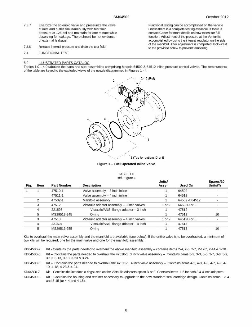
Tables 1.0 – 4.0 tabulate the parts and sub-assemblies comprising Models 64502 & 64512 inline pressure control valves. The item numbers of the table are keyed to the exploded views of the nozzle diagrammed in Figures 1 - 4.
Figure 1 – Fuel Operated Inline Valve
TABLE 1.0 Ref. Figure 1
Fig. Item Part Number Description Units/ Assy Used On
Spares/10 Units/Yr
1 1 47510-1 Valve assembly – 3 inch inline 1 64502 -
47511-1 Valve assembly – 4 inch inline 1 64512 -
2 47502-1 Manifold assembly 1 64502 & 64512 -
3 47512 Victaulic adapter assembly – 3 inch valves 1 or 2 64502D or E -
4 221596 Victaulic/ANSI flange adapter – 3 inch 1 47512 -
5 MS29513-245 O-ring 1 47512 10
3 47513 Victaulic adapter assembly – 4 inch valves 1 or 2 64512D or E -
4 221597 Victaulic/ANSI flange adapter – 4 inch 1 47513 -
5 MS29513-255 O-ring 1 47513 10
Kits to overhaul the main valve assembly and the manifold are available (see below). If the entire valve is to be overhauled, a minimum of two kits will be required, one for the main valve and one for the manifold assembly.
KD64500-2 Kit - Contains the parts needed to overhaul the above manifold assembly – contains items 2-4, 2-5, 2-7, 2-12C, 2-14 & 2-20.
KD64500-5 Kit – Contains the parts needed to overhaul the 47510-1 3 inch valve assembly – Contains items 3-2, 3-3, 3-6, 3-7, 3-8, 3-9, 3-10, 3-13, 3-18, 3-23 & 3-24.
KD64500-6 Kit – Contains the parts needed to overhaul the 47511-1 4 inch valve assembly – Contains items 4-2, 4-3, 4-6, 4-7, 4-9, 4-10, 4-18, 4-23 & 4-24.
KD64500-7 Kit – Contains the interface o-rings used on the Victaulic Adapters option D or E. Contains items- 1-5 for both 3 & 4 inch adapters.
KD64500-8 Kit – Contains the housing and retainer necessary to upgrade to the now standard seal cartridge design. Contains items – 3-4 and 3-15 (or 4-4 and 4-15).
SM64502 October 2012
9
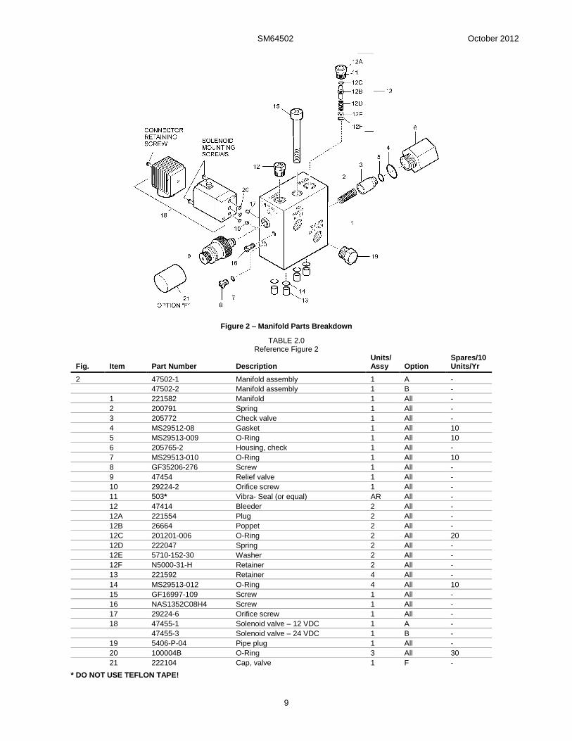
Figure 2 – Manifold Parts Breakdown
TABLE 2.0 Reference Figure 2
Fig. Item Part Number Description Units/ Assy Option
Spares/10 Units/Yr
2 47502-1 Manifold assembly 1 A -
47502-2 Manifold assembly 1 B -
1 221582 Manifold 1 All -
2 200791 Spring 1 All -
3 205772 Check valve 1 All -
4 MS29512-08 Gasket 1 All 10
5 MS29513-009 O-Ring 1 All 10
6 205765-2 Housing, check 1 All -
7 MS29513-010 O-Ring 1 All 10
8 GF35206-276 Screw 1 All -
9 47454 Relief valve 1 All -
10 29224-2 Orifice screw 1 All -
11 503* Vibra- Seal (or equal) AR All -
12 47414 Bleeder 2 All -
12A 221554 Plug 2 All -
12B 26664 Poppet 2 All -
12C 201201-006 O-Ring 2 All 20
12D 222047 Spring 2 All -
12E 5710-152-30 Washer 2 All -
12F N5000-31-H Retainer 2 All -
13 221592 Retainer 4 All -
14 MS29513-012 O-Ring 4 All 10
15 GF16997-109 Screw 1 All -
16 NAS1352C08H4 Screw 1 All -
17 29224-6 Orifice screw 1 All -
18 47455-1 Solenoid valve – 12 VDC 1 A -
47455-3 Solenoid valve – 24 VDC 1 B -
19 5406-P-04 Pipe plug 1 All -
20 100004B O-Ring 3 All 30
21 222104 Cap, valve 1 F -
* DO NOT USE TEFLON TAPE!
SM64502 October 2012
10
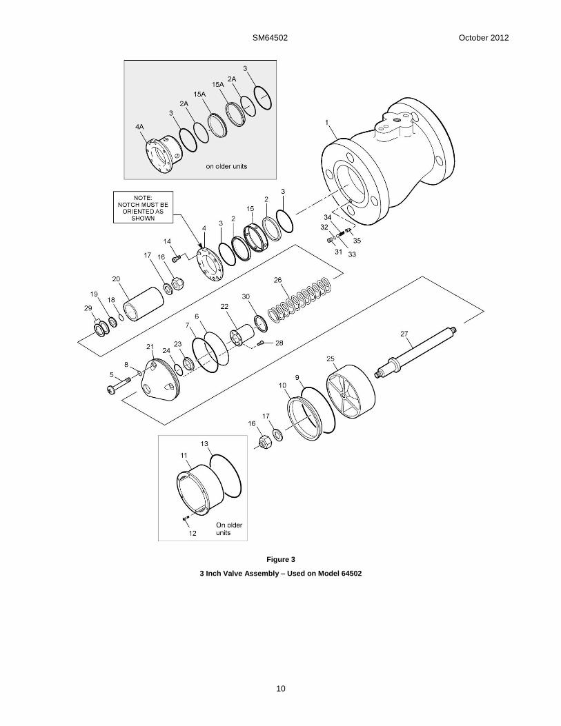
Figure 3
3 Inch Valve Assembly – Used on Model 64502

SM64502 October 2012
11
TABLE 3.0
3” Valve Assembly
Used on 64502 Reference Figure 3
Fig. Item Part Number Description Units/ Assy
Spares/10 Units/Yr
3 47510-1 Valve assembly, 3 inch 1 1
1 47506 Valve housing 1 -
2 222165 Seal, inner piston 2 10
2A MS29513-129 O-Ring 2 10
3 MS29513-134 O-Ring 2 10
4 222161 Retainer, seal housing 1 -
4A 221307 Seal housing 1 -
5 220685-1250 Screw 4 -
6 MS29513-038 O-Ring 1 10
7 201201-231 O-Ring 1 10
8 MS29513-008 O-Ring 4 10
9 MS29513-151 O-Ring 1 10
10 220665 Seal, outer piston 1 10
11 221193 Seal housing 1 -
12 GF16997-18 Screw 6 -
13 MS29513-042 O-Ring 1 10
14 GF16997-32L Screw 4 -
15 222160 Housing, seal 1 -
15A 200758 Seal, inner piston 2 10
16-30 47508-1 Piston assembly, 3 inch 1 1
16 38NST188 Nut self-locking 2 20
17 GF960C616L Flat washer 2 -
18 MS29513-012 O-Ring 1 10
19 202291 Washer 1 -
20 200759 Inner piston 1 -
21 221607 Seal retainer 1 -
22 221594 Guide 1 -
23 221595 Seal, piston shaft 1 10
24 203565 O-Ring 1 10
25 220666 Outer piston 1 -
26 220005 Spring 1 -
27 202290 Shaft 1 -
28 NAS1351C04-4 Screw 6 -
29 5720-158-25 Washer, bronze 2 -
30 5610-381-50 Washer, Teflon 1 -
31 222017 Seat, check valve 1 -
32 MS29513-007 O-Ring 1 10
33 220417 Ball 1 -
34 C0180-012-0620S Spring 1 -
35 222019 Stop, check valve 1 -
SM64502 October 2012
12
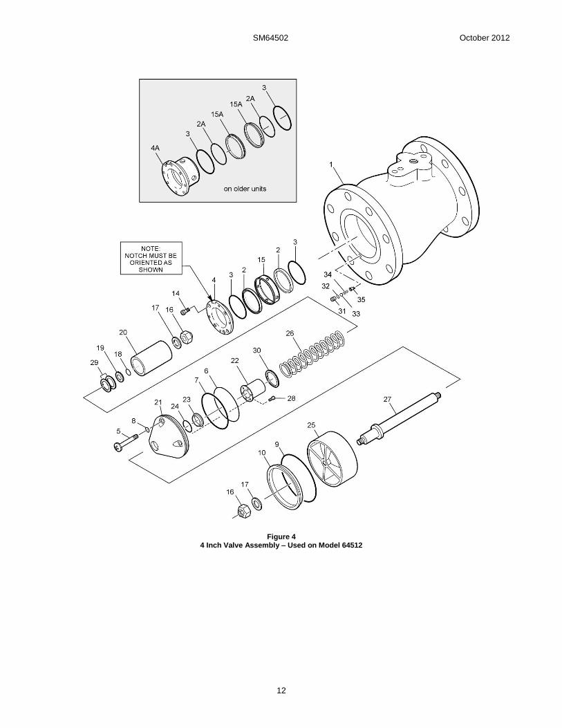
Figure 4 4 Inch Valve Assembly – Used on Model 64512
SM64502 October 2012
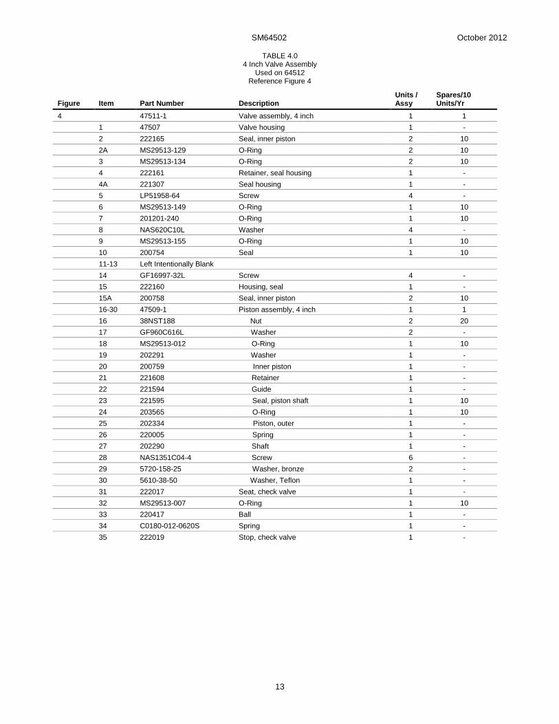
13
TABLE 4.0 4 Inch Valve Assembly
Used on 64512 Reference Figure 4
Figure Item Part Number Description Units / Assy
Spares/10 Units/Yr
4 47511-1 Valve assembly, 4 inch 1 1
1 47507 Valve housing 1 -
2 222165 Seal, inner piston 2 10
2A MS29513-129 O-Ring 2 10
3 MS29513-134 O-Ring 2 10
4 222161 Retainer, seal housing 1 -
4A 221307 Seal housing 1 -
5 LP51958-64 Screw 4 -
6 MS29513-149 O-Ring 1 10
7 201201-240 O-Ring 1 10
8 NAS620C10L Washer 4 -
9 MS29513-155 O-Ring 1 10
10 200754 Seal 1 10
11-13 Left Intentionally Blank
14 GF16997-32L Screw 4 -
15 222160 Housing, seal 1 -
15A 200758 Seal, inner piston 2 10
16-30 47509-1 Piston assembly, 4 inch 1 1
16 38NST188 Nut 2 20
17 GF960C616L Washer 2 -
18 MS29513-012 O-Ring 1 10
19 202291 Washer 1 -
20 200759 Inner piston 1 -
21 221608 Retainer 1 -
22 221594 Guide 1 -
23 221595 Seal, piston shaft 1 10
24 203565 O-Ring 1 10
25 202334 Piston, outer 1 -
26 220005 Spring 1 -
27 202290 Shaft 1 -
28 NAS1351C04-4 Screw 6 -
29 5720-158-25 Washer, bronze 2 -
30 5610-38-50 Washer, Teflon 1 -
31 222017 Seat, check valve 1 -
32 MS29513-007 O-Ring 1 10
33 220417 Ball 1 -
34 C0180-012-0620S Spring 1 -
35 222019 Stop, check valve 1 -

SM64502 October 2012
14
Table 5.0
Torque Specifications 64500
Fig. Item Part Number Description Torque in.-lb.
3 or 4 14 GF16997-32L Screw(s) 18 ± 2 in.-lb. (21 ± 2 kg-cm)
3 or 4 16 38NST188 Nut(s) 195 ± 10 in.-lb. (225 ± 12 kg-cm)
Inner Piston Seal Installation (Older units) FIGURE 5A
Inner Piston Seal Installation (Newer units)
Figure 5B
SM64502 October 2012
15
Outer Piston Seal Installation
Figure 6
Aerospace Group Conveyance Systems Division 9650 Jeronimo Road Irvine, CA 92618 Ph (949) 452-9500 Fax (949) 452-9992