fs5a shop manual
DESCRIPTION
Mazda Transmission Shop ManualTRANSCRIPT

Title SectionFEATURES SERVICE
GENERAL INFORMATION 00 00
TRANSMISSION/TRANSAXLE 05 05
CONTENTSAutomaticTransaxleWorkshopManualFS5A–EL
FOREWORD
This manual explains the service points for the above-indicated automotive system.This manual covers all models with the above-indicated automotive system, not any one specific model.In order to do these procedures safely, quickly, and correctly, you must first read this manual and any other relevant service materials carefully.All the contents of this manual, including drawings and specifications, are the latest available at the time of printing.As modifications affecting repair or maintenance occur, relevant information supplementary to this volume will be made available at Mazda dealers.This manual should be kept up-to-date.Mazda Motor Corporation reserves the right to alter the specifications and contents of this manual without obligation or advance notice.All rights reserved.No part of this book may be reproduced or used in any form or by any means, electronic or mechanical-including photocopying and recording and the use of any kind of information storage and retrieval system-without permission in writing.
Mazda Motor CorporationHIROSHIMA, JAPAN
© 2005 Mazda Motor CorporationPRINTED IN U.S.A., JUNE 2005Form No. 1859–1U–05FPart No. 9999–95–FS5A–06

FEATURES

05–17–1
05TRANSMISSION/TRANSAXLESECTION
05–17
Toc of SCTAUTOMATIC TRANSAXLE. . . .05-17
Toc of SCT
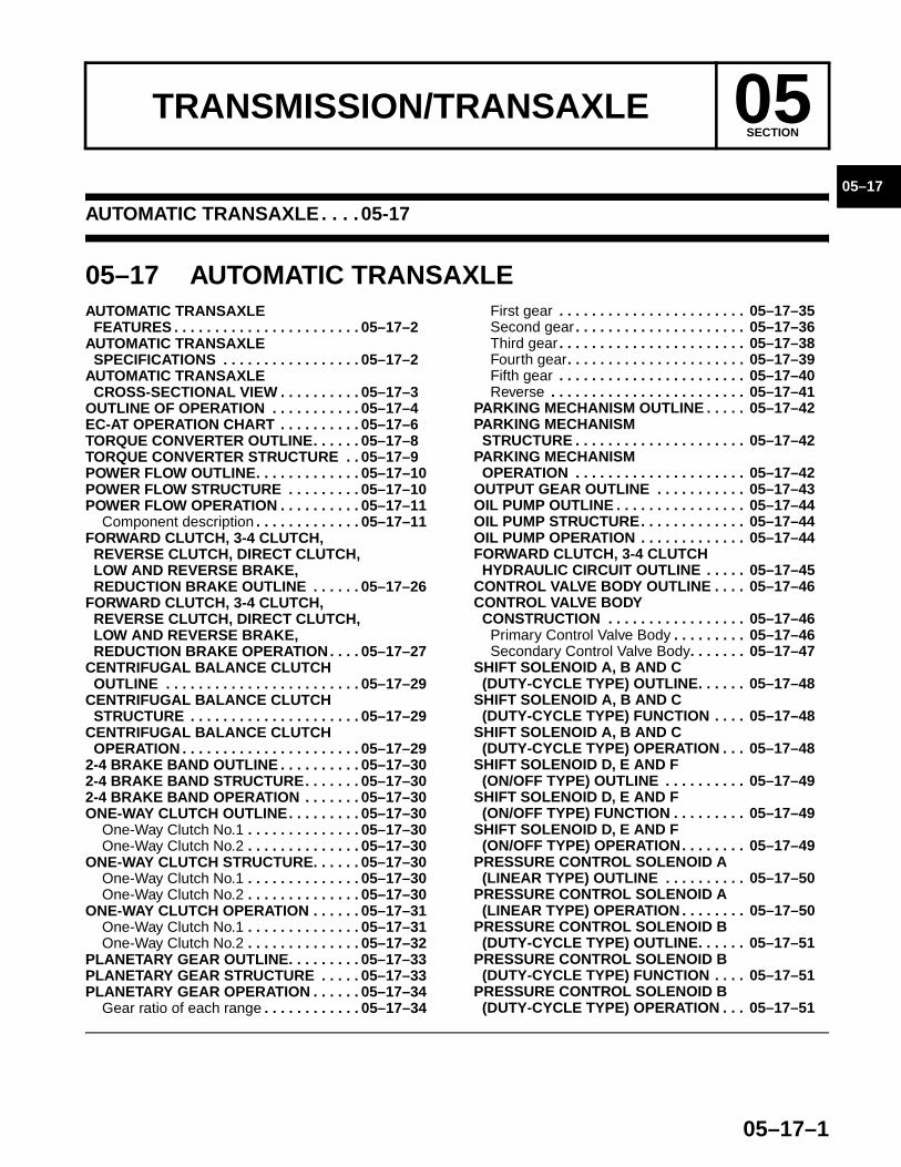
05–17 AUTOMATIC TRANSAXLEAUTOMATIC TRANSAXLE
FEATURES . . . . . . . . . . . . . . . . . . . . . . . 05–17–2AUTOMATIC TRANSAXLE
SPECIFICATIONS . . . . . . . . . . . . . . . . . 05–17–2AUTOMATIC TRANSAXLE
CROSS-SECTIONAL VIEW . . . . . . . . . . 05–17–3OUTLINE OF OPERATION . . . . . . . . . . . 05–17–4EC-AT OPERATION CHART . . . . . . . . . . 05–17–6TORQUE CONVERTER OUTLINE. . . . . . 05–17–8TORQUE CONVERTER STRUCTURE . . 05–17–9POWER FLOW OUTLINE. . . . . . . . . . . . . 05–17–10POWER FLOW STRUCTURE . . . . . . . . . 05–17–10POWER FLOW OPERATION . . . . . . . . . . 05–17–11
Component description . . . . . . . . . . . . . 05–17–11FORWARD CLUTCH, 3-4 CLUTCH,
REVERSE CLUTCH, DIRECT CLUTCH, LOW AND REVERSE BRAKE, REDUCTION BRAKE OUTLINE . . . . . . 05–17–26
FORWARD CLUTCH, 3-4 CLUTCH, REVERSE CLUTCH, DIRECT CLUTCH,LOW AND REVERSE BRAKE, REDUCTION BRAKE OPERATION. . . . 05–17–27
CENTRIFUGAL BALANCE CLUTCH OUTLINE . . . . . . . . . . . . . . . . . . . . . . . . 05–17–29
CENTRIFUGAL BALANCE CLUTCH STRUCTURE . . . . . . . . . . . . . . . . . . . . . 05–17–29
CENTRIFUGAL BALANCE CLUTCH OPERATION . . . . . . . . . . . . . . . . . . . . . . 05–17–29
2-4 BRAKE BAND OUTLINE . . . . . . . . . . 05–17–302-4 BRAKE BAND STRUCTURE. . . . . . . 05–17–302-4 BRAKE BAND OPERATION . . . . . . . 05–17–30ONE-WAY CLUTCH OUTLINE. . . . . . . . . 05–17–30
One-Way Clutch No.1 . . . . . . . . . . . . . . 05–17–30One-Way Clutch No.2 . . . . . . . . . . . . . . 05–17–30
ONE-WAY CLUTCH STRUCTURE. . . . . . 05–17–30One-Way Clutch No.1 . . . . . . . . . . . . . . 05–17–30One-Way Clutch No.2 . . . . . . . . . . . . . . 05–17–30
ONE-WAY CLUTCH OPERATION . . . . . . 05–17–31One-Way Clutch No.1 . . . . . . . . . . . . . . 05–17–31One-Way Clutch No.2 . . . . . . . . . . . . . . 05–17–32
PLANETARY GEAR OUTLINE. . . . . . . . . 05–17–33PLANETARY GEAR STRUCTURE . . . . . 05–17–33PLANETARY GEAR OPERATION . . . . . . 05–17–34
Gear ratio of each range . . . . . . . . . . . . 05–17–34
First gear . . . . . . . . . . . . . . . . . . . . . . . 05–17–35Second gear . . . . . . . . . . . . . . . . . . . . . 05–17–36Third gear . . . . . . . . . . . . . . . . . . . . . . . 05–17–38Fourth gear. . . . . . . . . . . . . . . . . . . . . . 05–17–39Fifth gear . . . . . . . . . . . . . . . . . . . . . . . 05–17–40Reverse . . . . . . . . . . . . . . . . . . . . . . . . 05–17–41
PARKING MECHANISM OUTLINE . . . . . 05–17–42PARKING MECHANISM
STRUCTURE . . . . . . . . . . . . . . . . . . . . . 05–17–42PARKING MECHANISM
OPERATION . . . . . . . . . . . . . . . . . . . . . 05–17–42OUTPUT GEAR OUTLINE . . . . . . . . . . . 05–17–43OIL PUMP OUTLINE . . . . . . . . . . . . . . . . 05–17–44OIL PUMP STRUCTURE. . . . . . . . . . . . . 05–17–44OIL PUMP OPERATION . . . . . . . . . . . . . 05–17–44FORWARD CLUTCH, 3-4 CLUTCH
HYDRAULIC CIRCUIT OUTLINE . . . . . 05–17–45CONTROL VALVE BODY OUTLINE . . . . 05–17–46CONTROL VALVE BODY
CONSTRUCTION . . . . . . . . . . . . . . . . . 05–17–46Primary Control Valve Body . . . . . . . . . 05–17–46Secondary Control Valve Body. . . . . . . 05–17–47
SHIFT SOLENOID A, B AND C (DUTY-CYCLE TYPE) OUTLINE. . . . . . 05–17–48
SHIFT SOLENOID A, B AND C(DUTY-CYCLE TYPE) FUNCTION . . . . 05–17–48
SHIFT SOLENOID A, B AND C (DUTY-CYCLE TYPE) OPERATION . . . 05–17–48
SHIFT SOLENOID D, E AND F(ON/OFF TYPE) OUTLINE . . . . . . . . . . 05–17–49
SHIFT SOLENOID D, E AND F (ON/OFF TYPE) FUNCTION . . . . . . . . . 05–17–49
SHIFT SOLENOID D, E AND F(ON/OFF TYPE) OPERATION. . . . . . . . 05–17–49
PRESSURE CONTROL SOLENOID A(LINEAR TYPE) OUTLINE . . . . . . . . . . 05–17–50
PRESSURE CONTROL SOLENOID A(LINEAR TYPE) OPERATION . . . . . . . . 05–17–50
PRESSURE CONTROL SOLENOID B (DUTY-CYCLE TYPE) OUTLINE. . . . . . 05–17–51
PRESSURE CONTROL SOLENOID B (DUTY-CYCLE TYPE) FUNCTION . . . . 05–17–51
PRESSURE CONTROL SOLENOID B (DUTY-CYCLE TYPE) OPERATION . . . 05–17–51
End of Toc
AUTOMATIC TRANSAXLE
05–17–2
AUTOMATIC TRANSAXLE FEATURESE6U051700000A01
End Of SieAUTOMATIC TRANSAXLE SPECIFICATIONS
E6U051700000A02
End Of Sie
Realization of excellent shift quality
• Electronic pressure-adjusting control of line pressure by a liner type solenoid (pressure control solenoid A) adopted
• Electronic control (direct electric shift control) of clutch pressure by duty-cycle type solenoids (shift solenoid A, B, and C, pressure control solenoid B) adopted
Superior shift quality • Centrifugal balance clutch chamber adoptedHigh efficiency, compactness, lightweight • Miniature trochoid gear oil pump with torque converter direct drive adopted
Improved reliability • Variable resistor type TR switch has been adopted
Improved marketability • Sport AT adopted• Sub-shifting mechanism has been adopted
Improved reliability, reduced noise and vibration
• A double arranged gear with a single planetary gear unit is has been adopted as the main shifting mechanism
• A single planetary gear unit is has been adopted as the sub-shifting mechanism
Item SpecificationEngine type L3Automatic transaxle type FS5A-EL
Gear ratio
1GR 3.6202GR 1.9253GR 1.2854GR 0.9395GR 0.692Reverse 3.405
Final gear ratio 3.863
ATFType ATF M-VCapacity (Approx. quantity) (L {US qt, lmp qt}) 8.14 {8.60, 7.16}
Torque converter stall torque ratio 1.84
Hydraulic system(Number of drive/driven gear plates)
Forward clutch 4/43-4 clutch 3/3Reverse clutch 2/2Direct clutch 2/3Low and reverse brake 5/5Reduction brake 3/5
Band servo Servo diameter(Piston outer dia.) (mm {in}) 64.6 {2.54}
Front planetary gear(Number of teeth)
Front sun gear 49Front pinion gear 20Front internal gear 89
Rear planetary gear(Number of teeth)
Rear sun gear 37Rear pinion gear 30Rear internal gear 98
Primary gear (number of teeth) 86Secondary gear (number of teeth) 82
Secondary planetary gear(Number of teeth)
Secondary sun gear 31Secondary pinion gear 29Secondary internal gear 89
Output gear (number of teeth) 22Ring gear (number of teeth) 85
AUTOMATIC TRANSAXLE
05–17–3
05–17
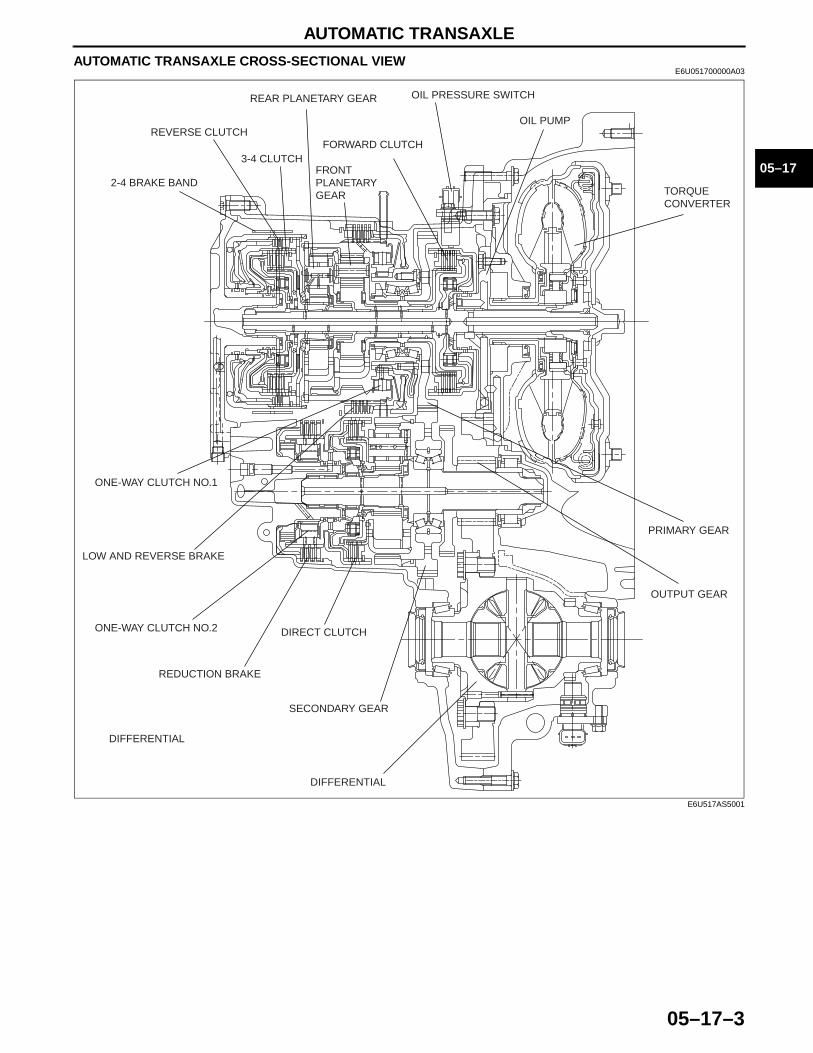
AUTOMATIC TRANSAXLE CROSS-SECTIONAL VIEWE6U051700000A03
End Of Sie
PRIMARY GEAR
OUTPUT GEAR
DIFFERENTIAL
DIFFERENTIAL
SECONDARY GEAR
DIRECT CLUTCH
REDUCTION BRAKE
ONE-WAY CLUTCH NO.2
LOW AND REVERSE BRAKE
ONE-WAY CLUTCH NO.1
2-4 BRAKE BAND
REVERSE CLUTCH
3-4 CLUTCH
REAR PLANETARY GEAR
FRONT PLANETARY GEAR
FORWARD CLUTCH
OIL PRESSURE SWITCH
OIL PUMP
TORQUE CONVERTER
E6U517AS5001
AUTOMATIC TRANSAXLE
05–17–4
OUTLINE OF OPERATIONE6U051700000A04
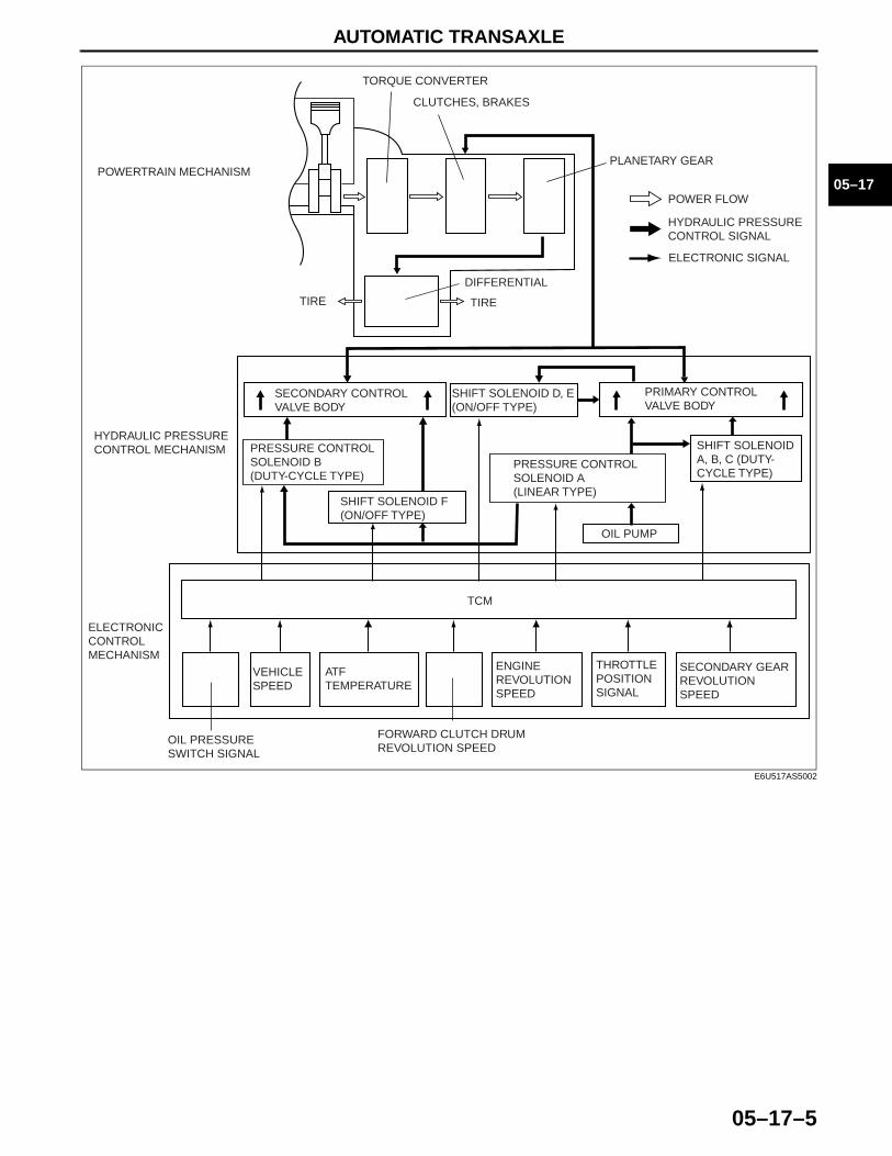
• The operation of the electronic automatic transaxle is classified into three systems: the electronic control mechanism, the hydraulic pressure control mechanism, and the powertrain mechanism (includes the torque converter mechanism). The operation of each system is as follows:— Electronic control mechanism
• According to the signals from the switches and sensors in the input system, the TCM outputs the signal which matches the present driving condition to the linear type solenoid, ON/OFF type solenoids and the duty-cycle type solenoids in the hydraulic pressure control mechanism.
— Hydraulic pressure control mechanism• According to the signals from the TCM, each solenoid operates to switch the hydraulic passages in the
control valve body and controls the clutch engagement pressure.• The line pressure is adjusted by the linear type pressure control solenoid A and duty-cycle type
pressure control solenoid B. The hydraulic passages are switched by the ON/OFF type solenoids (shift solenoid D and E.) And the clutch engagement pressure is controlled by the duty-cycle type solenoids (shift solenoid A, B, and C) and ON/OFF type solenoid (shift solenoid F).
— Powertrain mechanism• The driving force from the engine is transmitted through the torque converter to the transaxle.• Shift solenoid A, B, and C (duty-cycle type), pressure solenoid B (duty-cycle type), shift solenoid F (ON/
OFF type) or clutch engagement pressure control by the control valve enable the transmitted input driving force to be converted to optimum output driving force via the differential.
AUTOMATIC TRANSAXLE
05–17–5
05–17
End Of Sie
TCM
SECONDARY GEAR REVOLUTION SPEED
THROTTLE POSITION SIGNAL
ENGINE REVOLUTION SPEED
FORWARD CLUTCH DRUM REVOLUTION SPEED
ATF TEMPERATURE
VEHICLE SPEED
OIL PRESSURE SWITCH SIGNAL
SHIFT SOLENOID F (ON/OFF TYPE)
PRESSURE CONTROL SOLENOID A(LINEAR TYPE)
PRESSURE CONTROL SOLENOID B(DUTY-CYCLE TYPE)
OIL PUMP
ELECTRONIC SIGNAL
HYDRAULIC PRESSURE CONTROL SIGNAL
POWER FLOW
SHIFT SOLENOID A, B, C (DUTY-CYCLE TYPE)
SECONDARY CONTROL VALVE BODY
SHIFT SOLENOID D, E (ON/OFF TYPE)
PRIMARY CONTROL VALVE BODY
TIRETIRE
DIFFERENTIAL
PLANETARY GEAR
CLUTCHES, BRAKES
TORQUE CONVERTER
ELECTRONIC CONTROL MECHANISM
HYDRAULIC PRESSURE CONTROL MECHANISM
POWERTRAIN MECHANISM
E6U517AS5002
AUTOMATIC TRANSAXLE
05–17–6
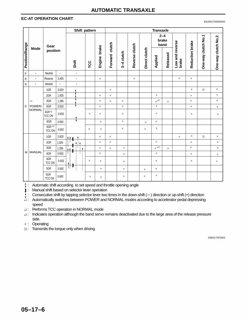
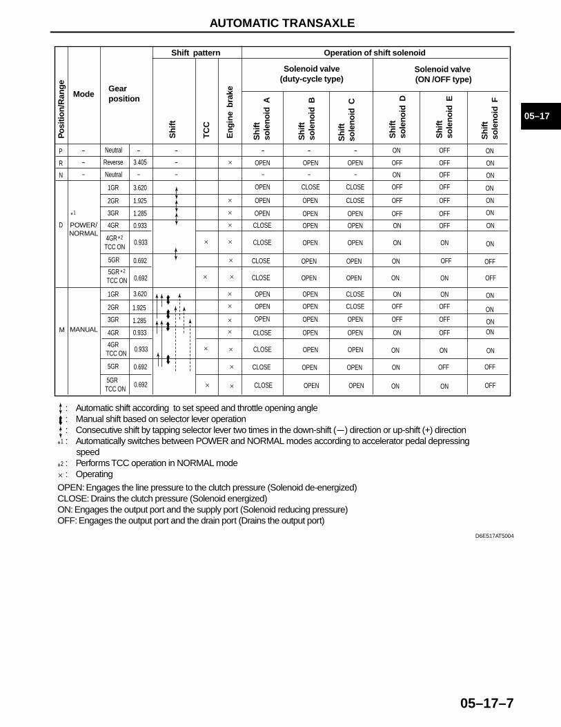
EC-AT OPERATION CHARTE6U051700000A05
1*
2*3*
: Automatic shift according to set speed and throttle opening angle: Manual shift based on selector lever operation: Consecutive shift by tapping selector lever two times in the down-shift ( ) direction or up-shift (+) direction: Automatically switches between POWER and NORMAL modes according to accelerator pedal depressing speed: Performs TCC operation in NORMAL mode: Indicates operation although the band servo remains deactivated due to the large area of the release pressure side.: Operating: Transmits the torque only when driving
Mode
Neutral
Neutral
3.405
3.620
1.925
1.285
0.933
0.692
1GR
2GR
3GR
4GR
Reverse
Gear position
Shift pattern Transaxle
2-4brakeband
Po
sitio
n/R
ang
e
Sh
ift
TC
C
En
gin
e b
rake
Rev
erse
clu
tch
On
e-w
ay c
lutc
h N
o.1
Low
an
d r
ever
seb
rake
3 -4
clu
tch
Ap
plie
d
Rel
ease
d
Fo
rwar
d c
lutc
h
P
R
N
-
-
-
-
-
-
-
-
D
1*
2*
3*
3*M
POWER/NORMAL
4GR TCC ON
1GR
2GR
3GR
4GRMANUAL
5GR TCC ON
5GR
4GR TCC ON
5GR TCC ON
5GR
0.933
0.692
3.620
1.925
1.285
0.933
0.933
0.692
0.692
On
e-w
ay c
lutc
h N
o.2
Red
uct
ion
bra
ke
Dir
ect c
lutc
h
2*
D6E517AT5003
AUTOMATIC TRANSAXLE
05–17–7
05–17
End Of Sie
1*
2*
OPEN: Engages the line pressure to the clutch pressure (Solenoid de-energized)CLOSE: Drains the clutch pressure (Solenoid energized)ON: Engages the output port and the supply port (Solenoid reducing pressure)OFF: Engages the output port and the drain port (Drains the output port)
: Automatic shift according to set speed and throttle opening angle: Manual shift based on selector lever operation: Consecutive shift by tapping selector lever two times in the down-shift ( ) direction or up-shift (+) direction: Automatically switches between POWER and NORMAL modes according to accelerator pedal depressing speed: Performs TCC operation in NORMAL mode: Operating
Mode
Neutral
Neutral
3.405
3.620
1.925
1.285
0.933
0.692
1GR
2GR
3GR
4GR
Reverse
Gear position
Shift pattern Operation of shift solenoid
Solenoid valve(duty-cycle type)
Solenoid valve (ON /OFF type)
Po
sitio
n/R
ang
e
Sh
ift
TC
C
En
gin
e b
rake
Sh
iftso
len
oid
D
Sh
iftso
len
oid
E
P
R
N
-
-
-
-
-
-
-
-
OPEN
-
-
OPEN
-
-
OPEN OFF OFF
OPEN CLOSE CLOSE OFF OFF
OPEN OPEN CLOSE
OPEN OPEN CLOSE
OPEN OPEN CLOSE
OFF OFF
OPEN OPEN OPEN OFF OFF
OPEN OPEN OPEN OFF OFF
OPEN OPEN ON OFF
OFF OFF
CLOSE OPEN OPEN ON OFF
CLOSE
CLOSE
OPEN OPEN ON ON
ON ON
ON OFF
ON OFF
-
-
D
1*
2*
M
POWER/NORMAL
4GR TCC ON
1GR
2GR
3GR
4GRMANUAL
Sh
iftso
len
oid
F
OFF
OFF
ON
ON
5GR TCC ON
5GR
4GR TCC ON
5GR TCC ON
5GR
0.933
0.692
3.620
1.925
1.285
0.933
0.933
0.692
0.692
ON ON
ON ON
ON ON
OFF
ON
ON
ON
ON
ON
ON
ON
ON
ONON
ON
OFF
CLOSE OPEN OPEN ON
CLOSE OPEN OPEN
ONCLOSE OPEN OPEN
CLOSE OPEN OPEN
CLOSE OPEN OPEN
Sh
iftso
len
oid
A
Sh
iftso
len
oid
B
Sh
iftso
len
oid
C
OFF
OFF
2*
D6E517AT5004
AUTOMATIC TRANSAXLE
05–17–8
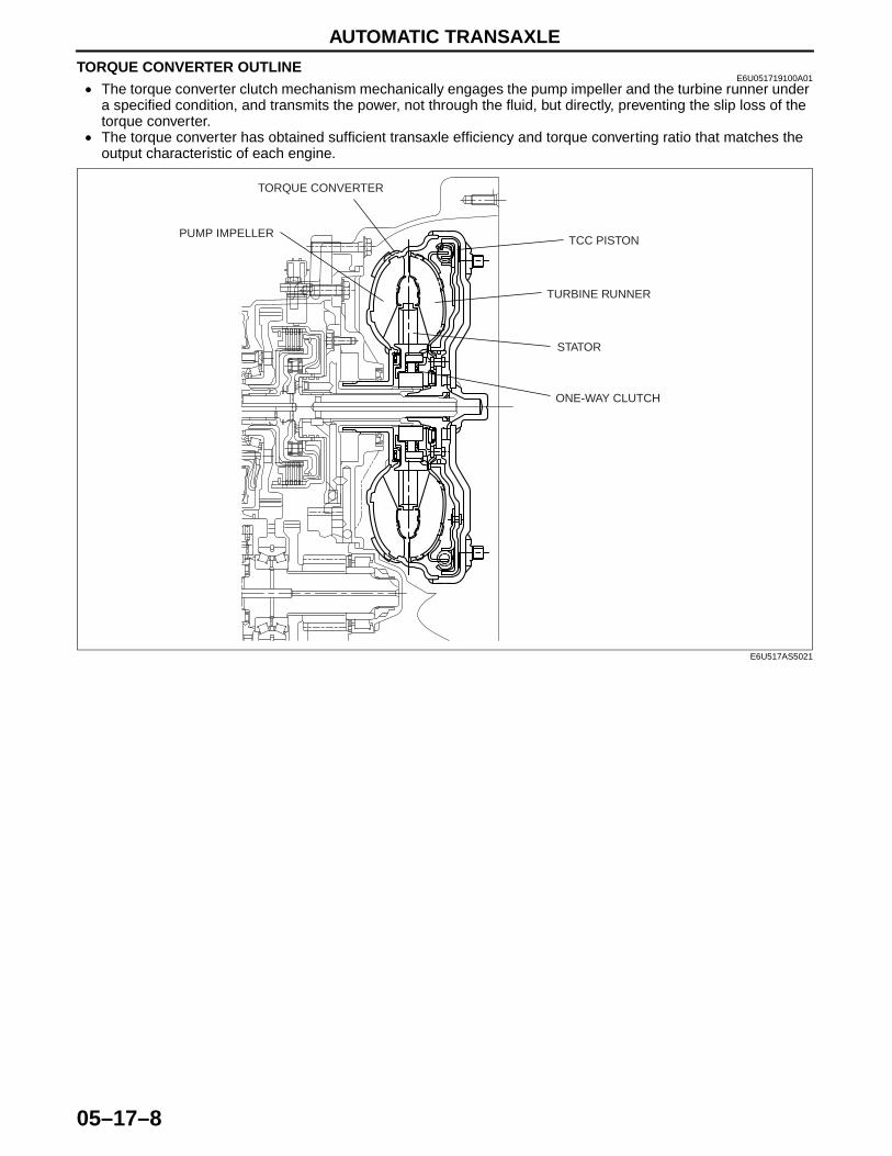
TORQUE CONVERTER OUTLINEE6U051719100A01
• The torque converter clutch mechanism mechanically engages the pump impeller and the turbine runner under a specified condition, and transmits the power, not through the fluid, but directly, preventing the slip loss of the torque converter.
• The torque converter has obtained sufficient transaxle efficiency and torque converting ratio that matches the output characteristic of each engine.
End Of Sie
ONE-WAY CLUTCH
STATOR
TURBINE RUNNER
TCC PISTONPUMP IMPELLER
TORQUE CONVERTER
E6U517AS5021
AUTOMATIC TRANSAXLE
05–17–9
05–17
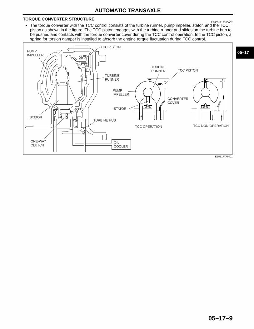
TORQUE CONVERTER STRUCTUREE6U051719100A02
• The torque converter with the TCC control consists of the turbine runner, pump impeller, stator, and the TCC piston as shown in the figure. The TCC piston engages with the turbine runner and slides on the turbine hub to be pushed and contacts with the torque converter cover during the TCC control operation. In the TCC piston, a spring for torsion damper is installed to absorb the engine torque fluctuation during TCC control.
End Of Sie
TCC PISTONPUMP IMPELLER
TURBINE RUNNER
STATORTURBINE HUB
ONE-WAY CLUTCH
OIL COOLER
CONVERTER COVER
TCC OPERATION TCC NON-OPERATION
PUMP IMPELLER
TURBINE RUNNER TCC PISTON
STATOR
E6U517YA6001
AUTOMATIC TRANSAXLE
05–17–10
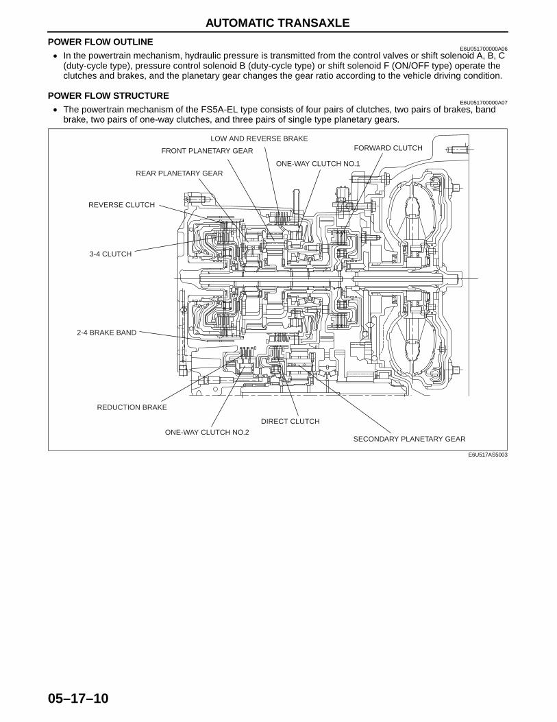
POWER FLOW OUTLINEE6U051700000A06
• In the powertrain mechanism, hydraulic pressure is transmitted from the control valves or shift solenoid A, B, C (duty-cycle type), pressure control solenoid B (duty-cycle type) or shift solenoid F (ON/OFF type) operate the clutches and brakes, and the planetary gear changes the gear ratio according to the vehicle driving condition.
End Of SiePOWER FLOW STRUCTURE
E6U051700000A07• The powertrain mechanism of the FS5A-EL type consists of four pairs of clutches, two pairs of brakes, band
brake, two pairs of one-way clutches, and three pairs of single type planetary gears.
SECONDARY PLANETARY GEAR
DIRECT CLUTCH
ONE-WAY CLUTCH NO.2
REDUCTION BRAKE
2-4 BRAKE BAND
3-4 CLUTCH
REVERSE CLUTCH
REAR PLANETARY GEAR
FRONT PLANETARY GEAR
LOW AND REVERSE BRAKE
ONE-WAY CLUTCH NO.1
FORWARD CLUTCH
E6U517AS5003
AUTOMATIC TRANSAXLE
05–17–11
05–17
End Of SiePOWER FLOW OPERATION
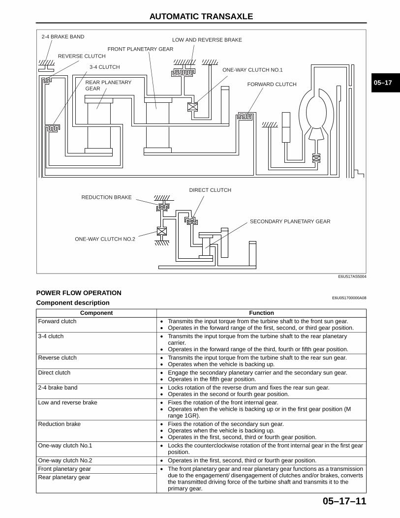
E6U051700000A08Component description
SECONDARY PLANETARY GEAR
DIRECT CLUTCH
ONE-WAY CLUTCH NO.2
REDUCTION BRAKE
REAR PLANETARY GEAR
3-4 CLUTCH
REVERSE CLUTCH
2-4 BRAKE BAND
FRONT PLANETARY GEAR
LOW AND REVERSE BRAKE
ONE-WAY CLUTCH NO.1
FORWARD CLUTCH
E6U517AS5004
Component FunctionForward clutch • Transmits the input torque from the turbine shaft to the front sun gear.
• Operates in the forward range of the first, second, or third gear position.3-4 clutch • Transmits the input torque from the turbine shaft to the rear planetary
carrier.• Operates in the forward range of the third, fourth or fifth gear position.
Reverse clutch • Transmits the input torque from the turbine shaft to the rear sun gear.• Operates when the vehicle is backing up.
Direct clutch • Engage the secondary planetary carrier and the secondary sun gear.• Operates in the fifth gear position.
2-4 brake band • Locks rotation of the reverse drum and fixes the rear sun gear.• Operates in the second or fourth gear position.
Low and reverse brake • Fixes the rotation of the front internal gear.• Operates when the vehicle is backing up or in the first gear position (M
range 1GR).Reduction brake • Fixes the rotation of the secondary sun gear.
• Operates when the vehicle is backing up.• Operates in the first, second, third or fourth gear position.
One-way clutch No.1 • Locks the counterclockwise rotation of the front internal gear in the first gear position.
One-way clutch No.2 • Operates in the first, second, third or fourth gear position.Front planetary gear • The front planetary gear and rear planetary gear functions as a transmission
due to the engagement/ disengagement of clutches and/or brakes, converts the transmitted driving force of the turbine shaft and transmits it to the primary gear.
Rear planetary gear
AUTOMATIC TRANSAXLE
05–17–12
Note• All directions of rotation are viewed from the torque converter.
1GR (D range)
Secondary planetary gear • The secondary planetary gear functions as a transmission due to the engagement/ disengagement of clutches and/or brakes, converts the transmitted driving force of the turbine shaft and transmits it to the output gear.
Component Function
A
A
OUTPUT
RING GEAR (DIFFERENTIAL)
OUTPUT GEAR
SECONDARY INTERNAL GEAR
SECONDARY SUN GEAR
ONE-WAY CLUTCH NO.2
REDUCTION BRAKE
SECONDARY PINION GEARSECONDARY GEAR
PRIMARY GEAR
FRONT INTERNAL GEAR
FRONT PINION GEAR
FRONT SUN GEAR
FRONT PLANETARY CARRIER
ONE-WAY CLUTCH NO.1
FORWARD CLUTCH
INPUT
E6U517AS5005

AUTOMATIC TRANSAXLE
05–17–13
05–17
A
A
OUTPUT
SECONDARY PLANETARY CARRIER
OUTPUT GEAR
SECONDARY INTERNAL GEAR
SECONDARY SUN GEAR
ONE-WAY CLUTCH NO.2
REDUCTION BRAKE
SECONDARY PINION GEAR
SECONDARY GEAR
PRIMARY GEARFRONT INTERNAL GEAR
FRONT PINION GEAR
FRONT SUN GEARFRONT PLANETARY CARRIER
ONE-WAY CLUTCH NO.1
FORWARD CLUTCH
INPUT
E6U517AS5006
AUTOMATIC TRANSAXLE
05–17–14
1GR (M range)
A
A
OUTPUT
RING GEAR (DIFFERENTIAL)
OUTPUT GEAR
SECONDARY INTERNAL GEAR
SECONDARY SUN GEAR
ONE-WAY CLUTCH NO.2
REDUCTION BRAKE
SECONDARY PINION GEAR
SECONDARY GEAR
FRONT INTERNAL GEAR
FRONT PINION GEAR
FRONT SUN GEAR
FRONT PLANETARY CARRIER
PRIMARY GEAR
LOW AND REVERSE BRAKE
ONE-WAY CLUTCH NO.1
FORWARD CLUTCH
INPUT
E6U517AS5007
AUTOMATIC TRANSAXLE
05–17–15
05–17
A
A
OUTPUT
SECONDARY PLANETARY CARRIER
OUTPUT GEAR
SECONDARY INTERNAL GEAR
ONE-WAY CLUTCH NO.2
REDUCTION BRAKE
SECONDARY SUN GEAR
SECONDARY PINION GEAR
SECONDARY GEAR
PRIMARY GEARFRONT INTERNAL GEAR
FRONT PINION GEAR
FRONT SUN GEARFRONT PLANETARY CARRIER
LOW AND REVERSE BRAKE
ONE-WAY CLUTCH NO.1
FORWARD CLUTCH
INPUT
E6U517AS5008
AUTOMATIC TRANSAXLE
05–17–16
2GR
A
A
OUTPUT
RING GEAR (DIFFERENTIAL)
OUTPUT GEAR
SECONDARY INTERNAL GEAR
SECONDARY SUN GEAR
ONE-WAY CLUTCH NO.2
REDUCTION BRAKE
SECONDARY PINION GEAR
SECONDARY GEAR
PRIMARY GEAR
FRONT INTERNAL GEAR
FRONT PINION GEAR
FRONT SUN GEAR
FRONT PLANETARY CARRIER
2-4 BRAKE BAND
REAR SUN GEAR
REAR PINION GEAR
REAR PLANETARY CARRIER
REAR INTERNAL GEAR
FORWARD CLUTCH
INPUT
E6U517AS5009
AUTOMATIC TRANSAXLE
05–17–17
05–17
A
A
OUTPUT
SECONDARY PLANETARY CARRIER
OUTPUT GEAR
SECONDARY SUN GEAR
SECONDARY INTERNAL GEAR
ONE-WAY CLUTCH NO.2
REDUCTION BRAKE
SECONDARY PINION GEAR
SECONDARY GEAR
FRONT INTERNAL GEAR
PRIMARY GEAR
FRONT PINION GEAR
FRONT SUN GEAR
FRONT PLANETARY CARRIER
2-4 BRAKE BAND
REAR SUN GEAR
REAR PINION GEAR
REAR PLANETARY CARRIER
REAR INTERNAL GEAR
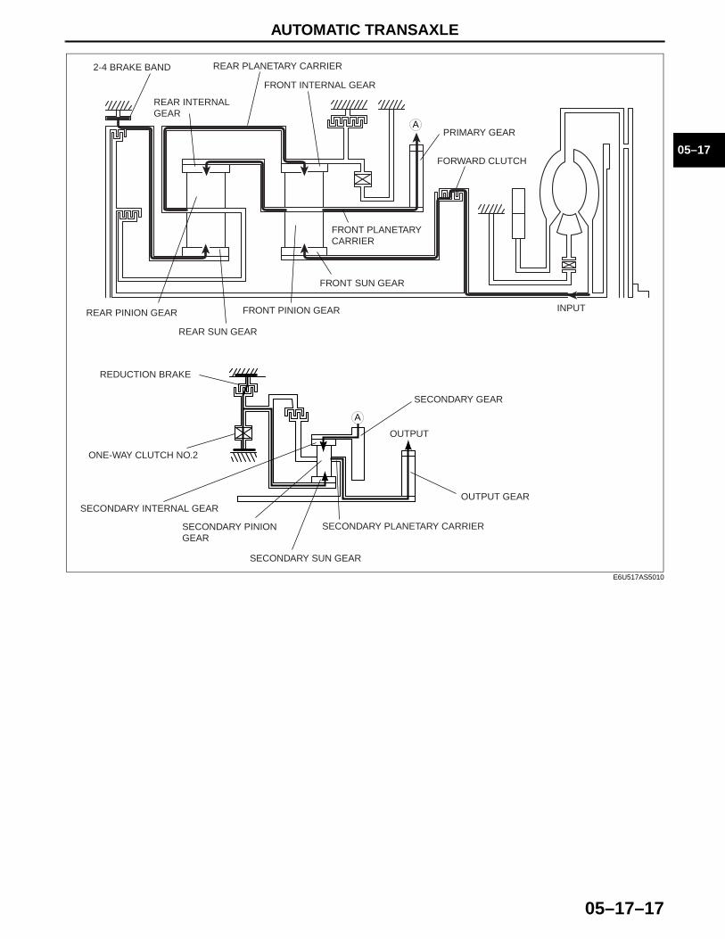
FORWARD CLUTCH
INPUT
E6U517AS5010
AUTOMATIC TRANSAXLE
05–17–18
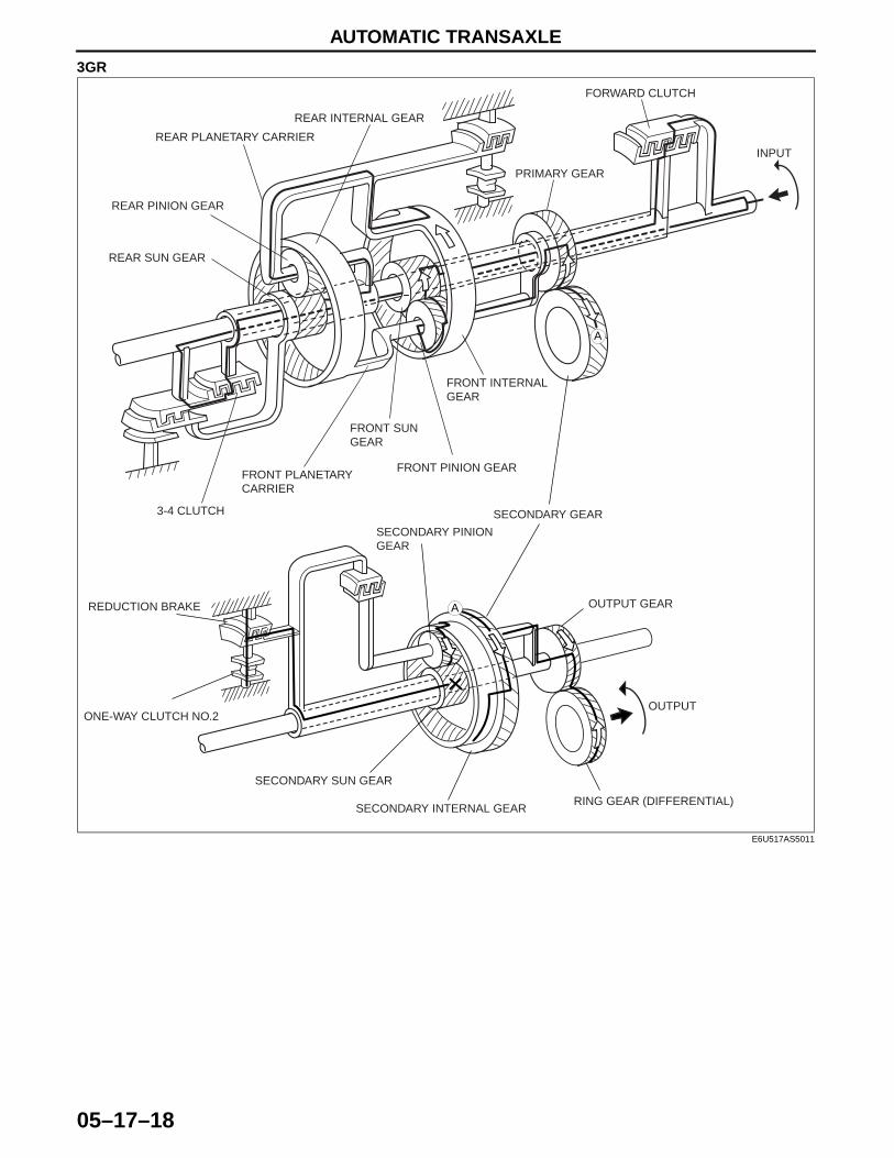
3GR
A
A
OUTPUT
RING GEAR (DIFFERENTIAL)
OUTPUT GEAR
SECONDARY INTERNAL GEAR
SECONDARY SUN GEAR
ONE-WAY CLUTCH NO.2
REDUCTION BRAKE
SECONDARY PINION GEAR
SECONDARY GEAR
PRIMARY GEAR
FRONT INTERNAL GEAR
FRONT PINION GEAR
FRONT SUN GEAR
FRONT PLANETARY CARRIER
3-4 CLUTCH
REAR SUN GEAR
REAR PINION GEAR
REAR PLANETARY CARRIER
REAR INTERNAL GEAR
FORWARD CLUTCH
INPUT
E6U517AS5011
AUTOMATIC TRANSAXLE
05–17–19
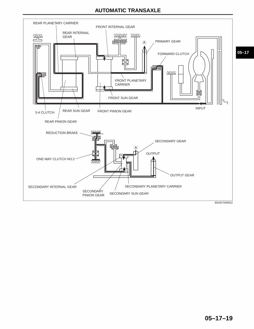
05–17
A
A
OUTPUT
SECONDARY PLANETARY CARRIER
OUTPUT GEAR
SECONDARY INTERNAL GEAR
SECONDARY SUN GEAR
ONE-WAY CLUTCH NO.2
REDUCTION BRAKE
SECONDARY PINION GEAR
SECONDARY GEAR
PRIMARY GEAR
FRONT INTERNAL GEAR
FRONT PINION GEAR
FRONT SUN GEAR
FRONT PLANETARY CARRIER
3-4 CLUTCH REAR SUN GEAR
REAR PINION GEAR
REAR PLANETARY CARRIER
REAR INTERNAL GEAR
FORWARD CLUTCH
INPUT
E6U517AS5012
AUTOMATIC TRANSAXLE
05–17–20
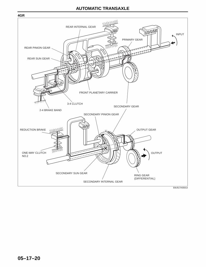
4GR
A
A
OUTPUT
RING GEAR (DIFFERENTIAL)
OUTPUT GEAR
SECONDARY INTERNAL GEAR
SECONDARY SUN GEAR
ONE-WAY CLUTCH NO.2
REDUCTION BRAKE
SECONDARY PINION GEAR
SECONDARY GEAR
PRIMARY GEAR
FRONT PLANETARY CARRIER
3-4 CLUTCH
2-4 BRAKE BAND
REAR SUN GEAR
REAR PINION GEAR
REAR INTERNAL GEAR
INPUT
E6U517AS5013
AUTOMATIC TRANSAXLE
05–17–21
05–17
A
A
OUTPUT
SECONDARY PLANETARY CARRIER
OUTPUT GEAR
SECONDARY INTERNAL GEAR
SECONDARY SUN GEAR
ONE-WAY CLUTCH NO.2
REDUCTION BRAKE
SECONDARY PINION GEAR
SECONDARY GEAR
PRIMARY GEAR
FRONT PLANETARY CARRIER
3-4 CLUTCH
2-4 BRAKE BAND
REAR SUN GEAR
REAR PINION GEAR
REAR INTERNAL GEAR
INPUT
E6U517AS5014
AUTOMATIC TRANSAXLE
05–17–22
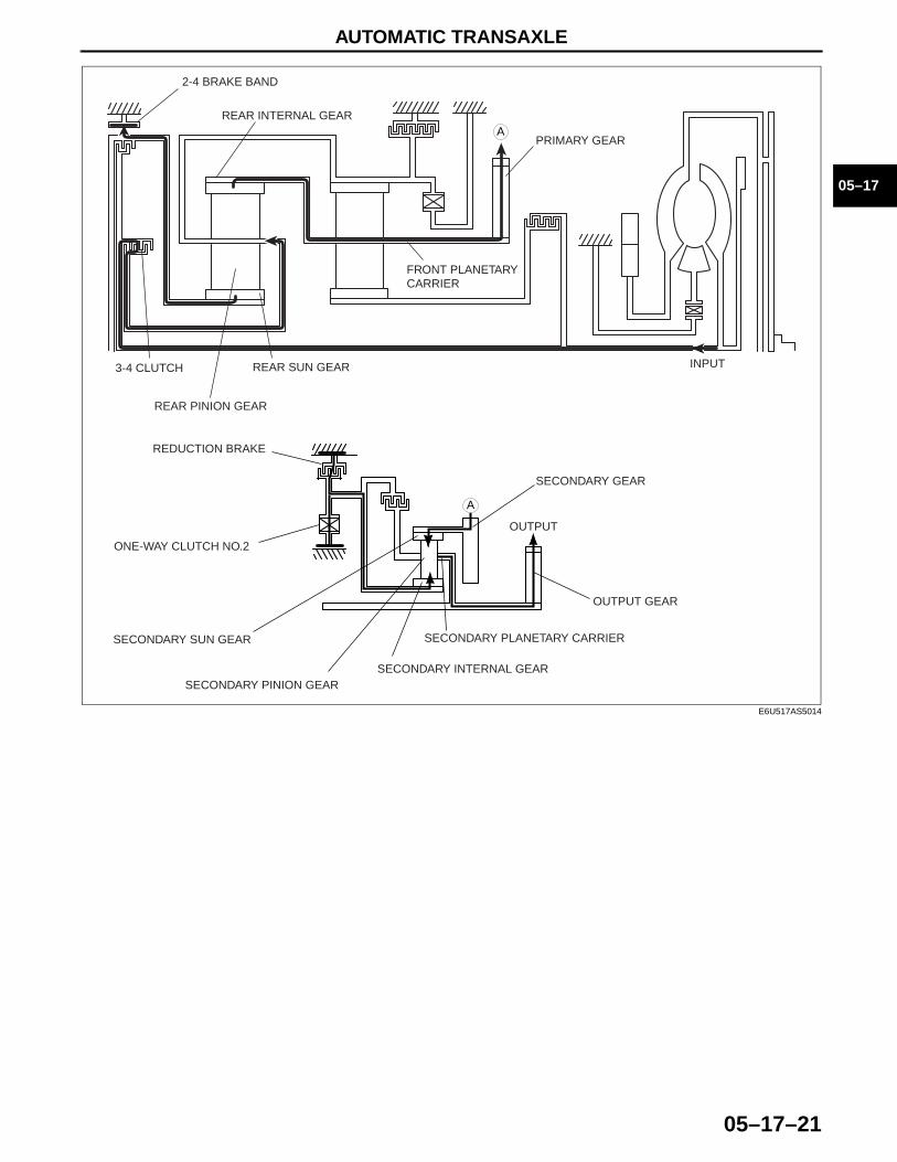
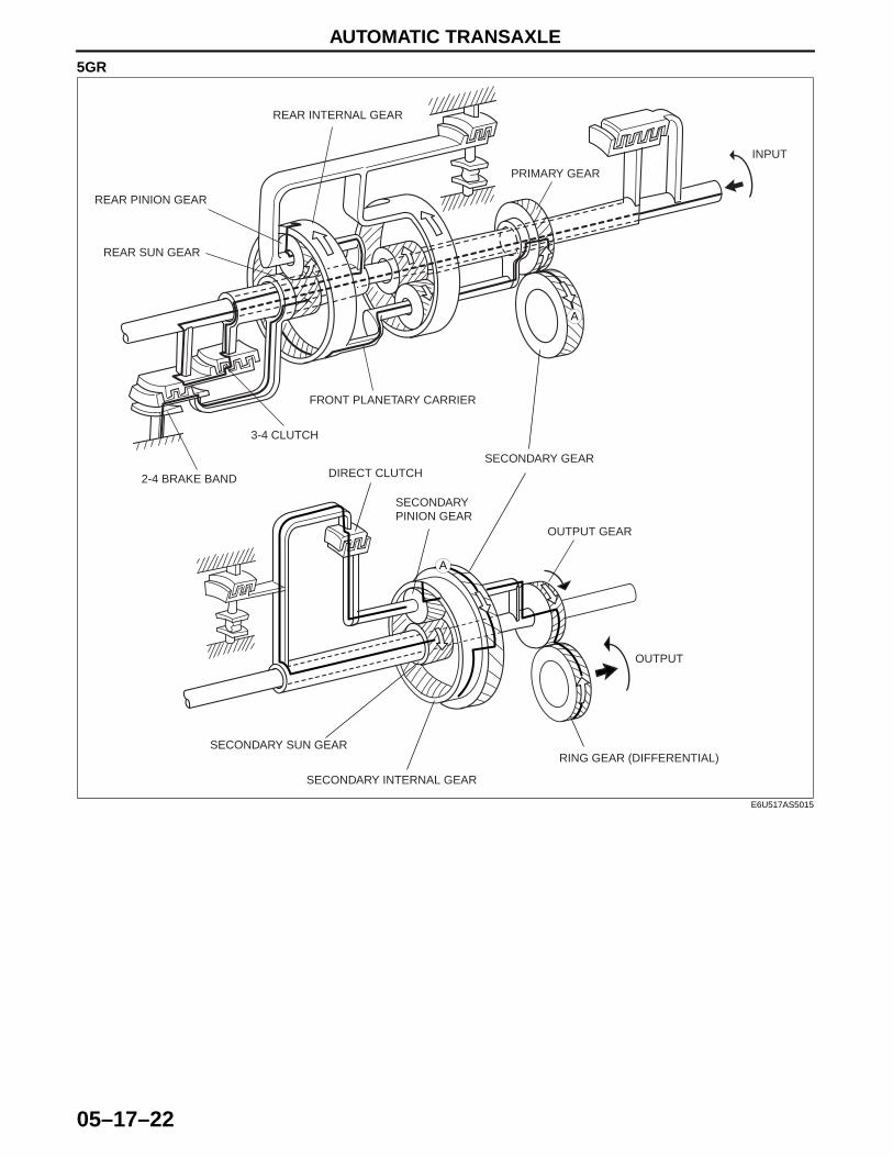
5GR
A
A
OUTPUT
RING GEAR (DIFFERENTIAL)
OUTPUT GEAR
SECONDARY INTERNAL GEAR
SECONDARY SUN GEAR
DIRECT CLUTCH
SECONDARY PINION GEAR
SECONDARY GEAR
PRIMARY GEAR
FRONT PLANETARY CARRIER
3-4 CLUTCH
2-4 BRAKE BAND
REAR SUN GEAR
REAR PINION GEAR
REAR INTERNAL GEAR
INPUT
E6U517AS5015
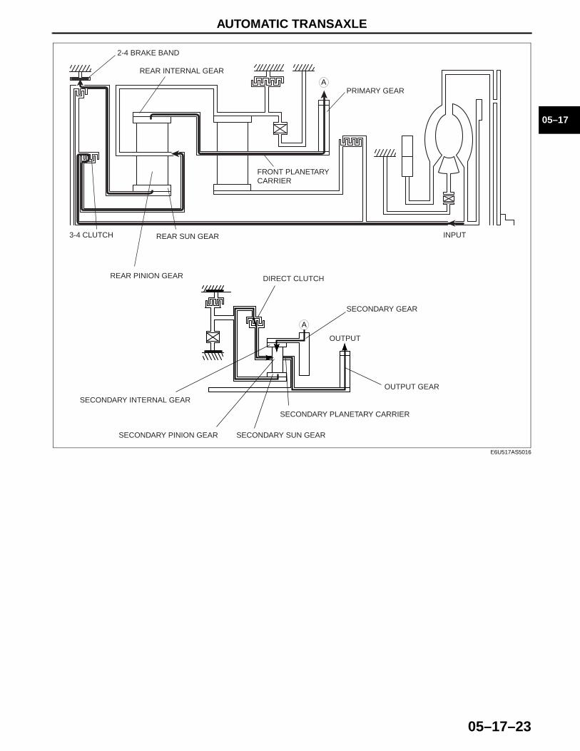
AUTOMATIC TRANSAXLE
05–17–23
05–17
A
A
OUTPUT
SECONDARY PLANETARY CARRIER
OUTPUT GEAR
SECONDARY INTERNAL GEAR
SECONDARY SUN GEAR
DIRECT CLUTCH
SECONDARY PINION GEAR
SECONDARY GEAR
PRIMARY GEAR
FRONT PLANETARY CARRIER
3-4 CLUTCH
2-4 BRAKE BAND
REAR SUN GEAR
REAR PINION GEAR
REAR INTERNAL GEAR
INPUT
E6U517AS5016
AUTOMATIC TRANSAXLE
05–17–24
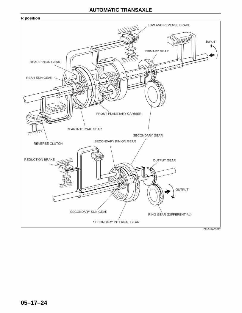
R position
A
A
OUTPUT
RING GEAR (DIFFERENTIAL)
OUTPUT GEAR
SECONDARY INTERNAL GEAR
SECONDARY SUN GEAR
REDUCTION BRAKE
SECONDARY PINION GEAR
SECONDARY GEAR
PRIMARY GEAR
FRONT PLANETARY CARRIER
REAR INTERNAL GEAR
REAR PINION GEAR
REAR SUN GEAR
REVERSE CLUTCH
LOW AND REVERSE BRAKE
INPUT
E6U517AS5017
AUTOMATIC TRANSAXLE
05–17–25
05–17
End Of Sie
A
A
OUTPUT
SECONDARY PLANETARY CARRIER
OUTPUT GEAR
SECONDARY INTERNAL GEAR
SECONDARY SUN GEAR
REDUCTION BRAKE
SECONDARY PINION GEAR
SECONDARY GEAR
PRIMARY GEAR
FRONT PLANETARY CARRIER
REAR INTERNAL GEAR
REAR PINION GEAR
REAR SUN GEAR
REVERSE CLUTCH LOW AND REVERSE BRAKE
INPUT
E6U517AS5018
AUTOMATIC TRANSAXLE
05–17–26
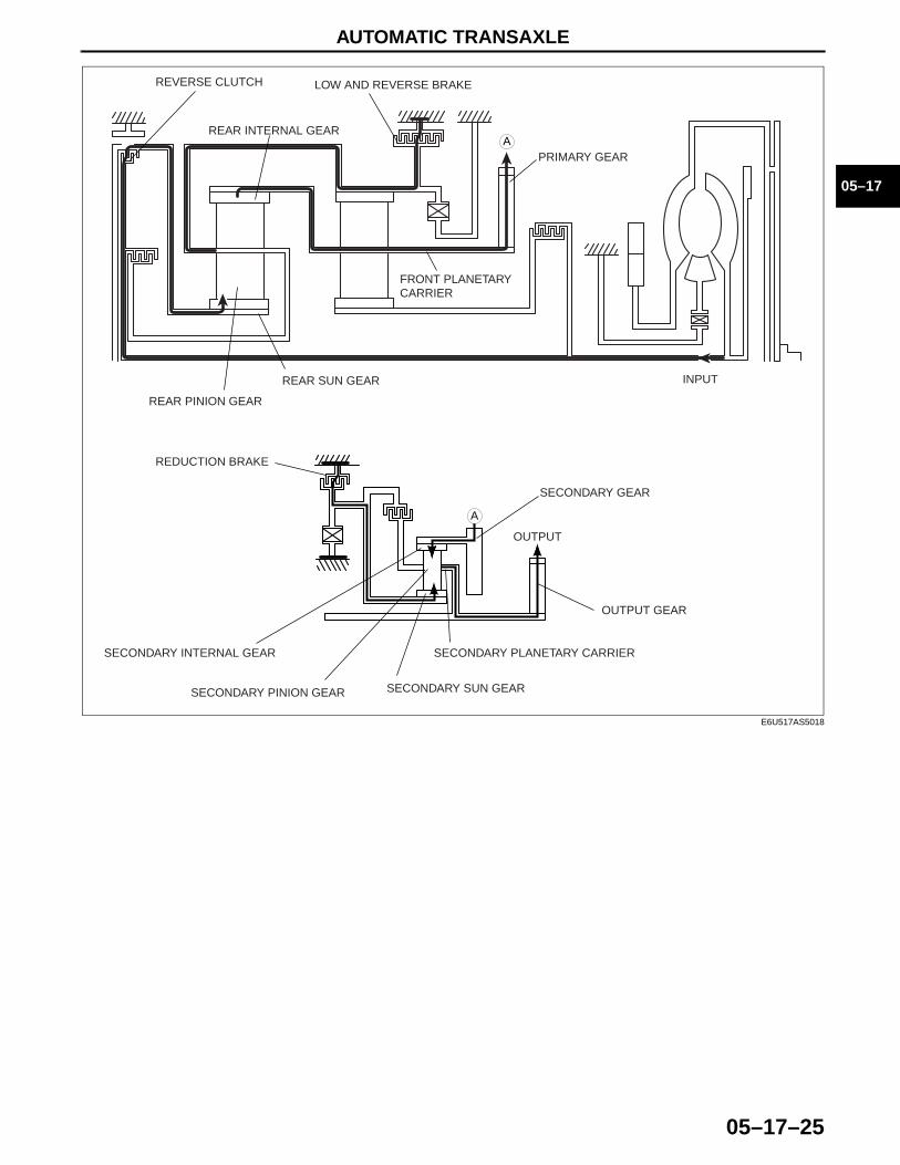
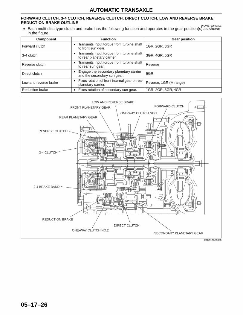
FORWARD CLUTCH, 3-4 CLUTCH, REVERSE CLUTCH, DIRECT CLUTCH, LOW AND REVERSE BRAKE, REDUCTION BRAKE OUTLINE
E6U051719500A01• Each multi-disc type clutch and brake has the following function and operates in the gear position(s) as shown
in the figure.
End Of Sie
Component Function Gear position
Forward clutch • Transmits input torque from turbine shaft to front sun gear. 1GR, 2GR, 3GR
3-4 clutch • Transmits input torque from turbine shaft to rear planetary carrier. 3GR, 4GR, 5GR
Reverse clutch • Transmits input torque from turbine shaft to rear sun gear. Reverse
Direct clutch • Engage the secondary planetary carrier and the secondary sun gear. 5GR
Low and reverse brake • Fixes rotation of front internal gear or rear planetary carrier. Reverse, 1GR (M range)
Reduction brake • Fixes rotation of secondary sun gear. 1GR, 2GR, 3GR, 4GR
SECONDARY PLANETARY GEAR
DIRECT CLUTCH
ONE-WAY CLUTCH NO.2
REDUCTION BRAKE
2-4 BRAKE BAND
3-4 CLUTCH
REVERSE CLUTCH
REAR PLANETARY GEAR
FRONT PLANETARY GEAR
LOW AND REVERSE BRAKE
ONE-WAY CLUTCH NO.1
FORWARD CLUTCH
E6U517AS5003
AUTOMATIC TRANSAXLE
05–17–27
05–17
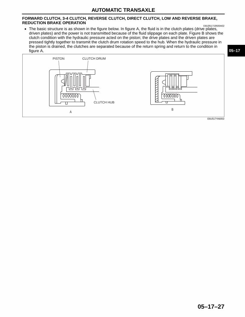
FORWARD CLUTCH, 3-4 CLUTCH, REVERSE CLUTCH, DIRECT CLUTCH, LOW AND REVERSE BRAKE, REDUCTION BRAKE OPERATION
E6U051719500A02• The basic structure is as shown in the figure below. In figure A, the fluid is in the clutch plates (drive plates,
driven plates) and the power is not transmitted because of the fluid slippage on each plate. Figure B shows the clutch condition with the hydraulic pressure acted on the piston; the drive plates and the driven plates are pressed tightly together to transmit the clutch drum rotation speed to the hub. When the hydraulic pressure in the piston is drained, the clutches are separated because of the return spring and return to the condition in figure A.
AB
PISTON CLUTCH DRUM
CLUTCH HUB
E6U517YA6002
AUTOMATIC TRANSAXLE
05–17–28
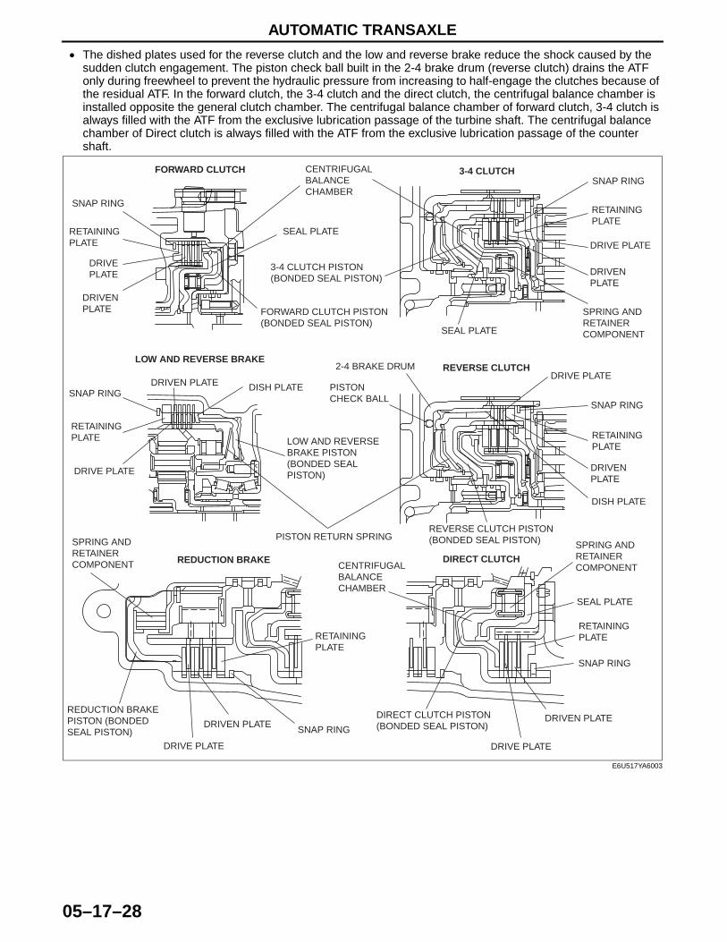
• The dished plates used for the reverse clutch and the low and reverse brake reduce the shock caused by the sudden clutch engagement. The piston check ball built in the 2-4 brake drum (reverse clutch) drains the ATF only during freewheel to prevent the hydraulic pressure from increasing to half-engage the clutches because of the residual ATF. In the forward clutch, the 3-4 clutch and the direct clutch, the centrifugal balance chamber is installed opposite the general clutch chamber. The centrifugal balance chamber of forward clutch, 3-4 clutch is always filled with the ATF from the exclusive lubrication passage of the turbine shaft. The centrifugal balance chamber of Direct clutch is always filled with the ATF from the exclusive lubrication passage of the counter shaft.
End Of Sie
FORWARD CLUTCH 3-4 CLUTCH
LOW AND REVERSE BRAKEREVERSE CLUTCH
REDUCTION BRAKE DIRECT CLUTCH
SNAP RING
SNAP RING
SNAP RINGSNAP RING
SNAP RING
SNAP RING
RETAINING PLATE
RETAINING PLATE
RETAINING PLATE RETAINING
PLATE
RETAINING PLATE
RETAINING PLATE
DRIVE PLATEDRIVE PLATE
DRIVE PLATE
DRIVE PLATE
DRIVE PLATE
DRIVE PLATE
DRIVEN PLATE
DRIVEN PLATE
DRIVEN PLATE
DRIVEN PLATE
DRIVEN PLATEDRIVEN PLATE
CENTRIFUGAL BALANCE CHAMBER
CENTRIFUGAL BALANCE CHAMBER
SEAL PLATE
SEAL PLATE
SEAL PLATE
FORWARD CLUTCH PISTON (BONDED SEAL PISTON)
SPRING AND RETAINER COMPONENT
SPRING AND RETAINER COMPONENT
SPRING AND RETAINER COMPONENT
3-4 CLUTCH PISTON (BONDED SEAL PISTON)
DISH PLATE
DISH PLATE
LOW AND REVERSE BRAKE PISTON (BONDED SEAL PISTON)
PISTON RETURN SPRING
2-4 BRAKE DRUM
PISTON CHECK BALL
REVERSE CLUTCH PISTON (BONDED SEAL PISTON)
REDUCTION BRAKE PISTON (BONDED SEAL PISTON)
DIRECT CLUTCH PISTON (BONDED SEAL PISTON)
E6U517YA6003

AUTOMATIC TRANSAXLE
05–17–29
05–17
CENTRIFUGAL BALANCE CLUTCH OUTLINEE6U051719500A03
• A centrifugal balance clutch mechanism, which cancels the centrifugal oil pressure, has been adopted to improve clutch control.
• A bonded seal piston (press-worked component of a piston and a seal) has been adopted for each clutch and brake to reduce the piston size and weight.
End Of SieCENTRIFUGAL BALANCE CLUTCH STRUCTURE
E6U051719500A04• The centrifugal balance clutch chambers are installed opposite the clutch chamber. The centrifugal balance
clutch chambers are constantly filled with ATF from an exclusive hydraulic passage of the turbine shaft.End Of SieCENTRIFUGAL BALANCE CLUTCH OPERATION
E6U051719500A05When clutch pressure is not applied• When the clutch drum rotates, centrifugal force acts on the residual ATF in the clutch chamber to push against
the piston. However, centrifugal force also acts on the ATF filling the centrifugal balance clutch chamber to push back the piston. As a result, the two forces are cancelled out and the piston remains stationary, thus preventing clutch engagement.
When clutch pressure is applied• When clutch pressure is applied to the clutch chamber, the clutch pressure overcomes the oil pressure and
spring force in the opposite centrifugal balance clutch chamber, and pushes the piston to engage the clutches. Because the centrifugal force acting on the clutch pressure in the clutch chamber is canceled by another centrifugal force acting on the ATF filling the centrifugal balance clutch chamber, the influence of the centrifugal force created by the clutch drum revolution speed is eliminated. As a result, stable piston pushing force is obtained in all rotation ranges, and smoother shifts can be made.
End Of Sie
3 3
3
1
1
2
2
CHANGES ACCORDING TO THE ROTATION SPEED OF CLUTCH DRUM
CENTRIFUGAL HYDRAULIC PRESSURE OF BALANCE CHAMBER
SPRING FORCE
TWO FORCES CANCEL OUT
DRUM REVOLUTION SPEED
PISTON PUSHING FORCE
PISTON PUSHING FORCE REQUIRED TO OBTAIN SHIFT QUALITY
CENTRIFUGAL HYDRAULIC PRESSURE OF PISTON CHAMBER
CLUTCH PRESSURE
LUBRICATION PASSAGE
SEAL PLATE
BALANCE CHAMBER
BONDED SEAL PISTON
CLUTCH CHAMBER
CLUTCH PRESSURE
CLUTCH PRESSURE
SEAL
SEAL
CLUTCH
CLUTCH DRUM
OPERATIONSTRUCTURE
E6U517AS5019
AUTOMATIC TRANSAXLE
05–17–30
2-4 BRAKE BAND OUTLINEE6U051719500A06
• The 2-4 brake band locks the 2-4 brake drum and fixes the rear sun gear. The 2-4 brake band operates in 2GR, 4GR or 5GR.
End Of Sie2-4 BRAKE BAND STRUCTURE
E6U051719500A07• The 2-4 brake band is set to wind the 2-4 brake drum and one end of the 2-4 brake band is fixed with a band
strut. The servo piston is in the transaxle case.End Of Sie2-4 BRAKE BAND OPERATION
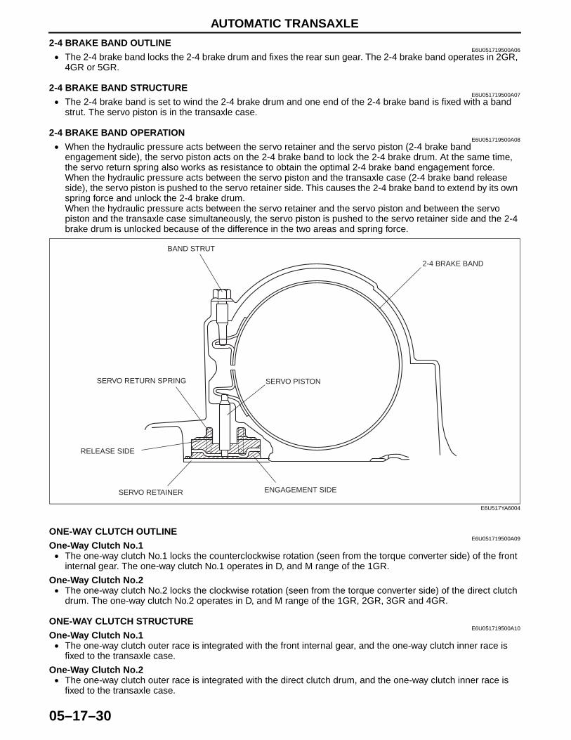
E6U051719500A08• When the hydraulic pressure acts between the servo retainer and the servo piston (2-4 brake band
engagement side), the servo piston acts on the 2-4 brake band to lock the 2-4 brake drum. At the same time, the servo return spring also works as resistance to obtain the optimal 2-4 brake band engagement force.When the hydraulic pressure acts between the servo piston and the transaxle case (2-4 brake band release side), the servo piston is pushed to the servo retainer side. This causes the 2-4 brake band to extend by its own spring force and unlock the 2-4 brake drum.When the hydraulic pressure acts between the servo retainer and the servo piston and between the servo piston and the transaxle case simultaneously, the servo piston is pushed to the servo retainer side and the 2-4 brake drum is unlocked because of the difference in the two areas and spring force.
End Of SieONE-WAY CLUTCH OUTLINE
E6U051719500A09One-Way Clutch No.1• The one-way clutch No.1 locks the counterclockwise rotation (seen from the torque converter side) of the front
internal gear. The one-way clutch No.1 operates in D, and M range of the 1GR.
One-Way Clutch No.2• The one-way clutch No.2 locks the clockwise rotation (seen from the torque converter side) of the direct clutch
drum. The one-way clutch No.2 operates in D, and M range of the 1GR, 2GR, 3GR and 4GR.End Of SieONE-WAY CLUTCH STRUCTURE
E6U051719500A10One-Way Clutch No.1• The one-way clutch outer race is integrated with the front internal gear, and the one-way clutch inner race is
fixed to the transaxle case.
One-Way Clutch No.2• The one-way clutch outer race is integrated with the direct clutch drum, and the one-way clutch inner race is
fixed to the transaxle case.End Of Sie
BAND STRUT
SERVO RETURN SPRING
RELEASE SIDE
SERVO RETAINER ENGAGEMENT SIDE
SERVO PISTON
2-4 BRAKE BAND
E6U517YA6004

AUTOMATIC TRANSAXLE
05–17–31
05–17
ONE-WAY CLUTCH OPERATIONE6U051719500A11
One-Way Clutch No.1• The one-way clutch outer race (front internal gear) rotates clockwise (seen from the torque converter side)
freely, but the sprags rise to lock the rotation when the outer race tries to rotate counterclockwise.• The one-way clutch No.1 locks the counterclockwise rotation of the front internal gear, and also locks the
counterclockwise revolution of the rear planetary gear via the rear planetary carrier.
Note• All direction of rotation are viewed from the torque converter.
ONE-WAY CLUTCH OUTER RACE (FRONT INTERNAL GEAR) CANNOT ROTATE
ONE-WAY CLUTCH OUTER RACE (FRONT INTERNAL GEAR) CAN ROTATE
ONE-WAY CLUTCH INNER RACE (FIXED TO TRANSAXLE CASE)
ONE-WAY CLUTCH INNER RACE (FIXED TO TRANSAXLE CASE)
ONE-WAY CLUTCH OUTER RACE (FRONT INTERNAL GEAR) ONE-WAY CLUTCH NO.1
ONE-WAY CLUTCH INNER RACE TRANSAXLE CASE
E6U517YA6005
AUTOMATIC TRANSAXLE
05–17–32
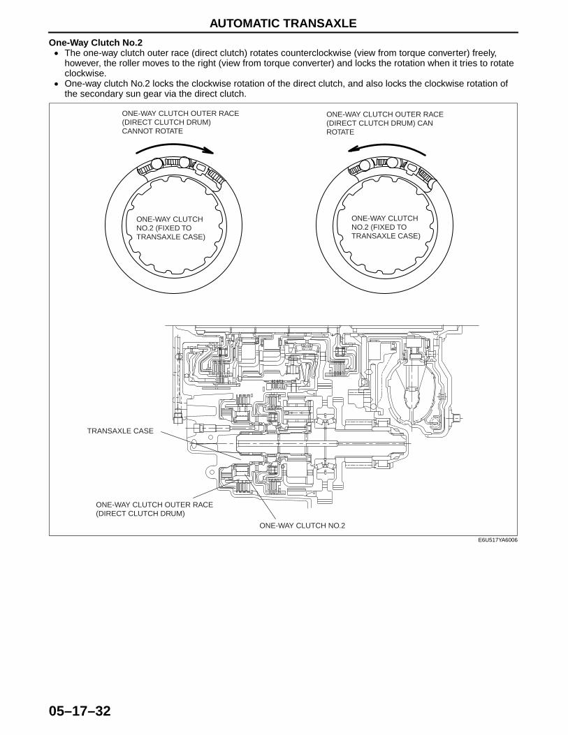
One-Way Clutch No.2• The one-way clutch outer race (direct clutch) rotates counterclockwise (view from torque converter) freely,
however, the roller moves to the right (view from torque converter) and locks the rotation when it tries to rotate clockwise.
• One-way clutch No.2 locks the clockwise rotation of the direct clutch, and also locks the clockwise rotation of the secondary sun gear via the direct clutch.
End Of Sie
ONE-WAY CLUTCH OUTER RACE (DIRECT CLUTCH DRUM) CANNOT ROTATE
ONE-WAY CLUTCH OUTER RACE (DIRECT CLUTCH DRUM) CAN ROTATE
ONE-WAY CLUTCH NO.2 (FIXED TO TRANSAXLE CASE)
ONE-WAY CLUTCH NO.2 (FIXED TO TRANSAXLE CASE)
TRANSAXLE CASE
ONE-WAY CLUTCH OUTER RACE (DIRECT CLUTCH DRUM)
ONE-WAY CLUTCH NO.2
E6U517YA6006
AUTOMATIC TRANSAXLE
05–17–33
05–17
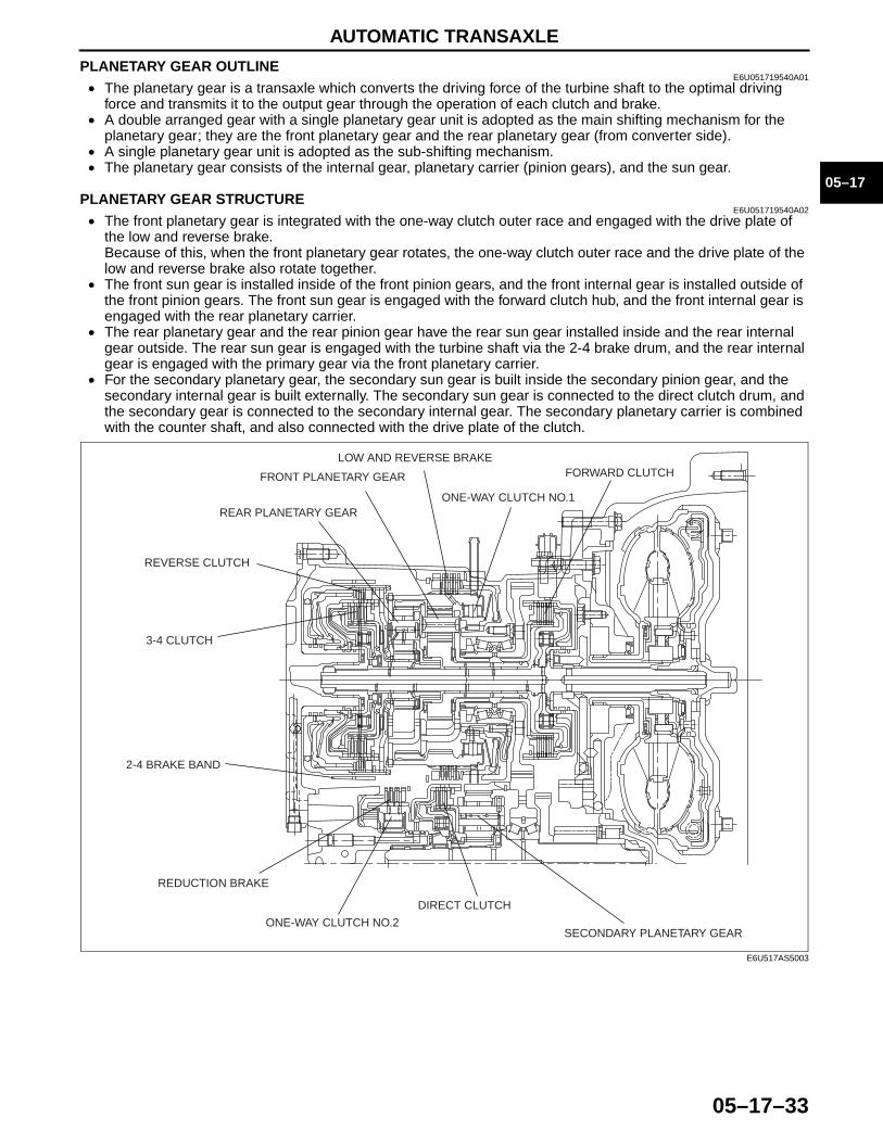
PLANETARY GEAR OUTLINEE6U051719540A01
• The planetary gear is a transaxle which converts the driving force of the turbine shaft to the optimal driving force and transmits it to the output gear through the operation of each clutch and brake.
• A double arranged gear with a single planetary gear unit is adopted as the main shifting mechanism for the planetary gear; they are the front planetary gear and the rear planetary gear (from converter side).
• A single planetary gear unit is adopted as the sub-shifting mechanism.• The planetary gear consists of the internal gear, planetary carrier (pinion gears), and the sun gear.
End Of SiePLANETARY GEAR STRUCTURE
E6U051719540A02• The front planetary gear is integrated with the one-way clutch outer race and engaged with the drive plate of
the low and reverse brake.Because of this, when the front planetary gear rotates, the one-way clutch outer race and the drive plate of the low and reverse brake also rotate together.
• The front sun gear is installed inside of the front pinion gears, and the front internal gear is installed outside of the front pinion gears. The front sun gear is engaged with the forward clutch hub, and the front internal gear is engaged with the rear planetary carrier.
• The rear planetary gear and the rear pinion gear have the rear sun gear installed inside and the rear internal gear outside. The rear sun gear is engaged with the turbine shaft via the 2-4 brake drum, and the rear internal gear is engaged with the primary gear via the front planetary carrier.
• For the secondary planetary gear, the secondary sun gear is built inside the secondary pinion gear, and the secondary internal gear is built externally. The secondary sun gear is connected to the direct clutch drum, and the secondary gear is connected to the secondary internal gear. The secondary planetary carrier is combined with the counter shaft, and also connected with the drive plate of the clutch.
End Of Sie
SECONDARY PLANETARY GEAR
DIRECT CLUTCH
ONE-WAY CLUTCH NO.2
REDUCTION BRAKE
2-4 BRAKE BAND
3-4 CLUTCH
REVERSE CLUTCH
REAR PLANETARY GEAR
FRONT PLANETARY GEAR
LOW AND REVERSE BRAKE
ONE-WAY CLUTCH NO.1
FORWARD CLUTCH
E6U517AS5003
AUTOMATIC TRANSAXLE
05–17–34
PLANETARY GEAR OPERATIONE6U051719540A03
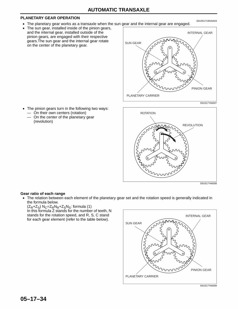
• The planetary gear works as a transaxle when the sun gear and the internal gear are engaged.• The sun gear, installed inside of the pinion gears,
and the internal gear, installed outside of the pinion gears, are engaged with their respective gears.The sun gear and the internal gear rotate on the center of the planetary gear.
• The pinion gears turn in the following two ways:— On their own centers (rotation)— On the center of the planetary gear
(revolution)
Gear ratio of each range• The relation between each element of the planetary gear set and the rotation speed is generally indicated in
the formula below.(ZR+ZS) NC=ZRNR+ZSNS: formula (1)In this formula Z stands for the number of teeth, N stands for the rotation speed, and R, S, C stand for each gear element (refer to the table below).
SUN GEAR
INTERNAL GEAR
PLANETARY CARRIER
PINION GEAR
E6U517YA6007
ROTATION
REVOLUTION
E6U517YA6008
SUN GEAR
INTERNAL GEAR
PLANETARY CARRIER
PINION GEAR
E6U517YA6009
AUTOMATIC TRANSAXLE
05–17–35
05–17
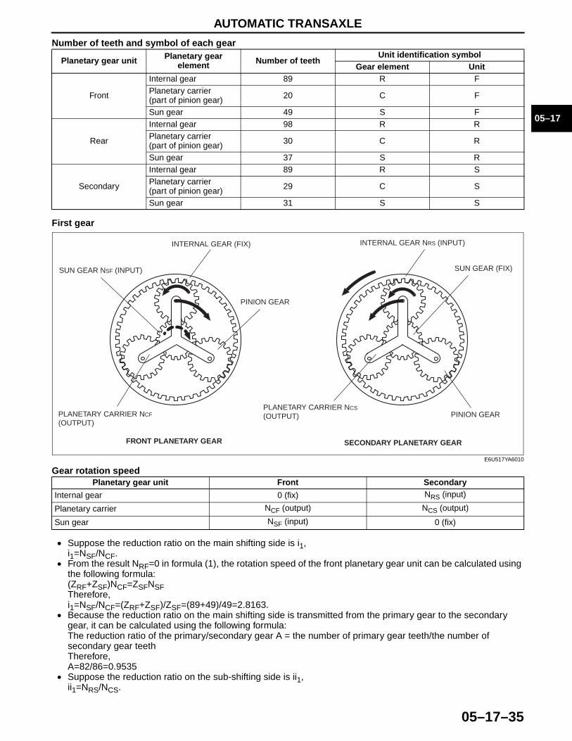
Number of teeth and symbol of each gear
First gear
Gear rotation speed
• Suppose the reduction ratio on the main shifting side is i1, i1=NSF/NCF.
• From the result NRF=0 in formula (1), the rotation speed of the front planetary gear unit can be calculated using the following formula:(ZRF+ZSF)NCF=ZSFNSFTherefore, i1=NSF/NCF=(ZRF+ZSF)/ZSF=(89+49)/49=2.8163.
• Because the reduction ratio on the main shifting side is transmitted from the primary gear to the secondary gear, it can be calculated using the following formula:The reduction ratio of the primary/secondary gear A = the number of primary gear teeth/the number of secondary gear teethTherefore, A=82/86=0.9535
• Suppose the reduction ratio on the sub-shifting side is ii1, ii1=NRS/NCS.
Planetary gear unit Planetary gear element Number of teeth
Unit identification symbolGear element Unit
Front
Internal gear 89 R FPlanetary carrier (part of pinion gear) 20 C F
Sun gear 49 S F
Rear
Internal gear 98 R RPlanetary carrier (part of pinion gear) 30 C R
Sun gear 37 S R
Secondary
Internal gear 89 R SPlanetary carrier (part of pinion gear) 29 C S
Sun gear 31 S S
Planetary gear unit Front Secondary
Internal gear 0 (fix) NRS (input)
Planetary carrier NCF (output) NCS (output)
Sun gear NSF (input) 0 (fix)
FRONT PLANETARY GEAR SECONDARY PLANETARY GEAR
SUN GEAR NSF (INPUT)
INTERNAL GEAR (FIX)
PLANETARY CARRIER NCF (OUTPUT)
PINION GEAR
PINION GEAR
SUN GEAR (FIX)
INTERNAL GEAR NRS (INPUT)
PLANETARY CARRIER NCS
(OUTPUT)
E6U517YA6010

AUTOMATIC TRANSAXLE
05–17–36
• From the result NSS=0 in formula (1), the rotation speed of the secondary planetary gear unit can be calculated using the following formula.(ZRS+ZSS)NCS=ZSSNRSTherefore, ii1=NRS/NCS=(ZRS+ZSS)/ZRS=(89+31)/89=1.3483 And the reduction ratio of 1st gear= i1 x A x ii1=2.8163 x 0.9535 x 1.3483=3.620As a result, the reduction ratio of 1st gear is 3.620.
Second gear
FRONT PLANETARY GEAR REAR PLANETARY GEAR
SECONDARY PLANETARY GEAR
SUN GEAR NSF (INPUT)INTERNAL GEAR NRF=NC
PLANETARY CARRIER NCF (OUTPUT) =NR
PINION GEAR
PINION GEAR
SUN GEAR (FIX)
INTERNAL GEAR NRR (OUTPUT) =NR
PLANETARY CARRIER NCR=NC
SUN GEAR (FIX)
INTERNAL GEAR NRS (INPUT)
PLANETARY CARRIER NCS (OUTPUT)
PINION GEAR
E6U517YA6011
AUTOMATIC TRANSAXLE
05–17–37
05–17
Gear rotation speed
Note• The front internal gear and the rear planetary carrier are integrated.• The front planetary carrier and the rear internal gear rotate at the same speed.
• Suppose the reduction ratio on the main shifting side is i2, i2=NSF/NR.
• From formula (1), the relation between the gear ratio in second gear and the rotation speeds of the front and the rear planetary gar sets is indicated in formulas (2) and (3).(ZRF+ZSF) NR=ZRFNC+ZSFNSF: (2) (Front planetary gear set)(ZRR+ZSR) NC=ZRRNR+ZSRNSF: (3) (Rear planetary gear set)
• From the result NSR=0 in formula (3).NC= (ZRR/ (ZRR+ZSR)) NR: (4)
• Here we substitute formula (4) in formula (2).ZSRNSF= (((ZRR+ZSR) (ZRF+ZSF) –ZRFZRR) / (ZRR+ZSR)) NRTherefore,i2=NSF/NR= (((ZRR+ZSR) (ZRF+ZSF) –ZRFZRR) / (ZSF (ZRR+ZSR))) NR= ((98+37)(89+49) –89 x 98) / (49 (98+37)) =1.4978
• Because the reduction ratio on the main shifting side is transmitted from the primary gear to the secondary gear, it can be calculated using the following formula:The reduction ratio of the primary/secondary gear A = the number of primary gear teeth/the number of secondary gear teethTherefore, A=82/86=0.9535
• Suppose the reduction ratio on the sub-shifting side is ii2, ii2=NRS/NCS.
• From the result NSS=0 in formula (1), the rotation speed of the secondary planetary gear unit can be calculated using the following formula.(ZRS+ZSS)NCS=ZSSNRSTherefore, ii2=NRS/NCS=(ZRS+ZSS)/ZRS=(89+31)/89=1.3483 And the reduction ratio of 2nd gear= i2 x A x ii2=1.4978 x 0.9535 x 1.3483=1.925As a result, the reduction ratio of 2nd gear is 1.925.
Planetary gear Front Rear Secondary
Internal gear NRF=NC NRR (output) =NR NRS (input)
Planetary carrier NCF (output) =NR NCR=NC NCS (output)
Sun gear NSF (input) 0 (fix) 0 (fix)
AUTOMATIC TRANSAXLE
05–17–38
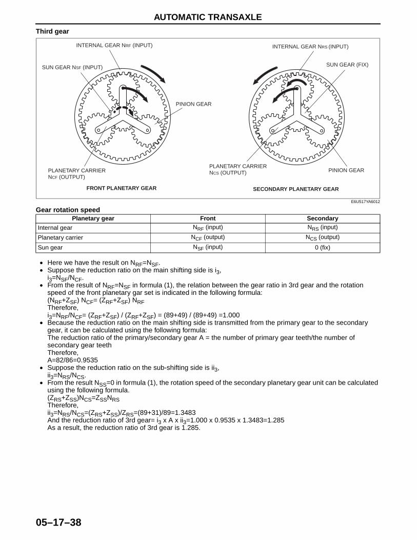
Third gear
Gear rotation speed
• Here we have the result on NRF=NSF.• Suppose the reduction ratio on the main shifting side is i3,
i3=NSF/NCF.• From the result of NRF=NSF in formula (1), the relation between the gear ratio in 3rd gear and the rotation
speed of the front planetary gar set is indicated in the following formula:(NRF+ZSF) NCF= (ZRF+ZSF) NRFTherefore,i3=NRF/NCF= (ZRF+ZSF) / (ZRF+ZSF) = (89+49) / (89+49) =1.000
• Because the reduction ratio on the main shifting side is transmitted from the primary gear to the secondary gear, it can be calculated using the following formula:The reduction ratio of the primary/secondary gear A = the number of primary gear teeth/the number of secondary gear teethTherefore, A=82/86=0.9535
• Suppose the reduction ratio on the sub-shifting side is ii3, ii3=NRS/NCS.
• From the result NSS=0 in formula (1), the rotation speed of the secondary planetary gear unit can be calculated using the following formula.(ZRS+ZSS)NCS=ZSSNRSTherefore, ii3=NRS/NCS=(ZRS+ZSS)/ZRS=(89+31)/89=1.3483 And the reduction ratio of 3rd gear= i3 x A x ii3=1.000 x 0.9535 x 1.3483=1.285As a result, the reduction ratio of 3rd gear is 1.285.
Planetary gear Front Secondary
Internal gear NRF (input) NRS (input)
Planetary carrier NCF (output) NCS (output)
Sun gear NSF (input) 0 (fix)
FRONT PLANETARY GEAR SECONDARY PLANETARY GEAR
SUN GEAR NSF (INPUT)
INTERNAL GEAR NRF (INPUT)
PLANETARY CARRIER NCF (OUTPUT)
PINION GEAR
PINION GEAR
SUN GEAR (FIX)
INTERNAL GEAR NRS (INPUT)
PLANETARY CARRIER NCS (OUTPUT)
E6U517YA6012
AUTOMATIC TRANSAXLE
05–17–39
05–17
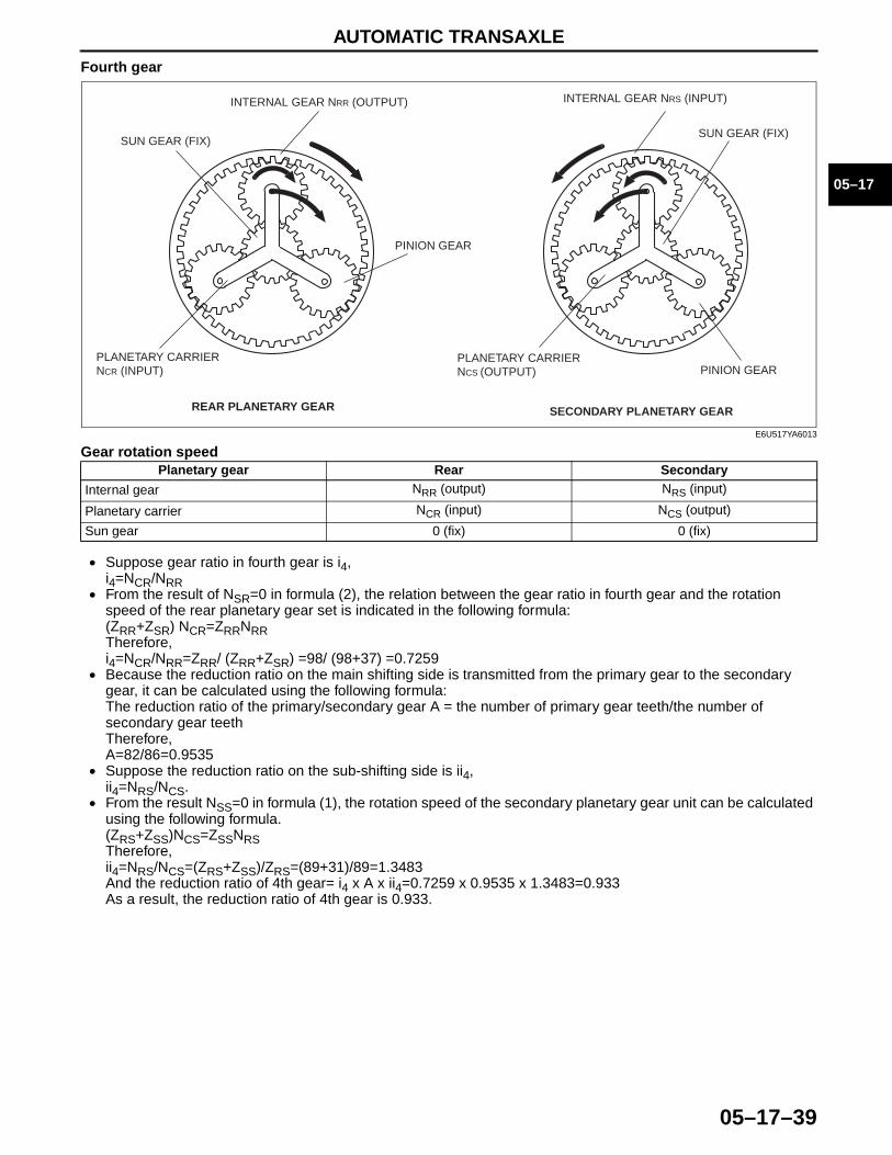
Fourth gear
Gear rotation speed
• Suppose gear ratio in fourth gear is i4,i4=NCR/NRR
• From the result of NSR=0 in formula (2), the relation between the gear ratio in fourth gear and the rotation speed of the rear planetary gear set is indicated in the following formula:(ZRR+ZSR) NCR=ZRRNRRTherefore,i4=NCR/NRR=ZRR/ (ZRR+ZSR) =98/ (98+37) =0.7259
• Because the reduction ratio on the main shifting side is transmitted from the primary gear to the secondary gear, it can be calculated using the following formula:The reduction ratio of the primary/secondary gear A = the number of primary gear teeth/the number of secondary gear teethTherefore, A=82/86=0.9535
• Suppose the reduction ratio on the sub-shifting side is ii4, ii4=NRS/NCS.
• From the result NSS=0 in formula (1), the rotation speed of the secondary planetary gear unit can be calculated using the following formula.(ZRS+ZSS)NCS=ZSSNRSTherefore, ii4=NRS/NCS=(ZRS+ZSS)/ZRS=(89+31)/89=1.3483 And the reduction ratio of 4th gear= i4 x A x ii4=0.7259 x 0.9535 x 1.3483=0.933As a result, the reduction ratio of 4th gear is 0.933.
Planetary gear Rear Secondary
Internal gear NRR (output) NRS (input)
Planetary carrier NCR (input) NCS (output)
Sun gear 0 (fix) 0 (fix)
REAR PLANETARY GEAR SECONDARY PLANETARY GEAR
SUN GEAR (FIX)
INTERNAL GEAR NRR (OUTPUT)
PLANETARY CARRIER NCR (INPUT)
PINION GEAR
SUN GEAR (FIX)
INTERNAL GEAR NRS (INPUT)
PLANETARY CARRIER NCS (OUTPUT) PINION GEAR
E6U517YA6013
AUTOMATIC TRANSAXLE
05–17–40
Fifth gear
Gear rotation speed
• Suppose gear ratio in fifth gear is i5,i5=NCR/NRR
• From the result of NSR=0 in formula (2), the relation between the gear ratio in fourth gear and the rotation speed of the rear planetary gear set is indicated in the following formula:(ZRR+ZSR) NCR=ZRRNRRTherefore,i5=NCR/NRR=ZRR/ (ZRR+ZSR) =98/ (98+37) =0.7259
• Because the reduction ratio on the main shifting side is transmitted from the primary gear to the secondary gear, it can be calculated using the following formula:The reduction ratio of the primary/secondary gear A = the number of primary gear teeth/the number of secondary gear teethTherefore, A=82/86=0.9535
• Suppose the reduction ratio on the sub-shifting side is ii5, ii5=NRS/NCS.
• From the result NRS= NSS in formula (1), the rotation speed of the secondary planetary gear unit can be calculated using the following formula.(ZRS+ZSS)NCS=(ZRSZSS)NRSTherefore, ii5=NRS/NCS=(ZRS+ZSS)/(ZRS+ZSS)=(89+31)/(89+31)=1.000 And the reduction ratio of 5th gear= i5 x A x ii5=0.7259 x 0.9535 x 1.000=0.692As a result, the reduction ratio of 5th gear is 0.692.
Planetary gear Rear Secondary
Internal gear NRR (output) NRS (input)
Planetary carrier NCR (input) NCS (output)
Sun gear 0 (fix) NSS (input)
REAR PLANETARY GEAR SECONDARY PLANETARY GEAR
SUN GEAR (FIX)
INTERNAL GEAR NRR (OUTPUT)
PLANETARY CARRIER NCR (INPUT)
PINION GEAR
PINION GEAR
SUN GEAR NSS (INPUT)
INTERNAL GEAR NRS (INPUT)
PLANETARY CARRIER NCS (OUTPUT)
E6U517YA6014
AUTOMATIC TRANSAXLE
05–17–41
05–17
Reverse
Gear rotation speed
• Suppose gear ratio in reverse gear is iREV,iREV=NSR/NRR
• From the result of NCR=0 in formula (2), the relation between the gear ratio during reverse movement and the rotation speed of the planetary gar set is indicated in the formula below.(ZRR+ZSR) 0=ZRRNRR+ZSRNSRTherefore,iREV=NSR/NRR=ZRR/ZSR=–98/37=–2.6486
• Because the reduction ratio on the main shifting side is transmitted from the primary gear to the secondary gear, it can be calculated using the following formula:The reduction ratio of the primary/secondary gear A = the number of primary gear teeth/the number of secondary gear teethTherefore, A=82/86=0.9535
• Suppose the reduction ratio on the sub-shifting side is iiREV, iiREV=NRS/NCS.
• From the result NSS=0 in formula (1), the rotation speed of the secondary planetary gear unit can be calculated using the following formula.(ZRS+ZSS)NCS=ZSSNRSTherefore, iiREV=NRS/NCS=(ZRS+ZSS)/ZRS=(89+31)/89=1.3483 And the reduction ratio of reverse gear= iREV x A x iiREV=–2.6486 x 0.9535 x 1.3483=–3.405As a result, the reduction ratio of reverse gear is –3.405.
End Of Sie
Planetary gear Rear Secondary
Internal gear NRR (output) NRS (input)
Planetary carrier 0 (fix) NCS (output)
Sun gear NSR (input) 0 (fix)
REAR PLANETARY GEAR SECONDARY PLANETARY GEAR
SUN GEAR NSR (INPUT)INTERNAL GEAR NRR (OUTPUT)
PLANETARY CARRIER (FIX) PINION GEAR
SUN GEAR (FIX)
PINION GEAR
INTERNAL GEAR NRS (INPUT)
PLANETARY CARRIER NCS (OUTPUT)
E6U517YA6015
AUTOMATIC TRANSAXLE
05–17–42
PARKING MECHANISM OUTLINEE6U051721400A01
• When the selector lever is shifted to P position, the parking pawl engages the parking gear and locks the output gear (i.e., rotation of the driving wheels).
End Of SiePARKING MECHANISM STRUCTURE
E6U051721400A02• The parking pawl is installed in the transaxle case via the parking pawl shaft and pushed to the support
actuator by the return spring except in P position.The parking rod component is designed to slide on the support actuator and connected to the manual plate.
End Of SiePARKING MECHANISM OPERATION
E6U051721400A03• When the selector lever is moved to P position, the manual shaft and the manual plate move in the direction of
the arrow A to the position as shown in the figure below. Then the parking rod component moves in the direction of the arrow B, the parking rod component cam pushes up the parking pawl, and the parking pawl engages the parking gear.If the parking pawl hits the tooth of the parking gear, the parking pawl cannot be pushed up, so only the parking rod component is able to move. The cam presses the spring onto the parking pawl and the actuator. If the vehicle runs even a little under this condition, the wheels rotate and parking gear also rotates slightly. As a result, the parking pawl slides into the groove, and engages the parking gear.Thus, the parking mechanism prevents the vehicle from moving in P position.
End Of Sie
A
B
PARKING GEARPARKING PAWL
PARKING PAWL SHAFT
PAWL RETURN SPRING
CAM (PARKING ROD COMPONENT)
SUPPORT ACTUATOR
ACTUATOR PLATE
SPRING (PARKING ROD COMPONENT)
PARKING ASSIST LEVER COMPONENT
PARKING ROD (PARKING ROD COMPONENT)
MANUAL PLATE
SUPPORT ACTUATORCAM (PARKING ROD COMPONENT)
E6U517YA6016
AUTOMATIC TRANSAXLE
05–17–43
05–17
OUTPUT GEAR OUTLINEE6U051719204A01
• The two-step final drive mechanism has been adopted by arranging the secondary gear and the output gear on the output gear shaft to miniaturize the transaxle.
End Of Sie
DIFFERENTIAL
POWER FLOW
OUTPUT GEAR
SECONDARY GEAR
PRIMARY GEAR
E6U517AS5020
AUTOMATIC TRANSAXLE
05–17–44
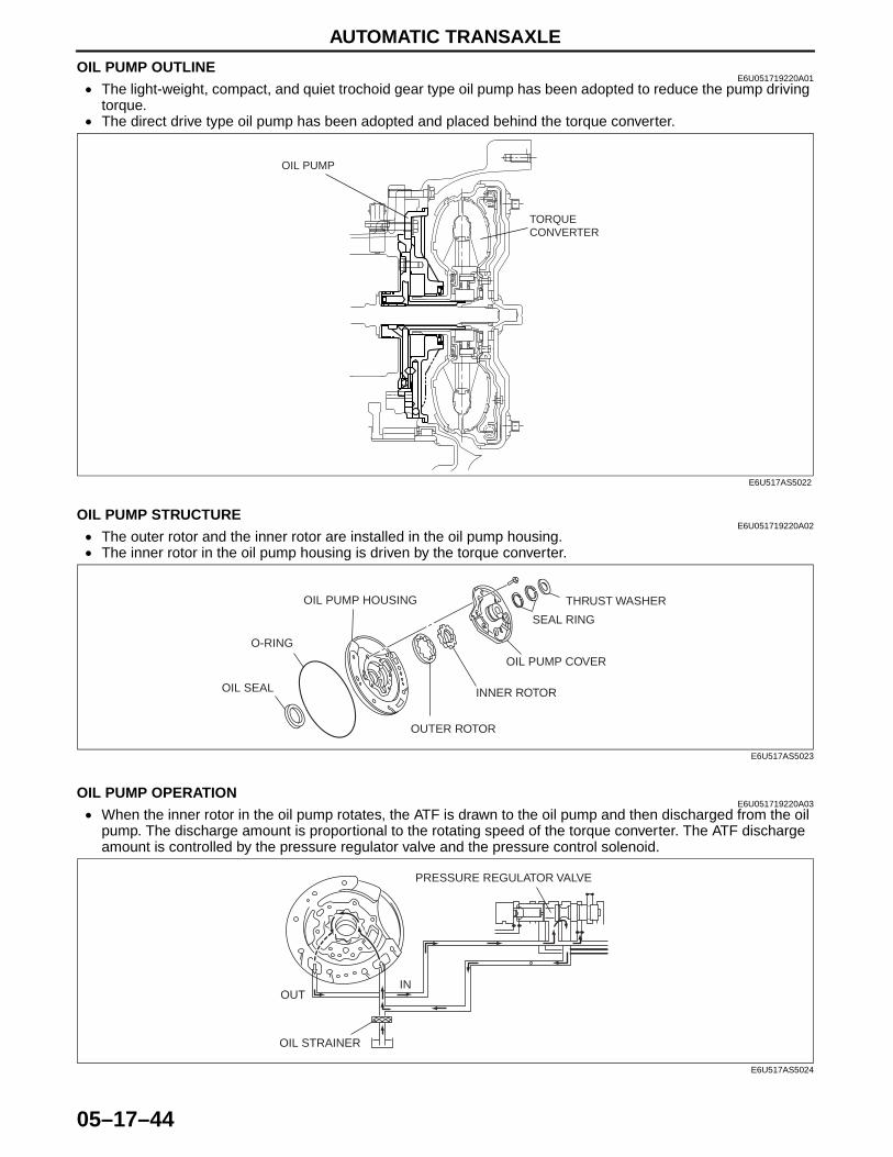
OIL PUMP OUTLINEE6U051719220A01
• The light-weight, compact, and quiet trochoid gear type oil pump has been adopted to reduce the pump driving torque.
• The direct drive type oil pump has been adopted and placed behind the torque converter.
End Of SieOIL PUMP STRUCTURE
E6U051719220A02• The outer rotor and the inner rotor are installed in the oil pump housing.• The inner rotor in the oil pump housing is driven by the torque converter.
End Of SieOIL PUMP OPERATION
E6U051719220A03• When the inner rotor in the oil pump rotates, the ATF is drawn to the oil pump and then discharged from the oil
pump. The discharge amount is proportional to the rotating speed of the torque converter. The ATF discharge amount is controlled by the pressure regulator valve and the pressure control solenoid.
End Of Sie
TORQUE CONVERTER
OIL PUMP
E6U517AS5022
OIL SEAL
O-RING
OIL PUMP HOUSING
OUTER ROTOR
INNER ROTOR
OIL PUMP COVER
SEAL RING
THRUST WASHER
E6U517AS5023
PRESSURE REGULATOR VALVE
OIL STRAINER
INOUT
E6U517AS5024

AUTOMATIC TRANSAXLE
05–17–45
05–17
FORWARD CLUTCH, 3-4 CLUTCH HYDRAULIC CIRCUIT OUTLINEE6U051719500A12
• By designing exclusive passages for the forward clutch and the 3-4 clutch in the transaxle case, via the oil pump and end cover the hydraulic pressure passages are shortened and control during clutch engagement is improved.
End Of Sie
OIL PUMP
FORWARD CLUTCH HYDRAULIC PASSAGE
FORWARD CLUTCH
END COVER
3-4 CLUTCH HYDRAULIC PASSAGE
3-4 CLUTCH
OIL PUMPEND COVER
3-4 CLUTCH HYDRAULIC PASSAGE
3-4 CLUTCH HYDRAULIC PASSAGE FORWARD CLUTCH
HYDRAULIC PASSAGE
E6U517YA6017
AUTOMATIC TRANSAXLE
05–17–46
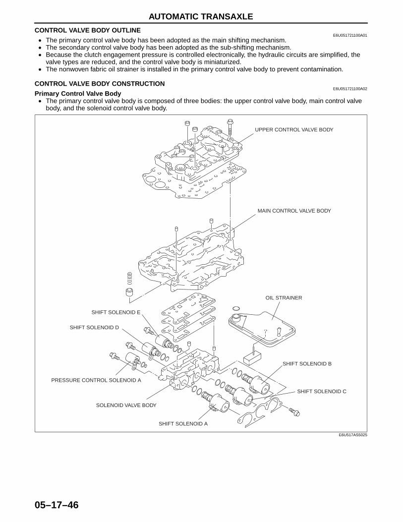
CONTROL VALVE BODY OUTLINEE6U051721100A01
• The primary control valve body has been adopted as the main shifting mechanism.• The secondary control valve body has been adopted as the sub-shifting mechanism.• Because the clutch engagement pressure is controlled electronically, the hydraulic circuits are simplified, the
valve types are reduced, and the control valve body is miniaturized.• The nonwoven fabric oil strainer is installed in the primary control valve body to prevent contamination.
End Of SieCONTROL VALVE BODY CONSTRUCTION
E6U051721100A02Primary Control Valve Body• The primary control valve body is composed of three bodies: the upper control valve body, main control valve
body, and the solenoid control valve body.
PRESSURE CONTROL SOLENOID A
SHIFT SOLENOID E
SHIFT SOLENOID D
SHIFT SOLENOID C
SHIFT SOLENOID B
SHIFT SOLENOID A
SOLENOID VALVE BODY
OIL STRAINER
MAIN CONTROL VALVE BODY
UPPER CONTROL VALVE BODY
E6U517AS5025
AUTOMATIC TRANSAXLE
05–17–47
05–17
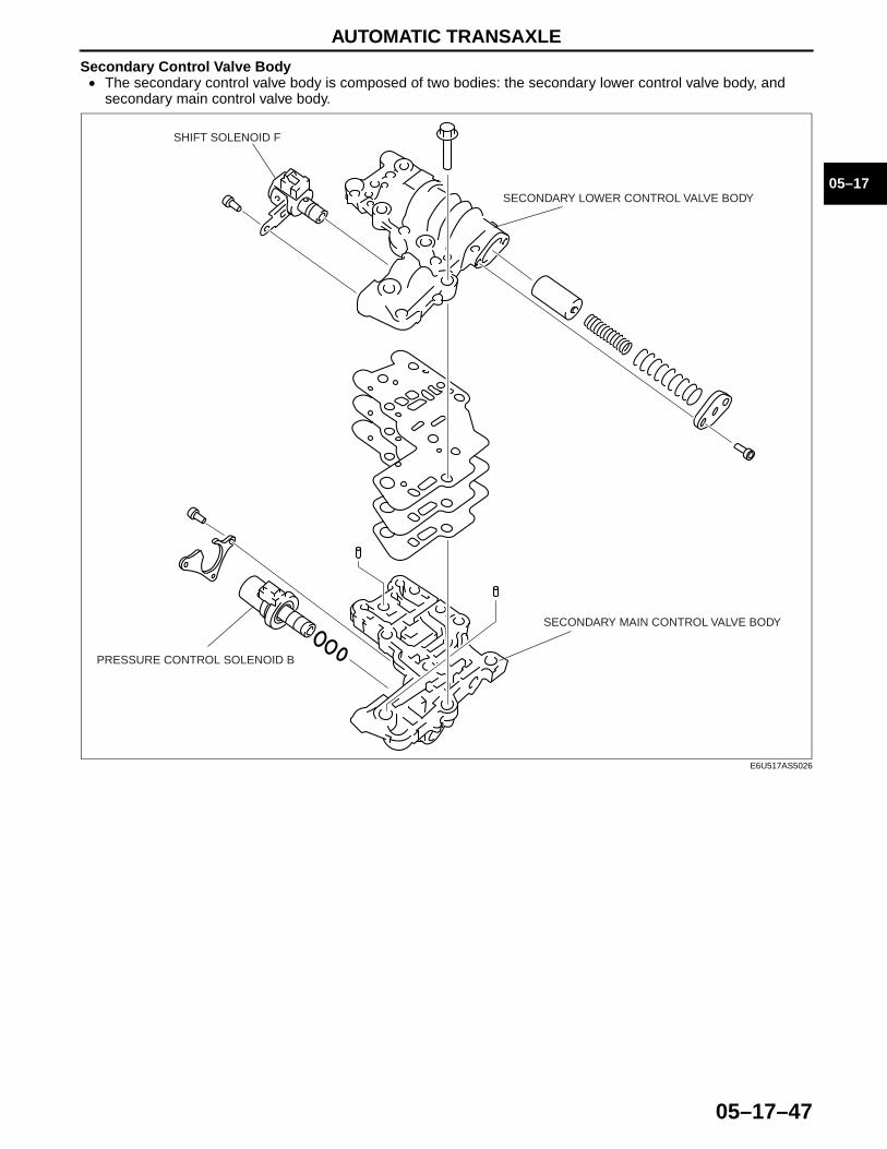
Secondary Control Valve Body• The secondary control valve body is composed of two bodies: the secondary lower control valve body, and
secondary main control valve body.
End Of Sie
SECONDARY MAIN CONTROL VALVE BODY
PRESSURE CONTROL SOLENOID B
SECONDARY LOWER CONTROL VALVE BODY
SHIFT SOLENOID F
E6U517AS5026

AUTOMATIC TRANSAXLE
05–17–48
SHIFT SOLENOID A, B AND C (DUTY-CYCLE TYPE) OUTLINEE6U051721101A01
• A clutch pressure direct control, which supplies the clutch pressure directly to each clutch and/or brake, has been adopted. A three-way duty-cycle type solenoids with excellent controllability have been adopted, to improve response.
End Of SieSHIFT SOLENOID A, B AND C (DUTY-CYCLE TYPE) FUNCTION
E6U051721101A02• The duty-cycle type shift solenoid adjusts the amount of output pressure according to the signal from the TCM,
and controls the pressure of each clutch.• The duty-cycle type shift solenoid, which switches
on/off at 50 Hz (20 ms cycle) and controls the output pressure, is adopted. By changing the on time ratio a cycle (0—100%), the solenoid adjusts the time ratio of the open (supply) and close (drain), and maintains the clutch pressure at the designated hydraulic pressure. As a result, the clutch pressure rises when the duty ratio (50 Hz on time ratio) is reduced, and falls when the duty ratio is raised.
End Of Sie
SHIFT SOLENOID A, B AND C (DUTY-CYCLE TYPE) OPERATIONE6U051721101A03
Open:When the electrical current does not flow, the supply port (line pressure) in the solenoid opens and is engaged with the output port (clutch pressure). As a result, hydraulic pressure is supplied to the hydraulic passage for the clutch pressure.
Close:When the electrical current flows, the supply port (line pressure) in the solenoid closes and the output port (clutch pressure) and the drain port are engaged to drain the clutch pressure.
End Of Sie
DRAIN SUPPLY PORT (LINE PRESSURE)
OUTPUT PORT (CLUTCH PRESSURE)
E6U517AS5042
DRAIN
SUPPLY PORT (LINE PRESSURE)
OUTPUT PORT (CLUTCH PRESSURE)
OUTPUT PORT (CLUTCH PRESSURE)ELECTRICAL CURRENT
FLOWS (CLOSE)
ELECTRICAL CURRENT DOES NOT FLOW (OPEN)
E6U517AS5043
AUTOMATIC TRANSAXLE
05–17–49
05–17
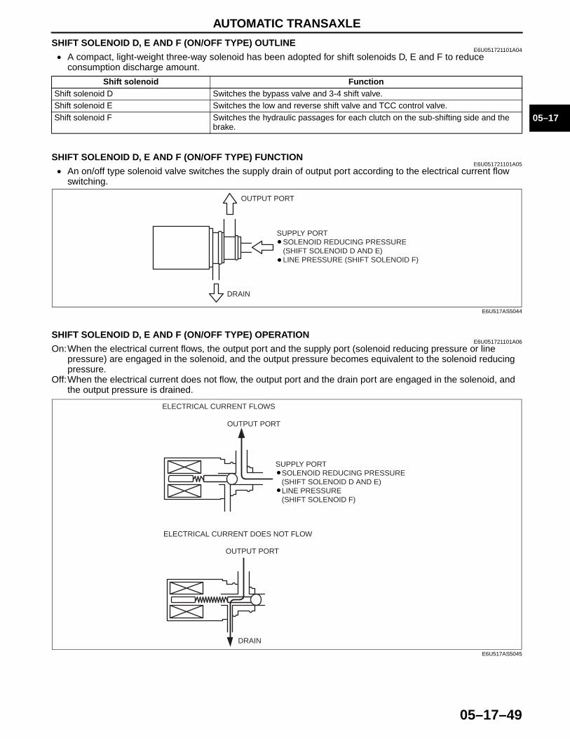
SHIFT SOLENOID D, E AND F (ON/OFF TYPE) OUTLINEE6U051721101A04
• A compact, light-weight three-way solenoid has been adopted for shift solenoids D, E and F to reduce consumption discharge amount.
End Of SieSHIFT SOLENOID D, E AND F (ON/OFF TYPE) FUNCTION
E6U051721101A05• An on/off type solenoid valve switches the supply drain of output port according to the electrical current flow
switching.
End Of SieSHIFT SOLENOID D, E AND F (ON/OFF TYPE) OPERATION
E6U051721101A06On:When the electrical current flows, the output port and the supply port (solenoid reducing pressure or line
pressure) are engaged in the solenoid, and the output pressure becomes equivalent to the solenoid reducing pressure.
Off:When the electrical current does not flow, the output port and the drain port are engaged in the solenoid, and the output pressure is drained.
End Of Sie
Shift solenoid FunctionShift solenoid D Switches the bypass valve and 3-4 shift valve.Shift solenoid E Switches the low and reverse shift valve and TCC control valve.Shift solenoid F Switches the hydraulic passages for each clutch on the sub-shifting side and the
brake.
DRAIN
OUTPUT PORT
SUPPLY PORT SOLENOID REDUCING PRESSURE (SHIFT SOLENOID D AND E) LINE PRESSURE (SHIFT SOLENOID F)
E6U517AS5044
DRAIN
OUTPUT PORT
OUTPUT PORT
ELECTRICAL CURRENT DOES NOT FLOW
ELECTRICAL CURRENT FLOWS
SUPPLY PORT SOLENOID REDUCING PRESSURE (SHIFT SOLENOID D AND E) LINE PRESSURE (SHIFT SOLENOID F)
E6U517AS5045
AUTOMATIC TRANSAXLE
05–17–50
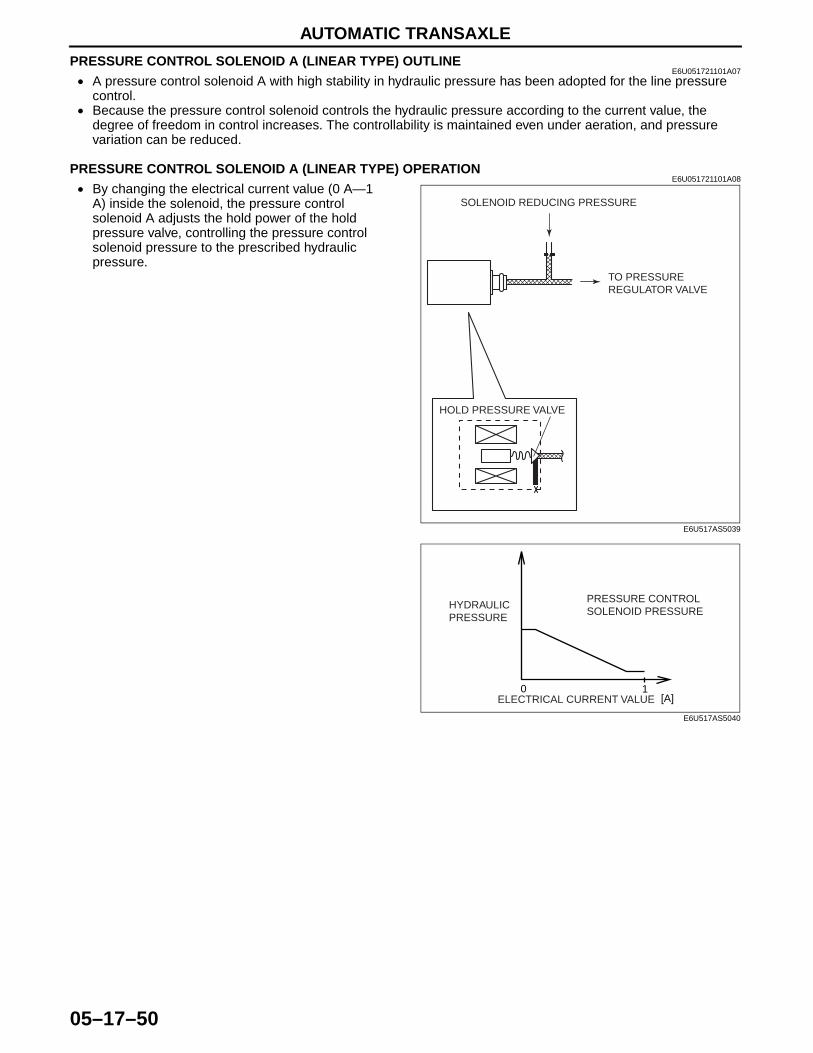
PRESSURE CONTROL SOLENOID A (LINEAR TYPE) OUTLINEE6U051721101A07
• A pressure control solenoid A with high stability in hydraulic pressure has been adopted for the line pressure control.
• Because the pressure control solenoid controls the hydraulic pressure according to the current value, the degree of freedom in control increases. The controllability is maintained even under aeration, and pressure variation can be reduced.
End Of SiePRESSURE CONTROL SOLENOID A (LINEAR TYPE) OPERATION
E6U051721101A08• By changing the electrical current value (0 A—1
A) inside the solenoid, the pressure control solenoid A adjusts the hold power of the hold pressure valve, controlling the pressure control solenoid pressure to the prescribed hydraulic pressure.
End Of Sie
HOLD PRESSURE VALVE
TO PRESSURE REGULATOR VALVE
SOLENOID REDUCING PRESSURE
E6U517AS5039
[A]0 1
PRESSURE CONTROL SOLENOID PRESSURE
ELECTRICAL CURRENT VALUE
HYDRAULIC PRESSURE
E6U517AS5040
AUTOMATIC TRANSAXLE
05–17–51
05–17
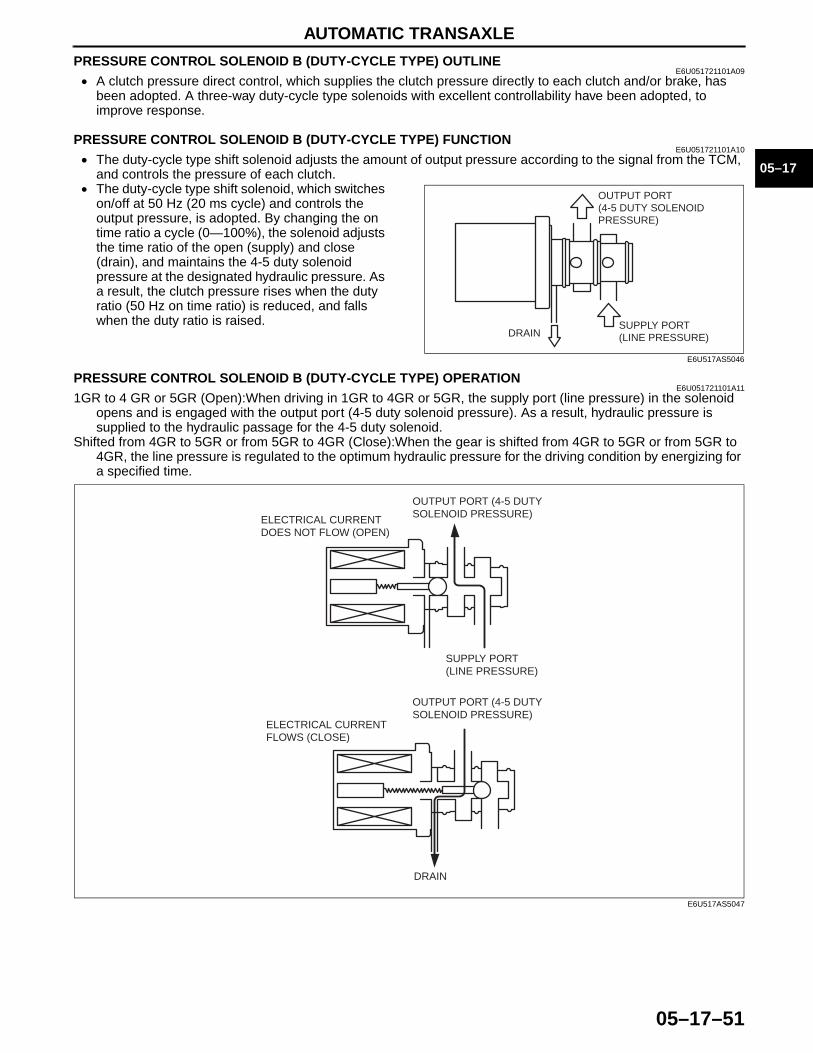
PRESSURE CONTROL SOLENOID B (DUTY-CYCLE TYPE) OUTLINEE6U051721101A09
• A clutch pressure direct control, which supplies the clutch pressure directly to each clutch and/or brake, has been adopted. A three-way duty-cycle type solenoids with excellent controllability have been adopted, to improve response.
End Of SiePRESSURE CONTROL SOLENOID B (DUTY-CYCLE TYPE) FUNCTION
E6U051721101A10• The duty-cycle type shift solenoid adjusts the amount of output pressure according to the signal from the TCM,
and controls the pressure of each clutch.• The duty-cycle type shift solenoid, which switches
on/off at 50 Hz (20 ms cycle) and controls the output pressure, is adopted. By changing the on time ratio a cycle (0—100%), the solenoid adjusts the time ratio of the open (supply) and close (drain), and maintains the 4-5 duty solenoid pressure at the designated hydraulic pressure. As a result, the clutch pressure rises when the duty ratio (50 Hz on time ratio) is reduced, and falls when the duty ratio is raised.
End Of Sie
PRESSURE CONTROL SOLENOID B (DUTY-CYCLE TYPE) OPERATIONE6U051721101A11
1GR to 4 GR or 5GR (Open):When driving in 1GR to 4GR or 5GR, the supply port (line pressure) in the solenoid opens and is engaged with the output port (4-5 duty solenoid pressure). As a result, hydraulic pressure is supplied to the hydraulic passage for the 4-5 duty solenoid.
Shifted from 4GR to 5GR or from 5GR to 4GR (Close):When the gear is shifted from 4GR to 5GR or from 5GR to 4GR, the line pressure is regulated to the optimum hydraulic pressure for the driving condition by energizing for a specified time.
End Of Sie
SUPPLY PORT (LINE PRESSURE)DRAIN
OUTPUT PORT(4-5 DUTY SOLENOID PRESSURE)
E6U517AS5046
DRAIN
SUPPLY PORT (LINE PRESSURE)
OUTPUT PORT (4-5 DUTY SOLENOID PRESSURE)
OUTPUT PORT (4-5 DUTY SOLENOID PRESSURE)
ELECTRICAL CURRENT FLOWS (CLOSE)
ELECTRICAL CURRENT DOES NOT FLOW (OPEN)
E6U517AS5047

SERVICE

00GENERAL INFORMATION
00–00–1
SECTION00–00
Toc of SCTGENERAL INFORMATION . . . .00-00
Toc of SCT
00–00 GENERAL INFORMATIONHOW TO USE THIS MANUAL . . . . . . . . . 00–00–2
Range of Topics . . . . . . . . . . . . . . . . . . 00–00–2Service Procedure . . . . . . . . . . . . . . . . 00–00–2Symbols . . . . . . . . . . . . . . . . . . . . . . . . 00–00–4Advisory Messages . . . . . . . . . . . . . . . . 00–00–4
UNITS . . . . . . . . . . . . . . . . . . . . . . . . . . . . 00–00–5Conversion to SI Units
(Système International d'Unités) . . . . . 00–00–5Rounding Off . . . . . . . . . . . . . . . . . . . . . 00–00–5Upper and Lower Limits . . . . . . . . . . . . 00–00–5
FUNDAMENTAL PROCEDURES. . . . . . . 00–00–6Preparation of Tools and Measuring
Equipment . . . . . . . . . . . . . . . . . . . . . . 00–00–6Special Service Tools . . . . . . . . . . . . . . 00–00–6Disassembly . . . . . . . . . . . . . . . . . . . . . 00–00–6
Inspection During Removal, Disassembly . . . . . . . . . . . . . . . . . . . . 00–00–6
Arrangement of Parts . . . . . . . . . . . . . . 00–00–7Cleaning of Parts . . . . . . . . . . . . . . . . . 00–00–7Reassembly . . . . . . . . . . . . . . . . . . . . . 00–00–7Adjustment . . . . . . . . . . . . . . . . . . . . . . 00–00–8Rubber Parts and Tubing . . . . . . . . . . . 00–00–8Hose Clamps . . . . . . . . . . . . . . . . . . . . 00–00–8Torque Formulas . . . . . . . . . . . . . . . . . 00–00–8Vise . . . . . . . . . . . . . . . . . . . . . . . . . . . 00–00–9
ELECTRICAL SYSTEM. . . . . . . . . . . . . . 00–00–9Connectors . . . . . . . . . . . . . . . . . . . . . . 00–00–9
SAE STANDARDS. . . . . . . . . . . . . . . . . . 00–00–10ABBREVIATIONS . . . . . . . . . . . . . . . . . . 00–00–11
End of Toc
GENERAL INFORMATION
00–00–2
HOW TO USE THIS MANUALE6U000000000A01
Range of Topics• This manual contains procedures for performing all required service operations. The procedures are divided
into the following five basic operations: — Removal/Installation— Disassembly/Assembly— Replacement— Inspection— Adjustment
• Simple operations which can be performed easily just by looking at the vehicle (i.e., removal/installation of parts, jacking, vehicle lifting, cleaning of parts, and visual inspection) have been omitted.
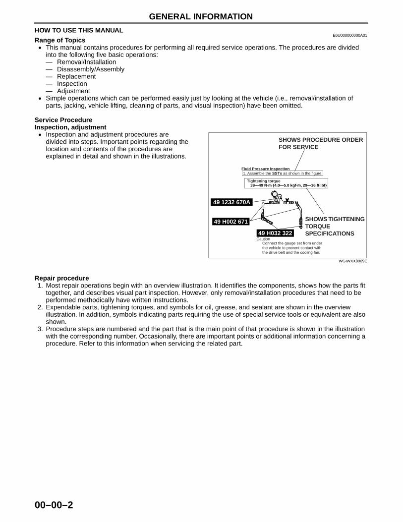
Service ProcedureInspection, adjustment• Inspection and adjustment procedures are
divided into steps. Important points regarding the location and contents of the procedures are explained in detail and shown in the illustrations.
Repair procedure1. Most repair operations begin with an overview illustration. It identifies the components, shows how the parts fit
together, and describes visual part inspection. However, only removal/installation procedures that need to be performed methodically have written instructions.
2. Expendable parts, tightening torques, and symbols for oil, grease, and sealant are shown in the overview illustration. In addition, symbols indicating parts requiring the use of special service tools or equivalent are also shown.
3. Procedure steps are numbered and the part that is the main point of that procedure is shown in the illustration with the corresponding number. Occasionally, there are important points or additional information concerning a procedure. Refer to this information when servicing the related part.
49 H002 671
49 H032 322
49 1232 670A
SHOWS PROCEDURE ORDERFOR SERVICE
Fluid Pressure Inspection1. Assemble the SSTs as shown in the figure.
Tightening torque
SHOWS TIGHTENINGTORQUESPECIFICATIONS
CautionConnect the gauge set from underthe vehicle to prevent contact withthe drive belt and the cooling fan.
39—49 N·m {4.0—5.0 kgf·m, 29—36 ft·lbf}
WGIWXX0009E
GENERAL INFORMATION
00–00–3
00–00
GR
EA
SE
GR
EA
SE
GR
EA
SE
GR
EA
SE
SHOWS NON-REUSEABLE PARTS
SHOWS DETAILS
KNUCKLE
UPPER TRAILING LINK
LOWER TRAILING LINK
SST
SST
SST
SST
R
R
R
R
9
2
1
4
53
6
1
2
8
7
12
10
11
N·m {kgf·m, ft·lbf}
118—156 {12.0—16.0, 87—115}94—116 {9.5—11.9, 69—86}
43—56 {4.3—5.8, 32—41}
49 T028 30449 T028 305
49 T028 303
Procedure
LOWER TRAILING LINK, UPPER TRAILING LINK REMOVAL/INSTALLATION1. Jack up the rear of the vehicle and support it with safety stands.2. Remove the undercover. (See 01-10-4 Undercover Removal)3. Remove in the order indicated in the table.4. Install in the reverse order of removal.5. Inspect the rear wheel alignment and adjust it if necessary.
1 Split pin2 Nut
3 Lower trailing link ball joint
4
(See 02-14-5 Lower Trailing Link Ball Joint Removal Note)
Bolt5 Lower trailing link 6 Dust boot (lower trailing link)
7 Split pin8 Nut9 Upper trailing link ball joint
(See 02-14-5 Upper Trailing Link Ball Joint Removal Note)10 Nut11 Upper trailing link12 Dust boot (upper trailing link)
Lower Trailing Link Ball Joint, Upper Trailing LinkBall Joint Removal Note
Remove the ball joint using the SSTs.
— 44—60 {4.4—6.2, 32—44}
"Removal/Installation" Portion
"Inspection After Installation" Portion
INSTALL THE PARTS BY PERFORMING STEPS 1—3 IN REVERSE ORDER
SHOWS PROCEDURE ORDER FOR SERVICE
SHOWS TIGHTENING TORQUE SPECIFICATIONS
SHOWS SERVICE ITEM (S)
INDICATES ANY RELEVANT REFERENCES WHICH NEED TO BE FOLLOWED DURING INSTALLATION
SHOWS SPECIAL SERVICE TOOL (SST) FOR SERVICE OPERATION
SHOWS APPLICATION POINTS OF GREASE, ETC.
SHOWS TIGHTENING TORQUE UNITS
SHOWS SPECIAL SERVICE TOOL (SST) NO.
SHOWS REFERRAL NOTES FOR SERVICE
SHOWS THERE ARE REFERRAL NOTES FOR SERVICE
BHE0000W104
GENERAL INFORMATION
00–00–4
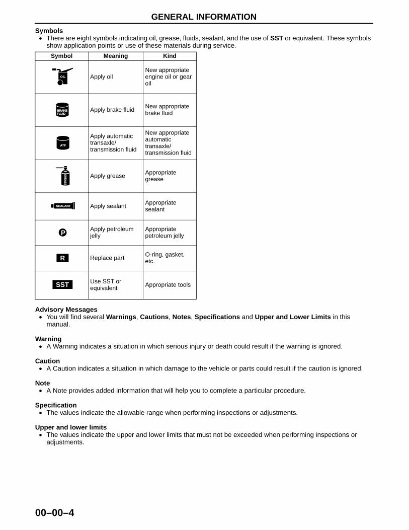
Symbols• There are eight symbols indicating oil, grease, fluids, sealant, and the use of SST or equivalent. These symbols
show application points or use of these materials during service.
Advisory Messages• You will find several Warnings, Cautions, Notes, Specifications and Upper and Lower Limits in this
manual.
Warning• A Warning indicates a situation in which serious injury or death could result if the warning is ignored.
Caution• A Caution indicates a situation in which damage to the vehicle or parts could result if the caution is ignored.
Note• A Note provides added information that will help you to complete a particular procedure.
Specification• The values indicate the allowable range when performing inspections or adjustments.
Upper and lower limits• The values indicate the upper and lower limits that must not be exceeded when performing inspections or
adjustments.End Of Sie
Symbol Meaning Kind
Apply oilNew appropriate engine oil or gear oil
Apply brake fluid New appropriate brake fluid
Apply automatic transaxle/transmission fluid
New appropriate automatic transaxle/transmission fluid
Apply grease Appropriate grease
Apply sealant Appropriate sealant
Apply petroleum jelly
Appropriate petroleum jelly
Replace part O-ring, gasket, etc.
Use SST or equivalent Appropriate tools
OIL
BRAKEFLUID
AATFTF
GR
EA
SE
GR
EA
SE
SEALANT
P
R
SST
GENERAL INFORMATION
00–00–5
00–00
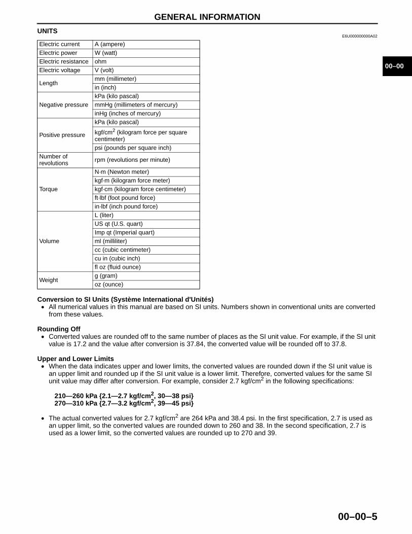
UNITSE6U000000000A02
Conversion to SI Units (Système International d'Unités)• All numerical values in this manual are based on SI units. Numbers shown in conventional units are converted
from these values.
Rounding Off• Converted values are rounded off to the same number of places as the SI unit value. For example, if the SI unit
value is 17.2 and the value after conversion is 37.84, the converted value will be rounded off to 37.8.
Upper and Lower Limits• When the data indicates upper and lower limits, the converted values are rounded down if the SI unit value is
an upper limit and rounded up if the SI unit value is a lower limit. Therefore, converted values for the same SI unit value may differ after conversion. For example, consider 2.7 kgf/cm2 in the following specifications:
210—260 kPa {2.1—2.7 kgf/cm2, 30—38 psi}270—310 kPa {2.7—3.2 kgf/cm2, 39—45 psi}
• The actual converted values for 2.7 kgf/cm2 are 264 kPa and 38.4 psi. In the first specification, 2.7 is used as an upper limit, so the converted values are rounded down to 260 and 38. In the second specification, 2.7 is used as a lower limit, so the converted values are rounded up to 270 and 39.
End Of Sie
Electric current A (ampere)Electric power W (watt)Electric resistance ohmElectric voltage V (volt)
Lengthmm (millimeter)in (inch)
Negative pressurekPa (kilo pascal)mmHg (millimeters of mercury)inHg (inches of mercury)
Positive pressure
kPa (kilo pascal)
kgf/cm2 (kilogram force per square centimeter)psi (pounds per square inch)
Number of revolutions rpm (revolutions per minute)
Torque
N·m (Newton meter)kgf·m (kilogram force meter)kgf·cm (kilogram force centimeter)ft·lbf (foot pound force)in·lbf (inch pound force)
Volume
L (liter)US qt (U.S. quart)Imp qt (Imperial quart)ml (milliliter)cc (cubic centimeter)cu in (cubic inch)fl oz (fluid ounce)
Weightg (gram)oz (ounce)

GENERAL INFORMATION
00–00–6
FUNDAMENTAL PROCEDURESE6U000000000A03
Preparation of Tools and Measuring Equipment• Be sure that all necessary tools and measuring
equipment are available before starting any work.
Special Service Tools• Use special service tools or equivalent when they
are required.
Disassembly• If the disassembly procedure is complex,
requiring many parts to be disassembled, all parts should be marked in a place that will not affect their performance or external appearance and identified so that reassembly can be performed easily and efficiently.
Inspection During Removal, Disassembly• When removed, each part should be carefully
inspected for malfunction, deformation, damage and other problems.
CHU0014W003
49 SE01 310
WGIWXX0024E
WGIWXX0027E
WGIWXX0028E
GENERAL INFORMATION
00–00–7
00–00
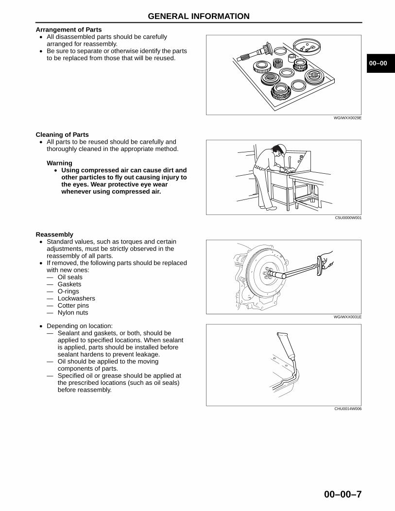
Arrangement of Parts• All disassembled parts should be carefully
arranged for reassembly.• Be sure to separate or otherwise identify the parts
to be replaced from those that will be reused.
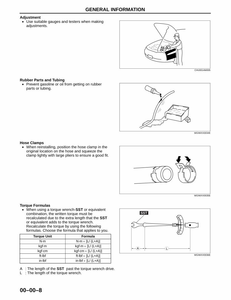
Cleaning of Parts• All parts to be reused should be carefully and
thoroughly cleaned in the appropriate method.
Warning• Using compressed air can cause dirt and
other particles to fly out causing injury to the eyes. Wear protective eye wear whenever using compressed air.
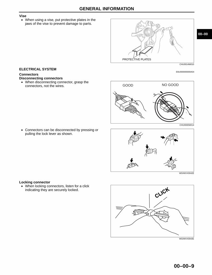
Reassembly• Standard values, such as torques and certain
adjustments, must be strictly observed in the reassembly of all parts.
• If removed, the following parts should be replaced with new ones: — Oil seals— Gaskets— O-rings— Lockwashers— Cotter pins— Nylon nuts
• Depending on location: — Sealant and gaskets, or both, should be
applied to specified locations. When sealant is applied, parts should be installed before sealant hardens to prevent leakage.
— Oil should be applied to the moving components of parts.
— Specified oil or grease should be applied at the prescribed locations (such as oil seals) before reassembly.
WGIWXX0029E
C5U0000W001
WGIWXX0031E
CHU0014W006
GENERAL INFORMATION
00–00–8
Adjustment• Use suitable gauges and testers when making
adjustments.
Rubber Parts and Tubing• Prevent gasoline or oil from getting on rubber
parts or tubing.
Hose Clamps• When reinstalling, position the hose clamp in the
original location on the hose and squeeze the clamp lightly with large pliers to ensure a good fit.
Torque Formulas• When using a torque wrench-SST or equivalent
combination, the written torque must be recalculated due to the extra length that the SST or equivalent adds to the torque wrench. Recalculate the torque by using the following formulas. Choose the formula that applies to you.
A : The length of the SST past the torque wrench drive.L : The length of the torque wrench.
CHU0014W005
WGIWXX0034E
WGIWXX0035E
Torque Unit FormulaN·m N·m × [L/ (L+A)]
kgf·m kgf·m × [L/ (L+A)]kgf·cm kgf·cm × [L/ (L+A)]ft·lbf ft·lbf × [L/ (L+A)]in·lbf in·lbf × [L/ (L+A)]
01
12
2
33
SST
A L
WGIWXX0036E
GENERAL INFORMATION
00–00–9
00–00
Vise• When using a vise, put protective plates in the
jaws of the vise to prevent damage to parts.End Of Sie
ELECTRICAL SYSTEME6U000000000A04
ConnectorsDisconnecting connectors• When disconnecting connector, grasp the
connectors, not the wires.
• Connectors can be disconnected by pressing or pulling the lock lever as shown.
Locking connector• When locking connectors, listen for a click
indicating they are securely locked.
PROTECTIVE PLATES
CHU0014W010
GOOD NO GOOD
CHU0000W014
WGIWXX0042E
WGIWXX0043E
GENERAL INFORMATION
00–00–10
Inspection• When a tester is used to inspect for continuity or
measuring voltage, insert the tester probe from the wiring harness side.
• Inspect the terminals of waterproof connectors from the connector side since they cannot be accessed from the wiring harness side.
Caution• To prevent damage to the terminal, wrap
a thin wire around the tester probe before inserting into terminal.
End Of Sie
SAE STANDARDSE6U000000000A07
• In accordance with new regulations, SAE (Society of Automotive Engineers) standard names and abbreviations are now used in this manual. The table below lists the names and abbreviations that have been used in Mazda manuals up to now and their SAE equivalents.
GOOD NO GOOD
CHU0000W011
GOOD NO GOOD
CHU0000W012
SAE StandardRemark
SAE StandardRemark
Abbreviation Name Abbreviation NameAP Accelerator Pedal MAP Manifold Absolute PressureAPP Accelerator Pedal Position MAF Mass Air FlowACL Air Cleaner MAF sensor Mass Air Flow SensorA/C Air Conditioning MFL Multiport Fuel InjectionA/F Air Fuel Ratio OBD On-board Diagnostic SystemBARO Barometric Pressure OL Open LoopB+ Battery Positive Voltage OC Oxidation Catalytic ConverterCMP sensor Camshaft Position Sensor O2S Oxygen SensorLOAD Calculated Load Value PNP Park/Neutral PositionCAC Charge Air Cooler PID Parameter IdentificationCLS Closed Loop System PSP Power Steering PressureCTP Closed Throttle Position PCM Powertrain Control Module #3CPP Clutch Pedal Position
PAIR Pulsed Secondary Air Injection Pulsed injectionCIS Continuous Fuel Injection System
CKP sensor Crankshaft Position SensorAIR Secondary Air Injection
Injection with air pump
DLC Data Link ConnectorDTM Diagnostic Test Mode #1DTC Diagnostic Test Code(s) SAPV Secondary Air Pulse ValveDI Distributor Ignition
SFI Sequential Multiport Fuel InjectionDLI Distributorless Ignition
EI Electronic Ignition #2 3GR Third GearECT Engine Coolant Temperature TWC Three Way Catalytic ConverterEM Engine Modification TB Throttle BodyEVAP Evaporative Emission TP Throttle PositionEGR Exhaust Gas Recirculation TP sensor Throttle Position SensorFC Fan Control TCC Torque Converter Clutch
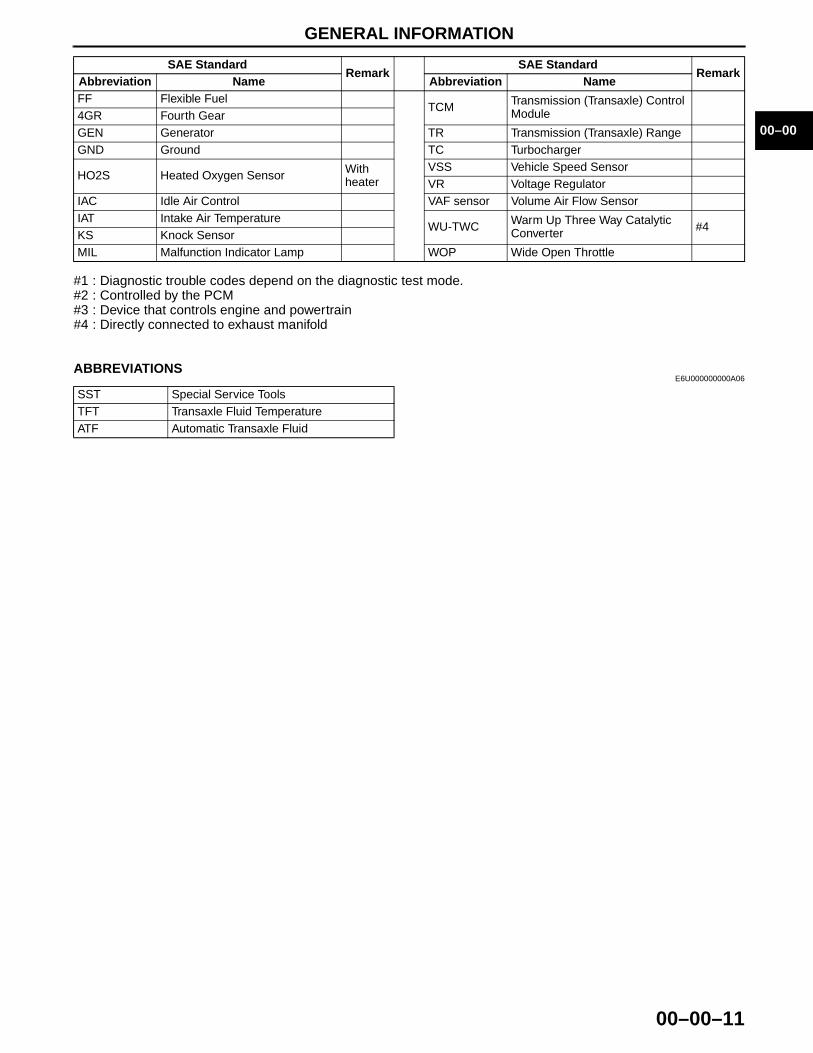
GENERAL INFORMATION
00–00–11
00–00
#1 : Diagnostic trouble codes depend on the diagnostic test mode.#2 : Controlled by the PCM#3 : Device that controls engine and powertrain#4 : Directly connected to exhaust manifold
End Of SieABBREVIATIONS
E6U000000000A06
End Of Sie
FF Flexible FuelTCM Transmission (Transaxle) Control
Module4GR Fourth GearGEN Generator TR Transmission (Transaxle) RangeGND Ground TC Turbocharger
HO2S Heated Oxygen Sensor With heater
VSS Vehicle Speed SensorVR Voltage Regulator
IAC Idle Air Control VAF sensor Volume Air Flow SensorIAT Intake Air Temperature
WU-TWC Warm Up Three Way Catalytic Converter #4
KS Knock SensorMIL Malfunction Indicator Lamp WOP Wide Open Throttle
SAE StandardRemark
SAE StandardRemark
Abbreviation Name Abbreviation Name
SST Special Service ToolsTFT Transaxle Fluid TemperatureATF Automatic Transaxle Fluid


05–17–1
05TRANSMISSION/TRANSAXLESECTION
05–17
Toc of SCTAUTOMATIC TRANSAXLE. . . .05-17TECHNICAL DATA . . . . . . . . . .05-50
SERVICE TOOLS . . . . . . . . . . . 05-60
Toc of SCT
05–17 AUTOMATIC TRANSAXLEAUTOMATIC TRANSAXLE
CLEANING . . . . . . . . . . . . . . . . . . . . . . . 05–17–2Cleaning Notes . . . . . . . . . . . . . . . . . . . 05–17–2
AUTOMATIC TRANSAXLEDISASSEMBLY. . . . . . . . . . . . . . . . . . . . 05–17–2
Precaution . . . . . . . . . . . . . . . . . . . . . . . 05–17–2Disassembly . . . . . . . . . . . . . . . . . . . . . 05–17–3
ACCUMULATORSDISASSEMBLY/ASSEMBLY . . . . . . . . . 05–17–17
Assembly Procedure . . . . . . . . . . . . . . . 05–17–17OIL PUMP
DISASSEMBLY/ASSEMBLY . . . . . . . . . 05–17–18Oil Pump Cover Disassembly Note . . . . 05–17–18Inner Rotor, Outer Rotor
Disassembly Note . . . . . . . . . . . . . . . . 05–17–19Assembly Procedure . . . . . . . . . . . . . . . 05–17–19
FORWARD CLUTCHDISASSEMBLY/ASSEMBLY . . . . . . . . . 05–17–21
Snap Ring Disassembly Note . . . . . . . . 05–17–21Forward Clutch Piston
Disassembly Note . . . . . . . . . . . . . . . . 05–17–22Assembly Procedure . . . . . . . . . . . . . . . 05–17–22
CLUTCH COMPONENTDISASSEMBLY/ASSEMBLY . . . . . . . . . 05–17–25
Snap Ring (3–4 clutch) Disassembly Note . . . . . . . . . . . . . . . . 05–17–26
3–4 Clutch Piston Disassembly Note . . 05–17–26Snap Ring (Reverse clutch)
Disassembly Note . . . . . . . . . . . . . . . . 05–17–27Reverse Piston Disassembly Note . . . . 05–17–27Assembly Procedure . . . . . . . . . . . . . . . 05–17–27
FRONT INTERNAL GEAR ONE-WAYCLUTCH NO.1 COMPONENT DISASSEMBLY/ASSEMBLY . . . . . . . . . 05–17–34
One-Way Clutch Retainer Disassembly Note . . . . . . . . . . . . . . . . 05–17–34
Assembly Procedure . . . . . . . . . . . . . . . 05–17–34BAND SERVO
DISASSEMBLY/ASSEMBLY . . . . . . . . . 05–17–35Assembly Procedure . . . . . . . . . . . . . . . 05–17–36
LOW AND REVERSE BRAKE ANDONE-WAY CLUTCH INNER RACEDISASSEMBLY/ASSEMBLY . . . . . . . . . 05–17–37
Snap Ring Disassembly Note . . . . . . . . 05–17–37Low and Reverse Brake Piston
Disassembly Note . . . . . . . . . . . . . . . . 05–17–38Assembly Procedure . . . . . . . . . . . . . . . 05–17–38
DIRECT CLUTCHDISASSEMBLY/ASSEMBLY . . . . . . . . . 05–17–41
Needle Bearing Disassembly Note. . . . 05–17–41Snap Ring (Direct clutch)
Disassembly Note . . . . . . . . . . . . . . . 05–17–42Direct Clutch Piston
Disassembly Note . . . . . . . . . . . . . . . 05–17–42Assembly Procedure . . . . . . . . . . . . . . 05–17–42
REDUCTION BRAKEDISASSEMBLY/ASSEMBLY . . . . . . . . . 05–17–46
Snap Ring Disassembly Note. . . . . . . . 05–17–46Reduction Brake Piston
Disassembly Note . . . . . . . . . . . . . . . 05–17–47Assembly Procedure . . . . . . . . . . . . . . 05–17–47
PARKING MECHANISM DISASSEMBLY/ASSEMBLY . . . . . . . . . 05–17–50
Assembly Procedure . . . . . . . . . . . . . . 05–17–51SECONDARY GEAR AND OUTPUT GEAR
DISASSEMBLY/ASSEMBLY . . . . . . . . . 05–17–52Lock nut Disassembly Note . . . . . . . . . 05–17–52Output gear And Inner Race
Disassembly Note . . . . . . . . . . . . . . . 05–17–53Output gear And Inner Race
Assembly Note . . . . . . . . . . . . . . . . . . 05–17–53Lock nut Assembly Note. . . . . . . . . . . . 05–17–53
PRIMARY GEARDISASSEMBLY/ASSEMBLY . . . . . . . . . 05–17–54
Bearing Disassembly Note . . . . . . . . . . 05–17–54Bearing Assembly Note . . . . . . . . . . . . 05–17–54
PRIMARY CONTROL VALVE BODY DISASSEMBLY/ASSEMBLY . . . . . . . . . 05–17–55
Primary Control Valve BodyDisassembly . . . . . . . . . . . . . . . . . . . . 05–17–55
Disassembly procedure . . . . . . . . . . . . 05–17–56Upper Control Valve Body
Disassembly/Assembly . . . . . . . . . . . 05–17–59Assembly procedure. . . . . . . . . . . . . . . 05–17–60Main Control Valve Body
Disassembly/Assembly . . . . . . . . . . . 05–17–60Assembly procedure. . . . . . . . . . . . . . . 05–17–61Primary Control Valve Body
Assembly . . . . . . . . . . . . . . . . . . . . . . 05–17–63Assembly procedure. . . . . . . . . . . . . . . 05–17–64
SECONDARY CONTROL VALVE BODY DISASSEMBLY/ASSEMBLY . . . . . . . . . 05–17–66
Secondary Control Valve Body Disassembly . . . . . . . . . . . . . . . . . . . . 05–17–66
Disassembly procedure . . . . . . . . . . . . 05–17–68
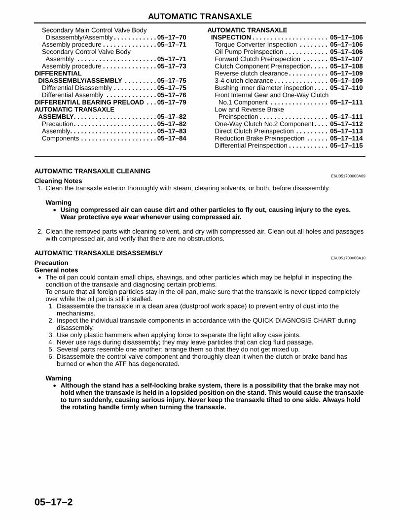
AUTOMATIC TRANSAXLE
05–17–2
Secondary Main Control Valve BodyDisassembly/Assembly . . . . . . . . . . . . 05–17–70
Assembly procedure . . . . . . . . . . . . . . . 05–17–71Secondary Control Valve Body
Assembly . . . . . . . . . . . . . . . . . . . . . . 05–17–71Assembly procedure . . . . . . . . . . . . . . . 05–17–73
DIFFERENTIALDISASSEMBLY/ASSEMBLY . . . . . . . . . 05–17–75
Differential Disassembly . . . . . . . . . . . . 05–17–75Differential Assembly . . . . . . . . . . . . . . 05–17–76
DIFFERENTIAL BEARING PRELOAD . . . 05–17–79AUTOMATIC TRANSAXLE
ASSEMBLY. . . . . . . . . . . . . . . . . . . . . . . 05–17–82Precaution . . . . . . . . . . . . . . . . . . . . . . . 05–17–82Assembly. . . . . . . . . . . . . . . . . . . . . . . . 05–17–83Components . . . . . . . . . . . . . . . . . . . . . 05–17–84
AUTOMATIC TRANSAXLEINSPECTION . . . . . . . . . . . . . . . . . . . . . 05–17–106
Torque Converter Inspection . . . . . . . . 05–17–106Oil Pump Preinspection . . . . . . . . . . . . 05–17–106Forward Clutch Preinspection . . . . . . . 05–17–107Clutch Component Preinspection. . . . . 05–17–108Reverse clutch clearance . . . . . . . . . . . 05–17–1093-4 clutch clearance . . . . . . . . . . . . . . . 05–17–109Bushing inner diameter inspection . . . . 05–17–110Front Internal Gear and One-Way Clutch
No.1 Component . . . . . . . . . . . . . . . . 05–17–111Low and Reverse Brake
Preinspection . . . . . . . . . . . . . . . . . . . 05–17–111One-Way Clutch No.2 Component . . . . 05–17–112Direct Clutch Preinspection . . . . . . . . . 05–17–113Reduction Brake Preinspection . . . . . . 05–17–114Differential Preinspection . . . . . . . . . . . 05–17–115
End of Toc
AUTOMATIC TRANSAXLE CLEANINGE6U051700000A09
Cleaning Notes1. Clean the transaxle exterior thoroughly with steam, cleaning solvents, or both, before disassembly.
Warning• Using compressed air can cause dirt and other particles to fly out, causing injury to the eyes.
Wear protective eye wear whenever using compressed air.
2. Clean the removed parts with cleaning solvent, and dry with compressed air. Clean out all holes and passages with compressed air, and verify that there are no obstructions.
End Of SieAUTOMATIC TRANSAXLE DISASSEMBLY
E6U051700000A10PrecautionGeneral notes• The oil pan could contain small chips, shavings, and other particles which may be helpful in inspecting the
condition of the transaxle and diagnosing certain problems.To ensure that all foreign particles stay in the oil pan, make sure that the transaxle is never tipped completely over while the oil pan is still installed.1. Disassemble the transaxle in a clean area (dustproof work space) to prevent entry of dust into the
mechanisms.2. Inspect the individual transaxle components in accordance with the QUICK DIAGNOSIS CHART during
disassembly.3. Use only plastic hammers when applying force to separate the light alloy case joints.4. Never use rags during disassembly; they may leave particles that can clog fluid passage.5. Several parts resemble one another; arrange them so that they do not get mixed up.6. Disassemble the control valve component and thoroughly clean it when the clutch or brake band has
burned or when the ATF has degenerated.
Warning• Although the stand has a self-locking brake system, there is a possibility that the brake may not
hold when the transaxle is held in a lopsided position on the stand. This would cause the transaxle to turn suddenly, causing serious injury. Never keep the transaxle tilted to one side. Always hold the rotating handle firmly when turning the transaxle.
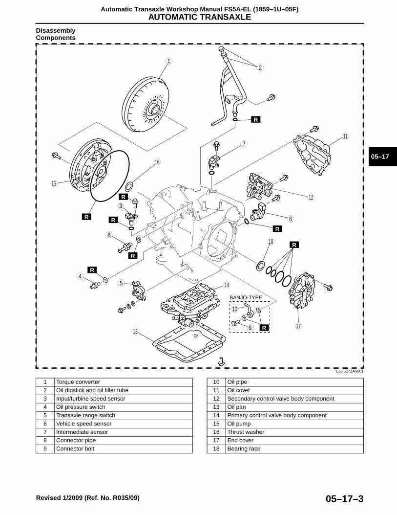
AUTOMATIC TRANSAXLE
05–17–3
05–17
Automatic Transaxle Workshop Manual FS5A-EL (1859–1U–05F)
Revised 1/2009 (Ref. No. R035/09)
DisassemblyComponents
R
R
R
R
R
1
6
45
7
3
RR
10
9
8
2
RR
BANJO-TYPE
18
17
15
16
14
13
11
12R
E6U517ZA6001
1 Torque converter2 Oil dipstick and oil filler tube3 Input/turbine speed sensor4 Oil pressure switch5 Transaxle range switch6 Vehicle speed sensor7 Intermediate sensor8 Connector pipe9 Connector bolt
10 Oil pipe11 Oil cover12 Secondary control valve body component13 Oil pan14 Primary control valve body component15 Oil pump16 Thrust washer17 End cover18 Bearing race
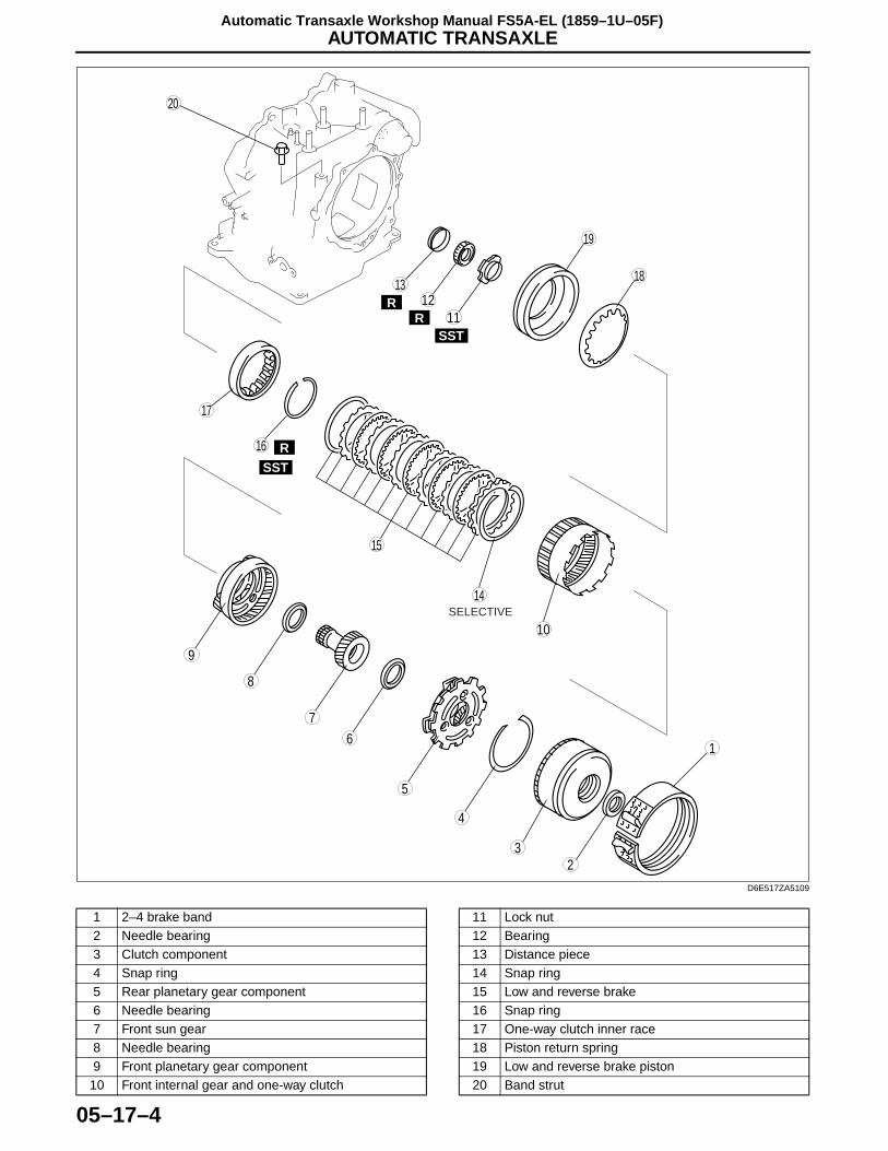
AUTOMATIC TRANSAXLE
05–17–4
Automatic Transaxle Workshop Manual FS5A-EL (1859–1U–05F)
.
19
18
17
15
14
10
1
2
4
5
7
9
16 R
13R 12
R 11RSST
SST
3
6
8
20
SELECTIVE
D6E517ZA5109
1 2–4 brake band2 Needle bearing3 Clutch component4 Snap ring5 Rear planetary gear component6 Needle bearing7 Front sun gear8 Needle bearing9 Front planetary gear component
10 Front internal gear and one-way clutch
11 Lock nut12 Bearing13 Distance piece14 Snap ring15 Low and reverse brake16 Snap ring17 One-way clutch inner race18 Piston return spring19 Low and reverse brake piston20 Band strut
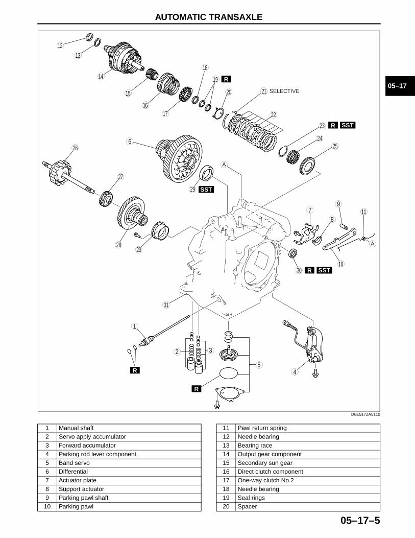
AUTOMATIC TRANSAXLE
05–17–5
05–17
.
6
SST
SST
R
R
R
A
A
8
9
10
11
45
32
1
17
7
18
SSTR
12
13
14
15
16
2120
19
28
27
252624
23
22
29
30
R
31
29
SELECTIVE
D6E517ZA5110
1 Manual shaft2 Servo apply accumulator3 Forward accumulator4 Parking rod lever component5 Band servo6 Differential7 Actuator plate8 Support actuator9 Parking pawl shaft10 Parking pawl
11 Pawl return spring12 Needle bearing13 Bearing race14 Output gear component15 Secondary sun gear16 Direct clutch component17 One-way clutch No.218 Needle bearing19 Seal rings20 Spacer
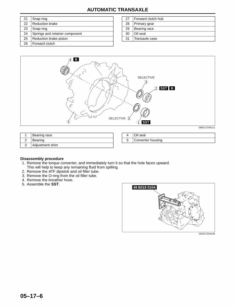
AUTOMATIC TRANSAXLE
05–17–6
.
Disassembly procedure1. Remove the torque converter, and immediately turn it so that the hole faces upward.
This will help to keep any remaining fluid from spilling. 2. Remove the ATF dipstick and oil filler tube.3. Remove the O-ring from the oil filler tube.4. Remove the breather hose.5. Assemble the SST.
21 Snap ring22 Reduction brake23 Snap ring24 Springs and retainer component25 Reduction brake piston26 Forward clutch
27 Forward clutch hub28 Primary gear29 Bearing race30 Oil seal31 Transaxle case
SST
SST
R
3
1
4
53
2 R
SELECTIVE
SELECTIVE
D6E517ZA5111
1 Bearing race2 Bearing3 Adjustment shim
4 Oil seal5 Converter housing
49 B019 010A
D6J517ZA4130
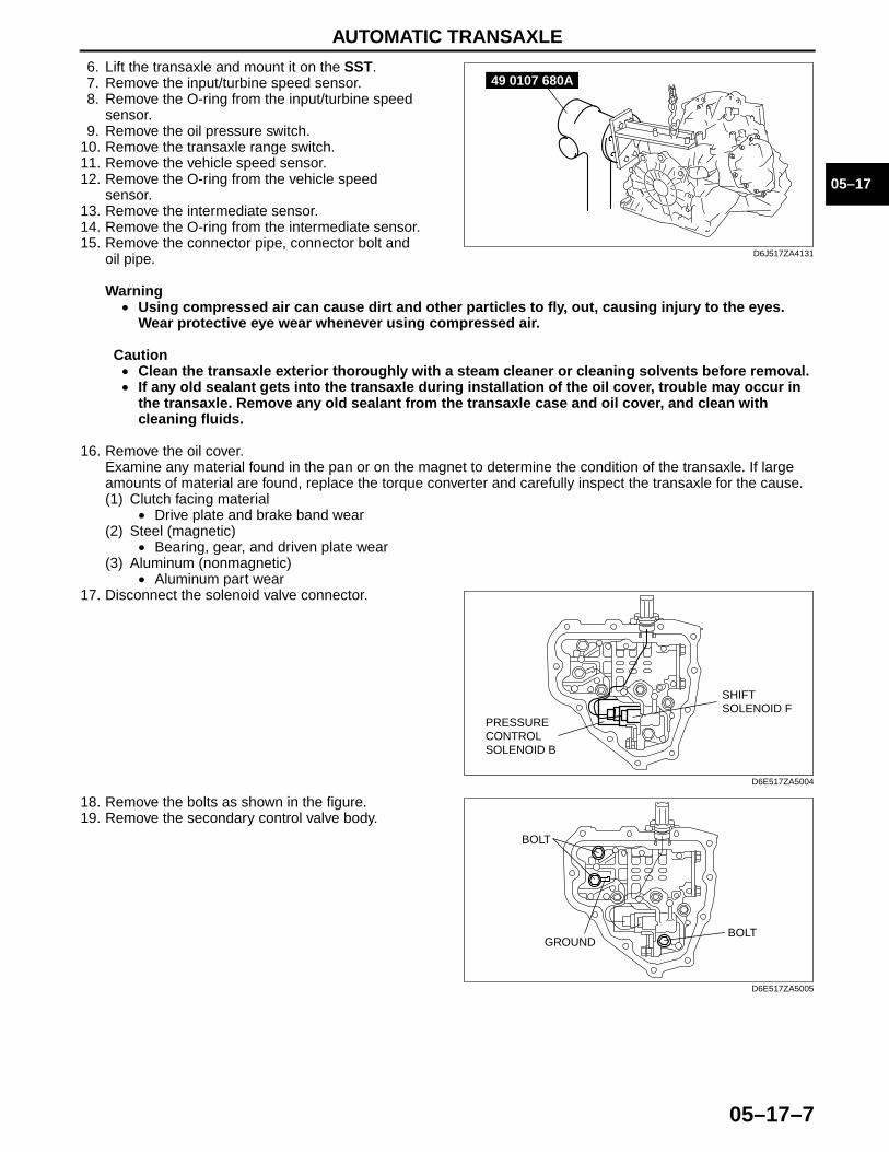
AUTOMATIC TRANSAXLE
05–17–7
05–17
6. Lift the transaxle and mount it on the SST.7. Remove the input/turbine speed sensor.8. Remove the O-ring from the input/turbine speed
sensor.9. Remove the oil pressure switch.
10. Remove the transaxle range switch.11. Remove the vehicle speed sensor.12. Remove the O-ring from the vehicle speed
sensor.13. Remove the intermediate sensor.14. Remove the O-ring from the intermediate sensor.15. Remove the connector pipe, connector bolt and
oil pipe.
Warning• Using compressed air can cause dirt and other particles to fly, out, causing injury to the eyes.
Wear protective eye wear whenever using compressed air.
Caution• Clean the transaxle exterior thoroughly with a steam cleaner or cleaning solvents before removal.• If any old sealant gets into the transaxle during installation of the oil cover, trouble may occur in
the transaxle. Remove any old sealant from the transaxle case and oil cover, and clean with cleaning fluids.
16. Remove the oil cover.Examine any material found in the pan or on the magnet to determine the condition of the transaxle. If large amounts of material are found, replace the torque converter and carefully inspect the transaxle for the cause.(1) Clutch facing material
• Drive plate and brake band wear(2) Steel (magnetic)
• Bearing, gear, and driven plate wear(3) Aluminum (nonmagnetic)
• Aluminum part wear17. Disconnect the solenoid valve connector.
18. Remove the bolts as shown in the figure.19. Remove the secondary control valve body.
49 0107 680A
D6J517ZA4131
SHIFTSOLENOID F
PRESSURECONTROLSOLENOID B
D6E517ZA5004
BOLT
BOLTGROUND
D6E517ZA5005
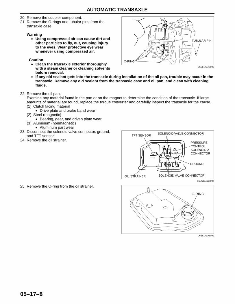
AUTOMATIC TRANSAXLE
05–17–8
20. Remove the coupler component.21. Remove the O-rings and tubular pins from the
transaxle case.
Warning• Using compressed air can cause dirt and
other particles to fly, out, causing injury to the eyes. Wear protective eye wear whenever using compressed air.
Caution• Clean the transaxle exterior thoroughly
with a steam cleaner or cleaning solvents before removal.
• If any old sealant gets into the transaxle during installation of the oil pan, trouble may occur in the transaxle. Remove any old sealant from the transaxle case and oil pan, and clean with cleaning fluids.
22. Remove the oil pan.Examine any material found in the pan or on the magnet to determine the condition of the transaxle. If large amounts of material are found, replace the torque converter and carefully inspect the transaxle for the cause.(1) Clutch facing material
• Drive plate and brake band wear(2) Steel (magnetic)
• Bearing, gear, and driven plate wear(3) Aluminum (nonmagnetic)
• Aluminum part wear23. Disconnect the solenoid valve connector, ground,
and TFT sensor.24. Remove the oil strainer.
25. Remove the O-ring from the oil strainer.
TUBULAR PIN
O-RING
D6E517ZA5009
TFT SENSORSOLENOID VALVE CONNECTOR
PRESSURE CONTROL SOLENOID A CONNECTOR
GROUND
SOLENOID VALVE CONNECTOROIL STRAINERE6U517AW5007
O-RING
D6E517ZA5099
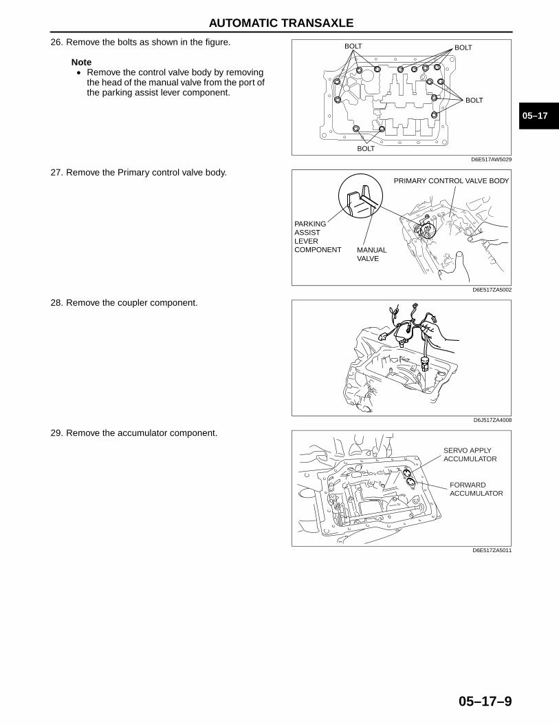
AUTOMATIC TRANSAXLE
05–17–9
05–17
26. Remove the bolts as shown in the figure.
Note• Remove the control valve body by removing
the head of the manual valve from the port of the parking assist lever component.
27. Remove the Primary control valve body.
28. Remove the coupler component.
29. Remove the accumulator component.
BOLT
BOLT
BOLT
BOLT
D6E517AW5029
PARKINGASSISTLEVERCOMPONENT MANUAL
VALVE
PRIMARY CONTROL VALVE BODY
D6E517ZA5002
D6J517ZA4008
FORWARDACCUMULATOR
SERVO APPLYACCUMULATOR
D6E517ZA5011
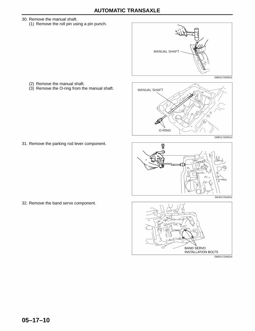
AUTOMATIC TRANSAXLE
05–17–10
30. Remove the manual shaft.(1) Remove the roll pin using a pin punch.
(2) Remove the manual shaft.(3) Remove the O-ring from the manual shaft.
31. Remove the parking rod lever component.
32. Remove the band servo component.
MANUAL SHAFT
D6E517ZA5012
MANUAL SHAFT
O-RING
D6E517ZA5013
D6J517ZA4012
BAND SERVO INSTALLATION BOLTS
D6E517ZA5014

AUTOMATIC TRANSAXLE
05–17–11
05–17
33. Remove the oil pump.
34. Remove the converter housing by tapping lightly with a plastic hammer.
35. Remove the forward clutch component.
36. Remove the differential.
37. Remove the actuator plate.
D6J517ZA4014
D6J517ZA4015
D6J517ZA4016
D6J517ZA4017
ACTUATOR PLATEINSTALLATION BOLTS
D6E517ZA5015
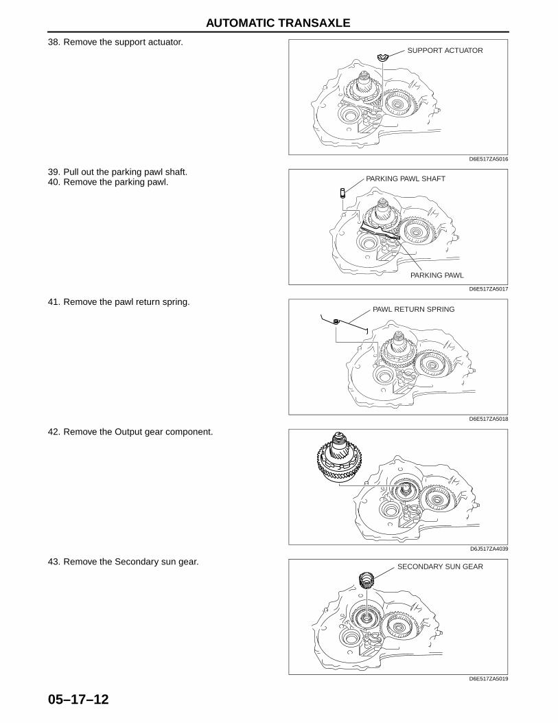
AUTOMATIC TRANSAXLE
05–17–12
38. Remove the support actuator.
39. Pull out the parking pawl shaft.40. Remove the parking pawl.
41. Remove the pawl return spring.
42. Remove the Output gear component.
43. Remove the Secondary sun gear.
SUPPORT ACTUATOR
D6E517ZA5016
PARKING PAWL
PARKING PAWL SHAFT
D6E517ZA5017
PAWL RETURN SPRING
D6E517ZA5018
D6J517ZA4039
SECONDARY SUN GEAR
D6E517ZA5019
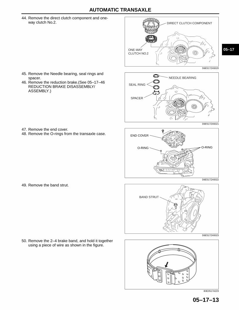
AUTOMATIC TRANSAXLE
05–17–13
05–17
44. Remove the direct clutch component and one-way clutch No.2.
45. Remove the Needle bearing, seal rings and spacer.
46. Remove the reduction brake.(See 05–17–46 REDUCTION BRAKE DISASSEMBLY/ASSEMBLY.)
47. Remove the end cover.48. Remove the O-rings from the transaxle case.
49. Remove the band strut.
50. Remove the 2–4 brake band, and hold it together using a piece of wire as shown in the figure.
ONE-WAY CLUTCH NO.2
DIRECT CLUTCH COMPONENT
D6E517ZA5020
SEAL RING
NEEDLE BEARING
SPACER
D6E517ZA5021
O-RINGO-RING
END COVER
D6E517ZA5022
BAND STRUT
D6E517ZA5023
B3E0517A223
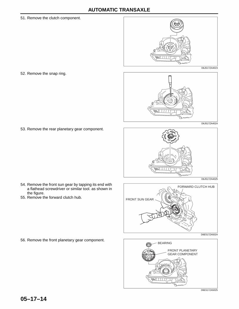
AUTOMATIC TRANSAXLE
05–17–14
51. Remove the clutch component.
52. Remove the snap ring.
53. Remove the rear planetary gear component.
54. Remove the front sun gear by tapping its end with a flathead screwdriver or similar tool. as shown in the figure.
55. Remove the forward clutch hub.
56. Remove the front planetary gear component.
D6J517ZA4023
D6J517ZA4024
D6J517ZA4025
FRONT SUN GEAR
FORWARD CLUTCH HUB
D6E517ZA5024
FRONT PLANETARYGEAR COMPONENT
BEARING
D6E517ZA5025
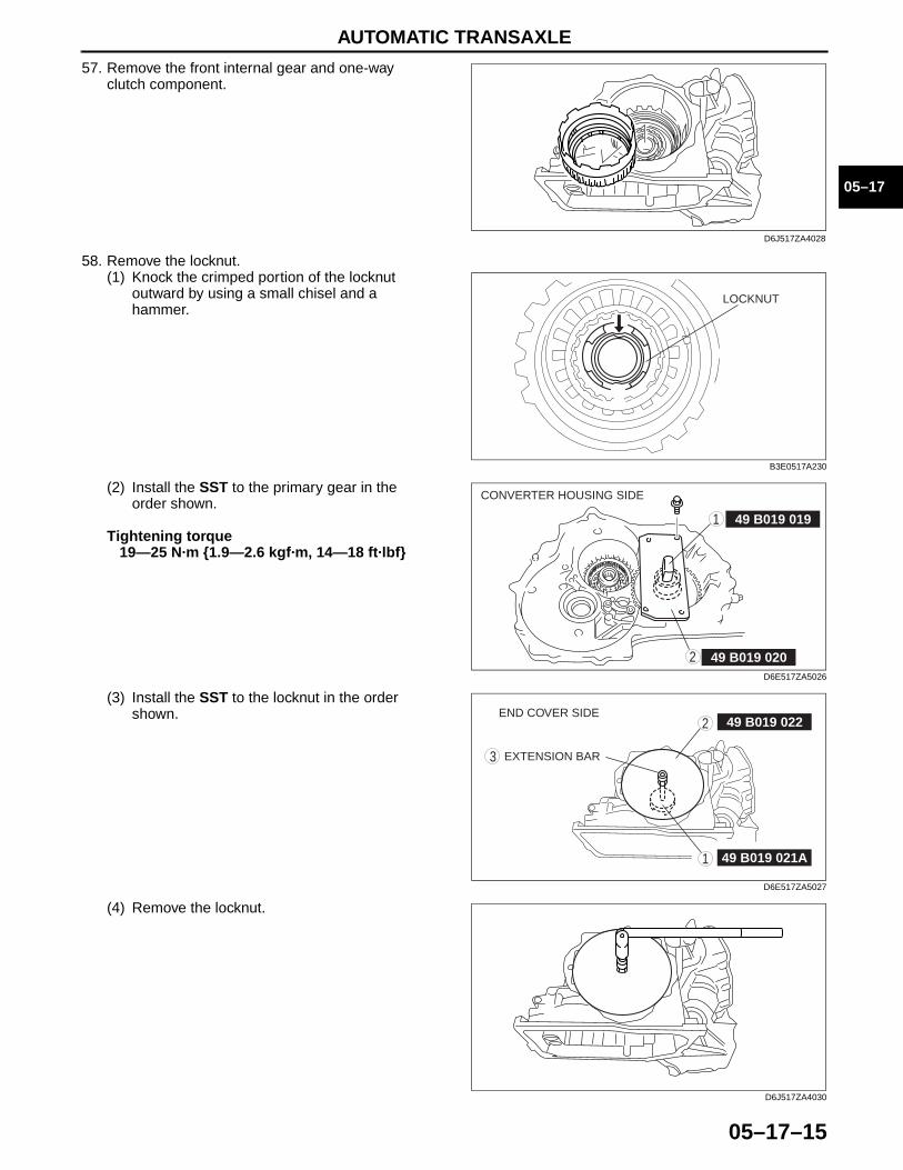
AUTOMATIC TRANSAXLE
05–17–15
05–17
57. Remove the front internal gear and one-way clutch component.
58. Remove the locknut.(1) Knock the crimped portion of the locknut
outward by using a small chisel and a hammer.
(2) Install the SST to the primary gear in the order shown.
Tightening torque19—25 N·m {1.9—2.6 kgf·m, 14—18 ft·lbf}
(3) Install the SST to the locknut in the order shown.
(4) Remove the locknut.
D6J517ZA4028
LOCKNUT
B3E0517A230
49 B019 019
49 B019 020
1
2
CONVERTER HOUSING SIDE
D6E517ZA5026
49 B019 0222
3
1 49 B019 021A
EXTENSION BAR
END COVER SIDE
D6E517ZA5027
D6J517ZA4030
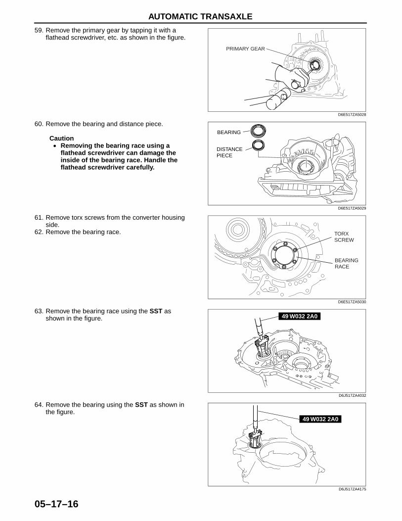
AUTOMATIC TRANSAXLE
05–17–16
59. Remove the primary gear by tapping it with a flathead screwdriver, etc. as shown in the figure.
60. Remove the bearing and distance piece.
Caution• Removing the bearing race using a
flathead screwdriver can damage the inside of the bearing race. Handle the flathead screwdriver carefully.
61. Remove torx screws from the converter housing side.
62. Remove the bearing race.
63. Remove the bearing race using the SST as shown in the figure.
64. Remove the bearing using the SST as shown in the figure.
End Of Sie
PRIMARY GEAR
D6E517ZA5028
BEARING
DISTANCEPIECE
D6E517ZA5029
TORX SCREW
BEARING RACE
D6E517ZA5030
49 W032 2A0
D6J517ZA4032
49 W032 2A0
D6J517ZA4175
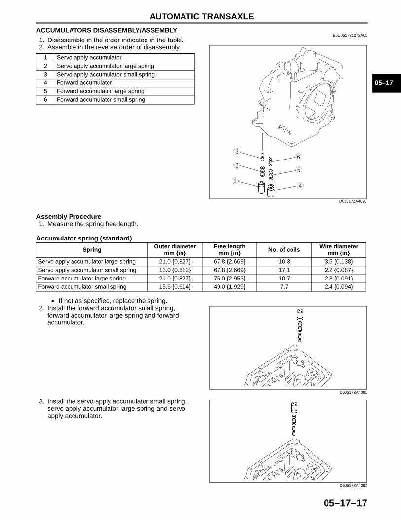
AUTOMATIC TRANSAXLE
05–17–17
05–17
ACCUMULATORS DISASSEMBLY/ASSEMBLYE6U051721272A01
1. Disassemble in the order indicated in the table.2. Assemble in the reverse order of disassembly.
Assembly Procedure1. Measure the spring free length.
Accumulator spring (standard)
• If not as specified, replace the spring.2. Install the forward accumulator small spring,
forward accumulator large spring and forward accumulator.
3. Install the servo apply accumulator small spring, servo apply accumulator large spring and servo apply accumulator.
End Of Sie
1 Servo apply accumulator2 Servo apply accumulator large spring3 Servo apply accumulator small spring4 Forward accumulator5 Forward accumulator large spring6 Forward accumulator small spring
1
36
5
4
2
D6J517ZA4090
Spring Outer diameter mm {in}
Free length mm {in} No. of coils Wire diameter
mm {in}Servo apply accumulator large spring 21.0 {0.827} 67.8 {2.669} 10.3 3.5 {0.138}Servo apply accumulator small spring 13.0 {0.512} 67.8 {2.669} 17.1 2.2 {0.087}Forward accumulator large spring 21.0 {0.827} 75.0 {2.953} 10.7 2.3 {0.091}Forward accumulator small spring 15.6 {0.614} 49.0 {1.929} 7.7 2.4 {0.094}
D6J517ZA4091
D6J517ZA4092

AUTOMATIC TRANSAXLE
05–17–18
OIL PUMP DISASSEMBLY/ASSEMBLYE6U051719220A04
1. Perform the preinspection before disassembly.(See 05–17–106 Oil Pump Preinspection.)
2. Disassemble in the order indicated in the table.3. Assemble in the reverse order of disassembly.
Oil Pump Cover Disassembly Note• Loosen the mounting bolts evenly in the pattern
shown and remove the oil pump cover from the oil pump housing.
ATF
ATF
ATF
ATF
ATF
R
RR
8
7
54
3
1
2
6
P
8.1—10.9 N·m {83—111 kgf·cm, 72—96 in·lbf}
D6E517ZA5031
1 Thrust washer2 Seal rings3 O-ring4 Oil pump cover
(See 05–17–18 Oil Pump Cover Disassembly Note.)5 Inner rotor
(See 05–17–19 Inner Rotor, Outer Rotor Disassembly Note.)
6 Outer rotor(See 05–17–19 Inner Rotor, Outer Rotor Disassembly Note.)
7 Oil seal8 Oil pump housing
54
31
2
6
D6J517ZA4129
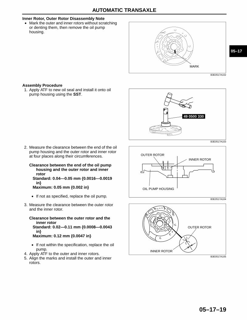
AUTOMATIC TRANSAXLE
05–17–19
05–17
Inner Rotor, Outer Rotor Disassembly Note• Mark the outer and inner rotors without scratching
or denting them, then remove the oil pump housing.
Assembly Procedure1. Apply ATF to new oil seal and install it onto oil
pump housing using the SST.
2. Measure the clearance between the end of the oil pump housing and the outer rotor and inner rotor at four places along their circumferences.
Clearance between the end of the oil pump housing and the outer rotor and inner rotor
Standard: 0.04—0.05 mm {0.0016—0.0019 in}
Maximum: 0.05 mm {0.002 in}
• If not as specified, replace the oil pump.
3. Measure the clearance between the outer rotor and the inner rotor.
Clearance between the outer rotor and the inner rotor
Standard: 0.02—0.11 mm {0.0008—0.0043 in}
Maximum: 0.12 mm {0.0047 in}
• If not within the specification, replace the oil pump.
4. Apply ATF to the outer and inner rotors.5. Align the marks and install the outer and inner
rotors.
MARK
B3E0517A102
49 0500 330
B3E0517A103
OUTER ROTORINNER ROTOR
OIL PUMP HOUSING
B3E0517A104
OUTER ROTOR
INNER ROTOR
B3E0517A105
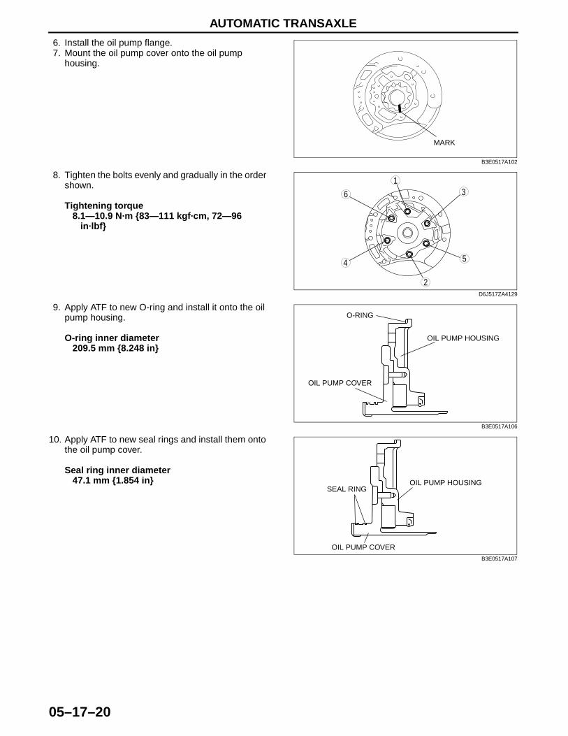
AUTOMATIC TRANSAXLE
05–17–20
6. Install the oil pump flange.7. Mount the oil pump cover onto the oil pump
housing.
8. Tighten the bolts evenly and gradually in the order shown.
Tightening torque8.1—10.9 N·m {83—111 kgf·cm, 72—96
in·lbf}
9. Apply ATF to new O-ring and install it onto the oil pump housing.
O-ring inner diameter209.5 mm {8.248 in}
10. Apply ATF to new seal rings and install them onto the oil pump cover.
Seal ring inner diameter47.1 mm {1.854 in}
End Of Sie
MARK
B3E0517A102
54
31
2
6
D6J517ZA4129
OIL PUMP HOUSING
OIL PUMP COVER
O-RING
B3E0517A106
OIL PUMP HOUSINGSEAL RING
OIL PUMP COVER
B3E0517A107
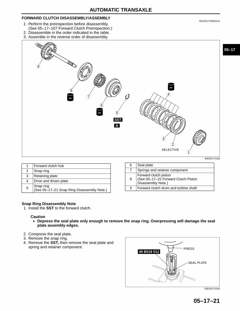
AUTOMATIC TRANSAXLE
05–17–21
05–17
FORWARD CLUTCH DISASSEMBLY/ASSEMBLYE6U051719500A13
1. Perform the preinspection before disassembly.(See 05–17–107 Forward Clutch Preinspection.)
2. Disassemble in the order indicated in the table.3. Assemble in the reverse order of disassembly.
Snap Ring Disassembly Note1. Install the SST to the forward clutch.
Caution• Depress the seal plate only enough to remove the snap ring. Overpressing will damage the seal
plate assembly edges.
2. Compress the seal plate.3. Remove the snap ring.4. Remove the SST, then remove the seal plate and
spring and retainer component.
ATF
ATF
ATF
SELECTIVE
SST
R
9
8
7
5
4
3
1
2
6
B3E0517A108
1 Forward clutch hub2 Snap ring3 Retaining plate4 Drive and driven plate
5 Snap ring(See 05–17–21 Snap Ring Disassembly Note.)
6 Seal plate7 Springs and retainer component
8Forward clutch piston(See 05–17–22 Forward Clutch Piston Disassembly Note.)
9 Forward clutch drum and turbine shaft
49 B019 012
SEAL PLATE
PRESS
B3E0517A109
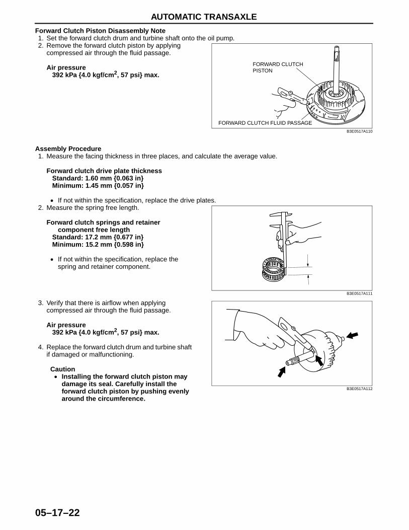
AUTOMATIC TRANSAXLE
05–17–22
Forward Clutch Piston Disassembly Note1. Set the forward clutch drum and turbine shaft onto the oil pump.2. Remove the forward clutch piston by applying
compressed air through the fluid passage.
Air pressure392 kPa {4.0 kgf/cm2, 57 psi} max.
Assembly Procedure1. Measure the facing thickness in three places, and calculate the average value.
Forward clutch drive plate thicknessStandard: 1.60 mm {0.063 in}Minimum: 1.45 mm {0.057 in}
• If not within the specification, replace the drive plates.2. Measure the spring free length.
Forward clutch springs and retainer component free length
Standard: 17.2 mm {0.677 in}Minimum: 15.2 mm {0.598 in}
• If not within the specification, replace the spring and retainer component.
3. Verify that there is airflow when applying compressed air through the fluid passage.
Air pressure392 kPa {4.0 kgf/cm2, 57 psi} max.
4. Replace the forward clutch drum and turbine shaft if damaged or malfunctioning.
Caution• Installing the forward clutch piston may
damage its seal. Carefully install the forward clutch piston by pushing evenly around the circumference.
FORWARD CLUTCH PISTON
FORWARD CLUTCH FLUID PASSAGE
B3E0517A110
B3E0517A111
B3E0517A112

AUTOMATIC TRANSAXLE
05–17–23
05–17
5. Apply ATF to the circumference of the forward clutch piston seal, and install the piston into the forward clutch drum and turbine shaft.
6. Install the spring and retainer component.
7. Apply ATF to the seal plate, and install it onto the forward clutch drum.
8. Install the SST to the forward clutch drum and turbine shaft as shown.
Caution• Depress the seal plate only enough to
remove the snap ring. Overpressing will damage the seal plate assembly edges.
9. Compress the seal plate.10. Install the snap ring.11. Remove the SST.
12. Install the drive and driven plates in the following order.Driven—Drive—Driven—Drive—Driven—Drive—Driven—Drive
13. Install the retaining plate.14. Install the snap ring.
FORWARD CLUTCH PISTON
FORWARD CLUTCH DRUM AND TURBINE SHAFT
B3E0517A113
SEAL PLATESPRING AND RETAINER COMPONENT
B3E0517A114
49 B019 012
SEAL PLATE
PRESS
B3E0517A109
SNAP RING
RETAINING PLATE
DRIVE AND DRIVEN PLATE
B3E0517A115
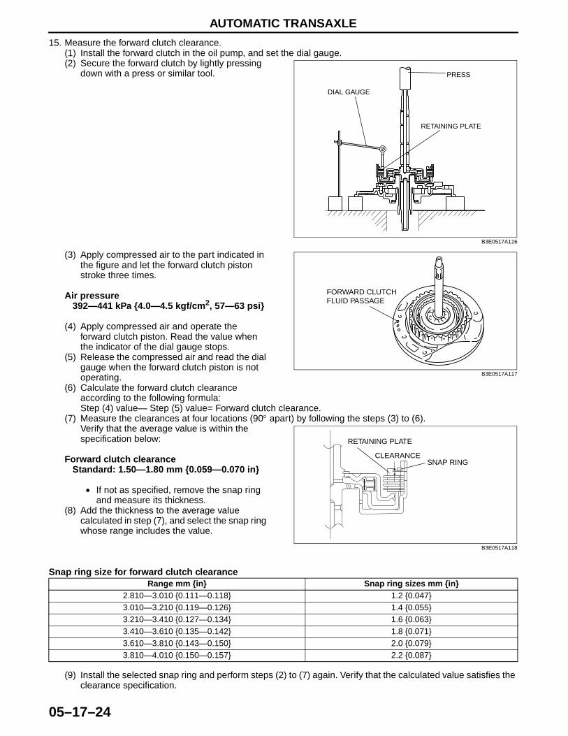
AUTOMATIC TRANSAXLE
05–17–24
15. Measure the forward clutch clearance.(1) Install the forward clutch in the oil pump, and set the dial gauge.(2) Secure the forward clutch by lightly pressing
down with a press or similar tool.
(3) Apply compressed air to the part indicated in the figure and let the forward clutch piston stroke three times.
Air pressure392—441 kPa {4.0—4.5 kgf/cm2, 57—63 psi}
(4) Apply compressed air and operate the forward clutch piston. Read the value when the indicator of the dial gauge stops.
(5) Release the compressed air and read the dial gauge when the forward clutch piston is not operating.
(6) Calculate the forward clutch clearance according to the following formula:Step (4) value— Step (5) value= Forward clutch clearance.
(7) Measure the clearances at four locations (90° apart) by following the steps (3) to (6).Verify that the average value is within the specification below:
Forward clutch clearanceStandard: 1.50—1.80 mm {0.059—0.070 in}
• If not as specified, remove the snap ring and measure its thickness.
(8) Add the thickness to the average value calculated in step (7), and select the snap ring whose range includes the value.
Snap ring size for forward clutch clearance
(9) Install the selected snap ring and perform steps (2) to (7) again. Verify that the calculated value satisfies the clearance specification.
PRESS
DIAL GAUGE
RETAINING PLATE
B3E0517A116
FORWARD CLUTCH FLUID PASSAGE
B3E0517A117
SNAP RING
RETAINING PLATE
CLEARANCE
B3E0517A118
Range mm {in} Snap ring sizes mm {in}2.810—3.010 {0.111—0.118} 1.2 {0.047}3.010—3.210 {0.119—0.126} 1.4 {0.055}3.210—3.410 {0.127—0.134} 1.6 {0.063}3.410—3.610 {0.135—0.142} 1.8 {0.071}3.610—3.810 {0.143—0.150} 2.0 {0.079}3.810—4.010 {0.150—0.157} 2.2 {0.087}
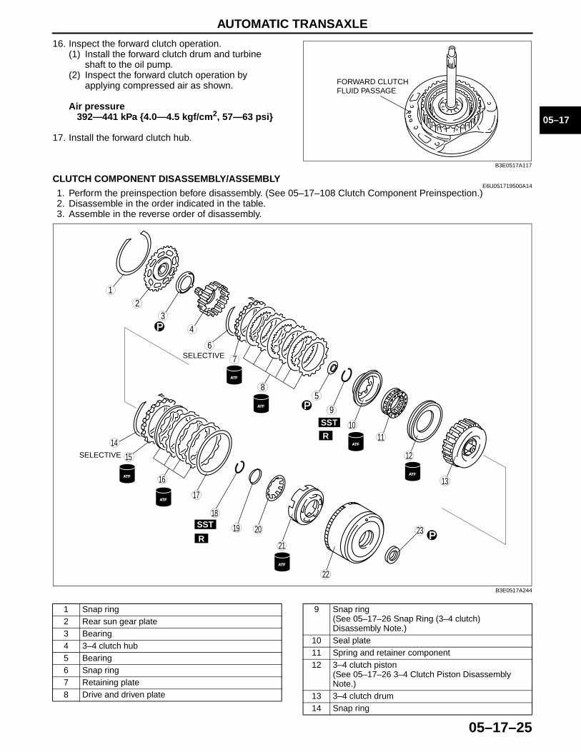
AUTOMATIC TRANSAXLE
05–17–25
05–17
16. Inspect the forward clutch operation.(1) Install the forward clutch drum and turbine
shaft to the oil pump.(2) Inspect the forward clutch operation by
applying compressed air as shown.
Air pressure392—441 kPa {4.0—4.5 kgf/cm2, 57—63 psi}
17. Install the forward clutch hub.End Of Sie
CLUTCH COMPONENT DISASSEMBLY/ASSEMBLYE6U051719500A14
1. Perform the preinspection before disassembly. (See 05–17–108 Clutch Component Preinspection.)2. Disassemble in the order indicated in the table. 3. Assemble in the reverse order of disassembly.
.
FORWARD CLUTCH FLUID PASSAGE
B3E0517A117
ATF
ATF
ATF
ATF
ATF
ATF ATF
P
P
P
12
34
6
85
9
10
14
15
17
18
19 20
21
22
16
11
12
13
7
23
SST
SST
R
R
SELECTIVE
SELECTIVE
B3E0517A244
1 Snap ring2 Rear sun gear plate3 Bearing4 3–4 clutch hub5 Bearing6 Snap ring7 Retaining plate8 Drive and driven plate
9 Snap ring(See 05–17–26 Snap Ring (3–4 clutch) Disassembly Note.)
10 Seal plate11 Spring and retainer component12 3–4 clutch piston
(See 05–17–26 3–4 Clutch Piston Disassembly Note.)
13 3–4 clutch drum14 Snap ring
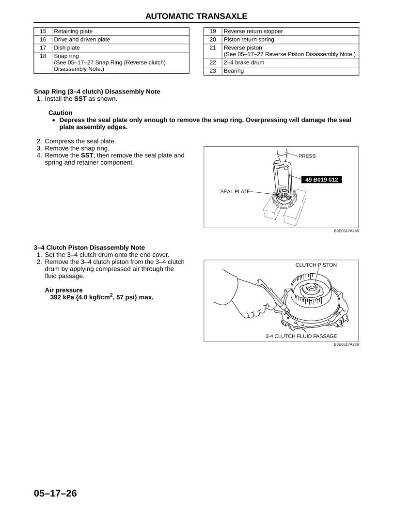
AUTOMATIC TRANSAXLE
05–17–26
Snap Ring (3–4 clutch) Disassembly Note1. Install the SST as shown.
Caution• Depress the seal plate only enough to remove the snap ring. Overpressing will damage the seal
plate assembly edges.
2. Compress the seal plate.3. Remove the snap ring.4. Remove the SST, then remove the seal plate and
spring and retainer component.
3–4 Clutch Piston Disassembly Note1. Set the 3–4 clutch drum onto the end cover.2. Remove the 3–4 clutch piston from the 3–4 clutch
drum by applying compressed air through the fluid passage.
Air pressure392 kPa {4.0 kgf/cm2, 57 psi} max.
15 Retaining plate16 Drive and driven plate17 Dish plate18 Snap ring
(See 05–17–27 Snap Ring (Reverse clutch) Disassembly Note.)
19 Reverse return stopper20 Piston return spring21 Reverse piston
(See 05–17–27 Reverse Piston Disassembly Note.)22 2–4 brake drum23 Bearing
49 B019 012
SEAL PLATE
PRESS
B3E0517A245
CLUTCH PISTON
3-4 CLUTCH FLUID PASSAGE
B3E0517A246
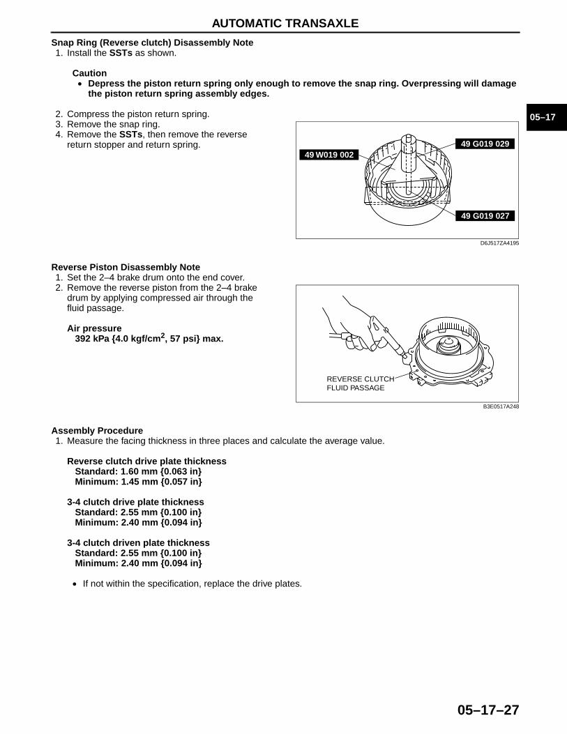
AUTOMATIC TRANSAXLE
05–17–27
05–17
Snap Ring (Reverse clutch) Disassembly Note1. Install the SSTs as shown.
Caution• Depress the piston return spring only enough to remove the snap ring. Overpressing will damage
the piston return spring assembly edges.
2. Compress the piston return spring.3. Remove the snap ring.4. Remove the SSTs, then remove the reverse
return stopper and return spring.
Reverse Piston Disassembly Note1. Set the 2–4 brake drum onto the end cover.2. Remove the reverse piston from the 2–4 brake
drum by applying compressed air through the fluid passage.
Air pressure392 kPa {4.0 kgf/cm2, 57 psi} max.
Assembly Procedure1. Measure the facing thickness in three places and calculate the average value.
Reverse clutch drive plate thicknessStandard: 1.60 mm {0.063 in}Minimum: 1.45 mm {0.057 in}
3-4 clutch drive plate thicknessStandard: 2.55 mm {0.100 in}Minimum: 2.40 mm {0.094 in}
3-4 clutch driven plate thicknessStandard: 2.55 mm {0.100 in}Minimum: 2.40 mm {0.094 in}
• If not within the specification, replace the drive plates.
49 G019 02949 W019 002
49 G019 027
D6J517ZA4195
REVERSE CLUTCHFLUID PASSAGE
B3E0517A248
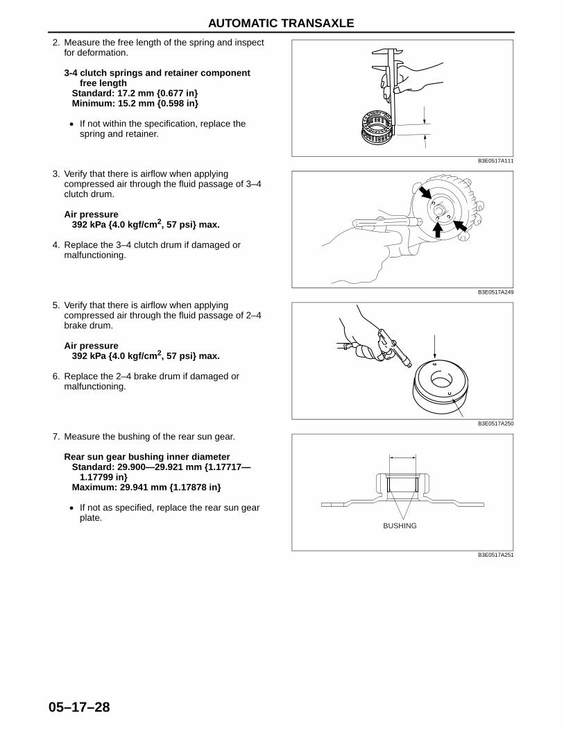
AUTOMATIC TRANSAXLE
05–17–28
2. Measure the free length of the spring and inspect for deformation.
3-4 clutch springs and retainer component free length
Standard: 17.2 mm {0.677 in}Minimum: 15.2 mm {0.598 in}
• If not within the specification, replace the spring and retainer.
3. Verify that there is airflow when applying compressed air through the fluid passage of 3–4 clutch drum.
Air pressure392 kPa {4.0 kgf/cm2, 57 psi} max.
4. Replace the 3–4 clutch drum if damaged or malfunctioning.
5. Verify that there is airflow when applying compressed air through the fluid passage of 2–4 brake drum.
Air pressure392 kPa {4.0 kgf/cm2, 57 psi} max.
6. Replace the 2–4 brake drum if damaged or malfunctioning.
7. Measure the bushing of the rear sun gear.
Rear sun gear bushing inner diameterStandard: 29.900—29.921 mm {1.17717—
1.17799 in}Maximum: 29.941 mm {1.17878 in}
• If not as specified, replace the rear sun gear plate.
B3E0517A111
B3E0517A249
B3E0517A250
BUSHING
B3E0517A251
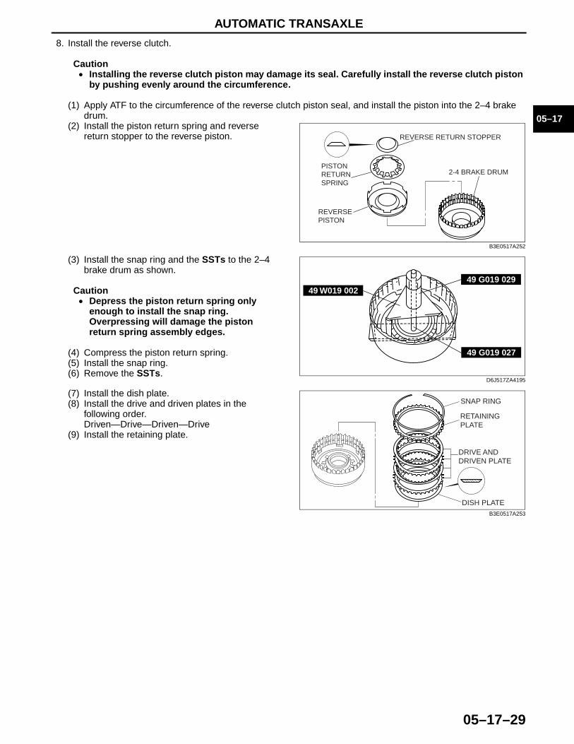
AUTOMATIC TRANSAXLE
05–17–29
05–17
8. Install the reverse clutch.
Caution• Installing the reverse clutch piston may damage its seal. Carefully install the reverse clutch piston
by pushing evenly around the circumference.
(1) Apply ATF to the circumference of the reverse clutch piston seal, and install the piston into the 2–4 brake drum.
(2) Install the piston return spring and reverse return stopper to the reverse piston.
(3) Install the snap ring and the SSTs to the 2–4 brake drum as shown.
Caution• Depress the piston return spring only
enough to install the snap ring. Overpressing will damage the piston return spring assembly edges.
(4) Compress the piston return spring.(5) Install the snap ring.(6) Remove the SSTs.
(7) Install the dish plate.(8) Install the drive and driven plates in the
following order.Driven—Drive—Driven—Drive
(9) Install the retaining plate.
REVERSE RETURN STOPPER
2-4 BRAKE DRUMPISTONRETURNSPRING
REVERSEPISTON
B3E0517A252
49 G019 02949 W019 002
49 G019 027
D6J517ZA4195
SNAP RING
RETAININGPLATE
DRIVE ANDDRIVEN PLATE
DISH PLATEB3E0517A253
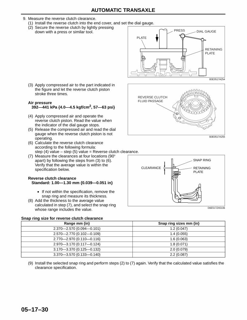
AUTOMATIC TRANSAXLE
05–17–30
9. Measure the reverse clutch clearance.(1) Install the reverse clutch into the end cover, and set the dial gauge.(2) Secure the reverse clutch by lightly pressing
down with a press or similar tool.
(3) Apply compressed air to the part indicated in the figure and let the reverse clutch piston stroke three times.
Air pressure392—441 kPa {4.0—4.5 kgf/cm2, 57—63 psi}
(4) Apply compressed air and operate the reverse clutch piston. Read the value when the indicator of the dial gauge stops.
(5) Release the compressed air and read the dial gauge when the reverse clutch piston is not operating.
(6) Calculate the reverse clutch clearance according to the following formula:step (4) value – step (5) value = Reverse clutch clearance.
(7) Measure the clearances at four locations (90° apart) by following the steps from (3) to (6). Verify that the average value is within the specification below.
Reverse clutch clearanceStandard: 1.00—1.30 mm {0.039—0.051 in}
• If not within the specification, remove the snap ring and measure its thickness.
(8) Add the thickness to the average value calculated in step (7), and select the snap ring whose range includes the value.
Snap ring size for reverse clutch clearance
(9) Install the selected snap ring and perform steps (2) to (7) again. Verify that the calculated value satisfies the clearance specification.
PLATE
PRESS
RETAINING PLATE
DIAL GAUGE
B3E0517A254
REVERSE CLUTCHFLUID PASSAGE
B3E0517A255
SNAP RING
CLEARANCE RETAINING PLATE
D6E517ZA5106
Range mm {in} Snap ring sizes mm {in}2.370—2.570 {0.094—0.101} 1.2 {0.047}2.570—2.770 {0.102—0.109} 1.4 {0.055}2.770—2.970 {0.110—0.116} 1.6 {0.063}2.970—3.170 {0.117—0.124} 1.8 {0.071}3.170—3.370 {0.125—0.132} 2.0 {0.079}3.370—3.570 {0.133—0.140} 2.2 {0.087}
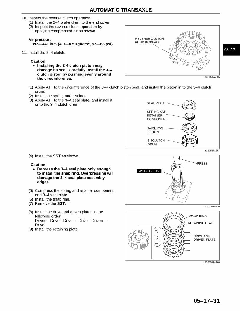
AUTOMATIC TRANSAXLE
05–17–31
05–17
10. Inspect the reverse clutch operation. (1) Install the 2–4 brake drum to the end cover.(2) Inspect the reverse clutch operation by
applying compressed air as shown.
Air pressure392—441 kPa {4.0—4.5 kgf/cm2, 57—63 psi}
11. Install the 3–4 clutch.
Caution• Installing the 3-4 clutch piston may
damage its seal. Carefully install the 3–4 clutch piston by pushing evenly around the circumference.
(1) Apply ATF to the circumference of the 3–4 clutch piston seal, and install the piston in to the 3–4 clutch drum.
(2) Install the spring and retainer.(3) Apply ATF to the 3–4 seal plate, and install it
onto the 3–4 clutch drum.
(4) Install the SST as shown.
Caution• Depress the 3–4 seal plate only enough
to install the snap ring. Overpressing will damage the 3–4 seal plate assembly edges.
(5) Compress the spring and retainer component and 3–4 seal plate.
(6) Install the snap ring.(7) Remove the SST.
(8) Install the drive and driven plates in the following order.Driven—Drive—Driven—Drive—Driven—Drive
(9) Install the retaining plate.
REVERSE CLUTCHFLUID PASSAGE
B3E0517A255
SEAL PLATE
SPRING ANDRETAINERCOMPONENT
3-4CLUTCHPISTON
3-4CLUTCHDRUM
B3E0517A257
49 B019 012
PRESS
B3E0517A258
SNAP RING
RETAINING PLATE
DRIVE AND DRIVEN PLATE
B3E0517A260
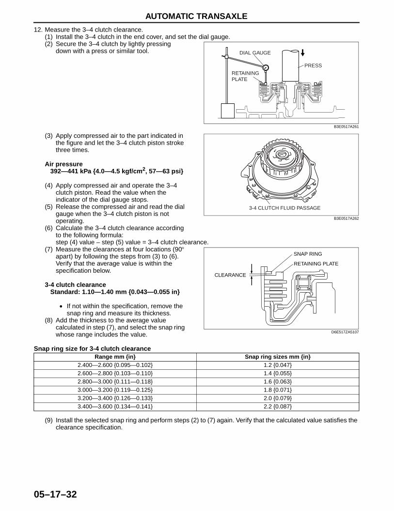
AUTOMATIC TRANSAXLE
05–17–32
12. Measure the 3–4 clutch clearance.(1) Install the 3–4 clutch in the end cover, and set the dial gauge.(2) Secure the 3–4 clutch by lightly pressing
down with a press or similar tool.
(3) Apply compressed air to the part indicated in the figure and let the 3–4 clutch piston stroke three times.
Air pressure392—441 kPa {4.0—4.5 kgf/cm2, 57—63 psi}
(4) Apply compressed air and operate the 3–4 clutch piston. Read the value when the indicator of the dial gauge stops.
(5) Release the compressed air and read the dial gauge when the 3–4 clutch piston is not operating.
(6) Calculate the 3–4 clutch clearance according to the following formula:step (4) value – step (5) value = 3–4 clutch clearance.
(7) Measure the clearances at four locations (90° apart) by following the steps from (3) to (6). Verify that the average value is within the specification below.
3-4 clutch clearanceStandard: 1.10—1.40 mm {0.043—0.055 in}
• If not within the specification, remove the snap ring and measure its thickness.
(8) Add the thickness to the average value calculated in step (7), and select the snap ring whose range includes the value.
Snap ring size for 3-4 clutch clearance
(9) Install the selected snap ring and perform steps (2) to (7) again. Verify that the calculated value satisfies the clearance specification.
DIAL GAUGE
RETAININGPLATE
PRESS
B3E0517A261
3-4 CLUTCH FLUID PASSAGE
B3E0517A262
SNAP RING
CLEARANCE
RETAINING PLATE
D6E517ZA5107
Range mm {in} Snap ring sizes mm {in}2.400—2.600 {0.095—0.102} 1.2 {0.047}2.600—2.800 {0.103—0.110} 1.4 {0.055}2.800—3.000 {0.111—0.118} 1.6 {0.063}3.000—3.200 {0.119—0.125} 1.8 {0.071}3.200—3.400 {0.126—0.133} 2.0 {0.079}3.400—3.600 {0.134—0.141} 2.2 {0.087}
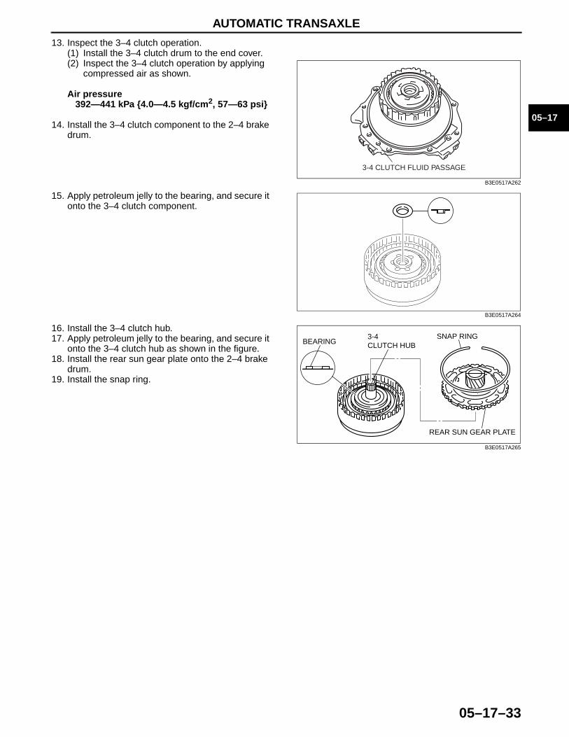
AUTOMATIC TRANSAXLE
05–17–33
05–17
13. Inspect the 3–4 clutch operation. (1) Install the 3–4 clutch drum to the end cover. (2) Inspect the 3–4 clutch operation by applying
compressed air as shown.
Air pressure392—441 kPa {4.0—4.5 kgf/cm2, 57—63 psi}
14. Install the 3–4 clutch component to the 2–4 brake drum.
15. Apply petroleum jelly to the bearing, and secure it onto the 3–4 clutch component.
16. Install the 3–4 clutch hub.17. Apply petroleum jelly to the bearing, and secure it
onto the 3–4 clutch hub as shown in the figure.18. Install the rear sun gear plate onto the 2–4 brake
drum.19. Install the snap ring.End Of Sie
3-4 CLUTCH FLUID PASSAGE
B3E0517A262
B3E0517A264
SNAP RING3-4CLUTCH HUBBEARING
REAR SUN GEAR PLATE
B3E0517A265
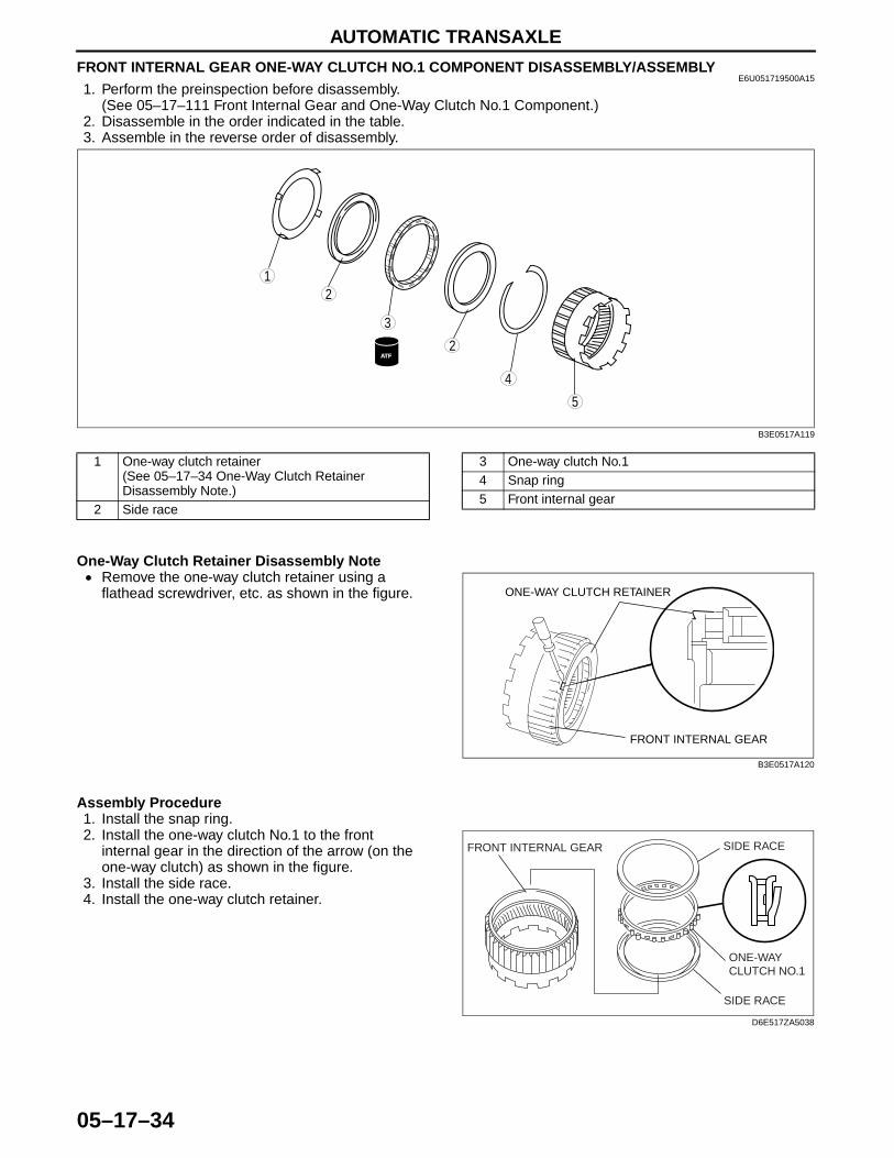
AUTOMATIC TRANSAXLE
05–17–34
FRONT INTERNAL GEAR ONE-WAY CLUTCH NO.1 COMPONENT DISASSEMBLY/ASSEMBLYE6U051719500A15
1. Perform the preinspection before disassembly.(See 05–17–111 Front Internal Gear and One-Way Clutch No.1 Component.)
2. Disassemble in the order indicated in the table.3. Assemble in the reverse order of disassembly..
One-Way Clutch Retainer Disassembly Note• Remove the one-way clutch retainer using a
flathead screwdriver, etc. as shown in the figure.
Assembly Procedure1. Install the snap ring.2. Install the one-way clutch No.1 to the front
internal gear in the direction of the arrow (on the one-way clutch) as shown in the figure.
3. Install the side race.4. Install the one-way clutch retainer.
End Of Sie
5
4
3
12
2ATF
B3E0517A119
1 One-way clutch retainer(See 05–17–34 One-Way Clutch Retainer Disassembly Note.)
2 Side race
3 One-way clutch No.14 Snap ring5 Front internal gear
FRONT INTERNAL GEAR
ONE-WAY CLUTCH RETAINER
B3E0517A120
FRONT INTERNAL GEAR SIDE RACE
SIDE RACE
ONE-WAY CLUTCH NO.1
D6E517ZA5038
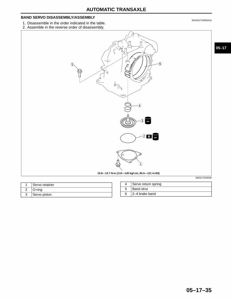
AUTOMATIC TRANSAXLE
05–17–35
05–17
BAND SERVO DISASSEMBLY/ASSEMBLYE6U051719500A16
1. Disassemble in the order indicated in the table.2. Assemble in the reverse order of disassembly.
5
4
3
1
2
6
R
ATF
ATF
10.8—13.7 N·m {110—140 kgf·cm, 95.5—121 in·lbf}
D6E517ZA5039
1 Servo retainer2 O-ring3 Servo piston
4 Servo return spring5 Band strut6 2–4 brake band

AUTOMATIC TRANSAXLE
05–17–36
Assembly Procedure1. Measure the spring free length.
Servo return spring (Standard)
• If not as specified, replace the spring.2. Install the servo return spring to the transaxle case.3. Install the servo piston to the transaxle case.
4. Apply ATF to new O-ring and install it to the transaxle case.
O-ring inner diameter70.2 mm {2.76 in}
5. Install the servo retainer by tightening the bolts evenly and gradually.
Tightening torque11—14 N·m
{113—142 kgf·cm, 97.4—123 in·lbf}
End Of Sie
Outer diameter mm {in} Free length mm {in} No. of coils Wire diametermm {in}
34.0 {1.340} 36.4 {1.430} 2.5 4.0 {0.160}
SERVO PISTON
SERVO RETURN SPRING
D6E517ZA5040
O-RING
D6E517ZA5041
BAND SERVO INSTALLATION BOLTS
D6E517ZA5014
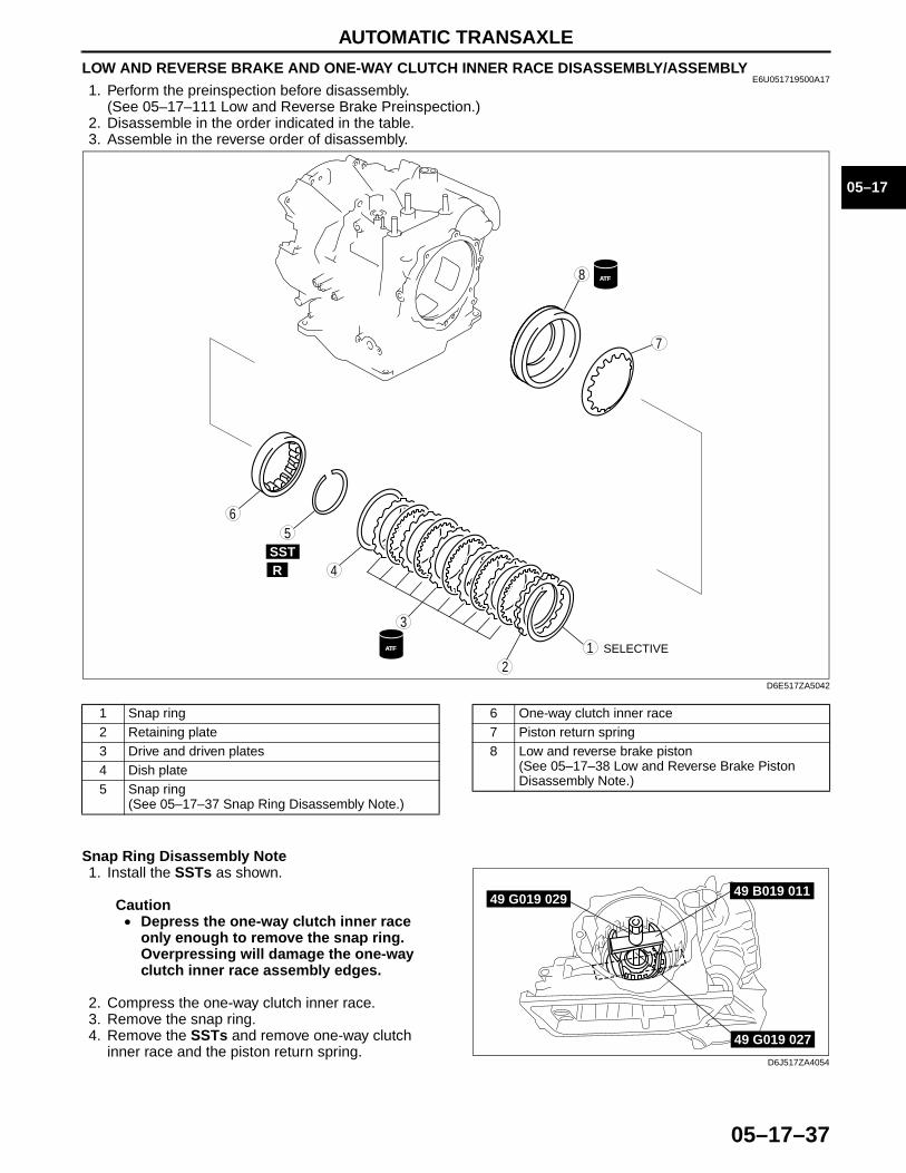
AUTOMATIC TRANSAXLE
05–17–37
05–17
LOW AND REVERSE BRAKE AND ONE-WAY CLUTCH INNER RACE DISASSEMBLY/ASSEMBLYE6U051719500A17
1. Perform the preinspection before disassembly.(See 05–17–111 Low and Reverse Brake Preinspection.)
2. Disassemble in the order indicated in the table.3. Assemble in the reverse order of disassembly..
Snap Ring Disassembly Note1. Install the SSTs as shown.
Caution• Depress the one-way clutch inner race
only enough to remove the snap ring.Overpressing will damage the one-way clutch inner race assembly edges.
2. Compress the one-way clutch inner race.3. Remove the snap ring.4. Remove the SSTs and remove one-way clutch
inner race and the piston return spring.
4
56
3
12
SSTR
7
8 ATFTF
ATFTF SELECTIVE
D6E517ZA5042
1 Snap ring2 Retaining plate3 Drive and driven plates4 Dish plate5 Snap ring
(See 05–17–37 Snap Ring Disassembly Note.)
6 One-way clutch inner race7 Piston return spring8 Low and reverse brake piston
(See 05–17–38 Low and Reverse Brake Piston Disassembly Note.)
49 B019 01149 G019 029
49 G019 027
D6J517ZA4054
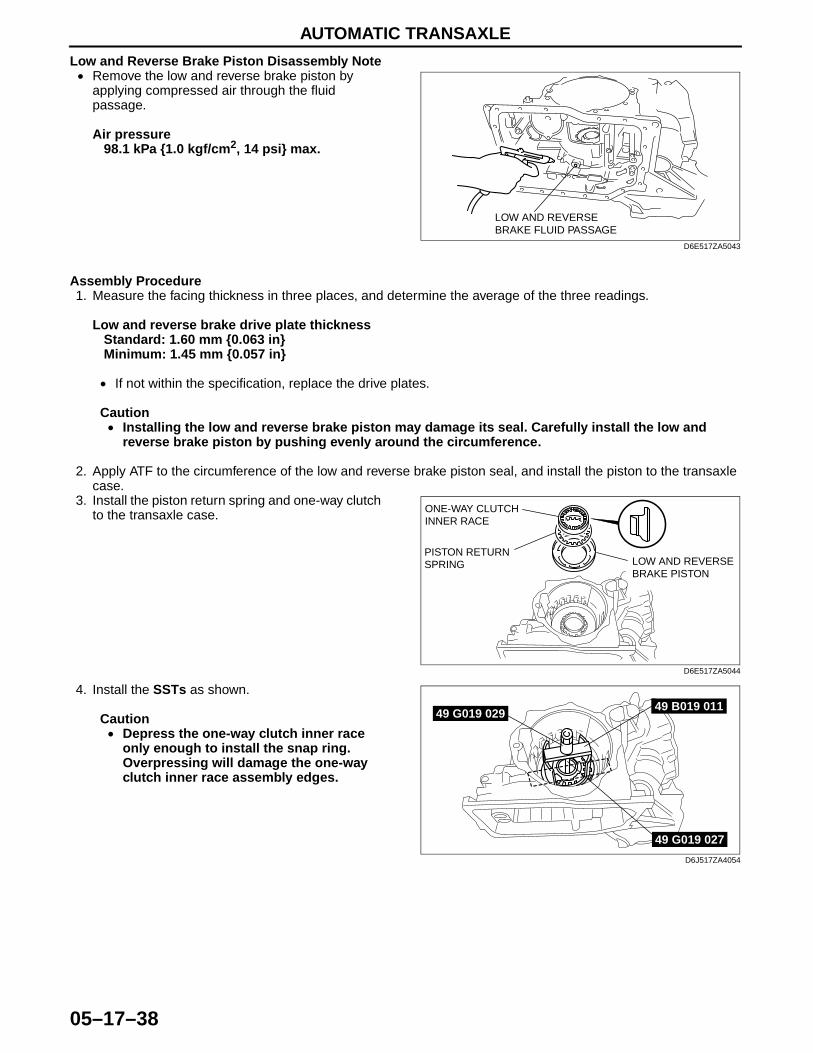
AUTOMATIC TRANSAXLE
05–17–38
Low and Reverse Brake Piston Disassembly Note• Remove the low and reverse brake piston by
applying compressed air through the fluid passage.
Air pressure98.1 kPa {1.0 kgf/cm2, 14 psi} max.
Assembly Procedure1. Measure the facing thickness in three places, and determine the average of the three readings.
Low and reverse brake drive plate thicknessStandard: 1.60 mm {0.063 in}Minimum: 1.45 mm {0.057 in}
• If not within the specification, replace the drive plates.
Caution• Installing the low and reverse brake piston may damage its seal. Carefully install the low and
reverse brake piston by pushing evenly around the circumference.
2. Apply ATF to the circumference of the low and reverse brake piston seal, and install the piston to the transaxle case.
3. Install the piston return spring and one-way clutch to the transaxle case.
4. Install the SSTs as shown.
Caution• Depress the one-way clutch inner race
only enough to install the snap ring.Overpressing will damage the one-way clutch inner race assembly edges.
LOW AND REVERSE BRAKE FLUID PASSAGE
D6E517ZA5043
LOW AND REVERSE BRAKE PISTON
PISTON RETURN SPRING
ONE-WAY CLUTCH INNER RACE
D6E517ZA5044
49 B019 01149 G019 029
49 G019 027
D6J517ZA4054
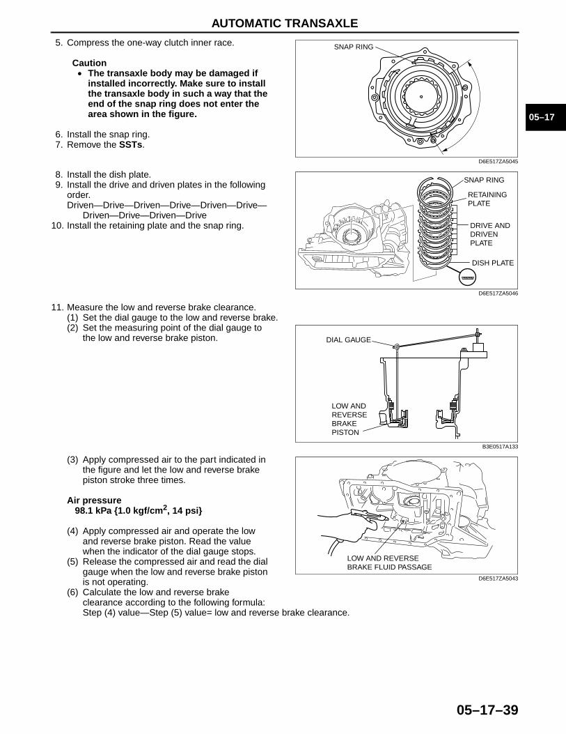
AUTOMATIC TRANSAXLE
05–17–39
05–17
5. Compress the one-way clutch inner race.
Caution• The transaxle body may be damaged if
installed incorrectly. Make sure to install the transaxle body in such a way that the end of the snap ring does not enter the area shown in the figure.
6. Install the snap ring.7. Remove the SSTs.
8. Install the dish plate.9. Install the drive and driven plates in the following
order.Driven—Drive—Driven—Drive—Driven—Drive—
Driven—Drive—Driven—Drive10. Install the retaining plate and the snap ring.
11. Measure the low and reverse brake clearance.(1) Set the dial gauge to the low and reverse brake.(2) Set the measuring point of the dial gauge to
the low and reverse brake piston.
(3) Apply compressed air to the part indicated in the figure and let the low and reverse brake piston stroke three times.
Air pressure98.1 kPa {1.0 kgf/cm2, 14 psi}
(4) Apply compressed air and operate the low and reverse brake piston. Read the value when the indicator of the dial gauge stops.
(5) Release the compressed air and read the dial gauge when the low and reverse brake piston is not operating.
(6) Calculate the low and reverse brake clearance according to the following formula:Step (4) value—Step (5) value= low and reverse brake clearance.
SNAP RING
D6E517ZA5045
SNAP RING
RETAINING PLATE
DISH PLATE
DRIVE AND DRIVEN PLATE
D6E517ZA5046
DIAL GAUGE
LOW AND REVERSE BRAKE PISTON
B3E0517A133
LOW AND REVERSE BRAKE FLUID PASSAGE
D6E517ZA5043
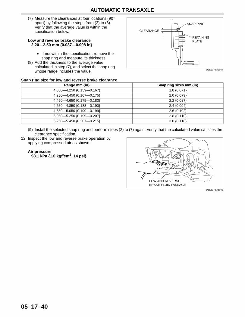
AUTOMATIC TRANSAXLE
05–17–40
(7) Measure the clearances at four locations (90° apart) by following the steps from (3) to (6). Verify that the average value is within the specification below.
Low and reverse brake clearance2.20—2.50 mm {0.087—0.098 in}
• If not within the specification, remove the snap ring and measure its thickness.
(8) Add the thickness to the average value calculated in step (7), and select the snap ring whose range includes the value.
Snap ring size for low and reverse brake clearance
(9) Install the selected snap ring and perform steps (2) to (7) again. Verify that the calculated value satisfies the clearance specification.
12. Inspect the low and reverse brake operation by applying compressed air as shown.
Air pressure98.1 kPa {1.0 kgf/cm2, 14 psi}
End Of Sie
SNAP RING
CLEARANCE
RETAINING PLATE
D6E517ZA5047
Range mm {in} Snap ring sizes mm {in}4.050—4.250 {0.159—0.167} 1.8 {0.071}4.250—4.450 {0.167—0.175} 2.0 {0.079}4.450—4.650 {0.175—0.183} 2.2 {0.087}4.650—4.850 {0.183—0.190} 2.4 {0.094}4.850—5.050 {0.190—0.199} 2.6 {0.102}5.050—5.250 {0.199—0.207} 2.8 {0.110}5.250—5.450 {0.207—0.215} 3.0 {0.118}
LOW AND REVERSE BRAKE FLUID PASSAGE
D6E517ZA5043

AUTOMATIC TRANSAXLE
05–17–41
05–17
DIRECT CLUTCH DISASSEMBLY/ASSEMBLYE6U051719500A18
1. Perform the preinspection before disassembly. (See 05–17–113 Direct Clutch Preinspection.)2. Disassemble in the order indicated in the table. 3. Assemble in the reverse order of disassembly.
.
Needle Bearing Disassembly Note1. Remove the needle bearing using the SST as
shown in the figure.
SST R
9
8
7
5
43
12
6
ATFTF
ATF
ATFTF
SELECTIVE
D6E517ZA5048
1 Needle bearing(See 05–17–41 Needle Bearing Disassembly Note.)
2 Snap ring3 Retaining plate4 Drive and driven plate5 Snap ring
(See 05–17–42 Snap Ring (Direct clutch) Disassembly Note.)
6 Seal plate7 Spring and retainer component8 Direct clutch piston
(See 05–17–42 Direct Clutch Piston Disassembly Note.)
9 Direct clutch drum
49 E032 303
49 F028 202
D6J517ZA4100

AUTOMATIC TRANSAXLE
05–17–42
Snap Ring (Direct clutch) Disassembly Note1. Install the SST as shown.
Caution• Depress the seal plate only enough to
remove the snap ring. Overpressing will damage the seal plate assembly edges.
2. Compress the seal plate.3. Remove the snap ring.4. Remove the SST, then remove the seal plate and
spring and retainer component.
Direct Clutch Piston Disassembly Note1. Set the direct clutch drum onto the transaxle case.2. Remove the direct clutch piston from the direct
clutch drum by applying compressed air through the fluid passage.
Air pressure392—441 kPa {4.0—4.5 kgf/cm2, 57—63 psi}
Assembly Procedure1. Measure the facing thickness in three places and calculate the average value.
Direct clutch drive plate thicknessStandard: 1.80 mm {0.071 in}Minimum: 1.65 mm {0.065 in}
• If not within the specification, replace the drive plates.2. Measure the free length of the spring and inspect
for deformation.
Direct clutch springs and retainer component free length
Standard: 17.2 mm {0.677 in}Minimum: 15.2 mm {0.598 in}
• If not within the specification, replace the spring and retainer.
49 B019 012
PRESS
D6E517ZA5049
DIRECT CLUTCH FLUID PASSAGE
D6E517ZA5050
B3E0517A111
AUTOMATIC TRANSAXLE
05–17–43
05–17
3. Verify that there is airflow when applying compressed air through the fluid passage of direct clutch drum. (four locations)
Air pressure392—441 kPa {4.0—4.5 kgf/cm2, 57—63 psi}
4. Replace the direct clutch drum if damaged or malfunctioning.
5. Install the direct clutch.
Caution• Installing the direct clutch piston may damage its seal. Carefully install the direct clutch piston by
pushing evenly around the circumference.
(1) Apply ATF to the circumference of the direct clutch piston seal, and install the piston in to the direct clutch drum.
(2) Install the spring and retainer.(3) Apply ATF to the seal plate, and install it onto the direct clutch drum.(4) Install the SST as shown.
Caution• Depress the seal plate only enough to
install the snap ring. Overpressing will damage the seal plate assembly edges.
(5) Compress the spring and retainer component and seal plate.
(6) Install the snap ring.(7) Remove the SST.
(8) Install the drive and driven plates in the following order.Driven—Drive—Driven—Driven—Drive
(9) Install the retaining plate.(10)Install the snap ring.
D6J517ZA4181
49 B019 012
PRESS
D6E517ZA5049
SNAP RING
RETAINING PLATE
DRIVE AND DRIVEN PLATE
D6E517ZA5051
AUTOMATIC TRANSAXLE
05–17–44
6. Measure the direct clutch clearance.(1) Install the direct clutch in the transaxle case, and set the dial gauge.(2) Secure the direct clutch by lightly pressing
down with a press or similar tool.
(3) Apply compressed air to the part indicated in the figure and let the direct clutch piston stroke three times.
Air pressure392—441 kPa {4.0—4.5 kgf/cm2, 57—63 psi}
(4) Apply compressed air and operate the direct clutch piston. Read the value when the indicator of the dial gauge stops.
(5) Release the compressed air and read the dial gauge when the direct clutch piston is not operating.
(6) Calculate the direct clutch clearance according to the following formula:step (4) value – step (5) value = direct clutch clearance.
(7) Measure the clearances at four locations (90° apart) by following the steps from (3) to (6). Verify that the average value is within the specification below.
Direct clutch clearanceStandard: 1.10—1.40 mm {0.043—0.055 in}
• If not within the specification, remove the snap ring and measure its thickness.
(8) Add the thickness to the average value calculated in step (7), and select the snap ring whose range includes the value.
Snap ring size for direct clutch clearance
(9) Install the selected snap ring and perform steps (2) to (7) again. Verify that the calculated value satisfies the clearance specification.
RETAININGPLATE
PRESSDIAL GAUGE
D6E517ZA5052
DIRECT CLUTCH FLUID PASSAGE
D6E517ZA5050
SNAP RING
CLEARANCE
RETAINING PLATE
D6E517ZA5053
Range mm {in} Snap ring sizes mm {in}2.424—2.624 {0.096—0.103} 1.2 {0.047}2.624—2.824 {0.104—0.111} 1.4 {0.055}2.824—3.024 {0.112—0.119} 1.6 {0.063}3.024—3.224 {0.120—0.126} 1.8 {0.071}3.224—3.424 {0.127—0.134} 2.0 {0.079}3.424—3.624 {0.135—0.142} 2.2 {0.087}
AUTOMATIC TRANSAXLE
05–17–45
05–17
7. Inspect the direct clutch operation. (1) Install the direct clutch drum to the transaxle case. (2) Inspect the direct clutch operation by applying
compressed air as shown.
Air pressure392—441 kPa {4.0—4.5 kgf/cm2, 57—63 psi}
8. Install the needle bearing using the SST as shown in the figure.
Distance AA: 0—0.5 mm {0—0.02 in}
End Of Sie
DIRECT CLUTCH FLUID PASSAGE
D6E517ZA5050
49 E032 303
49 F028 202
A
D6J517ZA4101
AUTOMATIC TRANSAXLE
05–17–46
REDUCTION BRAKE DISASSEMBLY/ASSEMBLYE6U051719500A19
1. Perform the preinspection before disassembly.(See 05–17–114 Reduction Brake Preinspection.)
2. Disassemble in the order indicated in the table.3. Assemble in the reverse order of disassembly..
Snap Ring Disassembly Note1. Install the SST as shown.
Caution• Depress the spring and retainer
component only enough to remove the snap ring.Overpressing will damage the spring and retainer component assembly edges.
2. Compress the spring and retainer component.3. Remove the snap ring.4. Remove the SST and remove spring and retainer
component.
SSTR 4 5
6
3
1
2
SELECTIVE
D6E517ZA5054
1 Snap ring2 Retaining plate3 Drive and driven plates4 Snap ring
(See 05–17–46 Snap Ring Disassembly Note.)
5 Spring and retainer component6 Reduction brake piston
(See 05–17–47 Reduction Brake Piston Disassembly Note.)
49 B025 003
PRESS
D6J517ZA4107
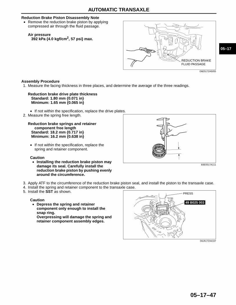
AUTOMATIC TRANSAXLE
05–17–47
05–17
Reduction Brake Piston Disassembly Note• Remove the reduction brake piston by applying
compressed air through the fluid passage.
Air pressure392 kPa {4.0 kgf/cm2, 57 psi} max.
Assembly Procedure1. Measure the facing thickness in three places, and determine the average of the three readings.
Reduction brake drive plate thicknessStandard: 1.80 mm {0.071 in}Minimum: 1.65 mm {0.065 in}
• If not within the specification, replace the drive plates.2. Measure the spring free length.
Reduction brake springs and retainer component free length
Standard: 18.2 mm {0.717 in}Minimum: 16.2 mm {0.638 in}
• If not within the specification, replace the spring and retainer component.
Caution• Installing the reduction brake piston may
damage its seal. Carefully install the reduction brake piston by pushing evenly around the circumference.
3. Apply ATF to the circumference of the reduction brake piston seal, and install the piston to the transaxle case.4. Install the spring and retainer component to the transaxle case.5. Install the SST as shown.
Caution• Depress the spring and retainer
component only enough to install the snap ring.Overpressing will damage the spring and retainer component assembly edges.
REDUCTION BRAKE FLUID PASSAGE
D6E517ZA5055
B3E0517A111
49 B025 003
PRESS
D6J517ZA4107
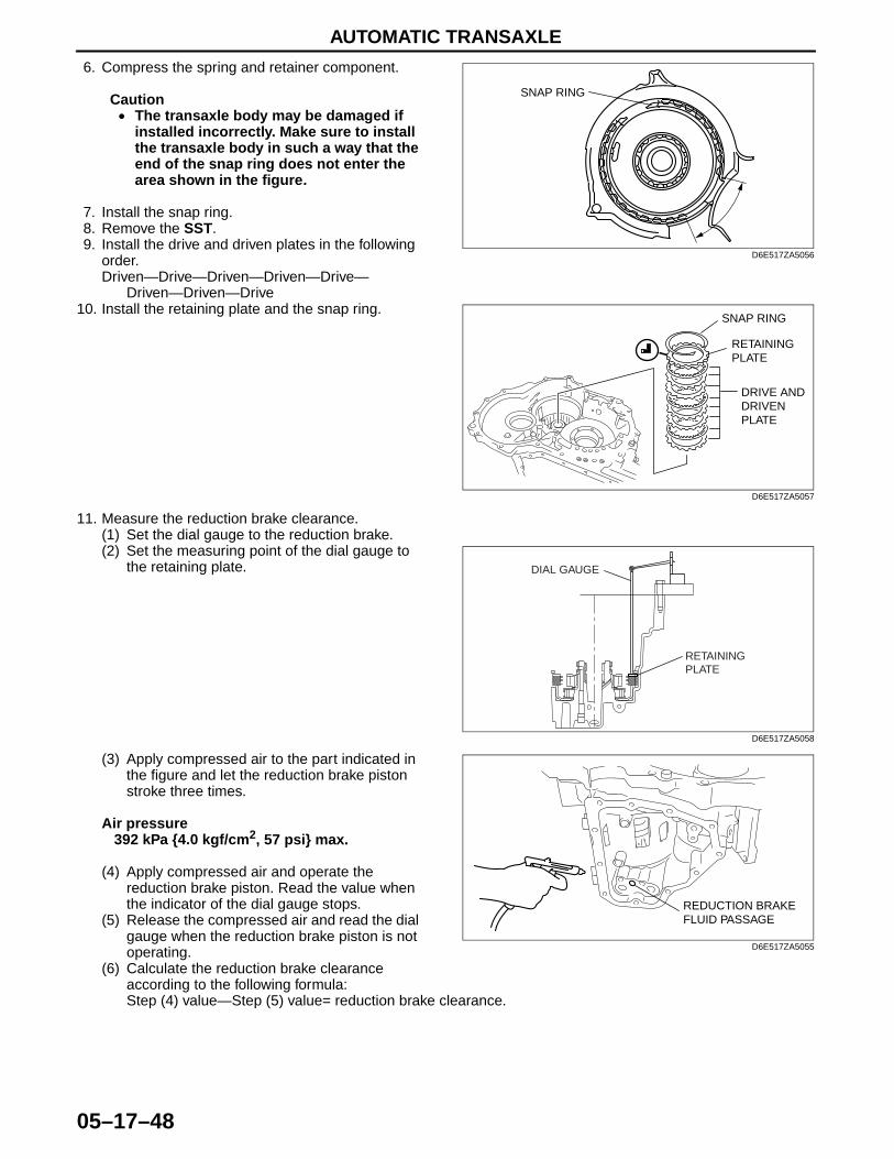
AUTOMATIC TRANSAXLE
05–17–48
6. Compress the spring and retainer component.
Caution• The transaxle body may be damaged if
installed incorrectly. Make sure to install the transaxle body in such a way that the end of the snap ring does not enter the area shown in the figure.
7. Install the snap ring.8. Remove the SST.9. Install the drive and driven plates in the following
order.Driven—Drive—Driven—Driven—Drive—
Driven—Driven—Drive10. Install the retaining plate and the snap ring.
11. Measure the reduction brake clearance.(1) Set the dial gauge to the reduction brake.(2) Set the measuring point of the dial gauge to
the retaining plate.
(3) Apply compressed air to the part indicated in the figure and let the reduction brake piston stroke three times.
Air pressure392 kPa {4.0 kgf/cm2, 57 psi} max.
(4) Apply compressed air and operate the reduction brake piston. Read the value when the indicator of the dial gauge stops.
(5) Release the compressed air and read the dial gauge when the reduction brake piston is not operating.
(6) Calculate the reduction brake clearance according to the following formula:Step (4) value—Step (5) value= reduction brake clearance.
SNAP RING
D6E517ZA5056
SNAP RING
RETAINING PLATE
DRIVE AND DRIVEN PLATE
D6E517ZA5057
RETAININGPLATE
DIAL GAUGE
D6E517ZA5058
REDUCTION BRAKE FLUID PASSAGE
D6E517ZA5055

AUTOMATIC TRANSAXLE
05–17–49
05–17
(7) Measure the clearances at four locations (90° apart) by following the steps from (3) to (6). Verify that the average value is within the specification below.
Reduction brake clearance1.50—1.80 mm {0.059—0.070 in}
• If not within the specification, remove the snap ring and measure its thickness.
(8) Add the thickness to the average value calculated in step (7), and select the snap ring whose range includes the value.
Snap ring size for reduction brake clearance
(9) Install the selected snap ring and perform steps (2) to (7) again. Verify that the calculated value satisfies the clearance specification.
12. Inspect the reduction brake operation by applying compressed air as shown.
Air pressure392 kPa {4.0 kgf/cm2, 57 psi} max.
End Of Sie
SNAP RING
CLEARANCERETAINING PLATE
D6E517ZA5059
Range mm {in} Snap ring sizes mm {in}2.920—3.120 {0.115—0.122} 1.2 {0.047}3.120—3.320 {0.123—0.130} 1.4 {0.055}3.320—3.520 {0.131—0.138} 1.6 {0.063}3.520—3.720 {0.139—0.146} 1.8 {0.071}3.720—3.920 {0.147—0.154} 2.0 {0.079}3.920—4.120 {0.155—0.162} 2.2 {0.087}
REDUCTION BRAKE FLUID PASSAGE
D6E517ZA5055
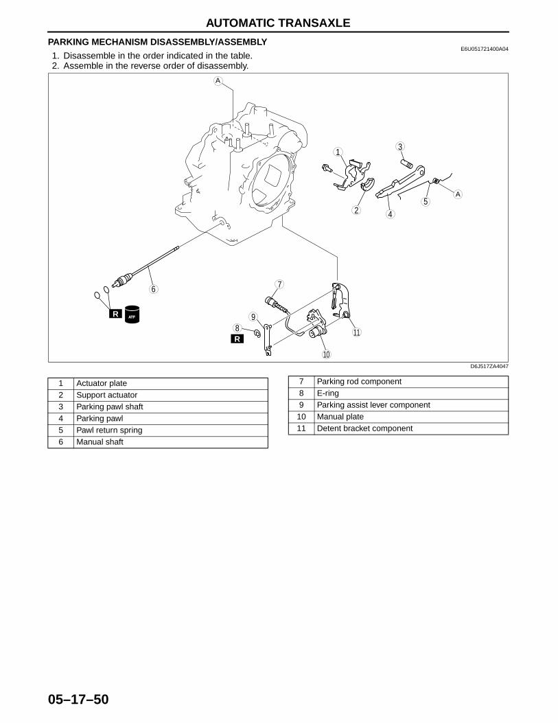
AUTOMATIC TRANSAXLE
05–17–50
PARKING MECHANISM DISASSEMBLY/ASSEMBLYE6U051721400A04
1. Disassemble in the order indicated in the table.2. Assemble in the reverse order of disassembly.
98
7
54
31
2
10
6
11
R
R
ATF
A
A
D6J517ZA4047
1 Actuator plate2 Support actuator3 Parking pawl shaft4 Parking pawl5 Pawl return spring6 Manual shaft
7 Parking rod component8 E-ring9 Parking assist lever component
10 Manual plate11 Detent bracket component
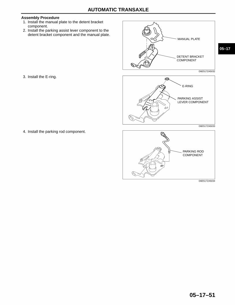
AUTOMATIC TRANSAXLE
05–17–51
05–17
Assembly Procedure1. Install the manual plate to the detent bracket
component.2. Install the parking assist lever component to the
detent bracket component and the manual plate.
3. Install the E-ring.
4. Install the parking rod component.End Of Sie
MANUAL PLATE
DETENT BRACKET COMPONENT
D6E517ZA5032
E-RING
PARKING ASSIST LEVER COMPONENT
D6E517ZA5033
PARKING ROD COMPONENT
D6E517ZA5034

AUTOMATIC TRANSAXLE
05–17–52
SECONDARY GEAR AND OUTPUT GEAR DISASSEMBLY/ASSEMBLYE6U051719204A02
1. Remove the following parts. (See 05–17–2 AUTOMATIC TRANSAXLE DISASSEMBLY.)• Torque converter• Oil pump• Converter housing• Differential
2. Disassemble in the order indicated in the table.3. Assemble in the reverse order of disassembly.
Lock nut Disassembly Note1. Rotate the manual shaft to the P position.
2. Knock the crimped portion of the locknut outward by using a small chisel and a hammer.
3. Remove the lock nut.
1Lock nut(See 05–17–52 Lock nut Disassembly Note.)(See 05–17–53 Lock nut Assembly Note.)
2
Inner race(See 05–17–53 Output gear And Inner Race Disassembly Note.)(See 05–17–53 Output gear And Inner Race Assembly Note.)
3
Output gear(See 05–17–53 Output gear And Inner Race Disassembly Note.)(See 05–17–53 Output gear And Inner Race Assembly Note.)
4 Secondary gear component
1
2
3
4
SST
R SST
SST
D6J517ZA4097
PR N D, M
CONVERTERHOUSINGSIDE
MANUAL SHAFT
D6E517AW5007
D6J517ZA4085

AUTOMATIC TRANSAXLE
05–17–53
05–17
Output gear And Inner Race Disassembly Note1. Remove the output gear component. (See 05–17–2 AUTOMATIC TRANSAXLE DISASSEMBLY.)2. Remove the output gear and inner race to the
secondary gear component using the SST.
Output gear And Inner Race Assembly Note1. Install the output gear to the secondary gear
component using the SST.
Press-in force20 kN {204 kgf, 450 lbf}
2. Install the inner race to the secondary gear component using the SST.
Press-in force20 kN {204 kgf, 450 lbf}
Lock nut Assembly Note1. Install the following parts. (See 05–17–2 AUTOMATIC TRANSAXLE DISASSEMBLY.)
• Pawl return spring• Parking pawl• Parking pawl shaft• Support actuator• Actuator plate
2. Rotate the manual shaft to the P position.3. Install the locknut.
Tightening torque100—120 N·m {10.2—12.2 kgf·m, 74—88
ft·lbf}
49 E032 303
49 0187 520
PRESS
D6E517ZA5035
49 F401 331
49 F401 337A
PRESS
D6E517ZA5036
49 F401 331
49 F401 337A
PRESS
D6E517ZA5037
PR N D, M
CONVERTERHOUSINGSIDE
MANUAL SHAFT
D6E517AW5007
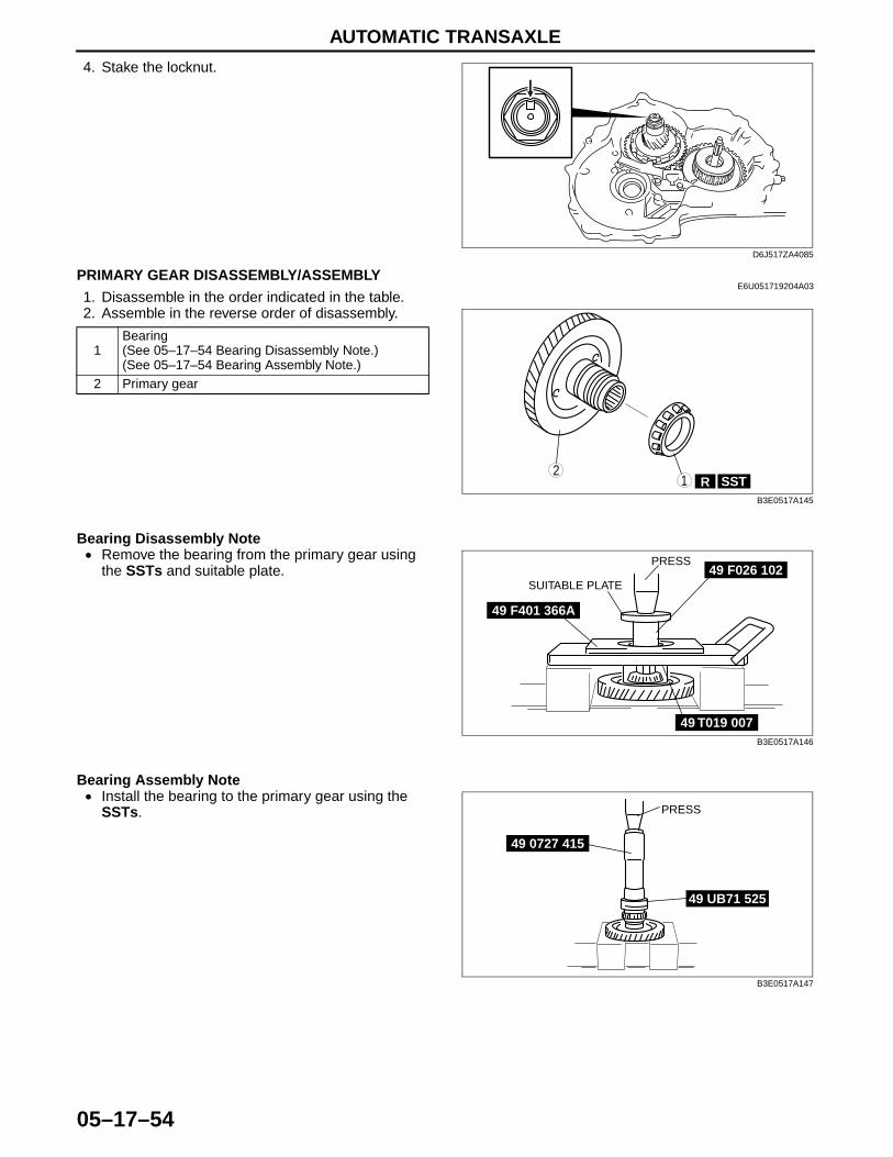
AUTOMATIC TRANSAXLE
05–17–54
4. Stake the locknut.End Of Sie
PRIMARY GEAR DISASSEMBLY/ASSEMBLYE6U051719204A03
1. Disassemble in the order indicated in the table.2. Assemble in the reverse order of disassembly.
Bearing Disassembly Note• Remove the bearing from the primary gear using
the SSTs and suitable plate.
Bearing Assembly Note• Install the bearing to the primary gear using the
SSTs.End Of Sie
D6J517ZA4085
1Bearing(See 05–17–54 Bearing Disassembly Note.)(See 05–17–54 Bearing Assembly Note.)
2 Primary gear
SSTR12
B3E0517A145
49 F026 102
49 T019 007
PRESS
SUITABLE PLATE
49 F401 366A
B3E0517A146
49 0727 415
49 UB71 525
PRESS
B3E0517A147
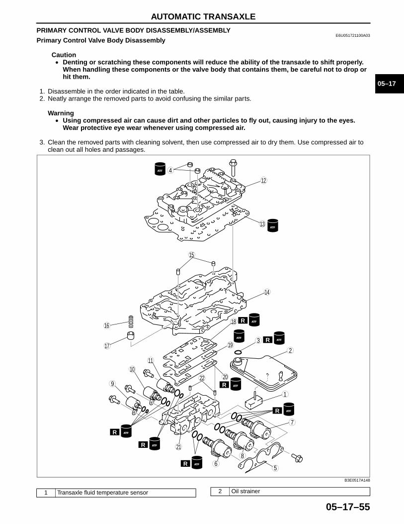
AUTOMATIC TRANSAXLE
05–17–55
05–17
PRIMARY CONTROL VALVE BODY DISASSEMBLY/ASSEMBLYE6U051721100A03
Primary Control Valve Body Disassembly
Caution• Denting or scratching these components will reduce the ability of the transaxle to shift properly.
When handling these components or the valve body that contains them, be careful not to drop or hit them.
1. Disassemble in the order indicated in the table.2. Neatly arrange the removed parts to avoid confusing the similar parts.
Warning• Using compressed air can cause dirt and other particles to fly out, causing injury to the eyes.
Wear protective eye wear whenever using compressed air.
3. Clean the removed parts with cleaning solvent, then use compressed air to dry them. Use compressed air to clean out all holes and passages.
ATF
ATF
ATF
ATF
ATF
ATF
ATF
ATF
ATF
ATF
R
R
R
R
R
R
R
8
7
5
4
3
1
2
6
9
10
19
18
17
15
16
14
13
11
12
2022
21
B3E0517A148
1 Transaxle fluid temperature sensor 2 Oil strainer
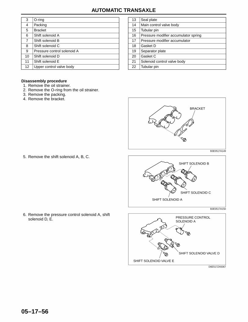
AUTOMATIC TRANSAXLE
05–17–56
Disassembly procedure1. Remove the oil strainer.2. Remove the O-ring from the oil strainer.3. Remove the packing.4. Remove the bracket.
5. Remove the shift solenoid A, B, C.
6. Remove the pressure control solenoid A, shift solenoid D, E.
3 O-ring4 Packing5 Bracket6 Shift solenoid A7 Shift solenoid B8 Shift solenoid C9 Pressure control solenoid A
10 Shift solenoid D11 Shift solenoid E12 Upper control valve body
13 Seal plate14 Main control valve body15 Tubular pin16 Pressure modifier accumulator spring17 Pressure modifier accumulator18 Gasket D19 Separator plate20 Gasket C21 Solenoid control valve body22 Tubular pin
BRACKET
B3E0517A149
SHIFT SOLENOID B
SHIFT SOLENOID C
SHIFT SOLENOID A
B3E0517A150
SHIFT SOLENOID VALVE D
PRESSURE CONTROL SOLENOID A
SHIFT SOLENOID VALVE E
D6E517ZA5067
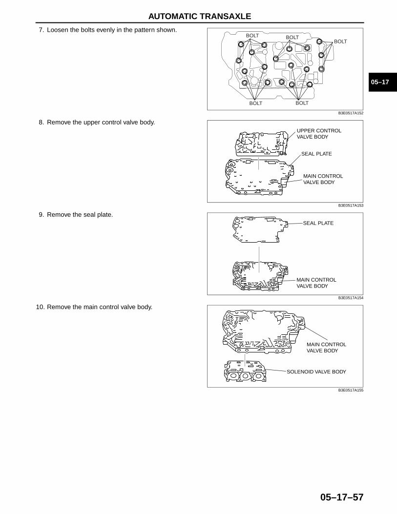
AUTOMATIC TRANSAXLE
05–17–57
05–17
7. Loosen the bolts evenly in the pattern shown.
8. Remove the upper control valve body.
9. Remove the seal plate.
10. Remove the main control valve body.
BOLT
BOLT BOLT
BOLTBOLT
B3E0517A152
SEAL PLATE
UPPER CONTROL VALVE BODY
MAIN CONTROL VALVE BODY
B3E0517A153
SEAL PLATE
MAIN CONTROL VALVE BODY
B3E0517A154
MAIN CONTROL VALVE BODY
SOLENOID VALVE BODY
B3E0517A155

AUTOMATIC TRANSAXLE
05–17–58
11. Remove the tubular pins, pressure modifier accumulator spring and pressure modifier accumulator from the main control valve body.
12. Remove the gasket D, separator plate and gasket C.
13. Remove the tubular pins.
TUBELAR PIN PRESSURE MODIFIER ACCUMULATOR SPRING
PRESSURE MODIFIER ACCUMULATOR
B3E0517A156
GASKET D
GASKET C
SEPARATOR PLATE
B3E0517A157
TUBULAR PIN
SOLENOID VALVE BODY
B3E0517A158
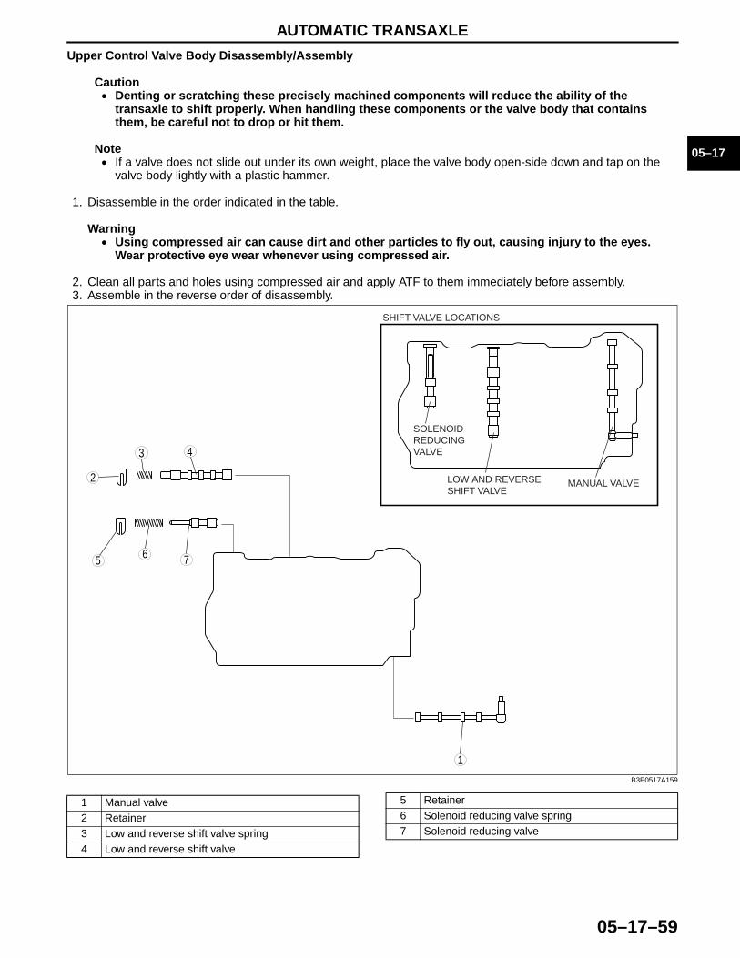
AUTOMATIC TRANSAXLE
05–17–59
05–17
Upper Control Valve Body Disassembly/Assembly
Caution• Denting or scratching these precisely machined components will reduce the ability of the
transaxle to shift properly. When handling these components or the valve body that contains them, be careful not to drop or hit them.
Note• If a valve does not slide out under its own weight, place the valve body open-side down and tap on the
valve body lightly with a plastic hammer.
1. Disassemble in the order indicated in the table.
Warning• Using compressed air can cause dirt and other particles to fly out, causing injury to the eyes.
Wear protective eye wear whenever using compressed air.
2. Clean all parts and holes using compressed air and apply ATF to them immediately before assembly.3. Assemble in the reverse order of disassembly.
75
43
1
2
6
SOLENOID REDUCING VALVE
LOW AND REVERSE SHIFT VALVE
MANUAL VALVE
SHIFT VALVE LOCATIONS
B3E0517A159
1 Manual valve2 Retainer3 Low and reverse shift valve spring4 Low and reverse shift valve
5 Retainer6 Solenoid reducing valve spring7 Solenoid reducing valve

AUTOMATIC TRANSAXLE
05–17–60
Assembly procedure1. Measure the spring free length.
Primary control valve body spring (standard)
• If not as specified, replace the springs.2. Install the solenoid reducing valve, solenoid reducing valve spring and retainer.3. Install the low and reverse shift valve, low and
reverse shift valve spring and retainer.
4. Install the manual valve.
Main Control Valve Body Disassembly/Assembly
Caution• Denting or scratching these precisely machined components will reduce the ability of the
transaxle to shift properly. When handling these components or the valve body that contains them be careful not to drop or hit them.
Note• If a valve does not slide out under its own weight, place the valve body open-side down and tap on the
valve body lightly with a plastic hammer.
1. Disassemble in the order indicated in the table.
Warning• Using compressed air can cause dirt and other particles to fly out, causing injury to the eyes.
Wear protective eye wear whenever using compressed air.
2. Clean all parts and holes using compressed air and apply ATF to them immediately before assembly.
Item Outer diametermm {in}
Free lengthmm {in} No. of coils Wire diameter
mm {in}Low and reverse shift valve spring 8.7 {0.343} 31.3 {1.232} 9.0 0.8 {0.031}
Solenoid reducing valve spring 8.7 {0.343} 44.2 {1.740} 16.0 1.1 {0.043}
SOLENOID REDUCING VALVE
LOW AND REVERSE SHIFT VALVE
B3E0517A160
B3E0517A161
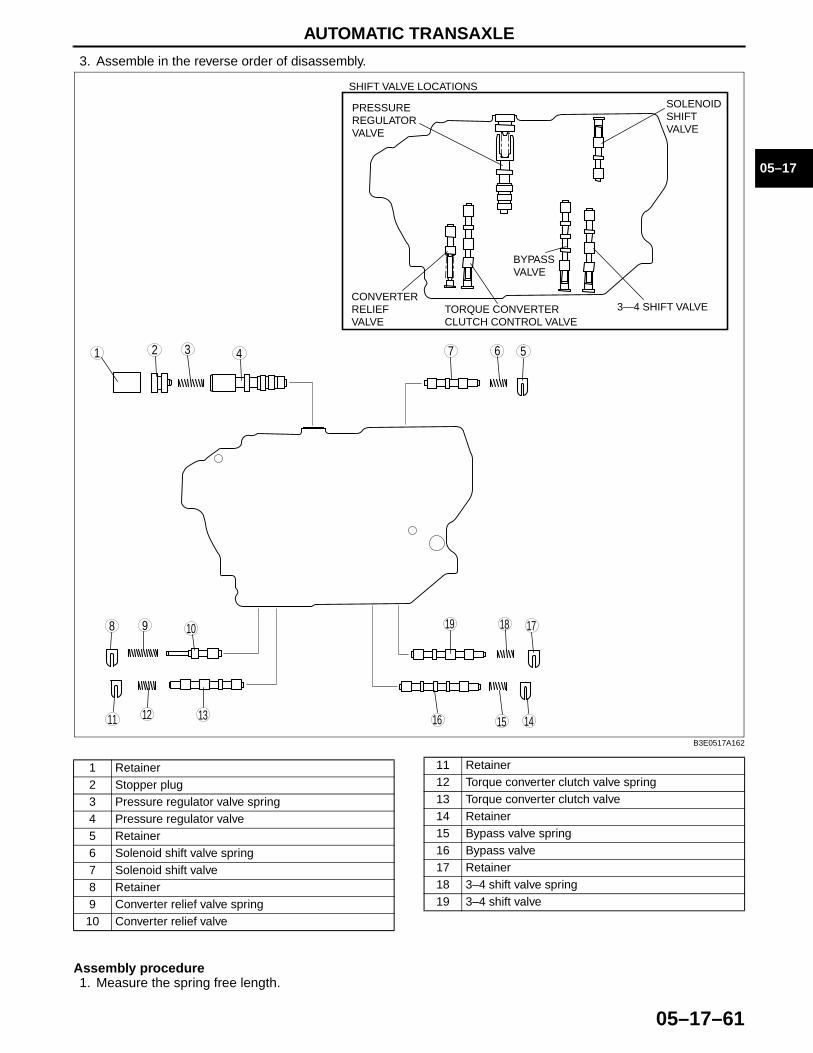
AUTOMATIC TRANSAXLE
05–17–61
05–17
3. Assemble in the reverse order of disassembly.
Assembly procedure1. Measure the spring free length.
98
7 5431 2
10 19 18 17
1516 141311 12
6
SOLENOID SHIFT VALVE
3—4 SHIFT VALVE
BYPASS VALVE
SHIFT VALVE LOCATIONS
PRESSURE REGULATOR VALVE
CONVERTER RELIEF VALVE
TORQUE CONVERTER CLUTCH CONTROL VALVE
B3E0517A162
1 Retainer2 Stopper plug3 Pressure regulator valve spring4 Pressure regulator valve5 Retainer6 Solenoid shift valve spring7 Solenoid shift valve8 Retainer9 Converter relief valve spring10 Converter relief valve
11 Retainer12 Torque converter clutch valve spring13 Torque converter clutch valve14 Retainer15 Bypass valve spring16 Bypass valve17 Retainer18 3–4 shift valve spring19 3–4 shift valve
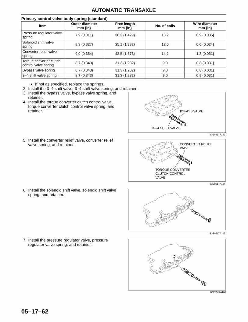
AUTOMATIC TRANSAXLE
05–17–62
Primary control valve body spring (standard)
• If not as specified, replace the springs.2. Install the 3–4 shift valve, 3–4 shift valve spring, and retainer.3. Install the bypass valve, bypass valve spring, and
retainer.4. Install the torque converter clutch control valve,
torque converter clutch control valve spring, and retainer.
5. Install the converter relief valve, converter relief valve spring, and retainer.
6. Install the solenoid shift valve, solenoid shift valve spring, and retainer.
7. Install the pressure regulator valve, pressure regulator valve spring, and retainer.
Item Outer diametermm {in}
Free lengthmm {in} No. of coils Wire diameter
mm {in}Pressure regulator valve spring 7.9 {0.311} 36.3 {1.429} 13.2 0.9 {0.035}
Solenoid shift valve spring 8.3 {0.327} 35.1 {1.382} 12.0 0.6 {0.024}
Converter relief valve spring 9.0 {0.354} 42.5 {1.673} 14.2 1.3 {0.051}
Torque converter clutch control valve spring 8.7 {0.343} 31.3 {1.232} 9.0 0.8 {0.031}
Bypass valve spring 8.7 {0.343} 31.3 {1.232} 9.0 0.8 {0.031}3–4 shift valve spring 8.7 {0.343} 31.3 {1.232} 9.0 0.8 {0.031}
3—4 SHIFT VALVE
BYPASS VALVE
B3E0517A163
TORQUE CONVERTER CLUTCH CONTROL VALVE
CONVERTER RELIEF VALVE
B3E0517A164
B3E0517A165
B3E0517A166

AUTOMATIC TRANSAXLE
05–17–63
05–17
Primary Control Valve Body Assembly1. Verify that all parts are clean and free of dust and other small particles.2. Apply ATF to all parts.3. Assemble in the reverse order of disassembly.
ATF
ATF
ATF
ATF
ATF
ATF
ATF
R
R
R
R
R
R
R
R
32
7
8
5
1
4
96
13
14
10
11
12
19
20
22
17
16
18
15
21
7.8—10.8 N·m {80—110 kgf·cm, 69—95.5 in·lbf}
7.8—10.8 N·m {80—110 kgf·cm, 69—95.5 in·lbf}
7.8—10.8 N·m {80—110 kgf·cm, 69—95.5 in·lbf}
B3E0517A167
1 Solenoid control valve body2 Tubular pin3 Gasket C4 Separator plate5 Gasket D6 Main control valve body7 Pressure modifier accumulator spring8 Pressure modifier accumulator9 Tubular pin10 Seal plate11 Upper control valve body
12 Shift solenoid E13 Shift solenoid D14 Pressure control solenoid A15 Shift solenoid C16 Shift solenoid B17 Shift solenoid A18 Bracket19 Packing20 O-ring21 Oil strainer22 Transaxle fluid temperature sensor
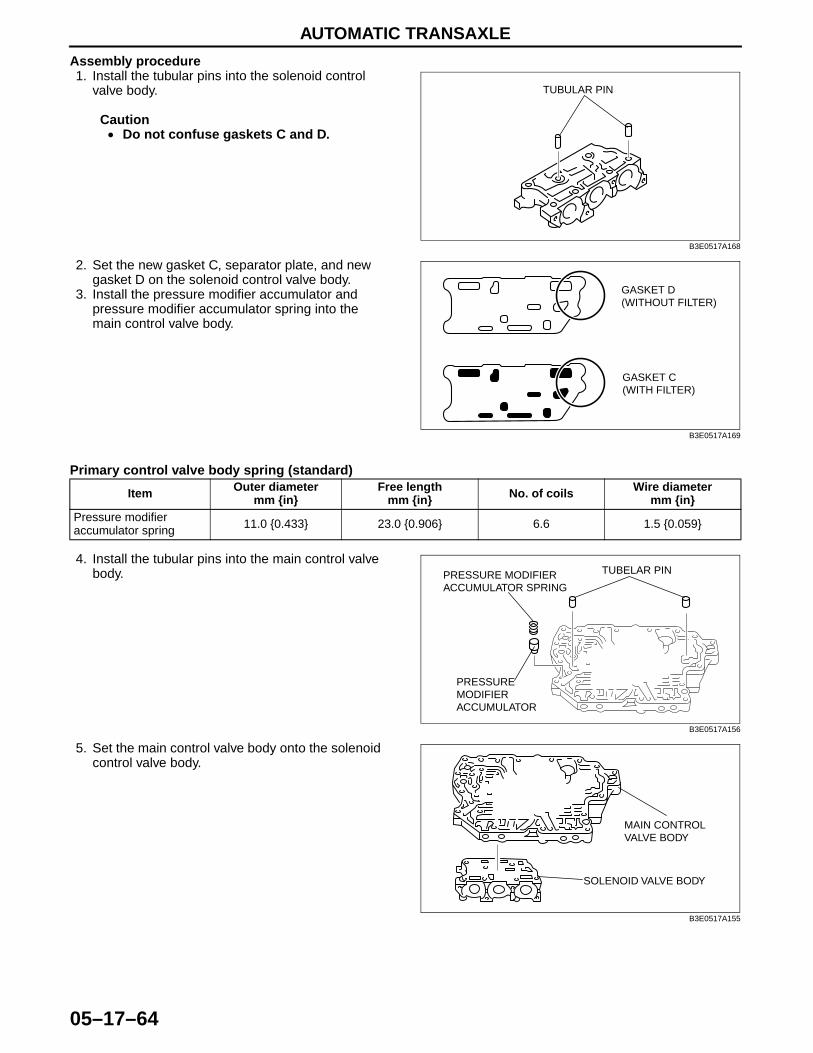
AUTOMATIC TRANSAXLE
05–17–64
Assembly procedure1. Install the tubular pins into the solenoid control
valve body.
Caution• Do not confuse gaskets C and D.
2. Set the new gasket C, separator plate, and new gasket D on the solenoid control valve body.
3. Install the pressure modifier accumulator and pressure modifier accumulator spring into the main control valve body.
Primary control valve body spring (standard)
4. Install the tubular pins into the main control valve body.
5. Set the main control valve body onto the solenoid control valve body.
TUBULAR PIN
B3E0517A168
GASKET D (WITHOUT FILTER)
GASKET C (WITH FILTER)
B3E0517A169
Item Outer diametermm {in}
Free lengthmm {in} No. of coils Wire diameter
mm {in}Pressure modifier accumulator spring 11.0 {0.433} 23.0 {0.906} 6.6 1.5 {0.059}
TUBELAR PIN PRESSURE MODIFIER ACCUMULATOR SPRING
PRESSURE MODIFIER ACCUMULATOR
B3E0517A156
MAIN CONTROL VALVE BODY
SOLENOID VALVE BODY
B3E0517A155
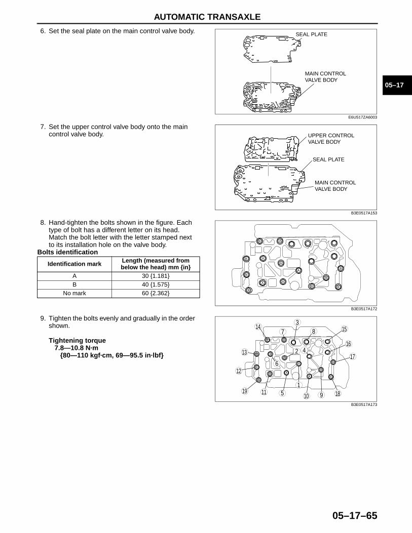
AUTOMATIC TRANSAXLE
05–17–65
05–17
6. Set the seal plate on the main control valve body.
7. Set the upper control valve body onto the main control valve body.
8. Hand-tighten the bolts shown in the figure. Each type of bolt has a different letter on its head. Match the bolt letter with the letter stamped next to its installation hole on the valve body.
Bolts identification
9. Tighten the bolts evenly and gradually in the order shown.
Tightening torque7.8—10.8 N·m
{80—110 kgf·cm, 69—95.5 in·lbf}
Identification mark Length (measured from below the head) mm {in}
A 30 {1.181}B 40 {1.575}
No mark 60 {2.362}
SEAL PLATE
MAIN CONTROL VALVE BODY
E6U517ZA6003
SEAL PLATE
UPPER CONTROL VALVE BODY
MAIN CONTROL VALVE BODY
B3E0517A153
A
A
A
A
AA
B
B
B
BB
B
B
B
B3E0517A172
9
87
5
4
3
1019 18
17
15
16
14
13
11
126
1
2
B3E0517A173
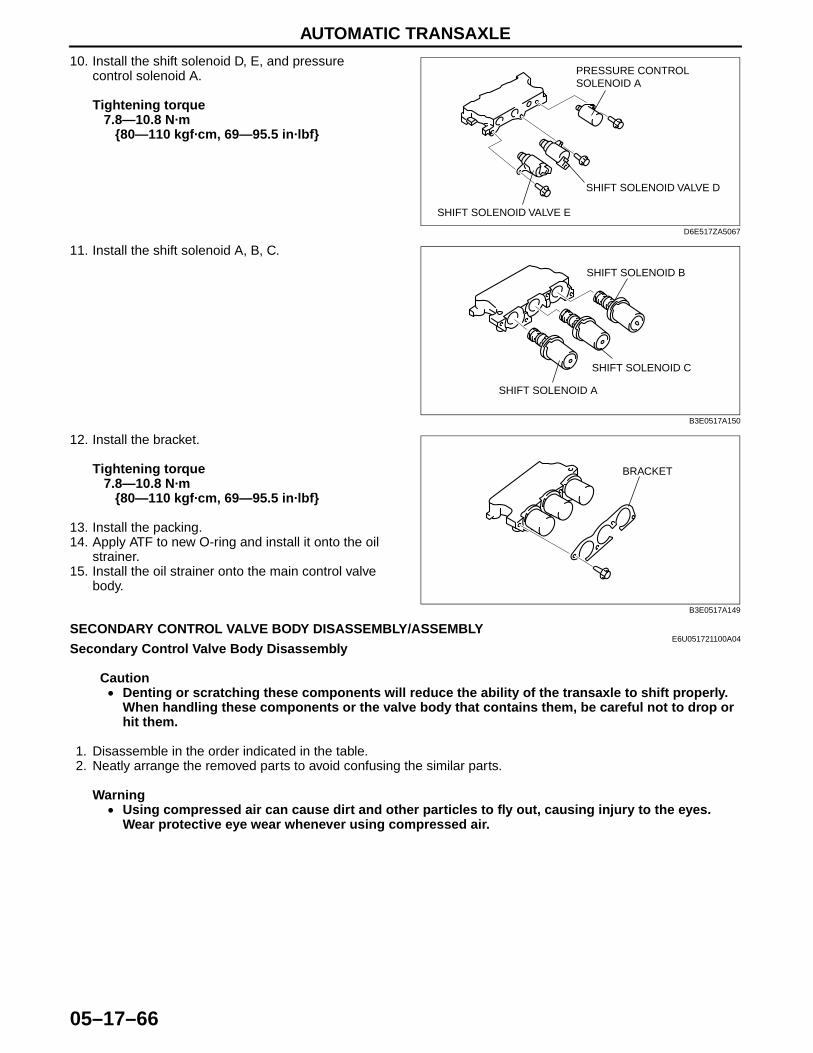
AUTOMATIC TRANSAXLE
05–17–66
10. Install the shift solenoid D, E, and pressure control solenoid A.
Tightening torque7.8—10.8 N·m
{80—110 kgf·cm, 69—95.5 in·lbf}
11. Install the shift solenoid A, B, C.
12. Install the bracket.
Tightening torque7.8—10.8 N·m
{80—110 kgf·cm, 69—95.5 in·lbf}
13. Install the packing.14. Apply ATF to new O-ring and install it onto the oil
strainer.15. Install the oil strainer onto the main control valve
body.End Of Sie
SECONDARY CONTROL VALVE BODY DISASSEMBLY/ASSEMBLYE6U051721100A04
Secondary Control Valve Body Disassembly
Caution• Denting or scratching these components will reduce the ability of the transaxle to shift properly.
When handling these components or the valve body that contains them, be careful not to drop or hit them.
1. Disassemble in the order indicated in the table.2. Neatly arrange the removed parts to avoid confusing the similar parts.
Warning• Using compressed air can cause dirt and other particles to fly out, causing injury to the eyes.
Wear protective eye wear whenever using compressed air.
SHIFT SOLENOID VALVE D
PRESSURE CONTROL SOLENOID A
SHIFT SOLENOID VALVE E
D6E517ZA5067
SHIFT SOLENOID B
SHIFT SOLENOID C
SHIFT SOLENOID A
B3E0517A150
BRACKET
B3E0517A149
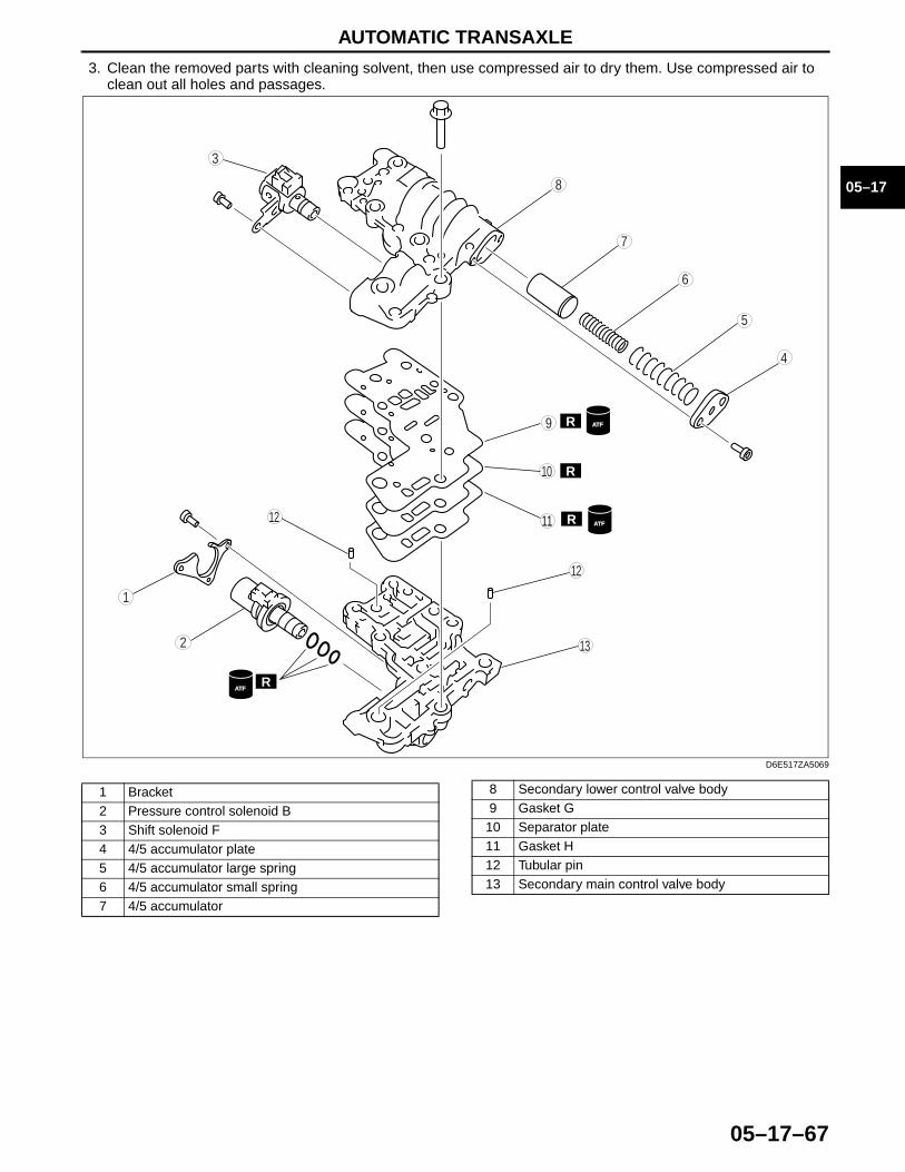
AUTOMATIC TRANSAXLE
05–17–67
05–17
3. Clean the removed parts with cleaning solvent, then use compressed air to dry them. Use compressed air to clean out all holes and passages.
9
8
7
5
4
3
10
13
11
12
6
1
2
R
R
R
R
12ATF
ATF
ATF
D6E517ZA5069
1 Bracket2 Pressure control solenoid B3 Shift solenoid F4 4/5 accumulator plate5 4/5 accumulator large spring6 4/5 accumulator small spring7 4/5 accumulator
8 Secondary lower control valve body9 Gasket G
10 Separator plate11 Gasket H12 Tubular pin13 Secondary main control valve body
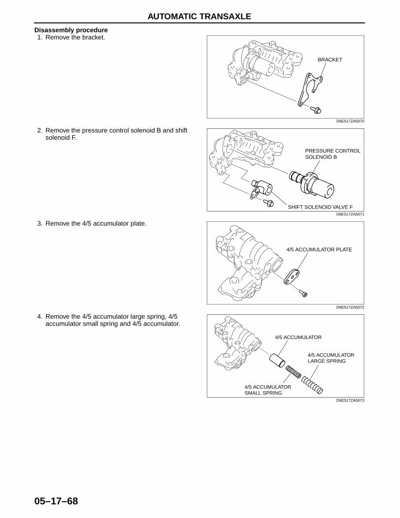
AUTOMATIC TRANSAXLE
05–17–68
Disassembly procedure1. Remove the bracket.
2. Remove the pressure control solenoid B and shift solenoid F.
3. Remove the 4/5 accumulator plate.
4. Remove the 4/5 accumulator large spring, 4/5 accumulator small spring and 4/5 accumulator.
BRACKET
D6E517ZA5070
SHIFT SOLENOID VALVE F
PRESSURE CONTROL SOLENOID B
D6E517ZA5071
4/5 ACCUMULATOR PLATE
D6E517ZA5072
4/5 ACCUMULATOR LARGE SPRING
4/5 ACCUMULATOR
4/5 ACCUMULATOR SMALL SPRING
D6E517ZA5073
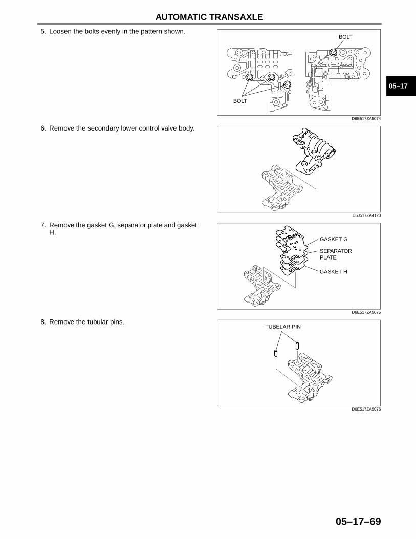
AUTOMATIC TRANSAXLE
05–17–69
05–17
5. Loosen the bolts evenly in the pattern shown.
6. Remove the secondary lower control valve body.
7. Remove the gasket G, separator plate and gasket H.
8. Remove the tubular pins.
BOLT
BOLT
D6E517ZA5074
D6J517ZA4120
GASKET G
GASKET H
SEPARATOR PLATE
D6E517ZA5075
TUBELAR PIN
D6E517ZA5076
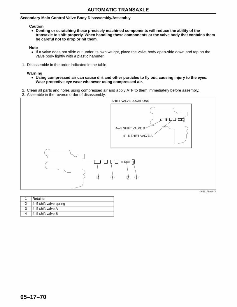
AUTOMATIC TRANSAXLE
05–17–70
Secondary Main Control Valve Body Disassembly/Assembly
Caution• Denting or scratching these precisely machined components will reduce the ability of the
transaxle to shift properly. When handling these components or the valve body that contains them be careful not to drop or hit them.
Note• If a valve does not slide out under its own weight, place the valve body open-side down and tap on the
valve body lightly with a plastic hammer.
1. Disassemble in the order indicated in the table.
Warning• Using compressed air can cause dirt and other particles to fly out, causing injury to the eyes.
Wear protective eye wear whenever using compressed air.
2. Clean all parts and holes using compressed air and apply ATF to them immediately before assembly.3. Assemble in the reverse order of disassembly.
1 Retainer2 4–5 shift valve spring3 4–5 shift valve A4 4–5 shift valve B
4 3 12
4—5 SHIFT VALVE A
SHIFT VALVE LOCATIONS
4—5 SHIFT VALVE B
D6E517ZA5077
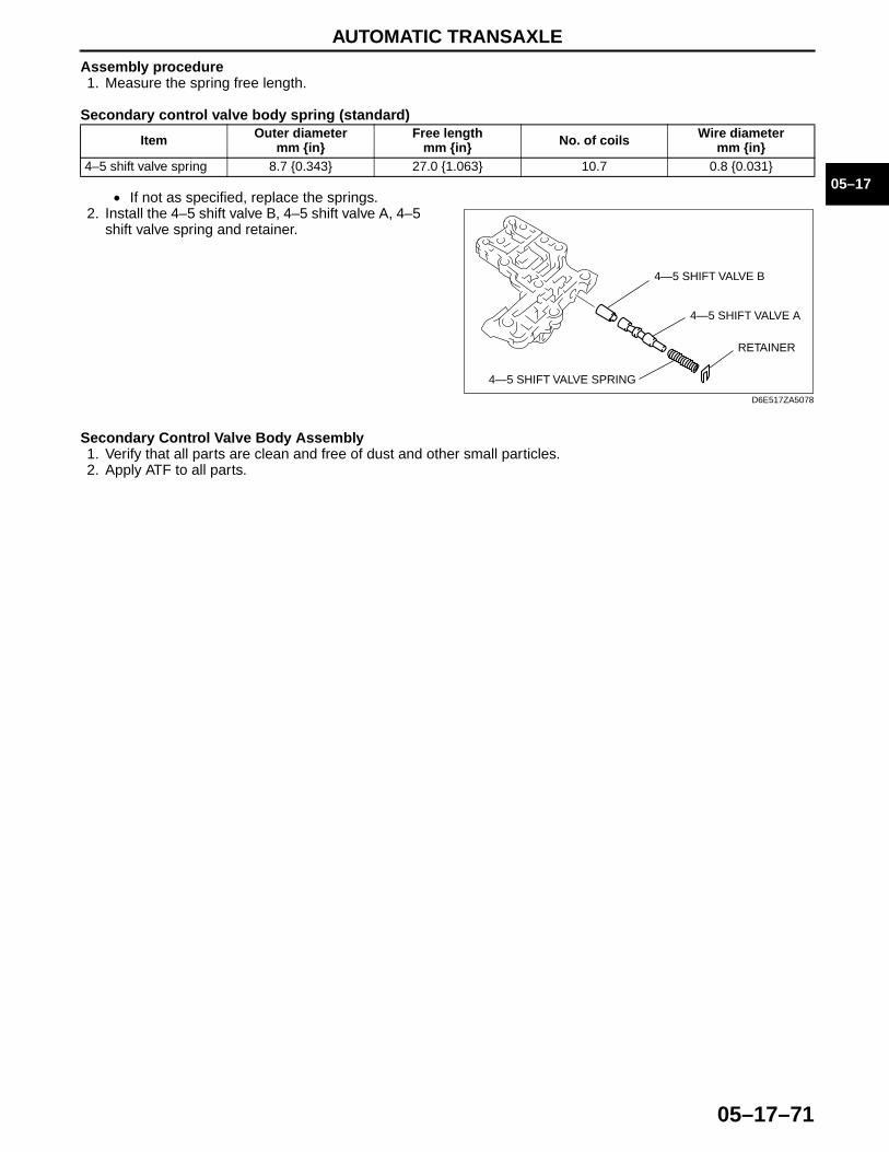
AUTOMATIC TRANSAXLE
05–17–71
05–17
Assembly procedure1. Measure the spring free length.
Secondary control valve body spring (standard)
• If not as specified, replace the springs.2. Install the 4–5 shift valve B, 4–5 shift valve A, 4–5
shift valve spring and retainer.
Secondary Control Valve Body Assembly1. Verify that all parts are clean and free of dust and other small particles.2. Apply ATF to all parts.
Item Outer diametermm {in}
Free lengthmm {in} No. of coils Wire diameter
mm {in}4–5 shift valve spring 8.7 {0.343} 27.0 {1.063} 10.7 0.8 {0.031}
4—5 SHIFT VALVE A
4—5 SHIFT VALVE B
4—5 SHIFT VALVE SPRING
RETAINER
D6E517ZA5078
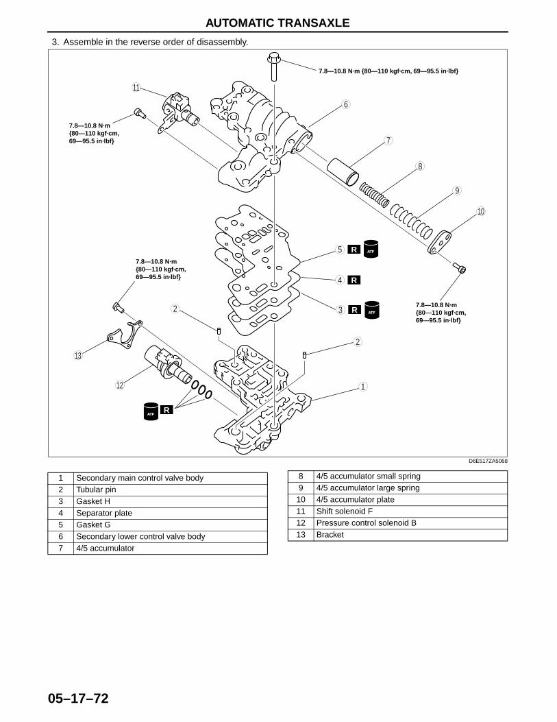
AUTOMATIC TRANSAXLE
05–17–72
3. Assemble in the reverse order of disassembly.
9
8
7
5
4
3
10
13
11
12
6
1
2
R
R
R
R
2 ATF
ATF
ATF
7.8—10.8 N·m {80—110 kgf·cm, 69—95.5 in·lbf}
7.8—10.8 N·m {80—110 kgf·cm, 69—95.5 in·lbf}
7.8—10.8 N·m {80—110 kgf·cm, 69—95.5 in·lbf}
7.8—10.8 N·m {80—110 kgf·cm, 69—95.5 in·lbf}
D6E517ZA5068
1 Secondary main control valve body2 Tubular pin3 Gasket H4 Separator plate5 Gasket G6 Secondary lower control valve body7 4/5 accumulator
8 4/5 accumulator small spring9 4/5 accumulator large spring
10 4/5 accumulator plate11 Shift solenoid F12 Pressure control solenoid B13 Bracket

AUTOMATIC TRANSAXLE
05–17–73
05–17
Assembly procedure1. Install the tubular pins into the secondary main
control valve body.
CautionDo not confuse gaskets G and H.
2. Set the new gasket H, separator plate, and new gasket G on the secondary main control valve body.
3. Set the secondary lower control valve body onto the secondary main control valve body.
4. Tighten the bolts evenly and gradually in the order shown.
Tightening torque7.8—10.8 N·m
{80—110 kgf·cm, 69—95.5 in·lbf}
5. Measure the spring free length.
TUBELAR PIN
D6E517ZA5076
GASKET H (WITHOUT FILTER)
GASKET G (WITH FILTER)
D6E517ZA5079
D6J517ZA4120
4
31
2
D6J517ZA4127
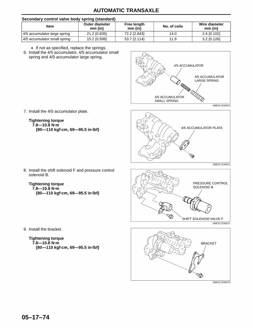
AUTOMATIC TRANSAXLE
05–17–74
Secondary control valve body spring (standard)
• If not as specified, replace the springs.6. Install the 4/5 accumulator, 4/5 accumulator small
spring and 4/5 accumulator large spring.
7. Install the 4/5 accumulator plate.
Tightening torque7.8—10.8 N·m
{80—110 kgf·cm, 69—95.5 in·lbf}
8. Install the shift solenoid F and pressure control solenoid B.
Tightening torque7.8—10.8 N·m
{80—110 kgf·cm, 69—95.5 in·lbf}
9. Install the bracket.
Tightening torque7.8—10.8 N·m
{80—110 kgf·cm, 69—95.5 in·lbf}
End Of Sie
Item Outer diametermm {in}
Free lengthmm {in} No. of coils Wire diameter
mm {in}4/5 accumulator large spring 21.2 {0.835} 72.2 {2.843} 14.0 2.6 {0.102}4/5 accumulator small spring 15.2 {0.598} 53.7 {2.114} 11.9 3.2 {0.126}
4/5 ACCUMULATOR LARGE SPRING
4/5 ACCUMULATOR
4/5 ACCUMULATOR SMALL SPRING
D6E517ZA5073
4/5 ACCUMULATOR PLATE
D6E517ZA5072
SHIFT SOLENOID VALVE F
PRESSURE CONTROL SOLENOID B
D6E517ZA5071
BRACKET
D6E517ZA5070
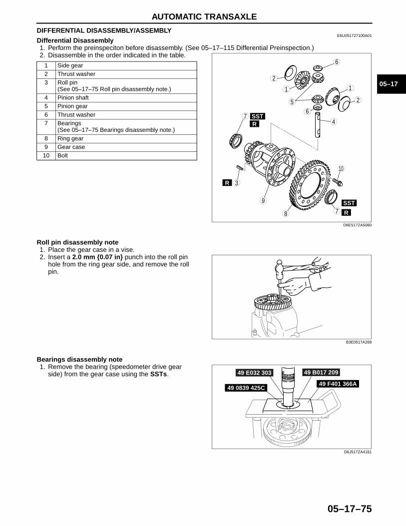
AUTOMATIC TRANSAXLE
05–17–75
05–17
DIFFERENTIAL DISASSEMBLY/ASSEMBLYE6U051727100A01
Differential Disassembly1. Perform the preinspeciton before disassembly. (See 05–17–115 Differential Preinspection.)2. Disassemble in the order indicated in the table.
Roll pin disassembly note1. Place the gear case in a vise.2. Insert a 2.0 mm {0.07 in} punch into the roll pin
hole from the ring gear side, and remove the roll pin.
Bearings disassembly note1. Remove the bearing (speedometer drive gear
side) from the gear case using the SSTs.
1 Side gear2 Thrust washer3 Roll pin
(See 05–17–75 Roll pin disassembly note.)4 Pinion shaft5 Pinion gear6 Thrust washer7 Bearings
(See 05–17–75 Bearings disassembly note.)8 Ring gear9 Gear case10 Bolt
8
7
9
7
5
4
3
SST
SST
R
R
R
6
6
11
2
2
10
D6E517ZA5060
B3E0517A268
49 F401 366A49 0839 425C
49 B017 20949 E032 303
D6J517ZA4161
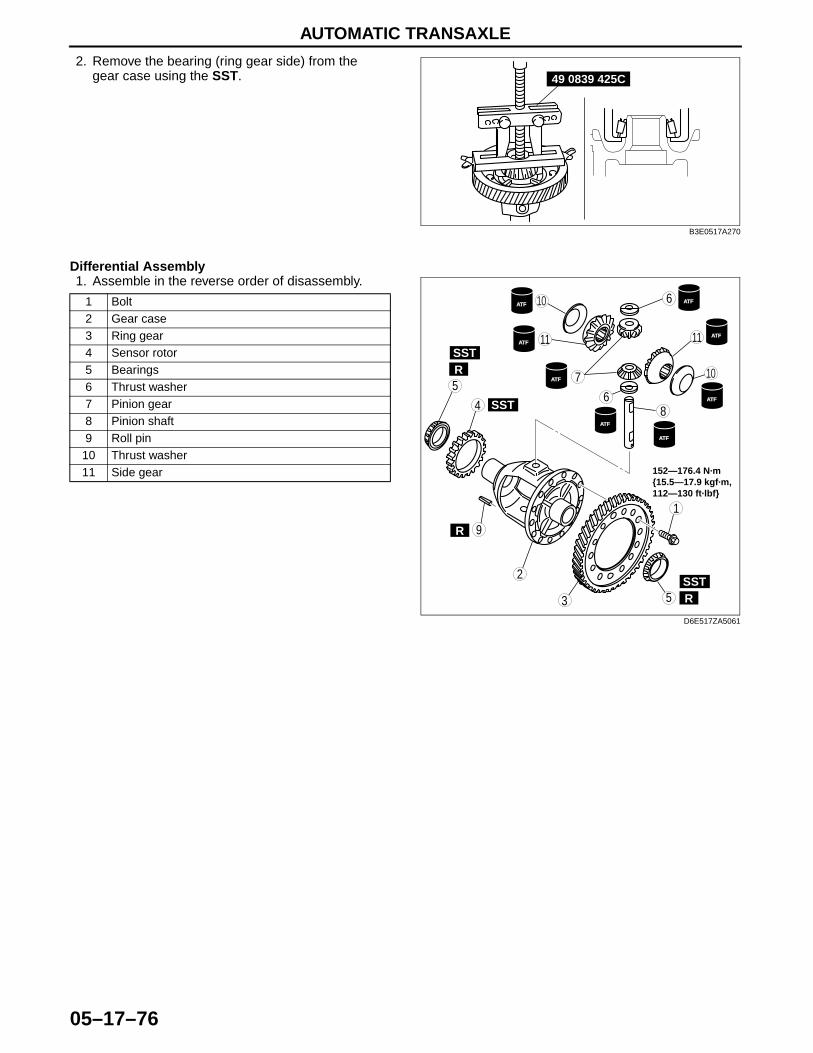
AUTOMATIC TRANSAXLE
05–17–76
2. Remove the bearing (ring gear side) from the gear case using the SST.
Differential Assembly1. Assemble in the reverse order of disassembly.
49 0839 425C
B3E0517A270
1 Bolt2 Gear case3 Ring gear4 Sensor rotor5 Bearings6 Thrust washer7 Pinion gear8 Pinion shaft9 Roll pin
10 Thrust washer11 Side gear
7
9
5
3
SST
SST
R
R
R
6
6
ATF
ATF
ATF
ATF
ATF
ATF
ATF
ATF
1
2
10
8SST4
10
1111
5
152—176.4 N·m {15.5—17.9 kgf·m, 112—130 ft·lbf}
D6E517ZA5061
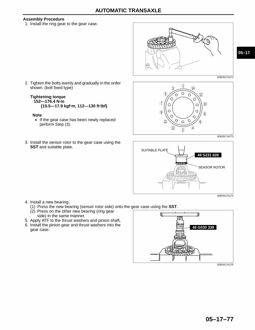
AUTOMATIC TRANSAXLE
05–17–77
05–17
Assembly Procedure1. Install the ring gear to the gear case.
2. Tighten the bolts evenly and gradually in the order shown. (bolt fixed type)
Tightening torque152—176.4 N·m
{15.5—17.9 kgf·m, 112—130 ft·lbf}
Note• If the gear case has been newly replaced
perform Step (3).
3. Install the sensor rotor to the gear case using the SST and suitable plate.
4. Install a new bearing.(1) Press the new bearing (sensor rotor side) onto the gear case using the SST.(2) Press on the other new bearing (ring gear
side) in the same manner.5. Apply ATF to the thrust washers and pinion shaft.6. Install the pinion gear and thrust washers into the
gear case.
B3E0517A272
9 8
7
5
4
3
10
14
13
11
12
6
1
2B3E0517A273
49 S231 626SUITABLE PLATE
SENSOR ROTOR
B3E0517A274
49 G030 338
B3E0517A275
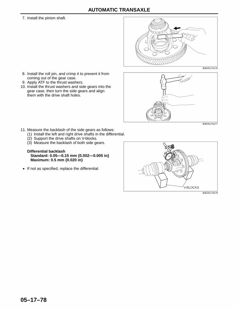
AUTOMATIC TRANSAXLE
05–17–78
7. Install the pinion shaft.
8. Install the roll pin, and crimp it to prevent it from coming out of the gear case.
9. Apply ATF to the thrust washers.10. Install the thrust washers and side gears into the
gear case, then turn the side gears and align them with the drive shaft holes.
11. Measure the backlash of the side gears as follows:(1) Install the left and right drive shafts in the differential.(2) Support the drive shafts on V-blocks.(3) Measure the backlash of both side gears.
Differential backlashStandard: 0.05—0.15 mm {0.002—0.005 in}Maximum: 0.5 mm {0.020 in}
• If not as specified, replace the differential.End Of Sie
B3E0517A276
B3E0517A277
V-BLOCKS
B3E0517A278
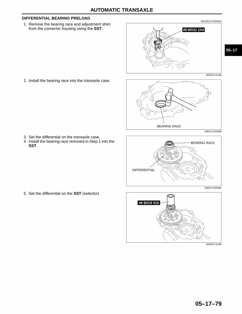
AUTOMATIC TRANSAXLE
05–17–79
05–17
DIFFERENTIAL BEARING PRELOADE6U051727100A02
1. Remove the bearing race and adjustment shim from the converter housing using the SST.
2. Install the bearing race into the transaxle case.
3. Set the differential on the transaxle case.4. Install the bearing race removed in Step 1 into the
SST.
5. Set the differential on the SST (selector).
49 W032 2A0
B3E0517A186
BEARING RACE
D6E517ZA5066
BEARING RACE
DIFFERENTIAL
D6E517ZA5062
49 B019 016
B3E0517A190
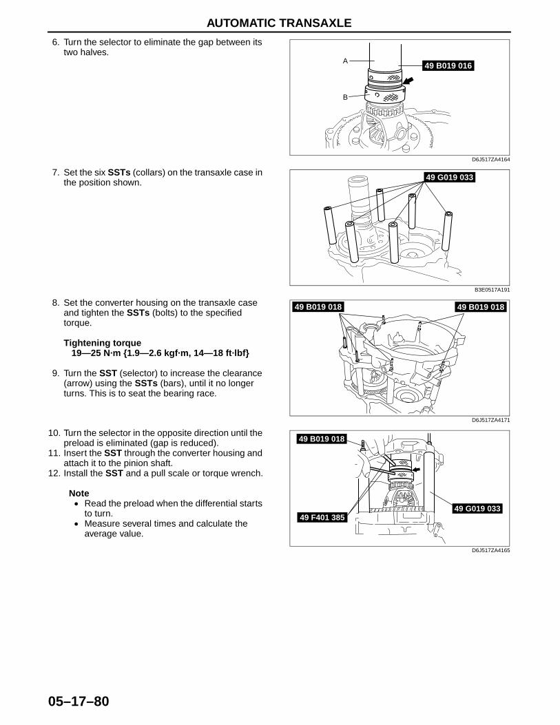
AUTOMATIC TRANSAXLE
05–17–80
6. Turn the selector to eliminate the gap between its two halves.
7. Set the six SSTs (collars) on the transaxle case in the position shown.
8. Set the converter housing on the transaxle case and tighten the SSTs (bolts) to the specified torque.
Tightening torque19—25 N·m {1.9—2.6 kgf·m, 14—18 ft·lbf}
9. Turn the SST (selector) to increase the clearance (arrow) using the SSTs (bars), until it no longer turns. This is to seat the bearing race.
10. Turn the selector in the opposite direction until the preload is eliminated (gap is reduced).
11. Insert the SST through the converter housing and attach it to the pinion shaft.
12. Install the SST and a pull scale or torque wrench.
Note• Read the preload when the differential starts
to turn.• Measure several times and calculate the
average value.
A
B
49 B019 016
D6J517ZA4164
49 G019 033
B3E0517A191
49 B019 01849 B019 018
D6J517ZA4171
49 G019 033
49 B019 018
49 F401 385
D6J517ZA4165

AUTOMATIC TRANSAXLE
05–17–81
05–17
13. Adjust the clearance of the SST (selector) to obtain the specified preload/pull scale reading.
Differential bearing PreloadPreload: 1.4—2.3 N·m {14—24 kgf·cm, 12—
20 in·lbf}Reading on pull scale: 14—23 N {1.4—2.4
kgf, 3.1—5.3 lbf}
Note• Measure the clearance around the entire
circumference, and select a shim based on the maximum clearance.
• The maximum allowable number of adjustment shim is one.
14. Measure the clearance as shown.15. Take the maximum reading and determine the
shim to be used.
Differential preload adjust shims (mm {in})
16. Remove the converter housing and SST (selector).
49 B019 025TORQUE WRENCH
D6E517ZA5065
49 0180 510B
PULL SCALE
D6E517ZA5064
B3E0517A196
0.50 {0.020} 0.55 {0.022} 0.60 {0.024}0.65 {0.026} 0.70 {0.028} 0.75 {0.030}0.80 {0.031} 0.85 {0.033} 0.90 {0.035}0.95 {0.037} 1.00 {0.039} 1.05 {0.041}1.10 {0.043} 1.15 {0.045} 1.20 {0.047}1.25 {0.049} 1.30 {0.051} 1.35 {0.053}1.40 {0.055} 1.45 {0.057} 1.50 {0.059}1.55 {0.061} – –
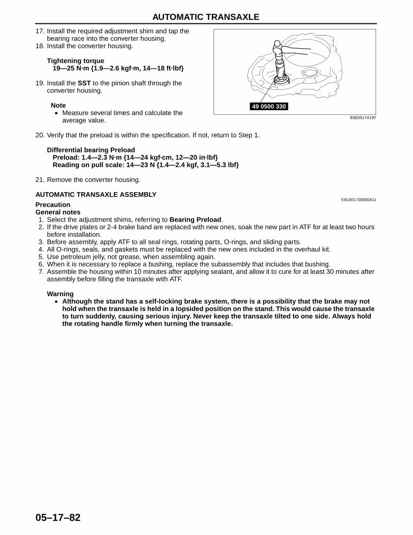
AUTOMATIC TRANSAXLE
05–17–82
17. Install the required adjustment shim and tap the bearing race into the converter housing.
18. Install the converter housing.
Tightening torque19—25 N·m {1.9—2.6 kgf·m, 14—18 ft·lbf}
19. Install the SST to the pinion shaft through the converter housing.
Note• Measure several times and calculate the
average value.
20. Verify that the preload is within the specification. If not, return to Step 1.
Differential bearing PreloadPreload: 1.4—2.3 N·m {14—24 kgf·cm, 12—20 in·lbf}Reading on pull scale: 14—23 N {1.4—2.4 kgf, 3.1—5.3 lbf}
21. Remove the converter housing.End Of SieAUTOMATIC TRANSAXLE ASSEMBLY
E6U051700000A11PrecautionGeneral notes1. Select the adjustment shims, referring to Bearing Preload.2. If the drive plates or 2-4 brake band are replaced with new ones, soak the new part in ATF for at least two hours
before installation.3. Before assembly, apply ATF to all seal rings, rotating parts, O-rings, and sliding parts.4. All O-rings, seals, and gaskets must be replaced with the new ones included in the overhaul kit.5. Use petroleum jelly, not grease, when assembling again.6. When it is necessary to replace a bushing, replace the subassembly that includes that bushing.7. Assemble the housing within 10 minutes after applying sealant, and allow it to cure for at least 30 minutes after
assembly before filling the transaxle with ATF.
Warning• Although the stand has a self-locking brake system, there is a possibility that the brake may not
hold when the transaxle is held in a lopsided position on the stand. This would cause the transaxle to turn suddenly, causing serious injury. Never keep the transaxle tilted to one side. Always hold the rotating handle firmly when turning the transaxle.
49 0500 330
B3E0517A197
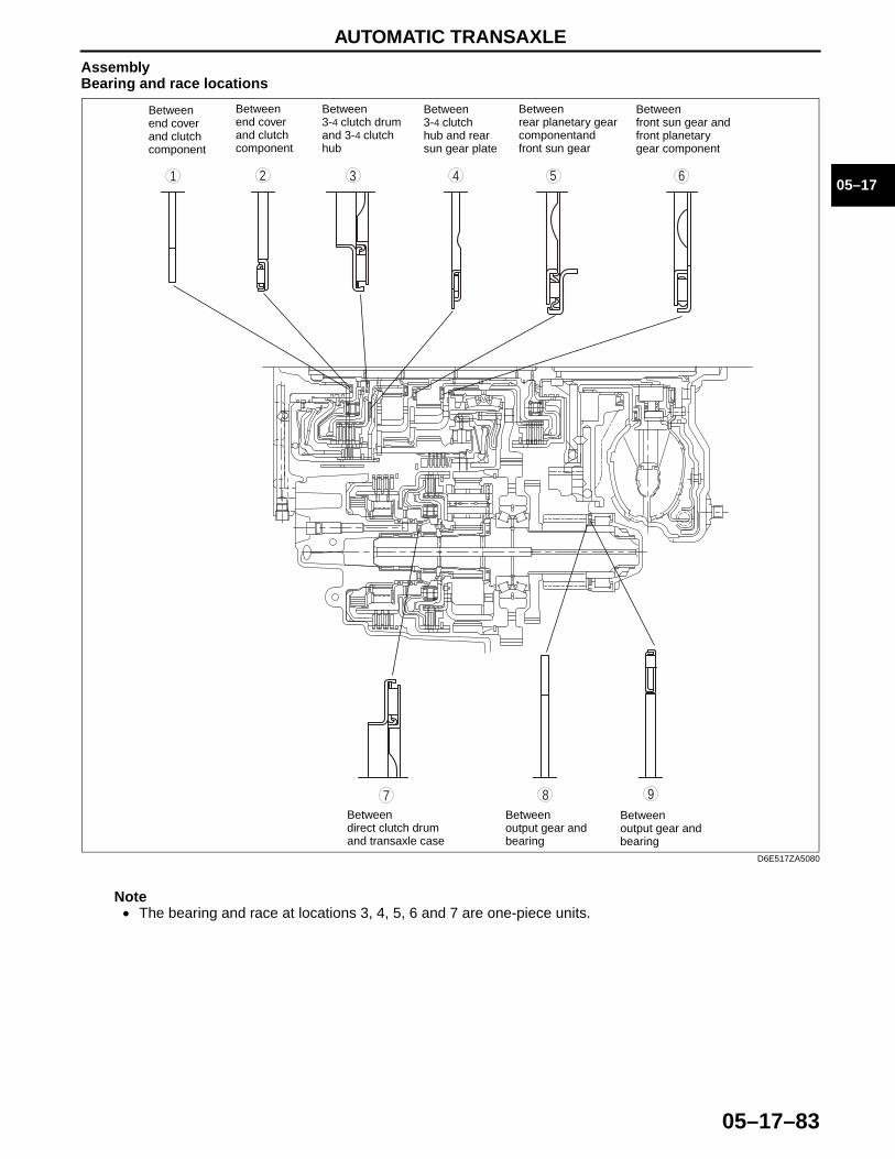
AUTOMATIC TRANSAXLE
05–17–83
05–17
AssemblyBearing and race locations
Note• The bearing and race at locations 3, 4, 5, 6 and 7 are one-piece units.
987
543 61 2
Betweenend coverand clutchcomponent
Betweenend coverand clutchcomponent
Between3-4 clutch drumand 3-4 clutchhub
Between3-4 clutch hub and rearsun gear plate
Betweenrear planetary gearcomponentandfront sun gear
Betweenfront sun gear andfront planetarygear component
Between direct clutch drum and transaxle case
Between output gear and bearing
Between output gear and bearing
D6E517ZA5080
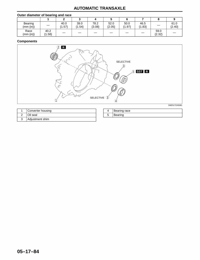
AUTOMATIC TRANSAXLE
05–17–84
Outer diameter of bearing and race
Components
1 2 3 4 5 6 7 8 9Bearing
(mm {in}) — 40.0 {1.57}
39.0 {1.54}
78.2 {3.08}
52.0 {2.05}
50.0 {1.97}
46.5 {1.83} — 61.0
{2.40}Race
(mm {in})40.2
{1.58} — — — — — — 59.0 {2.32} —
5
3
R2
1 43
SST R
SELECTIVE
SELECTIVE
D6E517ZA5081
1 Converter housing2 Oil seal3 Adjustment shim
4 Bearing race5 Bearing

AUTOMATIC TRANSAXLE
05–17–85
05–17
.
SST
SST
R
R
R
A
A
SSTR
987
5
4
3
101311
12
6
1
2 ATF
ATF
ATF
ATF
4
3
PP
19
18
17
15
16
14
20
26
SST
R
ATF
ATF
P
29
28
2725
24
23
2122
30
33
3132
19—25{1.9—2.6, 14—18}
11—14 N·m {113—142 kgf·cm, 98—123 in·lbf} N·m {kgf·m, ft·lbf}
10.8—13.7 N·m {110—140 kgf·cm, 95.5—121 in·lbf}
11—14 N·m {113—142 kgf·cm, 98—123 in·lbf}
SELECTIVE
D6E517ZA5082
1 Transaxle case2 Oil seal3 Oil pipe4 Bearing race5 Primary gear6 Forward clutch hub7 Forward clutch8 Reduction brake piston
9 Springs and retainer component10 Snap ring11 Reduction brake12 Snap ring13 Spacer14 Needle bearing15 Seal rings16 Needle bearing
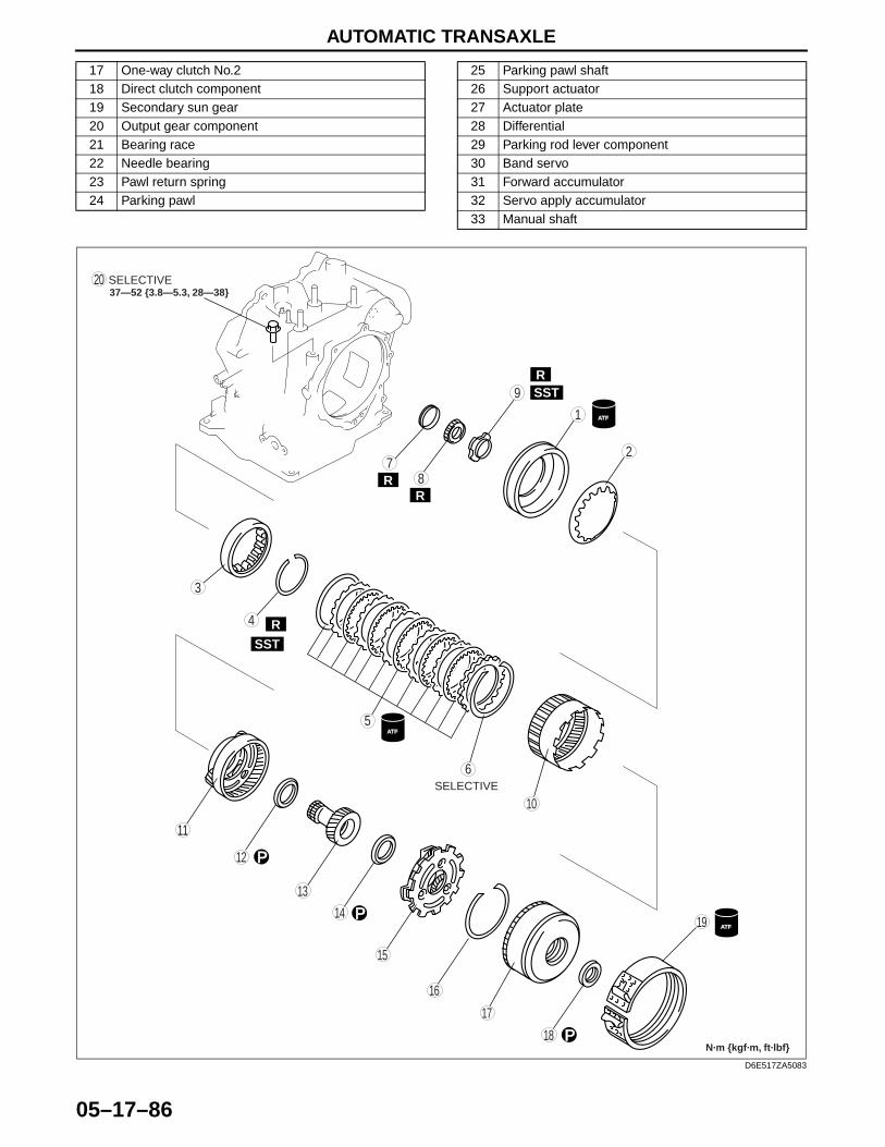
AUTOMATIC TRANSAXLE
05–17–86.
17 One-way clutch No.218 Direct clutch component19 Secondary sun gear20 Output gear component21 Bearing race22 Needle bearing23 Pawl return spring24 Parking pawl
25 Parking pawl shaft26 Support actuator27 Actuator plate28 Differential29 Parking rod lever component30 Band servo31 Forward accumulator32 Servo apply accumulator33 Manual shaft
R
RR
R SST
SST
9
87
5
4
3
10
19
18
17
15
16
14
13
11
12
20
6
1
2
ATF
ATF
P
P
P
R
ATF
SELECTIVE37—52 {3.8—5.3, 28—38}
N·m {kgf·m, ft·lbf}
SELECTIVE
D6E517ZA5083
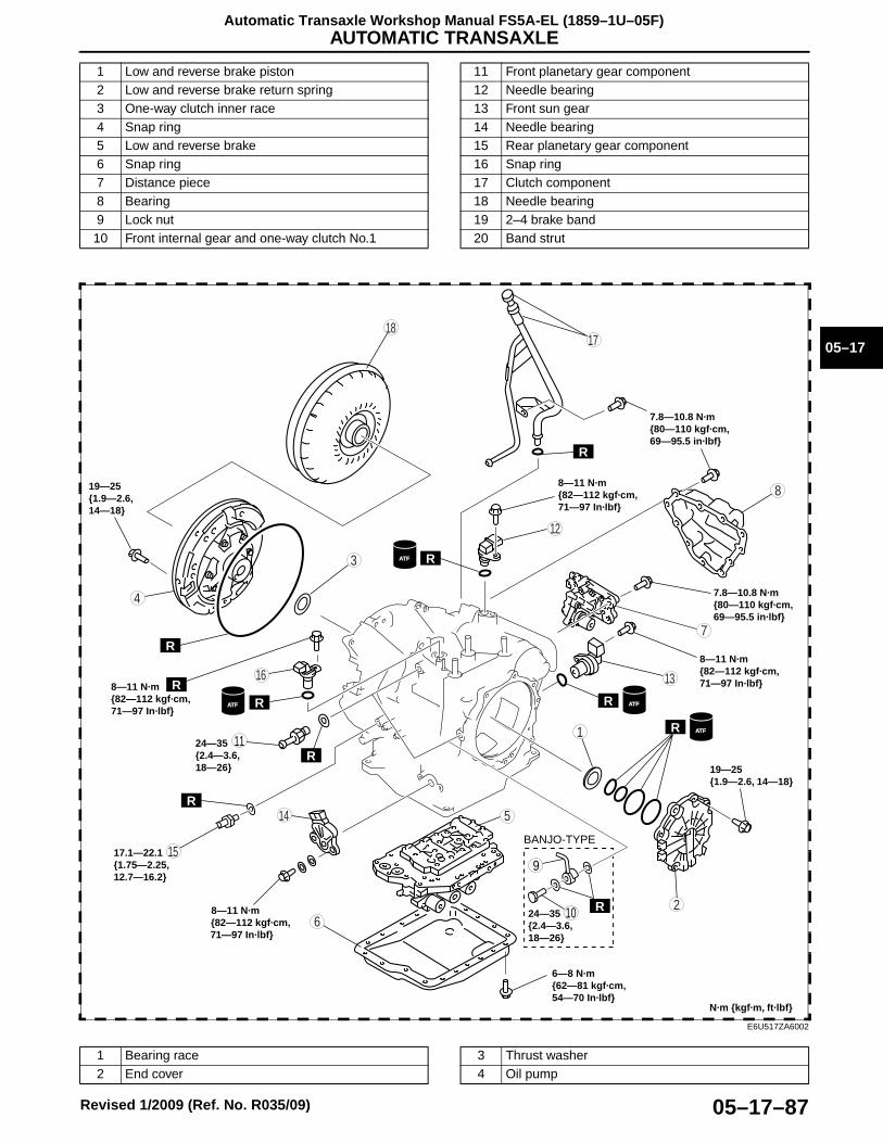
AUTOMATIC TRANSAXLE
05–17–87
05–17
Automatic Transaxle Workshop Manual FS5A-EL (1859–1U–05F)
Revised 1/2009 (Ref. No. R035/09)
.
1 Low and reverse brake piston2 Low and reverse brake return spring 3 One-way clutch inner race 4 Snap ring 5 Low and reverse brake 6 Snap ring7 Distance piece8 Bearing9 Lock nut10 Front internal gear and one-way clutch No.1
11 Front planetary gear component12 Needle bearing13 Front sun gear14 Needle bearing15 Rear planetary gear component16 Snap ring17 Clutch component18 Needle bearing19 2–4 brake band20 Band strut
R
R
R
R
R
R
8
7
5
4
3
6
1
2
R
ATF ATF
ATFTF
R
ATF
8—11 N·m {82—112 kgf·cm, 71—97 In·lbf}
24—35 {2.4—3.6, 18—26}
17.1—22.1 {1.75—2.25, 12.7—16.2}
8—11 N·m {82—112 kgf·cm, 71—97 In·lbf}
6—8 N·m {62—81 kgf·cm, 54—70 In·lbf}
N·m {kgf·m, ft·lbf}
19—25{1.9—2.6, 14—18}
19—25 {1.9—2.6, 14—18}
8—11 N·m {82—112 kgf·cm, 71—97 In·lbf}
8—11 N·m {82—112 kgf·cm, 71—97 In·lbf}
7.8—10.8 N·m {80—110 kgf·cm, 69—95.5 in·lbf}
7.8—10.8 N·m {80—110 kgf·cm, 69—95.5 in·lbf}
10
9
RR
BANJO-TYPE
24—35 {2.4—3.6, 18—26}
1817
15
16
14
13
11
12
R
E6U517ZA6002
1 Bearing race2 End cover
3 Thrust washer4 Oil pump
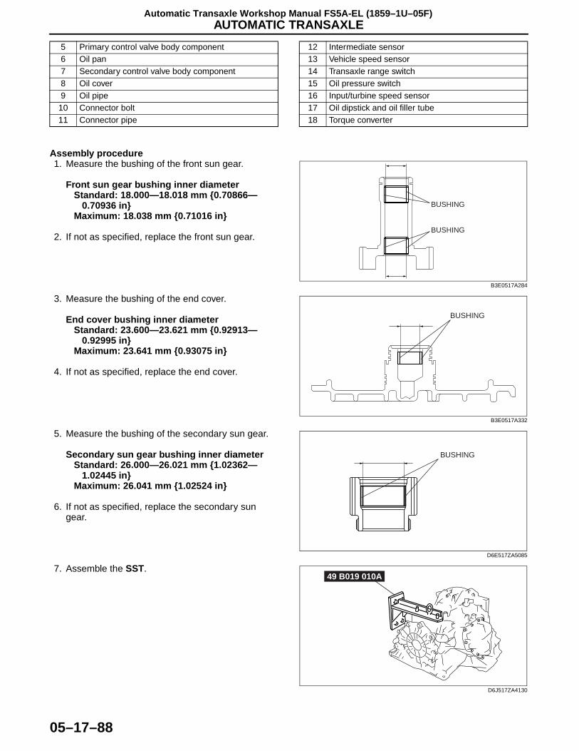
AUTOMATIC TRANSAXLE
05–17–88
Automatic Transaxle Workshop Manual FS5A-EL (1859–1U–05F)
Assembly procedure1. Measure the bushing of the front sun gear.
Front sun gear bushing inner diameterStandard: 18.000—18.018 mm {0.70866—
0.70936 in}Maximum: 18.038 mm {0.71016 in}
2. If not as specified, replace the front sun gear.
3. Measure the bushing of the end cover.
End cover bushing inner diameterStandard: 23.600—23.621 mm {0.92913—
0.92995 in}Maximum: 23.641 mm {0.93075 in}
4. If not as specified, replace the end cover.
5. Measure the bushing of the secondary sun gear.
Secondary sun gear bushing inner diameterStandard: 26.000—26.021 mm {1.02362—
1.02445 in}Maximum: 26.041 mm {1.02524 in}
6. If not as specified, replace the secondary sun gear.
7. Assemble the SST.
5 Primary control valve body component6 Oil pan7 Secondary control valve body component8 Oil cover9 Oil pipe
10 Connector bolt11 Connector pipe
12 Intermediate sensor13 Vehicle speed sensor14 Transaxle range switch15 Oil pressure switch16 Input/turbine speed sensor17 Oil dipstick and oil filler tube18 Torque converter
BUSHING
BUSHING
B3E0517A284
BUSHING
B3E0517A332
BUSHING
D6E517ZA5085
49 B019 010A
D6J517ZA4130
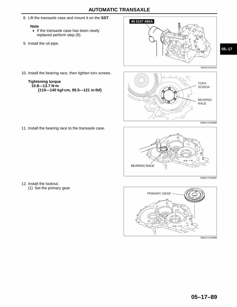
AUTOMATIC TRANSAXLE
05–17–89
05–17
8. Lift the transaxle case and mount it on the SST.
Note• If the transaxle case has been newly
replaced perform step (9).
9. Install the oil pipe.
10. Install the bearing race, then tighten torx screws.
Tightening torque10.8—13.7 N·m
{110—140 kgf·cm, 95.5—121 in·lbf}
11. Install the bearing race to the transaxle case.
12. Install the locknut.(1) Set the primary gear.
49 0107 680A
D6J517ZA4131
TORX SCREW
BEARING RACE
D6E517ZA5086
BEARING RACE
D6E517ZA5087
PRIMARY GEAR
D6E517ZA5088
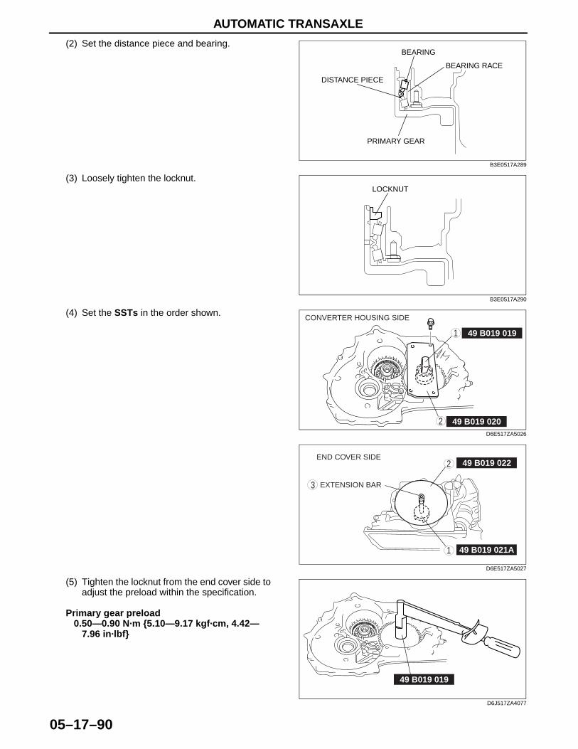
AUTOMATIC TRANSAXLE
05–17–90
(2) Set the distance piece and bearing.
(3) Loosely tighten the locknut.
(4) Set the SSTs in the order shown.
(5) Tighten the locknut from the end cover side to adjust the preload within the specification.
Primary gear preload0.50—0.90 N·m {5.10—9.17 kgf·cm, 4.42—
7.96 in·lbf}
BEARING
DISTANCE PIECE
PRIMARY GEAR
BEARING RACE
B3E0517A289
LOCKNUT
B3E0517A290
49 B019 019
49 B019 020
1
2
CONVERTER HOUSING SIDE
D6E517ZA5026
49 B019 0222
3
1 49 B019 021A
EXTENSION BAR
END COVER SIDE
D6E517ZA5027
49 B019 019
D6J517ZA4077
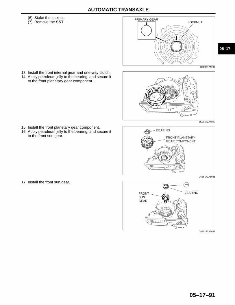
AUTOMATIC TRANSAXLE
05–17–91
05–17
(6) Stake the locknut.(7) Remove the SST
13. Install the front internal gear and one-way clutch. 14. Apply petroleum jelly to the bearing, and secure it
to the front planetary gear component.
15. Install the front planetary gear component.16. Apply petroleum jelly to the bearing, and secure it
to the front sun gear.
17. Install the front sun gear.
LOCKNUTPRIMARY GEAR
B3E0517A292
D6J517ZA4028
FRONT PLANETARYGEAR COMPONENT
BEARING
D6E517ZA5025
BEARINGFRONTSUNGEAR
D6E517ZA5089

AUTOMATIC TRANSAXLE
05–17–92
18. Install the rear planetary gear.
Note• Rotate the engine stand so that the oil pan
faces downward. Pull the front internal gear and one-way clutch component a little until the groove for the snap ring appears, then install the snap ring.
19. Install the snap ring.20. Rotate the engine stand so that the end cover
faces upward, and verify that the snap ring is installed accurately.
21. Install the band servo component. (1) Install the servo return spring and servo piston.(2) Apply ATF to the O-ring, and install it to the transaxle case.(3) Install the servo retainer.
Tightening torque11—14 N·m {113—142 kgf·cm, 98—123
in·lbf}
22. Apply petroleum jelly to the bearing, and secure it to the clutch component.
D6J517ZA4025
GROOVEFOR THESNAP RING
FRONT INTERNAL GEARAND ONE-WAY CLUTCH
B3E0517A294
D6J517ZA4075
BAND SERVO INSTALLATION BOLTS
D6E517ZA5014

AUTOMATIC TRANSAXLE
05–17–93
05–17
23. Install the clutch component.
24. Install the 2-4 brake band.
25. Select the band strut.(1) Find an appropriate bolt (under head length: 60—70 mm {2.36—2.75 in}), and tighten the 2-4 brake band
with the bolt.
Tightening torque4.9 N·m {50 kgf·cm, 43 in·lbf}
(2) Measure the dimension A shown in the figure.(3) Remove the bolt.
(4) Measure the dimension B shown in the figure.(5) Calculate according to the formula below.
B – A = C (The middle of the under head length)
C – 4 = D (The lower limit of under head length)
C – 4.7 = E (The upper limit of under head length)
(6) Select a band strut whose length should be between D and E.
D6J517ZA4023
D6J517ZA4066
A
B3E0517A297
B
B3E0517A298
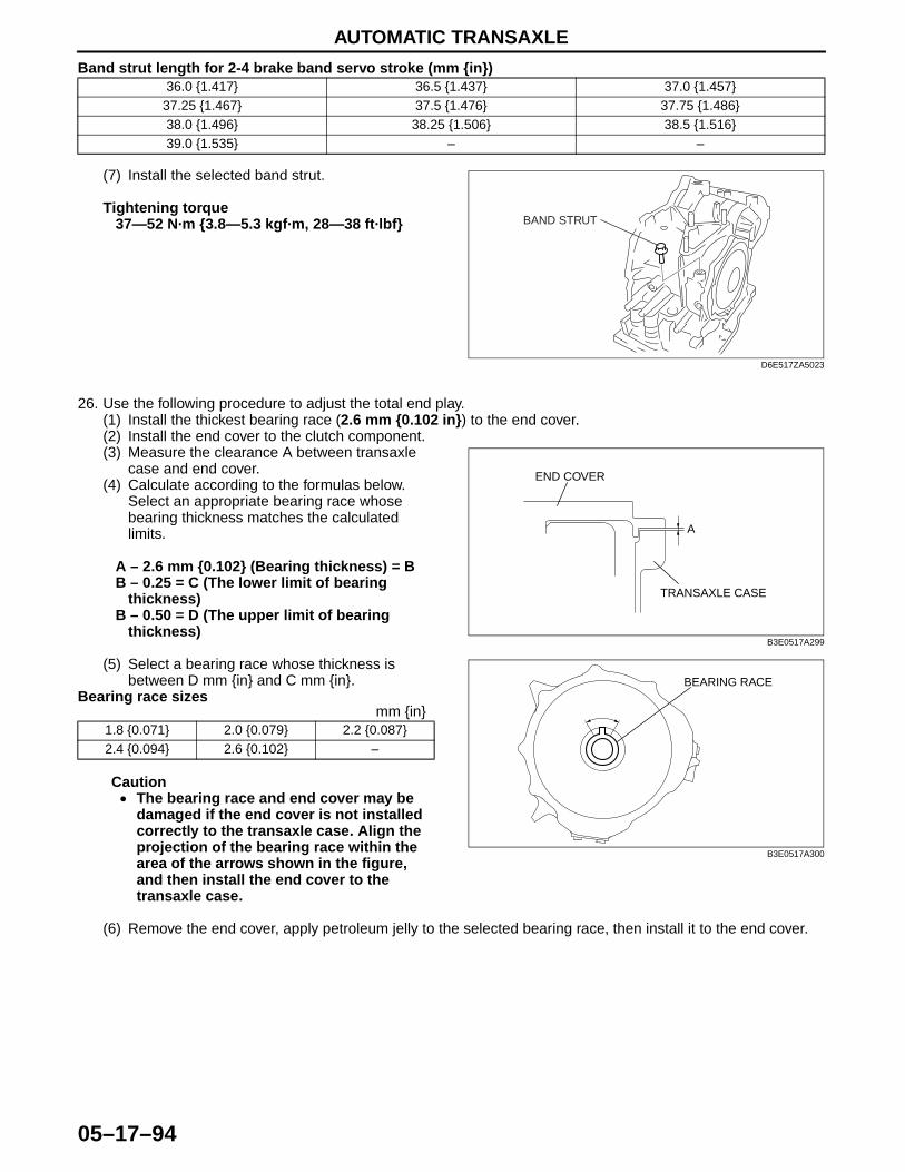
AUTOMATIC TRANSAXLE
05–17–94
Band strut length for 2-4 brake band servo stroke (mm {in})
(7) Install the selected band strut.
Tightening torque37—52 N·m {3.8—5.3 kgf·m, 28—38 ft·lbf}
26. Use the following procedure to adjust the total end play.(1) Install the thickest bearing race (2.6 mm {0.102 in}) to the end cover.(2) Install the end cover to the clutch component.(3) Measure the clearance A between transaxle
case and end cover.(4) Calculate according to the formulas below.
Select an appropriate bearing race whose bearing thickness matches the calculated limits.
A – 2.6 mm {0.102} (Bearing thickness) = BB – 0.25 = C (The lower limit of bearing
thickness)B – 0.50 = D (The upper limit of bearing
thickness)
(5) Select a bearing race whose thickness is between D mm {in} and C mm {in}.
Bearing race sizesmm {in}
Caution• The bearing race and end cover may be
damaged if the end cover is not installed correctly to the transaxle case. Align the projection of the bearing race within the area of the arrows shown in the figure, and then install the end cover to the transaxle case.
(6) Remove the end cover, apply petroleum jelly to the selected bearing race, then install it to the end cover.
36.0 {1.417} 36.5 {1.437} 37.0 {1.457}37.25 {1.467} 37.5 {1.476} 37.75 {1.486}38.0 {1.496} 38.25 {1.506} 38.5 {1.516}39.0 {1.535} – –
BAND STRUT
D6E517ZA5023
1.8 {0.071} 2.0 {0.079} 2.2 {0.087}2.4 {0.094} 2.6 {0.102} –
TRANSAXLE CASE
END COVER
A
B3E0517A299
BEARING RACE
B3E0517A300
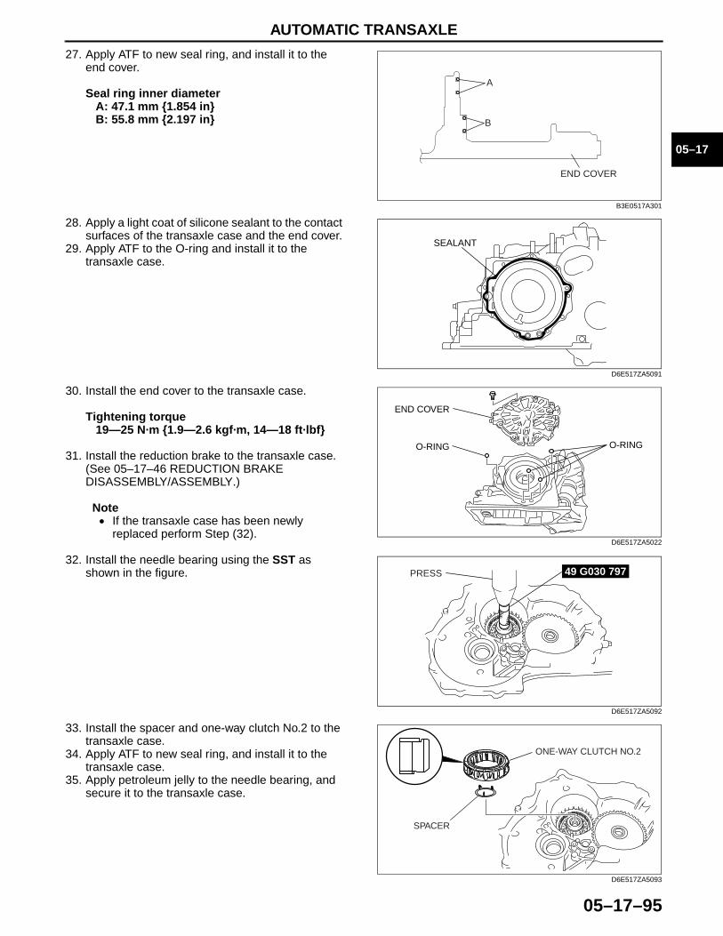
AUTOMATIC TRANSAXLE
05–17–95
05–17
27. Apply ATF to new seal ring, and install it to the end cover.
Seal ring inner diameterA: 47.1 mm {1.854 in}B: 55.8 mm {2.197 in}
28. Apply a light coat of silicone sealant to the contact surfaces of the transaxle case and the end cover.
29. Apply ATF to the O-ring and install it to the transaxle case.
30. Install the end cover to the transaxle case.
Tightening torque19—25 N·m {1.9—2.6 kgf·m, 14—18 ft·lbf}
31. Install the reduction brake to the transaxle case. (See 05–17–46 REDUCTION BRAKE DISASSEMBLY/ASSEMBLY.)
Note• If the transaxle case has been newly
replaced perform Step (32).
32. Install the needle bearing using the SST as shown in the figure.
33. Install the spacer and one-way clutch No.2 to the transaxle case.
34. Apply ATF to new seal ring, and install it to the transaxle case.
35. Apply petroleum jelly to the needle bearing, and secure it to the transaxle case.
A
B
END COVER
B3E0517A301
SEALANT
D6E517ZA5091
O-RINGO-RING
END COVER
D6E517ZA5022
PRESS 49 G030 797
D6E517ZA5092
SPACER
ONE-WAY CLUTCH NO.2
D6E517ZA5093
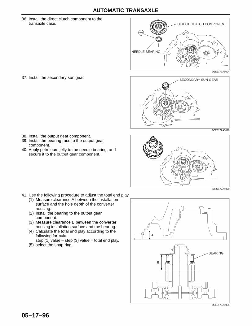
AUTOMATIC TRANSAXLE
05–17–96
36. Install the direct clutch component to the transaxle case.
37. Install the secondary sun gear.
38. Install the output gear component.39. Install the bearing race to the output gear
component.40. Apply petroleum jelly to the needle bearing, and
secure it to the output gear component.
41. Use the following procedure to adjust the total end play.(1) Measure clearance A between the installation
surface and the hole depth of the converter housing.
(2) Install the bearing to the output gear component.
(3) Measure clearance B between the converter housing installation surface and the bearing.
(4) Calculate the total end play according to the following formula:step (1) value – step (3) value = total end play.
(5) select the snap ring.
NEEDLE BEARING
DIRECT CLUTCH COMPONENT
D6E517ZA5094
SECONDARY SUN GEAR
D6E517ZA5019
D6J517ZA4039
BEARING
B
A
D6E517ZA5095

AUTOMATIC TRANSAXLE
05–17–97
05–17
Adjust shim size for output gear component total end play
(6) Install the selected adjustment shim to the converter housing.42. Install the bearing using the SST as shown in the
figure.
Press-in force8.8 kN {897 kgf, 1978 lbf}
43. Install the pawl return spring to the transaxle case.
44. Install the packing pawl and parking pawl shaft to the transaxle case.
total end play {in} Adjust shims sizes mm {in}1.431—1.481 {0.057—0.058} 1.20 {0.047}1.381—1.431 {0.055—0.056} 1.15 {0.045}1.331—1.381 {0.053—0.054} 1.10 {0.043}1.281—1.331 {0.051—0.052} 1.05 {0.041}1.231—1.281 {0.049—0.050} 1.00 {0.039}1.181—1.231 {0.047—0.048} 0.95 {0.037}1.131—1.181 {0.045—0.046} 0.90 {0.035}1.081—1.131 {0.043—0.044} 0.85 {0.033}1.031—1.081 {0.041—0.042} 0.80 {0.031}0.981—1.031 {0.039—0.040} 0.75 {0.029}0.931—0.981 {0.037—0.038} 0.70 {0.028}0.881—0.931 {0.035—0.036} 0.65 {0.026}0.831—0.881 {0.033—0.034} 0.60 {0.024}0.781—0.831 {0.031—0.032} 0.55 {0.022}0.731—0.781 {0.029—0.030} 0.50 {0.020}
PRESS 49 G030 797
49 G030 796
D6E517ZA5096
PAWL RETURN SPRING
D6E517ZA5018
PARKING PAWL
PARKING PAWL SHAFT
D6E517ZA5017
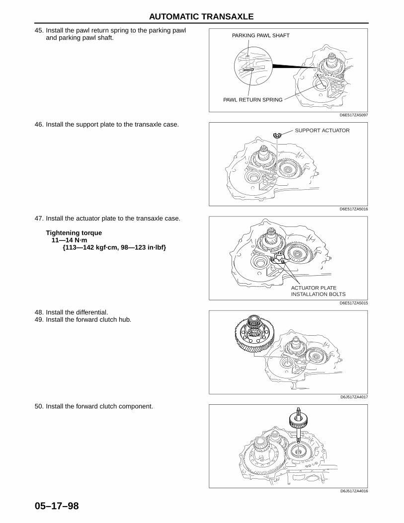
AUTOMATIC TRANSAXLE
05–17–98
45. Install the pawl return spring to the parking pawl and parking pawl shaft.
46. Install the support plate to the transaxle case.
47. Install the actuator plate to the transaxle case.
Tightening torque11—14 N·m
{113—142 kgf·cm, 98—123 in·lbf}
48. Install the differential. 49. Install the forward clutch hub.
50. Install the forward clutch component.
PARKING PAWL SHAFT
PAWL RETURN SPRING
D6E517ZA5097
SUPPORT ACTUATOR
D6E517ZA5016
ACTUATOR PLATEINSTALLATION BOLTS
D6E517ZA5015
D6J517ZA4017
D6J517ZA4016
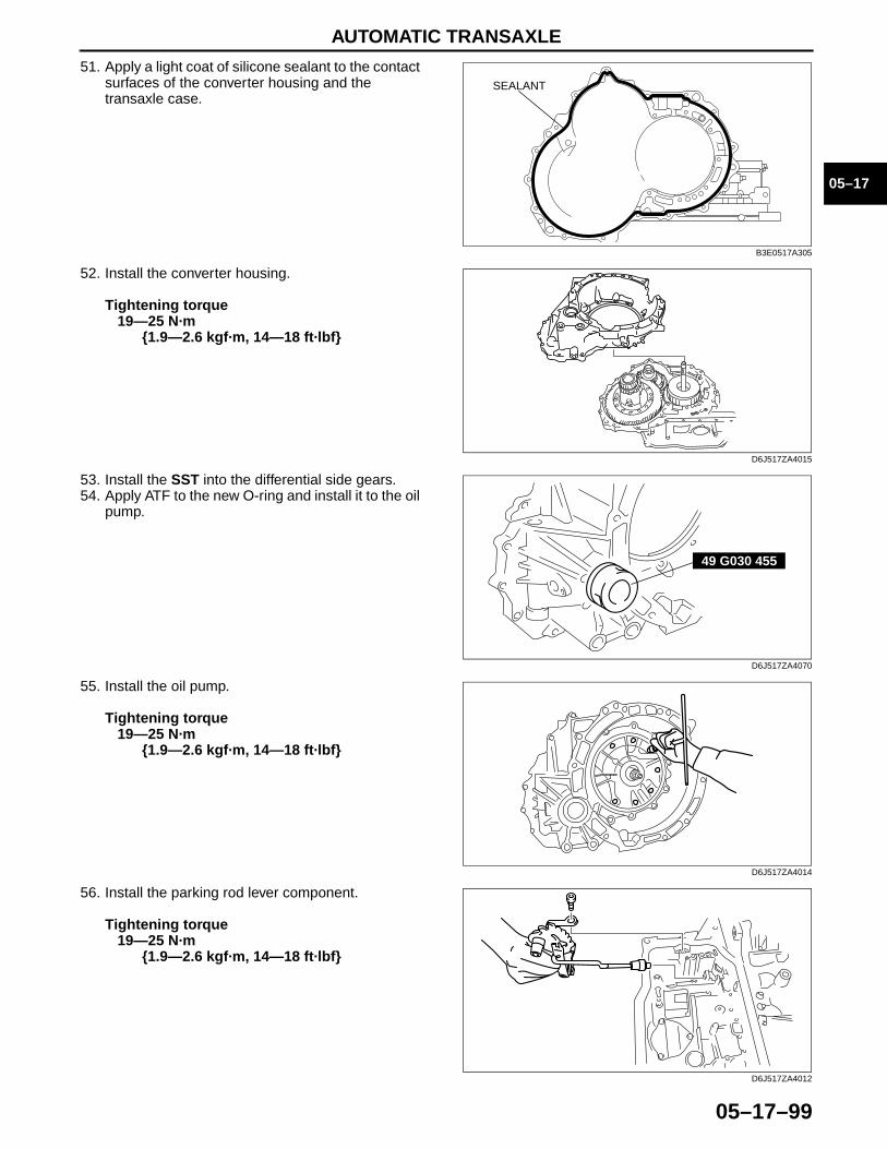
AUTOMATIC TRANSAXLE
05–17–99
05–17
51. Apply a light coat of silicone sealant to the contact surfaces of the converter housing and the transaxle case.
52. Install the converter housing.
Tightening torque19—25 N·m
{1.9—2.6 kgf·m, 14—18 ft·lbf}
53. Install the SST into the differential side gears.54. Apply ATF to the new O-ring and install it to the oil
pump.
55. Install the oil pump.
Tightening torque19—25 N·m
{1.9—2.6 kgf·m, 14—18 ft·lbf}
56. Install the parking rod lever component.
Tightening torque19—25 N·m
{1.9—2.6 kgf·m, 14—18 ft·lbf}
SEALANT
B3E0517A305
D6J517ZA4015
49 G030 455
D6J517ZA4070
D6J517ZA4014
D6J517ZA4012
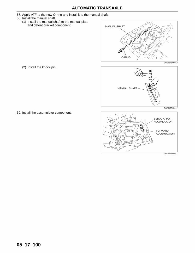
AUTOMATIC TRANSAXLE
05–17–100
57. Apply ATF to the new O-ring and install it to the manual shaft. 58. Install the manual shaft.
(1) Install the manual shaft to the manual plate and detent bracket component.
(2) Install the knock pin.
59. Install the accumulator component.
MANUAL SHAFT
O-RING
D6E517ZA5013
MANUAL SHAFT
D6E517ZA5012
FORWARDACCUMULATOR
SERVO APPLYACCUMULATOR
D6E517ZA5011
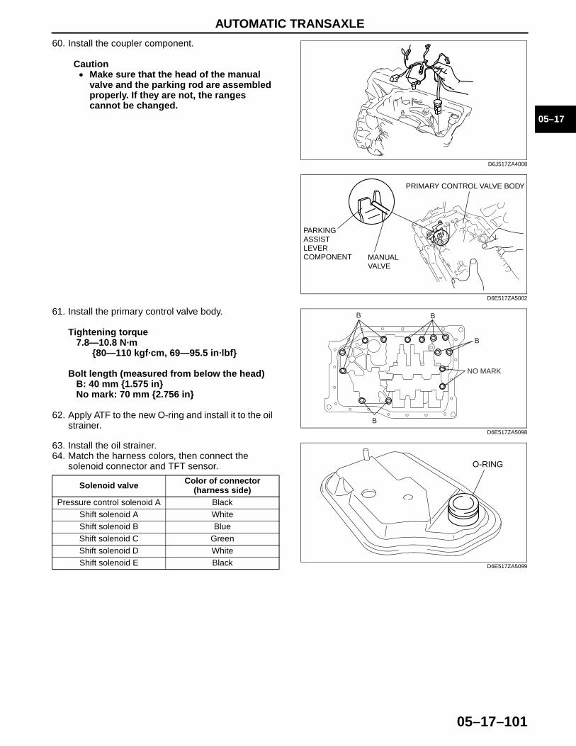
AUTOMATIC TRANSAXLE
05–17–101
05–17
60. Install the coupler component.
Caution• Make sure that the head of the manual
valve and the parking rod are assembled properly. If they are not, the ranges cannot be changed.
61. Install the primary control valve body.
Tightening torque7.8—10.8 N·m
{80—110 kgf·cm, 69—95.5 in·lbf}
Bolt length (measured from below the head)B: 40 mm {1.575 in}No mark: 70 mm {2.756 in}
62. Apply ATF to the new O-ring and install it to the oil strainer.
63. Install the oil strainer.64. Match the harness colors, then connect the
solenoid connector and TFT sensor.
Solenoid valve Color of connector (harness side)
Pressure control solenoid A BlackShift solenoid A WhiteShift solenoid B BlueShift solenoid C GreenShift solenoid D WhiteShift solenoid E Black
D6J517ZA4008
PARKINGASSISTLEVERCOMPONENT MANUAL
VALVE
PRIMARY CONTROL VALVE BODY
D6E517ZA5002
B
BB
B
NO MARK
D6E517ZA5098
O-RING
D6E517ZA5099
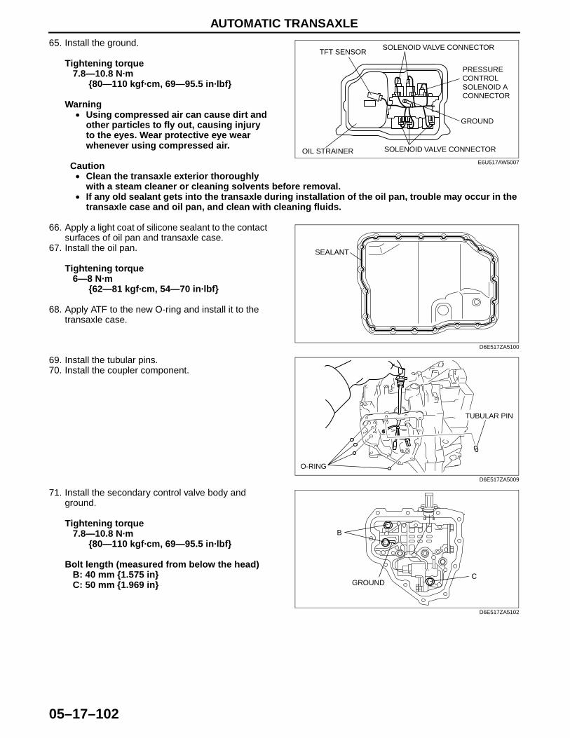
AUTOMATIC TRANSAXLE
05–17–102
65. Install the ground.
Tightening torque7.8—10.8 N·m
{80—110 kgf·cm, 69—95.5 in·lbf}
Warning• Using compressed air can cause dirt and
other particles to fly out, causing injury to the eyes. Wear protective eye wear whenever using compressed air.
Caution• Clean the transaxle exterior thoroughly
with a steam cleaner or cleaning solvents before removal.• If any old sealant gets into the transaxle during installation of the oil pan, trouble may occur in the
transaxle case and oil pan, and clean with cleaning fluids.
66. Apply a light coat of silicone sealant to the contact surfaces of oil pan and transaxle case.
67. Install the oil pan.
Tightening torque6—8 N·m
{62—81 kgf·cm, 54—70 in·lbf}
68. Apply ATF to the new O-ring and install it to the transaxle case.
69. Install the tubular pins.70. Install the coupler component.
71. Install the secondary control valve body and ground.
Tightening torque7.8—10.8 N·m
{80—110 kgf·cm, 69—95.5 in·lbf}
Bolt length (measured from below the head)B: 40 mm {1.575 in}C: 50 mm {1.969 in}
TFT SENSORSOLENOID VALVE CONNECTOR
PRESSURE CONTROL SOLENOID A CONNECTOR
GROUND
SOLENOID VALVE CONNECTOROIL STRAINERE6U517AW5007
SEALANT
D6E517ZA5100
TUBULAR PIN
O-RING
D6E517ZA5009
B
CGROUND
D6E517ZA5102

AUTOMATIC TRANSAXLE
05–17–103
05–17
Automatic Transaxle Workshop Manual FS5A-EL (1859–1U–05F)
Revised 1/2009 (Ref. No. R035/09)
72. Match the harness colors, then connect the solenoid connector.
Warning• Using compressed air can cause dirt and other particles to fly out, causing injury to the eyes.
Wear protective eye wear whenever using compressed air.
Caution• Clean the transaxle exterior thoroughly with a steam cleaner or cleaning solvents before removal.• If any old sealant gets into the transaxle during installation of the oil cover, trouble may occur in
the transaxle case and oil pan, and clean with cleaning fluids.
73. Apply a light coat of silicone sealant to the contact surfaces of oil cover and transaxle case.
74. Install the oil cover.
Tightening torque7.8—10.8 N·m
{80—110 kgf·cm, 69—95.5 in·lbf}
75. Install the oil pipe and connector bolt.
Tightening torque24—35 N·m
{2.4—3.6 kgf·cm, 18—26 in·lbf}
76. Install the connector pipe.
Tightening torque24—35 N·m
{2.4—3.6 kgf·cm, 18—26 in·lbf}
77. Apply ATF to the new O-ring and install it to the intermediate sensor.78. Install the intermediate sensor.
Tightening torque8—11 N·m
{82—112 kgf·cm, 71—97 in·lbf}
79. Apply ATF to the new O-ring and install it to the vehicle speed sensor.80. Install the vehicle speed sensor.
Tightening torque8—11 N·m
{82—112 kgf·cm, 71—97 in·lbf}
81. Apply ATF to the new O-ring and install it to the input/turbine speed sensor.82. Install the oil pressure switch.
Tightening torque17.1—22.1 N·m
{1.75—2.25 kgf·m, 12.7—16.2 ft·lbf}
83. Install the input/turbine speed sensor using a new bolt.
Caution• Always use a new bolt. If the removed bolt is reused, it may cause oil leakage.• A sealant coating is applied to the input/turbine speed sensor installation bolt to prevent oil
leakage from the installation bolt hole which passes through the component.
Tightening torque8—11 N·m
{82—112 kgf·cm, 71—97 in·lbf}
Solenoid valve Color of connector (harness side)
Pressure control solenoid B WhiteShift solenoid F Black
SEALANT
D6E517ZA5101
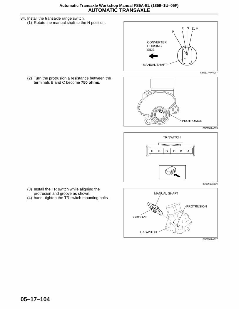
AUTOMATIC TRANSAXLE
05–17–104
Automatic Transaxle Workshop Manual FS5A-EL (1859–1U–05F)
84. Install the transaxle range switch.(1) Rotate the manual shaft to the N position.
(2) Turn the protrusion a resistance between the terminals B and C become 750 ohms.
(3) Install the TR switch while aligning the protrusion and groove as shown.
(4) hand- tighten the TR switch mounting bolts.
PR N D, M
CONVERTERHOUSINGSIDE
MANUAL SHAFT
D6E517AW5007
PROTRUSION
B3E0517A315
F E D C B A
TR SWITCH
B3E0517A316
TR SWITCH
GROOVE
MANUAL SHAFT
PROTRUSION
B3E0517A317

AUTOMATIC TRANSAXLE
05–17–105
05–17
(5) Inspect the resistance between the terminals B and C.• If not as specified, readjust the TR switch.
Resistance750 ohms
(6) Tighten the TR switch mounting bolts
Tightening torque8—11 N·m
{82—112 kgf·cm, 71—97 in·lbf}
Caution• Do not use an impact wrench. Hold the manual shaft lever when removing the manual shaft nut, or
the transaxle may be damaged.
(7) Install the manual shaft lever and the washer.
(8) Set the adjustable wrench as shown to hold the manual shaft lever, and tighten the manual shaft nut.
Tightening torque32—46 N·m
{3.2—4.7 kgf·m, 24—33 ft·lbf}
85. Remove the transaxle from the SST.86. Apply ATF to the new O-ring and install it to the oil
filler tube.87. Install the oil dipstick and oil filler tube to the
transaxle.
Tightening torque7.8—10.8 N·m
{80—110 kgf·cm, 69—95.5 in·lbf}
88. Drain any ATF remaining in the torque converter.89. Pour in solvent (approx. 0.5 L {0.53 US qt, 0.44 lmp qt}),90. Shake the torque converter to clean the inside.91. Pour out the solvent.92. Pour the ATF.
F E D C B A
TR SWITCH
B3E0517A316
MANUAL SHAFTLEVER
WASHER
MANUAL SHAFT NUT
B3E0517A318
MANUALSHAFTLEVER
ADJUSTABLEWRENCH
TORQUEWRENCH
B3E0517A319

AUTOMATIC TRANSAXLE
05–17–106
93. Install the torque converter by aligning its gap to the oil pump inner rotor gap as shown in the figure.
94. To ensure that the torque converter is installed accurately, measure distance A between the end of the torque converter and the end of the converter housing.
Between the end of the torque converter and the end of the converter housing
Distance A: 21.4 mm {0.84 in}
End Of Sie
AUTOMATIC TRANSAXLE INSPECTIONE6U051700000A12
Torque Converter Inspection1. Inspect the outer surface of the torque converter for damage or cracks, and replace it if necessary.2. Inspect for rust on the pilot hub of the torque converter or on the boss. If there is any, remove the rust
completely.
Oil Pump Preinspection1. Measure the bushing of the oil pump.
Oil Pump bushing inner diameter torque converter side
Standard: 40.015—40.040 mm {1.57539—1.57637 in}
Maximum: 40.060 mm {1.57716 in}
Oil Pump bushing inner diameter forward clutch side
Standard: 19.000—19.021 mm {0.74803—0.74885 in}
Maximum: 19.041 mm {0.74964 in}
2. If not as specified, replace the oil pump housing and oil pump cover. (See 05–17–18 OIL PUMP DISASSEMBLY/ASSEMBLY.)
INNER ROTOR SIDE(OIL PUMP)
TORQUECONVERTER SIDE
D6E517ZA5103
A
B3E0517A321
TORQUE CONVERTER SIDE
FORWARD CLUTCH SIDE
BUSHING
BUSHING
B3E0517A322
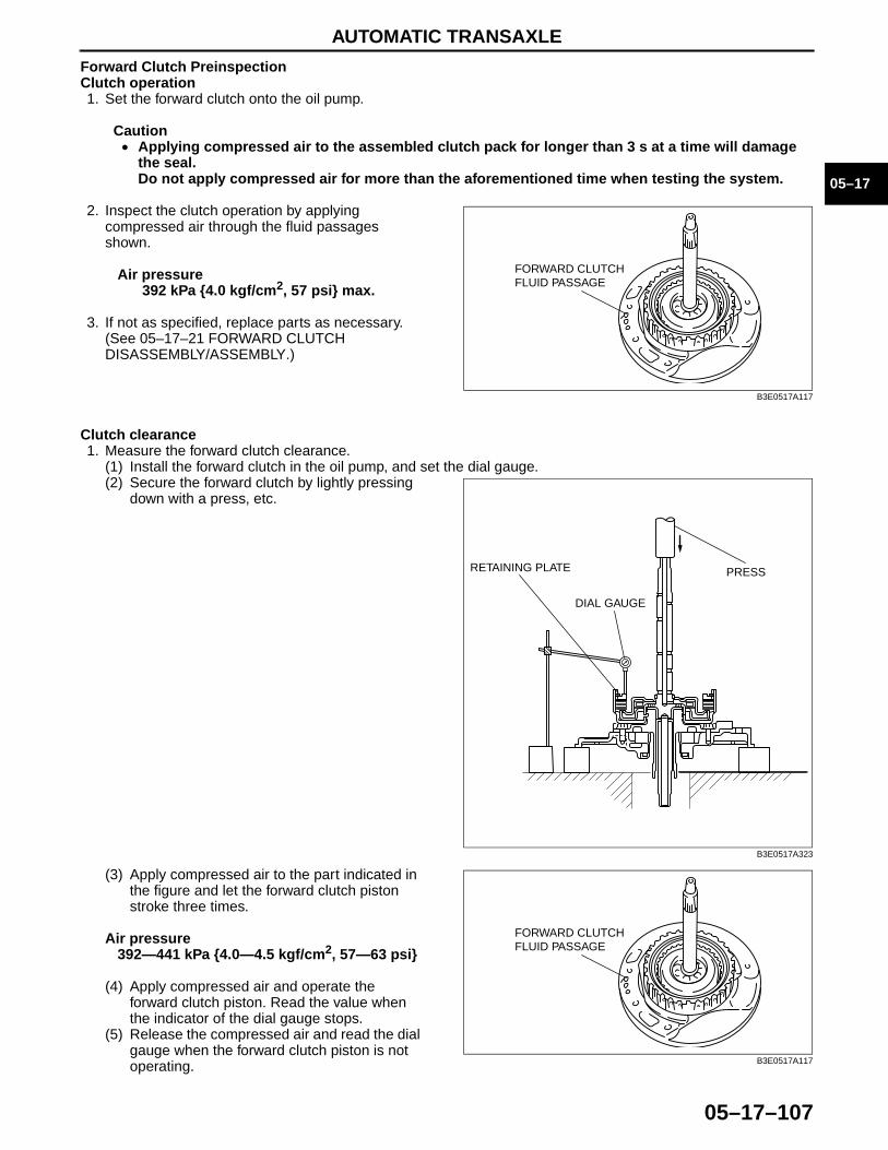
AUTOMATIC TRANSAXLE
05–17–107
05–17
Forward Clutch PreinspectionClutch operation1. Set the forward clutch onto the oil pump.
Caution• Applying compressed air to the assembled clutch pack for longer than 3 s at a time will damage
the seal. Do not apply compressed air for more than the aforementioned time when testing the system.
2. Inspect the clutch operation by applying compressed air through the fluid passages shown.
Air pressure392 kPa {4.0 kgf/cm2, 57 psi} max.
3. If not as specified, replace parts as necessary. (See 05–17–21 FORWARD CLUTCH DISASSEMBLY/ASSEMBLY.)
Clutch clearance1. Measure the forward clutch clearance.
(1) Install the forward clutch in the oil pump, and set the dial gauge.(2) Secure the forward clutch by lightly pressing
down with a press, etc.
(3) Apply compressed air to the part indicated in the figure and let the forward clutch piston stroke three times.
Air pressure392—441 kPa {4.0—4.5 kgf/cm2, 57—63 psi}
(4) Apply compressed air and operate the forward clutch piston. Read the value when the indicator of the dial gauge stops.
(5) Release the compressed air and read the dial gauge when the forward clutch piston is not operating.
FORWARD CLUTCH FLUID PASSAGE
B3E0517A117
PRESS
DIAL GAUGE
RETAINING PLATE
B3E0517A323
FORWARD CLUTCH FLUID PASSAGE
B3E0517A117
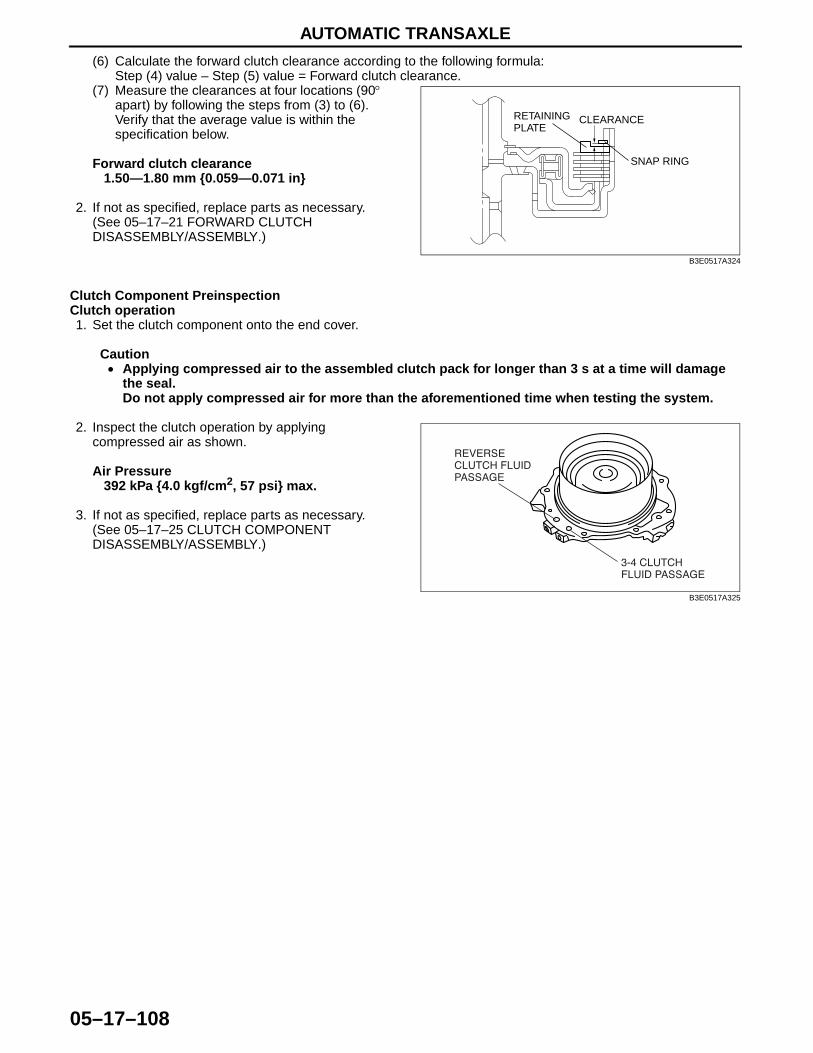
AUTOMATIC TRANSAXLE
05–17–108
(6) Calculate the forward clutch clearance according to the following formula:Step (4) value – Step (5) value = Forward clutch clearance.
(7) Measure the clearances at four locations (90° apart) by following the steps from (3) to (6). Verify that the average value is within the specification below.
Forward clutch clearance1.50—1.80 mm {0.059—0.071 in}
2. If not as specified, replace parts as necessary. (See 05–17–21 FORWARD CLUTCH DISASSEMBLY/ASSEMBLY.)
Clutch Component PreinspectionClutch operation1. Set the clutch component onto the end cover.
Caution• Applying compressed air to the assembled clutch pack for longer than 3 s at a time will damage
the seal.Do not apply compressed air for more than the aforementioned time when testing the system.
2. Inspect the clutch operation by applying compressed air as shown.
Air Pressure392 kPa {4.0 kgf/cm2, 57 psi} max.
3. If not as specified, replace parts as necessary. (See 05–17–25 CLUTCH COMPONENT DISASSEMBLY/ASSEMBLY.)
RETAININGPLATE
CLEARANCE
SNAP RING
B3E0517A324
��� ������
��� � �� ��
�������
������ ���
� �� ��
B3E0517A325
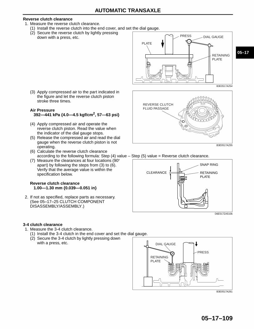
AUTOMATIC TRANSAXLE
05–17–109
05–17
Reverse clutch clearance1. Measure the reverse clutch clearance.
(1) Install the reverse clutch into the end cover, and set the dial gauge.(2) Secure the reverse clutch by lightly pressing
down with a press, etc.
(3) Apply compressed air to the part indicated in the figure and let the reverse clutch piston stroke three times.
Air Pressure392—441 kPa {4.0—4.5 kgf/cm2, 57—63 psi}
(4) Apply compressed air and operate the reverse clutch piston. Read the value when the indicator of the dial gauge stops.
(5) Release the compressed air and read the dial gauge when the reverse clutch piston is not operating.
(6) Calculate the reverse clutch clearance according to the following formula: Step (4) value – Step (5) value = Reverse clutch clearance.
(7) Measure the clearances at four locations (90° apart) by following the steps from (3) to (6). Verify that the average value is within the specification below.
Reverse clutch clearance1.00—1.30 mm {0.039—0.051 in}
2. If not as specified, replace parts as necessary. (See 05–17–25 CLUTCH COMPONENT DISASSEMBLY/ASSEMBLY.)
3-4 clutch clearance1. Measure the 3-4 clutch clearance.
(1) Install the 3-4 clutch in the end cover and set the dial gauge.(2) Secure the 3-4 clutch by lightly pressing down
with a press, etc.
PLATE
PRESS
RETAINING PLATE
DIAL GAUGE
B3E0517A254
REVERSE CLUTCHFLUID PASSAGE
B3E0517A255
SNAP RING
CLEARANCE RETAINING PLATE
D6E517ZA5106
DIAL GAUGE
RETAININGPLATE
PRESS
B3E0517A261
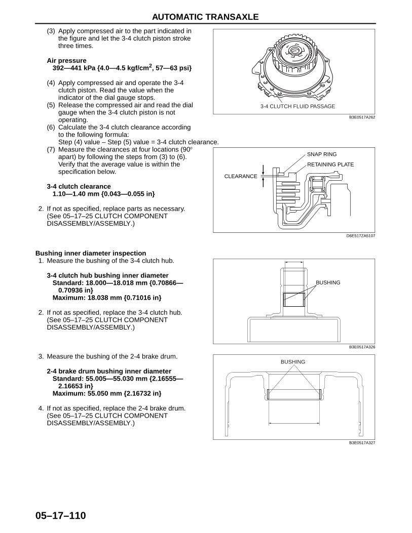
AUTOMATIC TRANSAXLE
05–17–110
(3) Apply compressed air to the part indicated in the figure and let the 3-4 clutch piston stroke three times.
Air pressure392—441 kPa {4.0—4.5 kgf/cm2, 57—63 psi}
(4) Apply compressed air and operate the 3-4 clutch piston. Read the value when the indicator of the dial gauge stops.
(5) Release the compressed air and read the dial gauge when the 3-4 clutch piston is not operating.
(6) Calculate the 3-4 clutch clearance according to the following formula:Step (4) value – Step (5) value = 3-4 clutch clearance.
(7) Measure the clearances at four locations (90° apart) by following the steps from (3) to (6). Verify that the average value is within the specification below.
3-4 clutch clearance1.10—1.40 mm {0.043—0.055 in}
2. If not as specified, replace parts as necessary. (See 05–17–25 CLUTCH COMPONENT DISASSEMBLY/ASSEMBLY.)
Bushing inner diameter inspection1. Measure the bushing of the 3-4 clutch hub.
3-4 clutch hub bushing inner diameterStandard: 18.000—18.018 mm {0.70866—
0.70936 in}Maximum: 18.038 mm {0.71016 in}
2. If not as specified, replace the 3-4 clutch hub. (See 05–17–25 CLUTCH COMPONENT DISASSEMBLY/ASSEMBLY.)
3. Measure the bushing of the 2-4 brake drum.
2-4 brake drum bushing inner diameterStandard: 55.005—55.030 mm {2.16555—
2.16653 in}Maximum: 55.050 mm {2.16732 in}
4. If not as specified, replace the 2-4 brake drum. (See 05–17–25 CLUTCH COMPONENT DISASSEMBLY/ASSEMBLY.)
3-4 CLUTCH FLUID PASSAGE
B3E0517A262
SNAP RING
CLEARANCE
RETAINING PLATE
D6E517ZA5107
BUSHING
B3E0517A326
BUSHING
B3E0517A327

AUTOMATIC TRANSAXLE
05–17–111
05–17
Front Internal Gear and One-Way Clutch No.1 ComponentPreinspection1. Set the front internal gear and one-way clutch
No.1 component to the one-way clutch inner race. Verify that the one-way clutch rotates smoothly when turned counterclockwise and locks when turned clockwise.
2. If not as specified, replace parts as necessary. (See 05–17–34 FRONT INTERNAL GEAR ONE-WAY CLUTCH NO.1 COMPONENT DISASSEMBLY/ASSEMBLY.)
Low and Reverse Brake PreinspectionBrake operation
Caution• Applying compressed air to the assembled clutch pack for longer than 3 s at a time will damage
the seal.Do not apply compressed air for more than the aforementioned time when testing the system.
1. Inspect the brake operation by applying compressed air as shown.
Air pressure392 kPa {4.0 kgf/cm2, 57 psi} max.
2. If not as specified, replace parts as necessary. (See 05–17–37 LOW AND REVERSE BRAKE AND ONE-WAY CLUTCH INNER RACE DISASSEMBLY/ASSEMBLY.)
Brake clearance1. Measure the low and reverse brake clearance.
(1) Set the dial gauge to the low and reverse brake.(2) Set the measuring point of the dial gauge to
the low and reverse brake piston.
GOOD NO GOOD
D6E517ZA5104
LOW AND REVERSE BRAKE FLUID PASSAGE
D6E517ZA5043
DIAL GAUGE
LOW AND REVERSE BRAKE PISTON
B3E0517A329
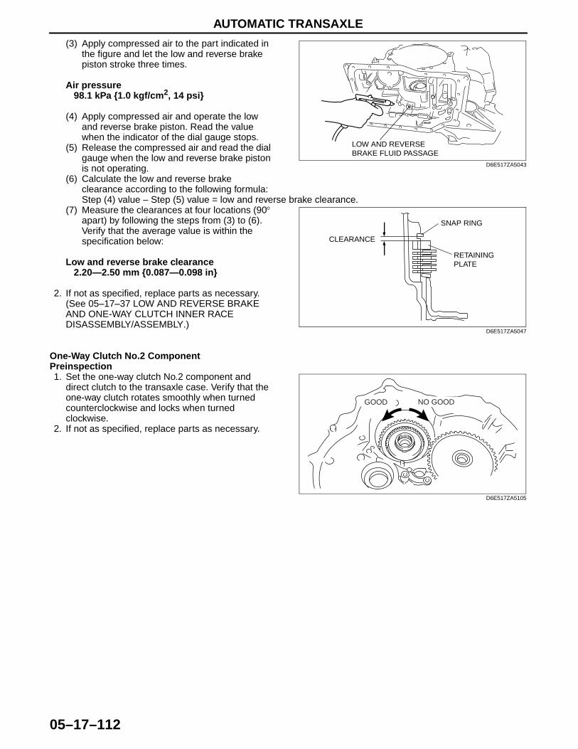
AUTOMATIC TRANSAXLE
05–17–112
(3) Apply compressed air to the part indicated in the figure and let the low and reverse brake piston stroke three times.
Air pressure98.1 kPa {1.0 kgf/cm2, 14 psi}
(4) Apply compressed air and operate the low and reverse brake piston. Read the value when the indicator of the dial gauge stops.
(5) Release the compressed air and read the dial gauge when the low and reverse brake piston is not operating.
(6) Calculate the low and reverse brake clearance according to the following formula:Step (4) value – Step (5) value = low and reverse brake clearance.
(7) Measure the clearances at four locations (90° apart) by following the steps from (3) to (6). Verify that the average value is within the specification below:
Low and reverse brake clearance2.20—2.50 mm {0.087—0.098 in}
2. If not as specified, replace parts as necessary. (See 05–17–37 LOW AND REVERSE BRAKE AND ONE-WAY CLUTCH INNER RACE DISASSEMBLY/ASSEMBLY.)
One-Way Clutch No.2 ComponentPreinspection1. Set the one-way clutch No.2 component and
direct clutch to the transaxle case. Verify that the one-way clutch rotates smoothly when turned counterclockwise and locks when turned clockwise.
2. If not as specified, replace parts as necessary.
LOW AND REVERSE BRAKE FLUID PASSAGE
D6E517ZA5043
SNAP RING
CLEARANCE
RETAINING PLATE
D6E517ZA5047
GOOD NO GOOD
D6E517ZA5105

AUTOMATIC TRANSAXLE
05–17–113
05–17
Direct Clutch PreinspectionClutch operation1. Set the direct clutch drum onto the transaxle case.
Caution• Applying compressed air to the assembled clutch pack for longer than 3 s at a time will damage
the seal.Do not apply compressed air for more than the aforementioned time when testing the system.
2. Inspect the clutch operation by applying compressed air as shown.
Air pressure392—441 kPa {4.0—4.5 kgf/cm2, 57—63 psi}
3. If not as specified, replace parts as necessary. (See 05–17–41 DIRECT CLUTCH DISASSEMBLY/ASSEMBLY.)
Clutch clearanceMeasure the direct clutch clearance.1. Install the direct clutch in the transaxle case, and set the dial gauge.2. Secure the direct clutch by lightly pressing down
with a press or similar tool.
3. Apply compressed air to the part indicated in the figure and let the direct clutch piston stroke three times.
Air pressure392—441 kPa {4.0—4.5 kgf/cm2, 57—63 psi}
DIRECT CLUTCH FLUID PASSAGE
D6E517ZA5050
RETAININGPLATE
PRESSDIAL GAUGE
D6E517ZA5052
DIRECT CLUTCH FLUID PASSAGE
D6E517ZA5050
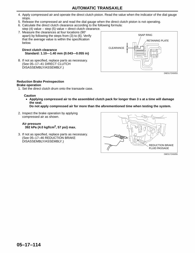
AUTOMATIC TRANSAXLE
05–17–114
4. Apply compressed air and operate the direct clutch piston. Read the value when the indicator of the dial gauge stops.
5. Release the compressed air and read the dial gauge when the direct clutch piston is not operating.6. Calculate the direct clutch clearance according to the following formula:
step (4) value – step (5) value = direct clutch clearance.7. Measure the clearances at four locations (90°
apart) by following the steps from (3) to (6). Verify that the average value is within the specification below.
Direct clutch clearanceStandard: 1.10—1.40 mm {0.043—0.055 in}
8. If not as specified, replace parts as necessary. (See 05–17–41 DIRECT CLUTCH DISASSEMBLY/ASSEMBLY.)
Reduction Brake PreinspectionBrake operation1. Set the direct clutch drum onto the transaxle case.
Caution• Applying compressed air to the assembled clutch pack for longer than 3 s at a time will damage
the seal.Do not apply compressed air for more than the aforementioned time when testing the system.
2. Inspect the brake operation by applying compressed air as shown.
Air pressure392 kPa {4.0 kgf/cm2, 57 psi} max.
3. If not as specified, replace parts as necessary. (See 05–17–46 REDUCTION BRAKE DISASSEMBLY/ASSEMBLY.)
SNAP RING
CLEARANCE
RETAINING PLATE
D6E517ZA5053
REDUCTION BRAKE FLUID PASSAGE
D6E517ZA5055
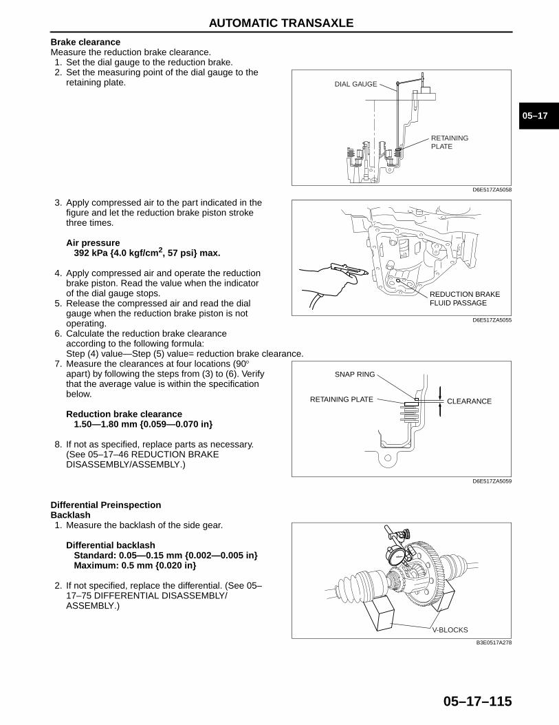
AUTOMATIC TRANSAXLE
05–17–115
05–17
Brake clearanceMeasure the reduction brake clearance.1. Set the dial gauge to the reduction brake.2. Set the measuring point of the dial gauge to the
retaining plate.
3. Apply compressed air to the part indicated in the figure and let the reduction brake piston stroke three times.
Air pressure392 kPa {4.0 kgf/cm2, 57 psi} max.
4. Apply compressed air and operate the reduction brake piston. Read the value when the indicator of the dial gauge stops.
5. Release the compressed air and read the dial gauge when the reduction brake piston is not operating.
6. Calculate the reduction brake clearance according to the following formula:Step (4) value—Step (5) value= reduction brake clearance.
7. Measure the clearances at four locations (90° apart) by following the steps from (3) to (6). Verify that the average value is within the specification below.
Reduction brake clearance1.50—1.80 mm {0.059—0.070 in}
8. If not as specified, replace parts as necessary. (See 05–17–46 REDUCTION BRAKE DISASSEMBLY/ASSEMBLY.)
Differential PreinspectionBacklash1. Measure the backlash of the side gear.
Differential backlashStandard: 0.05—0.15 mm {0.002—0.005 in}Maximum: 0.5 mm {0.020 in}
2. If not specified, replace the differential. (See 05–17–75 DIFFERENTIAL DISASSEMBLY/ASSEMBLY.)
End Of Sie
RETAININGPLATE
DIAL GAUGE
D6E517ZA5058
REDUCTION BRAKE FLUID PASSAGE
D6E517ZA5055
SNAP RING
CLEARANCERETAINING PLATE
D6E517ZA5059
V-BLOCKS
B3E0517A278

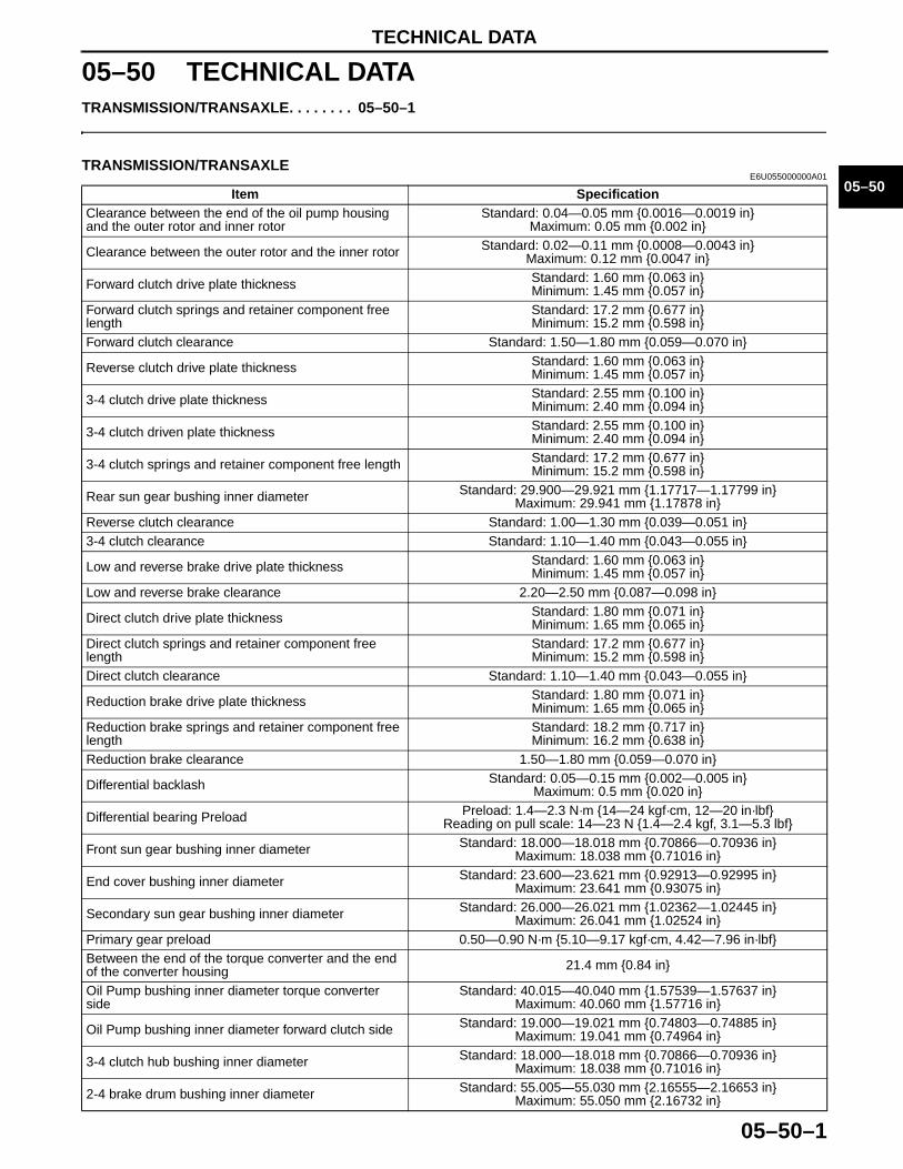
TECHNICAL DATA
05–50–1
05–50
05–50 TECHNICAL DATATRANSMISSION/TRANSAXLE. . . . . . . . 05–50–1
End of Toc
TRANSMISSION/TRANSAXLEE6U055000000A01
Item SpecificationClearance between the end of the oil pump housing and the outer rotor and inner rotor
Standard: 0.04—0.05 mm {0.0016—0.0019 in}Maximum: 0.05 mm {0.002 in}
Clearance between the outer rotor and the inner rotor Standard: 0.02—0.11 mm {0.0008—0.0043 in}Maximum: 0.12 mm {0.0047 in}
Forward clutch drive plate thickness Standard: 1.60 mm {0.063 in}Minimum: 1.45 mm {0.057 in}
Forward clutch springs and retainer component free length
Standard: 17.2 mm {0.677 in}Minimum: 15.2 mm {0.598 in}
Forward clutch clearance Standard: 1.50—1.80 mm {0.059—0.070 in}
Reverse clutch drive plate thickness Standard: 1.60 mm {0.063 in}Minimum: 1.45 mm {0.057 in}
3-4 clutch drive plate thickness Standard: 2.55 mm {0.100 in}Minimum: 2.40 mm {0.094 in}
3-4 clutch driven plate thickness Standard: 2.55 mm {0.100 in}Minimum: 2.40 mm {0.094 in}
3-4 clutch springs and retainer component free length Standard: 17.2 mm {0.677 in}Minimum: 15.2 mm {0.598 in}
Rear sun gear bushing inner diameter Standard: 29.900—29.921 mm {1.17717—1.17799 in}Maximum: 29.941 mm {1.17878 in}
Reverse clutch clearance Standard: 1.00—1.30 mm {0.039—0.051 in} 3-4 clutch clearance Standard: 1.10—1.40 mm {0.043—0.055 in}
Low and reverse brake drive plate thickness Standard: 1.60 mm {0.063 in}Minimum: 1.45 mm {0.057 in}
Low and reverse brake clearance 2.20—2.50 mm {0.087—0.098 in}
Direct clutch drive plate thickness Standard: 1.80 mm {0.071 in}Minimum: 1.65 mm {0.065 in}
Direct clutch springs and retainer component free length
Standard: 17.2 mm {0.677 in}Minimum: 15.2 mm {0.598 in}
Direct clutch clearance Standard: 1.10—1.40 mm {0.043—0.055 in}
Reduction brake drive plate thickness Standard: 1.80 mm {0.071 in}Minimum: 1.65 mm {0.065 in}
Reduction brake springs and retainer component free length
Standard: 18.2 mm {0.717 in}Minimum: 16.2 mm {0.638 in}
Reduction brake clearance 1.50—1.80 mm {0.059—0.070 in}
Differential backlash Standard: 0.05—0.15 mm {0.002—0.005 in}Maximum: 0.5 mm {0.020 in}
Differential bearing Preload Preload: 1.4—2.3 N·m {14—24 kgf·cm, 12—20 in·lbf}Reading on pull scale: 14—23 N {1.4—2.4 kgf, 3.1—5.3 lbf}
Front sun gear bushing inner diameter Standard: 18.000—18.018 mm {0.70866—0.70936 in}Maximum: 18.038 mm {0.71016 in}
End cover bushing inner diameter Standard: 23.600—23.621 mm {0.92913—0.92995 in}Maximum: 23.641 mm {0.93075 in}
Secondary sun gear bushing inner diameter Standard: 26.000—26.021 mm {1.02362—1.02445 in}Maximum: 26.041 mm {1.02524 in}
Primary gear preload 0.50—0.90 N·m {5.10—9.17 kgf·cm, 4.42—7.96 in·lbf}Between the end of the torque converter and the end of the converter housing 21.4 mm {0.84 in}
Oil Pump bushing inner diameter torque converter side
Standard: 40.015—40.040 mm {1.57539—1.57637 in}Maximum: 40.060 mm {1.57716 in}
Oil Pump bushing inner diameter forward clutch side Standard: 19.000—19.021 mm {0.74803—0.74885 in}Maximum: 19.041 mm {0.74964 in}
3-4 clutch hub bushing inner diameter Standard: 18.000—18.018 mm {0.70866—0.70936 in}Maximum: 18.038 mm {0.71016 in}
2-4 brake drum bushing inner diameter Standard: 55.005—55.030 mm {2.16555—2.16653 in}Maximum: 55.050 mm {2.16732 in}
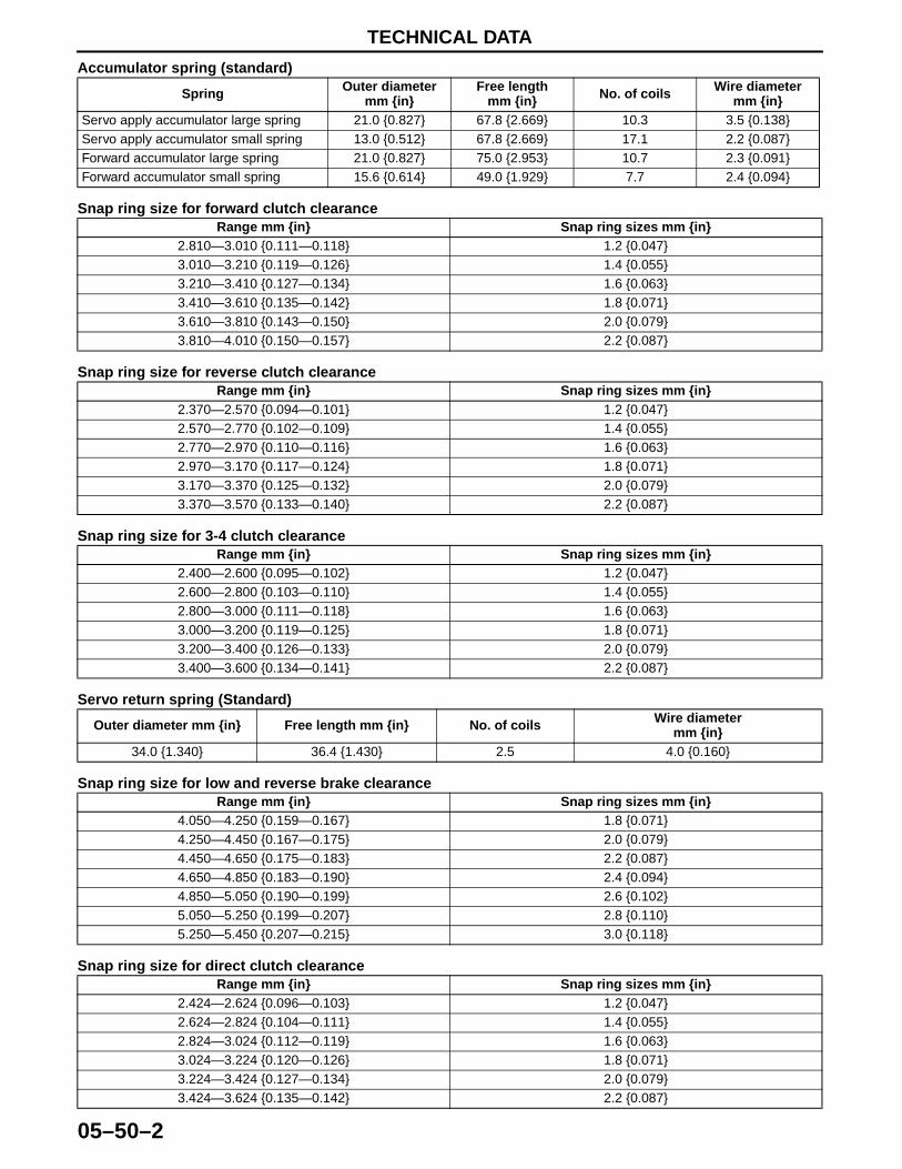
TECHNICAL DATA
05–50–2
Accumulator spring (standard)
Snap ring size for forward clutch clearance
Snap ring size for reverse clutch clearance
Snap ring size for 3-4 clutch clearance
Servo return spring (Standard)
Snap ring size for low and reverse brake clearance
Snap ring size for direct clutch clearance
Spring Outer diameter mm {in}
Free length mm {in} No. of coils Wire diameter
mm {in}Servo apply accumulator large spring 21.0 {0.827} 67.8 {2.669} 10.3 3.5 {0.138}Servo apply accumulator small spring 13.0 {0.512} 67.8 {2.669} 17.1 2.2 {0.087}Forward accumulator large spring 21.0 {0.827} 75.0 {2.953} 10.7 2.3 {0.091}Forward accumulator small spring 15.6 {0.614} 49.0 {1.929} 7.7 2.4 {0.094}
Range mm {in} Snap ring sizes mm {in}2.810—3.010 {0.111—0.118} 1.2 {0.047}3.010—3.210 {0.119—0.126} 1.4 {0.055}3.210—3.410 {0.127—0.134} 1.6 {0.063}3.410—3.610 {0.135—0.142} 1.8 {0.071}3.610—3.810 {0.143—0.150} 2.0 {0.079}3.810—4.010 {0.150—0.157} 2.2 {0.087}
Range mm {in} Snap ring sizes mm {in}2.370—2.570 {0.094—0.101} 1.2 {0.047}2.570—2.770 {0.102—0.109} 1.4 {0.055}2.770—2.970 {0.110—0.116} 1.6 {0.063}2.970—3.170 {0.117—0.124} 1.8 {0.071}3.170—3.370 {0.125—0.132} 2.0 {0.079}3.370—3.570 {0.133—0.140} 2.2 {0.087}
Range mm {in} Snap ring sizes mm {in}2.400—2.600 {0.095—0.102} 1.2 {0.047}2.600—2.800 {0.103—0.110} 1.4 {0.055}2.800—3.000 {0.111—0.118} 1.6 {0.063}3.000—3.200 {0.119—0.125} 1.8 {0.071}3.200—3.400 {0.126—0.133} 2.0 {0.079}3.400—3.600 {0.134—0.141} 2.2 {0.087}
Outer diameter mm {in} Free length mm {in} No. of coils Wire diametermm {in}
34.0 {1.340} 36.4 {1.430} 2.5 4.0 {0.160}
Range mm {in} Snap ring sizes mm {in}4.050—4.250 {0.159—0.167} 1.8 {0.071}4.250—4.450 {0.167—0.175} 2.0 {0.079}4.450—4.650 {0.175—0.183} 2.2 {0.087}4.650—4.850 {0.183—0.190} 2.4 {0.094}4.850—5.050 {0.190—0.199} 2.6 {0.102}5.050—5.250 {0.199—0.207} 2.8 {0.110}5.250—5.450 {0.207—0.215} 3.0 {0.118}
Range mm {in} Snap ring sizes mm {in}2.424—2.624 {0.096—0.103} 1.2 {0.047}2.624—2.824 {0.104—0.111} 1.4 {0.055}2.824—3.024 {0.112—0.119} 1.6 {0.063}3.024—3.224 {0.120—0.126} 1.8 {0.071}3.224—3.424 {0.127—0.134} 2.0 {0.079}3.424—3.624 {0.135—0.142} 2.2 {0.087}
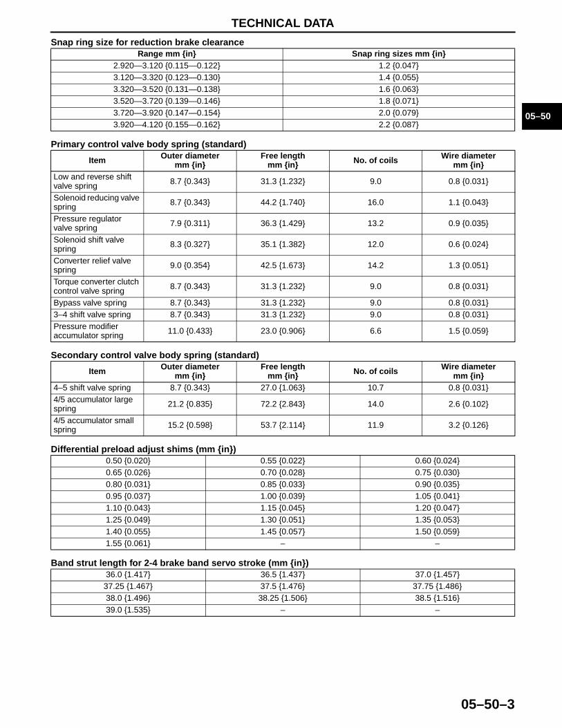
TECHNICAL DATA
05–50–3
05–50
Snap ring size for reduction brake clearance
Primary control valve body spring (standard)
Secondary control valve body spring (standard)
Differential preload adjust shims (mm {in})
Band strut length for 2-4 brake band servo stroke (mm {in})
Range mm {in} Snap ring sizes mm {in}2.920—3.120 {0.115—0.122} 1.2 {0.047}3.120—3.320 {0.123—0.130} 1.4 {0.055}3.320—3.520 {0.131—0.138} 1.6 {0.063}3.520—3.720 {0.139—0.146} 1.8 {0.071}3.720—3.920 {0.147—0.154} 2.0 {0.079}3.920—4.120 {0.155—0.162} 2.2 {0.087}
Item Outer diametermm {in}
Free lengthmm {in} No. of coils Wire diameter
mm {in}Low and reverse shift valve spring 8.7 {0.343} 31.3 {1.232} 9.0 0.8 {0.031}
Solenoid reducing valve spring 8.7 {0.343} 44.2 {1.740} 16.0 1.1 {0.043}
Pressure regulator valve spring 7.9 {0.311} 36.3 {1.429} 13.2 0.9 {0.035}
Solenoid shift valve spring 8.3 {0.327} 35.1 {1.382} 12.0 0.6 {0.024}
Converter relief valve spring 9.0 {0.354} 42.5 {1.673} 14.2 1.3 {0.051}
Torque converter clutch control valve spring 8.7 {0.343} 31.3 {1.232} 9.0 0.8 {0.031}
Bypass valve spring 8.7 {0.343} 31.3 {1.232} 9.0 0.8 {0.031}3–4 shift valve spring 8.7 {0.343} 31.3 {1.232} 9.0 0.8 {0.031}Pressure modifier accumulator spring 11.0 {0.433} 23.0 {0.906} 6.6 1.5 {0.059}
Item Outer diametermm {in}
Free lengthmm {in} No. of coils Wire diameter
mm {in}4–5 shift valve spring 8.7 {0.343} 27.0 {1.063} 10.7 0.8 {0.031}4/5 accumulator large spring 21.2 {0.835} 72.2 {2.843} 14.0 2.6 {0.102}
4/5 accumulator small spring 15.2 {0.598} 53.7 {2.114} 11.9 3.2 {0.126}
0.50 {0.020} 0.55 {0.022} 0.60 {0.024}0.65 {0.026} 0.70 {0.028} 0.75 {0.030}0.80 {0.031} 0.85 {0.033} 0.90 {0.035}0.95 {0.037} 1.00 {0.039} 1.05 {0.041}1.10 {0.043} 1.15 {0.045} 1.20 {0.047}1.25 {0.049} 1.30 {0.051} 1.35 {0.053}1.40 {0.055} 1.45 {0.057} 1.50 {0.059}1.55 {0.061} – –
36.0 {1.417} 36.5 {1.437} 37.0 {1.457}37.25 {1.467} 37.5 {1.476} 37.75 {1.486}38.0 {1.496} 38.25 {1.506} 38.5 {1.516}39.0 {1.535} – –
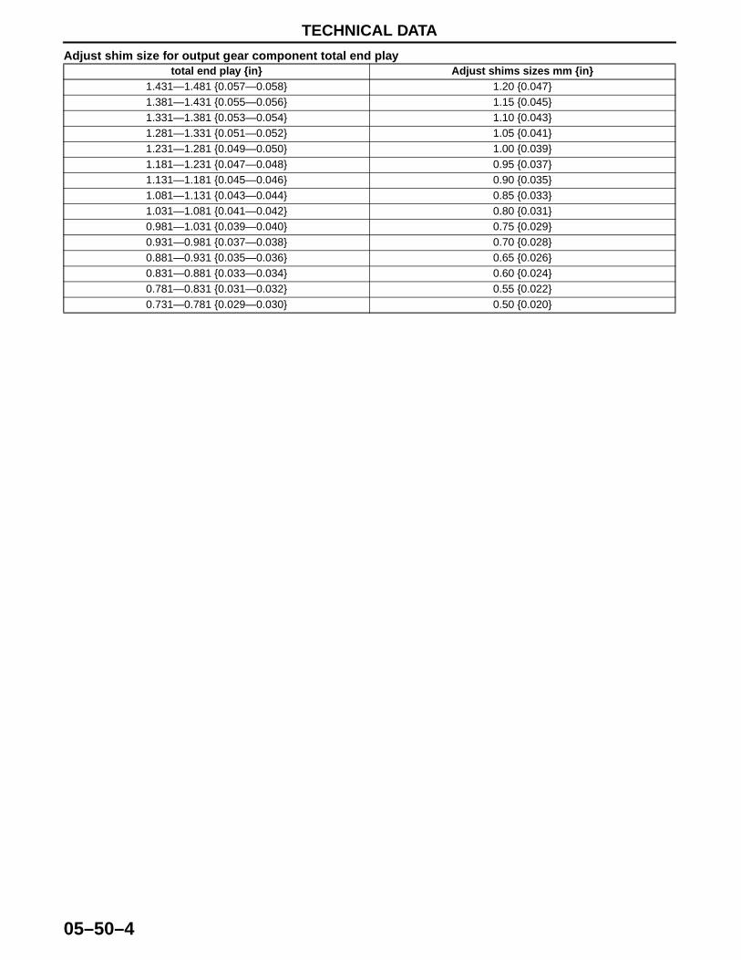
TECHNICAL DATA
05–50–4
Adjust shim size for output gear component total end play
End Of Sie
total end play {in} Adjust shims sizes mm {in}1.431—1.481 {0.057—0.058} 1.20 {0.047}1.381—1.431 {0.055—0.056} 1.15 {0.045}1.331—1.381 {0.053—0.054} 1.10 {0.043}1.281—1.331 {0.051—0.052} 1.05 {0.041}1.231—1.281 {0.049—0.050} 1.00 {0.039}1.181—1.231 {0.047—0.048} 0.95 {0.037}1.131—1.181 {0.045—0.046} 0.90 {0.035}1.081—1.131 {0.043—0.044} 0.85 {0.033}1.031—1.081 {0.041—0.042} 0.80 {0.031}0.981—1.031 {0.039—0.040} 0.75 {0.029}0.931—0.981 {0.037—0.038} 0.70 {0.028}0.881—0.931 {0.035—0.036} 0.65 {0.026}0.831—0.881 {0.033—0.034} 0.60 {0.024}0.781—0.831 {0.031—0.032} 0.55 {0.022}0.731—0.781 {0.029—0.030} 0.50 {0.020}
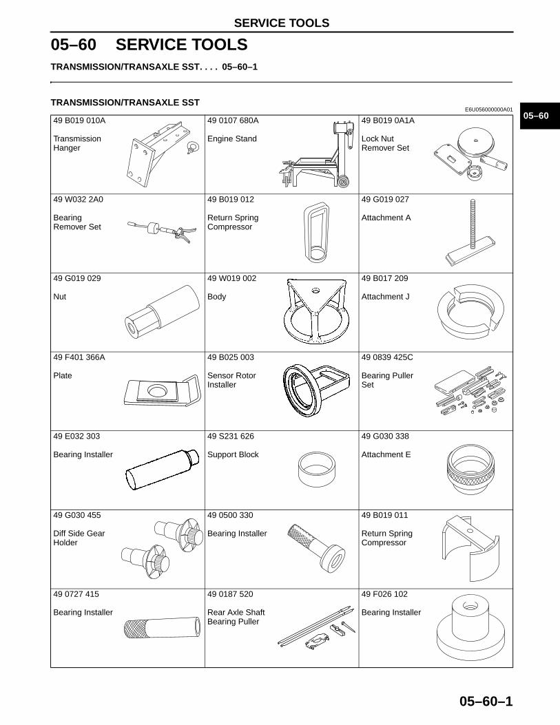
SERVICE TOOLS
05–60–1
05–60
05–60 SERVICE TOOLSTRANSMISSION/TRANSAXLE SST. . . . 05–60–1
End of Toc
TRANSMISSION/TRANSAXLE SSTE6U056000000A01
49 B019 010A
Transmission Hanger
49 0107 680A
Engine Stand
49 B019 0A1A
Lock Nut Remover Set
49 W032 2A0
Bearing Remover Set
49 B019 012
Return Spring Compressor
49 G019 027
Attachment A
49 G019 029
Nut
49 W019 002
Body
49 B017 209
Attachment J
49 F401 366A
Plate
49 B025 003
Sensor Rotor Installer
49 0839 425C
Bearing Puller Set
49 E032 303
Bearing Installer
49 S231 626
Support Block
49 G030 338
Attachment E
49 G030 455
Diff Side Gear Holder
49 0500 330
Bearing Installer
49 B019 011
Return Spring Compressor
49 0727 415
Bearing Installer
49 0187 520
Rear Axle Shaft Bearing Puller
49 F026 102
Bearing Installer
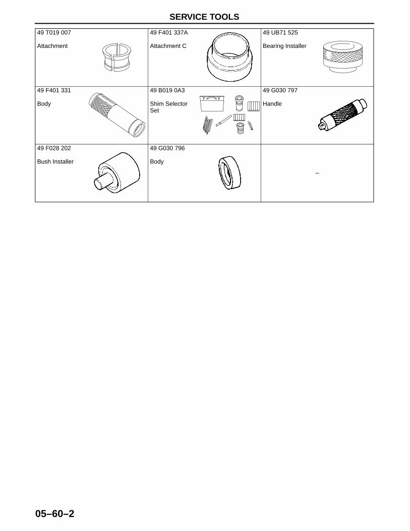
SERVICE TOOLS
05–60–2
End Of Sie
49 T019 007
Attachment
49 F401 337A
Attachment C
49 UB71 525
Bearing Installer
49 F401 331
Body
49 B019 0A3
Shim Selector Set
49 G030 797
Handle
49 F028 202
Bush Installer
49 G030 796
Body
–