frp for prestressing of concrete bridges in canada · pdf filefrp for prestressing of concrete...
TRANSCRIPT

Rizkalla, S., and Tadros, G., “FRP for Prestressing of Concrete Bridges in Canada,”Page 1
FRP for Prestressing of Concrete Bridges in Canada
Sami Rizkalla and Gamil Tadros
Synopsis This paper describes the use of Carbon Fiber Reinforced Polymer, CFRP, tendons and rods for prestressing concrete highway bridges completed in 1993 and 1997. Due to the lack of design codes, the paper presents briefly the research work undertaken before the final design of the two bridges. The first bridge is a 75 ft. (23.85 m) span skew bridge, which consists of bulb-tee pre-tensioned girders made continuous with post-tensioned steel strands. Four girders were pre-tensioned by two types of CFRP. The second bridge is 541 ft. (165 m) long and consists of five simply supported span girders, 110 ft. (33 m) long. Four girders were prestressed by two different types of CFRP using straight and draped tendons. The AASHTO girders were also reinforced with CFRP stirrups. A portion of the deck slab is reinforced by CFRP reinforcement. Design considerations, safety features and construction of each bridge are described briefly. The paper summarizes also the results of monitoring the behavior of each bridge. The experience gained from these two bridges provides valuable information for the development of the design guidelines, currently under consideration by the ACI Committee 440, Fiber Reinforced Polymer. Keywords: Bridge, caron fibers, prestressing, concrete, safety, monitoring, optic fibers.
Rizkalla, S., and Tadros, G., “FRP for Prestressing of Concrete Bridges in Canada,”Page 2
Sami Rizkalla: FACI, is Distinguished Professor of Civil Engineering and Construction, Director of the Constructed Facilities Laboratory, North Carolina State University. He is Chairman of ACI Committee 440, Fiber Reinforced Polymer, member of the ACI-ASCE joint Committee 550, Precast Concrete Structures and a member of ACI Committee 423, Prestressed Concrete. Gamil Tadros: MACI, is Technical Applications Consultant, ISIS Canada and Structural Consultant, Speco Engineering Ltd. Dr. Tadros is an active member in Canadian Codes for the use of FRP. His field of activity includes bridge analysis, rehabilitation, and design, structural analysis, prestressed concrete, and FRP design. He is a member of ACI Committee 440, Fiber Reinforced Polymer.
INTRODUCTION During the last two decades, fiber reinforced polymer (FRP) materials have been used in a variety of configurations as an alternative reinforcement for new and strengthening civil engineering structures and bridges. The attractiveness of the material lies mainly in their high corrosion resistance, high strength and fatigue resistance. In some cases, the non-magnetic characteristics became more important for some special structures. This paper focuses on the Canadian experience in the use of FRP as prestressing reinforcement for concrete highway bridges. The two bridges described in this paper were built in 1993 and 1997 and monitored to examine the long-term behavior of FRP as prestressing reinforcement in severe environment and under normal traffic conditions. Brief summaries of the research work conducted by testing scale models to simulate the behavior of the girder and the deck slab are presented. Design considerations and details of the safety features used for each bridge are provided. The paper describes construction of the precast girder and the methodology used for prestressing the FRP tendons and rods. Test results of recent field testing of the bridges under truck loads are also presented.
SIGNIFICANCE OF RESEARCH The experience gained by design, prestressing of bridge girders and construction of prestressed concrete highway bridges provides important data for the development of the design guidelines currently under consideration by ACI 440 on FRP. The long-term performance of FRP prestressing tendons and bars, obtained by field monitoring, provides also unique data on the durability and serviceability of these types of FRP prestressing reinforcements subjected to field loading and environmental conditions. The safety features, implemented into the two bridges provide design engineers with useful concepts, which can be used to add on additional safety factors due to the limited experience in using these relatively new types of prestressing.
BEDDINGTON TRAIL/CENTRE STREET BRIDGE This bridge is the first prestressed concrete highway bridge built in Calgary, Canada and was completed in 1993. The bridge is a two span skew bridge made continuous for live load. The bridge has 75 feet (22.83 m) and 63 feet (19.23 m) spans consisting of 13 bulb-tee precast girders composite with 6 inches (150 mm) thick concrete deck in each span as shown in Fig. (1).

Rizkalla, S., and Tadros, G., “FRP for Prestressing of Concrete Bridges in Canada,”Page 3
Post-tensioned Steel TendonsPre-tensioned Carbon Strands
650
160
1500
1100
15
0 10
0 56
0 50
100
14
0
Row for Additional Strands
Dimensions in “ mm”
Fig (2) Girder cross-section
22.85m 19.23m
33.33º Middle Pier
Abutment 13 Bulb T-Section Girders Abutment
App
roac
h Sl
ab
App
roac
h Sl
ab
Fig (1) Bridge Layout
The bridge acts as a simply supported span for its own weight and the weight of deck slab. Each girder is pre-tensioned with 26 or 22-1/2” (12.7 mm) diameter steel strands to resist these loads. The two simple spans made continuous with post-tensioning consisting of 12-1/2” (12.7 mm) 7 wire strands. Four of the twenty-six bulb-tee precast girders were pre-tensioned by two types of CFRP tendons. Four of these girders were pre-tensioned using Carbon Fiber Composite Cables (CFCC), 5/8” (15.2 mm) in diameter, produced by Tokyo Rope, Japan. The other two girders were pre-tensioned using 5/16” (8 mm) Leadline bars, produced by Mitsubishi Kasei, Japan. Fig. 2 shows the configuration of the CFRP pre-tensioned strands used in the bulb-tee girder. The CFCC strand has an area of 0.176 in 2 (113.6 mm2). The cable is produced using carbon fibers of polyacrylonitrile (PAN) type and epoxy resin [1]. The guaranteed ultimate tensile strength is 250 ksi (1750 MPa), while the tensile elastic modulus is 20,000 ksi (137 GPa). The average measured tensile strength, strain and elastic modulus based on six samples are 310 ksi (2150 MPa), 1.6 percent and 19,400 ksi (137 GPa), respectively. The linear density is 0.15 lb/ft (227 g/m) compared to 0.65 lb/ft (967 g/m) for steel. The Leadline bar has an area of 0.073 in 2 (47.3 mm2). The guaranteed ultimate tensile strength, strain and tensile elastic modulus are 285 ksi (1970 MPa), 1.3 percent and 21,300 ksi (147 GPa), respectively [2]. The linear density is 0.05 lb/ft (77 g/m). The concrete compressive strength was 6,500 psi (45 MPa) at 28 days and 4,200 psi (30 MPa) at time of jacking the tendons. Design Consideration and Safety Features The main girders of Beddington Trail Bridge are pre-tensioned for dead load and post-tensioned for live loads. The aim is to replace the steel tendons with CFRP tendons to examine their behavior under typical environmental and loading conditions. The options available to the authors, at the time, were to substitute the pre-tensioned tendons and/or post-tensioned tendons. The replacement of the pre-tensioned strand will depend only on the bond characteristic of the tendons, while substituting the post-tensioning tendons requires investigating the method and reliability of the anchorage systems. Since it was the first bridge ever built, the authors decided to replace the steel pre-tensioned tendons only with CFRP tendons. A multi-channel fiber optic sensing system was used to monitor the behavior of the bridge by measuring the strains of the CFRP tendons. In case of the unlikely event of possible distress of CFRP tendons, safety features were included [3]. One safety feature in this project is provided by adding holes in the web to support an anchorage for external post-tension tendons, if required, as shown in Fig. (3).

Rizkalla, S., and Tadros, G., “FRP for Prestressing of Concrete Bridges in Canada,”Page 4
holes
Fig. (3) Holes in the web used as safety features Research Components of the Project The behavior of the bridge was investigated by testing four concrete T-beams. The beams had total length of 21 ft. (6.3 m) and depth of 13 inches (330 mm). These tested beams were one-third in scale to the girders of the bridge. Two of the tested beams were pre-tensioned by four 5/16 (8 mm) diameter Leadline bars and the other two beams were pre-tensioned by 5/8” (15.2 mm) CFCC cables. One beam from each group was tested under static loading conditions. Prior to the predicted failure loads, the beams were unloaded to examine the residual deformations and were reloaded up to failure. The other beam from each group was tested under cyclic loading with maximum load equal to the cracking load and minimum load equal to 70 percent of the cracking loads. The beams were tested under load control using sinusoidal wave at 1 Hz up to two million cycles. After the completion of cyclic loading, the beams were tested statically to failure. Experimental Results A complete report of the test results can be found in reference [4]. The two beams prestressed by Leadline and CFCC, tested under static loading conditions, behaved linearly up to cracking and after cracking with reduced stiffness up to failure, as shown in Fig. (4). After unloading and reloading, the behavior of the beams was elastic and the permanent deflection was negligible. The stiffness of the beams after reloading were identical to the initial loading. The beam prestressed by CFCC tested under cyclic loading, showed elastic response for two million cycles. This is attributed to the elastic behavior of the CFCC. The camber of the beam prestressed by CFCC after the completion of two million cycles was equal to the camber before the application of the cyclic loading. This indicates no loss of stiffness due to cyclic loading. The beam was loaded to failure after completion of the two million cycles. The beams followed the same path as the one tested under static loads. The measured load and deflection at failure were 0.95 and 0.9 of the failure load and corresponding deflection of the beam tested under static conditions, respectively.

Rizkalla, S., and Tadros, G., “FRP for Prestressing of Concrete Bridges in Canada,”Page 5
Loa
d (k
N)
Deflection (mm)
Experimental Predicted
0 10 20 30 40 50 60 70 80 90 100 110 120
100
90
80
70
60
50
40
30
20
10
0
Fig. (4) Behavior of the tested beam prestressed with Tokyo Rope
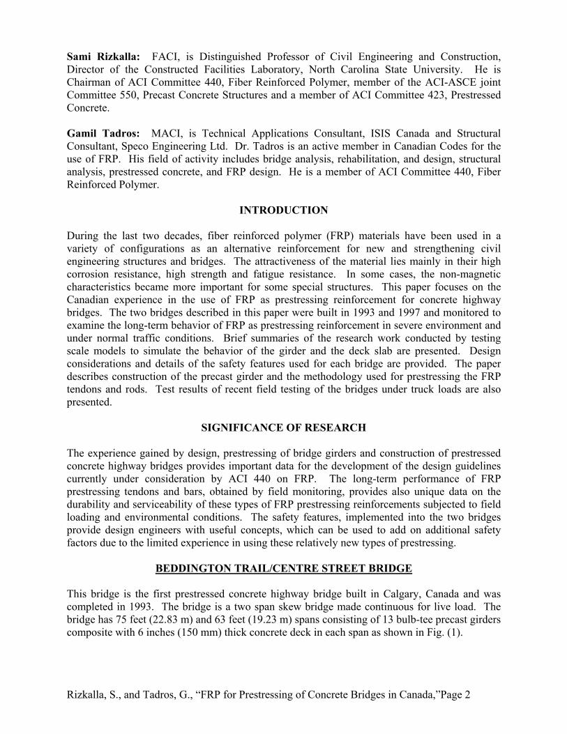
Construction of the Bridge The two prestressing materials are produced and shipped from Japan. Prestressing was adapted to practice by splicing the composite material between two pieces of steel strands using steel couplers as shown in Fig. (5). Applying this method allowed to use the same prestressing equipment and minimized the length, consequently the cost of the FRP reinforcements. Prestressing of all the strands for the typical girder is shown in Fig. (6). The completed bridge is shown in Fig. (7).
Fig. (5) Steel coupler used for prestressing
Fig. (6) Prestressing bed for the bulb-tee girder
Rizkalla, S., and Tadros, G., “FRP for Prestressing of Concrete Bridges in Canada,”Page 6
Fig. (7) Completed bridge constructed in 1993
Structural Monitoring
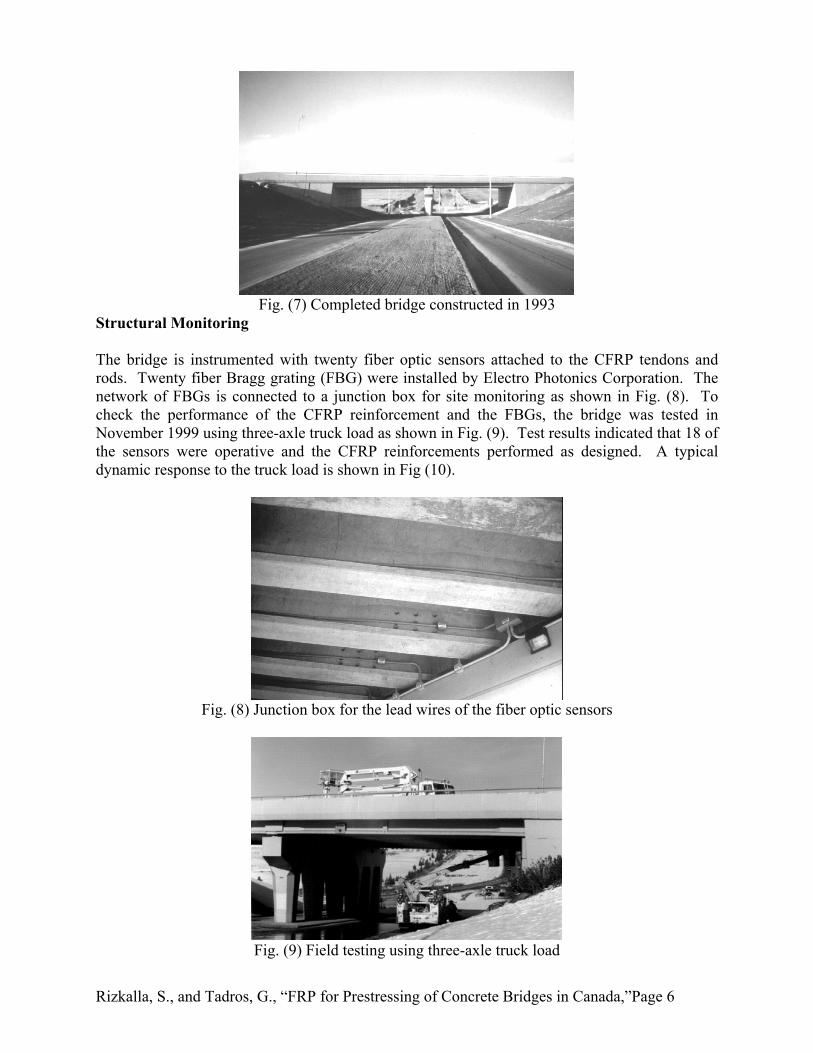
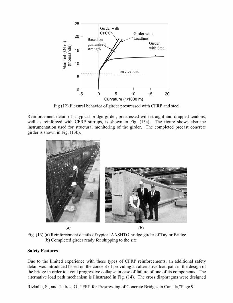
The bridge is instrumented with twenty fiber optic sensors attached to the CFRP tendons and rods. Twenty fiber Bragg grating (FBG) were installed by Electro Photonics Corporation. The network of FBGs is connected to a junction box for site monitoring as shown in Fig. (8). To check the performance of the CFRP reinforcement and the FBGs, the bridge was tested in November 1999 using three-axle truck load as shown in Fig. (9). Test results indicated that 18 of the sensors were operative and the CFRP reinforcements performed as designed. A typical dynamic response to the truck load is shown in Fig (10).
Fig. (8) Junction box for the lead wires of the fiber optic sensors
Fig. (9) Field testing using three-axle truck load

Rizkalla, S., and Tadros, G., “FRP for Prestressing of Concrete Bridges in Canada,”Page 7
Fig. (10) Dynamic field testing of Beddington Trail Bridge
TAYLOR BRIDGE
Taylor Bridge is located in the Parish of Headingley, Manitoba, Canada and was opened to traffic in October 1997. The 541 ft. long bridge (165 m) consists of 40 prestressed concrete AASTO type girders. Four girders of the Taylor Bridge were prestressed by two different types of carbon fiber reinforced polymer (CFRP) material using straight and draped tendons. The girders were also reinforced by CFRP stirrups protruding from the AASHTO type girders to act in composite action with the bridge deck. A portion of the deck slab is reinforced by CFRP reinforcement. Glass fiber reinforced polymer (GFRP) was also used to reinforce the barrier wall. The barrier wall is connected to the deck slab with double-headed stainless steel bars. To obtain continuous information on the behavior of the bridge and the performance of FRP as reinforcement and prestressing tendons, the bridge is monitored to provide data to evaluate the long-term behavior and durability of the FRP materials used. Two different types of CFRP reinforcements were used. Carbon fiber composite cables (CFCC), produced by Tokyo Rope in Japan, were used to pretension two girders, while the other two girders were pretensioned using Leadline bars, produced by Mitsubishi Chemical Corporation in Japan. Double-headed stainless steel tension bars were used for the connection between the barrier wall and the deck slab. Research Work Due to a lack of codes and standards on the use of FRP as reinforcement and prestressing materials for concrete bridges, an extensive experimental program was conducted over five years before construction of the bridge. The program included testing of a large-scale model of a bridge girder totally reinforced and prestressed with carbon FRP [5] and a full scale portion of the bridge deck slab reinforced with CFRP under simulated traffic loads up to failure [6] as shown in Fig. (11a) and (11b) respectively. Straight and draped CFRP reinforcements were also tested under axial tension. Performance of CFRP as shear reinforcement [7] including effect of bend and orientation of the crack on the tensile strength was investigated. Transfer and development lengths of the CFRP reinforcement were also evaluated and a theoretical model was introduced [8]. In addition, a research project [9] was conducted to examine the barrier wall and the deck slab for steel-free bridge decks. The results of all these investigations were used to design the Taylor Bridge.

Rizkalla, S., and Tadros, G., “FRP for Prestressing of Concrete Bridges in Canada,”Page 8
Fig. (11a) Large Scale model of a bridge girder for Taylor Bridge
Fig. (11b) Testing of full-scale portion of the bridge deck
Design Consideration Bridge girders, prestressed and reinforced by CFRP, were designed to behave similar to other girders of the bridge reinforced and prestressed with steel strains under service loading conditions. The prestressing force and the eccentricity of the reinforcement were kept the same for all girders. The initial prestressing level was 60 percent of the guaranteed ultimate tensile strength for CFRP prestressing bars compared to 75 percent for steel strands. The flexural design of girders prestressed by CFRP reinforcement was based on strain compatibility and the material characteristics of CFCC, Leadline and concrete. The predicted flexural behavior of girders prestressed by CFRP was identical to that of girders with steel before cracking as shown in Fig. (12). The design capacity of girders with CFRP, based on the ultimate strength of the reinforcement, was 50 percent higher than that of the girder with steel. It should be noted that the ultimate tensile strength of CFRP reinforcement is higher than the guaranteed value reported by the manufacturer. Based on AASHTO Code 1989, the girders reinforced by CFRP were designed for a stress level in the stirrups of 250 MPa (36.25 ksi) at factored applied load, compared to 200 MPa (29.00 ksi) stress level used for the steel stirrups. The stress in the CFRP stirrups is less than 40 percent of its ultimate capacity.
Rizkalla, S., and Tadros, G., “FRP for Prestressing of Concrete Bridges in Canada,”Page 9
service load
Girder with Leadline
Girder with Steel
Girder with CFCC
Based on guaranteed strength
Mom
ent (
kN-m
) (th
ousa
nds)
Curvature (1/1000 m)-5 0 5 10 15 20
25
20
15
10
5
0
Fig (12) Flexural behavior of girder prestressed with CFRP and steel
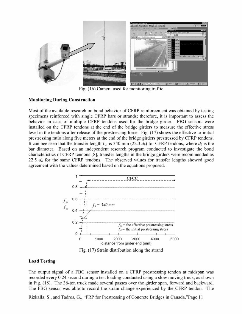
Reinforcement detail of a typical bridge girder, prestressed with straight and drapped tendons, well as reinforced with CFRP stirrups, is shown in Fig. (13a). The figure shows also the instrumentation used for structural monitoring of the girder. The completed precast concrete girder is shown in Fig. (13b).
(a) (b) Fig. (13) (a) Reinforcement details of typical AASHTO bridge girder of Taylor Bridge (b) Completed girder ready for shipping to the site Safety Features Due to the limited experience with these types of CFRP reinforcements, an additional safety detail was introduced based on the concept of providing an alternative load path in the design of the bridge in order to avoid progressive collapse in case of failure of one of its components. The alternative load path mechanism is illustrated in Fig. (14). The cross diaphragms were designed

Rizkalla, S., and Tadros, G., “FRP for Prestressing of Concrete Bridges in Canada,”Page 10
to support the dead load of the bridge in case of the unlikely event of failure of the two girders prestressed by CFRP. In addition, non-prestressed reinforcements were provided in the girders prestressed by CFRP to develop catenary action in case of breakage of the stressed reinforcement.
main girders
cross diaphragms
Arch action
Tie Steel
Steel
Steel
Steel
Steel
Steel
CFRP CFRP
Fig (14) Failure load-path mechanism used in the design of Taylor Bridge
Monitoring System A total of 63 fiber-Bragg grating (FBG) sensors and two multi-Bragg sensors were glued to the reinforcing CFRP bars of the structural members of Taylor Bridge. FBG sensors located at midspan were designed to monitor the maximum strain in the reinforcement due to applied loads, while FBG sensors located at the girder ends were designed to evaluate the transfer length of prestressing tendons. Due to the relatively high initial prestressing strain (~8800 microstrain) and the limited full range of the FBG sensors, most of the sensors were installed after tensioning the prestressing tendons. Some of the FBG sensors were installed before prestressing to measure the initial prestressing strains of the CFRP and steel tendons. The bridge is also being monitored by 26 conventional electrical strain gauges mounted on the reinforcement to verify the readings of the optic sensors. The multiplexing unit and the data logging system were installed in a heated enclosure, located in the cross diaphragm under the bridge deck slab, as shown in Fig. (15). A camera was installed at the bridge site to provide video information synchronized with the optic sensors’ signals as shown in Fig. (16).
Fig (15) Monitoring devices and the computer for Taylor Bridge
Rizkalla, S., and Tadros, G., “FRP for Prestressing of Concrete Bridges in Canada,”Page 11
Fig. (16) Camera used for monitoring traffic
Monitoring During Construction Most of the available research on bond behavior of CFRP reinforcement was obtained by testing specimens reinforced with single CFRP bars or strands; therefore, it is important to assess the behavior in case of multiple CFRP tendons used for the bridge girder. FBG sensors were installed on the CFRP tendons at the end of the bridge girders to measure the effective stress level in the tendons after release of the prestressing force. Fig. (17) shows the effective-to-initial prestressing ratio along five meters at the end of the bridge girders prestressed by CFRP tendons. It can bee seen that the transfer length Lt, is 340 mm (22.3 db) for CFRP tendons, where db is the bar diameter. Based on an independent research program conducted to investigate the bond characteristics of CFRP tendons [8], transfer lengths in the bridge girders were recommended as 22.5 db for the same CFRP tendons. The observed values for transfer lengths showed good agreement with the values determined based on the equations proposed.
0 1000 2000 3000 4000 5000
1 CFCC
Lt = 340 mm
fpe = the effective prestressing stress fpi = the initial prestressing stress
distance from girder end (mm)
pi
pe
ff
0.8
0.6
0.4
0.2
0
Fig. (17) Strain distribution along the strand
Load Testing The output signal of a FBG sensor installed on a CFRP prestressing tendon at midspan was recorded every 0.24 second during a test loading conducted using a slow moving truck, as shown in Fig. (18). The 36-ton truck made several passes over the girder span, forward and backward. The FBG sensor was able to record the strain change experienced by the CFRP tendon. The

Rizkalla, S., and Tadros, G., “FRP for Prestressing of Concrete Bridges in Canada,”Page 12
figure clearly identifies both the truck and the trailer loading as two distinct peaks in the response curve even though the magnitude of the strains are quite small. The direction of travel can also be detected by the relative magnitudes of the peaks since the truck load is larger than the trailer load. Hence, the first event in Fig. (18) represents a backward pass and the subsequent one is a forward pass over the span. Taylor Bridge is shown in Fig. (19).
36-ton Truck
sensor location
-5
0
5
10
15
stra
in (µ
ε)
0 50 100 150 200 time (seconds)
Fig. (18) Field testing of Taylor Bridge
Fig. (19) Taylor Bridge, 1997
ACKNOWLEDGEMENT
The authors wish to acknowledge the support of the Network of Centres of Excellence on Intelligent Sensing for Innovative Structures (ISIS Canada) and Manitoba Highways and Transportation Department of the Province of Manitoba. The writers gratefully acknowledge support provided by E-TEK Electrophotonics Solutions, Toronto, Ontario, Canada, for providing the materials used in the Taylor Bridge. Special thanks are extended to Walter Saltzberg, Chris Wade, Amr Abdelrahman, Amir Fam and Emile Shehata for their assistance during the design and construction of the bridge.
Rizkalla, S., and Tadros, G., “FRP for Prestressing of Concrete Bridges in Canada,”Page 13
REFERENCES
1. Tokyo Rope Mfg Co., Ltd. 1993. Technical Data on CFCC, Japan, 100 pp. 2. Mitsubishi Kasei Corporation. 1992. Leadline Carbon Fiber Rods, Technical Data, Japan, 40
pp. 3. Rizkalla, S. and G. Tadros. 1994. “First Smart Bridge in Canada”, ACI Concrete
International, Vol. 16, No. 6, pp. 42-44. 4. Abdelrahman, AA, G. Tadros and S. Rizkalla. 1995. “Test Model for the First Canadian
Smart Highway Bridge”, ACI Structural Journal, July/August 1995, Vol. 92, No.4, pp. 451-458.
5. Fam, A., S. Rizkalla, and G. Tadros. 1997. “Behavior of CFRP for Prestressing and Shear Reinforcements of Concrete Highway Bridges”, ACI Structural Journal, January/February 1997, Vol. 94, No.1, pp. 77-86.
6. Charleson, K., A. Abdelrahman, S. Rizkalla, and W. Saltzberg. 1997. “Behavior of a Model Concrete Bridge Deck Reinforced by CFRP”, Proceedings of FRPRCS-3 International Conference, Sapporo, Japan, Vol. II: 575-582.
7. Shehata, E., R. Morphy, and S. Rizkalla. 1999. “Fiber Reinforced Polymer Reinforcement for Concrete Structures”, ACI Special Publication SP-188, Editors: C. Dolan, S. Rizkalla, and A. Nanni: 157-167.
8. Mahmoud, Z., S. Rizkalla, and E.-E. Zaghloul. 1999. “Transfer and Development Lengths of Carbon Fiber Reinforced Polymers Prestressing Reinforcement”, ACI Structural Journal, July/August 1999, Vol. 96, No.4, pp. 594-602.
9. Maheu, J., and B. Bakht. 1994. “A New Connection Between Concrete Barrier Walls and Bridge Decks”, Proceedings of the 22nd CSCE Annual Conference, Winnipeg, Manitoba, Canada, Vol. II: 224-229.