from soils to design - colorado professionals in onsite ... soils to design ... developing design...
TRANSCRIPT
Using Soils Information &
Regulation 43 to Design
OWTSBy Jennifer Migliorato
Eastbound Westbound, Inc.
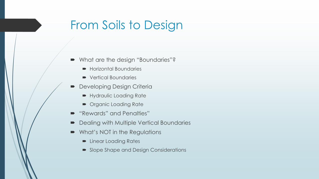
From Soils to Design
What are the design “Boundaries”?
Horizontal Boundaries
Vertical Boundaries
Developing Design Criteria
Hydraulic Loading Rate
Organic Loading Rate
“Rewards” and Penalties”
Dealing with Multiple Vertical Boundaries
What’s NOT in the Regulations
Linear Loading Rates
Slope Shape and Design Considerations
BoundariesWhat are the site-specific conditions?
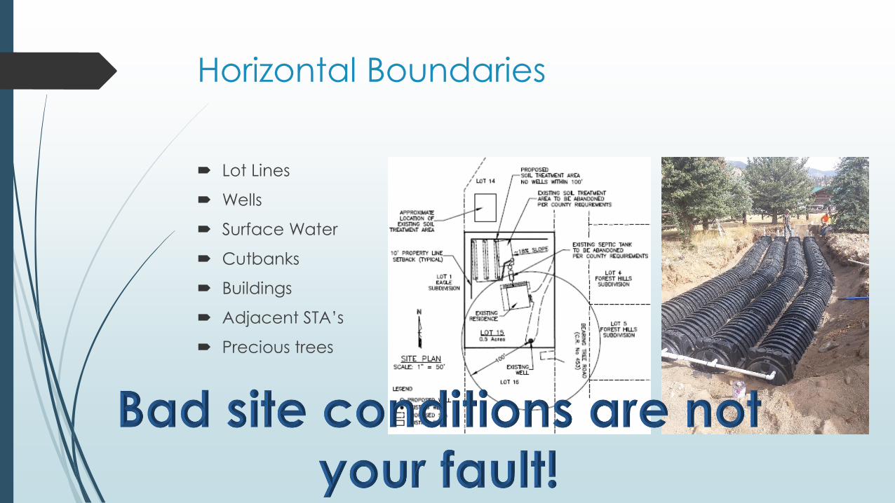
Horizontal Boundaries
Lot Lines
Wells
Surface Water
Cutbanks
Buildings
Adjacent STA’s
Precious trees
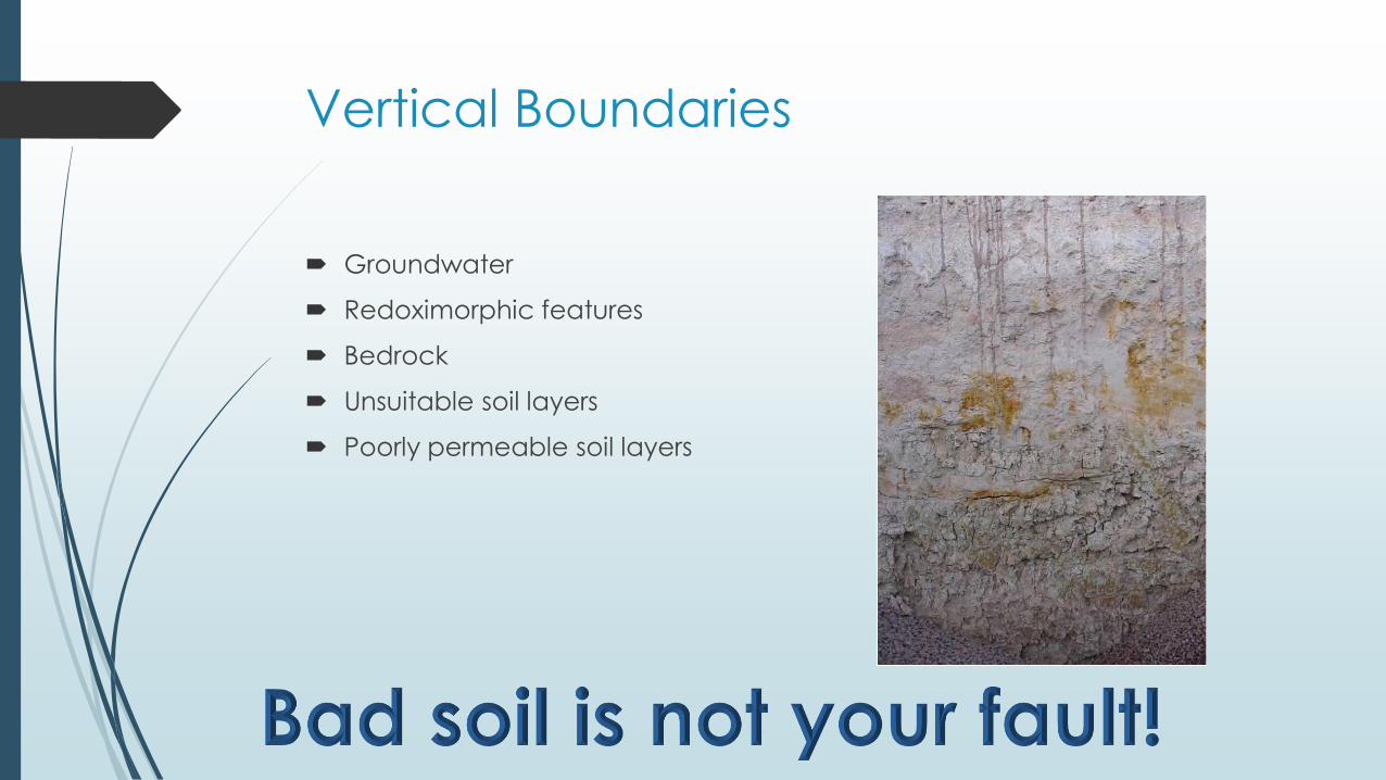
Vertical Boundaries
Groundwater
Redoximorphic features
Bedrock
Unsuitable soil layers
Poorly permeable soil layers
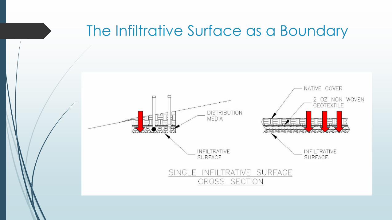
The Infiltrative Surface as a Boundary
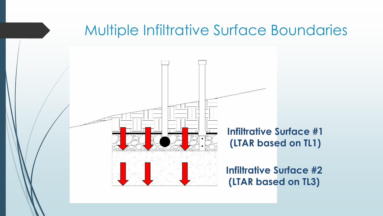
Multiple Infiltrative Surface Boundaries
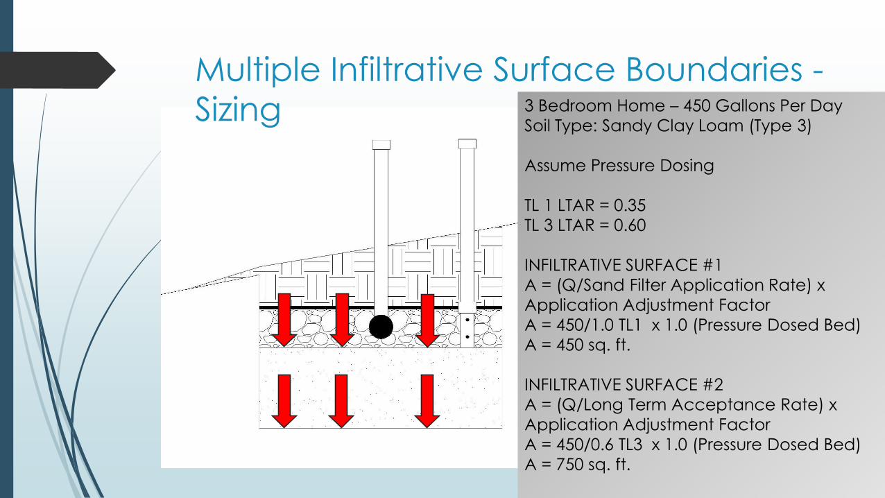
Multiple Infiltrative Surface Boundaries -
Sizing 3 Bedroom Home – 450 Gallons Per Day
Soil Type: Sandy Clay Loam (Type 3)
Assume Pressure Dosing
TL 1 LTAR = 0.35
TL 3 LTAR = 0.60
INFILTRATIVE SURFACE #1
A = (Q/Sand Filter Application Rate) x
Application Adjustment Factor
A = 450/1.0 TL1 x 1.0 (Pressure Dosed Bed)
A = 450 sq. ft.
INFILTRATIVE SURFACE #2
A = (Q/Long Term Acceptance Rate) x
Application Adjustment Factor
A = 450/0.6 TL3 x 1.0 (Pressure Dosed Bed)
A = 750 sq. ft.

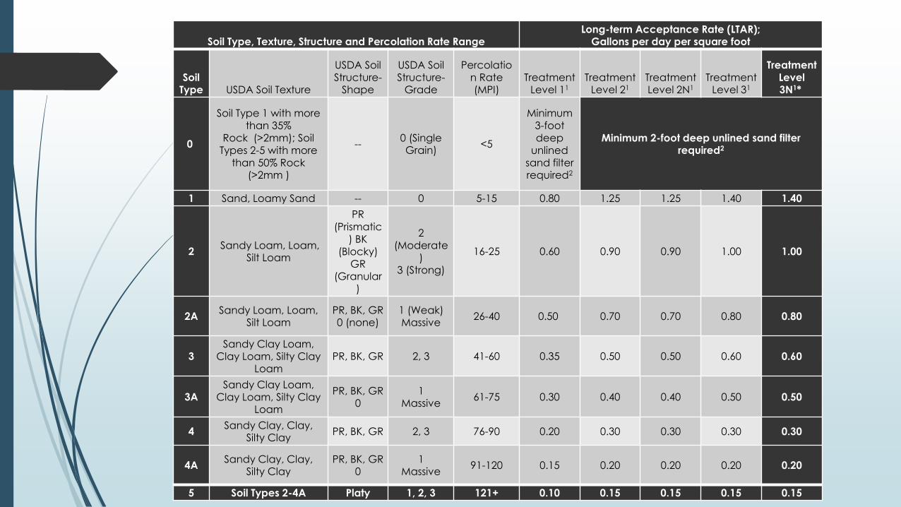
Soil Type, Texture, Structure and Percolation Rate RangeLong-term Acceptance Rate (LTAR);
Gallons per day per square foot
Soil Type USDA Soil Texture
USDA Soil Structure-
Shape
USDA Soil Structure-
Grade
Percolation Rate (MPI)
Treatment Level 11
Treatment Level 21
Treatment Level 2N1
Treatment Level 31
Treatment Level 3N1*
0
Soil Type 1 with more than 35%
Rock (>2mm); Soil Types 2-5 with more
than 50% Rock (>2mm )
--0 (Single Grain)
<5
Minimum 3-foot deep
unlined
sand filter required2
Minimum 2-foot deep unlined sand filter required2
1 Sand, Loamy Sand -- 0 5-15 0.80 1.25 1.25 1.40 1.40
2Sandy Loam, Loam,
Silt Loam
PR (Prismatic
) BK (Blocky)
GR (Granular
)
2 (Moderate
)3 (Strong)
16-25 0.60 0.90 0.90 1.00 1.00
2ASandy Loam, Loam,
Silt LoamPR, BK, GR0 (none)
1 (Weak)Massive
26-40 0.50 0.70 0.70 0.80 0.80
3Sandy Clay Loam,
Clay Loam, Silty Clay Loam
PR, BK, GR 2, 3 41-60 0.35 0.50 0.50 0.60 0.60
3ASandy Clay Loam,
Clay Loam, Silty Clay Loam
PR, BK, GR0
1Massive
61-75 0.30 0.40 0.40 0.50 0.50
4Sandy Clay, Clay,
Silty ClayPR, BK, GR 2, 3 76-90 0.20 0.30 0.30 0.30 0.30
4ASandy Clay, Clay,
Silty ClayPR, BK, GR
01
Massive91-120 0.15 0.20 0.20 0.20 0.20
5 Soil Types 2-4A Platy 1, 2, 3 121+ 0.10 0.15 0.15 0.15 0.15
Design CriteriaHydraulic and Organic Loading to the Infiltrative Surface
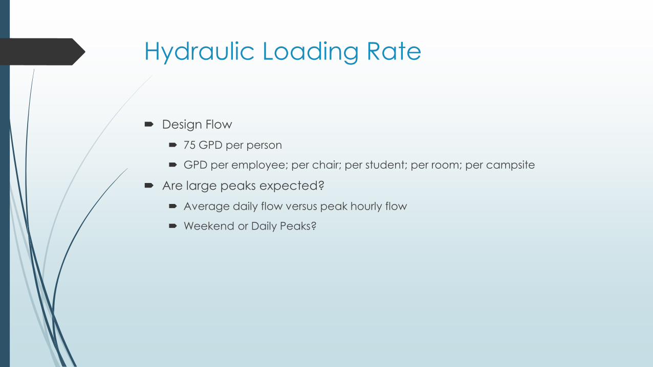
Hydraulic Loading Rate
Design Flow
75 GPD per person
GPD per employee; per chair; per student; per room; per campsite
Are large peaks expected?
Average daily flow versus peak hourly flow
Weekend or Daily Peaks?
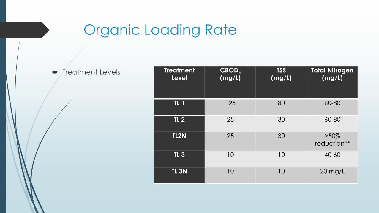
Organic Loading Rate
Treatment Levels Treatment Level
CBOD5
(mg/L)TSS
(mg/L)Total Nitrogen
(mg/L)
TL 1 125 80 60-80
TL 2 25 30 60-80
TL2N 25 30 >50% reduction**
TL 3 10 10 40-60
TL 3N 10 10 20 mg/L
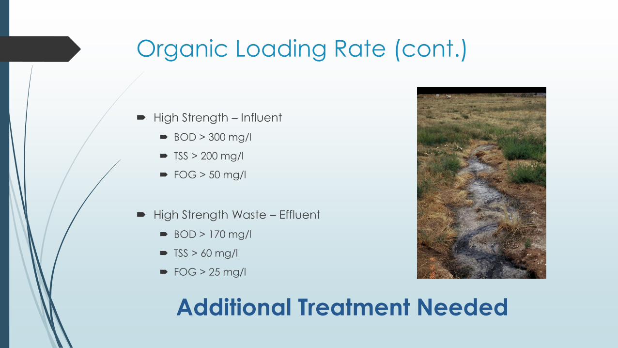
Organic Loading Rate (cont.)
High Strength – Influent
BOD > 300 mg/l
TSS > 200 mg/l
FOG > 50 mg/l
High Strength Waste – Effluent
BOD > 170 mg/l
TSS > 60 mg/l
FOG > 25 mg/l
Additional Treatment Needed
Soil Type, Texture, Structure and Percolation Rate RangeLong-term Acceptance Rate (LTAR);
Gallons per day per square foot
Soil Type USDA Soil Texture
USDA Soil Structure-
Shape
USDA Soil Structure-
Grade
Percolation Rate (MPI)
Treatment Level 11
Treatment Level 21
Treatment Level 2N1
Treatment Level 31
Treatment Level 3N1*
0
Soil Type 1 with more than 35%
Rock (>2mm); Soil Types 2-5 with more
than 50% Rock (>2mm )
--0 (Single Grain)
<5
Minimum 3-foot deep
unlined
sand filter required2
Minimum 2-foot deep unlined sand filter required2
1 Sand, Loamy Sand -- 0 5-15 0.80 1.25 1.25 1.40 1.40
2Sandy Loam, Loam,
Silt Loam
PR (Prismatic
) BK (Blocky)
GR (Granular
)
2 (Moderate
)3 (Strong)
16-25 0.60 0.90 0.90 1.00 1.00
2ASandy Loam, Loam,
Silt LoamPR, BK, GR0 (none)
1 (Weak)Massive
26-40 0.50 0.70 0.70 0.80 0.80
3Sandy Clay Loam,
Clay Loam, Silty Clay Loam
PR, BK, GR 2, 3 41-60 0.35 0.50 0.50 0.60 0.60
3ASandy Clay Loam,
Clay Loam, Silty Clay Loam
PR, BK, GR0
1Massive
61-75 0.30 0.40 0.40 0.50 0.50
4Sandy Clay, Clay,
Silty ClayPR, BK, GR 2, 3 76-90 0.20 0.30 0.30 0.30 0.30
4ASandy Clay, Clay,
Silty ClayPR, BK, GR
01
Massive91-120 0.15 0.20 0.20 0.20 0.20
5 Soil Types 2-4A Platy 1, 2, 3 121+ 0.10 0.15 0.15 0.15 0.15
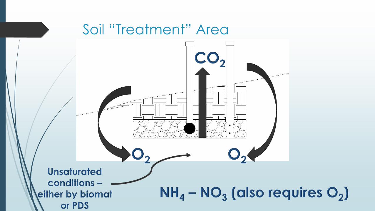
Soil “Treatment” Area
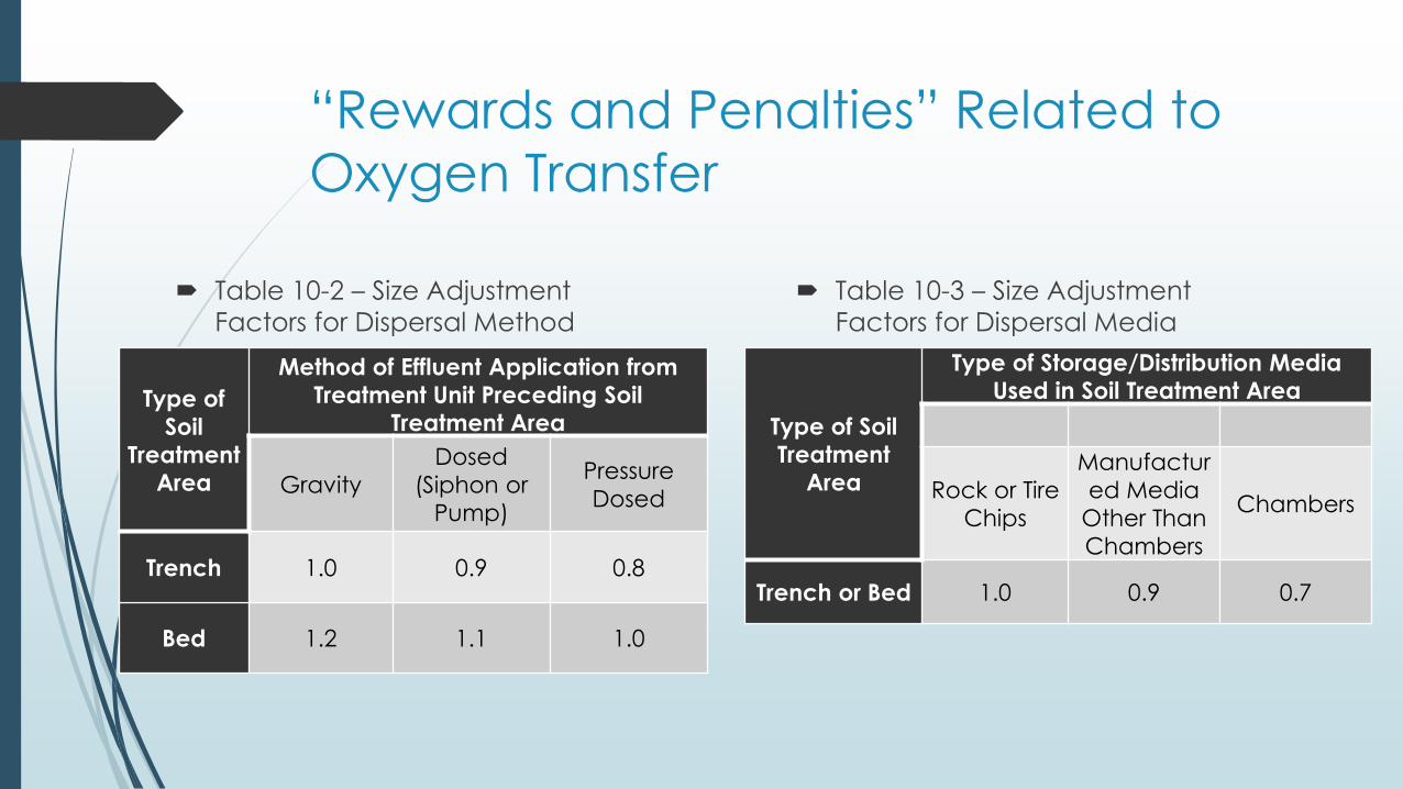
“Rewards and Penalties” Related to
Oxygen Transfer
Table 10-2 – Size Adjustment
Factors for Dispersal Method
Table 10-3 – Size Adjustment
Factors for Dispersal Media
Type of
Soil
Treatment Area
Method of Effluent Application from
Treatment Unit Preceding Soil Treatment Area
Gravity
Dosed
(Siphon or
Pump)
Pressure
Dosed
Trench 1.0 0.9 0.8
Bed 1.2 1.1 1.0
Type of Soil
Treatment Area
Type of Storage/Distribution Media Used in Soil Treatment Area
Rock or Tire
Chips
Manufactur
ed Media
Other Than
Chambers
Chambers
Trench or Bed 1.0 0.9 0.7
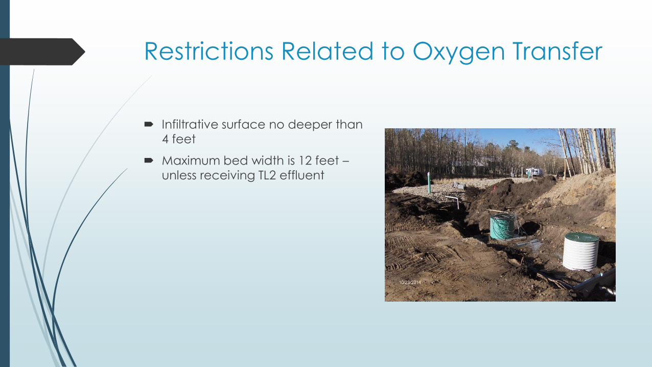
Restrictions Related to Oxygen Transfer
Infiltrative surface no deeper than
4 feet
Maximum bed width is 12 feet –
unless receiving TL2 effluent

What’s NOT in the Regulations?
Linear Loading Rate (Contour Loading Rate)
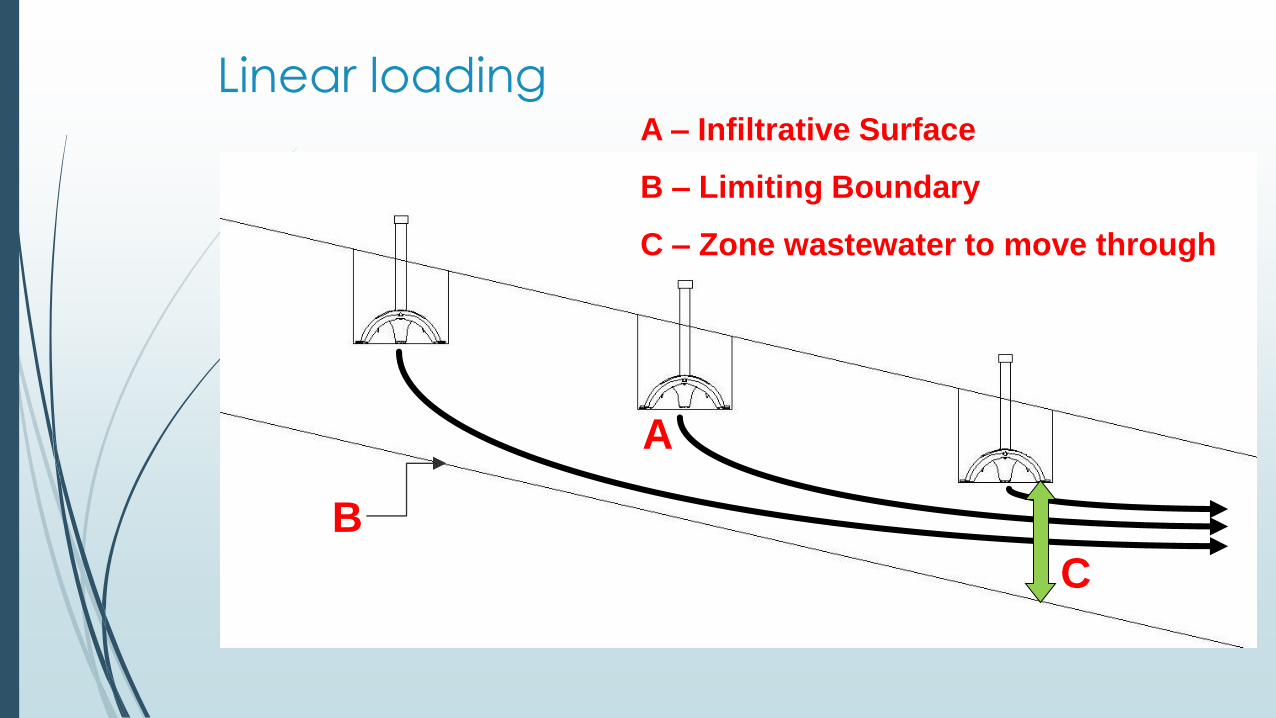
Linear loading
B
A
C
A – Infiltrative Surface
B – Limiting Boundary
C – Zone wastewater to move through
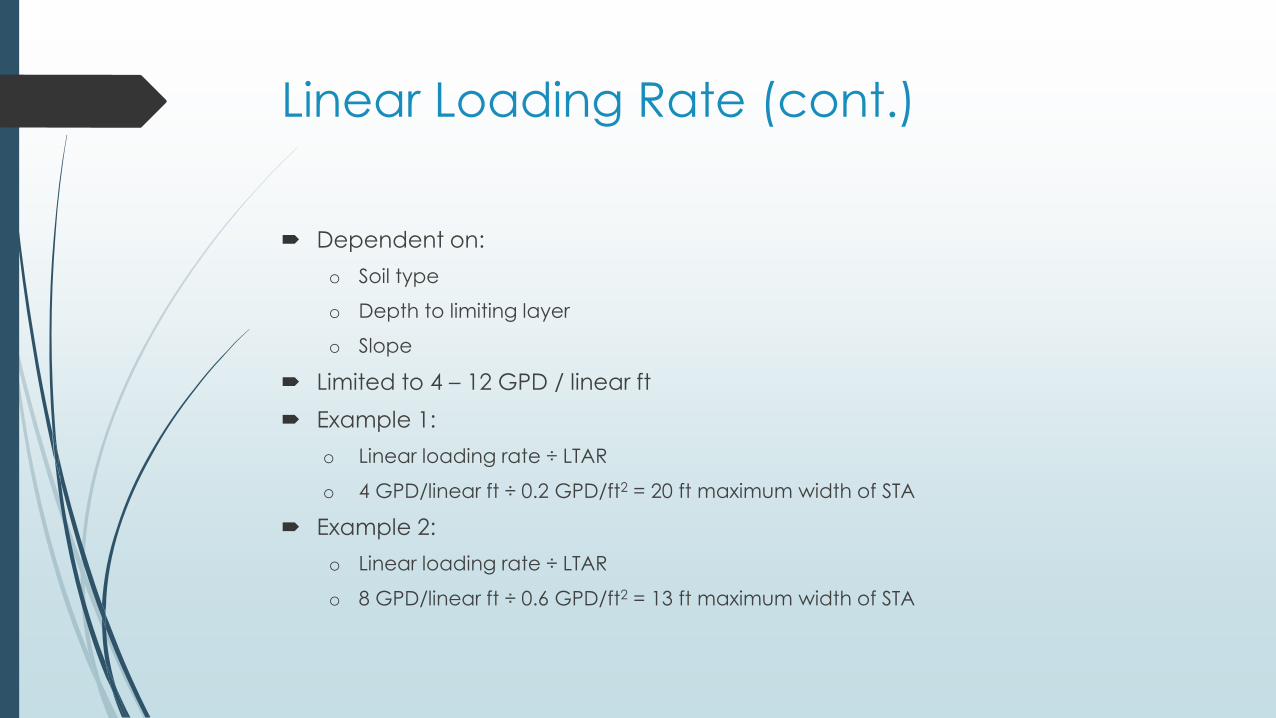
Linear Loading Rate (cont.)
Dependent on:
o Soil type
o Depth to limiting layer
o Slope
Limited to 4 – 12 GPD / linear ft
Example 1:
o Linear loading rate ÷ LTAR
o 4 GPD/linear ft ÷ 0.2 GPD/ft2 = 20 ft maximum width of STA
Example 2:
o Linear loading rate ÷ LTAR
o 8 GPD/linear ft ÷ 0.6 GPD/ft2 = 13 ft maximum width of STA
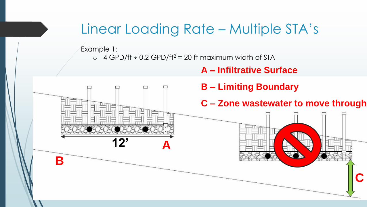
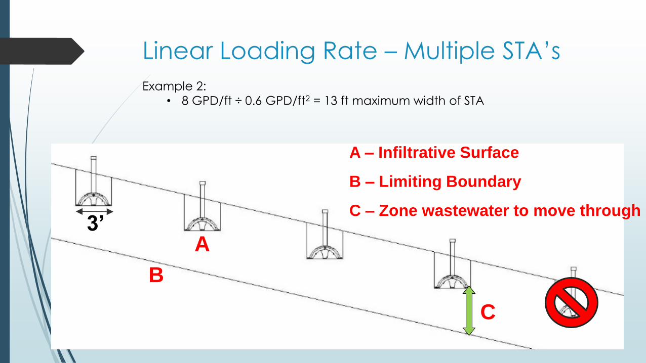
Linear Loading Rate – Multiple STA’s
A – Infiltrative Surface
B – Limiting Boundary
C – Zone wastewater to move through
Example 1:
o 4 GPD/ft ÷ 0.2 GPD/ft2 = 20 ft maximum width of STA
C
A
B
12’
Linear Loading Rate – Multiple STA’s
A – Infiltrative Surface
B – Limiting Boundary
C – Zone wastewater to move through
Example 2:
• 8 GPD/ft ÷ 0.6 GPD/ft2 = 13 ft maximum width of STA
C
A
B
3’
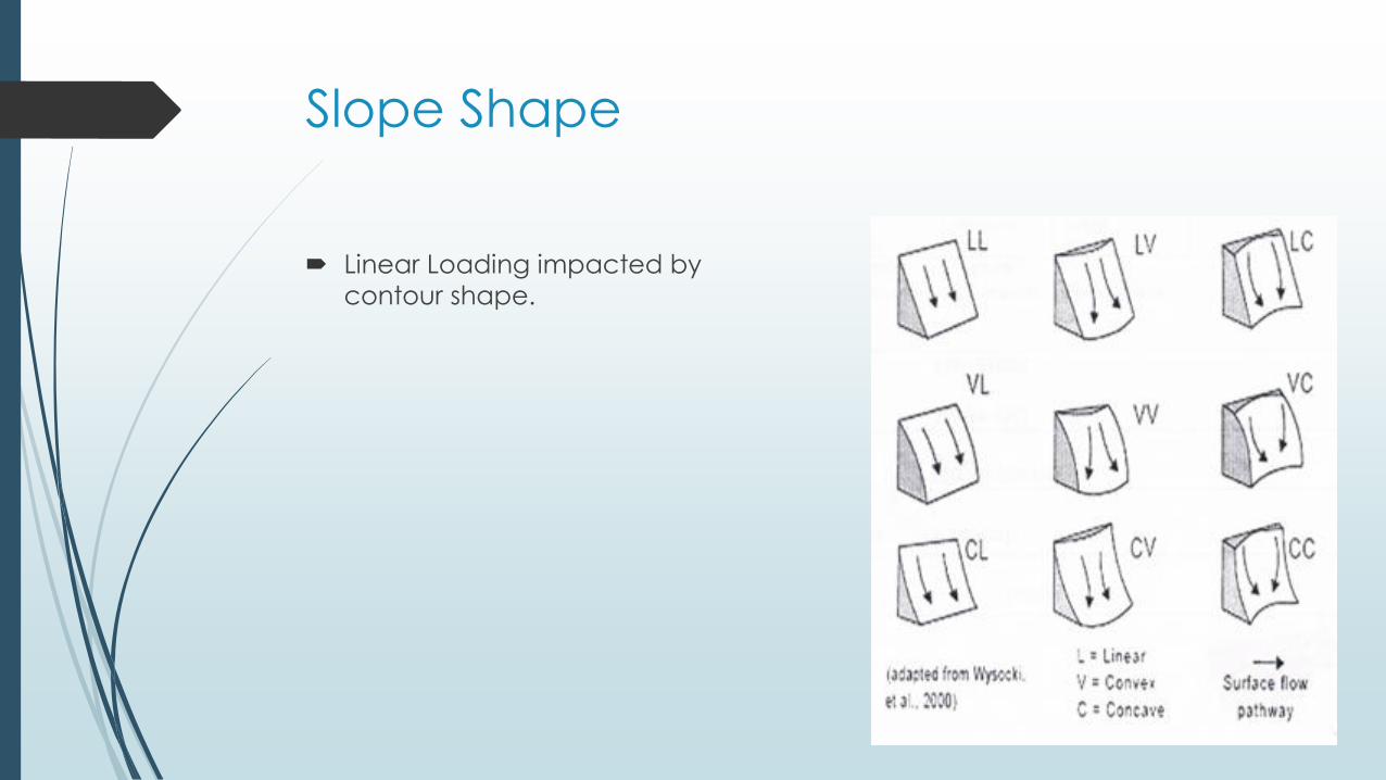
Slope Shape
Linear Loading impacted by
contour shape.