friction welding of ductile iron with stainless steel
DESCRIPTION
FRICTION WELDING OF DUCTILE IRON WITH STAINLESS STEELTRANSCRIPT
F
Ra
b
a
ARRAA
KFDSM
1
cfmimAbtiefcatiao
we
f
(
0h
Journal of Materials Processing Technology 213 (2013) 453– 462
Contents lists available at SciVerse ScienceDirect
Journal of Materials Processing Technology
jou rna l h om epa g e: www.elsev ier .com/ locate / jmatprotec
riction welding of ductile iron with stainless steel
adosław Winiczenkoa,∗, Mieczysław Kaczorowskib,1
Warsaw University of Life Sciences, Department of Production Engineering, Nowoursynowska 166, 02-787 Warsaw, PolandWarsaw University of Technology, Institute of Mechanics and Design, Narbutta 85, 02-524 Warsaw, Poland
r t i c l e i n f o
rticle history:eceived 1 April 2012eceived in revised form 9 October 2012ccepted 17 October 2012vailable online 26 October 2012
a b s t r a c t
The study of mechanical properties and microstructure of friction welded coupe of ductile iron with stain-less steel are presented. Scanning electron microscopy (SEM) was used for investigation of the fracturemorphology and phase transformations taking place during friction welding process. It was concludedthat in case of bainitic ductile iron (BDI) the fracture precedes mainly trough the cleavage planes. More-
eywords:riction weldinguctile irontainless steelicrostructure
over, the distribution of selected elements on both side of the joining interface was studied using EDSline and maps spectrometry. The EDS spectrometry showed some enrichment of ductile iron with Cr andNi atoms close to the joint. The depth of Cr atoms penetration reached 50 �m. The heat generated locallyby friction increased the temperature in the area close to the interface even over the melting point ofductile iron. This was confirmed by metallography which revealed the carbide eutectic enriched with Crin ductile iron.
. Introduction
Friction welding is a solid-state joining process which producesoalescence in materials, using the heat generated between sur-aces through the combination of a mechanically induced rubbing
otion and the applied load. The resulting joints are of forged qual-ty. Under normal conditions, the faying surfaces do not melt. Filler
etal, flux and shielding gas are not required with this process.s a rule, all metallic engineering materials that are forgeable cane friction welded, including automotive valve alloys, tool steel,antalum, alloy steels and maraging steel. In addition, many cast-ngs, powder metals and metal matrix composites are weldable. Forxample, engine pistons, used mainly for truck applications, can beriction welded. In general, there are two different types of materialombinations–the first being a combination of steel and aluminum,nd the second consisting of ductile cast iron with mild steel. Fric-ion welding is applied for welding low ductility materials becauset causes crystal refinement, the pattern of the heat flow is simplend high compressive residual stresses are involved on the surfacef these joints (Lancaster, 1987).
According to the American Welding Society (AWS), frictionelding is the ideal method for joining metals that are not nec-
ssarily similar. Many authors have recently conducted extensive
∗ Corresponding author. Tel.: +48 225 934 624;ax: +48 225 225 934 618/225 934 611.
E-mail addresses: radoslaw [email protected], [email protected]. Winiczenko), [email protected] (M. Kaczorowski).
1 Tel.: +48 228 494 280; fax: +48 228 483 379.
924-0136/$ – see front matter © 2012 Elsevier B.V. All rights reserved.ttp://dx.doi.org/10.1016/j.jmatprotec.2012.10.008
© 2012 Elsevier B.V. All rights reserved.
investigation into the friction welding of dissimilar materials.The main reasons for dissimilar joining are due to the combi-nation of good mechanical properties of one material and thelow specific weight, good corrosion resistance, and good electri-cal properties of a second material. During the friction weldingof dissimilar materials, significant cost saving is possible becauseengineers can design bimetallic parts that use expensive mate-rials only where needed. Expensive forgings and castings can bereplaced with less expensive forgings to bar steel, tubes, plates andsuchlike.
Sahin Ahmet et al. (1998) analyzed the friction welding processin relation to the welding of copper to steel bars and subsequentlyobtained good quality welding joints. Satyanarayana et al. (2005)successfully achieved the joining of austenitic–ferritic stainlesssteels using the friction welding process. Sahin (2005) joined high-speed steel (HSS-S 6-5-2) and medium carbon steel (AISI 1040).The strengths of the joints were determined by tension, fatigueand notch-impact tests, and his results were compared with thetensile strength of the base materials. The same author also con-ducted studies on the friction welding of stainless steel and coppermaterials (Sahin, 2009). Meshram et al. (2007) conducted an inves-tigation of dissimilar metal joining combinations: Fe–Ti, Cu–Ti,Fe–Cu, Fe–Ni and Cu–Ni. He observed the influence of interac-tion time on microstructure and tensile properties of the frictionwelding of five dissimilar metal combinations. Dey et al. (2009)carried out research concerning the friction welding of titanium
to stainless steel. His studies confirmed the presence of secondaryphases in the inter-mix zone near the interface. Seli et al. (2010)conducted both a mechanical evaluation and thermal modelingof the friction welding of mild steel and aluminum. They used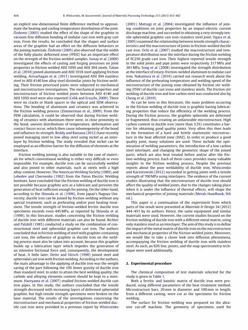
4 terials
amÖviatooipewsiamAwttFitcajlei
aiaaLIngavsms(oasccibaoststcmisgbmt
54 R. Winiczenko, M. Kaczorowski / Journal of Ma
n explicit one-dimensional finite difference method to approxi-ate the heating and cooling temperature distribution of the joint.zdemir (2003) studied the effect of the shape of the graphite inacuum-free diffusion bonding of nodular cast iron with gray castron. From the results, he concluded that the shapes and surfacereas of the graphite had an effect on the diffusion behaviors orhe joining materials. Özdemir (2005) also observed that the widthf the fully plastic deformed zone (FPDZ) has an important effectn the strength of the friction-welded samples. Sunay et al. (2009)nvestigated the effects of casting and forging processes on jointroperties in friction welded AISI 1050 and AISI 304 steels. Tabant al. (2010) joined aluminum and AISI 1018 steel applying frictionelding. Arivazhagan et al. (2011) investigated AISI 304 stainless
teel to AISI 4140 low alloy steel dissimilar joints by friction weld-ng. Their friction processed joints were subjected to mechanicalnd microstructure investigations. The mechanical properties andicrostructure of friction welded joints between AISI 4140 andISI 1050 steel were also reported (Celik and Ersozlu, 2009). Thereere no cracks or blank spaces in the optical and SEM observa-
ions. The bonding of aluminum and ceramics was achieved inhe friction welding process (Zimmerman et al., 2009). From theEM calculation, it could be observed that during friction weld-ng of ceramics with aluminum there were, in close proximity tohe bond, uneven distributions of temperature, deformation andontact forces occur, which then cause inhomogeneity of the bondnd influence its strength. Reddy and Ramana (2012) have recentlyoined maraging steel to low alloy steel using nickel as an inter-ayer by friction welding. The study revealed that nickel can bemployed as an effective barrier for the diffusion of elements at thenterface.
Friction welding joining is also suitable in the case of materi-ls for which conventional welding is either very difficult or evenmpossible. For example, ductile iron can be successfully weldednd also joined to other materials, such as steels with a highlloy-content. However, The American Welding Society (1989), andebedev and Chernenko (1992) from the Paton Electric Weldingnstitute, have concluded that the friction welding of ductile iron isot possible because graphite acts as a lubricant and prevents theeneration of heat sufficient enough for joining. On the other hand,ccording to the Shinoda et al. (1996), from Japan’s Nagoya Uni-ersity, ductile iron can be joined by friction welding without anypecial treatment, such as preheating and/or post heating treat-ent. The tensile strength of friction-welded ferritic ductile iron
pecimens exceeds even 445 MPa, as reported by Shinoda et al.1999). In this literature, studies concerning the friction weldingf ductile iron with different materials can also be found. Richternd Palzkill (1985) conducted a study on the combination of con-tructional steel and spheroidal graphite cast iron. The authorsoncluded that in friction welding of steel with graphite-containingast iron, the influence of graphite in ductile iron on the weld-ng process must also be taken into account, because this graphiteuilds up a lubrication layer which impedes the generation ofn intensive frictional force and, consequently, the developmentf heat. A little later, Dette and Hirsch (1990) joined steel andpheroidal cast iron with friction welding. According to the authors,he main advantage to the applying of ductile iron was the weightaving of the part following the 10% lower gravity of ductile ironhan standard steel. In order to attain the best welding quality, thearbide and alloying elements content should be kept to a mini-um. Hareyama et al. (2007) studied friction-welded ductile cast
ron pipes. In this study, the authors concluded that the tensiletrength decreased with increasing layers of deformed spheroidal
raphite, but high tensile strength specimens were broken on thease material. The results of the investigations concerning theicrostructure and mechanical properties of friction-welded duc-ile cast iron were provided in a previous report by Winiczenko
Processing Technology 213 (2013) 453– 462
(2001). Matsugi et al. (2004) investigated the influence of join-ing conditions on joint properties by an impact-electric currentdischarge machine, and succeeded in obtaining a very strongly ten-sile spheroidal graphite cast iron–stainless steel joint. Ogara et al.(2005) examined the relationship between tensile strength charac-teristics and the macrostructure of joints in friction-welded ductilecast iron. Ochi et al. (2007) studied the macrostructure and tem-perature distribution near the interface during the friction weldingof FC250 grade cast iron. Their highest reported tensile strengthin the solid joints and pipe joints were respectively 317 MPa and381 MPa. Song et al. (2008) investigated the strength distributionat the interface of rotary-friction-welded aluminum to nodular castiron. Nakamura et al. (2010) carried out research work about theinfluence of the preheating temperature and welding speed of themicrostructure of the joining zone obtained by friction stir weld-ing (FSW) of ductile cast irons and stainless steels. The friction stirwelding of ductile iron and low carbon steel was conducted also byCheng et al. (2010).
As can be seen in this literature, the main problem occurringin the friction welding of ductile iron is graphite having lubricat-ing properties that reduce the efficiency of the welding process.During the friction process, the graphite spheroids are deformedor fragmented, thus creating an unfavorable microstructure. Highcarbon content in ductile iron (more than 3.5%) constitutes a bar-rier for obtaining good quality joints. Very often this then leadsto the formation of a hard and brittle martensitic microstruc-ture in the heat affected zone (HAZ). In order to produce a goodquality joint, many solutions are used. These include the opti-mization of welding parameters, the introduction of a low carbonsteel interlayer, and changing the geometric shape of the joinedparts; which are also heat treated before and/or after the fric-tion welding process. Each of these cases provides many valuableinsights to the friction welding process. Despite the previousreports about the poor weldability of ductile iron, Winiczenkoand Kaczorowski (2012) succeeded in getting joints with a tensilestrength of 700 MPa using interlayers. The evidence of the currentstudies illustrating that the microstructure of ductile iron shouldaffect the quality of welded joints, due to the changes taking placewhen it is under the influence of thermal effects, will shape themechanical properties of joining materials (Metals Handbook, 9thed.).
This paper is a continuation of the experiment from whichparts of the result were presented at Materials & Design 34 (2012)444–451 by its authors. Hence, the same equipment and similarmaterials were used. However, the current studies focused on thefriction welding of ductile iron with a different metal matrix, usingonly stainless steel as an interlayer. The aim of this study is to definethe impact of the metal matrix of ductile iron on the microstructureand mechanical properties of the friction welded joints. Moreover,we would like to take a closer look into diffusion phenomena,accompanying the friction welding of ductile iron with stainlesssteel. As such, an EDS line, points, and the map spectrometry tech-nique were used additionally.
2. Experimental procedure
The chemical composition of test materials selected for thestudy is given in Table 1.
Both a ferritic and bainitic matrix of ductile iron were pro-duced, using different parameters of the heat treatment method.Microstructure bars, 20 mm in diameter and 100 mm in length,
from a different casting, were cut as the specimens for frictionwelding.The surface for friction welding was prepared on the abra-sive cut-off machine. The geometry of specimens used for
R. Winiczenko, M. Kaczorowski / Journal of Materials Processing Technology 213 (2013) 453– 462 455
Table 1The chemical composition of materials (wt.%).
Material Alloying elements (wt.%)
C Si Mn P S Cr Ni Mg Fe
fF
uiamwewmhsfweJmedltEami
Fd
60-45-12 3.50–3.90 2.25–3.0 0.30–0.45 0.012–0.05
AISI 321 0.08 max 0.8 max 2.0 max 0.045 max
riction welding and details of the experiment were presented inig. 1.
The friction welding of ductile iron specimens was conductedsing AISI 321 stainless steel as an interlayer. The process of join-
ng was carried out on the continuous drive friction machine of ZT-14 type. Friction and forged pressures used in the experi-ent were in the range of 20–45 kN. The spindle rotating speedas kept at a constant speed of 2360 rpm. Because of the pres-
nce of graphite, a relatively large friction time (FT) of 120–270 sas applied. The tensile strength (TS) of the joints was deter-ined using a conventional tensile test machine. Furthermore, the
ardness across the interface was measured on a metallographicpecimen. The Vickers tester, using the 0.05 N load, was appliedor the hardness measurements. The microstructure of the jointsas examined, using both light metallography as well as scanning
lectron microscopy (SEM). The latter one was carried out with aeol JSM-5400 scanning electron microscope. The surfaces of speci-
ens were observed in the BEI COMPO mode, using back-scatteredlectrons (BSE). The studies were conducted on the interface usingifferent variants including: EDS–SEM map analysis and the EDS-
inear analysis. In the first case, the information was collected fromhe area whose size depended on the magnification. In this case, theDS-analysis was performed for the distribution of such elements
s C, Cr, Ni and Fe. The aim of the EDS-linear analysis was to deter-ine the changes in the distribution of: C, Cr, Fe and Ni across thenterface.
ig. 1. Shape and size of specimens (unit: mm) before friction welding: (a) friction weldiuctile iron to ductile iron by the interlayer as a second welding cycle.
0.004–0.022 0.03–0.2 0.02–0.15 0.041–0.105 Rest0.030 max 17–19 9–12 – Rest
3. Results and discussion
3.1. Tensile test
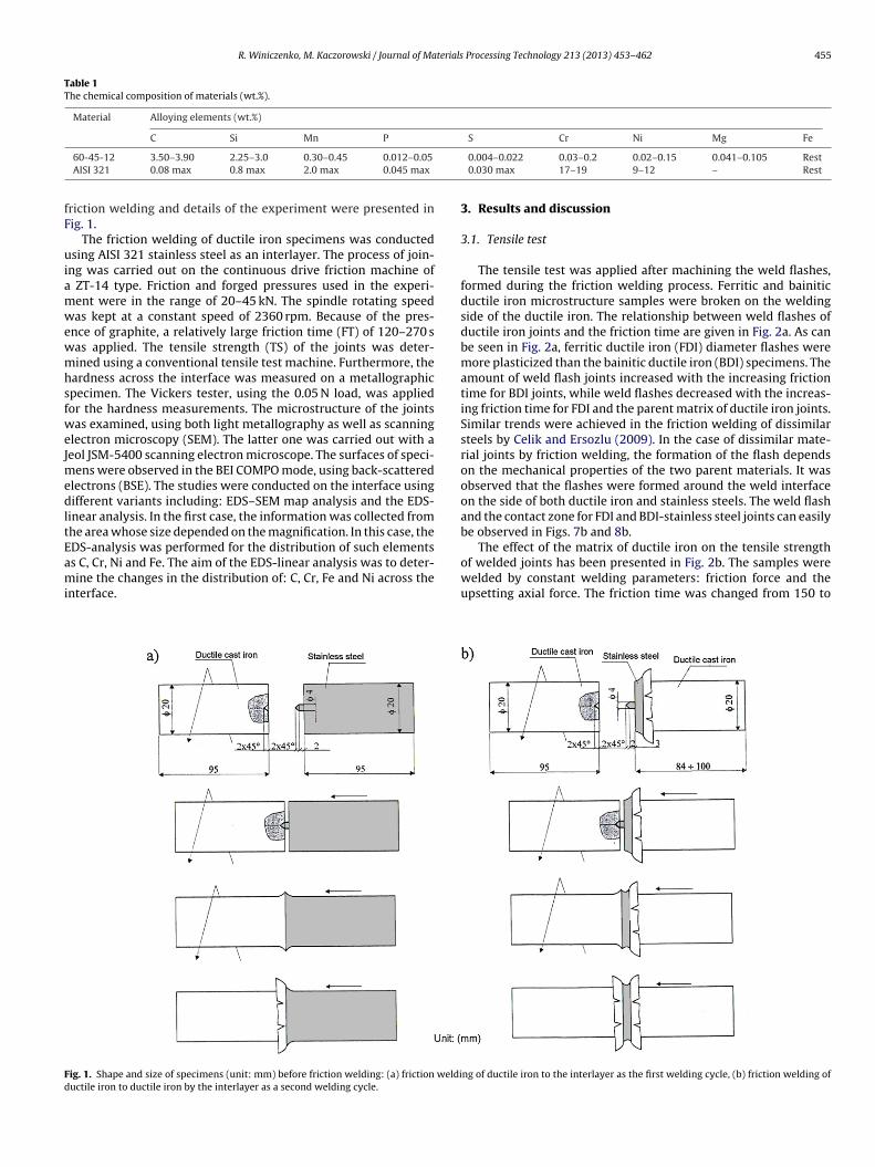
The tensile test was applied after machining the weld flashes,formed during the friction welding process. Ferritic and bainiticductile iron microstructure samples were broken on the weldingside of the ductile iron. The relationship between weld flashes ofductile iron joints and the friction time are given in Fig. 2a. As canbe seen in Fig. 2a, ferritic ductile iron (FDI) diameter flashes weremore plasticized than the bainitic ductile iron (BDI) specimens. Theamount of weld flash joints increased with the increasing frictiontime for BDI joints, while weld flashes decreased with the increas-ing friction time for FDI and the parent matrix of ductile iron joints.Similar trends were achieved in the friction welding of dissimilarsteels by Celik and Ersozlu (2009). In the case of dissimilar mate-rial joints by friction welding, the formation of the flash dependson the mechanical properties of the two parent materials. It wasobserved that the flashes were formed around the weld interfaceon the side of both ductile iron and stainless steels. The weld flashand the contact zone for FDI and BDI-stainless steel joints can easilybe observed in Figs. 7b and 8b.
The effect of the matrix of ductile iron on the tensile strength
of welded joints has been presented in Fig. 2b. The samples werewelded by constant welding parameters: friction force and theupsetting axial force. The friction time was changed from 150 tong of ductile iron to the interlayer as the first welding cycle, (b) friction welding of
456 R. Winiczenko, M. Kaczorowski / Journal of Materials Processing Technology 213 (2013) 453– 462
36
36,5
37
37,5
38
38,5
39
39,5
0 10 0 20 0 30 0 40 0
Friction time (s)
Fla
sh
(m
m)
ferr itic matrix
parent matrix
bainitic HF=UF=24
kN
a
0
50
100
150
200
250
300
350
100 20 0 30 0 40 0
Friction time (s)
Te
ns
ile
str
en
gth
(M
Pa
)
ferr itic matrix
parent matrix
bainitic matrix;
HF=UF=24 kN
b
F th of f(
3dv2wmtFmarswoottds
3
svp
ig. 2. The relationship between the friction time, flash diameter and tensile strengb) tensile strength.
00 s. Generally, the results of the tensile strength obtained foructile iron-stainless steel specimens are not satisfactory. Smalleralues for the average of tensile strength, equalling 195 MPa and85 MPa, were obtained for the ferritic of the matrix ductile iron,hereas for the bainitic of the matrix ductile iron the values areuch higher. The average of the tensile strength of the bainitic duc-
ile iron reached 265 MPa. As can be observed from the diagram inig. 2b, the tensile strength of the joints increased with the bainiticatrix of the ductile iron, and the tensile strength decreased with
ferrite matrix for ductile iron and stainless steel joints. Similaresults of the relationship between the matrix structure and ten-ile strength yet, instead, for ductile cast iron and pure Armco jointsere achieved by Winiczenko and Kaczorowski (2012). The effect
f friction time (FT) on the tensile strength of the various matricesf ductile iron is presented in Fig. 2b. As illustrated in the diagram,he tensile strength joints increased with the increasing frictionime for BDI and stainless steel joints, but the tensile joints slightlyecreased with the increasing friction time for FDI and stainlessteel joints.
.2. Hardness measurements
Hardness measurements and the examination of metallurgicaltructures appearing at the given stage of the process providedaluable information on heat distribution and the microstructureroduced by the heating and plastic deformation. The Vickers
ff
0
50
100
150
200
250
300
350
400
450
500
5.75
4.55
3.35
2.15
0.95
0.15
1.55
3.05
4.55
5.95
7.35
8.45
9.65
10.8
5
Distance (mm)
Mic
roh
ard
ness H
V 0
,5
FDI 2.5m m
FDI in axi s
Bondli
ne 1
Bondli
ne 2
a
Mic
roh
ard
ness H
V 0
,5
FDI SS FDI
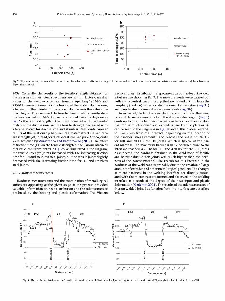
Fig. 3. The hardness distributions of ductile iron–stainless steel friction welded
riction welded ductile iron with various matrix microstructures: (a) flash diameter,
microhardness distributions in specimens on both sides of the weldinterface are shown in Fig 3. The measurements were carried outboth in the central axis and along the line located 2.5 mm from theperiphery (surface) for ferritic ductile iron–stainless steel (Fig. 3a),and bainitic ductile iron–stainless steel joints (Fig. 3b).
As expected, the hardness reaches maximum close to the inter-face and decreases very rapidly in the stainless steel region (Fig. 3).Contrary to this, the hardness decrease in ferritic and bainitic duc-tile iron is much slower and exhibits some kind of plateau. Ascan be seen in the diagrams in Fig. 3a and b, this plateau extendsto 5 or 8 mm from the interface, depending on the location ofthe hardness measurements, and reaches the value of 199 HVfor BDI and 200 HV for FDI joints, which is typical of the par-ent material. The maximum hardness value obtained close to theinterface reached 450 HV for BDI and 470 HV for the FDI joints.As expected, the hardness obtained in the weld zone of ferriticand bainitic ductile iron joints was much higher than the hard-ness of the parent material. The reason for this increase in thehardness at the weld zone is probably due to the creation of largeamounts of carbides and other metallurgical products. The changesof micro hardness in the welding interface are directly associ-ated with the microstructure formed and observed in the welding
interface as a result of the degree of the heat input and plasticdeformation (Özdemir, 2003). The results of the microstructures offriction welded joined as function from the interface are describedbelow.0
50
100
150
200
250
300
350
400
450
500
5.75
4.55
3.35
2.15
0.95
0.15
1.55
3.05
4.55
5.95
7.35
8.45
9.65
10.8
5
Distance (mm )
BDI 2.5mm
BDI in axis
Bondli
ne 1
Bondli
ne 2
b
SS BDI BDI
joints: (a) for ferritic ductile iron-FDI, and (b) for bainitic ductile iron-BDI.
R. Winiczenko, M. Kaczorowski / Journal of Materials Processing Technology 213 (2013) 453– 462 457
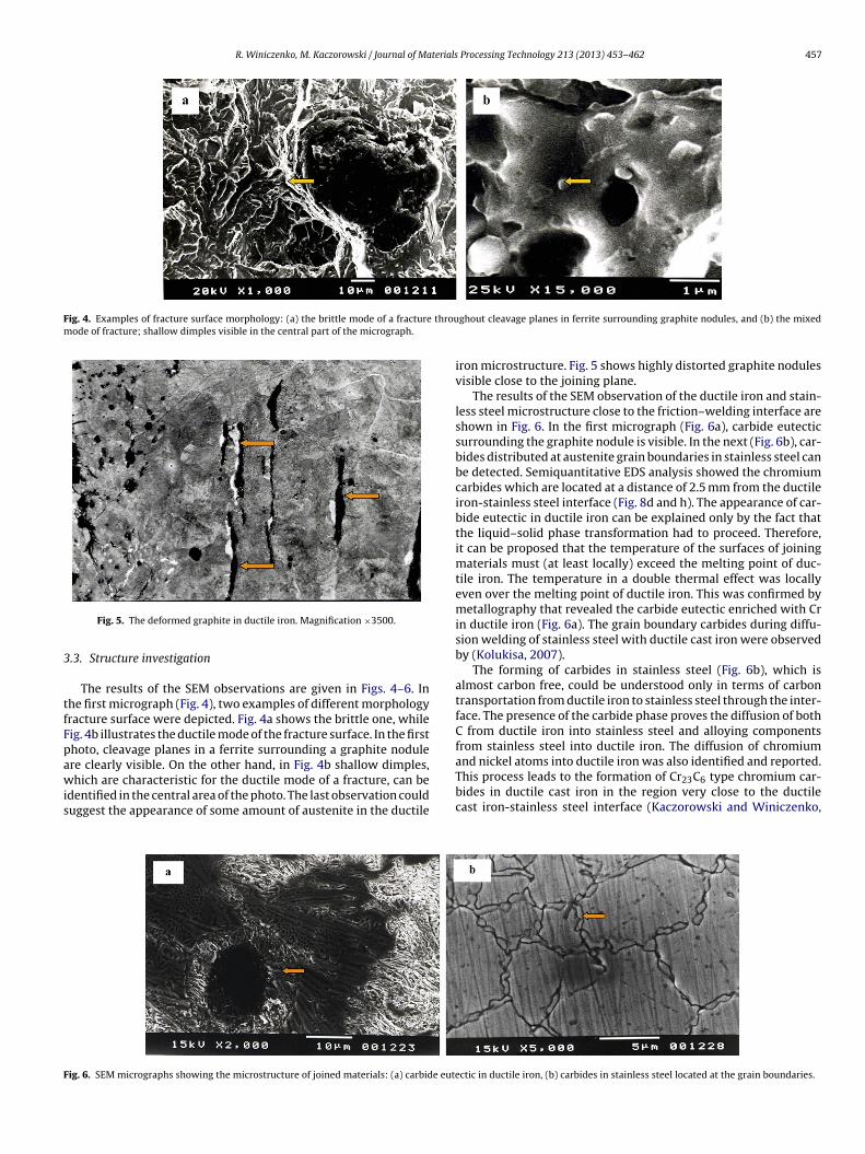
Fig. 4. Examples of fracture surface morphology: (a) the brittle mode of a fracture throumode of fracture; shallow dimples visible in the central part of the micrograph.
3
tfFpawis
F
Fig. 5. The deformed graphite in ductile iron. Magnification ×3500.
.3. Structure investigation
The results of the SEM observations are given in Figs. 4–6. Inhe first micrograph (Fig. 4), two examples of different morphologyracture surface were depicted. Fig. 4a shows the brittle one, whileig. 4b illustrates the ductile mode of the fracture surface. In the firsthoto, cleavage planes in a ferrite surrounding a graphite nodule
re clearly visible. On the other hand, in Fig. 4b shallow dimples,hich are characteristic for the ductile mode of a fracture, can bedentified in the central area of the photo. The last observation coulduggest the appearance of some amount of austenite in the ductile
ig. 6. SEM micrographs showing the microstructure of joined materials: (a) carbide eute
ghout cleavage planes in ferrite surrounding graphite nodules, and (b) the mixed
iron microstructure. Fig. 5 shows highly distorted graphite nodulesvisible close to the joining plane.
The results of the SEM observation of the ductile iron and stain-less steel microstructure close to the friction–welding interface areshown in Fig. 6. In the first micrograph (Fig. 6a), carbide eutecticsurrounding the graphite nodule is visible. In the next (Fig. 6b), car-bides distributed at austenite grain boundaries in stainless steel canbe detected. Semiquantitative EDS analysis showed the chromiumcarbides which are located at a distance of 2.5 mm from the ductileiron-stainless steel interface (Fig. 8d and h). The appearance of car-bide eutectic in ductile iron can be explained only by the fact thatthe liquid–solid phase transformation had to proceed. Therefore,it can be proposed that the temperature of the surfaces of joiningmaterials must (at least locally) exceed the melting point of duc-tile iron. The temperature in a double thermal effect was locallyeven over the melting point of ductile iron. This was confirmed bymetallography that revealed the carbide eutectic enriched with Crin ductile iron (Fig. 6a). The grain boundary carbides during diffu-sion welding of stainless steel with ductile cast iron were observedby (Kolukisa, 2007).
The forming of carbides in stainless steel (Fig. 6b), which isalmost carbon free, could be understood only in terms of carbontransportation from ductile iron to stainless steel through the inter-face. The presence of the carbide phase proves the diffusion of bothC from ductile iron into stainless steel and alloying componentsfrom stainless steel into ductile iron. The diffusion of chromium
and nickel atoms into ductile iron was also identified and reported.This process leads to the formation of Cr23C6 type chromium car-bides in ductile cast iron in the region very close to the ductilecast iron-stainless steel interface (Kaczorowski and Winiczenko,ctic in ductile iron, (b) carbides in stainless steel located at the grain boundaries.

458 R. Winiczenko, M. Kaczorowski / Journal of Materials Processing Technology 213 (2013) 453– 462
Fig. 7. EDS-analysis of Cr and Ni distribution across the interface in the axis and 7.5 mm from the center of ferritic ductile iron-stainless steel joint: (a) bondline 1 as firstcycle welding and bondline 2 as second cycle welding, (b) the weld flash macrograph with area of analysis, (c) the EDS spectrum obtained from FDI at the place marked as agreen triangle in (b), and (d) from SS at the place marked as a yellow point in Fig 7b.
terials
2i
dFmoab
3
oBaTtow
bsdabhc
Fcfst
R. Winiczenko, M. Kaczorowski / Journal of Ma
013). According to many authors, this diffusion is the main bond-ng mechanism in the rotary friction welding process.
The diffusion of chromium and nickel from stainless steel touctile iron could explain the ductile mode of fracture shown inig. 4b. The formation of isolated areas of pearlite in an austeniteatrix was observed in a previous report (Winiczenko, 2001). In
ther areas, approximately 2 mm from the interface, a grid of ferritegainst a background of pearlite was revealed. It runs at the grainoundaries, which are easy paths for the diffusion of carbon atoms.
.4. EDX–SEM investigation
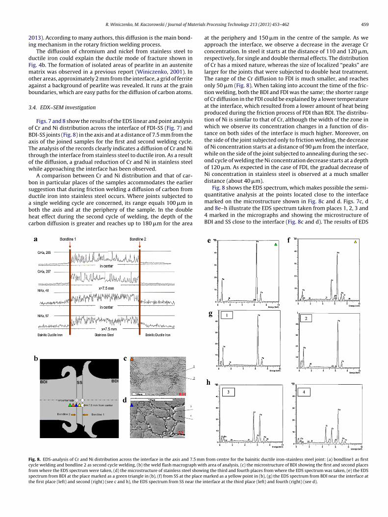
Figs. 7 and 8 show the results of the EDS linear and point analysisf Cr and Ni distribution across the interface of FDI-SS (Fig. 7) andDI-SS joints (Fig. 8) in the axis and at a distance of 7.5 mm from thexis of the joined samples for the first and second welding cycle.he analysis of the records clearly indicates a diffusion of Cr and Nihrough the interface from stainless steel to ductile iron. As a resultf the diffusion, a gradual reduction of Cr and Ni in stainless steelhile approaching the interface has been observed.
A comparison between Cr and Ni distribution and that of car-on in particular places of the samples accommodates the earlieruggestion that during friction welding a diffusion of carbon fromuctile iron into stainless steel occurs. Where joints subjected to
single welding cycle are concerned, its range equals 100 �m inoth the axis and at the periphery of the sample. In the doubleeat effect during the second cycle of welding, the depth of thearbon diffusion is greater and reaches up to 180 �m for the area
ig. 8. EDS-analysis of Cr and Ni distribution across the interface in the axis and 7.5 mmycle welding and bondline 2 as second cycle welding, (b) the weld flash macrograph withrom where the EDS spectrum were taken, (d) the microstructure of stainless steel showinpectrum from BDI at the place marked as a green triangle in (b), (f) from SS at the place mhe first place (left) and second (right) (see c and h), the EDS spectrum from SS near the in
Processing Technology 213 (2013) 453– 462 459
at the periphery and 150 �m in the centre of the sample. As weapproach the interface, we observe a decrease in the average Crconcentration. In steel it starts at the distance of 110 and 120 �m,respectively, for single and double thermal effects. The distributionof Cr has a mixed nature, whereas the size of localized “peaks” arelarger for the joints that were subjected to double heat treatment.The range of the Cr diffusion to FDI is much smaller, and reachesonly 50 �m (Fig. 8). When taking into account the time of the fric-tion welding, both the BDI and FDI was the same; the shorter rangeof Cr diffusion in the FDI could be explained by a lower temperatureat the interface, which resulted from a lower amount of heat beingproduced during the friction process of FDI than BDI. The distribu-tion of Ni is similar to that of Cr, although the width of the zone inwhich we observe its concentration changes in a function of dis-tance on both sides of the interface is much higher. Moreover, onthe side of the joint subjected only to friction welding, the decreaseof Ni concentration starts at a distance of 90 �m from the interface,while on the side of the joint subjected to annealing during the sec-ond cycle of welding the Ni concentration decrease starts at a depthof 120 �m. As expected in the case of FDI, the gradual decrease ofNi concentration in stainless steel is observed at a much smallerdistance (about 40 �m).
Fig. 8 shows the EDS spectrum, which makes possible the semi-quantitative analysis at the points located close to the interface
marked on the microstructure shown in Fig. 8c and d. Figs. 7c, dand 8e–h illustrate the EDS spectrum taken from places 1, 2, 3 and4 marked in the micrographs and showing the microstructure ofBDI and SS close to the interface (Fig. 8c and d). The results of EDSfrom centre for the bainitic ductile iron-stainless steel joint: (a) bondline1 as first area of analysis, (c) the microstructure of BDI showing the first and second placesg the third and fourth places from where the EDS spectrum was taken, (e) the EDSarked as a yellow point in (b), (g) the EDS spectrum from BDI near the interface atterface at the third place (left) and fourth (right) (see d).
460 R. Winiczenko, M. Kaczorowski / Journal of Materials Processing Technology 213 (2013) 453– 462
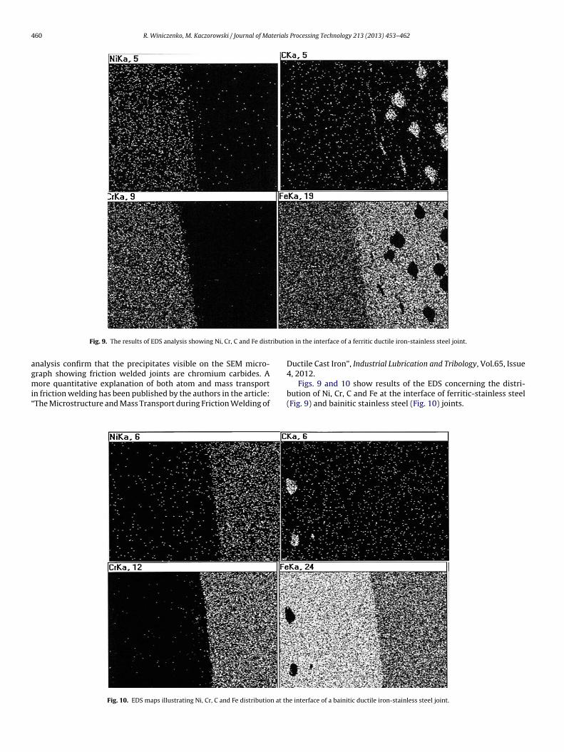
ributi
agmi“
Fig. 9. The results of EDS analysis showing Ni, Cr, C and Fe dist
nalysis confirm that the precipitates visible on the SEM micro-raph showing friction welded joints are chromium carbides. A
ore quantitative explanation of both atom and mass transportn friction welding has been published by the authors in the article:The Microstructure and Mass Transport during Friction Welding of
Fig. 10. EDS maps illustrating Ni, Cr, C and Fe distribution at th
on in the interface of a ferritic ductile iron-stainless steel joint.
Ductile Cast Iron”, Industrial Lubrication and Tribology, Vol.65, Issue4, 2012.
Figs. 9 and 10 show results of the EDS concerning the distri-bution of Ni, Cr, C and Fe at the interface of ferritic-stainless steel(Fig. 9) and bainitic stainless steel (Fig. 10) joints.
e interface of a bainitic ductile iron-stainless steel joint.

terials
cobtitpobttdogtcdiorrm
itcfatlaapriCtfwsIvthogtbifiisb
octcstwfmsi
R. Winiczenko, M. Kaczorowski / Journal of Ma
Using the results of these EDS studies as a basis, it can be con-luded that, where ferritic ductile iron (FDI) is concerned, carbonccurs in the form of graphite clusters (nodules) only, while inainitic ductile iron (BDI) carbon also forms as carbides and canhen be treated as “more uniform” than FDI. During friction weld-ng, the nodular graphite particles in the ductile iron are deformedo give ellipsoids, or are flattened at least in certain places. Thesehenomena were observed by (Mitelea et al., 2010). The presencef graphite lubricated layers in the case of FDI, which may thene purely physical barriers that act on the principle of a discon-inuity structure. The graphite bodies present at the interface inhe form of clusters (Fig. 5) act as a lubricant and therefore pro-uce insufficient heat from friction. Consequently, the propertiesf mechanical joints at the interface are reduced significantly. Thereater the amount of deformed graphite in the case of FDI, thehicker layer of graphite at the interface, and thus it is more diffi-ult for both cross-diffusion and the possibility to create a joint.Theepth of Cr atom penetration into ductile iron is substantially larger
n ferritic ductile iron than in bainitic iron samples. Concentrationf nickel in ductile iron with a bainitic matrix is larger than in fer-itic matrix ductile iron. These observations are consistent with theesults of the EDS linear microanalysis and confirm the results oficrohardness changes at the interface.The results clearly showed that the friction welding process
s inherent to the process of the transport of C, Cr and Ni atomshrough the steel-ductile iron interface. As a result of this pro-ess there is an enrichment of cast iron with Ni atoms, which thenorms a solid solution with iron and probably, at least locally, has
FCC lattice structure. At the same time, the diffusion of Cr leadso the formation of chromium carbides in stainless steel (Fig. 8d),ocated near the sample interface and in some cases found alsos carbides in the carbide eutectic in ductile iron (Fig. 8c). It waslso found that the intensity of the diffusion process was moreronounced during the friction welding of stainless steel with BDIather than FDI. This is evidenced by a larger diffusion range, whichs known to be directly related to the time and diffusion coefficient.onsidering the identical time of friction welding of BDI and FDI,he difference in the depth of diffusion can only result from dif-erent diffusion coefficients. Although the metal matrix of frictionelded ductile iron is different, it is highly unlikely that it could sub-
tantially affect the value of diffusion coefficients of the elements.t is, however, possible that the type of metal matrix affects thealue of the friction coefficient. When considering that both duc-ile irons have the same content of C, it is easy to see that the FDIas a larger share of graphite than the BDI, in which at least 0.8%f carbon appears as a carbide phase. Moreover, it is known thatraphite has excellent lubricating properties. If so, we can expecthat the amount of heat generated during the welding of FDI maye substantially reduced. This in turn means less heat in the friction
nterface zone, thus a lower temperature and lower diffusion coef-cient. A factor promoting a higher diffusivity of a bainitic matrix
s the larger share of easy diffusion paths due to greater disper-ion of a microstructure (a larger amount of grain and interphaseoundaries).
The high intensity of the diffusion process in friction weldingf bainitic ductile iron (BDI) is caused by a much higher dislo-ation density, which results from the plastic deformation thatakes place during friction welding. This increase of diffusivity isaused by pipe diffusion in the dislocation network of predeformedamples. Also, the penetration of diffusion is deeper in the plas-ic deformation material than in annealed material (as the firstelding cycle).Another explanation for the smaller range of dif-
usion of Cr and Ni from the SS to FDI, when compared to BDI,ay be the larger shortening of FDI samples, due to the lower yield
tress of FDI than BDI. If it is assumed that during friction weld-ng both samples are heated to the same temperature, the plastic
Processing Technology 213 (2013) 453– 462 461
deformation for the FDI joints will be greater than BDI when upsetby the same force. A greater shortening of the specimens preventsmetallic contact between the joining parts due to the material flowof FDI to flash, which would explain the smaller range of diffu-sion. However, both the shortening and diameter of flashes wasless for FDI than BDI joints (Fig. 2a); and this above explanationcannot therefore be accurate. Moreover, the smaller shortening andsmaller diameters of the weld flashes, where the friction weldingof FDI is concerned, indicates a lower temperature at the interfacethan that obtained at the BDI joints.
Another factor influencing the diffusion process is the presenceof graphite layers. This layer may act simply as a physical barrierin terms of a microstructure discontinuity. Graphite has excellentlubricating properties, resulting from easy sliding in hexagonal(0 0 0 1) planes. The easy sliding follows from the fact that theseplanes are bonded by very weak Van der Waals bonds (MetalsHandbook, 8th ed., vol. 1). This greatly facilitates the distribution ofgraphite on the surfaces of welded elements. In addition to reducingthe friction coefficient, a very thin graphite layer can substantiallydecrease the strength and even can make the bonding betweenjoined parts impossible. If it is, therefore, assumed that there is afull join during friction welding then, after taking into considerationthe share of graphite on the interface (around 10% of the surface inthe case of FDI) and its almost zero tensile strength, it is easy tounderstand the negative effects of graphite on the tensile strengthof the joints. This negative impact will be stronger the greater theshare of graphite on the surface of the joined elements.
4. Conclusions
The analysis of the microstructure, mechanical propertiesand distribution of elements across the interface of ductileiron and stainless steel allowed us to propose the followingconclusions:
Friction welding is accompanied by a transport of atoms inboth directions across the ductile iron-stainless steel interface. Thisresults in the enrichment of stainless steel with carbon, and duc-tile iron with chromium and nickel atoms. Stainless steel carbonenrichment results in the formation of chromium carbides that aredistributed mostly at the grain boundaries. Iron enrichment in Crand Ni resulted in the creation of an alloy ferrite. Cr was found alsoin a carbide eutectic.
The range of Cr and Ni diffusion in iron generally does not exceed50 �m. The depth of the diffusion of carbon in the case of a jointsubjected to a double thermal effect is 150 �m and higher than fora sample subjected to one step friction welding.
The intensity of diffusion processes during friction welding ofbainitic ductile iron is larger than for ferritic ductile iron.
Acknowledgment
This work was supported by The State Committee for ScientificResearch under Grant 7T08B05519. The authors wish also to thankprofessors Eugeniusz Ranatowski and Stanislaw Dymski from theFaculty of Mechanics of Bydgoszcz Technical University (Poland)for their valuable suggestions.
References
American Welding Society, 1989. Specifications and standards. In: RecommendedPractice for Friction Welding. American Welding Society, Miami.
Arivazhagan, N., Singh, S., Prakash, S., Reddy, G.M., 2011. Investigation on AISI304 austenitic stainless steel to AISI 4140 low alloy steel dissimilar joints by
gas tungsten arc electron beam and friction welding. Materials and Design 32,3036–3050.Celik, S., Ersozlu, I., 2009. Investigation of the mechanical properties and microstruc-ture of friction welded joints between AISI 4140 and AISI 1050 steels. Materialsand Design 30, 970–976.
4 terials
C
D
D
K
K
L
M
MMM
M
H
N
O
O
Ö
Ö
tile iron. Warsaw University of Technology. Doctoral Dissertation. Warsaw,
62 R. Winiczenko, M. Kaczorowski / Journal of Ma
heng, C.P., Lin, H.M., Lin, J.C., 2010. Friction stir welding of ductile iron and lowcarbon steel. Science and Technology of Welding & Joining 15 (8), 706–711.
ette, M., Hirsch, J., 1990. Reibschweissen von Konstruieren aus Kugelgraphitgussmit Stahlteilen. Schweissen und Schneiden 42 (11), 188–190.
ey, H.C., Ashfag, M., Bhaduri, A.K., Rao, K.P., 2009. Joining of titanium to 304L stain-less steel by friction welding. Journal of Materials Processing Technology 209,5862–5870.
aczorowski, M., Winiczenko, R., 2013. The microstructure and mass transport dur-ing friction welding of ductile cast iron. Industrial Lubrication and Tribology 65(4). http://www.emeraldinsight.com/journals.htm?articleid=17047124
olukisa, S., 2007. The effect of the welding temperature on the weldability in diffu-sion welding of martensitic (AISI 420) stainless steel with ductile (spheroidalgraphite-nodular) cast iron. Journal of Materials Processing Technology 186,33–36.
ebedev, V.K., Chernenko, I.A., 1992. Welding and surface reviews. Friction Welding.E. O. Paton Electric Welding Institute.
atsugi, K., Konishi, M., Yanagisawa, O., Kiritani, M., 2004. Joining of spheroidalgraphite cast iron to stainless steel by impact-electric current discharge joining.Journal of Materials Processing Technology 150, 300–308.
etals Handbook, 8th ed., vol.1.etals Handbook, 9th ed., vol. 6. ASM, Metal Park, Ohio, 1993.eshram, S.D., Mohandas, T., Reddy, G.M., 2007. Friction welding of dissimilar pure
metals. Journal of Materials Processing Technology 184, 330–337.itelea, I., Craciunescu, C.M., Gugu, R., 2010. Interfacial behaviour of dissimilar fric-
tion welded nodular cast irons with low carbon steels. Materials Science Forum638–642, 3757–3762.
areyama, T., Nitta, T., Kitagawa, M., Horie, H., 2007. Microstructure and mechan-ical properties of pipe shaped spheroidal graphite cast iron bonded by frictionwelding method. Journal of Japan Foundry Engineering Society 79 (3), 146–150.
akamura, M., Sawada, Y., Sato, Y.S., 2010. Metallographic study of lapped FSWbetween ductile cast iron and austenite type stainless steel. Materials ScienceForum 638-642, 1197–1202.
chi, H., Kawai, G., Morikawa, K., Yamamoto, Y., Suga, Y., 2007. Macrostructure andtemperature distribution near the weld interface in friction welding of cast iron.Strength. Fracture and Complexity 5, 79–88, 2009.
gara, T., Kojoh, K., Nagayoshi, H., 2005. Relation between tensile characteristicsand macrostructure of joint in friction welded ductile cast iron. Journal of JapanFoundry Engineering Society 77, 39–43.
zdemir, N., 2003. Effect of graphite shape in vacuum-free diffusion bonding of
nodular cast iron with gray cast iron. Journal of Materials Processing Technology141, 228–233.zdemir, N., 2005. Investigation of the effect of the mechanical properties of fric-tion welded joints between AISI 304L AISI steel as a function rotational speed.Materials Letters 59, 2504–2509.
Processing Technology 213 (2013) 453– 462
Reddy, G.M., Ramana, P.V., 2012. Role of Nickel as an interlayer in dissimilarmetal friction welding of maraging steel to low alloy steel. Journal of MaterialsProcessing Technology 212, 66–77.
Richter, H., Palzkill, A., 1985. Applicability of test result from miniature frictionwelded specimens to full-size specimens as demonstrated by the combinationof constructional steel and spheroidal graphite cast iron. Welding and Cutting37, 60–65.
Seli, H., Ismail A.I.Md. Rachman, E., Ahmad, Z.A., 2010. Mechanical evaluation andthermal modelling of friction welding of mild steel and aluminium. Journal ofMaterials Processing Technology 210, 1209–1216.
Sahin, M., 2005. Joining with friction welding of high-speed steel and medium-carbon steel. Journal of Materials Processing Technology 168, 202–210.
Sahin, M., 2009. Joining of stainless steel and copper materials with friction welding.Industrial Lubrication and Tribology 61 (6), 319–324.
Sahin Ahmet, Z., Yibas Bakir, S., Ahmed, M., Nickel, J., 1998. Analysis of the frictionwelding process in relation to the welding of copper and steel bars. Journal ofMaterials Processing Technology 82, 127–136.
Satyanarayana, V.V., Reddy, M.G., Mohandas, T., 2005. Dissimilar metal frictionwelding of austenitic–ferritic stainless steels. Journal of Materials ProcessingTechnology 160, 128–137.
Shinoda, T., Endo, S., Tanada, K., 1996. Friction welding of cast iron and stainlesssteels. Welding Internship 10 (12), 929–936.
Shinoda, T., Endo, S., Kato, Y., 1999. Friction welding of cast iron and stainless steels.Welding Internship 13 (2), 89–95.
Song, Y., Liu, Y., Zhu, X., Yu, S., Zhang, Y., 2008. Strength distribution at interface ofrotary-friction-welded aluminum to nodular cast iron. Transactions of Nonfer-rous Metals Society of China 18, 14–18.
Lancaster, J., 1987. Metallurgy of Welding. Allen and Unwin, London.Sunay, T.Y., Sahin, M., Altintas, S., 2009. The effects of casting and forg-
ing processes on joint properties in friction-welded AISI 1050 and AISI304 steels. International Journal of Advanced Manufacturing Technology 44,68–79.
Taban, E., Gould, J.E., Lippold, J.C., 2010. Dissimilar friction welding of 6061-T6 alu-minum and AISI 1018 steel properties and microstructural characterization.Materials and Design 10, 2305–2311.
Winiczenko, R., Kaczorowski, M., 2012. Friction welding of ductile cast iron usinginterlayers. Materials and Design 34, 444–451.
Winiczenko, R., 2001. The structure and properties of friction welded duc-
Poland.Zimmerman, J., Włosinski, W., Lindemann, Z.R., 2009. Thermo-mechanical and dif-
fusion modelling in the process of ceramic-metal friction welding. Journal ofMaterials Processing Technology 209, 1653–1664.