fpl design for lumber dry kiln using solar/wood energy in … · 2005-07-14 · fpl design for...
TRANSCRIPT

United StatesDepartment ofAgriculture FPL Design forForest Service
ForestProductsLaboratory
GeneralTechnloal
FPL-44
Lumber Dry Kiln UsingSolar/Wood Energyin Tropical LatitudesJohn L. TschernitzWilliam T. Simpson

Developing countries with a timber resource that canbe manufactured into finished products either for localuse or export often lack the capital to build high-costdry kilns. Many of these countries are in the tropicswhere solar radiation and ambient temperatures arehigh. The low-cost solar/wood energy lumber dry kilndescribed in this report was designed and tested by theForest Products Laboratory (FPL) for such countrieswhere solar dry kilns can be built and operated at lowcost.
The FPL design is for a 6,000-fbm capacity kiln havingan insulated drying compartment, an externalhorizontal solar collector, and a furnace roomcontaining a wood burner. Capacities larger or smallerthan 6,000 fbm are also possible. This design allowscollector and wood burner sizing to match the energydemands of the dryer. The design also incorporateslow-cost controls that allow unattended drying whenoperated as a solar-only dryer. Manual firing isnecessary when the wood-burning system is supplyingthe energy.
This kiln design is the final, commercial-size versionestablished after years of testing several 1,000-fbmcapacity prototypes. In December 1984 a kiln of thisdesign was built in Sri Lanka at a factory thatmanufactures furniture and laminated beams fromrubber and coconut wood.
Keywords: Solar, solar drying, wood energy, dry kiln,tropics, dryer.
April 1985
Tschernitz, John L.; Simpson, William T. FPL design for lumber dry kilnusing solar/wood energy in tropical Iatitudes. Gen. Tech. Rep. FPL-44.Madison, Wl: U.S. Department of Agriculture, Forest Service, ForestProducts Laboratory; 1985.17 p.
A limited number of free copies of this publication are available to thepublic from the Forest Products Laboratory, P.O. Box 5130, Madison, WI53705. Laboratory publications are sent to over 1,000 libraries in theUnited States and elsewhere.
The Laboratory is maintained in cooperation with the University ofWisconsin.

FPL Design forLumber Dry KilnUsingSolar/Wood Energyin TropicalLatitudesJohn L. Tschernitz, Chemical EngineerWilliam T. Simpson, Supervisory Research ForestProducts Technologist
Forest Products Laboratory, Madison, WI
Introduction
In 1975 the Forest Products Laboratory (FPL) begandesigning and testing low-cost solar dry kilns for small-to medium-sized production facilities in tropicaldeveloping countries. Several kiln designs wereproposed, and one was selected from which threesmall-capacity prototypes were built and tested foroperation and durability. This design was ultimatelyoptimized so that a commercial-size kiln design couldbe proposed, a detailed description of which iscontained in this report.
The project began when the U.S. Agency forInternational Development (USAID) asked FPL toinvestigate the use of solar energy to improve thedrying practices of small- and medium-scale producersin developing countries, and to propose a kiln design ifthe technology was feasible, which it was (Tschernitzand Simpson 1977). We built a 1,000-fbm prototype atMadison, Wis. in 1977 (Simpson and Tschernitz 1984,Tschernitz and Simpson 1979) and tested it everysummer since.
In 1981 we assisted in building a 1,000-fbm prototypefunded by USAID, SRI LANKA, at a furniture factory inSri Lanka, and it has been operating successfully sincethen (Simpson and Tschernitz 1982). In 1982 weassisted in installing another solar kiln of the samedesign funded by the United Nations Food andAgriculture Organization (UNFAO) at the ForestResearch Institute at Yezin, Burma (fig. 1).
The design described in this report, along with theexisting prototype, will provide the full kiln-dryingneeds of the furniture factory located near Horana inthe southwestern quarter of Sri Lanka, 7° N latitude.
While the size chosen matches the factory’s needs, thedesign can be built in smaller or larger versions. Inearly 1984 FPL signed an agreement with Borwood Ltd.of Colombo, Sri Lanka, with funding from the UnitedNations Development Program (UNDP), to provide thedesign details and technical consultation forconstruction, startup, and operation of the kiln, whichwas completed in December 1984.
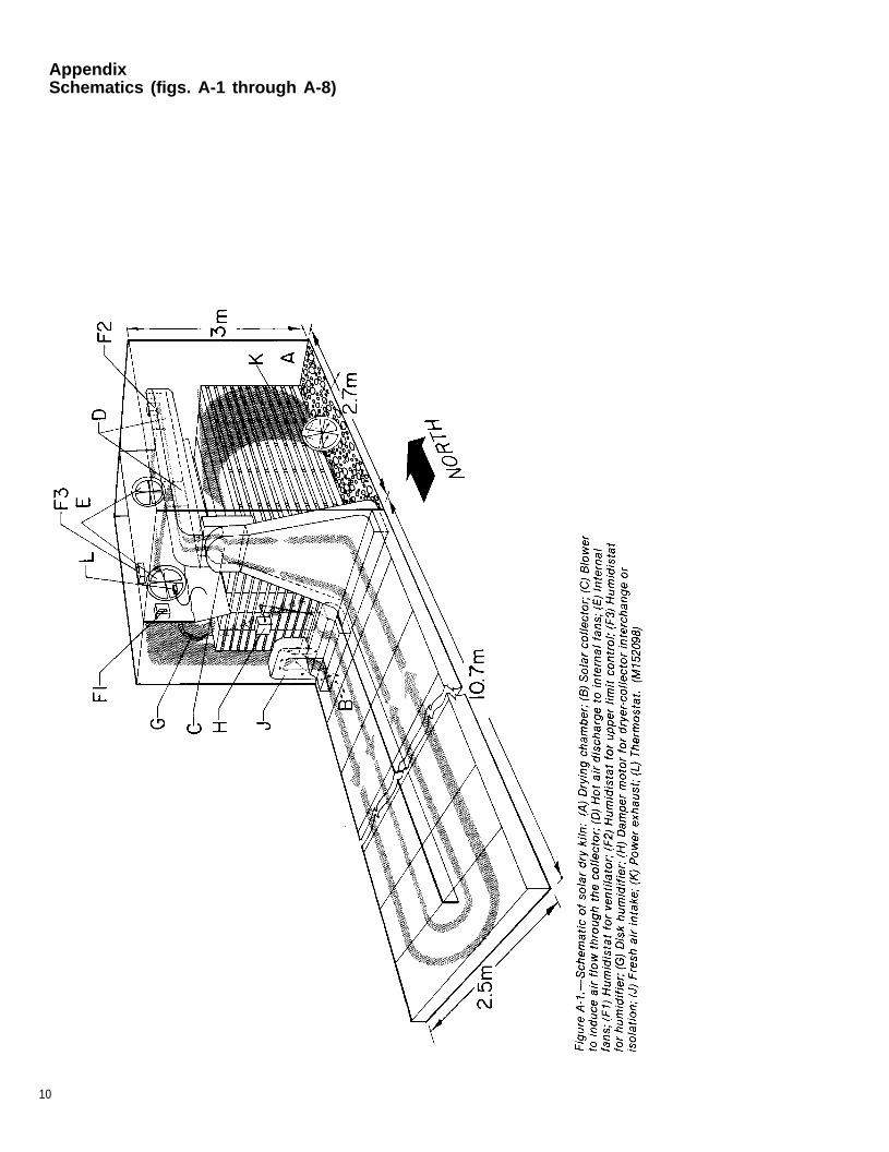
A schematic diagram of the prototype kiln is shown infigure A-1. The caption is keyed to labeled kilncomponents in enough detail to illustrate the generaloperation of the kiln.
Figure 1.— 1,000-fbm (2.4-m3) capacity solar kilnat Forest Research Institute, Yezin, Burma.(M152096-1)

Description of the Dryer
General Principles of OperationA schematic of the proposed dryer design is shown infigure A-2. It differs from the prototype in several ways:1) the capacity is increased from 1,000 fbm (2.4 m3) toapproximately 6,000 fbm (14 m3) of 1-inch- (25-mm) thicklumber with 3/4-inch (19-mm) stickers; 2) four collectors,instead of one, are located side-by-side delivering airinto one large drying chamber; and 3) a wood residueburner has been added to allow drying 24 hours per dayindependent of solar insolation levels.
Air circulates through two intersecting loops, onethrough the collectors and/or residue burner, and theother through the wood package (fig. A-2). The woodpackage handles twice the flow volume of thecollectors, which are two independent pairs of twoparallel collectors. Airflow in each half of a collectorpair is counter to the flow in the other half so that onlyone duct (C-fig. A-4) is necessary to carry air from thepaired collectors to the manifold (D-fig. A-2). The fourexhausters (K-fig. A-2) remove air (containingevaporated water) from the kiln at the leaving-air side(high humidity) of the wood package. The makeup airfrom outside enters the system at four points (J-fig. A-2)through the collectors (B-fig. A-2). This is done forthree reasons: 1) the cooler ambient air lowers thetemperature in the collector, and thus heat losses aredecreased; 2) after the solar energy input no longermaintains the collector above dryer temperatures, thestored energy (collector above ambient temperature)can be used to preheat the incoming air; 3) the ambienttemperature of the outside air with its lower humiditycan purge the collector of high-humidity dryer air andthereby prevent or reduce condensation within thecollector, particularly at night, which will increase itsefficiency (energy is required to re-evaporate water atthe beginning of the next diurnal cycle).
Heated air from the collectors is pulled into the dryerby two blowers (C-fig. A-2) and discharged (D-fig. A-2)directly into four overhead fans (E-fig. A-2) thatcirculate air through the stacked lumber.
Automatic control of the solar dryer is desirable, at theleast possible cost, in order to accommodate 1) theintermittent delivery of solar energy to the collector;2) variable relative humidities (RH) within the dryingchamber, which will depend upon the ambient humidityand temperature in the chamber; and 3) the variablerate of drying of the wood. Without such controls,almost continuous manual observation would beneeded to approach the quality and efficiency of dryingattainable with automatic control. Controls include1) two differential thermal comparators (Fc,Fd-fig. A-2)to sense the difference between dryer and collectortemperatures and turn the solar blowers (C-fig. A-2) onand off accordingly; 2) a humidistat (RH1-fig. A-2) toallow automatic venting as needed because controlledventing increases thermal efficiency and also permitsscheduling high RH’s early in drying and low RH’s later
on; 3) a second humidistat (RH2-fig. A-2) to establish amaximum RH above which the dryer will shut down.This might happen during long periods of low-solarinput and high humidities, i.e. rainy periods, and isparticularly important when the wood is below20 percent moisture content; and 4) a third humidistat(RH3-fig. A-2) has two functions: a) control thehumidifier (G-fig. A-2) for conditioning at the end of thedrying run, and b) raise the relative humidity in thedrying chamber in order to prevent or reduce degrade inrefractory woods at intermediate moisture contents.
A low-cost combustion system fueled by wood hasbeen incorporated in the solar dryer design. A simpleburner is located in a furnace chamber on the oppositeside of the drying compartment from the solar collector(A-fig. A-2). The furnace can operate eithersimultaneously or separately from the solar collector.
Construction Details of the DryerFigures A-3 through A-8 provide a description of theimportant construction details of the kiln:
Figure A-3 - Plan view of entire kilnFigure A-4 - Section view of entire kilnFigure A-5 - Section view of solar collector ductsFigure A-6 - Section view of solar collectorFigure A-7 - Elevation view of furnace roomFigure A-8 - Wiring diagram of control system
Solar collector (fig. A-6). —The colIector is external tothe drying compartment so that collector area andorientation are not limited by the geometry of the dryer.The collector is horizontal (except for a 1/2 degreenorth-south drainage tilt) and is built into the groundfor ease and low cost of construction. The horizontalorientation is particularly effective near the equator.
Figure A-6 is an end cross section of one of the twopairs of collectors. A foundation of concrete blocks orpoured concrete form the perimeter of the collector. A12-inch- (0.3-m) deep excavation is filled with gravel toapproximately 6 inches (0.15 m) of the top of the blockor concrete foundation. A layer of charcoal piecessized to 0.5-1 inch (1.3-2.5 cm), about 2-3 inches(5.1-7.6 cm) thick, covers the gravel. Charcoal is aninexpensive energy-absorbing surface and heat-transfermedium and a good insulator that reduces heat loss tothe ground. The interior surfaces of the foundation arepainted flat black. The collector cover spans the 4 feetbetween sections of the foundation.
2

Figure 2.—Glass collector cover on prototypekiln. Wood sills shown in this photo are notincluded in the design of the 6,000-fbm kiln.(M830178-8)
Experience with the prototype indicates that commonwindow glass will be the most cost effective collectorcover, particularly in areas without access to rigidplastic cover material. The sections of glass makingup the cover are installed to overlap (0.5 inch, 1.3 cm)as shingles do (fig. 2). Butyl sealant tape and siliconesealant are used to seal the glass directly to the blockor concrete, foundation. One feature of thisconstruction method is avoidance of the expense andpossible decay of wood frames for the glass.Individual sections of glass are replaceable simply bycutting the sealant around the edges.
The collector is 50 feet (15 m) long, and each section isapproximately 4 feet (1.2 m) wide. Because of overlapat the edges, the effective collector area isapproximately 1,500 square feet (136 m3). The ratio oflumber capacity to collector area is 4 fbm per squarefoot (0.1 m3/m2). In each of the four collectors air isdrawn from the drying compartment and/or fresh airintakes (J-fig. A-2), travels the length of one side of thecollector, crosses over to the other side through the4-foot-long gap at the end, and then travels down thatside fo the collector and back into the dryingcompartment through the ducts shown in figure A-5.Blowers (C-fig. A-2) induce airflow through the collectorand into the drying compartment to the manifold thatdischarges the heated air just behind fans for internalcirculation. The collector is under negative pressure sothat any leakage is into the system.
Drying compartment. —The inside dimensions of thedrying compartment are approximately 10 by 34 by11 feet high (3 by 10.4 by 3.3 m). The kiln is trackloaded and is designed for a 5-foot-wide load of lumber(fig. A-4). The walls are of 12- by 12- by 24-inchconcrete block, hollow and filled with loose insulation.The ceiling of the drying compartment consists of2- by 4-inch (50- by 100-mm) boards on edge (figs.A-4, A-5). This provides good insulation and a solid
ceiling for attachment of fans and other kilncomponents. Above the 2 by 4 ceiling is a built-up roofwith sealed surfaces and space for insulation. Abovethat an open-pitched shed-type roof of corrugated metalpainted black serves the dual role of providing forwater runoff and as a pre-heater for makeup airentering the solar collector(figs. A-2, A-4).
Wood residue burner. —Wood residue is burned in asimple, low-cost burner housed in a furnace chamberon the side of the drying compartment opposite thesolar collector (figs. A-3, A-4, A-7). The burner consistsof two double-wall 55-gallon steel drums mounted on aframework. One drum-is the combustion chamber. Theother, along with the chimney, serve as additional heattransfer surfaces. The burner operates at 65 percentefficiency and can produce up to 80,000 Btu/hour(23 kW) (Anonymous 1981). A blower (fig. A-4)discharges kiln air into the furnace chamber, andforces heated air from the furnace room back through aduct into the drying compartment. When humiditycontrol is necessary, a humidistat (RH3-fig. A-2)-activated water spray can release water into thefurnace chamber for mixing with air going to the dryingcompartment. A manifold within the dryingcompartment distributes heated air into the internalcirculating air.
Table 1 lists the major building materials for the kiln.
Table 1 .—List of major building materials for solar/woodenergy kiln
Item AmountPoured concrete for foundationsand footings 26 yd3 (20 m3)Concrete blocks—12 x 8 x 24 in.(0.31 x 0.20 x 0.62 m) 1,200 blocksRoof-decking boards—2 in. x 4 in.x 11 ft (0.051 x 0.102 x 3.35 m) 205 boardsLoose-fill insulation 625 ft3 (17.7 m3)Kiln coating 1,400 ft2 (130 m2) coveragePlastic film (black) for collector 1,600 ft2 (149 m2)CharcoalGravelNo. 5 concrete-reinforcing barSteel l-beam for furnace roomroof (W8 x 24)Glass (3/16 in. (4.7 mm) thick)Corrugated roof
SteelAsbestos
55-gallon drumsButyl automotive sealantSilicone sealantSteel headerAngle ironSheet metalLumberFasteners
14 yd3 (10.7 m3)9 vd3 (6.9 m3)150 ft (45.7 m)
8.5 ft (2.6 m)1,485 ft2 (138 m2)
532 ft2 (49.4 m2)280 ft3 (26.0 m2)21,200 ft (366 m)120 tubes30 ft (9.1 m)as neededas neededas neededas needed
3

Energy Supply and Demand
Energy supply and demand estimates can be made onan annual basis for the 6,000-fbm kiln for drying1-inch-thick rubberwood in Sri Lanka, as summarized intables 2 and 3. Table 2 summarizes a 7-day dryingschedule, and table 3 contrasts a slower 10-dayschedule where proportionately more solar than woodenergy can be used. There are also many otherpossible similar schedules. In each schedule there arethree sources of energy supply: solar (based on1,500 ft2 of collector operating at 50 pct efficiency),wood residue (one burner rated at 80,000 Btu/hr), andelectrical energy from the fan and blower motors.Assuming that the normal mode of operation will makemaximum use of solar energy for a given schedule andsupplement with wood residue to supply the rest, the7-day schedule will use 41 percent solar, 46 percentwood residue, and 13 percent electric; the 10-dayschedule will use 62 percent solar, 18 percent woodresidue, and 20 percent electric. Thus, if one is willingto increase drying time, use of wood residue can bereduced. If one needs to minimize drying time, thenproportionally more wood residue energy can be used.Electric energy might be reduced by not operating twoof the four fans late in drying when air circulationrequirements are reduced.
Table 2.—Energy supply and demand estimates (averageannual basis) for solarfwood energy dry kiln for operation insouthwestern Sri Lanka, drying 6,000 fbm of 1-inch-thickrubberwood from 60 to 13 percent using a 7-day (168-h)schedule
Energy at times ofSchedule 11
2168 h (pct) 24 h 312 h 41 h
supplySolar (1,500 ft2 collector at
50 pct efficiency) 6.09 (41) 0.87 0.87 0.250Wood residue burner 513.44 (46) 1.92 0.96 0.080Electric (fan/blower motor) 1.99 (13) 0.28 0.14 0.012
Total 21.52 3.07 1.97 0.342
DemandMaximum — 3.21 1.60 0.133Average for 168 hours 15.01 (100) 2.14 1.07 0.089
1Moisture content (pct) temperature (°F) relative humidity (pct)60-50 110 8050-30 120 5030-15 130 3015-13 140 30
2Total drying time to 13 pct moisture content.
3Daylight hours.
Table 3.—Energy supply and demand estimates (averageannual basis) for solar/wood energy dry kiln for operation insouthwestern Sri Lanka, drying 6,000 fbm of 1-inch. thickrubberwood from 60 to 12 percent using a 10-day (240-h)schedule
Energy at times ofSchedule 21
2240 h (pct) 24 h 312 h 41 h
supplySolar (1,500 ft2 collector at
50 pct efficiency)Wood residue burnerElectric (fan/blower motor)
Total
DemandMaximumAverage for 240 hours
1Moisture content (pct) temperature (°F) relative humidity (pct)
2Total drying time to 12 pct moisture content.
3Daylight hours.
4Maximum hourly rate at solar noon.
5If the full 8.70 x 10⁶ Btu of net available solar energy isutilized, then the net wood residue is 2.53 x 10⁶ Btu.
4Maximum hourly rate at solar noon.
5If the full 6.09 x 10⁶ Btu of net available solar energy isutilized, then the net wood residue is 6.93 x 10⁶ Btu.

Control and Operation of the Kiln
The kiln is designed to operate automatically except forthe burner that must be charged manually. A range ofoperating variables can be changed by manipulatingset points. This provides a means to control dryingaccording to a schedule.
Solar-Only Operation
Daily Control SequenceA description of events in a typical 24-hour controlsequence will illustrate how the dryer operates.Following that, a detailed description of the controlequipment and a wiring diagram of the control circuitwill be presented.
0000-0800 hours. -The timer (fig. A-8) opens the controlrelay, and the kiln is turned off.0800 hours. -The timer closes the control relay(R1-fig. A-8) if the RH in the dryer is below the RH2 setpoint (the upper limit of RH set by RH2 in fig. A-2). Theinternal fans are on. The power vents (K-fig. A-2) are onif the RH in the dryer is above RH1 set point.
0800-2200 hours. —The solar blowers (C-fig. A-2, fig. A-8)start when the temperature in the collector (F-fig. A-2)is above the temperature in the drying chamber(Fd-fig. A-2) (Deko Lab control-fig. A-8). Simultaneouswith the solar blower operation, the dampers (H-fig. A-2,fig. A-8) open to permit continuous circulation of airfrom the dryer through the collector and back into thedryer through the duct (D-fig. A-2) behind the fans (E-fig.A-2). When the solar blowers are off, the duct thattakes air from the drying chamber into the collectorsmust be dampered. Dampering prevents the loss ofenergy through induced circulation, by fan head, ofwarm air from the drying chamber through the coolcollector. The electrical input to the solar blowers is infront of the control relay (R1-fig. A-8) so that the solarblowers (C-fig. A-2, fig. A-8) can be activated if theyhave been shut off by high RH (RH2-fig. A-2, fig. A-8).This is important because when sufficient solar energybecomes available to heat the air in the collector, itlowers the RH of the air entering the drying chamber.When the RH falls below the set point (RH2) the dryerturns on automatically.
The differential temperature controls (FC/Fd-fig. A-2,Deko Lab control-fig. A-8) activate the solar blowersintermittently throughout the drying day (times between0800 and 2200, or other time as set by the timer)whenever the temperature in the collector is higherthan the drying chamber. When the solar blowers areOFF, the fans and exhaust blowers will continue tooperate. Drying can proceed without solar heat inputinto the collector because of energy storage in thewood/dryer system, the drying capacity of the ambientair, and the stored energy in the collectors. The storedenergy can be recovered by preheating, i.e., scavengingof the collector with the vent air entry induced by theexhaust blowers.
If the RH falls below set point RH1 (some time between0800 and 2200, or other time as set by the timer), thehumidifier (G-fig. A-2, fig. A-8) is activated by its ownhumidistat (RH3) to increase the RH.
2200-2400 hours. —The dryer will normally stopoperation. Since the dampers (H-fig. A-2, fig. A-8) areclosed (solar blowers have been off) the drying chamberwill be isolated from the collectors and overnight heatloss is minimized. A thermostat is located in parallelwith the timer/relay circuit (fig. A-8). If at 2200 hours (orother time set by the timer) the temperature in thechamber is greater than 90 °F (32 °C), or other variablesetting, the drying will continue until the temperaturedrops below 90 °F (32 °C) or the humidity rises aboveset point RH2. The cycle will be repeated again at0800 hours the next day.
Operating ControlsTimer. —The set points, ON and OFF time for any24-hour day, can be changed to meet local solar dryingconditions. The timer can also be bypassed manually(switch S5-fig. A-8).
Differential temperature switch—Deko Lab. —The solarblowers can be controlled manually by the bypassswitches (S7,S8-fig. A-8). The Deko Lab controls willactivate the solar blowers at collector temperatures inthe difference range of 2 to 20 °F (1.1 to 11 °C)(difference between FC and Fd in fig. A-2, as adjusted bysetscrew) above the dryer temperature. For dryeroperation the differential should be about 5 °F (2.8 °C).(Trial/error set-screw selection).
Relative humidity control. —All set point selection ismanual with the dryer. The set point of RH1 can bechanged continuously from 0 to 100 percent RH. Thisswitch is closed above set point and controls theexhaust blower (an arbitrary scale that can becalibrated for higher accuracy). At temperatures above120 °F (49 °C), a slight temperature shift in this scalewill be noted. Customarily, the set point will be highinitially and low in the final stages of drying,particularly for refractory woods.
RH2 is similar to RH1, except the switch is open (OFF)above set point. The switch controls the power relay.This control is used to maintain humidities below acertain maximum level, which may be necessary duringa series of cloudy days in order to prevent the moistureincrease in the already low-moisture wood.
5

RH3 operates the humidifier (compressor-spray nozzles)and is similar to RH1, except the switch is open (OFF)above set point. The drying chamber can be controlledto maintain the humidity above a minimum level bymeans of this humidifier. In order to humidify, theswitch (S4-fig. A-8) must be closed to activate RH3 forcontrol of the humidifier and solenoid water valve. Thecontrol point on RH3 can be varied over a wide range.If drying stresses are present at the end of the dryingrun, the humidifier can be used to accomplish aconditioning stress relief period. At RH’s in thechamber greater than 85 percent and temperatures inexcess of 110 °F, stress relief can be accomplished in1 to 3 days (solar) depending upon the wood properties,thickness, and/or degree of stress.
Table 4.–Electric switches (refer to fig. A-8)
Switch
S5B
S7, S8
S12, S13, S14, S15
S16, S17
S5
S5A
S6
S4
S4A
S9
S3
S18
S19
S10
RH11
RH21
RH31
Function
Thermostat cutoff (timer bypass)
Line bypass of Deko Lab controls for solarblower
Manual ON/OFF for internal fans
Manual ON/OFF for solar blowers
Timer bypass
ON/OFF timer contact
Bypass RH2
Manual ON/OFF for humidifier
Bypass RH3
Manual ON/OFF for exhaust
Bypass RH1
Furnace blower ON (Position 1) orcontrolled by RH3 (Position 2)
ON/OFF kiln lights
Main disconnect
Honeywell humidistat H404 A 1003Closes on rise of RH above set point
Honeywell humidistat H404 C 1019Opens on rise of RH above set point
Honeywell humidistat H404 C 1019Opens on rise of RH above set point
1Located within solar dryer.
Table 5.–Control panel operational modes (refer to fig. A-8)
Switch Automatic mode Manual modeS5B
S7, S8
S12, S13, S14, S15
S16, S17
S5
S5A
S6
S4
S4A
S9
S3
S181Closed—power ON.
Closed1
Position 6
Closed
Closed
Open
Closed
Open
Closed or open
Open
Closed
Open
Position 2
Open2
Position 5
Closed
Closed
Closed
Open
Closed
Closed
Closed or open
Closed or open
Closed
Position 1 or 2
20pen —power OFF
Air circulation. —Four single-speed fans are controlledby the timer, RH2, thermostat, and manual switches(S12-15-fig. A-8). The fans can be operated together orseparately, and in the later stages of drying when aircirculation requirements decrease, it will beeconomical to switch two of the four fans off forreduced energy consumption.
Control of Various ComponentsTimer— variable ON/OFF by time of day, or manualswitch (S5A-fig. A-8).
Solar blower— Deko Lab TC-3 thermal switch ormanual switches (S7,S8-fig. A-8).
Fans— Timer, RH2, or manually (switches S12-15-fig.A-8).
Exhaust vents— RH1, timer, RH2, or manual switch(S9-fig. A-8).
Humidifier— RH3 or manual switch (S4-fig. A-8).
Dampers— Deko Lab thermal switch or manualswitch (switches S7, S8-fig. A-8).
Furnace blower— RH3 or manual switch (S18-fig. A-8).
Table 4 summarizes the electric switches in the controlsystem (with reference to fig. A-8). Table 5 summarizesswitch positions for automatic or manual operation.Table 6 is a list of required electrical equipment.

Supplemental Wood Fuel Operation
Table 6.—Electrical equipment Iist
Figure 3 Item Quantity
C Solar blower, 18-1/8-inch wheel diameter,3,750 CFM free air delivery at 467 RPM,1 hp, 220 V*, 50 Hz, totally enclosed fan-cooled motor.
E Internal fans, 30-inch-diameter blades,11,000 CFM free air delivery at 690 RPM,1 hp, 220 V*, 50 Hz, totally enclosed fan-cooled motor.
K Exhaust ventilators, 12-inch-diameterblade, 940 CFM free air delivery at 1,500RPM, 1/10 hp, 110 V, 60 Hz, sealedmotor.
Step down auto transformer 220-115 V,1.7 kVA (for exhaust ventilators).
Furnace blower, direct drive, 9-inchwheel diameter, 1,390 CFM at 1-1/2-inchstatic pressure and 1,725 RPM, 1 hp ★ ,220 V, 50 Hz, totally enclosed fan-cooledmotor.
H Honeywell damper motor modelM346A1140, 230 V, 50 Hz.
RH1 Humidistat that switches OFF whenhumidity falls to set point, 220 V.
RH2, RH3 Humidistat that switches ON when humidity falls to set point, 220 V.
F c, F d Differential temperature controller,230 V, 50 Hz.
Timer (24 hr), 230 V, 50 Hz.
Relay (R2-fig. A-8), 1-1/2 hp, 230 V, 50 Hz.
Contacter (R1-fig. A-8), 7-1/2 hp, 230 V,50 Hz.
Solenoid valve (fig. A-8), 230 V, 50-60 Hz.
Compressor for humidifier, 1/2 hp,230 V, 50 Hz, 4-1/2-gallon tank.
Thermostat, remote sensing, SPDT,range should cover at least 30 to 90 °F.
★ Optional 440V, 3ø
2
4
4
1
1
4
1
2
2
1
1
1
1
1
1
A simple wood waste fuel combustion system has beenincorporated into the solar drying system. It consistsof two 55-gallon steel drums, mounted on a framework,as the combustion chamber and heat transfer surfaces(figs. A-2, A-3,A-4, and A-7). The purpose of this adjunctsystem is to increase the drying throughput of the kilnby operating 1) at night, 2) on cloudy days, and3) during rainy periods. The auxiliary furnace canoperate simultaneously with the solar collector in thefollowing way. The solar blower is only activated whenthe collector is warmer than the kiln chamber. Thus, ifthe furnace has heated the drying chamber higher thanthe discharge temperature of the collector, the solarblower will stop and the dampers (H-fig. A-2) will close.Two events then follow: 1) When the RH1 control callsfor venting, fresh air is drawn through the collector tobe preheated (J, B-fig. A-2), thereby recovering any solarenergy accumulating in the collector when the bloweris off, even though the collector is now at a lowertemperature than the dryer. 2) At low vent rates thecollector temperature may again rise above the kiln“control” temperature, and the solar blower will start.The energy input from the furnace will be variedmanually from the maximum to lower levels by dampercontrol of combustion air to the drum and with theamount and quality of fuel charged to the furnace.Observation of temperature in the furnace house and/orthe kiln will guide the operator in the manual firing ofthe combustion chamber. If for some reason thetemperature in the kiln rises to levels felt injurious tothe wood, a discharge vent (furnace heat bypass-fig.A-4) can be opened to cool the system.
The steel drums will probably need to be replacedfrequently because corrosion will perforate the drumwall. This compromise is made with the assumptionthat steel drums are readily available, and that evenwith frequent replacement the cost will be less thanwith a more durable but more expensive burner. If adifferent combustion unit is substituted, the operationof the blockhouse furnace chamber (A-fig. A-2) wouldstill be maintained.
If it is necessary to raise the humidity at certain stagesof the drying cycle (RH3 control), a pneumatic atomizer(G-fig. A-2, fig. A-8) has been installed in the furnacechamber to spray water onto the heated drums. Theevaporated water is then introduced along with theheated air into the kiln. If the furnace is not inoperation when it is necessary to raise the humidity inthe dryer, the atomizer is still activated by RH3. Inaddition, when switch S18 (fig. A-8) is in the correctposition, the furnace blower will also be activated byRH3 so that the humidified air is circulated from thefurnace room to the drying chamber.
Waste wood fuel should be inventoried in order toprovide for air drying and thus more efficientcombustion and higher heat release from the lowermoisture content wood. It may be desirable to use thesolar dryer itself to predry fuel between wood chargesshould the inventory of air-dried fuel be low.
7

Construction of Kiln Summary
In August 1984 kiln control equipment (fans, blowers,motors, various sensors, etc.), and special sealants forthe glass collector, were shipped from the UnitedStates to Sri Lanka. Concurrently, the staff ofBorwood, Ltd. began construction of the kiln structureusing local building materials. In early November, theauthors arrived in Sri Lanka to help in finalconstruction details and assure proper operation. Thekiln was completed in early December. Figure 3 showsthe kiln shortly before completion.
The FPL design for the solar/wood energy dry kilndescribed in this report is the culmination of a projectthat included design, construction, and testing ofseveral small prototype kilns. Observation of prototypeperformance suggested several design changes. Thefinal design is commercial size (for small-medium sizeoperations in tropical developing countries) andincorporates design improvements suggested byprototype performance.
The specific design is for 6,000 fbm (14 m3) capacity,although within practical limits the design is modularin 3,000 fbm (7 m3) increments. The kiln consists ofthree major components: 1) a glass-covered collectorbuilt horizontally into the ground; 2) a separate dryingcompartment; and 3) a furnace room housing a woodresidue burner. The basic design philosophy was toprovide as much automatic control as practical usinglow-cost industrial controls. The combination of solarand wood waste energy allows 24 hours per day dryingregardless of weather.
The design was intended specifically for a furniturelaminated beam factory near Colombo, Sri Lanka. Thekiln was built in December 1984, and is nowoperational.
8

Literature Cited Acknowledgment
Anonymous. The return of the wood stove. ConsumerReports. 46(10); 1981.
Simpson, W. T.; Tschernitz, J. L. Solar dry kiln gets trialin Sri Lanka. World Wood. 23(1): 13; 1982.
Simpson, W. T.; Tschernitz, J. L. Solar dry kiln fortropical latitudes. Forest Products Journal. 34(5): 25-34;1984.
Tschernitz, J. L.; Simpson, W. T. Solar kilns: Feasibilityof utilizing solar energy for drying lumber in developingcountries. USAID FPL-AID-PASA TA (AG 02-75).Washington, DC: U.S. Department of Agriculture, ForestService; 1977.
We thank the following staff at FPL Tedd Mianowski,technician; Doug Hall and Dennis Rose, electricians;and Mike Statz, draftsman, for their valuablecontributions to this project.
In particular, we wish to acknowledge Hope Todd,Director of Borwood, Ltd., for his interest in this projectas well as his management of the financing andconstruction of the solar kiln at Horana; andC. Dassanayake, Engineer at Borwood, for his effectiveefforts in directing the technical details ofconstruction.
Tschernitz, J. L.; Simpson, W. T. Solar-heated, forced-airlumber dryer for tropical latitudes. Solar Energy.22: 563-566; 1979.
9
AppendixSchematics (figs. A-1 through A-8)
10

11


Figure A-4.—Section view of solar/wood residue kiln. (ML845652)

Figure A-5.—Section view of solar collector ducts. (ML845654)


REAR ELEVATION : FURNACE ROOM
Figure A-7.—Elevation view of furnace room. (ML845655)

Figure A-8.— Wiring diagram of control system. (ML845650)2.0-4/85
17✩ U. S. GOVERNMENT PRINTING OFFICE: 1993-546-037/80013

The Forest ProductsLaboratory (USDA ForestService) has served as thenational center for woodutilization research since1910. The Laboratory, on theUniversity of Wisconsin-Madison campus, hasachieved worldwiderecognition for itscontribution to the knowledgeand better use of wood.
Early research at theLaboratory helped establishU.S. industries that producepulp and paper, lumber,structural beams, plywood,particleboard and woodfurniture, and other woodproducts. Studies now inprogress provide a basis formore effective managementand use of our timberresource by answering criticalquestions on its basiccharacteristics and on itsconversion for use in a varietyof consumer applications.
Unanswered questions remainand new ones will arisebecause of changes in thetimber resource andincreased use of woodproducts. As we approach the21st Century, scientists at theForest Products Laboratoywill continue to meet thechallenge posed by thesequestions.