fpga implementation of rsa encryption...
TRANSCRIPT

FPGA Implementation of RSA Encryption System
Semester ProjectDesign and Implementation Report
byKamran Ali 13100174
Muhammad Asad Lodhi 13100175Ovais bin Usman 13100026
AdvisorDr. Shahid Masud
Reader
December 26, 2012Department of Electrical Engineering
Syed Babar Ali School of Science and EngineeringLahore University of Management Sciences, Pakistan

Contents
1 Introduction 11.1 Cryptography . . . . . . . . . . . . . . . . . . 1
1.1.1 Symmetric Encryption . . . . . . . . . 21.1.2 Public Key (Asymmetric) Encryption . 2
2 RSA Public Key Encrption 22.1 Mathematics behind RSA . . . . . . . . . . . . 2
2.1.1 Prime Numbers . . . . . . . . . . . . . 22.1.2 Modular Arithematics . . . . . . . . . 2
2.2 RSA Encrytion/Decryption Algorithm . . . . . 22.2.1 Encryption . . . . . . . . . . . . . . . 32.2.2 Decryption . . . . . . . . . . . . . . . 3
2.3 Example . . . . . . . . . . . . . . . . . . . . . 3
3 Implementation 33.1 Random Number Generation . . . . . . . . . . 33.2 Detection of primes : Miller-Rabin Primality Test 33.3 Extended Euclidean algorithm [7] . . . . . . . 43.4 VGA and Keyboard interfacing . . . . . . . . . 43.5 Block wise implementation of modules . . . . 4
4 Testing Methodology 4
5 Conclusion 5
1 IntroductionMeans and amount of communicated information has changed alot since last two or three decades. Specially, the amount of in-formation communicated electronically has grown and is grow-ing exponentially fast. It is very much important to develop newways to guarantee security over the communication channels.So, in order to deal with this large a amount of data, a high per-formance encryption system is needed which processes the dataand and provides security to the overall electronic informationsystem.
Cryptographic algorithms, being the core component of mostsecurity systems, are usually based upon the fact that their com-plexity is superior to present computing power. According to theMoore’s Law computing power doubles every 1.5 years [1], thecomlexity of cryptographic computations needs to grow at leastat the same rate to provide a consistent level of security. Butthis does also mean, that the actual workload of data process-ing, meaning encryption and decryption, increases. As a conse-quence, the demanded amount of computing power of a securedinformation system increases at the same speed as cryptographiccomplexity and integration level of its hardware components [2].
One of the algorithms which the above mentioned problemsis RSA which is the most widely used public key algorithm. Avast numbers and wide varieties of works have been done on thisparticular field of hardware implementation of RSA encryptionalgorithm. Today, RSA is used in IP data security (IPSEC/IKE),transport data security (TLS/SSL) , email security (PGP), ter-minal connection security (SSH), conferencing service security(SILC) and so on. The security of RSA revolves around the dif-ficulty of factoring a number into two prime factors. Since RSAencryption and finding prime numbers are both computationallyintensive tasks, we thought it would be interesting to implementthem in hardware on the FPGA to see how these algorithms canbe implemented in an application specific integrated circuit. Inaddition, many companies such as Oracle and Intel have addedon-chip hardware support for encryption such as AES to theirproducts. This project may help us understand the complexitiesinvolved in such implementations.
We will develop our system based on the implementationsby Benedikt, et al. in [2] and Khalil, et al. in [4] who usedMongomery Multiplier (which will be explained in the report)to do modular multiplication and exponentiation for determin-ing primes and for general encryption/decryption. This reportwill explain the procedure of accelerating an embedded crypto-graphic system by specially designed hardware from the evalua-tion of the involved algorithms down to designing the acceleratorusing VHDL.
1.1 CryptographyCryptography, thus, literally means the art of secret writing. Theart of hiding information therefore is not as modern as one mightguess but is known to be some thousand years old. Cryptogra-phy provides, amongst others, means of hiding and recoveringinformation called encryption schemes. In general an encryp-tion scheme consists of a set of encryption and decryption oper-ations each associated with a key, which is supposed to be keptsecret. There are two main categories of encryption: symmetric
or public key (asymmetric) encryption mentioned as follows:
1.1.1 Symmetric EncryptionAn encryption scheme is related to symmetric cryptography,when it is computationally easy to discover the second key,knowing one of them. In most practical cases the two keyswill be identical, which is illustrated by the word symmetric,the shared key is reffered to as secret key [3].
A disadvantage is, that all parties involved in the communica-tion process have to share a common secret, the secret key. Thisimplicates more difficulties, than might be obvious at first sight.
“A common image to explain the idea of symmetric encryp-tion is a safe. All participating parties own an identic copyof the key to the safe, so every party can open the safe to ei-ther put something inside (encryption), or to get something out(decryption).”[2]
1.1.2 Public Key (Asymmetric) EncryptionAn encryption scheme is said to be public key encryption, whenit is impossible to compute the second key, knowing one of them.In this context the encryption operation, using the encryptionkey, can be regarded as a trapdoor one way function, with thedecryption key being the trapdoor, that allows easy message re-covery. Message recovery without knowledge of the decryptionkey is computationally infeasible [3].
A major advantage of a scheme belonging to this category isthe fact, that one cannot compute the decryption key knowingonly the encryption key. This allows distribution of a party’sencryption key over insecure channels, which simplifies the pro-cess of key distribution. Therefore the encryption key is referredto as public key while the decryption key is called private key.One of the disadvantages of public key encryption is its bad per-formance in terms of throughput. In order to keep the decryptionkey secure, even though the encryption key is available in public,the encryption scheme needs to be more complex than a sym-metric one. This denotes that the operations being performedbecome more complex and time consuming.
“To get an idea of Public Key Encryption, one can imagine asimple mailbox. Anyone can put a letter into the mailbox (publicencryption key), but only the owner of the mailbox’s key can getthe letters out of it (private decryption key).”[2]
2 RSA Public Key EncrptionThe problems with private key encryption would be resolved ifthe decoding mechanism could not be (easily) obtained from theencoding mechanism. But how do you get something like that?The answer is to make breaking the code depend on being ableto solve a hard problem, like the factorization of a large number.The RSA cryptosystem is by far the most used public key en-cryption system. Its name is an abbreviation of the names of R.Rivest, A. Shamir and L. Adleman, who published it in 1978 [5].This is the most commonly used public-key cryptographic algo-rithm, and it is considered secure when sufficiently long keys areused. The security of RSA depends on the difficulty of factoringlarge integers [6].
This section provides a short introduction to the underlyingmathematical principles, a detailed look at RSA encryption and
decryption operations.
2.1 Mathematics behind RSA2.1.1 Prime Numbers
An integer p larger than 1 is called a prime number if its onlydivisors are 1 and p, e.g. p = 2, 3, 5, 7, 11, 13... . There exists aninfinite set of prime numbers and there are several well knownalgorithms of generating prime numbers. Two integers a and bare called relatively prime, if their greatest common divisor is1, e.g. 3 and 4 are relatively prime. Prime numbers play animportant role in public key encryption as will be seen later on.
2.1.2 Modular Arithematics
Although most people would say they do not know modulararithmetic or modular reduction they use it in everyday life [2].Modular reduction means that the set of integer numbers avail-able is limited, the limit is set by the so called modulus, denotedby n. Modular arithmetic with the modulus being 5 means, thatthe set of available numbers consists of {0, 1, 2, 3, 4}. Any num-ber bigger than or equal to the modulus has to be reduced by themodulus by subtraction until it equals a number within the set ofavailable numbers, this operation is called modular reduction.
“Modular addition is defined by an ordinary addition fol-lowed by a modular reduction operation in order to keep the re-sult within the set of available numbers. Let n = 5, a = 3 and b= 2 then a + b ≡ 0 (mod n) since a + b = 5 and 5 ≡ 0 (mod n).People often use modular reduction when talking about time as21:00 is referred to as 9:00, which is nothing else than 21 ≡ 9(mod 12) ” [2].
Modular multiplication, exponentiation and inversion are themost used and important operations. Modular multiplicationworks exactly the same way as addition: it is an ordinary multi-plication followed by a modular reduction operation. a · b ≡ 1(mod 5) since a · b = 6 and 6 ≡ 1 (mod 5). Modular exponenti-ation works slightly different, it can be computed as a series ofmultiplications followed by a modular reduction operation. ab
(mod n) = a · a · a... (mod n). “In practice the modular reductionoperation will be performed after each multiplication to keep theintermediate results as small as possible in order to save memoryand to avoid unnecessary big inputs to the next multiplication”[2]. ab (mod n) ≡ (((a · a) (mod n) ) · a (mod n)...).
The multiplicative inverse of a (mod n) is a number withinthe set of available integers satisfying a · b ≡ 1 (mod n). If bexists, it is unique and denoted by b = a−1 (mod n). b exists, ifa and n are relatively prime. In the example, a is invertible andthe multiplicative inverse of a modulo n is b, as 3 · 2 = 6 ≡ 1(mod 5). The well known Extended Euclidean Algorithm can beused to compute the greatest common divisor of a and n. If it is1, the algorithm computes the multiplicative inverse of a at thesame time.
2.2 RSA Encrytion/Decryption AlgorithmIn order to set up an RSA encryption scheme, several numbershave to be either randomly chosen or computed. Every partythat wants to participate in RSA secured communication has toset up an own scheme based on following:
• Generate two large random (and distinct) primes p and q,each roughly the same size.
• Compute n = pq and φ = (p− 1)(q − 1).
• Select a random integer e; 1 < e < φ, such thatgcd(e; φ) = 1.
• Use the Extended Euclidean Algorithm to compute theunique integer d; 1 < d < φ, such that ed ≡ 1 (modφ).
• The public key is (n, e), the private key is d. [3]
2.2.1 EncryptionFollowing is the RSA public key encryption - key generationalgorithm. “In order to encrypt a message m for Alice, Bob”should follow these steps [2]
• Obtain Alice’s authentic public key (n, e).
• Represent the message as an integer m in the interval[0, n− 1].
• Compute c = me (mod n).
• Send the cipher-text c to A.
2.2.2 DecryptionIf Alice wants to read the received message, she should decryptthe cipher- text according to these steps [2]
• Use the private key d to recover m = cd (mod n).
2.3 Example• I pick p = 17, q = 11, n = 17× 11 = 187.
• I pick e = 3, d = 107 (ed = 321 = 2 · 16 · 10 + 1).
• I post 187; 3.
• You encode the letter J as 10, and put M = 10; then C ≡Me ≡ 103 ≡ 1000 ≡ 65 (mod 187) and so you send me65.
• I compute Cd (mod n), and find Cd ≡ 65107 ≡ 10 (mod187).
3 Implementation3.1 Random Number GenerationFor encryption purposes we want a high degree of randomnessin the selection and detection of our p’s and q’s (the two largeprime numbers as mentioned in example above). The securityof the whole scheme depends upon it. So for generation of largeprimes with high degree of randomness we needed to have a ro-bust random number generator the pattern of which repeats after6-7 years. So, we the random numbers were generated usinga random number generator from Stochastic Chemical ReactionSimulation by Bruce Land [7]. The VHDL code is provided withthe other project files.
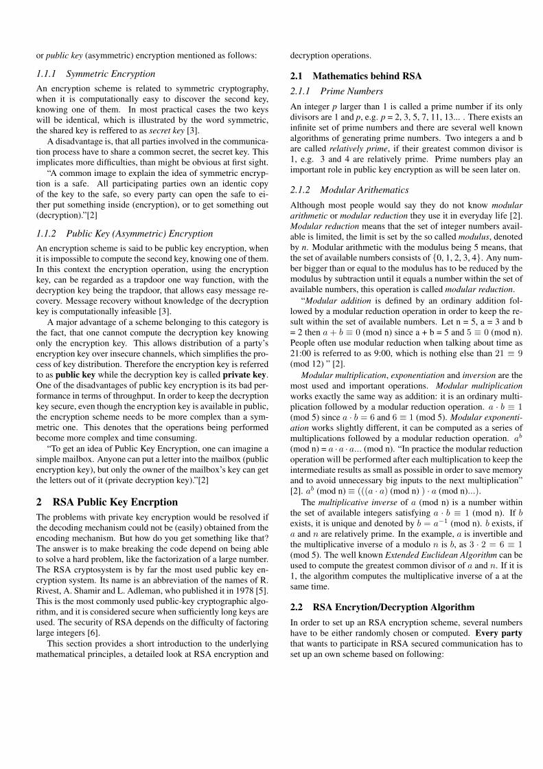
Figure 1: Miller-Rabin Primality Test [7]
3.2 Detection of primes : Miller-Rabin Primality TestThe Miller-Rabin primality test is based on the properties ofstrong pseudoprimes and relies on a series of inequalities thathold true for composite numbers. These inequalities are used tocheck if a number is composite. If some of these tests fail, thenumber is maybe prime. If many of these tests fail, we becomemore convinced that the number is prime. Therefore, by tryinga larger number of these tests, we can gain more confidence in anumbers primality, although we can never be completely sure ofit. On the other hand, if a test passes, we immediately know thatit is composite and can mark it as such [?].
Monier (1980) and Rabin (1980) showed that a compositenumber passes the test for at most of the possible bases. Thus,if N independent tests are performed on a composite number, theprobability that it passes each test is 1/4N or less.
The inequalities rely on square roots of unity. Suppose that xis a square root of 1 mod p, where p is a prime greater than 2.The following must be true: x2 ≡ 1 (mod p), which results in(x− 1)(x+ 1) = 0 (mod p). This means that x is either (1 modp) or (-1 mod p).
Now suppose that n is an odd prime. Then n-1 is an evennumber and can be written as 2s ∗ d with s and d as positiveintegers and d odd. If we choose an a in (Z/nZ)∗, then: ad ≡ 1(mod n) or ad ≡ −1 (mod n) for some 0 ≤ r ≤ s− 1.
Fermats Little Theorem says: an − 1 = 1 (mod n).If we repeatedly take square roots of an − 1, we will get ei-
ther 1 or -1. This means that if ad! ≡ 1 (mod n) or ad! ≡ −1(mod n) for some 0 ≤ r ≤ s − 1, then n is not prime. Thus, ifa is chosen and the test passes, we are sure of ns compositeness.We can call a a witness for the compositeness of n. Otherwise,a can be called a strong liar, and we can call n a strong probableprime. We can generate our a randomly in order to probabilisti-cally determine ns primality [7].
In figure 1 is the pseudocode for this algorithm [7],“We feed in odd numbers and a desired accuracy and wait
for a finish signal from the module. When the finish signal isdetected, we check the prime wire to see whether our numberis maybe prime or definitely composite. If the number is prime,we save it and if the user presses the correct key, this number isused in the RSA encryption algorithm. The number is sent to theVGA module to be viewed by the user” [7].

Figure 2: Extended Euclidean algorithm [7]
3.3 Extended Euclidean algorithm [7]The extended Euclidean algorithm is used to find d. In our im-plementation, we iterate through values of e, starting from e = 3,until the extended Euclidean algorithm indicates that the great-est common divisor of e and (p− 1)(q − 1) is 1, indicating thatthey are relatively prime, and computes a positive value for d.
In figure 2 is the pseudocode for our implementation. Unlikethe standard algorithm, we do not compute x and x − prev astheir values are not needed for our project.
This module reads values of p and q and computes (p−1) and(q−1). The module then performs the extended Euclidean algo-rithm to find the greatest common divisor of e and (p-1)(q-1) aswell as the modular inverse of e mod (p-1)(q-1). If the greatestcommon divisor is 1 (indicating that e and (p − 1)(q − 1) arerelatively prime to each other) and the modular multiplicativeinverse is positive, the module returns the values of e and themodular multiplicative inverse d to the us. Otherwise, e is incre-mented by 2 and the algorithm executed again, this is repeateduntil a value of e which results in a greatest common divisor of 1and a positive inverse is found. e will be used as the encryptionexponent and d as the decryption exponent.
3.4 VGA and Keyboard interfacingThe Complete VHDL code of the VGA and keyboard interfacingwith rest of the project modules is provided with this report. Ittook a lot of time on our part to create a fully functional and effi-cient interface. Figure 3 shows the FONT ROM and CHARAC-TER ROM, the two basic blocks for the character display mod-ule. The code for Timing Generation, etc. is provided alongwith codes for other modules. Moreover, the scanned copies ofthe calculations and notes for both Keyboard and VGA controlare also provided.
We interfaced PS/2 Keyboard afterwards. Again it was a te-dious task as We received keystrokes from the keyboard and cre-ated two registers that keep track of the current ”Write” positionof characters: one register for the character column and one reg-ister for the character row. When a new character is receivedfrom the PS/2 receiver, we write the value of the character intothe character memory. Also, increment the column register sothe next character is written in the next column position. If the
Figure 3: VGA blocks
Figure 4: Extended Euclidean algorithm [7]
character is written into the last column (79), set the column ad-dress to 0 and increment the row register (i.e., have the characterswrap around once you have finished a complete line).
3.5 Block wise implementation of modulesFigure 4 shows the general block diagram of our RSA imple-mentation. There are 4 major blocks as you can easily see in thediagram.
Figure 5 and 6 shows timing and clock constraints of the im-plementation. Figure 7 shows the project status and Device Uti-lization Summary. Figure 8 is showing the HDL Synthsis report.
4 Testing MethodologyAs described in previous section, we were as efficient as wecould in interfacing our PS/2 keyboard and the VGA monitor.So,we did not need to use any test bench. We wrote our code andchecked the outputs on the screen. Following two figures showhow we tested our random number generator. At the top corneryou can see a random number of 8 bits ASCII is being gener-
Figure 5: Timing Constraints
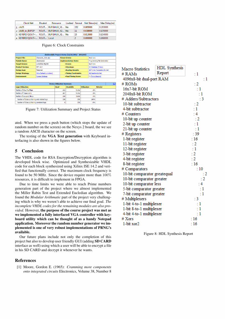
Figure 6: Clock Constraints
Figure 7: Utilization Summary and Project Status
ated. When we press a push button (which stops the update ofrandom number on the screen) on the Nexys 2 board, the we seea random ASCII character on the screen.
The testing of the VGA Text generation with Keyboard in-terfacing is also shown in the figures below.
5 ConclusionThe VHDL code for RSA Encryption/Decryption algorithm isdeveloped block wise. Optimized and Synthesizable VHDLcode for each block synthesized using Xilinx ISE 14.2 and veri-fied that functionally correct. The maximum clock frequency isfound to be 50 MHz. Since the device require more than 100%resources, it is difficult to implement in FPGA.
Due to time limits we were able to reach Prime numbersgeneration part of the project where we almost implementedthe Miller Rabin Test and Extended Eucledian algorithm. Wefound the Modular Arithmatic part of the project very challeng-ing which is why we weren’t able to achieve our final goal. Theincomplete VHDL codes for the remaining modules are also pro-vided. However, the purpose of the course project was met aswe implemented a fully interfaced VGA controller with key-board utility which can be thought of as a handy Notepadapplication. Moreover the random number generator we im-plemented is one of very robust implementations of PRNG’savailable.
Our future plans include not only the completion of thisproject but also to develop user friendly GUI (adding SD CARDinterface as well) using which a user will be able to encrypt a filein his SD CARD and decrypt it whenever he wants.
References[1] Moore, Gordon E. (1965): Cramming more components
onto integrated circuits Electronics, Volume 38, Number 8
Figure 8: HDL Synthesis Report

Figure 9: Working Figure 10: Working

Figure 11: Working Figure 12: Working

Figure 13: Working
[2] Benedikt Gierlichs: Hardware-Software Co-Design: ACase Study on an accelerated Implementation of RSA
[3] Menezes, van Oorshot, Vanstone (1997) Handbook of ap-plied cryptography, CRC Press
[4] M.K. Hani, T.S. Lin, N. Shaikh-Husin: FPGA Implemen-tation of RSA Public-Key Cryptographic Coprocessor Pro-ceedings of TENCON, vol. 3, pp. 6-11, Kuala Lumpur,Malaysia, 2000
[5] R.L. Rivest, A. Shamir, and L. Adleman (1978): A Methodfor Obtaining Digital Signatures and Public-Key Cryp-tosystems Communications of the ACM 21,2, pp. 120-126
[6] Ankit Anand, Pushkar Praveen: Implementation of RSA Al-gorithm on FPGA Centre for Development of AdvancedComputing, (CDAC) Noida, India
[7] Bruce Land: people.ece.cornell.edu
[8] : Modular Exponentiation: wikipedia, Modular Exponen-tiation
[9] : Linear feedback shift register: wikipedia, Linear feed-back shift register
[10] : Extended Euclidean algorithm: wikipedia, Extended Eu-clidean algorithm
[11] : LFSR: wikipedia, LFSR