foundry sand facts for civil engineers - cmi sand... · foundry sand facts for civil engineers...
TRANSCRIPT
Foundry Sand Facts for Civil Engineers
First Printing, May 2004 FHWA-IF-04-004

Notice: This document is disseminated under the sponsorship of the USEnvironmental Protective Agency and the Department of Transportation in theinterest of information exchange. The United States Government assumes no lia-bility for its content or the use thereof. This report does not constitute a standard,specification, or regulation. The United States Government does not endorse products or manufactures. Trade and manufactures’ names appear in this reportonly because they are considered essential to the object of this document.
1. Report No.
7. Author(s)
9. Performing Organization Name and Address
12. Sponsoring Agency Name and Address
15. Supplementary Notes
16. Abstract
17. Key Words
19. Security Classif. (of this report) 20. Security Classif. (of this page) 21. No. of Pages 22. Price
4. Title and Subtitle 5. Report Date
6. Performing Organization Code
8. Performing Organization Report No.
10. Work Unit No. (TRAIS)
11. Contract or Grant No.
13. Type of Report and Period Covered
14. Sponsoring Agency Code
18. Distribution Statement
2. Government Ascension No. 3. Recipient’s Catalog No.
Technical Report Documentation Page
Form DOT F 1700.7 (8-72) Reproduction of complete page authorizedThis form was electronically produced by Elite Federal Forms, Inc.
Foundry Sand Facts for Civil Engineers May 2004
Foundry Industry Recycling Starts Today (FIRST)
TDC Partners Ltd.417 S. St. Asaph St. Alexandria, VA 22314
FirstPO Box 333Fall River, MA 01244
Federal Highway Administration Environmental Protection AgencyWashington, DC
September 01 - September 03
Metal foundries use large amounts of sand as part of the metal casting process. Foundries successfully recycle and reuse the sand many times in a foundry. When the sand can no longer be reused in the foundry, it is removed from the foundry and is termed “foundry sand.” Foundry sand production is nearly 6 to 10 million tons annually. Like many waste products, foundry sand has beneficial applications to other industries.
The purpose of this document is to provide technical information about the potential civil engineering applications of foundry sand. This will provide a means of advancing the uses of foundry sand that are technically sound, commercially competitive and environmentally safe.
Foundry Sand, Materials, Highway Construction, Asphalt, Concrete, Flowable fills, Embankment
No restrictions. This document is available through the National Technical InformationService, Springfield VA 22161
Unclassified Unclassified 80
FHWA-IF-04-004
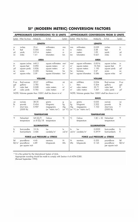
SI* (MODERN METRIC) CONVERSION FACTORS
APPROXIMATE CONVERSIONS TO SI UNITS APPROXIMATE CONVERSION FROM SI UNITS
Symbol When You Know Multiply By To Find Symbol Symbol When You Know Multiply By To Find Symbol
LENGTH
in inches 25.4 millimeters mmft feet 0.305 meters myd yards 0.914 meters mmi miles 1.61 kilometers km
AREA
in square inches 645.2 square millimeters mm2
ft2 square feet 0.093 square meters m2
yd2 square yards 0.836 square meters m2
ac acres 0.405 hectares hami2 square miles 2.59 square kilometers km2
VOLUME
fl oz fluid ounces 29.57 milliliters mLgal gallons 3.785 liters Lft3 cubic feet 0.028 cubic meters m3
yd3 cubic yards 0.765 cubic meters m3
NOTE: Volumes greater than 10001 shall be shown in m3
MASS
oz ounces 28.35 grams glb pounds 0.454 kilograms kgT short tons 0.907 megagrams Mg
(2000 lb) (or ”metric ton”) (or “t”)
TEMPERATURE0F Fahrenheit 5(F-32)/9 Celsius 0C
temperature or (F-32)/.18 temperature
ILLUMINATION
fc foot-candles 10.76 lux lxfl foot-Lamberts 3.426 candela/m2 cd/m2
FORCE and PRESSURE or STRESS
lbf poundforce 4.45 newtons Nlbf/in2 poundforce 6.89 kilopascals kPa
per square inch
LENGTH
mm millimeters 0.039 inches inm meters 3.28 feet ftm meters 1.09 yards ydkm kilometers 0.621 miles mi
AREA
mm2 square millimeters 0.0016 square inches inm2 square meters 10.764 square feet ft2
m2 square meters 1.195 square yards yd2
ha hectares 2.47 acres ackm2 square kilometers 0.386 square miles mi2
VOLUME
mL milliliters 0.034 fluid ounces fl ozL liters 0.264 gallons galm3 cubic meters 35.71 cubic feet ft3
m3 cubic meters 1.307 cubic yards yd3
NOTE: Volumes greater than 10001 shall be shown in m3
MASS
g grams 0.035 ounces ozkg kilograms 2.202 pounds lbMg megagrams 1.103 short tons T(or “t”) (or ”metric ton”) (2000 lb)
TEMPERATURE0C Celsius 1.8C = 32 Fahrenheit 0F
temperature temperature
ILLUMINATION
lx lux 0.0929 foot-candles fccd/m2 candela/m2 0.2919 foot-Lamberts fl
FORCE and PRESSURE or STRESS
N newtons 0.225 poundforce lbfkPa kilopascals 0.145 poundforce lbf/in2
per square inch
* SI is the symbol for the International System of Units. Appropriate rounding should be made to comply with Section 4 of ASTM E380.(Revised September 1993)
Forward
Metal foundries use large amounts of sand as part of the metal castingprocess. Foundries successfully recycle and reuse the sand many times in a foundry. When the sand can no longer be reused in the foundry, it isremoved from the foundry and is termed “foundry sand.” Foundry sandproduction is nearly 6 to 10 million tons annually. Like many wasteproducts, foundry sand has beneficial applications to other industries.
The purpose of this document is to provide technical information aboutthe potential civil engineering applications of foundry sand. This will provide a means of advancing the uses of foundry sand that are technicallysound, commercially competitive and environmentally safe.
This document was developed by Foundry Industry Recycling StartsToday (FIRST), in cooperation with the U. S. Department ofTransportation and the U.S. Environmental Protection Agency. The UnitedStates Government assumes no liability for its contents or use. NeitherFIRST nor the Government endorses specific products or manufacturers.This publication does not constitute a standard, specification or regulation.
Acknowledgements
This Document was prepared based on the technical references andexamples provided by a variety of sources, including the foundry industry, state departments of transportation, university researchers, and contractors. U.S. Environmental Protection Agency provided partialfinancial support of the preparation of the document.
U.S. Department of Transportation, through the Federal HighwayAdministration, supports the expanded use of recycled materials in high-way construction and provided overall technical review of the document.The authors appreciate the many agency and industry representativeswho provided information and technical comments necessary to compilethis document.
Foundry Industry Recycling Starts Today (FIRST) is a non-profit 501 (C) (3) research and education organization whose websitewww.foundryrecycling.org provides access to the technical referencesused in the preparation of this document. The American Foundry Society(AFS) is a metalcasting industry association which has sponsoredresearch on foundry sand recycling options.

Table Of Contents
Chapter 1: An Introduction to Foundry Sand . . . . . . 1
Background Information . . . . . . . . . . . . . . . . . . . . . . . . 1
Foundry Sand Uses and Availability . . . . . . . . . . . . . . . . 3
Types of Foundry Sand . . . . . . . . . . . . . . . . . . . . . . . . . 5
Foundry Sand Physical Characteristics . . . . . . . . . . . . . . 6
Foundry Sand Quality . . . . . . . . . . . . . . . . . . . . . . . . . . 9
Foundry Sand Economics . . . . . . . . . . . . . . . . . . . . . . 10
Foundry Sand Engineering Characteristics . . . . . . . . . . 11
Foundry Sand Environmental Characteristics . . . . . . . . 13
Closing . . . . . . . . . . . . . . . . . . . . . . . . . . . . . . . . . . . . 13
Chapter 2: Foundry Sand in Structural Fills and Embankments . . . . . . . . . . . . . . . . . . . . . 15
Engineering Properties for Embankments . . . . . . . . . . . 15
Construction Practices . . . . . . . . . . . . . . . . . . . . . . . . . 19
Chapter 3: Foundry Sand in Road Bases . . . . . . . . . 27
Background Information . . . . . . . . . . . . . . . . . . . . . . . 27
Purpose of the Road Base . . . . . . . . . . . . . . . . . . . . . . 28
Mix Design Evaluation . . . . . . . . . . . . . . . . . . . . . . . . 30
Control of Materials . . . . . . . . . . . . . . . . . . . . . . . . . . 33
Construction Practices . . . . . . . . . . . . . . . . . . . . . . . . . 34
Marketing Fill . . . . . . . . . . . . . . . . . . . . . . . . . . . . . . . 35
Chapter 4: Foundry Sand in Hot Mix Asphalt . . . . . 37
Introduction . . . . . . . . . . . . . . . . . . . . . . . . . . . . . . . . 37
Hot Mix Asphalt Aggregate Requirements . . . . . . . . . . 38
Case Studies . . . . . . . . . . . . . . . . . . . . . . . . . . . . . . . . 40
Concerns of the Hot Mix Industry . . . . . . . . . . . . . . . . 41
Economics . . . . . . . . . . . . . . . . . . . . . . . . . . . . . . . . . 41
Chapter 5: Foundry Sand in Flowable Fills . . . . . . . 43
Introduction . . . . . . . . . . . . . . . . . . . . . . . . . . . . . . . . 43
Mix Design and Specification Requirements . . . . . . . . . 44
Mixture Proportioning Concepts for Flowable Fills with Foundry Sand . . . . . . . . . . . . . . . . . . . . . . . . 46
Closing . . . . . . . . . . . . . . . . . . . . . . . . . . . . . . . . . . . . 48
Chapter 6: Foundry Sand in Portland Cement Concrete . . . . . . . . . . . . . . . . . . . . . . . . . . 49
Introduction . . . . . . . . . . . . . . . . . . . . . . . . . . . . . . . . 49
Mixture Design and Specification Requirements . . . . . . 49
Gradation . . . . . . . . . . . . . . . . . . . . . . . . . . . . . . . . . . 50
Effect of Material Characteristics on Foundry Sand Concrete Quality . . . . . . . . . . . . . . . . . . . . . . . . 51
Other Constituents . . . . . . . . . . . . . . . . . . . . . . . . . . . 52
Construction Practices . . . . . . . . . . . . . . . . . . . . . . . . . 53
Case Study . . . . . . . . . . . . . . . . . . . . . . . . . . . . . . . . . 53
Applications . . . . . . . . . . . . . . . . . . . . . . . . . . . . . . . . 54
Limitations . . . . . . . . . . . . . . . . . . . . . . . . . . . . . . . . . 55
Chapter 7: Foundry Sand in OtherEngineering Applications . . . . . . . . . . . . . . . . . . . . 57
Introduction . . . . . . . . . . . . . . . . . . . . . . . . . . . . . . . . 57
Foundry Sand in Portland Cement Manufacturing . . . . 57
Case Study . . . . . . . . . . . . . . . . . . . . . . . . . . . . . . . . . 59
Foundry Sand in Grouts and Mortars . . . . . . . . . . . . . 60
Foundry Sand in Agricultural/Soil Amendments . . . . . . 61
Foundry Sand to Vitrify Hazardous Materials . . . . . . . 62
Foundry Sand as a Traction Material on Snow and Ice . 62
Foundry Sand for Smelting . . . . . . . . . . . . . . . . . . . . . 62
Foundry Sand in Rock Wool Manufacturing . . . . . . . . 63
Foundry Sand in Fiberglass Manufacturing . . . . . . . . . . 63
Foundry Sand for Landfill Cover or Hydraulic Barriers . 64
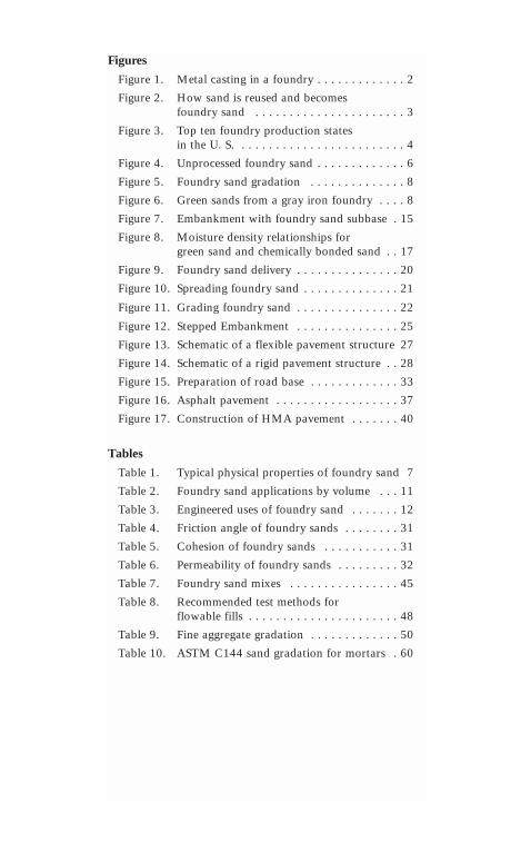
Figures
Figure 1. Metal casting in a foundry . . . . . . . . . . . . . 2
Figure 2. How sand is reused and becomes foundry sand . . . . . . . . . . . . . . . . . . . . . . 3
Figure 3. Top ten foundry production states in the U. S. . . . . . . . . . . . . . . . . . . . . . . . . 4
Figure 4. Unprocessed foundry sand . . . . . . . . . . . . . 6
Figure 5. Foundry sand gradation . . . . . . . . . . . . . . 8
Figure 6. Green sands from a gray iron foundry . . . . 8
Figure 7. Embankment with foundry sand subbase . 15
Figure 8. Moisture density relationships forgreen sand and chemically bonded sand . . 17
Figure 9. Foundry sand delivery . . . . . . . . . . . . . . . 20
Figure 10. Spreading foundry sand . . . . . . . . . . . . . . 21
Figure 11. Grading foundry sand . . . . . . . . . . . . . . . 22
Figure 12. Stepped Embankment . . . . . . . . . . . . . . . 25
Figure 13. Schematic of a flexible pavement structure 27
Figure 14. Schematic of a rigid pavement structure . . 28
Figure 15. Preparation of road base . . . . . . . . . . . . . 33
Figure 16. Asphalt pavement . . . . . . . . . . . . . . . . . . 37
Figure 17. Construction of HMA pavement . . . . . . . 40
Tables
Table 1. Typical physical properties of foundry sand 7
Table 2. Foundry sand applications by volume . . . 11
Table 3. Engineered uses of foundry sand . . . . . . . 12
Table 4. Friction angle of foundry sands . . . . . . . . 31
Table 5. Cohesion of foundry sands . . . . . . . . . . . 31
Table 6. Permeability of foundry sands . . . . . . . . . 32
Table 7. Foundry sand mixes . . . . . . . . . . . . . . . . 45
Table 8. Recommended test methods for flowable fills . . . . . . . . . . . . . . . . . . . . . . 48
Table 9. Fine aggregate gradation . . . . . . . . . . . . . 50
Table 10. ASTM C144 sand gradation for mortars . 60

1
Chapter 1:An Introduction to Foundry Sand
Background Information
What is a Foundry? A foundry is a manufactur-ing facility that produces metal castings bypouring molten metal into a preformed mold to yield the resulting hardened cast. The primarymetals cast include iron and steel from the ferrous family and aluminum, copper, brass and bronze from the nonferrous family. Thereare approximately 3,000 foundries in the U.S.
What is Foundry Sand? Foundry sand is highquality silica sand that is a byproduct from theproduction of both ferrous and nonferrous metalcastings. The physical and chemical characteris-tics of foundry sand will depend in great part on the type of casting process and the industrysector from which it originates.
Where Does it Come From? Foundries purchasehigh quality size-specific silica sands for use intheir molding and casting operations. The rawsand is normally of a higher quality than thetypical bank run or natural sands used in fillconstruction sites.
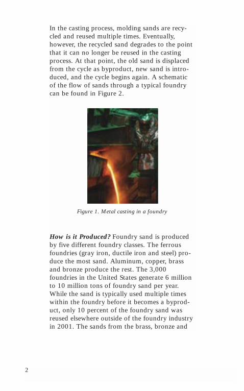
The sands form the outer shape of the mold cavity. These sands normally rely upon a smallamount of bentonite clay to act as the bindermaterial. Chemical binders are also used to create sand “cores”. Depending upon the geome-try of the casting, sands cores are inserted intothe mold cavity to form internal passages for the molten metal (Figure 1). Once the metal has solidified, the casting is separated from themolding and core sands in the shakeout process.
2
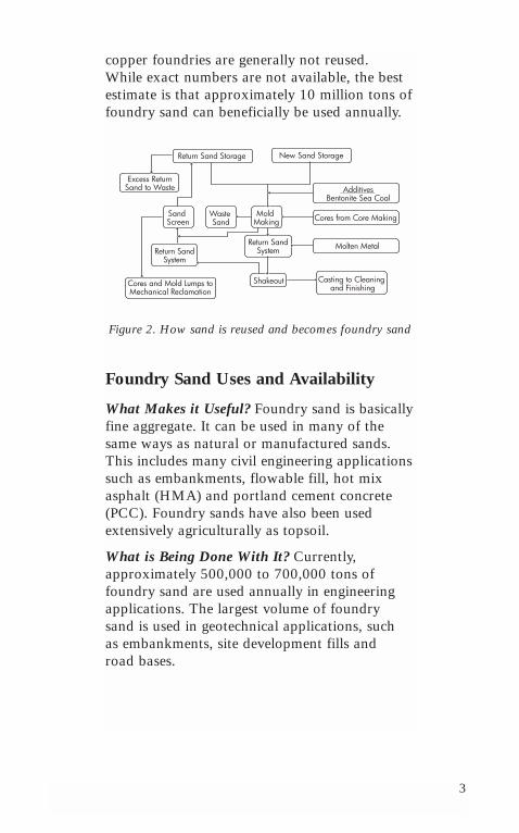
In the casting process, molding sands are recy-cled and reused multiple times. Eventually,however, the recycled sand degrades to the pointthat it can no longer be reused in the castingprocess. At that point, the old sand is displacedfrom the cycle as byproduct, new sand is intro-duced, and the cycle begins again. A schematicof the flow of sands through a typical foundrycan be found in Figure 2.
Figure 1. Metal casting in a foundry
How is it Produced? Foundry sand is producedby five different foundry classes. The ferrousfoundries (gray iron, ductile iron and steel) pro-duce the most sand. Aluminum, copper, brassand bronze produce the rest. The 3,000foundries in the United States generate 6 millionto 10 million tons of foundry sand per year.While the sand is typically used multiple timeswithin the foundry before it becomes a byprod-uct, only 10 percent of the foundry sand wasreused elsewhere outside of the foundry industryin 2001. The sands from the brass, bronze and
3
copper foundries are generally not reused. While exact numbers are not available, the bestestimate is that approximately 10 million tons offoundry sand can beneficially be used annually.
Figure 2. How sand is reused and becomes foundry sand
Foundry Sand Uses and Availability
What Makes it Useful? Foundry sand is basicallyfine aggregate. It can be used in many of thesame ways as natural or manufactured sands.This includes many civil engineering applicationssuch as embankments, flowable fill, hot mixasphalt (HMA) and portland cement concrete(PCC). Foundry sands have also been usedextensively agriculturally as topsoil.
What is Being Done With It? Currently, approximately 500,000 to 700,000 tons offoundry sand are used annually in engineeringapplications. The largest volume of foundry sand is used in geotechnical applications, such as embankments, site development fills and road bases.
Return Sand Storage New Sand Storage
Excess Return Sand to Waste
Sand Screen
Waste Sand
Mold Making
Cores and Mold Lumps to Mechanical Reclamation
Return Sand System
Return Sand System
Casting to Cleaning and Finishing
Shakeout
Molten Metal
Cores from Core Making
Additives Bentonite Sea Coal
4
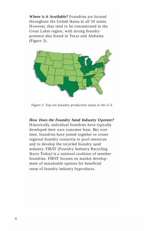
Where is it Available? Foundries are locatedthroughout the United States in all 50 states.However, they tend to be concentrated in theGreat Lakes region, with strong foundry presence also found in Texas and Alabama (Figure 3).
Figure 3. Top ten foundry production states in the U.S.
How Does the Foundry Sand Industry Operate?Historically, individual foundries have typicallydeveloped their own customer base. But overtime, foundries have joined together to createregional foundry consortia to pool resources and to develop the recycled foundry sand industry. FIRST (Foundry Industry RecyclingStarts Today) is a national coalition of memberfoundries. FIRST focuses on market develop-ment of sustainable options for beneficial reuse of foundry industry byproducts.
5
Types of Foundry Sand
How Many Types of Foundry Sand Are There?There are two basic types of foundry sand available, green sand (often referred to as molding sand) that uses clay as the binder material, and chemically bonded sand that uses polymers to bind the sand grains together.
Green sand consists of 85-95% silica, 0-12%clay, 2-10% carbonaceous additives, such as seacoal, and 2-5% water. Green sand is the most commonly used molding media byfoundries. The silica sand is the bulk mediumthat resists high temperatures while the coatingof clay binds the sand together. The water addsplasticity. The carbonaceous additives preventthe “burn-on” or fusing of sand onto the castingsurface. Green sands also contain trace chemicalssuch as MgO, K2O, and TiO2.
Chemically bonded sand consists of 93-99% silica and 1-3% chemical binder. Silica sand isthoroughly mixed with the chemicals; a catalystinitiates the reaction that cures and hardens the mass. There are various chemical binder systems used in the foundry industry. The most common chemical binder systems used are phenolic-urethanes, epoxy-resins, furfyl alcohol, and sodium silicates.
6
Foundry Sand Physical Characteristics
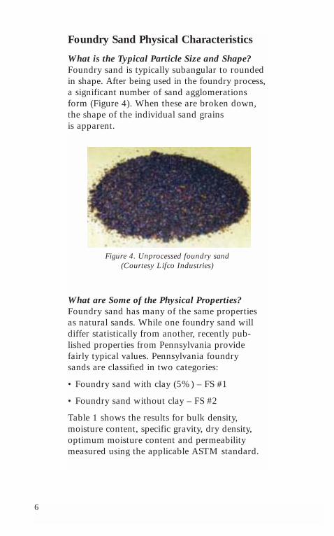
What is the Typical Particle Size and Shape?Foundry sand is typically subangular to roundedin shape. After being used in the foundry process,a significant number of sand agglomerationsform (Figure 4). When these are broken down,the shape of the individual sand grains is apparent.
Figure 4. Unprocessed foundry sand (Courtesy Lifco Industries)
What are Some of the Physical Properties?Foundry sand has many of the same propertiesas natural sands. While one foundry sand willdiffer statistically from another, recently pub-lished properties from Pennsylvania providefairly typical values. Pennsylvania foundry sands are classified in two categories:
• Foundry sand with clay (5%) – FS #1
• Foundry sand without clay – FS #2
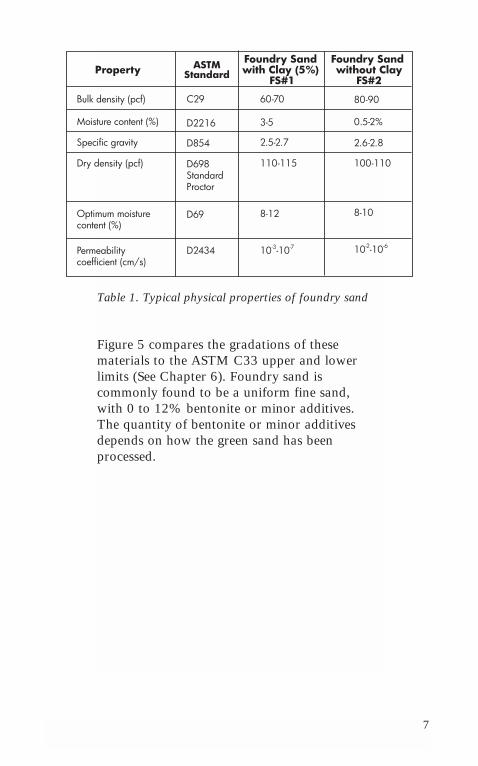
Table 1 shows the results for bulk density, moisture content, specific gravity, dry density,optimum moisture content and permeabilitymeasured using the applicable ASTM standard.
7
Table 1. Typical physical properties of foundry sand
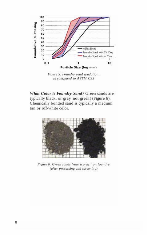
Figure 5 compares the gradations of these materials to the ASTM C33 upper and lowerlimits (See Chapter 6). Foundry sand is commonly found to be a uniform fine sand, with 0 to 12% bentonite or minor additives. The quantity of bentonite or minor additivesdepends on how the green sand has beenprocessed.
Property ASTM Standard
Bulk density (pcf)
Foundry Sand with Clay (5%)
FS#1
Moisture content (%)
Specific gravity
Dry density (pcf)
C29
D2216
D854
D698 Standard Proctor
Optimum moisture content (%)
Permeability coefficient (cm/s)
D69
D2434
60-70
3-5
2.5-2.7
110-115
8-12
10-3-10-7
80-90
0.5-2%
2.6-2.8
100-110
8-10
10-2-10-6
Foundry Sand without Clay
FS#2
8
Figure 5. Foundry sand gradation, as compared to ASTM C33
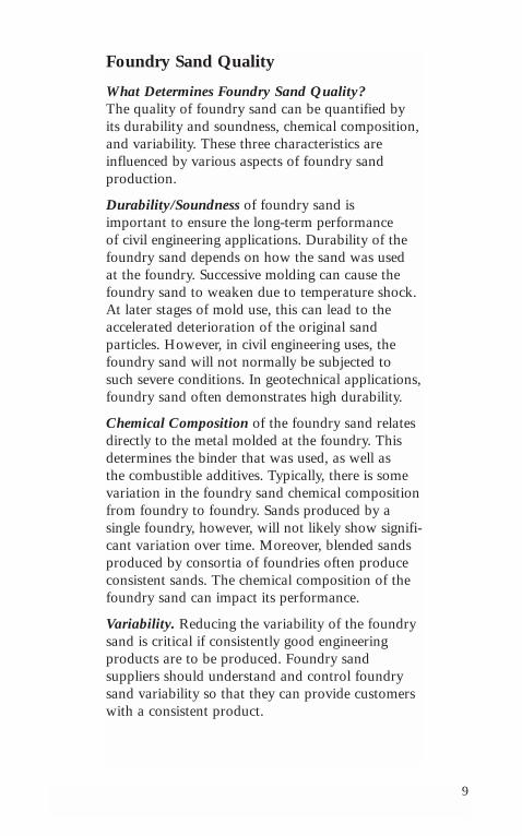
What Color is Foundry Sand? Green sands aretypically black, or gray, not green! (Figure 6).Chemically bonded sand is typically a mediumtan or off-white color.
Figure 6. Green sands from a gray iron foundry(after processing and screening)
9
Foundry Sand Quality
What Determines Foundry Sand Quality?The quality of foundry sand can be quantified byits durability and soundness, chemical composition,and variability. These three characteristics are influenced by various aspects of foundry sand production.
Durability/Soundness of foundry sand is important to ensure the long-term performance of civil engineering applications. Durability of thefoundry sand depends on how the sand was used at the foundry. Successive molding can cause thefoundry sand to weaken due to temperature shock.At later stages of mold use, this can lead to theaccelerated deterioration of the original sand particles. However, in civil engineering uses, thefoundry sand will not normally be subjected tosuch severe conditions. In geotechnical applications,foundry sand often demonstrates high durability.
Chemical Composition of the foundry sand relatesdirectly to the metal molded at the foundry. Thisdetermines the binder that was used, as well as the combustible additives. Typically, there is somevariation in the foundry sand chemical compositionfrom foundry to foundry. Sands produced by a single foundry, however, will not likely show signifi-cant variation over time. Moreover, blended sandsproduced by consortia of foundries often produceconsistent sands. The chemical composition of thefoundry sand can impact its performance.
Variability. Reducing the variability of the foundrysand is critical if consistently good engineeringproducts are to be produced. Foundry sand suppliers should understand and control foundrysand variability so that they can provide customerswith a consistent product.
10
How can I know I’m getting good quality?Methods to ensure foundry sands conform to specifications vary from State to State andsource to source. Some States require testing and approval before use. Others maintain lists of approved sources and accept project suppliers’certifications of foundry sand quality. More andmore, foundry sand generators are determiningthe engineering properties of their sands.
The degree of quality control necessary dependson experience with the specific foundry sand and its history of variability. Many purchasersrequire source testing and a certification docu-ment to accompany the shipment.
How should foundry sand be handled?Foundry sand is most often collected and stockpiled outside of the foundries, exposed tothe environment. Prior to use in an engineeringapplication, the majority of foundry sand is:
• Collected in closed trucks and transported to a central collection facility;
• Processed, screened, and sometimes crushed to reduce the size of residual core sand pieces.Other objectionable material, such as metals,are removed.
Foundry Sand Economics
The success of using foundry sand depends upon economics. The bottom line issues are cost,availability of the foundry sand and availabilityof similar natural aggregates in the region. Ifthese issues can be successfully resolved, thecompetitiveness of using foundry sand willincrease for the foundries and for the end usersof the sand. This is true of any recycled material.
11
Foundry Sand EngineeringCharacteristics
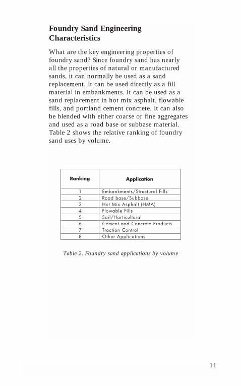
What are the key engineering properties offoundry sand? Since foundry sand has nearly all the properties of natural or manufacturedsands, it can normally be used as a sand replacement. It can be used directly as a fillmaterial in embankments. It can be used as asand replacement in hot mix asphalt, flowablefills, and portland cement concrete. It can alsobe blended with either coarse or fine aggregatesand used as a road base or subbase material.Table 2 shows the relative ranking of foundrysand uses by volume.
Table 2. Foundry sand applications by volume
Ranking Application
Embankments/Structural FillsRoad base/SubbaseHot Mix Asphalt (HMA)Flowable FillsSoil/HorticulturalCement and Concrete ProductsTraction ControlOther Applications
1 2 3 4 5 6 7 8
12
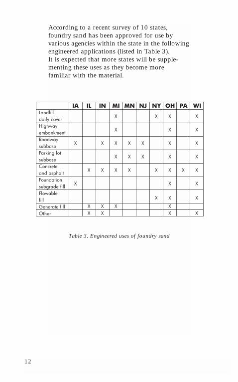
According to a recent survey of 10 states,foundry sand has been approved for use by various agencies within the state in the followingengineered applications (listed in Table 3). It is expected that more states will be supple-menting these uses as they become more familiar with the material.
Table 3. Engineered uses of foundry sand
IA IL IN MI MN NJ NY OH PA WILandfilldaily coverHighwayembankmentRoadwaysubbaseParking lotsubbaseConcreteand asphaltFoundationsubgrade fillFlowablefillGenerate fillOther
X
X
X
X
X
X
X
X
X
X
XX
X
X
X
X
X
X
X
X
X
X
X
X
X
X
X
X
XX
X
XX
X
X
X
X
X
X
X
X
13
Foundry Sand EnvironmentalCharacteristics
What about trace elements in foundry sand?Trace element concentrations present in mostclay-bonded iron and aluminum foundry sandsare similar to those found in naturally occurringsoils. The leachate from these sands may containtrace element concentrations that exceed waterquality standards; but the concentrations are nodifferent than those from other constructionmaterials such as native soils or fly ashes.Environmental regulatory agencies will guideboth the foundry sand supplier and the userthrough applicable test procedures and waterquality standards. If additional protection fromleachate is desired, mechanical methods such ascompacting and grading can prevent and furtherminimize leachate development.
In summary, foundry sand suppliers will workwith all potential users to ensure that the prod-uct meets environmental requirements for theengineering application under consideration.
Closing
Do I need to know more about this technology to use it confidently? Foundry sand can be usedto produce a quality product at a competitive costunder normal circumstances. The remaining chap-ters of this publication provide a general overviewof foundry sand use in various civil engineeringapplications. It will familiarize highway engineersand inspectors with this technology. This publica-tion is also designed to assist those individualswho have little or no previous experience usingfoundry sand or no experience in a particularapplication of foundry sand.

14
15
Chapter 2:Foundry Sand in Structural Fills andEmbankments
Engineering Properties ForEmbankments
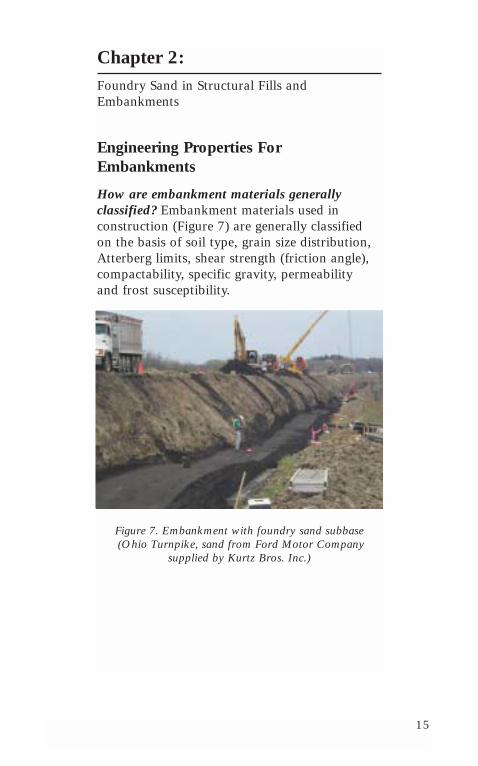
How are embankment materials generally classified? Embankment materials used in construction (Figure 7) are generally classified on the basis of soil type, grain size distribution,Atterberg limits, shear strength (friction angle),compactability, specific gravity, permeability and frost susceptibility.
Figure 7. Embankment with foundry sand subbase (Ohio Turnpike, sand from Ford Motor Company
supplied by Kurtz Bros. Inc.)
16
Soil Classification. Foundry sand would normally be classified under the Unified SoilClassification System (USCS) as SP, SM or SP-SM and under AASHTO as A-3, A-2, or A-2-4. It is a nonplastic or low plasticity sand with little or no fines. Some foundries or foundrysand suppliers will process the sand to removethe majority of silts or clays that may be present. The silt or clay content can range from 0 to 12%.
Grain Size Distribution. Foundry sand consistsof a uniform sand, with a coarse appearance.Typical gradations are provided in Chapter 1.
Atterberg Limits (Liquid and Plastic). Typicallyfoundry sand without fines is nonplastic. Theplastic behavior can depend on the clay content.For foundry sand with 6 to 10% clay, a liquidlimit LL greater than 20 and a plastic index PIgreater than 2 are typical.
Shear Strength (Friction Angle). Foundry sandshave good shear strength. For foundry sandswithout clay, the direct shear test is used tomeasure its friction angle. It ranges from 300-360,which is comparable to conventional sands. Itsshear strength is superior to silts, clays or dirtysands, showing that foundry sand is acceptablefor use as an embankment material. The triaxialshear strength test can be used to measure thedrained shear strength, friction angle and cohe-sion of foundry sands that contain clay. Atypical value of the friction angle and cohesionfor these sands is 280 and 3700 psf, respectively.But these properties can vary. Foundry sand usedon the Ohio Turnpike had a friction angle of 350
and cohesion of 6100 psf.
17
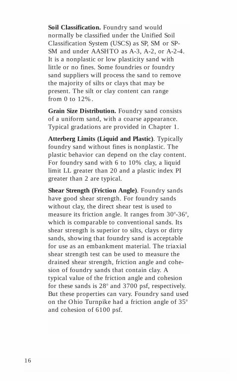
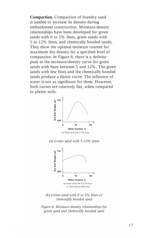
Compaction. Compaction of foundry sand is needed to increase its density during embankment construction. Moisture-densityrelationships have been developed for greensands with 0 to 5% fines, green sands with 5 to 12% fines, and chemically bonded sands.They show the optimal moisture content formaximum dry density for a specified level ofcompaction. In Figure 8, there is a definite peak in the moisture-density curve for greensands with fines between 5 and 12%. The greensands with few fines and the chemically bondedsands produce a flatter curve. The influence ofwater is not as significant for them. However,both curves are relatively flat, when compared to plastic soils.
(a) Green sand with 5-12% fines
(b) Green sand with 0 to 5% fines or chemically bonded sand
Figure 8. Moisture density relationships for green sand and chemically bonded sand
Dry
Unit
Wei
gh
t, p
cf
100
110
Water Content, %
(a) Green sand with 5-12% fines
0 10 20
(b) Green sand with 0 to 5% fines
or chemically bonded sand
Dry
Unit
Wei
gh
t, p
cf
100
110
Water Content, %
0 10 20
18
Specific Gravity. Foundry sands will normallyhave a specific gravity of 2.50 to 2.80.
Permeability. Green sands with fines less than6% and chemically bonded sands have perme-ability values in the range of 6x10⁻⁴ to 5x10⁻³
cm/sec. However, when fines such as bentoniteclay are present and greater than 6%, permeability can be lower, between 1x10⁻⁷
and 3x10⁻⁶ cm/sec.
Frost Susceptibility. Soils that are not susceptibleto frost and that do not produce heave are gravel and clean sands. Fine-grained soils aregenerally classified as frost susceptible. The finecontent of the foundry sand determines its frostsusceptibility. Foundry sand without fines canhave low to negligible frost susceptibility.
CBR (California Bearing Ratio). In foundrysand, a CBR between 11 and 30 is typical. The resistance to penetration of a 3 in2 piston in a compacted sample of foundry sand is com-pared to its resistance in a standard sample ofcompacted crushed rock. CBR is high when thewater content is dry of optimum, and then dropsafter the optimum water content is reached. TheCBR for foundry sand with fines is generallyhigher than it is for granular sands.
19
Construction Practices
General. Many contractors have found that working with foundry sand is similar to working with conventional construction materials. Foundry sand has been used effective-ly in normal embankment construction with and without permeability and leachate control.Foundry sands have also been used in conjunc-tion with geogrid systems and with reinforcedearth retaining walls that use straps or grids ashorizontal tiebacks.
Standard construction procedures can be adjust-ed to account for using foundry sand. Manyprocedures have been developed as the result ofthe experience gained using foundry sand in trialembankment and construction projects.
Stockpiling. Foundry sand can be stockpiled in a climate-controlled environment or exposed tothe elements. The foundry sand stored undercontrolled climatic conditions can be delivered to meet narrow limitations on moisture content.Conversely, the moisture content of the foundrysand stored outside will vary, depending on itslocation within the stockpile. It is recommendedthat foundry sand stockpiled outside be tested atvarious locations within the stockpile.
Site Preparation. The site should be prepared for foundry sand placement in the same way it isprepared for similar soil fill materials. It shouldbe cleared and grubbed, and the topsoil shouldbe retained for final cover. The normal precau-tions for draining the site to prevent seeps, poolsor springs from contacting the foundry sandshould be followed. Also, environmental restric-tions may require that the foundry sand beencapsulated in layers of clay.
20
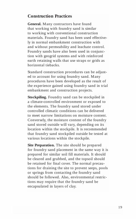
Delivery and On-Site Storage. As with any fill,foundry sand is hauled to the site in covereddump trucks (Figure 9). The water content of the foundry sand is adjusted to prevent dustingand to enhance compaction. Foundry sand canbe stockpiled on-site if the sand is kept moistand if the sand is covered.
Figure 9. Foundry sand delivery (sand supplied by Kurtz Bros., Inc., construction by Trumbull Corp.)
Spreading. Foundry sand is spread using normalconstruction equipment, such as dozers. Lifts areusually 6 to 12 inches thick. Many contractorsthen track the dozer for initial compaction.Ideally, the sand is at or near optimal moisturewhen placed; if not, water should be added.
21
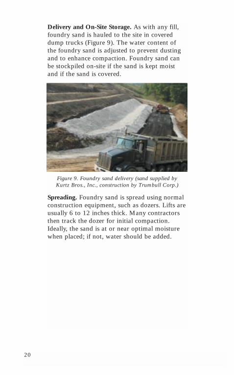
Compaction. Compaction should begin as soonas the material has been spread (Figure 10) and is at the proper moisture content. Ohio experience has shown it to be preferable to place the foundry sand as close to the optimummoisture content as possible, within 1-2%. Too dry of optimum requires significantly morecompactive effort than when the sand is properlymoisture-conditioned. However, the requiredcompaction can eventually be achieved. Foundrysands are not normally sensitive to over-rollingand can tolerate a wider range of moisture contents than natural sands.
Figure 10. Spreading foundry sand (Ohio turnpike, sand supplied by Kurtz Bros. Inc.)
Vibratory smooth drum rollers, pneumatic-tiredrollers, and vibrating plates have all been usedsuccessfully. It is important to properly screenthe foundry sand and to remove residual corepieces. In most cases cores are not a problem ifthey are less than 3 to 4” long. The compactionprocess will slow down if they are larger.
22
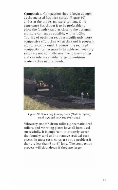
The lift thickness, the weight and speed of thecompaction equipment and the number of passesshould be determined for optimal compaction(Figure 11). Many contractors run test strips andrelate construction practices to the foundrysand’s degree of compaction. When vibratorycompaction equipment is used, lifts of 12 inchesare acceptable. In fact, thicker lifts may be pre-ferred. They provide greater confinement. If thelift is too thin, the sand may dry out too fast.Also, it will not offer enough confinement forproper compaction.
Figure 11. Grading foundry sand
In a recent project, dynamic compaction was usedsuccessfully to compact foundry sand. The mois-ture-conditioned foundry sand was placed in 10to 15 foot lifts, and then dynamically compactedby a 12 ton weight dropped from 40 to 60 feet.This height can be adjusted for the required levelof compaction and thickness of the sand layer.
23
In some foundry sand embankment construction,a foundation of coarser material such as rock orshale is placed. The foundry sand is placed ontop in uniform horizontal lifts not more than 8inches deep. It is then compacted according tonormal density specifications.
Moisture Control. As with any fill material, controlling its moisture is an important consideration in compaction. Be sure to compare hauling foundry sand that has beenmoistened to the desired water content at theplant to adding water at the site. Hauling moistfoundry sand translates to higher transportationcosts, while adding water on-site sacrifices productivity in field placement.
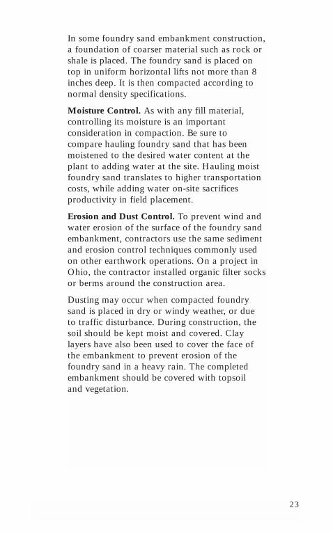
Erosion and Dust Control. To prevent wind andwater erosion of the surface of the foundry sandembankment, contractors use the same sedimentand erosion control techniques commonly usedon other earthwork operations. On a project inOhio, the contractor installed organic filter socksor berms around the construction area.
Dusting may occur when compacted foundrysand is placed in dry or windy weather, or due to traffic disturbance. During construction, thesoil should be kept moist and covered. Clay layers have also been used to cover the face ofthe embankment to prevent erosion of thefoundry sand in a heavy rain. The completedembankment should be covered with topsoil and vegetation.
24
Three Key Construction Steps. To ensure successful construction of an embankment(Figure 12), with foundry sand and its long-termperformance it is important to:
1. Assess availability. Contact the local foundrysand supplier and determine whether an ade-quate supply of foundry sand can be providedin the time frame required.
2. Investigate site conditions. As with anyembankment project, use standard geotechni-cal techniques to evaluate subsurface soil and groundwater conditions. The two mostimportant subsurface characteristics affectingembankment construction and performanceare shear strength and compressibility of thefoundation soils.
3. Evaluate the physical, engineering, andchemical properties of the foundry sand.The physical and engineering properties that will determine the behavior of a foundrysand embankment (or any embankment) are grain-size distribution, shear strength,compressibility, permeability and frost susceptibility. Laboratory tests designed fortesting soil properties apply equally well totesting foundry sands. Most foundry sand distributors can provide information on the physical, engineering and chemical composition of the foundry sand and can provide details on any possible leachate that must be considered during design and construction.
25
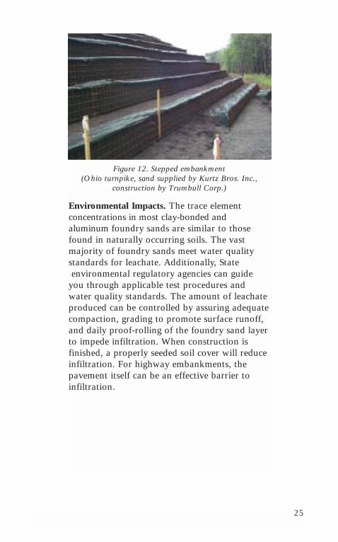
Figure 12. Stepped embankment (Ohio turnpike, sand supplied by Kurtz Bros. Inc.,
construction by Trumbull Corp.)
Environmental Impacts. The trace element concentrations in most clay-bonded and aluminum foundry sands are similar to thosefound in naturally occurring soils. The vastmajority of foundry sands meet water qualitystandards for leachate. Additionally, Stateenvironmental regulatory agencies can guide
you through applicable test procedures andwater quality standards. The amount of leachateproduced can be controlled by assuring adequatecompaction, grading to promote surface runoff,and daily proof-rolling of the foundry sand layerto impede infiltration. When construction is finished, a properly seeded soil cover will reduceinfiltration. For highway embankments, thepavement itself can be an effective barrier to infiltration.

26
27
Chapter 3:Foundry Sand in Road Bases
Background Information
What is a Road Base? A road base is a foundation layer underlying a flexible or rigidpavement and overlying a subgrade of naturalsoil or embankment fill material. It can be composed of crushed stone, crushed slag, orsome other stabilized material. It protects theunderlying soil from the detrimental effects ofenvironment and from the stresses and strainsinduced by traffic loads.
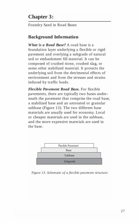
Flexible Pavement Road Base. For flexible pavements, there are typically two bases under-neath the pavement that comprise the road base,a stabilized base and an untreated or granularsubbase (Figure 13). The two different basematerials are usually used for economy. Local or cheaper materials are used in the subbase, and the more expensive materials are used in the base.
Figure 13. Schematic of a flexible pavement structure
Flexible Pavement
Base
Subbase
Subgrade
28
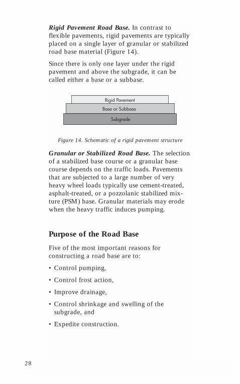
Rigid Pavement Road Base. In contrast to flexible pavements, rigid pavements are typicallyplaced on a single layer of granular or stabilizedroad base material (Figure 14).
Since there is only one layer under the rigidpavement and above the subgrade, it can becalled either a base or a subbase.
Figure 14. Schematic of a rigid pavement structure
Granular or Stabilized Road Base. The selectionof a stabilized base course or a granular basecourse depends on the traffic loads. Pavementsthat are subjected to a large number of veryheavy wheel loads typically use cement-treated,asphalt-treated, or a pozzolanic stabilized mix-ture (PSM) base. Granular materials may erodewhen the heavy traffic induces pumping.
Purpose of the Road Base
Five of the most important reasons for constructing a road base are to:
• Control pumping,
• Control frost action,
• Improve drainage,
• Control shrinkage and swelling of the subgrade, and
• Expedite construction.
Rigid Pavement
Base or Subbase
Subgrade
29
Control Pumping. For pumping to occur, threeconditions must exist simultaneously. The materialunder the concrete slab must be saturated withfree water, the material must be erodible, and frequent heavy wheel loads must pass over thepavement. These loads create large hydrodynamicpressures that transport untreated granular materi-als and even some weakly cemented materials tothe surface. This loss of fines is termed pumping.
Control Frost Action. Frost action is the combi-nation of frost heave and frost melt. Frost heavecauses the pavement to lift up, while frost meltcauses the subgrade to soften and the pavementto depress. Both lead to the break up of a pave-ment. Three factors produce frost action:
1. The soil must be frost susceptible in the depthof frost penetration. These soils generally havemore than 3% fines or are uniform sands withmore than 10% fines.
2. Water must be available.
3. Temperatures must remain below freezing for a sufficient period of time for water toflow from the water table to where the icelenses form in the road base.
Improve Drainage. A road base can raise thepavement to a desired elevation above the watertable, acting as an internal drainage system.
Control Shrinkage and Swelling of the Subgrade.If the subgrade shrinks and expands, the road basecan provide a surcharge load to reduce its move-ment. Dense graded or stabilized base coursesreduce the water entering the subgrade, and act as a waterproofing layer. Open-graded base courses serve as a drainage layer.
Expedite Construction. A road base can serve as a working platform for heavy constructionequipment.
30
Mix Design Evaluation
The road base material should be made of a mixture of crushed rock and enough fine materialto hold the rock in place and to provide good compaction. Foundry sand can be used as the finematerial in a road base. Engineering properties thatcharacterize foundry sand as a subbase material are plasticity, shear strength, compaction (moisture-density relationship), drainage and durability.
Plasticity (Shrinkage or Swelling). Green foundrysands without fines and chemically bonded sandsare typically non-plastic. However, the presence of bentonite clay increases the foundry sand’s plasticity. The plasticity index is commonly used to indicate a soil’s tendency to undergo volumechange (shrinkage or swelling). The plasticity indexis typically less than 2 for green sands with no orfew fines and chemically bonded sands, and greaterthan 2 when the clay content increases beyond 6%.
Shear Strength (Friction Angle). A soil’s shearstrength is its ability to resist deformation. Thisproperty is critical when determining a soil’s ulti-mate bearing capacity, which is the largest loadthat the road base material can support. Shearstrength depends on several material properties,such as soil cohesiveness, and the interlocking ability and packing of the particles.
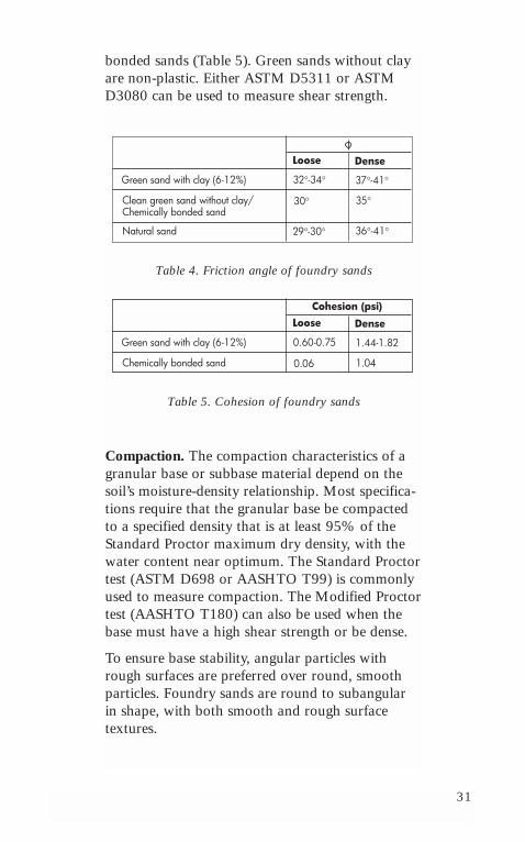
The friction angle of green sands with 6 to 12%clay is higher than it is for chemically bondedfoundry sands and green sands without clay. Thefriction angle φ in Table 4 represents the peakstrength for dense samples and the ultimatestrength for loose ones. The higher friction anglefor the green sand with clay is attributed to itsfines. Similarly, the cohesive strength of green sandswith clay is higher than it is for the chemically
31
bonded sands (Table 5). Green sands without clayare non-plastic. Either ASTM D5311 or ASTMD3080 can be used to measure shear strength.
Table 4. Friction angle of foundry sands
Table 5. Cohesion of foundry sands
Compaction. The compaction characteristics of agranular base or subbase material depend on thesoil’s moisture-density relationship. Most specifica-tions require that the granular base be compactedto a specified density that is at least 95% of theStandard Proctor maximum dry density, with thewater content near optimum. The Standard Proctortest (ASTM D698 or AASHTO T99) is commonlyused to measure compaction. The Modified Proctortest (AASHTO T180) can also be used when thebase must have a high shear strength or be dense.
To ensure base stability, angular particles withrough surfaces are preferred over round, smoothparticles. Foundry sands are round to subangular in shape, with both smooth and rough surface textures.
Green sand with clay (6-12%)
Loose Dense
Clean green sand without clay/ Chemically bonded sand
Natural sand
32°-34°
30°
29°-30°
37°-41°
35°
36°-41°
Green sand with clay (6-12%)
Loose Dense
Chemically bonded sand
0.60-0.75
0.06
1.44-1.82
1.04
Cohesion (psi)
32
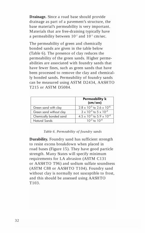
Drainage. Since a road base should providedrainage as part of a pavement’s structure, thebase material’s permeability is very important.Materials that are free-draining typically have a permeability between 10-2 and 10-3 cm/sec.
The permeability of green and chemically bonded sands are given in the table below (Table 6). The presence of clay reduces the permeability of the green sands. Higher perme-abilities are associated with foundry sands thathave fewer fines, such as green sands that havebeen processed to remove the clay and chemical-ly bonded sands. Permeability of foundry sandscan be measured using ASTM D2434, AASHTOT215 or ASTM D5084.
Table 6. Permeability of foundry sands
Durability. Foundry sand has sufficient strengthto resist excess breakdown when placed in road bases (Figure 15). They have good particlestrength. Many States will specify minimumrequirements for LA abrasion (ASTM C131 or AASHTO T96) and sodium sulfate soundness(ASTM C88 or AASHTO T104). Foundry sandwithout clay is normally not susceptible to frost,and this should be assessed using AASHTOT103.
Permeability k(cm/sec)
Green sand with clayGreen sand without clayChemically bonded sandNatural Sands
2.8 x 10⁻⁵ to 2.6 x 10⁻⁶
3 x 10⁻³ to 5 x 10⁻³
4.5 x 10⁻³ to 5.9 x 10⁻⁴
10-3 to 10-4
33
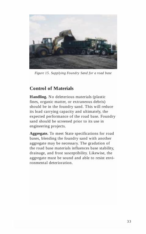
Figure 15. Supplying Foundry Sand for a road base
Control of Materials
Handling. No deleterious materials (plastic fines, organic matter, or extraneous debris)should be in the foundry sand. This will reduceits load carrying capacity and ultimately, theexpected performance of the road base. Foundrysand should be screened prior to its use in engineering projects.
Aggregate. To meet State specifications for roadbases, blending the foundry sand with anotheraggregate may be necessary. The gradation of the road base materials influences base stability,drainage, and frost susceptibility. Likewise, theaggregate must be sound and able to resist envi-ronmental deterioration.
34
Construction Practices
Blending of Materials. Aggregate used in theconstruction of road bases should be mixed andprocessed to produce a uniform blend of materi-al prior to final placement.
Construction Plants. Construction plants shouldcollect and store foundry sand until use. Becauseof the importance of the fine aggregate moisturecontent, the foundry sand should have consistentmoisture content.
Hauling. Blended mixtures can be hauled to thesite in open or covered trucks. The mix in anopen truck can dry and dust when hauled longdistances.
Spreading. The placement of road base materialshall conform to local grading ordinances andagency specifications. The typical road base is auniform layer of base material that is 6-10 inch-es thick, without any segregation. The finalthickness after compaction is 4-6 inches.
Compaction. Road base material should berolled to achieve the desired compaction andspecified density. It is important that all wastematerials be removed from the foundry sand,because it can become entangled in the com-paction equipment and delay construction.
Finishing. The final layer of road base shall befinished with equipment capable of shaping andgrading the final surface within the tolerancesspecified by the agency.
What if I can’t afford to buy specialized con-struction equipment? There is no need to! Mostplants can be readily adapted to add the foundrysand to the road base mix. For spreading, it canbe placed with a jersey spreader.
35
What advice do you have for a first time user?Using foundry sand can produce strong durableroad bases, but attention should be given to thefollowing precautions:
• Mix design evaluation. Proposed mix designsshould be evaluated for performance prior toconstruction. Good quality constituents do notalways produce a mix that will perform asdesired.
• Moisture content. Moisture must be maintained in the mix to ensure optimal compaction. The moisture may be added onsite or at the plant.
Marketing Fill
The project specific nature of the fill materialsmarket makes it difficult to quantify the totalamount of foundry sand that will be needed on a regular basis. Currently, the rates of foundrysand generation is sufficient to supply construc-tion companies and other related industries with fill material. The marketability of the sanddepends on the availability of other fill materialat or near the construction site. Transportationcosts may quickly offset the low initial costadvantage of foundry sand. Foundry sand use is more advantageous when it is stockpiled closeto the construction site.

36
37
Chapter 4:Foundry Sand in Hot Mix Asphalt
Introduction
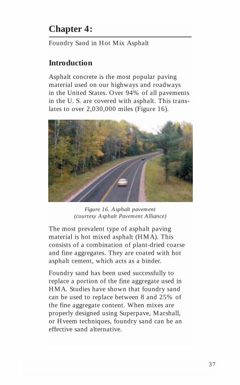
Asphalt concrete is the most popular pavingmaterial used on our highways and roadways in the United States. Over 94% of all pavementsin the U. S. are covered with asphalt. This trans-lates to over 2,030,000 miles (Figure 16).
Figure 16. Asphalt pavement (courtesy Asphalt Pavement Alliance)
The most prevalent type of asphalt paving material is hot mixed asphalt (HMA). This consists of a combination of plant-dried coarseand fine aggregates. They are coated with hotasphalt cement, which acts as a binder.
Foundry sand has been used successfully toreplace a portion of the fine aggregate used inHMA. Studies have shown that foundry sandcan be used to replace between 8 and 25% ofthe fine aggregate content. When mixes areproperly designed using Superpave, Marshall, or Hveem techniques, foundry sand can be aneffective sand alternative.
38
Hot Mix Asphalt AggregateRequirements
Hot mix asphalt production requires that allconstituent products:
• Have inherently good quality characteristics,
• Come from consistent, reputable supplysources,
• Meet all environmental requirements, and
• Are economically competitive with similarmaterials.
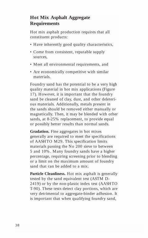
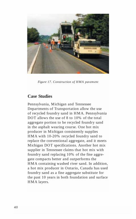
Foundry sand has the potential to be a very highquality material in hot mix applications (Figure17). However, it is important that the foundrysand be cleaned of clay, dust, and other deleteri-ous materials. Additionally, metals present in the sands should be removed either manually ormagnetically. Then, it may be blended with othersands, at 8-25% replacement, to provide equalor possibly better results than normal sands.
Gradation. Fine aggregates in hot mixes generally are required to meet the specificationsof AASHTO M29. This specification limitsmaterials passing the No 200 sieve to between 5 and 10%. Many foundry sands have a higherpercentage, requiring screening prior to blendingor a limit on the maximum amount of foundrysand that can be added to a mix.
Particle Cleanliness. Hot mix asphalt is generallytested by the sand equivalent test (ASTM D-2419) or by the non-plastic index test (AASHTOT-90). These tests detect clay portions, which arevery detrimental to aggregate-binder adhesion. Itis important that when qualifying foundry sand,
39
the clay content and organic-based additive bequantified and limited in producing an asphaltmix. For many foundry sands, the sand equiva-lent test is not applicable. According to researchdone at the University of Wisconsin at Madison,the methylene blue test (AFS 2211-00-S) is a better method for the clay content. The loss on ignition test (AASHTO T 267-86) is a goodmethod for detecting the organic based additives.
Soundness. Nearly all foundry sands meet theloss of soundness specification, AASHTO T104.
Particle Shape and Texture. Many hot mixasphalt specifications now require a fine aggregate angularity test, using AASHTO TP33.Foundry sands typically fall within the specified40-45% range.
Absorption and Stripping. Foundry sand is generally non-plastic and has low absorption.However, it is primarily silica, which in the past,has been linked to stripping. As with all silica-based hot mix asphalt mixtures, a foundry sandmix should be tested using standard strippingtests. The University of Wisconsin at Madisonhas tested foundry sand mixes for moisture damage and, depending on the clay content and the extent of organic-based additives used,foundry sands can have positive or negativeeffects on resistance to moisture damage. TheUniversity of Wisconsin at Madison is currentlydeveloping better methods to quantify clay andorganic-based additives to predict how foundrysands influence moisture damage.
40
Figure 17. Construction of HMA pavement
Case Studies
Pennsylvania, Michigan and TennesseeDepartments of Transportation allow the use of recycled foundry sand in HMA. PennsylvaniaDOT allows the use of 8 to 10% of the totalaggregate portion to be recycled foundry sand in the asphalt wearing course. One hot mix producer in Michigan consistently suppliesHMA with 10-20% recycled foundry sand toreplace the conventional aggregate, and it meetsMichigan DOT specifications. Another hot mixsupplier in Tennessee claims that hot mix withfoundry sand replacing 10% of the fine aggre-gate compacts better and outperforms the HMA containing washed river sand. In addition,a hot mix producer in Ontario, Canada has usedfoundry sand as a fine aggregate substitute forthe past 10 years in both foundation and surfaceHMA layers.
41
In Pennsylvania, 10 million tons of asphalt pavement are produced each year. Two milliontons of fine aggregate are needed. Althoughfoundry sand cannot be used to replace the totalfine aggregate quantity, it can be used to replaceup to 15%. This would allow a significantamount of foundry sand to be used each year in Pennsylvania.
Concerns of the Hot Mix Industry
To be used by the hot mix industry, foundrysand has to be a consistent product with ade-quate supply. The engineering characteristics of the foundry sand have to be relatively similarfrom batch to batch, especially in gradation, so that the resulting hot mix asphalt is also consistent. Once a proper hot mix asphalt design has been developed and calibrated with the foundry sand, it is not cost effective to change the mix design. This will result inadditional costs. If the foundry sand supplychanges during the construction season, the hot mix supplier will be responsible for any out-of-specification material, and will incur any consequent penalties.
Economics
Use of foundry sands can be cost effective for both the foundries and the HMA industry.Highway agencies and contractors could switchto the recycled material when it is geographicallyand economically competitive.

42
43
Chapter 5:Foundry Sand in Flowable Fills
Introduction
Flowable fill has several names, but each isessentially the same material:
• Controlled density fill (CDF),
• Controlled low strength material (CLSM),
• Fly ash slurry,
• Lean mix backfill,
• Unshrinkable fill, and
• Soil cement.
Flowable mixtures make up a class of engineer-ing materials having characteristics and uses thatoverlap those of a broad range of traditionalmaterials including compacted soil, soil-cement,and concrete. Flowable mixtures consist of sand,water, cement and sometimes fly ash. The mix-tures are proportioned, mixed and delivered in a very fluid consistency to facilitate placement;they provide an in-place product that is equiva-lent to a high-quality compacted soil but withoutthe expensive compaction equipment and relatedlabor. ACI defines flowable fill as a cementitiousmaterial that is in a flowable state at the time of placement and has a specified compressivestrength of 1200 psi or less at 28 days.
Flowable fills have been used as backfill forbridge structures including abutments, culverts,and trenches. It has been used for embankments,bases, and subbases. It is commonly used as bed-ding for slabs and pipes. It has also been used toeconomically fill caissons and piles, abandonedstorage tanks, sink holes, shafts and tunnels.
44
Flowable fill materials usually offer an economicadvantage over the cost of placing and compact-ing earthen backfill materials. Depending on the job conditions and costs involved, significantsavings are possible. The closer the project location to the source of the flowable fill, thegreater the potential cost savings.
Most foundry sands can be used in flowable fill mixtures. The foundry sand does not have to meet ASTM C33 gradation specificationrequirements as a concrete fine aggregate to besuitable for use in flowable fill mixes. ACI 229Rreports that foundry sand with up to 20% finesproduced successful flowable fill mixtures.Because low strength development is desirable in flowable fill, even foundry sand with organicbinders may be suitable. Foundry sand for flow-able fill can be used in a dry or moistureconditioned form.
Mix Design and SpecificationRequirements
Flowable fills typically contain portland cement,fly ash, sand and water. Foundry sand can be themajor ingredient in flowable fills. The flowablecharacter derives from its distribution of spheri-cal and irregular particle shapes and sizes. Whenmixed with enough water, the fly ash and sandsurfaces are lubricated, so that it flows.
Water requirements for mixture fluidity willdepend on the surface characteristics of all solidsin the mixture. A range of 50 to 200 gallons percubic yard would satisfy most materials combina-tions. As with most flowable fill applications, thewetter it is the better. The water acts as a meansof conveyance for the solid particles in the mix-
45
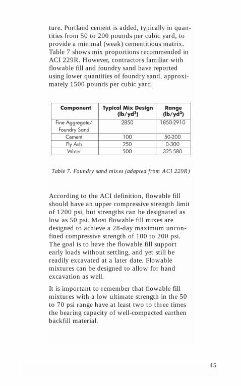
ture. Portland cement is added, typically in quan-tities from 50 to 200 pounds per cubic yard, toprovide a minimal (weak) cementitious matrix.Table 7 shows mix proportions recommended inACI 229R. However, contractors familiar withflowable fill and foundry sand have reportedusing lower quantities of foundry sand, approxi-mately 1500 pounds per cubic yard.
Table 7. Foundry sand mixes (adapted from ACI 229R)
According to the ACI definition, flowable fillshould have an upper compressive strength limitof 1200 psi, but strengths can be designated aslow as 50 psi. Most flowable fill mixes aredesigned to achieve a 28-day maximum uncon-fined compressive strength of 100 to 200 psi.The goal is to have the flowable fill supportearly loads without settling, and yet still be readily excavated at a later date. Flowable mixtures can be designed to allow for handexcavation as well.
It is important to remember that flowable fillmixtures with a low ultimate strength in the 50to 70 psi range have at least two to three timesthe bearing capacity of well-compacted earthenbackfill material.
Component Typical Mix Design(lb/yd3)
Range(lb/yd3)
Fine Aggregate/Foundry Sand
CementFly AshWater
2850
100250500
1850-2910
50-2000-300
325-580
46
Mixture Proportioning Concepts ForFlowable Fills With Foundry Sand
The following are the most important physicalcharacteristics of flowable fill mixtures:
• Compressive strength development,
• Flowability,
• Time of set, and
• Bleeding and shrinkage.
Strength Development in flowable fill mixtures is directly related to its water-to-cement ratio.Water is added to achieve a desired flowabilityor slump. Just like normal concrete mixes with a given cement content, increasing the watercontent will usually result in a decrease in compressive strength. The coarser the sand,whether natural or foundry, the higher the bear-ing capacity is of the hardened flowable fill.
Flowability is primarily a function of the watercontent and aggregate gradation. The higher thewater content and the more uniform and spheri-cal the sand, the more flowable the mixture. It is usually desirable to make the mix as flowableas possible in order to take advantage of the self-compacting qualities of the flowable fill.
47
Time of Set is directly related to the cementitiousmaterials content and type, sand content, watercontent and weather conditions at the time of placement. Within 24 hours, constructionequipment is usually expected to move acrossthe surface of the flowable fill without anyapparent damage. The time of set has beenfound to depend on the type of foundry sandincorporated into the flowable fill. Greenfoundry sands with low clay content and chemically bonded foundry sands normallyrequire less water in the mixture. The flowablefill also takes less time to harden.
Bleeding and Settlement are possible in highwater content flowable fill mixtures, since evap-oration of the bleed water often results insettlement. As with any cementitious material,plastic shrinkage cracks on the surface of the fillcan occur in high water content mixtures aswell. The main concern with plastic shrinkagecracking is that water can infiltrate at a laterdate. Flowable fill mixtures should be checkedfor settlement and plastic shrinkage.
Structural design procedures with flowable fillmaterials containing foundry sand are no differ-ent than standard geotechnical design proceduresfor conventional earth backfill materials. Thedesign procedure uses the unit weight and shearstrength of the flowable fill to calculate bearingcapacity and lateral pressure of the material forgiven site conditions.
48
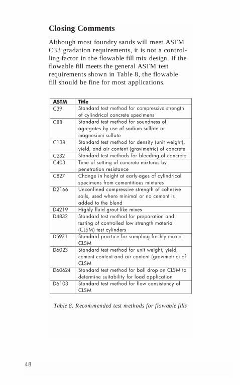
Closing Comments
Although most foundry sands will meet ASTMC33 gradation requirements, it is not a control-ling factor in the flowable fill mix design. If theflowable fill meets the general ASTM testrequirements shown in Table 8, the flowable fill should be fine for most applications.
Table 8. Recommended test methods for flowable fills
ASTMC39
C88
C138
C232C403
C827
D2166
D4219D4832
D5971
D6023
D60624
D6103
TitleStandard test method for compressive strengthof cylindrical concrete specimensStandard test method for soundness ofagregates by use of sodium sulfate ormagnesium sulfateStandard test method for density (unit weight),yield, and air content (gravimetric) of concreteStandard test methods for bleeding of concreteTime of setting of concrete mixtures bypenetration resistanceChange in height at early-ages of cylindricalspecimens from cementitious mixturesUnconfined compressive strength of cohesivesoils, used where minimal or no cement isadded to the blendHighly fluid grout-like mixesStandard test method for preparation andtesting of controlled low strength material(CLSM) test cylindersStandard practice for sampling freshly mixedCLSMStandard test method for unit weight, yield,cement content and air content (gravimetric) ofCLSMStandard test method for ball drop on CLSM todetermine suitability for load applicationStandard test method for flow consistency ofCLSM
49
Chapter 6:Foundry Sand in Portland Cement Concrete
Introduction
Portland cement concrete (PCC) is a mixture ofapproximately 25% fine aggregate, 45% coarseaggregate, 20% cement and 10% water. Foundrysand can be used beneficially in concrete produc-tion as a fine aggregate replacement.
Mixture Design and SpecificationRequirements
Aggregates are classified based on particle size.Fine aggregates consist of natural sand orcrushed stone with particle diameters smallerthan 3/8 inch. Coarse aggregates are gravel orcrushed stone with particle diameters rangingbetween 3/8 inch and 2 inches.
The selection of aggregate used in concrete is ofgreat importance. Aggregate properties stronglyinfluence the concrete’s freshly mixed and hard-ened properties. Aggregate must be:
• Clean and free of objectionable materials,including organic material, clay and deleteriouscontaminants, which can affect bonding of the cement paste to the aggregate,
• Strong, hard and durable, and
• Uniformly graded.
50
Gradation
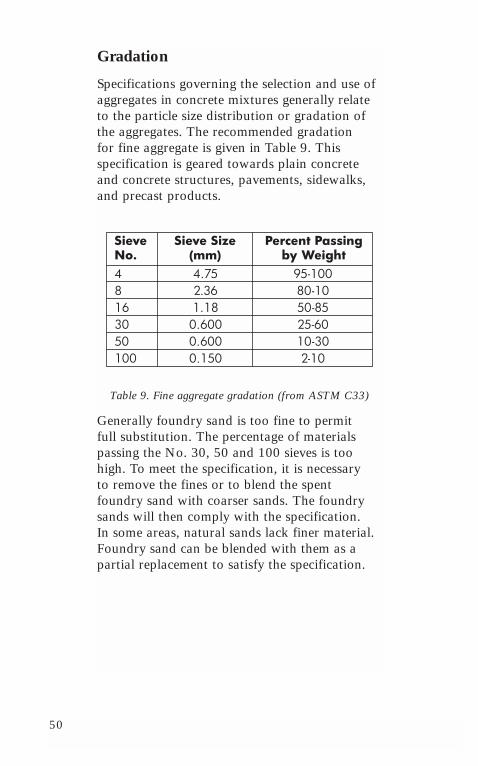
Specifications governing the selection and use ofaggregates in concrete mixtures generally relateto the particle size distribution or gradation ofthe aggregates. The recommended gradation for fine aggregate is given in Table 9. This specification is geared towards plain concreteand concrete structures, pavements, sidewalks,and precast products.
Table 9. Fine aggregate gradation (from ASTM C33)
Generally foundry sand is too fine to permit full substitution. The percentage of materialspassing the No. 30, 50 and 100 sieves is toohigh. To meet the specification, it is necessary to remove the fines or to blend the spentfoundry sand with coarser sands. The foundrysands will then comply with the specification. In some areas, natural sands lack finer material.Foundry sand can be blended with them as apartial replacement to satisfy the specification.
SieveNo.
Sieve Size(mm)
Percent Passingby Weight
48163050100
4.752.361.180.6000.6000.150
95-10080-1050-8525-6010-302-10
51
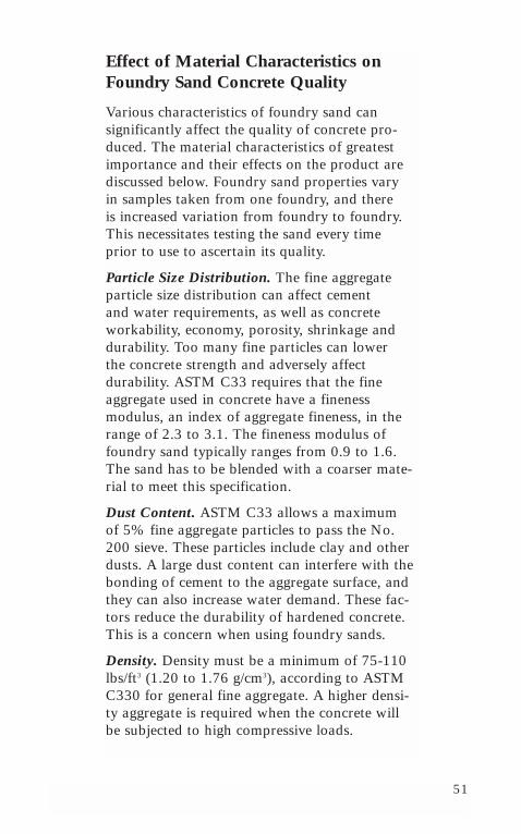
Effect of Material Characteristics onFoundry Sand Concrete Quality
Various characteristics of foundry sand can significantly affect the quality of concrete pro-duced. The material characteristics of greatestimportance and their effects on the product arediscussed below. Foundry sand properties vary in samples taken from one foundry, and there is increased variation from foundry to foundry.This necessitates testing the sand every timeprior to use to ascertain its quality.
Particle Size Distribution. The fine aggregate particle size distribution can affect cement and water requirements, as well as concreteworkability, economy, porosity, shrinkage anddurability. Too many fine particles can lower the concrete strength and adversely affect durability. ASTM C33 requires that the fineaggregate used in concrete have a fineness modulus, an index of aggregate fineness, in therange of 2.3 to 3.1. The fineness modulus offoundry sand typically ranges from 0.9 to 1.6.The sand has to be blended with a coarser mate-rial to meet this specification.
Dust Content. ASTM C33 allows a maximum of 5% fine aggregate particles to pass the No.200 sieve. These particles include clay and otherdusts. A large dust content can interfere with thebonding of cement to the aggregate surface, andthey can also increase water demand. These fac-tors reduce the durability of hardened concrete.This is a concern when using foundry sands.
Density. Density must be a minimum of 75-110lbs/ft3 (1.20 to 1.76 g/cm3), according to ASTMC330 for general fine aggregate. A higher densi-ty aggregate is required when the concrete willbe subjected to high compressive loads.
52
Organics Content/Deleterious MaterialsContent. According to ASTM C33, the maxi-mum amount of clay lumps and friable particlesallowed is 3%. Organic content is restrictedbecause it interferes with hydration of the cementand its subsequent strength. The organic contentof aggregate can be measured by a color test.
Grain Shape. Round particles need less waterand cement to coat their surface, and they pro-duce a mixture that is more workable.Angularity increases water demand and cementcontent to maintain a workable mix. Foundrysand particles are typically angular to rounded.
Specific Gravity. Although specific gravity doesnot directly relate to concrete quality, it can beused as a quality control indicator. The specificgravity of foundry sand varies from 2.5 to 2.8,depending on the source. This compares veryfavorably to natural sands.
Other Constituents
Coarse Aggregate. Coarse aggregates used in the concrete mixture should be appropriatelysampled and tested to ensure good quality. Some aggregates of marginal quality have been observed to adversely affect the matrix of hardened concrete.
Cement. Foundry sand can be used in combina-tion with all types of cementitious materials.
Chemical Admixtures. In general, foundry sandcan be used with any concrete containing chemi-cal admixtures. Retarders and water reducers are compatible with most foundry sands. Aswith natural sands, any organic material in the foundry sand may affect the dosage and
53
effectiveness of air entraining agents. Trial mix-tures should always be examined for anypotential compatibility problems.
Construction Practices
General Considerations. Foundry sand must beprocessed prior to reuse, i.e. screened, crushed,and magnetic particles should be separated. Thiswill remove waste and deleterious materials,such as tramp metal and core pieces, preventingtechnical problems at the mix plant.
Plant Operations. A separate bin should bereserved for the foundry sand at the plant, as isdone for fly ash. Foundry sand can be handledin typical aggregate holding bins. It is importantto keep the bins clean and the foundry sand dryto help eliminate any bulking problems at thegate opening.
Case Study
Laboratory Use of Foundry Sand in Concrete.An American Foundry Society (AFS) study inIllinois investigated foundry sand as a substitutefor fine aggregate in concrete. When foundrysands without fines replaced a portion of the fineaggregate, the concrete produced had compres-sive strengths, tensile strengths and modulus ofelasticity values comparable to mixtures com-posed of natural sand.
On the other hand, when green foundry sandsthat had not been processed replaced 33% of the fine aggregate, the resulting concrete com-pressive strengths at 28 days were between 2600psi and 4000 psi. These low strength concretes
54
can be used in applications not requiring struc-tural grade concrete, such as buried applicationslike sewer pipe or below grade concrete. Thedecrease in concrete compressive strength, aswell as in tensile strength and modulus of elasticity, were attributed to too many fines and organic materials (clay and dust) in thefoundry sand.
Likewise, foundry sand has been used to makepaving blocks and bricks. For these applications,foundry sand replaced 35% of the fine aggre-gate. If the fineness modulus was not exceeded,the concrete product was acceptable providedthey met the ASTM specifications for minimumcompressive strength, absorption, and bulk den-sity. It is recommended that proper testing beperformed to establish the appropriate limits onfoundry sand addition prior to using it in com-mercially produced products.
Applications
Concrete can be used for cast-in-place or pre-cast products such as pipes, ornamental concrete units, load bearing structural units (i.e.,beams, girders, etc.), utility structures and con-crete blocks. The ultimate use, shape, and size of the product will govern the type and grada-tion of the aggregate required in the concretemixture. For example, the final dimensions ofthe precast block will determine the maximumaggregate size. For this reason, when marketingspent foundry sand to precast producers or to a ready mix plant, the particle size distributionrequirements should be requested ahead of time.
55
When the required concrete compressive strengthis between 50 psi and 2500 psi, a 50% fineaggregate substitution with foundry sand hasbeen successful. As with regular concrete, trialmixtures should always be tested prior to pro-duction for any potential compatibility problems.
Limitations
Foundry sand is black. In some concretes, this may cause the finished concrete to have agrayish/black tint, which may not be desirable. A 15% fine aggregate replacement with foundrysand produces a minimal color change. Also, the foundry must be able to meet the quantityrequirements of the precast manufacturer.

56
57
Chapter 7:Foundry Sand in Other Engineering Applications
Introduction
Other engineering applications of foundry sandwill be presented in this chapter. They includeusing foundry sand in:
• Portland cement manufacturing,
• Mortars,
• Agricultural / soil amendments,
• Traction material on snow and ice,
• Vitrification of hazardous materials,
• Smelting,
• Rock wool manufacturing,
• Fiberglass manufacturing, and
• Landfill cover or hydraulic barriers.
Foundry Sand in Portland CementManufacturing
Portland cement reacts chemically with waterwhen hydrating, causing it to set and to harden.When mixed with fine and coarse aggregate,concrete is formed. There are several specifica-tions for portland cement, as designated byASTM C150 and ASTM C1157.
Production of Portland Cement. Portland cement is manufactured using materials with theappropriate proportions of calcium oxide, silica,alumina, and iron oxide. These ingredients arefound in natural rock, like shale, dolomite, and
58
limestone. It is the chemistry of the foundry sand as a silica source that is more important in cement production than is its grain size orshape. The requirements that must be met forfoundry sand to be used in portland cement production are:
• Its silica content equals or exceeds 80%,
• It is a low alkali material,
• A large quantity of sand is available, and
• It has uniform particle sizes.
Foundry sand may be one of the highest qualitysources of silica available to the cement industry.The major chemical constituents of raw portlandcement available in foundry sand include silicaand alumina and iron oxides. By using foundrysands to replace virgin sands, the quantity ofmined virgin sands can be reduced.
Blended Cements. Blended hydraulic cements are of particular interest in the beneficial use offoundry sand, since these cements are producedby blending together two or more types of finematerials. Historically, blended cements haveincluded portions of blast furnace slag or fly ash.
Foundry Sand Acceptance by Portland CementManufacturers. The cement manufacturer has to evaluate the foundry sand to confirm its compatibility with other raw materials. In addition, cement producers need a chemicaloxide analysis, TCLP results, annual volume and a sample. The chemical oxide analysisshows the amount of silica contained in thesand, while the TCLP shows whether or not the sand is hazardous. Also, because limestone,silica and clay are all common materials, thecement manufacturer has to be willing to usefoundry sand.
59
Limitations. Factors that may limit foundry sanduse in portland cement manufacturing involvelimits on the quantity of foundry sand availableand cost issues. Cement manufacturers requiresignificant quantities of silica, 10,000–40,000tons annually for a plant. It is unlikely that asingle foundry can provide that much sand. The sand from several foundries should bepooled at a community storage site to meet thedemands of a single cement plant.
Cement manufacturers will pay nominal fees tofoundries for the use of their spent sand, but willconsider it waste disposal. Additional chargesmay be levied for handling fees and shipping.However, there is potential for cost savings.
Case Studies
Laboratory Study of Foundry Sand in Cement.The American Foundry Society (AFS) in Illinoisstudied using green sand from a gray ironfoundry in portland cement manufacture. First, a chemical analysis of the sand was performed to see if it met AASHTO specifications. Based onthe chemical content, the foundry sand appearedto be an attractive alternative to raw material forcement kiln feed. Four mixtures were designedusing 0%, 4.45%, 8.9% and 13.36% of foundrysand. The chemical characteristics of the result-ing clinkers showed little difference betweenthose made with and without foundry sand. The cement produced with the foundry sand met all the relevant chemical specifications. Theproperties of the cement, namely set time andcompressive strength, were not affected by thepresence of foundry sand. There was even aslight increase in compressive strength.
60
Commercial Study by Frazer & Jones. In January1994, a green sand manufacturer (Frazer & Jones)in up-state New York shipped 15,000 tons offoundry sand to a cement manufacturer in Ontario,Canada. It was used successfully as a replacementfor excavated silica materials in the manufacture oflow-alkali portland cement. The finished productwas a high quality portland cement.
Foundry Sand in Grouts and Mortars
Mortars primarily consist of sand, cement andother additives, and are used in masonry construc-tion. Its primary uses are to joint and seal concretemasonry units, to strengthen masonry structures by bonding with steel reinforcing, and to providearchitectural quality. Approximately one cubic footof sand is used to make one cubic foot of mortar.The cement paste occupies the space between thesand particles and makes it workable.
Sand used in masonry mortar mixes is generallyspecified based on grading. ASTM C144 recom-mends the following gradation (Table 10). Sandsthat are deficient in fines make a coarse mix and ones that have too many fines produce a weak mortar.
Table 10. ASTM C144 sand gradation for mortars
Sieve No. Sieve Size(mm)
Percent Passingby Weight
48163050100200
4.752.361.180.6000.3000.1500.075
10095-10070-8540-7520-4010-250-10
61
A well-suited aggregate will fall into the middle of this range. Adequate gradation reduces mortarsegregation and bleeding and improves mortarwater retention and workability. Foundry sand isgenerally finer than the ASTM gradation require-ments, but it can be blended with coarser sands to meet the specification.
In addition to aggregate gradation, the aggregateshould be clean and free from wastes, and alsohave a consistent moisture content. Likewise, thecolor of the foundry sand can impart a dark tint to the mortar, so it should be deemed acceptableprior to its use in architectural projects.
Foundry Sand in Agricultural/SoilAmendments
Foundry sand can be used as an additive in topsoiland compost materials. It is ideal for topsoil manu-facture because of its uniformity, consistency, anddark color. Since a high sand content is required intopsoil, it is an essential ingredient. In composting,foundry sand reduces the formation of clumps andprevents the mix from compacting. This allows airto circulate through the material and to stimulatedecomposition. Ohio nurseries have been blendingfoundry sands with soils and compost for use onornamentals. Kurtz Bros. of Ohio has also used itsuccessfully as golf green topdressing. For theseapplications, the presence of clay is beneficial, sinceit promotes the retention of nutrients.
Regulatory issues for foundry sand use in agricultur-al applications vary from State to State on a case-by-case basis.
62
Foundry Sand to Vitrify HazardousMaterials
Because of foundry sand’s high silica content, it is an ideal candidate to encapsulate, vitrify orneutralize hazardous materials. Preliminary testsshow that this is a feasible option.
Foundry Sand as a Traction Material on Snow and Ice
Another possible use of foundry sand is as ananti-skid material on roads covered with snowand ice. Particularly its angular particlesimprove traction on highways in the winter.Likewise, its black color (ex. green sand) willhold the heat longer and will melt the ice faster.To be used as an anti-skid material, the foundrysand must meet each State’s requirements.Typically, foundry sand is too fine to complywith anti-skid regulations, but when mixed witha coarser material, it does comply. Trial mixesshould be formulated and evaluated prior touse. In addition, the foundry sand should be free from glass, metals, or other substances thatcould be harmful to cars and vehicles.
Foundry Sand for Smelting
Another potential use for foundry sand is as a raw material in zinc and copper smelting.Foundry sand can be used in place of virginsand. Guidelines for using silica sands in zincand copper smelting are that the sand should be relatively pure silica (minimum 99.0%), have a maximum particle size of 2 mm and abulk phenol content of less than 2 mg/kg (ppm).
63
The foundry should demonstrate to the smeltingplant that the foundry sand meets these criteriaand will produce quality zinc and copper.
Case Study. A smelter in California has beenusing recycled foundry sand for some time. Allof the foundry sands used in area brass and steelfoundries were deemed acceptable due to theirhigh silica content.
Foundry Sand in in Rock WoolManufacturing
Rock wool fibers are commonly used to reinforce other materials, such as building material insulation, and are similar to fiberglass.Foundry sand can serve as a source of silica inthe rock wool production process. They are produced by combining blast furnace slag withsilica or alumina in a cupola furnace and thenfiberizing the molten material. To be used in production, the foundry sand has to be pre-treated and formed into briquettes.
Foundry Sand in FiberglassManufacturing
Foundry sand can be used in the manufacture of fiberglass. Fiberglass is produced by meltingsilica sand and straining it through a platinumsieve with microscopic holes, thereby formingthe desired glass fibers. Manufacturers of fiber-glass, such as Owens-Corning and CertainTeedCorporation, have specifications for silica con-tent and particle size distribution, so to be usedin this application, the foundry sand has to havethe needed properties.
64
Foundry Sand for Landfill Cover orHydraulic Barriers
Foundry sand has been used for some time as a daily cover soil on municipal waste landfillsand as a landfill liner. Foundry sand containingclay (> 6%) and the following Atterberg limits(liquid limit greater than 20 and plastic indexgreater than 3) has a low permeability. It is anideal material for final or top cover. It is alsoexpected to be resistant to permeation by brines and leachates in the short term.
Each State may have different requirementsplaced on landfill materials and foundry sandusage should be decided on a case-by-case basis.

65
Notes:

66
Notes:

67
Notes:

68
Notes:

69
Notes:
