forno per pizza - pizza-oven - four pour pizza - … · forno per pizza - pizza-oven - four pour...
TRANSCRIPT
Mod. HENERGO HV/45 E-1
FORNO PER PIZZA - PIZZA-OVEN - FOUR POUR PIZZA -PIZZA-OFEN - HORNO PARA PIZZA
MANUALE D'USO E MANUTENZIONE OPERATING AND SERVICE MANUAL MODE D'EMPLOI ET D'ENTRETIEN BEDIENUNGS- UND WARTUNGSHANDBUCH MANUAL DE USO Y MANTENIMIENTO
...................................................................... ...............................................................
Tel. : ................... - ..............................
Fax. : .................. - ..............................
...................................................................... ...............................................................
Tel. : ................... - ..............................
Fax. : .................. - ..............................
OEM - ALI SpAViale Lombardia, 33
46012 BOZZOLO (MN) ItaliaTel. 0376- 910511 - Fax 0376 - 920754
Model - Modèle - Modell - Modelo
Serial number - Numéro d' immatriculation - Kenn-Nummer - Número de matrícula
Delivery date - Date di livraison - Lieferdatum - Fecha de entrega
SEDI o AGENTI - OFFICES OR AGENTS - SIÈGES OU AGENTSNIEDERLASSUNGEN oder VERTRETER - SEDES y AGENTES
COSTRUTTORE - MANUFACTURER - PRODUCTEUR - HERSTELLER - FABRICANTE
Modello. ............................................................................................................................
Numero di matricola. .......................................................................................................
Data di consegna. .......................................................................................................... .
Realizzato per OEM - ALI SpA da DUESSE Service - Samarate (VA) - www.duesse.it
Istruzioni originaliTranslation of original instructionsTraduction des instructions d'origineÜbersetzung der OriginalanleitungTraducción de las instrucciones originales
3
DICHIARAZIONE CE DI CONFORMITA' DECLARATION OF CONFORMITY - DECLARATION CE DE CONFORMITE
CE-KONFORMITÄTSERKLÄRUNG - DECLARACIÓN CE DE CONFORMIDAD'
OEM - ALI SpAViale Lombardia, 33
46012 BOZZOLO (MN) ItaliaTel. 0376- 910511 - Fax 0376 - 920754
per tramite del Dott. Giussani Antonio Massimo, in qualità di preposto della sede secondariathrough Mr. Giussani Antonio Massimo, acting as managing director
par l’intermédiaire Dr. Giussani Antonio Massimo , en qualité de prèvôt de la siége secondairebzw. der gesetzliche vertreter Hr. Giussani Antonio Massimo als zweitsitzleiter
a través del Dr. Giussani Antonio Massimo, en su calidad de encargado de la sede secundaria,
Dichiara che il modello - It is hereby declared that modelDéclare que le modèle - erklärt, daß die Maschine Modell
Declara que el modelo
HV/45 EIT è conforme alle disposizioni legislative che traspongono le direttive e successivi emendamenti: EN complies with the law provisions that transpose the directives and relevant amendments: FR est conforme aux dispositions législatives qui transposent les directives et amendements successifs: DE den gesetzlichen Richtlinienbestimmungen und nachfolgenden Änderungen: ES es conforme a las disposiciones legislativas que transponen las directivas y sucesivas enmiendas:
2006/42 - 2006/95/CE - 2004/108 - DPR 24/7/1996 n° 459 IT e inoltre dichiara che sono state applicate le seguenti norme armonizzateEN it is also hereby declared that the following harmonized provisions have been applied FR et en plus elle déclare que les normes suivantes ont été appliquées DE sowie folgenden harmonisierten Normen: ES y declara además que han sido aplicadas las siguientes normas armonizadas
EN 55014-1:2006; EN 55014-2:1997+A1:2001 + A2:2008; EN 61000-3-2:2006;EN 61000-3-3:1995+A1:2001+A1:2001+A2/ISI:2005; EN 61000-3-11:2000
EN 61000-3-12:2005; EN 62233:2008EN 60335-2-36:2000+A1:2004+A2:2008(EN 60335-1:2002+A1:2004+A11:2004+A12:2006+A2:2006)
Il fascicolo tecnico è costituito dal Sig. REBIZZI FRANCESCO in qualità di Responsabile Uffi cio Tecnico.
Firma del legale rappresentante - Signature of the legal representativeSignature du représentant légal - Unterschrift des Rechtsvertreters
Firma del rapresentante legal
(Massimo Giussani)
.............................................................
4
Frontespizio - Frontispiece - FrontispieceTitelseite - Frontespizio
INDICE GENERALEGENERAL INDEX - INDEX GENERAL
ALLGEMEINES INHALTSVERZEICHNIS - ÍNDICE GENERAL
Italiano ................................Pag.IT - 1English .............................. Pag.EN - 1Français .............................Pag.FR - 1Deutsch ...........................Seite.DE - 1Español ..............................Pag.ES - 1
G45
Norme ed avvertenze generali
IT - 1
ITALIANO
CAPITOLO ........................................................1Capitolo per il tecnico e l'operatore1.1 AVVERTENZE GENERALI ................................... Pag. IT-31.2 RIFERIMENTI NORMATIVI .................................. Pag. IT-41.3 DESCRIZIONE SIMBOLOGIE .............................. Pag. IT-41.4 COMPOSIZIONE DELLA MACCHINA .................. Pag. IT-41.5 PREDISPOSIZIONI A CARICO DELL'ACQUIRENTE ............................................. Pag. IT-51.6 OPERAZIONI DI EMERGENZA IN CASO DI INCENDIO ........................................ Pag. IT-51.7 RISCHIO DI ESPLOSIONE ................................... Pag. IT-51.8 LIVELLO DI PRESSIONE ACUSTICA ................. Pag. IT-5
CAPITOLO ........................................................2Capitolo per il tecnico- DIMENSIONI DI INGOMBRO .................................... Pag. IT-62.1 CARATTERISTICHE TECNICHE ....................... Pag. IT-72.2 TRASPORTO ........................................................ Pag. IT-8 2.2.a Spedizione .................................................... Pag. IT-8 2.2.b Sollevamento imballo ................................... Pag. IT-8 2.2.c Stoccaggio .................................................... Pag. IT-82.3 CONTROLLO AL RICEVIMENTO ......................... Pag. IT-92.4 DISIMBALLO ......................................................... Pag. IT-92.5 IDENTIFICAZIONE COMPONENTI .................... Pag. IT-102.6 IDENTIFICAZIONE DELLA MACCHINA ............. Pag. IT-10
CAPITOLO ........................................................3Capitolo per il tecnico3.1 SOLLEVAMENTO MACCHINA ........................... Pag. IT-113.2 ASSEMBLAGGIO COMPONENTI .................... Pag. IT-113.3 COLLEGAMENTO ELETTRICO ........................ Pag. IT-12 3.3.a Collegamento elettrico forno ...................... Pag. IT-12 3.3.b Collegamento equipotenziale ..................... Pag. IT-133.4 POSIZIONAMENTO FORNO .............................. Pag. IT-133.5 PRIMA ACCENSIONE ........................................ Pag. IT-133.6 INVERSIONE DEL SENSO DI ROTAZIONE NASTRO ....................................... Pag. IT-143.7 INSTALLAZIONE PIANO DI APPOGGIO OPZIONALE ........................................................ Pag. IT-143.8 INSTALLAZIONE RULLIERA OPZIONALE ........ Pag. IT-14
CAPITOLO ........................................................4Capitolo per il tecnico e l'operatore4.1 USO PREVISTO ................................................. Pag. IT-154.2 USO SCORRETTO ............................................ Pag. IT-154.3 TARGHETTE DI SICUREZZE ............................. Pag. IT-154.4 SICUREZZE ........................................................ Pag. IT-164.5 ZONE OPERATORE ........................................... Pag. IT-164.6 ZONE A PERICOLO RESIDUO .......................... Pag. IT-164.7 ZONE PERICOLOSE .......................................... Pag. IT-16
CAPITOLO ........................................................5Capitolo per il tecnico e l'operatore5.1 PANNELLO COMANDI ....................................... Pag. IT-175.2 FUNZIONAMENTO ............................................. Pag. IT-185.3 MODIFICA IMPOSTAZIONI ................................ Pag. IT-195.4 REGOLAZIONE ALTEZZA BOCCA .................... Pag. IT-195.5 ALLARMI DURANTE IL FUNZIONAMENTO ...... Pag. IT-20 5.5.a Allarme sonda temperatura dnneggiata o scheggiata ............................................. Pag. IT-20 5.5.b Allarme motore nastro ................................ Pag. IT-20 5.5.c Allarme sovratemperatura forno ................. Pag. IT-205.6 SPEGNIMENTO .................................................. Pag. IT-205.7 MALFUNZIONAMENTI,CAUSE E RIMEDI ......... Pag. IT-21
CAPITOLO ........................................................6Capitolo per il tecnico e l'operatore6.1 MANUTENZIONE ORDINARIA E PROGRAMMATA ............................................... Pag. IT-22 6.1.a Generalità ................................................. Pag. IT-22 6.1.b Interventi di manutenzione ordianaria ...... Pag. IT-22 6.1.b - a Pulizia esterna .................................... Pag. IT-22 6.1.b - b Pulizia interna forno ........................... Pag. IT-22 6.1.c Interventi di manutenzione programmata . Pag. IT-24 6.1.c - a Ogni 2 anni ......................................... Pag. IT-24 6.1.d Interventi di manutenzione secondo necessità .................................................. Pag. IT-24 6.1.d - a Tensionamento nastro ........................ Pag. IT-24
CAPITOLO ........................................................7Capitolo per il tecnico7.1 SMONTAGGIO DELLA MACCHINA ................... Pag. IT-257.2 DEMOLIZIONE DELLA MACCHINA ................... Pag. IT-257.3 SMALTIMENTO DELLE SOSTANZE NOCIVE ... Pag. IT-25
SCHEMA ELETTRICO 220 MONOFASE .................. Pag. IT-26SCHEMA ELETTRICO 230 TRIFASE ........................ Pag. IT-27SCHEMA ELETTRICO 400 TRIFASE ........................ Pag. IT-28
LEGENDA ................................................................. Pag. IT-29

G45
Norme ed avvertenze generali
IT - 3
1.1 - AVVERTENZE GENERALI
- Prima di procedere alla messa in funzione della macchina l’operatore dovrà aver letto con cura il presente manuale ed avere acquisito una profonda conoscenza delle specifi che tecniche e dei comandi.
- È consigliabile che l’operatore segua un periodo di addestramento per quanto concerne l’uso della mac-china.
- Prima d’installare la macchina, controllare che l’area adibita sia compatibile con le dimensioni d’ingombro e il peso della stessa.
- In caso d’installazione o rimozione di parti della macchina, usare solo mezzi di sollevamento e movimentazione ade-guati al peso ed alle caratteristiche geometriche del pezzo da sollevare/movimentare.
- Non permettere a personale non autorizzato e qualifi cato di mettere in funzione, regolare, o riparare la macchina.
Far riferimento inoltre a questo manuale per le operazioni necessarie.
- Le parti meccaniche ed i componenti elettrici situati all’interno della macchina sono protetti da pannelli interamente chiusi mediante viti.
- Prima di procedere alla pulizia e/o alla manutenzione della macchina, e prima di rimuovere qualsiasi protezione, ac-certarsi che l’interruttore generale sia in posizione di “OFF” (O) , in modo da togliere l’alimentazione elettrica alla macchina durante l’intervento dell’operatore.
- L’impianto di alimentazione elettrica, dell’acquirente, deve essere provvisto di un sistema di sgancio automatico a monte dell’interruttore generale della macchina e di un idoneo impianto di messa a terra che risponda a tutti i requisiti delle norme per la prevenzione degli infortuni.
- Nel caso si debba intervenire sull’interruttore generale o nelle sue vicinanze, togliere tensione alla linea a cui é allacciato l’interruttore generale.
- Tutti i controlli e le operazioni di manutenzione che richiedono la rimozione delle protezioni di sicurezza vengono effettuati sotto la completa responsabilità dell’utente.
Si raccomanda pertanto di far eseguire queste opera-zioni esclusivamente a personale tecnico specializzato ed autorizzato.
- Controllare che tutti i dispositivi antinfortunistici di sicurezza (barriere, protezioni, carter, microinterruttori, ecc.) non siano stati manomessi e che siano perfettamente funzionanti. In caso contrario provvedere alla loro sistemazione.
- Non rimuovere i dispositivi di sicurezza.
- Onde evitare rischi personali, utilizzare solo attrezzi idonei e conformi ai regolamenti nazionali di sicurezza.
- Non manomettere per nessun motivo l’impianto elettrico, quello pneumatico o qualunque altro meccanismo.
- Non lasciare la macchina in funzione incustodita.
- Indossare capi di abbigliamento approvati ai fi ni antinfortu-nistici come dalle norme in vigore.
- In caso di operazioni o riparazioni da effettuarsi in posizioni non raggiungibili direttamente dal suolo, utilizzare scale o mezzi di sollevamento che siano sicure e conformi ai regolamenti nazionali di sicurezza.
- In caso di riparazioni vicino o sotto la macchina, assicurarsi che:
• non ci siano organi che possano entrare in funzione; e/o particolari instabili per loro natura posizionati sulla macchina
o nelle sue vicinanze:
- Non utilizzare le mani al posto di adeguati utensili per operare sulla macchina.
- Non utilizzare le mani od altri oggetti per arrestare parti in movimento.
- Non usare fi ammiferi, accendini, o fi amme libere nelle vicinanze della macchina.
- PRESTARE LA MASSIMA ATTENZIONE ALLE TARGHET-TE DI AVVERTENZA PRESENTI SULLA MACCHINA OGNI VOLTA CI SI APPRESTI AD OPERARE SULLA STESSA O NELLE SUE VICINANZE.
- E’ fatto obbligo all’utente di mantenere tutte le targhe segna-letiche leggibili, cambiandone, se necessario, la posizione, al fi ne di garantire la completa visibilità all’operatore.
- E’ inoltre fatto obbligo all’utente di sostituire tutte le targhe segnaletiche che per qualunque motivo si siano deteriorate o non chiaramente leggibili, richiedendo quelle nuove al Servizio Ricambi.
- É assolutamente vietato eseguire riparazioni quando la macchina è in funzione.
- In caso di malfunzionamenti della macchina o danni ai componenti contattare il responsabile autorizzato alla ma-nutenzione, senza procedere arbitrariamente ad interventi di riparazione.
- E’ fatto assoluto divieto a chiunque di utilizzare la mac-china per usi diversi da quelli espressamente previsti e documentati.
L’uso della macchina dovrà avvenire sempre nei modi, tempi e luoghi previsti dalle norme di buona tecnica, secondo la direttiva macchine CEE 89/392 e nel rispetto delle norme riguardanti la salute e sicurezza dei lavoratori indicate nelle leggi vigenti nel paese di utilizzo o, se mancanti, secondo la direttiva CEE 89/391.
- La ditta costruttrice declina ogni responsabilità per eventuali incidenti o danni a persone o cose insorgenti dalla mancata osservanza sia delle norme relative alla sicurezza che delle istruzioni riportate in questo ma-nuale.
Capitolo 1
G45
Norme ed avvertenze generali
IT - 4
- QUESTE NORME DI SICUREZZA INTEGRANO O COMPENSANO LE NORME DI SICUREZZA IN VIGORE LOCALMENTE.
- Non eseguire MAI riparazioni affrettate o di fortuna che potrebbero compromettere il buon funzionamento della macchina e la sicurezza dell’operatore.
- IN CASO DI DUBBIO RICHIEDERE SEMPRE L’INTER-VENTO DI PERSONALE SPECIALIZZATO.
- QUALSIASI MANOMISSIONE, ELETTRICO/ELETTRO-NICO O MECCANICO DELLA MACCHINA DA PARTE DELL’UTENTE E SE L'USO DELLA MACCHINA É FATTO CON NEGLIGENZA, SOLLEVA LA DITTA COSTRUTTRI-CE DA OGNI RESPONSABILITÀ E RENDE L’UTENTE STESSO UNICO RESPONSABILE VERSO GLI ORGANI COMPETENTI PER LA PREVENZIONE DEGLI INFORTU-NI.
1.2 - RIFERIMENTI NORMATIVI- La macchina e i suoi dispositivi di sicurezza sono
stati costruiti in conformità alle norme indicate nella dichiarazione di conformità.
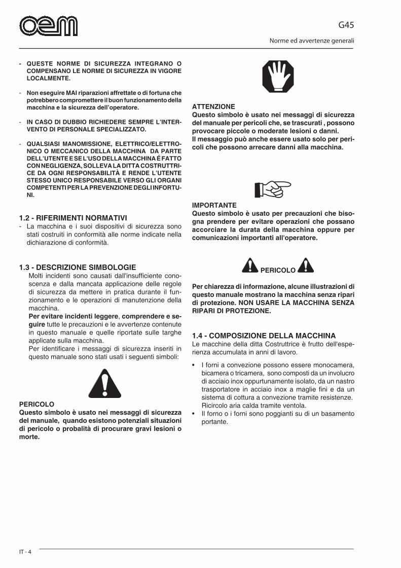
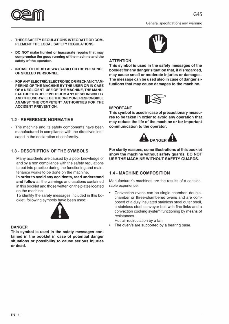
1.3 - DESCRIZIONE SIMBOLOGIEMolti incidenti sono causati dall'insuffi ciente cono-scenza e dalla mancata applicazione delle regole di sicurezza da mettere in pratica durante il fun-zionamento e le operazioni di manutenzione della macchina.Per evitare incidenti leggere, comprendere e se-guire tutte le precauzioni e le avvertenze contenute in questo manuale e quelle riportate sulle targhe applicate sulla macchina.Per identifi care i messaggi di sicurezza inseriti in questo manuale sono stati usati i seguenti simboli:
PERICOLOQuesto simbolo è usato nei messaggi di sicurezza del manuale, quando esistono potenziali situazioni di pericolo o probalità di procurare gravi lesioni o morte.
ATTENZIONEQuesto simbolo è usato nei messaggi di sicurezza del manuale per pericoli che, se trascurati , possono provocare piccole o moderate lesioni o danni.Il messaggio può anche essere usato solo per peri-coli che possono arrecare danni alla macchina.
IMPORTANTEQuesto simbolo è usato per precauzioni che biso-gna prendere per evitare operazioni che possano accorciare la durata della macchina oppure per comunicazioni importanti all'operatore.
PERICOLO
Per chiarezza di informazione, alcune illustrazioni di questo manuale mostrano la macchina senza ripari di protezione. NON USARE LA MACCHINA SENZA RIPARI DI PROTEZIONE.
1.4 - COMPOSIZIONE DELLA MACCHINALe macchine della ditta Costruttrice è frutto dell'espe-rienza accumulata in anni di lavoro.
• I forni a convezione possono essere monocamera, bicamera o tricamera, sono composti da un involucro di acciaio inox oppurtunamente isolato, da un nastro trasportatore in acciaio inox a maglie fi ni e da un sistema di cottura a convezione tramite resistenze.
Ricircolo aria calda tramite ventola.• Il forno o i forni sono poggianti su di un basamento
portante.
G45
Norme ed avvertenze generali
IT - 5
1.5 - PREDISPOSIZIONI A CARICO DELL’ACQUIRENTE
a) Predisposizione luogo installazione.• L'acquirente deve predisporre una superfi cie di ap-
poggio per la macchina come indicato nel capitolo installazione.
b) Predisposizione elettrica.• L’impianto elettrico di alimentazione deve essere con-
forme a quanto indicato dalle vigenti norme nazionali del luogo e dotato di una effi ciente messa a terra.
• Posizionare sulla linea di alimentazione, a monte della macchina, un dispositivo onnipolare di sezio-namento.
• I cavi elettrici di alimentazione devono essere dimensionati in funzione alla massima cor-rente richiesta dalla macchina in modo che la caduta di tensione totale, a pieno carico, risulti inferiore al 2%.
c) Gestione del neutro• L'apparecchiatura è dotata di neutro e quindi è stato
predisposto un'apposito morsetto identifi cato secondo le specifi che normative.
1.6 - OPERAZIONI DI EMERGENZA IN CASO DI INCENDIO
a) In caso di incendio togliere tensione alla macchina disinserendo l'interruttore generale.
b) Spegnere l'incendio utilizzando idonei estintori.
PERICOLO
Con la macchina in tensione è assolutamente vietato cercare di spegnere l'incendio con acqua.
1.7 - RISCHIO DI ESPLOSIONE• La macchina non è adatta per essere utilizzata in am-
bienti con rischio di esplosione.
1.8 - LIVELLO DI PRESSIONE ACUSTICAI forni modello GHIBLI G45 sono stati costruiti al fi ne di mantenere il livello di pressione acustica continuo equi-valente ponderato A(dB) al di sotto del limite massimo consentito di 70dB.
G45
Dati tecnici - Trasporto e disimballo
IT - 6
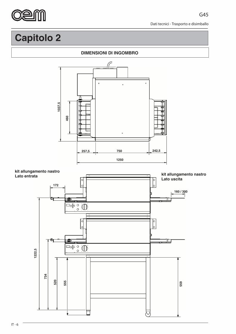
1037
,5
460
750
1250
257,5 242,5
1222
,5
734
520
555 655
160 / 300
172
DIMENSIONI DI INGOMBRO
Capitolo 2
kit allungamento nastroLato entrata kit allungamento nastro
Lato uscita

G45
Dati tecnici - Trasporto e disimballo
IT - 7
2.1 - CARATTERISTICHE TECNICHE
Modello G45/1 G45/2 G45/3
Collegamento elettrico 230V 1 ~ 230V 1 ~ 230V 1 ~ 230V 3 ~ 230V 3 ~ 230V 3 ~ 400V 3 ~ 400V 3 ~ 400V 3 ~ 50Hz 50Hz 50Hz
Potenza - kW/h - kW-max 12,5 25 37,5
Sezione cavo 3 x 10 mm2 3 x 10 mm2 3 x 10 mm2
230 V - 1 230 V - 1 230 V - 1
4 x 2,5 mm2 4 x 2,5 mm2 4 x 2,5 mm2
230 V - 3 230 V - 3 230 V - 3
5 x 2,5 mm2 5 x 2,5 mm2 5 x 2,5 mm2
400 V - 3 400 V - 3 400 V - 3
Peso netto 129 kg 258 kg 387 kg
Umidità relativa 10 ÷ 80 %
Mod. Resistenza Resistenza Potenza cielo platea Max.
Kw
G45/1 3x2000 W 3x2000 W 12
G45/2 6x2000 W 6x2000 W 24
G45/3 9x2000 W 9x2000 W 36
G45
Dati tecnici - Trasporto e disimballo
IT - 8
a b
c d
FIG. 2
FIG. 1FIG. 1
FIG. 2
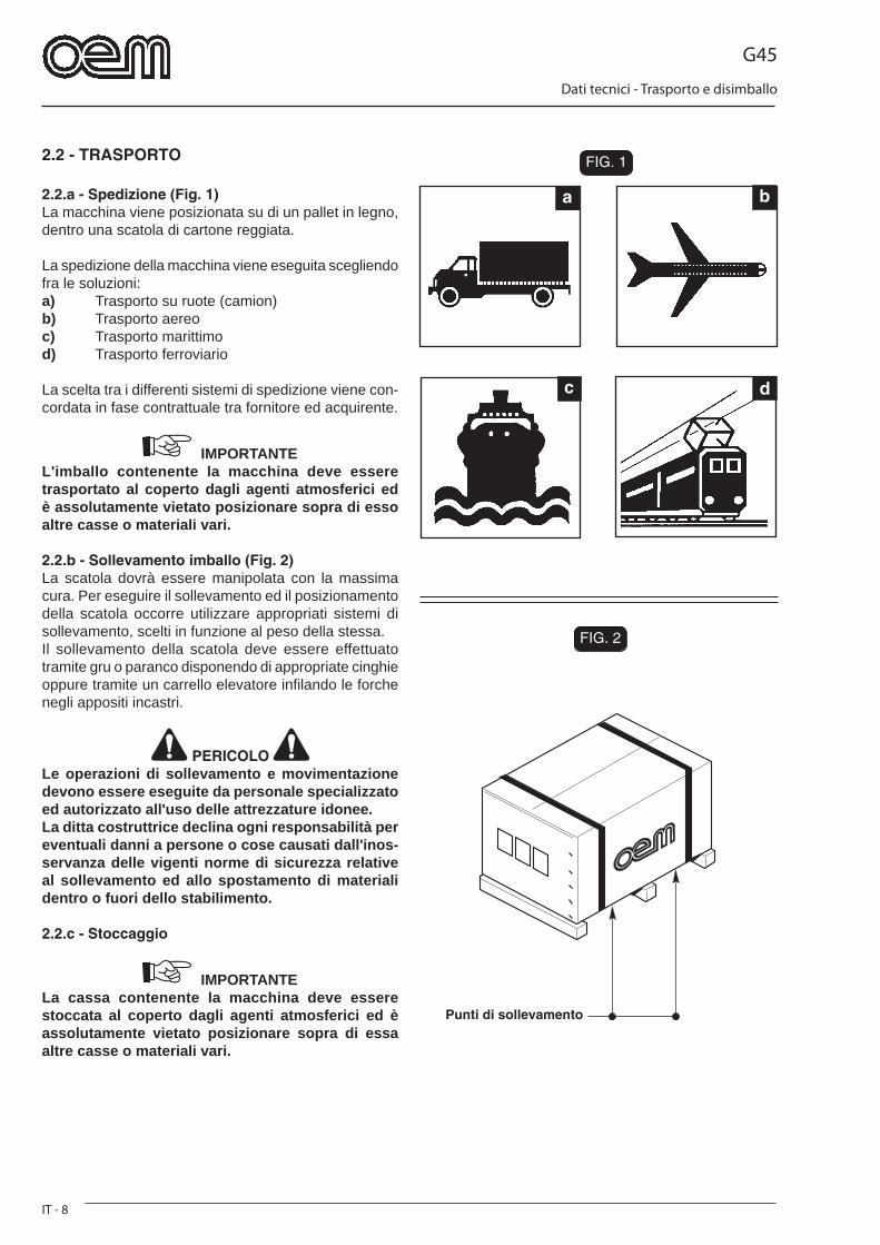
2.2 - TRASPORTO
2.2.a - Spedizione (Fig. 1)La macchina viene posizionata su di un pallet in legno, dentro una scatola di cartone reggiata.
La spedizione della macchina viene eseguita scegliendo fra le soluzioni:a) Trasporto su ruote (camion)b) Trasporto aereoc) Trasporto marittimod) Trasporto ferroviario
La scelta tra i differenti sistemi di spedizione viene con-cordata in fase contrattuale tra fornitore ed acquirente.
IMPORTANTEL'imballo contenente la macchina deve essere trasportato al coperto dagli agenti atmosferici ed è assolutamente vietato posizionare sopra di esso altre casse o materiali vari.
2.2.b - Sollevamento imballo (Fig. 2)La scatola dovrà essere manipolata con la massima cura. Per eseguire il sollevamento ed il posizionamento della scatola occorre utilizzare appropriati sistemi di sollevamento, scelti in funzione al peso della stessa.Il sollevamento della scatola deve essere effettuato tramite gru o paranco disponendo di appropriate cinghie oppure tramite un carrello elevatore infi lando le forche negli appositi incastri.
PERICOLO Le operazioni di sollevamento e movimentazione devono essere eseguite da personale specializzato ed autorizzato all'uso delle attrezzature idonee.La ditta costruttrice declina ogni responsabilità per eventuali danni a persone o cose causati dall'inos-servanza delle vigenti norme di sicurezza relative al sollevamento ed allo spostamento di materiali dentro o fuori dello stabilimento.
2.2.c - Stoccaggio
IMPORTANTELa cassa contenente la macchina deve essere stoccata al coperto dagli agenti atmosferici ed è assolutamente vietato posizionare sopra di essa altre casse o materiali vari.
Punti di sollevamento
G45
Dati tecnici - Trasporto e disimballo
IT - 9
FIG. 3
1
1
2
3
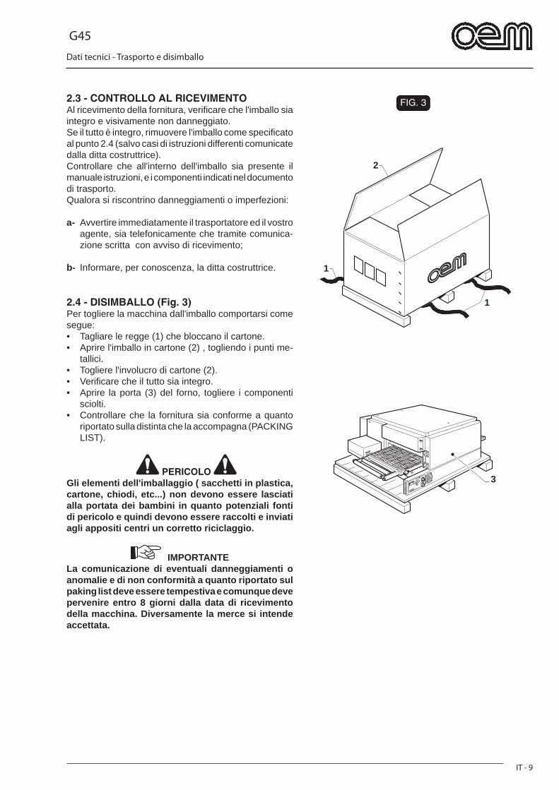
2.3 - CONTROLLO AL RICEVIMENTOAl ricevimento della fornitura, verifi care che l'imballo sia integro e visivamente non danneggiato.Se il tutto è integro, rimuovere l'imballo come specifi cato al punto 2.4 (salvo casi di istruzioni differenti comunicate dalla ditta costruttrice).Controllare che all'interno dell'imballo sia presente il manuale istruzioni, e i componenti indicati nel documento di trasporto. Qualora si riscontrino danneggiamenti o imperfezioni:
a- Avvertire immediatamente il trasportatore ed il vostro agente, sia telefonicamente che tramite comunica-zione scritta con avviso di ricevimento;
b- Informare, per conoscenza, la ditta costruttrice.
2.4 - DISIMBALLO (Fig. 3)Per togliere la macchina dall'imballo comportarsi come segue:• Tagliare le regge (1) che bloccano il cartone.• Aprire l'imballo in cartone (2) , togliendo i punti me-
tallici.• Togliere l'involucro di cartone (2).• Verifi care che il tutto sia integro.• Aprire la porta (3) del forno, togliere i componenti
sciolti.• Controllare che la fornitura sia conforme a quanto
riportato sulla distinta che la accompagna (PACKING LIST).
PERICOLO Gli elementi dell'imballaggio ( sacchetti in plastica, cartone, chiodi, etc...) non devono essere lasciati alla portata dei bambini in quanto potenziali fonti di pericolo e quindi devono essere raccolti e inviati agli appositi centri un corretto riciclaggio.
IMPORTANTELa comunicazione di eventuali danneggiamenti o anomalie e di non conformità a quanto riportato sul paking list deve essere tempestiva e comunque deve pervenire entro 8 giorni dalla data di ricevimento della macchina. Diversamente la merce si intende accettata.

G45
Dati tecnici - Trasporto e disimballo
IT - 10
FIG. 4
7
5
55
4
6
1
2
3
2.5 - IDENTIFICAZIONE COMPONENTI (Fig. 4)1. Forno 1 - G45/12. Forno 2 - G45/23. Forno 3 - G45/34. Supporto5. Ruote (Optional)6. Pannello comandi7. Targa dati
2.6 - IDENTIFICAZIONE DELLA MACCHINA (Fig. 4)
Il numero di matricola ed i dati per l'identifi cazione della macchina sono punzonati su una targhetta (9) fi ssata sul basamento della macchina.
IMPORTANTE Nelle eventuali richieste di assistenza tecnica o nelle ordinazioni delle parti di ricambio, citare sempre il numero di matricola della macchina.
G45
Installazione e collegamenti
IT - 11
FIG. 2
FIG. 1
4
22
1 1
13
1
3
2
4
6 5
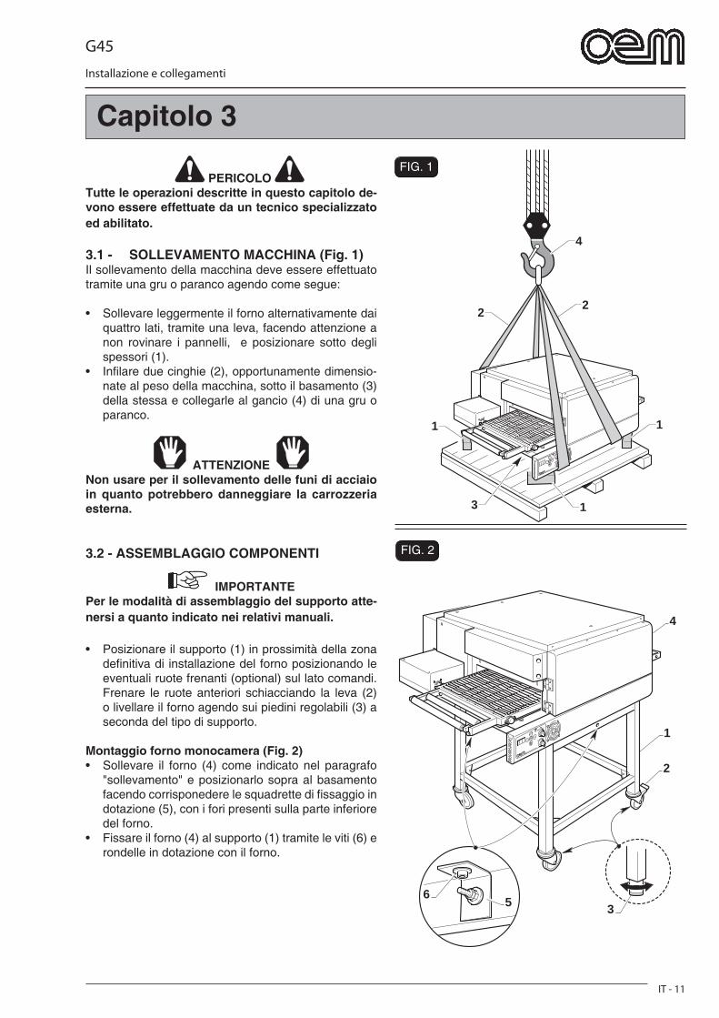
PERICOLO Tutte le operazioni descritte in questo capitolo de-vono essere effettuate da un tecnico specializzato ed abilitato.
3.1 - SOLLEVAMENTO MACCHINA (Fig. 1)Il sollevamento della macchina deve essere effettuato tramite una gru o paranco agendo come segue:
• Sollevare leggermente il forno alternativamente dai quattro lati, tramite una leva, facendo attenzione a non rovinare i pannelli, e posizionare sotto degli spessori (1).
• Infi lare due cinghie (2), opportunamente dimensio-nate al peso della macchina, sotto il basamento (3) della stessa e collegarle al gancio (4) di una gru o paranco.
ATTENZIONE Non usare per il sollevamento delle funi di acciaio in quanto potrebbero danneggiare la carrozzeria esterna.
3.2 - ASSEMBLAGGIO COMPONENTI
IMPORTANTEPer le modalità di assemblaggio del supporto atte-nersi a quanto indicato nei relativi manuali.
• Posizionare il supporto (1) in prossimità della zona defi nitiva di installazione del forno posizionando le eventuali ruote frenanti (optional) sul lato comandi. Frenare le ruote anteriori schiacciando la leva (2) o livellare il forno agendo sui piedini regolabili (3) a seconda del tipo di supporto.
Montaggio forno monocamera (Fig. 2)• Sollevare il forno (4) come indicato nel paragrafo
"sollevamento" e posizionarlo sopra al basamento facendo corrisponedere le squadrette di fi ssaggio in dotazione (5), con i fori presenti sulla parte inferiore del forno.
• Fissare il forno (4) al supporto (1) tramite le viti (6) e rondelle in dotazione con il forno.
Capitolo 3
G45
Installazione e collegamenti
IT - 12
FIG. 3
FIG. 41
2
T
F3 N3
F2F1
1
2
3
4
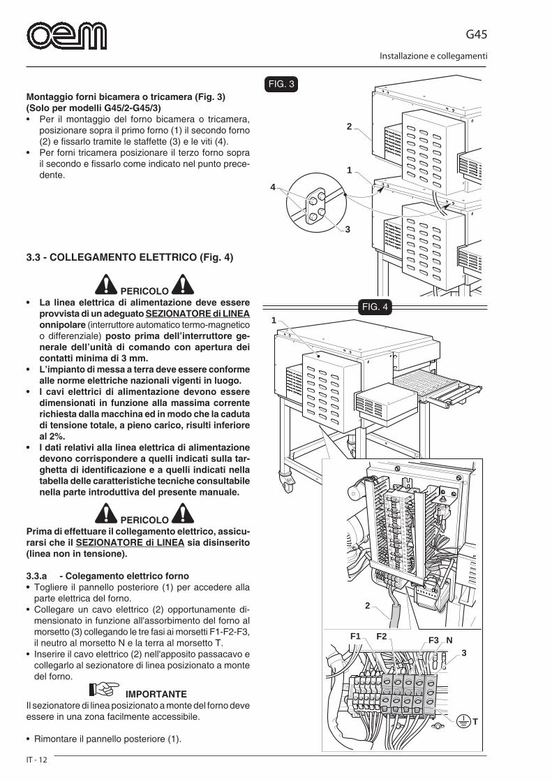
Montaggio forni bicamera o tricamera (Fig. 3)(Solo per modelli G45/2-G45/3)• Per il montaggio del forno bicamera o tricamera,
posizionare sopra il primo forno (1) il secondo forno (2) e fi ssarlo tramite le staffette (3) e le viti (4).
• Per forni tricamera posizionare il terzo forno sopra il secondo e fi ssarlo come indicato nel punto prece-dente.
3.3 - COLLEGAMENTO ELETTRICO (Fig. 4)
PERICOLO • La linea elettrica di alimentazione deve essere
provvista di un adeguato SEZIONATORE di LINEA onnipolare (interruttore automatico termo-magnetico o differenziale) posto prima dell’interruttore ge-nerale dell’unità di comando con apertura dei contatti minima di 3 mm.
• L’impianto di messa a terra deve essere conforme alle norme elettriche nazionali vigenti in luogo.
• I cavi elettrici di alimentazione devono essere dimensionati in funzione alla massima corrente richiesta dalla macchina ed in modo che la caduta di tensione totale, a pieno carico, risulti inferiore al 2%.
• I dati relativi alla linea elettrica di alimentazione devono corrispondere a quelli indicati sulla tar-ghetta di identifi cazione e a quelli indicati nella tabella delle caratteristiche tecniche consultabile nella parte introduttiva del presente manuale.
PERICOLO Prima di effettuare il collegamento elettrico, assicu-rarsi che il SEZIONATORE di LINEA sia disinserito (linea non in tensione).
3.3.a - Colegamento elettrico forno• Togliere il pannello posteriore (1) per accedere alla
parte elettrica del forno.• Collegare un cavo elettrico (2) opportunamente di-
mensionato in funzione all'assorbimento del forno al morsetto (3) collegando le tre fasi ai morsetti F1-F2-F3, il neutro al morsetto N e la terra al morsetto T.
• Inserire il cavo elettrico (2) nell'apposito passacavo e collegarlo al sezionatore di linea posizionato a monte del forno.
IMPORTANTEIl sezionatore di linea posizionato a monte del forno deve essere in una zona facilmente accessibile.
• Rimontare il pannello posteriore (1).

G45
Dati tecnici - Trasporto e disimballo
IT - 13
FIG. 5
1
FIG. 6
200 mm
1000 mm
PERICOLO Per i forni bicamera e tricamera ogni forno deve essere collegato ad un apposito sezionatore di li-nea, non è possibile collegare più forni ad un solo sezionatore di linea.
3.3.b - Collegamento equipotenziale (Fig. 5)L'apparecchio deve essere inserito in un sistema equi-potenziale la cui effi cacia deve essere verifi cata secondo le norme vigenti.Il collegamento deve essere effettuato in cascata tra i vari componenti del forno utilizzando la vite (1) posizio-nata nella parte posteriore dello stesso.
3.4 - POSIZIONAMENTO FORNO (Fig.6)
PERICOLO Il forno NON deve essere installato a ridosso di pareti infi ammabili come mobili, pareti divisorie, rivestimenti in perlinato, ecc.... Si raccomanda di mantenere una distanza di sicurezza di almeno 20 cm dalla parete posteriore del forno. La pavimentazione sopra il quale è installato il forno non deve essere di materiale infi ammabile.
• Posizionare il forno sulla zona defi nitiva rispettando le indicazioni riportate nella fi gura 6 in quanto esse indicano le distanze minime necessarie affi nchè il forno possa funzionare correttamente.
• Bloccare la posizione del forno frenando le ruote (op-tional) posizionate sul lato comandi.
3.5 - PRIMA ACCENSIONE
PERICOLO Alla fi ne dell'installazione e prima di accendere il for-no pulire accuratamente l'interno come indicato nel capitolo "Manutenzione" controllando che all'interno non vi siano corpi estranei o infi ammabili.
• Accendere il forno come indicato nel paragrafo funzio-namento controllando che che raggiunga correttamen-te la temperatura impostata e che siano funzionanti le varie opzioni.
G45
Installazione e collegamenti
IT - 14
FIG. 7
FIG. 8
FIG. 9
42
3
1
453
2
1
5
2
13
FIG. 10
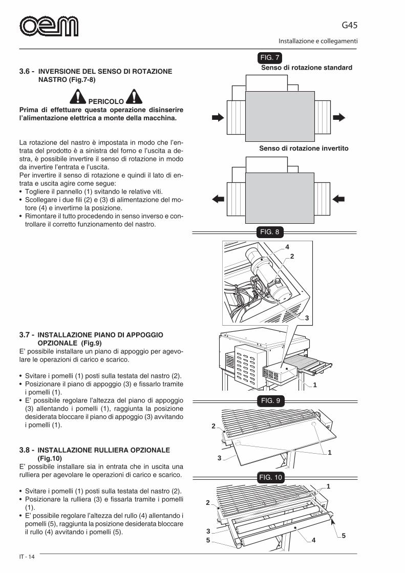
3.6 - INVERSIONE DEL SENSO DI ROTAZIONE NASTRO (Fig.7-8)
PERICOLO Prima di effettuare questa operazione disinserire l’alimentazione elettrica a monte della macchina.
La rotazione del nastro è impostata in modo che l’en-trata del prodotto è a sinistra del forno e l’uscita a de-stra, è possibile invertire il senso di rotazione in modo da invertire l’entrata e l’uscita.Per invertire il senso di rotazione e quindi il lato di en-trata e uscita agire come segue:• Togliere il pannello (1) svitando le relative viti.• Scollegare i due fi li (2) e (3) di alimentazione del mo-
tore (4) e invertirne la posizione.• Rimontare il tutto procedendo in senso inverso e con-
trollare il corretto funzionamento del nastro.
Senso di rotazione standard
Senso di rotazione invertito
3.7 - INSTALLAZIONE PIANO DI APPOGGIO OPZIONALE (Fig.9)E’ possibile installare un piano di appoggio per agevo-lare le operazioni di carico e scarico.
• Svitare i pomelli (1) posti sulla testata del nastro (2).• Posizionare il piano di appoggio (3) e fi ssarlo tramite
i pomelli (1).• E’ possibile regolare l’altezza del piano di appoggio
(3) allentando i pomelli (1), raggiunta la posizione desiderata bloccare il piano di appoggio (3) avvitando i pomelli (1).
3.8 - INSTALLAZIONE RULLIERA OPZIONALE (Fig.10)E’ possibile installare sia in entrata che in uscita una rulliera per agevolare le operazioni di carico e scarico.
• Svitare i pomelli (1) posti sulla testata del nastro (2).• Posizionare la rulliera (3) e fi ssarla tramite i pomelli
(1).• E’ possibile regolare l’altezza del rullo (4) allentando i
pomelli (5), raggiunta la posizione desiderata bloccare il rullo (4) avvitando i pomelli (5).
G45
Sicurezze
IT - 15
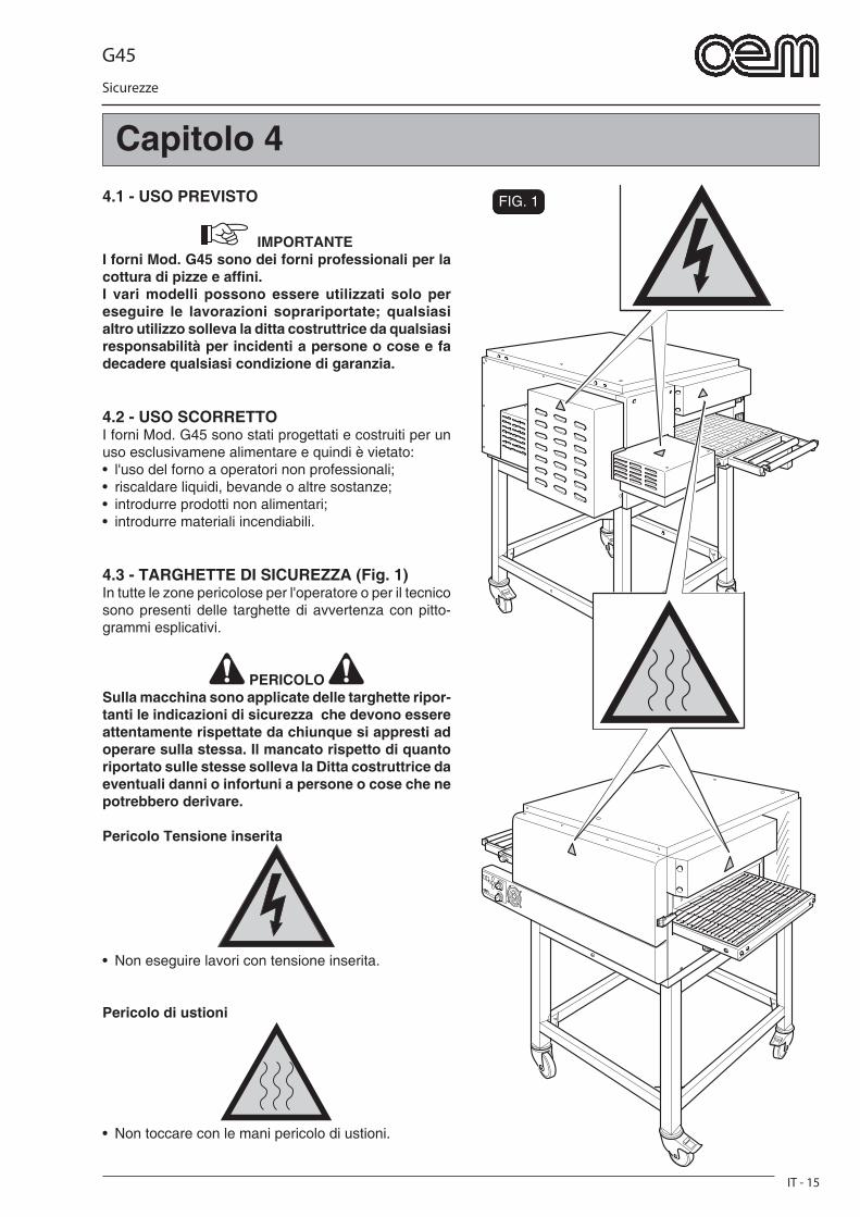
FIG. 14.1 - USO PREVISTO
IMPORTANTE I forni Mod. G45 sono dei forni professionali per la cottura di pizze e affi ni.I vari modelli possono essere utilizzati solo per eseguire le lavorazioni soprariportate; qualsiasi altro utilizzo solleva la ditta costruttrice da qualsiasi responsabilità per incidenti a persone o cose e fa decadere qualsiasi condizione di garanzia.
4.2 - USO SCORRETTOI forni Mod. G45 sono stati progettati e costruiti per un uso esclusivamene alimentare e quindi è vietato:• l'uso del forno a operatori non professionali;• riscaldare liquidi, bevande o altre sostanze;• introdurre prodotti non alimentari;• introdurre materiali incendiabili.
4.3 - TARGHETTE DI SICUREZZA (Fig. 1)In tutte le zone pericolose per l'operatore o per il tecnico sono presenti delle targhette di avvertenza con pitto-grammi esplicativi.
PERICOLO Sulla macchina sono applicate delle targhette ripor-tanti le indicazioni di sicurezza che devono essere attentamente rispettate da chiunque si appresti ad operare sulla stessa. Il mancato rispetto di quanto riportato sulle stesse solleva la Ditta costruttrice da eventuali danni o infortuni a persone o cose che ne potrebbero derivare.
Pericolo Tensione inserita
• Non eseguire lavori con tensione inserita.
Pericolo di ustioni
• Non toccare con le mani pericolo di ustioni.
Capitolo 4
G45
Sicurezze
IT - 16
FIG. 3
O
O
O
T
AA
B
A
2
1
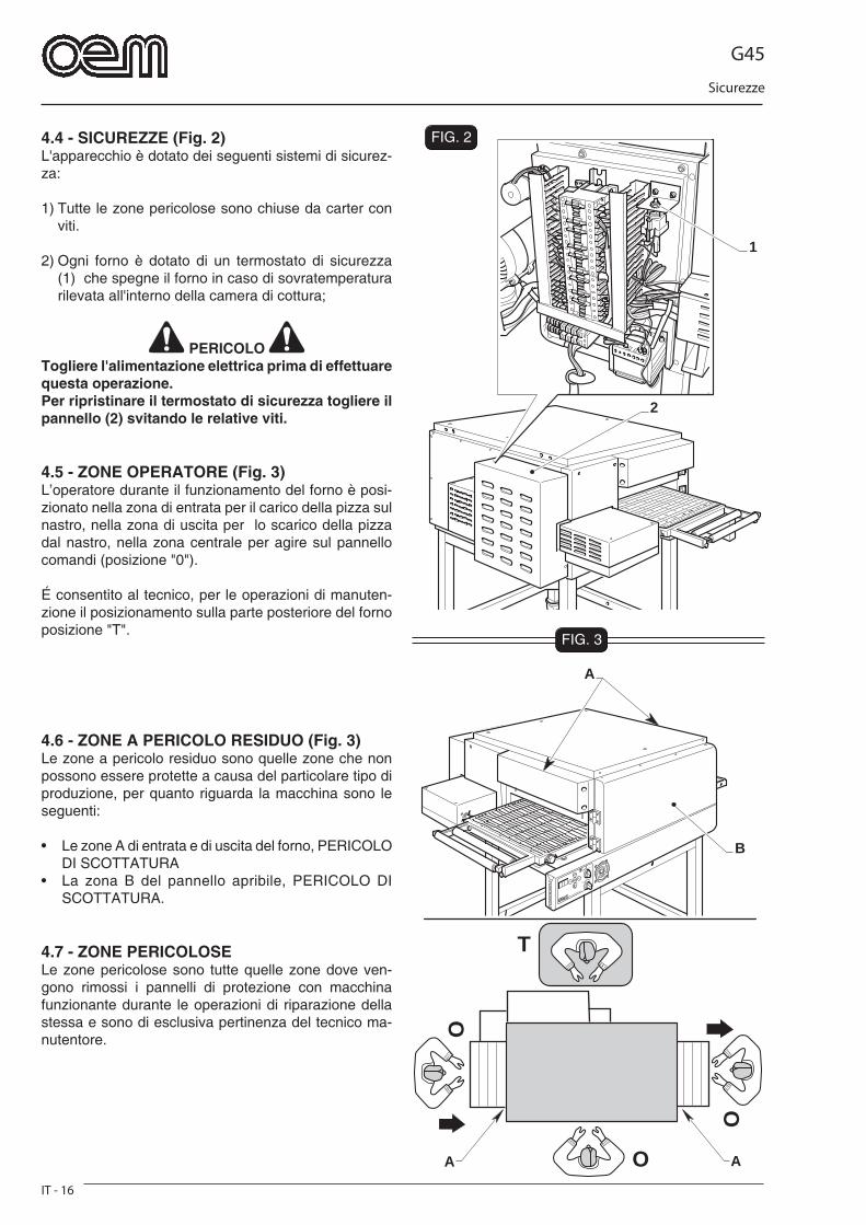
FIG. 24.4 - SICUREZZE (Fig. 2)L'apparecchio è dotato dei seguenti sistemi di sicurez-za:
1) Tutte le zone pericolose sono chiuse da carter con viti.
2) Ogni forno è dotato di un termostato di sicurezza (1) che spegne il forno in caso di sovratemperatura rilevata all'interno della camera di cottura;
PERICOLO Togliere l'alimentazione elettrica prima di effettuare questa operazione.Per ripristinare il termostato di sicurezza togliere il pannello (2) svitando le relative viti.
4.5 - ZONE OPERATORE (Fig. 3)L’operatore durante il funzionamento del forno è posi-zionato nella zona di entrata per il carico della pizza sul nastro, nella zona di uscita per lo scarico della pizza dal nastro, nella zona centrale per agire sul pannello comandi (posizione "0").
É consentito al tecnico, per le operazioni di manuten-zione il posizionamento sulla parte posteriore del forno posizione "T".
4.6 - ZONE A PERICOLO RESIDUO (Fig. 3)Le zone a pericolo residuo sono quelle zone che non possono essere protette a causa del particolare tipo di produzione, per quanto riguarda la macchina sono le seguenti:
• Le zone A di entrata e di uscita del forno, PERICOLO DI SCOTTATURA
• La zona B del pannello apribile, PERICOLO DI SCOTTATURA.
4.7 - ZONE PERICOLOSELe zone pericolose sono tutte quelle zone dove ven-gono rimossi i pannelli di protezione con macchina funzionante durante le operazioni di riparazione della stessa e sono di esclusiva pertinenza del tecnico ma-nutentore.
G45
Funzionamento
IT - 17
Capitolo 5FIG. 1
2
6
7
54 3
8
1
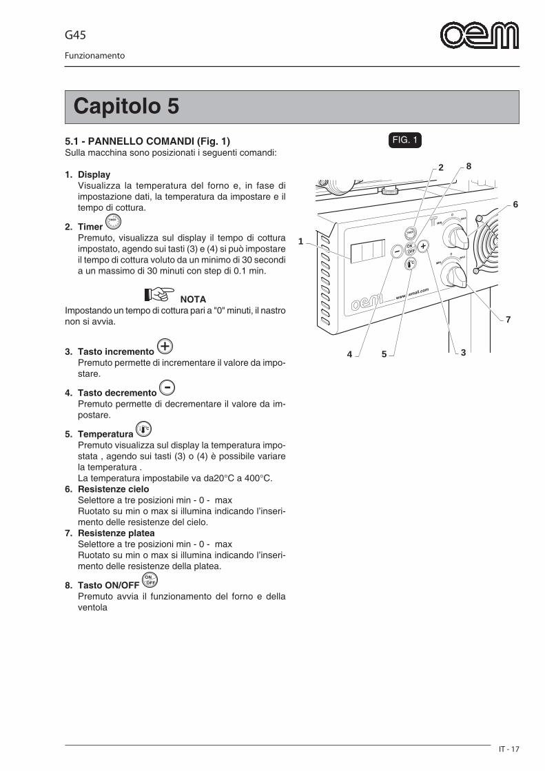
5.1 - PANNELLO COMANDI (Fig. 1)Sulla macchina sono posizionati i seguenti comandi:
1. Display Visualizza la temperatura del forno e, in fase di
impostazione dati, la temperatura da impostare e il tempo di cottura.
2. Timer Premuto, visualizza sul display il tempo di cottura
impostato, agendo sui tasti (3) e (4) si può impostare il tempo di cottura voluto da un minimo di 30 secondi a un massimo di 30 minuti con step di 0.1 min.
NOTA Impostando un tempo di cottura pari a "0" minuti, il nastro non si avvia.
3. Tasto incremento Premuto permette di incrementare il valore da impo-
stare.
4. Tasto decremento Premuto permette di decrementare il valore da im-
postare.
5. Temperatura Premuto visualizza sul display la temperatura impo-
stata , agendo sui tasti (3) o (4) è possibile variare la temperatura .
La temperatura impostabile va da20°C a 400°C.6. Resistenze cielo Selettore a tre posizioni min - 0 - max Ruotato su min o max si illumina indicando l’inseri-
mento delle resistenze del cielo.7. Resistenze platea Selettore a tre posizioni min - 0 - max Ruotato su min o max si illumina indicando l’inseri-
mento delle resistenze della platea.
8. Tasto ON/OFF Premuto avvia il funzionamento del forno e della
ventola
G45
Funzionamento
IT - 18
FIG. 2
3
4
21
7
6
5
FIG. 3
3
4
2
1
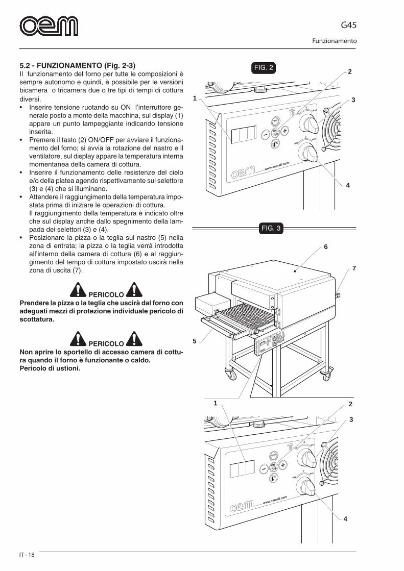
5.2 - FUNZIONAMENTO (Fig. 2-3)Il funzionamento del forno per tutte le composizioni è sempre autonomo e quindi, è possibile per le versioni bicamera o tricamera due o tre tipi di tempi di cottura diversi.• Inserire tensione ruotando su ON l’interruttore ge-
nerale posto a monte della macchina, sul display (1) appare un punto lampeggiante indicando tensione inserita.
• Premere il tasto (2) ON/OFF per avviare il funziona-mento del forno; si avvia la rotazione del nastro e il ventilatore, sul display appare la temperatura interna momentanea della camera di cottura.
• Inserire il funzionamento delle resistenze del cielo e/o della platea agendo rispettivamente sul selettore (3) e (4) che si illuminano.
• Attendere il raggiungimento della temperatura impo-stata prima di iniziare le operazioni di cottura.
Il raggiungimento della temperatura è indicato oltre che sul display anche dallo spegnimento della lam-pada dei selettori (3) e (4).
• Posizionare la pizza o la teglia sul nastro (5) nella zona di entrata; la pizza o la teglia verrà introdotta all’interno della camera di cottura (6) e al raggiun-gimento del tempo di cottura impostato uscirà nella zona di uscita (7).
PERICOLO Prendere la pizza o la teglia che uscirà dal forno con adeguati mezzi di protezione individuale pericolo di scottatura.
PERICOLO Non aprire lo sportello di accesso camera di cottu-ra quando il forno è funzionante o caldo.Pericolo di ustioni.

G45
Funzionamento
IT - 19
FIG. 4
1
6
7
53 2
4
1
2
FIG. 5
5.3 - MODIFICA IMPOSTAZIONI (Fig.4)In funzione all’esperienza, al tipo di impasto e al tipo di prodotto da cuocere è possibile variare le impostazioni della macchina.I parametri impostabili sono :• Il tempo di cottura che equivale al tempo di traslazione
del nastro , più precisamente al tempo che la pizza o il prodotto da cuocere rimane all’interno della camera di cottura.
Per impostare il tempo di cottura premere il pulsante (1) e agire sui tasti (2) e (3) per aumentare o diminuire il tempo, il tempo impostato si visualizza sul display (4).
• La temperatura Per impostare la temperatura premere il tasto (5) e
agire sul sui tasti (2) e (3) per aumentare o diminuire la temperatura, la temperatura impostata si visualizza sul display (4).
E’ inoltre possibile aumentare o diminuire la cottura nel-la parte inferiore o superiore agendo sui selettori (6) o (7) posizionando per esempio il selettore del cielo su Min e il selettore della platea su Max.
IMPORTANTE Effettuare alcune prove di cottura per trovare i parametri corretti.
5.4 - REGOLAZIONE ALTEZZA BOCCA (Fig.5)
PERICOLO Questa regolazione deve essere fatta con macchi-na spenta e fredda, pericolo di ustioni.
E’ possibile, per aumentare il rendimento del forno, re-golare l’altezza della bocca di entrata e uscita; si con-siglia di regolare la lamiera (1) 1-2 cm sopra il prodotto infornato.Per la regolazione allentare i pomelli (2), a regolazione ultimata avvitare i pomelli (2).
G45
Funzionamento
IT - 20
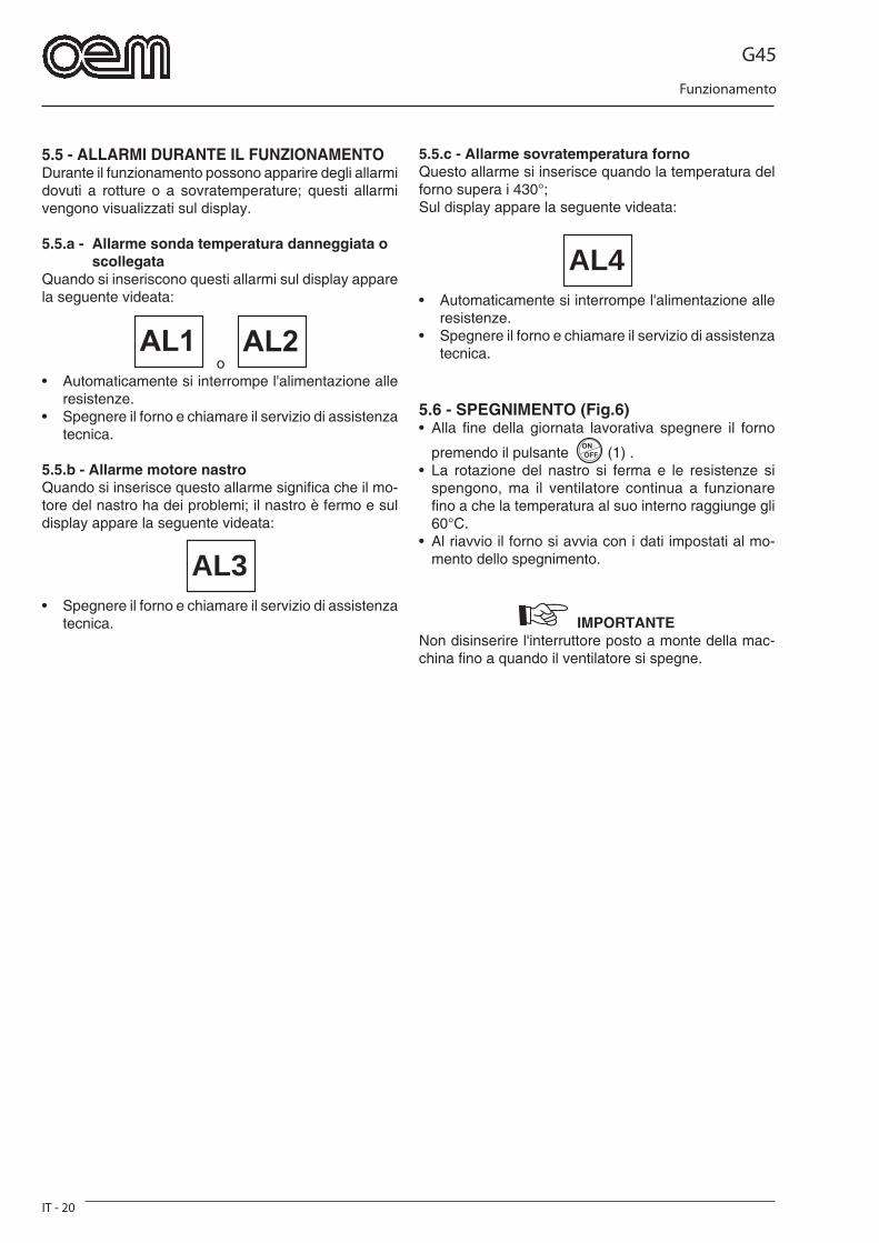
5.5 - ALLARMI DURANTE IL FUNZIONAMENTODurante il funzionamento possono apparire degli allarmi dovuti a rotture o a sovratemperature; questi allarmi vengono visualizzati sul display. 5.5.a - Allarme sonda temperatura danneggiata o scollegataQuando si inseriscono questi allarmi sul display appare la seguente videata:
o • Automaticamente si interrompe l'alimentazione alle
resistenze.• Spegnere il forno e chiamare il servizio di assistenza
tecnica.
5.5.b - Allarme motore nastroQuando si inserisce questo allarme signifi ca che il mo-tore del nastro ha dei problemi; il nastro è fermo e sul display appare la seguente videata:
AL3• Spegnere il forno e chiamare il servizio di assistenza
tecnica.
5.5.c - Allarme sovratemperatura fornoQuesto allarme si inserisce quando la temperatura del forno supera i 430°;Sul display appare la seguente videata:
AL4• Automaticamente si interrompe l'alimentazione alle
resistenze.• Spegnere il forno e chiamare il servizio di assistenza
tecnica.
5.6 - SPEGNIMENTO (Fig.6)• Alla fi ne della giornata lavorativa spegnere il forno
premendo il pulsante (1) .• La rotazione del nastro si ferma e le resistenze si
spengono, ma il ventilatore continua a funzionare fi no a che la temperatura al suo interno raggiunge gli 60°C.
• Al riavvio il forno si avvia con i dati impostati al mo-mento dello spegnimento.
IMPORTANTE Non disinserire l'interruttore posto a monte della mac-china fi no a quando il ventilatore si spegne.

G45
Funzionamento
IT - 21
FIG. 6
1
5.7 - MALFUNZIONAMENTI,CAUSE E RIMEDI (Fig.7)
- Il forno non si accende:
• Controllare che vi sia allacciamento elettrico. • Controllare che sia inserito l'interruttore generale• Chiamare il servizio di assistenza tecnica.
- Il prodotto cucinato non risulta cotto uniforme-mente:
• Regolare il tempo di cottura • Regolare la temperatura del forno
- Malfunzionamento forno:
• Non si raggiunge la temperatura impostata: Resistenze guaste Controllare collegamento elettrico del forno Chiamare il servizio di assistenza tecnica.
PERICOLO Per tutti gli altri problemi rivolgersi al Servizio di assistenza tecnica
G45
Funzionamento
IT - 22
1
6
3
4
8 9
7
10
2
5
FIG. 1
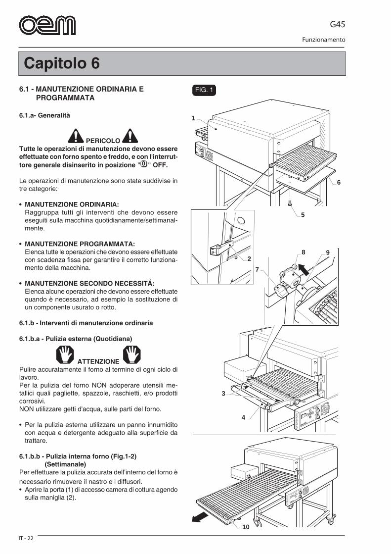
Capitolo 66.1 - MANUTENZIONE ORDINARIA E PROGRAMMATA
6.1.a- Generalità
PERICOLO Tutte le operazioni di manutenzione devono essere effettuate con forno spento e freddo, e con l'interrut-tore generale disinserito in posizione " " OFF.
Le operazioni di manutenzione sono state suddivise in tre categorie:
• MANUTENZIONE ORDINARIA: Raggruppa tutti gli interventi che devono essere
eseguiti sulla macchina quotidianamente/settimanal-mente.
• MANUTENZIONE PROGRAMMATA: Elenca tutte le operazioni che devono essere effettuate
con scadenza fi ssa per garantire il corretto funziona-mento della macchina.
• MANUTENZIONE SECONDO NECESSITÁ: Elenca alcune operazioni che devono essere effettuate
quando è necessario, ad esempio la sostituzione di un componente usurato o rotto.
6.1.b - Interventi di manutenzione ordinaria
6.1.b.a - Pulizia esterna (Quotidiana)
ATTENZIONE Pulire accuratamente il forno al termine di ogni ciclo di lavoro.Per la pulizia del forno NON adoperare utensili me-tallici quali pagliette, spazzole, raschietti, e/o prodotti corrosivi.NON utilizzare getti d'acqua, sulle parti del forno.
• Per la pulizia esterna utilizzare un panno innumidito con acqua e detergente adeguato alla superfi cie da trattare.
6.1.b.b - Pulizia interna forno (Fig.1-2) (Settimanale)Per effettuare la pulizia accurata dell’interno del forno è necessario rimuovere il nastro e i diffusori.• Aprire la porta (1) di accesso camera di cottura agendo
sulla maniglia (2).

G45
Manutenzione
IT - 23
FIG. 2
12
11
14
13 PERICOLO Le operazioni di rimozione dei componenti devono essere effettuate indossando guanti di protezione.
• Svitare i pomelli (3) e rimuovere le eventuali rulliere e/o piani di appoggio (4).
• Svitare i pomelli (5) e rimuovere i vassoi (6) poste sotto al nastro in entrata e uscita della macchina.
• Allentare il pomello (7) e sganciare il giunto (8) spo-standolo verso il motore liberando l’albero (9) del nastro.
• Rimuovere il nastro (10) sfi landolo dalla bocca di entrata.
• Pulire il nastro dai residui di cottura con una spazzola a setole dure e risciacquare con acqua.
• Sganciare l'aletta a molla (11) fi no a liberare i perni quindi estrarre il diffusore superiore (12).
• Sganciare la lamiera a molla (13) fi no a liberare i perni quindi estrarre il diffusore inferiore (14).
• Pulire i diffusori aspirando con un’aspirapolvere gli eventuali residui di cottura e pulire con un panno umido.
• Aspirare con un’aspirapolvere l’interno della camera di cottura tutti i residui di cottura.
• Rimontare il tutto procedendo in senso inverso .
G45
Manutenzione
IT - 24
FIG. 3
1
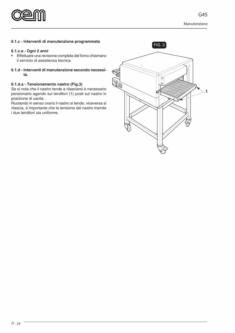
6.1.c - Interventi di manutenzione programmata
6.1.c.a - Ogni 2 anni• Effettuare una revisione completa del forno chiamano
il servizio di assistenza tecnica.
6.1.d - Interventi di manutenzione secondo necessi-tà.
6.1.d.a - Tensionamento nastro (Fig.3)Se si nota che il nastro tende a rilasciarsi è necessario pensionarlo agendo sui tenditori (1) posti sul nastro in posizione di uscita .Ruotando in senso orario il nastro si tende, viceversa si rilascia, è importante che la tensione del nastro tramite i due tenditori sia uniforme.
G45
Smontaggio - Demolizione - Smaltimento
IT - 25
Capitolo 7
7.1 - SMONTAGGIO DELLA MACCHINAQualora sia necessario procedere allo smontaggio della macchina per procedere successivamente ad una nuova installazione occorre procedere in senso inverso a quanto riportato nel capitolo "Installazione".
PERICOLO Prima di procedere allo smontaggio dell'impianto staccare l'alimentazione elettrica.
Le operazioni di montaggio devono essere eseguite da personale tecnico qualifi cato ed abilitato a tali interventi.
ATTENZIONE Nel caso sia necessario smontare la macchina, o alcuni suoi componenti, in maniera differente rispetto a quanto descritto consultare la ditta costruttrice, op-pure il proprio Agente, consultando i recapiti riportati nella terza pagina della presente pubblicazione.
7.2 - DEMOLIZIONE DELLA MACCHINA
Per la salvaguardia dell’ambiente, procedere secondo la normativa lo-cale vigente.Quando l’apparecchio non è più utilizzabile nè riparabile, procedere allo smaltimento differenziato dei componenti.
L’apparecchiatura elettrica non può essere smaltita come un rifi uto urbano, ma è necessario rispettare la raccolta separata introdotta dalla disciplina speciale per lo smaltimento dei rifi uti derivati da apparec-chiature elettriche (dlg n 151 del 25/7/05 - 2002/96/CE - 2003/108/CE)Le apparecchiature elettriche sono contrassegnate da un simbolo recante un contenitore di spazzatura su ruote barrato. Il simbolo indica che l’apparec-chiatura è stata immessa sul mercato dopo il 13 agosto 2005 e che deve essere oggetto di raccolta separata.Lo smaltimento inadeguato o abusivo delle appa-recchiature oppure un uso improprio delle stesse, in considerazione delle sostanze e dei materiali conte-nuti può causare danni alle persone e all’ambiente. Lo smaltimento dei rifi uti elettrici che non rispetti le norme vigenti comporta l’applicazione di sanzioni amministrative e penali.
ATTENZIONE Per quanto concerne lo smaltimento di sostanze nocive (lubrifi canti, solventi, prodotti vernicianti, etc.) consultare il paragrafo successivo.
7.3 - SMALTIMENTO DELLE SOSTANZE NOCI-VE
Per procedere allo smaltimento di dette sostanze con-sultare quanto prescritto dalle Normative Vigenti nel singolo paese ed operare di conseguenza.
ATTENZIONE Qualunque irregolarità commessa dal Cliente prima, durante o dopo la rottamazione e lo smaltimento dei componenti della macchina, nell’interpretazione ed applicazione delle Normative Vigenti in materia, è di esclusiva responsabilità dello Stesso.
G45
Schema elettrico
IT - 26
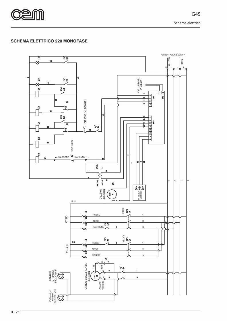
SCHEMA ELETTRICO 220 MONOFASE
ALIMENTAZIONE 230/1-N
SO
ND
A D
I TE
MP
ER
ATU
RA
MARRONE MARRONETE
RM
. MO
T.
ENCODER
MO
TORE M
1
MO
TOR
EN
AS
TRO
TER
MO
STA
TO D
I SIC
.
CIE
LOP
LATE
A
ROSSO
NERO
MARRONE
ROSSO
NERO
BIANCO
BLU
MO
TOR
EV
EN
TILATO
RE
FOR
NO
RO
SS
O+
BIA
NC
ON
ER
OVE
NTILA
TOR
EP
AN
NE
LLO
CO
MA
ND
I
BLU
VE
NTILA
TOR
EQ
UA
DR
O
ELE
TTRIC
O
CIE
LOP
LATE
A
FAS
E
NE
UTR
O
G45
Schema elettrico
IT - 27
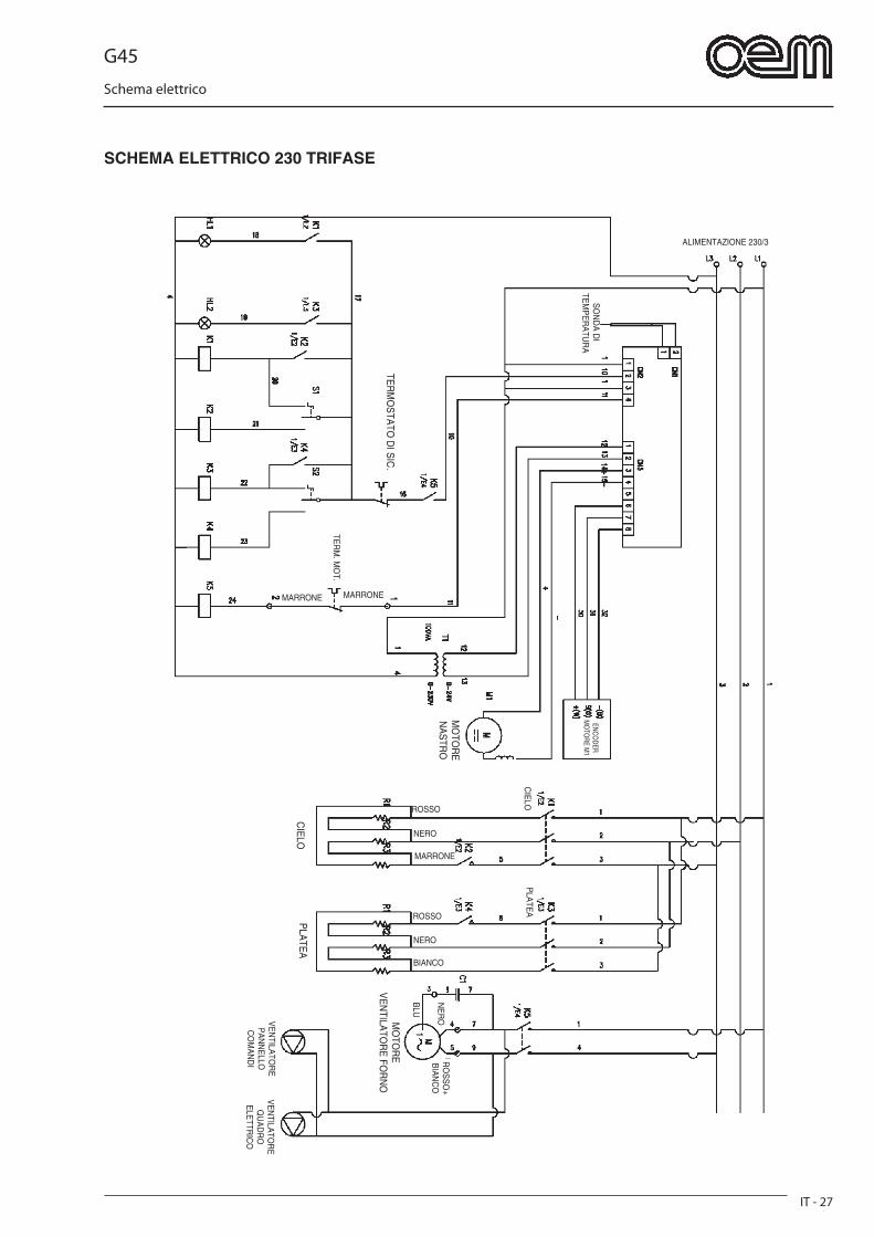
SCHEMA ELETTRICO 230 TRIFASE
ALIMENTAZIONE 230/3
SO
ND
A D
I TE
MP
ER
ATU
RA
MARRONE MARRONE
TER
M. M
OT.
ENCODER
MO
TORE M
1
MO
TOR
EN
AS
TRO
TER
MO
STA
TO D
I SIC
.
CIE
LOP
LATE
A
ROSSO
NERO
MARRONE
ROSSO
NERO
BIANCO
MO
TOR
EV
EN
TILATO
RE
FOR
NO
RO
SS
O+
BIA
NC
ON
ER
OVE
NTILA
TOR
EP
AN
NE
LLO
CO
MA
ND
I
BLU
VE
NTILA
TOR
EQ
UA
DR
O
ELE
TTRIC
O
CIE
LOP
LATE
A

G45
Schema elettrico
IT - 28
SCHEMA ELETTRICO 400 TRIFASE
ALIMENTAZIONE 400/3-N
SO
ND
A D
I TE
MP
ER
ATU
RA
MARRONE MARRONE
TER
M. M
OT.
ENCODER
MO
TORE M
1
MO
TOR
EN
AS
TRO
TER
MO
STA
TO D
I SIC
.
CIE
LOP
LATE
A
ROSSO
NERO
MARRONE
ROSSO
NERO
BIANCO
BLU
MO
TOR
EV
EN
TILATO
RE
FOR
NO
RO
SS
O+
BIA
NC
ON
ER
OVE
NTILA
TOR
EP
AN
NE
LLO
CO
MA
ND
I
BLU
VE
NTILA
TOR
EQ
UA
DR
O
ELE
TTRIC
O
CIE
LOP
LATE
A
BLU

G45
Schema elettrico
IT - 29
LEGENDA
K1 = Teleruttore principale resistenza cieloK2 = Teleruttore economia resistenza cieloK3 = Teleruttore principale resistenza plateaK4 = Teleruttore economia resistenza plateaK5 = Teleruttore ventilatore fornoHL1 = Lampada segnalazione resistenza cielo inseritaHL2 = Lampada segnalazione resistenza platea inseritaS1 = Selettore resistenza cieloS2 = Selettore resistenza plateaT1 = Trasformatore 0-230/0-24V alimentazione scheda comandi
G45
General specifi cations and warning
EN - 1
ENGLISH
CHAPTER .......................................................1Chapter for the technician and operator1.1 GENERAL WARNINGS ..................................... Page EN-31.2 REFERENCE NORMATIVES ............................ Page EN-41.3 DESCRIPTION OF THE SYMBOLS .................. Page EN-41.4 MACHINE COMPOSITION ................................ Page EN-41.5 PREARRANGEMENTS AT PURCHASER’S CHARGE ............................ Page EN-51.6 EMERGENCY OPERATIONS IN CASE OF FIRE .............................................. Page EN-51.7 EXPLOSION RISK ............................................. Page EN-51.8 ACOUSTIC PRESSURE LEVEL ....................... Page EN-5
CHAPTER .......................................................2Chapter for the technician- OVERALL DIMENSIONS ........................................ Page EN-62.1 TECHNICAL SFEATURES .............................. Page EN-72.2 TRANSPORT ..................................................... Page EN-8 2.2.a Shipment ................................................... Page EN-8 2.2.b Lifting of the packing ................................. Page EN-8 2.2.c Storage ...................................................... Page EN-82.3 RECEPTION OF THE MACHINE ....................... Page EN-92.4 UNPACKING ...................................................... Page EN-92.5 IDENTIFICATION OF THE COMPONENTS .... Page EN-102.6 IDENTIFICATION OF THE MACHINE ............. Page EN-10
CHAPTER .......................................................3Chapter for the technician3.1 LIFTING OF THE MACHINE ............................ Page EN-113.2 COMPONENTS’ ASSEMBLY ...................... Page EN-113.3 ELECTRICAL CONNECTION ......................... Page EN-12 3.3.a Electric oven connection ......................... Page EN-12 3.3.b Unipotential connection ......................... Page EN-133.4 OVEN POSITIONNING .................................... Page EN-133.5 FIRST STARTING ............................................ Page EN-133.6 INVERSION OF BELT ROTATION’S DIRECTION ..................................................... Page EN-143.7 INSTALLATION OF OPTIONAL SUPPORTING SURFACE ............................ Page EN-143.8 INSTALLATION OF AN OPTIONAL ROLLER UNIT ............................................... Page EN-14
CHAPTER .......................................................4Chapter for the technician and operator4.1 EXPECTED USE ............................................ Page EN-154.2 INCORRECT USE ......................................... Page EN-154.3 SAFETY PLATES ........................................... Page EN-154.4 SAFETY DEVICES ......................................... Page EN-164.5 OPERATOR’S AREAS ................................... Page EN-164.6 RESIDUAL DANGER AREAS ....................... Page EN-164.7 DANGEROUS AREAS ................................... Page EN-16
CHAPTER .......................................................5Chapter for the technician and operator5.1 CONTROL BOARD ........................................ Page EN-175.2 RUNNING ........................................................ Page EN-185.3 SETTINGS MODIFICATION .......................... Page EN-195.4 ADJUSTMENT OF THE OVEN’S OPENING HEIGHT ......................................... Page EN-195.5 ALARMS DURING RUNNING ....................... Page EN-20 5.5.a Damaged or disconnected temperature detector alarm ....................Page EN-20 5.5.b Belt motor alarm .................................... Page EN-20 5.5.c Overheating alarm ................................. Page EN-205.6 TURNING OFF ............................................... Page EN-205.7 FAILURE, CAUSES AND REMEDIES .......... Page EN-21
CHAPTER .......................................................6Chapter for the technician and operator6.1 ROUTINE AND PLANNED MAINTENANCE ............................................. Page EN-22 6.1.a In general .............................................. Page EN-22 6.1.b Ordinary maintenance ......................... Page EN-22 6.1.b - a Outer cleaning ................................ Page EN-22 6.1.b - b Oven’s internal cleaning ............... Page EN-22 6.1.c Planned maintenance .......................... Page EN-24 6.1.c - a Every 2 years ................................. Page EN-24 6.1.d Maintenance in case of need .............. Page EN-24 6.1.d - a Belt tightening ................................. Page EN-24
CHAPTER .......................................................7Chapter for the technician7.1 DISMANTLING THE MACHINE .................... Page EN-257.2 DEMOLISHING THE MACHINE .................... Page EN-257.3 DISPOSING OF HARMFUL SUBSTANCES Page EN-25
220 SINGLE-PHASE MOTOR WIRING DIAGRAM ..... Page EN-26230 THREE-PHASE MOTOR WIRING DIAGRAM...... Page EN-27400 THREE-PHASE MOTOR WIRING DIAGRAM...... Page EN-28
LEGENDA .............................................................. Page EN-29

G45
General specifi cations and warning
EN - 3
1.1 - GENERAL WARNINGS
- Before setting the machine at work the operator should have carefully red these instructions and have acquired a deep knowledge of the technical specifi cations and control devices.
- To the operator is suggested to attend a training course on the use of the machine.
- Before installing the machine make sure that the used area is compatible with the dimensions and the weight of the machine.
- For the installation or removal of any machine part, the used lifting and handling devices should be suitable to the weight and geometrical characteristics of the part to be lifted or handled.
- Only skilled and authorized personnel is allowed to start adjust or repair the machine. This handbook should be always consulted before to do any work on the machine.
- Mechanical parts and electrical components inside the machine are protected by totally enclosed panels fastened with screws.
- Before cleaning and/or maintaining the machine and be-fore removing any type of protection, make sure that the general switch is on “OFF” position (O), in order to turn off the power while the operator is working.
- The power supply system of the purchaser should be pro-vided with an automatic release device above the machine main switch and with a suitable earthling system complying with the accident prevention regulations.
- In case of repairs to be done on the main switch or in the main switch area, turn off the power of the electrical line.
- Any inspection and maintenance works requiring the removal of the safety protections are made under the responsibility of the user.
Therefore it is recommended that the above mentioned works are done by authorized and skilled personnel only.
- Make sure that all safety devices (barriers, protections, carter, micro-switches, etc.) have not been tampered and are perfectly working. On the contrary, they should be re-paired.
- Do not remove the safety devices.
- In order to avoid personal risks, only suitable tools should be used, in accordance with the local safety regulations.
- Do not tamper the electric and pneumatic plant or any other mechanism for any reason.
- Do not leave the machine unattended while it is working.
- Wear safety clothing only, approved by the law in force.
- In case of works to be done in a position that cannot be reached from the ground, use safe ladders or lifting devices only, in conformity with the local safety regulations.
- In case of repairs to be done near or under the machine, make sure that:
• there are no machine members that can start working and/or instable parts placed on the machine or near the machine.
- Do not use your hands instead of suitable tools to work on the machine.
- Do not use your hands or other tools to stop any moving parts.
- Do not use matches, lighters or fl ames near the machine.
- YOUR BEST ATTENTION SHOULD BE PAID TO THE WARNING PLATES LOCATED ON THE MACHINE BE-FORE DOING ANY WORK ON THE MACHINE OR NEAR THE MACHINE.
- The user is obliged to keep all the warning plates in legible conditions and, if required, to change their position in order to make them fully visible to the operator.
- Moreover the user is obliged to replace any warning plate that, for any reason, has been damaged or is not clearly legible. New warning plates can be obtained through our Technical Service Centre.
- Stop the machine before doing any repair work.
- In case of malfunction of the machine or damages to its components, get in touch with the maintenance engineer and do not try to repair the machine.
- It is absolutely prohibited to use the machine for other purposes different from those expressly indicated and documented.
The machine should be used always when and how provided by the good technique, in compliance with the EEC machine directive 89/392 and in compliance with the regulations con-cerning health and safety of the workers, as indicated by the local regulations or according to the EEC directive 89/391.
- The manufacturer declines all responsibility for any injury or damage to persons or things arising from inob-servance of the safety regulations and the instructions contained in this manual.
Chapter 1
G45
General specifi cations and warning
EN - 4
- THESE SAFETY REGULATIONS INTEGRATE OR COM-PLEMENT THE LOCAL SAFETY REGULATIONS.
- DO NOT make hurried or inaccurate repairs that may compromise the good running of the machine and the safety of the operator.
- IN CASE OF DOUBT ALWAYS ASK FOR THE PRESENCE OF SKILLED PERSONNEL.
- FOR ANY ELECTRIC/ELECTRONIC OR MECHANIC TAM-PERING OF THE MACHINE BY THE USER OR IN CASE OF A NEGLIGENT USE OF THE MACHINE, THE MANU-FACTURER IS RELIEVED FROM ANY RESPONSIBILITY AND THE USER WILL BE THE ONLY ONE RESPONSIBLE AGAINST THE COMPETENT AUTHORITIES FOR THE ACCIDENT PREVENTION.
1.2 - REFERENCE NORMATIVE
- The machine and its safety components have been manufactured in compliance with the directives indi-cated in the declaration of conformity.
1.3 - DESCRIPTION OF THE SYMBOLS
Many accidents are caused by a poor knowledge of and by a non compliance with the safety regulations to put into practice during the functioning and main-tenance works to be done on the machine. In order to avoid any accidents, read understand and follow all the warnings and cautions contained in this booklet and those written on the plates located on the machine.To identify the safety messages included in this bo-oklet, following symbols have been used:
DANGERThis symbol is used in the safety messages con-tained in the booklet in case of potential danger situations or possibility to cause serious injuries or dead.
ATTENTIONThis symbol is used in the safety messages of the booklet for any danger situation that, if disregarded, may cause small or moderate injuries or damages.The message can be used also in case of danger si-tuations that may cause damages to the machine.
IMPORTANTThis symbol is used in case of precautionary measu-res to be taken in order to avoid any operation that may reduce the life of the machine or for important communication to the operator.
DANGER
For clarity reasons, some illustrations of this booklet show the machine without safety guards. DO NOT USE THE MACHINE WITHOUT SAFETY GUARDS.
1.4 - MACHINE COMPOSITION
Manufacturer’s machines are the results of a conside-rable experience.
• Convection ovens can be single-chamber, double-chamber or three-chambered ovens and are com-posed of a duly insulated stainless steel outer shell, a stainless steel conveyor belt with fi ne links and a convection cooking system functioning by means of resistances.
Hot air recirculation by a fan.• The oven/s are supported by a bearing base.
G45
General specifi cations and warning
EN - 5
1.5 - PREARRANGEMENTS AT PURCHASER’S CHARGE
a) Prearrangement of the installation place.• The purchaser shall prearrange a supporting surface
for the machine as indicated in the chapter “Installa-tion”.
b) Electric prearrangement.• The power system should comply with the local re-
gulations and provided with an effi cient earthing.
• Place an omnipolar sectioning device on the power feed line, above the machine.
• The size of the electric power cables should comply with the maximum current required by the machine, so that the total voltage drop at full charge will be less than 2%.
c) Neutral wire • The machine is equipped with neutral wire, therefore,
a special terminal being identifi ed according to the relevant directions has been prearranged.
1.6 - EMERGENCY OPERATIONS IN CASE OF FIRE
a) In case of fi re turn off the power by disconnecting the main power switch.
b) Put out the fire by means of suitable fire extin-guishers.
DANGER
Do not attempt to put out the fi re by using water.
1.7 - EXPLOSION RISK• The machine is not suitable to be used in a place
with explosion risk.
1.8 - ACOUSTIC PRESSURE LEVELWith GHIBLI G45 ovens, an A acoustic continuous equi-valent weighted pressure level(dB) under the maximum allowed 70dB level is kept.
G45
Technical data - Transport and unpacking
EN - 6
1037
,5
460
750
1250
257,5 242,5
1222
,5
734
520
555 655
160 / 300
172
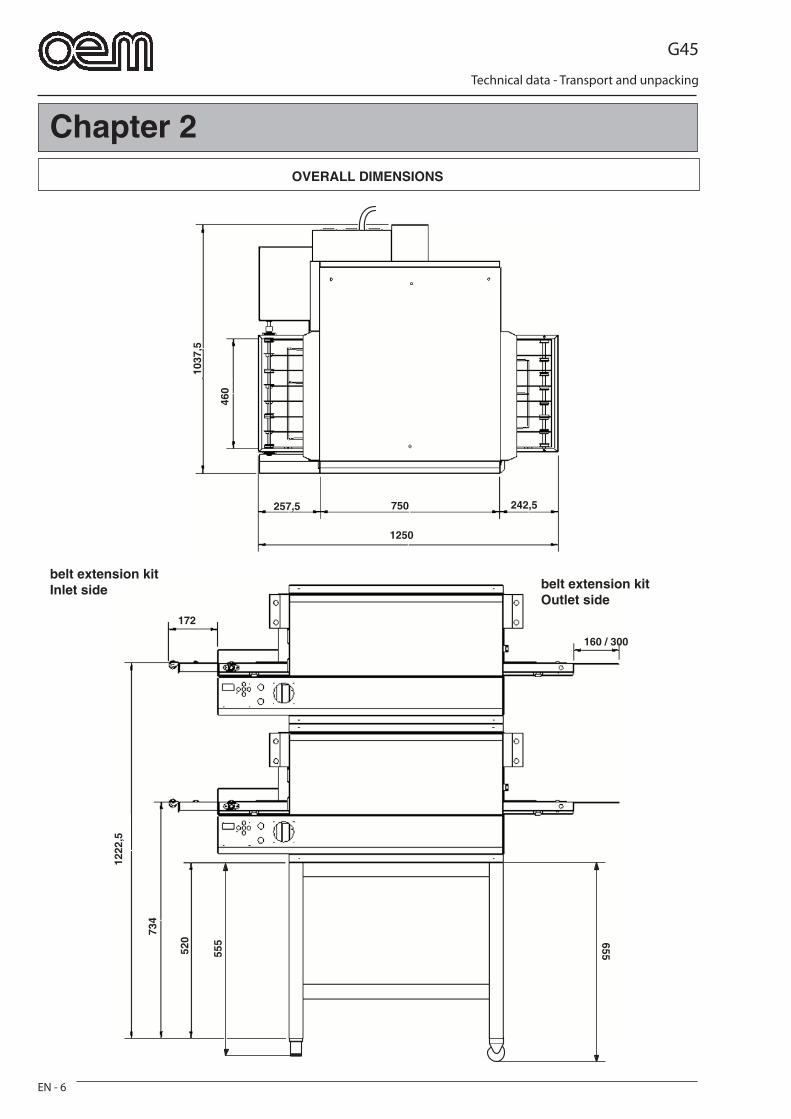
OVERALL DIMENSIONS
Chapter 2
belt extension kit Inlet side belt extension kit
Outlet side

G45
Technical data - Transport and unpacking
EN - 7
2.1 - TECHNICAL FEATURES
Model G45/1 G45/2 G45/3
Electric connection 230V 1 ~ 230V 1 ~ 230V 1 ~ 230V 3 ~ 230V 3 ~ 230V 3 ~ 400V 3 ~ 400V 3 ~ 400V 3 ~ 50Hz 50Hz 50Hz
Power - kW/h - kW-max 12,5 25 37,5
Cable section 3 x 10 mm2 3 x 10 mm2 3 x 10 mm2
230 V - 1 230 V - 1 230 V - 1
4 x 2,5 mm2 4 x 2,5 mm2 4 x 2,5 mm2
230 V - 3 230 V - 3 230 V - 3
5 x 2,5 mm2 5 x 2,5 mm2 5 x 2,5 mm2
400 V - 3 400 V - 3 400 V - 3
Net weight 129 kg 258 kg 387 kg
Relative humidity 10 ÷ 80 %
Model Ceiling Bedpalte Max resistance resistance power
Kw
G45/1 3x2000 W 3x2000 W 12
G45/2 6x2000 W 6x2000 W 24
G45/3 9x2000 W 9x2000 W 36
G45
Technical data - Transport and unpacking
EN - 8
a b
c d
FIG. 2
FIG. 1FIG. 1
FIG. 2
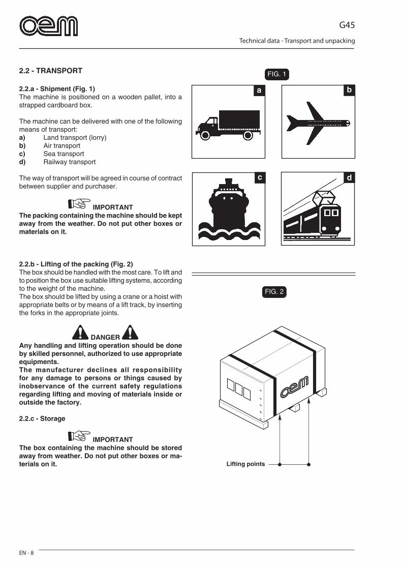
2.2 - TRANSPORT
2.2.a - Shipment (Fig. 1)The machine is positioned on a wooden pallet, into a strapped cardboard box.
The machine can be delivered with one of the following means of transport:a) Land transport (lorry)b) Air transport c) Sea transport d) Railway transport
The way of transport will be agreed in course of contract between supplier and purchaser.
IMPORTANTThe packing containing the machine should be kept away from the weather. Do not put other boxes or materials on it.
2.2.b - Lifting of the packing (Fig. 2)The box should be handled with the most care. To lift and to position the box use suitable lifting systems, according to the weight of the machine.The box should be lifted by using a crane or a hoist with appropriate belts or by means of a lift track, by inserting the forks in the appropriate joints.
DANGER Any handling and lifting operation should be done by skilled personnel, authorized to use appropriate equipments. The manufacturer declines all responsibility for any damage to persons or things caused by inobservance of the current safety regulations regarding lifting and moving of materials inside or outside the factory.
2.2.c - Storage
IMPORTANTThe box containing the machine should be stored away from weather. Do not put other boxes or ma-terials on it. Lifting points

G45
Technical data - Transport and unpacking
EN - 9
FIG. 3
1
1
2
3
2.3 - RECEPTION OF THE MACHINE
Upon reception of the machine make sure that the packing is complete and not damaged. Should the packing be complete, remove it as specify at point 2.4 (aside from different manufacturer’s instructions).Check if the instruction booklet is inside the packing as well as the components specifi ed in the transport documentation.In case any damage or defect is found:
a- Inform immediately the transport company and your agent, both by phone and by registered letter with return receipt;
b- Manufacturer shall also be informed.
2.4 - UNPACKING (Fig. 3)To remove the packing from the machine proceed as follows:• Cut the straps (1) that tie up the carton.• Open the carton (2), by removing the metallic clips.• Remove the cardboard packaging (2).• Check if everything is complete.• Open the door (3) of the oven, remove loose com-
ponents.• Check if the delivery is complying with the PACKING
LIST.
DANGER The packing elements ( plastic bags, carton, nails, etc...) shall be kept away from the reach of the chil-dren, since they are potential danger sources, so, they shall be gathered and sent to special centres to correctly be recycled.
IMPORTANTAny damage or defect or non conformity with the packing list should be immediately reported and, in any case, it should be notifi ed within 8 days from the date of reception of the machine. On the contrary the goods are to be considered as accepted.

G45
Technical data - Transport and unpacking
EN - 10
FIG. 4
7
5
55
4
6
1
2
3
2.5 - IDENTIFICATION OF THE COMPONENTS (Fig. 4)
1. Oven 1 - G45/12. Oven 2 - G45/23. Oven 3 - G45/34. Support5. Wheels (Optional)6. Control board7. Data plate
2.6 - IDENTIFICATION OF THE MACHINE (Fig. 4)The serial number and identifi cation data of the machi-ne are punched on a plate (9) fastened to the machine base.
IMPORTANT The machine serial number should be always men-tioned in your request of technical assistance or in your spare part orders.
G45
Installation and connections
EN - 11
FIG. 2
FIG. 1
4
22
1 1
13
1
3
2
4
65
DANGER
All operations described in this chapter shall be carried out by skilled and authorized technicians, only.
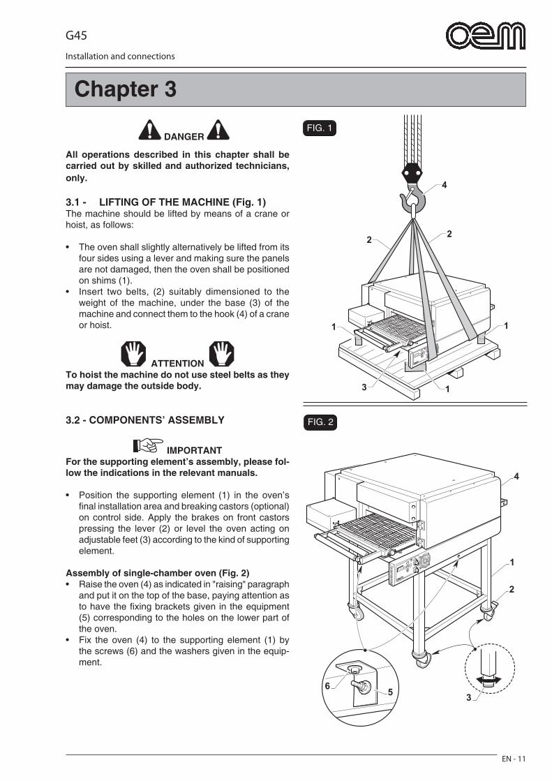
3.1 - LIFTING OF THE MACHINE (Fig. 1)The machine should be lifted by means of a crane or hoist, as follows:
• The oven shall slightly alternatively be lifted from its four sides using a lever and making sure the panels are not damaged, then the oven shall be positioned on shims (1).
• Insert two belts, (2) suitably dimensioned to the weight of the machine, under the base (3) of the machine and connect them to the hook (4) of a crane or hoist.
ATTENTION To hoist the machine do not use steel belts as they may damage the outside body.
3.2 - COMPONENTS’ ASSEMBLY
IMPORTANTFor the supporting element’s assembly, please fol-low the indications in the relevant manuals.
• Position the supporting element (1) in the oven’s fi nal installation area and breaking castors (optional) on control side. Apply the brakes on front castors pressing the lever (2) or level the oven acting on adjustable feet (3) according to the kind of supporting element.
Assembly of single-chamber oven (Fig. 2)• Raise the oven (4) as indicated in "raising" paragraph
and put it on the top of the base, paying attention as to have the fi xing brackets given in the equipment (5) corresponding to the holes on the lower part of the oven.
• Fix the oven (4) to the supporting element (1) by the screws (6) and the washers given in the equip-ment.
Chapter 3
G45
Installation and connections
EN - 12
FIG. 3
FIG. 41
2
T
F3 N
3
F2F1
1
2
3
4
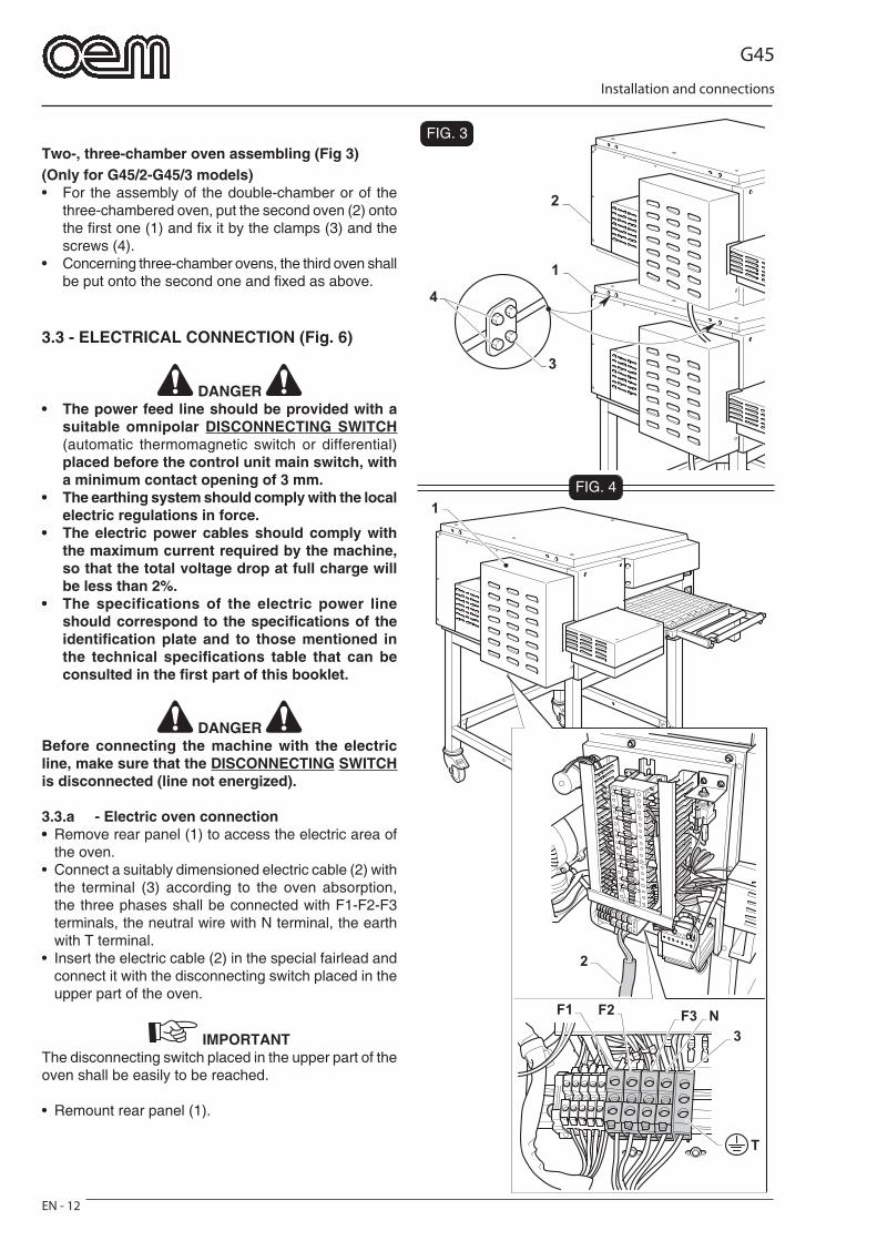
Two-, three-chamber oven assembling (Fig 3)(Only for G45/2-G45/3 models)• For the assembly of the double-chamber or of the
three-chambered oven, put the second oven (2) onto the fi rst one (1) and fi x it by the clamps (3) and the screws (4).
• Concerning three-chamber ovens, the third oven shall be put onto the second one and fi xed as above.
3.3 - ELECTRICAL CONNECTION (Fig. 6)
DANGER • The power feed line should be provided with a
suitable omnipolar DISCONNECTING SWITCH (automatic thermomagnetic switch or differential) placed before the control unit main switch, with a minimum contact opening of 3 mm.
• The earthing system should comply with the local electric regulations in force.
• The electric power cables should comply with the maximum current required by the machine, so that the total voltage drop at full charge will be less than 2%.
• The specifications of the electric power line should correspond to the specifi cations of the identifi cation plate and to those mentioned in the technical specifi cations table that can be consulted in the fi rst part of this booklet.
DANGER Before connecting the machine with the electric line, make sure that the DISCONNECTING SWITCH is disconnected (line not energized).
3.3.a - Electric oven connection• Remove rear panel (1) to access the electric area of
the oven.• Connect a suitably dimensioned electric cable (2) with
the terminal (3) according to the oven absorption, the three phases shall be connected with F1-F2-F3 terminals, the neutral wire with N terminal, the earth with T terminal.
• Insert the electric cable (2) in the special fairlead and connect it with the disconnecting switch placed in the upper part of the oven.
IMPORTANTThe disconnecting switch placed in the upper part of the oven shall be easily to be reached.
• Remount rear panel (1).
G45
Technical data - Transport and unpacking
EN - 13
FIG. 5
1
FIG. 6
200 mm
1000 mm
DANGER In case of two- and three-chamber ovens, each oven shall be connected with a special knife switch, it is not possible to connect more than one oven to one knife switch.
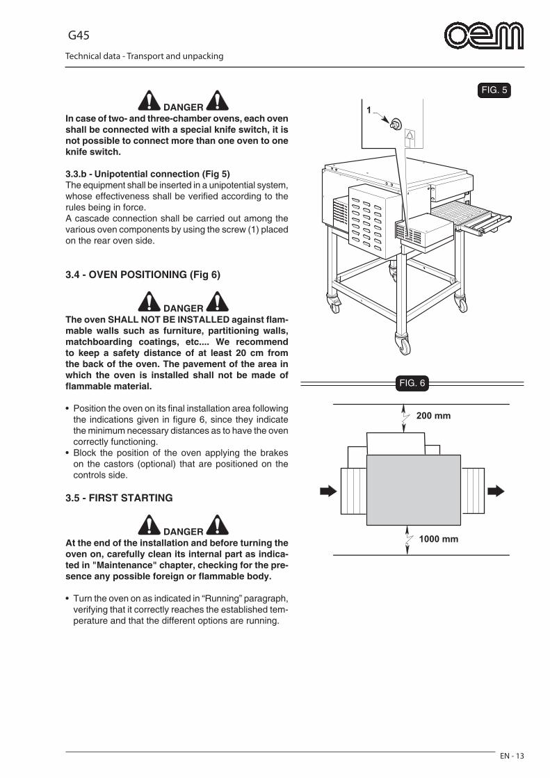
3.3.b - Unipotential connection (Fig 5)The equipment shall be inserted in a unipotential system, whose effectiveness shall be verifi ed according to the rules being in force.A cascade connection shall be carried out among the various oven components by using the screw (1) placed on the rear oven side.
3.4 - OVEN POSITIONING (Fig 6)
DANGER The oven SHALL NOT BE INSTALLED against fl am-mable walls such as furniture, partitioning walls, matchboarding coatings, etc.... We recommend to keep a safety distance of at least 20 cm from the back of the oven. The pavement of the area in which the oven is installed shall not be made of fl ammable material.
• Position the oven on its fi nal installation area following the indications given in fi gure 6, since they indicate the minimum necessary distances as to have the oven correctly functioning.
• Block the position of the oven applying the brakes on the castors (optional) that are positioned on the controls side.
3.5 - FIRST STARTING
DANGER At the end of the installation and before turning the oven on, carefully clean its internal part as indica-ted in "Maintenance" chapter, checking for the pre-sence any possible foreign or fl ammable body.
• Turn the oven on as indicated in “Running” paragraph, verifying that it correctly reaches the established tem-perature and that the different options are running.
G45
Installation and connections
EN - 14
FIG. 7
FIG. 8
FIG. 9
4
2
3
1
45
3
2
1
5
2
13
FIG. 10
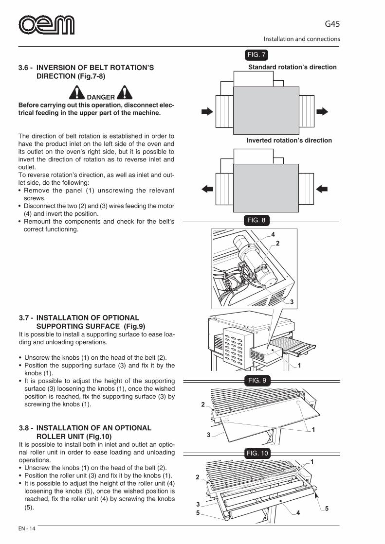
3.6 - INVERSION OF BELT ROTATION’S DIRECTION (Fig.7-8)
DANGER Before carrying out this operation, disconnect elec-trical feeding in the upper part of the machine.
The direction of belt rotation is established in order to have the product inlet on the left side of the oven and its outlet on the oven’s right side, but it is possible to invert the direction of rotation as to reverse inlet and outlet.To reverse rotation’s direction, as well as inlet and out-let side, do the following:• Remove the panel (1) unscrewing the relevant
screws.• Disconnect the two (2) and (3) wires feeding the motor
(4) and invert the position.• Remount the components and check for the belt’s
correct functioning.
Standard rotation’s direction
Inverted rotation’s direction
3.7 - INSTALLATION OF OPTIONAL SUPPORTING SURFACE (Fig.9)It is possible to install a supporting surface to ease loa-ding and unloading operations.
• Unscrew the knobs (1) on the head of the belt (2).• Position the supporting surface (3) and fi x it by the
knobs (1).• It is possible to adjust the height of the supporting
surface (3) loosening the knobs (1), once the wished position is reached, fi x the supporting surface (3) by screwing the knobs (1).
3.8 - INSTALLATION OF AN OPTIONAL ROLLER UNIT (Fig.10)It is possible to install both in inlet and outlet an optio-nal roller unit in order to ease loading and unloading operations.• Unscrew the knobs (1) on the head of the belt (2).• Position the roller unit (3) and fi x it by the knobs (1).• It is possible to adjust the height of the roller unit (4)
loosening the knobs (5), once the wished position is reached, fi x the roller unit (4) by screwing the knobs (5).
G45
EN - 15
Safety devices
FIG. 14.1 - EXPECTED USE
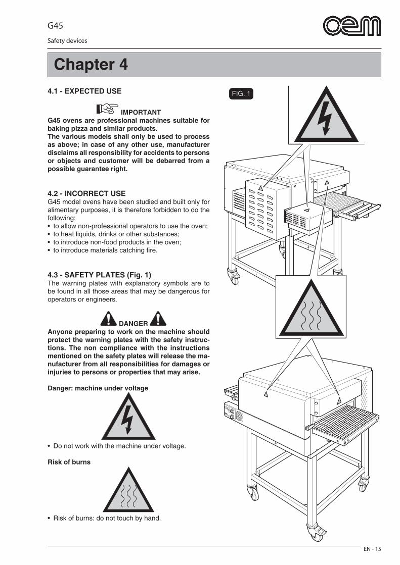
IMPORTANTG45 ovens are professional machines suitable for baking pizza and similar products.The various models shall only be used to process as above; in case of any other use, manufacturer disclaims all responsibility for accidents to persons or objects and customer will be debarred from a possible guarantee right.
4.2 - INCORRECT USEG45 model ovens have been studied and built only for alimentary purposes, it is therefore forbidden to do the following:• to allow non-professional operators to use the oven;• to heat liquids, drinks or other substances;• to introduce non-food products in the oven;• to introduce materials catching fi re.
4.3 - SAFETY PLATES (Fig. 1)The warning plates with explanatory symbols are to be found in all those areas that may be dangerous for operators or engineers.
DANGER Anyone preparing to work on the machine should protect the warning plates with the safety instruc-tions. The non compliance with the instructions mentioned on the safety plates will release the ma-nufacturer from all responsibilities for damages or injuries to persons or properties that may arise.
Danger: machine under voltage
• Do not work with the machine under voltage.
Risk of burns
• Risk of burns: do not touch by hand.
Chapter 4
G45
EN - 16
Safety devices
FIG. 3
O
O
O
T
AA
B
A
2
1
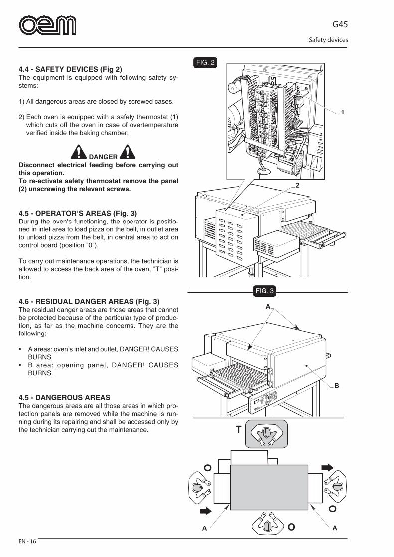
FIG. 24.4 - SAFETY DEVICES (Fig 2)The equipment is equipped with following safety sy-stems:
1) All dangerous areas are closed by screwed cases.
2) Each oven is equipped with a safety thermostat (1) which cuts off the oven in case of overtemperature verifi ed inside the baking chamber;
DANGER Disconnect electrical feeding before carrying out this operation.To re-activate safety thermostat remove the panel (2) unscrewing the relevant screws.
4.5 - OPERATOR’S AREAS (Fig. 3)During the oven’s functioning, the operator is positio-ned in inlet area to load pizza on the belt, in outlet area to unload pizza from the belt, in central area to act on control board (position "0").
To carry out maintenance operations, the technician is allowed to access the back area of the oven, "T" posi-tion.
4.6 - RESIDUAL DANGER AREAS (Fig. 3)The residual danger areas are those areas that cannot be protected because of the particular type of produc-tion, as far as the machine concerns. They are the following:
• A areas: oven’s inlet and outlet, DANGER! CAUSES BURNS
• B area: opening panel, DANGER! CAUSES BURNS.
4.5 - DANGEROUS AREASThe dangerous areas are all those areas in which pro-tection panels are removed while the machine is run-ning during its repairing and shall be accessed only by the technician carrying out the maintenance.
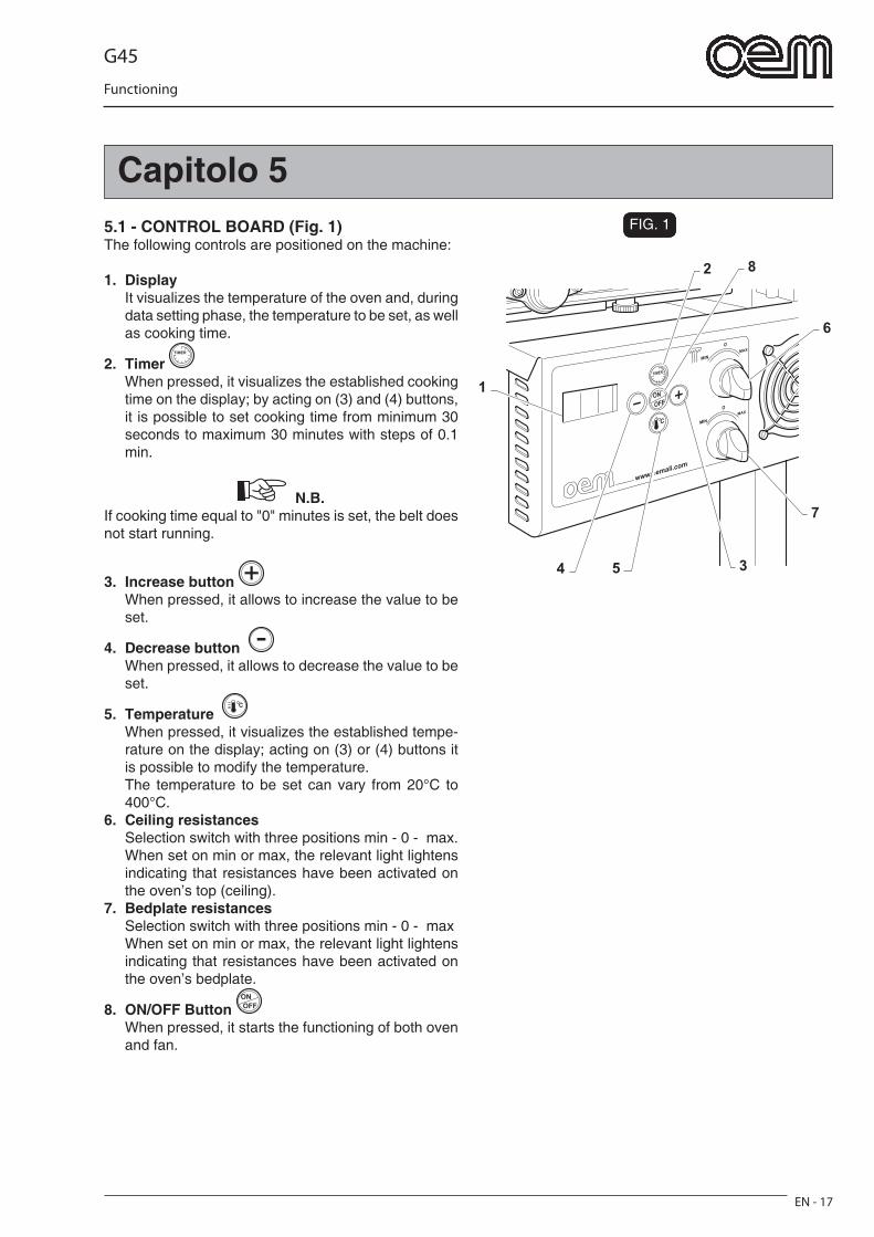
G45
Functioning
EN - 17
Capitolo 5FIG. 1
2
6
7
54 3
8
1
5.1 - CONTROL BOARD (Fig. 1)The following controls are positioned on the machine:
1. Display It visualizes the temperature of the oven and, during
data setting phase, the temperature to be set, as well as cooking time.
2. Timer When pressed, it visualizes the established cooking
time on the display; by acting on (3) and (4) buttons, it is possible to set cooking time from minimum 30 seconds to maximum 30 minutes with steps of 0.1 min.
N.B. If cooking time equal to "0" minutes is set, the belt does not start running.
3. Increase button When pressed, it allows to increase the value to be
set.
4. Decrease button When pressed, it allows to decrease the value to be
set.
5. Temperature When pressed, it visualizes the established tempe-
rature on the display; acting on (3) or (4) buttons it is possible to modify the temperature.
The temperature to be set can vary from 20°C to 400°C.
6. Ceiling resistances Selection switch with three positions min - 0 - max. When set on min or max, the relevant light lightens
indicating that resistances have been activated on the oven’s top (ceiling).
7. Bedplate resistances Selection switch with three positions min - 0 - max When set on min or max, the relevant light lightens
indicating that resistances have been activated on the oven’s bedplate.
8. ON/OFF Button When pressed, it starts the functioning of both oven
and fan.
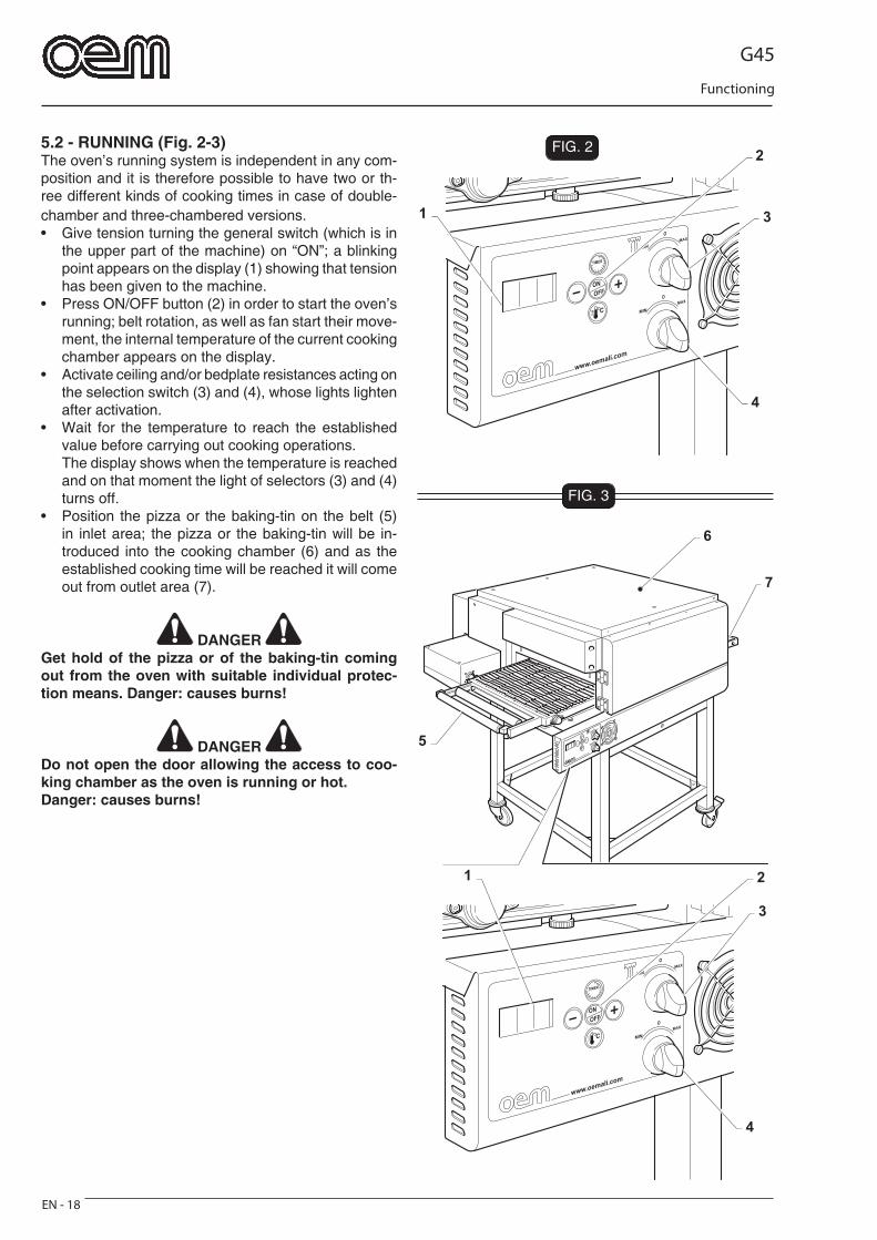
G45
Functioning
EN - 18
FIG. 2
3
4
21
7
6
5
FIG. 3
3
4
2
1
5.2 - RUNNING (Fig. 2-3)The oven’s running system is independent in any com-position and it is therefore possible to have two or th-ree different kinds of cooking times in case of double-chamber and three-chambered versions.• Give tension turning the general switch (which is in
the upper part of the machine) on “ON”; a blinking point appears on the display (1) showing that tension has been given to the machine.
• Press ON/OFF button (2) in order to start the oven’s running; belt rotation, as well as fan start their move-ment, the internal temperature of the current cooking chamber appears on the display.
• Activate ceiling and/or bedplate resistances acting on the selection switch (3) and (4), whose lights lighten after activation.
• Wait for the temperature to reach the established value before carrying out cooking operations.
The display shows when the temperature is reached and on that moment the light of selectors (3) and (4) turns off.
• Position the pizza or the baking-tin on the belt (5) in inlet area; the pizza or the baking-tin will be in-troduced into the cooking chamber (6) and as the established cooking time will be reached it will come out from outlet area (7).
DANGER Get hold of the pizza or of the baking-tin coming out from the oven with suitable individual protec-tion means. Danger: causes burns!
DANGER Do not open the door allowing the access to coo-king chamber as the oven is running or hot.Danger: causes burns!

G45
Functioning
EN - 19
FIG. 4
1
6
7
53 2
4
1
2
FIG. 5
5.3 - SETTINGS MODIFICATION (Fig.4)According to the user’s experience, to the kind of mixtu-re and to the kind of product to be cooked it is possible to modify the machine’s settings.The parameters that can be set are the following:• Cooking time, which corresponds to the belt’s shif-
ting, namely to the time the pizza or the product to be cooked remains inside the cooking chamber.
To set cooking time press button (1) and act on (2) and (3) buttons to increase or decrease time; established time is shown on the display (4).
• The temperature To set the temperature press button (5) and act on (2)
and (3) buttons to increase or decrease; established temperature is shown on the display (4).
It is also possible to increase or decrease cooking in the lower or upper part of the oven by acting on selec-tion switches (6) or (7), for example by setting ceiling selection switch on Min and bedplate one on Max.
IMPORTANTCarry out some cooking tests to fi nd the correct para-meters.
5.4 - ADJUSTMENT OF THE OVEN’S OPENING HEIGHT (Fig.5)
DANGER The adjustment shall be carried out as the machine has been turned off and as it is cold.Danger: causes burns!
To increase the oven’s performance, it is possible to adjust inlet and outlet opening’s height; we suggest to adjust the sheet (1) at 1-2 cm above the product inser-ted into the oven.To carry out the adjustment, loosen the knobs (2); as the adjustment has been completed, screw the knobs (2).
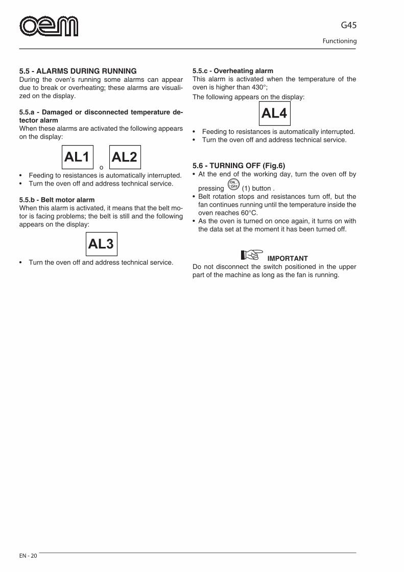
G45
Functioning
EN - 20
5.5 - ALARMS DURING RUNNINGDuring the oven’s running some alarms can appear due to break or overheating; these alarms are visuali-zed on the display. 5.5.a - Damaged or disconnected temperature de-tector alarmWhen these alarms are activated the following appears on the display:
o • Feeding to resistances is automatically interrupted.• Turn the oven off and address technical service.
5.5.b - Belt motor alarmWhen this alarm is activated, it means that the belt mo-tor is facing problems; the belt is still and the following appears on the display:
AL3
• Turn the oven off and address technical service.
5.5.c - Overheating alarmThis alarm is activated when the temperature of the oven is higher than 430°;The following appears on the display:
AL4
• Feeding to resistances is automatically interrupted.• Turn the oven off and address technical service.
5.6 - TURNING OFF (Fig.6)• At the end of the working day, turn the oven off by
pressing (1) button .• Belt rotation stops and resistances turn off, but the
fan continues running until the temperature inside the oven reaches 60°C.
• As the oven is turned on once again, it turns on with the data set at the moment it has been turned off.
IMPORTANT Do not disconnect the switch positioned in the upper part of the machine as long as the fan is running.
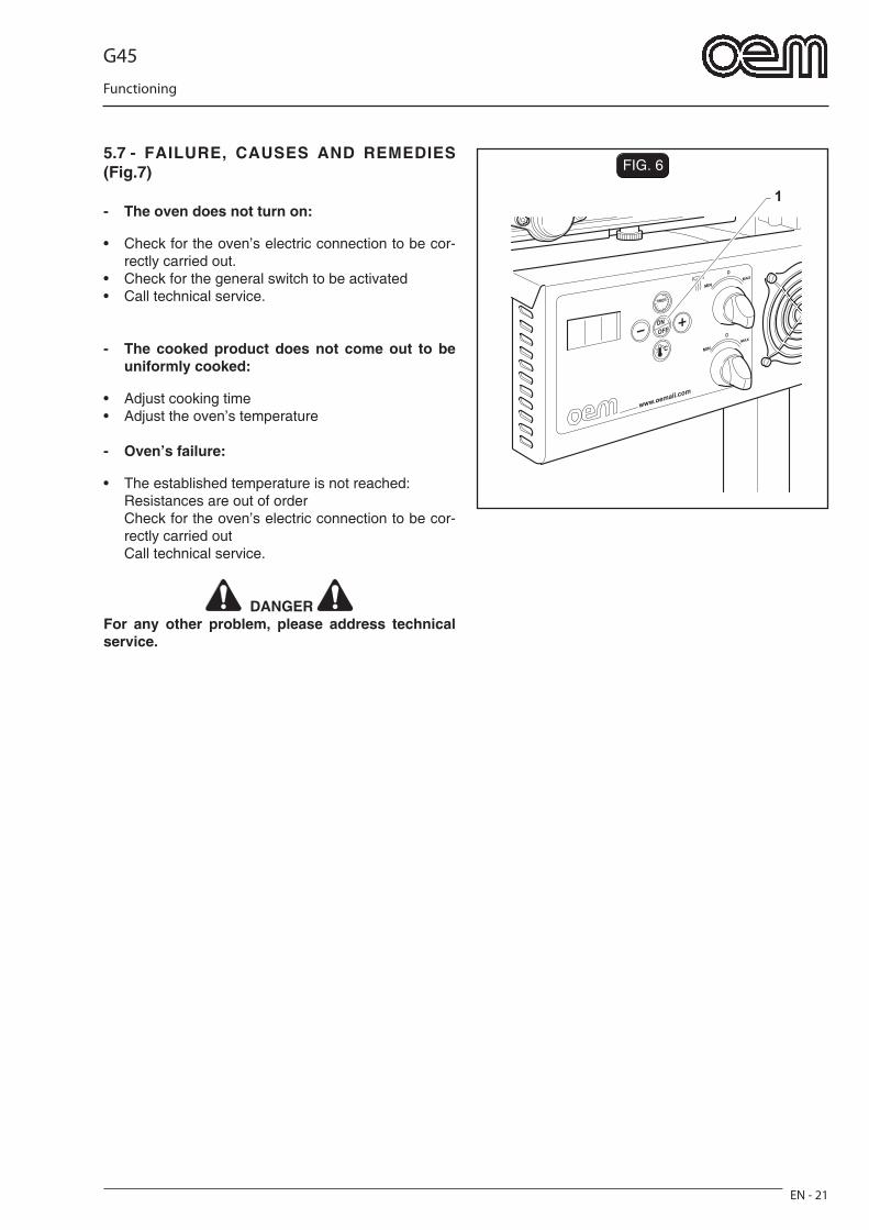
G45
Functioning
EN - 21
FIG. 6
1
5.7 - FAILURE, CAUSES AND REMEDIES (Fig.7)
- The oven does not turn on:
• Check for the oven’s electric connection to be cor-rectly carried out.
• Check for the general switch to be activated • Call technical service.
- The cooked product does not come out to be uniformly cooked:
• Adjust cooking time • Adjust the oven’s temperature
- Oven’s failure:
• The established temperature is not reached: Resistances are out of order Check for the oven’s electric connection to be cor-
rectly carried out Call technical service.
DANGER For any other problem, please address technical service.
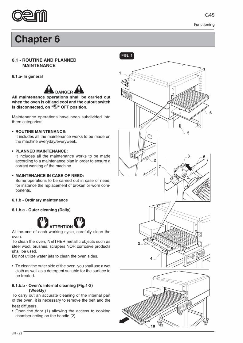
G45
Functioning
EN - 22
1
6
3
4
8 9
7
10
2
5
FIG. 1
Chapter 6
6.1 - ROUTINE AND PLANNED MAINTENANCE
6.1.a- In general
DANGER All maintenance operations shall be carried out when the oven is off and cool and the cutout switch is disconnected, on " " OFF position.
Maintenance operations have been subdivided into three categories:
• ROUTINE MAINTENANCE:It includes all the maintenance works to be made on the machine everyday/everyweek.
• PLANNED MAINTENANCE:It includes all the maintenance works to be made according to a maintenance plan in order to ensure a correct working of the machine.
• MAINTENANCE IN CASE OF NEED:Some operations to be carried out in case of need, for instance the replacement of broken or worn com-ponents.
6.1.b - Ordinary maintenance
6.1.b.a - Outer cleaning (Daily)
ATTENTION At the end of each working cycle, carefully clean the oven.To clean the oven, NEITHER metallic objects such as steel wool, brushes, scrapers NOR corrosive products shall be used.Do not utilize water jets to clean the oven sides.
• To clean the outer side of the oven, you shall use a wet cloth as well as a detergent suitable for the surface to be treated.
6.1.b.b - Oven’s internal cleaning (Fig.1-2) (Weekly)To carry out an accurate cleaning of the internal part of the oven, it is necessary to remove the belt and the heat diffusers.• Open the door (1) allowing the access to cooking
chamber acting on the handle (2).
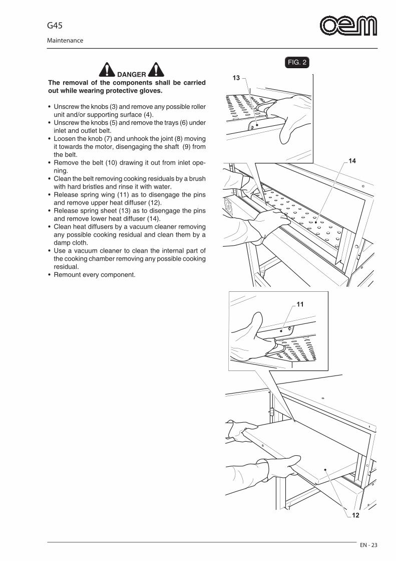
G45
Maintenance
EN - 23
FIG. 2
12
11
14
13 DANGER
The removal of the components shall be carried out while wearing protective gloves.
• Unscrew the knobs (3) and remove any possible roller unit and/or supporting surface (4).
• Unscrew the knobs (5) and remove the trays (6) under inlet and outlet belt.
• Loosen the knob (7) and unhook the joint (8) moving it towards the motor, disengaging the shaft (9) from the belt.
• Remove the belt (10) drawing it out from inlet ope-ning.
• Clean the belt removing cooking residuals by a brush with hard bristles and rinse it with water.
• Release spring wing (11) as to disengage the pins and remove upper heat diffuser (12).
• Release spring sheet (13) as to disengage the pins and remove lower heat diffuser (14).
• Clean heat diffusers by a vacuum cleaner removing any possible cooking residual and clean them by a damp cloth.
• Use a vacuum cleaner to clean the internal part of the cooking chamber removing any possible cooking residual.
• Remount every component.
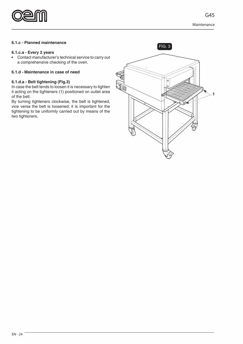
G45
Maintenance
EN - 24
FIG. 3
1
6.1.c - Planned maintenance
6.1.c.a - Every 2 years• Contact manufacturer’s technical service to carry out
a comprehensive checking of the oven.
6.1.d - Maintenance in case of need
6.1.d.a - Belt tightening (Fig.3)In case the belt tends to loosen it is necessary to tighten it acting on the tighteners (1) positioned on outlet area of the belt.By turning tighteners clockwise, the belt is tightened, vice versa the belt is loosened; it is important for the tightening to be uniformly carried out by means of the two tighteners.
G45
Dismantling - Demolition - Disposal
EN - 25
Chapter 7
7.1 - DISMANTLING THE MACHINEProceed by complying with the instructions given in the “Installation” chapter, working in reverse order, if the machine must be dismantled and then moved to another site.
DANGER Before disassembling the machine or demounting some machine components, disconnect the power supply.
The machine assembling shall only be carried out by skilled and authorized personnel.
ATTENTION In case it is necessary to disassemble the machine or demount some machine components in a diffe-rent way in comparison with the written instruc-tions, Company manufacturer or its Agent shall be contacted - see addresses on the third page of this publication.
7.2 - DEMOLISHING THE MACHINE
To protect the environment, please proceed in compliance with the local laws in force.When the machine can no longer be used or repaired, please proceed with recycle and disposal.
Electrical equipment cannot be disposed of as ordi-nary urban waste: it must be disposed of according to the special EU directive for the recycling of electric and electronic equipment.The electrical equipment is marked with a pictogram of a garbage can inside a barred circle. This symbol means that the equipment was sold on the market after August 13, 2005, and must be disposed of accordingly.Due to the substances and materials it contains, inappropriate or illegal disposal of this equipment, or improper use of the same, can be harmful to humans and the environment. Improper disposal of electric equipment that fails to respect the laws in force will be subject to administrative fi nes and penal sanctions.
ATTENTION Consult the next paragraph when disposing of harmful materials (lubricants, solvents, coating products, etc.).
7.3 - DISPOSING OF HARMFUL SUBSTANCESConsult the provisions established by the Standards in force in each individual country before disposing of such substances.
ATTENTION Any improper use by the Customer before, during or after scrapping and disposing of the parts of the machine, in respect of the construction and application of the applicable regulations, shall be the customer’s responsibility.

G45
Wiring diagram
EN - 26
220 SINGLE-PHASE MOTOR WIRING DIAGRAM
230/1-N FEEDING
TE
MP
ER
AT
UR
E
DE
TE
CT
OR
BROWN BROWN
MO
TO
R T
HE
RM
IC
RE
LAY
EN
CO
DE
R
MO
T. M
1
BE
LT
MO
TO
R
SA
FE
TY
TH
ER
MO
ST
AT
CE
ILING
BE
DP
LAT
E
RED
BLACK
BROWN
RED
BLACK
WHITE
BLUE
OV
EN
’S F
AN
MO
TO
R
RE
D+
WH
ITE
BLA
CKC
ON
TR
OL
BO
AR
D F
AN
BLU
E
SW
ITC
HB
OA
RD
F
AN
CE
ILING
BE
DP
LAT
E
PH
AS
E
NE
UTR
AL
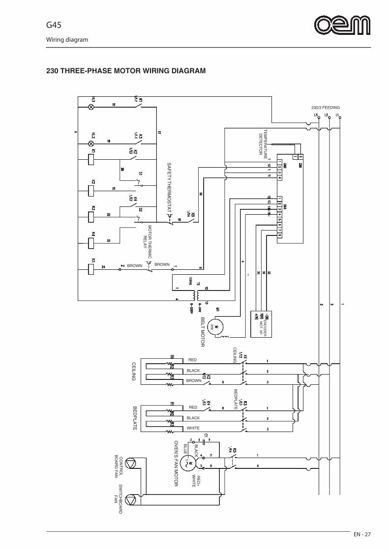
G45
Wiring diagram
EN - 27
230 THREE-PHASE MOTOR WIRING DIAGRAM
230/3 FEEDING
TE
MP
ER
AT
UR
E
DE
TE
CT
OR
BROWN BROWN
MO
TO
R T
HE
RM
IC
RE
LAY
EN
CO
DE
R
MO
T. M
1
BE
LT M
OT
OR
SA
FE
TY
TH
ER
MO
ST
AT
CE
ILING
BE
DP
LAT
E
RED
BLACK
BROWN
RED
BLACK
WHITE
OV
EN
’S F
AN
MO
TO
R
RE
D+
WH
ITE
BLA
CKC
ON
TR
OL
BO
AR
D F
AN
BLU
E
SW
ITC
HB
OA
RD
F
AN
CE
ILING
BE
DP
LAT
E

G45
Wiring diagram
EN - 28
400 THREE-PHASE MOTOR WIRING DIAGRAM
400/3-N FEEDING
TE
MP
ER
AT
UR
E
DE
TE
CT
OR
BROWN BROWN
MO
TO
R T
HE
RM
IC
RE
LAY
EN
CO
DE
R
MO
T. M
1
BE
LT M
OT
OR
SA
FE
TY
TH
ER
MO
ST
AT
CE
ILING
BE
DP
LAT
E
RED
BLACK
BROWN
RED
BLACK
WHITE
BLUE
OV
EN
’S F
AN
MO
TO
R
RE
D+
WH
ITE
BLA
CKC
ON
TR
OL
BO
AR
D F
AN
BLU
E
SW
ITC
HB
OA
RD
F
AN
CE
ILING
BE
DP
LAT
E
BLUE
G45
Wiring diagram
EN - 29
LEGENDA
K1 = Ceiling resistance main remote control switchK2 = Ceiling resistance economy remote control switchK3 = Bedplate resistance main remote control switchK4 = Bedplate resistance economy remote control switchK5 = Oven’s fan remote control switchHL1 = Lamp signalling ceiling resistance activatedHL2 = Lamp signalling bedplate resistance activatedS1 = Ceiling resistance selection switch S2 = Bedplate resistance selection switchT1 = Transformer 0-230/0-24V for control board feeding
G45
FR - 1
Normes et instructions générales
FRANÇAIS
CHAPITRE ........................................................1Chapitre destinée au technicien et à l’opérateur1.1 INSTRUCTIONS GENERALES .........................Pag. FR-31.2 REFERENCES NORMATIVES .........................Pag. FR-41.3 COMPOSITION DE LA MACHINE ....................Pag. FR-41.4 DESCRIPTION DES SYMBOLES .....................Pag. FR-41.5 ADAPTATIONS A LA CHARGE DE L’ACHETEUR .................................................. Pag. FR-51.6 OPERATIONS D’URGENCE EN CAS D’INCENDIE .................................................... Pag. FR-51.7 RISQUE D’EXPLOSION ....................................Pag. FR-51.8 NIVEAU DE PRESSION ACOUSTIQUE .........Pag. FR-5
CHAPITRE ........................................................2Chapitre destinée au technicien- DIMENSIONS ............................................................Pag. FR-62.1 CARACTERISTIQUES TECHNIQUES ...........Pag. FR-72.2 TRANSPORT ......................................................Pag. FR-8 2.2.a Expedition ...................................................Pag. FR-8 2.2.b Soulevement emballage............................Pag. FR-8 2.2.c Stockage .....................................................Pag. FR-82.3 CONTROLE A LA RECEPTION ........................Pag. FR-92.4 DESEMBALLAGE ...............................................Pag. FR-92.5 IDENTIFICATION DES COMPOSANTS ........Pag. FR-102.6 IDENTIFICATION DE LA MACHINE ...............Pag. FR-10
CHAPITRE ........................................................3Chapitre destinée au technicien3.1 SOULEVEMENT MACHINE ............................Pag. FR-113.2 ASSEMBLAGE DES COMPOSANTS ...........Pag. FR-113.3 BRANCHEMENT ELECTRIQUE ....................Pag. FR-12 3.3.a Branchement électrique du four..............Pag. FR-12 3.3.b Branchement équipotentiel .....................Pag. FR-133.4 POSITIONNEMENT DU FOUR .......................Pag. FR-133.5 DEMARRAGE DANGER ..................................Pag. FR-133.6 INVERSION DU SENS DE ROTATION DE LA BANDE ..................................................Pag. FR-143.7 INSTALLATION DU PLAN D’APPUI OPTIONNEL .....................................................Pag. FR-143.8 INSTALLATION TRANSPORTEUR A ROULEAUX OPTIONNEL ................................Pag. FR-14
CHAPITRE ........................................................4Chapitre destinée au technicien et à l’opérateur4.1 EMPLOI PREVU ...............................................Pag. FR-154.2 EMPLOI INCORRECT ....................................Pag. FR-154.3 PLAQUETTES DE SECURITE ........................Pag. FR-154.4 SECURITE ........................................................Pag. FR-164.5 ZONES OPERATEUR ......................................Pag. FR-164.6 ZONE A DANGER RESIDU .............................Pag. FR-164.7 ZONES DANGEREUSES ................................Pag. FR-16
CHAPITRE ........................................................5Chapitre destinée au technicien et à l’opérateur5.1 PANNEAU DE CONTROLE .............................Pag. FR-175.2 FONCTIONNEMENT ........................................Pag. FR-185.3 MODIFICATION DES AFFICHAGES ..............Pag. FR-195.4 REGLAGE HAUTEUR OUVERTURE .............Pag. FR-195.5 ALARMES PENDANT LE FONCTIONNEMENT ....Pag. FR-20 5.5.a Alarme sonde température endommagée ou débranchée ...............Pag. FR-20 5.5.b Alarme moteur bande ..............................Pag. FR-20 5.5.c Alarme température du four excessive .........Pag. FR-205.6 ARRET ...............................................................Pag. FR-205.7 MAUVAIS FONCTIONNEMENT, CAUSES ET REMEDES ..................................Pag. FR-21
CHAPITRE ........................................................6Chapitre destinée au technicien et à l’opérateur6.1 ENTRETIEN ORDINAIRE ET PROGRAMME ..................................................Pag. FR-22 6.1.a Generalité ...............................................Pag. FR-22 6.1.b Interventions d’entretien ordinaire ........Pag. FR-22 6.1.b - a Nettoyage externe ............................Pag. FR-22 6.1.b - b Nettoyage interne du four ...............Pag. FR-22 6.1.c Interventions d'entretien programme ....Pag. FR-24 6.1.c - a Tous les 2 ans ..................................Pag. FR-24 6.1.d Interventions d'entretien d'apres necessite ................................................Pag. FR-24 6.1.d - a Tension de la bande .........................Pag. FR-24
CHAPITRE ........................................................7Chapitre destinée au technicien7.1 DEMONTAGE DE LA MACHINE ....................Pag. FR-257.2 DEMANTELEMENT DE LA MACHINE ...........Pag. FR-257.3 ELIMINATION DES SUBSTANCES NOCIVES ..........................................................Pag. FR-25
SCHEMA ELECTRIQUE 220 MONOPHASE ........Pag. FR-26SCHEMA ELECTRIQUE 230 TRIPHASE ..............Pag. FR-27SCHEMA ELECTRIQUE 400 TRIPHASE ..............Pag. FR-28
LEGENDA ................................................................Pag. FR-29

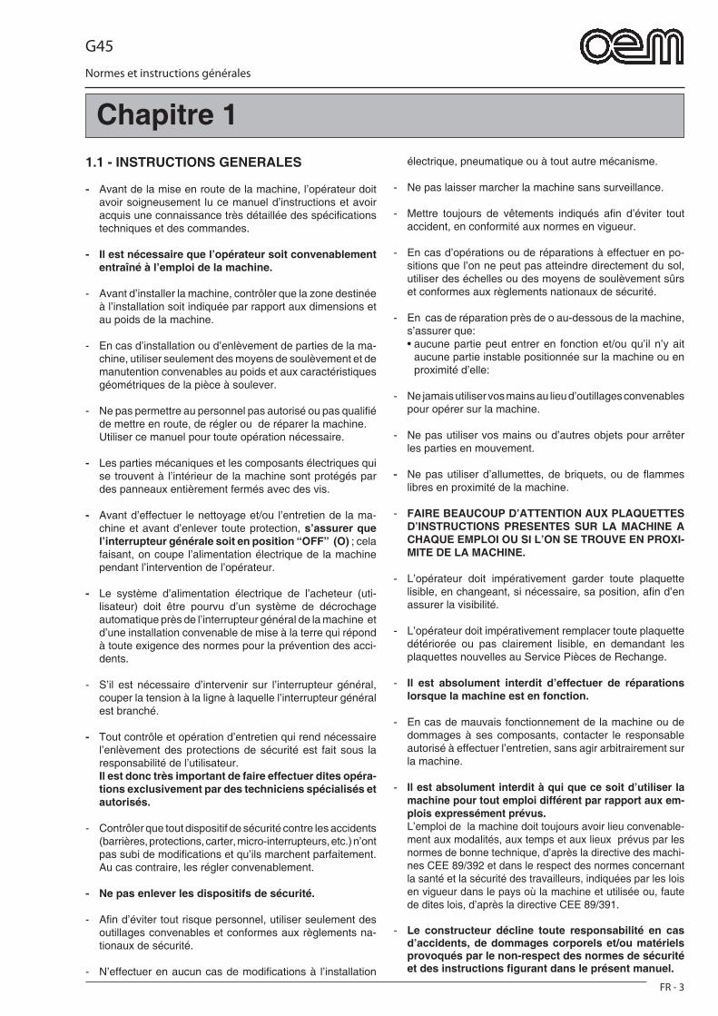
G45
FR - 3
Normes et instructions générales
Chapitre 11.1 - INSTRUCTIONS GENERALES
- Avant de la mise en route de la machine, l’opérateur doit avoir soigneusement lu ce manuel d’instructions et avoir acquis une connaissance très détaillée des spécifi cations techniques et des commandes.
- Il est nécessaire que l’opérateur soit convenablement entraîné à l’emploi de la machine.
- Avant d’installer la machine, contrôler que la zone destinée à l’installation soit indiquée par rapport aux dimensions et au poids de la machine.
- En cas d’installation ou d’enlèvement de parties de la ma-chine, utiliser seulement des moyens de soulèvement et de manutention convenables au poids et aux caractéristiques géométriques de la pièce à soulever.
- Ne pas permettre au personnel pas autorisé ou pas qualifi é de mettre en route, de régler ou de réparer la machine.
Utiliser ce manuel pour toute opération nécessaire.
- Les parties mécaniques et les composants électriques qui se trouvent à l’intérieur de la machine sont protégés par des panneaux entièrement fermés avec des vis.
- Avant d’effectuer le nettoyage et/ou l’entretien de la ma-chine et avant d’enlever toute protection, s’assurer que l’interrupteur générale soit en position “OFF” (O) ; cela faisant, on coupe l’alimentation électrique de la machine pendant l’intervention de l’opérateur.
- Le système d’alimentation électrique de l’acheteur (uti-lisateur) doit être pourvu d’un système de décrochage automatique près de l’interrupteur général de la machine et d’une installation convenable de mise à la terre qui répond à toute exigence des normes pour la prévention des acci-dents.
- S’il est nécessaire d’intervenir sur l’interrupteur général, couper la tension à la ligne à laquelle l’interrupteur général est branché.
- Tout contrôle et opération d’entretien qui rend nécessaire l’enlèvement des protections de sécurité est fait sous la responsabilité de l’utilisateur.
Il est donc très important de faire effectuer dites opéra-tions exclusivement par des techniciens spécialisés et autorisés.
- Contrôler que tout dispositif de sécurité contre les accidents (barrières, protections, carter, micro-interrupteurs, etc.) n’ont pas subi de modifi cations et qu’ils marchent parfaitement. Au cas contraire, les régler convenablement.
- Ne pas enlever les dispositifs de sécurité.
- Afi n d’éviter tout risque personnel, utiliser seulement des outillages convenables et conformes aux règlements na-tionaux de sécurité.
- N’effectuer en aucun cas de modifi cations à l’installation
électrique, pneumatique ou à tout autre mécanisme.
- Ne pas laisser marcher la machine sans surveillance.
- Mettre toujours de vêtements indiqués afi n d’éviter tout accident, en conformité aux normes en vigueur.
- En cas d’opérations ou de réparations à effectuer en po-sitions que l’on ne peut pas atteindre directement du sol, utiliser des échelles ou des moyens de soulèvement sûrs et conformes aux règlements nationaux de sécurité.
- En cas de réparation près de o au-dessous de la machine, s’assurer que:
• aucune partie peut entrer en fonction et/ou qu’il n’y ait aucune partie instable positionnée sur la machine ou en proximité d’elle:
- Ne jamais utiliser vos mains au lieu d’outillages convenables pour opérer sur la machine.
- Ne pas utiliser vos mains ou d’autres objets pour arrêter les parties en mouvement.
- Ne pas utiliser d’allumettes, de briquets, ou de fl ammes libres en proximité de la machine.
- FAIRE BEAUCOUP D’ATTENTION AUX PLAQUETTES D’INSTRUCTIONS PRESENTES SUR LA MACHINE A CHAQUE EMPLOI OU SI L’ON SE TROUVE EN PROXI-MITE DE LA MACHINE.
- L’opérateur doit impérativement garder toute plaquette lisible, en changeant, si nécessaire, sa position, afi n d’en assurer la visibilité.
- L’opérateur doit impérativement remplacer toute plaquette détériorée ou pas clairement lisible, en demandant les plaquettes nouvelles au Service Pièces de Rechange.
- Il est absolument interdit d’effectuer de réparations lorsque la machine est en fonction.
- En cas de mauvais fonctionnement de la machine ou de dommages à ses composants, contacter le responsable autorisé à effectuer l’entretien, sans agir arbitrairement sur la machine.
- Il est absolument interdit à qui que ce soit d’utiliser la machine pour tout emploi différent par rapport aux em-plois expressément prévus.
L’emploi de la machine doit toujours avoir lieu convenable-ment aux modalités, aux temps et aux lieux prévus par les normes de bonne technique, d’après la directive des machi-nes CEE 89/392 et dans le respect des normes concernant la santé et la sécurité des travailleurs, indiquées par les lois en vigueur dans le pays où la machine et utilisée ou, faute de dites lois, d’après la directive CEE 89/391.
- Le constructeur décline toute responsabilité en cas d’accidents, de dommages corporels et/ou matériels provoqués par le non-respect des normes de sécurité et des instructions fi gurant dans le présent manuel.
G45
FR - 4
Normes et instructions générales
- LES NORMES DE SECURITE INDIQUEES DANS CE MANUEL INTEGRENT OU COMPENSENT LES NORMES DE SECURITE EN VIGUEUR LOCALEMENT.
- Ne JAMAIS effectuer de réparations hâtives ou de fortune qui pourraient compromettre le bon fonctionnement de la machine et la sécurité de l’opérateur.
- EN CAS DE DOUTE DEMANDER TOUJOURS L’INTER-VENTION DE PERSONNEL SPECIALISE.
- TOUTE MODIFICATION, ELECTRIQUE/ELECTRONIQUE OU MECANIQUE DE LA MACHINE DE LA PART DE L’UTILISATEUR ET TOUT EMPLOI DE LA MACHINE AVEC NEGLIGENCE, SOULEVENT LA SOCIETE PRO-DUCTRICE DE TOUTE RESPONSABILITE ET REND L’UTILISATEUR LE SEUL RESPONSABLE A L’EGARD DES ORGANES COMPETENTS POUR LA PREVENTION DES ACCIDENTS.
1.2 - REFERENCES NORMATIVES- La machine et ses dispositifs de sécurité ont été
produits en conformité aux normes indiquées dans la déclaration de conformité.
1.3 - DESCRIPTION DES SYMBOLESBeaucoup d’accidents sont causés par une con-naissance insuffi sante des instructions et par faute d’application des règles de sécurité à appliquer pen-dant le fonctionnement et les opérations d’entretien de la machine.Afi n d’éviter tout accident, lire, bien comprendre et suivre toute instruction contenue dans ce manuel et sur les plaquettes appliquées sur la machine.Pour identifi er les messages de sécurité insérés dans ce manuel on a utilisé les symboles suivants:
DANGERCe symbole est utilisé dans les messages de sé-curité du manuel, lorsqu’ils existent de situations de danger ou des possibilités de lésion sérieuse ou de mort.
ATTENTIONCe symbole est utilisé dans les messages de sé-curité du manuel pour de dangers qui, si négligés, peuvent provoquer de lésions ou dommages petits ou modérés.Le message peut être utilisé même seulement pour dangers qui peuvent provoquer de dommages à la machine.
IMPORTANTCe symbole est utilisé pour des précautions qu’il est nécessaire de prendre afi n d’éviter toute opération qui pourrait diminuer la durée de la machine ou bien pour toute communication importante pour l’opérateur.
DANGER
Pour clarté d’information, quelques illustrations de ce manuel montrent la machine sans protections. NE JAMAIS UTILISER LA MACHINE SANS PRO-TECTIONS.
1.4 - COMPOSITION DE LA MACHINELes machines de la société constructrice sont le fruit de l’expérience après d’années de travail.
• Les fours à convection peuvent être à une/deux/trois chambres; ils se composent d’une enveloppe en acier inox dûment isolée, d’une bande transporteuse en acier inox à chaînons fi ns et d’un système de cuisson à convection par des résistances.
Recirculation de l’air chaude à l’aide d’un ventila-teur.
• Le four ou les fours s’appuient sur une base portati-ve.
G45
FR - 5
Normes et instructions générales
1.5 - ADAPTATIONS A LA CHARGE DE L’ACHETEUR
a) Adaptation du lieu d’installation.• L’acheteur doit préparer une surface d’appui pour la
machine comme indiqué dans le chapitre d’installa-tion.
b) Adaptation du système électrique.• Le système électrique d’alimentation doit être con-
forme aux normes nationales en vigueur dans le lieu d’installation et pourvu d’une mise à la terre effi cace.
• Positionner un dispositif omni polaire de section-nement sur la ligne d’alimentation, dans la partie supérieure de la machine.
• Les câbles électriques d’alimentation doivent être dimensionnés en fonction du courant ma-ximum demandé par la machine ; cela faisant, la chute de tension totale, à plaine charge, résulte inférieure à 2%.
c) Gestion du neutre• L’équipement est pourvu de neutre donc une borne
identifi ée d’après les normatives spécifi ques a été prévue.
1.6 - OPERATIONS D’URGENCE EN CAS D’INCENDIE
a) En cas d’incendie couper la tension de la machine en débranchant l’interrupteur général.
b) Eteindre l’incendie en utilisant des extincteurs con-venables.
DANGER Lorsque la machine est sous tension, il est absolu-ment interdit de chercher d’étendre l’incendie par de l’eau.
1.7 - RISQUE D’EXPLOSION• L’emploi de la machine n’est pas indiqué dans des
environnements présentant de risques d’explosion.
1.8 - NIVEAU DE PRESSION ACOUSTIQUELes fours modèle GHIBLI G45 ont été étudiés pour garder le niveau de pression acoustique continu, équivalent et pondéré A(dB) au-dessous de la limite maximale admise di 70dB.
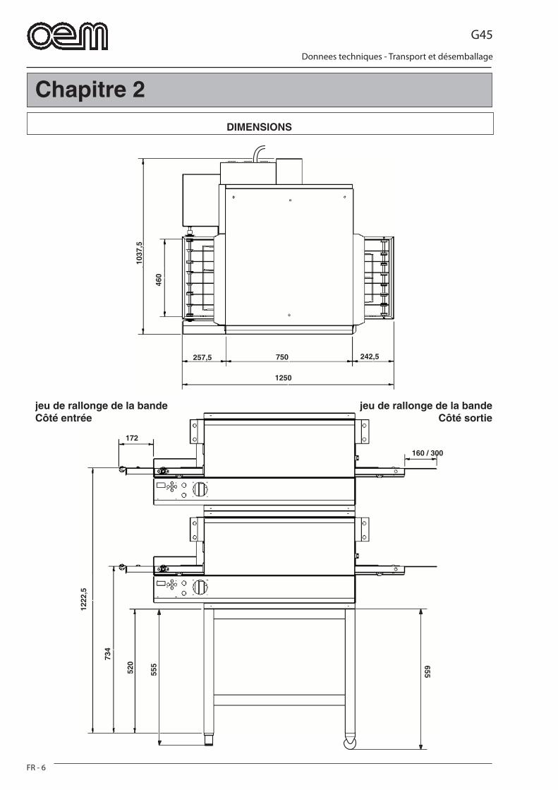
G45
FR - 6
Donnees techniques - Transport et désemballage
1037
,5
460
750
1250
257,5 242,5
1222
,5
734
520
555 655
160 / 300
172
Chapitre 2DIMENSIONS
jeu de rallonge de la bande Côté entrée
jeu de rallonge de la bande Côté sortie
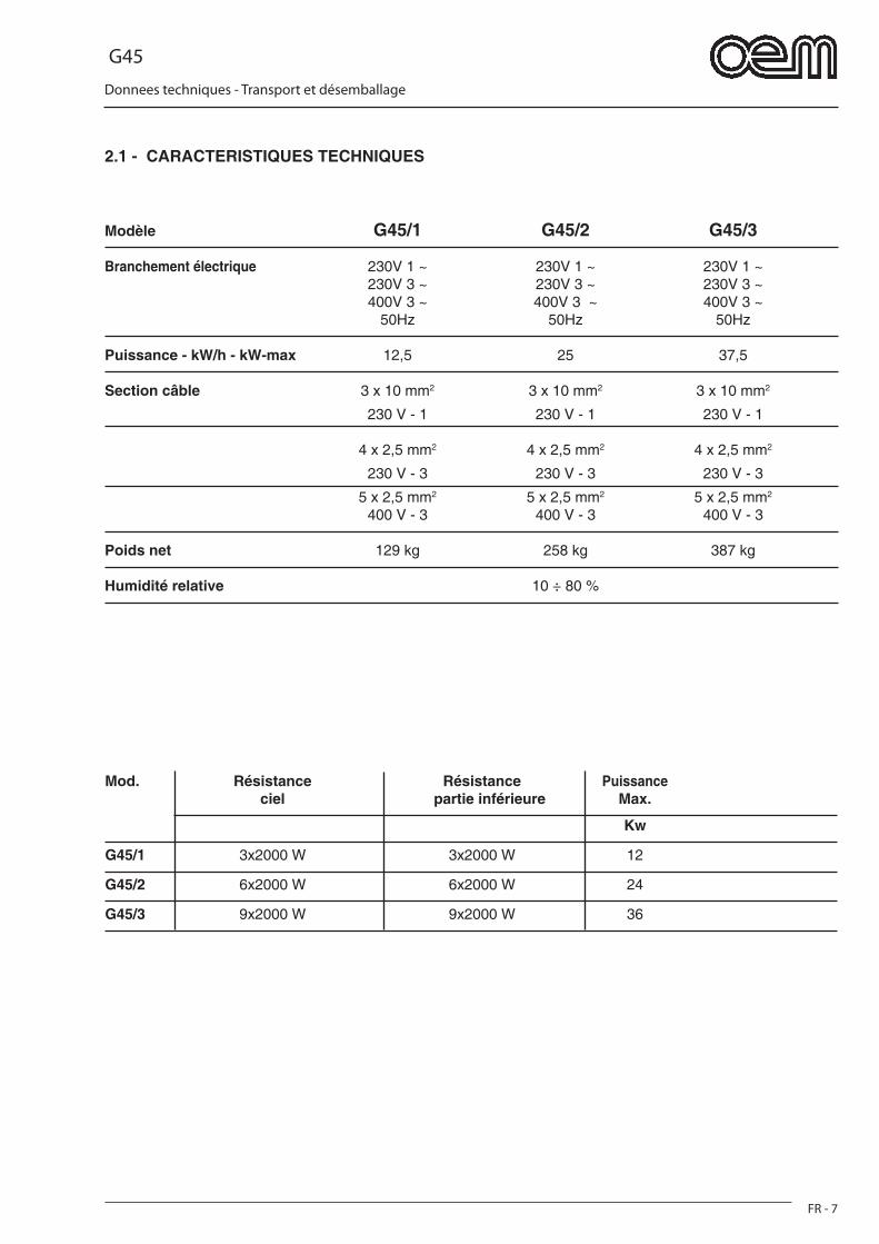
G45
FR - 7
Donnees techniques - Transport et désemballage
2.1 - CARACTERISTIQUES TECHNIQUES
Modèle G45/1 G45/2 G45/3
Branchement électrique 230V 1 ~ 230V 1 ~ 230V 1 ~ 230V 3 ~ 230V 3 ~ 230V 3 ~ 400V 3 ~ 400V 3 ~ 400V 3 ~ 50Hz 50Hz 50Hz
Puissance - kW/h - kW-max 12,5 25 37,5
Section câble 3 x 10 mm2 3 x 10 mm2 3 x 10 mm2
230 V - 1 230 V - 1 230 V - 1
4 x 2,5 mm2 4 x 2,5 mm2 4 x 2,5 mm2
230 V - 3 230 V - 3 230 V - 3
5 x 2,5 mm2 5 x 2,5 mm2 5 x 2,5 mm2
400 V - 3 400 V - 3 400 V - 3
Poids net 129 kg 258 kg 387 kg
Humidité relative 10 ÷ 80 %
Mod. Résistance Résistance Puissance ciel partie inférieure Max.
Kw
G45/1 3x2000 W 3x2000 W 12
G45/2 6x2000 W 6x2000 W 24
G45/3 9x2000 W 9x2000 W 36
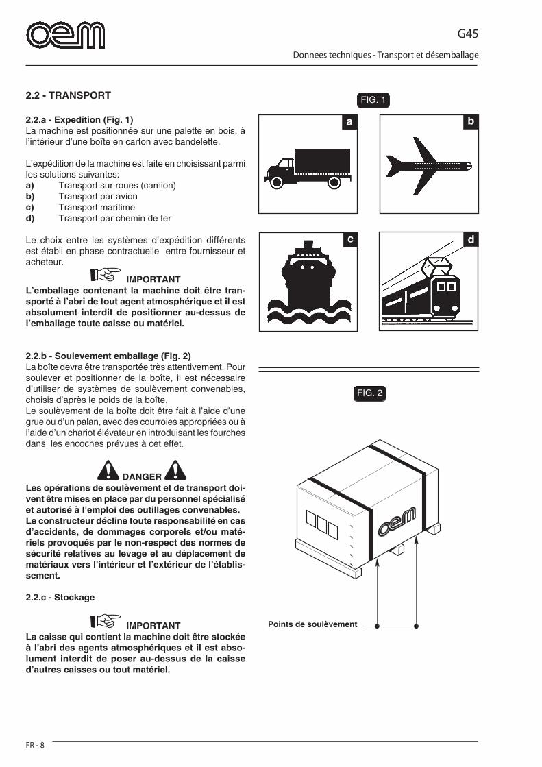
G45
FR - 8
Donnees techniques - Transport et désemballage
a b
c d
FIG. 2
FIG. 1FIG. 1
FIG. 2
2.2 - TRANSPORT
2.2.a - Expedition (Fig. 1)La machine est positionnée sur une palette en bois, à l’intérieur d’une boîte en carton avec bandelette.
L’expédition de la machine est faite en choisissant parmi les solutions suivantes:a) Transport sur roues (camion)b) Transport par avionc) Transport maritimed) Transport par chemin de fer
Le choix entre les systèmes d’expédition différents est établi en phase contractuelle entre fournisseur et acheteur.
IMPORTANTL’emballage contenant la machine doit être tran-sporté à l’abri de tout agent atmosphérique et il est absolument interdit de positionner au-dessus de l’emballage toute caisse ou matériel.
2.2.b - Soulevement emballage (Fig. 2)La boîte devra être transportée très attentivement. Pour soulever et positionner de la boîte, il est nécessaire d’utiliser de systèmes de soulèvement convenables, choisis d’après le poids de la boîte.Le soulèvement de la boîte doit être fait à l’aide d’une grue ou d’un palan, avec des courroies appropriées ou à l’aide d’un chariot élévateur en introduisant les fourches dans les encoches prévues à cet effet.
DANGER Les opérations de soulèvement et de transport doi-vent être mises en place par du personnel spécialisé et autorisé à l’emploi des outillages convenables.Le constructeur décline toute responsabilité en cas d’accidents, de dommages corporels et/ou maté-riels provoqués par le non-respect des normes de sécurité relatives au levage et au déplacement de matériaux vers l’intérieur et l’extérieur de l’établis-sement.
2.2.c - Stockage
IMPORTANTLa caisse qui contient la machine doit être stockée à l’abri des agents atmosphériques et il est abso-lument interdit de poser au-dessus de la caisse d’autres caisses ou tout matériel.
Points de soulèvement
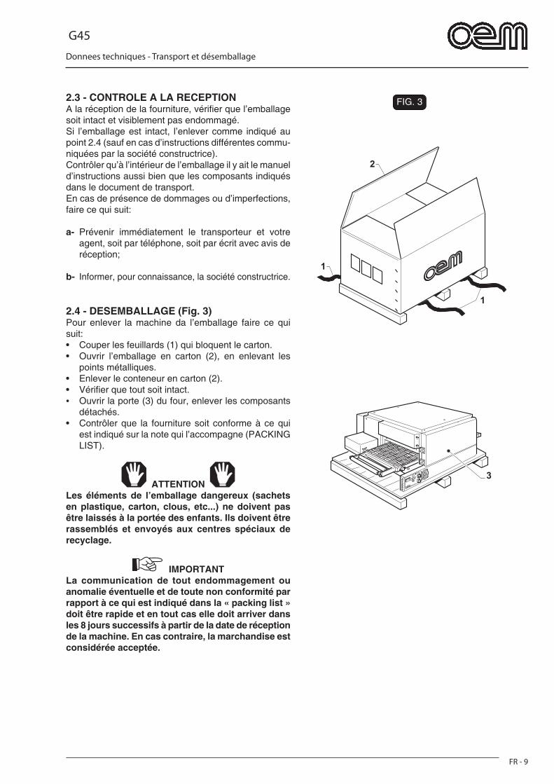
G45
FR - 9
Donnees techniques - Transport et désemballage
FIG. 3
1
1
2
3
2.3 - CONTROLE A LA RECEPTIONA la réception de la fourniture, vérifi er que l’emballage soit intact et visiblement pas endommagé.Si l’emballage est intact, l’enlever comme indiqué au point 2.4 (sauf en cas d’instructions différentes commu-niquées par la société constructrice).Contrôler qu’à l’intérieur de l’emballage il y ait le manuel d’instructions aussi bien que les composants indiqués dans le document de transport. En cas de présence de dommages ou d’imperfections, faire ce qui suit:
a- Prévenir immédiatement le transporteur et votre agent, soit par téléphone, soit par écrit avec avis de réception;
b- Informer, pour connaissance, la société constructrice.
2.4 - DESEMBALLAGE (Fig. 3)Pour enlever la machine da l’emballage faire ce qui suit:• Couper les feuillards (1) qui bloquent le carton.• Ouvrir l’emballage en carton (2), en enlevant les
points métalliques.• Enlever le conteneur en carton (2).• Vérifi er que tout soit intact.• Ouvrir la porte (3) du four, enlever les composants
détachés.• Contrôler que la fourniture soit conforme à ce qui
est indiqué sur la note qui l’accompagne (PACKING LIST).
ATTENTION Les éléments de l’emballage dangereux (sachets en plastique, carton, clous, etc...) ne doivent pas être laissés à la portée des enfants. Ils doivent être rassemblés et envoyés aux centres spéciaux de recyclage.
IMPORTANTLa communication de tout endommagement ou anomalie éventuelle et de toute non conformité par rapport à ce qui est indiqué dans la « packing list » doit être rapide et en tout cas elle doit arriver dans les 8 jours successifs à partir de la date de réception de la machine. En cas contraire, la marchandise est considérée acceptée.
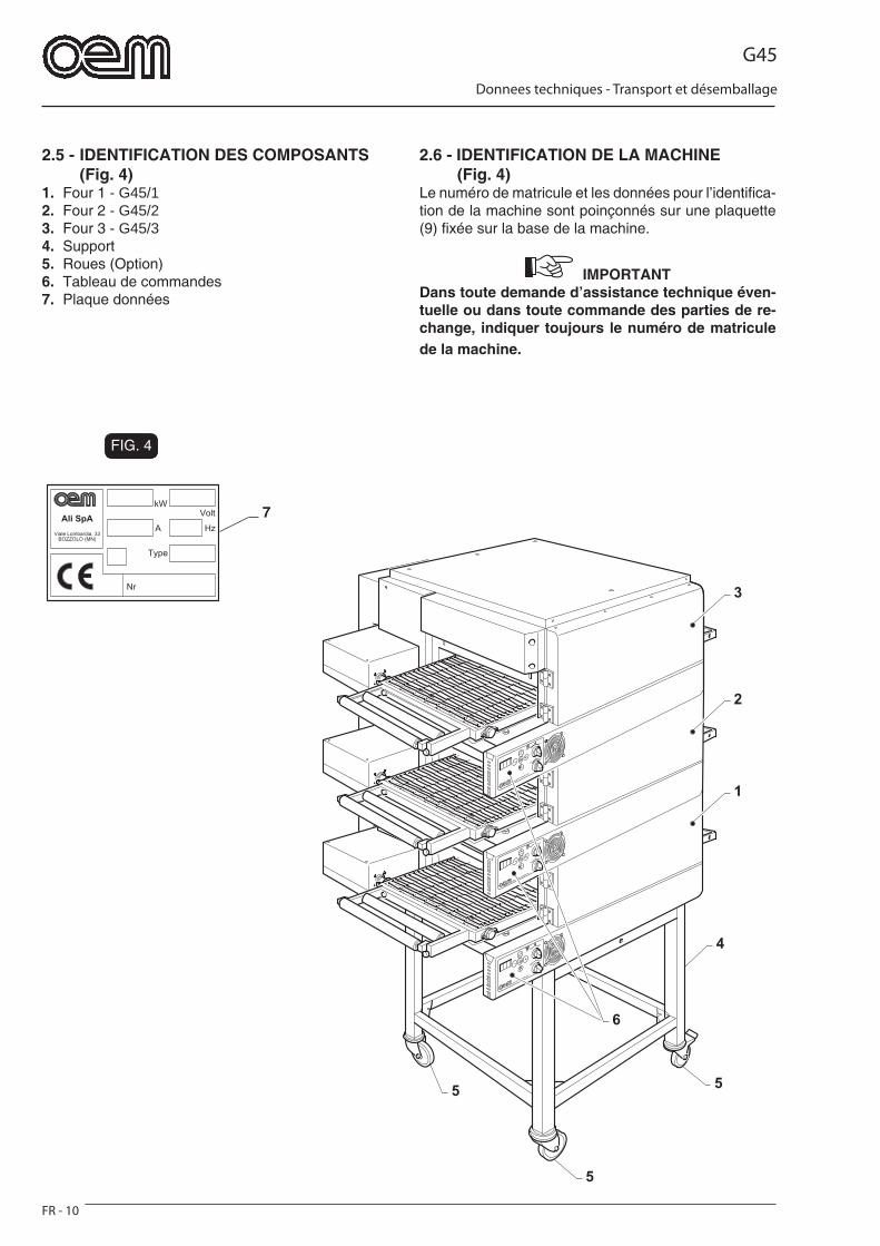
G45
FR - 10
Donnees techniques - Transport et désemballage
FIG. 4
7
5
55
4
6
1
2
3
2.5 - IDENTIFICATION DES COMPOSANTS (Fig. 4)1. Four 1 - G45/12. Four 2 - G45/23. Four 3 - G45/34. Support5. Roues (Option)6. Tableau de commandes7. Plaque données
2.6 - IDENTIFICATION DE LA MACHINE (Fig. 4)
Le numéro de matricule et les données pour l’identifi ca-tion de la machine sont poinçonnés sur une plaquette (9) fi xée sur la base de la machine.
IMPORTANT Dans toute demande d’assistance technique éven-tuelle ou dans toute commande des parties de re-change, indiquer toujours le numéro de matricule de la machine.
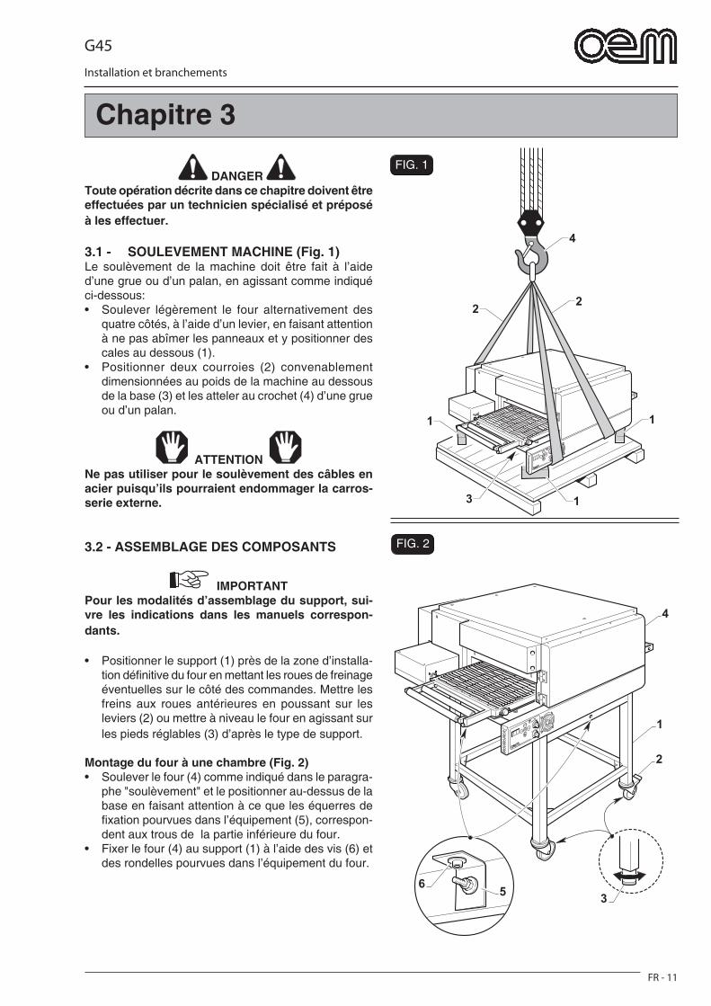
G45
FR - 11
Installation et branchements
FIG. 2
FIG. 1
4
22
1 1
13
1
3
2
4
65
DANGER Toute opération décrite dans ce chapitre doivent être effectuées par un technicien spécialisé et préposé à les effectuer.
3.1 - SOULEVEMENT MACHINE (Fig. 1)Le soulèvement de la machine doit être fait à l’aide d’une grue ou d’un palan, en agissant comme indiqué ci-dessous:• Soulever légèrement le four alternativement des
quatre côtés, à l’aide d’un levier, en faisant attention à ne pas abîmer les panneaux et y positionner des cales au dessous (1).
• Positionner deux courroies (2) convenablement dimensionnées au poids de la machine au dessous de la base (3) et les atteler au crochet (4) d’une grue ou d’un palan.
ATTENTION Ne pas utiliser pour le soulèvement des câbles en acier puisqu’ils pourraient endommager la carros-serie externe.
3.2 - ASSEMBLAGE DES COMPOSANTS
IMPORTANTPour les modalités d’assemblage du support, sui-vre les indications dans les manuels correspon-dants.
• Positionner le support (1) près de la zone d’installa-tion défi nitive du four en mettant les roues de freinage éventuelles sur le côté des commandes. Mettre les freins aux roues antérieures en poussant sur les leviers (2) ou mettre à niveau le four en agissant sur les pieds réglables (3) d’après le type de support.
Montage du four à une chambre (Fig. 2)• Soulever le four (4) comme indiqué dans le paragra-
phe "soulèvement" et le positionner au-dessus de la base en faisant attention à ce que les équerres de fi xation pourvues dans l’équipement (5), correspon-dent aux trous de la partie inférieure du four.
• Fixer le four (4) au support (1) à l’aide des vis (6) et des rondelles pourvues dans l’équipement du four.
Chapitre 3

G45
FR - 12
Installation et branchements
FIG. 3
FIG. 41
2
T
F3 N
3
F2F1
1
2
3
4
Montage des fours à deux ou à trois chambres (Fig.3)(Seulement pour les modèles G45/2-G45/3)• Pour le montage du four à deux ou à trois chambres,
mettre le deuxième four (2) au-dessus du premier (1) et le fi xer à l’aide des brides (3) et des vis (4).
• Pour fours à trois chambres positionner le troisième four au dessus du deuxième et le fi xer comme indi-qué au point précédent.
3.3 - BRANCHEMENT ELECTRIQUE (Fig. 8)
DANGER • La ligne électrique d’alimentation doit être
pourvue d’un SECTIONNEUR de LIGNE omnipo-laire convenable (interrupteur automatique thermo-magnétique ou différentiel) positionné avant l’in-terrupteur général de l’unité de commande avec ouverture des contactes de 3 mm minimum.
• Le système de mise à la terre doit être conforme aux normes électriques nationales en vigueur dans le lieu d’installation.
• Les câbles électriques d’alimentation doivent être dimensionnés selon le courant maximum demandé par la machine; cela faisant, la chute de tension totale, à plein charge, devra être in-férieure à 2%.
• Les données concernant la ligne électrique d’ali-mentation doivent correspondre aux indications sur la plaquette d’identifi cation et aux donnés indiqués dans le tableau des caractéristiques techniques dans l’introduction de ce manuel.
DANGER Avant d’effectuer le branchement électrique, s’assurer que le SECTIONNEUR de LIGNE soit débranché (ligne pas en tension).
3.3.a - Branchement électrique du four• Enlever le panneau postérieur (1) pour accéder à la
partie électrique du four.• Brancher un câble électrique (2) opportunément di-
mensionné selon l’absorption du four à la borne (3) en connectant les trois phases aux bornes F1-F2-F3, le neutre à la borne N et la terre à la borne T.
• Insérer le câble électrique (2) dans l’élément de pas-sage préposé et le brancher au sectionneur de ligne positionné en amont du four.
IMPORTANTLe sectionneur de ligne positionné en amont du four doit être dans une zone facilement accessible.
• Monter à nouveau le panneau postérieur (1).
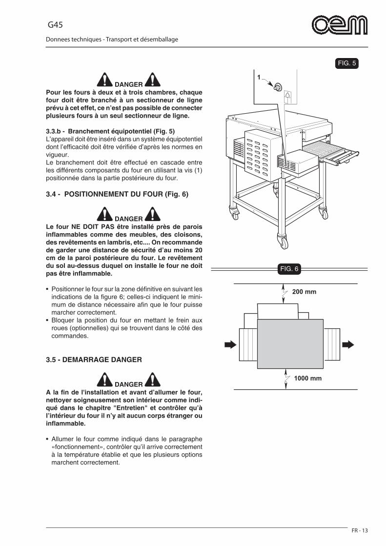
G45
FR - 13
Donnees techniques - Transport et désemballage
FIG. 5
1
FIG. 6
200 mm
1000 mm
DANGER Pour les fours à deux et à trois chambres, chaque four doit être branché à un sectionneur de ligne prévu à cet effet, ce n’est pas possible de connecter plusieurs fours à un seul sectionneur de ligne.
3.3.b - Branchement équipotentiel (Fig. 5)L’appareil doit être inséré dans un système équipotentiel dont l’effi cacité doit être vérifi ée d’après les normes en vigueur.Le branchement doit être effectué en cascade entre les différents composants du four en utilisant la vis (1) positionnée dans la partie postérieure du four.
3.4 - POSITIONNEMENT DU FOUR (Fig. 6)
DANGER Le four NE DOIT PAS être installé près de parois infl ammables comme des meubles, des cloisons, des revêtements en lambris, etc.... On recommande de garder une distance de sécurité d’au moins 20 cm de la paroi postérieure du four. Le revêtement du sol au-dessus duquel on installe le four ne doit pas être infl ammable.
• Positionner le four sur la zone défi nitive en suivant les indications de la fi gure 6; celles-ci indiquent le mini-mum de distance nécessaire afi n que le four puisse marcher correctement.
• Bloquer la position du four en mettant le frein aux roues (optionnelles) qui se trouvent dans le côté des commandes.
3.5 - DEMARRAGE DANGER
DANGER A la fi n de l'installation et avant d’allumer le four, nettoyer soigneusement son intérieur comme indi-qué dans le chapitre "Entretien" et contrôler qu’à l’intérieur du four il n’y ait aucun corps étranger ou infl ammable.
• Allumer le four comme indiqué dans le paragraphe «fonctionnement», contrôler qu’il arrive correctement à la température établie et que les plusieurs options marchent correctement.
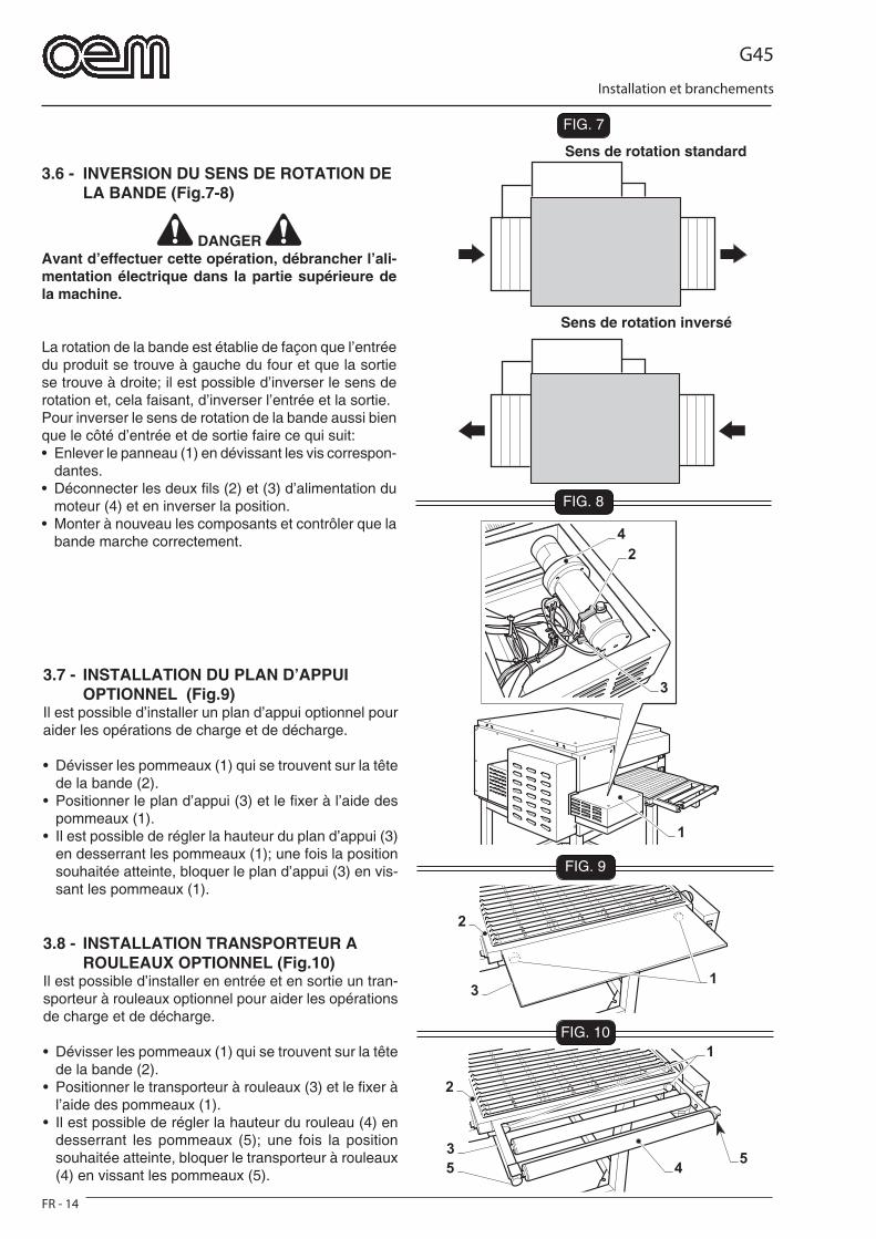
G45
FR - 14
Installation et branchements
FIG. 7
FIG. 8
FIG. 9
4
2
3
1
45
3
2
1
5
2
13
FIG. 10
3.6 - INVERSION DU SENS DE ROTATION DE LA BANDE (Fig.7-8)
DANGER Avant d’effectuer cette opération, débrancher l’ali-mentation électrique dans la partie supérieure de la machine.
La rotation de la bande est établie de façon que l’entrée du produit se trouve à gauche du four et que la sortie se trouve à droite; il est possible d’inverser le sens de rotation et, cela faisant, d’inverser l’entrée et la sortie.Pour inverser le sens de rotation de la bande aussi bien que le côté d’entrée et de sortie faire ce qui suit:• Enlever le panneau (1) en dévissant les vis correspon-
dantes.• Déconnecter les deux fi ls (2) et (3) d’alimentation du
moteur (4) et en inverser la position.• Monter à nouveau les composants et contrôler que la
bande marche correctement.
Sens de rotation standard
Sens de rotation inversé
3.7 - INSTALLATION DU PLAN D’APPUI OPTIONNEL (Fig.9)Il est possible d’installer un plan d’appui optionnel pour aider les opérations de charge et de décharge.
• Dévisser les pommeaux (1) qui se trouvent sur la tête de la bande (2).
• Positionner le plan d’appui (3) et le fi xer à l’aide des pommeaux (1).
• Il est possible de régler la hauteur du plan d’appui (3) en desserrant les pommeaux (1); une fois la position souhaitée atteinte, bloquer le plan d’appui (3) en vis-sant les pommeaux (1).
3.8 - INSTALLATION TRANSPORTEUR A ROULEAUX OPTIONNEL (Fig.10)Il est possible d’installer en entrée et en sortie un tran-sporteur à rouleaux optionnel pour aider les opérations de charge et de décharge.
• Dévisser les pommeaux (1) qui se trouvent sur la tête de la bande (2).
• Positionner le transporteur à rouleaux (3) et le fi xer à l’aide des pommeaux (1).
• Il est possible de régler la hauteur du rouleau (4) en desserrant les pommeaux (5); une fois la position souhaitée atteinte, bloquer le transporteur à rouleaux (4) en vissant les pommeaux (5).
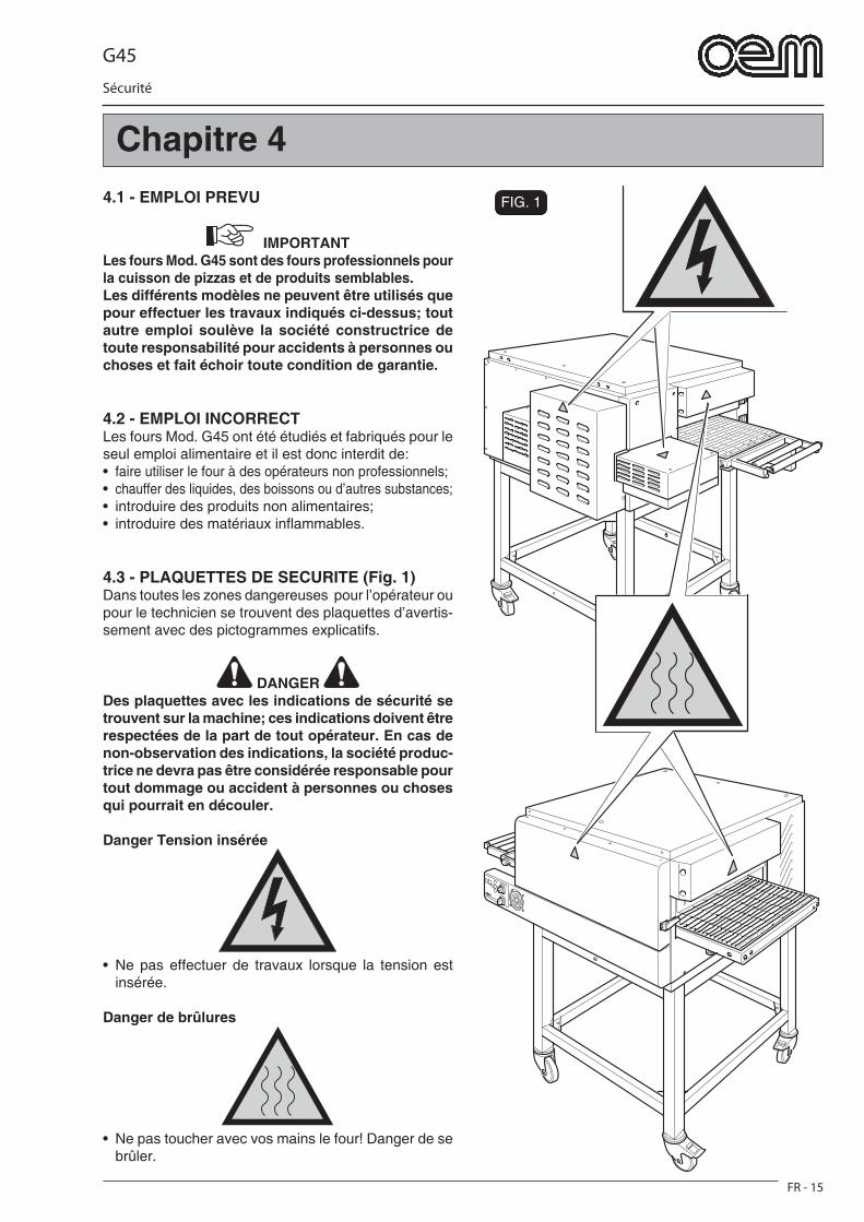
G45
Sécurité
FR - 15
FIG. 14.1 - EMPLOI PREVU
IMPORTANT Les fours Mod. G45 sont des fours professionnels pour la cuisson de pizzas et de produits semblables.Les différents modèles ne peuvent être utilisés que pour effectuer les travaux indiqués ci-dessus; tout autre emploi soulève la société constructrice de toute responsabilité pour accidents à personnes ou choses et fait échoir toute condition de garantie.
4.2 - EMPLOI INCORRECTLes fours Mod. G45 ont été étudiés et fabriqués pour le seul emploi alimentaire et il est donc interdit de:• faire utiliser le four à des opérateurs non professionnels;• chauffer des liquides, des boissons ou d’autres substances;• introduire des produits non alimentaires;• introduire des matériaux infl ammables.
4.3 - PLAQUETTES DE SECURITE (Fig. 1)Dans toutes les zones dangereuses pour l’opérateur ou pour le technicien se trouvent des plaquettes d’avertis-sement avec des pictogrammes explicatifs.
DANGER Des plaquettes avec les indications de sécurité se trouvent sur la machine; ces indications doivent être respectées de la part de tout opérateur. En cas de non-observation des indications, la société produc-trice ne devra pas être considérée responsable pour tout dommage ou accident à personnes ou choses qui pourrait en découler.
Danger Tension insérée
• Ne pas effectuer de travaux lorsque la tension est insérée.
Danger de brûlures
• Ne pas toucher avec vos mains le four! Danger de se brûler.
Chapitre 4
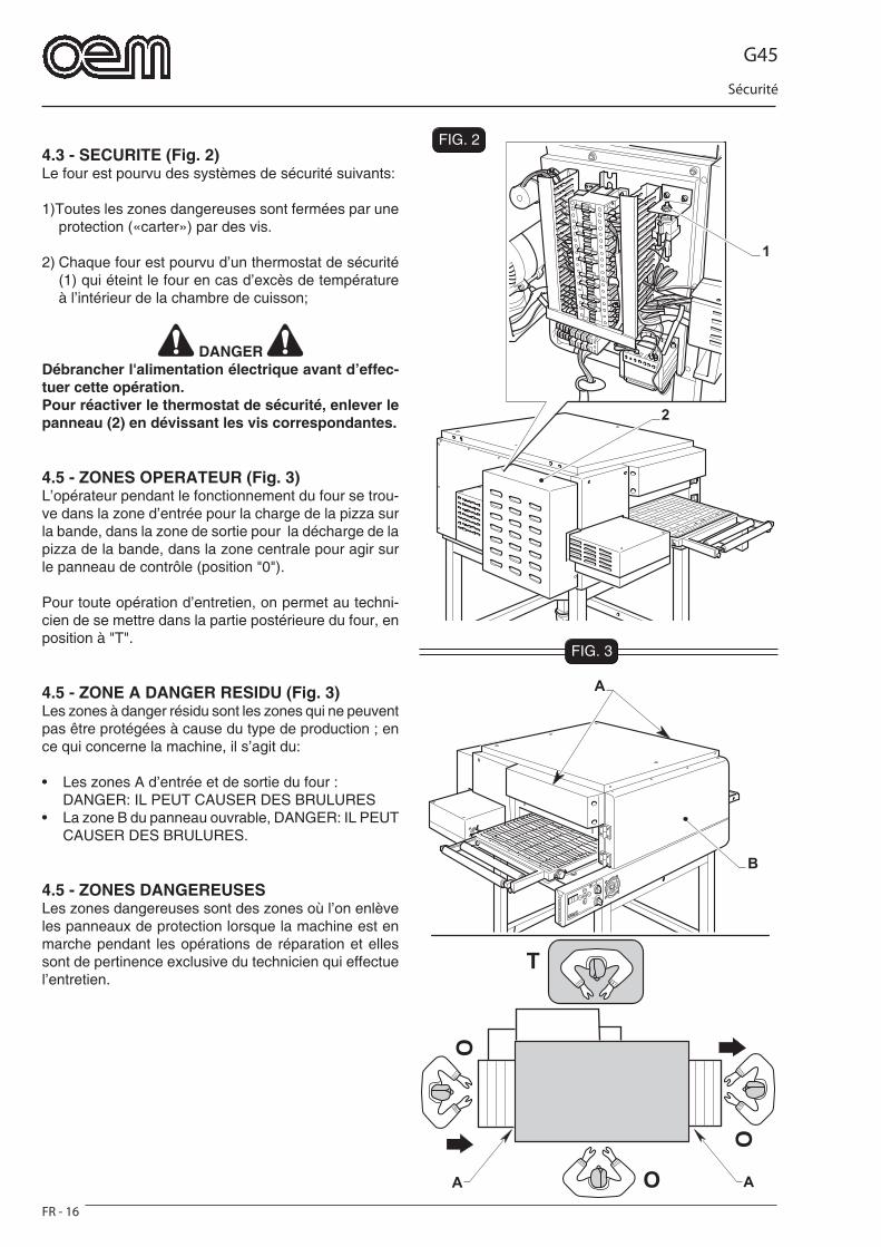
G45
Sécurité
FR - 16
FIG. 3
O
O
O
T
AA
B
A
2
1
FIG. 24.3 - SECURITE (Fig. 2)Le four est pourvu des systèmes de sécurité suivants:
1)Toutes les zones dangereuses sont fermées par une protection («carter») par des vis.
2) Chaque four est pourvu d’un thermostat de sécurité (1) qui éteint le four en cas d’excès de température à l’intérieur de la chambre de cuisson;
DANGER Débrancher l'alimentation électrique avant d’effec-tuer cette opération.Pour réactiver le thermostat de sécurité, enlever le panneau (2) en dévissant les vis correspondantes.
4.5 - ZONES OPERATEUR (Fig. 3)L’opérateur pendant le fonctionnement du four se trou-ve dans la zone d’entrée pour la charge de la pizza sur la bande, dans la zone de sortie pour la décharge de la pizza de la bande, dans la zone centrale pour agir sur le panneau de contrôle (position "0").
Pour toute opération d’entretien, on permet au techni-cien de se mettre dans la partie postérieure du four, en position à "T".
4.5 - ZONE A DANGER RESIDU (Fig. 3)Les zones à danger résidu sont les zones qui ne peuvent pas être protégées à cause du type de production ; en ce qui concerne la machine, il s’agit du:
• Les zones A d’entrée et de sortie du four : DANGER: IL PEUT CAUSER DES BRULURES• La zone B du panneau ouvrable, DANGER: IL PEUT
CAUSER DES BRULURES.
4.5 - ZONES DANGEREUSESLes zones dangereuses sont des zones où l’on enlève les panneaux de protection lorsque la machine est en marche pendant les opérations de réparation et elles sont de pertinence exclusive du technicien qui effectue l’entretien.
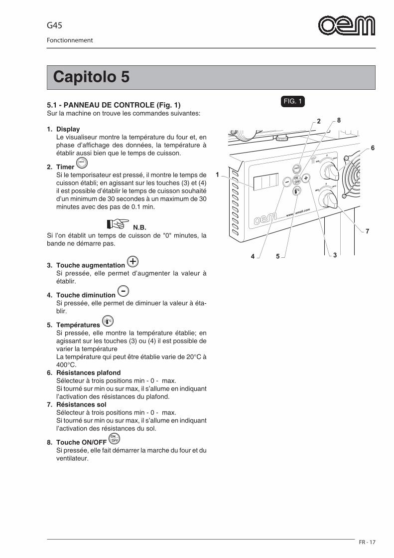
G45
FR - 17
Fonctionnement
Capitolo 5FIG. 1
2
6
7
54 3
8
1
5.1 - PANNEAU DE CONTROLE (Fig. 1)Sur la machine on trouve les commandes suivantes:
1. Display Le visualiseur montre la température du four et, en
phase d’affi chage des données, la température à établir aussi bien que le temps de cuisson.
2. Timer Si le temporisateur est pressé, il montre le temps de
cuisson établi; en agissant sur les touches (3) et (4) il est possible d’établir le temps de cuisson souhaité d’un minimum de 30 secondes à un maximum de 30 minutes avec des pas de 0.1 min.
N.B. Si l’on établit un temps de cuisson de "0" minutes, la bande ne démarre pas.
3. Touche augmentation Si pressée, elle permet d’augmenter la valeur à
établir.
4. Touche diminution Si pressée, elle permet de diminuer la valeur à éta-
blir.
5. Températures Si pressée, elle montre la température établie; en
agissant sur les touches (3) ou (4) il est possible de varier la température
La température qui peut être établie varie de 20°C à 400°C.
6. Résistances plafond Sélecteur à trois positions min - 0 - max. Si tourné sur min ou sur max, il s’allume en indiquant
l’activation des résistances du plafond.7. Résistances sol Sélecteur à trois positions min - 0 - max. Si tourné sur min ou sur max, il s’allume en indiquant
l’activation des résistances du sol.
8. Touche ON/OFF Si pressée, elle fait démarrer la marche du four et du
ventilateur.
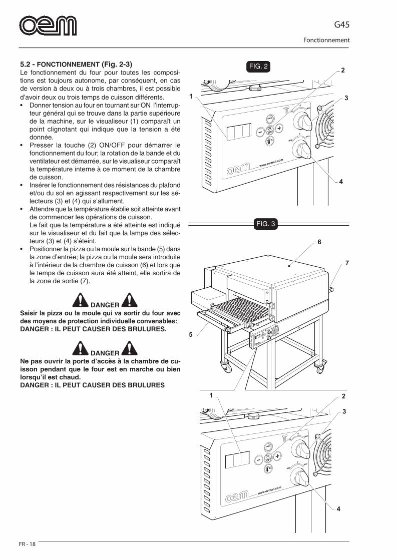
G45
FR - 18
Fonctionnement
FIG. 2
3
4
21
7
6
5
FIG. 3
3
4
2
1
5.2 - FONCTIONNEMENT (Fig. 2-3)Le fonctionnement du four pour toutes les composi-tions est toujours autonome, par conséquent, en cas de version à deux ou à trois chambres, il est possible d’avoir deux ou trois temps de cuisson différents.• Donner tension au four en tournant sur ON l’interrup-
teur général qui se trouve dans la partie supérieure de la machine, sur le visualiseur (1) comparaît un point clignotant qui indique que la tension a été donnée.
• Presser la touche (2) ON/OFF pour démarrer le fonctionnement du four; la rotation de la bande et du ventilateur est démarrée, sur le visualiseur comparaît la température interne à ce moment de la chambre de cuisson.
• Insérer le fonctionnement des résistances du plafond et/ou du sol en agissant respectivement sur les sé-lecteurs (3) et (4) qui s’allument.
• Attendre que la température établie soit atteinte avant de commencer les opérations de cuisson.
Le fait que la température a été atteinte est indiqué sur le visualiseur et du fait que la lampe des sélec-teurs (3) et (4) s’éteint.
• Positionner la pizza ou la moule sur la bande (5) dans la zone d’entrée; la pizza ou la moule sera introduite à l’intérieur de la chambre de cuisson (6) et lors que le temps de cuisson aura été atteint, elle sortira de la zone de sortie (7).
DANGER Saisir la pizza ou la moule qui va sortir du four avec des moyens de protection individuelle convenables: DANGER : IL PEUT CAUSER DES BRULURES.
DANGER Ne pas ouvrir la porte d’accès à la chambre de cu-isson pendant que le four est en marche ou bien lorsqu’il est chaud.DANGER : IL PEUT CAUSER DES BRULURES
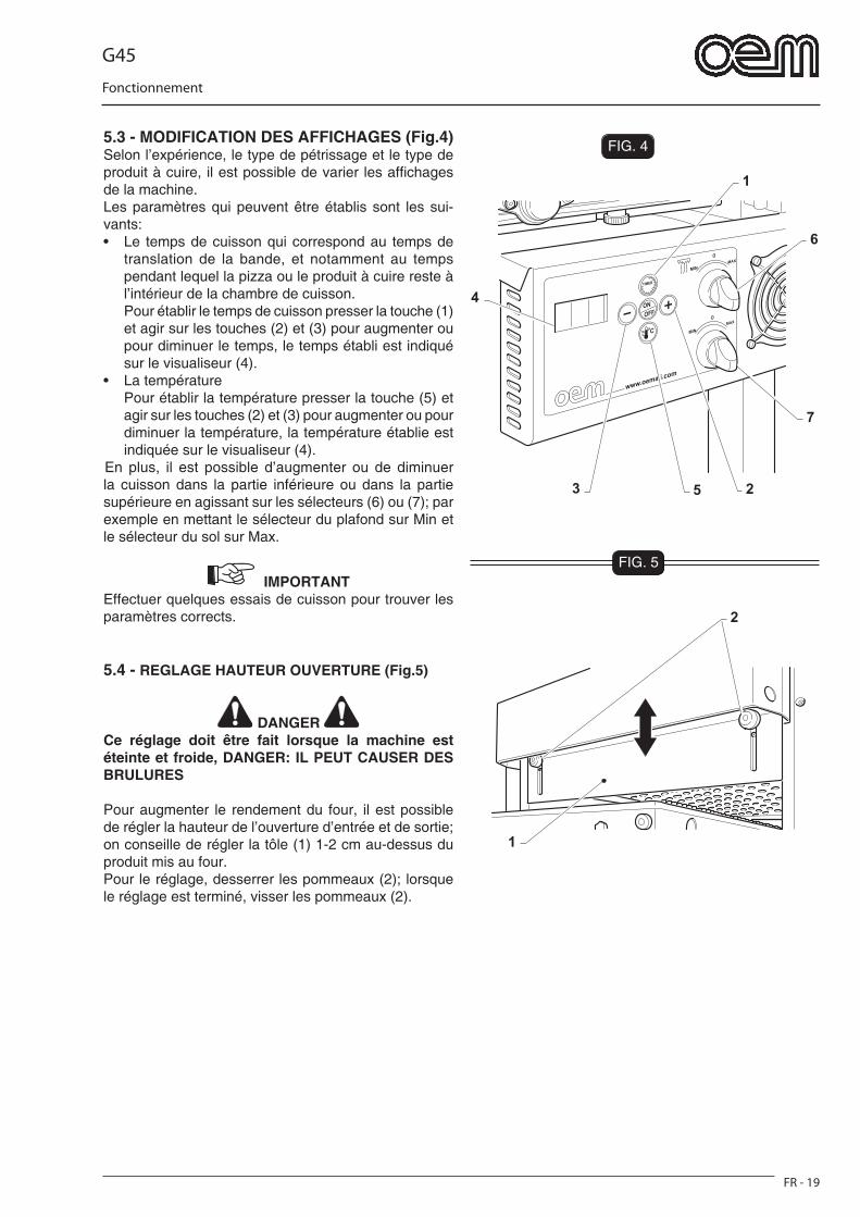
G45
FR - 19
Fonctionnement
FIG. 4
1
6
7
53 2
4
1
2
FIG. 5
5.3 - MODIFICATION DES AFFICHAGES (Fig.4)Selon l’expérience, le type de pétrissage et le type de produit à cuire, il est possible de varier les affi chages de la machine.Les paramètres qui peuvent être établis sont les sui-vants:• Le temps de cuisson qui correspond au temps de
translation de la bande, et notamment au temps pendant lequel la pizza ou le produit à cuire reste à l’intérieur de la chambre de cuisson.
Pour établir le temps de cuisson presser la touche (1) et agir sur les touches (2) et (3) pour augmenter ou pour diminuer le temps, le temps établi est indiqué sur le visualiseur (4).
• La température Pour établir la température presser la touche (5) et
agir sur les touches (2) et (3) pour augmenter ou pour diminuer la température, la température établie est indiquée sur le visualiseur (4).
En plus, il est possible d’augmenter ou de diminuer la cuisson dans la partie inférieure ou dans la partie supérieure en agissant sur les sélecteurs (6) ou (7); par exemple en mettant le sélecteur du plafond sur Min et le sélecteur du sol sur Max.
IMPORTANT Effectuer quelques essais de cuisson pour trouver les paramètres corrects.
5.4 - REGLAGE HAUTEUR OUVERTURE (Fig.5)
DANGER Ce réglage doit être fait lorsque la machine est éteinte et froide, DANGER: IL PEUT CAUSER DES BRULURES
Pour augmenter le rendement du four, il est possible de régler la hauteur de l’ouverture d’entrée et de sortie; on conseille de régler la tôle (1) 1-2 cm au-dessus du produit mis au four.Pour le réglage, desserrer les pommeaux (2); lorsque le réglage est terminé, visser les pommeaux (2).

G45
FR - 20
Fonctionnement
5.5 - ALARMES PENDANT LE FONCTIONNEMENTDes alarmes peuvent comparaître pendant le fonction-nement. Ils sont déclanchés par des ruptures ou par une température excessive; ces alarmes sont indi-quées sur le visualiseur. 5.5.a - Alarme sonde température endommagée ou débranchée Quand ces alarmes sont insérées, ce qui suit compa-raît sur le visualiseur:
o • Automatiquement l'alimentation aux résistances est
interrompue.• Eteindre le four et s’adresser au service d’assistance
technique.
5.5.b - Alarme moteur bandeQuand cette alarme est déclenchée, cela signifi e que le moteur de la bande est en train de faire face à des problèmes; la bande est arrêtée et ce qui suit compa-raît sur le visualiseur:
AL3
• Eteindre le four et s’adresser su service d’assistance technique.
5.5.c - Alarme température du four excessiveCette alarme est déclenchée lorsque la température du four dépasse les 430°;Ce qui suit comparaît sur le visualiseur:
AL4
• Automatiquement l'alimentation aux résistances est interrompue.
• Eteindre le four et s’adresser au service d’assistance technique.
5.6 - ARRET (Fig.6)• A la fi n de la journée de travail éteindre le four en
pressant la touche (1) .• La rotation de la bande s’arrête et les résistances
s’éteignent, mais le ventilateur continue à marcher jusqu’à ce que la température à l’intérieur du four atteint les 60°C.
• Quand le four est allumé à nouveau, il s’allume avec les données établies lors de son arrêt.
IMPORTANT Ne pas déconnecter l’interrupteur qui se trouve dans la partie supérieure de la machine jusqu’au moment où le ventilateur s’éteint.

G45
FR - 21
Fonctionnement
FIG. 6
1
5.7 - MAUVAIS FONCTIONNEMENT, CAUSES ET REMEDES (Fig.7)
- Le four ne s’allume pas:
• Contrôler que le branchement électrique soit cor-rect.
• Contrôler que l’interrupteur général soit inséré• Appeler le service d’assistance technique.
- Le produit cuisiné ne résulte pas cuit de façon uniforme:
• Régler le temps de cuisson• Régler la température du four
- Mauvais fonctionnement du four:
• La température établie n’est pas atteinte: Résistances en panne Contrôler le branchement électrique du four Appeler le service d’assistance technique.
DANGER Pour tout autre problème, s’adresser au Service d’assistance technique.
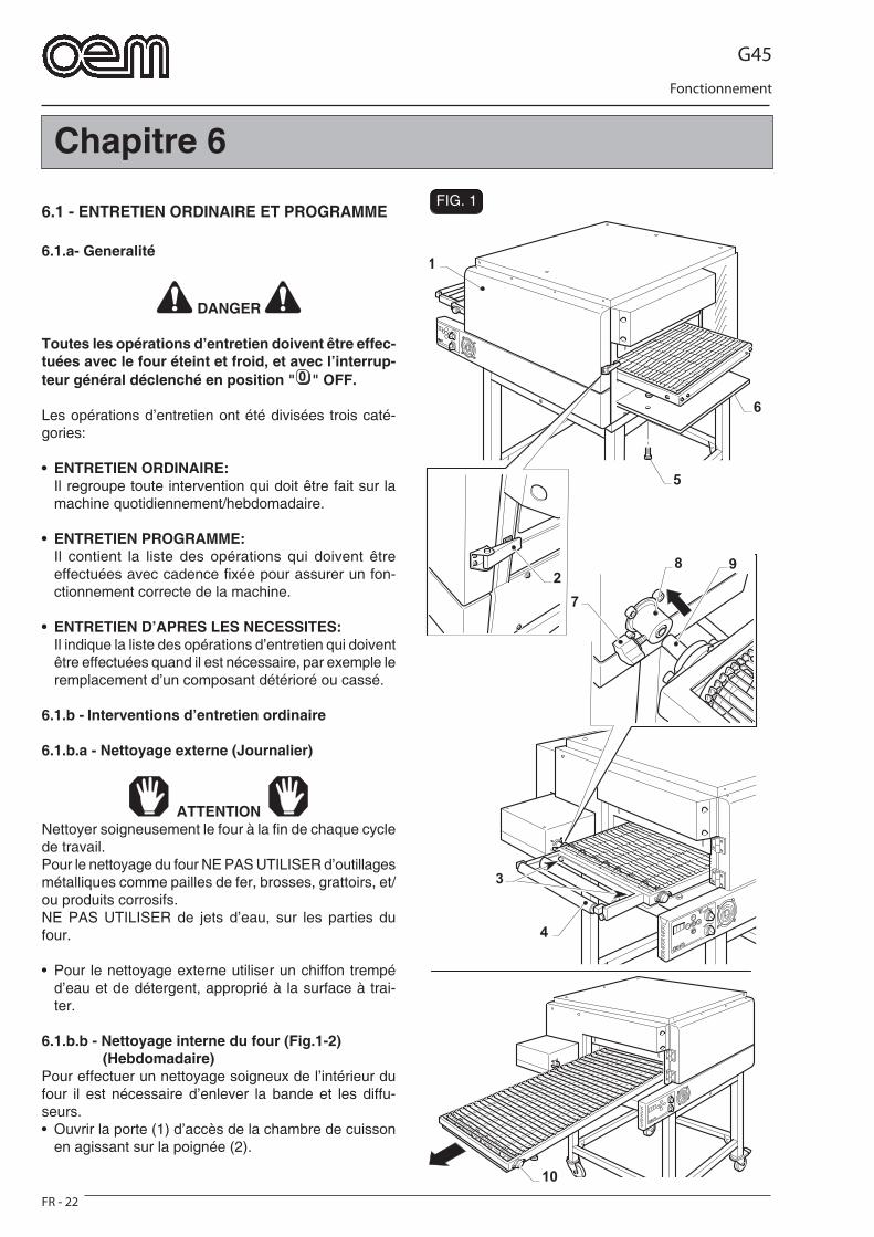
G45
FR - 22
Fonctionnement
1
6
3
4
8 9
7
10
2
5
FIG. 1
Chapitre 6
6.1 - ENTRETIEN ORDINAIRE ET PROGRAMME
6.1.a- Generalité
DANGER
Toutes les opérations d’entretien doivent être effec-tuées avec le four éteint et froid, et avec l’interrup-teur général déclenché en position " " OFF.
Les opérations d’entretien ont été divisées trois caté-gories:
• ENTRETIEN ORDINAIRE: Il regroupe toute intervention qui doit être fait sur la
machine quotidiennement/hebdomadaire.
• ENTRETIEN PROGRAMME: Il contient la liste des opérations qui doivent être
effectuées avec cadence fi xée pour assurer un fon-ctionnement correcte de la machine.
• ENTRETIEN D’APRES LES NECESSITES: Il indique la liste des opérations d’entretien qui doivent
être effectuées quand il est nécessaire, par exemple le remplacement d’un composant détérioré ou cassé.
6.1.b - Interventions d’entretien ordinaire
6.1.b.a - Nettoyage externe (Journalier)
ATTENTION Nettoyer soigneusement le four à la fi n de chaque cycle de travail.Pour le nettoyage du four NE PAS UTILISER d’outillages métalliques comme pailles de fer, brosses, grattoirs, et/ou produits corrosifs.NE PAS UTILISER de jets d’eau, sur les parties du four.
• Pour le nettoyage externe utiliser un chiffon trempé d’eau et de détergent, approprié à la surface à trai-ter.
6.1.b.b - Nettoyage interne du four (Fig.1-2) (Hebdomadaire)Pour effectuer un nettoyage soigneux de l’intérieur du four il est nécessaire d’enlever la bande et les diffu-seurs.• Ouvrir la porte (1) d’accès de la chambre de cuisson
en agissant sur la poignée (2).
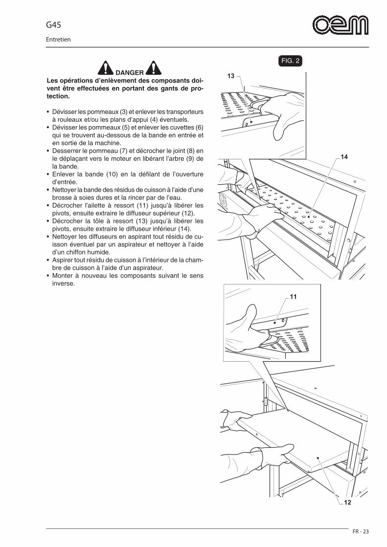
G45
FR - 23
Entretien
FIG. 2
12
11
14
13 DANGER
Les opérations d’enlèvement des composants doi-vent être effectuées en portant des gants de pro-tection.
• Dévisser les pommeaux (3) et enlever les transporteurs à rouleaux et/ou les plans d’appui (4) éventuels.
• Dévisser les pommeaux (5) et enlever les cuvettes (6) qui se trouvent au-dessous de la bande en entrée et en sortie de la machine.
• Desserrer le pommeau (7) et décrocher le joint (8) en le déplaçant vers le moteur en libérant l’arbre (9) de la bande.
• Enlever la bande (10) en la défi lant de l’ouverture d’entrée.
• Nettoyer la bande des résidus de cuisson à l’aide d’une brosse à soies dures et la rincer par de l’eau.
• Décrocher l'ailette à ressort (11) jusqu’à libérer les pivots, ensuite extraire le diffuseur supérieur (12).
• Décrocher la tôle à ressort (13) jusqu’à libérer les pivots, ensuite extraire le diffuseur inférieur (14).
• Nettoyer les diffuseurs en aspirant tout résidu de cu-isson éventuel par un aspirateur et nettoyer à l’aide d’un chiffon humide.
• Aspirer tout résidu de cuisson à l’intérieur de la cham-bre de cuisson à l’aide d’un aspirateur.
• Monter à nouveau les composants suivant le sens inverse.
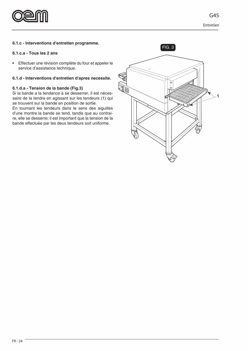
G45
FR - 24
Entretien
FIG. 3
1
6.1.c - Interventions d'entretien programme.
6.1.c.a - Tous les 2 ans
• Effectuer une révision complète du four et appeler le service d’assistance technique.
6.1.d - Interventions d'entretien d'apres necessite.
6.1.d.a - Tension de la bande (Fig.3)Si la bande a la tendance à se desserrer, il est néces-saire de la tendre en agissant sur les tendeurs (1) qui se trouvent sur la bande en position de sortie.En tournant les tendeurs dans le sens des aiguilles d’une montre la bande se tend, tandis que au contrai-re, elle se desserre; il est important que la tension de la bande effectuée par les deux tendeurs soit uniforme.

G45
FR - 25
Demontage - Demantelement - Elimination
Chapitre 7
7.1 - DEMONTAGE DE LA MACHINES’il est nécessaire de démonter la machine pour procé-der successivement à une nouvelle installation, il faut procéder dans le sens inverse à ce qui est indiqué au chapitre «Installation».
DANGER Avant de procéder au démontage de l’installation déconnecter l’alimentation électrique.
Cette opération doit être effectuée par un technicien spécialisé, qualifi é et préposé à de telles interven-tions.
ATTENTION S’il est nécessaire de démonter la machine, ou quelqu’un de ses composants, de façon différente par rapport à ce qu’il est décrit, consulter la société constructeur, ou bien son Agent, en s’adressant aux coordonnées indiquées dans la troisième page de cette publication.
7.2 - DEMANTELEMENT DE LA MACHINE
Pour la sauvegarde de l’environne-ment, procéder selon la normative locale en vigueur.Lorsque l’appareil n’est plus utilisé ni réparable, procéder tri différencié des composants.
L’appareillage électrique ne peut pas être jeté com-me un déchet urbain. En effet, il faut respecter le ramassage séparé introduit par la discipline visant à l’élimination des ordures dérivant d’appareillages électriques.Les appareillages électriques sont caractérisés par un symbole portant une benne à ordures sur roues barrée. Le symbole indique que l’appareillage a été mis sur le marché après le 13 août 2005 et qu’il doit faire l’objet de ramassage séparé.L’écoulement inadéquat ou abusif des appareillages ou encore une utilisation impropre de ces derniers, si l’on considère les substances et matériaux con-tenus dans ces appareillages, peut provoquer des dommages aux personnes ou à l’environnement. L’écoulement des déchets électriques qui ne respec-tent pas les normes en vigueur comporte l’application de sanctions administratives et pénales.
ATTENTION En ce qui concerne la mise à la décharge des sub-stances nocives (lubrifi ants, solvants, vernis, etc.) veuillez consulter le paragraphe suivant.
7.3 - ELIMINATION DES SUBSTANCES NOCIVESPour procéder à l’élimination de ces substances se conformer aux prescriptions des normes en vigueur dans chaque pays.
ATTENTION Toute irrégularité commise par le Client avant, pen-dant ou après l’élimination ou le démantèlement des composants de la machine, dans l’interprétation et l’application des Normes en Vigueur en matière reste à sa complète responsabilité.
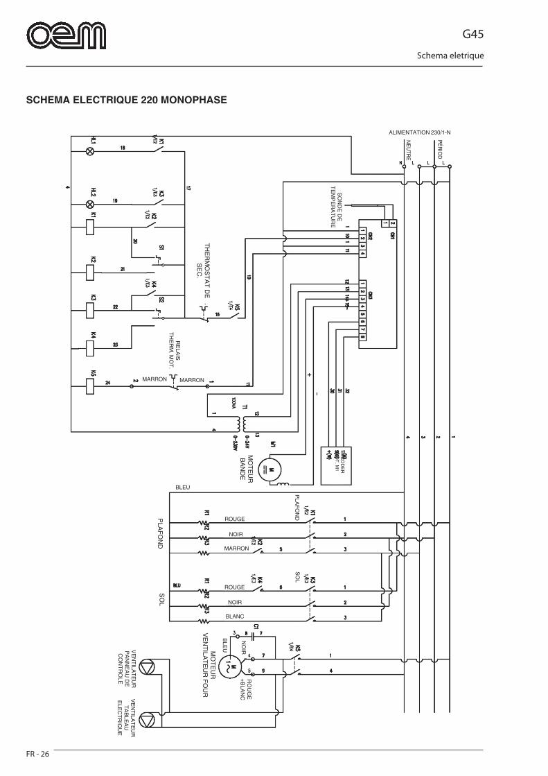
G45
FR - 26
Schema eletrique
SCHEMA ELECTRIQUE 220 MONOPHASE
ALIMENTATION 230/1-N
SO
ND
E D
E
TE
MP
ER
AT
UR
E
MARRON MARRON
RE
LAIS
T
HE
RM
. MO
T.
EN
CO
DE
R
MO
T. M
1
MO
TE
UR
B
AN
DE
TH
ER
MO
ST
AT
DE
S
EC
.
PLA
FO
ND
SO
L
ROUGE
NOIR
MARRON
ROUGE
NOIR
BLANC
BLEU
MO
TE
UR
V
EN
TILA
TE
UR
FO
UR
RO
UG
E+
BLA
NC
NO
IRVE
NT
ILAT
EU
R
PA
NN
EA
U D
E
CO
NT
RO
LE
BLE
U
VE
NT
ILAT
EU
R
TA
BLE
AU
E
LEC
TR
IQU
E
PLA
FO
ND
SO
L
PÉ
RIO
D
NE
UTR
E
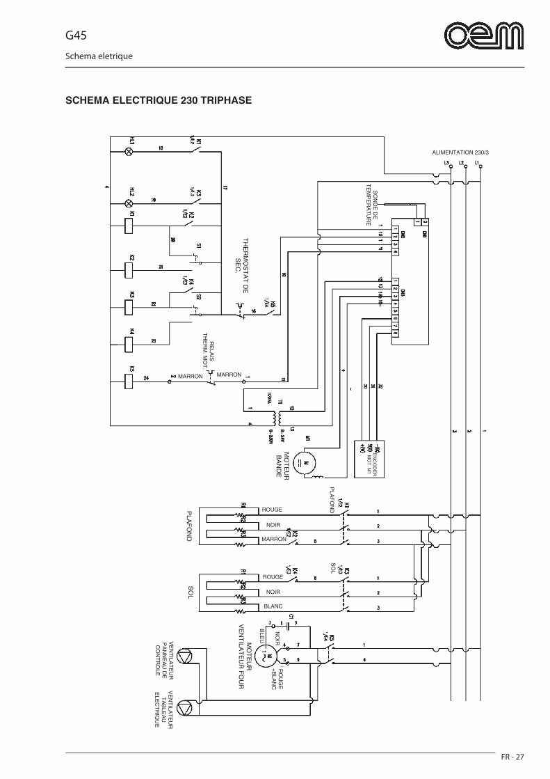
G45
FR - 27
Schema eletrique
SCHEMA ELECTRIQUE 230 TRIPHASE
ALIMENTATION 230/3
SO
ND
E D
E
TE
MP
ER
AT
UR
E
MARRON MARRON
RE
LAIS
T
HE
RM
. MO
T.
EN
CO
DE
R
MO
T. M
1
MO
TE
UR
B
AN
DE
TH
ER
MO
ST
AT
DE
S
EC
.
PLA
FO
ND
SO
L
ROUGE
NOIR
MARRON
ROUGE
NOIR
BLANC
MO
TE
UR
V
EN
TILA
TE
UR
FO
UR
RO
UG
E+
BLA
NC
NO
IRVE
NT
ILAT
EU
R
PA
NN
EA
U D
E
CO
NT
RO
LE
BLE
U
VE
NT
ILAT
EU
R
TA
BLE
AU
E
LEC
TR
IQU
E
PLA
FO
ND
SO
L
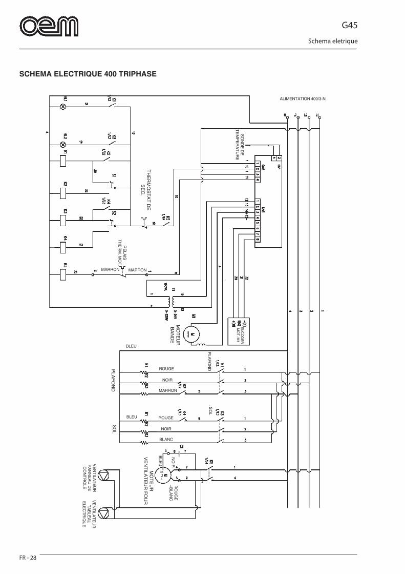
G45
FR - 28
Schema eletrique
SCHEMA ELECTRIQUE 400 TRIPHASE
ALIMENTATION 400/3-N
SO
ND
E D
E
TE
MP
ER
AT
UR
E
MARRON MARRON
RE
LAIS
T
HE
RM
. MO
T.
EN
CO
DE
R
MO
T. M
1
MO
TE
UR
B
AN
DE
TH
ER
MO
ST
AT
DE
S
EC
.
PLA
FO
ND
SO
L
ROUGE
NOIR
MARRON
ROUGE
NOIR
BLANC
BLEU
MO
TE
UR
V
EN
TILA
TE
UR
FO
UR
RO
UG
E+
BLA
NC
NO
IRVE
NT
ILAT
EU
R
PA
NN
EA
U D
E
CO
NT
RO
LE
BLE
U
VE
NT
ILAT
EU
R
TA
BLE
AU
E
LEC
TR
IQU
E
PLA
FO
ND
SO
L
BLEU
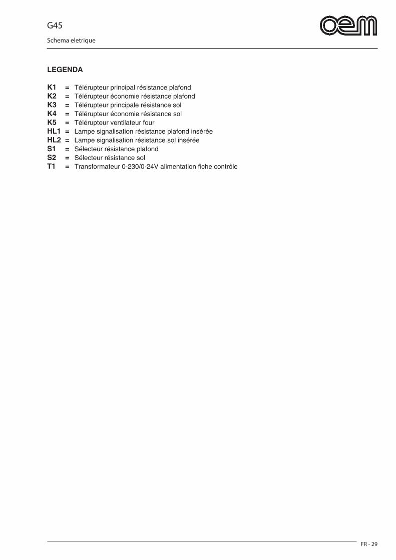
G45
FR - 29
Schema eletrique
LEGENDA
K1 = Télérupteur principal résistance plafondK2 = Télérupteur économie résistance plafondK3 = Télérupteur principale résistance solK4 = Télérupteur économie résistance solK5 = Télérupteur ventilateur fourHL1 = Lampe signalisation résistance plafond inséréeHL2 = Lampe signalisation résistance sol inséréeS1 = Sélecteur résistance plafondS2 = Sélecteur résistance solT1 = Transformateur 0-230/0-24V alimentation fi che contrôle
G45
Allgemeine Normen und Anmerkungen
DE - 1
DEUTSCH
ABSCHNITT .....................................................1Abschnitt für Fachtechniker und Benutzer1.1 ALLGEMEINE ANMERKUNGEN ........................Seite DE-31.2 BEZUGSNORMEN ..............................................Seite DE-41.3 BESCHREIBUNG DER SYMBOLE .....................Seite DE-41.4 ZUSAMMENSETZUNG DER MASCHINE ..........Seite DE-41.5 VORBEREITUNGEN ZU LASTEN DES EINKÄUFERS .....................................................Seite DE-51.6 NOTVERFAHREN IM BRANDFALL ...................Seite DE-51.7 EXPLOSIONSGEFAHR ......................................Seite DE-51.8 SCHALLDRUCKPEGEL .....................................Seite DE-5
ABSCHNITT .....................................................2Abschnitt für Fachtechniker- AUSSENMASSE ......................................................Seite DE-62.1 TECHNISCHE MERKMALE ..............................Seite DE-72.2 TRANSPORT ......................................................Seite DE-8 2.2.a Sendung .....................................................Seite DE-8 2.2.b Verpackungsheben ....................................Seite DE-8 2.2.c Einlagerung ................................................Seite DE-82.3 EINGANGSPRÜFUNG ........................................Seite DE-92.4 AUSPACKEN ......................................................Seite DE-92.5 IDENTIFIKATION DER KOMPONENTEN ........Seite DE-102.6 IDENTIFIKATION DER MASCHINE .................Seite DE-10
ABSCHNITT .....................................................3Abschnitt für Fachtechniker3.1 MASCHINENHEBEN ........................................Seite DE-113.2 ZUSAMMENBAU DER KOMPONENTEN .......Seite DE-113.3 ELEKTRISCHER ANSCHLUSS .......................Seite DE-12 3.3.a Elektrischer Ofenanschluss ......................Seite DE-12 3.3.b Äquipotentieller Anschluss .......................Seite DE-133.4 OFENPOSITIONIEREN ....................................Seite DE-133.5 ERSTES STARTEN ..........................................Seite DE-133.6 BANDDREHRICHTUNGSUMKEHREN ............Seite DE-143.7 INSTALLATION EINER WAHLFREIEN AUFLAGEEBENE .............................................Seite DE-143.8 INSTALLATION WAHLFREIER ROLLEN .........Seite DE-14
ABSCHNITT .....................................................4Abschnitt für Fachtechniker und Benutzer4.1 GEEIGNETE BENUTZUNG NANZEIGEN ........Seite DE-154.2 MISSBRÄUCHLICHE BENUTZUNG ...............Seite DE-154.3 SICHERHEITSSCHILDER ................................Seite DE-154.4 SICHERHEITSVORRICHTUNGEN ..................Seite DE-164.5 BENUTZERSTELLEN .......................................Seite DE-164.6 FLÄCHEN MIT RESTLICHEN GEFAHRLAGEN .................................................... Seite DE-164.7 GEFÄHRLICHE STELLEN ................................Seite DE-16
ABSCHNITT .....................................................5Abschnitt für Fachtechniker und Benutzer5.1 SCHALTTAFEL .................................................Seite DE-175.2 OFENBETRIEB .................................................Seite DE-185.3 EINGABEVERÄNDERUNG ..............................Seite DE-195.4 ÖFFNUNGSHÖHENVERSTELLUNG ...............Seite DE-195.5 ALARMUMSTÄNDE WÄHREND DES OFENBETRIEBS ...............................................Seite DE-20 5.5.a Alarm wegen beschädigtes oder ausgeschalteten Fühlers .........................Seite DE-20 5.5.b Bandmotoralarm .......................................Seite DE-20 5.5.c Alarmumstände wegen zu hoher Ofentemperatur ........................................Seite DE-205.6 AUSSCHALTUNG .............................................Seite DE-205.7 FEHLFUNKTION, URSACHEN UND ABHILFE ...........................................................Seite DE-21
ABSCHNITT .....................................................6Abschnitt für Fachtechniker und Benutzer6.1 ORDENTLICHE UND EINGEPLANTE INSTANDHALTUNG ........................................Seite DE-22 6.1.a Allgemeine daten ....................................Seite DE-22 6.1.b Ordentliche instandhaltung ....................Seite DE-22 6.1.b - a Aussenreinigung ...............................Seite DE-22 6.1.b - b Innenreinigung des Backofens ........Seite DE-22 6.1.c Geplante instandhaltungsverfahren .......Seite DE-24 6.1.c - a Alle 2 Jahre ......................................Seite DE-24 6.1.d instandhaltungsverfahren im bedarsfall ................................................Seite DE-24 6.1.d - a Bandspannung ..................................Seite DE-24
ABSCHNITT .....................................................7Abschnitt für Fachtechniker7.1 DEMONTAGE DER MASCHINE .......................Seite DE-257.2 MASCHINENABBRUCH ...................................Seite DE-257.3 SCHADSTOFFENTSORGUNG ........................Seite DE-25
SCHALTPLAN 220 EINPHASIG ..............................Seite DE-26SCHALTPLAN 230 DREIPHASIG ............................Seite DE-27SCHALTPLAN 400 DREIPHASIG ............................Seite DE-28
LEGENDE ...............................................................Seite DE-29

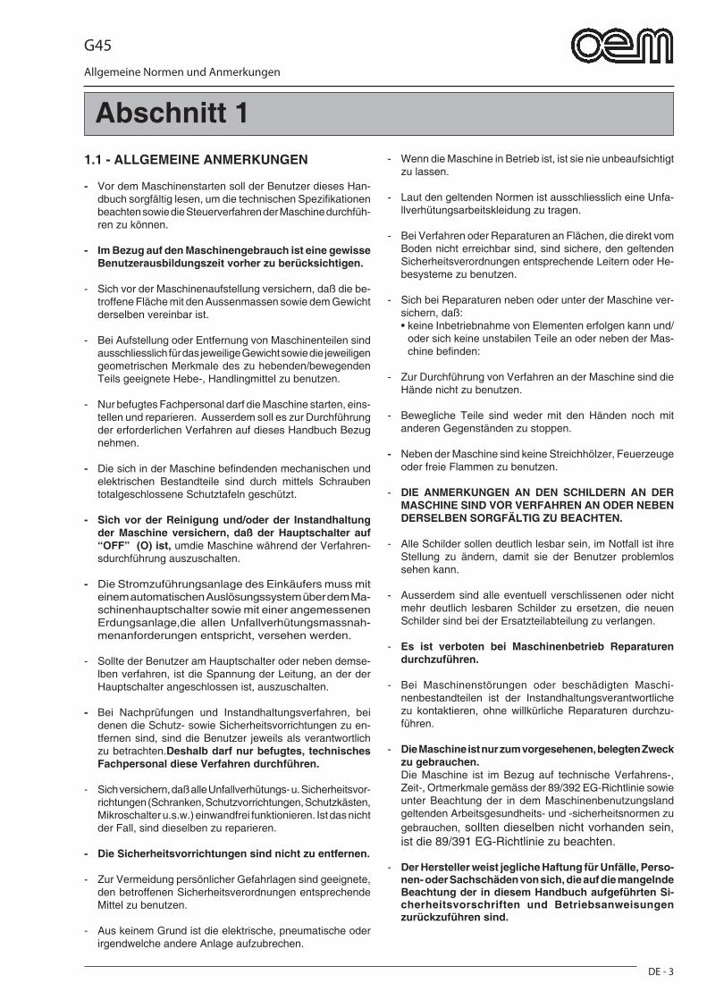
G45
Allgemeine Normen und Anmerkungen
DE - 3
Abschnitt 11.1 - ALLGEMEINE ANMERKUNGEN
- Vor dem Maschinenstarten soll der Benutzer dieses Han-dbuch sorgfältig lesen, um die technischen Spezifi kationen beachten sowie die Steuerverfahren der Maschine durchfüh-ren zu können.
- Im Bezug auf den Maschinengebrauch ist eine gewisse Benutzerausbildungszeit vorher zu berücksichtigen.
- Sich vor der Maschinenaufstellung versichern, daß die be-troffene Fläche mit den Aussenmassen sowie dem Gewicht derselben vereinbar ist.
- Bei Aufstellung oder Entfernung von Maschinenteilen sind ausschliesslich für das jeweilige Gewicht sowie die jeweiligen geometrischen Merkmale des zu hebenden/bewegenden Teils geeignete Hebe-, Handlingmittel zu benutzen.
- Nur befugtes Fachpersonal darf die Maschine starten, eins-tellen und reparieren. Ausserdem soll es zur Durchführung der erforderlichen Verfahren auf dieses Handbuch Bezug nehmen.
- Die sich in der Maschine befi ndenden mechanischen und elektrischen Bestandteile sind durch mittels Schrauben totalgeschlossene Schutztafeln geschützt.
- Sich vor der Reinigung und/oder der Instandhaltung der Maschine versichern, daß der Hauptschalter auf “OFF” (O) ist, umdie Maschine während der Verfahren-sdurchführung auszuschalten.
- Die Stromzuführungsanlage des Einkäufers muss mit einem automatischen Auslösungssystem über dem Ma-schinenhauptschalter sowie mit einer angemessenen Erdungsanlage,die allen Unfallverhütungsmassnah-menanforderungen entspricht, versehen werden.
- Sollte der Benutzer am Hauptschalter oder neben demse-lben verfahren, ist die Spannung der Leitung, an der der Hauptschalter angeschlossen ist, auszuschalten.
- Bei Nachprüfungen und Instandhaltungsverfahren, bei denen die Schutz- sowie Sicherheitsvorrichtungen zu en-tfernen sind, sind die Benutzer jeweils als verantwortlich zu betrachten.Deshalb darf nur befugtes, technisches Fachpersonal diese Verfahren durchführen.
- Sich versichern, daß alle Unfallverhütungs- u. Sicherheitsvor-richtungen (Schranken, Schutzvorrichtungen, Schutzkästen, Mikroschalter u.s.w.) einwandfrei funktionieren. Ist das nicht der Fall, sind dieselben zu reparieren.
- Die Sicherheitsvorrichtungen sind nicht zu entfernen.
- Zur Vermeidung persönlicher Gefahrlagen sind geeignete, den betroffenen Sicherheitsverordnungen entsprechende Mittel zu benutzen.
- Aus keinem Grund ist die elektrische, pneumatische oder irgendwelche andere Anlage aufzubrechen.
- Wenn die Maschine in Betrieb ist, ist sie nie unbeaufsichtigt zu lassen.
- Laut den geltenden Normen ist ausschliesslich eine Unfa-llverhütungsarbeitskleidung zu tragen.
- Bei Verfahren oder Reparaturen an Flächen, die direkt vom Boden nicht erreichbar sind, sind sichere, den geltenden Sicherheitsverordnungen entsprechende Leitern oder He-besysteme zu benutzen.
- Sich bei Reparaturen neben oder unter der Maschine ver-sichern, daß:
• keine Inbetriebnahme von Elementen erfolgen kann und/oder sich keine unstabilen Teile an oder neben der Mas-chine befi nden:
- Zur Durchführung von Verfahren an der Maschine sind die Hände nicht zu benutzen.
- Bewegliche Teile sind weder mit den Händen noch mit anderen Gegenständen zu stoppen.
- Neben der Maschine sind keine Streichhölzer, Feuerzeuge oder freie Flammen zu benutzen.
- DIE ANMERKUNGEN AN DEN SCHILDERN AN DER MASCHINE SIND VOR VERFAHREN AN ODER NEBEN DERSELBEN SORGFÄLTIG ZU BEACHTEN.
- Alle Schilder sollen deutlich lesbar sein, im Notfall ist ihre Stellung zu ändern, damit sie der Benutzer problemlos sehen kann.
- Ausserdem sind alle eventuell verschlissenen oder nicht mehr deutlich lesbaren Schilder zu ersetzen, die neuen Schilder sind bei der Ersatzteilabteilung zu verlangen.
- Es ist verboten bei Maschinenbetrieb Reparaturen durchzuführen.
- Bei Maschinenstörungen oder beschädigten Maschi-nenbestandteilen ist der Instandhaltungsverantwortliche zu kontaktieren, ohne willkürliche Reparaturen durchzu-führen.
- Die Maschine ist nur zum vorgesehenen, belegten Zweck zu gebrauchen.
Die Maschine ist im Bezug auf technische Verfahrens-, Zeit-, Ortmerkmale gemäss der 89/392 EG-Richtlinie sowie unter Beachtung der in dem Maschinenbenutzungsland geltenden Arbeitsgesundheits- und -sicherheitsnormen zu gebrauchen, sollten dieselben nicht vorhanden sein, ist die 89/391 EG-Richtlinie zu beachten.
- Der Hersteller weist jegliche Haftung für Unfälle, Perso-nen- oder Sachschäden von sich, die auf die mangelnde Beachtung der in diesem Handbuch aufgeführten Si-cherheitsvorschriften und Betriebsanweisungen zurückzuführen sind.
G45
Allgemeine Normen und Anmerkungen
DE - 4
- DIESE SICHERHEITSNORMEN ERGÄNZEN DIE JEWEILS ÖRTLICHEN GELTENDEN SICHERHEITSNORMEN.
- Rasch vorbereitete oder Notreparaturen sind NIE dur-chzuführen, da dieselben den Maschinenbetrieb sowie die Sicherheitsumstände des Benutzers beeinträchtigen könnten.
- IM ZWEIFELSFALLE IST FACHPERSONAL ZU KON-TAKTIEREN.
- BEI AUFBRECHEN DER MASCHINE IM ELEKTRISCHEN, ELEKTRONISCHEN ODER MECHANISCHEN BEREICH SOWIE BEI NACHLÄSSIGEM MASCHINENGEBRAUCH LEHNT DER HERSTELLER IRGENDWELCHE HAFTUNG AB, DA GGF. IST NUR DER BENUTZER ALS VERANT-WORTLICH ZU BETRACHTEN.
1.2 - BEZUGSNORMEN- Die Maschine und ihre Sicherheitsvorrichtungen sind
nach den Normen, die in der Konformitätserklärung enthalten sind, gebaut worden.
1.3 - BESCHREIBUNG DER SYMBOLEViele Unfälle entstehen aus einer ungenügenden Kenntnis sowie aus der Nichtbeachtung der Si-cherheitsregeln während des Maschinenbetriebs und der Instandhaltungsverfahren.Zur Vermeidung von Unfällen sind alle Vorsichts-massnahmen und Anmerkungen in diesem Han-dbuch sowie an den Schildern an der Maschine zu lesen, zu verstehen und zu beachten.Zur Identifi kation der sich in diesem Handbuch be-fi ndenden Sicherheitsnachrichten werden folgende Symbole benutzt:
GEFAHRLAGEDieses Symbol wird bei den Sicherheitsnachrichten des Handbuchs benutzt, wenn potentielle sowie Schwerverletzungs- oder Todgefahrlagen vorhan-den sind.
ACHTUNGDieses Symbol wird auch bei den Sicherheitsna-chrichten des Handbuchs benutzt, wo Gefahrlagen, bei denen kleine Verletzungen oder Schäden entste-hen können, benutzt.Die Nachricht kann auch nur bei Gefahrlagen, die Maschinenbeschädigungen verursachen können, benutzt werden.
WICHTIGDieses Symbol ist als Vorsichtsmassnahme zu betrachten, um Verfahren, die die Lebensdauer der Maschine beeinträchtigen könnten, zu vermeiden, es wird auch bei wichtigen Hinweisen an den Benutzer verwendet.
GEFAHRLAGE
Aus Deutlichkeitsgründen wird die Maschine in einigen Abbildungen dieses Handbuchs ohne Schut-zvorrichtungen gezeigt. DIE MASCHINE IST NIE OHNE EINGEBAUTE SCHUTZVORRICHTUNGEN ZU GEBRAUCHEN.
1.4 - ZUSAMMENSETZUNG DER MASCHINEDie Maschinen des Herstellers sind das Ergebnis einer lan-gjährigen Erfahrung.
• Öfen für konvektive Erwärmung mit einer einzelnen Kammer, zwei oder drei Kammern; sie bestehen aus einer angemessen isolierten Edelstahlaussen-struktur, einem feinmaschigen Edelstahlförderband sowie aus einem mit Widerständen versehenen Konvektionsbackkammersystem.
Warmluftrücklauf durch Lüfter.• Der/Die Backofen/-öfen befi nden sich an einer Trag-
struktur.
G45
Allgemeine Normen und Anmerkungen
DE - 5
1.5 - VORBEREITUNGEN ZU LASTEN DES EINKÄUFERS
a) Vorbereitung des Anlagenaufstellungsorts.• Der Einkäufer soll laut Hinweisen in dem Abschnitt
"Maschinenaufstellung" eine Stützenfl äche vorberei-ten.
b) Elektrische Anschlussvorbereitung.• Die Stromzuführungsanlage soll den geltenden
Normen des Bestimmungslands entsprechen sowie mit einer angemessenen Erdungsanlage versehen werden.
• An der Zuführungsleitung an der oberen Seite der Maschine ist eine allpolige Trennungsvorrichtung anzubringen.
• Die elektrischen Speisekabel sind aufgrund des höchsten, von der Maschine benötigten Stromwerts zu dimensionieren, sodaß ein eventueller Stromabfall bei Volllast 2% unter-schreitet.
c) Mittelleiter• Die Anlage ist mit Mittelleiter versehen, daher ist
eine dazu bestimmte, nach den geltenden Richtlinien identifi zierte Klemme vorbereitet worden.
1.6 - NOTVERFAHREN IM BRANDFALL
a) Im Brandfall ist der Hauptschalter und dadurch die Maschinenspannung auszuschalten.
b) Zur Brandlöschung sind dafür geeignete Löscher zu benutzen.
GEFAHRLAGE Es ist verboten unter Spannungsumständen mit Wasser den Brand zu löschen.
1.7 - EXPLOSIONSGEFAHR• Die Maschine ist für Benutzung in explosionsgefährli-
chen Räumen nicht geeignet.
1.8 - SCHALLDRUCKPEGELGHIBLI G45-Öfen sind so gebaut worden, daß der fort-dauernde gleichwertige gewogene A-Schalldruckpegel (dB) die maximal zulässige 70dB-Grenze unterschrei-tet.
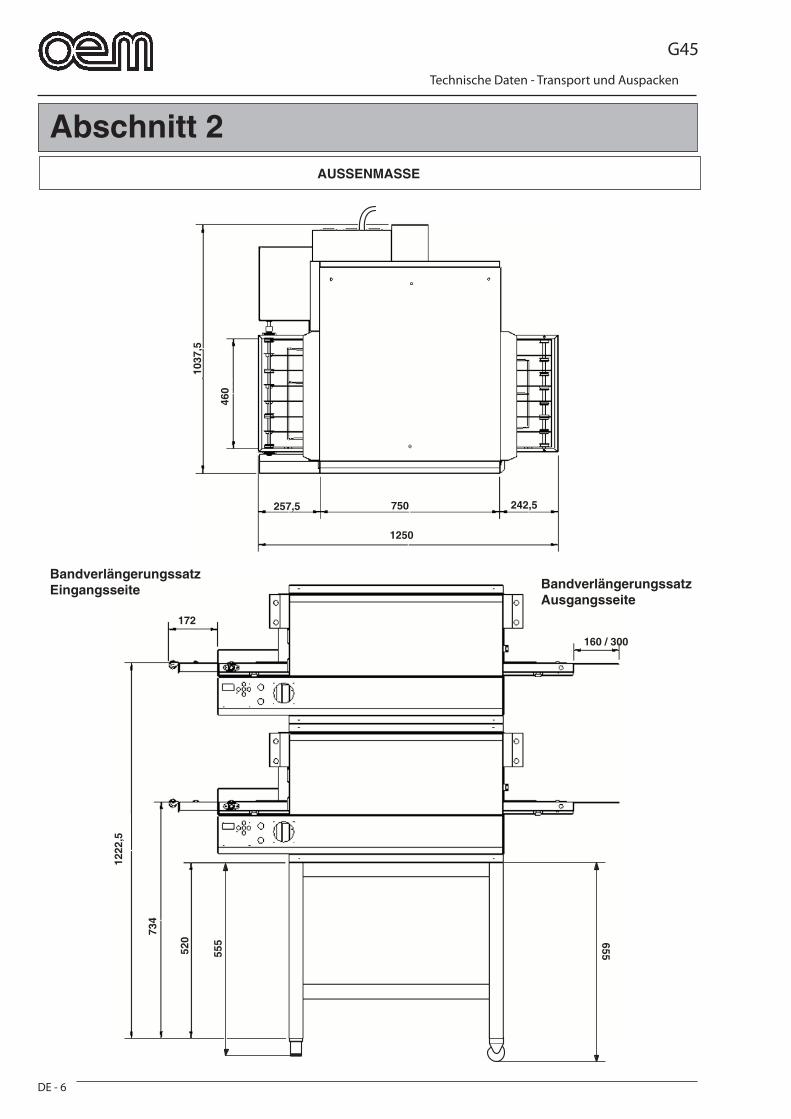
G45
Technische Daten - Transport und Auspacken
DE - 6
1037
,5
460
750
1250
257,5 242,5
1222
,5
734
520
555 655
160 / 300
172
Abschnitt 2AUSSENMASSE
BandverlängerungssatzEingangsseite Bandverlängerungssatz
Ausgangsseite
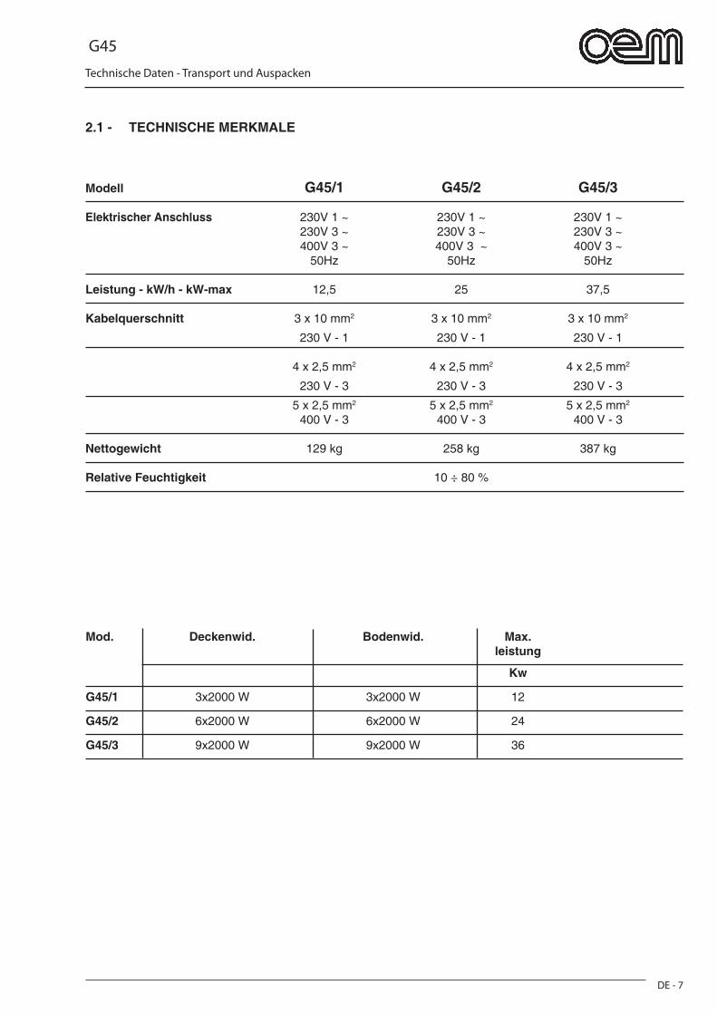
G45
Technische Daten - Transport und Auspacken
DE - 7
2.1 - TECHNISCHE MERKMALE
Modell G45/1 G45/2 G45/3
Elektrischer Anschluss 230V 1 ~ 230V 1 ~ 230V 1 ~ 230V 3 ~ 230V 3 ~ 230V 3 ~ 400V 3 ~ 400V 3 ~ 400V 3 ~ 50Hz 50Hz 50Hz
Leistung - kW/h - kW-max 12,5 25 37,5
Kabelquerschnitt 3 x 10 mm2 3 x 10 mm2 3 x 10 mm2
230 V - 1 230 V - 1 230 V - 1
4 x 2,5 mm2 4 x 2,5 mm2 4 x 2,5 mm2
230 V - 3 230 V - 3 230 V - 3
5 x 2,5 mm2 5 x 2,5 mm2 5 x 2,5 mm2
400 V - 3 400 V - 3 400 V - 3
Nettogewicht 129 kg 258 kg 387 kg
Relative Feuchtigkeit 10 ÷ 80 %
Mod. Deckenwid. Bodenwid. Max. leistung
Kw
G45/1 3x2000 W 3x2000 W 12
G45/2 6x2000 W 6x2000 W 24
G45/3 9x2000 W 9x2000 W 36
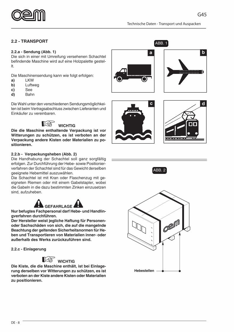
G45
Technische Daten - Transport und Auspacken
DE - 8
a b
c d
FIG. 2
FIG. 1FIG. 1
FIG. 2
2.2 - TRANSPORT
2.2.a - Sendung (Abb. 1)Die sich in einer mit Umreifung versehenen Schachtel befi ndende Maschine wird auf eine Holzpalette gestel-lt.
Die Maschinensendung kann wie folgt erfolgen:a) LKWb) Luftwegc) Seed) Bahn
Die Wahl unter den verschiedenen Sendungsmöglichkei-ten ist beim Vertragsabschluss zwischen Lieferanten und Einkäufer zu vereinbaren.
WICHTIGDie die Maschine enthaltende Verpackung ist vor Witterungen zu schützen, es ist verboten an der Verpackung andere Kisten oder Materialien zu po-sitionieren.
2.2.b - Verpackungsheben (Abb. 2)Die Handhabung der Schachtel soll ganz sorgfältig erfolgen. Zur Durchführung der Hebe- sowie Positionier-verfahren der Schachtel sind für das Gewicht derselben geeignete Hebemittel auszuwählen.Die Schachtel ist mit Kran oder Flaschenzug mit ge-eigneten Riemen oder mit einem Gabelstapler, wobei die Gabeln in die dazu bestimmten Zinken einzusetzen sind, aufzuheben.
GEFAHRLAGE Nur befugtes Fachpersonal darf Hebe- und Handlin-gverfahren durchführen.Der Hersteller weist jegliche Haftung für Personen- oder Sachschäden von sich, die auf die mangelnde Beachtung der geltenden Sicherheitsnormen für He-ben und Transportieren von Materialien inner- oder außerhalb des Werks zurückzuführen sind.
2.2.c - Einlagerung
WICHTIGDie Kiste, die die Maschine enthält, ist bei Einlage-rung derselben vor Witterungen zu schützen, es ist verboten an der Kiste andere Kisten oder Materialien zu positionieren.
ABB. 1
ABB. 2
Hebestellen
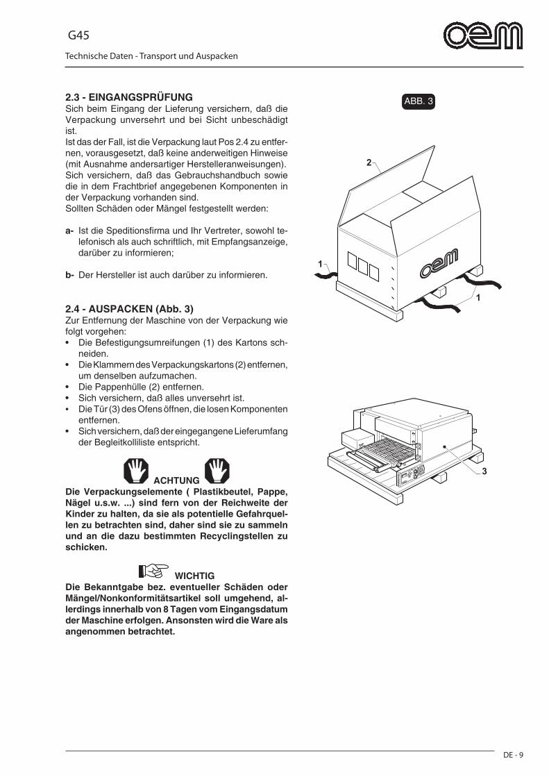
G45
Technische Daten - Transport und Auspacken
DE - 9
FIG. 3
1
1
2
3
2.3 - EINGANGSPRÜFUNGSich beim Eingang der Lieferung versichern, daß die Verpackung unversehrt und bei Sicht unbeschädigt ist.Ist das der Fall, ist die Verpackung laut Pos 2.4 zu entfer-nen, vorausgesetzt, daß keine anderweitigen Hinweise (mit Ausnahme andersartiger Herstelleranweisungen).Sich versichern, daß das Gebrauchshandbuch sowie die in dem Frachtbrief angegebenen Komponenten in der Verpackung vorhanden sind. Sollten Schäden oder Mängel festgestellt werden:
a- Ist die Speditionsfi rma und Ihr Vertreter, sowohl te-lefonisch als auch schriftlich, mit Empfangsanzeige, darüber zu informieren;
b- Der Hersteller ist auch darüber zu informieren.
2.4 - AUSPACKEN (Abb. 3)Zur Entfernung der Maschine von der Verpackung wie folgt vorgehen:• Die Befestigungsumreifungen (1) des Kartons sch-
neiden.• Die Klammern des Verpackungskartons (2) entfernen,
um denselben aufzumachen.• Die Pappenhülle (2) entfernen.• Sich versichern, daß alles unversehrt ist.• Die Tür (3) des Ofens öffnen, die losen Komponenten
entfernen.• Sich versichern, daß der eingegangene Lieferumfang
der Begleitkolliliste entspricht.
ACHTUNG Die Verpackungselemente ( Plastikbeutel, Pappe, Nägel u.s.w. ...) sind fern von der Reichweite der Kinder zu halten, da sie als potentielle Gefahrquel-len zu betrachten sind, daher sind sie zu sammeln und an die dazu bestimmten Recyclingstellen zu schicken.
WICHTIGDie Bekanntgabe bez. eventueller Schäden oder Mängel/Nonkonformitätsartikel soll umgehend, al-lerdings innerhalb von 8 Tagen vom Eingangsdatum der Maschine erfolgen. Ansonsten wird die Ware als angenommen betrachtet.
ABB. 3
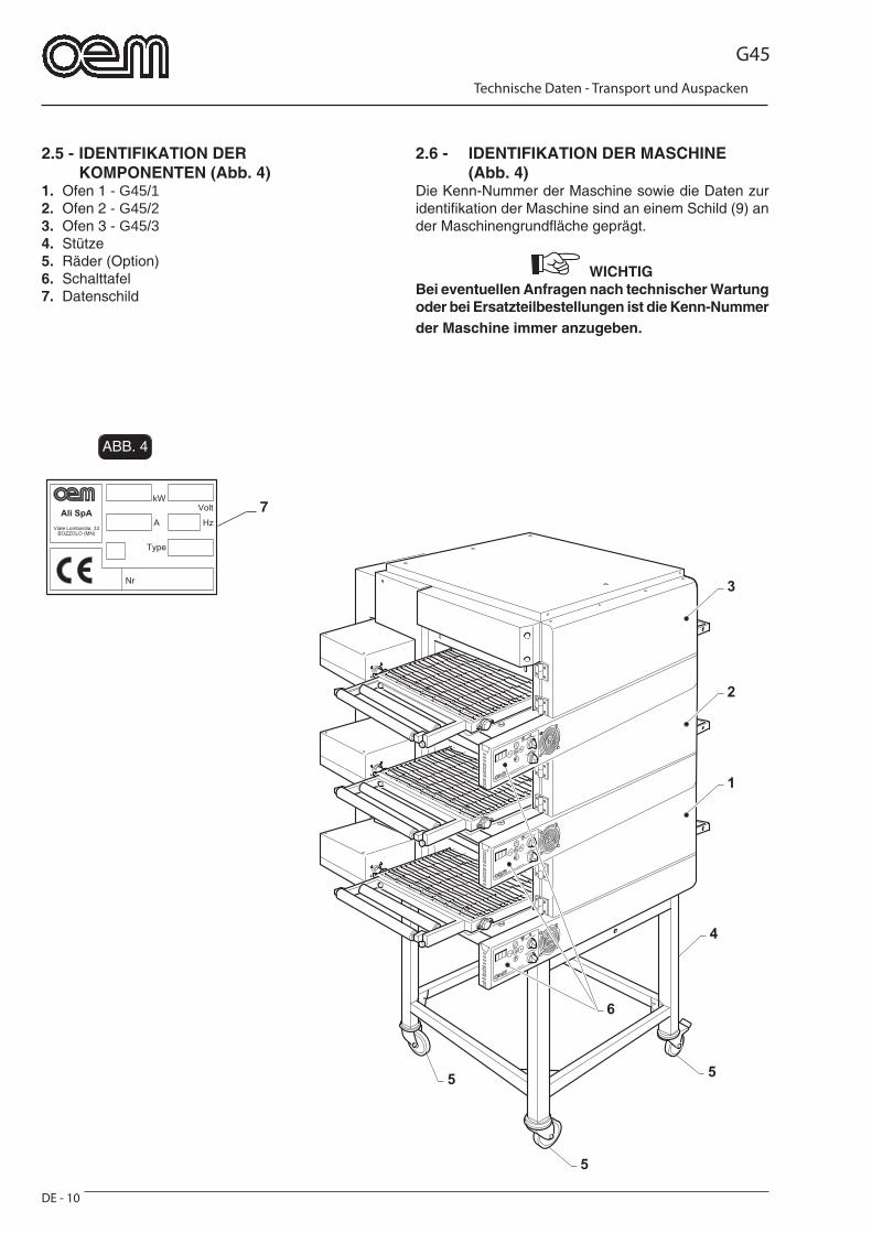
G45
Technische Daten - Transport und Auspacken
DE - 10
FIG. 4
7
5
55
4
6
1
2
3
2.5 - IDENTIFIKATION DER KOMPONENTEN (Abb. 4)
1. Ofen 1 - G45/12. Ofen 2 - G45/2 3. Ofen 3 - G45/34. Stütze5. Räder (Option)6. Schalttafel7. Datenschild
2.6 - IDENTIFIKATION DER MASCHINE (Abb. 4)Die Kenn-Nummer der Maschine sowie die Daten zur identifi kation der Maschine sind an einem Schild (9) an der Maschinengrundfl äche geprägt.
WICHTIG Bei eventuellen Anfragen nach technischer Wartung oder bei Ersatzteilbestellungen ist die Kenn-Nummer der Maschine immer anzugeben.
ABB. 4
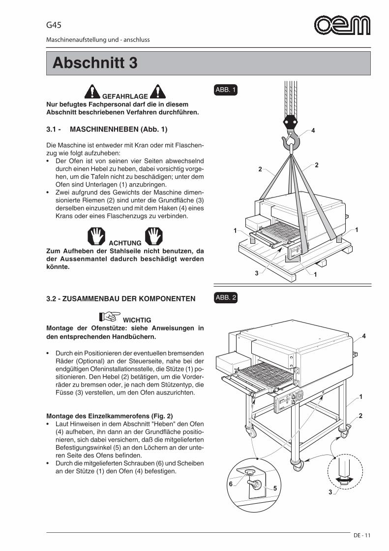
G45
DE - 11
Maschinenaufstellung und - anschluss
FIG. 2
FIG. 1
4
22
1 1
13
1
3
2
4
65
GEFAHRLAGE Nur befugtes Fachpersonal darf die in diesem Abschnitt beschriebenen Verfahren durchführen.
3.1 - MASCHINENHEBEN (Abb. 1)
Die Maschine ist entweder mit Kran oder mit Flaschen-zug wie folgt aufzuheben:• Der Ofen ist von seinen vier Seiten abwechselnd
durch einen Hebel zu heben, dabei vorsichtig vorge-hen, um die Tafeln nicht zu beschädigen; unter dem Ofen sind Unterlagen (1) anzubringen.
• Zwei aufgrund des Gewichts der Maschine dimen-sionierte Riemen (2) sind unter die Grundfl äche (3) derselben einzusetzen und mit dem Haken (4) eines Krans oder eines Flaschenzugs zu verbinden.
ACHTUNG Zum Aufheben der Stahlseile nicht benutzen, da der Aussenmantel dadurch beschädigt werden könnte.
3.2 - ZUSAMMENBAU DER KOMPONENTEN
WICHTIG Montage der Ofenstütze: siehe Anweisungen in den entsprechenden Handbüchern.
• Durch ein Positionieren der eventuellen bremsenden Räder (Optional) an der Steuerseite, nahe bei der endgültigen Ofeninstallationsstelle, die Stütze (1) po-sitionieren. Den Hebel (2) betätigen, um die Vorder-räder zu bremsen oder, je nach dem Stützentyp, die Füsse (3) verstellen, um den Ofen auszurichten.
Montage des Einzelkammerofens (Fig. 2)• Laut Hinweisen in dem Abschnitt "Heben" den Ofen
(4) aufheben, ihn dann an der Grundfl äche positio-nieren, sich dabei versichern, daß die mitgelieferten Befestigungswinkel (5) an den Löchern an der unte-ren Seite des Ofens befi nden.
• Durch die mitgelieferten Schrauben (6) und Scheiben an der Stütze (1) den Ofen (4) befestigen.
Abschnitt 3
ABB. 1
ABB. 2
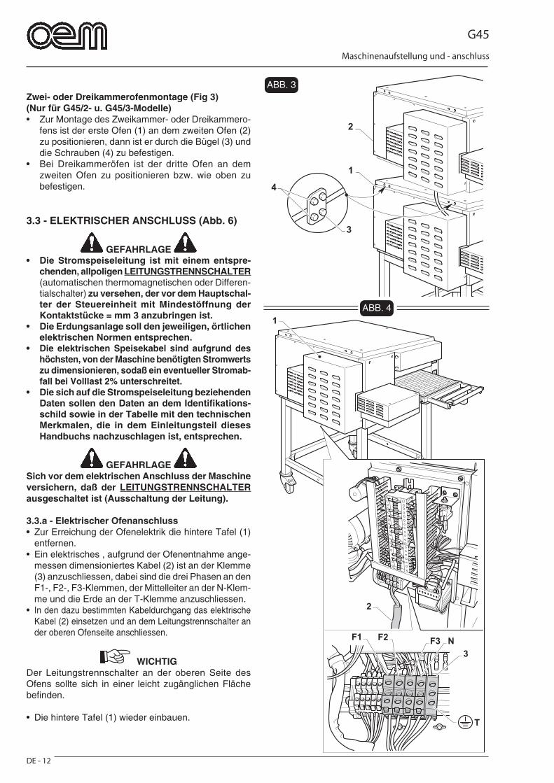
G45
DE - 12
Maschinenaufstellung und - anschluss
FIG. 3
FIG. 41
2
T
F3 N
3
F2F1
1
2
3
4
Zwei- oder Dreikammerofenmontage (Fig 3)(Nur für G45/2- u. G45/3-Modelle)• Zur Montage des Zweikammer- oder Dreikammero-
fens ist der erste Ofen (1) an dem zweiten Ofen (2) zu positionieren, dann ist er durch die Bügel (3) und die Schrauben (4) zu befestigen.
• Bei Dreikammeröfen ist der dritte Ofen an dem zweiten Ofen zu positionieren bzw. wie oben zu befestigen.
3.3 - ELEKTRISCHER ANSCHLUSS (Abb. 6)
GEFAHRLAGE • Die Stromspeiseleitung ist mit einem entspre-
chenden, allpoligen LEITUNGSTRENNSCHALTER (automatischen thermomagnetischen oder Differen-tialschalter) zu versehen, der vor dem Hauptschal-ter der Steuereinheit mit Mindestöffnung der Kontaktstücke = mm 3 anzubringen ist.
• Die Erdungsanlage soll den jeweiligen, örtlichen elektrischen Normen entsprechen.
• Die elektrischen Speisekabel sind aufgrund des höchsten, von der Maschine benötigten Stromwerts zu dimensionieren, sodaß ein eventueller Stromab-fall bei Volllast 2% unterschreitet.
• Die sich auf die Stromspeiseleitung beziehenden Daten sollen den Daten an dem Identifi kations-schild sowie in der Tabelle mit den technischen Merkmalen, die in dem Einleitungsteil dieses Handbuchs nachzuschlagen ist, entsprechen.
GEFAHRLAGE Sich vor dem elektrischen Anschluss der Maschine versichern, daß der LEITUNGSTRENNSCHALTER ausgeschaltet ist (Ausschaltung der Leitung).
3.3.a - Elektrischer Ofenanschluss• Zur Erreichung der Ofenelektrik die hintere Tafel (1)
entfernen.• Ein elektrisches , aufgrund der Ofenentnahme ange-
messen dimensioniertes Kabel (2) ist an der Klemme (3) anzuschliessen, dabei sind die drei Phasen an den F1-, F2-, F3-Klemmen, der Mittelleiter an der N-Klem-me und die Erde an der T-Klemme anzuschliessen.
• In den dazu bestimmten Kabeldurchgang das elektrische Kabel (2) einsetzen und an dem Leitungstrennschalter an der oberen Ofenseite anschliessen.
WICHTIGDer Leitungstrennschalter an der oberen Seite des Ofens sollte sich in einer leicht zugänglichen Fläche befi nden.
• Die hintere Tafel (1) wieder einbauen.
ABB. 3
ABB. 4
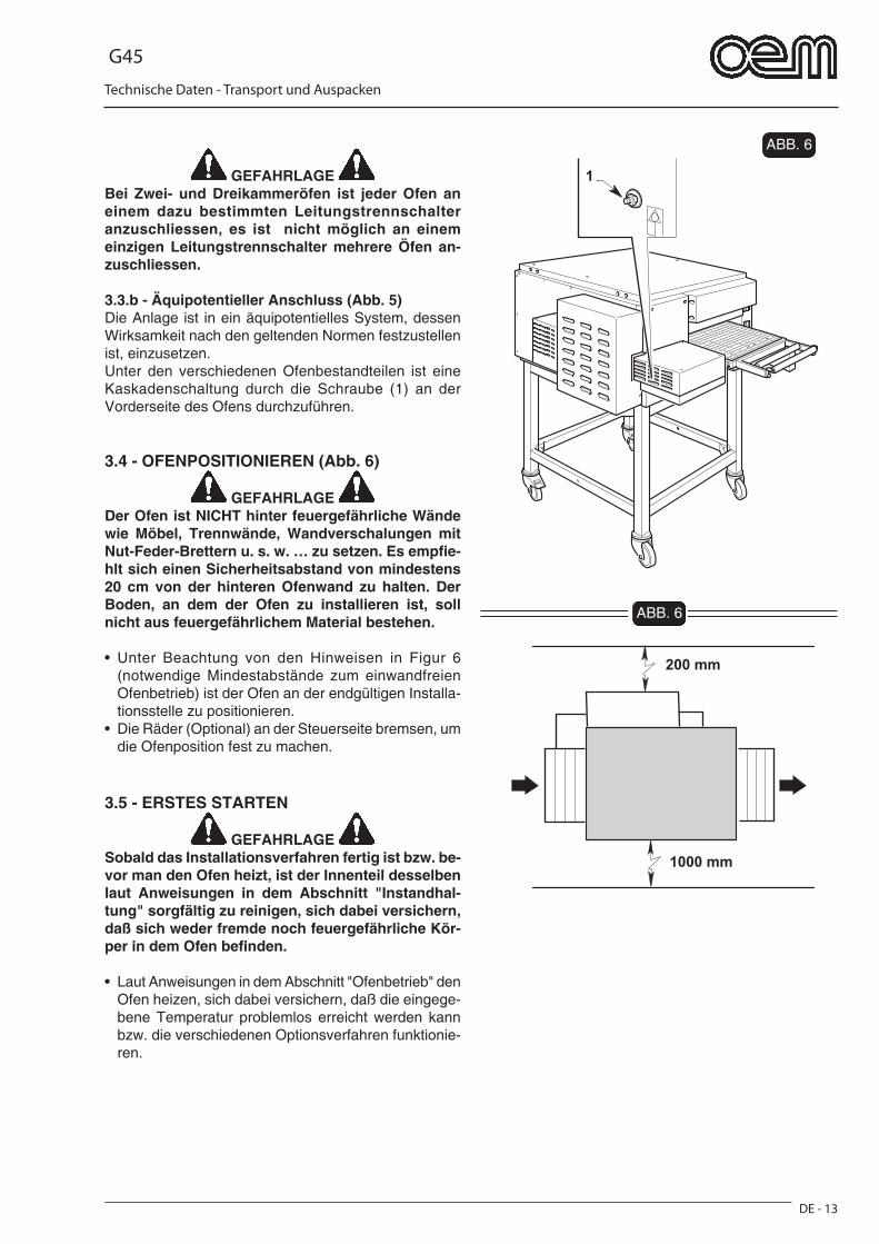
G45
Technische Daten - Transport und Auspacken
DE - 13
FIG. 5
1
FIG. 6
200 mm
1000 mm
GEFAHRLAGE Bei Zwei- und Dreikammeröfen ist jeder Ofen an einem dazu bestimmten Leitungstrennschalter anzuschliessen, es ist nicht möglich an einem einzigen Leitungstrennschalter mehrere Öfen an-zuschliessen.
3.3.b - Äquipotentieller Anschluss (Abb. 5)Die Anlage ist in ein äquipotentielles System, dessen Wirksamkeit nach den geltenden Normen festzustellen ist, einzusetzen.Unter den verschiedenen Ofenbestandteilen ist eine Kaskadenschaltung durch die Schraube (1) an der Vorderseite des Ofens durchzuführen.
3.4 - OFENPOSITIONIEREN (Abb. 6)
GEFAHRLAGE Der Ofen ist NICHT hinter feuergefährliche Wände wie Möbel, Trennwände, Wandverschalungen mit Nut-Feder-Brettern u. s. w. … zu setzen. Es empfi e-hlt sich einen Sicherheitsabstand von mindestens 20 cm von der hinteren Ofenwand zu halten. Der Boden, an dem der Ofen zu installieren ist, soll nicht aus feuergefährlichem Material bestehen.
• Unter Beachtung von den Hinweisen in Figur 6 (notwendige Mindestabstände zum einwandfreien Ofenbetrieb) ist der Ofen an der endgültigen Installa-tionsstelle zu positionieren.
• Die Räder (Optional) an der Steuerseite bremsen, um die Ofenposition fest zu machen.
3.5 - ERSTES STARTEN
GEFAHRLAGE Sobald das Installationsverfahren fertig ist bzw. be-vor man den Ofen heizt, ist der Innenteil desselben laut Anweisungen in dem Abschnitt "Instandhal-tung" sorgfältig zu reinigen, sich dabei versichern, daß sich weder fremde noch feuergefährliche Kör-per in dem Ofen befi nden.
• Laut Anweisungen in dem Abschnitt "Ofenbetrieb" den Ofen heizen, sich dabei versichern, daß die eingege-bene Temperatur problemlos erreicht werden kann bzw. die verschiedenen Optionsverfahren funktionie-ren.
ABB. 6
ABB. 6
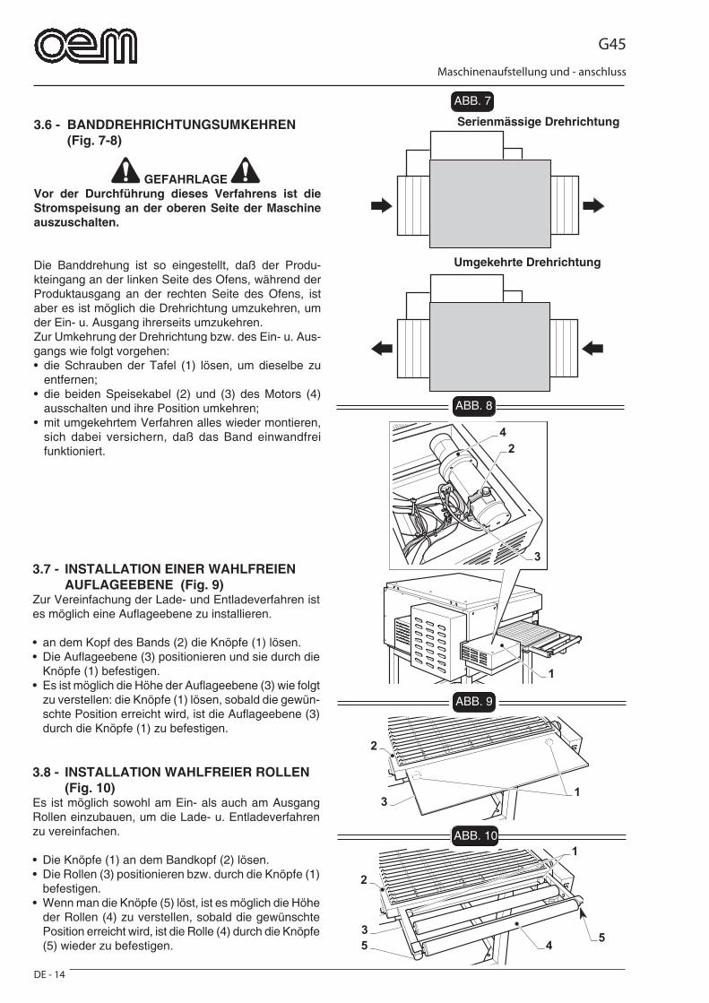
G45
DE - 14
Maschinenaufstellung und - anschluss
FIG. 7
FIG. 8
FIG. 9
4
2
3
1
45
3
2
1
5
2
13
FIG. 10
3.6 - BANDDREHRICHTUNGSUMKEHREN (Fig. 7-8)
GEFAHRLAGE Vor der Durchführung dieses Verfahrens ist die Stromspeisung an der oberen Seite der Maschine auszuschalten.
Die Banddrehung ist so eingestellt, daß der Produ-kteingang an der linken Seite des Ofens, während der Produktausgang an der rechten Seite des Ofens, ist aber es ist möglich die Drehrichtung umzukehren, um der Ein- u. Ausgang ihrerseits umzukehren.Zur Umkehrung der Drehrichtung bzw. des Ein- u. Aus-gangs wie folgt vorgehen:• die Schrauben der Tafel (1) lösen, um dieselbe zu
entfernen;• die beiden Speisekabel (2) und (3) des Motors (4)
ausschalten und ihre Position umkehren;• mit umgekehrtem Verfahren alles wieder montieren,
sich dabei versichern, daß das Band einwandfrei funktioniert.
Umgekehrte Drehrichtung
Serienmässige Drehrichtung
3.7 - INSTALLATION EINER WAHLFREIEN AUFLAGEEBENE (Fig. 9)Zur Vereinfachung der Lade- und Entladeverfahren ist es möglich eine Aufl ageebene zu installieren.
• an dem Kopf des Bands (2) die Knöpfe (1) lösen.• Die Aufl ageebene (3) positionieren und sie durch die
Knöpfe (1) befestigen.• Es ist möglich die Höhe der Aufl ageebene (3) wie folgt
zu verstellen: die Knöpfe (1) lösen, sobald die gewün-schte Position erreicht wird, ist die Aufl ageebene (3) durch die Knöpfe (1) zu befestigen.
3.8 - INSTALLATION WAHLFREIER ROLLEN (Fig. 10)Es ist möglich sowohl am Ein- als auch am Ausgang Rollen einzubauen, um die Lade- u. Entladeverfahren zu vereinfachen.
• Die Knöpfe (1) an dem Bandkopf (2) lösen.• Die Rollen (3) positionieren bzw. durch die Knöpfe (1)
befestigen.• Wenn man die Knöpfe (5) löst, ist es möglich die Höhe
der Rollen (4) zu verstellen, sobald die gewünschte Position erreicht wird, ist die Rolle (4) durch die Knöpfe (5) wieder zu befestigen.
ABB. 7
ABB. 8
ABB. 9
ABB. 10
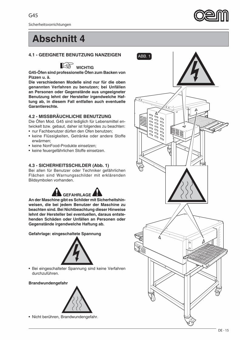
G45
DE - 15
Sicherheitsvorrichtungen
FIG. 14.1 - GEEIGNETE BENUTZUNG NANZEIGEN
WICHTIG G45-Öfen sind professionelle Öfen zum Backen von Pizzen u. ä.Die verschiedenen Modelle sind nur für die oben genannten Verfahren zu benutzen; bei Unfällen an Personen oder Gegenstände aus ungeeigneter Benutzung lehnt der Hersteller irgendwelche Haf-tung ab, in diesem Fall entfallen auch eventuelle Garantierechte.
4.2 - MISSBRÄUCHLICHE BENUTZUNGDie Öfen Mod. G45 sind lediglich für Lebensmittel en-twickelt bzw. gebaut, daher ist folgendes zu beachten:• nur Fachbenutzer dürfen den Ofen benutzen;• keine Flüssigkeiten, Getränke oder andere Stoffe
erwärmen;• keine NonFood-Produkte einsetzen;• keine feuergefährlichen Stoffe einsetzen.
4.3 - SICHERHEITSSCHILDER (Abb. 1)Bei allen für Benutzer oder Techniker gefährlichen Flächen sind Warnungsschilder mit erklärenden Bildsymbolen vorhanden.
GEFAHRLAGE An der Maschine gibt es Schilder mit Sicherheitshin-weisen, die bei jedem Benutzer der Maschine zu beachten sind. Bei Nichtbeachtung dieser Hinweise lehnt der Hersteller bei eventuellen, daraus entste-henden Schäden oder Unfällen an Personen oder Gegenstände irgendwelche Haftung ab.
Gefahrlage: eingeschaltete Spannung
• Bei eingeschalteter Spannung sind keine Verfahren durchzuführen.
Brandwundengefahr
• Nicht berühren, Brandwundengefahr.
Abschnitt 4
ABB. 1
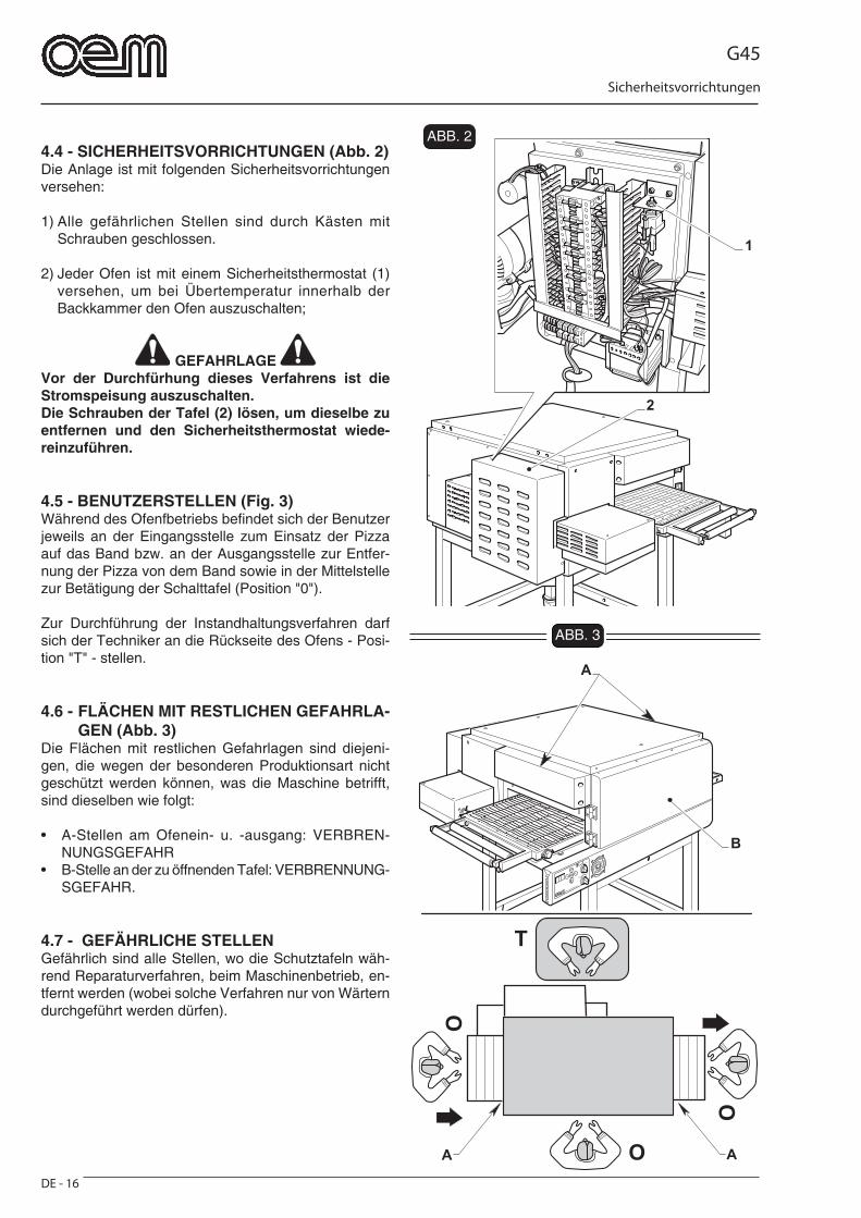
G45
DE - 16
Sicherheitsvorrichtungen
FIG. 3
O
O
O
T
AA
B
A
2
1
FIG. 24.4 - SICHERHEITSVORRICHTUNGEN (Abb. 2)Die Anlage ist mit folgenden Sicherheitsvorrichtungen versehen:
1) Alle gefährlichen Stellen sind durch Kästen mit Schrauben geschlossen.
2) Jeder Ofen ist mit einem Sicherheitsthermostat (1) versehen, um bei Übertemperatur innerhalb der Backkammer den Ofen auszuschalten;
GEFAHRLAGE Vor der Durchfürhung dieses Verfahrens ist die Stromspeisung auszuschalten.Die Schrauben der Tafel (2) lösen, um dieselbe zu entfernen und den Sicherheitsthermostat wiede-reinzuführen.
4.5 - BENUTZERSTELLEN (Fig. 3)Während des Ofenfbetriebs befi ndet sich der Benutzer jeweils an der Eingangsstelle zum Einsatz der Pizza auf das Band bzw. an der Ausgangsstelle zur Entfer-nung der Pizza von dem Band sowie in der Mittelstelle zur Betätigung der Schalttafel (Position "0").
Zur Durchführung der Instandhaltungsverfahren darf sich der Techniker an die Rückseite des Ofens - Posi-tion "T" - stellen.
4.6 - FLÄCHEN MIT RESTLICHEN GEFAHRLA-GEN (Abb. 3)
Die Flächen mit restlichen Gefahrlagen sind diejeni-gen, die wegen der besonderen Produktionsart nicht geschützt werden können, was die Maschine betrifft, sind dieselben wie folgt:
• A-Stellen am Ofenein- u. -ausgang: VERBREN-NUNGSGEFAHR
• B-Stelle an der zu öffnenden Tafel: VERBRENNUNG-SGEFAHR.
4.7 - GEFÄHRLICHE STELLENGefährlich sind alle Stellen, wo die Schutztafeln wäh-rend Reparaturverfahren, beim Maschinenbetrieb, en-tfernt werden (wobei solche Verfahren nur von Wärtern durchgeführt werden dürfen).
ABB. 2
ABB. 3
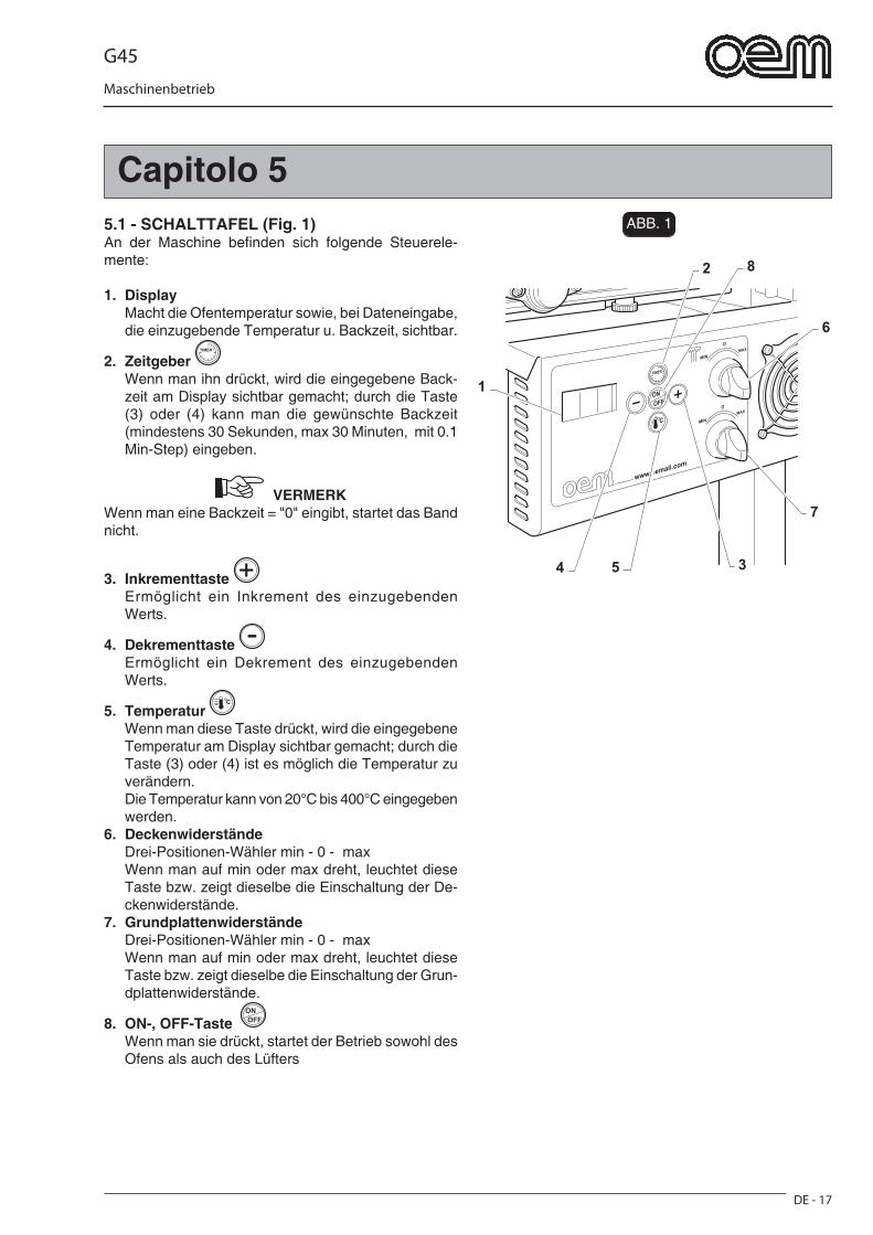
G45
DE - 17
Maschinenbetrieb
Capitolo 5FIG. 1
2
6
7
54 3
8
1
5.1 - SCHALTTAFEL (Fig. 1)An der Maschine befi nden sich folgende Steuerele-mente:
1. Display Macht die Ofentemperatur sowie, bei Dateneingabe,
die einzugebende Temperatur u. Backzeit, sichtbar.
2. Zeitgeber Wenn man ihn drückt, wird die eingegebene Back-
zeit am Display sichtbar gemacht; durch die Taste (3) oder (4) kann man die gewünschte Backzeit (mindestens 30 Sekunden, max 30 Minuten, mit 0.1 Min-Step) eingeben.
VERMERK Wenn man eine Backzeit = "0" eingibt, startet das Band nicht.
3. Inkrementtaste Ermöglicht ein Inkrement des einzugebenden
Werts.
4. Dekrementtaste Ermöglicht ein Dekrement des einzugebenden
Werts.
5. Temperatur Wenn man diese Taste drückt, wird die eingegebene
Temperatur am Display sichtbar gemacht; durch die Taste (3) oder (4) ist es möglich die Temperatur zu verändern.
Die Temperatur kann von 20°C bis 400°C eingegeben werden.
6. Deckenwiderstände Drei-Positionen-Wähler min - 0 - max Wenn man auf min oder max dreht, leuchtet diese
Taste bzw. zeigt dieselbe die Einschaltung der De-ckenwiderstände.
7. Grundplattenwiderstände Drei-Positionen-Wähler min - 0 - max Wenn man auf min oder max dreht, leuchtet diese
Taste bzw. zeigt dieselbe die Einschaltung der Grun-dplattenwiderstände.
8. ON-, OFF-Taste Wenn man sie drückt, startet der Betrieb sowohl des
Ofens als auch des Lüfters
ABB. 1
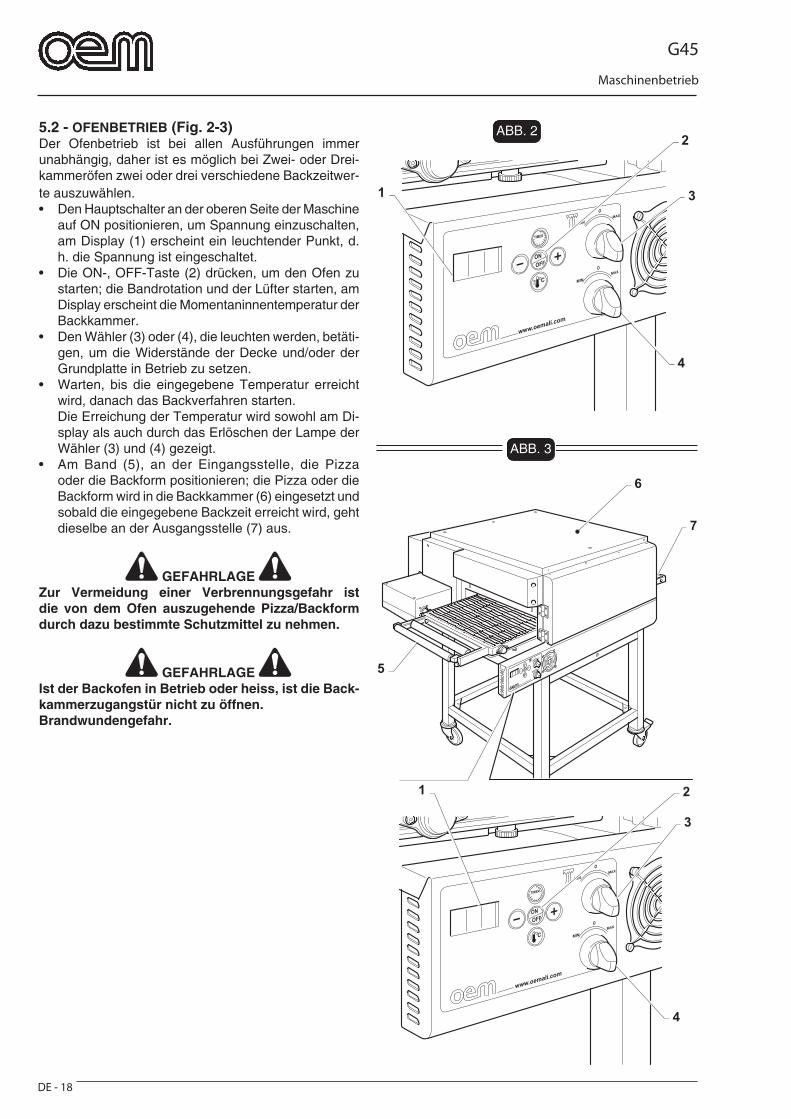
G45
DE - 18
Maschinenbetrieb
FIG. 2
3
4
21
7
6
5
FIG. 3
3
4
2
1
5.2 - OFENBETRIEB (Fig. 2-3)Der Ofenbetrieb ist bei allen Ausführungen immer unabhängig, daher ist es möglich bei Zwei- oder Drei-kammeröfen zwei oder drei verschiedene Backzeitwer-te auszuwählen.• Den Hauptschalter an der oberen Seite der Maschine
auf ON positionieren, um Spannung einzuschalten, am Display (1) erscheint ein leuchtender Punkt, d. h. die Spannung ist eingeschaltet.
• Die ON-, OFF-Taste (2) drücken, um den Ofen zu starten; die Bandrotation und der Lüfter starten, am Display erscheint die Momentaninnentemperatur der Backkammer.
• Den Wähler (3) oder (4), die leuchten werden, betäti-gen, um die Widerstände der Decke und/oder der Grundplatte in Betrieb zu setzen.
• Warten, bis die eingegebene Temperatur erreicht wird, danach das Backverfahren starten.
Die Erreichung der Temperatur wird sowohl am Di-splay als auch durch das Erlöschen der Lampe der Wähler (3) und (4) gezeigt.
• Am Band (5), an der Eingangsstelle, die Pizza oder die Backform positionieren; die Pizza oder die Backform wird in die Backkammer (6) eingesetzt und sobald die eingegebene Backzeit erreicht wird, geht dieselbe an der Ausgangsstelle (7) aus.
GEFAHRLAGE Zur Vermeidung einer Verbrennungsgefahr ist die von dem Ofen auszugehende Pizza/Backform durch dazu bestimmte Schutzmittel zu nehmen.
GEFAHRLAGE Ist der Backofen in Betrieb oder heiss, ist die Back-kammerzugangstür nicht zu öffnen.Brandwundengefahr.
ABB. 2
ABB. 3
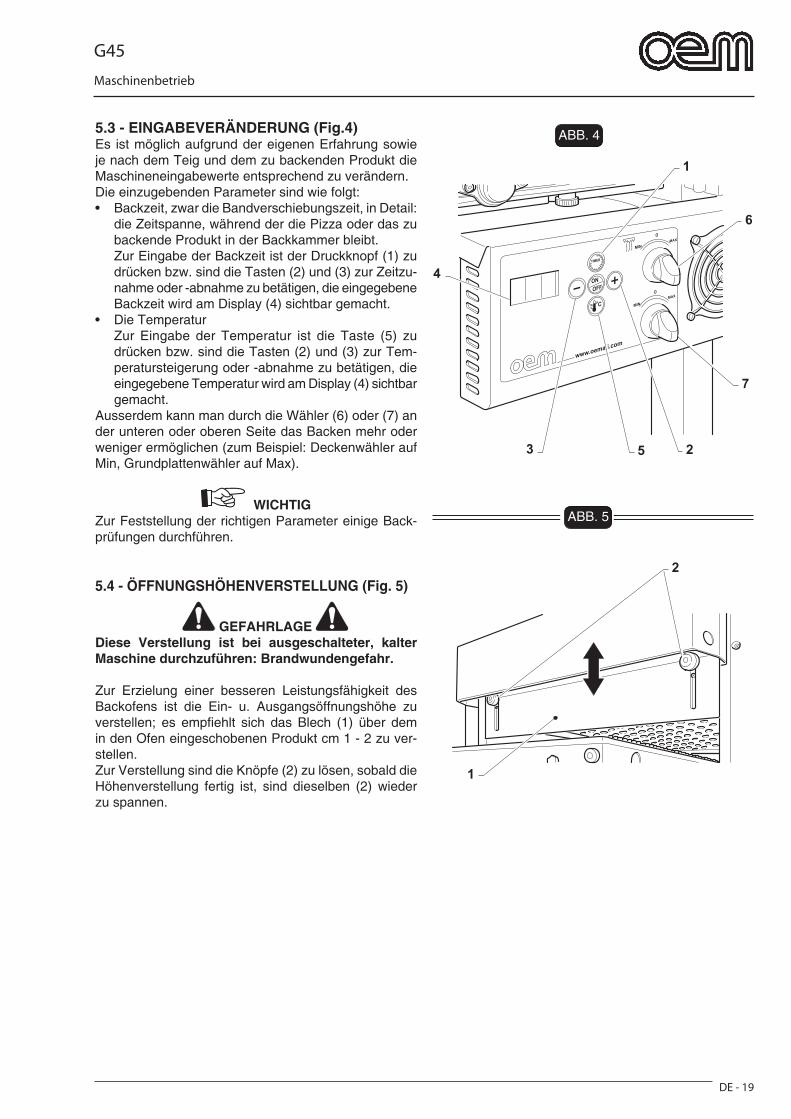
G45
DE - 19
Maschinenbetrieb
FIG. 4
1
6
7
53 2
4
1
2
FIG. 5
5.3 - EINGABEVERÄNDERUNG (Fig.4)Es ist möglich aufgrund der eigenen Erfahrung sowie je nach dem Teig und dem zu backenden Produkt die Maschineneingabewerte entsprechend zu verändern.Die einzugebenden Parameter sind wie folgt:• Backzeit, zwar die Bandverschiebungszeit, in Detail:
die Zeitspanne, während der die Pizza oder das zu backende Produkt in der Backkammer bleibt.
Zur Eingabe der Backzeit ist der Druckknopf (1) zu drücken bzw. sind die Tasten (2) und (3) zur Zeitzu-nahme oder -abnahme zu betätigen, die eingegebene Backzeit wird am Display (4) sichtbar gemacht.
• Die Temperatur Zur Eingabe der Temperatur ist die Taste (5) zu
drücken bzw. sind die Tasten (2) und (3) zur Tem-peratursteigerung oder -abnahme zu betätigen, die eingegebene Temperatur wird am Display (4) sichtbar gemacht.
Ausserdem kann man durch die Wähler (6) oder (7) an der unteren oder oberen Seite das Backen mehr oder weniger ermöglichen (zum Beispiel: Deckenwähler auf Min, Grundplattenwähler auf Max).
WICHTIG Zur Feststellung der richtigen Parameter einige Back-prüfungen durchführen.
5.4 - ÖFFNUNGSHÖHENVERSTELLUNG (Fig. 5)
GEFAHRLAGE Diese Verstellung ist bei ausgeschalteter, kalter Maschine durchzuführen: Brandwundengefahr.
Zur Erzielung einer besseren Leistungsfähigkeit des Backofens ist die Ein- u. Ausgangsöffnungshöhe zu verstellen; es empfi ehlt sich das Blech (1) über dem in den Ofen eingeschobenen Produkt cm 1 - 2 zu ver-stellen.Zur Verstellung sind die Knöpfe (2) zu lösen, sobald die Höhenverstellung fertig ist, sind dieselben (2) wieder zu spannen.
ABB. 4
ABB. 5
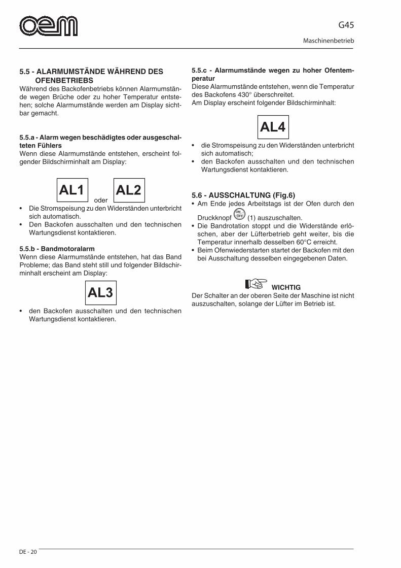
G45
DE - 20
Maschinenbetrieb
5.5 - ALARMUMSTÄNDE WÄHREND DES OFENBETRIEBSWährend des Backofenbetriebs können Alarmumstän-de wegen Brüche oder zu hoher Temperatur entste-hen; solche Alarmumstände werden am Display sicht-bar gemacht.
5.5.a - Alarm wegen beschädigtes oder ausgeschal-teten FühlersWenn diese Alarmumstände entstehen, erscheint fol-gender Bildschirminhalt am Display:
oder • Die Stromspeisung zu den Widerständen unterbricht
sich automatisch.• Den Backofen ausschalten und den technischen
Wartungsdienst kontaktieren.
5.5.b - BandmotoralarmWenn diese Alarmumstände entstehen, hat das Band Probleme; das Band steht still und folgender Bildschir-minhalt erscheint am Display:
AL3
• den Backofen ausschalten und den technischen Wartungsdienst kontaktieren.
5.5.c - Alarmumstände wegen zu hoher Ofentem-peraturDiese Alarmumstände entstehen, wenn die Temperatur des Backofens 430° überschreitet.Am Display erscheint folgender Bildschirminhalt:
AL4
• die Stromspeisung zu den Widerständen unterbricht sich automatisch;
• den Backofen ausschalten und den technischen Wartungsdienst kontaktieren.
5.6 - AUSSCHALTUNG (Fig.6)• Am Ende jedes Arbeitstags ist der Ofen durch den
Druckknopf (1) auszuschalten.• Die Bandrotation stoppt und die Widerstände erlö-
schen, aber der Lüfterbetrieb geht weiter, bis die Temperatur innerhalb desselben 60°C erreicht.
• Beim Ofenwiederstarten startet der Backofen mit den bei Ausschaltung desselben eingegebenen Daten.
WICHTIG Der Schalter an der oberen Seite der Maschine ist nicht auszuschalten, solange der Lüfter im Betrieb ist.
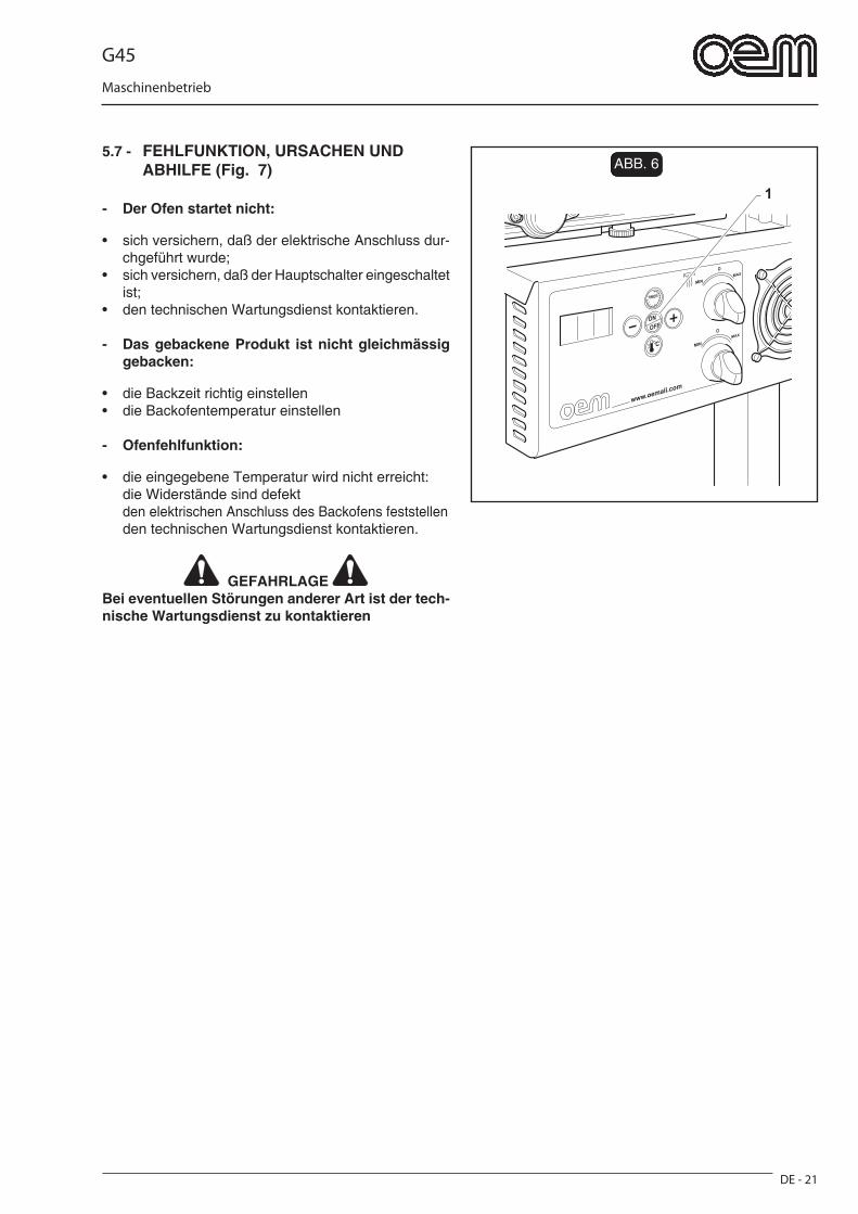
G45
DE - 21
Maschinenbetrieb
FIG. 6
1
5.7 - FEHLFUNKTION, URSACHEN UND ABHILFE (Fig. 7)
- Der Ofen startet nicht:
• sich versichern, daß der elektrische Anschluss dur-chgeführt wurde;
• sich versichern, daß der Hauptschalter eingeschaltet ist;
• den technischen Wartungsdienst kontaktieren.
- Das gebackene Produkt ist nicht gleichmässig gebacken:
• die Backzeit richtig einstellen• die Backofentemperatur einstellen
- Ofenfehlfunktion:
• die eingegebene Temperatur wird nicht erreicht: die Widerstände sind defekt den elektrischen Anschluss des Backofens feststellen den technischen Wartungsdienst kontaktieren.
GEFAHRLAGE Bei eventuellen Störungen anderer Art ist der tech-nische Wartungsdienst zu kontaktieren
ABB. 6
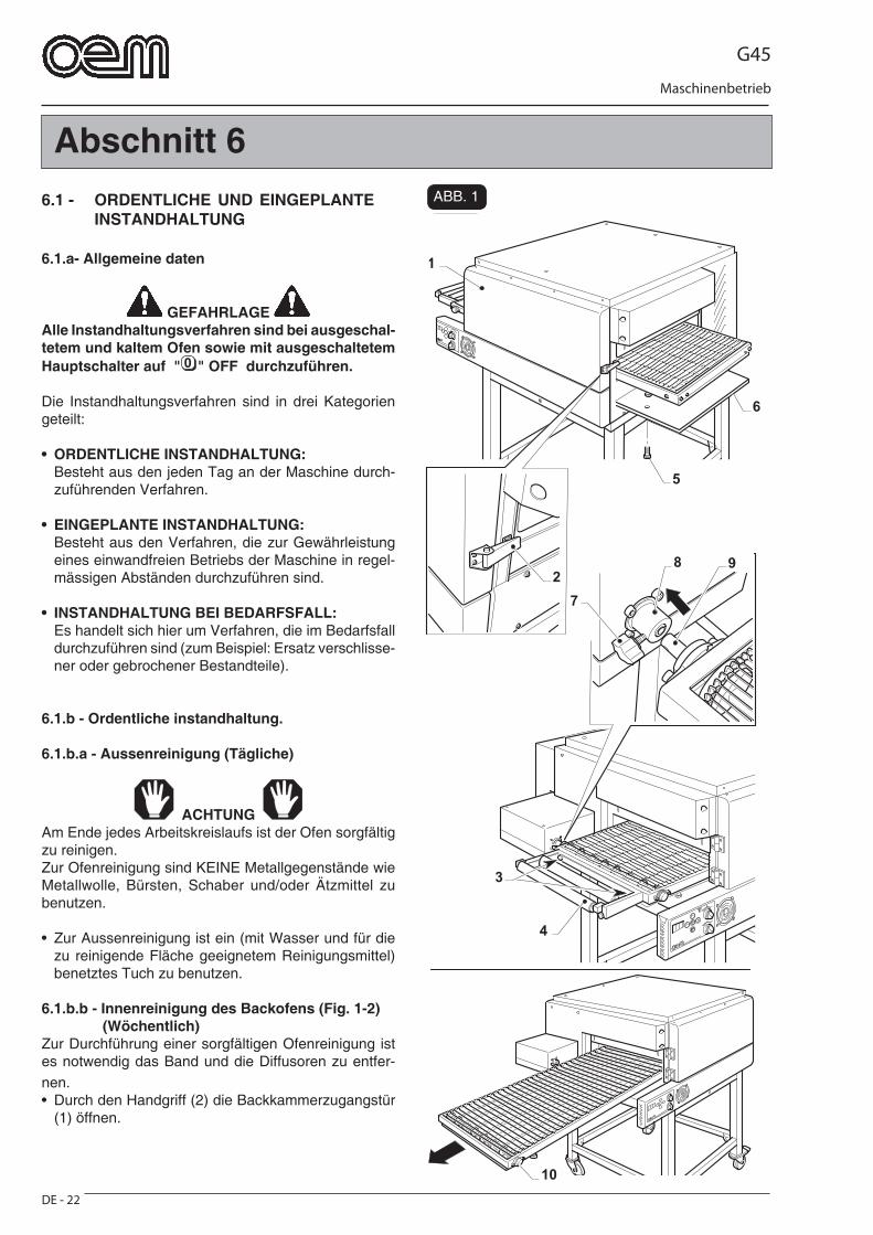
G45
DE - 22
Maschinenbetrieb
1
6
3
4
8 9
7
10
2
5
FIG. 1
Abschnitt 6
6.1 - ORDENTLICHE UND EINGEPLANTE INSTANDHALTUNG
6.1.a- Allgemeine daten
GEFAHRLAGE Alle Instandhaltungsverfahren sind bei ausgeschal-tetem und kaltem Ofen sowie mit ausgeschaltetem Hauptschalter auf " " OFF durchzuführen.
Die Instandhaltungsverfahren sind in drei Kategorien geteilt:
• ORDENTLICHE INSTANDHALTUNG: Besteht aus den jeden Tag an der Maschine durch-
zuführenden Verfahren.
• EINGEPLANTE INSTANDHALTUNG: Besteht aus den Verfahren, die zur Gewährleistung
eines einwandfreien Betriebs der Maschine in regel-mässigen Abständen durchzuführen sind.
• INSTANDHALTUNG BEI BEDARFSFALL: Es handelt sich hier um Verfahren, die im Bedarfsfall
durchzuführen sind (zum Beispiel: Ersatz verschlisse-ner oder gebrochener Bestandteile).
6.1.b - Ordentliche instandhaltung.
6.1.b.a - Aussenreinigung (Tägliche)
ACHTUNG Am Ende jedes Arbeitskreislaufs ist der Ofen sorgfältig zu reinigen.Zur Ofenreinigung sind KEINE Metallgegenstände wie Metallwolle, Bürsten, Schaber und/oder Ätzmittel zu benutzen.
• Zur Aussenreinigung ist ein (mit Wasser und für die zu reinigende Fläche geeignetem Reinigungsmittel) benetztes Tuch zu benutzen.
6.1.b.b - Innenreinigung des Backofens (Fig. 1-2) (Wöchentlich)Zur Durchführung einer sorgfältigen Ofenreinigung ist es notwendig das Band und die Diffusoren zu entfer-nen.• Durch den Handgriff (2) die Backkammerzugangstür
(1) öffnen.
ABB. 1
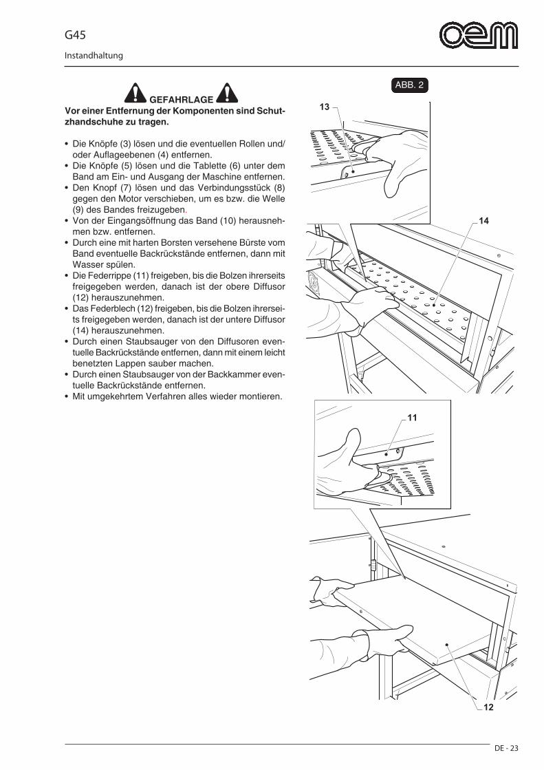
G45
DE - 23
Instandhaltung
FIG. 2
12
11
14
13 GEFAHRLAGE
Vor einer Entfernung der Komponenten sind Schut-zhandschuhe zu tragen.
• Die Knöpfe (3) lösen und die eventuellen Rollen und/oder Aufl ageebenen (4) entfernen.
• Die Knöpfe (5) lösen und die Tablette (6) unter dem Band am Ein- und Ausgang der Maschine entfernen.
• Den Knopf (7) lösen und das Verbindungsstück (8) gegen den Motor verschieben, um es bzw. die Welle (9) des Bandes freizugeben.
• Von der Eingangsöffnung das Band (10) herausneh-men bzw. entfernen.
• Durch eine mit harten Borsten versehene Bürste vom Band eventuelle Backrückstände entfernen, dann mit Wasser spülen.
• Die Federrippe (11) freigeben, bis die Bolzen ihrerseits freigegeben werden, danach ist der obere Diffusor (12) herauszunehmen.
• Das Federblech (12) freigeben, bis die Bolzen ihrersei-ts freigegeben werden, danach ist der untere Diffusor (14) herauszunehmen.
• Durch einen Staubsauger von den Diffusoren even-tuelle Backrückstände entfernen, dann mit einem leicht benetzten Lappen sauber machen.
• Durch einen Staubsauger von der Backkammer even-tuelle Backrückstände entfernen.
• Mit umgekehrtem Verfahren alles wieder montieren.
ABB. 2
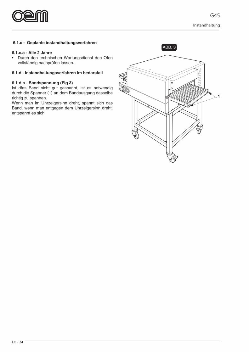
G45
DE - 24
Instandhaltung
FIG. 3
1
6.1.c - Geplante instandhaltungsverfahren
6.1.c.a - Alle 2 Jahre• Durch den technischen Wartungsdienst den Ofen
vollständig nachprüfen lassen.
6.1.d - instandhaltungsverfahren im bedarsfall
6.1.d.a - Bandspannung (Fig.3)Ist dfas Band nicht gut gespannt, ist es notwendig durch die Spanner (1) an dem Bandausgang dasselbe richtig zu spannen.Wenn man im Uhrzeigersinn dreht, spannt sich das Band, wenn man entgegen dem Uhrzeigersinn dreht, entspannt es sich.
ABB. 3
G45
DE - 25
Abmontieren - Abbruch - Entsorgung
Abschnitt 7
7.1 - DEMONTAGE DER MASCHINEIst eine Maschinendemontage durchzuführen und die Maschine dann wieder aufzustellen, dem in dem “Aufstellung”-Abschnitt beschriebenen Verfahren ge-genüber umgekehrt vorgehen.
GEFAHRLAGE Vor der Maschinendemontage die Stromspeisung ausschalten.
Nur gelernte Fachtechniker dürfen dieses Verfahren durchführen.
ACHTUNG Falls es notwendig ist die Maschine anders zu de-montieren oder einige Bestandteile derselben an-ders auszubauen, ist die Firma Hersteller oder ihre Vertretung zu kontaktieren - zu diesem Zweck siehe Adressen auf der dritten Seite dieses Handbuchs.
7.2 - MASCHINENABBRUCH
Hinsichtlich des Umweltschutzes gelten die am Aufstellungsort der Ma-schine gültigen Vorschriften.Wenn die Maschine nicht mehr benut-zt und / oder repariert werden kann, müssen die verschiedenen Maschi-nenkomponenten entsorgt werden.
Elektrische Geräte dürfen nicht in den normalen Hau-shaltsmüll gegeben sondern müssen entsprechend der Bestimmungen zur Abfalltrennung als Industrie-abfall gesondert entsorgt werden.Die elektrischen Geräte sind mit einem besonderen Kennzeichen (durchkreuzter Müllbehälter) versehen. Dieses Kennzeichen zeigt an, daß das Gerät nach dem 13. August 2005 in den Handel gebracht wurde und im Rahmen der Abfalltrennung als Industrieabfall gesondert entsorgt werden muß.Eine unangemessene oder nicht den gesetzlichen Vorschriften entsprechende Entsorgung von elektri-schenGeräten sowie ein unsachgemä§er Einsatz kann aufgrund der Präsenz von gesundheitsschädlichen Substanzen u/o Materialien zu schweren Gesun-dheitsschäden und / oder zu einer schwerwiegenden Umweltbelastung führen. Jede nicht den einschlä-gigen Vorschriften entsprechende Entsorgung von elektrischen Materialien beinhaltet die Verhängung von Geldbußen u/o strafrechtlichen Maßnahmen.
ACHTUNG Was die Entsorgung von Schadstoffen (Schmier-, Lösungsmitteln, Lackierprodukten u.s.w.) betrifft, ist nachfolgender Abschnitt nachzuschlagen.
7.3 - SCHADSTOFFENTSORGUNGZur Entsorgung solcher Stoffe sind die geltenden geset-zlichen Normen in jedem jeweiligen land zu beachten.
ACHTUNG Jedes Vergehen seitens des Kunden vor, während und nach dem Abriss und der Entsorgung der Gerä-teteile hinsichtlich der Auslegung und Anwendung der einschlägig gültigen Bestimmungen wird aus-schließlich von ihm selbst verantwortet.
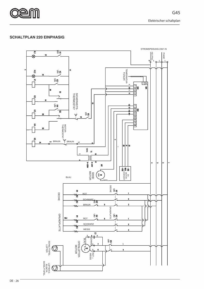
G45
DE - 26
Elektrischer schaltplan
SCHALTPLAN 220 EINPHASIG
STROMSPEISUNG 230/1-N
TE
MP
ER
AT
UR
-F
ÜH
LER
BRAUN BRAUNM
OT
OR
-T
HE
RM
OS
TA
T
M1-
MO
TO
R-
KODIERGERÄT
BA
ND
MO
TO
R
SIC
HE
RH
EIT
S-
TH
ER
MO
ST
AT
DE
CK
EG
RUNDPLATTE
ROT
SCHWARZ
BRAUN
ROT
SCHWARZ
WEISS
BLAU
OF
EN
LÜF
TE
R-
MO
TO
R RO
T +
WE
ISS
SCHWARZ
SC
HA
LTT
AF
EL-
LÜF
TE
R
BLA
U
LÜF
TE
R D
. E
LEK
TR
. S
CH
ALT
TA
FE
L
DE
CK
EG
RU
ND
PLA
TT
E
PH
AS
E
NE
UTR
AL

G45
DE - 27
Elektrischer schaltplan
SCHALTPLAN 230 DREIPHASIG
STROMSPEISUNG 230/3
TE
MP
ER
AT
UR
-F
ÜH
LER
BRAUN BRAUN
MO
TO
R-
TH
ER
MO
ST
AT
BA
ND
MO
TO
R
SIC
HE
RH
EIT
S-
TH
ER
MO
ST
AT
DE
CK
EROT
SCHWARZ
BRAUN
ROT
SCHWARZ
WEISS
OF
EN
LÜF
TE
R-
MO
TO
R RO
T +
WE
ISS
SCHWARZ
BLA
U
LÜF
TE
R D
. E
LEK
TR
. S
CH
ALT
TA
FE
L
DE
CK
E
GRUNDPLATTE
GR
UN
DP
LAT
TE
M1-
MO
TO
R-
KODIERGERÄT
SC
HA
LTT
AF
EL-
LÜF
TE
R
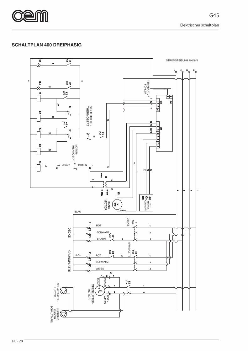
G45
DE - 28
Elektrischer schaltplan
SCHALTPLAN 400 DREIPHASIG
STROMSPEISUNG 400/3-N
TE
MP
ER
AT
UR
-F
ÜH
LER
BRAUN BRAUN
MO
TO
R-
TH
ER
MO
ST
AT
BA
ND
MO
TO
R
SIC
HE
RH
EIT
S-
TH
ER
MO
ST
AT
DE
CK
E
ROT
SCHWARZ
BRAUN
ROT
SCHWARZ
WEISS
BLAU
OF
EN
LÜF
TE
R-
MO
TO
R
RO
T +
WE
ISS
SCHWARZ
SC
HA
LTT
AF
EL-
LÜF
TE
R
BLA
U
LÜF
TE
R D
. E
LEK
TR
. S
CH
ALT
TA
FE
L
DE
CK
E
BLAU
GRUNDPLATTE
GR
UN
DP
LAT
TE
M1-
MO
TO
R-
KODIERGERÄT

G45
DE - 29
Elektrischer schaltplan
LEGENDE
K1 = Hauptfernschalter des DeckenwiderstandsK2 = Economy-Fernschalter des DeckenwiderstandsK3 = Hauptfernschalter des GrundplattenwiderstandsK4 = Economy-Fernschalter des GrundplattenwiderstandsK5 = Ofenlüfter-FernschalterHL1 = Deckenwiderstandssignallampe einHL2 = Grundplattenwiderstandssignallampe einS1 = DeckenwiderstandswählerS2 = GrundplattenwiderstandswählerT1 = Trafo 0-230/0-24V zur Speisung an die Steuerkarte
G45
ES - 1
Normas y advertencias generales
ESPAÑOL
CAPÍTULO ........................................................1Capítulo para el técnico y el operador1.1 ADVERTENCIAS GENERALES ..........................Pág. ES-31.2 NORMAS DE REFERENCIA ...............................Pág. ES-41.3 DESCRIPCIÓN DE LOS SÍMBOLOS ..................Pág. ES-41.4 COMPOSICIÓN DE LA MÁQUINA ......................Pág. ES-41.5 CONEXIONES A CARGO DEL COMPRADOR ...Pág. ES-51.6 OPERACIONES DE EMERGENCIA EN CASO DE INCENDIO ......................................................Pág. ES-51.7 RIESGO DE EXPLOSIÓN ....................................Pág. ES-51.8 NIVEL DE PRESIÓN ACÚSTICA ........................Pág. ES-5
CAPÍTULO ........................................................2Capítulo para el técnico- ESPACIO OCUPADO .................................................Pág. ES-6
2.1 CARACTERÍSTICAS TÉCNICAS .........................Pág. ES-72.2 TRANSPORTE .....................................................Pág. ES-8 2.2.a Envío ...........................................................Pág. ES-8 2.2.b Cómo levantar el embalaje .........................Pág. ES-8 2.2.c Almacenamiento ..........................................Pág. ES-82.3 CONTROLES AL RECIBIR EL PRODUCTO .......Pág. ES-92.4 DESEMBALAJE ...................................................Pág. ES-92.5 IDENTIFICACIÓN DE LOS COMPONENTES .......Pág. ES-102.6 IDENTIFICACIÓN DE LA MÁQUINA .................Pág. ES-10
CAPÍTULO ........................................................3Capítulo para el técnico3.1 CÓMO LEVANTAR LA MÁQUINA .....................Pág. ES-113.2 ENSAMBLAJE DE LOS COMPONENTES ......Pág. ES-113.3 CONEXIÓN ELÉCTRICA ..................................Pág. ES-12 3.3.a Conexión eléctrica del horno .....................Pág. ES-12 3.3.b Conexión equipotencial .............................Pág. ES-133.4 POSICIONAMIENTO DEL HORNO ...................Pág. ES-133.5 PRIMER ENCENDIDO .......................................Pág. ES-133.6 INVERSIÓN DEL SENTIDO DE ROTACIÓN DE LA CINTA .....................................................Pág. ES-143.7 INSTALACIÓN DEL PLANO DE APOYO OPCIONAL .........................................................Pág. ES-143.8 INSTALACIÓN DEL TRANSPORTADOR DE RODILLOS OPCIONAL ......................................Pág. ES-14
CAPÍTULO ........................................................4Capítulo para el técnico y el operador4.1 USO PREVISTO ................................................Pág. ES-154.2 USO INCORRECTO .........................................Pág. ES-154.3 CHAPAS DE SEGURIDAD ................................Pág. ES-154.4 DISPOSITIVOS DE SEGURIDAD ......................Pág. ES-164.5 ZONAS DEL OPERADOR .................................Pág. ES-164.6 ZONAS DE PELIGRO REMANENTE ................Pág. ES-164.7 ZONAS PELIGROSAS .......................................Pág. ES-16
CAPÍTULO ........................................................5Capítulo para el técnico y el operador5.1 PANEL DE MANDOS .........................................Pág. ES-175.2 FUNCIONAMIENTO ...........................................Pág. ES-185.3 MODIFICACIÓN DE LOS PARÁMETROS DE FUNCIONAMIENTO .....................................Pág. ES-195.4 REGULACIÓN DE LA ALTURA DE LA BOCA ..Pág. ES-195.5 ALARMAS DURANTE EL FUNCIONAMIENTO.....Pág. ES-20 5.5.a Alarma sonda de temperatura dañada o desconectada ........................................Pág. ES-20 5.5.b Alarma motor de la cinta ...........................Pág. ES-20 5.5.c Alarma recalentamiento del horno ............Pág. ES-205.6 APAGADO ..........................................................Pág. ES-205.7 FUNCIONAMIENTOS ANÓMALOS, CAUSAS Y SOLUCIONES .................................Pág. ES-21
CAPÍTULO ........................................................6Capítulo para el técnico y el operador6.1 MANTENIMIENTO ORDINARIO Y PROGRAMADO ..............................................Pág. ES-22 6.1.a Generalidades .........................................Pág. ES-22 6.1.b Intervenciones de mantenimiento ordinario ...Pág. ES-22 6.1.b - a Limpieza externa ................................Pág. ES-22 6.1.b - b Limpieza interna del horno ...............Pág. ES-22 6.1.c Intervenciones de mantenimiento programado .............................................Pág. ES-24 6.1.c - a Cada 2 años ......................................Pág. ES-24 6.1.d Intervenciones de mantenimiento segun las necesidades ............................Pág. ES-24 6.1.d - a Tensado de la cinta ............................Pág. ES-24
CAPÍTULO ........................................................7Capítulo para el técnico7.1 DESMONTAJE DE LA MÁQUINA ......................Pág. ES-257.2 DESGUACE DE LA MÁQUINA ..........................Pág. ES-257.3 ELIMINACIÓN DE SUSTANCIAS NOCIVAS .....Pág. ES-25
ESQUEMA ELÉCTRICO 220 MONOFÁSICA ...........Pág. ES-26ESQUEMA ELÉCTRICO 230 TRIFÁSICA ................Pág. ES-27ESQUEMA ELÉCTRICO 400 TRIFÁSICA ................Pág. ES-28
LEYENDA .................................................................Pág. ES-29

G45
ES - 3
Normas y advertencias generales
Capítulo 11.1 - ADVERTENCIAS GENERALES
- Antes de poner en marcha la máquina, el operador tendrá que haber leído con cuidado este manual y haber adquirido un profundo conocimiento de las características técnicas y los mandos.
- Es aconsejable que el operador efectúe un período de adiestramiento sobre el uso de la máquina.
- Antes de efectuar la instalación, controle que el área de-stinada a la máquina sea compatible con el volumen que ocupa y con su peso.
- En caso de instalación o extracción de partes de la máquina, para levantarlas y transportarlas, use sólo herramientas adecuadas a su peso y a sus formas geométricas.
- No permita a personal no autorizado y cualifi cado que ponga en funcionamiento, regule o repare la máquina.
Tome como referencia este manual para efectuar las ope-raciones necesarias.
- Las partes mecánicas y los componentes eléctricos situa-dos dentro de la máquina están protegidos por paneles completamente cerrados por medio de tornillos.
- Antes de efectuar la limpieza y/o mantenimiento de la máqui-na, y antes de quitar cualquier protección, asegúrese de que el interruptor general esté en posición “OFF” (O), para cortar la alimentación eléctrica de la máquina durante la intervención del operador.
- La instalación de alimentación eléctrica del comprador tie-ne que contar con un sistema de desconexión automático colocado antes del interruptor general de la máquina y con una instalación adecuada de tierra que responda a todos los requisitos que establecen las normas para la prevención de accidentes.
- En caso de que haya que intervenir en el interruptor general o en sus cercanías, corte la tensión de la línea en la que está conectado el interruptor general.
- Todos los controles y las operaciones de mantenimiento que requieren la eliminación de las protecciones tienen que ser efectuados bajo la absoluta responsabilidad del usuario.
Por esta razón, se aconseja que estas operaciones sean llevadas a cabo exclusivamente por personal técnico especializado y autorizado.
- Controle que todos los dispositivos de seguridad para prevenir accidentes (barreras, protecciones, cárters, mi-crointerruptores, etc.) no estén dañados y que funcionen perfectamente. En caso contrario ocúpese de arreglarlos.
- No quite los dispositivos de seguridad.
- Para evitar riesgos personales, utilice únicamente herramien-tas adecuadas y conformes a los reglamentos nacionales de seguridad.
- No altere por ningún motivo la instalación eléctrica, neu-mática o cualquier otro mecanismo.
- No deje que la máquina funcione sin estar vigilada.
- Póngase ropa de trabajo aprobada por las normas vigentes a los efectos de prevenir accidentes.
- En caso de operaciones o reparaciones a efectuarse en posiciones que no se alcanzan desde el suelo, utilice esca-leras o herramientas que sean seguras y conformes a los reglamentos nacionales de seguridad.
- En caso de reparaciones cerca o debajo de la máquina, asegúrese de que:
• No haya órganos que puedan arrancar y/o piezas ines-tables que se encuentren posicionados en la máquina o en sus cercanías:
- No utilice las manos en lugar de herramientas para operar en la máquina.
- No utilice las manos u otros objetos para detener partes en movimiento.
- No use cerillas, encendedores o llamas libres en las cer-canías de la máquina.
- PRESTE LA MÁXIMA ATENCIÓN A LAS CHAPAS DE ADVERTENCIA PRESENTES EN LA MÁQUINA CADA VEZ QUE TENGA QUE OPERAR EN LA MISMA O EN SUS CERCANÍAS.
- Es obligación del ususario mantener todas las chapas de señales y advertencias legibles, y si fuera necesario cam-biar su posición para garantizar la completa visibilidad al operador.
- También es obligación del ususario cambiar todas las cha-pas indicadoras y advertencias que por cualquier motivo se hubieran deteriorado o no se leyeran completamente, solicitando las nuevas al Servicio de Recambios.
- Se prohíbe efectuar reparaciones si la máquina está en marcha.
- En caso de un funcionamiento anómalo de la máquina o daños a sus componentes, póngase en contacto con el responsable de mantenimiento, sin efectuar arbitrariamente reparaciones.
- Se prohíbe el uso de la máquina para usos diferentes de los expresamente previstos y documentados.
El uso de la máquina tendrá que efectuarse de manera y según los tiempos y lugares previstos por las normas de buena técnica, de acuerdo a la directiva máquinas CEE 89/392 y respetando las normas referidas a la salud y se-guridad de los trabajadores, indicadas en las leyes vigentes del país de uso o, en ausencia, según la directiva CEE 89/391.
- La empresa fabricante declina toda responsabilidad ante posibles accidentes o daños a personas y cosas que deriven de la inobservancia de las normas de se-guridad, o bien de las instrucciones descritas en este manual.
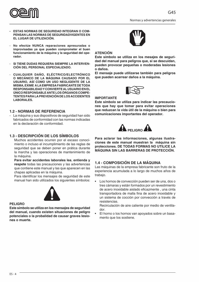
G45
ES - 4
Normas y advertencias generales
- ESTAS NORMAS DE SEGURIDAD INTEGRAN O COM-PENSAN LAS NORMAS DE SEGURIDADVIGENTES EN EL LUGAR DE UTILIZACIÓN.
- No efectúe NUNCA reparaciones apresuradas o improvisadas ya que pueden comprometer el buen funcionamiento de la máquina y la seguridad del ope-rador.
- SI TIENE DUDAS REQUIERA SIEMPRE LA INTERVEN-CIÓN DEL PERSONAL ESPECIALIZADO.
- CUALQUIER DAÑO, ELÉCTRICO/ELECTRÓNICO O MECÁNICO DE LA MÁQUINA CAUSADO POR EL USUARIO, ASÍ COMO UN USO NEGLIGENTE DE LA MISMA, EXIME A LA EMPRESA FABRICANTE DE TODA RESPONSABILIDAD Y CONVIERTE AL USUARIO EN EL ÚNICO RESPONSABLE ANTE LOS ÓRGANOS COMPE-TENTES PARA LA PREVENCIÓN DE LOS ACCIDENTES LABORALES.
1.2 - NORMAS DE REFERENCIA- La máquina y sus dispositivos de seguridad han sido
fabricados de conformidad con las normas indicadas en la declaración de conformidad.
1.3 - DESCRIPCIÓN DE LOS SÍMBOLOSMuchos accidentes ocurren por el escaso conoci-miento o incluso el incumplimiento de las reglas de seguridad que se deben poner en prática durante la marcha y las operaciones de mantenimiento de la máquina. Para evitar accidentes laborales lea, entienda y respete todas las precauciones y las advertencias que contiene este manual y las que aparecen en las chapas aplicadas en la máquina.Para identifi car los mensajes de seguridad de este manual han sido utilizados los siguientes símbolos:
PELIGROEste símbolo se utiliza en los mensajes de seguridad del manual, cuando existen situaciones de peligro potenciales o la probalidad de causar graves lesio-nes o muerte.
ATENCIÓNEste símbolo se utiliza en los mesajes de seguri-dad del manual para peligros que, si se descuidan, pueden provocar pequeñas o moderadas lesiones o daños.El mensaje puede utilizarse también para peligros que pueden acarrear daños a la máquina.
IMPORTANTEEste símbolo se utiliza para indicar las precaucio-nes que hay que tomar para evitar operaciones que reduzcan la vida útil de la máquina o bien para comunicaciones importantes del operador.
PELIGRO
Para aclarar las informaciones, algunas ilustra-ciones de este manual muestran la máquina sin protecciones. DE TODAS FORMAS NO UTILICE LA MÁQUINA SIN LAS BARRERAS DE PROTECCIÓN.
1.4 - COMPOSICIÓN DE LA MÁQUINALas máquinas de la empresa fabricante son fruto de la experiencia acumulada a lo largo de muchos años de trabajo.
• Los hornos de convección pueden ser de una, dos o tres cámaras y están formados por un revestimiento de acero inoxidable aislado efi cazmente , una cinta transportadora de malla fi na de acero inoxidable y un sistema de cocción por convección a través de resistencias.
Recirculación de aire caliente por medio de ventila-dor.
• El horno o los hornos van apoyados sobre un basa-mento que los sostiene.
G45
ES - 5
Normas y advertencias generales
1.5 - CONEXIONES A CARGO DEL COMPRADOR
a) Preparación del lugar en el que se instalará el equipo.
• El comprador debe preparar una superfi cie de apoyo para la máquina como se indica en el capítulo insta-lación.
b) Conexión eléctrica.• La instalación eléctrica de alimentación debe ser
conforme a lo indicado por las normas nacionales vigentes en el lugar de utilización y estar dotada de una efi ciente puesta a tierra.
• Posicione en la línea de alimentación, antes de la máquina, un dispositivo omnipolar de corte.
• Los cables eléctricos de alimentación tienen que dimensionarse en función de la máxima corriente requerida por la máquina de manera que la caída de tensión total, a plena carga, resulte inferior al 2%.
c) Control del neutro• El aparato está dotado de neutro y por lo tando
ha sido colocado un borne idóneo, identifi cado de acuerdo a las normativas específi cas.
1.6 - OPERACIONES DE EMERGENCIA EN CASO DE INCENDIO
a) En caso de incendio corte la tensión que alimenta la máquina desconectando el interruptor general.
b) Apague el incendio utilizando los extintores adecua-dos.
PELIGRO
Se prohíbe terminantemente intentar apagar el in-cendio con agua si la máquina está bajo tensión.
1.7 - RIESGO DE EXPLOSIÓN• La máquina no es adecuada para ser utilizada en
ambientes con riesgos de explosión.
1.8 - NIVEL DE PRESIÓN ACÚSTICALos hornos modelos GHIBLI G45 han sido fabricados con el objetivo de mantener el nivel de presión acústica continuo equivalente ponderado A(dB) por debajo del nivel máximo permitido, es decir 70dB.
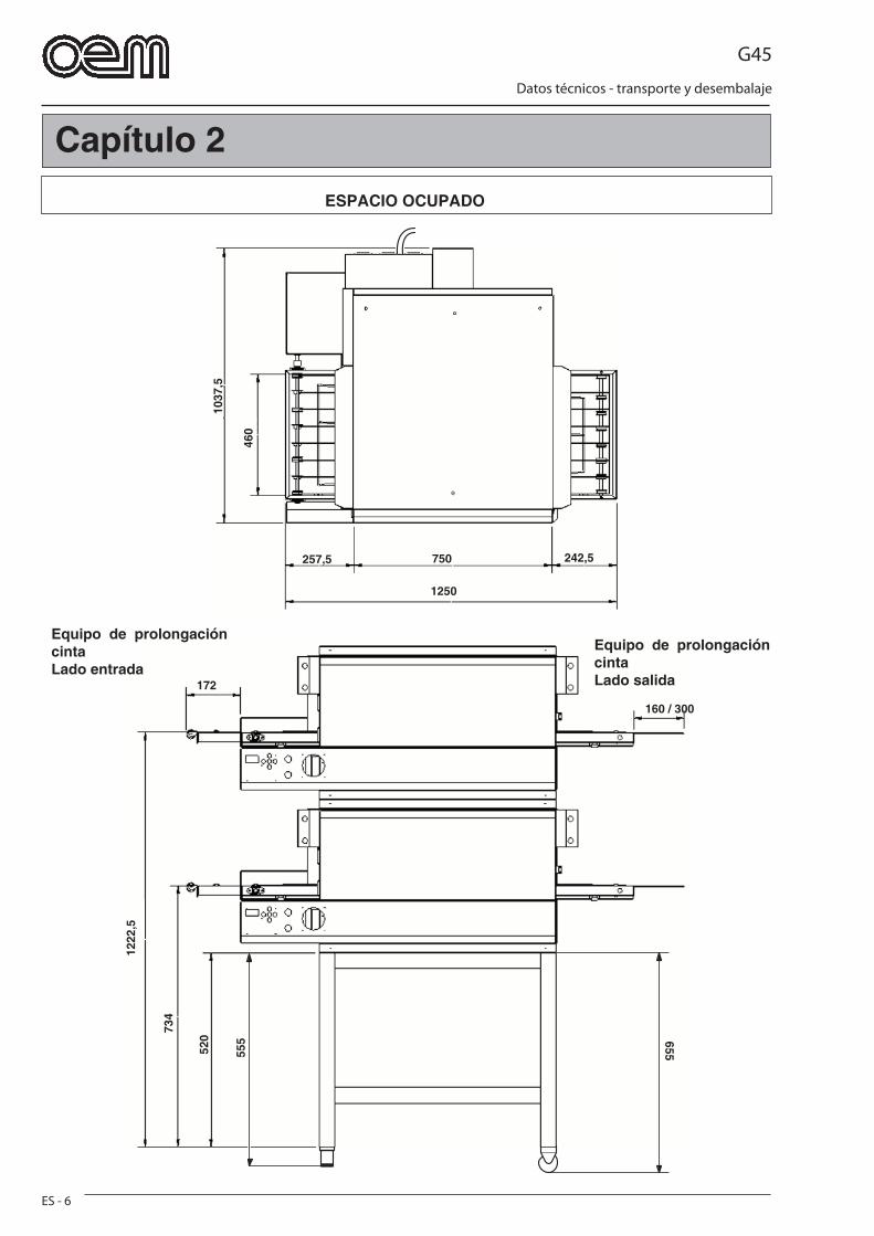
G45
ES - 6
Datos técnicos - transporte y desembalaje
1037
,5
460
750
1250
257,5 242,5
1222
,5
734
520
555 655
160 / 300
172
Capítulo 2
ESPACIO OCUPADO
Equipo de prolongación cintaLado entrada
Equipo de prolongación cintaLado salida
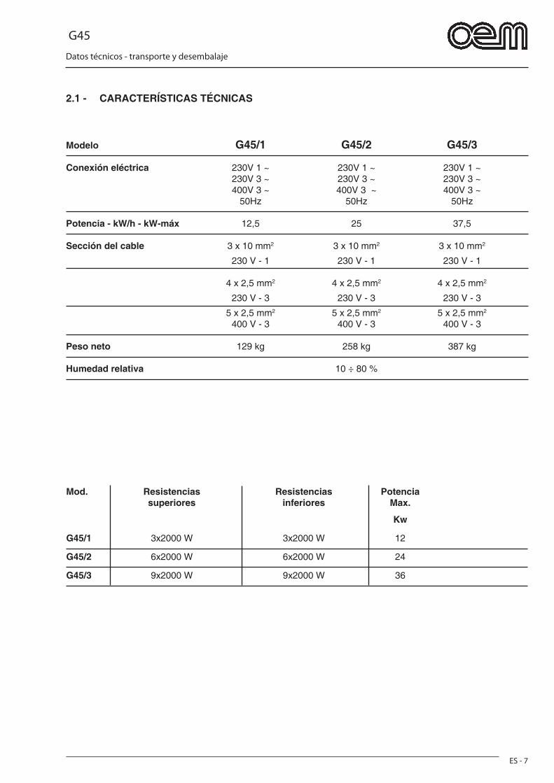
G45
ES - 7
Datos técnicos - transporte y desembalaje
2.1 - CARACTERÍSTICAS TÉCNICAS
Modelo G45/1 G45/2 G45/3
Conexión eléctrica 230V 1 ~ 230V 1 ~ 230V 1 ~ 230V 3 ~ 230V 3 ~ 230V 3 ~ 400V 3 ~ 400V 3 ~ 400V 3 ~ 50Hz 50Hz 50Hz
Potencia - kW/h - kW-máx 12,5 25 37,5
Sección del cable 3 x 10 mm2 3 x 10 mm2 3 x 10 mm2
230 V - 1 230 V - 1 230 V - 1
4 x 2,5 mm2 4 x 2,5 mm2 4 x 2,5 mm2
230 V - 3 230 V - 3 230 V - 3
5 x 2,5 mm2 5 x 2,5 mm2 5 x 2,5 mm2
400 V - 3 400 V - 3 400 V - 3
Peso neto 129 kg 258 kg 387 kg
Humedad relativa 10 ÷ 80 %
Mod. Resistencias Resistencias Potencia superiores inferiores Max.
Kw
G45/1 3x2000 W 3x2000 W 12
G45/2 6x2000 W 6x2000 W 24
G45/3 9x2000 W 9x2000 W 36
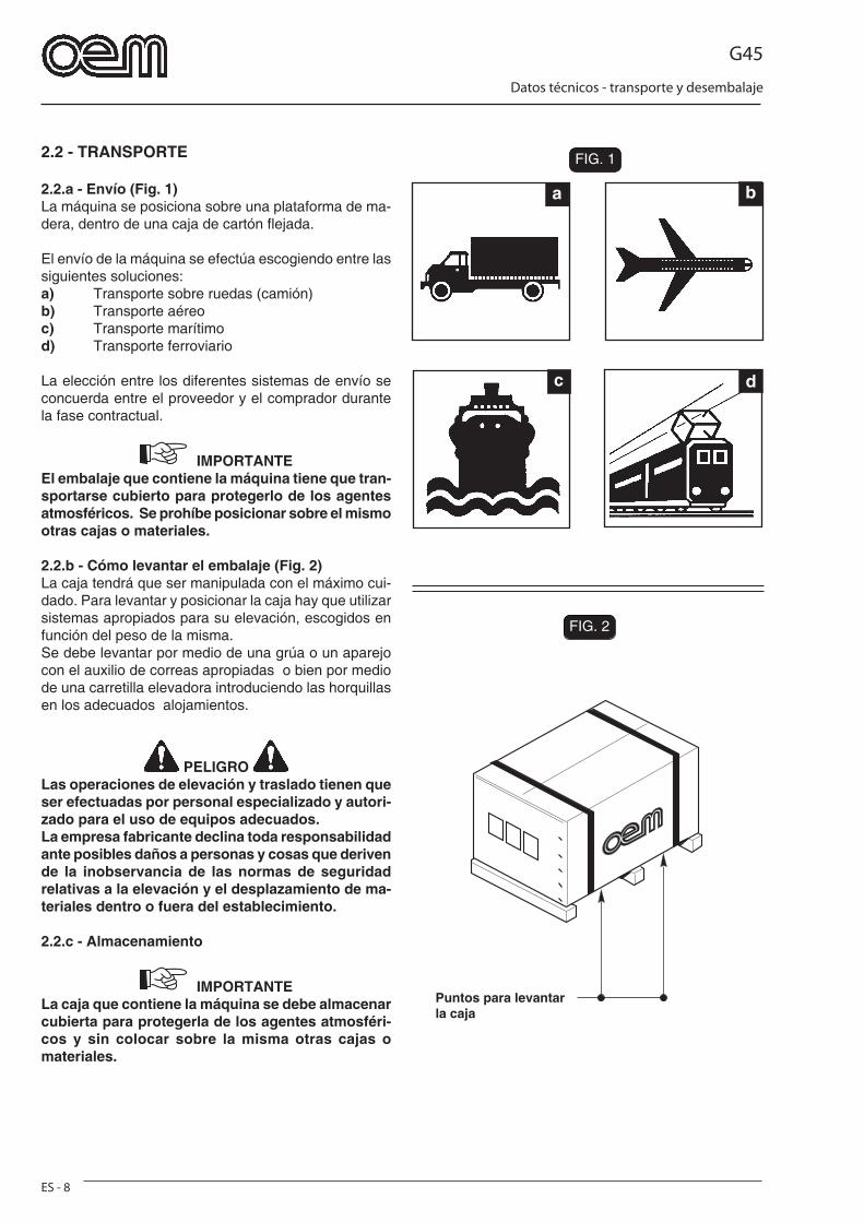
G45
ES - 8
Datos técnicos - transporte y desembalaje
a b
c d
FIG. 2
FIG. 1FIG. 1
FIG. 2
2.2 - TRANSPORTE
2.2.a - Envío (Fig. 1)La máquina se posiciona sobre una plataforma de ma-dera, dentro de una caja de cartón fl ejada.
El envío de la máquina se efectúa escogiendo entre las siguientes soluciones:a) Transporte sobre ruedas (camión)b) Transporte aéreoc) Transporte marítimod) Transporte ferroviario
La elección entre los diferentes sistemas de envío se concuerda entre el proveedor y el comprador durante la fase contractual.
IMPORTANTEEl embalaje que contiene la máquina tiene que tran-sportarse cubierto para protegerlo de los agentes atmosféricos. Se prohíbe posicionar sobre el mismo otras cajas o materiales.
2.2.b - Cómo levantar el embalaje (Fig. 2)La caja tendrá que ser manipulada con el máximo cui-dado. Para levantar y posicionar la caja hay que utilizar sistemas apropiados para su elevación, escogidos en función del peso de la misma.Se debe levantar por medio de una grúa o un aparejo con el auxilio de correas apropiadas o bien por medio de una carretilla elevadora introduciendo las horquillas en los adecuados alojamientos.
PELIGRO Las operaciones de elevación y traslado tienen que ser efectuadas por personal especializado y autori-zado para el uso de equipos adecuados.La empresa fabricante declina toda responsabilidad ante posibles daños a personas y cosas que deriven de la inobservancia de las normas de seguridad relativas a la elevación y el desplazamiento de ma-teriales dentro o fuera del establecimiento.
2.2.c - Almacenamiento
IMPORTANTELa caja que contiene la máquina se debe almacenar cubierta para protegerla de los agentes atmosféri-cos y sin colocar sobre la misma otras cajas o materiales.
Puntos para levantar la caja
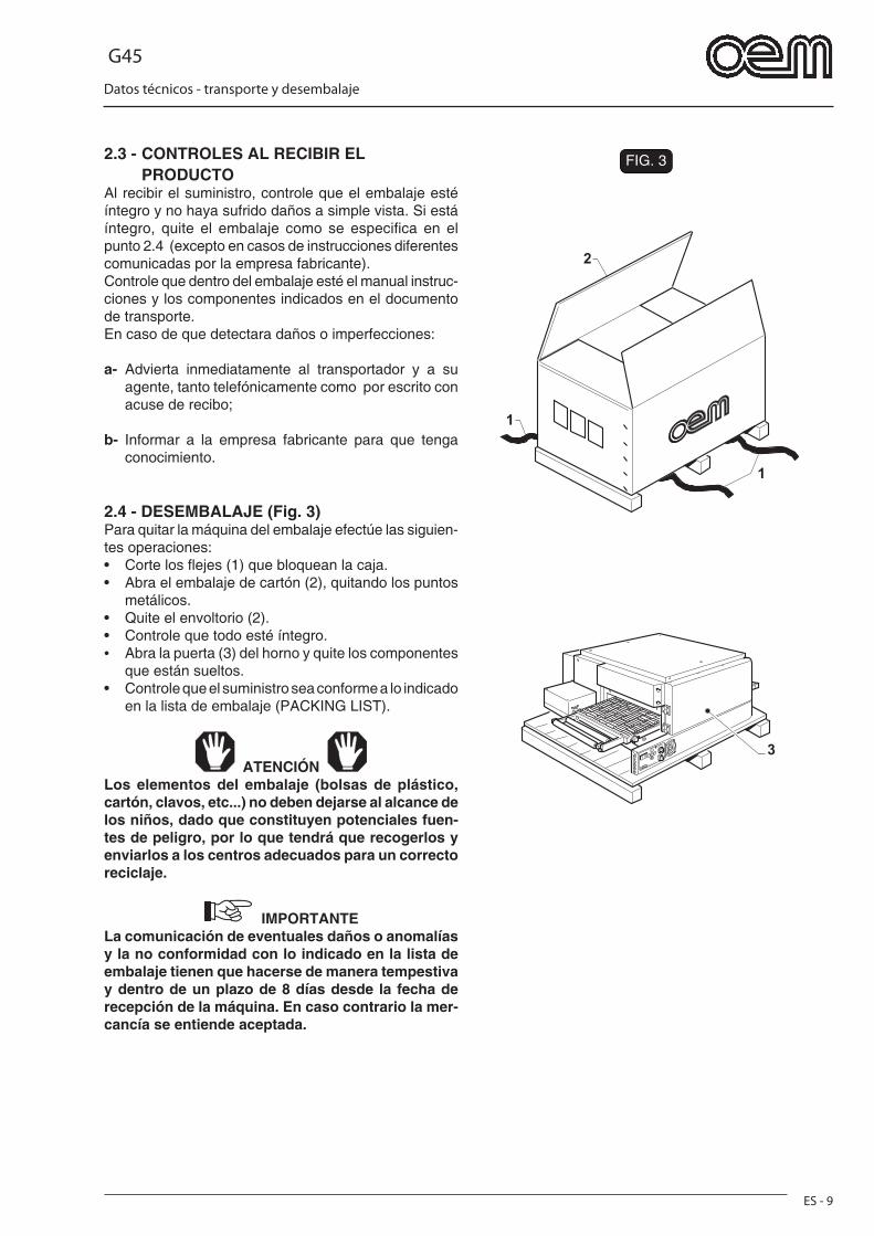
G45
ES - 9
Datos técnicos - transporte y desembalaje
FIG. 3
1
1
2
3
2.3 - CONTROLES AL RECIBIR EL PRODUCTOAl recibir el suministro, controle que el embalaje esté íntegro y no haya sufrido daños a simple vista. Si está íntegro, quite el embalaje como se especifi ca en el punto 2.4 (excepto en casos de instrucciones diferentes comunicadas por la empresa fabricante).Controle que dentro del embalaje esté el manual instruc-ciones y los componentes indicados en el documento de transporte.En caso de que detectara daños o imperfecciones:
a- Advierta inmediatamente al transportador y a su agente, tanto telefónicamente como por escrito con acuse de recibo;
b- Informar a la empresa fabricante para que tenga conocimiento.
2.4 - DESEMBALAJE (Fig. 3)Para quitar la máquina del embalaje efectúe las siguien-tes operaciones:• Corte los fl ejes (1) que bloquean la caja.• Abra el embalaje de cartón (2), quitando los puntos
metálicos.• Quite el envoltorio (2).• Controle que todo esté íntegro. • Abra la puerta (3) del horno y quite los componentes
que están sueltos.• Controle que el suministro sea conforme a lo indicado
en la lista de embalaje (PACKING LIST).
ATENCIÓN Los elementos del embalaje (bolsas de plástico, cartón, clavos, etc...) no deben dejarse al alcance de los niños, dado que constituyen potenciales fuen-tes de peligro, por lo que tendrá que recogerlos y enviarlos a los centros adecuados para un correcto reciclaje.
IMPORTANTELa comunicación de eventuales daños o anomalías y la no conformidad con lo indicado en la lista de embalaje tienen que hacerse de manera tempestiva y dentro de un plazo de 8 días desde la fecha de recepción de la máquina. En caso contrario la mer-cancía se entiende aceptada.
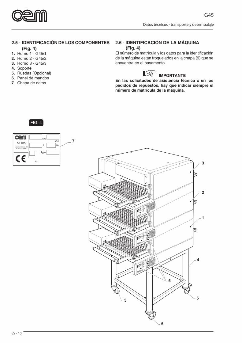
G45
ES - 10
Datos técnicos - transporte y desembalaje
FIG. 4
7
5
55
4
6
1
2
3
2.5 - IDENTIFICACIÓN DE LOS COMPONENTES (Fig. 4)
1. Horno 1 - G45/12. Horno 2 - G45/23. Horno 3 - G45/34. Soporte5. Ruedas (Opcional)6. Panel de mandos7. Chapa de datos
2.6 - IDENTIFICACIÓN DE LA MÁQUINA (Fig. 4)El número de matrícula y los datos para la identifi cación de la máquina están troquelados en la chapa (9) que se encuentra en el basamento.
IMPORTANTE En las solicitudes de asistencia técnica o en los pedidos de repuestos, hay que indicar siempre el número de matrícula de la máquina.
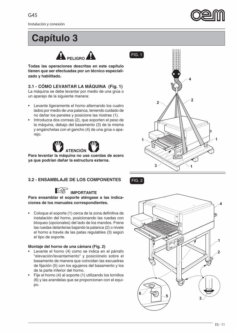
G45
Instalación y conexión
ES - 11
FIG. 2
FIG. 1
4
22
1 1
13
1
3
2
4
65
PELIGRO
Todas las operaciones descritas en este capítulo tienen que ser efectuadas por un técnico especiali-zado y habilitado.
3.1 - CÓMO LEVANTAR LA MÁQUINA (Fig. 1)La máquina se debe levantar por medio de una grúa o un aparejo de la siguiente manera:
• Levante ligeramente el horno alternando los cuatro lados por medio de una palanca, teniendo cuidado de no dañar los paneles y posicione las riostras (1).
• Introduzca dos correas (2), que soporten el peso de la máquina, debajo del basamento (3) de la misma y engánchelas con el gancho (4) de una grúa o apa-rejo.
ATENCIÓN Para levantar la máquina no use cuerdas de acero ya que podrían dañar la estructura externa.
3.2 - ENSAMBLAJE DE LOS COMPONENTES
IMPORTANTEPara ensamblar el soporte aténgase a las indica-ciones de los manuales correspondientes.
• Coloque el soporte (1) cerca de la zona defi nitiva de instalación del horno, posicionando las ruedas con bloqueo (opcionales) del lado de los mandos. Frene las ruedas delanteras bajando la palanca (2) o nivele el horno a través de las patas regulables (3) según el tipo de soporte.
Montaje del horno de una cámara (Fig. 2)• Levante el horno (4) como se indica en el párrafo
"elevación/levantamiento" y posiciónelo sobre el basamento de manera que coincidan las escuadras de fi jación (5) con los agujeros del basamento y los de la parte inferior del horno.
• Fije el horno (4) al soporte (1) utilizando los tornillos (6) y las arandelas que se proporcionan con el equi-po.
Capítulo 3
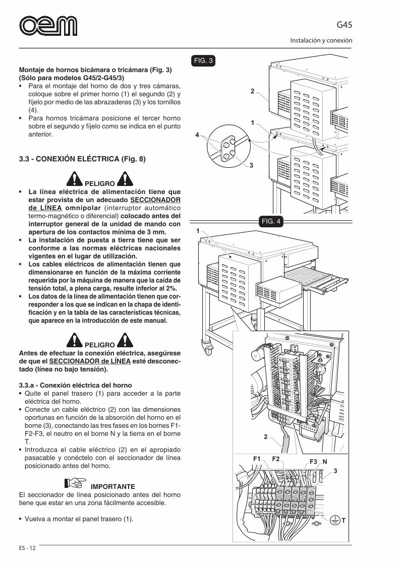
G45
Instalación y conexión
ES - 12
FIG. 3
FIG. 41
2
T
F3 N
3
F2F1
1
2
3
4
Montaje de hornos bicámara o tricámara (Fig. 3)(Sólo para modelos G45/2-G45/3)• Para el montaje del horno de dos y tres cámaras,
coloque sobre el primer horno (1) el segundo (2) y fíjelo por medio de las abrazaderas (3) y los tornillos (4).
• Para hornos tricámara posicione el tercer horno sobre el segundo y fíjelo como se indica en el punto anterior.
3.3 - CONEXIÓN ELÉCTRICA (Fig. 8)
PELIGRO • La línea eléctrica de alimentación tiene que
estar provista de un adecuado SECCIONADOR de LÍNEA omnipolar (interruptor automático termo-magnético o diferencial) colocado antes del interruptor general de la unidad de mando con apertura de los contactos mínima de 3 mm.
• La instalación de puesta a tierra tiene que ser conforme a las normas eléctricas nacionales vigentes en el lugar de utilización.
• Los cables eléctricos de alimentación tienen que dimensionarse en función de la máxima corriente requerida por la máquina de manera que la caída de tensión total, a plena carga, resulte inferior al 2%.
• Los datos de la línea de alimentación tienen que cor-responder a los que se indican en la chapa de identi-fi cación y en la tabla de las características técnicas, que aparece en la introducción de este manual.
PELIGRO Antes de efectuar la conexión eléctrica, asegúrese de que el SECCIONADOR de LÍNEA esté desconec-tado (línea no bajo tensión).
3.3.a - Conexión eléctrica del horno• Quite el panel trasero (1) para acceder a la parte
eléctrica del horno.• Conecte un cable eléctrico (2) con las dimensiones
oportunas en función de la absorción del horno en el borne (3), conectando las tres fases en los bornes F1-F2-F3, el neutro en el borne N y la tierra en el borne T.
• Introduzca el cable eléctrico (2) en el apropiado pasacable y conéctelo con el seccionador de línea posicionado antes del horno.
IMPORTANTEEl seccionador de línea posicionado antes del horno tiene que estar en una zona fácilmente accesible.
• Vuelva a montar el panel trasero (1).
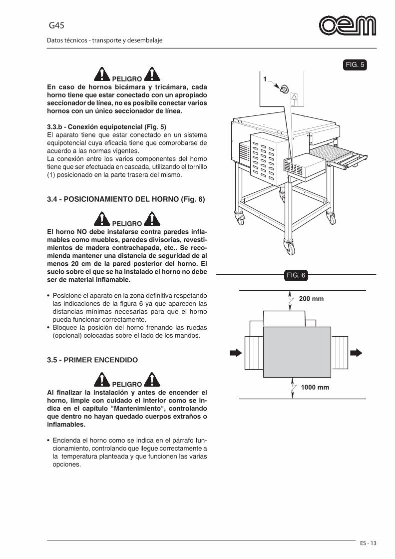
G45
ES - 13
Datos técnicos - transporte y desembalaje
FIG. 5
1
FIG. 6
200 mm
1000 mm
PELIGRO En caso de hornos bicámara y tricámara, cada horno tiene que estar conectado con un apropiado seccionador de línea, no es posibile conectar varios hornos con un único seccionador de línea.
3.3.b - Conexión equipotencial (Fig. 5)El aparato tiene que estar conectado en un sistema equipotencial cuya efi cacia tiene que comprobarse de acuerdo a las normas vigentes.La conexión entre los varios componentes del horno tiene que ser efectuada en cascada, utilizando el tornillo (1) posicionado en la parte trasera del mismo.
3.4 - POSICIONAMIENTO DEL HORNO (Fig. 6)
PELIGRO El horno NO debe instalarse contra paredes infl a-mables como muebles, paredes divisorias, revesti-mientos de madera contrachapada, etc.. Se reco-mienda mantener una distancia de seguridad de al menos 20 cm de la pared posterior del horno. El suelo sobre el que se ha instalado el horno no debe ser de material infl amable.
• Posicione el aparato en la zona defi nitiva respetando las indicaciones de la fi gura 6 ya que aparecen las distancias mínimas necesarias para que el horno pueda funcionar correctamente.
• Bloquee la posición del horno frenando las ruedas (opcional) colocadas sobre el lado de los mandos.
3.5 - PRIMER ENCENDIDO
PELIGRO Al fi nalizar la instalación y antes de encender el horno, limpie con cuidado el interior como se in-dica en el capítulo "Mantenimiento", controlando que dentro no hayan quedado cuerpos extraños o infl amables.
• Encienda el horno como se indica en el párrafo fun-cionamiento, controlando que llegue correctamente a la temperatura planteada y que funcionen las varias opciones.
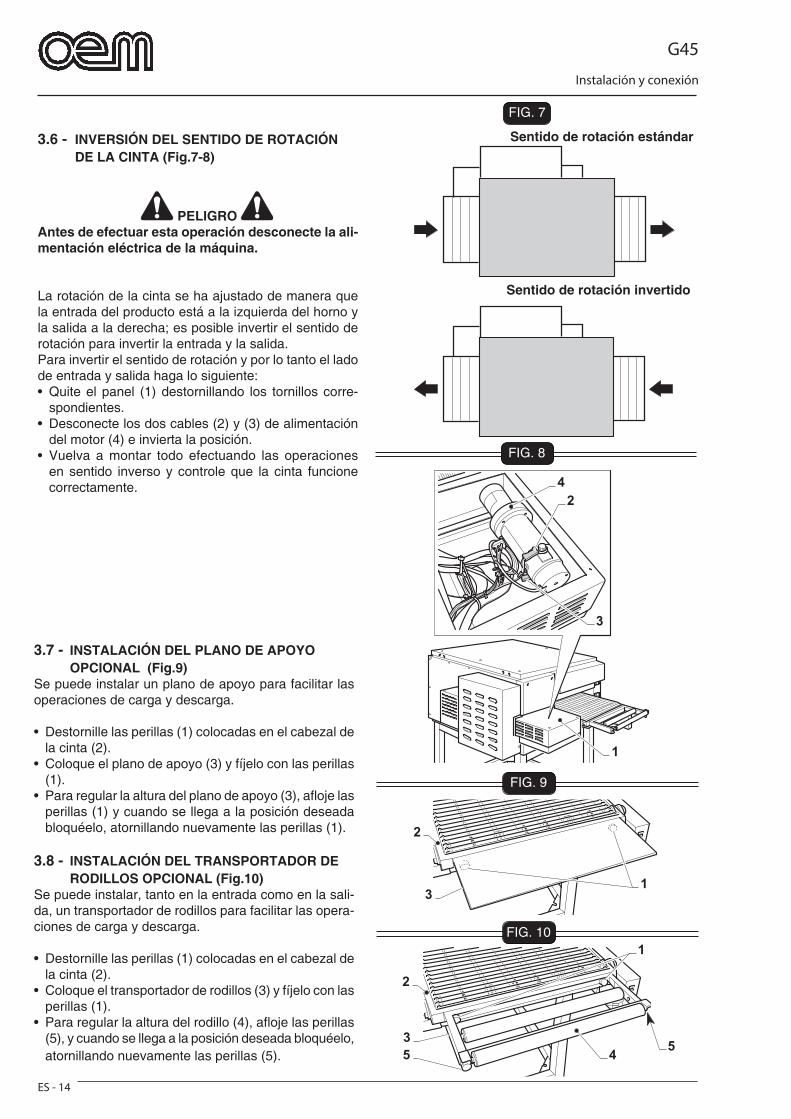
G45
Instalación y conexión
ES - 14
FIG. 7
FIG. 8
FIG. 9
4
2
3
1
45
3
2
1
5
2
13
FIG. 10
3.6 - INVERSIÓN DEL SENTIDO DE ROTACIÓN DE LA CINTA (Fig.7-8)
PELIGRO Antes de efectuar esta operación desconecte la ali-mentación eléctrica de la máquina.
La rotación de la cinta se ha ajustado de manera que la entrada del producto está a la izquierda del horno y la salida a la derecha; es posible invertir el sentido de rotación para invertir la entrada y la salida.Para invertir el sentido de rotación y por lo tanto el lado de entrada y salida haga lo siguiente:• Quite el panel (1) destornillando los tornillos corre-
spondientes.• Desconecte los dos cables (2) y (3) de alimentación
del motor (4) e invierta la posición.• Vuelva a montar todo efectuando las operaciones
en sentido inverso y controle que la cinta funcione correctamente.
Sentido de rotación estándar
Sentido de rotación invertido
3.7 - INSTALACIÓN DEL PLANO DE APOYO OPCIONAL (Fig.9)Se puede instalar un plano de apoyo para facilitar las operaciones de carga y descarga.
• Destornille las perillas (1) colocadas en el cabezal de la cinta (2).
• Coloque el plano de apoyo (3) y fíjelo con las perillas (1).
• Para regular la altura del plano de apoyo (3), afl oje las perillas (1) y cuando se llega a la posición deseada bloquéelo, atornillando nuevamente las perillas (1).
3.8 - INSTALACIÓN DEL TRANSPORTADOR DE RODILLOS OPCIONAL (Fig.10)Se puede instalar, tanto en la entrada como en la sali-da, un transportador de rodillos para facilitar las opera-ciones de carga y descarga.
• Destornille las perillas (1) colocadas en el cabezal de la cinta (2).
• Coloque el transportador de rodillos (3) y fíjelo con las perillas (1).
• Para regular la altura del rodillo (4), afl oje las perillas (5), y cuando se llega a la posición deseada bloquéelo, atornillando nuevamente las perillas (5).
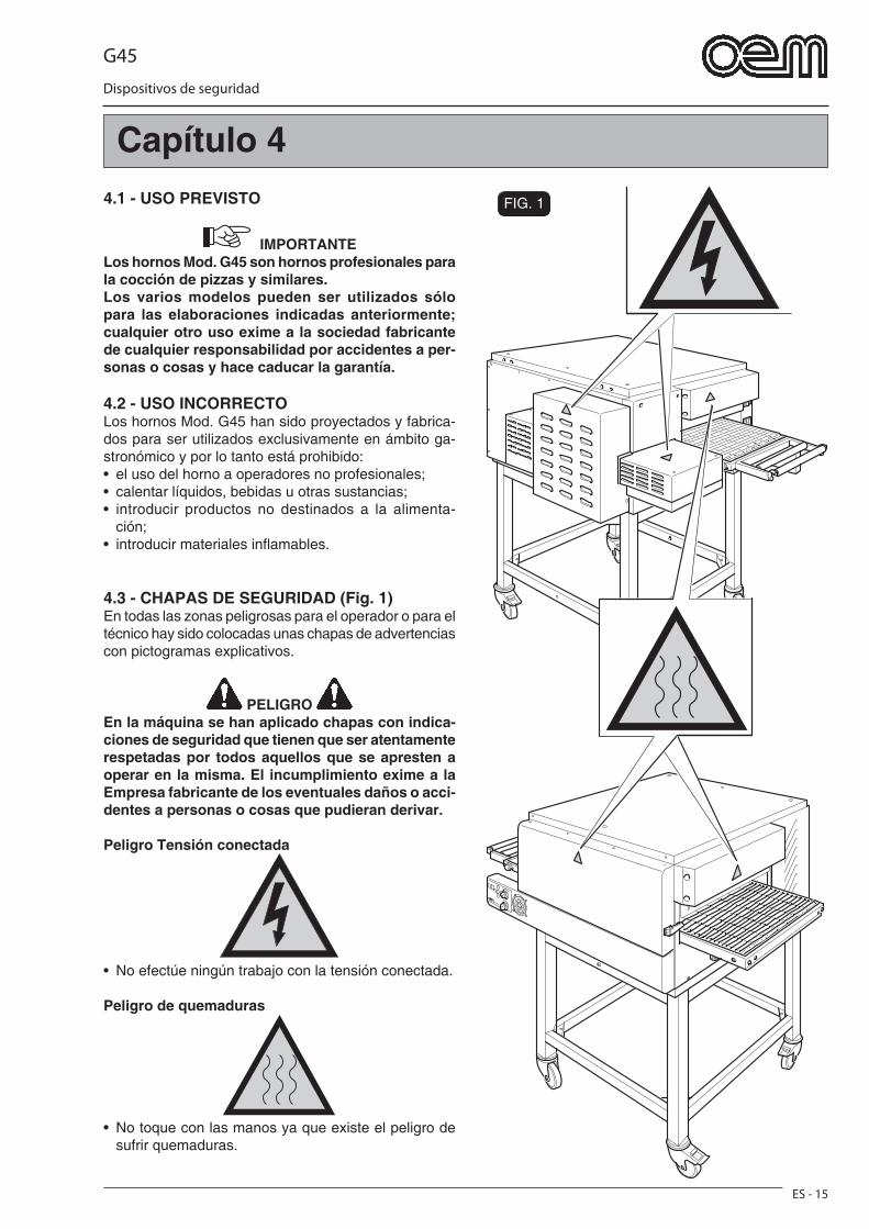
G45
Dispositivos de seguridad
ES - 15
FIG. 14.1 - USO PREVISTO
IMPORTANTE Los hornos Mod. G45 son hornos profesionales para la cocción de pizzas y similares.Los varios modelos pueden ser utilizados sólo para las elaboraciones indicadas anteriormente; cualquier otro uso exime a la sociedad fabricante de cualquier responsabilidad por accidentes a per-sonas o cosas y hace caducar la garantía.
4.2 - USO INCORRECTOLos hornos Mod. G45 han sido proyectados y fabrica-dos para ser utilizados exclusivamente en ámbito ga-stronómico y por lo tanto está prohibido:• el uso del horno a operadores no profesionales;• calentar líquidos, bebidas u otras sustancias;• introducir productos no destinados a la alimenta-
ción;• introducir materiales infl amables.
4.3 - CHAPAS DE SEGURIDAD (Fig. 1)En todas las zonas peligrosas para el operador o para el técnico hay sido colocadas unas chapas de advertencias con pictogramas explicativos.
PELIGRO En la máquina se han aplicado chapas con indica-ciones de seguridad que tienen que ser atentamente respetadas por todos aquellos que se apresten a operar en la misma. El incumplimiento exime a la Empresa fabricante de los eventuales daños o acci-dentes a personas o cosas que pudieran derivar.
Peligro Tensión conectada
• No efectúe ningún trabajo con la tensión conectada.
Peligro de quemaduras
• No toque con las manos ya que existe el peligro de sufrir quemaduras.
Capítulo 4
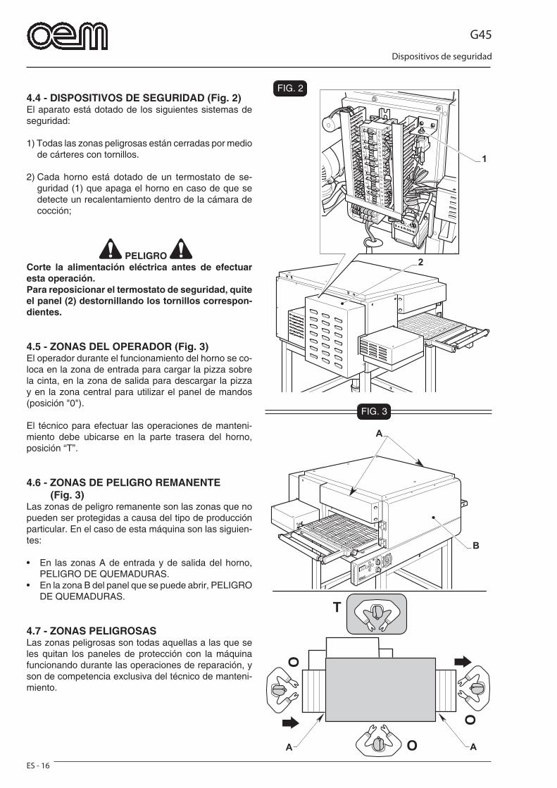
G45
Dispositivos de seguridad
ES - 16
FIG. 3
O
O
O
T
AA
B
A
2
1
FIG. 24.4 - DISPOSITIVOS DE SEGURIDAD (Fig. 2)El aparato está dotado de los siguientes sistemas de seguridad:
1) Todas las zonas peligrosas están cerradas por medio de cárteres con tornillos.
2) Cada horno está dotado de un termostato de se-guridad (1) que apaga el horno en caso de que se detecte un recalentamiento dentro de la cámara de cocción;
PELIGRO Corte la alimentación eléctrica antes de efectuar esta operación.Para reposicionar el termostato de seguridad, quite el panel (2) destornillando los tornillos correspon-dientes.
4.5 - ZONAS DEL OPERADOR (Fig. 3)El operador durante el funcionamiento del horno se co-loca en la zona de entrada para cargar la pizza sobre la cinta, en la zona de salida para descargar la pizza y en la zona central para utilizar el panel de mandos (posición "0").
El técnico para efectuar las operaciones de manteni-miento debe ubicarse en la parte trasera del horno, posición “T”.
4.6 - ZONAS DE PELIGRO REMANENTE (Fig. 3)Las zonas de peligro remanente son las zonas que no pueden ser protegidas a causa del tipo de producción particular. En el caso de esta máquina son las siguien-tes:
• En las zonas A de entrada y de salida del horno, PELIGRO DE QUEMADURAS.
• En la zona B del panel que se puede abrir, PELIGRO DE QUEMADURAS.
4.7 - ZONAS PELIGROSASLas zonas peligrosas son todas aquellas a las que se les quitan los paneles de protección con la máquina funcionando durante las operaciones de reparación, y son de competencia exclusiva del técnico de manteni-miento.
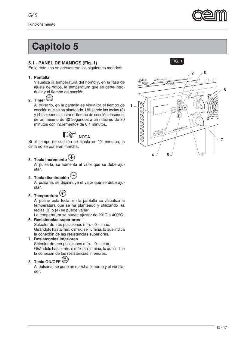
G45
Funcionamiento
ES - 17
Capitolo 5FIG. 1
2
6
7
54 3
8
1
5.1 - PANEL DE MANDOS (Fig. 1)En la máquina se encuentran los siguientes mandos:
1. Pantalla Visualiza la temperatura del horno y, en la fase de
ajuste de datos, la temperatura que se debe intro-ducir y el tiempo de cocción.
2. Timer Al pulsarlo, en la pantalla se visualiza el tiempo de
cocción que se ha planteado. Utilizando las teclas (3) y (4) se puede ajustar el tiempo de cocción deseado, de un mínimo de 30 segundos a un máximo de 30 minutos con incrementos de 0.1 minutos.
NOTA Si el tiempo de cocción se ajusta en "0" minutos, la cinta no se pone en marcha.
3. Tecla incremento Al pulsarla, se aumenta el valor que se debe aju-
star.
4. Tecla disminución Al pulsarla, se disminuye el valor que se debe aju-
star.
5. Temperatura Al pulsar esta tecla, en la pantalla se visualiza la
temperatura que se ha planteado y utilizando las teclas (3) ó (4) se puede variar.
La temperatura se puede ajustar de 20°C a 400°C.6. Resistencias superiores Selector de tres posiciones mín. - 0 - máx. Girándolo hasta mín. o máx. se ilumina, lo que indica
la conexión de las resistencias superiores. 7. Resistencias inferiores Selector de tres posiciones mín. - 0 - máx. Girándolo hasta mín. o máx. se ilumina, lo que indica
la conexión de las resistencias inferiores.
8. Tecla ON/OFF Al pulsarla, se pone en marcha el horno y el ventila-
dor.
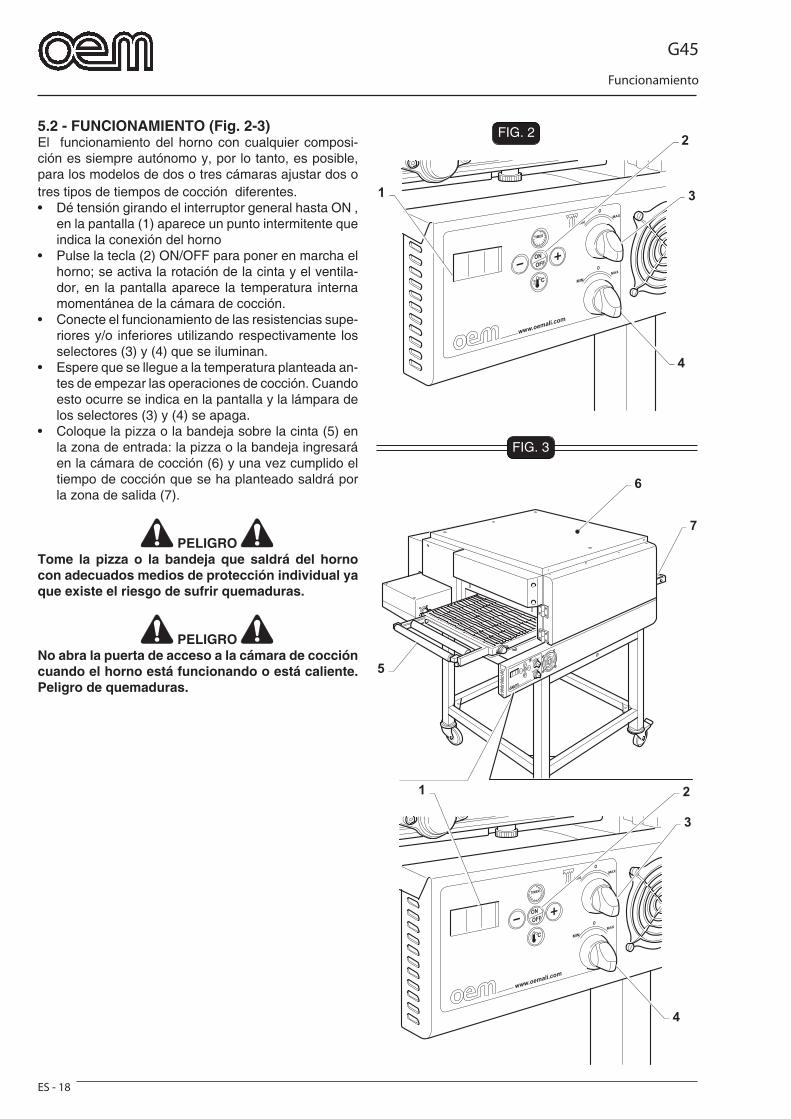
G45
Funcionamiento
ES - 18
FIG. 2
3
4
21
7
6
5
FIG. 3
3
4
2
1
5.2 - FUNCIONAMIENTO (Fig. 2-3)El funcionamiento del horno con cualquier composi-ción es siempre autónomo y, por lo tanto, es posible, para los modelos de dos o tres cámaras ajustar dos o tres tipos de tiempos de cocción diferentes.• Dé tensión girando el interruptor general hasta ON ,
en la pantalla (1) aparece un punto intermitente que indica la conexión del horno
• Pulse la tecla (2) ON/OFF para poner en marcha el horno; se activa la rotación de la cinta y el ventila-dor, en la pantalla aparece la temperatura interna momentánea de la cámara de cocción.
• Conecte el funcionamiento de las resistencias supe-riores y/o inferiores utilizando respectivamente los selectores (3) y (4) que se iluminan.
• Espere que se llegue a la temperatura planteada an-tes de empezar las operaciones de cocción. Cuando esto ocurre se indica en la pantalla y la lámpara de los selectores (3) y (4) se apaga.
• Coloque la pizza o la bandeja sobre la cinta (5) en la zona de entrada: la pizza o la bandeja ingresará en la cámara de cocción (6) y una vez cumplido el tiempo de cocción que se ha planteado saldrá por la zona de salida (7).
PELIGRO Tome la pizza o la bandeja que saldrá del horno con adecuados medios de protección individual ya que existe el riesgo de sufrir quemaduras.
PELIGRO No abra la puerta de acceso a la cámara de cocción cuando el horno está funcionando o está caliente. Peligro de quemaduras.
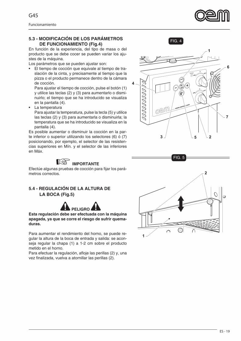
G45
Funcionamiento
ES - 19
FIG. 4
1
6
7
53 2
4
1
2
FIG. 5
5.3 - MODIFICACIÓN DE LOS PARÁMETROS DE FUNCIONAMIENTO (Fig.4)En función de la experiencia, del tipo de masa o del producto que se debe cocer se pueden variar los aju-stes de la máquina.Los parámetros que se pueden ajustar son:• El tiempo de cocción que equivale al tiempo de tra-
slación de la cinta, y precisamente al tiempo que la pizza o el producto permanece dentro de la cámara de cocción.
Para ajustar el tiempo de cocción, pulse el botón (1) y utilice las teclas (2) y (3) para aumentarlo o dismi-nuirlo; el tiempo que se ha introducido se visualiza en la pantalla (4).
• La temperatura Para ajustar la temperatura, pulse la tecla (5) y utilice
las teclas (2) y (3) para aumentarla o disminuirla; la temperatura que se ha introducido se visualiza en la pantalla (4).
Es posible aumentar o disminuir la cocción en la par-te inferior o superior utilizando los selectores (6) ó (7) posicionando, por ejemplo, el selector de las resisten-cias superiores en Mín. y el selector de las inferiores en Máx.
IMPORTANTE Efectúe algunas pruebas de cocción para fi jar los pará-metros correctos.
5.4 - REGULACIÓN DE LA ALTURA DE LA BOCA (Fig.5)
PELIGRO Esta regulación debe ser efectuada con la máquina apagada, ya que se corre el riesgo de sufrir quema-duras.
Para aumentar el rendimiento del horno, se puede re-gular la altura de la boca de entrada y salida: se acon-seja regular la chapa (1) a 1-2 cm sobre el producto metido en el horno.Para efectuar la regulación, afl oje las perillas (2) y, una vez fi nalizada, vuelva a atornillar las perillas (2).
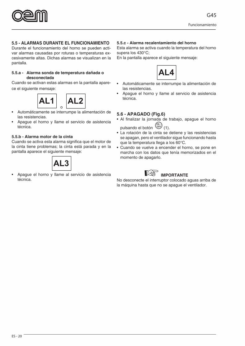
G45
Funcionamiento
ES - 20
5.5 - ALARMAS DURANTE EL FUNCIONAMIENTODurante el funcionamiento del horno se pueden acti-var alarmas causadas por roturas o temperaturas ex-cesivamente altas. Dichas alarmas se visualizan en la pantalla. 5.5.a - Alarma sonda de temperatura dañada o desconectadaCuando se activan estas alarmas en la pantalla apare-ce el siguiente mensaje:
o • Automáticamente se interrumpe la alimentación de
las resistencias.• Apague el horno y llame el servicio de asistencia
técnica.
5.5.b - Alarma motor de la cintaCuando se activa esta alarma signifi ca que el motor de la cinta tiene problemas; la cinta está parada y en la pantalla aparece el siguiente mensaje:
AL3
• Apague el horno y llame al servicio de asistencia técnica.
5.5.c - Alarma recalentamiento del hornoEsta alarma se activa cuando la temperatura del horno supera los 430°C;En la pantalla aparece el siguiente mensaje:
AL4
• Automáticamente se interrumpe la alimentación de las resistencias.
• Apague el horno y llame al servicio de asistencia técnica.
5.6 - APAGADO (Fig.6)• Al fi nalizar la jornada de trabajo, apague el horno
pulsando el botón (1).• La rotación de la cinta se detiene y las resistencias
se apagan, pero el ventilador sigue funcionando hasta que la temperatura llega a los 60°C.
• Cuando se vuelve a encender el horno, se pone en marcha con los datos que tenía memorizados en el momento de apagarlo.
IMPORTANTE No desconecte el interruptor colocado aguas arriba de la máquina hasta que no se apague el ventilador.
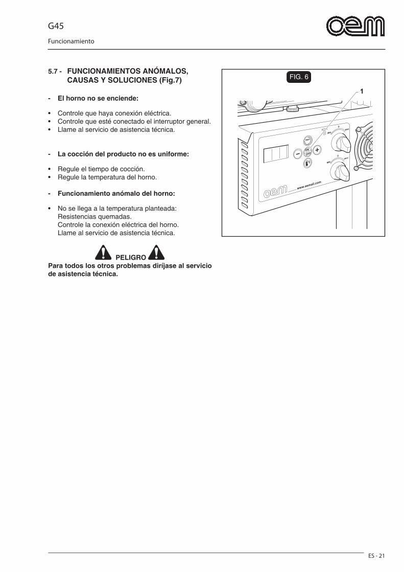
G45
Funcionamiento
ES - 21
FIG. 6
1
5.7 - FUNCIONAMIENTOS ANÓMALOS, CAUSAS Y SOLUCIONES (Fig.7)
- El horno no se enciende:
• Controle que haya conexión eléctrica. • Controle que esté conectado el interruptor general.• Llame al servicio de asistencia técnica.
- La cocción del producto no es uniforme:
• Regule el tiempo de cocción. • Regule la temperatura del horno.
- Funcionamiento anómalo del horno:
• No se llega a la temperatura planteada: Resistencias quemadas. Controle la conexión eléctrica del horno. Llame al servicio de asistencia técnica.
PELIGRO Para todos los otros problemas diríjase al servicio de asistencia técnica.
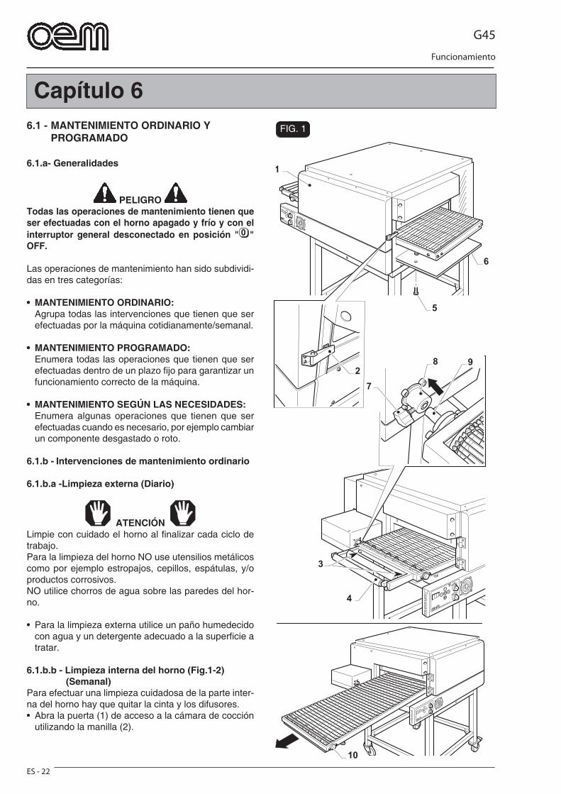
G45
Funcionamiento
ES - 22
1
6
3
4
8 9
7
10
2
5
FIG. 1
Capítulo 66.1 - MANTENIMIENTO ORDINARIO Y PROGRAMADO
6.1.a- Generalidades
PELIGRO Todas las operaciones de mantenimiento tienen que ser efectuadas con el horno apagado y frío y con el interruptor general desconectado en posición " " OFF.
Las operaciones de mantenimiento han sido subdividi-das en tres categorías:
• MANTENIMIENTO ORDINARIO: Agrupa todas las intervenciones que tienen que ser
efectuadas por la máquina cotidianamente/semanal.
• MANTENIMIENTO PROGRAMADO: Enumera todas las operaciones que tienen que ser
efectuadas dentro de un plazo fi jo para garantizar un funcionamiento correcto de la máquina.
• MANTENIMIENTO SEGÚN LAS NECESIDADES: Enumera algunas operaciones que tienen que ser
efectuadas cuando es necesario, por ejemplo cambiar un componente desgastado o roto.
6.1.b - Intervenciones de mantenimiento ordinario
6.1.b.a -Limpieza externa (Diario)
ATENCIÓN Limpie con cuidado el horno al fi nalizar cada ciclo de trabajo.Para la limpieza del horno NO use utensilios metálicos como por ejemplo estropajos, cepillos, espátulas, y/o productos corrosivos.NO utilice chorros de agua sobre las paredes del hor-no.
• Para la limpieza externa utilice un paño humedecido con agua y un detergente adecuado a la superfi cie a tratar.
6.1.b.b - Limpieza interna del horno (Fig.1-2) (Semanal)Para efectuar una limpieza cuidadosa de la parte inter-na del horno hay que quitar la cinta y los difusores. • Abra la puerta (1) de acceso a la cámara de cocción
utilizando la manilla (2).
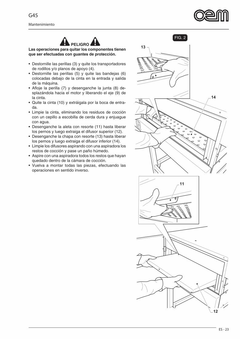
G45
Mantenimiento
ES - 23
FIG. 2
12
11
14
13 PELIGRO
Las operaciones para quitar los componentes tienen que ser efectuadas con guantes de protección.
• Destornille las perillas (3) y quite los transportadores de rodillos y/o planos de apoyo (4).
• Destornille las perillas (5) y quite las bandejas (6) colocadas debajo de la cinta en la entrada y salida de la máquina.
• Afl oje la perilla (7) y desenganche la junta (8) de-splazándola hacia el motor y liberando el eje (9) de la cinta.
• Quite la cinta (10) y extráigala por la boca de entra-da.
• Limpie la cinta, eliminando los residuos de cocción con un cepillo a escobilla de cerda dura y enjuague con agua.
• Desenganche la aleta con resorte (11) hasta liberar los pernos y luego extraiga el difusor superior (12).
• Desenganche la chapa con resorte (13) hasta liberar los pernos y luego extraiga el difusor inferior (14).
• Limpie los difusores aspirando con una aspiradora los restos de cocción y pase un paño húmedo.
• Aspire con una aspiradora todos los restos que hayan quedado dentro de la cámara de cocción.
• Vuelva a montar todas las piezas, efectuando las operaciones en sentido inverso.
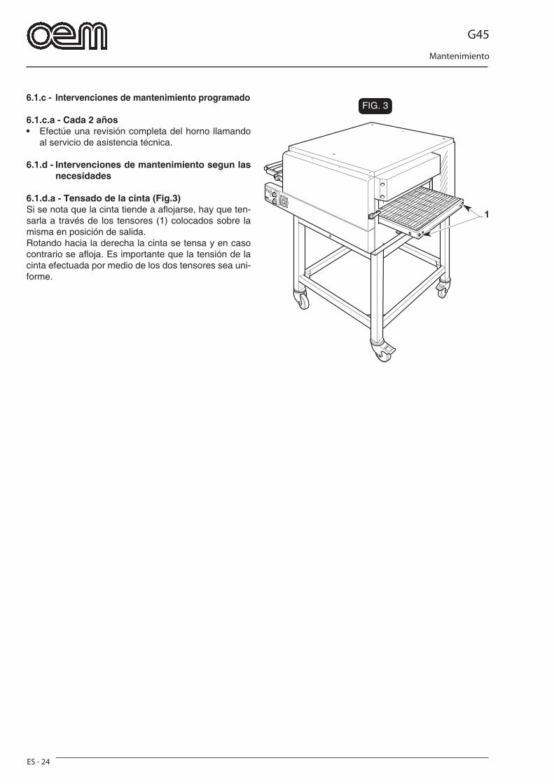
G45
Mantenimiento
ES - 24
FIG. 3
1
6.1.c - Intervenciones de mantenimiento programado
6.1.c.a - Cada 2 años• Efectúe una revisión completa del horno llamando
al servicio de asistencia técnica.
6.1.d - Intervenciones de mantenimiento segun las necesidades
6.1.d.a - Tensado de la cinta (Fig.3)Si se nota que la cinta tiende a afl ojarse, hay que ten-sarla a través de los tensores (1) colocados sobre la misma en posición de salida.Rotando hacia la derecha la cinta se tensa y en caso contrario se afl oja. Es importante que la tensión de la cinta efectuada por medio de los dos tensores sea uni-forme.
G45
Desmontaje - Desguace - Eliminación
ES - 25
Capítulo 7
7.1 - DESMONTAJE DE LA MÁQUINAEn el caso de que fuera necesario desmontar la máqui-na para instalarla posteriormente en otro lugar hay que efectuar las operaciones indicadas en el capítulo “Instalación” en sentido inverso.
PELIGRO Antes de desmontar el equipo desconecte la alimen-tación eléctrica.
Las operaciones de montaje tienen que ser efectua-das por personal técnico cualifi cado y habilitado para efectuar dichas intervenciones.
ATENCIÓN En el caso de que sea necesario desmontar la máquina o algunos de sus componentes de manera diferente a lo descrito en el manual, póngase en contacto con la empresa fabricante o con el propio Agente, consultando los datos que se encuentran en la tercera página de esta publicación.
7.2 - DESGUACE DE LA MÁQUINA
Para la salvaguardia del ambiente hay que actuar en conformidad a la normativa local vigente.Cuando el aparato no se pueda volver a utilizar ni reparar, efectuar una eliminación diferenciada de los componentes.
El aparato eléctrico no se debe eliminar como residuo urbano, si no que es necesario respetar la recolección separada de residuos introducida por la Directiva especial para la eliminación de residuos derivados de equipos eléctricos.Los aparatos eléctricos están marcados por un sím-bolo que representa un contenedor de basura sobre ruedas cruzado por una barra. El símbolo indica que el aparato fue introducido en el mercado después del 13 de agosto de 2005 y que debe ser objeto de recogida selectiva de residuos.La eliminación inadecuada o abusiva de los aparatos, o bien el uso impropio de los mismos, en razón de las sustancias y materiales que contienen, puede ser nociva para las personas y el medio ambiente. La eliminación de residuos eléctricos que no respete las normas vigentes conlleva la aplicación de sanciones administrativas y penales.
ATENCIÓN Para la eliminación de las sustancias nocivas (lubri-cantes, solventes, productos de revestimiento, etc.) consulte el párrafo siguiente.
7.3 - ELIMINACIÓN DE SUSTANCIAS NOCIVASPara eliminar las sustancias nocivas aténgase a lo establecido por las Normas Vigentes en cada país y proceda de acuerdo a las mismas.
ATENCIÓN Cualquier irregularidad cometida por el Cliente an-tes, durante o después del desguace y eliminación de los componentes de la máquina, así como al interpretar y aplicar las Normativas Vigentes en la materia, es de exclusiva responsabilità del mismo.
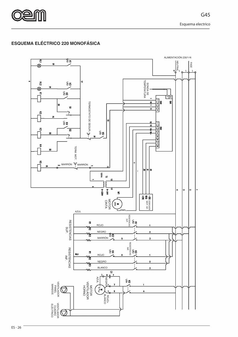
G45
Esquema electrico
ES - 26
ESQUEMA ELÉCTRICO 220 MONOFÁSICA
ALIMENTACIÓN 230/1-N
SO
ND
A D
E
TE
MP
ER
AT
UR
A
MARRÓN MARRÓNT
ER
M. M
OT
.
CODIFICADORM
OT
. M1
MO
TO
R
CIN
TA
TE
RM
OS
TA
TO
DE
SE
GU
R.
RESISTENCIAS SUP.
RE
SIS
TEN
CIA
S IN
F.
ROJO
NEGRO
MARRÓN
ROJO
NEGRO
BLANCO
AZUL
MO
TO
R
VE
NT
ILAD
OR
H
OR
NO
RO
JO+
BLA
NC
ON
EG
RO
VE
NT
ILAD
OR
P
AN
EL
MA
ND
OS
AZ
UL
VE
NT
ILAD
OR
CU
AD
RO
E
LÉC
TR
ICO
RE
SIS
TE
NC
IAS
INF
.R
ES
IST
EN
CIA
S
SU
P.
FAS
E
NE
UTR
AL
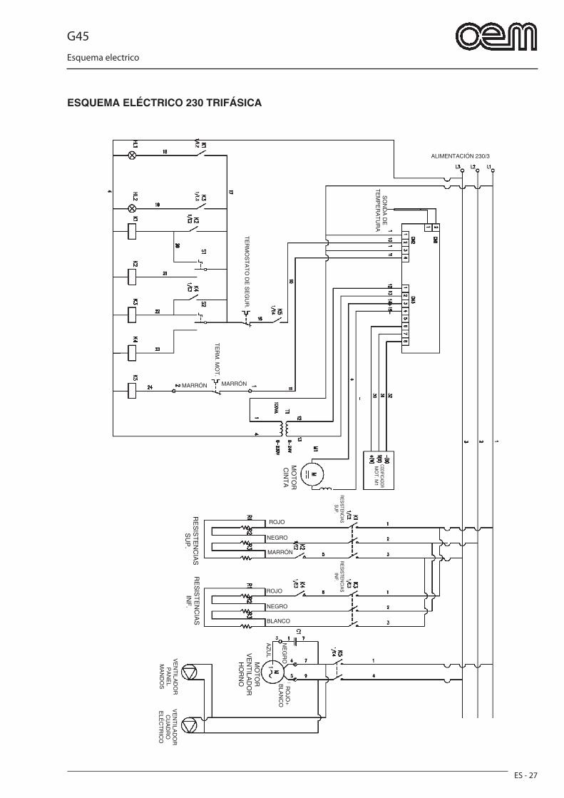
G45
Esquema electrico
ES - 27
ESQUEMA ELÉCTRICO 230 TRIFÁSICA
ALIMENTACIÓN 230/3
MARRÓN MARRÓN
TE
RM
. MO
T.
MO
TO
R
CIN
TA
TE
RM
OS
TA
TO
DE
SE
GU
R.
ROJO
NEGRO
MARRÓN
ROJO
NEGRO
BLANCO
RO
JO+
BLA
NC
ON
EG
ROVE
NT
ILAD
OR
P
AN
EL
MA
ND
OS
AZ
UL
VE
NT
ILAD
OR
CU
AD
RO
E
LÉC
TR
ICO
SO
ND
A D
E
TE
MP
ER
AT
UR
ACODIFICADORM
OT
. M1
RESISTENCIAS SUP.
RE
SIS
TE
NC
IAS
S
UP
.
RE
SIS
TEN
CIA
S IN
F.
RE
SIS
TE
NC
IAS
INF
.
MO
TO
R
VE
NT
ILAD
OR
H
OR
NO
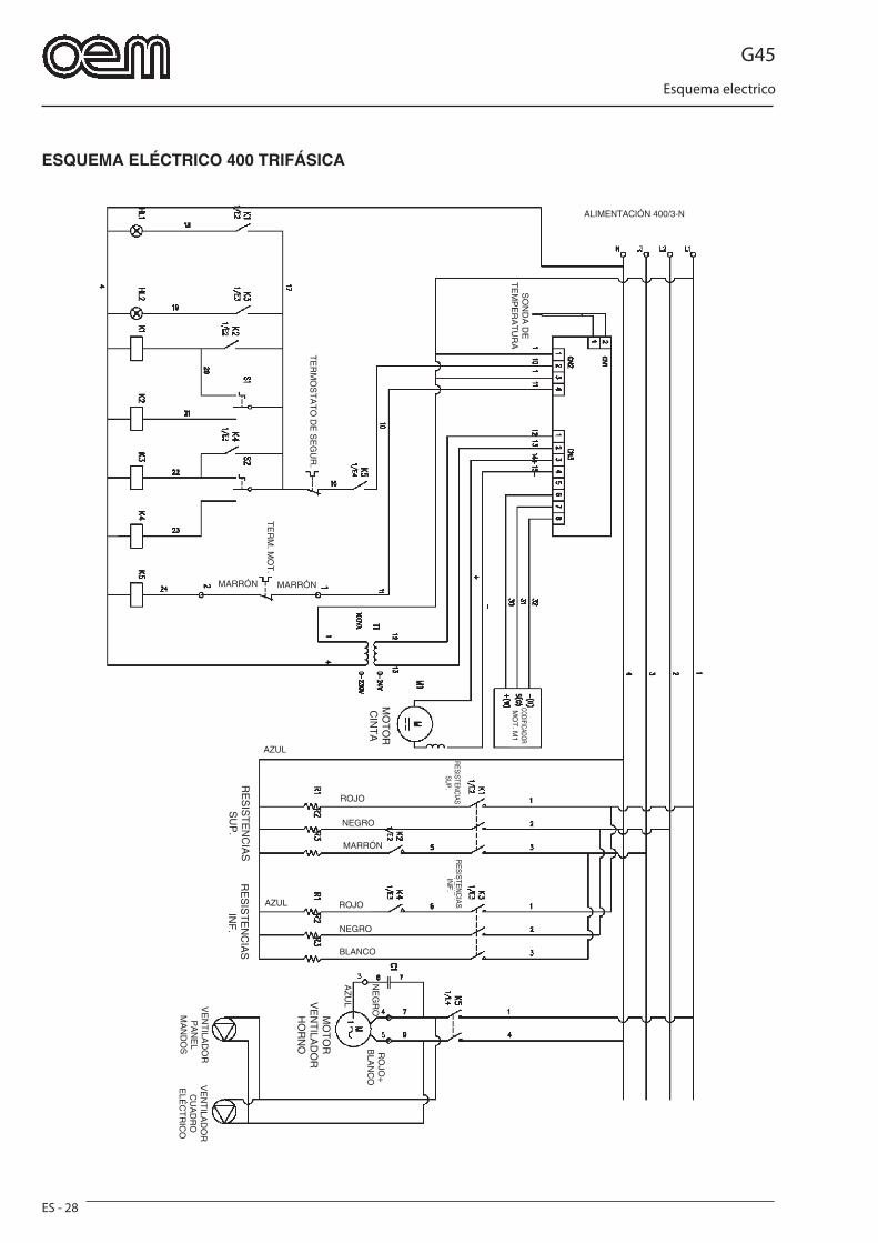
G45
Esquema electrico
ES - 28
ESQUEMA ELÉCTRICO 400 TRIFÁSICA
ALIMENTACIÓN 400/3-N
MARRÓN MARRÓN
TE
RM
. MO
T.
MO
TO
R
CIN
TA
TE
RM
OS
TA
TO
DE
SE
GU
R.
ROJO
NEGRO
MARRÓN
ROJO
NEGRO
BLANCO
AZUL
RO
JO+
BLA
NC
ON
EG
ROVE
NT
ILAD
OR
P
AN
EL
MA
ND
OS
AZ
UL
VE
NT
ILAD
OR
CU
AD
RO
E
LÉC
TR
ICO
RE
SIS
TE
NC
IAS
S
UP
.
AZUL
SO
ND
A D
E
TE
MP
ER
AT
UR
ACODIFICADORM
OT
. M1
RESISTENCIAS SUP.
RE
SIS
TEN
CIA
S IN
F.
RE
SIS
TE
NC
IAS
INF
.
MO
TO
R
VE
NT
ILAD
OR
H
OR
NO
G45
Esquema electrico
ES - 29
LEYENDA
K1 = Telerruptor principal resistencia superiorK2 = Telerruptor economía resistencia superiorK3 = Telerruptor principal resistencia inferiorK4 = Telerruptor economía resistencia inferiorK5 = Telerruptor ventilador hornoHL1 = Lámpara indicadora resistencia superior conectadaHL2 = Lámpara indicadora resistencia inferior conectadaS1 = Selector resistencia superiorS2 = Selector resistencia inferiorT1 = Transformador 0-230/0-24V alimentación esquema mandos