formal requirements - uomustansiriyah.edu.iq04_50... · 1- cardinality 2- modality . al-...
TRANSCRIPT
AL- Mustansirya University Course: Software Engineering
College of Education Lecturer: Iman Hussein
Department of Computer Science Third Class
1
CHAPTER 4
Formal Requirements
Topics:
4.1 Analysis Model
4.2 Analysis Model Objectives
- Elements of Analysis Model
4.3 Data Model
4.4 Creating an Entity/Relationship Model
4.5 Creating a Data Flow Model
AL- Mustansirya University Course: Software Engineering
College of Education Lecturer: Iman Hussein
Department of Computer Science Third Class
2
1.4 Analysis Model The analysis model, actually a set of models, is the first technical representation of a
system. Over the years many methods have been proposed for analysis modeling.
However, two now dominate. The first, structured analysis, is a classical modeling
method and is described in this chapter. The other approach, object oriented analysis.
. للنظام ا�ول )التقني( الفني التمثيل ھوو ،)models( النماذج من مجموعةھو )analysis model(التحليل نموذج
طريقتين مستخدمة مواھ ,. )analysis model(التحليل لنمذجة ا�ساليب من العديد راح تتم اق، السنوات مدى وعلى وسوف نتناولھا )التقليدية( الك4سيكية النمذجة سلوبا ھو و) structured analysis( التحليل الھيكلي: او� ھما
.)object oriented analysis( التحليل الشيئي: ثانيا . الفصل ھذا في
: Structured Analysisالتحليل الھيكلي ھو عملية تھدف لدراسة النظام بغية معرفة طريقة أدائه لعمله والمشاكل التي تعترضه وتحديد المتطلبات وذلك
بأستخدام ادوات التحليل )Structured Methodology( )الھرمية(بأستخدام منھجية التفكيك والتجزئة الھيكلية .الھيكلية للنظام الحالي والمقترح
: )object oriented analysis(التحليل الشيئي .)Objects(و الكائنات )Classes(ھو طريقة للتعامل مع المتطلبات من وجھه نظر الفصائل
4.2 Analysis Model Objectives:
The analysis model must achieve three primary objectives:
(1) to describe what the customer requires,
(2) to establish a basis for the creation of a software design, and
(3) to define a set of requirements that can be validated once the software is built. To
accomplish these objectives, the analysis model derived during structured analysis takes
the form illustrated in Figure (4.1)
)bjectivesOodel Mnalysis A( اھداف نموذج التحليل
:ھي رئيسية أھداف ث!ثةب ھاتحقيق يجب تحليلال نموذج الزبون مطالب بوصف يقوم )1(
Software الـ تصميم أو تكوين لعملية قاعدة بناء )2(
.بناءھا تم ما متى حفظھا Software الـ على يجب التي Requirements المتطلبات من مجموعة تعريف) 3(
structured(الھيكلي تحليلال خ4ل المتحقق )analysis model(تحليلال نموذج ا�ھداف، ھذه تحقيقول
analysis( مخطط ال في موضحال الشكل يأخذ)4.1(.
AL- Mustansirya University Course: Software Engineering
College of Education Lecturer: Iman Hussein
Department of Computer Science Third Class
3
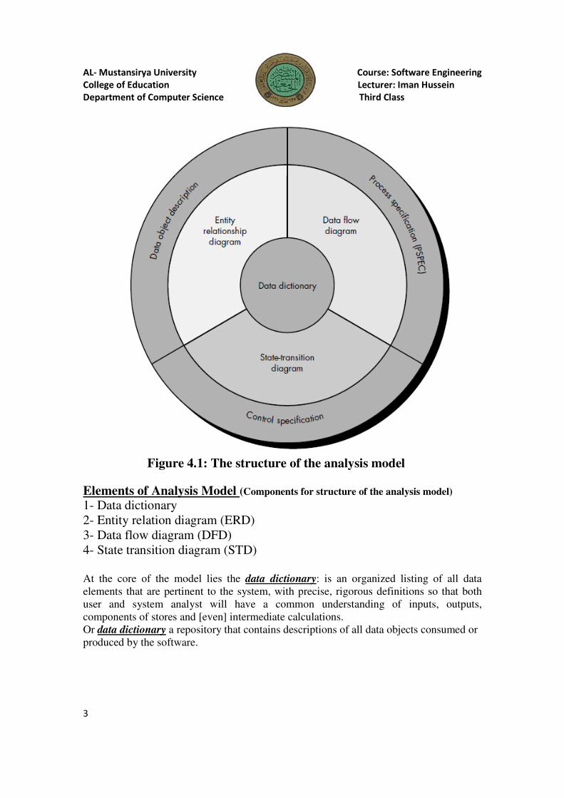
Figure 4.1: The structure of the analysis model
Elements of Analysis Model (Components for structure of the analysis model)
1- Data dictionary
2- Entity relation diagram (ERD)
3- Data flow diagram (DFD)
4- State transition diagram (STD)
At the core of the model lies the data dictionary: is an organized listing of all data
elements that are pertinent to the system, with precise, rigorous definitions so that both
user and system analyst will have a common understanding of inputs, outputs,
components of stores and [even] intermediate calculations.
Or data dictionary a repository that contains descriptions of all data objects consumed or
produced by the software.
AL- Mustansirya University Course: Software Engineering
College of Education Lecturer: Iman Hussein
Department of Computer Science Third Class
4
Three different diagrams surround the core:
1- The entity relationship diagram (ERD) depicts relationships between data objects.
The ERD is the notation that is used to conduct the data modeling activity. The attributes
of each data object noted in the ERD can be described using a data object description.
2- The data flow diagram (DFD) : is a graphical representation that depicts information
flow and the transforms that are applied as data move from input to output. The basic
form of a data flow diagram, also known as a data flow graph or a bubble chart.
serves two purposes: (1) to provide an indication of how data are transformed as they
move through the system and (2) to depict the functions (and sub functions) that
transform the data flow. The DFD provides additional information that is used during the
analysis of the information domain and serves as a basis for the modeling of function. A
description of each function presented in the DFD is contained in a process
specification (PSPEC).
DFD are used to represent data and the processes that manipulate it.
3- State transition diagram (STD ): By studying the STD, a software engineer can
determine the behavior of the system and, more important, can ascertain whether there
are "holes" in the specified behavior. STD is a behavioral model
The STD indicates how the system behaves as a consequence of external events. To
accomplish this, the STD represents the various modes of behavior (called states) of the
system and the manner in which transitions are made from state to state. The STD serves
as the basis for behavioral modeling. Additional information about the control aspects
of the software is contained in the control specification (CSPEC).
Data object Description: The attributes of each data object noted in the ERD can be
described using a data object description.
In other word: incorporates the data object and all of its attributes.
Process Specification (PSPEC): is used to describe all flow model processes that appear
at the final level of refinement. The content of the process specification can include
narrative text, a program design language (PDL) description of the process algorithm,
mathematical equations, tables, diagrams, or charts.
The control specification (CSPEC): represents the behavior of the system in two
different ways. The CSPEC contains a state transition diagram that is a sequential
specification of behavior. It can also contain a program activation table—a combinatorial
specification of behavior.

AL- Mustansirya University Course: Software Engineering
College of Education Lecturer: Iman Hussein
Department of Computer Science Third Class
5
CSPEC is used to indicate (1) how the software behaves when an event or control signal
is sensed and (2) which processes are invoked as a consequence of the occurrence of the
event.
:عناصر نموذج التحليل
Elements of Analysis Model (Components for structure of the analysis model)
1- Data dictionary
2- Entity relation diagram (ERD)
3- Data flow diagram (DFD)
4- State transition diagram (STD)
) كائنات(قائمة او مستودع لكافة عناصرالبيانات : )data dictionary(قاموس البيانات يكمن النموذج مركز في
)data objects ( الخاصة بالمنظومة او وصف لمخازن البيانات وانسيابھا والموجودة في مخططDFD .
.البرنامج قبل من المنتجة أو المستھلكة البيانات الكائنات لكافة وصف على يحتوي مستودعاو -
:) data dictionary(مركزال تحيط مختلفة مخططات ث!ثةھناك - )entity relation diagram (ERD)(ائنات الع4ئقية الك مخطط -1
)data flow diagram (DFD(() تدفق البيانات(مخطط انسياب البيانات -2
)state transition diagram (STD((مخطط انتقال الحالة -3
: ) entity relation diagram(ERD)(ائنات الع!ئقية الك مخطط -1
بداية صحيحة من قبل محلل النظم ) ERD )Entity Relationship Diagramيعتبر مخطط الكائنات الع4ئقية ويتكون مخطط الكائنات الع4ئقية .الخاصة بالمنظومة تحت اXعداد Data Requirementsلفھم متطلبات البيانات
بين ھذه الكائنات Relationshipsوالع4قة data objectمن اشكال ھندسية تشبه المخطط اXنسيابي تبين الكائنات .انات ويعتبر ھذا المخطط أيضا أساسا لتصميم قاعدة البي.لكل كائن أو ع4قة Attributesوايضا الخصائص
) :iagram (DFDDlow Fata D(() تدفق البيانات(مخطط انسياب البيانات -2وھو مخطط ھيكلي رسومي يبين صورة لحركة انسياب البيانات داخل النظام بين مخازن البيانات والمعالجة
تدفقل البياني الرسم )Bubble chart أو Flow graph( باسم يعرف DFD للـ ا�ساسي الشكل إن .والكيانات الخارجية
.فقاعةال مخطط أو البيانات
، يوضح الدوال التي تقوم ثانيا. ، يعطينا مؤشرات حول كيفية انتقال البيانات خ4ل النظاماو� :يستخدم لغرضين .بتناقل البيانات او تحويل البيانات
:)iagram (STDDransition Ttate S((مخطط انتقال الحالة -3 ھناك كانت إذا مما التأكد يمكن وا�ھم، النظام، سلوك تحديد من البرمجيات مھندس يستطيع STD دراسة خ4ل من
.محدد سلوك في ثغرات
أنماط مختلف STD يمثل ذلك، ولتحقيق. خارجية �حداث نتيجة النظام بھا يتصرف التي الطريقة الىSTD شيروي
السلوكية للنماذج كأساس STD يقدم. أخرى إلى حالة من اXنتقال ريقةطو لنظامل) statesحاXت ىدعت( السلوك
)behavioral modeling( .
Data object Description :الصفات أو الخصائص وضع عملية ھيattributes لكل data object.
AL- Mustansirya University Course: Software Engineering
College of Education Lecturer: Iman Hussein
Department of Computer Science Third Class
6
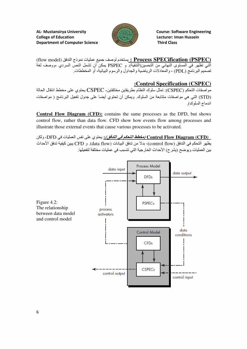
ification (PSPEC)SPECrocess P :لتدفقا نموذج عمليات جميع لوصف يستخدم )flow model(
لغة ووصف، السردي النص تشمل أن يمكن PSPECو ).التنقية(تحسينال من النھائي المستوى في تظھر التي
. المخططات أو البيانية، والرسوم والجداول الرياضية والمعادXت ،) PDL( برنامجال تصميم
pecification (CSPEC)Sontrol C: الحالة انتقال مخطط على يحتوي CSPEC ،مختلفتين بطريقتين النظام سلوك تمثل): CSPEC( التحكم مواصفات
)STD( برنامجال تفعيلجدول على أيضا تحتوي أن ويمكن. السلوك من متتابعة مواصفات ھي التي ) مواصفات
.)السلوك اندماج
Control Flow Diagram (CFD): contains the same processes as the DFD, but shows
control flow, rather than data flow. CFD show how events flow among processes and
illustrate those external events that cause various processes to be activated.
) Control Flow Diagram (CFD ) في العمليات نفس على يحتوي :)التدفقمخطط التحكم في DFD، ولكن
ا�حداث تدفق كيفيةيبين CFDو .)data flow( البيانات تدفق من بدX ،)control flow( التدفق في التحكم يظھر
.لتفعيلھا مختلفة عمليات في تتسبب التي الخارجية ا�حداث )شرحي( وضحيو العمليات بين
Figure 4.2:
The relationship
between data model
and control model
AL- Mustansirya University Course: Software Engineering
College of Education Lecturer: Iman Hussein
Department of Computer Science Third Class
7
4.3 Data Model :
The data model consists of three interrelated pieces of information:
1- Data object (input and output from a system)
2- Attributes that describe the data object
3- Relationships that connect data objects to one another.
1- Data object : A data object is a representation of almost any composite information
that must be understood by software. By composite information, we mean something that
has a number of different properties or attributes. A data object can be an external entity
(e.g., anything that produces or consumes information), a thing (e.g., a report or a
display), an occurrence (e.g., a telephone call) or event (e.g., an alarm), a role (e.g.,
salesperson), an organizational unit (e.g., accounting department), a place (e.g., a
warehouse), or a structure (e.g., a file). A data object encapsulates data only—there is no
reference within a data object to operations that act on the data.
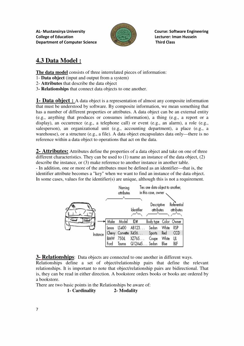
2- Attributes: Attributes define the properties of a data object and take on one of three
different characteristics. They can be used to (1) name an instance of the data object, (2)
describe the instance, or (3) make reference to another instance in another table.
- In addition, one or more of the attributes must be defined as an identifier—that is, the
identifier attribute becomes a "key" when we want to find an instance of the data object.
In some cases, values for the identifier(s) are unique, although this is not a requirement.
3- Relationships: Data objects are connected to one another in different ways.
Relationships define a set of object/relationship pairs that define the relevant
relationships. It is important to note that object/relationship pairs are bidirectional. That
is, they can be read in either direction. A bookstore orders books or books are ordered by
a bookstore.
There are two basic points in the Relationships be aware of:
1- Cardinality 2- Modality

AL- Mustansirya University Course: Software Engineering
College of Education Lecturer: Iman Hussein
Department of Computer Science Third Class
8
1- Cardinality: the specification of the number of occurrences of one [object] that can
be related to the number of occurrences of another [object]. Cardinality is usually
expressed as simply 'one' or 'many.'
Taking into consideration all combinations of 'one' and 'many,' two [objects] can be
related as :
• One-to-one (l:l)—An occurrence of [object] 'A' can relate to one and only one
occurrence of [object] 'B,' and an occurrence of 'B' can relate to only one occurrence of
'A.'
• One-to-many (l:N)—One occurrence of [object] 'A' can relate to one or many
occurrences of [object] 'B,' but an occurrence of 'B' can relate to only one occurrence of
'A.' For example, a mother can have many children, but a child can have only one mother.
• Many-to-many (M:N)—An occurrence of [object] 'A' can relate to one or more
occurrences of 'B,' while an occurrence of 'B' can relate to one or more occurrences of 'A.'
For example, an uncle can have many nephews, while a nephew can have many uncles.
2- Modality: The modality of a relationship is 0 if there is no explicit need for the
relationship to occur or the relationship is optional. The modality is 1 if an occurrence of
the relationship is mandatory.
:تحتوي على ث4ث قطع مترابطة من المعلومات : )Data Model(نمذجة البيانات - )النظام من والمخرجات المدخ4ت( : Data object البيانات كائن -1 البيانات كائن تصف التي: Attributes الصفات -2
.البعض بعضھا إلى البيانات كائنات تربط التي: Relationships الع4قات -3
Data Object : ي مجموعة من المعلومات تلك التي يجب على الـ�نعني . أن يتفھمھا Softwareھو تمثيل Dataممكن أن يكون الـ . بمجموعة المعلومات شيء ما يحتوي على عدد مختلف من الخصائص أو الصفات
Object تقرير مث4(تواجد ، ) أي شيء يستھلك أو ينتج معلوماتمث4 (ھو كيان خارجيreport ( ، حدث) مث4
) .Fileملف (ھيكل ، ) depositoryمخزن (مكان ، ) الشخص البائع(دور ، ) إنذار
عن Objectحيث X يوجد إشارة داخل الـ Encapsulate )يشفر البيانات(يغلف البيانات فقط Data Objectإن الـ .ماھية العمليات التي ممكن أن تعمل على تلك البيانات
AL- Mustansirya University
College of Education
Department of Computer Science
9
- :الذي يأخذ واحد من الفروع الث4ثة
ھنالك ، مترابطة احدھا مع اhخر عن طريق اتجاھات مختلفة 2- Modality
.الع4قة عن كافية معلومات
). many or one(في ع4قة وتأخذ قيمتين
تكون أن يمكن )two objects(بين كائنين
optional ( و واحد إذا كانت الع4قة موجبة
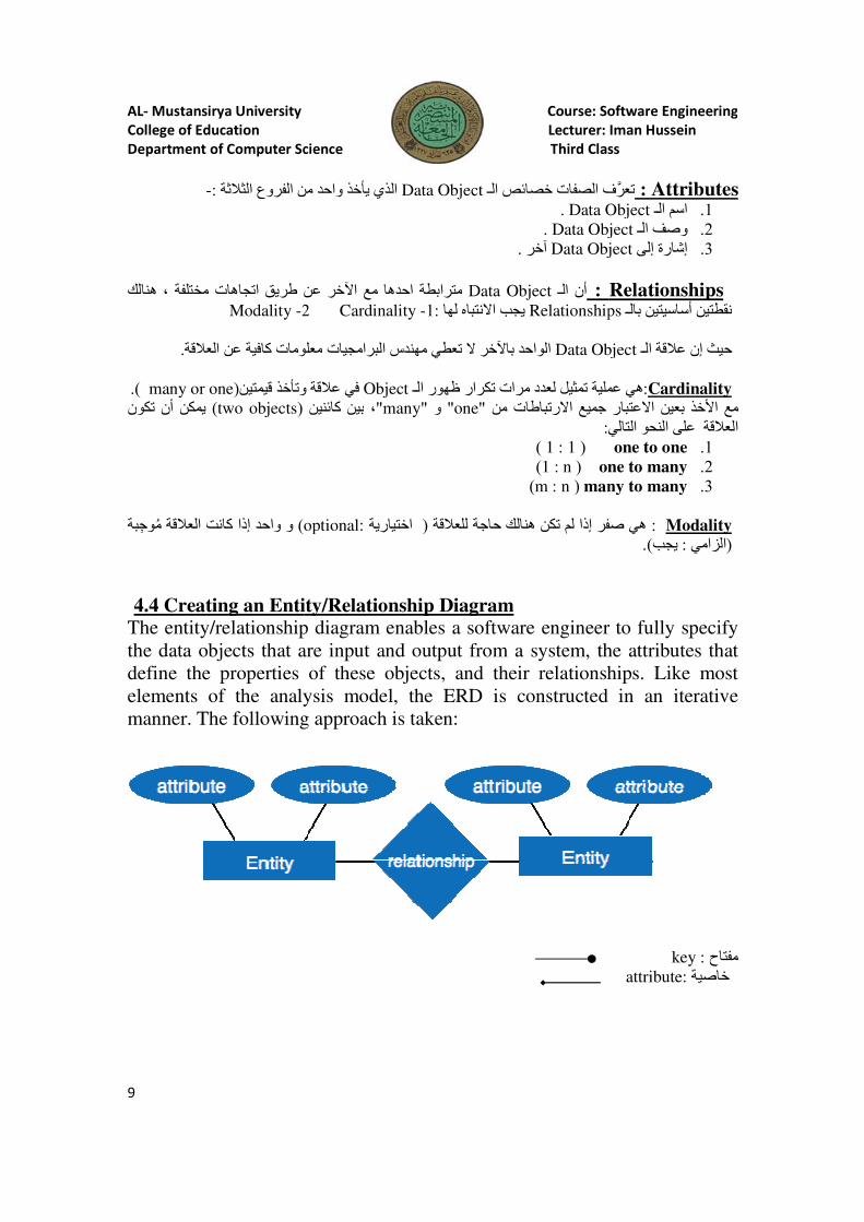
4.4 Creating an Entity/Relationship DiagramThe entity/relationship diagram enables a software engineer to fully specify
the data objects that are input and output from a system, the attributes that
define the properties
elements of the analysis
manner. The following approach is
Mustansirya University Course: Software Engineering
College of Education Lecturer: Iman Hussein
Department of Computer Science Third Class
الذي يأخذ واحد من الفروع الث4ثة Data Objectتعرف الصفات خصائص الـ Data Object .
Data Object . Data Object آخر.
مترابطة احدھا مع اhخر عن طريق اتجاھات مختلفة Data Objectأن الـ : Relationships نتباه لھاX1:يجب ا- Cardinality 2
Data Object خر الواحدhبا X معلومات البرامجيات مھندس تعطي
في ع4قة وتأخذ قيمتين Objectعملية تمثيل لعدد مرات تكرار ظھور الـ بين كائنين ،"many" و" one" من اXرتباطات جميع :التالي
)1 : 1 (
one to many )1 : n (
many to many )m : n (
optional:اختيارية ( ھي صفر إذا لم تكن ھنالك حاجة للع4قة
Creating an Entity/Relationship Diagram The entity/relationship diagram enables a software engineer to fully specify
objects that are input and output from a system, the attributes that
of these objects, and their relationships. Like most
elements of the analysis model, the ERD is constructed in an iterative
manner. The following approach is taken:
Course: Software Engineering
Lecturer: Iman Hussein
Third Class
Attributes : تعرف الصفات خصائص الـData Objectاسم الـ .1
Data Objectوصف الـ .2
Data Objectإشارة إلى .3
Relationships Relationshipsنقطتين أساسيتين بالـ
Data Object الـ ع4قة إن حيث
Cardinality:عملية تمثيل لعدد مرات تكرار ظھور الـ ھي اXعتبار بعين ا�خذ مع
التالي النحو على الع4قة 1. one to one 2. one to many
3. many to many
Modality : ھي صفر إذا لم تكن ھنالك حاجة للع4قة .)يجب: الزامي (
The entity/relationship diagram enables a software engineer to fully specify
objects that are input and output from a system, the attributes that
of these objects, and their relationships. Like most
model, the ERD is constructed in an iterative
key : مفتاح attribute: خاصية
AL- Mustansirya University Course: Software Engineering
College of Education Lecturer: Iman Hussein
Department of Computer Science Third Class
10
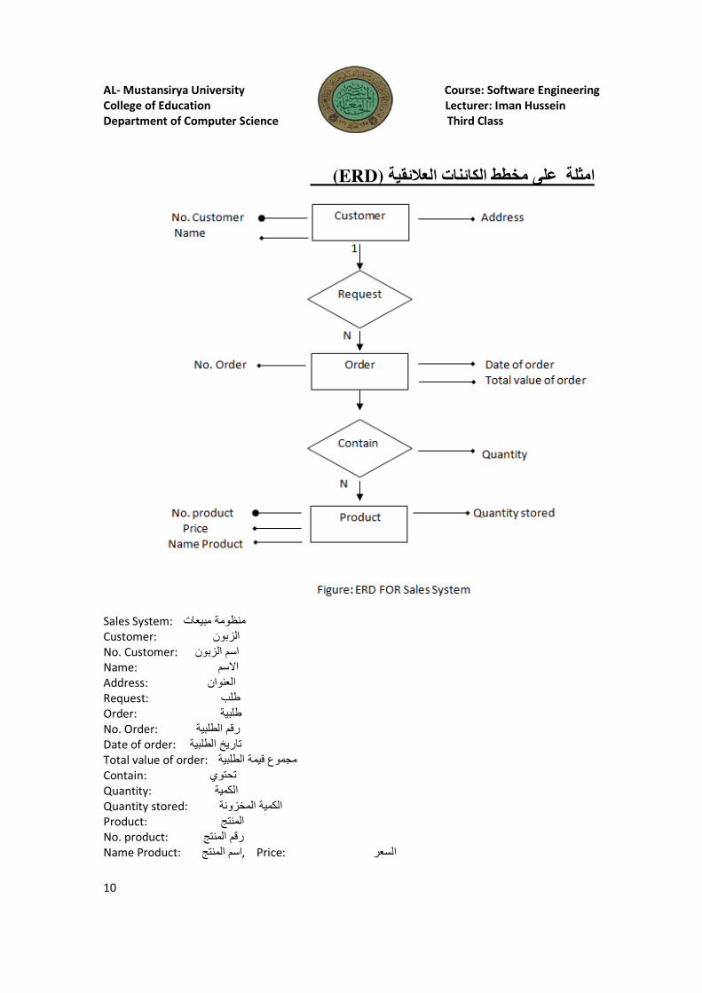
)ERD( الع!ئقية الكائنات مخططعلى امثلة
Sales System: منظومة مبيعات Customer: الزبون No. Customer: اسم الزبون
Name: سم� اAddress: العنوان Request: طلب
Order: طلبية
No. Order: رقم الطلبية
Date of order: تاريخ الطلبية Total value of order: مجموع قيمة الطلبية
Contain: تحتوي Quantity: الكمية
Quantity stored: الكمية المخزونة Product: المنتج No. product: رقم المنتج
Name Product: :Price , اسم المنتج السعر
AL- Mustansirya University Course: Software Engineering
College of Education Lecturer: Iman Hussein
Department of Computer Science Third Class
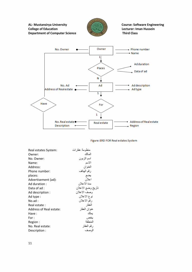
11
Real estates System: منظومة عقارات Owner: المالك No. Owner: اسم الزبون
Name: ا�سم
Address: العنوان Phone number: رقم الھاتف
places: يضع Advertisement (ad): اع/ن
Ad duration : ع/ن�مدة ا
Data of ad : ع/ن� تأريخ وضع اAd description : ع/ن�وصف ا
Ad type : ع/ن� نوع ا
No.ad : ع/ن� رقم ا
Real estate : العقار Address of Real estate: العقار عنوان
Have : يملك
For : يخص Region : المنطقة No. Real estate: رقم العقار
Description : الوصف
AL- Mustansirya University Course: Software Engineering
College of Education Lecturer: Iman Hussein
Department of Computer Science Third Class
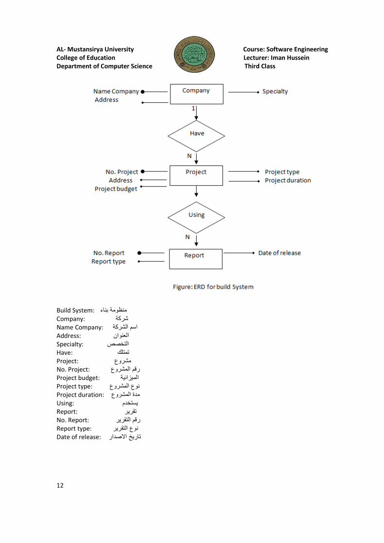
12
Build System: منظومة بناء Company: شركة
Name Company: اسم الشركة
Address: العنوان Specialty: التخصص Have: تمتلك Project: مشروع
No. Project: رقم المشروع
Project budget: الميزانية Project type: نوع المشروع
Project duration: مدة المشروع
Using: يستخدم Report: تقرير No. Report: لتقرير رقم ا
Report type: نوع التقرير
Date of release: � صدارتاريخ ا
AL- Mustansirya University
College of Education
Department of Computer Science
13
4.5 Creating a Data Flow ModelA few simple guidelines can aid immeasurably during derivation of a data flow
(1) the level 0 data flow
(2) primary input and output should be carefully noted; (3) Refinement should begin by isolating candidate processes, data objects, and stores to
be represented at the next level;
(4) All arrows and bubbles should be labeled with meaningful
(5) Information flow continuity must be maintained from level to level, and
(6) One bubble at a time should be refined. There is a natural tendency to overcomplicate
the data flow diagram.
Creating a Data Flow Model: (
data flow diagram وھي:
.بفقاعة مفردة
Function ،data object و الـdata
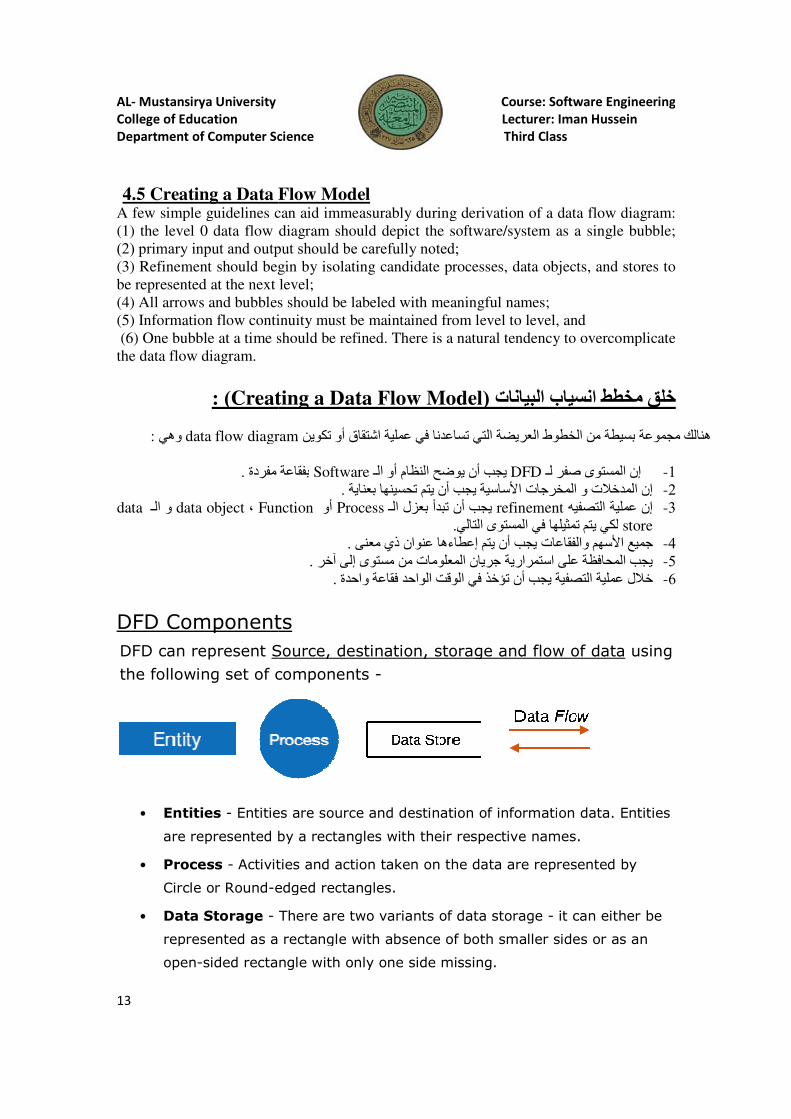
DFD Components
DFD can represent Source, destination, storage and flow of data
the following set of components
• Entities - Entities are source and
are represented by a rectangles with their respective names.
• Process - Activities and action taken on the data are represented by
Circle or Round-edged rectangles.
• Data Storage -
represented as a rectangle with absence of both smaller sides or as an
open-sided rectangle with only one side missing.
Mustansirya University Course: Software Engineering
College of Education Lecturer: Iman Hussein
Department of Computer Science Third Class
Creating a Data Flow Model A few simple guidelines can aid immeasurably during derivation of a data flow
(1) the level 0 data flow diagram should depict the software/system as a
(2) primary input and output should be carefully noted; should begin by isolating candidate processes, data objects, and stores to
at the next level;
ws and bubbles should be labeled with meaningful names;
(5) Information flow continuity must be maintained from level to level, and
(6) One bubble at a time should be refined. There is a natural tendency to overcomplicate
Creating a Data Flow Model(خلق مخطط انسياب البيانات
data flow diagramھنالك مجموعة بسيطة من الخطوط العريضة التي تساعدنا في عملية اشتقاق أو تكوين
بفقاعة مفردة Softwareيجب أن يوضح النظام أو الـ DFDإن المستوى صفر لـ .ا�ساسية يجب أن يتم تحسينھا بعناية خرجات
refinement يجب أن تبدأ بعزل الـProcess أوFunction
.لكي يتم تمثيلھا في المستوى التالي
.جميع ا�سھم والفقاعات يجب أن يتم إعطاءھا عنوان ذي معنى
.جريان المعلومات من مستوى إلى آخر يجب المحافظة على استمرارية
.خ4ل عملية التصفية يجب أن تؤخذ في الوقت الواحد فقاعة واحدة
DFD Components
Source, destination, storage and flow of data
the following set of components -
Entities are source and destination of information data. Entities
are represented by a rectangles with their respective names.
Activities and action taken on the data are represented by
edged rectangles.
There are two variants of data storage -
represented as a rectangle with absence of both smaller sides or as an
sided rectangle with only one side missing.
Course: Software Engineering
Lecturer: Iman Hussein
Third Class
A few simple guidelines can aid immeasurably during derivation of a data flow diagram:
diagram should depict the software/system as a single bubble;
should begin by isolating candidate processes, data objects, and stores to
(5) Information flow continuity must be maintained from level to level, and
(6) One bubble at a time should be refined. There is a natural tendency to overcomplicate
خلق مخطط انسياب البيانات
ھنالك مجموعة بسيطة من الخطوط العريضة التي تساعدنا في عملية اشتقاق أو تكوين
إن المستوى صفر لـ -1خرجات لمدخ4ت و االمإن -2refinementيه فإن عملية التص -3
store لكي يتم تمثيلھا في المستوى التاليجميع ا�سھم والفقاعات يجب أن يتم إعطاءھا عنوان ذي معنى -4يجب المحافظة على استمرارية -5خ4ل عملية التصفية يجب أن تؤخذ في الوقت الواحد فقاعة واحدة -6
Source, destination, storage and flow of data using
destination of information data. Entities
are represented by a rectangles with their respective names.
Activities and action taken on the data are represented by
it can either be
represented as a rectangle with absence of both smaller sides or as an
AL- Mustansirya University Course: Software Engineering
College of Education Lecturer: Iman Hussein
Department of Computer Science Third Class
14
External Entity
Process
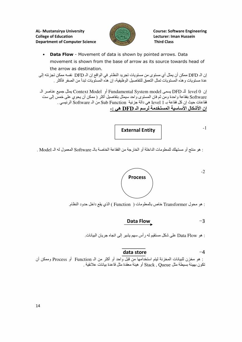
• Data Flow - Movement of data is shown by pointed arrows. Data
movement is shown from the base of arrow as its source towards head of
the arrow as destination.
نفسه ممكن تجزئته إلى DFDفي الواقع إن الـ . ممكن أن يمثل أي مستوى من مستويات تجريد النظام DFDإن الـ .إن ھذه المستويات تبدأ من الصفر فأكثر ، عدة مستويات وھذه المستويات تمثل التعمق للتفاصيل الوظيفية
يمثل جميع عناصر الـ Context Modelأو Fundamental System model يسمى DFDللـ level 0إن Software ممكن أن يحوي على خمس إلى ست ( بفقاعة واحدة ومن ثم فان المستوى واحد سيمثل بتفاصيل أكثر
.سي الرئي Softwareمن الـ Sub Functionھي دالة جزئية level 1فقاعات حيث إن كل فقاعة بـ
-:ھي DFDإن اJشكال اJساسية المستخدمة لرسم الـ
1-
. Modelالمعمول له الـ Softwareھو منتج أو مستھلك للمعلومات الداخلة أو الخارجة من الفقاعة الخاصة بالـ :
2-
.الذي يقع داخل حدود النظام) Function( خاص بالمعلومات Transformerھو محول :
3 � Data Flow
.على شكل مستقيم له رأس سھم يشير إلى اتجاه جريان البيانات Data Flowھو :
4 � data store
وممكن أن Processأو Functionھو مخزن للبيانات المخزنة ليتم استخدامھا من قبل واحد أو أكثر من الـ : .أو ھيئة معقدة مثل قاعدة بيانات ع4ئقية Stack , Queueتكون بھيئة بسيطة مثل
AL- Mustansirya University
College of Education
Department of Computer Science
15
online shopping sy(
Levels of DFD
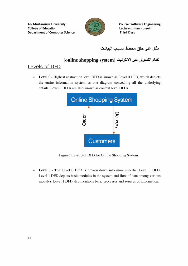
• Level 0 - Highest abstraction level DFD is known as Level 0 DFD, which depicts
the entire information system as one diagram concealing all the underlying
details. Level 0 DFDs are also known as context level DFDs.
Figure
• Level 1 - The Level 0 DFD is broken down into more specific, Level 1 DFD.
Level 1 DFD depicts basic modules in the system and flow of data among various
modules. Level 1 DFD also
Mustansirya University Course: Software Engineering
College of Education Lecturer: Iman Hussein
Department of Computer Science Third Class
مثال على خلق مخطط انسياب البيانات
online shopping system(عبر ا�نترنيت
Highest abstraction level DFD is known as Level 0 DFD, which depicts
the entire information system as one diagram concealing all the underlying
details. Level 0 DFDs are also known as context level DFDs.
Figure: Level 0 of DFD for Online Shopping System
The Level 0 DFD is broken down into more specific, Level 1 DFD.
Level 1 DFD depicts basic modules in the system and flow of data among various
modules. Level 1 DFD also mentions basic processes and sources of information.
Course: Software Engineering
Lecturer: Iman Hussein
Third Class
مثال على خلق مخطط انسياب البيانات
عبر ا�نترنيت نظام التسوق
Highest abstraction level DFD is known as Level 0 DFD, which depicts
the entire information system as one diagram concealing all the underlying
ystem
The Level 0 DFD is broken down into more specific, Level 1 DFD.
Level 1 DFD depicts basic modules in the system and flow of data among various
mentions basic processes and sources of information.
AL- Mustansirya University
College of Education
Department of Computer Science
16
Figure
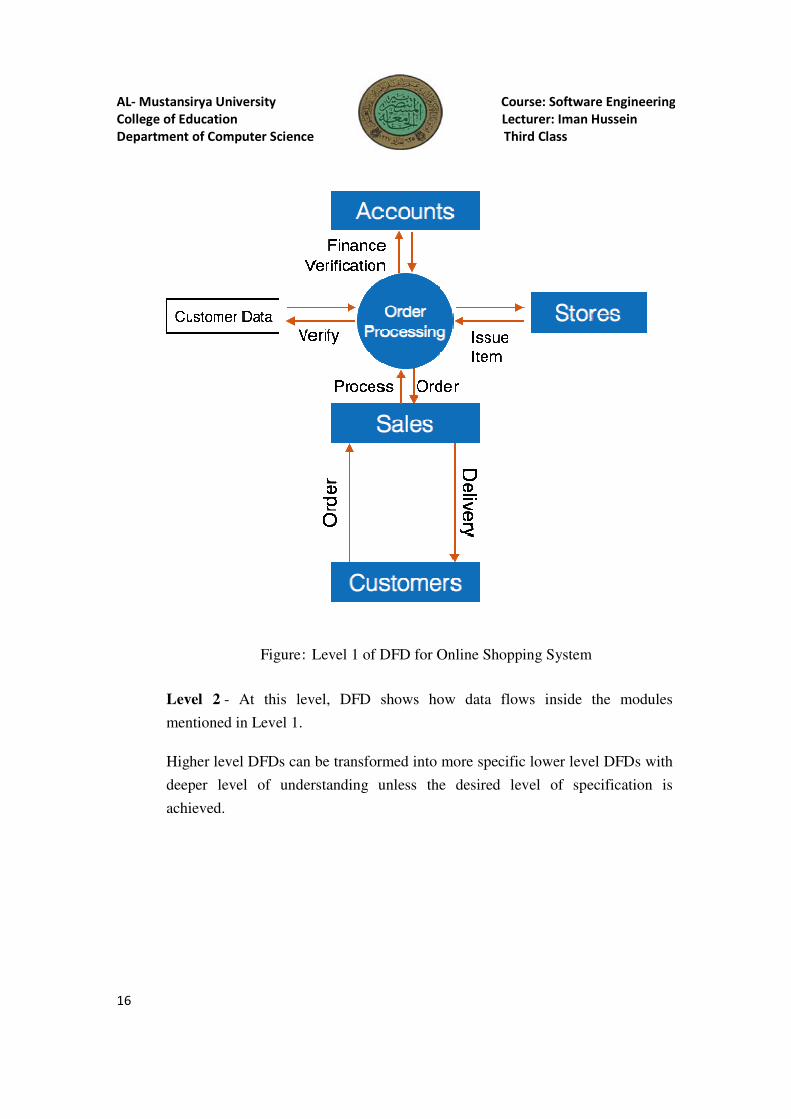
Level 2 - At this level, DFD shows how data flows inside the modules
mentioned in Level 1.
Higher level DFDs can be transformed into more specific lower level DFDs with
deeper level of understanding unless the desired level of specification is
achieved.
Mustansirya University Course: Software Engineering
College of Education Lecturer: Iman Hussein
Department of Computer Science Third Class
Figure: Level 1 of DFD for Online Shopping System
At this level, DFD shows how data flows inside the modules
in Level 1.
Higher level DFDs can be transformed into more specific lower level DFDs with
deeper level of understanding unless the desired level of specification is
Course: Software Engineering
Lecturer: Iman Hussein
Third Class
ystem
At this level, DFD shows how data flows inside the modules
Higher level DFDs can be transformed into more specific lower level DFDs with
deeper level of understanding unless the desired level of specification is