for copper for electrical - zinoglobal · british bronze and brass ingot manufacturers’...
TRANSCRIPT
B S I B S X 4 1 0 7 70 = Lb24bbï 0407426 762
-
BRITISH STANDARD 4109 : 1970 UDC' 1669.3 + 669.3 4261 -621.315.3
CONFIRMED AUGUST 1985
SPECIFICATION FOR
COPPER FOR ELECTRICAL PURPOSES
WIRE FOR GENERAL ELECTRICAL PURPOSES AND FOR INSULATED
CABLES AND FLEXIBLE CORDS
BRITISH STANDARDS INSTITUTION
www.TeraStandard.com
--`,`````,``````,,`,`,,,,`,,``,`-`-`,,`,,`,`,,`---
BSI B S * 4 L 0 9 70 Lb24669 0409427 b T î
SPECIFICATION FOR
COPPER FOR ELECTRICAL PURPOSES
WIRE FOR GENERAL ELECTRICAL PURPOSES AND FOR INSULATED CABLES AND FLEXIBLE
CORDS
BS 4109 : 1970
Incorporat ing amendment issued August 1978 (AMD 27 15)
CONFIRMED AUGUST 1985
B R I T I S H S T A N D A R D S I N S T I T U T I O N Incorporated by Royal Charter
2 P A R K S T R E E T , L O N D O N WIA 2BS Telex : 26693 3 Telephone: O1 -629 9000
www.TeraStandard.com
--`,`````,``````,,`,`,,,,`,,``,`-`-`,,`,,`,`,,`---
BSI BSJt4109 7 0 = II624669 0409428 535 W
BS 4109 11970
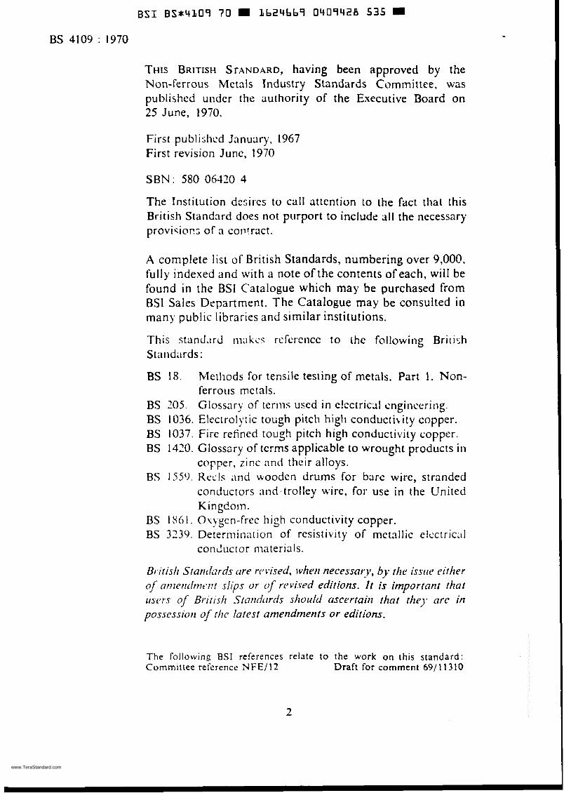
THIS BRITISH STANDARD, having been approved by the Non-ferrous Metais industry Standards Committee, was published uiidcr the authority of the Executive Board on 25 June, 1970.
First publishcd January, 1967 First revision June, 1970
SBN : 580 06420 4
The Institution desires to call attention to the fact that this British Standard does not purport to include rill the necessary provisiors of n coiif.ract.
A compiete list of British Standards, numbering over 9,000, fully indexed and with a note of the contents of each, will be found in the BSI Catalogue which may be purchased from BSI Sales Department. The Catalogue may be consulted ¡o many public libraries and similar institutions.
This standilrd iii;ikzs rercrciice to the followi~~g BriiiJh S t ;i i i dit rds :
BS 18. Methods for tensile testing of metals. Part 1. Non- ferrous mctals.
BS 205. Glossary of teriiis used in c!cctriccll cngincc-riiig. BS 1036. Elccirol,,:ic tobgh pitch high conducth ity copper. BS 1037. Fire reined tough pitch high conductivity copper. BS 1420. Glossary of terms applicable to wrought products in
copper, zinc and their alloys. BS 1559. KecIs and wooden drums for bare wire, stranded
conductors aiid trolley wire, foi- use in the United Kingdo in.
BS 1861. O\).gcn-frec high conductivity copper. BS 3239. Determination of resistivity of metallic elcctric;il
con il iict or nia teria I s.
01.irisìì Staníf;rrds cire rvvised, ivhrlr necessary, - , b the issire either of nnrerrcìrntwt slips or qf r(>vì.sed editions. I t is important that iísers of Brirish Simid~~rcis slioufú ascerraiti that the)* arc in possessioti of rlic farest antendments or edirions.
The following BSI references relate to the work on this standard: Cornmittee reference N F E / i 2 Draft for comment 691 1 1 310
2
www.TeraStandard.com
--`,`````,``````,,`,`,,,,`,,``,`-`-`,,`,,`,`,,`---
BSI B S * 4 1 0 9 70 Lb24669 0409429 471
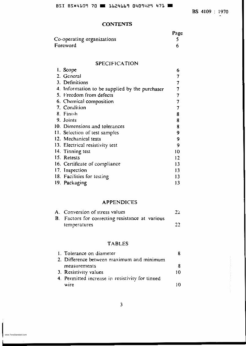
CONTENTS
Co-operating organizations Foreword
SPECIFICATION 1. Scape 2. Gencral 3. Definitions 4. Inforniation to be supplied by the purchaser 5. b'rccdom from defects 6. Cheiiiical composition 7. Contliiion 8. Finihfi 9. Joints
10. Dimensions and tolerances 11 . Selcctioii of test samples 12. Mechanical tests 13. Electrical resistivity test 14. Tinning test 15. Retests 16. Certificate of coinpliance 17. Inspection 18. Facilities for testing 19. Packaging
APPENDICES
A. Conversion of stress values B. Factors for correcting resistance at various
temperat ures
TABLES
1 . Tolerance on diameter 2. Difference between maximum rind minimum
measurements 3. Resistivity values 4. Permitted increase in resistivity for tinned
wire
3
BS 4109 : 1970
Page 5 6
6 7 7 7 7 7 7 8 8 8 9 9 9
10 12 13 13 13 13
22
22
8
8 10
10
www.TeraStandard.com
--`,`````,``````,,`,`,,,,`,,``,`-`-`,,`,,`,`,,`---
B S I B S J 4 1 0 9 7 0 1b2Ybb9 0 4 0 9 4 3 0 193
BS 4109 : 1970
Page I I I l 14
16-17
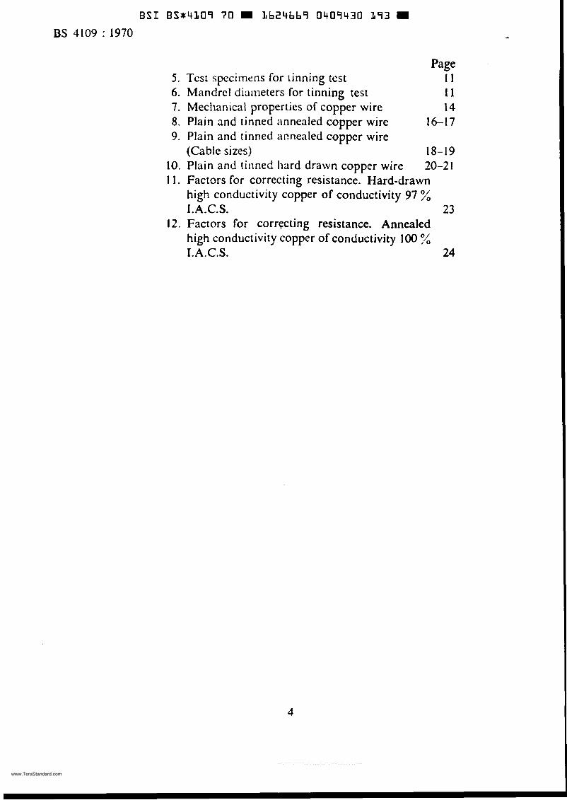
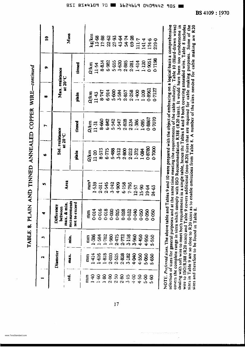
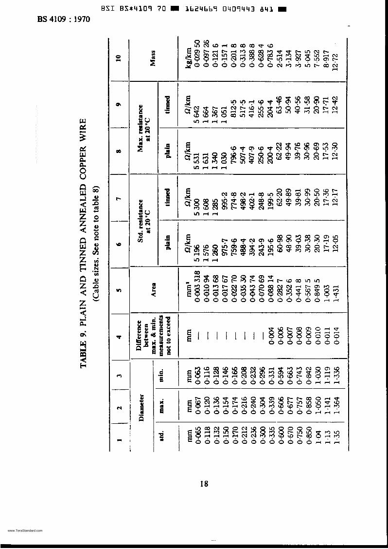
5. Tcst specimens for tinning tcst 6. Mandrcl diriineters for tinning test 7. Mechanical properties of copper wire 8. Plain and tinned annealed copper wire 9. Plain and tinned armealed copper wire
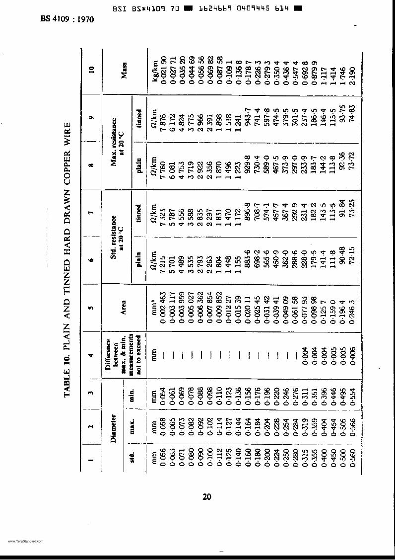
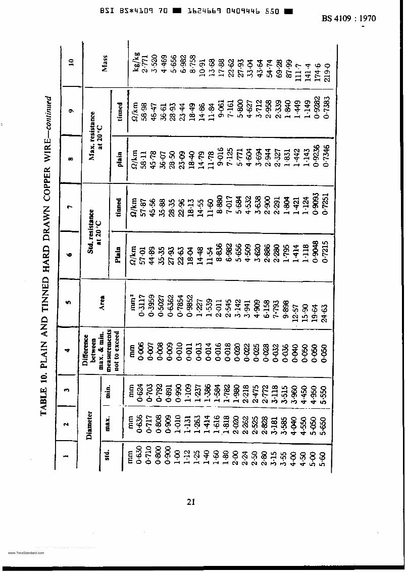
(Cable sizes) 18-19 10. Plain and tiiinec! liard drawn copper wire 1 I . Factors for correcting resistance. Hard-drawn
high conductivity copper of conductivity 97 ";o I . A.C.S. 23
12. Factors for correcting resistance. Annealed high conductivity copper of conductivity 100 T.A.C.S. 24
30-21
4
www.TeraStandard.com
--`,`````,``````,,`,`,,,,`,,``,`-`-`,,`,,`,`,,`---
BSI B S X 4 l 1 0 9 70 m Lb24667 0409433 02T m
BS 4109 : i970
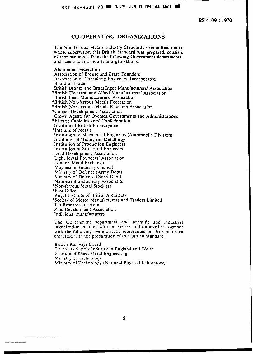
CO-OPERATING ORGANIZATIONS
The Non-ferrous Metals Industry Standards Committee, under whose supervision this British Standard was prepared, consists of representatives from the following Government departments, and scientific and industrial organizations:
Aluminium Federation Association of Bronze and Brass Founders Association of Consulting Engineers, Incorporatcd Board of Trade British Bronze and Brass Ingot Manufacturers’ Association
British Lead Manufacturers’ Association *British Electrical and Allied Manufacturers’ Association
*British Non-ferrous Metals Federation *British Non-ferrous Metals Research Association *Copper Development Association Crown Agents for Oversea Governments and Administrations
*Electric Cable Makers’ Confederation institute of British Foundryrnen
*Institute of Metals Institution of Mechanical Engineers (Automobile Division) Institutionof Miningand Metallurgy Institution of Production Engineers Institution of Structural Engineers Lead Development Association Light Metal Founders’ Association London Metal Exchange Magnesium Industry Council Ministry of Defence (Army Dept) Ministry of Defence (Navy Dept) National Brassfoundry Association
*Non-ferrous Metal Stockists Post Office
‘Society of Motor 3íanufacturers and Tradcrs Limited Royal Institute of British Architects
Tin Research Institute Zinc Development Association Individual manufacturers
The Government department and scientific and industrial organizations marked with an asterisk in the above list, íogether with the following. were directly represented on the cornmittce entrustcd wi th the preparation of this British Standard :
British Railways Board Electricity Supply Industry in England and Wales Institute of Sheet Metal Engineering Ministry of Technology Ministry of Technology (National Physical Laboratory)
5
www.TeraStandard.com
--`,`````,``````,,`,`,,,,`,,``,`-`-`,,`,,`,`,,`---
BSI BSx4109 70 L b 2 4 b b î 0409432 Tbb M
BS4109 : 1970
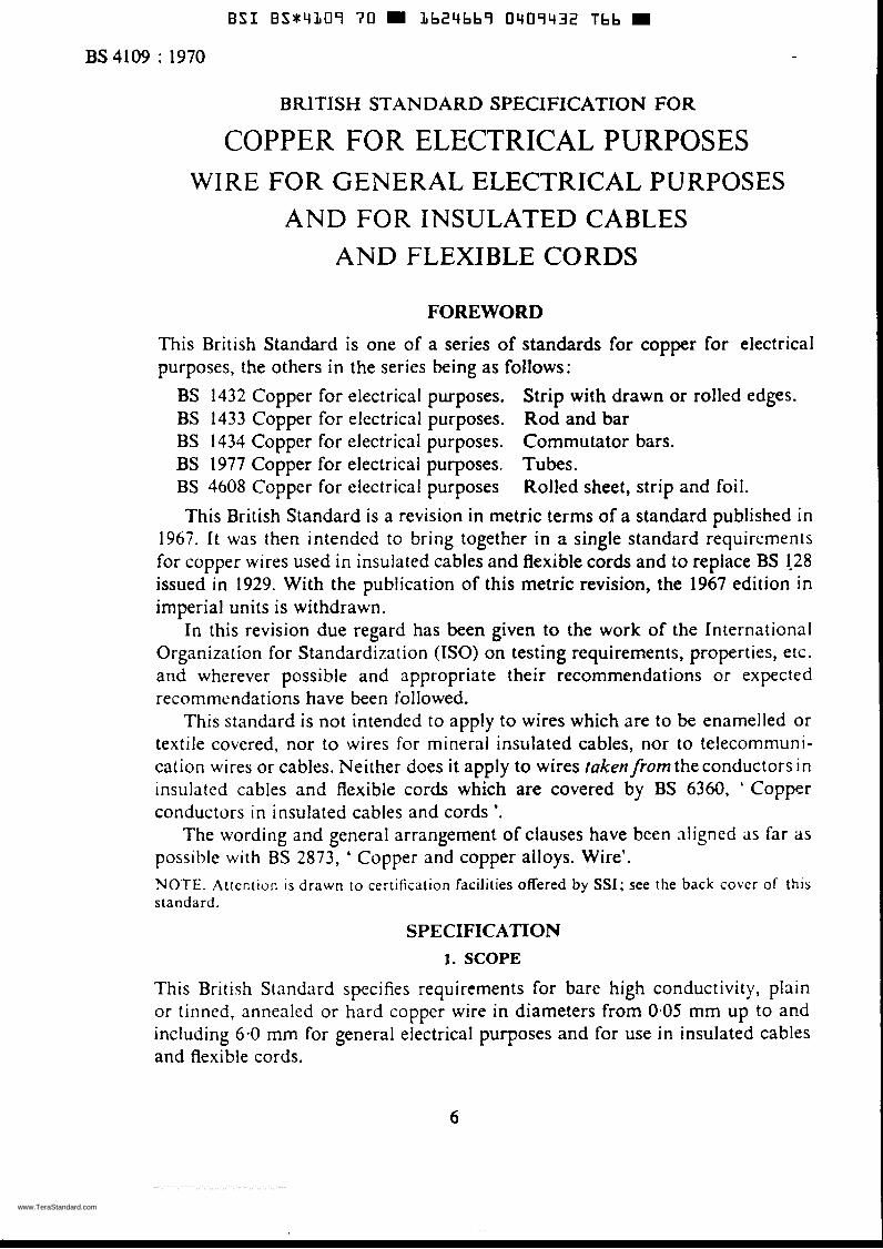
BRITISH STANDARD SPECIFICATION FOR
COPPER FOR ELECTRICAL PURPOSES WIRE FOR GENERAL ELECTRICAL PURPOSES
AND FOR INSULATED CABLES AND FLEXIBLE CORDS
FOREWORD
This British Standard is one of a series of standards for copper for electrical purposes, the others in the series being as follows:
BS 1432 Copper for electrical purposes. Strip with drawn or rolled edges. BS 1433 Copper for electrical purposes. Rod and bar BS 1434 Copper for electrical purposes. Commutator bars. BS 1977 Copper for electrical purposes. Tubes. BS 4608 Copper for electrical purposes Rolled sheet, strip and foil. This British Standard is a revision in metric terms of a standard published in
1967. it was then intended to bring together in a single standard requirements for copper wires used in insulated cables and flexible cords and to replace BS 1-28 issued in 1929. With the publication of this metric revision, the 1967 edition in imperial units is withdrawn.
In this revision due regard has been given to the work of the International Organization for Standardization (ISO) on testing requirements, properties, etc. arid wherever possible and appropriate their recommendations or expected reconimendations have been followed.
This standard is not intended to apply to wires which are to be enamelled or textile covered, nor to wires for minerai insulated cables, nor to telecommuni- cation wires or cables. Neither does it apply to wires taken from the conductors in insulated cables and flexible cords which are covered by BS 6360, ' Copper conductors in insulated cables and cords *.
The wording and general arrangement of clauses have been aligned ils far as possible with BS 2873, ' Copper and copper alloys. Wire'. NOTE. Attcntion is drawn to certification facilities offered by SSI; see the back cobcr of this standard.
SPECIFICATION 1. SCOPE
This British Standard specifies requirements for bare high conductivity, plain or tinned, annealed or hard copper wire in diameters from 0.05 rnm up to and including 6.0 mm for general electrical purposes and for use in insulated cables and flexible cords.
6
www.TeraStandard.com
--`,`````,``````,,`,`,,,,`,,``,`-`-`,,`,,`,`,,`---
E S 1 B S t 4 l 1 0 9 70 L b 2 4 b b î 0409433 9T2 W BS 4109 : 1970 -
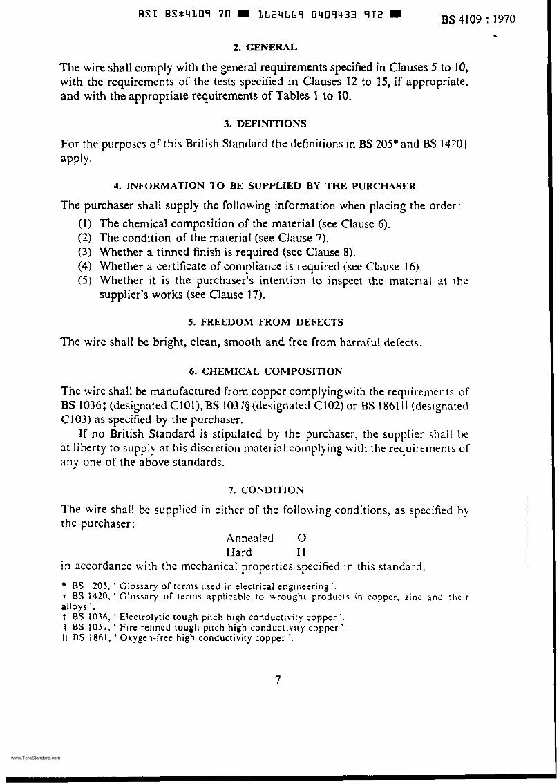
2. GENERAL
The wire shall comply with the general requirements specified in Clauses 5 to 10, with the requirements of the tests specified in Clauses 12 to 15, if appropriate, and with the appropriate requirements of Tables 1 to 10.
3. DEFINITIONS
For the purposes of this British Standard the definitions in BS 205* and BS 1420t aPP'Y-
4. INFORMATION TO BE SUPPLIED BY THE PURCHASER
The purchaser shall supply the following information when placing the order: (1) The chemical composition of the material (see Clause 6). (2) The condition of the material (see Clause 7). (3) Whether a tinned finish is required (see Clause 8). (4) Whether a certificate of compliance is required (see Clause 16). ( 5 ) Whether it is the purchaser's intention to inspect the material at the
supplier's works (see Clause 17).
5. FREEDOM FROM DEFECTS
The wire shall be bright, clean, smooth and free from harmful cieíects.
6. CHEMICAL COMPOSITION
The wire shall be manufactured from copper complyingwith the requirenients of BS 10361 (designated CIOl), BS 10379 (designated C102) or BS 1861 I I (designated C103) as specified by the purchaser.
If no British Standard is stipulated by the purchaser, the supplier shall be at liberty to supply at his discretion material complying with the requirements of any one of the above standards.
7. CONDITION
The wire shall be supplied in either of the following conditions, as specified by the purchaser:
Annealed O Hard H
in accordance with the mechanical properties specified in this standard.
ß S 205, ' Glossary of tcrnis used i n electrical engiiieering '. t BS 142U, ' Glossary of terms applicable to wrought products in copper, z inc and their alloys '. : BS 1036, ' Electrolytic tough pitch high conductivity copper '. 5 ES 1037, ' Fire refincd tough pitch high conductivity copper '. II ES 1861, ' Oxygen-free high conductivity copper '.
7
www.TeraStandard.com
--`,`````,``````,,`,`,,,,`,,``,`-`-`,,`,,`,`,,`---
BSI B S X 4 1 0 9 70 Lb24bb9 0409434 839
JTun
0-125 0.400 4-00
-
BS4109 1970
mm mm 0.125 f 0.002 0.400 f 0.004 4.00 - f 0.05
& 1 P/, of standard diameter
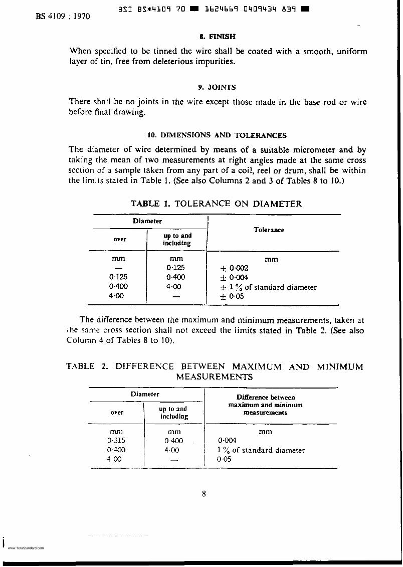
- 8. FINISH
Diameter
up to and over 1 including
When specified to be tinned the wire shall be coated with a smooth, uniform layer of tin, free from deleterious impurities.
Difíèrence between maximum and mininium
measurements
9. JOINTS
mnl 0.315 0.400 4.00
There shall be no joints in the wire except those made in the base rod or wire before final drawing.
m mm 0.400 . 0.004 4 4 0 1'4 of standard diameter - 0.05
10. DIMENSIO'NS A N D TOLERANCES
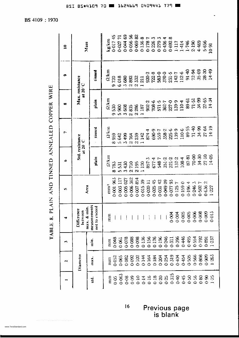
The diameter of wire determined by means of a suitable micrometer and by taking the mean of two measurements at right angles made at the same cross scction of a sample taken from any part of a coil, reel or drum, shall be within the limits stated in Table 1. (See also Columns 2 and 3 of Tables 8 to 10.)
TABLE 1. TOLERANCE ON DIAMETER
Tolerance Diameter
up to and including over I
The difference between the maximum and minimum measurements, taken at rhe same cross section shall not exceed the limits stated in Table 2. (See also Column 4 of Tables 8 to 10).
T.ABLE 2. DIFFERENCE BETWEEN MAXIMUM AND MINIM'UM MEASUREMENTS
8
www.TeraStandard.com
--`,`````,``````,,`,`,,,,`,,``,`-`-`,,`,,`,`,,`---

ES4109 :-I970
I l . SELECTION OF TEST SAMPLES
When tests are specifically called for by the purchaser the selection of test samples and the number of tests to be niade shall be agreed between the supplier arid the purchaser.
12. MECHANICAL TESTS
The following tests shall be made on test pieces selected as specified in Clause 1 1 . The mechanical properties shall comply with the appropriatc requirements
of Table 7.
12.1 Tensile test. This test applies only to wire in the H condition and shall be made in accordance with the methods described in BS i 8 Part 1'. The load shall be applied gradually and uniformly.
12.2 Elongation test. This test applies only to wire in the O condition and shall be niade in accordance with the methods described in BS 18 Part l*. The load shall be applied gradually and uniformlv to a straightened length of wire, having an original gauge length of 200 mni. Alternatively a gauge length of 250 mm may be used. The elongation shail be measured on the gauge length after the fractured ends have been fitted together. The determination shall be valid, whateLw- the position of the fracture, i f the specified value is reached. If thc specified value is not reached, the determination shall be valid only i f the fracture occurs between the gauge marks and not closcr than 25 mni to either mark.
12.3 jf'rapping test. This test applies only to Liire in the H condition. The wire sliall be wrapycd round a wirc of its own diameter to form a close hclix of cight turns. Six turns shall then be unwrapped and again closely re-wrapped in the same direction as the first wrapping. To coiiiply with the requirements of the t e j t ihc \ t i r e shall not break \\hen thus tested.
13. ELECTRICAL RESISI I\'¡ ïk' TEST
The resistivitj shall be determined by direct measurement on the wirc i n accord- ance ~ i i t h the,rqutine method given in BS 3239t.
The values obtained using the Lictors given in Tables 1 1 and 12 in Appendix B as appropriate shall not excced thc Lalues giien in Table 3, except that for tinricd v+ire in the O Lind H conditions increases in resistivity its sho\\n in Table 4 shall be permitted.
BS I R . ' Mcthods for tcniile testing of rneials ' Part 1 . Non-ferrous metal5. t ils 7 2 3 9 , * Determination of rcs is~i t of nic îa l l ic electric;il coiiductor materials '.
9
www.TeraStandard.com
--`,`````,``````,,`,`,,,,`,,``,`-`-`,,`,,`,`,,`---
BS4109 : 1970
Condition
O
B S I B S t 4 L O S 70 m Lb24669 0409436 601 m
Resistivity at 20 "C max. Conductivity*
microhm metre % 0.017 241 100
-
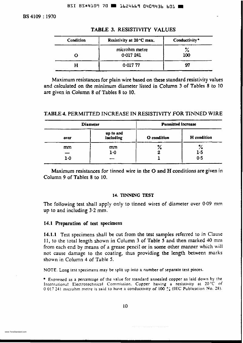
TABLE 3. RESISTIVITY VALUES
over
rn - 1.0
up to and including O condition H condition
m % % 1 -o 2 1.5 - 1 0-5
0.017 77 I 97 H I Maximum resistances for plain wire based on these standard resistivity values
and calculated on the minimum diameter listed in Column 3 of Tables 8 to i0 are given in Column 8 of Tables 8 to 10.
TABLE 4. PERMITïED INCREASE IN RESISTIVITY FOR TINNED WIRE
Diameter I Permitted increase!
Maximum resistances for tinned wire in the O and H conditions are given in Column 9 of Tables 8 to 10.
14. TINNING TEST
The following test shall apply only to tinned wires of diameter over 0.09 mm up to and including 3-2 mm.
14.1 Preparation of test specimens
14.1.1 Test specimens shall be cut from the test samples referred to in Clause 11 , to the total length shown in Column 3 of Table 5 and then marked 40 mni from each end by means of a grease pencil or in some other manner which will not cause damage to the coating, thus providing the length between marks shown in Column 4 of Table 5 .
NOTE. Long test specimens may be split up into a number of separate test pieces.
Expresscd as a percentage of the value for standard annealed copper as laid down by the International Electrorechnical Commission. Copper having a resistivity a t 20 ' C of O 017 241 microhm nietre is said to have a conductivity of 100 :i (IEC Publication NO. 2 8 ) .
10
www.TeraStandard.com
--`,`````,``````,,`,`,,,,`,,``,`-`-`,,`,,`,`,,`---
B S I B S * 4 1 0 9 70 L b 2 4 b b ï 0 4 0 9 4 3 7 5 4 8
2 I 1
Diameter
ES 4109 f 1970
4 3
Length of test specimen 1
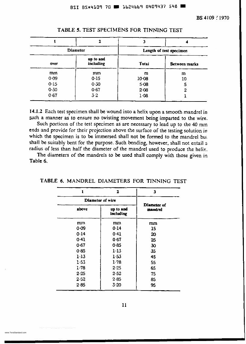
TABLE 5. TEST SPECIMENS FOR TINNING TEST
I
mm mm 0.09 0-15 0.15 0.30 0.30 0.67 0.67 3.2
m m 10.08 10 5-08 5 2.08 2 1-08 1
Between marks over l including I Total I up to and
14.1.2 Each test specimen shall be wound into a helix upon a smooth mandrel in such a manner as to ensure no twisting movement being imparted to the wire.
Such portions of the test specimen as are necessary to lead up to the 40 mm ends and provide for their projection above the surface of the testing soIution in which the specimen is to be immersed shall not be formed to the mandrel bu: shall be suitably bent for the purpose. Such bending, however, shall not entail û
radius of less than half the diameter of the mandrel used to produce the helix. The diameters of the mandrels to be used shall comply with those given in
Table 6.
TABLE 6. MANDREL DIAMETERS FOR TINNING TEST
1 2 ~~
Diameter of wire
above
mm 0.09 0.14 0.41 0-67 0.85 1-13 1.53
2.25 2 -52 2-85
1-78
up to lad inciuding
mm 0.14 0.41 0.67 0-85 1.13 1-53 1.78 2.25 2.52 2-85 3-20
3
Diomettr of IMIBdItl
mm 15 20 25 30 35 45 55 65 75 05 95
www.TeraStandard.com
--`,`````,``````,,`,`,,,,`,,``,`-`-`,,`,,`,`,,`---
B S I B S J 4 1 0 9 70 1624669 0409438 484
BS4109 : 1970 -
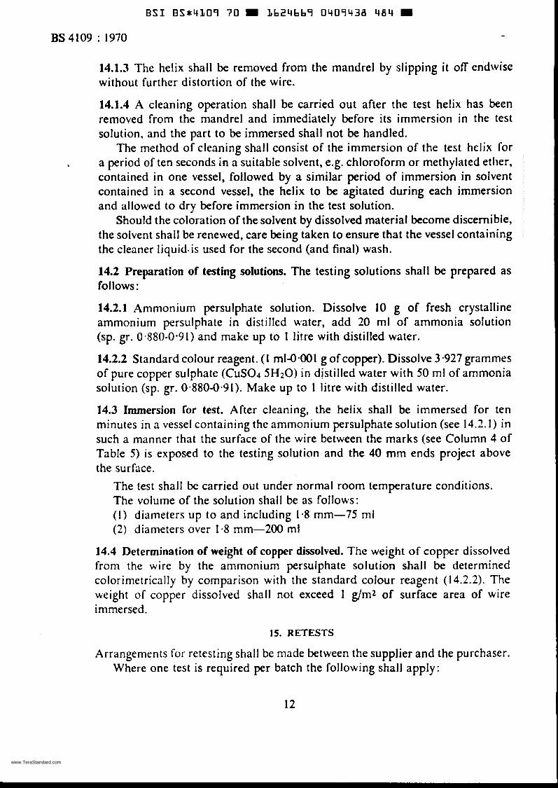
14.1.3 The helix shall be removed from the mandrel by slipping i t off endwise without further distortion of the wire.
14.1.4 A cleaning operation shall be carried out after the test helix has been removed from the mandrel and immediately before its immersion in the test solution, and the part to be immersed shall not be handled.
The method of cleaning shall consist of the immersion of the test helix for a period of ten seconds in a suitable solvent, e.g. chloroform or methylated ether, contained in one vessel, followed by a similar period of immersion in solvent contained in a second vessel, the helix to be agitated during each immersion and allowed to dry before immersion in the test solution.
Should the coloration of the solvent by dissolved material become discernible, the solvent shall be renewed, care being taken to ensure that the vessel containing the cleaner liquids is used for the second (and final) wash.
14.2 Preparation of testing solutions. The testing solutions shall be prepared as fo 1 I ows :
14.2.1 Ammonium persulphate soIution. Dissolve 10 g of fresh crystalline ammonium persulphate in distilled water, add 20 ml of ammonia solution (sp. gr. 0.880-0.91) and make up to 1 l h e with distilled water.
14.2.2 Standard colour reagent. ( I ml-0.001 g of copper). Dissolve 3-927 grammes of pure copper sulphate (CuSO4 5H20) in distilled water with 50 ml of ammonia solution (sp. gr. 0.880-0.91). Make up to 1 litre with distilled water.
14.3 Immersion for test. After cleaning, the helix shall be immersed for ten minutes in a vessel containing the ammonium persulphate solution (see 14.2. I ) in such a manner that the surface of the wire between the marks (see Column 4 of Table 5 ) is exposed to the testing solution and the 40 mm ends project above the surface.
The test shall bc carried out under normal room temperature conditions. The volume of the solution shall be as follow~s: ( 1 ) diameters up to and including 1.8 mm-75 ml (2) diameters over 1.8 mm-200 ml
14.4 Determination of weight of copper dissolved. The weight of copper dissolved from the wire by the ammonium persulphate solution shall be determined colorimetrically by comparison with the standard colour reagent (14.2.2). The weight of copper dissolved shall not exceed 1 g/m2 of surface area of wire immersed.
15. RETESTS
Arrangements for retesting shall be made between the supplier and the purchaser. Where one test is required per batch the following shall apply:
12
www.TeraStandard.com
--`,`````,``````,,`,`,,,,`,,``,`-`-`,,`,,`,`,,`---
E S 1 BS*41Oï 70 1624669 0409439 310
n . u..ou
BS 4109 : 1970
i any orte of the test pieces first seiected fail to pass any of the prescribed tests, two further samples from the same batch shall be selected for testing, one of which shall be from the piece from which the original test sample was taken unless that piece has been withdrawn by the supplier.
Should the test pieces from both these additional samples pass, the batch represented by the test samples shall be deemed to comply with this standard. Should the test pieces from either of these additional samples fail, the batch represented by the test samples shall be deemed not to comply with this standard.
16. CERTIFICATE OF COMPLIANCE
The supplier shall, if required, certify that the material complies with the rcquire- ments of this standard appropriate to the material ordered.
17. INSPECTION
The purchaser shall notify the supplier when placing the order i f i t is his intention to inspect the material at the supplier's works. The supplier shall afford the purchaser all reasonable fiicilities to satisfy himself that the material is in accordance with this standard. For this purpose the purchaser or his representa- tive may by prior arrangement attend to inspect the material, to select and identify the test sample for testing and to witness the tests being made.
The purchaser shall be at liberty to take simples from the material seiected in accordance with Clause I l and have them anaiysed. The cost of such analysis shall be borne by the purchaser and the results shall be communicated to the supplier i f they are not in accordance with the requirements specified in Clause 6 .
1%. FACILITIES FOR TESTING
The supplier shall provide and prepare the necessary test pieces, and supply labour and appliance for such testing as may be carried out on his premises ¡ti
accordance with this standard. Unless otherwise agreed, material for testing shall remain the property of the supplier. Failing facilities at his own works for making the prescribed tests, the supplier shall make thc necessary arrangements for mak- ing the tests elsewhere.
19. PACKAGING
The method of packaging shall be specified by the purchaser.
coils shall be the subject of agreement between the supplier and the purchaser. When the wire is supplied in coils, the eye diameter and the weight of the
13
www.TeraStandard.com
--`,`````,``````,,`,`,,,,`,,``,`-`-`,,`,,`,`,,`---
BSI B S X 4 L O 9 7 0 m Lb24bb9 0409440 032
Condition
- BS4109 : 1970
~
Diameter Tensile Elongation strength min. min.
up to over and Plain Tinned Plain
including wire wire wire
mm mm hbart hbart % - 1-60 45.6 40.9 - 1.60 2.50 44.6 40.2 - 2.50 3.15 43-7 39.4 - 3.15 3.55 42.9 38.6 - 3.55 4.0 42.2 38.0 4.0 5.0 41.2 37.1 - 5.0 5-6 40.6 36-6 -
- 10 - 15 - 20 - 25 - 30
- 0.14 - 0.14 0-21 - 0.21 0-51 - 0.51 1.36 - 1.36 - -
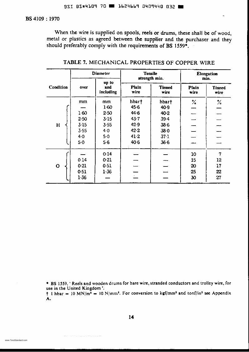
When the wire is supplied on spools, reels or drums, these shall be of wood, metal or plastics as agreed between the supplier and the purchaser and they should preferably comply with the requirements of BS 1559*.
TABLE 7. MECHANICAL PROPERTIES OF COPPER WIRE
Tinned wire
BS 1559, ' Reels and wooden drums for bare wire, stranded conductors and trolley wire, for use in the United Kingdom '. t 1 hbar = 10 MN/m' - 10 N/mm'. For conversion to kgf/mma and tonf/in'see Appendix A.
14
www.TeraStandard.com
--`,`````,``````,,`,`,,,,`,,``,`-`-`,,`,,`,`,,`---
B S I B S * 4 3 O î 70 1624bb î O409443 T i 9 W
BS 4109 : 1970
9
v) 111 (rl
ir
CI .- i 'i
l 6 Previous page is blank
www.TeraStandard.com
--`,`````,``````,,`,`,,,,`,,``,`-`-`,,`,,`,`,,`---
BSI BS*4L09 70 9 Lb24bb9 0409442 905 m
.--- E N O I
BS4109 : 1970 -
17
www.TeraStandard.com
--`,`````,``````,,`,`,,,,`,,``,`-`-`,,`,,`,`,,`---
B S I B S * 4 1 0 9 70 m 1624669 0409443 841 m BS4109 : 1970
n 00
O .c,
. - .CI cn
o,
n
rn
--
CI
I
!! 5Y Ea a
18
www.TeraStandard.com
--`,`````,``````,,`,`,,,,`,,``,`-`-`,,`,,`,`,,`---

B S I B S X 4 l O ï 70 l b 2 4 b b ï 0407444 788 W
I E
BS 4109 : 1970
I I
I
1 " i i
19
www.TeraStandard.com
--`,`````,``````,,`,`,,,,`,,``,`-`-`,,`,,`,`,,`---
BSI B S t 4 1 0 9 7 0 = Lh24hb9 0409445 bL4 BS4109 : 1970
e
P
- a I
-
20
www.TeraStandard.com
--`,`````,``````,,`,`,,,,`,,``,`-`-`,,`,,`,`,,`---
BSI B S * 4 L 0 9 70 = II624669 0409446 550 BS4109 : 1970
d r l d c u I
21
www.TeraStandard.com
--`,`````,``````,,`,`,,,,`,,``,`-`-`,,`,,`,`,,`---
BSI BS*4LOï 7 0 m L b 2 4 b b î 0409447 497 m BS4109 : 1970
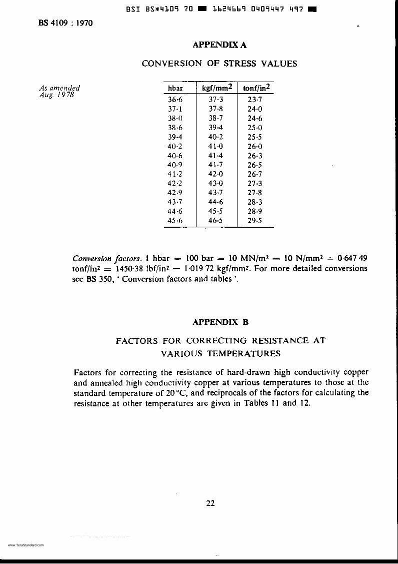
kgfimm2 37.3 37.8 38.7 39.4 40.2 4 1-0 41.4 41.7 42.0 43.0 43.7 44.6 45.5 46.5
As ametided Aug. I9 78
tonf/in2 23-7 24.0 24-6 25 -0 25 -5 26.0 26-3 26.5 26.7 27.3 27.8 28.3 28.9 29-5
APPENDIX A
CONVERSION OF STRESS VALUES
hbar -
36.6 37- 1 38.0 38.6 39-4 40-2 40-6 40.9 4 1.2 42.2 42.9 43.7 44.6 45.6
Conversion factors. 1 hbar = 100 bar = 10 MN/m2 = 10 N/mm2 = 0.647 49 tonflin2 = 1450.38 lbf/inz = 1-019 72 kgf/rnm2. For more detailed conversions see BS 350, ' Conversion factors and tabies '.
APPENDIX B
FACTORS FOU CORRECTING RESISTANCE AT VARIOUS TEMPERATURES
Factors for correcting the resistance of hard-drawn high conductivity copper and annealed high conductivity copper at various temperatures to those at the standard temperature of 20 O C , and reciprocals of the factors for calculating the resistance at other temperatures are given in Tables 1 1 and 12.
22
www.TeraStandard.com
--`,`````,``````,,`,`,,,,`,,``,`-`-`,,`,,`,`,,`---
B S I B S * 4 L O 9 70 m 3 6 2 4 b b 9 0 4 0 9 4 4 8 323 m BS4109 : I970
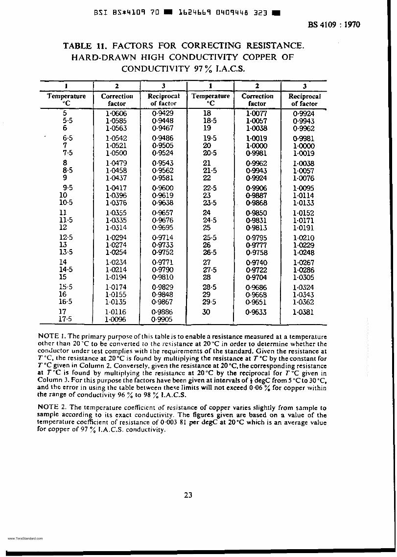
TABLE 11. FACTORS FOR CORRECTING RESISTANCE. HARD-DRAWN HIGH CONDUCTIVITY COPPER OF
CONDUCTIVITY 97 % I.A.C.S.
1 Tcmpcrature
"C 5 5.5 6 6.5 7 7.5 8 8.5 9 9.5 10 10.5 11 11.5 12 12.5 13 13.5 14 14.5 15 15-5 16 16.5 17 17.5
2 Correctioii
factor 1.0606 1.0585 1.0563 1.0542 1.0521 1.0500 1-0479 1.0458 1-0437 1.0417 1.0396 1.0376 1-0355 1.0335 1.0314 1.0294 1.0274 1.0254 1.0234 1.0214 1.0194 1.0174 1.0155 1.0135 1.0116 1.0096
Rcciprocal of facror
0-9429 0-9448 0.9467 0-9486 0.9505 0.9524 0.9543 0.9562 0.9581 0*9600 0-9619 0.9638 0-9657 0-9676 0.9695 0-9714 0-9733 0-9752 0.977 1 0-9790
0.0829 0.9848 0.9867 0.9886 0.9905
0;9810
~~
1 Tempera ture
"C 18 18-5 19 19-5 20 20-5 21 21-5 22 22.5 23 23-5 24 24.5 25 25.5 26 26.5 27 27.5 28 28.5 29 29.5 30
~
2 Correct ion
factor 1.0077 1.0057 1.0038 1.0019 1-oooO 0.9981 0.9962 0.9943 04924 0.9906 0.9887 0.9868 0.9850 0-9831 0-9813 0.9795 0-9777 0-9758 0.9740 0.9722 0.9704 0.9686 0.9668 0.9651 0-9633
3 Reciproca I of factor 0-9924 0.9943 0.9962 0.9981 l9oooO 1.0019 1.0038 1.0057 1.0076 1.0095 1-0114 1-0133 1.0152 1.0171 1.0191 1.0210 1.0229 1.0248 1.0267 1-0286 1.0305 1.0324 1.0343 1.0362 1.0381
NOTE I . The primary purpose of this table is to enable a resistance measured at a temperature othcr than 20'C to be converted to thc resistance at 20°C in order to determine whether the conductor under test complies with flie requirerncnts of the standard. Givcn Che resistance at TOC, the resistance at 20°C is found by miiitiplying the resistance at T T by theconstant for T "C given in Column 2. Conversely. given the resistance at 20"C,the corresponding resistance at T"C is found by multiplying the resistance at 20°C by the reciprocal for TOC given in Column 3. For this purpose the factors have been given at intervals of degC from 5 "Cto 30'C, and the error in using the table between these limits will not exceed 0.06 % for copper within the range of conductivity 96 % to 98 % I.A.C.S.
NOTE 2. The temperature coefficient of resistance of copper varies slightly from sample to sample according to its exact conductivity. The figures given are based on a value of the temperature coefficient of resistance of 0.003 81 per degC at 20°C which is an average value for copper of 97 % I.A.C.S. conductivity.
23
www.TeraStandard.com
--`,`````,``````,,`,`,,,,`,,``,`-`-`,,`,,`,`,,`---
E S 1 BS*4L09 70 1624669 0409449 2bT
BS4109 : 1970
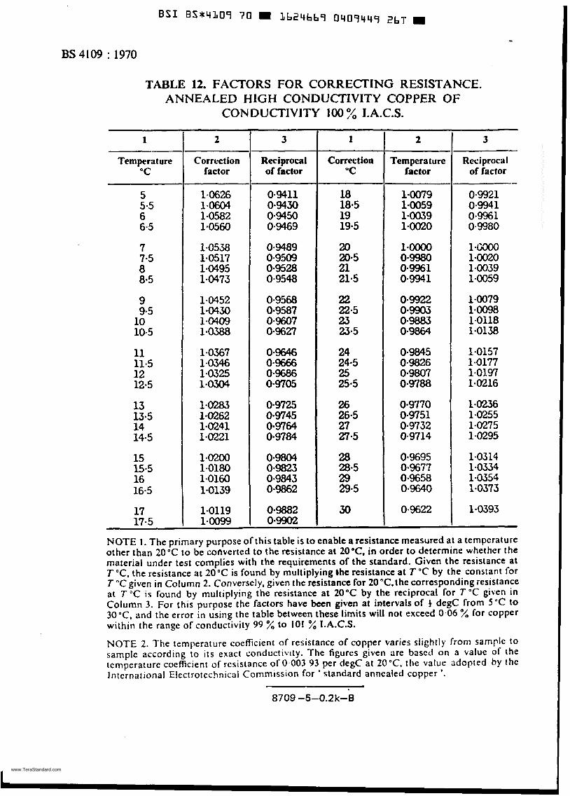
TABLE 12. FACTORS FOR CORRECTING RESISTANCE. ANNEALED HIGH CONDUCTIVITY COPPER OF
CONDUCTIVITY 100 :/o I.A.C.S.
1
Temperature "C
5 5.5 6 6.5
7 7.5 a 8.5
9 9.5 10 10.5
11 11.5 12 12.5
13 13.5 14 14.5
15 15.5 16 16.5
17 17.5
2
Correction factor
1.0626 1.0604 1.0582 1.0560
1.0538 1.0517 1.0495 1.0473
1.0452 1.0430 1.0409 1.0388
1-0367 1.0346 1.0325 1.0304
1.0283 1.0262 1.0241 1.0221
1.02oO 1.0180 1.0160 1.0139
1.0119 1.0099
3
Reciprocal of factor
0.9411 0.9430 0.9450 0.9469
0.9489 0.9509 0.9528 0.9548
0.9568 0.9587 0.9607 0.9627
0.9&?6 0.9666 0.9686 0.9705
0.9725 0.9745 0.9764 0.9784
0.9804 0.9823 0.9843 0.9862
0.9882 0-9902
1
Correction 'C
~
18 18.5 19 19.5
20 20.5 21 21.5
22 22.5 23 23.5
24 24.5 25 25.5
26 26.5 27 27.5
28 28.5 29 29.5
30
2 ~~
Tempera turc factor
1-0079 1.0059 1.0039 1.0020
1.ooOO 0.9980 0.9961 0.9941
0922 0.9903 0.9883 0.9864
0.9845 0-9826 0.9807 0.9788
0-9770 0.9751 0.9732 0-9714
0.9695 0.9677 0.9658 0.9640
0.9622
3
Reciprocal of factor
0.9921 0.994 1 0.9961 0.9980
1.('/300 1-0020 1.0039 1.0059
1-0079 1.0098 1-0118 1.0138
1.0157 1.0177 1.0197 1.0216
1.0236 1.0255 1-0275 1.0295
1.0314 1.0334 1.0354 1.0373
1.0393
-
NOTE 1. The primary purpose of this table is to cnable a resistance measured at a ternpcrature other than 20°C to be converted to the resistance at 20°C. in order to determine whether the material under test complies with the requirements of the standard. Given the resistance at T "C. the resistance at 20°C is found by multiplying Che resistance at T "C by the constant for T "C given in Column 2. Converscly. given the resistance for 2O"C,the corresponding resistance at T "C is found by multiplying the resistance at 20°C by the reciprocal for T "C given in Column 3. For this purpose the factors have been given at intervals of degC from 5 "C to 30°C. and the error in using the table between these limits will not exceed 0.06 % for copper within the range of conductivity 99 % to i01 % I.A.C.S.
NOTE 2. The temperature coefficient of resistance of copper varies slightly from sample 10 sample according to its exact conductivity. The figures given are based on a value of the ternperaturc coefficient of resisíance of 0.003 93 per degC at 20°C. the value adopted by thc International Electrotcchnical Commission for ' slandard annealed copper '.
8709 -5-0.2k-8
c
www.TeraStandard.com
--`,`````,``````,,`,`,,,,`,,``,`-`-`,,`,,`,`,,`---