fnal-pxie hwr: electromagnetic design · fnal-pxie hwr: electromagnetic design b. mustapha physics...
TRANSCRIPT
FNAL-PXIE HWR: Electromagnetic Design
B. Mustapha
Physics Division, ANL
Review of FNAL-PXIE 162.5 MHz HWR Cryomodule
Argonne, March 5, 2012
B. Mustapha FNAL-PXIE HWR: EM Design Review of FNAL-PXIE HWR Cryomodule, March, 5, 2012
2
Content
The EM Design Optimization Procedure – Fully parameterized geometry
– Optimization goals
– Semi-automatic optimization using CST parameter sweeps
The Original Race-Track Geometry – Problems, Solutions & Limitations
– Final Race-Track Design
The Ring-Shaped Center Conductor Geometry – Comparison to the race-track geometry
– Significant increase in shunt impedance !?
Final HWR Design – Re-Optimization Using Tetrahedral Mesh in CST-2011
– Effect of Coupling and Processing Ports
B. Mustapha FNAL-PXIE HWR: EM Design Review of FNAL-PXIE HWR Cryomodule, March, 5, 2012
3
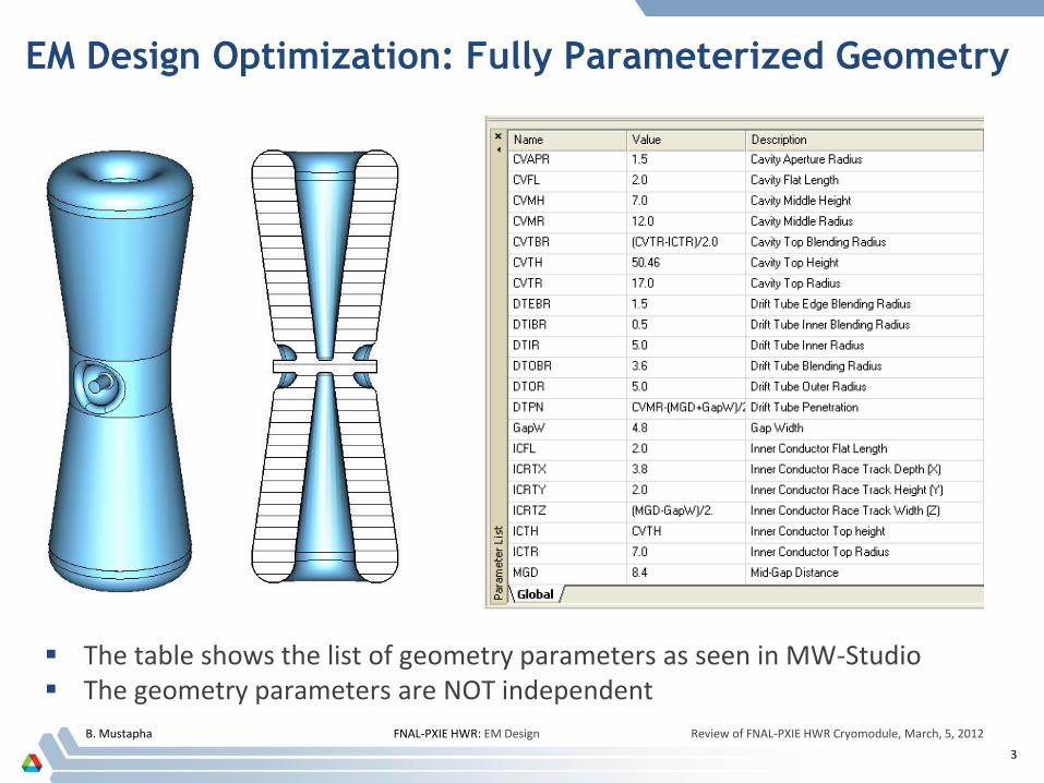
EM Design Optimization: Fully Parameterized Geometry
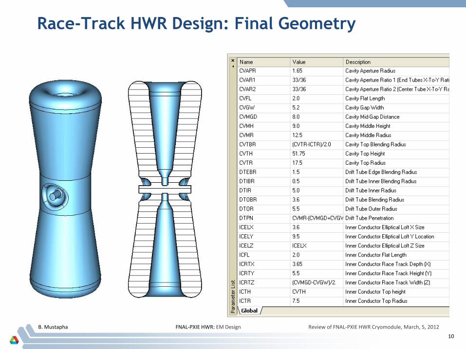
The table shows the list of geometry parameters as seen in MW-Studio The geometry parameters are NOT independent
B. Mustapha FNAL-PXIE HWR: EM Design Review of FNAL-PXIE HWR Cryomodule, March, 5, 2012
4
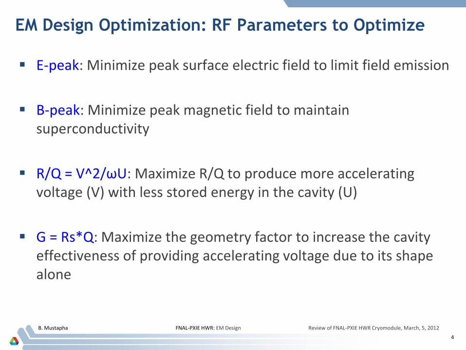
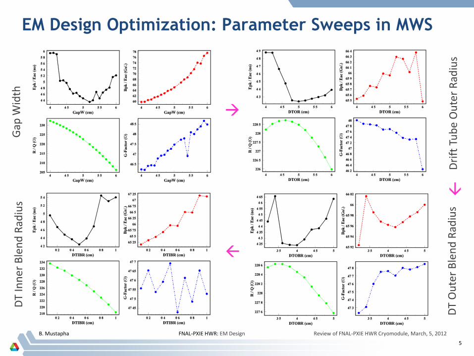
EM Design Optimization: RF Parameters to Optimize
E-peak: Minimize peak surface electric field to limit field emission
B-peak: Minimize peak magnetic field to maintain superconductivity
R/Q = V^2/ωU: Maximize R/Q to produce more accelerating voltage (V) with less stored energy in the cavity (U)
G = Rs*Q: Maximize the geometry factor to increase the cavity effectiveness of providing accelerating voltage due to its shape alone
B. Mustapha FNAL-PXIE HWR: EM Design Review of FNAL-PXIE HWR Cryomodule, March, 5, 2012
5
EM Design Optimization: Parameter Sweeps in MWS
Dri
ft T
ub
e O
ute
r R
adiu
s
DT
Inn
er
Ble
nd
Rad
ius
Gap
Wid
th
DT
Ou
ter
Ble
nd
Rad
ius
B. Mustapha FNAL-PXIE HWR: EM Design Review of FNAL-PXIE HWR Cryomodule, March, 5, 2012
6
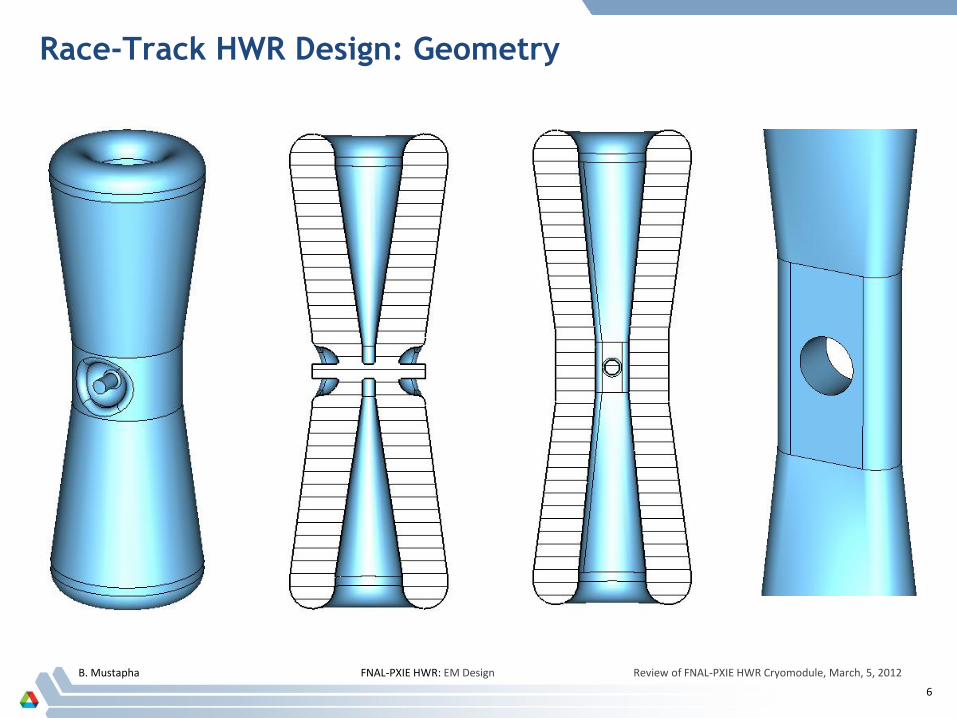
Race-Track HWR Design: Geometry
B. Mustapha FNAL-PXIE HWR: EM Design Review of FNAL-PXIE HWR Cryomodule, March, 5, 2012
7
Race-Track HWR Design: Problems, Solutions & Limitations
The race-track center conductor produces a quadrupole electric field component leading to a transverse beam asymmetry Elliptical aperture.
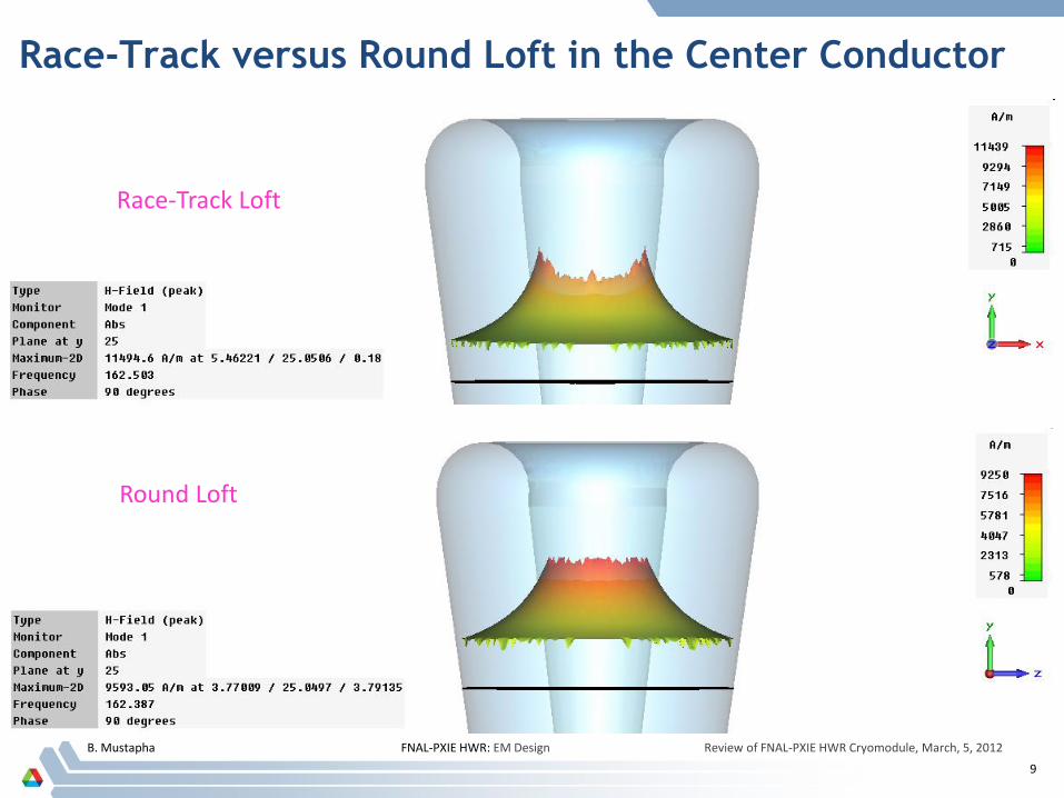
The loft from the race-track to the round cavity top results in a non uniform magnetic field around the center conductor with the highest fields in the welding areas Intermediate round loft.
The race-track geometry may be optimum for the E-peak but it is NOT optimum for the shunt impedance.
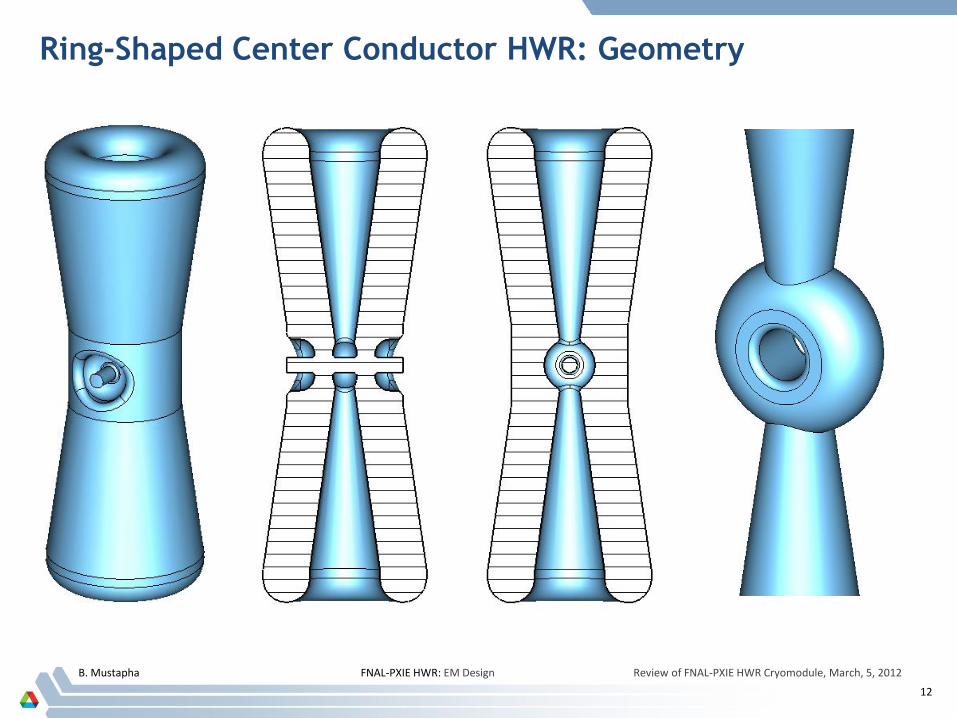
All of these problems are solved in the ring-shaped center conductor geometry.
B. Mustapha FNAL-PXIE HWR: EM Design Review of FNAL-PXIE HWR Cryomodule, March, 5, 2012
8
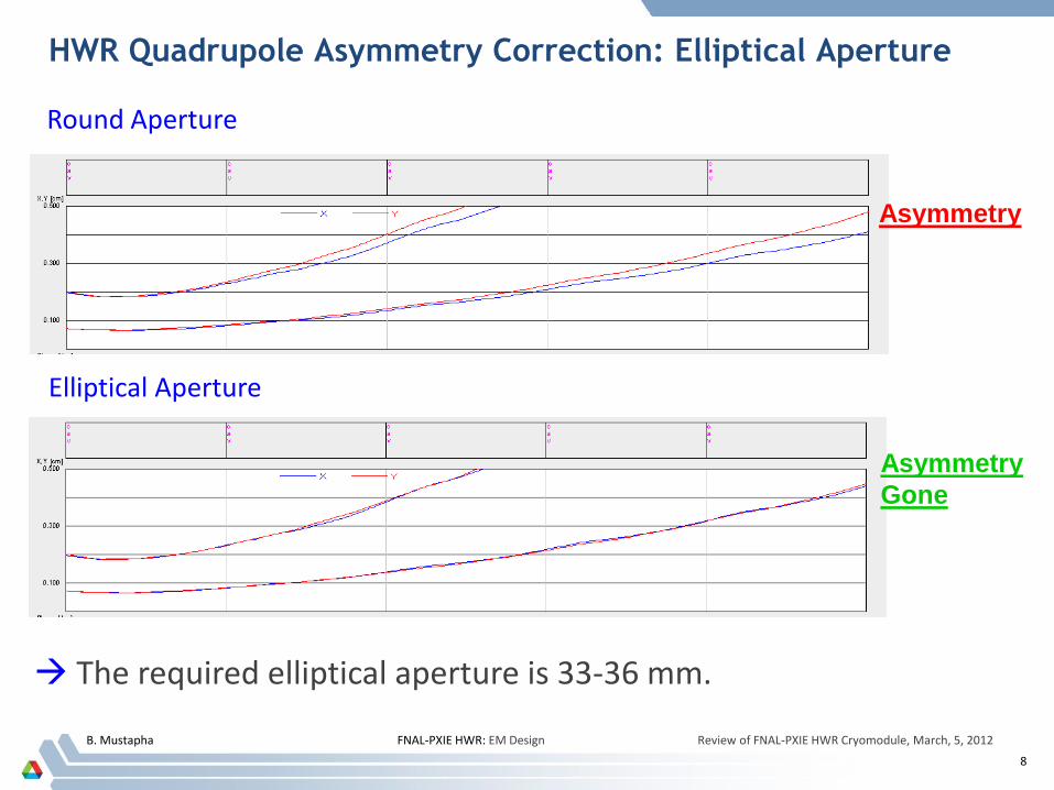
HWR Quadrupole Asymmetry Correction: Elliptical Aperture
Asymmetry
Round Aperture
Asymmetry
Gone
Elliptical Aperture
The required elliptical aperture is 33-36 mm.
B. Mustapha FNAL-PXIE HWR: EM Design Review of FNAL-PXIE HWR Cryomodule, March, 5, 2012
9
Race-Track versus Round Loft in the Center Conductor
Race-Track Loft
Round Loft
B. Mustapha FNAL-PXIE HWR: EM Design Review of FNAL-PXIE HWR Cryomodule, March, 5, 2012
10
Race-Track HWR Design: Final Geometry
B. Mustapha FNAL-PXIE HWR: EM Design Review of FNAL-PXIE HWR Cryomodule, March, 5, 2012
11
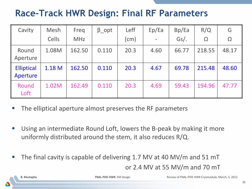
Race-Track HWR Design: Final RF Parameters
Cavity Mesh
Cells
Freq
MHz
β_opt Leff
(cm)
Ep/Ea
-
Bp/Ea
Gs/.
R/Q
Ω
G
Ω
Round Aperture
1.08M 162.50 0.110 20.3 4.60 66.77 218.55 48.17
Elliptical Aperture
1.18 M 162.50 0.110 20.3 4.67 69.78 215.48 48.60
Round Loft
1.02M 162.49 0.110 20.3 4.69 59.43 194.96 47.77
The elliptical aperture almost preserves the RF parameters
Using an intermediate Round Loft, lowers the B-peak by making it more uniformly distributed around the stem, it also reduces R/Q.
The final cavity is capable of delivering 1.7 MV at 40 MV/m and 51 mT
or 2.4 MV at 55 MV/m and 70 mT
B. Mustapha FNAL-PXIE HWR: EM Design Review of FNAL-PXIE HWR Cryomodule, March, 5, 2012
12
Ring-Shaped Center Conductor HWR: Geometry
B. Mustapha FNAL-PXIE HWR: EM Design Review of FNAL-PXIE HWR Cryomodule, March, 5, 2012
13
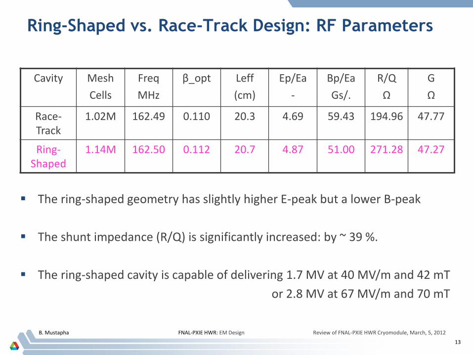
Ring-Shaped vs. Race-Track Design: RF Parameters
Cavity Mesh
Cells
Freq
MHz
β_opt Leff
(cm)
Ep/Ea
-
Bp/Ea
Gs/.
R/Q
Ω
G
Ω
Race-Track
1.02M 162.49 0.110 20.3 4.69 59.43 194.96 47.77
Ring-Shaped
1.14M 162.50 0.112 20.7 4.87 51.00 271.28 47.27
The ring-shaped geometry has slightly higher E-peak but a lower B-peak
The shunt impedance (R/Q) is significantly increased: by ~ 39 %.
The ring-shaped cavity is capable of delivering 1.7 MV at 40 MV/m and 42 mT
or 2.8 MV at 67 MV/m and 70 mT
B. Mustapha FNAL-PXIE HWR: EM Design Review of FNAL-PXIE HWR Cryomodule, March, 5, 2012
14
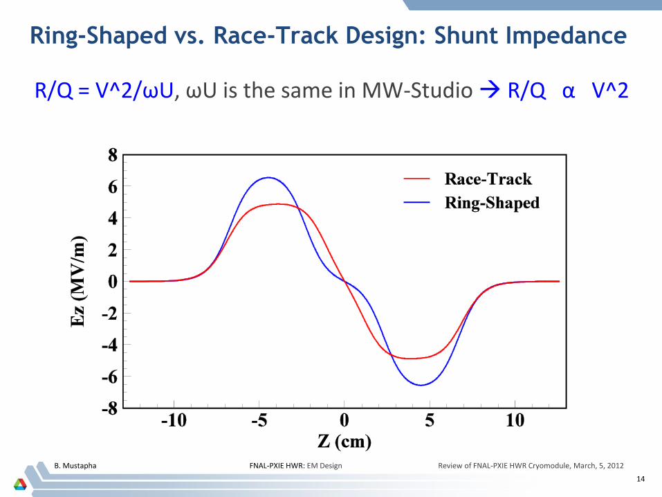
Ring-Shaped vs. Race-Track Design: Shunt Impedance
R/Q = V^2/ωU, ωU is the same in MW-Studio R/Q α V^2
B. Mustapha FNAL-PXIE HWR: EM Design Review of FNAL-PXIE HWR Cryomodule, March, 5, 2012
15
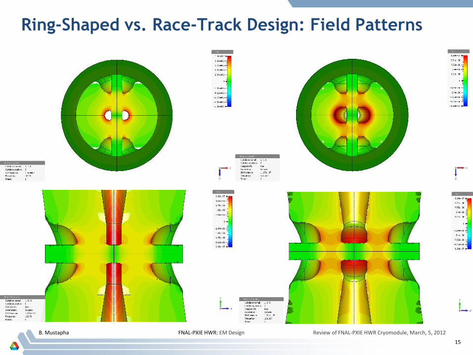
Ring-Shaped vs. Race-Track Design: Field Patterns
B. Mustapha FNAL-PXIE HWR: EM Design Review of FNAL-PXIE HWR Cryomodule, March, 5, 2012
16
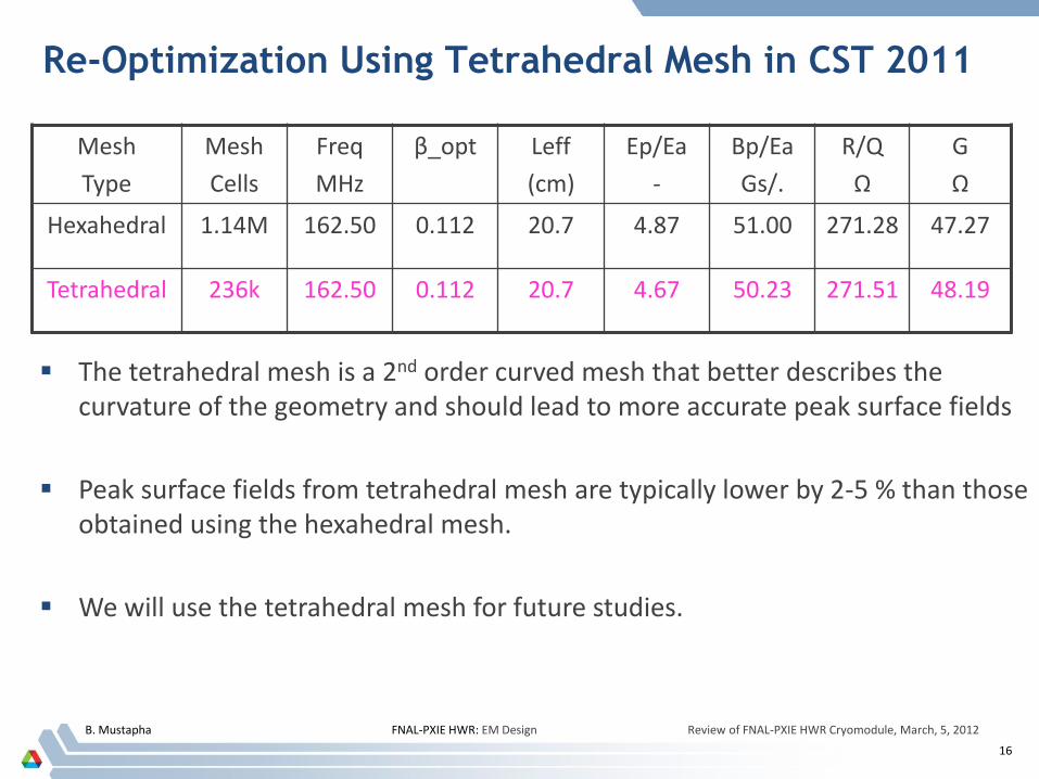
Re-Optimization Using Tetrahedral Mesh in CST 2011
Mesh
Type
Mesh
Cells
Freq
MHz
β_opt Leff
(cm)
Ep/Ea
-
Bp/Ea
Gs/.
R/Q
Ω
G
Ω
Hexahedral 1.14M 162.50 0.112 20.7 4.87 51.00 271.28 47.27
Tetrahedral 236k 162.50 0.112 20.7 4.67 50.23 271.51 48.19
The tetrahedral mesh is a 2nd order curved mesh that better describes the curvature of the geometry and should lead to more accurate peak surface fields
Peak surface fields from tetrahedral mesh are typically lower by 2-5 % than those obtained using the hexahedral mesh.
We will use the tetrahedral mesh for future studies.
B. Mustapha FNAL-PXIE HWR: EM Design Review of FNAL-PXIE HWR Cryomodule, March, 5, 2012
17
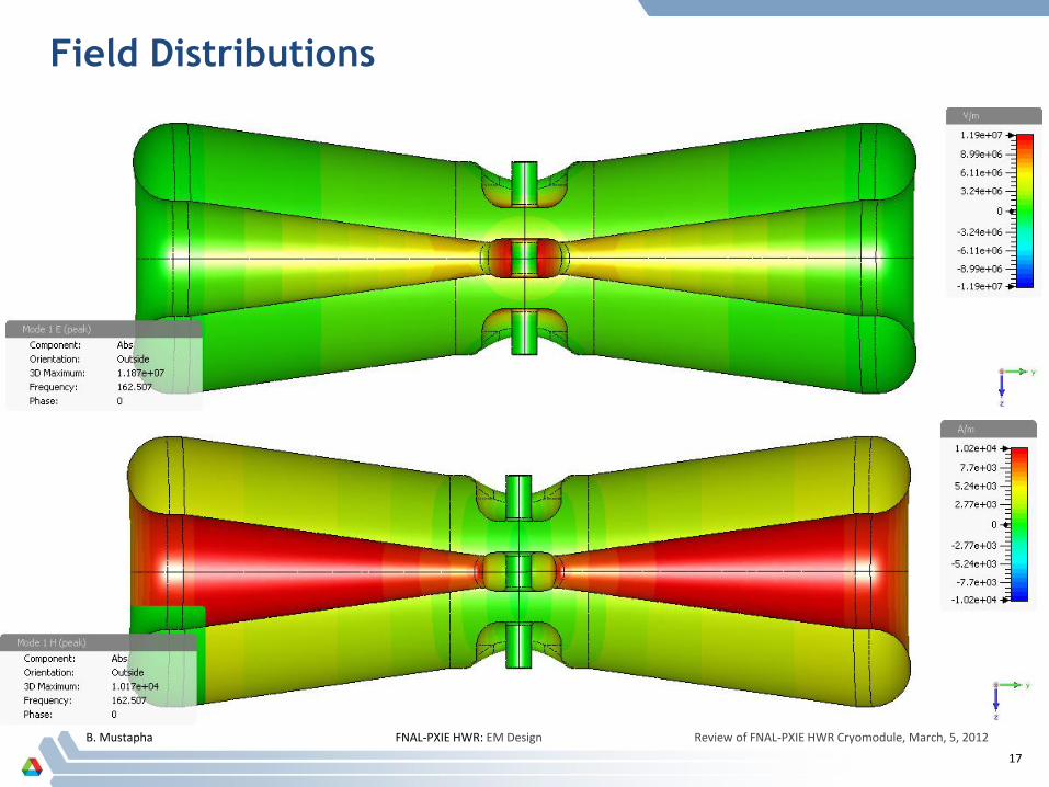
Field Distributions
B. Mustapha FNAL-PXIE HWR: EM Design Review of FNAL-PXIE HWR Cryomodule, March, 5, 2012
18
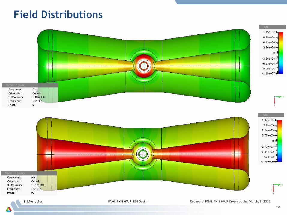
Field Distributions
B. Mustapha FNAL-PXIE HWR: EM Design Review of FNAL-PXIE HWR Cryomodule, March, 5, 2012
19
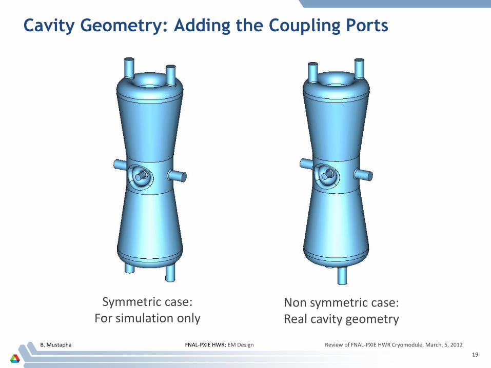
Cavity Geometry: Adding the Coupling Ports
Symmetric case: For simulation only
Non symmetric case: Real cavity geometry
B. Mustapha FNAL-PXIE HWR: EM Design Review of FNAL-PXIE HWR Cryomodule, March, 5, 2012
20
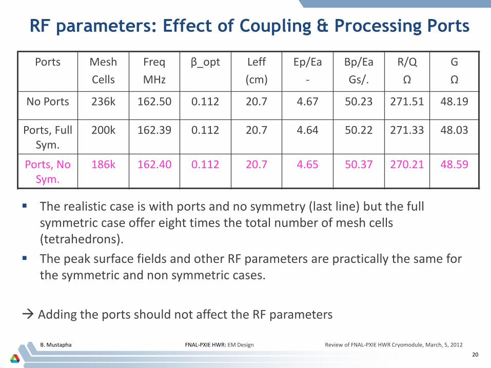
RF parameters: Effect of Coupling & Processing Ports
Ports
Mesh
Cells
Freq
MHz
β_opt Leff
(cm)
Ep/Ea
-
Bp/Ea
Gs/.
R/Q
Ω
G
Ω
No Ports 236k 162.50 0.112 20.7 4.67 50.23 271.51 48.19
Ports, Full Sym.
200k 162.39 0.112 20.7 4.64 50.22 271.33 48.03
Ports, No Sym.
186k 162.40 0.112 20.7 4.65 50.37 270.21 48.59
The realistic case is with ports and no symmetry (last line) but the full symmetric case offer eight times the total number of mesh cells (tetrahedrons).
The peak surface fields and other RF parameters are practically the same for the symmetric and non symmetric cases.
Adding the ports should not affect the RF parameters