flygcow 20b manual
DESCRIPTION
Flying Cow 20b User ManualTRANSCRIPT
Table of Contents
FCC Class B and CE Compliance ........................................... 2
Overview..................................................................................... 3
Features ....................................................................................... 4D/A Converter .................................................................... 4A/D Converter .................................................................... 4Front Panel ........................................................................... 4
Panels - Fig. 1.............................................................................. 5
Panel Description....................................................................... 6Front Panel ........................................................................... 6Rear Panel ............................................................................ 7
Installation and Typical Setup ................................................. 8Typical Setup - Fig. 2 ................................................................ 9
Operation ................................................................................. 10Selecting Modes ................................................................ 10D/A Operation .................................................................. 10A/D Operation .................................................................. 11
Troubleshooting ...................................................................... 14
Appendix A - Specifications ................................................. 16
Appendix B - Diagnostics ..................................................... 17
Appendix C - Block Diagram ............................................... 18
Appendix D - Grounding ..................................................... 19
Lifetime Limited Warranty ..................................................... 20
24 Bit Flying Cow™ M A N U A L1
Version COW20- 080699
2
FCC Class B and CE Compliance
WARNING: This equipment has been tested and found to comply withthe limits for a CLASS B digital device, pursuant to Part 15 of the FCCRules. These limits are designed to provide reasonable protection againstharmful interference in a residential installation. This equipment gener-ates, uses and can radiate radio frequency energy and, if not installedand used in accordance with the instructions contained in this manual,may cause harmful interference to radio and television communications.However, there is no guarantee that interference will not occur in a par-ticular installation.
If this equipment does cause harmful interference to radio or televisionreception, which can be determined by turning the equipment off andon, the user is encouraged to try to correct the interference by one ormore of the following measures: 1) reorient or relocate the receivingantenna; 2) increase the separation between the equipment and thereceiver; 3) connect the equipment into an outlet on a circuit differentfrom that of the receiver; 4) consult the dealer or an experienced audiotelevision technician.
NOTE: Connecting this device to peripheral devices that do notcomply with CLASS B requirements or using an unshieldedperipheral data cable could also result in harmful interference toradio or television reception.
The user is cautioned that any changes or modifications not expresslyapproved by the party responsible for compliance could void the user’sauthority to operate this equipment.
To ensure that the use of this product does not contribute to interference,it is necessary to use shielded I/O cables.
This product also complies with European CE requirements.
3
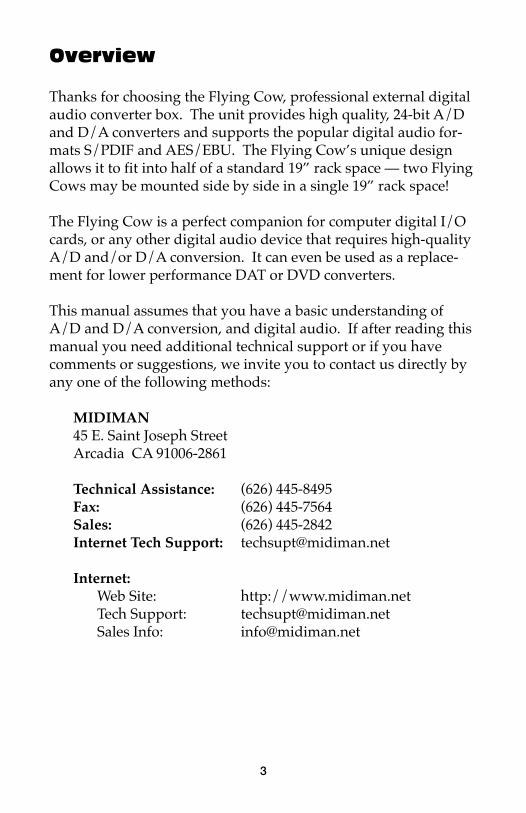
Overview
Thanks for choosing the Flying Cow, professional external digitalaudio converter box. The unit provides high quality, 24-bit A/Dand D/A converters and supports the popular digital audio for-mats S/PDIF and AES/EBU. The Flying Cow’s unique designallows it to fit into half of a standard 19” rack space — two FlyingCows may be mounted side by side in a single 19” rack space!
The Flying Cow is a perfect companion for computer digital I/Ocards, or any other digital audio device that requires high-qualityA/D and/or D/A conversion. It can even be used as a replace-ment for lower performance DAT or DVD converters.
This manual assumes that you have a basic understanding ofA/D and D/A conversion, and digital audio. If after reading thismanual you need additional technical support or if you havecomments or suggestions, we invite you to contact us directly byany one of the following methods:
MIDIMAN45 E. Saint Joseph StreetArcadia CA 91006-2861
Technical Assistance: (626) 445-8495Fax: (626) 445-7564Sales: (626) 445-2842Internet Tech Support: [email protected]
Internet:Web Site: http://www.midiman.netTech Support: [email protected] Info: [email protected]
4
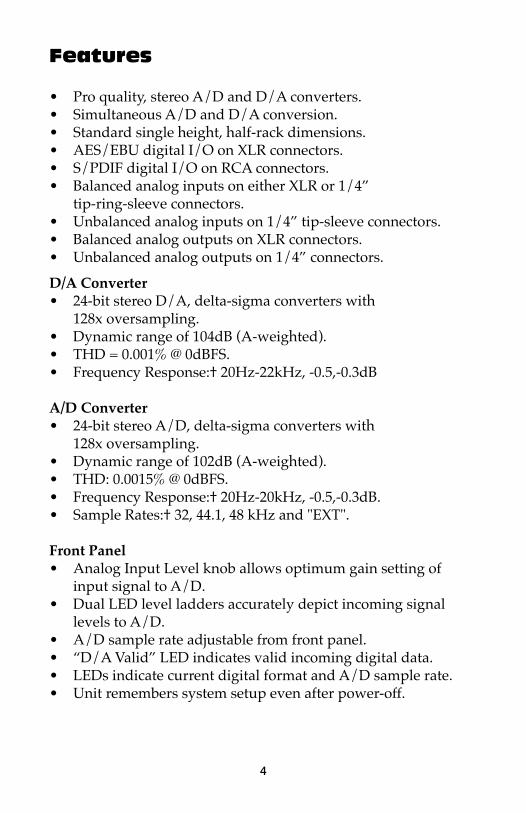
Features
• Pro quality, stereo A/D and D/A converters.• Simultaneous A/D and D/A conversion.• Standard single height, half-rack dimensions.• AES/EBU digital I/O on XLR connectors.• S/PDIF digital I/O on RCA connectors.• Balanced analog inputs on either XLR or 1/4”
tip-ring-sleeve connectors. • Unbalanced analog inputs on 1/4” tip-sleeve connectors.• Balanced analog outputs on XLR connectors.• Unbalanced analog outputs on 1/4” connectors.
D/A Converter• 24-bit stereo D/A, delta-sigma converters with
128x oversampling.• Dynamic range of 104dB (A-weighted).• THD = 0.001% @ 0dBFS.• Frequency Response:† 20Hz-22kHz, -0.5,-0.3dB
A/D Converter• 24-bit stereo A/D, delta-sigma converters with
128x oversampling.• Dynamic range of 102dB (A-weighted).• THD: 0.0015% @ 0dBFS.• Frequency Response:† 20Hz-20kHz, -0.5,-0.3dB.• Sample Rates:† 32, 44.1, 48 kHz and "EXT".
Front Panel• Analog Input Level knob allows optimum gain setting of
input signal to A/D.• Dual LED level ladders accurately depict incoming signal
levels to A/D.• A/D sample rate adjustable from front panel.• “D/A Valid” LED indicates valid incoming digital data.• LEDs indicate current digital format and A/D sample rate.• Unit remembers system setup even after power-off.
5
Panels - Fig. 1
PO
WE
RD
/AV
AL
IDD
IGIT
AL
FO
RM
AT
AE
S/
EB
US
/PD
IF48
32E
XT
44.1
MO
DE
SE
LE
CT
A/D
I NP
UT
LE
VE
LA
NA
LO
GIN
PU
TL
EV
EL
A/D
SA
MP
LE
RA
TE
L R
-40
-20
-10
-6-3
CL
IP
0M
AX
AN
AL
OG
OU
TL
RA
NA
LO
GIN
AE
S/E
BU
OU
TS
/PD
IFA
ES/E
BU
INL
R9V
AC
OU
T
IN
1.2.
3.4.
5.6.
7.
8.11
.14
.12
.13
.9.
10.FLYING
COW
™
AU
DIO
124
BIT
6
Panel Description
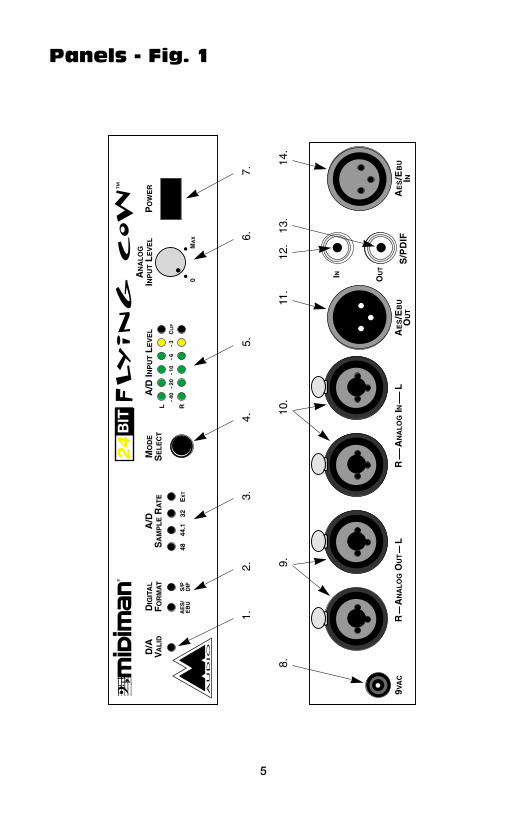
Front Panel1. D/A Valid: This LED indicates valid incoming digital data for
the D/A converter. When in AES/EBU mode, this LED lightswhenever there is a valid digital signal present at theAES/EBU In jack. When in S/PDIF mode, this LED lightswhenever there is a valid digital signal present at the S/PDIFIn jack.
2. Digital Format: These two LED’s indicate the current digitalinterface mode as either AES/EBU (professional) or S/PDIF(consumer). The mode applies to digital data both enteringand exiting the Flying Cow. The Digital Format is selected viathe Mode Select Button.
3. A/D Sample Rate: These four LED’s indicate the current sam-ple rate in use by the A/D converter (48kHz, 44.1 kHz, 32kHz, or EXT). The first three are standard sample rates. EXTis a special mode in which A/D conversion is synchronizedwith the sample rate of some external source. It is often usedto sync with less common and non-standard sample rates.
4. Mode Select: Repeatedly pressing this button will cyclethrough all of the available sample rates and digital formats.When powered up, the Flying Cow will restore the mode andsample rate that was set before the previous power-down.
5. A/D Input Level LED’s: These LED meters indicate the leftand right analog audio levels entering the A/D converter.CLIP indicates an overload condition to the A/D channel andwill result in distortion.
6. Analog Input Level: This knob sets the level of the incominganalog audio signal as it enters the A/D converter. For thegreatest dynamic range (and signal-to-noise ratio), it is best toset these levels as high as possible without making the CLIPLED’s light. When turned all the way down (0) attenuation isfull, and when turned all the way up (Max) gain is maximum.
7. Power: When this button is in, power is applied to the unit.When out, power is off. When power is turned off, the DigitalFormat and A/D Sample Rate settings are saved, and restoredupon power up.
7
Rear Panel8. Power connector: For connection to the unit’s external “wall-
wart” power supply. The Flying Cow uses an external 8.5 or9 volt A/C power supply with 1 amp or greater currentcapacity.
9. Analog Out (Right and Left): These are the analog audiooutputs from the Flying Cow’s D/A converters. These uniquecombination jacks mate with either male XLR-type connectorsor 1/4” phone plugs. The XLR (outer) portions of the jacksprovide balanced outs. The 1/4” (inner) portions provideunbalanced outs.
10. Analog In (Right and Left): These are the analog audioinputs to the Flying Cow’s A/D converters. These uniquecombination jacks mate with either male XLR-type connectorsor 1/4” phone plugs. The XLR (outer) portions of the jacksare compatible with balanced inputs. The 1/4” (inner)portions are compatible with both balanced (tip-ring-sleeve)and unbalanced (tip-sleeve) inputs.
11. AES/EBU Out: This male XLR jack provides standardAES/EBU digital output from the Flying Cow’s A/Dconverters. The digital audio signal is stereo, containingboth left and right channel data.
12. S/PDIF In: This female RCA jack accepts standard S/PDIFinput to the Flying Cow’s D/A converters. The digital audiosignal is stereo, containing both left and right channel data.This jack may also be used to accept S/PDIF “Word Clock” tothe Flying Cow when operating with EXT sample rate.
13. S/PDIF Out: This female RCA jack provides standard S/PDIFdigital output from the Flying Cow’s A/D converters. Thedigital audio signal is stereo, containing both left and rightchannel data.
14. AES/EBU In: This female XLR jack accepts standardAES/EBU input to the Flying Cow’s D/A converters. Thedigital audio signal is stereo, containing both left and rightchannel data. This jack may also be used to accept AES/EBU“Word Clock” to the Flying Cow when operating with EXTsample rate.
8
Installation and Typical Setup
Your Flying Cow box should contain this manual, a “wallwart”power transformer (U.S. customers only) and the Flying Cow unititself. Please save all packing materials in case you should everneed to ship the unit.
The Flying Cow may be operated on any flat surface or it may beinstalled in a standard 19” rack equipment tray. For installationin a 19” rack tray you will first need to remove the four rubberfeet from the unit. Next, left or right justify the Flying Cow in therack tray. Lastly, tighten the included rack-mount screw, throughthe rack tray hole, into the single threaded hole on the bottom ofthe Flying Cow chassis.
Plug in the power supply. With the Flying Cow’s power turnedoff, make your connections to any analog or digital cables youwill be using. Next, power up the Flying Cow by pressing thePower button on the front panel.
IMPORTANT: Before powering up the Flying Cow, turn downany amplifiers (or mixers) connected to the Flying Cow’s outputs.Since it takes several milliseconds for the Flying Cow to acquireand lock onto an incoming digital signal, there may be a slight“pop” sound while powering up.
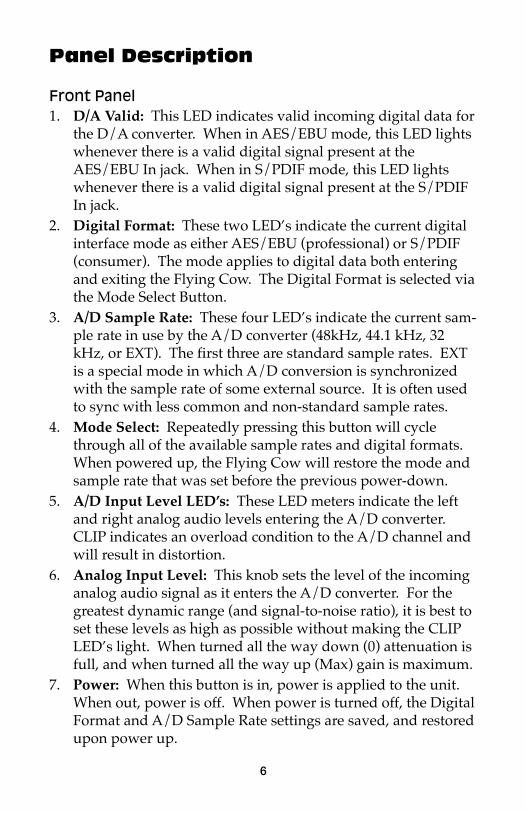
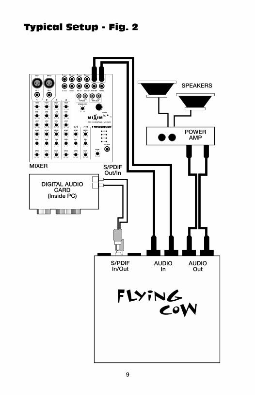
A typical configuration in which a Flying Cow would be usedincludes a Flying Cow, a PC based digital I/O card, a mixer andan amplifier/sound system (see Typical Setup figure). Such aconfiguration could be setup as follows: 1.) the unbalanced stereoaudio out of the mixer goes to the 1/4” audio inputs on the FlyingCow, 2.) the S/PDIF out of the digital audio card goes to theS/PDIF In on the Flying Cow, 3.) the S/PDIF in of the digitalaudio card goes to the S/PDIF Out on the Flying Cow, 4.) theunbalanced Analog Out on the Flying Cow goes to a line levelaudio in on the amplifier/sound system.
9
Typical Setup - Fig. 2
GAIN
•••
00 +20
• ••
•
SEND
•••
0 +6
• ••
•SEND
•••
0 +6
• ••
•SEND
•••
0 +6
• ••
•SEND
•••
0 +6
• ••
•SEND
•••
0 +6
• ••
•SEND
•••
0 +6
• ••
•
LOW
•••
-15 +15
• ••
•
MID
•••
-15 +15
• ••
•
HIGH
IN 1
MIC 1
IN 2
MIC 2
•••
-15 +15
• ••
•
LOW
•••
-15 +15
• ••
•
MID
•••
-15 +15
• ••
•
HIGH
•••
-15 +15
• ••
•
LOW
•••
-15 +15
• ••
•
MID
•••
-15 +15
• ••
•
HIGH
•••
-15 +15
• ••
•
LOW
•••
-15 +15
• ••
•
MID
•••
-15 +15
• ••
•
HIGH
•••
-15 +15
• ••
•
PAN
••L R
•
GAIN
•••
00 +20
• ••
•
PAN
••L R
•
GAIN
•••
00 +20
• ••
•
PAN
••L R
•
GAIN
•••
00 +20
• ••
•
PAN
••L R
•
GAIN
•••
00 +20
• ••
•
BAL
••L R
•
GAIN
•••
00 +20
• ••
•
BAL
••L R
•
1
5/6 7/8
2 3 4
3 mon
4 mon
5L mon
6R str
7L mon
8R str
9L mon OUT L OUT R
STR RET SEND10R str
TAPE INLEFT RIGHT
TAPE OUTLEFT RIGHT
POWER
STEREO RTN
•••
00 Max
• ••
•
PHONES
MAIN
•••
00 Max
• ••
•
- 20
0
+8
CLIP
MI IM TM
10 CHANNEL MIXERXX 10
FLYING COW
SPEAKERS
POWERAMP
MIXER S/PDIFOut/In
DIGITAL AUDIOCARD
(Inside PC)
S/PDIFIn/Out
AUDIOIn
AUDIOOut
10
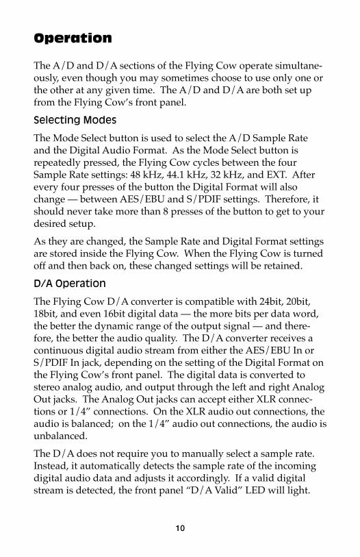
Operation
The A/D and D/A sections of the Flying Cow operate simultane-ously, even though you may sometimes choose to use only one orthe other at any given time. The A/D and D/A are both set upfrom the Flying Cow’s front panel.
Selecting Modes
The Mode Select button is used to select the A/D Sample Rateand the Digital Audio Format. As the Mode Select button isrepeatedly pressed, the Flying Cow cycles between the fourSample Rate settings: 48 kHz, 44.1 kHz, 32 kHz, and EXT. Afterevery four presses of the button the Digital Format will alsochange — between AES/EBU and S/PDIF settings. Therefore, itshould never take more than 8 presses of the button to get to yourdesired setup.
As they are changed, the Sample Rate and Digital Format settingsare stored inside the Flying Cow. When the Flying Cow is turnedoff and then back on, these changed settings will be retained.
D/A Operation
The Flying Cow D/A converter is compatible with 24bit, 20bit,18bit, and even 16bit digital data — the more bits per data word,the better the dynamic range of the output signal — and there-fore, the better the audio quality. The D/A converter receives acontinuous digital audio stream from either the AES/EBU In orS/PDIF In jack, depending on the setting of the Digital Format onthe Flying Cow’s front panel. The digital data is converted tostereo analog audio, and output through the left and right AnalogOut jacks. The Analog Out jacks can accept either XLR connec-tions or 1/4” connections. On the XLR audio out connections, theaudio is balanced; on the 1/4” audio out connections, the audio isunbalanced.
The D/A does not require you to manually select a sample rate.Instead, it automatically detects the sample rate of the incomingdigital audio data and adjusts it accordingly. If a valid digitalstream is detected, the front panel “D/A Valid” LED will light.
11
IMPORTANT: For the Flying Cow D/A converter to work prop-erly, the Digital Format must be set to the correct incoming digitalformat (AES/EBU or S/PDIF).
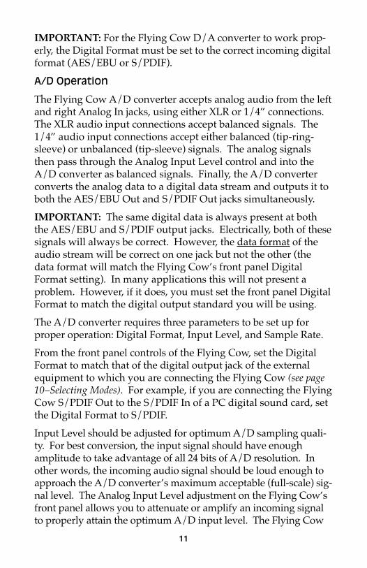
A/D Operation
The Flying Cow A/D converter accepts analog audio from the leftand right Analog In jacks, using either XLR or 1/4” connections.The XLR audio input connections accept balanced signals. The1/4” audio input connections accept either balanced (tip-ring-sleeve) or unbalanced (tip-sleeve) signals. The analog signalsthen pass through the Analog Input Level control and into theA/D converter as balanced signals. Finally, the A/D converterconverts the analog data to a digital data stream and outputs it toboth the AES/EBU Out and S/PDIF Out jacks simultaneously.
IMPORTANT: The same digital data is always present at boththe AES/EBU and S/PDIF output jacks. Electrically, both of thesesignals will always be correct. However, the data format of theaudio stream will be correct on one jack but not the other (thedata format will match the Flying Cow’s front panel DigitalFormat setting). In many applications this will not present aproblem. However, if it does, you must set the front panel DigitalFormat to match the digital output standard you will be using.
The A/D converter requires three parameters to be set up forproper operation: Digital Format, Input Level, and Sample Rate.
From the front panel controls of the Flying Cow, set the DigitalFormat to match that of the digital output jack of the externalequipment to which you are connecting the Flying Cow (see page10–Selecting Modes). For example, if you are connecting the FlyingCow S/PDIF Out to the S/PDIF In of a PC digital sound card, setthe Digital Format to S/PDIF.
Input Level should be adjusted for optimum A/D sampling quali-ty. For best conversion, the input signal should have enoughamplitude to take advantage of all 24 bits of A/D resolution. Inother words, the incoming audio signal should be loud enough toapproach the A/D converter’s maximum acceptable (full-scale) sig-nal level. The Analog Input Level adjustment on the Flying Cow’sfront panel allows you to attenuate or amplify an incoming signalto properly attain the optimum A/D input level. The Flying Cow
12
front panel A/D Input Level indicators aid in this adjustment. Setthe A/D input level knob so that you light as many level indicatorLED’s as possible without lighting the red Clip LED’s. When theClip LED’s light, the audio signal is being “clipped” at the maxi-mum allowable input level of the A/D converter. This may causeextreme distortion and should be avoided.
NOTE: For the absolute best results, set the Analog Input Levelto full attenuation (“0” setting) and externally adjust the incominganalog signals to reach the -3 dB levels at peak volume. An occa-sional CLIP reading is sometimes OK — it’s best to let your earsbe the judge!
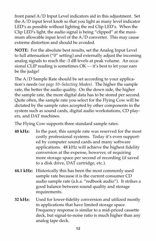
The A/D Sample Rate should be set according to your applica-tion’s needs (see page 10–Selecting Modes). The higher the samplerate, the better the audio quality. On the down side, the higherthe sample rate, the more digital data has to be stored per second.Quite often, the sample rate you select for the Flying Cow will bedictated by the sample rates accepted by other components in thesystem such as sound cards, digital audio workstations, CD play-ers, and DAT machines.
The Flying Cow supports three standard sample rates:
48 kHz: In the past, this sample rate was reserved for the mostcostly professional systems. Today it’s even support-ed by computer sound cards and many softwareapplications. 48 kHz will achieve the highest fidelityconversion at the expense, however, of requiringmore storage space per second of recording (if savedto a disk drive, DAT cartridge, etc.).
44.1 kHz: Historically this has been the most commonly usedsample rate because it is the current consumer CDaudio sample rate (a.k.a. “redbook audio”). It strikes agood balance between sound quality and storagerequirements.
32 kHz: Used for lower-fidelity conversion and utilized mostlyin applications that have limited storage space.Frequency response is similar to a mid-priced cassettedeck, but signal-to-noise ratio is much higher than anyanalog tape deck.
13
The Flying Cow also supports synchronization to an externalsource. The EXT sample rate setting locks the A/D sample rate toa valid AES/EBU or S/PDIF signal received at the digital audioinputs at the back of the unit. This is obviously useful for syn-chronization. A less obvious application is to use the externalsample rate to generate a non-standard or less common samplerate (i.e. other than 48 kHz, 44.1 kHz, or 32 kHz).
VERY IMPORTANT: In order to successfully use EXT mode, thefollowing requirements must be met: 1.) the Flying Cow’s A/DSample Rate must be set to EXT mode, 2.) the Flying Cow’sDigital Format setting must match the digital input jack that is toreceive the “sync to” data (AES/EBU In or S/PDIF In) and 3.) avalid digital data stream must be present at that selected digitalinput.
NOTE: If you have set the Sample Rate to EXT, and a valid digitalaudio signal is being received at the input selected by the DigitalFormat LED’s (AES/EBU or S/PDIF), the “D/A Valid” LED willlight. If the “D/A Valid” LED does not light then either theDigital Format is not set to the proper digital audio format or avalid digital audio signal is not reaching the appropriate digitalaudio in.
NOTE: When the A/D is in EXT mode the D/A converter con-tinues to function normally (i.e. the digital data stream beinginput to the D/A–the EXT “sync to” data in this case–will bedecoded by the D/A and analog audio will be output).
14
Troubleshooting
Symptom: When power is applied, there are no LED’s lit onthe Flying Cow’s front panel.
Solution: Make sure the power supply is properly pluggedinto the unit and also into a live wall source. Alsomake sure the Power button is pushed in (andlatched).
Symptom: When changing modes from the front panel, smallbursts of noise are sometimes present.
Solution: This is a normal and is the result of AES/EBU andS/PDIF receivers and transmitters taking a smallamount of time to lock onto a new clock frequencyor digital audio source.
Symptom: Using a tip-ring-sleeve 1/4” cable, I can’t seem toget balanced analog audio out of the Flying Cow.
Solution: The analog outputs are balanced only on the XLRconnections. The 1/4” analog output connectionsare unbalanced.
Symptom: When applying a digital signal to the Flying Cow,the “D/A Valid” LED never lights.
Solution 1: Make sure the front panel Digital Format is set tomatch the digital audio format (AES/EBU orS/PDIF) you are inputting to the Flying Cow.
Solution 2: The digital signal may be invalid or the cable goingto the digital audio in may be faulty.
Symptom: Valid digital data is coming into one of the digitalaudio inputs (the “D/A Valid” LED is lit), but thereis no audible D/A output.
Solution 1: Check your analog output connections from theFlying Cow.
Solution 2: The digital data source may be sending a static(non-changing or DC) signal. The digital audiostream is valid but the data is not changing. Or thedata represents an extremely small waveform thatyou are unable to hear.
15
Symptom: Even though the front panel Analog Input Levelknob is set to the MAX setting, none of the InputLevel LED’s light.
Solution 1: Check your source signal and analog input cables.Solution 2: The input signal is too weak. Turn up the volume
of the source — the lower you can set the AnalogInput Level knob the better the signal-to-noise per-formance achieved.
Symptom: Even though the front panel Analog Input Levelknob is turned all the way down (0), all of theInput Level LED’s and even the CLIP LED oftenlight.
Solution 1: Check your source signal and analog input cables.Solution 2: The input signal is too strong. Reduce the volume
of the source and try to keep the Analog InputLevel knob set to “0” if possible. This will achieveoptimum signal-to-noise performance.
Symptom: With the A/D in EXT mode, the Flying Cow is out-putting erroneous digital data even though I thinkthere is a valid digital audio signal coming into theunit. The “D/A Valid” LED does not light.
Solution: If the “D/A Valid” LED does not light then: 1.) theDigital Format is not set to the proper digital audioformat, OR 2.) a valid digital audio signal is notreaching the correct digital audio in. This couldhappen if you are using the wrong digital audio inor if the digital audio cable is bad or if the deviceyou are using to produce the sync signal is mal-functioning. If any of these mishaps have occurredthen the “D/A Valid” LED will not light and theFlying Cow will convert A/D data at a rate that isunpredictable (typically between 10 kHz and32 kHz).
16
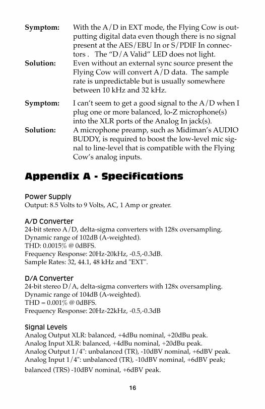
Symptom: With the A/D in EXT mode, the Flying Cow is out-putting digital data even though there is no signalpresent at the AES/EBU In or S/PDIF In connec-tors . The “D/A Valid” LED does not light.
Solution: Even without an external sync source present theFlying Cow will convert A/D data. The samplerate is unpredictable but is usually somewherebetween 10 kHz and 32 kHz.
Symptom: I can’t seem to get a good signal to the A/D when Iplug one or more balanced, lo-Z microphone(s)into the XLR ports of the Analog In jack(s).
Solution: A microphone preamp, such as Midiman’s AUDIOBUDDY, is required to boost the low-level mic sig-nal to line-level that is compatible with the FlyingCow’s analog inputs.
Appendix A - Specifications
Power SupplyOutput: 8.5 Volts to 9 Volts, AC, 1 Amp or greater.
A/D Converter24-bit stereo A/D, delta-sigma converters with 128x oversampling.Dynamic range of 102dB (A-weighted).THD: 0.0015% @ 0dBFS.Frequency Response: 20Hz-20kHz, -0.5,-0.3dB.Sample Rates: 32, 44.1, 48 kHz and "EXT".
D/A Converter24-bit stereo D/A, delta-sigma converters with 128x oversampling.Dynamic range of 104dB (A-weighted).THD = 0.001% @ 0dBFS.Frequency Response: 20Hz-22kHz, -0.5,-0.3dB
Signal LevelsAnalog Output XLR: balanced, +4dBu nominal, +20dBu peak.Analog Input XLR: balanced, +4dBu nominal, +20dBu peak.Analog Output 1/4": unbalanced (TR), -10dBV nominal, +6dBV peak.Analog Input 1/4": unbalanced (TR), -10dBV nominal, +6dBV peak;
balanced (TRS) -10dBV nominal, +6dBV peak.
17
Appendix B - Diagnostic Tests
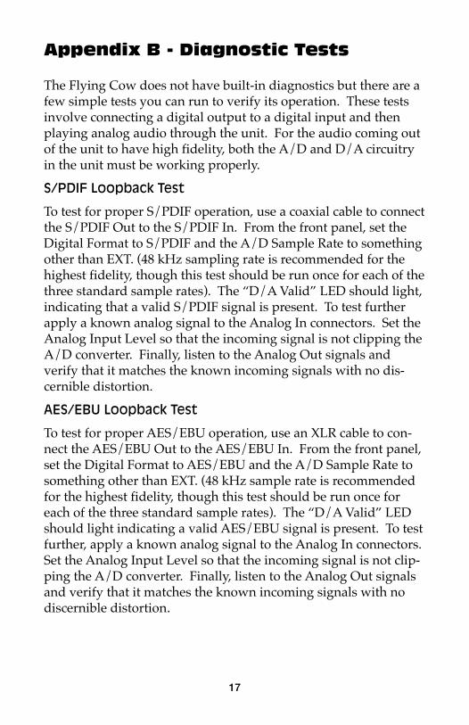
The Flying Cow does not have built-in diagnostics but there are afew simple tests you can run to verify its operation. These testsinvolve connecting a digital output to a digital input and thenplaying analog audio through the unit. For the audio coming outof the unit to have high fidelity, both the A/D and D/A circuitryin the unit must be working properly.
S/PDIF Loopback Test
To test for proper S/PDIF operation, use a coaxial cable to connectthe S/PDIF Out to the S/PDIF In. From the front panel, set theDigital Format to S/PDIF and the A/D Sample Rate to somethingother than EXT. (48 kHz sampling rate is recommended for thehighest fidelity, though this test should be run once for each of thethree standard sample rates). The “D/A Valid” LED should light,indicating that a valid S/PDIF signal is present. To test furtherapply a known analog signal to the Analog In connectors. Set theAnalog Input Level so that the incoming signal is not clipping theA/D converter. Finally, listen to the Analog Out signals andverify that it matches the known incoming signals with no dis-cernible distortion.
AES/EBU Loopback Test
To test for proper AES/EBU operation, use an XLR cable to con-nect the AES/EBU Out to the AES/EBU In. From the front panel,set the Digital Format to AES/EBU and the A/D Sample Rate tosomething other than EXT. (48 kHz sample rate is recommendedfor the highest fidelity, though this test should be run once foreach of the three standard sample rates). The “D/A Valid” LEDshould light indicating a valid AES/EBU signal is present. To testfurther, apply a known analog signal to the Analog In connectors.Set the Analog Input Level so that the incoming signal is not clip-ping the A/D converter. Finally, listen to the Analog Out signalsand verify that it matches the known incoming signals with nodiscernible distortion.
A/DCONVERTER
A/DCONVERTER
AES/EBU
S/PDIF
Digital Format(changed by Mode Select
Switch)
48 44.1 32 Ext
A/DSample Rate
(changed by Mode Select
Switch)
Mode Select Switch
Mode Select Switch
AES/EBU
DIGITALOUTPUTS
XLR
LEFT ANALOG INPUT
ANALOGINPUTLEVEL
1/4"
LEDLadder
XLR
RIGHT ANALOG INPUT
ANALOGINPUTLEVEL
1/4"
LEDLadder
S/PDIF
AES/EBU
DIGITALINPUTS
S/PDIFAES/EBU
S/PDIF
Digital Format(changed by Mode Select
Switch)
Extracted Clock
XLR
1/4"
LEFT ANALOG OUTPUT
XLR
1/4"
RIGHT ANALOG OUTPUT
D/ACONVERTER
D/ACONVERTER
Mode Select Switch
18
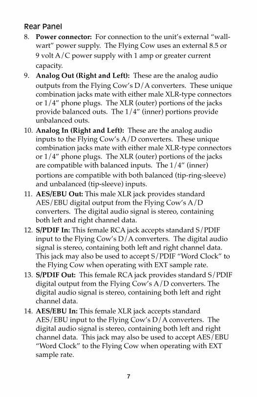
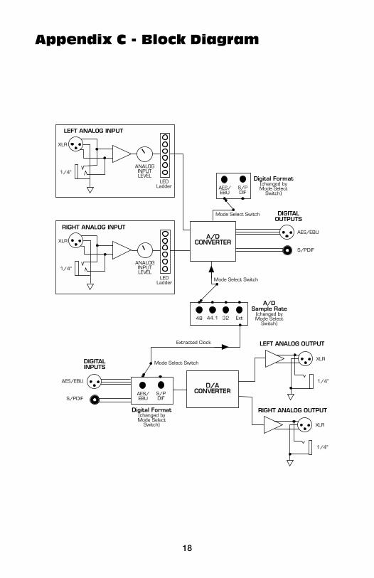
Appendix C - Block Diagram
19
JP2
JP5
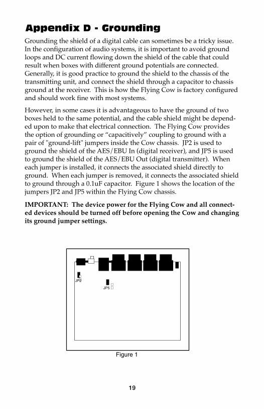
Figure 1
Appendix D - GroundingGrounding the shield of a digital cable can sometimes be a tricky issue.In the configuration of audio systems, it is important to avoid groundloops and DC current flowing down the shield of the cable that couldresult when boxes with different ground potentials are connected.Generally, it is good practice to ground the shield to the chassis of thetransmitting unit, and connect the shield through a capacitor to chassisground at the receiver. This is how the Flying Cow is factory configuredand should work fine with most systems.
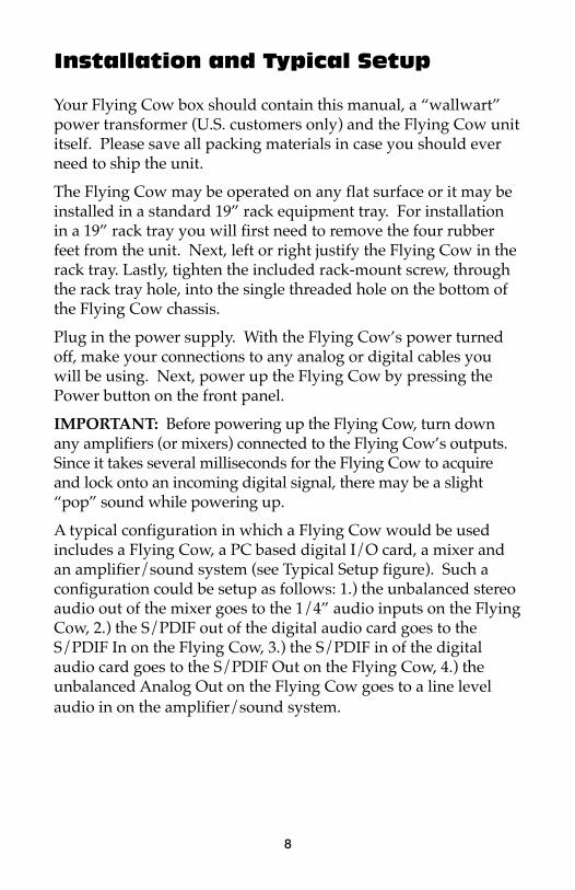
However, in some cases it is advantageous to have the ground of twoboxes held to the same potential, and the cable shield might be depend-ed upon to make that electrical connection. The Flying Cow providesthe option of grounding or “capacitively” coupling to ground with apair of "ground-lift" jumpers inside the Cow chassis. JP2 is used toground the shield of the AES/EBU In (digital receiver), and JP5 is usedto ground the shield of the AES/EBU Out (digital transmitter). Wheneach jumper is installed, it connects the associated shield directly toground. When each jumper is removed, it connects the associated shieldto ground through a 0.1uF capacitor. Figure 1 shows the location of thejumpers JP2 and JP5 within the Flying Cow chassis.
IMPORTANT: The device power for the Flying Cow and all connect-ed devices should be turned off before opening the Cow and changingits ground jumper settings.
20
Lifetime Limited Warranty
MIDIMAN warrants that this product is free of defects in materials and work-manship under normal use so long as the product is owned by the original pur-chaser and that purchaser has registered his/her ownership of the product bysending in the completed warranty card.
In the event that MIDIMAN receives written notice of defects in materials orworkmanship from such an original purchaser, MIDIMAN will either replace theproduct, repair the product, or refund the purchase price at its option. In theevent any repair is required, shipment to and from MIDIMAN and a nominalhandling charge shall be born by the purchaser. In the event that repair isrequired, a Return Authorization number must be obtained from MIDIMAN.After this number is obtained, the unit should be shipped back to MIDIMAN ina protective package with a description of the problem and the ReturnAuthorization clearly written on the package.
In the event that MIDIMAN determines that the product requires repair becauseof user misuse or regular wear, it will assess a fair repair or replacement fee. Thecustomer will have the option to pay this fee and have the unit repaired andreturned, or not pay this fee and have the unit returned unrepaired.
The remedy for breach of this limited warranty shall not include any other dam-ages. MIDIMAN will not be liable for consequential, special, indirect, or similardamages or claims including loss of profit or any other commercial, damage,even if its agents have been advised of the possibility of such damages, and in noevent will MIDIMAN’s liability for any damages to the purchaser or any otherperson exceed the price paid for the product, regardless of any form of the claim.MIDIMAN specifically disclaims all other warranties, expressed or implied.Specifically, MIDIMAN makes no warranty that the product is fit for any partic-ular purpose.
This warranty shall be construed, interpreted, and governed by the laws of thestate of California. If any provision of this warranty is found void, invalid orunenforceable, it will not affect the validity of the balance of the warranty, whichshall remain valid and enforceable according to its terms. In the event any reme-dy hereunder is determined to have failed of its essential purpose, all limitationsof liability and exclusion of damages set forth herein shall remain in full forceand effect.