fluxgate magnetometer for space application
TRANSCRIPT

MARCH-APRIL 1964 ION PROPULSION FOR STATIONARY-SATELLITE CONTROL 175
The vertical dotted lines represent typical ratios of maximumtorque to moment of inertia for satellites in the 500- to 1500-Ib class. The weight of the power supply for an ion propul-sion attitude-control system for such satellites will be lessthan 10 Ib (Fig. 10). In the semicontinuous North-Southmode of operation, the engines are operated directly from thesolar cells so that no energy storage system is needed for thestation-keeping system. However, about 30 w-hr of energystorage capability will be required to operate the attitude-control engines during the time the vehicle spends in theearth's shadow (a maximum of 1.16 hr/day). Typicalattitude-control and station-keeping system weights requiredfor a 1000-lb vehicle when using the continuous station-keeping thrust mode are shown in Table 4.
Conclusions
Three-axes attitude control and station keeping of a sta-tionary satellite are well within the capabilities of ion pro-pulsion systems. Some of the problems peculiar to thisapplication of ion engines, such as the need for extremely lowionizer warmup energy, are already near solution, and others,such as engine reliability after thousands of thrust pulses,
will be accomplished and demonstrated in the near future.A prototype system of the type described in this paper hasbeen developed and laboratory tested. A comparison ofthe weights of several types of attitude-control and station-keeping systems (as discussed by Boucher2) has shown thatas the desired lifetime of satellites extends to more than oneyear, the ion propulsion system emerges as the lightestattitude-control and station-keeping system presently underdevelopment.
References1 McElvain, R. J., "Effects of solar radiation pressure upon
satellite attitude control," ARS Preprint 1918-61 (August 1961).2 Boucher, R. A., "Electrical propulsion for control of station-
ary satellites," J. Spacecraft Rockets 1, 164-169(1964).3 Ehricke, K. A., "Dynamics," Space Flight (D. Van Nostrand,
Inc., Princeton, N. J., 1962), Vol. II, pp. 144-150.4 Jensen, J., Townsend, G. E., Kraft, J. D., and Kork, J., Design
Guide to Orbital Flight (McGraw-Hill Book Co., Inc., N. Y., 1962),p. 138.
5 Molitor, J. H. and Kaplan, M. H., "Optimization of ionengine control systems for synchronous satellites," AIAA Pre-print 63-273 (June 1963).
MARCH-APRIL 1964 J. SPACECRAFT VOL. 1, NO. 2
Fluxgate Magnetometer forSpace Application
S. C. LING*Therm, Inc., Ithaca, N. Y.
A new type of fluxgate magnetometer based on the principle of minimum flux linkage be-tween the gating field and the ambient field is developed for space application wherein fieldstrengths of the order of a few gammas are to be detected. Through the unique combina-tion of several physical properties of the magnetometer, a stable decoupling factor of the orderof 10~7 is achieved. A phenomenological theory is presented to explain the general mechanicsof the fluxgate, and a discussion of the spectrum of transverse induction is made. Experi-mental values for a typical magnetometer and its circuitry are presented in order to demon-strate its working principle.
Introduction
AN advanced type of fluxgate magnetometer was de-veloped for space applications, in which magnetic field
strengths of the order of a few gammas (17 = 10~5 gauss)are to be detected. In order to measure such weak fields,one must find a way to minimize effects of the disturbancesdue to the presence of the space vehicle and its associated
Presented as Preprint 63-187 at the AIAA Summer Meeting,Los Angeles, Calif., June 17-20, 1963; revision received January6,1964.
* Head, Experimental Section; now Research AssociateProfessor, Department of Space Sciences and Applied Physics,Catholic University of America, Washington, D. C. Thiswork was carried out on behalf of NASA, under contract NASr-46, with the Center for Radiophysics and Space Research ofCornell University. The author wishes to thank T. Gold for hisgeneral guidance on this project and H. S. Tan for his invaluableadvice and inspiration. Acknowledgment is also due to H.Eckelmann for his assistance in experimental investigationsand circuit design.
controls and instruments. Realizing this fact, T. Gold urgedthe development of a magnetometer sufficiently small andsensitive to be attached to the end of a boom 20 to 30 ftaway from the vehicle, so that the disturbing magnetic fieldwould be reduced to an acceptable level according to theinverse-distance-cubed law. This concept led to the de-velopment of an improved fluxgate magnetometer, which isdescribed in this paper.
In general, a fluxgate magnetometer works on the prin-ciple of gating the ambient field by modulating the per-meability of a piece of magnetic material through the applica-tion of an alternating gating field. The resultant modulatedambient field is an even function of the gating field, and thevoltage induced in a signal coil which links these fluctuatingflux fields contains the fundamental frequency of the gatingfield and the even harmonics of the gated ambient field. Inorder to detect an ambient field of the order of 0.17 a stablerejection factor for the fundamental frequency of the orderof 10~9 would be needed, because the gating field density formost magnetic materials is of the order of 1087. The stand-ard technique is to employ the method of direct bucking
Dow
nloa
ded
by R
MIT
UN
IV B
UN
DO
OR
A o
n O
ctob
er 9
, 201
3 | h
ttp://
arc.
aiaa
.org
| D
OI:
10.
2514
/3.2
7618

176 S. C. LING J. SPACECRAFT
GATING COIL
i
(
r
-
\J-
1\,\\ ,\\
-r1
—4'
_4'
1 _
\
-\ s
r-< X
^SIGNAL CO
d =
)
•^^-FERRITETU
2.8mmd=0.9mm
Fig. 1 Axially symmetrical fluxgate sensor.
of the fundamental frequency by means of two preciselymatched and aligned pairs of sensors,1 and to remove theresidual fundamental frequency by a sharp cutoff filter ortuned amplifiers. Although a rejection factor of the orderof 10~9 can be realized in the controlled environment of alaboratory, it is questionable that the critical 10 ~5 balanceof the bucking system can be maintained under space en-vironment, because both systems are pushed beyond thepractical limit of 10~3, and, in addition, neither system canreject random noise within the passband of the filter.
A search was therefore made for combinations of physicalproperties which might lead to an improvement of the re-jection factor. It was found that by combining propertiesof the material due to its physical structure and geometry,a magnetometer with a self-decoupling factor of the orderof 10~7 is realized. The term decoupling factor is definedas the fraction of the total gating-flux field that is linkedwith the signal coil. This method, based on the minimumflux linkage between the gating field and the ambient field,is superior in many respects to the direct bucking principlejust mentioned. In the following sections, detailed proper-ties and theories of this improved magnetometer will bediscussed.
Physical Principles
The physical arrangement of an axially symmetricalmagnetometer is shown in Fig. 1. The magnetic core is inthe form of small ferrite tubing with a large length-to-diameter ratio. A toroidal gating coil is wound through thetubing. In order to achieve a zero net winding pitch withone layer of winding, all wires along the ferrite tubing arekept parallel to the mechanical axis and the winding pitchis taken up at the ends of the tubing. The end windingpitches are crisscrossed to achieve zero net pitch. A signalcoil is wound in the form of a solenoid coaxial with the ferritetubing and perpendicular to the gating coil. This windingconsists of even number of layers, so as to obtain a zero netwinding pitch. To reduce electrostatic coupling, an electro-static shield is placed in between the gating coil and thesignal coil. The assembly is then mounted with sliding end-supports inside a precision quartz tube. This method ofsuspension minimizes stresses due to external load andthermal expansion.
Large decoupling factors, based on the principle of mini-mum flux linkage between the gating field and the ambient
field, can be achieved by the combination of several physicaland geometrical properties. The first step is to apply thebottling property of a toroidal coil: All of the field generatedby a toroidal coil is confined within the toroid if the netwinding pitch is zero.2 Next is the utilization of the propertyof precise orthogonality between the gating and the signalcoil. The last important step is to place within the toroidalcoil a magnetic material that has a preferred direction ofmagnetization in the circumferential 6 direction, i.e., in theHe field direction of the gating coil. From the geometricshape of the ferrite tubing it can be shown that the 6 directionis the easiest direction of magnetization, because in thisdirection the magnetic path is the shortest and closed sothat there is no external demagnetization field. The effec-tive magnetic reluctance in the 6 direction, pe, can be ex-pressed in terms of its geometry and the initial permeabilityof material JJLQ :
where D is the mean tube diameter, d the wall thickness,and I the length of tube. The next easy direction of mag-netization is along the axial direction. Here the externaldemagnetization field has to be taken into consideration,and the effective reluctance in the axial direction pr is
Pr =4:1
(2)
where /zr, the apparent permeability of tube, is a functionof l/D ratio and JJLO. The function can be found in publisheddata.3 Portions of the data useful for the present workare replotted in Fig. 2.
To achieve a high decoupling factor, the ratio of reluc-tances,
pepr
(3)
must be made as small as possible.If l/D is made large, the reluctance ratio can be made very
small. In the present design, the ratio of reluctance is ofthe order of 10~3. Combining this ratio with that of theminimum coupling property of the signal and gating coils, adecoupling factor of the order of 10~7 has been obtained andverified by experiment. (A magnetometer constructed withonly normal care will give a decoupling factor of the orderof 10~6, but one built with due care and adjustment can give10~7.) In order to obtain a total of 10~9, the remainingfactor of 10~2 is obtained by a standard filtering technique.
The axially symmetric gating field in the form of a toroidcontributes to certain important properties. The He fieldwithin the ferrite tubing is quite uniform; hence, all of the
Mr
10
0 200 4OO 600 800 1000 1200 1400 1600 1800M0 , MX
Fig. 2 The apparent permeability of a rod in an externalfield as a function of permeability of material.
Dow
nloa
ded
by R
MIT
UN
IV B
UN
DO
OR
A o
n O
ctob
er 9
, 201
3 | h
ttp://
arc.
aiaa
.org
| D
OI:
10.
2514
/3.2
7618

MARCH-APRIL 1964 FLUXGATE MAGNETOMETER FOR SPACE APPLICATION 177
material is subjected to uniform saturation by an alternatinggating field, and the possibility of retaining a large residualmagnetism, after subjecting the magnetometer to a strongambient field, is greatly reduced. Experimental resultshave indicated that after the magnetometer is subjected toa field less than saturation it can recover to its originallevel practically instantaneously. For field strengths greaterthan saturation, its recovery time is greatly increased to theorder of minutes. On the other hand, the minimum leakageof gating flux and flux coupling between the orthogonal coilshave essentially decoupled the random noise (one componentof the Barkhausen noise), generated by the gating field,from the signal coil. If the noise field is assumed to beessentially in the 6 plane, and its magnitude is much smallerthan the average gating flux, the resultant noise voltagethus coupled into the signal coil is expected to be severalorders smaller than the minimum signal to be detected. Thelow-frequency components of Barkhausen noise usually pro-duce undesirable low-level signal drift.4 The completedecoupling of this effect on the present design is an importantcontribution toward the stability of the zero level.
This type of magnetometer can provide very large signaloutputs; with proper coil design and driving circuitry,signals of the order of few millivolts per gamma are typicallyproduced. At this output level, there is, in general, noneed for any further voltage amplification. The signal-coiloutput impedance is of the order of 105 ohms, so that a com-mon collector transistor circuit can be used to transform theoutput impedance to the order of 102 ohms, without signifi-cant loss in output signal. At this impedance and signal-output level, the problems of coupling of stray signals andthe stability of associated processing circuitry are greatlyalleviated. The resultant simplicity of supporting circuitryshould, as a rule, enhance the over-all reliability of the mag-netometer. Further, it is insensitive to mechanical vib-ration, because of its new gating principle (quite differentfrom the standard direct-bucking principle that relies on theabsolute symmetry of two large signal sources under alldisturbing environmental variables and conditions). It isimportant to note that the principle of self-decoupling factor,based on minimum flux linkage, automatically reduces theenvironmental variables by a large factor, and thus eliminatesall delicate balancing and matching operations.
General Theory of Fluxgate
Principle of Fluxgate
The principle of orthogonal gating is not new, the generaltheory having been advanced by Zhukova,5 Gorelik,6 andPalmer.7 Most of their works are intended for wire-typemagnetometers in which the gating current through themagnetic wire creates its own circular saturating field, whilethe ambient field or its component is lined up with the wireaxis. Although considerable effort has been put on this
/locus of B vector /'ocus of H vector
3
DO 2
10 20H , oersted
30 40
Fig. 4 Vector diagram of B and H field beyond saturation.
subject, there is as yet no exact theory that can fully accountfor gating characteristics observed experimentally. Thereason is that most magnetic materials are not isotropic.They also exhibit hysteresis which, under a rotating mag-netizing field, is as yet intractable analytically. This paperdoes not attempt to go into detail in the solid-state physicsof magnetic materials, but will touch upon some phenomeno-logical theories of orthogonal gating which lend reasonableexplanations for the gating mechanism.
The object here is to find out the functional relationshipbetween the apparent axial permeability of the magnetometerjur and the orthogonal gating field He. It is expedient torefer jur to the differential permeability of the magnetic mate-rials MX in the same axial direction. The apparent perme-ability jjLr is a function of px and geometry. Their functionalrelationship is shown in Fig. 2 for a cylindrical rod. Thisfunction also may be considered valid for thick-walled tubingused in the present problem.
The functional relationship between JJLX and the orthogonalgating field HQ cannot be fully accounted for by the presenttheories. The standard B-H characteristics of one dimensionare not applicable to a rotating // field. However, for afield strength H above saturation PIS, we may assume theB vector to be colinear with the H vector.8 For simplicity ofpresentation, Hs and Bs are defined as the knee point of twostraight lines which represents the B-H curve of a given mate-rial, as shown in Fig. 3. Figure 4 shows the vector diagramof the resultant H vector for a varying orthogonal gatingfield He and a small steady axial field Hx. For the presentapplication, Hx is of the order of 10~7 of the average gatingfield He. Therefore, for He » Hs one may take | H | to bethe same as |He and the resultant \B\ to be equal to |Be|.When the H field is greater than HS) the B vector reaches thelimit of saturation density BS) and the locus of the B vectoris an arc described by BS) as the angle <£ of the total H vectorreduces with increasing He. From the vector diagram, wesee that the component of Bx is approximately
Bx = H. § = (He \
Hx H,» H, (4)
or
Fig. 3 B-H curve for type A-3 manganese-zinc ferrite.
(5)
When the peak value of He is 20 times HSf M* is reduced to5%, or a gate closure of 95%. However, in actual case, theclosure was found to be about 85% for a typical magnetom-eter, as shown in Fig. 5.
On the right-hand side of Fig. 5 is the experimental curveof apparent permeability Mr/Mr max as a function of He/Hs.This is obtained by measuring the change in inductance ofthe signal coil as a function of He. The ratio Mr/Mr max isslightly less than unity at He = 0, and there is a small hys-teresis loop around this region. An important property oforthogonal gating, as shown here, is that jj,r does not exhibitany double peaking effect as those associated with parallelgating.9 This means that the magnetic retentivity in theaxial direction due to the strong orthogonal gating field isnegligibly small. Through the known relationship betweenMX and Mr (see Fig. 2), the functional relationship betweenMX and He is plotted on the left-hand side of Fig. 5. It willbe noted that the closure of apparent permeability Mr ismuch less than M*.
Dow
nloa
ded
by R
MIT
UN
IV B
UN
DO
OR
A o
n O
ctob
er 9
, 201
3 | h
ttp://
arc.
aiaa
.org
| D
OI:
10.
2514
/3.2
7618

178 S. C. LING J. SPACECRAFT
1.0
-Eg. 5
0.8-
0.6-
0.4-
0.2-
0
= 20
20 15 10 5 10 15 20
Fig. 5 Apparent permeability of tubing and axial per-meability of material as a function of H9/HS.
In the present design, it is arbitrarily decided to use apeak gating-neld strength of He = 20//s, since higher gatingfields will run into uneconomical power consumption andheat-removal problems. At this gating level, one is assuredof quick pulldown of any large residual magnetism that themagnetometer might have acquired during operation.
When we drive the magnetometer at a high He/H, ratio,we have to operate the gating coil as a highly nonlinearinductor. The problem then is to find the best over-alldriving characteristic for this inductor so as to producemaximum signal with minimum noise and power consump-tion. In the present design, the gating coil is connected inparallel with a condenser to form an oscillating tank so that,during the saturation period, the condenser is capable ofdumping high current into the coil to produce the largepeak He field required for gating operation.
The fundamental self-relaxation frequency of the tank isapproximately
- Eg/2LsIs (6)
where Eg is the average peak voltage across the tank be-tween gating cycle, Lg is the average initial inductance ofthe gating coil, and Is is the current required for saturatingthe inductor. From the consideration of transistor drive,the average peak tank voltage in the present design is limitedto 4 v, or 8 v peak-to-peak. The gating coil contains 14turns of #28 wire to give an Lg value of about 1.5 mh. Thecurrent Is required is about 0.1 amp. With these values for
Eq. (6), we obtain a relaxation frequency fg of about 10kc/sec.
There are two possible methods for driving the gate. Oneis to connect the tank in a transistor drive circuit to forma self -relaxation oscillator; the other is to drive it by an inde-pendent power oscillator with a frequency substantially lowerthan fe. For various reasons the latter method was adopted,and a driving frequency of 5.5 kc/sec was used.
Figure 6 shows the gating current, or rather the gatingfield Pie, as a function of time. No attempt will be madeto present the complex solution for this function in rela-tionship to the tank and its drive circuit since analyticaltreatment on this subject has been made by Ku.10 Thegating wave of the present design is in the form of very sharpalternating pulses with a peak current of about 2.2 amp, or afield strength of about 40 oe. The PR power loss is about0.15 w, where R is the resistance of the gating coil and cableleads; the hysteresis loss in the ferrite tubing is of similarmagnitude, so that the total gating loss for the sensor is about0.3 w.
Also shown in Fig. 6 is the gating flux Be . This curve ishighly distorted due to hysteresis. The corresponding gat-ing of ambient-flux field, shown in terms of Mr/Mr max in thelower part of the figure, was obtained through the functionalrelationship between jur and He (Fig. 5). It is interestingto note that due to hysteresis, jur closes, or decreases, a littlefaster than when it is opening. The closure rate dependslargely on the initial rate of rise of the He pulse. The out-put voltage across the signal coil is proportional to the timederivative of Br(t) or, in turn, the time derivative of jj,r(t).By taking the time derivative of the /zr/Mr max curve, we ob-tain the voltage wave which is plotted as EC/EC max in Fig. 6.It will be noted that this signal wave is unsymmetricalabout the zero line and that it contains the second and higherharmonics of the fundamental gating frequencies. It is evi-dent that a better and cleaner second harmonic signal can beobtained if the gating action were timed evenly at the quarterphase points, but this will require unduly wide He pulseswhich, in turn, means very large PR loss.
The signal coil in the present design contains about 1600turns of #36 wire, and is tuned to the second harmonic by acondenser in parallel with the coil. The Q of the coil is about40, so the output voltage E% across the tuned tank is aboutQ times the second-harmonic signal component of Ec:
where
E2 = K,ECQ (7)
is the coefficient of second harmonic of Ec.
-i.o-
Spectrum of Transverse Induction
So far we have treated the problem of an ideal magne-tometer, ignoring inhomogeneity of magnetic materials,nonsymmetry in geometrical shape, and stresses due toexternally applied load or internally generated stress. Nowwe must find out how these variables will affect the outputsignal in terms of the various frequency components. Weshall consider the magnetic materials to be nonisotropic ;the general expression for the permeability tensor is
Fig. 6 Periodic wave forms of gating field, apparent per-meability, and damped output signal.
HX)(?'} sign#0). Wre shall consider Hx and the principlestress o- to be fixed parameters, while He is a periodic func-tion of time, He = He0ei(at.
The transverse or axial induction Rx, due to the gating ac-tion of H j is also a periodic function of time, and it can be ex-pressed in the general form
Bx = VLxx(He,HX)<r', sign#0)#x +^(Hoiff*,*; sign#*)#0 (8)
The permeability tensor can be written as the sum of triplepower series. Following the method of Zhukova,5 which isbased on the consideration of symmetry, we have the ex-
Dow
nloa
ded
by R
MIT
UN
IV B
UN
DO
OR
A o
n O
ctob
er 9
, 201
3 | h
ttp://
arc.
aiaa
.org
| D
OI:
10.
2514
/3.2
7618
MARCH-APRIL 1964 FLUXGATE MAGNETOMETER FOR SPACE APPLICATION 179
pression for Bx :
Bx(t) = Zamnpf
(9)
where a, ft f, and 6 are coefficients. The hysteresis loopis expressed by the bivalued function. The =fc sign is to betaken as positive when dHo/dt > 0, and negative when dHe/<5t < 0. It can be shown that the bivalued function makesodd functions of He even, and even functions of He odd. Thebasic effect of hysteresis is to cause a small phase shift toall of the frequency components. In general, the first andthird right-hand terms of the previous expression represent thesecond and higher even harmonics of He, whose coefficientsare odd functions of Hx, and even functions of cr, whereasthe second and fourth terms represent the fundamental andhigher odd harmonics of He whose coefficients are even func-tions of Hx and odd functions of cr. Since the second andfourth terms represent the undesirable leakage flux, we shalldesignate them the "leakage magnetism."
In operation, all frequencies except the second-harmoniccomponent are filtered out. The contribution of second-harmonic component due to small Hx and cr is proportionalto
Hx(l + ao-2)
where a is a constant. The amplitude of Bx is therefore alinear function of Hx, and its phase position is determined bythe sign of Hx alone, and not by He nor cr. The contribu-tion due to cr is not objectionable as long as acr2 <C 1 andstays constant.
The contribution of fundamental-frequency componentfor small Hx and o is proportional to
where b is a constant. If the gating field He contains nosecond harmonic, there is no contribution of second-harmonicsignal by this term. However, if the reverse is true, thenthe second harmonic contributed b}^ this term is quite unde-sirable because it is an even function of Iix. Its effect isequivalent to a permanent magnetism whose phase positionis independent of the sign of Hx. It is, therefore, quiteimportant to have minimum second-harmonic componentin HO. However, in the present design, due to the inherentself-decoupling factor, a maximum second-harmonic contentof 0.1% of the fundamental component of He is consideredacceptable (i.e., equivalent to a signal level of 6.017).
The "leakage magnetism'7 can be detected at the outputof the signal coil by reversing the polarity of He. Thesecond-harmonic component that changes sign with He is the"leakage magnetism" since it is an odd function of He.
Electronic Circuits
From the previous discussion of the basic principle of thesensor, one sees that there are many ways of driving thefluxgate, as well as processing its output signal. In thispaper one basic design is presented.
In general, the sensor is to be incorporated in a self-balancing (or servo) system in which a current is fed backinto the signal coil, or a separate secondary coil, to balanceout the ambient field. The feedback current is then cali-brated as a function of the ambient field. In this mode ofoperation, one achieves minimum disturbance to the ambientfield because the magnetic reluctance pr is increased by afactor of 1000, on account of the suppression factor of theservo. This then will permit the placement of three orthog-onally oriented sensors in close proximity and free from theeffect of interreaction.
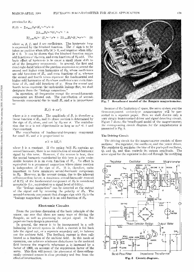
Fig. 7 Breadboard model of the fluxgate magnetometer.
Because of the limitation of space, the servo system and thethree-component vector-type magnetometer will be pre-sented in a separate paper. Here we shall discuss only avery simple transistorized driver and signal detecting circuit.Figure 7 shows the breadboard model of the magnetometer;the corresponding circuit diagram for the magnetometer ispresented in Fig. 8.
The Driving Circuit
The driving circuit for the magnetometer consists of threesections: the regulator, the oscillator, and the power driver.The regulator Qi regulates the bias of the push-pull oscillator,Q2 and Q3, and thus controls its output amplitude. Theerror signal for the regulator is derived through the rectifying
Regulator Oscillator Driver MagnetometerH
Phase-Detector-Bridge Output Meter
Band-Pass Filter Impedance Transformer^Fig. 8 Circuit diagram.
Dow
nloa
ded
by R
MIT
UN
IV B
UN
DO
OR
A o
n O
ctob
er 9
, 201
3 | h
ttp://
arc.
aiaa
.org
| D
OI:
10.
2514
/3.2
7618

180 S. C. LING J. SPACECRAFT
diedos D\ across the gating coil of the magnetometer, and thetrimpot RI is used for setting the regulator to control thepeak gating current at 2.2 amp. The frequency of the oscil-lator is determined by the LiCi tank circuit, which is tunedto 5.5 kc/sec. The large common-emitter resistor R2 pro-vides the automatic suppression of second harmonic. Thepower drivers $4 and Q5 are operated in a class B conditionfor minimum power consumption, and each dissipates ap-proximately J w. The transformer T2 is used for matchingthe impedance of the magnetometer to the power driver.Condenser C2 is the tank capacitor for the gating coil Lg.Its value is chosen to provide the desired gating wave formas shown in Fig. 6.
In operation, when the power switch SWi is turned on,the gating current is zero. The regulator is biased to cutoffand the oscillator is allowed to run at its maximum ampli-tude, which is almost twice the value necessary for startingthe magnetometer into its saturation cycles. As soon as thishappens, the regulator starts to pull the oscillator down torun at a preset running level. This happens because ittakes more energy or voltage to start the magnetometer thanit is necessary to run at an economical level once the saturationcycle is initiated. Should the magnetometer stop runningfor some reason, the regulator will automatically performthe restarting procedure. The regulator circuit shown hereis intended for illustrative purposes. In actual design, amore complex circuit with positive temperature compensa-tion is used.
The Signal Circuit
Before the output from the signal coil of the magnetometeris fed into the signal processing circuit it is shunted by acapacitor and a resistor. The capacitor Ci is used for tuningthe signal coil to the second harmonic, and the resistor R± isto provide the extra damping required by the LoC± tank toprevent it from going into parametric oscillation. Thesignal circuit consists of three basic sections: the signalimpedance transformer, the filter section, and the phase-detector-bridge.
The common collector circuit of Q6 transforms the outputimpedance of the tuned signal coil from a level of 105 ohms toan output level of 100 ohms. Following Q6 is a sharp band-pass filter, whose passband is 10-12 kc. The maximumcutoff frequencies occur at the fundamental (5.5 kc) and thethird harmonic (16.5 kc) with a maximum attenuation of-40db.
The phase-detector bridge derives its reference signal fromthe second-harmonic current pulses of the class B powerdriver. The primary winding of transformer T$ is connectedin series with the power supply and transformer T2) and itssecondary winding is tuned to the second harmonic bycapacitor C3. The reference voltage for the phase-detectorbridge is derived from this output. The output signal fromthe filter section is coupled into transformer T± to provide abalanced output required for the detector. The detectedd.c. signal between the center tapes of T4 and Tz is shuntedby a 3.5-h choke, and an output indicating microam-meter with a total load resistance of 2000 ohms.
The double-pole double-throw switch SW2 at the outputof T2 is used for reversing the polarity of the gating current.Switch SWz, at the output of the signal coil, is to be used inconjunction with SW2, so that it is grounded whenever SW2is to be switched, and opened again when the switchingoperation is completed. In this manner, the switching opera-tion induces a strong oscillating current in the signal coil,
which tends to urge any residual field in the sensor toward areproducible zero level of 0.17. The purpose of SW2 is thedetection of the "leakage-magnetism" component as dis-cussed previously; the trimpot R%, connected to the emittersof the power driver, is used for adjusting the "leakage mag-netism" to a minimum value.
The total power consumption of the magnetometer isabout 1.2 w. With a more efficient driver circuit, a powerdrain of 0.9 w can be achieved. The magnetometer wascalibrated in a zero-field tank. The output sensitivity wasfound to be about 3 mv/7, and it is linearly related to theambient field within experimental accuracy. No hysteresiswas observed on the calibration curve.
Problems relating to the long-term stability of the mag-netometer depend, to some extent, on the stability of itscontrolling circuits. Since more advanced driver circuitsand servo systems will be treated in a separate paper, thediscussion of this important problem will have to be deferreduntil then.
Conclusion
The main emphasis of this paper is to present the tech-nique and theory by which a low-level magnetometer is de-veloped for space application; therefore, no attempt wasmade to discuss magnetometers which involve more complexelectronic circuitries. A simplified phenomenological theorywas presented to explain the general mechanics of an orthog-onal fluxgate, and, in addition, the general characteristicof the spectrum of transverse induction was discussed.Specifically, we have developed a sensor that has the follow-ing attributes: 1) high signal output, such that furtheramplification of the signal is generally unnecessary; 2) de-coupling of the gating field and the associated componentof Barkhausen noise from the signal field; 3) minimization ofhysteresis on the output signal; and 4) freedom from driftdue to mechanical vibration and temperature change.All of these factors contribute toward a clean, sharp, andstable null at the zero field-level of 0.17— a principal param-eter which determines the limiting quality of a self-balancingmagnetometer.
References1 Kuhne, R., "Magnetfeldmessung mit Eisenkern-Magne-
tometer nach dem Oberwellenverfahren," Arch. Tech. MessenV392-1,175 (August 1952).
2 Seely, S., Introduction to Electromagnetic Fields (McGraw-Hffl Book Co., Inc., New York, 1958), p. 170.
3 Bozorth, R. M., "Demagnetizing factor of rods," J. Appl.Phys. 13,320(1942).
4 Williams, F. C., "The fundamental limitations of thesecond-harmonic type of magnetic modulator as applied to theamplification of small d.c. signals," Proc. Inst. Elec. Engrs.(London) H97, 445 (August 1950).
5 Zhukova, I. M., "Concerning the spectrum of e.m.f. oftransverse induction," Dokl. Akad. Nauk SSSR 65, 151 (1949).
6 Gorelik, G., "Surles courbes d'aimantation longitudinaldun fil ferromagnetique parcouru par un courant continu,"Compt. Rend. (Dokl.) Acad. Sci. URSS XLIV, 235 (1944).
7 Palmer, T. M., "A small sensitive magnetometer," Proc.Inst. Elec. Engrs. (London) 100, 545 (1953).
8 Shamos, M. A., Recent Advance in Science (Science EditionsInc., 1961), p. 273.
9 Smit, J., Ferrites (John Wiley & Sons, Inc., New York,1959), p. 261.
10 Ku, Y. H., Analysis and Control of Nonlinear System (RonaldPress Company, New York, 1958), p. 226.
Dow
nloa
ded
by R
MIT
UN
IV B
UN
DO
OR
A o
n O
ctob
er 9
, 201
3 | h
ttp://
arc.
aiaa
.org
| D
OI:
10.
2514
/3.2
7618