fluidized bed gasification as a means of converting...
TRANSCRIPT

David GranatsteinNatural Resources Canada
CANMET Energy Technology Centre-Ottawa
Operating Experience, Technoeconomic Benefits and Environmental Benefits of Energy Recovery
from Renewable Waste Materials
IEA Bioenergy Agreement Joint Task MeetingTokyo, Japan
28 October 2003
Fluidized Bed Gasification as a Means of Converting Waste to Energy

Case Study Summary Outline
ØTechnologyØEnvironmental Equipment/PerformanceØEconomicsØZeltweg BioCoComb Gasifier, AustriaØLahti, FinlandØGreve in Chianti, Italy
ØGeneral Conclusions

BioCoComb Gasifier, Zeltweg, Austria
Ø 10 MWt circulating fluidized bed gasifier by Austrian Energy operates at 850°C; air-blownØSteel with brick/concrete refractoryØ4.1 t/h bark, wood chips, waste wood, sewage
sludge
Ø Produced gas is heat exchanged with fluidization air then is fed to upper burner in 340 MWt conventional coal boiler (3% coal substitution)Ø Boiler equipped with SNCR and Lurgi CFB de-
SOx scrubber

Zeltweg (cont’d)Ø Emissions similar to boiler, with exception of
NOx (-15%)ØResult of gas feeding in ‘reburning’ mode
ØNet electrical efficiency 127 MWe/340 MWt = 37.4%ØCapital cost - US$4.6 M ($1022/kW) - 25% of
capital from EU THERMIE ProgrammeØGasifier O & M cost US$3.80/tonne of feedØMain boiler (peak load) shut down due to
unfavorable market in 2001 April, and gasifier ceased operation after 40 months of successful performance

Lahden Lampovoima Gasifier, Lahti, FinlandØ 45-70 MWt Foster Wheeler air-blown circulating
fluidized bed gasifier, operates at 800-1000°CØRefractory-lined steelØ17.9 t/h recycled energy fuel (REF), sawdust, bark,
woodworking waste, etc.
ØHeat-exchanged produced gas is fed to bottom burners of conventional coal/gas boiler (15% fuel substitution)ØReburning not employed to allow sufficient heat and
residence time for impurity destruction
Ø Boiler equipped with ESP, flue gas recirculation, staged combustion, but no de-SOx (low-S coal)
Lahti (cont’d)
Ø Slight increase in HCl and some heavy metal emissions (still meets limits); SOx, NOx, particulates reducedØNet electrical efficiency for 167 MWe - 31.1%
(31.3%)Ø Thermal efficiency for 240 MWt - 49.4%
(49.9%)ØCapital cost - US$10.9 M (approx. $590/kW)Ø25% of capital from EU THERMIE programme
ØGasifier O & M cost US$14.75/tonne of feed


S.A.F.I. RDF Pellet Gasifier Greve in Chianti, Italy
ØTwo Termiska Processer (TPS) CFBgasifiers, each with capacity of 100 t/d of RDF pellets (15 MWt each), operating at 850°C, refractory-linedØGas passes through U-beam impingement
separator (coarse particles) and cyclone (fine particles), then enters top of purpose-built gas boiler

Greve in Chianti (cont’d)
ØBoiler operates at 1050°C with high excess airØUses natural gas as secondary fuelØPost-combustion chamber: auxiliary
burners, secondary air to allow >2 sec at 850°C (for dioxin control), and ammonia injection (SNCR) for NOx control
Greve in Chianti (cont’d)
ØThree-stage Research-Cottrell spray dryer absorber (calcium hydroxide slurry) and dry injection upstream ofbaghouse result in:ØSO2 < 50 mg/Nm3
ØHCl < 10 mg/Nm3
ØParticulates < 10 mg/Nm3
ØDioxins ~ 10 ng/Nm3 with no activated carbon required


Greve in Chianti (cont’d)
ØOriginal cost was US$20 millionØBoiler fouling resulted in US$10 million
refit (gas cleanup line and second boiler installed between one gasifier and steam turbine)ØAggregate capital cost US$4665/kW for
about 6.3 MWeØOperators non-responsive—no further
information available

Conclusions
ØFluidized bed gasification of waste, when operated as gas generator to feed existing coal boiler, is economical and highly efficientØUnion of waste and utility sectors can
provide mutual benefits:ØReduced feedstock costsØReduced landfill requirementsØReduced reportable specific CO2 emissions

FLUIDIZED BED GASIFICATION AS A MEANS OF CONVERTING WASTE TO ENERGY
D.L. Granatstein, Natural Resources Canada, CANMET Energy Technology Centre-Ottawa (CETC-O), 1 Haanel Drive, Ottawa, Ontario, Canada K1A 1M1 BACKGROUND This paper presents an analysis of commercial fluidized bed gasifiers used to recover energy from municipal solid wastes (MSW) and biomass. The work reported here is excerpted from three case studies prepared for the International Energy Agency’s Bioenergy Agreement, under Task 36 (Energy from Integrated Solid Waste Management Systems, 2001-2003). Included are the VERBUND BioCoComb gasifier in Zeltweg, Austria [1], Lahden Lämpövoima’s Lahti gasifier in Finland [2], and the S.A.F.I. gasifier in Greve in Chianti, Italy [3]. INTRODUCTION Case studies prepared for the IEA Bioenergy Agreement generally examine operation of and problems with the feed preparation and combustion technology, environmental control system, and residue recovery and disposition. Additionally, fuel characteristics, mass and energy balances, and environmental performance are evaluated. Finally, capital, operating and maintenance costs, and the sociological background for each project are examined. This summary of information from the above four case studies compares and contrasts, where available, only the effectiveness and cost of the selected gasification/combustion/environmental control technologies. The full case study reports will shortly be available through the IEA (see References). VERBUND BIOCOCOMB GASIFIER, ZELTWEG, AUSTRIA [1] Zeltweg Coal Boiler The Zeltweg power plant (137 MWe) was commissioned in 1962. In 1982 the nearby lignite mine was closed, and the firing system was converted to utilize hard coal (tangential firing). In 1989 a selective non-catalytic reactor (SNCR) was added to handle NOx emissions, and in 1994 a Lurgi circulating fluidized bed (CFB) desulphurization scrubber was added. Main steam data are 185 bar (HP) and 44 bar (reheat) at 535°C. As of 2001, the plant had operated for more than 110 000 h, in later years mainly for peak load energy production. Because of its location in Styria, surrounded by sawmills, the plant was an ideal location for a biomass project. Circulating Fluidized Bed Gasifier The gasifier, designed and constructed by Austrian Energy, is of the CFB variety, constructed of steel with internal brick and concrete refractory. The gasification chamber is a simple vertical
2
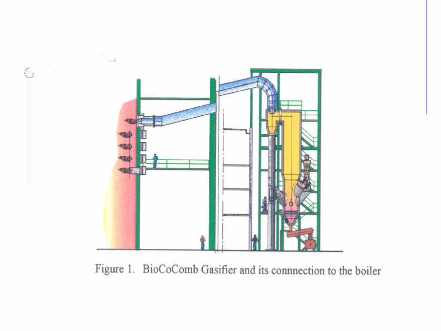
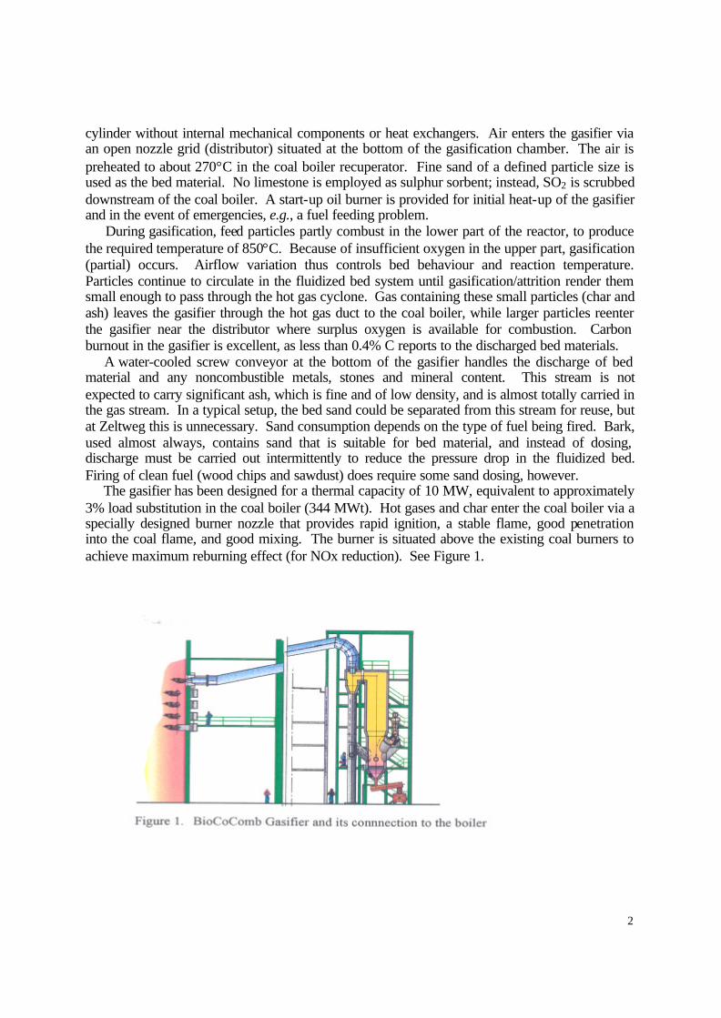
cylinder without internal mechanical components or heat exchangers. Air enters the gasifier via an open nozzle grid (distributor) situated at the bottom of the gasification chamber. The air is preheated to about 270°C in the coal boiler recuperator. Fine sand of a defined particle size is used as the bed material. No limestone is employed as sulphur sorbent; instead, SO2 is scrubbed downstream of the coal boiler. A start-up oil burner is provided for initial heat-up of the gasifier and in the event of emergencies, e.g., a fuel feeding problem. During gasification, feed particles partly combust in the lower part of the reactor, to produce the required temperature of 850°C. Because of insufficient oxygen in the upper part, gasification (partial) occurs. Airflow variation thus controls bed behaviour and reaction temperature. Particles continue to circulate in the fluidized bed system until gasification/attrition render them small enough to pass through the hot gas cyclone. Gas containing these small particles (char and ash) leaves the gasifier through the hot gas duct to the coal boiler, while larger particles reenter the gasifier near the distributor where surplus oxygen is available for combustion. Carbon burnout in the gasifier is excellent, as less than 0.4% C reports to the discharged bed materials. A water-cooled screw conveyor at the bottom of the gasifier handles the discharge of bed material and any noncombustible metals, stones and mineral content. This stream is not expected to carry significant ash, which is fine and of low density, and is almost totally carried in the gas stream. In a typical setup, the bed sand could be separated from this stream for reuse, but at Zeltweg this is unnecessary. Sand consumption depends on the type of fuel being fired. Bark, used almost always, contains sand that is suitable for bed material, and instead of dosing, discharge must be carried out intermittently to reduce the pressure drop in the fluidized bed. Firing of clean fuel (wood chips and sawdust) does require some sand dosing, however. The gasifier has been designed for a thermal capacity of 10 MW, equivalent to approximately 3% load substitution in the coal boiler (344 MWt). Hot gases and char enter the coal boiler via a specially designed burner nozzle that provides rapid ignition, a stable flame, good penetration into the coal flame, and good mixing. The burner is situated above the existing coal burners to achieve maximum reburning effect (for NOx reduction). See Figure 1.

3
Environmental Performance With only 3% thermal substitution of coal by product gas in the coal boiler, most emissions from the boiler are substantially identical to those without substitution. Operating logs have indicated no increase in CO emissions when firing product gas, suggesting that gas burnout is very good. This is of interest because the product gas burner is atypical in that it does not have a separate supply of combustion air; rather gas is burned in the excess oxygen present in the boiler. Because the typical feedstocks contain less sulphur than does the boiler coal, a minimal overall SO2 emissions reduction occurs. Also, depending on feedstock, there will be up to 3% reduction in reportable CO2 emissions. Of major impact, however, is the reduction in NOx as a result of the location of the gas burner in the boiler, above the coal burners. In this “reburning” mode, some of the NOx formed lower in the boiler is reduced, by a slight deficiency of oxygen, to N2. Thus to meet NOx emissions regulations, 10-15% less ammonia solution is required in the SNCR. This represents a 3x-5x increase from the 3% product gas contribution, and this multiplier effect should continue, within limits, as product gas substitution is increased. Mass and Energy Balances As stated above, a minimal substitution of approximately 3% of coal input on a thermal basis (5-13 MWt product gas vs a total of 344 MWt entering the boiler) has almost no negative impact on the net output of 137 MWe. The following information is available: Table 1. Zeltweg Plant Data Coal Biofuel Thermal input 330 MW 10 MW Origin Polish coal Wood chips, bark, sawdust Fuel consumption 47 t/h 2-4 t/h Lower heating value 27 MJ/kg 2-5 MJ/Nm3 (gas) Internal consumption 7 kW/MWt 14 kW/MWt Unconverted carbon to boiler 10 mol% Particle size of char dust to boiler 200 µm Air consumption 3.7 Nm3/h In addition, the following information was provided by VERBUND: Input: Biomass - 10 MWt; Coal - 330 MWt Output: 127 MWe (net to grid) Losses: Gasifier/product gas duct radiation - 0.124 MWt; Boiler - 203 MWt (flue gas, ash, radiation, etc.); Internal consumption - 10 MWe Efficiency: 127 MWe/340 MWt = 37.4% Capital, Operating and Maintenance Costs Total cost of the BioCoComb project was 5.1 M€. This amount includes engineering, biomass/waste storage, conveying system, feedstock preparation, gasifier, connection to the coal boiler, commissioning and test monitoring. Of this amount, EU THERMIE contributed 1.3 M€, about 25% of the total. It has been estimated that replication of the plant at the same scale (10 MWt) would now cost 3.7 M€ for preparation of the technical specifications, tenders, erection and commissioning. At 40% electrical efficiency (LHV basis), this is equivalent to a capital cost

4
of 925 €/kWe, quite high due to the relatively small scale. Several studies have been undertaken to estimate the cost of larger-scale plants. One detailed study by Austrian Energy for a 50 MWt plant follows, based on the following assumptions:
• Plant life: 10 years • Interest rate: 6%/a • Power plant efficiency: 40% (LHV basis) • Annual operation: 8 000 h • Annual maintenance: 1.5% of investment cost • Ash disposal cost: 75 €/t • Fuel: biomass blend at 40% moisture • Operating labour: 1 person per shift
The estimated investment cost was calculated as 400-500 €/kWe, equivalent to 9 M€ for 20 MWe. Austrian Energy states that, from experience at Zeltweg, the power plant personnel can operate the gasification plant without additional manpower. Electricity production costs depend on the feedstock price. If feedstock is waste at zero cost, electricity can be produced for less than 0.02 €/kWh. This rises to 0.047 €/kWh if feedstock is purchased for 0.014 €/kWh. A 100 MWt plant is expected to cost 10-14.5 M€, equivalent to a specific investment of 250-360 €/kWe. This illustrates the economies of scale. However, care must be taken when extending this analysis to larger-capacity plants, as sufficient feedstock must be available locally to avoid high transportation costs. Also, a suitably-sized boiler must be available, as a coal substitution much greater than 10-15% might adversely affect efficiency and boiler operation. Averaged additional operating and maintenance costs of the complete plant at Zeltweg to the end of 2000 were 17 €/h at a standard load of 10 MWt. This figure is high, but includes remedying the many system trips that occurred prior to modifications. In the absence of trips, maintenance costs were near zero, including only control, cleaning and lubricating. However, this might not be representative, considering the relatively low operating hours. Unfortunately, the main boiler at Zeltweg has been shut down since April 2001, because electricity generation at the plant is too expensive (peaking plant) and there is an overcapacity in the area. However, we have been assured that gasifier operation played no part in the decision. LAHDEN LÄMPÖVOIMA GASIFIER, LAHTI, FINLAND [2] Kymijärvi Power Station
The Kymijärvi power plant was originally commissioned in 1976 as a heavy oil- fired unit. In 1982 the unit was modified for pulverized coal firing. The boiler is a once-through Benson-type unit. Steam production is 125 kg/s at 540ºC/170 bar and 540ºC/40 bar, and the plant produces district heat for the city of Lahti and electric power for the owners. Maximum output is 167 MWe/240 MWt. The unit operates about 7 000 h/a, and is usually shut down in the summer when demand is low. In spring and autumn the plant is operated at low capacity using natural gas as the main fuel. In 1986 a gas turbine/generator set was installed, producing a maximum of 49 MWe at an outside temperature of -25ºC. Exhaust heat from this unit is used via a heat recovery boiler to preheat the boiler feed water. In summer, when the main boiler does not operate, turbine exhaust heat is transferred from the heat recovery boiler into district heating water through a separate district heat exchanger. The boiler uses about 1 200 GWh/a (180 000 t/a) of coal and about 800 GWh/a of natural gas. The boiler is equipped with an electrostatic

5
precipitator, but has no sulphur removal capability; however, the sulphur content of the coal used varies between only 0.3 to 0.5%. Flue gas recirculation/staged combustion is provided to lower NOx emissions. Circulating Fluidized Bed Gasifier
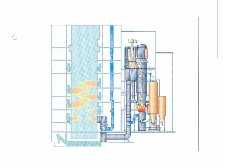
The gasifier concept employed at Lahti is quite simple. The Foster Wheeler circulating fluidized bed gasification system consists of a steel reactor, a uniflow cyclone and a return pipe, all refractory lined. Preheated gasification air, blown with a high-pressure air fan, enters the gasifier vessel at the bottom via an air distribution grid. Velocity of this air is sufficient to fluidize solid particles making up the bed. The bed expands and individual particles move rapidly, some conveyed out of the reactor into the uniflow cyclone. In the uniflow cyclone, gas and circulating solids flow downwards, with solids flowing down the return pipe, and gases going into the air preheater. Under normal operation, the fuel feed rate defines the capacity of the gasifier, while the air feed rate controls the gasifier temperature. Fuel is fed to the gasifier above the air distribution grid. This fuel is less than 5 cm in major dimension, and typically contains 20-60% moisture, 40-80% combustibles, and 1-2% ash. Typically, the gasifier operating temperature is in the range of 800ºC-1000ºC, dependent on the fuel. As fuel particles enter the gasifier, rapid drying takes place, and the primary phase of reaction—pyrolysis—occurs. Pyrolysis involves driving off volatiles and conversion of fuel particles into gas, char and tars. Some of the char falls to the bottom of the bed, where it is combusted, generating CO, CO2 and heat. These products percolate up the reactor, where secondary reactions occur—heterogeneous (char and gas) and homogeneous (gas only) reactions. These reactions result in production of a combustible product gas that enters the uniflow cyclone, and exits with only a small percentage of fine dust. Solids (mainly char) are separated in the cyclone and return to the gasifier bed near the bottom. Char combustion in the oxygen-rich fluidizing air stream produces heat required for pyrolysis and the heterogeneous and homogeneous reactions. Coarse ash accumulates at the bottom of the gasifier and is removed with a water-cooled bottom ash screw. The produced combustible gas enters a heat exchanger, lowering its temperature somewhat while preheating the fluidization air. The gas is then transported through a duct to two burners located below the coal burners in the main boiler. These burners are of a unique design developed through pilot-scale combustion tests and CFD modelling. Originally, it was envisioned that the burners would be placed above the coal burners, in the reburning mode, to control NOx; however, pilot testing showed that maximum heat and residence time (for impurity destruction) were produced with the gas burners below the coal burners. Figures 2-3 illustrate the gasifier and its connection to the boiler. Environmental Performance Table 2 summarizes the changes in environmental emissions from the main boiler at Lahti as a result of cofiring gas produced in the gasifier. The fact that CO emissions do not change indicates that there has been no degradation in combustion caused by cofiring the produced gas. Reductions in NOx and particulates can be attributed to moisture in the product gas. Moisture content slightly lowers the flame temperature in the boiler, reducing NOx while moisture in flue gas enhances performance of the electrostatic precipitator, reducing particulates emissions. Other changes result from increases (e.g., Cl) or decreases (e.g., S) of particular elements in the biomass/waste feedstock compared to the coal/natural gas used.

6
Figure 2. Cross-section of Lahti Gasifier Figure 3. Gasifier Connection to Lahti Boiler Table 2. Effect of the Gasifier on Main Boiler Emissions Emission Change Caused by Gasifier NOx Decrease by 10 mg/MJ (5-10%) [current limit - 240 mg/MJ] SOx Decrease by 20-25 mg/MJ [current limit - 240 mg/MJ] HCl Increase by 5 mg/MJ (base level low) CO No change Particulates Decrease by 15 mg/Nm3 Heavy metals Slight increase in some elements (base level low) Dioxins/furans No change PAHs No change Benzenes No change Phenols No change
Table 3 lists typical trace pollutant concentrations in the product gas when gasifying non-contaminated feedstocks. Contaminated fuels generally increase concentrations of ammonia, hydrogen cyanide and alkalis. For example, gasification of gluelam can increase the ammonia level to 3 000-5 000 mg/m3, HCN to 200-300 mg/m3 and total alkaline content to 0.3 ppmw.

7
Table 3. Typical Trace Pollutant Concentrations in Product Gas Gas Component Concentration
Range (mg/m3, dry) NH3 800-1 000 HCN 25-45 HCl 30-90 H2S 50-80 benzene 7-12 tars 7-12 alkalis <0.1 particulates 6-10
Bottom ash from the gasifier consists mainly of bed sand and limestone plus small amounts of metal chunks and concrete, etc. C content is typically less than 0.5% and chlorine is negligible. The ash also contains trace amounts of certain heavy metals; however, leachability is low. Gasifier ash makes up only a small proportion (3-5%) of total main boiler ash and, therefore, has little effect on quality. Unburned carbon and alkali levels are unchanged, but some heavy metal levels are increased slightly, depending on the type of feedstock. For example, zinc content increases when shredded tires are gasified. No changes in trace organics, such as dioxins, have been detected. Leachability test results were satisfactory, and the plant is permitted to market boiler ash as it did prior to addition of the gasifier. Energy Balance Efficiency of biomass/waste conversion to electricity is very nearly equivalent to that of the coal-fired unit itself. Based on a 15% fuel substitution by waste/biomass gas, it has been reported that net thermal efficiency for electricity production was reduced only from 31.3% to 31.1% and, for district heating, from 49.9% to 49.4% (on a HHV basis). One reason this occurs (despite the increased product gas moisture content and flue gas nitrogen content) is increased flame radiation in the furnace, and an improvement in the effectiveness of the convective heating surfaces through the back passes of the boiler and the superheater. Other explanations are, of course, possible. During a site visit, the following operating data were recorded for the gasifier: Input: 5.09 kg/s feed at 10.3 MJ/kg and 32.8% moisture (52.4 MWt)
3.45 Nm3/s air at 365ºC (heat-exchanged with product gas) Output: 19.2 Nm3/s product gas at 2.48 MJ/Nm3, 6 mbar and 810ºC (47.6 MWt) Product gas enters the boiler, in equal streams, through two bottom burners at 712ºC, after heat-exchange with the input air stream. This gas has the following composition:
• CO – 9.6% • CO2 – 12.3% • CH4 – 3.3% • H2 – 6.7% • H2O – 35.0% • Balance N2

8
The overall energy balance (52.4/47.6) is 90.8%. The operator reported that the usual gasification efficiency is approximately 92%. Capital, Operating and Maintenance Costs Total capital cost of the Lahti gasification project was about 12 M€. This figure includes fuel preparation, civil works, the gasifier, instrumentation and control, electrification, and modifications to the main boiler. Of this amount, 3 M€ (25%) was received under the EU THERMIE Program. It has been reported that Foster Wheeler would charge a higher price for a second unit. This would suggest that FW had a vested interest in seeing the first-of-a-kind plant succeed both technically and economically. A number of studies, comparing projections for plant costs and other factors for different cofiring options, have been undertaken. One of the more interesting studies is presented below. Table 4 compares capital and operating cost projections for a 20 MWe biomass plant. In this analysis, the following assumptions have been made:
• Cost of capital – 10.3% • Cost of biomass – zero • Operating cost – 0.36 M€/a • Maintenance cost – 2.5% of investment cost/a • Overhead – 40% of O & M costs • Coal cost – 50 €/t • O & M and depreciation of existing coal- fired plant – 0.018 €/kWh • Operation – 7 500 h/a
Table 4. Capital and Operating Costs for 20 MWe Biomass Plant
Concept Specific Investment (€/kWe)
Total Cost (M€)
Annual Cost (M€/a)
Electricity Cost (€/kWh)
Direct cofiring 680 14 0.45 0.021 Upstream gasification 1270 25 1.7 0.029 Upstream combustion (steam-side integration)
1360 27 1.8 0.030
Direct cofiring (if feasible) is the cheapest option, with upstream gasification rating second. Note in Table 4 that all cost projections are based on economic factors and estimates specific to the study authors, and are inserted here to represent trends rather than firm quotes. For the same 20 MWe biomass plant as outlined in Table 4, the following capital, operating and maintenance breakdown has been developed (M€/a, unless otherwise indicated):
• Capital charge – 2.7 • Personnel – 0.36 • Maintenance – 0.68 • Overhead – 0.41 • O & M sub-total – 1.5 • Biomass – 0.0 • Avoided coal – (2.5)
9
• Fuel sub-total – (2.5) • Total costs – 1.7 • Electricity cost (gasifier contribution) – 0.011 €/kWh • Electricity cost (coal boiler contribution) – 0.018 €/kWh • Total electricity cost – 0.029 €/kWh
At Lahti presently, fuel costs depend on the type and quality. Forest residue is purchased for 7 €/MWh (LHV), while recovered energy fuel (REF) costs 2-3 €/MWh. Feedstocks are tested for chlorine content, and payment is on a sliding scale, with a tipping fee (also varying) applicable when chlorine content exceeds 0.5%. Coal currently consumed at the plant costs about 12 €/MWh. Four employees currently operate the plant. With a modern computer control system, three employees would suffice. One operator is in charge of the gasifier and boiler, and sits in a combined control room. Thus with no dedicated personnel and fuel cost savings, operating costs approach zero. GREVE IN CHIANTI, ITALY, RDF PELLET GASIFIER PROJECT Circulating Fluidized Bed Gasifiers
The Greve plant is equipped with two 15 MWt Termiska Processer (TPS) CFB gasifiers, each with a capacity of 100 t/d of RDF pellets. The TPS technology uses a starved-air gasification process in a combined bubbling and circulating fluidized bed reactor, operating at about 850°C (below the ash melting point) and slightly above atmospheric pressure. Each gasifier is composed of a cylindrical riser, a U-beam conduit for coarse solids separation (by impingement), and a cyclone for finer solids separation. Solids are recycled to the bottom of the bed via return legs. All parts are internally lined with refractory to minimize thermal losses and to ensure isothermal conditions are maintained.
Air is used as the oxidizing agent, and silica and/or dolomite sand of 0.3-0.8 mm size is used as the bed material. The bottom section of the bed operates in the bubbling (dense) mode. Primary air is injected upward through the distributor at the bottom of the bed. The air injection rate and internal dimensions are such that gas velocity is lower here, compared to the upper part of the riser. Here, operating temperatures are in the range of 700-800°C. RDF, fed in pelletized form by means of a screw conveyor, falls by gravity and is distributed across the dense bed, where the volatiles are released and some fragmentation occurs. Residence time for the larger particles can be quite long, while the finer particles (fragments) are entrained with the sand, and slowly rise to the level where secondary air is injected. This is the boundary between the bubbling and fast circulating bed, and the new influx of air, heat release and particle size reduction increase gas velocity, improving gas/solid mixing. Partial combustion of gaseous species occurs here, increasing the temperature to about 850°C.
This bed expansion causes solid particles to reach the top of the riser and enter the U-beam chamber and cyclone. Separated particles are recirculated to the bubbling bed by means of the return legs, where nitrogen is used as a fluidizing agent to prevent combustion of the hot, ignitable char. Coarse particles from the U-beam chamber are completely recycled; some fine particles from the cyclone are bled off to avoid fine particle enrichment in the bed that would eventually decrease cyclone performance. Bottom ash is discharged by gravity, cooled and conveyed to storage for disposal. Raw gas leaving the cyclone is fed to the combustor/boiler.

10
Greve in Chianti Combustor/Boiler The combustor/boiler was purpose-built to accept produced gas from the gasifiers, unlike the
Lahti and Zeltweg plants at which the gasifiers were add-ons to existing coal- fired boilers. Design of the boiler had already been undertaken before TPS got involved in the project. The primary combustion chamber is refractory lined and operates adiabatically. At the top of this chamber, a downward-facing, dual- fluid burner is positioned, consisting of ten raw gas injectors arranged axially around the air injector. The gas injectors are angled to the axis to impart swirl to ensure mixing. The burner operates at high excess oxygen, which is adjusted by the control system to maintain the flue gas temperature at 1050°C. Natural gas is used as an auxiliary fuel.
The post-combustion chamber is designed as determined by law (DM 503/97) to provide 6% excess oxygen in the flue gas, and a residence time greater than two seconds at a minimum temperature of 850°C (for dioxins/furans destruction). Auxiliary burners (natural gas) and secondary air ports are provided to ensure that temperature restrictions are met. Ammonia (NH4OH) or urea (NH2CONH2) is injected directly into the post-combustion chamber flue gases to reduce nitrogen oxides (NOx) emissions through selective noncatalytic reduction (SNCR).
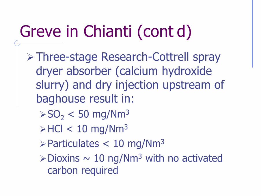
Exhaust gases enter the radiation section of the boiler, reaching the superheater at a temperature of 650°C, then pass through the convective bank and the economizer, leaving the boiler at 200°C. Superheated steam is generated in the boiler at 380°C and 42 bar, with a design mass flow of 18 t/h to the 6.7 MWe condensing steam turbine. (Note that the original plan was to eventually build a second boiler to fully load this steam turbine.) Figure 4 shows the process scheme of the plant.
Figure 4. Process Scheme of Greve in Chianti RDF Gasification Plant, Italy

11
Environmental Performance Environmental regulations in force at the time of construction stipulated that sulphur dioxide
(SO2) emissions must be reduced to less than 50 mg/Nm3, while HCl emissions could be no more than 10 mg/Nm3, both measured at 11% oxygen. To achieve this, a 1-3% (by weight) slurry of hydrated lime (calcium hydroxide, Ca(OH)2) is prepared and injected cocurrently into the flue gas exiting the economizer in a three-stage Research-Cottrell spray dryer absorber. The residence time is sufficient to allow SO2 and HCl to partially react with the slurry. Downstream of the spray dryer and upstream of a fabric filter, more lime is injected, this time dry. In-duct reaction, coupled with further reaction as the flue gases pass through the sorbent in the filter cake on the bag surface, are sufficient to meet the regulated limits. The baghouse also removes fine particulates not captured by the cyclone. As previously stated above, dioxins/furans are suppressed in the post-combustion chamber of the boiler, as is NOx (via SNCR).
Tables 5 and 6 present air emissions data, as measured in stack testing at Greve. As is obvious from the numbers, the plant is capable of meeting all EU regulations and US EPA New Source Performance Standards (NSPS). Wastewater is produced in the scrubber system, and blowdown streams are generated by the boiler and cooling tower. Pilot test data suggest that these wastewater streams can be treated adequately in a biological system or with activated carbon filters.
Table 5. Air Emissions Data—Greve in Chianti Plant
Measured Emissions Rates Greve Regulatory Limits Pollutant 11% O2 7% O2 11% O2 7% O2 CO, mg/Nm3 2.5-5 1.8-3.6 50 35 Particulates, mg/Nm3 3-7 2-5 10 7 HCl, mg/Nm3 0.5-2 0.4-1.4 30 21 HF + HBr, mg/Nm3 < 0.1 < 0.1 2 1.4 SO2, mg/Nm3 5-15 3.6-10 100 71 Heavy Metals, mg/Nm3 2.2 1.6 * * PCBs, ìg/Nm3 0.163 0.116 100 < 100 NOx, mg/Nm3 200-300 140-214 300 214 PCDD/PCDF, ng/Nm3 13.1 9.3 2 860 2 040 *See Table 6
Table 6. Heavy Metals Emissions Data—Greve in Chianti Plant
Metal Measured Value, mg/Nm3 Italian Regulatory Limit, mg/Nm3 Lead (Pb) 0.005 (maximum) 3 Cadmium (Cd) < 0.0004 0.1 Mercury (Hg) 0.008-0.05 0.1 Mass and Energy Balances
Since commissioning in 1993, the plant has operated for 5 000 h (in its original configuration), generating electricity for 4 500 h (production of 6 200 MWh). In addition, about 4 million Nm3 of cooled gas was supplied to the cement plant. Gasifier conversion efficiency has varied between 85% and 95%, on a throughput of 2-3.9 t/h of RDF pellets. Various sources

12
have placed the overall electrical efficiency of the Greve in Chianti plant, as it existed in 1997, between 18% and 20%. This was due to a number of problems that resulted in an expensive retrofit (addition of a second boiler and gas cleaning equipment). Because communication with the plant was difficult after the renovations, no new data are available. Instead, mass and energy balances are presented for a high-efficiency combined cycle TPS system based on the Greve RDF pellets as feedstock, and TPS’s extensive pilot-scale test results. In a combined cycle, the cleaned produced gas from the gasifier is combusted in a gas turbine producing electricity, and hot combustion gases from the gas turbine’s exhaust then flow through a heat recovery steam generator (HRSG) to produce steam that generates more electricity in a steam turbine/generator. Thus, feed of 387 t/d of RDF produces 25.7 MWe from the gas turbine and a further 17.0 MWe from the steam turbine. Power requirements include 7.3 MWe to compress the clean produced gas to be fed into the gas turbine, and a further 1.7 MWe needed for other equipment. This yields net power output of 33.7 MWe, and a remarkable efficiency of 39% on a higher heating value basis. Of course, this value must be reduced by the energy required to reduce the mass of the original MSW by 30% and pelletize the resulting RDF. (This value has not been reported in the available literature.)
Note that additional cleanup equipment—a dolomite catalytic tar cracker, fabric filter baghouse, wet scrubber and H2S removal—are required because the gas turbine has very strict restrictions on particulate matter, alkalis, sulphur compounds, etc. On the other hand, this will ensure that plant emissions levels, e.g., sulphur, NOx and particulates, mercury and dioxins, will be extremely low, capable of meeting present and future regulations. Capital, Operating and Maintenance Costs
Capital cost of the original plant configuration was US$20 million (approximately M€20). The added cost of the second boiler and advanced gas cleanup system was M€9.7. For a fully loaded steam turbine/generator (6.7 MWe), and assuming 5% plant auxiliary power requirement (0.335 MWe) for net electrical output of 6.365 MWe, this is equivalent to a specific capital investment of: 29 700 000/(6 700 – 335) = €4 666/kW (approximately US$4 666/kW). This is a very high figure; however, there are two mitigating considerations. First, if the initial boiler(s) had been designed and sized correctly, and if minimal gas cleaning had been added originally, the total cost would have been less than the eventual cost of what has turned out to be a patch job. Second, the cost essentially includes a spare gasifier, which will be necessary to fully load a gas turbine/steam turbine combined cycle configuration, should this direction be pursued in the future.
As operating and maintenance costs for the renovated Greve in Chianti plant are unavailable, two cost estimates for TPS combined cycle plants are instead presented here.
The first estimate is from TPS, for a plant consisting of two CFB gasification systems, and a combined cycle (gas and steam turbines). Capacity of this plant is 1 200 t/d of unpelletized RDF (from 1 600 t/d of MSW), and gross electricity generation is 74.5 MWe. Fuel preparation requires 1.4 MWe, while auxiliary power requirements (mainly to compress the gas feed for the gas turbine) use another 12.4 MWe, leaving a net output of 60.7 MWe. Capital cost of this plant (1996 US dollars) is $170.7 million, for a specific capital investment of $2 812/kW. Annual gross O&M is $35.6 million, and electricity sales (at $0.04/kWh) generate $16.3 million annually. Net O&M of $19.3 million translates to a net waste disposal cost of $38.91/t of MSW.
The second study comes from the US National Renewable Energy Laboratories (NREL) for a plant at the Weyerhauser Mill in New Bern, NC. In this feasibility study, the TPS-designed

13
cogeneration, combined cycle plant would gasify 63.7 t/h of wood wastes to produce 33.8 MWe net and 98 MWt of high- and low-pressure steam for use in the plant. Capital cost of this plant, as a retrofit, is US$ 102.1 million (1995 US dollars), yielding a specific capital investment (electricity only) of US$3 020/kW. Total annual O&M costs are US$4.69 million, for a gross waste disposal cost of US$9.35/t. (Note that this figure is based on 90% plant annual capacity factor, and does not include credit for the value of generated electricity or steam).
NREL has also estimated the cost of larger greenfield plants (without cogeneration) to examine the economies of scale. For a 59 MWe plant, specific capital investment was US$1 750/kW, and net electricity generation efficiency was calculated as 30% (HHV basis). A plant producing 100 MWe could be built for US$1 535/kW. While these figures look good on paper, a plant generating 100 MWe would require more than 1.5 million t/a of wood waste. At these quantities, the cost of acquiring and transporting waste fuel would soon render the plant uneconomical to operate. CONCLUSIONS
Gasification in fluidized bed equipment is an excellent means of recovering energy from waste both economically and at high efficiency. While Zeltweg is now closed and Greve in Chianti has had boiler problems, gasifiers in the three cases studied have performed flawlessly. When operated as a gas generator to feed an existing coal boiler, investment costs can be as low as US$600/kW; O&M costs as low as US$4/t of feed; and electricity generation efficiency as high as 37% (dependent on the boiler). This represents a cost-effective opportunity for the waste and utility sectors, providing mutual benefits (reduced feedstock costs, reduced landfill requirements and reduced reportable specific carbon dioxide emissions). REFERENCES 1. Granatstein, D.L., “Case Study On BioCoComb Biomass Gasification Project, Zeltweg
Power Station, Austria”, IEA Bioenergy Task 36 Report, September 2002. 2. Granatstein, D.L., “Case Study On Lahden Lämpövoima Gasification Project, Kymijärvi
Power Station, Lahti, Finland”, IEA Bioenergy Task 36 Report, November 2002. 3. Granatstein, D.L., “Case Study on Waste-fuelled Gasification Project, Greve in Chianti,
Italy”, IEA Bioenergy Task 36 Report, August 2003.