flue gas desulfurization (acid gas removal) systems · flue gas desulfurization (acid gas removal)...
TRANSCRIPT
2.0-7/98 9-1
Lesson 9 Flue Gas Desulfurization (Acid Gas Removal) Systems
Goal To familiarize you with the operation of flue gas desulfurization (FGD) systems that use a scrubbing liquid to absorb SO2 present in the exhaust gas stream.
Objectives At the end of this lesson, you will be able to do the following:
1. Describe how the following six operating variables affect wet scrubber operation in FGD systems:
• Liquid-to-gas ratio
• pH
• Gas velocity/residence time
• Gas distribution system
• Scrubber design
• Turndown ability
2. Briefly describe four FGD wet scrubbing processes
3. Identify operating problems associated with each FGD process above
4. Identify some of the various scrubber designs and typical operating conditions associated with FGD processes
Introduction
The previous lessons describe various scrubber designs that control emissions of gaseous and particulate pollutants. This lesson discusses a major application for scrubbers in air pollution control: flue gas desulfurization (FGD), which is one of the largest markets for scrubbing systems (in terms of money spent). The term flue gas desulfurization has traditionally referred to wet scrubbers that remove sulfur dioxide (SO2) emissions from large electric utility boilers (mainly coal combustion). However, because of the requirement to control acid
Lesson 9 ___________________________________________________________________________________
9-2 2.0-7/98
emissions from industrial boilers and incinerators and the evolution of different types of acid control systems, the terms FGD, acid gas or acid rain control are used interchangeably to categorize a wide variety of control system designs. FGD systems are also used to reduce SO2 emissions from process plants such as smelters, acid plants, refineries, and pulp and paper mills.
FGD systems can be categorized as dry or wet. In Lesson 7, you learned about dry scrubbing systems that control SO2 and other acid gases from utility and industrial boilers and incinerators. This lesson focuses on the traditional, wet FGD systems that have been installed on operating plants. This lesson will also briefly cover some of the emerging technologies (both wet or dry) that are being developed for FGD (acid rain) control.
In wet FGD scrubbing systems, the scrubbing liquid contains an alkali reagent to enhance the absorption of SO2 and other acid gases. More than a dozen different reagents have been used, with lime and limestone being the most popular. Sodium-based solutions (sometimes referred to as clear solutions) provide better SO2 solubility and less scaling problems than lime or limestone. However, sodium reagents are much more expensive.
Wet FGD scrubbers can further be classified as nonregenerable or regenerable. Nonregenerable processes, also called throwaway processes, produce a sludge waste that must be disposed of properly. It should be noted that in throwaway or nonregenerable processes the scrubbing liquid can still be recycled or regenerated; however, no useful product is obtained from the eventual sludge. Regenerable processes produce a product from the sludge that may be sold to partially offset the cost of operating the FGD system. Regenerated products include elemental sulfur, sulfuric acid and gypsum. Based on the recent capacities listed in Table 9-1, approximately 91% of FGD processes are nonregenerable, or throwaway. The throwaway processes are simpler and presently more economical than those that recover and sell products. Also, Table 9-1 shows that approximately 78% of the FGD systems represented are wet systems using lime or limestone as a reagent.

Flue Gas Desulfurization (Acid Gas Removal) Systems ___________________________________________________________________________________
2.0-7/98 9-3
Table 9-1. Summary of FGD systems by process (percentage of total Megawatts)
Process
By-product
Percent of total MW
(as of 12/89)
Throwaway product
Wet scrubbing
Dual alkali 3.4% Lime 16.3 Lime/alkaline fly ash 7.0 Limestone 48.2 Limestone/alkaline fly ash 2.4 Sodium carbonate 4.0
Spray drying
Lime 8.8 Sodium carbonate 0 Reagent type not selected 0.7
Dry injection
Lime 0.2 Sodium carbonate 0 Reagent type not selected 0
Process not selected 0
Saleable product
Wet scrubbing
Lime Metals/fly ash/other < 0.1 Limestone Gypsum 4.1 Magnesium oxide Sulfuric acid 1.4 Wellman Lord Sulfuric acid 3.1
Spray drying
Lime Dry scrubber waste 0
Process undecided 0
Total 100.0 Source: Hance 1991.
Most FGD systems employ two stages: one for fly ash removal and the other for SO2 removal. Attempts have been made to remove both the fly ash and SO2 in one scrubbing vessel. However, these systems experienced severe maintenance problems and low simultaneous removal efficiencies. In wet scrubbing systems the flue gas normally passes

Lesson 9 ___________________________________________________________________________________
9-4 2.0-7/98
first through a fly ash removal device, either an electrostatic precipitator or a wet scrubber, and then into the SO2 absorber. However, in dry injection or spray drying operations, the SO2 is first reacted with the sorbent and then the flue gas passes through a particulate control device.
Many different types of absorbers have been used in wet FGD systems, including spray towers, venturis, plate towers, and mobile packed beds. Because of scale buildup, plugging, or erosion, which affect FGD dependability and absorber efficiency, the trend is to use simple scrubbers such as spray towers instead of more complicated ones. The configuration of the tower may be vertical or horizontal, and flue gas can flow cocurrently, countercurrently, or crosscurrently with respect to the liquid. The chief drawback of spray towers is that they require a higher liquid-to-gas ratio requirement for equivalent SO2 removal than other absorber designs (Makansi 1982).
Numerous operating variables affect the SO2 removal rate of the absorber. Most of these variables were discussed in previous lessons; however, some are unique to FGD absorbers. The following list contains some of the important parameters affecting the operation of an FGD scrubber (Ponder et al. 1979 and Leivo 1978):
Liquid-to-gas ratio - The ratio of scrubber liquid slurry to gas flow (L/G ratio). For a given set of system variables, a minimum L/G ratio is required to achieve the desired SO2 absorption, based on the solubility of SO2 in the liquid. High L/G ratios require more piping and structural design considerations, resulting in higher costs.
pH - Depending on the particular type of FGD system, pH must be kept within a certain range to ensure high solubility of SO2 and to prevent scale buildup.
Gas velocity - To minimize equipment cost, scrubbers are designed to operate at maximum practicable gas velocities, thereby minimizing vessel size. Maximum velocities are dictated by gas-liquid distribution characteristics and by the maximum allowable liquid entrainment that the mist eliminator can handle. Gas velocities may be 1.5 to 10 m/s (5 to 30 ft/sec) in tower scrubbers and more than 30 m/s (100 ft/sec) in the throat of a venturi scrubber. A common range of the gas velocity for FGD absorbers is 2.0 to 3.0 m/s (7 to 10 ft/sec). The lower the velocity is, the less the entrainment, but the more costly the scrubber will be.
Residence Time - For FGD processes using an alkali slurry for scrubbing, the system should be designed to provide adequate residence time in the absorber vessel for the SO2 to be absorbed by the alkali slurry. The main objective is to make sure that the maximum amount of alkali is utilized in the scrubber. Residence times in packed towers may be as long as 5 seconds. Residence times in venturi scrubbers are a few hundredths of a second, usually too short for high absorption efficiency of SO2 in systems using lime or limestone scrubbing slurries, unless additives or two scrubbing stages are used.
Gas distribution - Maintaining a uniform gas flow is a major problem that occurs in commercial FGD scrubbers. If the flow is not uniform, the scrubber will not operate at design efficiencies. In practice, uniform flow has been difficult to achieve. Typically, turning vanes near the scrubber inlet duct and compartmentalization have been used.
Scrubber designs - To promote maximum gas-liquid surface area and contact time, a number of scrubber designs have been used. Common ones are mobile-bed scrubbers, venturi-rod scrubbers, plate towers, packed towers, and spray towers. Countercurrent packed towers are

Flue Gas Desulfurization (Acid Gas Removal) Systems ___________________________________________________________________________________
2.0-7/98 9-5
infrequently used because they have a tendency to become plugged by collected particles or to scale when lime or limestone scrubbing slurries are used.
Turndown - The ability to operate at less than full load and to adjust to changes in boiler load. The scrubber must provide good gas-liquid distribution, sufficient residence time, and high gas-liquid interfacial area for varying gas flow rates. Some scrubbers can be turned down to 50% of design, while others must be divided into sections that can be closed off. A variable-throat venturi can be used to accommodate turndown. In a large FGD installation, individual modules can be taken out of service.
It is important to note that the above list does not imply that these are the only parameters affecting SO2 absorption efficiency. Each FGD process has a unique set of operating criteria.
In addition to the set of factors just given, the coal properties greatly affect FGD system design for boiler operations. The major coal properties affecting FGD system design and operation are (Leivo 1978):
Heating value of coal - Affects flue gas flow rate. Flow rate is generally higher for lower heating value coals, which also contribute a greater water-vapor content to the flue gas.
Moisture content - Affects the heating value (i.e. since the higher the moisture content the lower the heating value) and contributes directly to the moisture content and volume of the flue gas.
Sulfur content - The sulfur content, together with the allowable emission standards, determines the required SO2 removal efficiency, the FGD system complexity and cost, and also affects sulfite oxidation.
Ash content - May affect FGD system chemistry and increase erosion. In some cases, it may be desirable to remove fly ash upstream from the FGD system.
Chlorine content - May require high-alloy metals or linings to combat corrosion for some process equipment and could affect process chemistry or require prescrubbing.
Another important design consideration associated with wet FGD systems is that the flue gas exiting the absorber is saturated with water and still contains some SO2. (No system is 100% efficient.) Therefore, these gases are highly corrosive to any downstream equipment - i.e., fans, ducts, and stacks. Two methods that minimize corrosion are: (1) reheating the gases to above their dew point and (2) choosing construction materials and design conditions that allow equipment to withstand the corrosive conditions. The selection of a reheating method or the decision not to reheat (thereby requiring the use of special construction materials) are very controversial topics connected with FGD design (Makansi 1982). Both alternatives are expensive and must be considered on a by-site basis.
Four methods used to reheat stack gases:
1. Indirect in-line reheating - The flue gas passes through a heat exchanger that uses steam or hot water.
2. Indirect-direct reheating - Steam is used to heat air (outside the duct) and then the hot air is mixed with the scrubbed gases.

Lesson 9 ___________________________________________________________________________________
9-6 2.0-7/98
3. Direct combustion reheating - Oil or gas is burned either in the duct or in an external chamber, and the resulting hot gases are mixed with the scrubbed gases.
4. Bypass reheating - A portion of the untreated hot flue gas bypasses the scrubber and is mixed with the scrubbed gases.
None of the above methods has a clear advantage over the others (Makansi 1982). Systems using indirect in-line reheating have experienced severe corrosion and plugging problems. Indirect-direct and direct combustion reheating are expensive because of added fuel costs and bypass reheating is limited in the degree of reheating obtainable (due to SO2 emissions in the bypass). Because of the expense and problems associated with reheat, newer FGD designs are utilizing more plastics (fiberglass reinforced plastic) and exotic alloys instead of reheat.
This lesson will discuss four of the more popular FGD systems that are nonregenerable, calcium- and/or sodium-based systems. The process chemistry, system description, and operating experience involved in each will be presented.
To test your knowledge of the preceding section, answer the questions in Part 1 of the Review Exercise.
Nonregenerable FGD Processes
Nonregenerable FGD processes generate a sludge or waste product. The sludge must be disposed of properly in a pond or landfill. The three most common nonregenerable processes used on utility boilers in the U. S. are lime, limestone, and double-alkali. Although the double-alkali process regenerates the scrubbing reagent, it is classified as throwaway since it does not produce a saleable product and generates solids that must be disposed of in a landfill. The fourth nonregenerable process discussed here, sodium-based throwaway systems (NaOH and Na2CO3), are utilized mostly on industrial boilers.
Lime Scrubbing
Process Chemistry Lime scrubbing uses an alkaline slurry made by adding lime (CaO), usually 90% pure, to water. The alkaline slurry is sprayed in the absorber and reacts with the SO2 in the flue gas. Insoluble calcium sulfite (CaSO3) and calcium sulfate (CaSO4) salts are formed in the chemical reaction that occurs in the scrubber and are removed as sludge.
A number of reactions take place in the absorber. Before the calcium can react with the SO2, both must be broken down into their respective ions. This is accomplished by slaking (dissolving) the lime in water and then spraying the slurry into the flue gas to dissolve the SO2. Simplified reactions occur simultaneously and are illustrated below.
Flue Gas Desulfurization (Acid Gas Removal) Systems ___________________________________________________________________________________
2.0-7/98 9-7
SO2 dissociation: SO2 (gaseous) → SO2 (aqueous)
SO2 + H2O → H2SO3
H SO2 3 → → H + HSO 2H + SO+3- +
3=
Lime (CaO) dissolution: CaO(solid) + H2O → Ca(OH)2 (aqueous)
Ca(OH2) → Ca++ + 2OH-
Now that SO2 and lime are broken into their ions ( SO3= and Ca++), the following
reaction occurs:
Ca O++ → + SO + 2H + 2OH CaSO + 2H3= + -
3 (solid) 2
In addition, the following reactions can also occur when there is excess oxygen:
SO
SO3
4
=
=
→
→
+ 1 / 2 O SO
+ Ca CaSO2 4
=
++4 (solid)
From the above relationships and assuming that the lime is 90% pure, it will take 1.1 moles of lime to remove 1 mole of SO2 gas.
System Description The equipment necessary for SO2 emission reduction comes under four operations:
1. Scrubbing or absorption - Accomplished with scrubbers, holding tanks, liquid-spray nozzles, and circulation pumps.
2. Lime handling and slurry preparation - Accomplished with lime unloading and storage equipment, lime processing and slurry preparation equipment.
3. Sludge processing - Accomplished with sludge clarifiers for dewatering, sludge pumps and handling equipment, and sludge solidifying equipment.
4. Flue-gas handling - Accomplished with inlet and outlet ductwork, dampers, fans, and stack gas reheaters.
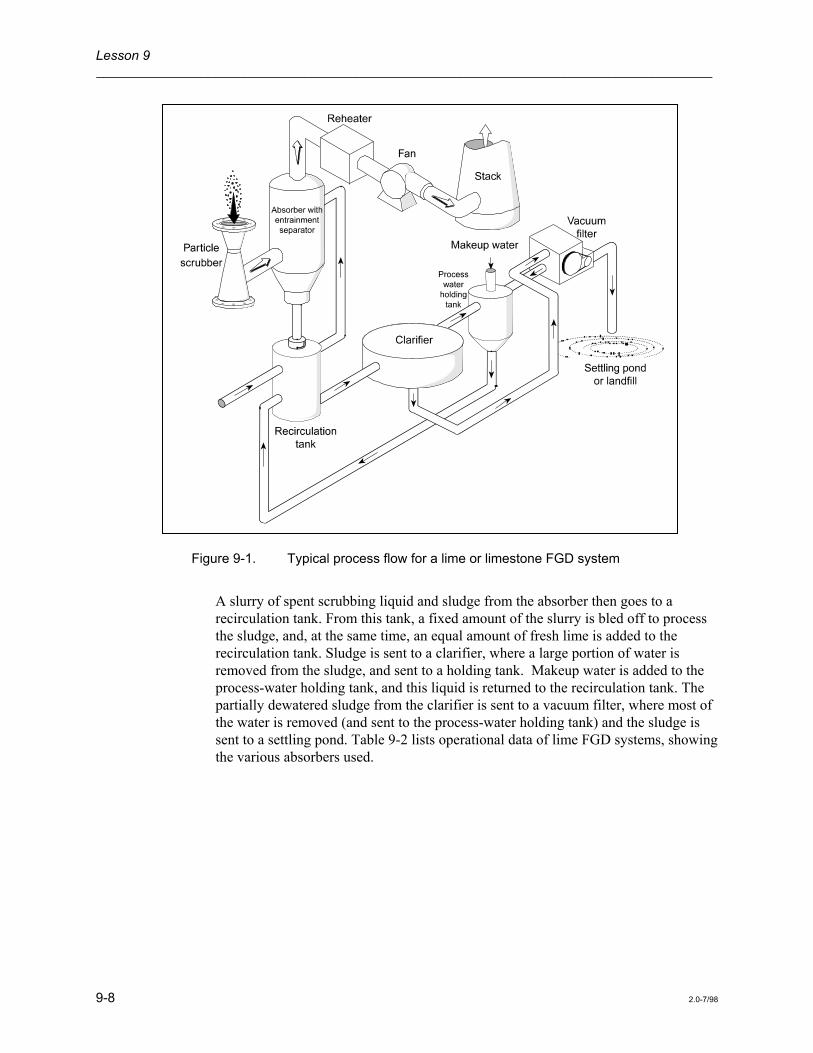
Figure 9-1 is a schematic of a typical lime FGD system. Individual FGD systems vary considerably, depending on the FGD vendor and the plant layout. ESPs or scrubbers can be used for particle removal, followed by one of various absorber designs that are effective for SO2 removal. In general, as shown in Figure 9-1, flue gas from the boiler first passes through a particulate emission removal device then into the absorber where the SO2 is removed. The gas then passes through the entrainment separator to a reheater and is finally exhausted out of the stack.
Lesson 9 ___________________________________________________________________________________
9-8 2.0-7/98
Figure 9-1. Typical process flow for a lime or limestone FGD system
A slurry of spent scrubbing liquid and sludge from the absorber then goes to a recirculation tank. From this tank, a fixed amount of the slurry is bled off to process the sludge, and, at the same time, an equal amount of fresh lime is added to the recirculation tank. Sludge is sent to a clarifier, where a large portion of water is removed from the sludge, and sent to a holding tank. Makeup water is added to the process-water holding tank, and this liquid is returned to the recirculation tank. The partially dewatered sludge from the clarifier is sent to a vacuum filter, where most of the water is removed (and sent to the process-water holding tank) and the sludge is sent to a settling pond. Table 9-2 lists operational data of lime FGD systems, showing the various absorbers used.

Flue Gas Desulfurization (Acid Gas Removal) Systems ___________________________________________________________________________________
2.0-7/98 9-9

Lesson 9 ___________________________________________________________________________________
9-10 2.0-7/98
Table 9-2. (continued) Operational data for lime FGD systems on utility boilers
Company and
MW
FGD vendor
Fly ash
%S in
SO2 absorber
No. of modules
per
L/G ratio
Pres
plant name (gross) control coal boiler L/m3 gal/1000 ft3
kPa
Kansas City Power & Light
Hawthorn #3 90 Combustion Engineering
- 0.6 Mobile bed (marbles) 2 3.5 26.0 2.7
Hawthorn #4 90 Combustion Engineering
- 0.6 Mobile bed (marbles) 2 3.5 26.0 2.7
Monongahela Power
Pleasants #1 618 B&W ESP 3.7 Sieve tray 4 7.4 55.0 1.2
Pleasants #2 618 B&W ESP 4.5 Sieve tray 4 7.4 55.0 -
Utah Power & Light
Hunter #1 400 Chemico ESP 0.6 Countercurrent spray 4 5.7 43.0 0.6
Hunter #2 400 Chemico ESP 0.6 Countercurrent spray 4 5.7 43.0 0.6
Huntingdon #1 430 Chemico ESP 0.6 Countercurrent spray 4 5.7 43.0 0.6Note: A dash (-) indicates that no data are available.

Flue Gas Desulfurization (Acid Gas Removal) Systems ___________________________________________________________________________________
2.0-7/98 9-11
Operating Experience Early lime FGD systems were plagued with many operational and maintenance problems. Scale buildup and plugging of absorber internals and associated equipment were prominent problems. However, scaling and plugging in lime FGD systems were not as severe as with other calcium-based FGD systems (EPA 1981). Scale buildup (CaSO4) on spray nozzles and entrainment separators was particularly troublesome. New spray nozzle designs and careful control of the recirculating slurry have reduced internal scrubber scaling (EPA 1975). Problems with the entrainment separators have also been reduced by careful separator design, installing adequate wash sprays, and monitoring the pressure drop across them. Additional techniques that reduce scale buildup are (Leivo 1978):
Control of pH - If a lime FGD system is operated above a pH of 8.0 to 9.0, there is a risk of sulfite scaling. Automatic control of the feed by on-line pH sensors has been successful.
Holding tank residence time - By providing retention time in the scrubber recirculation tank, the supersaturation of the liquor can be decreased before recycling to the scrubber. Typical residence times of 5 to 15 minutes have been used in some full-scale systems.
Control of suspended solids concentration - The degree of supersaturation can be minimized by keeping an adequate supply of seed crystals in the scrubber slurry. Typical levels in newer installations range from 5 to 15% suspended solids. Solids are generally controlled by regulating the slurry bleed rate.
Liquid-to-gas ratio - High liquid-to-gas ratios can reduce scaling problems because the absorber outlet slurry is more dilute, containing less calcium sulfates and calcium sulfites that cause scaling.
Another problem that has occurred concerns stack gas reheaters. Stack gas is reheated to avoid condensation on and corrosion of the ductwork and stack, and to enhance plume rise and pollutant dispersion. Reheating is accomplished by using steam coils in the stack, by using hot air supplied by auxiliary oil heaters in the stack, or by other methods previously mentioned. Some reheater failures were caused by acid attack to reheater components. Other reheaters vibrated too much, causing structural deterioration.
Corrosion of scrubber internals, fans and ductwork, and stack linings have been reduced by using special materials such as rubber- or plastic-coated steel and by carefully controlling slurry pH with monitors. Additional operation and maintenance problems and solutions are found in Lime FGD Systems Data Book, Second Edition (EPRI 1983).
To test your knowledge of the preceding section, answer the questions in Part 2 of the Review Exercise.

Lesson 9 ___________________________________________________________________________________
9-12 2.0-7/98
Limestone Scrubbing
Process Chemistry Limestone scrubbers are very similar to lime scrubbers. The use of limestone (CaCO3) instead of lime requires different feed preparation equipment and higher liquid-to-gas ratios (since limestone is less reactive than lime). Even with these differences, the processes are so similar that an FGD system can be set up to use either lime or limestone in the scrubbing liquid (See Figure 9-1).
The basic chemical reactions occurring in the limestone process are very similar to those in the lime-scrubbing process. The only difference is in the dissolution reaction that generates the calcium ion. When limestone is mixed with water, the following reaction occurs:
CaCO O 3 (solid) 2++
3- - + H Ca + HCO + OH→
The other reactions are the same as those for lime scrubbing.
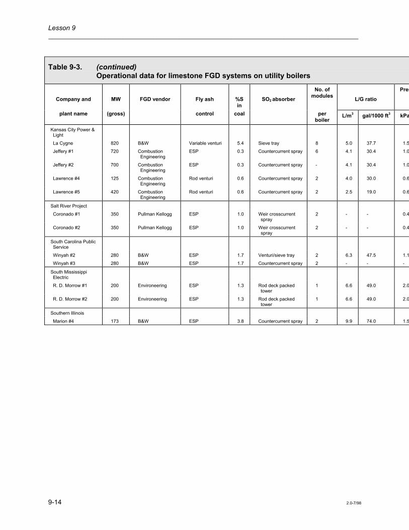
System Description The equipment necessary for SO2 absorption is the same as that for lime scrubbing, except in the slurry preparation. The limestone feed (rock) is reduced in size by crushing it in a ball mill. Limestone is sent to a size classifier. Pieces larger than 200 mesh are sent back to the ball mill for recrushing. Limestone is mixed with water in a slurry supply tank. Limestone is generally 2 to 4 times cheaper than lime, making it more popular for large FGD systems. Table 9-3 lists operations data for limestone FGD systems. Note the similarities in equipment and operating conditions to those of lime FGD systems.

Flue Gas Desulfurization (Acid Gas Removal) Systems ___________________________________________________________________________________
2.0-7/98 9-13
See Table 9-3. Operational data for limestone FGD systems on utility boilers
Table 9-3. Operational data for limestone FGD systems on utility boilers
Company and
MW
FGD vendor
Fly ash
%S in
SO2 absorber
No. of modules
L/G ratio
Pres
plant name (gross) control coal per boiler
L/m3 gal/1000 ft3 kPa
Alabama Electric
Tombigbee #2 255 Peabody ESP 1.2 Countercurrent spray 2 9.4 70.0 1.0
Tombigbee #3 255 Peabody ESP 1.2 Countercurrent spray 2 9.4 70.0 1.0
Arizona Electric Power
Apache #2 195 Research-Cottrell ESP 0.5 Spray/packed bed 2 2.8 20.6 1.5
Apache #3 195 Research-Cottrell ESP 0.5 Spray/packed bed 2 2.8 20.6 1.5
Cholla #1 119 Research-Cottrell Cyclone/venturi 0.5 Spray/packed bed 1 6.5 48.9 0.1
Cholla #2 264 Research-Cottrell Cyclone/venturi 0.5 Spray/packed bed 4 6.5 48.9 0.1
Basin Electric Power
Laramie River #1 570 Research-Cottrell ESP 0.8 Spray/packed bed 5 8.0 60.0 -
Laramie River #2 570 Research-Cottrell ESP 0.8 Spray/packed bed 5 8.0 60.0 -
Central Illinois Light
Duck Creek #1 416 Environeering ESP 3.7 Rod deck packed tower
4 6.7 50.0 2.0
Colorado Ute Electrical
Craig #1 447 Peabody ESP 0.4 Countercurrent spray 4 6.7 50.0 1.6
Craig #2 455 Peabody ESP 0.4 Countercurrent spray 4 6.7 50.0 1.6
Commonwealth Edison
Powerton 450 Air Correction Division - UOP
ESP 3.5 Mobile bed (TCA) 3 8.0 60.0 3.0
Indianapolis Power & Light
Petersburg #3 532 Air Correction Division - UOP
ESP 3.2 Mobile bed (TCA) 4 6.7 50.0 1.7
Lesson 9 ___________________________________________________________________________________
9-14 2.0-7/98
Table 9-3. (continued) Operational data for limestone FGD systems on utility boilers
Company and
MW
FGD vendor
Fly ash
%S in
SO2 absorber
No. of modules
L/G ratio
Pres
plant name (gross) control coal per boiler
L/m3 gal/1000 ft3 kPa
Kansas City Power & Light
La Cygne 820 B&W Variable venturi 5.4 Sieve tray 8 5.0 37.7 1.5
Jeffery #1 720 Combustion Engineering
ESP 0.3 Countercurrent spray 6 4.1 30.4 1.0
Jeffery #2 700 Combustion Engineering
ESP 0.3 Countercurrent spray - 4.1 30.4 1.0
Lawrence #4 125 Combustion Engineering
Rod venturi 0.6 Countercurrent spray 2 4.0 30.0 0.6
Lawrence #5 420 Combustion Engineering
Rod venturi 0.6 Countercurrent spray 2 2.5 19.0 0.6
Salt River Project
Coronado #1 350 Pullman Kellogg ESP 1.0 Weir crosscurrent spray
2 - - 0.4
Coronado #2 350 Pullman Kellogg ESP 1.0 Weir crosscurrent spray
2 - - 0.4
South Carolina Public Service
Winyah #2 280 B&W ESP 1.7 Venturi/sieve tray 2 6.3 47.5 1.1
Winyah #3 280 B&W ESP 1.7 Countercurrent spray 2 - - -
South Mississippi Electric
R. D. Morrow #1 200 Environeering ESP 1.3 Rod deck packed tower
1 6.6 49.0 2.0
R. D. Morrow #2 200 Environeering ESP 1.3 Rod deck packed tower
1 6.6 49.0 2.0
Southern Illinois
Marion #4 173 B&W ESP 3.8 Countercurrent spray 2 9.9 74.0 1.5
Flue Gas Desulfurization (Acid Gas Removal) Systems ___________________________________________________________________________________
2.0-7/98 9-15
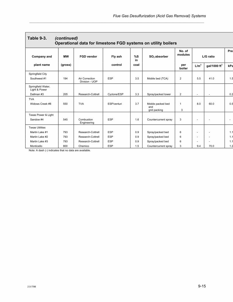
Table 9-3. (continued) Operational data for limestone FGD systems on utility boilers
Company and
MW
FGD vendor
Fly ash
%S in
SO2 absorber
No. of modules
L/G ratio
Pres
plant name (gross) control coal per boiler
L/m3 gal/1000 ft3 kPa
Springfield City
Southwest #1 194 Air Correction Division - UOP
ESP 3.5 Mobile bed (TCA) 2 5.5 41.0 1.5
Springfield Water, Light & Power
Dallman #3 205 Research-Cottrell Cyclone/ESP 3.3 Spray/packed tower 2 - - 0.2
TVA
Widows Creek #8 550 TVA ESP/venturi 3.7 Mobile packed bed and grid packing
1 3
8.0 60.0 0.5
Texas Power & Light
Sandow #4 545 Combustion Engineering
ESP 1.6 Countercurrent spray 3 - - -
Texas Utilities
Martin Lake #1 793 Research-Cottrell ESP 0.9 Spray/packed bed 6 - - 1.1
Martin Lake #2 793 Research-Cottrell ESP 0.9 Spray/packed bed 6 - - 1.1
Martin Lake #3 793 Research-Cottrell ESP 0.9 Spray/packed bed 6 - - 1.1
Monticello 800 Chemico ESP 1.5 Countercurrent spray 3 9.4 70.0 1.2Note: A dash (-) indicates that no data are available.

Lesson 9 ___________________________________________________________________________________
9-16 2.0-7/98
Operating Experience Early limestone FGD systems had scrubber operating problems similar to those of lime scrubbing systems. Plugged and clogged nozzles, scrubber internals, and mist eliminators (entrainment separators) resulted from inefficient SO2 absorption by limestone in the scrubber.
Increased absorption efficiency is achievable at high pH values since more alkali is available to dissolve the SO2 gas. However, scale buildup will occur if the scrubber is operated at very high pH values. The pH levels can be maintained by carefully controlling limestone and water feed rates. Low pH reduces removal efficiency; high pH causes scale buildup on scrubber internals.
As you can see from Tables 9-2 and 9-3, the SO2 removal efficiencies for various lime and limestone FGD installations range from 52% to 97%. These FGD systems were designed to meet existing air pollution regulations. Lime and limestone FGD systems are capable of removing SO2 with efficiencies in excess of 90%. The addition of small amounts of reagents (such as soluble magnesium) to the scrubber liquor can greatly increase SO2 removal efficiencies to as high as 99% (Devitt et al. 1978).
Another scrubber operating problem occurring in lime and limestone FGD systems is that calcium sulfite in the sludge settles and filters poorly. It can be removed from the scrubber slurry only in a semi-liquid or paste-like form. A process improvement called forced oxidation was developed by an EPA research laboratory to address this problem. In forced oxidation, air is blown into a designated section of the absorber module or into a separate reaction (oxidation) tank. The air oxidizes the calcium sulfite to calcium sulfate in the following reaction:
CaSO3 + H2O + 1/2 O2 → CaSO4 + H2O
Calcium sulfate formed by this reaction grows to a larger crystal size than calcium sulfite. As a result, calcium sulfate is easily filtered, forming a drier and more stable material that can be disposed of in a landfill or has the potential to be sold as a product to make cement, gypsum wallboard, or as a fertilizer additive.
Forced oxidation also helps control scale buildup problems on scrubber internals by removing the calcium sulfite from the slurry in the form of calcium sulfate, which is more easily filtered. This prevents calcium sulfites from oxidizing and precipitating out in the scrubber internal areas. Another method to prevent oxidation of calcium sulfite to calcium sulfate is by use of chemical inhibitors. Sulfur, magnesium and dibasic acid have all been tested and proven effective in inhibiting oxidation and thus reducing scaling in lime and limestone FGD systems.
To test your knowledge of the preceding section, answer the questions in Part 3 of the Review Exercise.

Flue Gas Desulfurization (Acid Gas Removal) Systems ___________________________________________________________________________________
2.0-7/98 9-17
Dual-Alkali Scrubbing
Dual- or double-alkali scrubbing is a third throwaway FGD process that uses a sodium-based alkali solution to remove SO2 from combustion exhaust gas. The sodium alkali solution absorbs SO2, and the spent absorbing liquor is regenerated with lime or limestone. Using both sodium- and calcium-based compounds is where the name dual or double-alkali comes from. Calcium sulfites and sulfates are precipitated and discarded as sludge. The regenerated sodium scrubbing solution is returned to the absorber loop. The dual-alkali process has reduced plugging and scaling problems in the absorber because sodium scrubbing compounds are very soluble. Dual-alkali systems are capable of 95% SO2 reduction.
Particulate matter is removed prior to SO2 scrubbing by an electrostatic precipitator or a venturi scrubber. This prevents the following: (1) fly ash erosion of the absorber internals and (2) any appreciable oxidation of the sodium solution in the absorber due to catalytic elements in the fly ash (EPA 1978).
Process Chemistry The sodium alkali solution is usually a mixture of the following compounds:
1. Sodium hydroxide (NaOH), also called caustic
2. Sodium carbonate (Na2CO3), also called soda ash
3. Sodium sulfite (Na2SO3)
The SO2 reacts with the alkaline components to primarily form sodium sulfite and sodium bisulfite (NaHSO3). The following are the main absorption reactions (EPA 1981):
2 NaOH + SO2 → Na2SO3 + H2O
NaOH + SO2 → NaHSO3
Na2CO3 + SO2 + H2O → 2NaHSO3
Na2CO3 + SO2 → Na2SO3 + CO2
Na2SO3 + SO2 + H2O → 2NaHSO3
In addition to the above reactions, some of the SO3 present may react with alkaline components to produce sodium sulfate. For example,
2NaOH + SO3 → Na2SO4 + H2O

Lesson 9 ___________________________________________________________________________________
9-18 2.0-7/98
Throughout the system, some sodium sulfite is oxidized to sulfate by:
2Na2SO3 + O2 → 2Na2SO4
After reaction in the absorber, spent scrubbing liquor is bled to a reactor tank for regeneration. Sodium bisulfite and sodium sulfate are inactive salts and do not absorb any SO2. Actually, it is the hydroxide ion ( OH− ), sulfite ion ( SO3
= ), and carbonate ion ( CO3
= ) that absorb SO2 gas. Sodium bisulfite and sodium sulfate are reacted with lime or limestone to produce a calcium sludge and a regenerated sodium solution.
2 3 3NaHSO SO O O + Ca(OH) Na + CaSO 1 / 2 H + 3 / 2 H (lime) (sludge)
2 2 3 2 2→ • ↓
Na + Ca(OH) + 1 / 2 H 2NaOH + CaSO 1 / 2 H (lime) (sludge)
2 2 2 3SO O O3 2→ • ↓
Na + Ca(OH) 2NaOH + CaSO (lime) (sludge)
2 2 4SO4 → ↓
At the present time, lime regeneration is the only process that has been used on commercial dual-alkali installations.
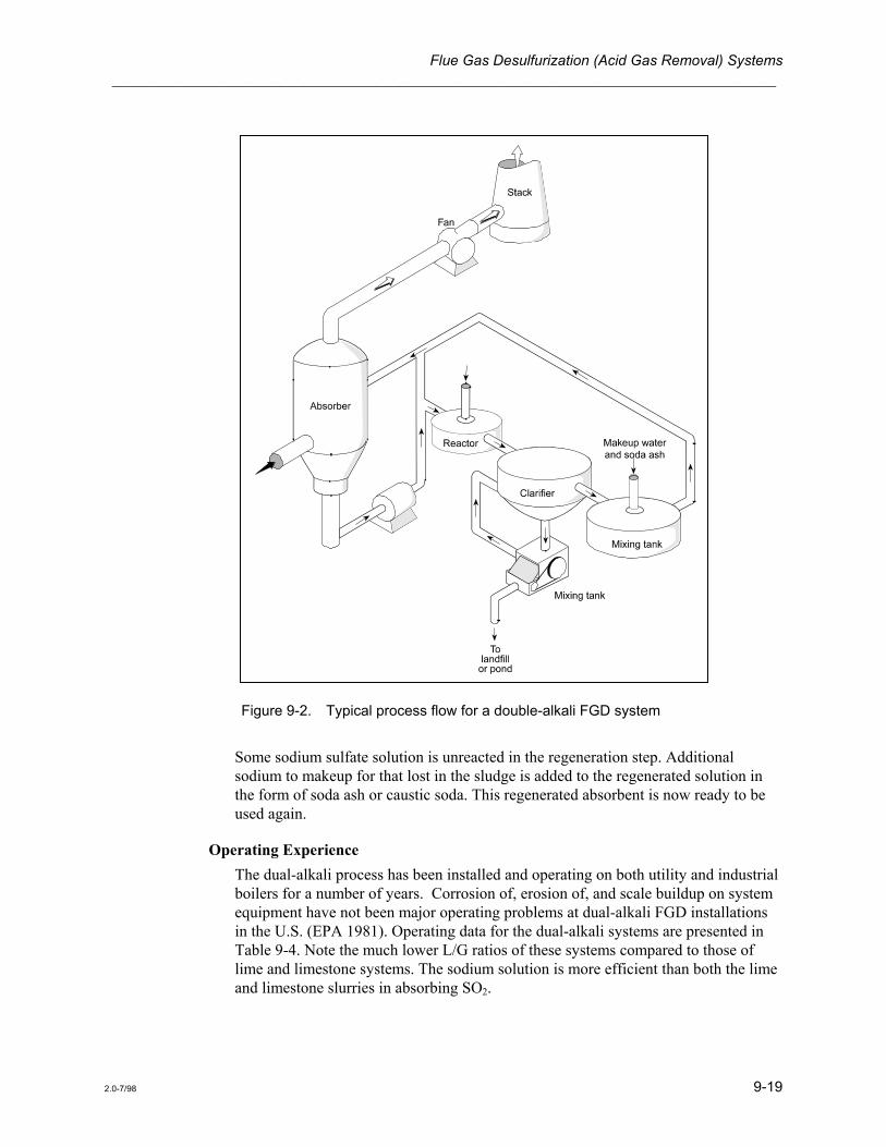
System Description The dual-alkali process uses two loops - absorption and regeneration. In the absorption loop, the sodium solution contacts the flue gas in the absorber to remove SO2. As shown in Figure 9-2, the scrubbing liquor from the bottom of the absorber is mixed with regenerated solution and sprayed in at the top of the absorber. A bleed stream from the recirculating liquid is sent to the reactor tank in the regeneration loop. The bleed stream is mixed with a lime slurry in a reactor tank, where insoluble calcium salts are formed and the absorbent is regenerated. The sludge from the reactor is then sent to a clarifier, or thickener, where the calcium sludge is drawn off the bottom, filtered, and washed with water. From the filter, the sodium solution is recycled to the clarifier, and the sludge is discarded. From the clarifier, the regenerated sodium solution is sent to a mixing tank where the sodium compounds and makeup water are added.
Flue Gas Desulfurization (Acid Gas Removal) Systems ___________________________________________________________________________________
2.0-7/98 9-19
Figure 9-2. Typical process flow for a double-alkali FGD system
Some sodium sulfate solution is unreacted in the regeneration step. Additional sodium to makeup for that lost in the sludge is added to the regenerated solution in the form of soda ash or caustic soda. This regenerated absorbent is now ready to be used again.
Operating Experience The dual-alkali process has been installed and operating on both utility and industrial boilers for a number of years. Corrosion of, erosion of, and scale buildup on system equipment have not been major operating problems at dual-alkali FGD installations in the U.S. (EPA 1981). Operating data for the dual-alkali systems are presented in Table 9-4. Note the much lower L/G ratios of these systems compared to those of lime and limestone systems. The sodium solution is more efficient than both the lime and limestone slurries in absorbing SO2.

Lesson 9 ___________________________________________________________________________________
9-20 2.0-7/98
See Table 9-4. Operational data for double-alkali FGD systems on utility and industrial boilers
Table 9-4. Operational data for double-alkali FGD systems on utility and industrial boilers
Company and
MW
FGD vendor
Fly ash
%S in
SO2 absorber
No. of
modules
L/G ratio
Pres
plant name (gross) control coal per boiler
L/m3 gal/1000 ft3 kPa
Central Illinois Public Service
Newton #1 617 Buell ESP 2.5 Mobile bed 4 1.3 10.0 1.5
Louisville Gas & Electric
Cane Run #6 299 Combustion Equipment Association
ESP 4.8 Sieve plates 2 1.3 10.0 2.5
Southern Indiana Gas & Electric
A. B. Brown #1 265 FMC ESP 3.6 Variable-throat venturi
2 1.3 10.0 2.5
Caterpillar Tractor
East Peoria, IL 105 FMC Cyclone 3.2 Venturi 4 2.2 16.0 -
Joliet, IL 34 Zurn Cyclone 3.2 Dustraxtor 2 - - -
Morton, IL 19 Zurn Cyclone 3.2 Dustraxtor 2 - - -
Mossville, IL 70 FMC Cyclone - Venturi 4 1.2 8.6 -
Firestone Tire
Pottstown, PA 4 FMC Cyclone 3.0 Venturi 1 1.3 10.0 -
General Motors
Parma, OH 64 GM Environmental Cyclone - Bubble-cap plates 4 2.6 20.0 0.9Note: A dash (-) indicates that no data are available.
Flue Gas Desulfurization (Acid Gas Removal) Systems ___________________________________________________________________________________
2.0-7/98 9-21
Some operating problems include regenerating scrubbing liquor and controlling the solids content of the sludge. Sodium sulfate, one of the compounds in the spent scrubbing liquor, is difficult to regenerate because it does not react efficiently with hydrated lime in the presence of sodium sulfite (Leivo 1978). Process conditions must be carefully controlled to adjust for the amounts of sodium sulfate and sodium sulfite that are formed in the spent scrubbing liquid. Another problem occurring in dual-alkali systems is that the solids content of the sludge can vary greatly, causing problems in handling and stabilizing the sludge for final disposal (Makansi 1982).
To test your knowledge of the preceding section, answer the questions in Part 4 of the Review Exercise.
Sodium-Based Once-Through Scrubbing
Sodium-based once-through (throwaway) scrubbing systems are installed on a number of industrial boilers. These systems use a clear liquid absorbent of either sodium carbonate, sodium hydroxide, or sodium bicarbonate. According to Makansi (1982), sodium-based systems are favored for treating flue gas from industrial boilers for the following reasons:
• Sodium alkali is the most efficient of the commercial reagents in removing SO2, and the chemistry is relatively simple.
• They are soluble systems as opposed to slurry systems making for scale-free operation and fewer components.
• Such systems can handle the wider variations in flue-gas composition resulting from the burning of many different fuels by industry.
• The systems are often smaller, and operating costs are a small percentage of total plant costs.
• In some cases, these plants have a waste caustic stream or soda ash available for use as the absorbent.
These systems have been applied to only a few large utility boilers for these reasons:
• The process consumes a premium chemical (NaOH or Na2CO3) that is much more costly per pound than calcium-based reagents.
• The liquid wastes contain highly soluble sodium salt compounds. Therefore, the huge quantities of liquid wastes generated by large utilities would have to be sent to ponds to allow the water to evaporate.
Process Chemistry The process chemistry is very similar to that of the dual-alkali process, except the absorbent is not regenerated.

Lesson 9 ___________________________________________________________________________________
9-22 2.0-7/98
System Description A basic sodium-based throwaway FGD system is illustrated in Figure 9-3. Exhaust gas from the boiler may first pass through an ESP or baghouse to remove particulate matter. Sodium chemicals are mixed with water and sprayed into the absorber. The solution reacts with the SO2 in the flue gas to form sodium sulfite, sodium bisulfite, and a very small amount of sodium sulfate. A bleed stream is taken from the scrubbing liquor recirculation stream at a rate equal to the amount of SO2 that is being absorbed. The bleed stream is sent to a neutralization tank and aeration tower before being sent to a lined disposal pond.
Figure 9-3. Typical process flow for a sodium-based throwaway (single-alkali) FGD system
Some coal-fired units use ESPs or baghouses to remove fly ash before the gas enters the scrubber. In these cases, the absorber can be a plate tower or spray tower that provides good scrubbing efficiency at low pressure drops. For simultaneous SO2 and fly ash removal, venturi scrubbers can be used. In fact, many of the industrial
Flue Gas Desulfurization (Acid Gas Removal) Systems ___________________________________________________________________________________
2.0-7/98 9-23
sodium-based throwaway systems are venturi scrubbers originally designed to remove particulate matter. These units were slightly modified to inject a sodium-based scrubbing liquor. Although removal of both particles and SO2 in one vessel can be economically attractive, the problems of high pressure drops and finding a scrubbing medium to remove heavy loadings of fly ash must be considered. However, in cases where the particle concentration is low, such as from oil-fired units, simultaneous particulate and SO2 emission reduction can be effective.
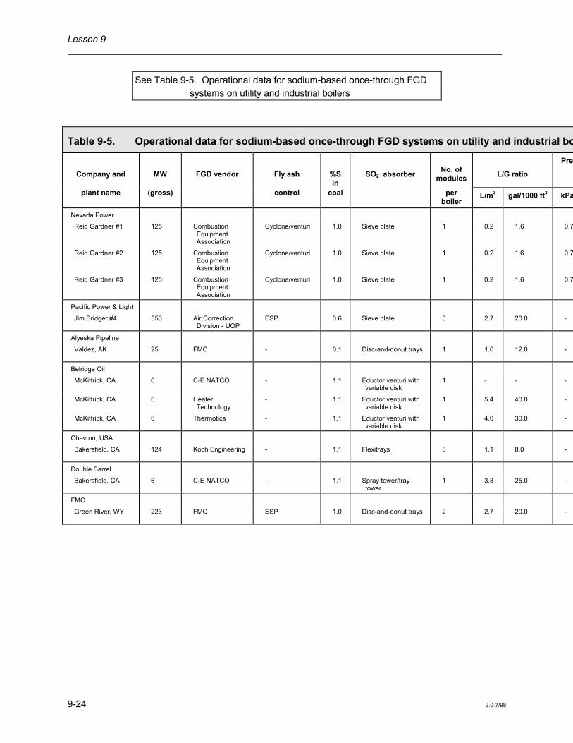
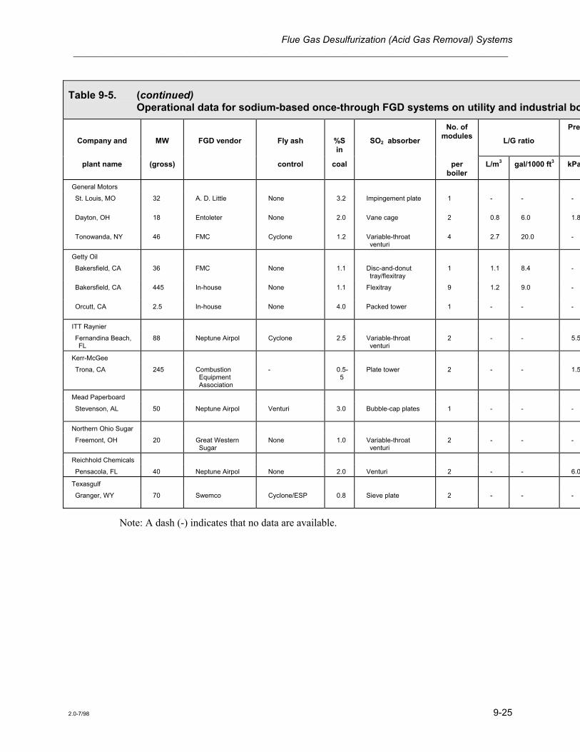
Operating Experience Presently a number of sodium-based throwaway FGD systems are in operation in the U.S., mainly on industrial boilers. Table 9-5 lists operating data for some of these systems. These systems are generally simpler to operate and maintain than lime or limestone systems. Therefore, reported operating problems have not been as severe or as frequent with the sodium-based system as with calcium-based systems. Control of pH, as with other FGD systems, is of prime concern to maximize absorption efficiency. Troubles with controlling pH can cause scale buildup and plugging of the sample lines. At high pH levels, the liquor absorbs CO2 and forms carbonate scale in systems where a high amount of calcium or magnesium is present (Makansi 1982). Other problems include ineffective entrainment separation, nozzle plugging, and failure of dampers, duct liners, and stack liners.
Lesson 9 ___________________________________________________________________________________
9-24 2.0-7/98
See Table 9-5. Operational data for sodium-based once-through FGD systems on utility and industrial boilers
Table 9-5. Operational data for sodium-based once-through FGD systems on utility and industrial bo
Company and
MW
FGD vendor
Fly ash
%S in
SO2 absorber
No. of
modules
L/G ratio
Pres
plant name (gross) control coal per boiler
L/m3 gal/1000 ft3 kPa
Nevada Power
Reid Gardner #1 125 Combustion Equipment Association
Cyclone/venturi 1.0 Sieve plate 1 0.2 1.6 0.7
Reid Gardner #2 125 Combustion Equipment Association
Cyclone/venturi 1.0 Sieve plate 1 0.2 1.6 0.7
Reid Gardner #3 125 Combustion Equipment Association
Cyclone/venturi 1.0 Sieve plate 1 0.2 1.6 0.7
Pacific Power & Light
Jim Bridger #4 550 Air Correction Division - UOP
ESP 0.6 Sieve plate 3 2.7 20.0 -
Alyeska Pipeline
Valdez, AK 25 FMC - 0.1 Disc-and-donut trays 1 1.6 12.0 -
Belridge Oil
McKittrick, CA 6 C-E NATCO - 1.1 Eductor venturi with variable disk
1 - - -
McKittrick, CA 6 Heater Technology
- 1.1 Eductor venturi with variable disk
1 5.4 40.0 -
McKittrick, CA 6 Thermotics - 1.1 Eductor venturi with variable disk
1 4.0 30.0 -
Chevron, USA
Bakersfield, CA 124 Koch Engineering - 1.1 Flexitrays 3 1.1 8.0 -
Double Barrel
Bakersfield, CA 6 C-E NATCO - 1.1 Spray tower/tray tower
1 3.3 25.0 -
FMC
Green River, WY 223 FMC ESP 1.0 Disc-and-donut trays 2 2.7 20.0 -
Flue Gas Desulfurization (Acid Gas Removal) Systems ___________________________________________________________________________________
2.0-7/98 9-25
Table 9-5. (continued) Operational data for sodium-based once-through FGD systems on utility and industrial bo
Company and
MW
FGD vendor
Fly ash
%S in
SO2 absorber
No. of modules
L/G ratio
Pres
plant name (gross) control coal per boiler
L/m3 gal/1000 ft3 kPa
General Motors
St. Louis, MO 32 A. D. Little None 3.2 Impingement plate 1 - - -
Dayton, OH 18 Entoleter None 2.0 Vane cage 2 0.8 6.0 1.8
Tonowanda, NY 46 FMC Cyclone 1.2 Variable-throat venturi
4 2.7 20.0 -
Getty Oil
Bakersfield, CA 36 FMC None 1.1 Disc-and-donut tray/flexitray
1 1.1 8.4 -
Bakersfield, CA 445 In-house None 1.1 Flexitray 9 1.2 9.0 -
Orcutt, CA 2.5 In-house None 4.0 Packed tower 1 - - -
ITT Raynier
Fernandina Beach, FL
88 Neptune Airpol Cyclone 2.5 Variable-throat venturi
2 - - 5.5
Kerr-McGee
Trona, CA 245 Combustion Equipment Association
- 0.5-5
Plate tower 2 - - 1.5
Mead Paperboard
Stevenson, AL 50 Neptune Airpol Venturi 3.0 Bubble-cap plates 1 - - -
Northern Ohio Sugar
Freemont, OH 20 Great Western Sugar
None 1.0 Variable-throat venturi
2 - - -
Reichhold Chemicals
Pensacola, FL 40 Neptune Airpol None 2.0 Venturi 2 - - 6.0
Texasgulf
Granger, WY 70 Swemco Cyclone/ESP 0.8 Sieve plate 2 - - -
Note: A dash (-) indicates that no data are available.

Lesson 9 ___________________________________________________________________________________
9-26 2.0-7/98
To test your knowledge of the preceding section, answer the questions in Part 5 of the Review Exercise.
Regenerable FGD Processes
Regenerable FGD processes remove SO2 from the flue gas and generate a saleable product. Regenerable products include elemental sulfur, sulfuric acid, or, in the case of lime or limestone scrubbing, gypsum (used for wallboard). Regenerable processes do not produce a sludge, thereby eliminating the sludge disposal problem. Most regenerable processes also achieve the following:
• Have the potential for consistently obtaining a high SO2 removal efficiency, usually exceeding 90%
• Utilize the scrubbing reagent more efficiently than nonregenerable processes
• Use scrubbing liquors that do not cause scaling and plugging problems in the scrubber
The major drawback of these processes is that systems using them are usually more complicated in design and are more expensive to install and operate.
Two regenerable processes presently operating in the U.S. are the Wellman-Lord and the magnesium oxide. The Wellman-Lord process has been widely used in both sulfuric acid and petroleum refining industries but has only been installed on a limited number of industrial and utility boilers. The magnesium oxide process has been tested at a number of utility boilers, but the Philadelphia Electric Company's Eddystone and Cromby Stations are the only utility boilers presently operating this process. Because of the limited use of regenerable processes in the utility industry, these processes are not covered in this course. Information on these processes can be obtained from numerous EPA and EPRI publications specific to the demonstration projects.
Emerging Technologies
As shown in Table 9-1 the overwhelming choice for SO2 control by utilities has been the use of lime or limestone wet scrubbers. The Clean Air Act Amendments of 1990 require reductions in acid rain precursors both SO2 and nitrogen oxides (NOx). Utilities have options as to specifically how they will comply; however, a number of new and/or retrofit FGD technologies will have to be installed. Because of the regulatory requirements and efforts to provide more efficient and cost-effective FGD systems, a number of new technologies are being investigated and developed by vendors, utilities and governmental agencies (EPA and DOE).
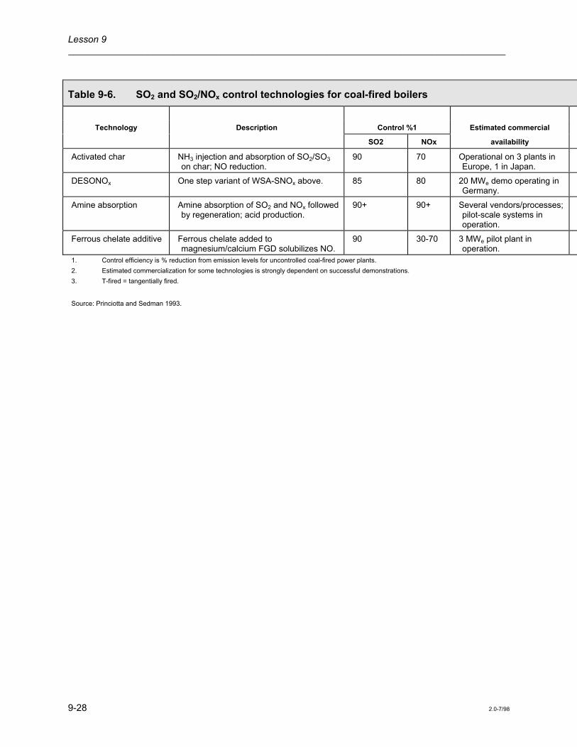
Table 9-6 provides summary information on certain new technologies that EPA has evaluated as likely candidates for retrofit to meet acid rain control requirements (Princiotta and Sedman 1993). Table 9-6 provides a description of specific SO2 and combined SO2/NOx control technologies as well as estimates of the level of control and commercial availability. Table 9-1 is not intended to be an all inclusive listing of every emerging FGD technology, as there are a number of others that may be viable options pending pilot demonstration.

Flue Gas Desulfurization (Acid Gas Removal) Systems ___________________________________________________________________________________
2.0-7/98 9-27
Table 9-6. SO2 and SO2/NOx control technologies for coal-fired boilers
Technology Description Control %1 Estimated commercial
SO2 NOx availability
Wet flue gas desulfurization (FGD)
Limestone or lime in water removes SO2 in a scrubber vessel. Additives may be used to enhance SO2 removal. A wet waste or gypsum is produced.
70-97 0 Current for new boilers and retrofit.
Dry FGD Lime in water removes SO2 in a spray dryer, which evaporates the water prior to the vessel exit. Produces a dry waste.
70-95 0 Current for low to moderate S coal for new boilers. High S coal retrofit, 5 yrs.
E-SOx/in-duct injection Lime and water are injected in a boiler duct and/or ESP (E-SOx) similar to a spray dryer.
50-70 0 Pilot scale only. Demonstrations required, 3-7 yrs.
Advanced silicate (ADVACATE)
Several variations. Most attractive: adding limestone to boiler, generating lime. Lime/fly ash collected in cyclone and reacted to generate highly reactive silicate sorbent. Moist sorbent added to downstream duct.
Up to 90 0 Pilot scale only. Demonstrations required, 3-7 yrs.
Limestone injection multistage burners (LIMB)
Low NOx burners and upper furnace sorbent injection. May use humidification to improve SO2 capture and ESP performance.
50-70 40-60 Wall-fired, current; T-fired3, 2 yrs
Natural gas reburning Boiler fired with 80-90% coal. Remaining fuel (natural gas) is injected higher in boiler to reduce NOx. Air added to complete burnout. Sorbent may be injected to capture SO2.
Without sorbent, 10-20; with sorbent 50-60
50-60 Demonstrations in progress
SNRB Ammonia (NH3) and lime/sodium injection upstream of catalyst-coated baghouse.
90 90 5 MWe pilot plant in operation.
NOxSO SO2/NOx absorption on alumina in fluid bed reactor.
90 90 5 MWe pilot plant in Clean Coal Technology (CCT) program.
WSA-SNOx Catalytic reduction of nitric oxide (NO) and oxidation of SO2 in two stages. Sulfuric acid recovery.
95 90 35 MWe pilot in CCT program; 1 unit in Denmark.
NONOx Ozone/NH3 promoted absorption of SO2/NOx in wet scrubber.
95 75-95 Commercial construction in Europe.
Lesson 9 ___________________________________________________________________________________
9-28 2.0-7/98
Table 9-6. SO2 and SO2/NOx control technologies for coal-fired boilers
Technology Description Control %1 Estimated commercial
SO2 NOx availability
Activated char NH3 injection and absorption of SO2/SO3 on char; NO reduction.
90 70 Operational on 3 plants in Europe, 1 in Japan.
DESONOx One step variant of WSA-SNOx above. 85 80 20 MWe demo operating in Germany.
Amine absorption Amine absorption of SO2 and NOx followed by regeneration; acid production.
90+ 90+ Several vendors/processes; pilot-scale systems in operation.
Ferrous chelate additive Ferrous chelate added to magnesium/calcium FGD solubilizes NO.
90 30-70 3 MWe pilot plant in operation.
1. Control efficiency is % reduction from emission levels for uncontrolled coal-fired power plants. 2. Estimated commercialization for some technologies is strongly dependent on successful demonstrations. 3. T-fired = tangentially fired.
Source: Princiotta and Sedman 1993.

Flue Gas Desulfurization (Acid Gas Removal) Systems ___________________________________________________________________________________
2.0-7/98 9-29
Summary
FGD systems have been installed and operated on many industrial and utility boilers and on some industrial processes for a number of years. These systems are capable of removing approximately 70 to 90% of the SO2 in the flue gas, depending on the operating conditions of the system. Some systems have achieved an SO2-removal efficiency of greater than 95%. The most popular FGD systems used on utility boilers are lime or limestone scrubbing. Approximately 75% of the FGD systems installed on utility boilers are either lime or limestone scrubbing. The use of dual-alkali systems on utility boilers is attractive because of their ability to remove SO2 very efficiently and to reduce scaling problems. The throwaway-sodium FGD systems have been used mostly on industrial boilers. These systems use a sodium scrubbing liquor that is very efficient in absorbing SO2 emissions, but they produce liquid wastes that can cause waste disposal problems. FGD systems used on utility boilers generate large quantities of liquid wastes. Therefore, throwaway-sodium systems have mainly been used on industrial boilers. Wellman-Lord FGD systems have been used to reduce SO2 emissions from utility and industrial boilers and from a number of industrial processes. These systems have the advantage of regenerating the scrubbing liquor and producing a saleable product instead of a sludge that can be a disposal problem. However, these systems are more expensive to install and operate than lime, limestone, or dual-alkali systems.
Over the past 25 years, a wealth of material has been written and documented concerning FGD control technology. The authors of this manual suggest that the readers utilize the many publications from EPA and the Electric Power Research Institute (EPRI) concerning this subject, particularly the proceedings from the FGD symposiums sponsored by the EPA.
To test your knowledge of the preceding section, answer the questions in Part 6 of the Review Exercise.

Lesson 9 ___________________________________________________________________________________
9-30 2.0-7/98

Flue Gas Desulfurization (Acid Gas Removal) Systems ___________________________________________________________________________________
2.0-7/98 9-31
Review Exercise Part 1
1. True or False? Only wet FGD systems have been used on utility boilers.
2. ____________________-based slurries absorb SO2 better than ____________________; however, the former are much more expensive.
a. Sodium, lime or limestone b. Lime or limestone, sodium c. Gypsum, lime or limestone d. Limestone, lime
3. Solutions of sodium compounds are referred to as clear liquor solutions because the compounds are:
a. Blue b. Soluble c. Insoluble d. Transparent
4. True or False? Almost all FGD systems use a single wet scrubber for both SO2 and fly ash removal.
5. Which problem/problems must be considered when trying to remove both SO2 and fly ash in the same scrubber?
a. Pressure drops are higher b. The scrubbing liquid, if recirculated, can contain a high level of fly ash c. SO2 absorption efficiency is normally lower d. All of the above
6. Spray towers on most FGD systems require higher ____________________ (for equivalent SO2 removal) than other absorber designs.
a. Pressure drops b. Gas velocities c. Liquid-to-gas ratios d. All of the above
7. When the gas velocity is lowered, entrainment becomes ____________________; however, the scrubber system will be ____________________ costly.
a. More, more b. More, less c. Less, more d. Less, less
Lesson 9 ___________________________________________________________________________________
9-32 2.0-7/98
8. List five properties of the coal (or fuel) that will affect FGD operation.
________________________________________
________________________________________
________________________________________
________________________________________
________________________________________
9. Because flue gas contains some SO2 as it exits the absorber, FGD systems generally use ____________________ to prevent corrosion.
a. Additional absorbers b. Reheaters c. Special construction materials for downstream fans and ductwork d. Both b and c
Part 2
10. List three nonregenerable FGD processes.
________________________________________
________________________________________
________________________________________
11. Dissolving lime in water is referred to as:
a. Clarifying b. Slaking c. Raking d. Thickening
12. What is CaSO3 in the following reaction?
Ca SO 2H OH++3= + -+ + +2 →CaSO H O3 2+ 2
a. Sludge b. Liquid c. Gas
13. Lime FGD systems use a(an) ____________________ to remove fly ash from the flue gas before it enters the absorber.
a. Venturi scrubber b. Electrostatic precipitator c. Mechanical collector with precipitator or scrubber d. Any of the above
Flue Gas Desulfurization (Acid Gas Removal) Systems ___________________________________________________________________________________
2.0-7/98 9-33
14. In early lime FGD systems, scale buildup and plugging of the ____________________ were particularly troublesome.
a. Spray nozzles b. Entrainment separator c. Scrubber internals d. All of the above
15. Operating a lime FGD system at a pH above 8.0 to 9.0:
a. Reduces scale buildup b. Increases the risk of scale buildup c. Is recommended d. Eliminates nozzle plugging
16. Most lime FGD systems on utility boilers operate at L/G ratios of:
a. 0.4 to 1.3 L/m3 (3 to 10 gal/1000 ft3) b. 3.0 to 8.0 L/m3 (25 to 60 gal/1000 ft3) c. 13 to 26 L/m3 (100 to 200 gal/1000 ft3) d. None of the above
17. ____________________ liquid-to-gas ratios reduce the potential for scale buildup.
a. High b. Low
18. Stack gas is reheated to:
a. Avoid condensation b. Enhance plume rise c. Give better pollutant dispersion d. All of the above
Part 3
19. Limestone FGD systems generally operate at ____________________ liquid-to-gas ratios than lime FGD systems because SO2 is ____________________ reactive with a limestone slurry.
a. Higher, more b. Higher, less c. Lower, more d. Lower, less
20. True or False? The chemistry for SO2 removal in a limestone slurry is very different from that for SO2 removal in a lime slurry.
21. The major difference in equipment for a limestone FGD system (compared to a lime FGD system) is in the:
a. Fly ash collection equipment b. Type of absorber c. Slurry feed preparation d. All of the above

Lesson 9 ___________________________________________________________________________________
9-34 2.0-7/98
22. True or False? Limestone is generally less expensive to purchase than lime.
23. In lime/limestone FGD systems, calcium sulfite formed as part of the sludge is difficult to remove from the slurry. One method used to eliminate this problem is to convert the calcium sulfite to calcium sulfate by the process called:
a. Forced oxidation b. Wellman-Lord c. Double-alkali d. Direct reduction
Part 4
24. Double-alkali processes generally use a ____________________ solution to absorb the SO2 from the flue gas and then react it with a ____________________ slurry to regenerate the absorbing solution.
a. Sodium, citrate b. Citrate, lime or limestone c. Sodium, lime or limestone d. Lime or limestone, sodium
25. In the double-alkali process, the sodium reagent is regenerated by reacting the sludge with lime. As part of this reaction, insoluble ____________________ are formed in the regeneration vessel.
a. Sodium salts b. Calcium salts c. Magnesium salts d. Citrate salts
26. Compared to lime and limestone scrubbing systems, double-alkali absorbers have a much lower:
a. Pressure drop b. Gas velocity c. Liquid-to-gas ratio d. All of the above
27. True or False? Using sodium-based scrubbing solutions (as compared to calcium-based) helps eliminate scale buildup.
Part 5
28. True or False? The two sodium compounds used most often in throwaway systems are sodium hydroxide (NaOH) and sodium carbonate (Na2CO3).
29. Sodium-based once-through FGD systems have been used on industrial boilers because:
a. Sodium is the most efficient of the commercial reagents b. They operate without scale buildup occurring c. They are often smaller and cheaper than other systems d. All of the above

Flue Gas Desulfurization (Acid Gas Removal) Systems ___________________________________________________________________________________
2.0-7/98 9-35
30. Large utilities have not used sodium-based once-through systems because of the expense of the sodium reagent and the:
a. Limited efficiency b. Low fly ash removal c. Presence of soluble salts in the wastes (wastes cannot be discharged into rivers or lakes) d. All of the above
31. True or False? In a sodium-based once-through FGD system, the flue gas may first pass through a baghouse or ESP.
32. True or False? Sodium-based once-through systems are generally simpler to operate and maintain than lime or limestone FGD systems.
33. At high pH values, the scrubbing liquid in the sodium systems absorbs ____________________ and can form carbonate scale.
a. SO2
b. CO2
c. O2
d. CaCO3
Part 6
34. Regenerable FGD processes generate a saleable product such as:
a. Sulfur b. Sulfuric acid c. Gypsum d. All of the above
35. List at least three advantages that the regenerable process has over the nonregenerable FGD process.
________________________________________
________________________________________
________________________________________

Lesson 9 ___________________________________________________________________________________
9-36 2.0-7/98

Flue Gas Desulfurization (Acid Gas Removal) Systems ___________________________________________________________________________________
2.0-7/98 9-37
Review Exercise Answers Part 1
1. False Dry FGD systems have been installed on some utility sized boilers (see Lesson 7).
2. a. Sodium, lime or limestone Sodium-based slurries absorb SO2 better than lime or limestone; however, the former are much more expensive.
3. b. Soluble Solutions of sodium compounds are referred to as clear liquor solutions because the compounds are soluble.
4. False Most FGD systems use two scrubbing stages: one for SO2 removal and another for fly ash removal.
5. d. All of the above Problems that must be considered when trying to remove both SO2 and fly ash in the same scrubber are:
• Pressure drops are higher
• The scrubbing liquid, if recirculated, can contain a high level of fly ash
• SO2 absorption efficiency is normally lower
6. c. Liquid-to-gas ratios Spray towers on most FGD systems require higher liquid-to-gas ratios (for equivalent SO2 removal) than other absorber designs. More liquid is used in spray towers because they have limited contact area available for absorption.
7. c. Less, more When the gas velocity is lowered, entrainment becomes less; however, the scrubber system will be more costly.
8. Five properties of coal (or fuel) that will affect FGD operation are:
• Heating value
• Sulfur content
• Chlorine content
• Ash content
• Moisture content
9. d. Both b and c Because flue gas contains some SO2 as it exits the absorber, FGD systems generally use reheaters and special construction materials for downstream fans and ductwork to prevent corrosion.

Lesson 9 ___________________________________________________________________________________
9-38 2.0-7/98
Part 2
10. Lime, Limestone, Double-alkali Three nonregenerable FGD processes are:
• Lime
• Limestone
• Double-alkali
11. b. Slaking Dissolving lime in water is referred to as slaking.
12. a. Sludge In the following reaction, CaSO3 is sludge.
Ca SO 2H OH++3= + -+ + +2 →CaSO H O3 2+ 2
13. d. Any of the above To remove fly ash from the flue gas before it enters the absorber, lime FGD systems can use any of the following:
• A venturi scrubber
• An electrostatic precipitator
• A mechanical collector with precipitator or scrubber
14. d. All of the above In early lime FGD systems, scale buildup and plugging of the spray nozzles, entrainment separator, and scrubber internals were particularly troublesome.
15. b. Increases the risk of scale buildup Operating a lime FGD system at a pH above 8.0 to 9.0 increases the risk of scale buildup.
16. b. 3.0 to 8.0 L/m3 (25 to 60 gal/1000 ft3) Most lime FGD systems on utility boilers operate at L/G ratios of 3.0 to 8.0 L/m3 (25 to 60 gal/1000 ft3).
17. a. High High liquid-to-gas ratios reduce the potential for scale buildup.
18. d. All of the above Stack gas is reheated to:
• Avoid condensation
• Enhance plume rise
• Give better pollutant dispersion

Flue Gas Desulfurization (Acid Gas Removal) Systems ___________________________________________________________________________________
2.0-7/98 9-39
Part 3
19. b. Higher, less Limestone FGD systems generally operate at higher liquid-to-gas ratios than lime FGD systems because SO2 is less reactive with a limestone slurry.
20. False The chemistry for SO2 removal in a limestone slurry is very similar to that for SO2 removal in a lime slurry.
21. c. Slurry feed preparation The major difference in equipment for a limestone FGD system (compared to a lime FGD system) is in the slurry feed preparation.
22. True Limestone is generally less expensive to purchase than lime.
23. a. Forced oxidation In lime/limestone FGD systems, calcium sulfite formed as part of the sludge is difficult to remove from the slurry. One method used to eliminate this problem is to convert the calcium sulfite to calcium sulfate by the process called forced oxidation.
Part 4
24. c. Sodium, lime or limestone Double-alkali processes generally use a sodium solution to absorb the SO2 from the flue gas and then react it with a lime or limestone slurry to regenerate the absorbing solution.
25. b. Calcium salts In the double-alkali process, the sodium reagent is regenerated by reacting the sludge with lime. As part of this reaction, insoluble calcium salts are formed in the regeneration vessel.
26. c. Liquid-to-gas ratio Compared to lime and limestone scrubbing systems, double-alkali absorbers have a much lower liquid-to-gas ratio. Double-alkali systems use sodium which is more effective at acid gas absorption than lime and limestone per mole of compound used. Therefore less sodium and less scrubbing liquid are required.
27. True Using sodium-based scrubbing solutions (as compared to calcium-based) helps eliminate scale buildup. Sodium compounds do not form slake as readily as calcium compounds do.
Part 5
28. True The two sodium compounds used most often in throwaway systems are sodium hydroxide (NaOH) and sodium carbonate (Na2CO3).

Lesson 9 ___________________________________________________________________________________
9-40 2.0-7/98
29. d. All of the above Sodium-based once-through FGD systems have been used on industrial boilers because:
• Sodium is the most efficient of the commercial reagents
• They operate without scale buildup occurring
• They are often smaller and cheaper than other systems
30. c. Presence of soluble salts in the wastes (wastes cannot be discharged into rivers or lakes)
Large utilities have not used sodium-based once-through systems because of the expense of the sodium reagent and the presence of soluble salts in the wastes which means wastes cannot be discharged into rivers or lakes.
31. True In a sodium-based once-through FGD system, the flue gas may first pass through a baghouse or ESP.
32. True Sodium-based once-through systems are generally simpler to operate and maintain than lime or limestone FGD systems.
33. b. CO2 At high pH values, the scrubbing liquid in the sodium systems absorbs CO2 and can form carbonate scale.
Part 6
34. d. All of the above Regenerable FGD processes generate a saleable product such as:
• Sulfur
• Sulfuric acid
• Gypsum
35. Avoidance of sludge disposal problems Consistently higher SO2 removal Better utilization of reagent Use of clear liquid solutions (reduces scaling)
Four advantages that the regenerable process has over the nonregenerable FGD process include:
• Avoidance of sludge disposal problems
• Consistently higher SO2 removal
• Better utilization of reagent
• Use of clear liquid solutions (reduces scaling)
Flue Gas Desulfurization (Acid Gas Removal) Systems ___________________________________________________________________________________
2.0-7/98 9-41
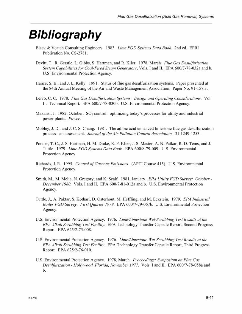
Bibliography Black & Veatch Consulting Engineers. 1983. Lime FGD Systems Data Book. 2nd ed. EPRI
Publication No. CS-2781.
Devitt, T., R. Gerstle, L. Gibbs, S. Hartman, and R. Klier. 1978, March. Flue Gas Desulfurization System Capabilities for Coal-Fired Steam Generators, Vols. I and II. EPA 600/7-78-032a and b. U.S. Environmental Protection Agency.
Hance, S. B., and J. L. Kelly. 1991. Status of flue gas desulfurization systems. Paper presented at the 84th Annual Meeting of the Air and Waste Management Association. Paper No. 91-157.3.
Leivo, C. C. 1978. Flue Gas Desulfurization Systems: Design and Operating Considerations. Vol. II. Technical Report. EPA 600/7-78-030b. U.S. Environmental Protection Agency.
Makansi, J. 1982, October. SO2 control: optimizing today’s processes for utility and industrial power plants. Power.
Mobley, J. D., and J. C. S. Chang. 1981. The adipic acid enhanced limestone flue gas desulfurization process - an assessment. Journal of the Air Pollution Control Association. 31:1249-1253.
Ponder, T. C., J. S. Hartman, H. M. Drake, R. P. Klier, J. S. Master, A. N. Patkar, R. D. Tems, and J. Tuttle. 1979. Lime FGD Systems Data Book. EPA 600/8-79-009. U.S. Environmental Protection Agency.
Richards, J. R. 1995. Control of Gaseous Emissions. (APTI Course 415). U.S. Environmental Protection Agency.
Smith, M., M. Melia, N. Gregory, and K. Scalf. 1981, January. EPA Utility FGD Survey: October - December 1980. Vols. I and II. EPA 600/7-81-012a and b. U.S. Environmental Protection Agency.
Tuttle, J., A. Paktar, S. Kothari, D. Osterhout, M. Heffling, and M. Eckstein. 1979. EPA Industrial Boiler FGD Survey: First Quarter 1979. EPA 600/7-79-067b. U.S. Environmental Protection Agency.
U.S. Environmental Protection Agency. 1976. Lime/Limestone Wet-Scrubbing Test Results at the EPA Alkali Scrubbing Test Facility. EPA Technology Transfer Capsule Report, Second Progress Report. EPA 625/2-75-008.
U.S. Environmental Protection Agency. 1976. Lime/Limestone Wet-Scrubbing Test Results at the EPA Alkali Scrubbing Test Facility. EPA Technology Transfer Capsule Report, Third Progress Report. EPA 625/2-76-010.
U.S. Environmental Protection Agency. 1978, March. Proceedings: Symposium on Flue Gas Desulfurization - Hollywood, Florida, November 1977. Vols. I and II. EPA 600/7-78-058a and b.

Lesson 9 ___________________________________________________________________________________
9-42 2.0-7/98
U.S. Environmental Protection Agency. 1979, May. Sulfur Emission: Control Technology and Waste Management. Decision Series. EPA 600/9-79-019.
U.S. Environmental Protection Agency. 1979, July. Proceedings: Symposium on Flue Gas Desulfurization - Las Vegas, Nevada, March 1979. Vols. I and II. EPA 600/7-79-167a and b.
U.S. Environmental Protection Agency. 1980, August. Controlling Sulfur Oxides. Research Summary. EPA 600/8-80-029.
U.S. Environmental Protection Agency. 1981, April. Control Techniques for Sulfur Oxide Emissions from Stationary Sources. EPA 450/3-81-004.
U.S. Environmental Protection Agency. 1981. Proceedings: Symposium on Flue Gas Desulfurization - Houston, Texas, October 1980. Vols. I and II. EPA 600/9-81-019a and b.
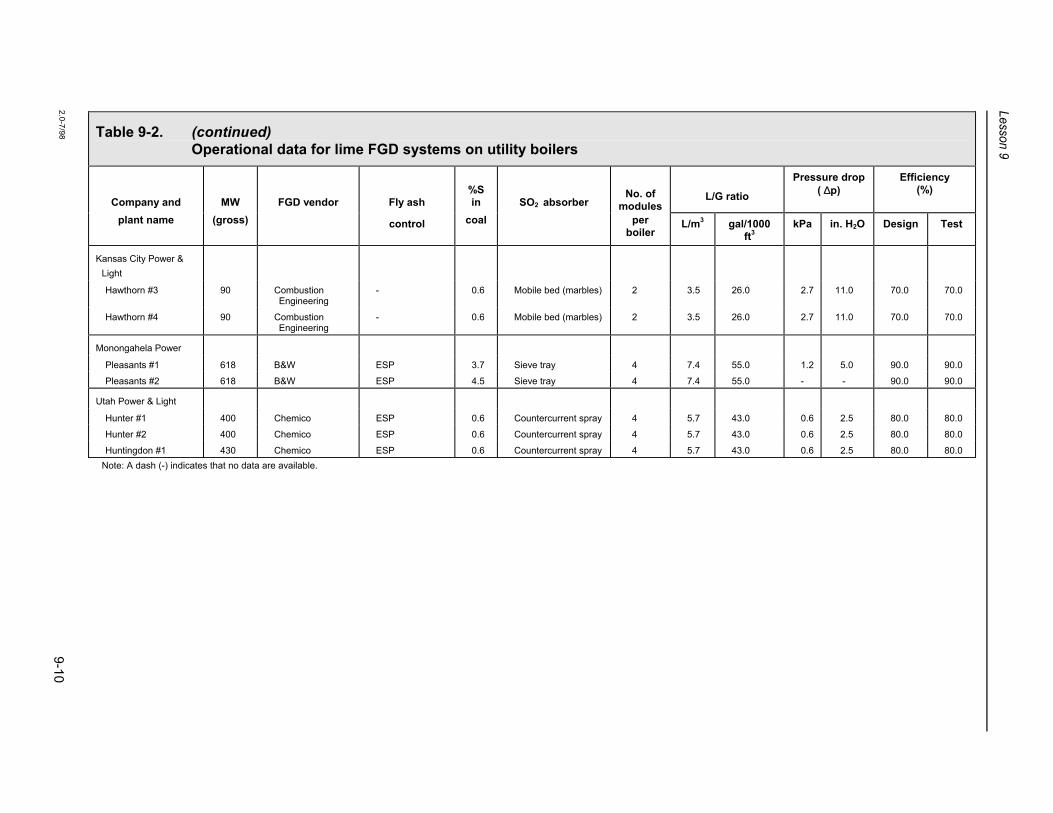
Table 9-2. (continued) Operational data for lime FGD systems on utility boilers
Company and
MW
FGD vendor
Fly ash
%S in
SO2 absorber
No. of
modules
L/G ratio
Pressure drop( ∆p)
Efficiency (%)
plant name (gross) control coal per boiler
L/m3 gal/1000 ft3
kPa in. H2O Design Test
Kansas City Power & Light
Hawthorn #3 90 Combustion Engineering
- 0.6 Mobile bed (marbles) 2 3.5 26.0 2.7 11.0 70.0 70.0
Hawthorn #4 90 Combustion Engineering
- 0.6 Mobile bed (marbles) 2 3.5 26.0 2.7 11.0 70.0 70.0
Monongahela Power
Pleasants #1 618 B&W ESP 3.7 Sieve tray 4 7.4 55.0 1.2 5.0 90.0 90.0
Pleasants #2 618 B&W ESP 4.5 Sieve tray 4 7.4 55.0 - - 90.0 90.0
Utah Power & Light
Hunter #1 400 Chemico ESP 0.6 Countercurrent spray 4 5.7 43.0 0.6 2.5 80.0 80.0
Hunter #2 400 Chemico ESP 0.6 Countercurrent spray 4 5.7 43.0 0.6 2.5 80.0 80.0
Huntingdon #1 430 Chemico ESP 0.6 Countercurrent spray 4 5.7 43.0 0.6 2.5 80.0 80.0 Note: A dash (-) indicates that no data are available.
2.0-7/98 9-10

Table 9-2. Operational data for lime FGD systems on utility boilers
Company and
MW
FGD vendor
Fly ash
%S in
SO2 absorber
No. of
modules
L/G ratio
Pressure drop( ∆p)
Efficiency (%)
plant name (gross) control coal per boiler
L/m3 gal/1000 ft3
kPa in. H2O Design Test
Pennsylvania Power
Bruce Mansfield #1 917 Chemico 1st-stage venturi 3.0 Fixed-throat venturi 6 6.0 45.0 2.0 8.0 92.1 95.0
Bruce Mansfield #2 917 Chemico 1st-stage venturi 3.0 Fixed-throat venturi 6 6.0 45.0 2.0 8.0 92.1 95.0
Bruce Mansfield #3 917 Pullman Kellogg ESP 3.0 Weir crosscurrent spray
6 - - 0.7 2.8 92.0 95.0
Columbus & Southern Ohio Electric
Conesville #5 411 Air Correction Division
ESP 4.7 Mobile bed 1 6.7 50.0 2.0 8.0 89.5 89.7
Conesville #6 411 Air Correction Division
ESP 4.7 Mobile bed 2 6.7 50.0 2.0 8.0 89.5 89.5
Duquesne Light
Elrama 510 Chemico ESP 2.2 Variable-throat venturi
5 5.3 40.0 4.0 16.0 83.0 86.0
Phillips 408 Chemico Cyclone/ESP 1.9 Variable-throat venturi
4 5.3 40.0 4.0 16.0 83.0 90.0
Kentucky Utilities
Green River 64 American Air Filter Cyclone/ variable-throat venturi
4.0 Mobile bed 1 4.5 34.0 1.0 4.0 80.0 80.0
Louisville Gas & Electric
Cane Run #4 188 American Air Filter ESP 3.7 Mobile bed 2 8.0 60.0 1.0 40.0 85.0 87.5
Cane Run #5 200 Combustion Engineering
ESP 3.7 Countercurrent spray 2 7.4 55.0 0.1 0.5 85.0 91.0
Mill Creek #1 358 Combustion Engineering
- 3.7 - - 12.7 95.0 - - 85.0 86.6
Mill Creek #3 442 American Air Filter ESP 3.7 Mobile bed 4 8.7 65.0 1.6 6.5 85.0 85.7
Paddy’s Run #6 72 Combustion Engineering
ESP 2.5 Mobile bed (marbles) 2 2.2 16.5 2.9 11.5 90.0 90.0
Continued on next page
2.0-7/98 9-9
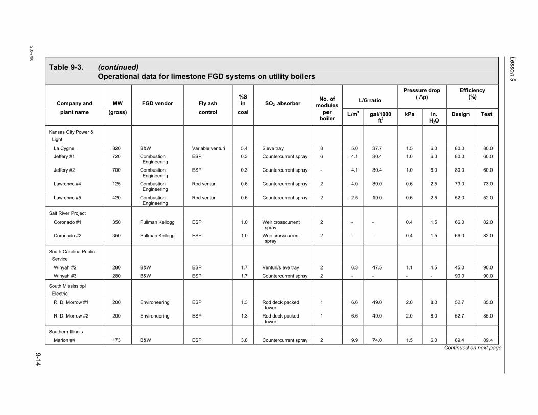
Table 9-3. (continued) Operational data for limestone FGD systems on utility boilers
Company and
MW
FGD vendor
Fly ash
%S in
SO2 absorber
No. of
modules
L/G ratio
Pressure drop( ∆p)
Efficiency (%)
plant name (gross) control coal per boiler
L/m3 gal/1000 ft3
kPa in. H2O
Design Test
Kansas City Power & Light
La Cygne 820 B&W Variable venturi 5.4 Sieve tray 8 5.0 37.7 1.5 6.0 80.0 80.0
Jeffery #1 720 Combustion Engineering
ESP 0.3 Countercurrent spray 6 4.1 30.4 1.0 6.0 80.0 60.0
Jeffery #2 700 Combustion Engineering
ESP 0.3 Countercurrent spray - 4.1 30.4 1.0 6.0 80.0 60.0
Lawrence #4 125 Combustion Engineering
Rod venturi 0.6 Countercurrent spray 2 4.0 30.0 0.6 2.5 73.0 73.0
Lawrence #5 420 Combustion Engineering
Rod venturi 0.6 Countercurrent spray 2 2.5 19.0 0.6 2.5 52.0 52.0
Salt River Project
Coronado #1 350 Pullman Kellogg ESP 1.0 Weir crosscurrent spray
2 - - 0.4 1.5 66.0 82.0
Coronado #2 350 Pullman Kellogg ESP 1.0 Weir crosscurrent spray
2 - - 0.4 1.5 66.0 82.0
South Carolina Public Service
Winyah #2 280 B&W ESP 1.7 Venturi/sieve tray 2 6.3 47.5 1.1 4.5 45.0 90.0
Winyah #3 280 B&W ESP 1.7 Countercurrent spray 2 - - - - 90.0 90.0
South Mississippi Electric
R. D. Morrow #1 200 Environeering ESP 1.3 Rod deck packed tower
1 6.6 49.0 2.0 8.0 52.7 85.0
R. D. Morrow #2 200 Environeering ESP 1.3 Rod deck packed tower
1 6.6 49.0 2.0 8.0 52.7 85.0
Southern Illinois
Marion #4 173 B&W ESP 3.8 Countercurrent spray 2 9.9 74.0 1.5 6.0 89.4 89.4 Continued on next page
2.0-7/98 9-14

Table 9-3. (continued) Operational data for limestone FGD systems on utility boilers
Company and
MW
FGD vendor
Fly ash
%S in
SO2 absorber
No. of
modules
L/G ratio
Pressure drop ( ∆p)
Efficiency (%)
plant name (gross) control coal per boiler
L/m3 gal/1000 ft3
kPa in. H2O Design Test
Springfield City
Southwest #1 194 Air Correction Division - UOP
ESP 3.5 Mobile bed (TCA) 2 5.5 41.0 1.5 6.0 80.0 87.0
Springfield Water, Light & Power
Dallman #3 205 Research-Cottrell Cyclone/ESP 3.3 Spray/packed tower 2 - - 0.2 0.7 95.0 95.0
TVA
Widows Creek #8 550 TVA ESP/venturi 3.7 Mobile packed bed
and grid packing
1
3
60.0 0.5 2.0 70.0 -
Texas Power & Light
Sandow #4 545 Combustion Engineering
ESP 1.6 Countercurrent spray 3 - - - - 75.0 -
Texas Utilities
Martin Lake #1 793 Research-Cottrell ESP 0.9 Spray/packed bed 6 - - 1.1 4.5 71.0 95.0
Martin Lake #2 793 Research-Cottrell ESP 0.9 Spray/packed bed 6 - - 1.1 4.5 71.0 95.0
Martin Lake #3 793 Research-Cottrell ESP 0.9 Spray/packed bed 6 - - 1.1 4.5 71.0 95.0
Monticello 800 Chemico ESP 1.5 Countercurrent spray 3 9.4 70.0 1.2 5.0 74.0 74.0
Note: A dash (-) indicates that no data are available.
9-15 2.0-7/98

Table 9-3. Operational data for limestone FGD systems on utility boilers
Company and
MW
FGD vendor
Fly ash
%S in
SO2 absorber
No. of
modules
L/G ratio
Pressure drop( ∆p)
Efficiency (%)
plant name (gross) control coal per boiler
L/m3 gal/1000 ft3
kPa in. H2O Design Test
Alabama Electric
Tombigbee #2 255 Peabody ESP 1.2 Countercurrent spray 2 9.4 70.0 1.0 4.0 59.5 85.0
Tombigbee #3 255 Peabody ESP 1.2 Countercurrent spray 2 9.4 70.0 1.0 4.0 59.5 85.0
Arizona Electric Power
Apache #2 195 Research-Cottrell ESP 0.5 Spray/packed bed 2 2.8 20.6 1.5 6.0 42.5 97.0
Apache #3 195 Research-Cottrell ESP 0.5 Spray/packed bed 2 2.8 20.6 1.5 6.0 42.5 97.0
Cholla #1 119 Research-Cottrell Cyclone/venturi 0.5 Spray/packed bed 1 6.5 48.9 0.1 0.5 58.5 92.0
Cholla #2 264 Research-Cottrell Cyclone/venturi 0.5 Spray/packed bed 4 6.5 48.9 0.1 0.5 75.0 85.0
Basin Electric Power
Laramie River #1 570 Research-Cottrell ESP 0.8 Spray/packed bed 5 8.0 60.0 - - 90.0 90.0
Laramie River #2 570 Research-Cottrell ESP 0.8 Spray/packed bed 5 8.0 60.0 - - 90.0 90.0
Central Illinois Light
Duck Creek #1 416 Environeering ESP 3.7 Rod deck packed tower
4 6.7 50.0 2.0 8.0 85.0 85.0
Colorado Ute Electrical
Craig #1 447 Peabody ESP 0.4 Countercurrent spray 4 6.7 50.0 1.6 6.5 85.0 85.0
Craig #2 455 Peabody ESP 0.4 Countercurrent spray 4 6.7 50.0 1.6 6.5 85.0 85.0
Commonwealth Edison
Powerton 450 Air Correction Division - UOP
ESP 3.5 Mobile bed (TCA) 3 8.0 60.0 3.0 12.0 74.0 75.5
Indianapolis Power & Light
Petersburg #3 532 Air Correction Division - UOP
ESP 3.2 Mobile bed (TCA) 4 6.7 50.0 1.7 7.0 85.0 85.0
Continued on next page
2.0-7/98 9-13

Table 9-4. Operational data for double-alkali FGD systems on utility and industrial boilers
Company and plant name
MW
FGD vendor
Fly ash control
%S in
SO2 absorber
No. of
modules per
L/G ratio
Pressure drop ( ∆p)
Efficiency (%)
(gross) coal boiler L/m3 gal/1000 ft3
kPa in. H2O Design Test
Central Illinois Public Service
Newton #1 617 Buell ESP 2.5 Mobile bed 4 1.3 10.0 1.5 6.0 90.0 90.0
Louisville Gas & Electric
Cane Run #6 299 Combustion Equipment Association
ESP 4.8 Sieve plates 2 1.3 10.0 2.5 9.9 95.0 94.2
Southern Indiana Gas & Electric
A. B. Brown #1 265 FMC ESP 3.6 Variable-throat venturi
2 1.3 10.0 2.5 10.0 85.0 85.0
Caterpillar Tractor
East Peoria, IL 105 FMC Cyclone 3.2 Venturi 4 2.2 16.0 - - - 90.0
Joliet, IL 34 Zurn Cyclone 3.2 Dustraxtor 2 - - - - - 90.0
Morton, IL 19 Zurn Cyclone 3.2 Dustraxtor 2 - - - - - 90.0
Mossville, IL 70 FMC Cyclone - Venturi 4 1.2 8.6 - - - 90.0+
Firestone Tire
Pottstown, PA 4 FMC Cyclone 3.0 Venturi 1 1.3 10.0 - - - 90.5
General Motors
Parma, OH 64 GM Environmental Cyclone - Bubble-cap plates 4 2.6 20.0 0.9 8.0 - 90.0 Note: A dash (-) indicates that no data are available.
9-20 2.0-7/98

Table 9-5. Operational data for sodium-based once-through FGD systems on utility and industrial boilers
Company and
MW
FGD vendor
Fly ash
%S in
SO2 absorber
No. of
modules
L/G ratio
Pressure drop( ∆p)
Efficiency (%)
plant name (gross) control coal per boiler
L/m3 gal/1000 ft3 kPa in. H2O Design Test
Nevada Power
Reid Gardner #1 125 Combustion Equipment Association
Cyclone/venturi 1.0 Sieve plate 1 0.2 1.6 0.7 3.0 90.0 -
Reid Gardner #2 125 Combustion Equipment Association
Cyclone/venturi 1.0 Sieve plate 1 0.2 1.6 0.7 3.0 90.0 91.2
Reid Gardner #3 125 Combustion Equipment Association
Cyclone/venturi 1.0 Sieve plate 1 0.2 1.6 0.7 3.0 85.0 91.2
Pacific Power & Light
Jim Bridger #4 550 Air Correction Division - UOP
ESP 0.6 Sieve plate 3 2.7 20.0 - - 91.0 91.0
Alyeska Pipeline
Valdez, AK 25 FMC - 0.1 Disc-and-donut trays 1 1.6 12.0 - - - 96.0
Belridge Oil
McKittrick, CA 6 C-E NATCO - 1.1 Eductor venturi with variable disk
1 - - - - - 90.0
McKittrick, CA 6 Heater Technology
- 1.1 Eductor venturi with variable disk
1 5.4 40.0 - - - 90.0
McKittrick, CA 6 Thermotics - 1.1 Eductor venturi with variable disk
1 4.0 30.0 - - - 90.0
Chevron, USA
Bakersfield, CA 124 Koch Engineering - 1.1 Flexitrays 3 1.1 8.0 - - - 90.0
Double Barrel
Bakersfield, CA 6 C-E NATCO - 1.1 Spray tower/tray tower
1 3.3 25.0 - - - 95.0
FMC
Green River, WY 223 FMC ESP 1.0 Disc-and-donut trays 2 2.7 20.0 - - - 95.0
Continued on next page 9-24 2.0-7/98

Table 9-6. (continued) SO2 and SO2/NOx control technologies for coal-fired boilers
Technology Description Control %1 Estimated commercial Comments
SO2 NOx availability
Activated char NH3 injection and absorption of SO2/SO3 on char; NO reduction.
90 70 Operational on 3 plants in Europe, 1 in Japan.
DESONOx One step variant of WSA-SNOx above. 85 80 20 MWe demo operating in Germany.
Amine absorption Amine absorption of SO2 and NOx followed by regeneration; acid production.
90+ 90+ Several vendors/processes; pilot-scale systems in operation.
Ferrous chelate additive Ferrous chelate added to magnesium/calcium FGD solubilizes NO.
90 30-70 3 MWe pilot plant in operation.
1. Control efficiency is % reduction from emission levels for uncontrolled coal-fired power plants. 2. Estimated commercialization for some technologies is strongly dependent on successful demonstrations. 3. T-fired = tangentially fired.
Source: Princiotta and Sedman 1993.
9-28 2.0-7/98

Table 9-5. (continued) Operational data for sodium-based once-through FGD systems on utility and industrial boilers
Company and
MW
FGD vendor
Fly ash
%S in
SO2 absorber
No. of
modules
L/G ratio
Pressure drop( ∆p)
Efficiency (%)
plant name (gross) control coal per boiler
L/m3 gal/1000 ft3 kPa in. H2O Design Test
General Motors
St. Louis, MO 32 A. D. Little None 3.2 Impingement plate 1 - - - - - 90.0
Dayton, OH 18 Entoleter None 2.0 Vane cage 2 0.8 6.0 1.8 7.0 - 86.0
Tonowanda, NY 46 FMC Cyclone 1.2 Variable-throat venturi
4 2.7 20.0 - - - 95.0
Getty Oil
Bakersfield, CA 36 FMC None 1.1 Disc-and-donut tray/flexitray
1 1.1 8.4 - - - 90.0
Bakersfield, CA 445 In-house None 1.1 Flexitray 9 1.2 9.0 - - - 96.0
Orcutt, CA 2.5 In-house None 4.0 Packed tower 1 - - - - - 94.0
ITT Raynier
Fernandina Beach, FL
88 Neptune Airpol Cyclone 2.5 Variable-throat venturi
2 - - 5.5 22.0 - 85.0
Kerr-McGee
Trona, CA 245 Combustion Equipment Association
- 0.5-5 Plate tower 2 - - 1.5 6.0 98.0
Mead Paperboard
Stevenson, AL 50 Neptune Airpol Venturi 3.0 Bubble-cap plates 1 - - - - - 95.0
Northern Ohio Sugar
Freemont, OH 20 Great Western Sugar
None 1.0 Variable-throat venturi
2 - - - - - -
Reichhold Chemicals
Pensacola, FL 40 Neptune Airpol None 2.0 Venturi 2 - - 6.0 24.0 - -
2.0-7/98 9-25
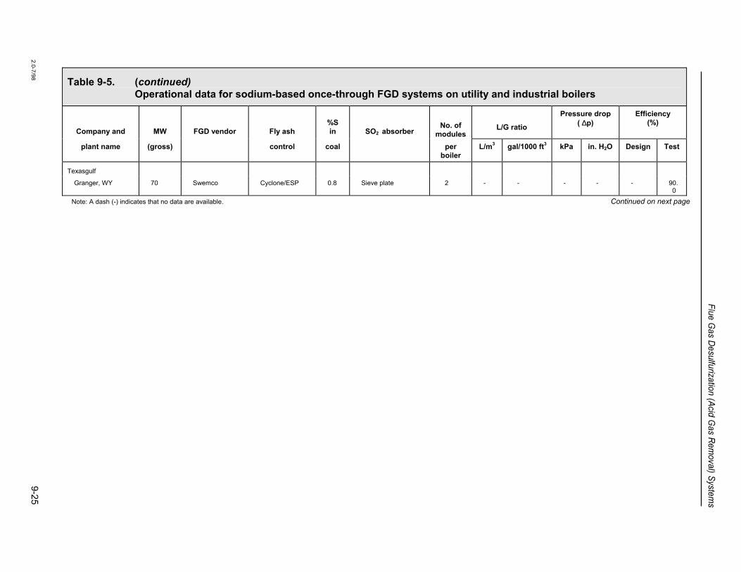
Table 9-5. (continued) Operational data for sodium-based once-through FGD systems on utility and industrial boilers
Company and
MW
FGD vendor
Fly ash
%S in
SO2 absorber
No. of
modules
L/G ratio
Pressure drop( ∆p)
Efficiency (%)
plant name (gross) control coal per boiler
L/m3 gal/1000 ft3 kPa in. H2O Design Test
Texasgulf
Granger, WY 70 Swemco Cyclone/ESP 0.8 Sieve plate 2 - - - - - 90.0
Note: A dash (-) indicates that no data are available. Continued on next page
2.0-7/98 9-25
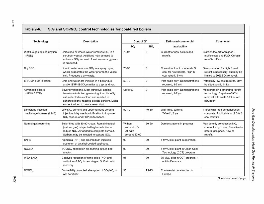
Table 9-6. SO2 and SO2/NOx control technologies for coal-fired boilers
Technology Description Control %1 Estimated commercial Comments
SO2 NOx availability
Wet flue gas desulfurization (FGD)
Limestone or lime in water removes SO2 in a scrubber vessel. Additives may be used to enhance SO2 removal. A wet waste or gypsum is produced.
70-97 0 Current for new boilers and retrofit.
State-of-the-art for higher S (sulfur) coal and FGD. Certain retrofits difficult.
Dry FGD Lime in water removes SO2 in a spray dryer, which evaporates the water prior to the vessel exit. Produces a dry waste.
70-95 0 Current for low to moderate S coal for new boilers. High S coal retrofit, 5 yrs.
Demonstration for high S coal retrofit is necessary, but may be limited to 90% SO2 removal.
E-SOx/in-duct injection Lime and water are injected in a boiler duct and/or ESP (E-SOx) similar to a spray dryer.
50-70 0 Pilot scale only. Demonstrations required, 3-7 yrs.
Potentially low cost retrofits. May be site-specific limits.
Advanced silicate (ADVACATE)
Several variations. Most attractive: adding limestone to boiler, generating lime. Lime/fly ash collected in cyclone and reacted to generate highly reactive silicate sorbent. Moist sorbent added to downstream duct.
Up to 90 0 Pilot scale only. Demonstrations required, 3-7 yrs.
Most promising emerging retrofit technology. Capable of 90% removal with costs 50% of wet scrubber.
Limestone injection multistage burners (LIMB)
Low NOx burners and upper furnace sorbent injection. May use humidification to improve SO2 capture and ESP performance.
50-70 40-60 Wall-fired, current; T-fired3, 2 yrs
T-fired wall-fired demonstration complete. Applicable to ≤ 3% S coal retrofits.
Natural gas reburning Boiler fired with 80-90% coal. Remaining fuel (natural gas) is injected higher in boiler to reduce NOx. Air added to complete burnout. Sorbent may be injected to capture SO2.
Without sorbent, 10-20; with sorbent 50-60
50-60 Demonstrations in progress May be only combustion NOx control for cyclones. Sensitive to natural gas price. New or retrofit.
SNRB Ammonia (NH3) and lime/sodium injection upstream of catalyst-coated baghouse.
90 90 5 MWe pilot plant in operation.
NOxSO SO2/NOx absorption on alumina in fluid bed reactor.
90 90 5 MWe pilot plant in Clean Coal Technology (CCT) program.
WSA-SNOx Catalytic reduction of nitric oxide (NO) and oxidation of SO2 in two stages. Sulfuric acid recovery.
95 90 35 MWe pilot in CCT program; 1 unit in Denmark.
NONOx Ozone/NH3 promoted absorption of SO2/NOx in wet scrubber.
95 75-95 Commercial construction in Europe.
Continued on next page
2.0-7/98 9-27