flowserve mechanical seal plan
TRANSCRIPT
Mechanical Seal Piping Plans
Experience In Motion
Single Seals plans 01, 02, 11, 13, 14, 21, 23, 31, 32, 41
Dual Seals plans 52, 53A, 53B, 53C, 54
Quench Seals plans 62, 65
Gas Seals plans 72, 74, 75, 76
Flow Solutions
Flowserve’s Flow Solutions Division recognizes one of the most effective ways toachieve long, uninterrupted mechanical seal life is to create a healthyenvironment around the seal faces. Piping plans help keep mechanical sealsrunning cool and clean, promote safe handling of dangerous fluids, and extendthe operational availability of rotating equipment. This reference book provides aconcise summary of the most essential piping plans used successfully in today’sprocess plants.
Each plan shows all the standard and optional auxiliary components referencedin ISO 21049 / API Standard 682 and recommended by Flowserve. Consult yourlocal Flowserve Flow Solutions Sales Engineer to identify the right solution thatsatisfies your application requirements.
Mechanical Seal Piping Plans
© 2005 Flowserve Corporation
outlet
inlet
pressure source,normally open
pressure indicator
pressure switch
level switch (high)
level switch (low)
cooling in
cooling coils
drain,normally closed
level indicator
cooling out
reservoir
liquid fill,normally closed
flowserve.com
What• Pressurized barrier fluid circulation through reservoir.• Fluid is circulated by a pumping ring in the dual seal assembly.
Why• Isolate process fluid.• Zero process emissions.
Where• Used with dual pressurized seals (Arrangement 3 or “double”).• High vapor pressure fluids, light hydrocarbons.• Hazardous/toxic fluids.• Heat transfer fluids.• Dirty/abrasive or polymerizing fluids.• Mixers/agitators and vacuum service.
Presventative Maintenance - Reference Appendix A• Piping loop must self-vent to reservoir locate at highest elevation.• Reservoir must be pressurized at all times - typically gas charge up to 200 psi (14bar).• Barrier fluid must be compatible with process.• Reservoir level gage indicates both inboard and outboard seal leakage.
Pla
n 5
3A
Pla
n 5
3A
sealend view
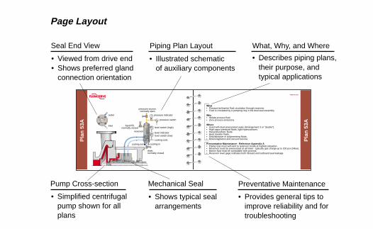
Seal End View Piping Plan Layout What, Why, and Where
Pump Cross-section Mechanical Seal Preventative Maintenance
• Viewed from drive end• Shows preferred gland
connection orientation
• Illustrated schematicof auxiliary components
• Describes piping plans,their purpose, andtypical applications
• Simplified centrifugalpump shown for allplans
• Shows typical sealarrangements
• Provides general tips toimprove reliability and fortroubleshooting
Page Layout
Pla
n 0
1
sealend view
internal porting
flowserve.com
Pla
n 0
1
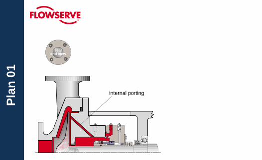
WhatInternal seal chamber flush from pump discharge.Operates similar to Plan 11.
WhySeal chamber heat removal.Seal chamber venting on horizontal pumps.Reduce risk of freezing/polymerizing fluid in exposed Plan 11 piping.
WhereCustom seal chamber, most likely an ANSI/ASME pump.Clean, moderate temperature fluids.Used with single seals, rarely with dual seals.
Preventative MaintenanceFlush typically can not be directed over seal faces and seal heat removal is limited.Calculate flush flow rate based on head loss through internal porting.
Pla
n 0
2
sealend view
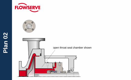
open throat seal chamber shown
flowserve.com
Pla
n 0
2
WhatDead-ended seal chamber with no flush.
WhyNo fluid recirculation needed.
WhereLarge bore/open throat seal chambers in moderate temperature services.Cooling jacket seal chambers in high temperature services.Clean fluids.Top-entry mixers/agitators with dry seals.
Preventative MaintenanceProcess must have adequate boiling point margin to avoid vaporization.Cooling fluid in seal chamber jacket may be needed at all times in hot services.Horizontal equipment must be self-venting.Often used in combination with steam quench, Plan 62.
Pla
n 1
1
sealend view
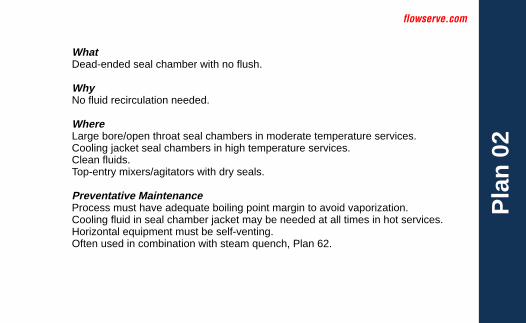
inlet
orifice
flowserve.com
Pla
n 1
1
WhatSeal flush from pump discharge through orifice.Default single seal flush plan.
WhySeal chamber heat removal.Seal chamber venting on horizontal pumps.Increase seal chamber pressure and fluid vapor margin.
WhereGeneral applications with clean fluids.Clean, non-polymerizing fluids.
Preventative MaintenanceUse an orifice with a minimum 0.125" (3 mm) diameter.Calculate flow rates to size orifice for adequate seal chamber flow.Increase boiling point margin with proper orifice and throat bushing sizing.Flush should be directed over seal faces with piping at 12 O’clock position.Typical failure mode is a clogged orifice - check temperatures at pipe ends.

Pla
n 1
3
sealend view
outlet
orifice
flowserve.com
Pla
n 1
3
WhatRecirculation from seal chamber to pump suction through orifice.Standard flush plan on vertical pumps.
WhyContinuous seal chamber venting on vertical pumps.Seal chamber heat removal.
WhereVertical pumps.Seal chamber pressure is greater than suction pressure.Moderate temperature fluids with moderate solids.Non-polymerizing fluids.
Preventative MaintenanceVent piping loop prior to starting vertical pumps.Use an orifice with a minimum 0.125" (3 mm) diameter.Calculate flow rates to size orifice for adequate seal chamber flow.Reduce seal chamber pressure with proper orifice and throat bushing sizing.Typical failure mode is a clogged orifice - check temperatures at pipe ends.
Pla
n 1
4
sealend view
orifices
outlet
inlet
flowserve.com
Pla
n 1
4
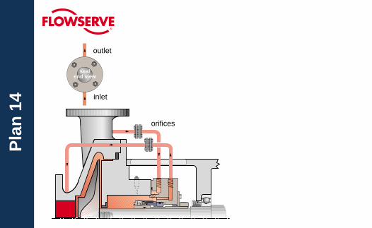
WhatSeal flush from pump discharge and recirculation to pump suction with orifices.Combination of Plan 11 and Plan 13.
WhyContinuous seal chamber venting on vertical pumps.Seal chamber heat removal.Increase seal chamber pressure and fluid vapor margin.
WhereVertical pumps.Clean, non-polymerizing fluids at moderate temperatures.
Preventative MaintenanceUse an orifice with a minimum 0.125" (3 mm) diameter.Calculate flow rates to size orifice for adequate seal chamber flow.Increase boiling point margin with proper orifice and throat bushing sizing.Flush should be directed over seal faces.Vent piping loop prior to starting vertical pumps.Typical failure mode is a clogged orifice - check temperatures at pipe ends.
Pla
n 2
1
sealend view
drain,normallyclosed
inlet
vents,normally closed
cooling in
cooler
cooling out
orifice
cooling coils
temperatureindicator
flowserve.com
Pla
n 2
1
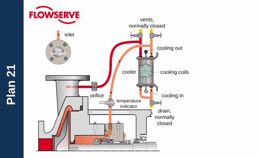
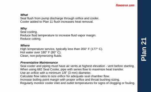
WhatSeal flush from pump discharge through orifice and cooler.Cooler added to Plan 11 flush increases heat removal.
WhySeal cooling.Reduce fluid temperature to increase fluid vapor margin.Reduce coking.
WhereHigh temperature service, typically less than 350° F (177° C).Hot water over 180° F (80° C).Clean, non-polymerizing fluids.
Preventative MaintenanceSeal cooler and piping must have air vents at highest elevation - vent before starting.When using 682 Seal Cooler, pipe with series flow to maximize heat transfer.Use an orifice with a minimum 1/8" (3 mm) diameter.Calculate flow rates to size orifice for adequate seal chamber flow.Increase boiling point margin with proper orifice and throat bushing sizing.Regularly monitor cooler inlet and outlet temperatures for signs of clogging or fouling.
Pla
n 2
3
sealend view
outlet
inlet
drain,normallyclosed
vent,normally closed
cooling in
cooler
cooling out
cooling coils
temperatureindicator
flowserve.com
Pla
n 2
3
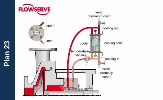
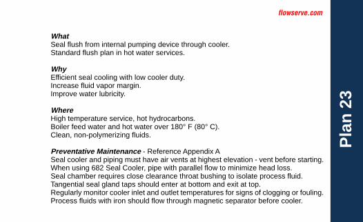
WhatSeal flush from internal pumping device through cooler.Standard flush plan in hot water services.
WhyEfficient seal cooling with low cooler duty.Increase fluid vapor margin.Improve water lubricity.
WhereHigh temperature service, hot hydrocarbons.Boiler feed water and hot water over 180° F (80° C).Clean, non-polymerizing fluids.
Preventative Maintenance - Reference Appendix ASeal cooler and piping must have air vents at highest elevation - vent before starting.When using 682 Seal Cooler, pipe with parallel flow to minimize head loss.Seal chamber requires close clearance throat bushing to isolate process fluid.Tangential seal gland taps should enter at bottom and exit at top.Regularly monitor cooler inlet and outlet temperatures for signs of clogging or fouling.Process fluids with iron should flow through magnetic separator before cooler.
Pla
n 3
1
sealend view
inlet
cyclone separator
flowserve.com
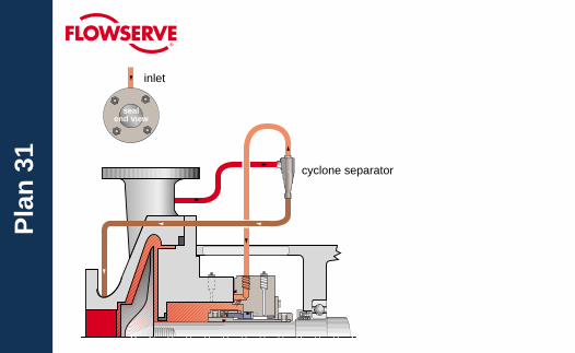
Pla
n 3
1
WhatSeal flush from pump discharge through cyclone separator.Centrifuged solids are returned to pump suction.
WhySeal chamber heat removal.Solids removal from flush and seal chamber.
WhereDirty or contaminated fluids, water with sand or pipe slag.Non-polymerizing fluids.
Preventative MaintenanceCyclone separator works best on solids with a specific gravity twice the process fluid.Seal chamber pressure must be nearly equal to suction pressure for proper flows.Piping should not include an orifice and is not expected to vent the seal chamber.Typical failure mode is clogged separator or pipes - check temperatures at pipe ends.
Pla
n 3
2
sealend view
inlet
flowindicator(optional)
flow controlvalve
pressureindicator
checkvalve
from cleansource,normally
openstrainer
temperatureindicator(optional)
flowserve.com
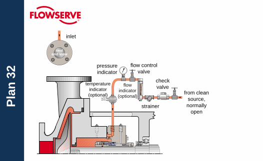
Pla
n 3
2
WhatSeal flush from an external clean source.
WhySeal chamber heat removal.Process and solids removal from seal chamber.Increase seal chamber pressure and fluid vapor margin.
WhereDirty or contaminated fluids, paper pulp.High temperature service.Polymerizing and/or oxidizing fluids.
Preventative MaintenanceUse throat bushing sized to hold pressure or maintain flow velocity.To restrict dirty process fluid, regulate injection flow rate.To increase fluid vapor margin, regulate injection pressure.Injection fluid must be compatible with process fluid.Regularly monitor control system for closed valves or signs of plugging.
Pla
n 4
1
sealend view
inlet
drain,normallyclosed
vents,normally closed
cooling in
cooler
cooling out
cooling coils
cycloneseparator
temperatureindicator
flowserve.com
Pla
n 4
1
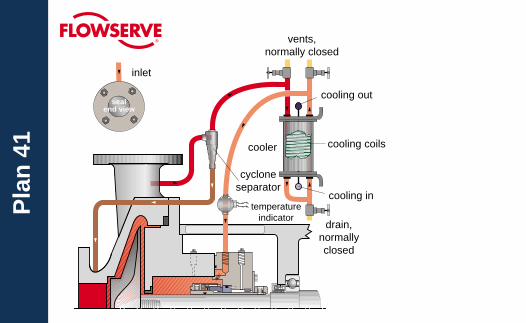
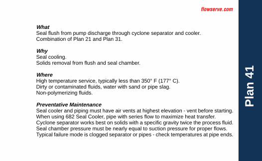
WhatSeal flush from pump discharge through cyclone separator and cooler.Combination of Plan 21 and Plan 31.
WhySeal cooling.Solids removal from flush and seal chamber.
WhereHigh temperature service, typically less than 350° F (177° C).Dirty or contaminated fluids, water with sand or pipe slag.Non-polymerizing fluids.
Preventative MaintenanceSeal cooler and piping must have air vents at highest elevation - vent before starting.When using 682 Seal Cooler, pipe with series flow to maximize heat transfer.Cyclone separator works best on solids with a specific gravity twice the process fluid.Seal chamber pressure must be nearly equal to suction pressure for proper flows.Typical failure mode is clogged separator or pipes - check temperatures at pipe ends.
sealend view
Pla
n 5
2
outlet
inlet
drain,normallyclosed
vent,normally open
cooling in
pressure indicator
cooling outcooling coils
reservoir
pressure switch(high)
level indicatorlevel switch (high)
level switch (low)
liquid fill,normally closed
orifice
flowserve.com
Pla
n 5
2
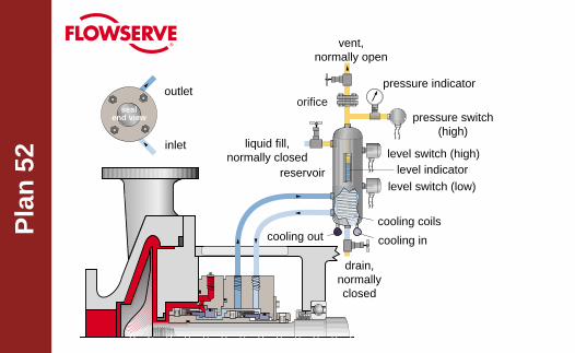
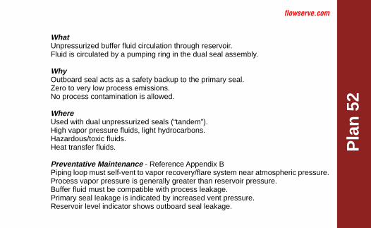
WhatUnpressurized buffer fluid circulation through reservoir.Fluid is circulated by a pumping ring in the dual seal assembly.
WhyOutboard seal acts as a safety backup to the primary seal.Zero to very low process emissions.No process contamination is allowed.
WhereUsed with dual unpressurized seals (“tandem”).High vapor pressure fluids, light hydrocarbons.Hazardous/toxic fluids.Heat transfer fluids.
Preventative Maintenance - Reference Appendix BPiping loop must self-vent to vapor recovery/flare system near atmospheric pressure.Process vapor pressure is generally greater than reservoir pressure.Buffer fluid must be compatible with process leakage.Primary seal leakage is indicated by increased vent pressure.Reservoir level indicator shows outboard seal leakage.
Pla
n 5
3A
sealend view
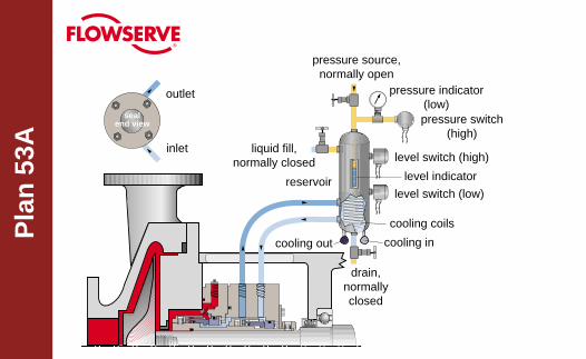
outlet
inlet
pressure source,normally open
pressure indicator(low)pressure switch
(high)
level switch (high)
level switch (low)
cooling coils
cooling in
drain,normallyclosed
cooling out
reservoir
liquid fill,normally closed
level indicator
flowserve.com
Pla
n 5
3A
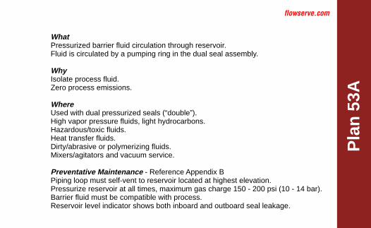
WhatPressurized barrier fluid circulation through reservoir.Fluid is circulated by a pumping ring in the dual seal assembly.
WhyIsolate process fluid.Zero process emissions.
WhereUsed with dual pressurized seals (“double”).High vapor pressure fluids, light hydrocarbons.Hazardous/toxic fluids.Heat transfer fluids.Dirty/abrasive or polymerizing fluids.Mixers/agitators and vacuum service.
Preventative Maintenance - Reference Appendix BPiping loop must self-vent to reservoir located at highest elevation.Pressurize reservoir at all times, maximum gas charge 150 - 200 psi (10 - 14 bar).Barrier fluid must be compatible with process.Reservoir level indicator shows both inboard and outboard seal leakage.
Pla
n 5
3B
sealend view
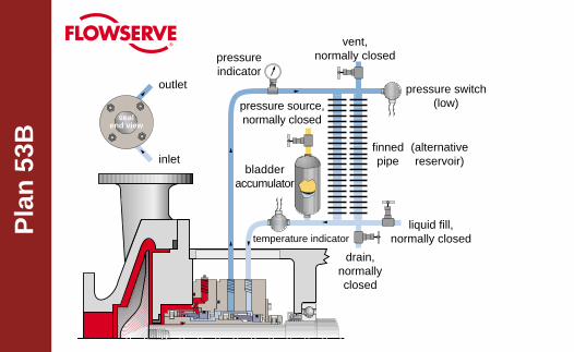
outlet
inlet
pressure source,normally closed
pressureindicator
pressure switch(low)
drain,normallyclosed
liquid fill,normally closed
vent,normally closed
bladderaccumulator
finnedpipe
(alternativereservoir)
temperature indicator
flowserve.com
Pla
n 5
3B
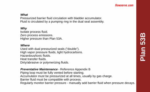
WhatPressurized barrier fluid circulation with bladder accumulator.Fluid is circulated by a pumping ring in the dual seal assembly.
WhyIsolate process fluid.Zero process emissions.Higher pressure than Plan 53A.
WhereUsed with dual pressurized seals (“double”).High vapor pressure fluids, light hydrocarbons.Hazardous/toxic fluids.Heat transfer fluids.Dirty/abrasive or polymerizing fluids.
Preventative Maintenance - Reference Appendix BPiping loop must be fully vented before starting.Accumulator must be pressurized at all times, usually by gas charge.Barrier fluid must be compatible with process.Regularly monitor barrier pressure - manually add barrier fluid when pressure decays.
sealend view
Pla
n 5
3C
outlet
inlet
vent,normally closed
pressure indicator (low)
pressure switch
level switch (low)
cooling in
drain,normallyclosed
cooling out
liquid fill,normally closed
level indicator
coolingcoils
pressure reliefvalve
temperatureindicator
flowserve.com
Pla
n 5
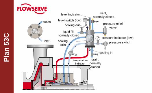
3C
WhatPressurized barrier fluid circulation with piston accumulator.Fluid is circulated by a pumping ring in the dual seal assembly.
WhyIsolate process fluid.Zero process emissions.Higher pressure than Plan 53A.Dynamic tracking of system pressure.
WhereUsed with dual pressurized seals (“double”).High vapor pressure fluids, light hydrocarbons.Hazardous/toxic fluids.Heat transfer fluids.
Preventative Maintenance - Reference Appendix BPiping loop must be fully vented before starting.Reference line must tolerate process contamination without plugging.Barrier fluid must be compatible with process.Reservoir level indicator indicates both inboard and outboard seal leakage.
Pla
n 5
4
sealend view
outlet
inlet
from / to external
circulating system
flowserve.com
Pla
n 5
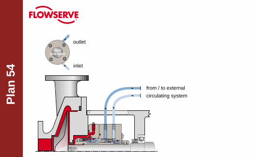
4
WhatPressurized barrier fluid circulation by external system.
WhyIsolate process fluid.Zero process emissions.Seal cannot induce circulation.
WhereUsed with dual pressurized seals (“double”).High vapor pressure fluids, light hydrocarbons.Hazardous/toxic fluids.Heat transfer fluids.Dirty/abrasive or polymerizing fluids.Mixers/agitators.
Preventative MaintenancePiping loop must be fully vented before starting.Circulating system must be pressurized and energized at all times.Barrier fluid must be compatible with process.Circulating system level indicator shows both inboard and outboard seal leakage.
sealend view
Pla
n 6
2
inlet
drain
pressureindicator(optional) steam trap
(steam quench)
quench,normally
open
drain,normally
opencheck valve
flowserve.com
Pla
n 6
2
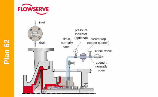
WhatExternal quench on atmospheric side of seal.Quench fluids typically steam, nitrogen, or water.
WhyPrevent solids buildup on atmospheric side of seal.Prevent icing.
WhereUsed with single seals.Oxidizing fluids or fluids that coke, hot hydrocarbons.Crystallizing fluids or fluids that salt out.Caustic.Cold fluids less than 32° F (0° C).
Preventative MaintenanceQuench inlet should be on top of gland with outlet/drain on bottom.Quench pressure should be limited to 3 psi (0.2 bar) or less.Use throttle bushing on atmospheric side of seal to direct quench flow to seal drain.Monitor regularly, checking for closed valves, blocked lines, and steam trap condition.
Pla
n 6
5
Drai
n - s
ee e
nd v
iew
for p
rope
r orie
ntat
ion
sealend view
drain,normally
open
orifice
bypassline
blockvalve,
normallyopen
levelswitch(high)
overflowchamber
flowserve.com
Pla
n 6
5
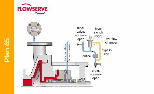
WhatExternal drain with leakage detection on atmospheric side of seal.
WhyMay be used alone or with Plan 62 quench.Used with close clearance throttle bushing.Useful with single seals in remote locations.
WhereLeakage collection for process leakage or quench fluid.Safety indicator for primary seal.
Preventative MaintenanceDrain must be on bottom of gland with downward-sloped piping.Continuously drain to liquid recovery system.Orifice downstream of level switch typically 1/4” (5 mm) must be oriented vertically.Bypass line from overflow chamber must re-enter below orifice.Piping may require heat tracing when used with solidifying fluids.Monitor regularly, checking for closed valves, blocked lines, and working level switch.
sealend view
Pla
n 7
2
vent
drain
inlet
1
3
2 C
D
AB
E
F
HG
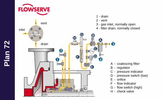
1 - drain2 - vent3 - gas inlet, normally open4 - filter drain, normally closed
4A - coalescing filterB - regulatorC - pressure indicatorD - pressure switch (low)E - orificeF - flow indicatorG - flow switch (high)H - check valve
flowserve.com
Pla
n 7
2
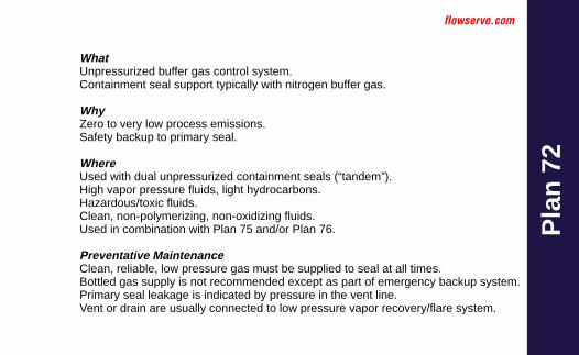
WhatUnpressurized buffer gas control system.Containment seal support typically with nitrogen buffer gas.
WhyZero to very low process emissions.Safety backup to primary seal.
WhereUsed with dual unpressurized containment seals (“tandem”).High vapor pressure fluids, light hydrocarbons.Hazardous/toxic fluids.Clean, non-polymerizing, non-oxidizing fluids.Used in combination with Plan 75 and/or Plan 76.
Preventative MaintenanceClean, reliable, low pressure gas must be supplied to seal at all times.Bottled gas supply is not recommended except as part of emergency backup system.Primary seal leakage is indicated by pressure in the vent line.Vent or drain are usually connected to low pressure vapor recovery/flare system.
sealend view
Pla
n 7
4 drain
inlet
1
3
2
C
D
A B
EFG
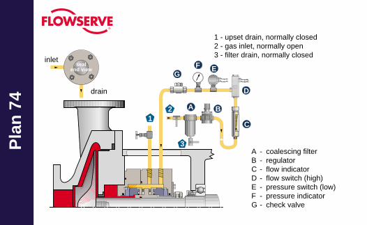
1 - upset drain, normally closed2 - gas inlet, normally open3 - filter drain, normally closed
A - coalescing filterB - regulatorC - flow indicatorD - flow switch (high)E - pressure switch (low)F - pressure indicatorG - check valve
flowserve.com
Pla
n 7
4
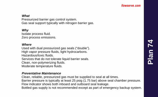
WhatPressurized barrier gas control system.Gas seal support typically with nitrogen barrier gas.
WhyIsolate process fluid.Zero process emissions.
WhereUsed with dual pressurized gas seals (“double”).High vapor pressure fluids, light hydrocarbons.Hazardous/toxic fluids.Services that do not tolerate liquid barrier seals.Clean, non-polymerizing fluids.Moderate temperature fluids.
Preventative MaintenanceClean, reliable, pressurized gas must be supplied to seal at all times.Barrier pressure is typically at least 25 psig (1.75 bar) above seal chamber pressure.Flow indicator shows both inboard and outboard seal leakage.Bottled gas supply is not recommended except as part of emergency backup system.
Drai
n - s
ee e
nd v
iew
for p
rope
r orie
ntat
ion
sealend view
Pla
n 7
5 drain
pressure switch(high)
pressureindicator
vent,normally
open
orifice
level switch (high)
drain,normallyclosed
reservoir locatedbelow seal drain port
isloationvalve
levelindicator
flowserve.com
Pla
n 7
5
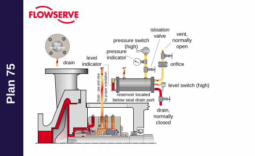
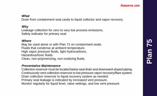
WhatDrain from containment seal cavity to liquid collector and vapor recovery.
WhyLeakage collection for zero to very low process emissions.Safety indicator for primary seal.
WhereMay be used alone or with Plan 72 on containment seals.Fluids that condense at ambient temperature.High vapor pressure fluids, light hydrocarbons.Hazardous/toxic fluids.Clean, non-polymerizing, non-oxidizing fluids.
Preventative MaintenanceCollection reservoir must be located below seal drain and downward-sloped piping.Continuously vent collection reservoir to low pressure vapor recovery/flare system.Drain collection reservoir to liquid recovery system as needed.Primary seal leakage is indicated by increased vent pressure.Monitor regularly for liquid level, valve settings, and low vent pressure.
Pla
n 7
6
sealend view
vent
drain
vent,normally
open
pressure indicator
pressure switch (high)
drain,normallyclosed
drain,normallyclosed
orifice
flowserve.com
Pla
n 7
6
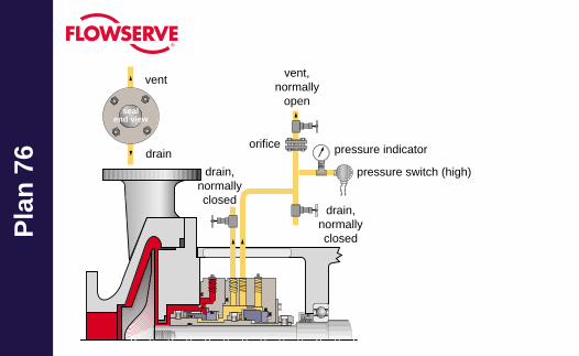
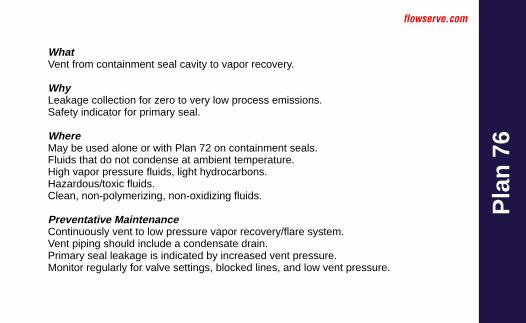
WhatVent from containment seal cavity to vapor recovery.
WhyLeakage collection for zero to very low process emissions.Safety indicator for primary seal.
WhereMay be used alone or with Plan 72 on containment seals.Fluids that do not condense at ambient temperature.High vapor pressure fluids, light hydrocarbons.Hazardous/toxic fluids.Clean, non-polymerizing, non-oxidizing fluids.
Preventative MaintenanceContinuously vent to low pressure vapor recovery/flare system.Vent piping should include a condensate drain.Primary seal leakage is indicated by increased vent pressure.Monitor regularly for valve settings, blocked lines, and low vent pressure.
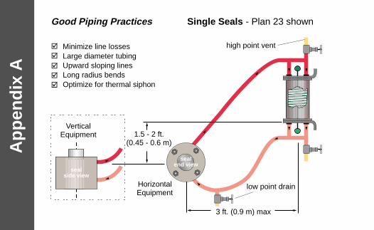
sealside view
sealend view
3 ft. (0.9 m) max
1.5 - 2 ft.(0.45 - 0.6 m)
Minimize line lossesLarge diameter tubingUpward sloping linesLong radius bendsOptimize for thermal siphon
high point vent
low point drain
VerticalEquipment
HorizontalEquipment
Ap
pen
dix
AGood Piping Practices Single Seals - Plan 23 shown
�
�
�
�
�
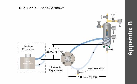
sealside view
sealend view
Ap
pen
dix
B
Dual Seals - Plan 53A shown
4 ft. (1.2 m) max
low point drain
VerticalEquipment
HorizontalEquipment
1.5 - 2 ft.(0.45 - 0.6 m)
Acc
esso
ries
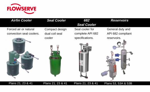
Airfin CoolersTM
Forced air or naturalconvection seal coolers.
Reservoirs
General duty andAPI 682 compliantreservoirs.
Seal Cooler
Compact designdual coil sealcooler
Plans 21, 23 & 41 Plans 21, 23 & 41 Plans 21, 23 & 41
682Seal Cooler
Seal cooler forcomplete API 682specifications.
Plans 53, 53A & 53B
flowserve.com
Acc
esso
ries
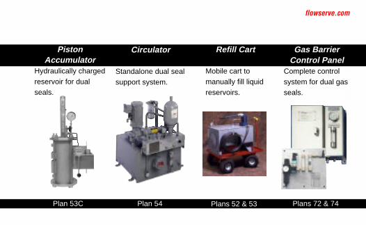
Circulator
Standalone dual sealsupport system.
Gas BarrierControl Panel
Complete controlsystem for dual gasseals.
Refill Cart
Mobile cart tomanually fill liquidreservoirs.
Plan 54 Plans 52 & 53 Plans 72 & 74
PistonAccumulator
Hydraulically chargedreservoir for dualseals.
Plan 53C
Acc
esso
ries
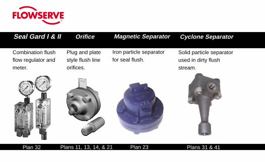
Orifice
Plug and platestyle flush lineorifices.
Magnetic Separator
Iron particle separatorfor seal flush.
Plans 11, 13, 14, & 21 Plans 31 & 41
Cyclone Separator
Solid particle separatorused in dirty flushstream.
Plan 23
Seal Gard I & II
Combination flushflow regulator andmeter.
Plan 32
flowserve.com
Acc
esso
ries
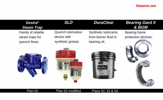
Gestra®
Steam TrapFamily of reliablesteam traps forquench flows.
Bearing Gard II& BGM
Bearing frameprotection devices.
SLD
Quench lubricationdevice withsynthetic grease.
Plan 62 Plan 62 modified
DuraClear
Synthetic lubricantsfrom barrier fluid tobearing oil.
Plans 52, 53 & 54

No
tes

No
tes

No
tes

No
tes
USA and CanadaFlowserve CorporationFlow SolutionsKalamazoo, Michigan USATelephone: 1 269 381 2650Telefax: 1 269 382 8726
Europe, Middle East, AfricaFlowserve CorporationFlow SolutionsRoosendaal, The NetherlandsTelephone: 31 165 581400Telefax: 31 165 552622Asia PacificFlowserve CorporationFlow SolutionsSingaporeTelephone: 65 684 65100Telefax: 65 674 71963Latin AmericaFlowserve CorporationFlow SolutionsMexico CityTelephone: 52 55 5567 7170Telefax: 52 55 5567 4224
To find your local Flowserve representativeand find out more about FlowserveCorporation visit www.flowserve.com
FTA160 REV 01-05 Printed in USA
Flowserve Corporation has established industry leadership in the design and manufacture of its products. When properly selected, this Flowserveproduct is designed to perform its intended function safely during its useful life. However, the purchaser or user of Flowserve products should beaware that Flowserve products might be used in numerous applications under a wide variety of industrial service conditions. Although Flowservecan provide general guidelines, it cannot provide specific data and warnings for all possible applications. The purchaser/user must thereforeassume the ultimate responsibility for the proper sizing and selection, installation, operation, and maintenance of Flowserve products. The purchaser/user should read and understand the Installation Instructions included with the product, and train its employees and contractors in the safe use ofFlowserve products in connection with the specific application.
While the information and specifications contained in this literature are believed to be accurate, they are supplied for informative purposes only and should notbe considered certified or as a guarantee of satisfactory results by reliance thereon. Nothing contained herein is to be construed as a warranty or guarantee,express or implied, regarding any matter with respect to this product. Because Flowserve is continually improving and upgrading its product design, thespecifications, dimensions and information contained herein are subject to change without notice. Should any question arise concerning these provisions, thepurchaser/user should contact Flowserve Corporation at any one of its worldwide operations or offices.