flow regulators with electric actuator - samson · pdf fileflow regulators with electric...
TRANSCRIPT
Mounting and Operating Instructions
EB 3135-1 EN Edition July 2016
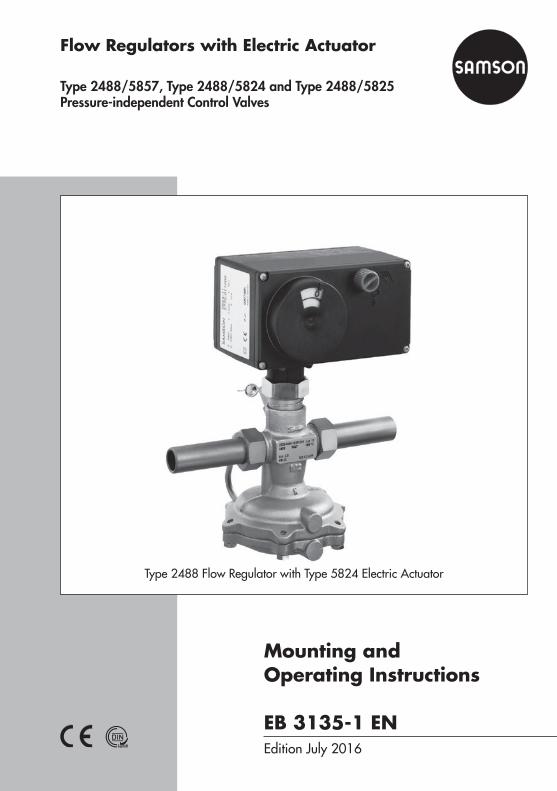
Flow Regulators with Electric Actuator
Type 2488/5857, Type 2488/5824 and Type 2488/5825 Pressure-independent Control Valves
Type 2488 Flow Regulator with Type 5824 Electric Actuator
Definition of signal words
DANGER!Hazardous situations which, if not avoided, will result in death or seri-ous injury
WARNING!Hazardous situations which, if not avoided, could result in death or seri-ous injury
NOTICEProperty damage message or mal-function
Note:Additional information
Tip:Recommended action
2 EB 3135-1 EN
Note on these mounting and operating instructions
These mounting and operating instructions assist you in mounting and operating the device safely. The instructions are binding for handling SAMSON devices.
Î For the safe and proper use of these instructions, read them carefully and keep them for later reference.
Î If you have any questions about these instructions, contact SAMSON‘s After-sales Service Department ([email protected]).
The mounting and operating instructions for the devices are included in the scope of delivery. The latest documentation is available on our website (www.samson.de) > Product documentation. You can enter the document number or type number in the [Find:] field to look for a document.
Contents
EB 3135-1 EN 3
1 General safety instructions .............................................................................42 Process medium and scope of application .......................................................52.1 Transportation and storage .............................................................................53 Design and principle of operation ..................................................................54 Installation ....................................................................................................64.1 Mounting position ..........................................................................................64.2 Strainer .........................................................................................................64.3 Additional installation instructions ...................................................................85 Operation .....................................................................................................85.1 Start-up .........................................................................................................85.2 Set point adjustment .......................................................................................85.2.1 Adjustment without actuator ............................................................................85.2.2 Adjustment with electric actuator ...................................................................115.2.3 Adjustment with Type 5857 or Type 5824 Actuator ........................................115.2.4 Adjustment with Type 5825 Actuator .............................................................126 Maintenance – Replacing parts ....................................................................126.1 Replacing the restriction ................................................................................136.2 Cleaning or replacing the plug ......................................................................136.3 Replacing the diaphragm .............................................................................147 Troubleshooting...........................................................................................158 Nameplate ..................................................................................................169 Customer service .........................................................................................1610 Dimensions .................................................................................................1711 Technical data .............................................................................................19
4 EB 3135-1 EN
General safety instructions
1 General safety instructions − The regulators are to be mounted, started up or serviced by fully trained and
qualified personnel only; the accepted industry codes and practices are to be observed. Make sure employees or third persons are not exposed to any danger.
− All safety instructions and warnings given in these mounting and operating instructions, particularly those concerning installation, start-up and mainte-nance, must be strictly observed.
− According to these mounting and operating instructions, trained personnel refers to individuals who are able to judge the work they are assigned to and recognize possible dangers due to their specialized training, their knowledge and experience as well as their knowledge of the applicable standards.
− The regulators comply with the requirements of the European Pressure Equip-ment Directive 2014/68/EU. The EU declaration of conformity issued for a regulator bearing the CE marking includes information on the applied con-formity assessment procedure. The declaration of conformity can be provided on request.
− To ensure appropriate use, only use the regulator in applications where the operating pressure and temperatures do not exceed the specifications used for sizing the regulator at the ordering stage.
− The manufacturer does not assume any responsibility for damage caused by external forces or any other external factors.
− Any hazards that could be caused in the regulator by the process medium, operating pressure or by moving parts are to be prevented by means of the appropriate measures.
− Proper transport, storage, installation, operation and maintenance are as-sumed.
Note: Non-electric actuators and control valve versions do not have their own potential ignition source according to the ignition risk assessment stipulated in EN 13463-1: 2009, section 5.2, even in the rare incident of an operating fault. Therefore, they do not fall within the scope of Directive 2014/34/EU. For connection to the equipotential bonding system, observe the requirements specified in section 6.4 of EN 60079-14: 2014 (VDE 0165 Part 1).
EB 3135-1 EN 5
Process medium and scope of application
2 Process medium and scope of applicationPressure-independent control valves for controlling the flow rate in district heating systems. Combined with an electric actuator used to transmit the control signal of an electric control device. Suitable for liquids up to 150 °C.Install the regulator preferably in the return flow pipe of the plant.
NOTICEThe regulator is not a safety valve. If necessary, a suitable overpressure protection must be installed on site in the plant section.
2.1 Transportation and storageThe regulator must be carefully handled, transported, and stored. Protect the regulator against adverse influences, such as dirt, moisture or frost, during storage and transportation.
3 Design and principle of operationSee Fig. 1 on page 7.These combined regulators consist of a valve, a diaphragm actuator, and an adjustable re-striction (orifice) with an electric actuator (Type 5857, Type 5824 or Type 5825) connected to it.As a result, it is possible to transmit the control signal of an electric control device to achieve additional temperature control by changing the restriction position.A maximum flow rate can be adjusted mechanically at the restriction (orifice).The Type 2488/... Regulator closes when the flow rate rises and/or when the output signal issued by the electric control device increases.
6 EB 3135-1 EN
Installation
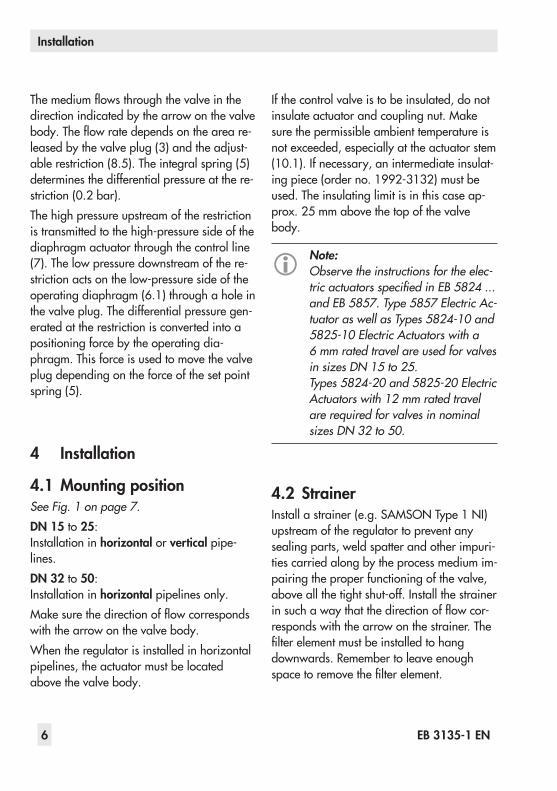
The medium flows through the valve in the direction indicated by the arrow on the valve body. The flow rate depends on the area re-leased by the valve plug (3) and the adjust-able restriction (8.5). The integral spring (5) determines the differential pressure at the re-striction (0.2 bar).The high pressure upstream of the restriction is transmitted to the high-pressure side of the diaphragm actuator through the control line (7). The low pressure downstream of the re-striction acts on the low-pressure side of the operating diaphragm (6.1) through a hole in the valve plug. The differential pressure gen-erated at the restriction is converted into a positioning force by the operating dia-phragm. This force is used to move the valve plug depending on the force of the set point spring (5).
4 Installation
4.1 Mounting positionSee Fig. 1 on page 7.DN 15 to 25: Installation in horizontal or vertical pipe-lines.DN 32 to 50: Installation in horizontal pipelines only.Make sure the direction of flow corresponds with the arrow on the valve body.When the regulator is installed in horizontal pipelines, the actuator must be located above the valve body.
If the control valve is to be insulated, do not insulate actuator and coupling nut. Make sure the permissible ambient temperature is not exceeded, especially at the actuator stem (10.1). If necessary, an intermediate insulat-ing piece (order no. 1992-3132) must be used. The insulating limit is in this case ap-prox. 25 mm above the top of the valve body.
Note:Observe the instructions for the elec-tric actuators specified in EB 5824 ... and EB 5857. Type 5857 Electric Ac-tuator as well as Types 5824-10 and 5825-10 Electric Actuators with a 6 mm rated travel are used for valves in sizes DN 15 to 25. Types 5824-20 and 5825-20 Electric Actuators with 12 mm rated travel are required for valves in nominal sizes DN 32 to 50.
4.2 StrainerInstall a strainer (e.g. SAMSON Type 1 NI) upstream of the regulator to prevent any sealing parts, weld spatter and other impuri-ties carried along by the process medium im-pairing the proper functioning of the valve, above all the tight shut-off. Install the strainer in such a way that the direction of flow cor-responds with the arrow on the strainer. The filter element must be installed to hang downwards. Remember to leave enough space to remove the filter element.
EB 3135-1 EN 7
Installation
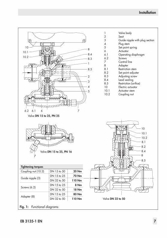
Fig. 1: Functional diagrams
10
8.31
8.5
3
54
8.4
810.1
10.2
6.2
2
6 76.1
7
Valve DN 15 to 25, PN 25
Valve DN 32 to 50
1 Valve body2 Seat3 Guide nipple with plug section4 Plug stem5 Set point spring6 Actuator6.1 Operating diaphragm6.2 Screws7 Control line8 Adapter8.1 Restriction stem8.2 Set point adjuster8.3 Adjusting screw8.4 Lead sealing8.5 Restriction (orifice)10 Electric actuator10.1 Actuator stem10.2 Coupling nut
10.110
10.28.18.28.48
8.5
Tightening torquesCoupling nut (10.2) DN 15 to 50 20 Nm
Guide nipple (3)DN 15 to 25 70 NmDN 32 to 50 110 Nm
Screws (6.2)DN 15 to 25 8 NmDN 32 to 50 18 Nm
Adapter (8)DN 15 to 25 80 NmDN 32 to 50 110 Nm
Valve DN 15 to 25, PN 16
8 EB 3135-1 EN
Operation
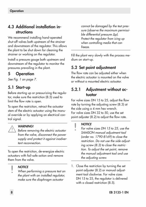
4.3 Additional installation in-structions
We recommend installing hand-operated shut-off valves both upstream of the strainer and downstream of the regulator. This allows the plant to be shut down for cleaning the strainer or working on the regulator.Install a pressure gauge both upstream and downstream of the regulator to monitor the pressures prevailing in the plant.
5 OperationSee Fig. 1 on page 7.
5.1 Start-upBefore starting up or pressurizing the regula-tor, make sure the restriction (8.5) used to limit the flow rate is open.To open the restriction, retract the actuator stem of the electric actuator using the manu-al override or by applying an electrical con-trol signal.
WARNING!Before removing the electric actuator from the valve, disconnect the power supply and protect it against inadver-tent reconnection.
To open the restriction, de-energize electric actuators with fail-safe action and remove them from the valve.
NOTICEWhen performing a pressure test on the plant with an installed regulator, make sure the diaphragm actuator
cannot be damaged by the test pres-sure (observe the maximum permissi-ble differential pressure ∆p).Protect the regulator from icing up when controlling media that can freeze.
Fill the plant very slowly with the process me-dium on start-up.
5.2 Set point adjustmentThe flow rate can be adjusted either when the electric actuator is mounted on the valve or without a mounted electric actuator.
5.2.1 Adjustment without ac-tuator
For valve sizes DN 15 to 25, adjust the flow rate by turning the adjusting screw (8.3) at the side using a 4 mm hex wrench. For valve sizes DN 32 to 50, use the set point adjuster (8.2) to adjust the flow rate.
NOTICEFor valve sizes DN 15 to 25, use the SAMSON manual adjustment tool (order no. 1790-8169) to close the restriction. Do not use the side adjust-ing screw (8.3) to close the restric-tion. To adjust the set point, remove the manual adjustment tool and use the adjusting screw.
1. Close the restriction by turning the set point adjuster (8.2) or manual adjust-ment tool clockwise. For valve sizes DN 15 to 25, the regulator is delivered with a closed restriction (8.5).
EB 3135-1 EN 9
Operation
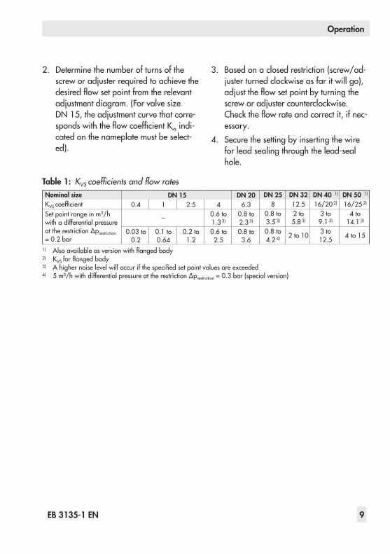
2. Determine the number of turns of the screw or adjuster required to achieve the desired flow set point from the relevant adjustment diagram. (For valve size DN 15, the adjustment curve that corre-sponds with the flow coefficient Kvs indi-cated on the nameplate must be select-ed).
3. Based on a closed restriction (screw/ad-juster turned clockwise as far it will go), adjust the flow set point by turning the screw or adjuster counterclockwise. Check the flow rate and correct it, if nec-essary.
4. Secure the setting by inserting the wire for lead sealing through the lead-seal hole.
Table 1: KVS coefficients and flow ratesNominal size DN 15 DN 20 DN 25 DN 32 DN 40 1) DN 50 1)
KVS coefficient 0.4 1 2.5 4 6.3 8 12.5 16/20 2) 16/25 2)
Set point range in m3/h with a differential pressure at the restriction ∆prestriction = 0.2 bar
– 0.6 to 1.3 3)
0.8 to 2.3 3)
0.8 to 3.5 3)
2 to 5.8 3)
3 to 9.1 3)
4 to 14.1 3)
0.03 to 0.2
0.1 to 0.64
0.2 to 1.2
0.6 to 2.5
0.8 to 3.6
0.8 to 4.2 4) 2 to 10 3 to
12.5 4 to 15
1) Also available as version with flanged body2) KVS for flanged body 3) A higher noise level will occur if the specified set point values are exceeded 4) 5 m³/h with differential pressure at the restriction ∆prestriction = 0.3 bar (special version)

10 EB 3135-1 EN
Operation
Fig. 2: Flow rate diagram for DN 15 to 25 · Differential pressure at the restriction ∆prestriction = 0.2 bar
*) With ∆prestriction = 0.3 bar
Travel in mmTurns of adjusting screw
0.01 0.05 0.1 0.5 1 50
2
1
3
4
DN 15
V
m³/h0.02 0.03 0.2 0.3 2 3 4
1.75
5
4
3
3.5
5.5
6.5
4.5
2.5
2
1
0
7
6KVS 0.4 KVS 2.5 KVS 4
DN 25,KVS 8
DN 25,KVS 8*
DN 20,KVS 6.3
KVS 1
EB 3135-1 EN 11
Operation
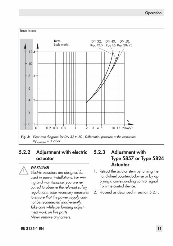
Fig. 3: Flow rate diagram for DN 32 to 50 · Differential pressure at the restriction ∆prestriction = 0.2 bar
5.2.2 Adjustment with electric actuator
WARNING!Electric actuators are designed for used in power installations. For wir-ing and maintenance, you are re-quired to observe the relevant safety regulations. Take necessary measures to ensure that the power supply can-not be reconnected inadvertently. Take care while performing adjust-ment work on live partsNever remove any covers.
Turns Scale marks
Travel in mm
0.1 0.5 1 5 101
2
3
4
DN 32,KVS 12.5
DN 40,KVS 16
DN 50,KVS 20/25
V
m³/h0.2 0.3 2 3 4 15 20
8
2
0
4
6
10
12
5.2.3 Adjustment with Type 5857 or Type 5824 Actuator
1. Retract the actutor stem by turning the handwheel counterclockwise or by ap-plying a corresponding control signal from the control device.
2. Proceed as described in section 5.2.1.
12 EB 3135-1 EN
Maintenance – Replacing parts
5.2.4 Adjustment with Type 5825 Actuator
1. Switch the control device to manual mode and change the control signal to retract the actuator stem all the way and compress the spring mechanism.
If there is no control signal, the actuator can be adjusted manually. For manual adjust-ment, remove the front case cover. Place a 4 mm hex wrench on the red actuating shaft and turn it. Only turn the shaft counterclock-wise and only up to the point at which the torque switch in the actuator is activated.Once the magnet has been released, the spring mechanism pushes the actuator stem back to the fail-safe position.
WARNING!Observe the relevant safety regula-tions on connecting the electric actu-ator or performing any maintenance on it.
2. Proceed as described in section 5.2.1 on page 8.
Note:The flow rate indicated in the dia-gram is reduced by approximately 20 % for valves in sizes DN 32 to 50 which are combined with Type 5821/5822 Actuators.
6 Maintenance – Replacing parts
See Fig. 1 on page 7.The flow regulator does not require any maintenance. Nevertheless, it is subject to natural wear, particularly at the seat, plug and operating diaphragm. Depending on the operating conditions that prevail, inspect the regulator at regular intervals to avoid possible malfunctions.
NOTICEPrior to carrying out any mainte-nance work on the flow regulator, it must be removed from the pipeline. Before performing any work on the regulator, make sure the relevant sec-tion of the plant has been depressur-ized and, depending on the process medium, drained as well.Depending on the field of applica-tion, allow the regulator to cool down or warm up to reach ambient tem-perature prior to starting any work on it.
If the valve does not close tightly, this may be caused by a dirty seat and plug or due to wear.If the flow rate deviates considerably from the adjusted set point, e.g. rapidly increas-ing flow rate, check the operating dia-phragm for ruptures and replace it, if neces-sary.
EB 3135-1 EN 13
Maintenance – Replacing parts
WARNING!Before removing the electric actuator from the valve, disconnect the power supply and protect it against inadver-tent reconnection.
6.1 Replacing the restriction1. Unscrew the coupling nut (10.2). Remove
the actuator from the connecting part of the valve.
NOTICEFor valve sizes DN 15 to 25: Un-screw the adjusting screw (8.3) be-fore removing the adapter.
2. Use a socket wrench (order no. 1280-3001, refer to section 6.2 on page 13) to unscrew the adapter (8) of the restriction and pull it out of the valve body.
3. Replace parts and reassemble in reverse order. Observe the tightening torques specified in the table in Fig. 1.
6.2 Cleaning or replacing the plug
1. Unscrew the coupling nut. Remove the actuator from the connecting part of the valve.
2. Unscrew the control line (7).3. Unscrew the screws (6.2). Remove the
bottom diaphragm case together with the
operating diaphragm (6.1) and dia-phragm plate.
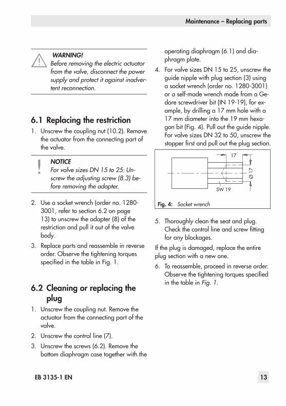
4. For valve sizes DN 15 to 25, unscrew the guide nipple with plug section (3) using a socket wrench (order no. 1280-3001) or a self-made wrench made from a Ge-dore screwdriver bit (IN 19-19), for ex-ample, by drilling a 17 mm hole with a 17 mm diameter into the 19 mm hexa-gon bit (Fig. 4). Pull out the guide nipple. For valve sizes DN 32 to 50, unscrew the stopper first and pull out the plug section.
17
Ø 1
7
SW 19
Fig. 4: Socket wrench
5. Thoroughly clean the seat and plug. Check the control line and screw fitting for any blockages.
If the plug is damaged, replace the entire plug section with a new one.6. To reassemble, proceed in reverse order.
Observe the tightening torques specified in the table in Fig. 1.
14 EB 3135-1 EN
Maintenance – Replacing parts
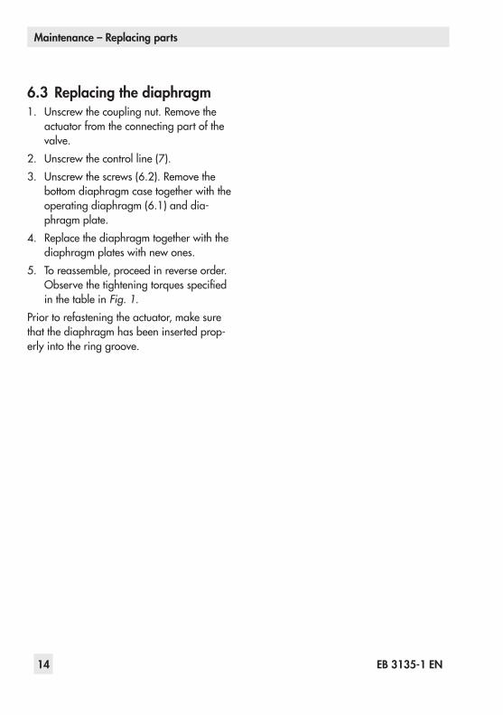
6.3 Replacing the diaphragm1. Unscrew the coupling nut. Remove the
actuator from the connecting part of the valve.
2. Unscrew the control line (7).3. Unscrew the screws (6.2). Remove the
bottom diaphragm case together with the operating diaphragm (6.1) and dia-phragm plate.
4. Replace the diaphragm together with the diaphragm plates with new ones.
5. To reassemble, proceed in reverse order. Observe the tightening torques specified in the table in Fig. 1.
Prior to refastening the actuator, make sure that the diaphragm has been inserted prop-erly into the ring groove.
EB 3135-1 EN 15
Troubleshooting
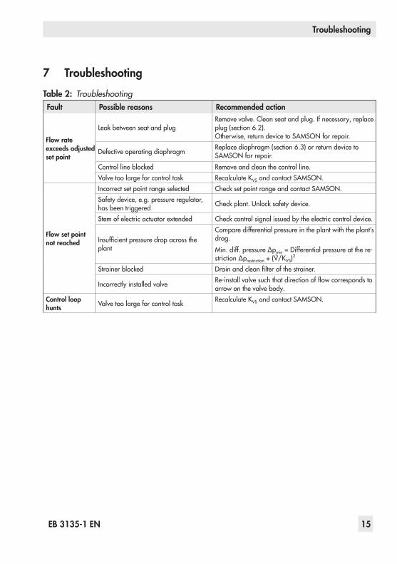
7 TroubleshootingTable 2: TroubleshootingFault Possible reasons Recommended action
Flow rate exceeds adjusted set point
Leak between seat and plugRemove valve. Clean seat and plug. If necessary, replace plug (section 6.2). Otherwise, return device to SAMSON for repair.
Defective operating diaphragm Replace diaphragm (section 6.3) or return device to SAMSON for repair.
Control line blocked Remove and clean the control line.Valve too large for control task Recalculate KVS and contact SAMSON.
Flow set point not reached
Incorrect set point range selected Check set point range and contact SAMSON.Safety device, e.g. pressure regulator, has been triggered Check plant. Unlock safety device.
Stem of electric actuator extended Check control signal issued by the electric control device.
Insufficient pressure drop across the plant
Compare differential pressure in the plant with the plant’s drag.Min. diff. pressure ∆pmin = Differential pressure at the re-striction ∆prestriction + (V/KVS)
2
Strainer blocked Drain and clean filter of the strainer.
Incorrectly installed valve Re-install valve such that direction of flow corresponds to arrow on the valve body.
Control loop hunts Valve too large for control task Recalculate KVS and contact SAMSON.
∙
16 EB 3135-1 EN
Nameplate
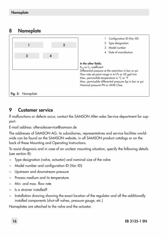
8 Nameplate
Fig. 5: Nameplate
9 Customer serviceIf malfunctions or defects occur, contact the SAMSON After-sales Service department for sup-port.E-mail address: [email protected] addresses of SAMSON AG, its subsidiaries, representatives and service facilities world-wide can be found on the SAMSON website, in all SAMSON product catalogs or on the back of these Mounting and Operating Instructions.To assist diagnosis and in case of an unclear mounting situation, specify the following details (see section 8): − Type designation (valve, actuator) and nominal size of the valve − Model number and configuration ID (Var.-ID) − Upstream and downstream pressure − Process medium and its temperature − Min. and max. flow rate − Is a strainer installed? − Installation drawing showing the exact location of the regulator and all the additionally
installed components (shut-off valves, pressure gauge, etc.)Nameplates are attached to the valve and the actuator.
1 Configuration ID (Var.-ID)2 Type designation3 Model number4 Date of manufacture
In the other fields:KVS or CV coefficientDifferential pressure at the restriction in bar or psiFlow rate set point range in m³/h or US gal/minMax. permissible temperature in °C or °FMax. permissible differential pressure ∆p in bar or psiNominal pressure PN or ANSI Class
2
3 4
1
EB 3135-1 EN 17
Dimensions
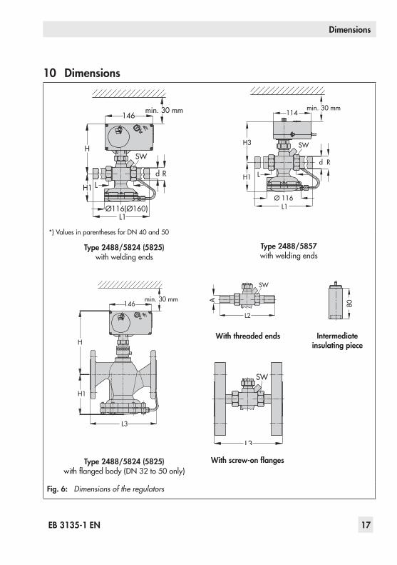
10 Dimensions
Fig. 6: Dimensions of the regulators
80
L3
SW
Type 2488/5824 (5825) with welding ends
SW
1466
d R
H
H1 L
L1Ø116(Ø160)
min. 30 mm
1466
L3
H1
H
min. 30 mm
Type 2488/5857 with welding ends
Type 2488/5824 (5825) with flanged body (DN 32 to 50 only)
With threaded ends
With screw-on flanges
L2
SW
A
*) Values in parentheses for DN 40 and 50
Intermediate insulating piece
min. 30 mm
Rd
H3
H1 L
L1Ø 116
114
SW
18 EB 3135-1 EN
Dimensions
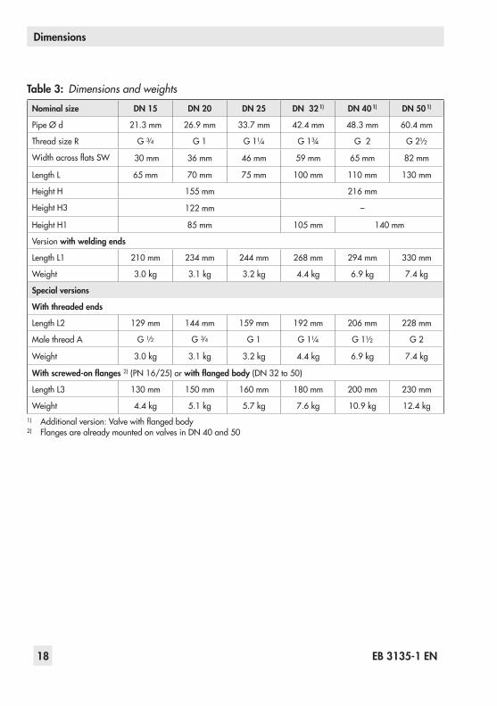
Table 3: Dimensions and weights
Nominal size DN 15 DN 20 DN 25 DN 32 1) DN 40 1) DN 50 1)
Pipe Ø d 21.3 mm 26.9 mm 33.7 mm 42.4 mm 48.3 mm 60.4 mm
Thread size R G 3/4 G 1 G 1¼ G 1¾ G 2 G 2½
Width across flats SW 30 mm 36 mm 46 mm 59 mm 65 mm 82 mm
Length L 65 mm 70 mm 75 mm 100 mm 110 mm 130 mm
Height H 155 mm 216 mm
Height H3 122 mm –
Height H1 85 mm 105 mm 140 mm
Version with welding ends
Length L1 210 mm 234 mm 244 mm 268 mm 294 mm 330 mm
Weight 3.0 kg 3.1 kg 3.2 kg 4.4 kg 6.9 kg 7.4 kg
Special versions
With threaded ends
Length L2 129 mm 144 mm 159 mm 192 mm 206 mm 228 mm
Male thread A G 1/2 G 3/4 G 1 G 1¼ G 1½ G 2
Weight 3.0 kg 3.1 kg 3.2 kg 4.4 kg 6.9 kg 7.4 kg
With screwed-on flanges 2) (PN 16/25) or with flanged body (DN 32 to 50)
Length L3 130 mm 150 mm 160 mm 180 mm 200 mm 230 mm
Weight 4.4 kg 5.1 kg 5.7 kg 7.6 kg 10.9 kg 12.4 kg1) Additional version: Valve with flanged body2) Flanges are already mounted on valves in DN 40 and 50
EB 3135-1 EN 19
Technical data
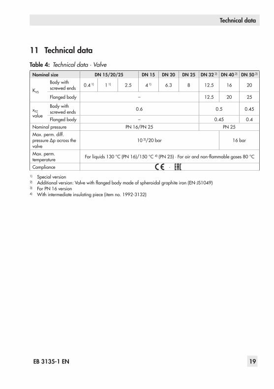
11 Technical dataTable 4: Technical data · Valve
Nominal size DN 15/20/25 DN 15 DN 20 DN 25 DN 32 2) DN 40 2) DN 50 2)
KVS
Body with screwed ends 0.4 1) 1 1) 2.5 4 1) 6.3 8 12.5 16 20
Flanged body – 12.5 20 25
xFZ value
Body with screwed ends 0.6 0.5 0.45
Flanged body – 0.45 0.4Nominal pressure PN 16/PN 25 PN 25Max. perm. diff. pressure ∆p across the valve
10 3)/20 bar 16 bar
Max. perm. temperature For liquids 130 °C (PN 16)/150 °C 4) (PN 25) ∙ For air and non-flammable gases 80 °C
Compliance ·
1) Special version2) Additional version: Valve with flanged body made of spheroidal graphite iron (EN-JS1049)3) For PN 16 version4) With intermediate insulating piece (item no. 1992-3132)
20 EB 3135-1 EN
Technical data
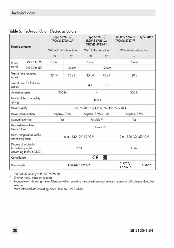
Table 5: Technical data · Electric actuators
Electric actuator
Type 5824-.../ TROVIS 5724-...1)
Type 5825-.../ TROVIS 5725-.../ TROVIS 5725-71)
TROVIS 5757-3 TROVIS 5757-71)
Type 5857
Without fail-safe action With fail-safe action Without fail-safe action
10 20 10 20 –
Rated travel
DN 15 to 25 6 mm – 6 mm – 6 mm
DN 32 to 50 – 12 mm – 12 mm –
Transit time for rated travel 35 s 2) 70 s 2) 35 s 2) 70 s 2) 20 s
Transit time for fail-safe action – 4 s 8 s –
Actuating force 700 N – 300 N
Nominal thrust of safety spring – 500 N –
Power supply 230 V, 50 Hz (24 V, 50/60 Hz; 24 V DC)
Power consumption Approx. 3 VA Approx. 3 VA +1 VA Approx. 3 VA
Manual override Yes Possible 3) Yes
Permissible ambient temperature 0 to +50 °C
Perm. temperature at the connecting stem 0 to +130 °C/150 °C 4) 0 to +120 °C/150 °C 4)
Degree of protection (installed upright, according to EN 60529)
IP 54 IP 42
Compliance ·
Data sheets T 5724/T 5725-7 T 5757/ T 5757-7 T 5857
1) TROVIS 57xx only with 230 V/50 Hz2) Shorter transit times on request3) Manual override using 4 mm Allen key (after removing the cover); actuator always returns to fail-safe position after
release.4) With intermediate insulating piece (item no. 1992-3132)

EB 3135-1 EN 21

22 EB 3135-1 EN

EB 3135-1 EN 23

SAMSON AG · MESS- UND REGELTECHNIKWeismüllerstraße 3 · 60314 Frankfurt am Main, GermanyPhone: +49 69 4009-0 · Fax: +49 69 [email protected] · www.samson.de EB 3135-1 EN 20
18-0
2-06
· En
glish