flow measurement standard
TRANSCRIPT
Authorization for this document is on file in the GEO Standards Department. All information herein is the confidential property of Air Products and Chemicals, Inc., unless another source is shown. This information is subject to return on demand and must not be disclosed or reproduced without prior written consent.
Air Products and Chemicals, Inc., 2008
GLOBAL ENGINEERING SPECIFICATION
Flow Elements for General and Cryogenic Service
4WPS-FLOW01 Revision 3 9 September 2008 Page 1 of 26
RESPONSIBLE GROUP: Process Controls Denotes Revision
Table of Contents
Section Title Page
1. Purpose 2 2. Scope 2 3. Related Documents 2 4. Definitions 3 5. General Requirements for all Flow Elements 3 6. Orifice Plates 5 7. Orifice Flanges 6 8. Classical Venturi Tubes 7 9. Low-Loss Insertion Venturi Tubes 9 10. Cryogenic Venturi Flow Tubes – Solid Barstock Type 11 11. Cryogenic Venturi Flow Tubes – Fabricated Insert-Type 15 12. Averaging Pitot Tubes 25 13. Meter Tubes 26
Figure 1 Orifice Plate 5 Figure 2 Classical Venturi Tube 7 Figure 3 Typical Low Loss Insertion Venturi Flow Tube (Wafer Mounted
between Flanges) 9
Figure 4 Weld Prep for Venturi Flow Tube (Butt Welded into Piping System) 10 Figure 5 Typical Solid Barstock Low Loss Venturi Flow Tube for Cryogenic
Service (Non-Impact Design) 11
Figure 6 Typical Fabricated Insert-Type Tube for Cryogenic Service (Non-Impact Design)
15
Figure 7 Typical Fabricated Insert-Type Tube for Cryogenic Service (Impact Design)
16
Table 1 Solid Barstock Low Loss Venturi Flow Tube for Cryogenic Service—Dimensional Requirements (mm)
12
Table 1A Solid Barstock Low Loss Venturi Flow Tube for Cryogenic Service—Dimensional Requirements (inches)
13
Table 2 Fabricated Meter Holding-Block Dimensions per Line Size and Schedule (mm)
18
Table 2A Fabricated Meter Holding-Block Dimensions per Line Size and Schedule (inches)
21
4WPS-FLOW01, Rev. 3, Page 2 of 26
All information herein is the confidential property of Air Products and Chemicals, Inc., unless another source is shown. This information is subject to return on demand and must not be disclosed or reproduced without prior written consent.
Air Products and Chemicals, Inc., 2008
1. PURPOSE 1.1 This global engineering specification identifies the minimum requirements for flow elements for
general and cryogenic service and, when specified, shall become an integral part of the unit specification.
2. SCOPE 2.1 This engineering specification applies to differential-pressure-producing flow elements for general
and cryogenic service. 2.2 This specification does not apply to flow elements for Ultrahigh-purity applications. 3. RELATED DOCUMENTS 3.1 Air Products Engineering Documents 4WPI-SW70001 Standard Clean (Class SC) Inspection and Acceptance Requirements 4WPI-SW70002 Process Clean (Class B) Inspection and Acceptance Requirements 4WPI-SW70003 Oxygen Clean (Class AA) Inspection and Acceptance Requirements 3.2 American Gas Association (AGA) Report No. 3 Orifice Metering of Natural Gas and Other Hydrocarbon Fluids 3.3 American Society of Mechanical Engineers BPVC, Section VIII Pressure Vessels B16.11 Forged Fittings, Socket-Welding and Threaded B16.36 Orifice Flanges B31.3 Process Piping 3.4 European Committee for Standardization (CEN) EN 10204 Metallic products–Types of inspection documents 3.5 International Organization for Standardization (ISO) EN ISO 5167 Measurement of fluid flow by means of pressure differential devices inserted in a circular cross-section conduits running full
4WPS-FLOW01, Rev. 3, Page 3 of 26
All information herein is the confidential property of Air Products and Chemicals, Inc., unless another source is shown. This information is subject to return on demand and must not be disclosed or reproduced without prior written consent.
Air Products and Chemicals, Inc., 2008
4. DEFINITIONS 4.1 Unit specification refers to the document that is written to detail the specific requirements for a
flow element. This is the document that is transmitted to the supplier for purchase. Separate specifications and documentation used to convey project-specific information are also considered requirements of the unit specification and will be transmitted to supplier as part of the purchase order documentation.
4.2 Meter tube: In this document and according to normal Air Products terminology, a meter tube is
defined as upstream and downstream piping provided by the flow element supplier to ensure compliance with the requirements of either AGA 3 or EN ISO 5167.
Note: This definition differs from the definition of "meter tube" in AGA 3, which defines it as "the straight sections of pipe, including all segments that are integral to the flow element holder, upstream and downstream of the flow element" (see definition of meter run below).
4.3 Meter run is defined as the straight sections of pipe, including all segments that are integral to the flow element holder, upstream and downstream of the flow element. A meter run may be supplied (completely or in part) as a meter tube along with the flow element. Alternatively, the meter run may consist of normal pipe provided by the piping contractor. A meter run does not necessarily meet the tight tolerances required by AGA 3 or EN ISO 5167.
4.4 Calibrated meter tube consists of a complete meter tube that has been calibrated on a test rig.
The calibration compensates for errors associated with discharge coefficient uncertainties inherent in the flow element together with errors associated with any non-compliances of the meter tube with the tolerances required by AGA 3 or EN ISO 5167. The calibration shall be traceable to the appropriate industry standards and, for paymeters, shall meet the appropriate codes and standards for calibrating paymeters according to national and contract requirements.
4.5 Flow element is the device that is responsible for generating a differential pressure for flow
measurement purposes (e.g., orifice plate, nozzle, venturi tube). 5. GENERAL REQUIREMENTS FOR ALL FLOW ELEMENTS 5.1 Materials of Construction 5.1.1 Materials of construction shall be according to the unit specification. 5.1.2 All materials considered as pressure-containing parts are subject to proof of material certification
to CEN EN 10204, Type 3.1. The supplier shall retain copies of these documents for a ten-year time period for possible review by Air Products.
5.1.3 Under no circumstances shall carbon steel components (including bolting) be provided when the
flow element might be subjected to cryogenic temperatures under operating or design conditions. 5.2 Compatibility and Application of Metals for Oxygen Service 5.2.1 The requirement of copper and nickel alloys for use in oxygen service will be called out on the
unit specification. This requirement applies to all wetted parts in oxygen service. 5.2.2 A number of copper alloys (e.g., copper, Monel®, tin bronze, red brass, and yellow brass) display
exceptionally good oxygen compatibility characteristics. Their use is permitted at all velocities and pressures up to 100 bar g (1450 psig).
5.2.3 Nickel alloys such as Inconel® 600 and Inconel® 625 also display good oxygen compatibility
characteristics. Their use is permitted at all velocities and pressures up to 69 bar g (1000 psig).
4WPS-FLOW01, Rev. 3, Page 4 of 26
All information herein is the confidential property of Air Products and Chemicals, Inc., unless another source is shown. This information is subject to return on demand and must not be disclosed or reproduced without prior written consent.
Air Products and Chemicals, Inc., 2008
5.2.4 The maximum permitted aluminum content for an alloy to be classified as a copper alloy is 2.5%. For this specification aluminum bronze, which typically contains 5 to 13% aluminum, shall be treated as an aluminum alloy and will not be permitted for use in warm oxygen service.
5.3 Manufacturing Standards/Tolerances: Flow elements and meter tubes shall be manufactured
to comply with the dimensional and finish tolerances defined in the unit specification and any international standards referenced within the unit specification.
5.4 Application of Piping Standards to Flow Elements 5.4.1 Flow elements and meter tubes referenced for purchase under this specification will be
components of a process piping system that will be designed and installed according to ASME B31.3 unless other local codes and standards take precedence.
5.4.2 Welding, where applicable, shall be according to ASME, BPVC, Section VIII. 5.4.3 Where applicable, heat treatment shall be according to the materials specification and grade(s)
selected. 5.4.4 X-ray examination of welds shall be:
• For nontoxic, nonflammable service, radiography examination is not required.
• For toxic and flammable services, 100% radiography is required. 5.4.5 ASME requirements: When ASME-stamped approval is required for a specific project as per the
unit specification, the supplier shall provide that meter stamped and in full compliance with ASME including all necessary certifications, and testing.
5.4.6 When flow elements are designated for use in the European Economic Union, the supplier shall
comply with all EEU directives and standards, providing CE-marked equipment where applicable, in accordance with the PED.
5.5 Calculations: The supplier shall provide sizing calculations if requested to do so in the Vendor
Documentation Requirements or on the unit specification. 5.6 Inspection and Testing
5.6.1 Inspection: Inspection of fabricated parts shall be according to ASME B31.3. Inspection will be
performed out by Air Products according to Air Products’ Quality Plan. 5.6.2 Testing: Pressure testing of fabricated parts shall be according to ASME B31.3. 5.7 Cleaning: All items, specifically including meter runs, shall be cleaned according to the
appropriate Air Products cleaning specification according to 4WPI-SW70001, 4WPI-SW70002, or 4WPI-SW70003 as defined on the Unit Specification.
5.8 Packing: All items, specifically including meter runs, shall be packed to ensure freedom from
corrosion or oxidation on delivery. 5.9 Documentation: Submittal requirements will be specified by Air Products in the Vendor
Document Requirements and Unit Specification. 5.10 Material Certification: As a minimum the supplier shall keep on file material certifications and
test certifications for all pressure-containing parts.
4WPS-FLOW01, Rev. 3, Page 5 of 26
All information herein is the confidential property of Air Products and Chemicals, Inc., unless another source is shown. This information is subject to return on demand and must not be disclosed or reproduced without prior written consent.
Air Products and Chemicals, Inc., 2008
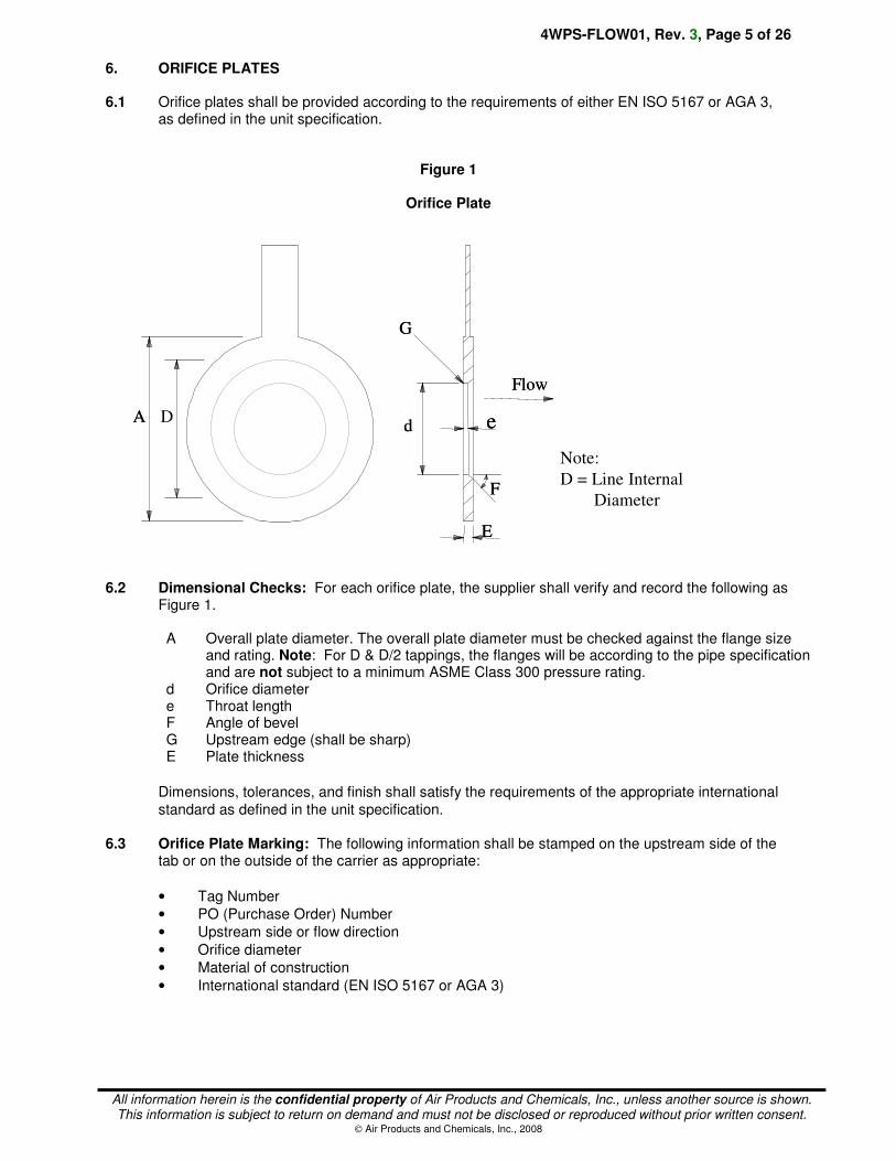
6. ORIFICE PLATES 6.1 Orifice plates shall be provided according to the requirements of either EN ISO 5167 or AGA 3,
as defined in the unit specification.
Figure 1
Orifice Plate
6.2 Dimensional Checks: For each orifice plate, the supplier shall verify and record the following as
Figure 1.
A Overall plate diameter. The overall plate diameter must be checked against the flange size and rating. Note: For D & D/2 tappings, the flanges will be according to the pipe specification and are not subject to a minimum ASME Class 300 pressure rating.
d Orifice diameter e Throat length F Angle of bevel G Upstream edge (shall be sharp) E Plate thickness
Dimensions, tolerances, and finish shall satisfy the requirements of the appropriate international
standard as defined in the unit specification.
6.3 Orifice Plate Marking: The following information shall be stamped on the upstream side of the
tab or on the outside of the carrier as appropriate:
• Tag Number
• PO (Purchase Order) Number
• Upstream side or flow direction
• Orifice diameter
• Material of construction
• International standard (EN ISO 5167 or AGA 3)
Ad e
Flow
E
F
G
Ad e
Flow
E
F
G
D
Note:
D = Line Internal
Diameter
4WPS-FLOW01, Rev. 3, Page 6 of 26
All information herein is the confidential property of Air Products and Chemicals, Inc., unless another source is shown. This information is subject to return on demand and must not be disclosed or reproduced without prior written consent.
Air Products and Chemicals, Inc., 2008
6.4 The following relaxation is permitted to the requirements of EN ISO 5167 unless otherwise specified in the unit specification:
• Dimension e in Figure 1 (orifice plates) shall not be less than 1 mm. This permits a deviation from the EN ISO 5167 requirement that 0.005D < e < 0.02D for line sizes < DN50 (NPS 2) to improve the wear characteristics of the plate.
7. ORIFICE FLANGES 7.1 Orifice flanges shall be provided according to ASME B16.36 unless otherwise stated in the unit
specification. 7.2 Orifice flanges shall be provided with weld neck flanges unless otherwise specified in the unit
specification. 7.3 Orifice flanges shall be provided complete with jacking bolts, studs, nuts, washers, and gaskets.
Studs, nuts, washers, and gaskets shall be provided according to the unit specification. 7.4 Unless otherwise specified, each orifice flange shall be provided with two 1/2" NPT threaded
pressure taps at 180 degrees. Each pressure tap hole shall be fitted with a pipe plug. 7.5 Where the unit specification specifies socket weld pressure taps, each flange shall be provided
with only one pressure tap. Socket weld size shall be DN15 (NPS 1/2) unless otherwise specified. 7.6 Orifice flanges shall be flange tapped or corner tapped as defined in the unit specification. 7.7 The supplier shall ensure that the taps are located appropriately for the specified gasket
compressed thickness. 7.8 Orifice flange internal diameter shall match the upstream pipework internal diameter (D) specified
in the unit specification.
4WPS-FLOW01, Rev. 3, Page 7 of 26
All information herein is the confidential property of Air Products and Chemicals, Inc., unless another source is shown. This information is subject to return on demand and must not be disclosed or reproduced without prior written consent.
Air Products and Chemicals, Inc., 2008
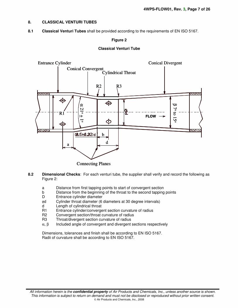
8. CLASSICAL VENTURI TUBES 8.1 Classical Venturi Tubes shall be provided according to the requirements of EN ISO 5167.
Figure 2
Classical Venturi Tube
8.2 Dimensional Checks: For each venturi tube, the supplier shall verify and record the following as
Figure 2:
a Distance from first tapping points to start of convergent section b Distance from the beginning of the throat to the second tapping points D Entrance cylinder diameter
φd Cylinder throat diameter (6 diameters at 30 degree intervals) d Length of cylindrical throat R1 Entrance cylinder/convergent section curvature of radius R2 Convergent section/throat curvature of radius R3 Throat/divergent section curvature of radius
α, β Included angle of convergent and divergent sections respectively Dimensions, tolerances and finish shall be according to EN ISO 5167. Radii of curvature shall be according to EN ISO 5167.
FLOW
Entrance Cylinder
Conical ConvergentCylindrical Throat
Conical Divergent
R2 R3
R1
a
b
d
Connecting Planes
α21
o+
1o
β7
oto
15
o
FLOW
Entrance Cylinder
Conical ConvergentCylindrical Throat
Conical Divergent
R2 R3
R1
a
b
d
Connecting Planes
α21
o+
1o
β7
oto
15
o
4WPS-FLOW01, Rev. 3, Page 8 of 26
All information herein is the confidential property of Air Products and Chemicals, Inc., unless another source is shown. This information is subject to return on demand and must not be disclosed or reproduced without prior written consent.
Air Products and Chemicals, Inc., 2008
8.3 Venturi Tube Marking: The following information shall be stamped on the outside of the venturi
tube:
• Tag Number
• PO (Purchase Order) Number
• Upstream side or flow direction
• Throat diameter and temperature of measurement
• Material of construction
• International Standard: EN ISO 5167
• Material/heat numbers traceable to ASTM and "Circuit Design Pressure" 8.4 Venturi Tube Method of Construction 8.4.1 The method of construction according to EN ISO 5167 will normally be defined in the unit
specification to be one of the following:
• "As cast" convergent section
• Machined convergent section
• Fabricated convergent section 8.4.2 Unless otherwise specified, classical venturi tubes shall be provided with four sets of 1/2" NPT
threaded pressure tappings as described in EN ISO 5167.

4WPS-FLOW01, Rev. 3, Page 9 of 26
All information herein is the confidential property of Air Products and Chemicals, Inc., unless another source is shown. This information is subject to return on demand and must not be disclosed or reproduced without prior written consent.
Air Products and Chemicals, Inc., 2008
9. LOW-LOSS INSERTION VENTURI TUBES 9.1 Low Loss Insertion Venturi Flow Tubes shall be provided according to the unit specification
and according to the requirements of this specification.
Figure 3
Typical Low Loss Insertion Venturi Flow Tube (Wafer Mounted between Flanges)
THROAT
DIAMETER
INLET CONE
THROAT
FLOW
OUTLET CONE
PROCESS PIPE
HOLDING
FLANGE
9.2 Dimensional Checks: For each insertion venturi tube, the supplier shall verify and record the
following as Figure 3:
• Cylinder throat diameter (6 diameters at 30 degree intervals)
• For elements mounted between flanges, dimensions for correct wafer mounting between the flange types specified in the unit specification
• Other dimensions, tolerances, and finish to satisfy the design requirements of the device.
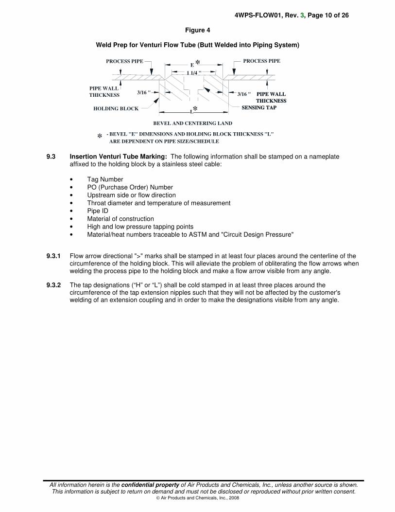
• Other design details (e.g., impact or non-impact upstream tapping design).
• For welded-in elements, weld preparation dimensions (illustrated in Figure 4). The weld prep requires a minimum 5 mm (3/16 in) "land" to provide sufficient guidance for the upstream and downstream piping so that concentric alignment of the flow tube is achieved without the need for backer rings.
Note: An impact design is as shown in Figure 3. A non-impact design has the upstream tapping fitted directly into the pipe upstream of the flow element.
4WPS-FLOW01, Rev. 3, Page 10 of 26
All information herein is the confidential property of Air Products and Chemicals, Inc., unless another source is shown. This information is subject to return on demand and must not be disclosed or reproduced without prior written consent.
Air Products and Chemicals, Inc., 2008
Figure 4
Weld Prep for Venturi Flow Tube (Butt Welded into Piping System)
PIPE WALL
1 1/4 "
E
SENSING TAPHOLDING BLOCK
*
*
PIPE WALL
THICKNESS
- BEVEL "E" DIMENSIONS AND HOLDING BLOCK THICKNESS "L"
ARE DEPENDENT ON PIPE SIZE/SCHEDULE
THICKNESS 3/16 "
PROCESS PIPE
SENSING TAP
BEVEL AND CENTERING LAND
PIPE WALL
THICKNESS
*
PROCESS PIPE
3/16 "
L
9.3 Insertion Venturi Tube Marking: The following information shall be stamped on a nameplate
affixed to the holding block by a stainless steel cable:
• Tag Number
• PO (Purchase Order) Number
• Upstream side or flow direction
• Throat diameter and temperature of measurement
• Pipe ID
• Material of construction
• High and low pressure tapping points
• Material/heat numbers traceable to ASTM and "Circuit Design Pressure"
9.3.1 Flow arrow directional ">" marks shall be stamped in at least four places around the centerline of the circumference of the holding block. This will alleviate the problem of obliterating the flow arrows when welding the process pipe to the holding block and make a flow arrow visible from any angle.
9.3.2 The tap designations (“H” or “L”) shall be cold stamped in at least three places around the circumference of the tap extension nipples such that they will not be affected by the customer's welding of an extension coupling and in order to make the designations visible from any angle.
4WPS-FLOW01, Rev. 3, Page 11 of 26
All information herein is the confidential property of Air Products and Chemicals, Inc., unless another source is shown. This information is subject to return on demand and must not be disclosed or reproduced without prior written consent.
Air Products and Chemicals, Inc., 2008
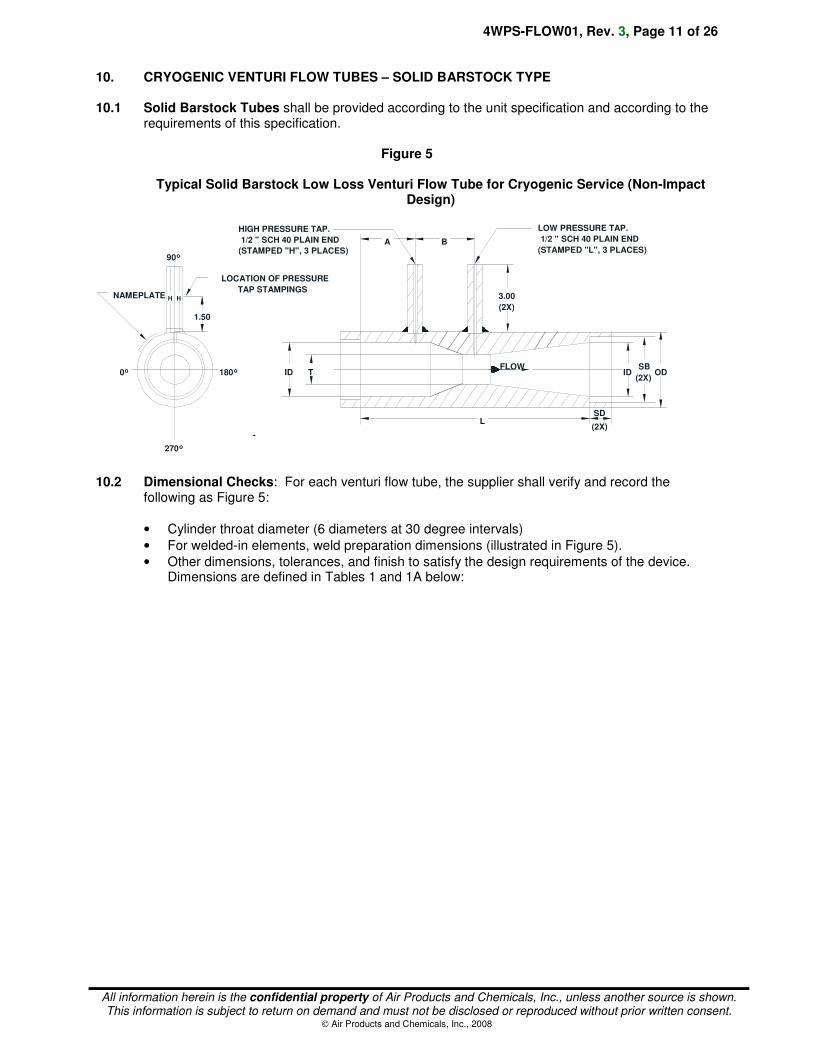
10. CRYOGENIC VENTURI FLOW TUBES – SOLID BARSTOCK TYPE 10.1 Solid Barstock Tubes shall be provided according to the unit specification and according to the
requirements of this specification.
Figure 5
Typical Solid Barstock Low Loss Venturi Flow Tube for Cryogenic Service (Non-Impact Design)
0o
90o
180o
270o
FLOW
L
ID ODSB
(2X)ID T
3.00
(2X)
A B
LOW PRESSURE TAP.
1/2 " SCH 40 PLAIN END
(STAMPED "L", 3 PLACES)
HIGH PRESSURE TAP.
1/2 " SCH 40 PLAIN END
(STAMPED "H", 3 PLACES)
NAMEPLATE
1.50
LOCATION OF PRESSURE
TAP STAMPINGSHH
-
SD
(2X)
10.2 Dimensional Checks: For each venturi flow tube, the supplier shall verify and record the
following as Figure 5:
• Cylinder throat diameter (6 diameters at 30 degree intervals)
• For welded-in elements, weld preparation dimensions (illustrated in Figure 5).
• Other dimensions, tolerances, and finish to satisfy the design requirements of the device. Dimensions are defined in Tables 1 and 1A below:
4WPS-FLOW01, Rev. 3, Page 12 of 26
All information herein is the confidential property of Air Products and Chemicals, Inc., unless another source is shown. This information is subject to return on demand and must not be disclosed or reproduced without prior written consent.
Air Products and Chemicals, Inc., 2008
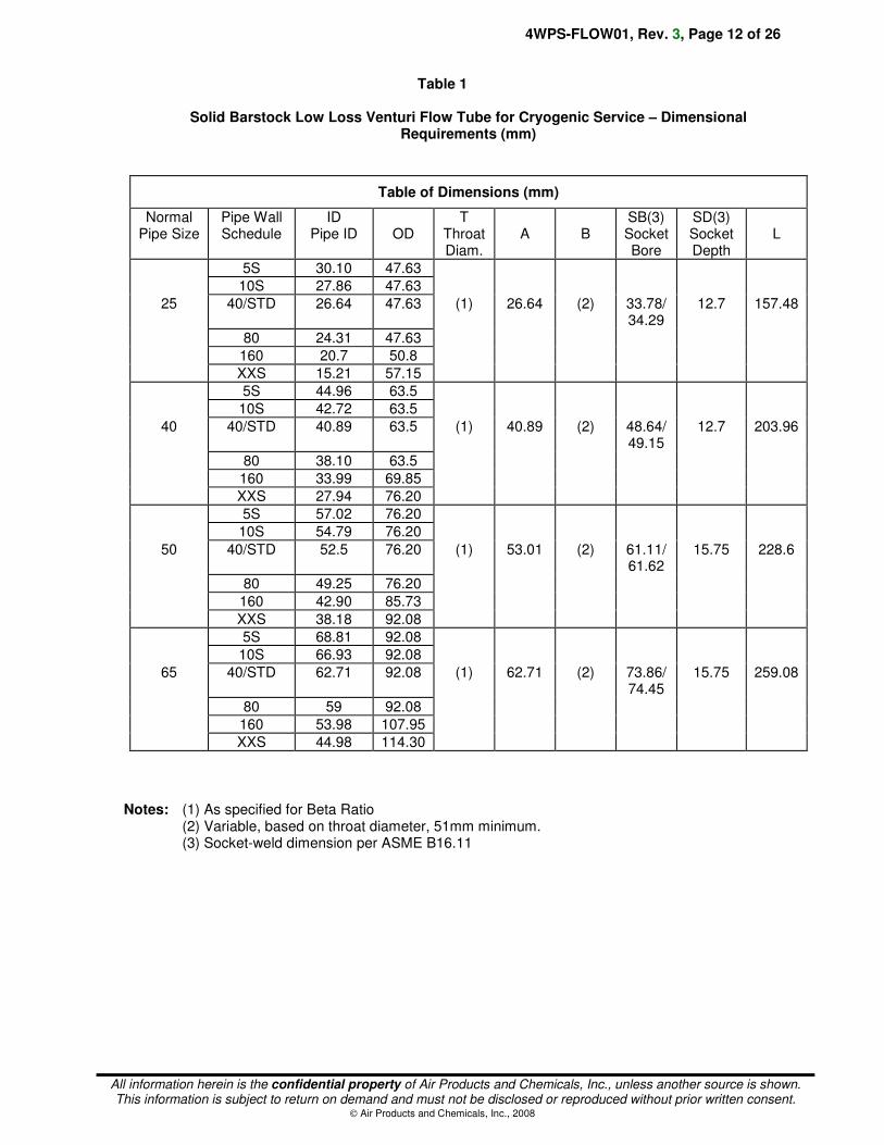
Table 1
Solid Barstock Low Loss Venturi Flow Tube for Cryogenic Service – Dimensional
Requirements (mm)
Table of Dimensions (mm)
Normal Pipe Size
Pipe Wall Schedule
ID Pipe ID
OD
T Throat Diam.
A
B
SB(3) Socket Bore
SD(3) Socket Depth
L
5S 30.10 47.63
10S 27.86 47.63
25 40/STD 26.64 47.63 (1) 26.64 (2) 33.78/ 34.29
12.7 157.48
80 24.31 47.63
160 20.7 50.8
XXS 15.21 57.15
5S 44.96 63.5
10S 42.72 63.5
40 40/STD 40.89 63.5 (1) 40.89 (2) 48.64/49.15
12.7 203.96
80 38.10 63.5
160 33.99 69.85
XXS 27.94 76.20
5S 57.02 76.20
10S 54.79 76.20
50 40/STD 52.5 76.20 (1) 53.01
(2) 61.11/61.62
15.75 228.6
80 49.25 76.20
160 42.90 85.73
XXS 38.18 92.08
5S 68.81 92.08
10S 66.93 92.08
65 40/STD 62.71 92.08 (1) 62.71
(2) 73.86/74.45
15.75 259.08
80 59 92.08
160 53.98 107.95
XXS 44.98 114.30
Notes: (1) As specified for Beta Ratio (2) Variable, based on throat diameter, 51mm minimum.
(3) Socket-weld dimension per ASME B16.11
4WPS-FLOW01, Rev. 3, Page 13 of 26
All information herein is the confidential property of Air Products and Chemicals, Inc., unless another source is shown. This information is subject to return on demand and must not be disclosed or reproduced without prior written consent.
Air Products and Chemicals, Inc., 2008
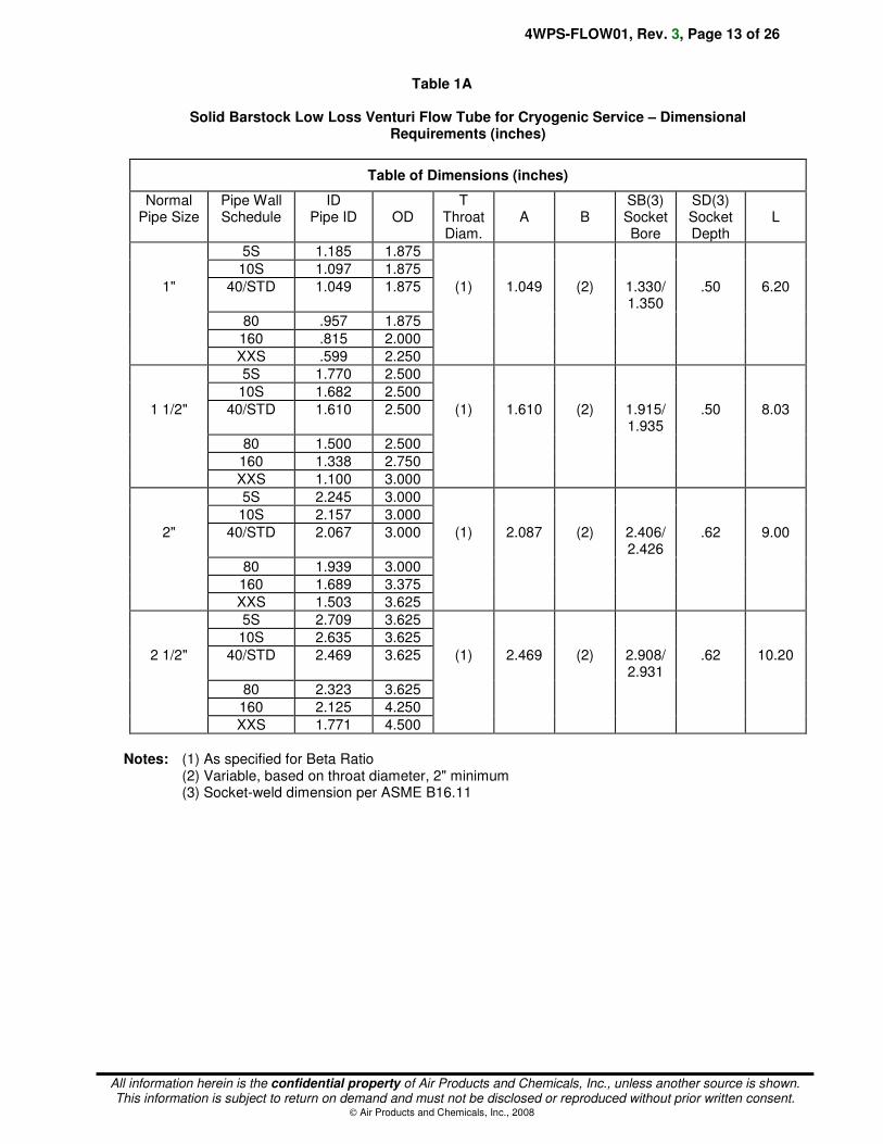
Table 1A
Solid Barstock Low Loss Venturi Flow Tube for Cryogenic Service – Dimensional
Requirements (inches)
Table of Dimensions (inches)
Normal Pipe Size
Pipe Wall Schedule
ID Pipe ID
OD
T Throat Diam.
A
B
SB(3) Socket Bore
SD(3) Socket Depth
L
5S 1.185 1.875
10S 1.097 1.875
1" 40/STD 1.049 1.875 (1) 1.049 (2) 1.330/1.350
.50 6.20
80 .957 1.875
160 .815 2.000
XXS .599 2.250
5S 1.770 2.500
10S 1.682 2.500
1 1/2" 40/STD 1.610 2.500 (1) 1.610 (2) 1.915/1.935
.50 8.03
80 1.500 2.500
160 1.338 2.750
XXS 1.100 3.000
5S 2.245 3.000
10S 2.157 3.000
2" 40/STD 2.067 3.000 (1) 2.087 (2) 2.406/2.426
.62 9.00
80 1.939 3.000
160 1.689 3.375
XXS 1.503 3.625
5S 2.709 3.625
10S 2.635 3.625
2 1/2" 40/STD 2.469 3.625 (1) 2.469 (2) 2.908/2.931
.62 10.20
80 2.323 3.625
160 2.125 4.250
XXS 1.771 4.500
Notes: (1) As specified for Beta Ratio (2) Variable, based on throat diameter, 2" minimum (3) Socket-weld dimension per ASME B16.11
4WPS-FLOW01, Rev. 3, Page 14 of 26
All information herein is the confidential property of Air Products and Chemicals, Inc., unless another source is shown. This information is subject to return on demand and must not be disclosed or reproduced without prior written consent.
Air Products and Chemicals, Inc., 2008
10.3 Barstock Venturi Tube Marking: The following information shall be stamped on the outside of
the Venturi Tube:
• Tag Number
• PO (Purchase Order) Number
• Upstream side or flow direction
• Throat diameter and temperature of measurement
• Pipe ID
• Material of construction
• High and low pressure tapping points
• Material/heat numbers traceable to ASTM and "Circuit Design Pressure"
10.3.1 The tap designations (“H” or “L”) shall be cold stamped in at least three places around the circumference of the tap extension nipples such that they will not be affected by the customer's welding of an extension coupling and in order to make the designations visible from any angle.
4WPS-FLOW01, Rev. 3, Page 15 of 26
All information herein is the confidential property of Air Products and Chemicals, Inc., unless another source is shown. This information is subject to return on demand and must not be disclosed or reproduced without prior written consent.
Air Products and Chemicals, Inc., 2008
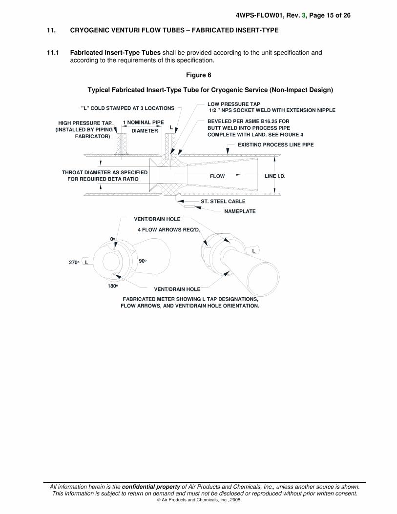
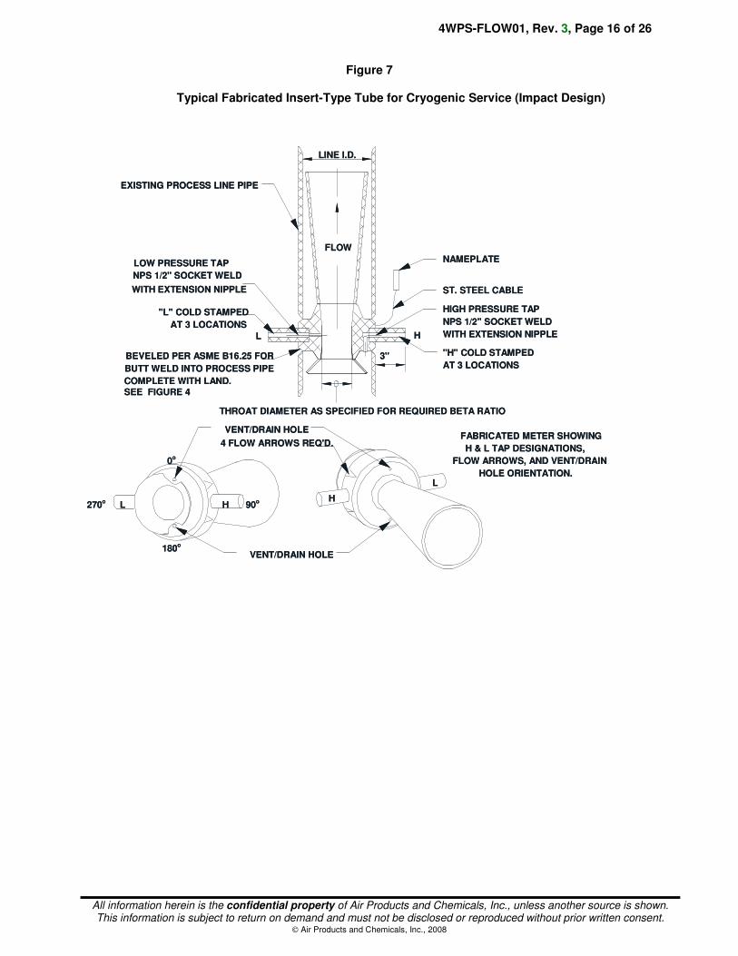
11. CRYOGENIC VENTURI FLOW TUBES – FABRICATED INSERT-TYPE
11.1 Fabricated Insert-Type Tubes shall be provided according to the unit specification and according to the requirements of this specification.
Figure 6
Typical Fabricated Insert-Type Tube for Cryogenic Service (Non-Impact Design)
LINE I.D.
EXISTING PROCESS LINE PIPE
"L" COLD STAMPED AT 3 LOCATIONSLOW PRESSURE TAP 1/2 " NPS SOCKET WELD WITH EXTENSION NIPPLE
BEVELED PER ASME B16.25 FOR
BUTT WELD INTO PROCESS PIPE
COMPLETE WITH LAND. SEE FIGURE 4
ST. STEEL CABLE
NAMEPLATE
FLOW
4 FLOW ARROWS REQ'D.
L
L
THROAT DIAMETER AS SPECIFIED
FOR REQUIRED BETA RATIO
0o
90o
180o
270o
HIGH PRESSURE TAP
(INSTALLED BY PIPING
FABRICATOR)
VENT/DRAIN HOLE
VENT/DRAIN HOLE
FABRICATED METER SHOWING L TAP DESIGNATIONS,
FLOW ARROWS, AND VENT/DRAIN HOLE ORIENTATION.
1 NOMINAL PIPE
DIAMETERL
4WPS-FLOW01, Rev. 3, Page 16 of 26
All information herein is the confidential property of Air Products and Chemicals, Inc., unless another source is shown. This information is subject to return on demand and must not be disclosed or reproduced without prior written consent.
Air Products and Chemicals, Inc., 2008
Figure 7
Typical Fabricated Insert-Type Tube for Cryogenic Service (Impact Design)
LINE I.D.
L
EXISTING PROCESS LINE PIPE
BEVELED PER ASME B16.25 FOR
BUTT WELD INTO PROCESS PIPE
COMPLETE WITH LAND. SEE FIGURE 4
3"
H
ST. STEEL CABLE
NAMEPLATE
FLOW
4 FLOW ARROWS REQ'D.
HHL
L
"H" COLD STAMPED
AT 3 LOCATIONS
LOW PRESSURE TAP
NPS 1/2" SOCKET WELD
"L" COLD STAMPED
AT 3 LOCATIONS
HIGH PRESSURE TAP
NPS 1/2" SOCKET WELD
WITH EXTENSION NIPPLE
0o
180o
270o
90o
VENT/DRAIN HOLE
VENT/DRAIN HOLE
THROAT DIAMETER AS SPECIFIED FOR REQUIRED BETA RATIO
FABRICATED METER SHOWING
H & L TAP DESIGNATIONS,
FLOW ARROWS, AND VENT/DRAIN
HOLE ORIENTATION.
WITH EXTENSION NIPPLE
4WPS-FLOW01, Rev. 3, Page 17 of 26
All information herein is the confidential property of Air Products and Chemicals, Inc., unless another source is shown. This information is subject to return on demand and must not be disclosed or reproduced without prior written consent.
Air Products and Chemicals, Inc., 2008
11.2 Dimensional Checks: For each venturi flow tube, the supplier shall verify and record the following as Figures 6 and 7:
• Cylinder throat diameter (6 diameters at 30 degree intervals).
• Weld preparation dimensions (illustrated in Figure 4). The weld preparation requires a minimum 5 mm (3/16 in) "land" to provide sufficient guidance for the upstream and downstream piping so that concentric alignment of the flow tube is achieved without the need for backer rings.
• Other dimensions, tolerances, and finish to satisfy the design requirements of the device. Dimensions are defined in Tables 2 and 2A below:
4WPS-FLOW01, Rev. 3, Page 18 of 26
All information herein is the confidential property of Air Products and Chemicals, Inc., unless another source is shown. This information is subject to return on demand and must not be disclosed or reproduced without prior written consent.
Air Products and Chemicals, Inc., 2008
Table 2
Fabricated Meter Holding-Block Dimensions per Line Size and Schedule (mm)
Line Size (mm)
Schedule
Wall Thickness (mm)
Bevel (mm)
Dim "E" (mm)
Dim "L" (mm)
80 5S 2.11 0.41 35.74 42.16
10S 3.05 2.34 39.6 49.02
40 (Std.) 5.49 4.22 43.33 52.83
80 7.62 5.84 46.61 56.13
160 11.13 8.53 51.99 61.47
XXS 15.24 11.68 58.32 67.82
100 5S 2.11 1.63 38.15 47.75
10S 3.05 2.34 39.6 49.02
40 (Std.) 6.02 4.62 44.17 53.59
80 8.56 6.58 48.06 57.66
120 11.13 8.53 51.99 61.47
160 13.49 10.34 55.63 65.02
XXS 17.12 13.13 61.19 70.61
150 5S 2.77 2.13 39.17 48.77
10S 3.4 2.62 40.16 49.78
40 (Std.) 7.11 5.46 45.85 55.37
80 10.97 8.41 51.77 61.21
120 14.27 10.95 56.82 66.29
160 18.26 14.02 62.94 72.39
XXS 21.95 16.84 68.61 78.23
200 5S 2.77 2.13 39.17 48.77
10S 3.76 2.9 40.69 50.29
20 6.35 4.88 44.68 54.1
30 7.04 5.41 45.72 55.37
40 (Std.) 8.18 6.27 47.47 56.9
60 10.31 7.92 50.75 60.2
80 (XS) 12.7 9.75 54.41 64.01
100 15.09 11.58 58.09 67.56
120 18.26 14.02 62.94 72.39
140 20.62 15.82 66.57 76.2
XXS 22.23 17.04 69.04 78.49
160 23.01 17.65 70.23 79.76
250 5S 3.4 2.62 40.16 49.78
10S 4.19 3.23 41.35 50.8
20 6.35 4.88 44.68 54.1
30 7.8 5.99 46.89 56.39
40 (Std.) 9.27 7.11 49.15 58.67
60 (XS) 12.7 9.75 54.41 64.01
80 15.09 11.58 58.09 67.56
100 18.26 14.02 62.94 72.39
120 21.44 16.46 67.82 77.47
140 25.4 19.48 73.91 83.31
160 28.58 21.92 78.77 88.39
4WPS-FLOW01, Rev. 3, Page 19 of 26
All information herein is the confidential property of Air Products and Chemicals, Inc., unless another source is shown. This information is subject to return on demand and must not be disclosed or reproduced without prior written consent.
Air Products and Chemicals, Inc., 2008
Table 2 (continued)
Fabricated Meter Holding-Block Dimensions per Line Size and Schedule (mm)
Line Size (mm)
Schedule
Wall Thickness (mm)
Bevel (mm)
Dim "E" (mm)
Dim "L" (mm)
300 5S 3.96 3.05 41 50.55
10S 4.57 3.51 41.94 51.56
20 6.35 4.88 44.68 54.1
30 8.38 6.43 47.78 57.4
STD. 9.53 7.32 49.53 59.18
40 10.31 7.92 50.75 60.2
XS 12.7 9.75 54.41 64.01
60 14.27 10.95 56.82 66.29
80 17.48 13.41 61.75 71.37
100 21.44 16.46 67.82 77.47
120 25.4 19.48 73.91 83.31
140 28.58 21.92 78.77 88.39
160 33.32 25.58 86.06 95.5
350 5S 3.96 3.05 41 50.55
10S 4.78 3.66 42.27 51.82
10 6.35 4.88 44.68 54.1
20 7.92 6.07 47.09 56.64
30 (Std.) 9.53 7.32 49.53 59.18
40 11.13 8.53 51.99 61.47
XS 12.7 9.75 54.41 64.01
60 15.09 11.58 58.09 67.56
80 19.05 14.61 64.16 73.66
100 23.83 18.29 71.5 81.03
120 27.79 21.31 77.57 87.12
140 31.75 24.36 83.64 93.22
160 35.71 27.41 89.74 99.31
400 5S 4.19 3.23 41.35 50.8
10S 4.78 3.66 42.27 51.82
10 6.35 4.88 44.68 54.1
20 7.92 6.07 47.09 56.64
30 (Std.) 9.53 7.32 49.53 59.18
40 (XS) 12.7 9.75 54.41 64.01
60 16.66 12.78 60.5 70.1
80 21.44 16.46 67.82 77.47
100 26.19 20.09 75.11 84.58
120 30.96 23.75 82.45 91.95
140 36.53 28.02 90.98 100.58
160 40.49 31.06 97.05 106.68
450 5S 4.19 3.23 41.35 50.8
10S 4.78 3.66 42.27 51.82
10 6.35 4.88 44.68 54.1
20 7.92 6.07 47.09 56.64
STD. 9.53 7.32 49.53 59.18
4WPS-FLOW01, Rev. 3, Page 20 of 26
All information herein is the confidential property of Air Products and Chemicals, Inc., unless another source is shown. This information is subject to return on demand and must not be disclosed or reproduced without prior written consent.
Air Products and Chemicals, Inc., 2008
Table 2 (continued)
Fabricated Meter Holding-Block Dimensions per Line Size and Schedule (mm)
Line Size (mm)
Schedule
Wall Thickness (mm)
Bevel (mm)
Dim "E" (mm)
Dim "L" (mm)
30 11.13 8.53 51.99 61.47
XS 12.7 9.75 54.41 64.01
40 14.27 10.95 56.82 66.29
60 19.05 14.61 64.16 73.66
80 23.83 18.29 71.5 81.03
100 29.36 22.53 79.98 89.41
120 34.93 26.8 88.52 98.04
140 39.67 30.45 95.81 105.41
160 45.24 34.72 104.34 113.79
500 5S 4.78 3.66 42.27 51.82
10S 5.54 4.24 43.43 52.83
10 6.35 4.88 44.68 54.1
20 (Std.) 9.53 7.32 49.53 59.18
30 (XS) 12.7 9.75 54.41 64.01
40 15.09 11.58 58.09 67.56
60 20.62 15.82 66.57 76.2
80 26.19 20.09 75.11 84.58
100 32.54 24.97 84.86 94.49
120 38.1 29.24 93.4 102.87
140 44.45 34.11 103.15 112.78
160 50.01 38.38 111.68 121.16
600 5S 5.54 4.24 43.43 52.83
10 6.35 4.88 44.68 54.1
20 (Std.) 9.53 7.32 49.53 59.18
XS 12.7 9.75 54.41 64.01
30 14.27 10.95 56.82 66.29
40 17.48 13.41 61.75 71.37
60 24.61 18.9 72.69 82.3
80 30.96 23.75 82.45 91.95
100 38.89 29.85 94.62 104.14
120 46.02 35.31 105.56 115.06
140 52.37 40.18 115.29 124.71
160 59.54 45.69 126.29 135.89
Above 600 mm, consult manufacturer
4WPS-FLOW01, Rev. 3, Page 21 of 26
All information herein is the confidential property of Air Products and Chemicals, Inc., unless another source is shown. This information is subject to return on demand and must not be disclosed or reproduced without prior written consent.
Air Products and Chemicals, Inc., 2008
Table 2A
Fabricated Meter Holding-Block Dimensions per Line Size and Schedule (inches)
Line Size (inches)
Schedule
Wall Thickness (inches)
Bevel (inches)
Dim "E" (inches)
Dim "L" (inches)
3 5S 0.083 0.016 1.407 1.66
10S 0.120 0.092 1.559 1.93
40 (Std.) 0.216 0.166 1.706 2.08
80 0.300 0.230 1.835 2.21
160 0.438 0.336 2.047 2.42
XXS 0.600 0.460 2.296 2.67
4 5S 0.083 0.064 1.502 1.88
10S 0.120 0.092 1.559 1.93
40 (Std.) 0.237 0.182 1.739 2.11
80 0.337 0.259 1.892 2.27
120 0.438 0.336 2.047 2.42
160 0.531 0.407 2.190 2.56
XXS 0.674 0.517 2.409 2.78
6 5S 0.109 0.084 1.542 1.92
10S 0.134 0.103 1.581 1.96
40 (Std.) 0.280 0.215 1.805 2.18
80 0.432 0.331 2.038 2.41
120 0.562 0.431 2.237 2.61
160 0.719 0.552 2.478 2.85
XXS 0.864 0.663 2.701 3.08
8 5S 0.109 0.084 1.542 1.92
10S 0.148 0.114 1.602 1.98
20 0.250 0.192 1.759 2.13
30 0.277 0.213 1.800 2.18
40 (Std.) 0.322 0.247 1.869 2.24
60 0.406 0.312 1.998 2.37
80 (XS) 0.500 0.384 2.142 2.52
100 0.594 0.456 2.287 2.66
120 0.719 0.552 2.478 2.85
140 0.812 0.623 2.621 3.00
XXS 0.875 0.671 2.718 3.09
160 0.906 0.695 2.765 3.14
10 5S 0.134 0.103 1.581 1.96
10S 0.165 0.127 1.628 2.00
20 0.250 0.192 1.759 2.13
30 0.307 0.236 1.846 2.22
40 (Std.) 0.365 0.280 1.935 2.31
60 (XS) 0.500 0.384 2.142 2.52
80 0.594 0.456 2.287 2.66
100 0.719 0.552 2.478 2.85
120 0.844 0.648 2.670 3.05
140 1.000 0.767 2.910 3.28
160 1.125 0.863 3.101 3.48
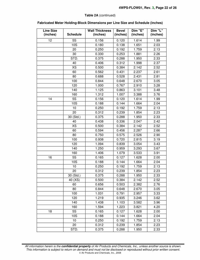
4WPS-FLOW01, Rev. 3, Page 22 of 26
All information herein is the confidential property of Air Products and Chemicals, Inc., unless another source is shown. This information is subject to return on demand and must not be disclosed or reproduced without prior written consent.
Air Products and Chemicals, Inc., 2008
Table 2A (continued)
Fabricated Meter Holding-Block Dimensions per Line Size and Schedule (inches)
Line Size (inches)
Schedule
Wall Thickness (inches)
Bevel (inches)
Dim "E" (inches)
Dim "L" (inches)
12 5S 0.156 0.120 1.614 1.99
10S 0.180 0.138 1.651 2.03
20 0.250 0.192 1.759 2.13
30 0.330 0.253 1.881 2.26
STD. 0.375 0.288 1.950 2.33
40 0.406 0.312 1.998 2.37
XS 0.500 0.384 2.142 2.52
60 0.562 0.431 2.237 2.61
80 0.688 0.528 2.431 2.81
100 0.844 0.648 2.670 3.05
120 1.000 0.767 2.910 3.28
140 1.125 0.863 3.101 3.48
160 1.312 1.007 3.388 3.76
14 5S 0.156 0.120 1.614 1.99
10S 0.188 0.144 1.664 2.04
10 0.250 0.192 1.759 2.13
20 0.312 0.239 1.854 2.23
30 (Std.) 0.375 0.288 1.950 2.33
40 0.438 0.336 2.047 2.42
XS 0.500 0.384 2.142 2.52
60 0.594 0.456 2.287 2.66
80 0.750 0.575 2.526 2.90
100 0.938 0.720 2.815 3.19
120 1.094 0.839 3.054 3.43
140 1.250 0.959 3.293 3.67
160 1.406 1.079 3.533 3.91
16 5S 0.165 0.127 1.628 2.00
10S 0.188 0.144 1.664 2.04
10 0.250 0.192 1.759 2.13
20 0.312 0.239 1.854 2.23
30 (Std.) 0.375 0.288 1.950 2.33
40 (XS) 0.500 0.384 2.142 2.52
60 0.656 0.503 2.382 2.76
80 0.844 0.648 2.670 3.05
100 1.031 0.791 2.957 3.33
120 1.219 0.935 3.246 3.62
140 1.438 1.103 3.582 3.96
160 1.594 1.223 3.821 4.20
18 5S 0.165 0.127 1.628 2.00
10S 0.188 0.144 1.664 2.04
10 0.250 0.192 1.759 2.13
20 0.312 0.239 1.854 2.23
STD. 0.375 0.288 1.950 2.33
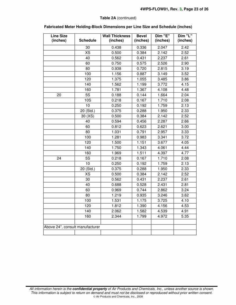
4WPS-FLOW01, Rev. 3, Page 23 of 26
All information herein is the confidential property of Air Products and Chemicals, Inc., unless another source is shown. This information is subject to return on demand and must not be disclosed or reproduced without prior written consent.
Air Products and Chemicals, Inc., 2008
Table 2A (continued)
Fabricated Meter Holding-Block Dimensions per Line Size and Schedule (inches)
Line Size (inches)
Schedule
Wall Thickness (inches)
Bevel (inches)
Dim "E" (inches)
Dim "L" (inches)
30 0.438 0.336 2.047 2.42
XS 0.500 0.384 2.142 2.52
40 0.562 0.431 2.237 2.61
60 0.750 0.575 2.526 2.90
80 0.938 0.720 2.815 3.19
100 1.156 0.887 3.149 3.52
120 1.375 1.055 3.485 3.86
140 1.562 1.199 3.772 4.15
160 1.781 1.367 4.108 4.48
20 5S 0.188 0.144 1.664 2.04
10S 0.218 0.167 1.710 2.08
10 0.250 0.192 1.759 2.13
20 (Std.) 0.375 0.288 1.950 2.33
30 (XS) 0.500 0.384 2.142 2.52
40 0.594 0.456 2.287 2.66
60 0.812 0.623 2.621 3.00
80 1.031 0.791 2.957 3.33
100 1.281 0.983 3.341 3.72
120 1.500 1.151 3.677 4.05
140 1.750 1.343 4.061 4.44
160 1.969 1.511 4.397 4.77
24 5S 0.218 0.167 1.710 2.08
10 0.250 0.192 1.759 2.13
20 (Std.) 0.375 0.288 1.950 2.33
XS 0.500 0.384 2.142 2.52
30 0.562 0.431 2.237 2.61
40 0.688 0.528 2.431 2.81
60 0.969 0.744 2.862 3.24
80 1.219 0.935 3.246 3.62
100 1.531 1.175 3.725 4.10
120 1.812 1.390 4.156 4.53
140 2.062 1.582 4.539 4.91
160 2.344 1.799 4.972 5.35
Above 24", consult manufacturer
4WPS-FLOW01, Rev. 3, Page 24 of 26
All information herein is the confidential property of Air Products and Chemicals, Inc., unless another source is shown. This information is subject to return on demand and must not be disclosed or reproduced without prior written consent.
Air Products and Chemicals, Inc., 2008
11.3 Insertion Venturi Tube Marking: The following information shall be stamped on a nameplate
affixed to the holding block by a stainless steel cable:
• Tag Number
• PO (Purchase Order) Number
• Flow direction arrows
• Throat diameter and temperature of measurement
• Pipe ID
• Material of construction
• High and low pressure tapping points
• Material/heat numbers traceable to ASTM and "Circuit Design Pressure"
11.3.1 Flow arrow directional “>” marks shall be stamped in at least four places around the centerline of the circumference of the holding block. This will alleviate the problem of obliterating the flow arrows when welding the process pipe to the holding block and make a flow arrow visible from any angle.
11.3.2 The tap designations (“H” or “L”) shall be cold stamped in at least three places around the circumference of the tap extension nipples such that they will not be affected by the customer's welding of an extension coupling and in order to make the designations visible from any angle.
4WPS-FLOW01, Rev. 3, Page 25 of 26
All information herein is the confidential property of Air Products and Chemicals, Inc., unless another source is shown. This information is subject to return on demand and must not be disclosed or reproduced without prior written consent.
Air Products and Chemicals, Inc., 2008
12. AVERAGING PITOT TUBES
12.1 Ancillary Equipment: Averaging pitot tubes shall be provided complete with all necessary components for installation in a process line by others. Equipment shall include the following:
• Mounting kit necessary to mount, seal, and support the tube in the process line.
• Opposite wall support (if required for the combination of tube and process conditions, to be determined by the supplier).
• Isolation valves. 12.2 Design Conditions: The averaging pitot tube, together with all direct-mounted ancillary
equipment (including valves) shall be suitable for the full range of design conditions specified on the unit specification.
12.3 Averaging Pitot Tube Options: The following optional/additional requirements are required only
when specified in the unit specification: 12.3.1 High Performance Averaging Pitot Tube is a tube with the following design features:
• Averaging of both high and low pressure measurements by multi-pressure ports.
• Increased accuracy beyond that offered by a simple circular cross sectional averaging pitot tube. Empirical test data from independent laboratories shall be available to support claims of increased accuracy.
12.3.2 Flanged Model: A flanged averaging pitot, together with flanged mounting kit. 12.3.3 Integral Temperature Element: A temperature element installed inside the averaging pitot tube to
enable temperature compensation of gas flow without needing a separate tapping point. 12.3.4 Integral Manifold Head for Direct Transmitter Mounting permits the direct flange mounting of a
differential pressure transmitter (e.g., with 54 mm centers).
4WPS-FLOW01, Rev. 3, Page 26 of 26
All information herein is the confidential property of Air Products and Chemicals, Inc., unless another source is shown. This information is subject to return on demand and must not be disclosed or reproduced without prior written consent.
Air Products and Chemicals, Inc., 2008
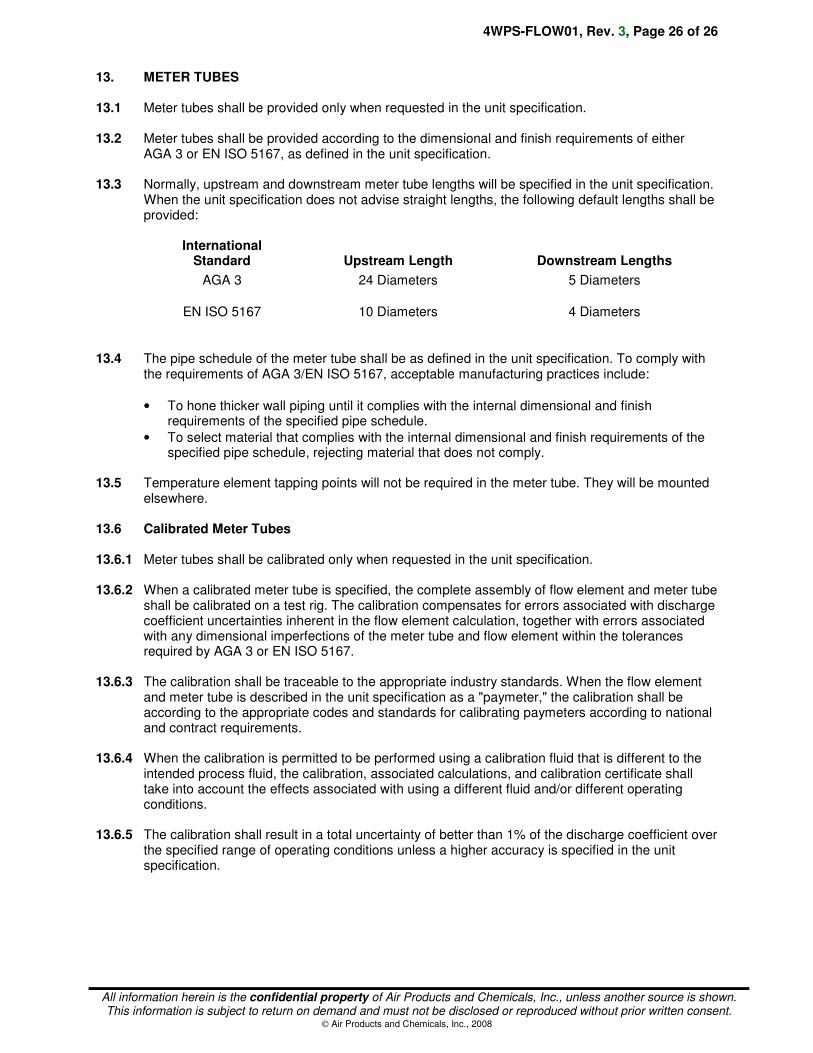
13. METER TUBES 13.1 Meter tubes shall be provided only when requested in the unit specification. 13.2 Meter tubes shall be provided according to the dimensional and finish requirements of either
AGA 3 or EN ISO 5167, as defined in the unit specification. 13.3 Normally, upstream and downstream meter tube lengths will be specified in the unit specification.
When the unit specification does not advise straight lengths, the following default lengths shall be provided:
International
Standard
Upstream Length
Downstream Lengths
AGA 3 24 Diameters 5 Diameters
EN ISO 5167 10 Diameters 4 Diameters
13.4 The pipe schedule of the meter tube shall be as defined in the unit specification. To comply with
the requirements of AGA 3/EN ISO 5167, acceptable manufacturing practices include:
• To hone thicker wall piping until it complies with the internal dimensional and finish requirements of the specified pipe schedule.
• To select material that complies with the internal dimensional and finish requirements of the specified pipe schedule, rejecting material that does not comply.
13.5 Temperature element tapping points will not be required in the meter tube. They will be mounted
elsewhere. 13.6 Calibrated Meter Tubes 13.6.1 Meter tubes shall be calibrated only when requested in the unit specification. 13.6.2 When a calibrated meter tube is specified, the complete assembly of flow element and meter tube
shall be calibrated on a test rig. The calibration compensates for errors associated with discharge coefficient uncertainties inherent in the flow element calculation, together with errors associated with any dimensional imperfections of the meter tube and flow element within the tolerances required by AGA 3 or EN ISO 5167.
13.6.3 The calibration shall be traceable to the appropriate industry standards. When the flow element
and meter tube is described in the unit specification as a "paymeter," the calibration shall be according to the appropriate codes and standards for calibrating paymeters according to national and contract requirements.
13.6.4 When the calibration is permitted to be performed using a calibration fluid that is different to the
intended process fluid, the calibration, associated calculations, and calibration certificate shall take into account the effects associated with using a different fluid and/or different operating conditions.
13.6.5 The calibration shall result in a total uncertainty of better than 1% of the discharge coefficient over
the specified range of operating conditions unless a higher accuracy is specified in the unit specification.