flow and transport in porous media - iit kanpur mechanics... · 2014-02-04 · flow and transport...
TRANSCRIPT

FLOW AND TRANSPORT IN POROUS MEDIAFLOW AND TRANSPORT IN POROUS MEDIA WITH APPLICATIONS
K. MuralidharDepartment of Mechanical EngineeringIndian Institute of Technology Kanpur
Kanpur 208016 India
TEQIP W k h A li d M h iTEQIP Workshop on Applied Mechanics 5‐7 October 2013, IIT Kanpur

Flow through gravel sand soilFlow through gravel, sand, soil
Earliest forms of porousEarliest forms of porous media studied in the literature{Ground water flow; Water{Ground water flow; Water resources engineering}

ComplexityComplexity
o Flow path tortuouspo Geometry is three dimensional and not clearly
definedo Original approaches seek to relate pressure drop
and flow rate, adopting a volume‐averaged perspective
o It has led to local volume‐averaging (REV)o Averaging results in new model parameters

Representative elementary volume (REV)Representative elementary volume (REV)
Solid phase rigid and fixedClosely packed arrangement REV is larger than the pore volumevolume
Look for solutions at a scale much larger than the REVmuch larger than the REV
Porous continuumPorous continuum

Pore scale REV laboratory scale field scalePore scale, REV, laboratory scale, field scale
Pore scale and particle diameter 1 10 micronsdiameter 1‐10 microns
REV 0.1‐1 mmLaboratory scale 50‐200 mmyField scale 1 m – 1 km – 1000
km

What constitutes a porous medium?pSystems of interest could be naturally porous
reservoirengineers.com

Alternatively
they could be modeledmodeled as one under certain conditions.
rack of a HPC systemrack of a HPC system
Miniature pulse
Metal foam used as a heat sinktube cryocooler

TerminologyTerminology
V l d l it t tVolume averaged velocity, temperatureFluid pressureSaturationMass fractions
Improved models: Phase velocity and temperatureImproved models: Phase velocity and temperature
Parameters arising from averagingP itPorosityPermeabilityRelative permeabilityp y
(i) Transported variables and (ii) model parameters
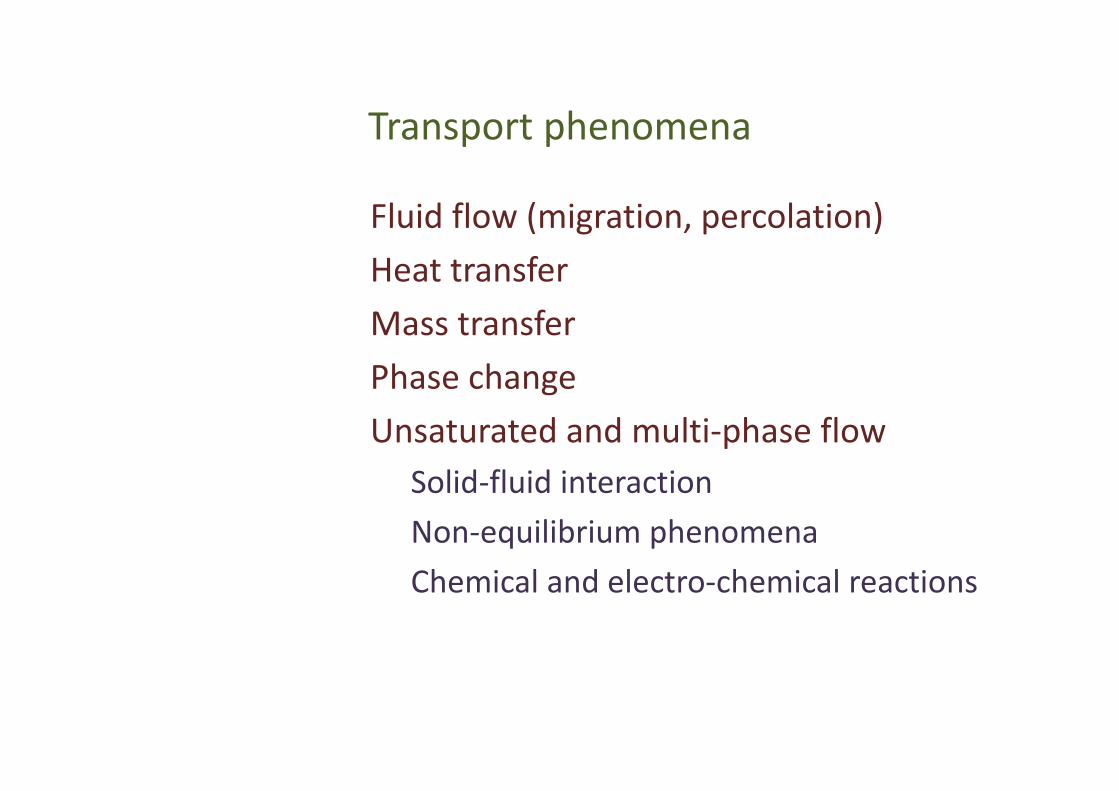
Transport phenomenaTransport phenomena
Fluid flow (migration percolation)Fluid flow (migration, percolation)Heat transferMass transferPhase changeUnsaturated and multi‐phase flow
Solid‐fluid interactionSolid‐fluid interactionNon‐equilibrium phenomenaCh i l d l t h i l tiChemical and electro‐chemical reactions

First principles approachFirst principles approach
o Flow of water in the pores of a matrix will satisfy Navier‐Stokes equations.
o When Red is small (< 1), Stokes equations are applicable.
o Solving these equations in a three dimensional complex geometry is unthinkableunthinkable.co p e geo e y s u ab eu ab e
o When other mechanisms of transport are present a first‐principles approach is ruled outruled outpresent, a first‐principles approach is ruled outruled out.

Historical perspectiveHistorical perspective
D ’ l (h i t iDarcy’s law (homogeneous, isotropic porous region, small Reynolds number)
1 Re
pudpKu
Fewer variables complex geometry is now
Fewer variables, complex geometry is now mapped to several variables in a simple geometrygeometry
Porous continuum

Mathematical modelingMathematical modeling
1Re pud
pKuDarcy’s law
with gravity
1 Re
pu
)( gzpKu
Incompressible medium0 u
02 p
steady and unsteady
Compressible medium
0 u
p
ut
2
0
Compressible fluid
ptpS 2
0 ( ) linearu p
(gas/liquid)2
2 2 2
0 ( ) linear
p
u ptp pp p
2 2 0 (steady)
pp pt t
p

Material propertiesMaterial properties
and are fluid properties – density and viscosity.
The solid phase defines the pore space.
Pore space does not change during flow; if at all, it changes in a prescribed manner.

Model parametersModel parameters
3 2d 22 scales with (pore diameter)
180(1 )[ ] [ ] 0 (extended Darcy's law)
pdK
Ku p K p
2
[ ] 0 (extended Darcy s law)
power consumed ( )
u p K p
K p
or power dissipated
Permeability, in general is a second order tensor.Darcy’s law can be derived from Stokes equations (low Reynolds number).Factor 180 in the expression for K is uncertain; a range 150‐180 is preferred.Experiments are carried out with random close packing random close packing arrangement.Fluid saturates the pore space.Particle diameter is constant over the region of interest.Wall effects secondary.

Boundary conditionsBoundary conditions
No mass flux through the solid wallsNo‐slip condition cannot be appliedBeavers‐Joseph condition at fluid‐porous region interfaceinterface
( )f B Jf P M
uu u
y K

AnalysisAnalysis
Note similarity between heat conduction and porous medium equations. Hencepressure – temperaturevelocity (flow) – heat flux (heat transfer)permeability thermal conductivitypermeability – thermal conductivity Both processes are irreversible and
are entropy generation rates2 2( ) ( )k T K p py g
Text books on flow through porous media look remarkably like
( ) ( )k p
Text books on flow through porous media look remarkably like books on diffusive heat and mass transfer.

Sample solutionsp

Extended Darcy’s lawExtended Darcy s law
' 2Brinkman 0 ( ' ; low Reynolds number)
Bulk acceleration
p u uK
2'( )
Body force field (all Reynolds numbers)
du u u u p u udt t K
Body force field (all Reynolds numbers)
(viscous + foru u fu uK K
m drag)
5 0.51.8 1Forschheimer constant
(180 )Brinkman Forschheimer corrected momentum equation
fK
2
Brinkman-Forschheimer corrected momentum equation'( )du u u u p u fu u u
dt t K

Non Darcy flow in a Porous MediumNon‐Darcy flow in a Porous Medium
mass 0
momentum ( )
udu u u u
2
momentum ( )
'
u udt t
p u fu u uK
K
Resembles Navier‐Stokes equations;Approximate and numerical tools can be used;
Transition points can be located;T b l t fl i di b t di dTurbulent flow in porous media can be studied;
Compressible flow equations can be set‐up.
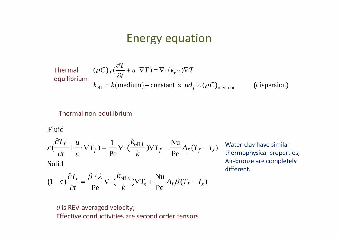
Energy equationEnergy equation
Teff
eff medium
( ) ( ) ( )
(medium) constant ( ) (dispersion)
f
p
TC u T k Tt
k k ud C
Thermal equilibrium
Thermal non‐equilibrium
eff,f
Fluid
1 Nu( ) ( ) ( )fT ku T T A T T
Water‐clay have similar ,( ) ( ) ( )Pe Pe
Solid/ N
ff f f f sT T A T T
t k
kT
Water clay have similarthermophysical properties;Air‐bronze are completelydifferent.
eff,s/ Nu(1 ) ( ) ( )Pe Pe
ss f f s
kT T A T Tt k
u is REV‐averaged velocity; Effective conductivities are second order tensors.

Sample solutions of the energy equation

Unsaturated porous mediumUnsaturated porous medium
2( )c w w ap S p p ( )c w w a
p
w
p p pd
Sut
0 ( ) 1
w r
r r w
Ku p K
K K S
0 ( ) 1r r wK K S
Air is the stagnant phase whilewater is the mobile phase.
Time required to drain water fully from a porous medium is large.
Flow is to be seen as moisture migration.

Parameter estimationParameter estimation
Governing equations can be solved by FVM, FEM, or related numerical techniques.
In the context of porous media, determining parameters is more important that solving the mass‐momentum‐energy equations.PorosityPermeability (absolute, relative)Capillary pressureDispersionDispersionInhomogeneities and anisotropy

APPLICATIONSAPPLICATIONS
TRADITIONAL AREASTRADITIONAL AREASWater resourcesEnvironmental engineering
i. Oil‐water flow
ii. RegeneratorsNEWER APPLICATIONS
iii. Coil embolization Fuel cell membranes with electrochemistry
Water purification systems (RO)iv. Gas hydrates Nuclear waste disposal
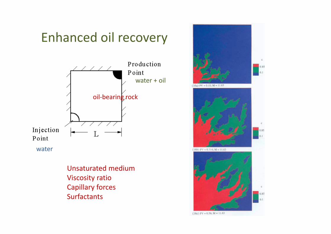
Enhanced oil recoveryEnhanced oil recovery
water + oil
oil‐bearing rock
Unsaturated medium
water
Unsaturated mediumViscosity ratioCapillary forcesSurfactantsSurfactants

Experimental results on the laboratory scaleExperimental results on the laboratory scale
Sorbie et al. (1997)
Viscous fingeringMiscible versus immiscible
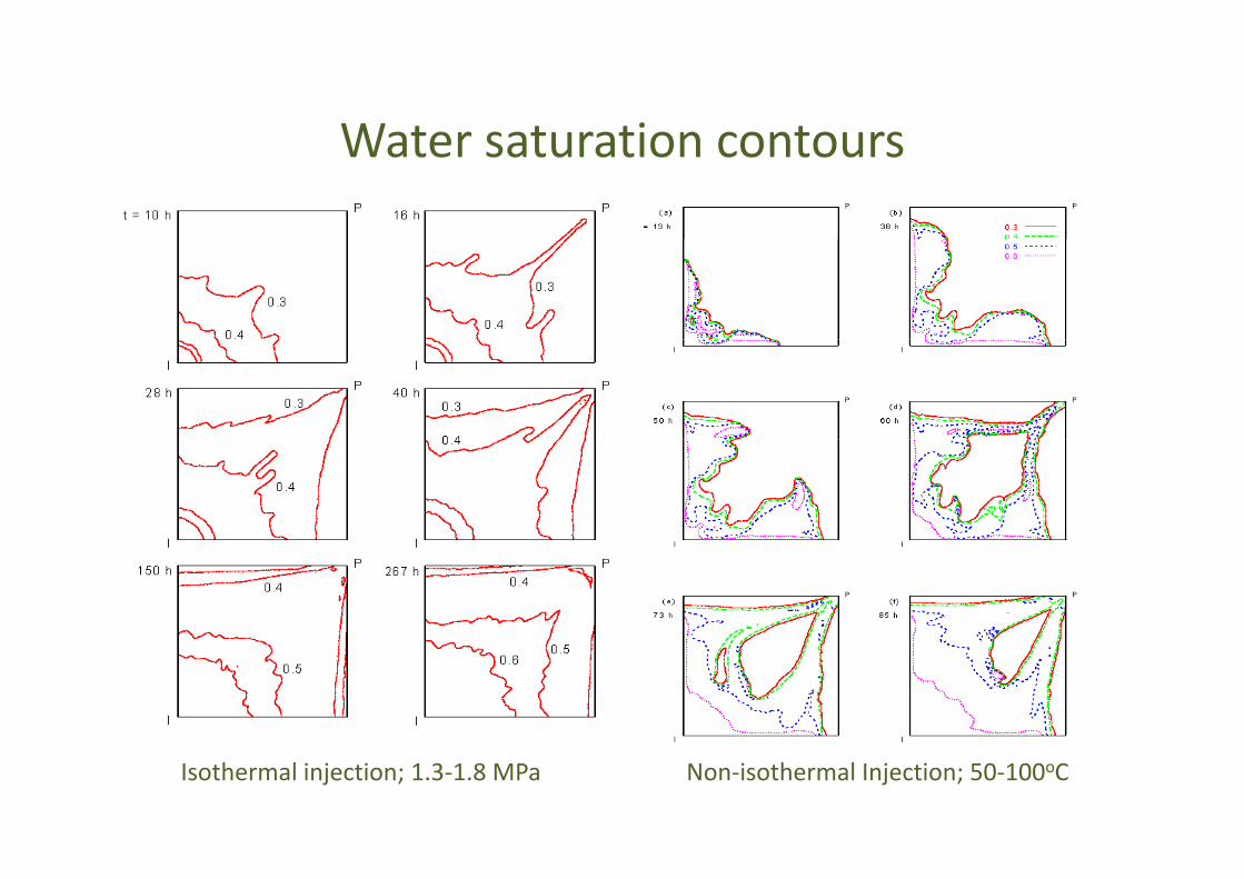
Water saturation contoursWater saturation contours
Isothermal injection; 1.3‐1.8 MPa Non‐isothermal Injection; 50‐100oC

Biomedicalapplications
o Oscillatory pressure loading and low wall shear can weaken the walls of the artery.
o Points of bifurcation are most vulnerable.
o Artery tends to balloon into a bulge.bulge.
o Pressure loading increases and wall shear decreases with deformation, creating a cascading effectcascading effect.
mayfieldclinic.commayfieldclinic.com

Coil EmbolizationCoil Embolization
Diameter 5‐10mmFrequency 1‐2 HzVelocity 0.5 – 1 m/sy /
Oscillatory flowyWall loading (pressure, shear)Wall deformation

Stream traces
Variable porosityVariable porosity model for porous and non‐porous regionsregionsCarreau‐Yashuda model for viscosity

Wall shear stress and pressureWall shear stress and pressure
Coil leaves pressure unchanged but decreases wall shear stress.

Regenerator modeling in a Stirling cryocooler
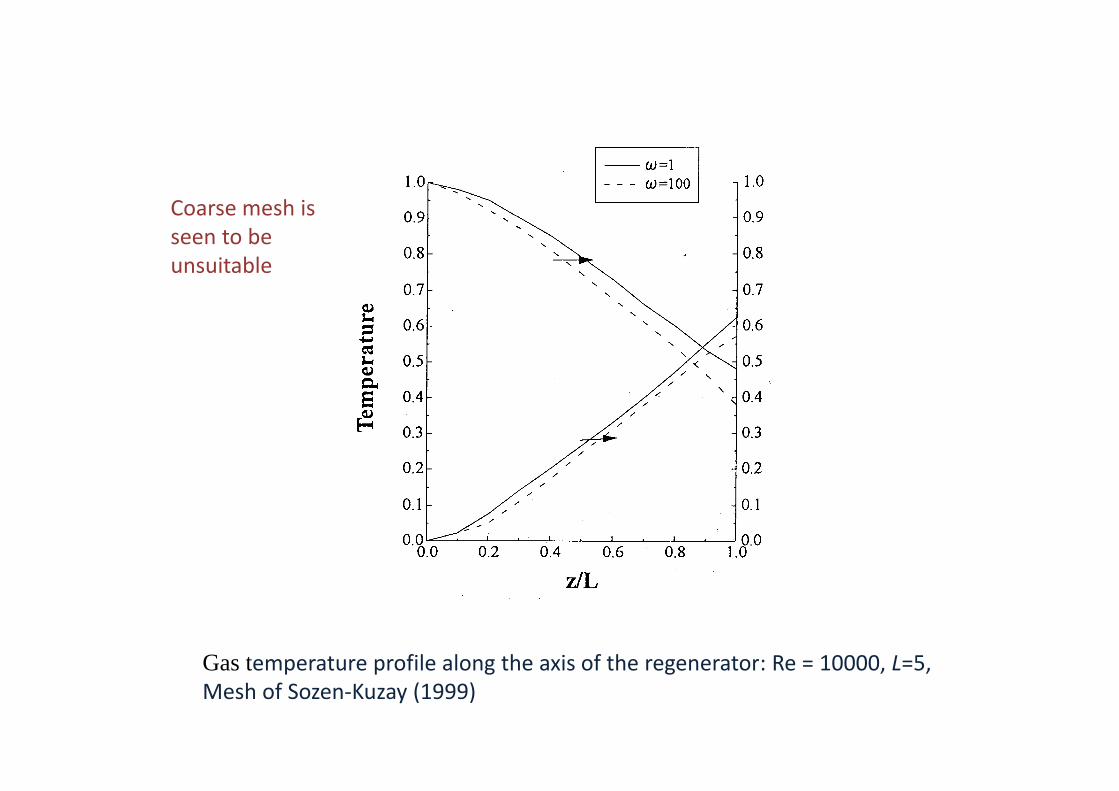
Coarse mesh is seen to be unsuitable
Gas temperature profile along the axis of the regenerator: Re = 10000 L=5Gas temperature profile along the axis of the regenerator: Re = 10000, L=5, Mesh of Sozen‐Kuzay (1999)

Thermal nonThermal non‐‐equilibrium equilibrium d ld lmodelmodel
Dense meshes are suitable but increasing mesh length increases sensitivity to frequency
Gas temperature profiles along the axis of the regenerator: (a) Re=10000, L=5 (b) Re=10000, L=10; Mesh of Chen‐Chang‐Huang (2001)

Methane Recovery from Hydrate Reservoirs by Si l D i i d COSimultaneous Depressurization and CO2
Sequestration
IncludesIncludes
o Multiphase – multi species transport
o Unsaturated porous mediao Non-isothermalo Dissociation and formation of hydrates (CH4, CO2)
o Secondary hydrates

Description of methane releaseDescription of methane release
o The reservoir has a porous structure filled with gas hydrates, free methane, and liquid waterD i ti t d l d t th l itho Depressurization at one end leads to methane release with the formation of a moving phase front
o CO2 (gas liquid) is injected from the other side and willo CO2 (gas-liquid) is injected from the other side and will displace methane towards the production well.
o Flow heat and mass transfer prevail in the reservoiro Flow, heat and mass transfer prevail in the reservoiro Conditions can be favorable for the formation solid CO2
hydrate that will stay in the reservoirhydrate that will stay in the reservoir

Phase equilibrium diagramPhase equilibrium diagram
stablestab e
Gas: CH4
unstable
Liquid: waterHydrate: water + CH4 as a solid unstablecrystal

Goals of the mathematical modelGoals of the mathematical model
• Methane release per unit time• Rate of formation of CO2 hydratesy• Effect of depressurization and injection
parameters – pressure and temperatureparameters pressure and temperature• Pressure, temperature, mass fraction
distribution within the reservoirdistribution within the reservoir

Equilibrium curvesEquilibrium curves
3 2280.6 280.6 ( 280.6)0.1588 0.6901 2.473 5.5134.447 4.447 4.447
meq
T T TP
methane
3 2( 278.9) ( 278.9) ( 278.9)0.06539 0.2738 0.9697 2.4793 057 3 057 3 057
ceq
T T TP
CO2 3.057 3.057 3.057

Equations of stateEquations of state
0.86 15 2
0.86 15 2
5.51721( ) 10 m , 0.11
4.84653( ) 10 m , 0.11abs lg lg
abs lg lg
K
K
.8 653( ) 0 , 0.abs lg lg
1ln
lrl lr lr gr
sk s s ss s
l gs s
1gn
gl
sk s s s
1rg gr lr gr
l g
k s s ss s
1cn
ll l
sP P s s s
1c ec lr lr gr
l g
P P s s ss s
m m c cg g g g
g m c cm c m mcg g g g g g

Equations of state (continued)Equations of state (continued)

Energy release during reactionsEnergy release during reactions
methane
9 8 7
( )
296.0 296.0 296.030100.0 - 12940.0 - 160100.014 42 14 42 14 42
fmhH T
T T T
methane
6 5
14.42 14.42 14.42
296.0 296.0 296.+ 69120.0 + 285800.0 - 119200.014.42 14.42
T T T
4
3 2
014.42
3 2296.0 296.0 296.0- 193900.0 + 68220.0 37070.0 +420100.014.42 14.42 14.42
T T T Jkg
( )fchH T CO2
8 7 6
5 4
278.15 278.15 278.152528.0 75.36 9727.02.739 2.739 2.739
278.15 278.15 278.15+ 1125 0 4000 0 - 4154 0
T T T
T T T
3
+ 1125.0 4000.0 - 4154.02.739 2.739 2.7
2
39
278.15 278.15+ 14430.0 6668.0 +389900.02.739 2.739
T T Jkg

Choice of formation parametersp
Uddin M, Coombe DA, Law D, Gunter WD. ASME J Energy Resources Technology, 2008;130(3):10.

Choice of process parametersp p
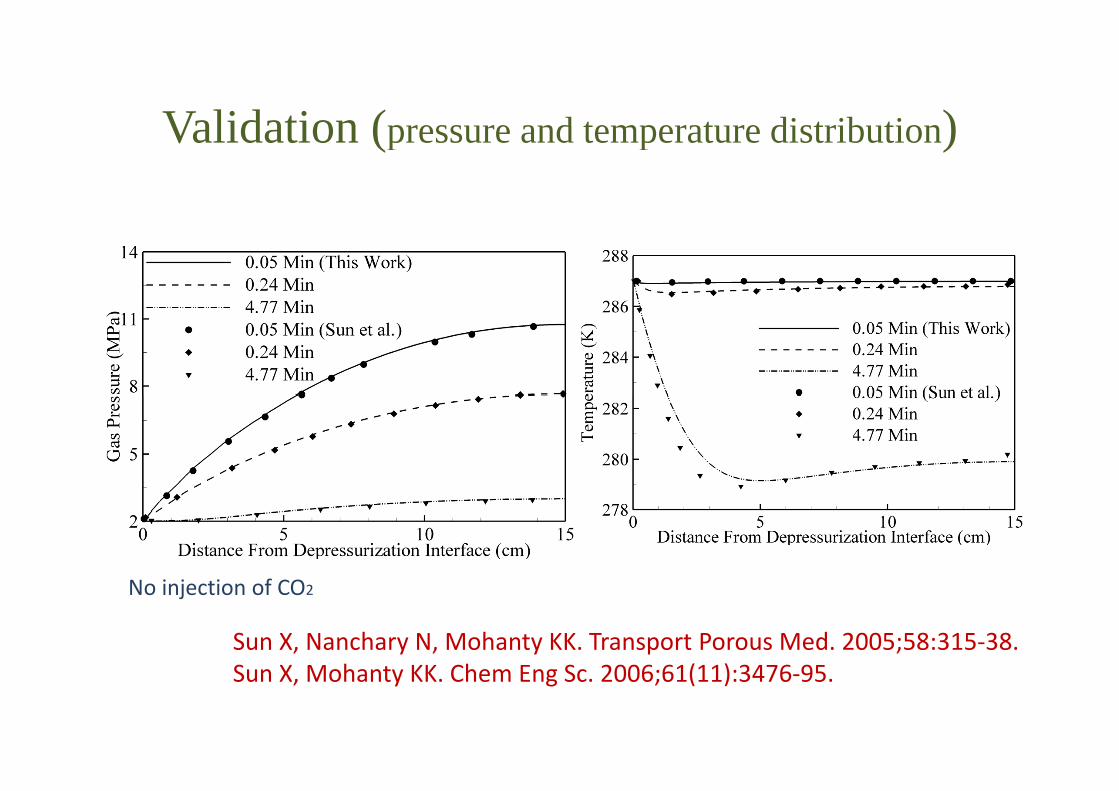
Validation (pressure and temperature distribution)Validation (pressure and temperature distribution)
Sun X, Nanchary N, Mohanty KK. Transport Porous Med. 2005;58:315‐38.S X M h KK Ch E S 2006 61(11) 3476 95
No injection of CO2
Sun X, Mohanty KK. Chem Eng Sc. 2006;61(11):3476‐95.

CH4 recovery and quantity of CO2 injectedy q y j
1 1
tions 0.8 0.8
60 d
30 days 15 days
Mol
eFr
act
0.6 0.6CH4
CO
60 days
Gas
Phas
eM
0 2
0.4
0 2
0.4CO2
60 days
Distance from Production Well (m)
G
0 20 40 60 80 1000
0.2
0
0.2
15 days30 days
Distance from Production Well (m)

ClosureClosure
Porous media applications are quite a few.Transport equations can be set upTransport equations can be set up. Simulation tools of CFD and related areas
b dcan be used.Number of parameters is large.Parameter estimation plays a central role in modeling and points towards need for g pcareful experiments.

Future directionsFuture directions
(a) Improved experiments (b) Fi ld l i l i(b) Field scale simulations(c) Radiation and combustion(d) d b d d b(d) Dependence on parameters can be reduced by
carrying out multi‐scale simulations.

AcknowledgementsAcknowledgements
D t t f S i d T h lDepartment of Science and TechnologyBoard of Research in Nuclear SciencesOil Industry Development BoardNational Gas Hydrates Program
Tanuja Sheorey M K DasTanuja Sheorey M.K. Das K.M. PillaiJyoti SwarupD b hi Mi hDebashis MishraP.P. MukherjeeAbhishek KhetanRahul SinghChandan Paul

THANK YOUTHANK YOU