flexray protocol controller conformance test … protocol controller conformance test implementation...
TRANSCRIPT
FlexRay Protocol Controller Conformance Test Implementation
Chu Liu*, Feng Luo
Clean Energy Automotive Engineering Center, College of Automotive Engineering, Tongji University, Shanghai 201804, China. * Corresponding author. Tel.: +86-21-69589482; email: [email protected] Manuscript submitted December 24, 2015; accepted June 14, 2016. doi: 10.17706/ijcee.2016.8.3.250-258
Abstract: The paper proposes a new approach for testing FlexRay communication controller at protocol level.
The implementation is realized on the basis of FlexRay international standard ISO 17458-3, which goes
beyond regular frame level testing that is provided by common FlexRay simulation and test tools. With the
help of arbitrary sequence generator implemented in FPGA and test engine implemented on computer, the
protocol related test cases such as static segment, dynamic segment, clock synchronization, wakeup and
startup are fully supported. This design is verified by oscilloscope as according to the specification.
Verification results show that the design and testing requirements are well satisfied.
Key words: FlexRay bus, automotive testing, automotive network, FPGA.
1. Introduction
FlexRay is an automotive network communications protocol initially developed by the FlexRay Consortium
to govern on-board automotive computing. It is designed to be faster and more reliable than established
standardized bus systems like CAN bus [1]. And today the FlexRay communications system has been
successfully implemented and FlexRay standard is now a set of ISO standards, from ISO 17458-1 to 17458-5.
The FlexRay ISO standard contains conformance test specifications for FlexRay Protocol and Physical Layer.
With the conformance tests released, semiconductor suppliers can submit their silicon solutions such as
communication controllers and physical layer devices to the conformance test partners. Upon successful
completion of the test, these devices will be qualified as conforming to the FlexRay ISO standard. For example,
a FlexRay controller is going to be compliant to FlexRay communication controller requirements in ISO
17458-2 [2], it should pass all the test cases defined in the FlexRay communication controller test
specification ISO 17458-3 [3]. Due to the complexity and professional degree of FlexRay conformance test,
currently there are only few test partners such as TÜV Nord [4] and C&S Group [5] all over the world. And
this paper introduces a new test method designed especially for the FlexRay conformance tests to overcome
the conformance testing difficulties.
2. The FlexRay Protocol
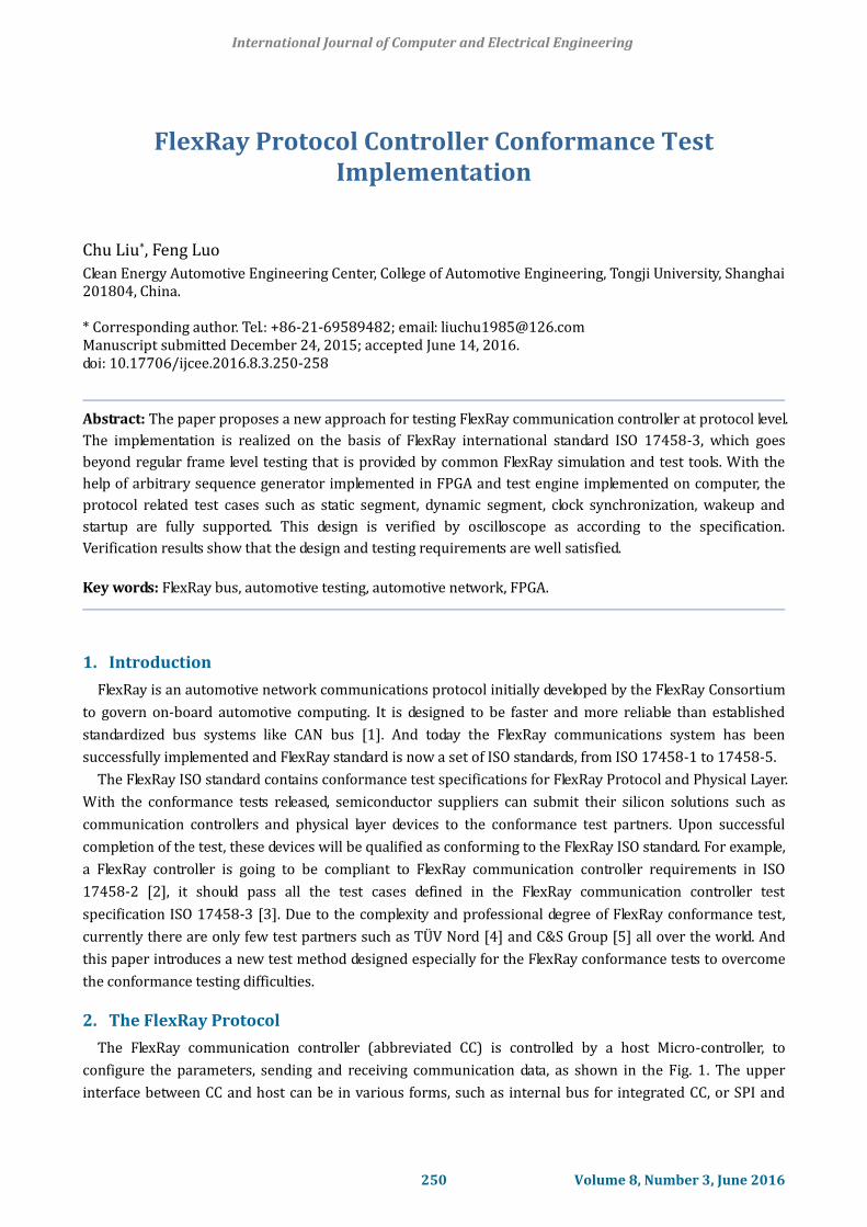
The FlexRay communication controller (abbreviated CC) is controlled by a host Micro-controller, to
configure the parameters, sending and receiving communication data, as shown in the Fig. 1. The upper
interface between CC and host can be in various forms, such as internal bus for integrated CC, or SPI and
International Journal of Computer and Electrical Engineering
250 Volume 8, Number 3, June 2016
external bus for a standalone CC. The lower interface between CC and bus driver are defined only by three
pins: TxD signal, RxD signal and TxEN signal [6], as shown in Fig. 2:
HostCommunication
Controller
Communication Data
Configuration Data &Status Information
Communication Controller
CHIProtocolEngine
Port Function
Port Function
Port Function
BusDriver
RxD
TxD
TxEN
RxD
TxD
TxEN
Fig. 1. Upper interface of CC. Fig. 2. Lower interface of CC.
3. Test System Structure
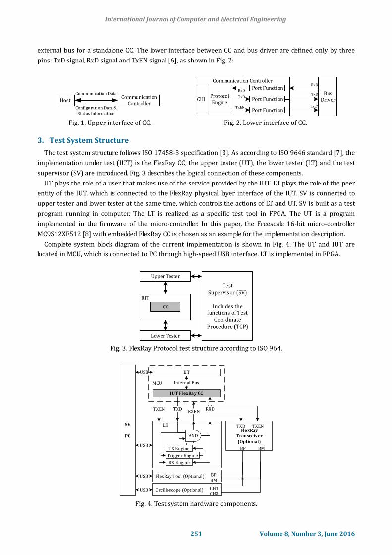
The test system structure follows ISO 17458-3 specification [3]. As according to ISO 9646 standard [7], the
implementation under test (IUT) is the FlexRay CC, the upper tester (UT), the lower tester (LT) and the test
supervisor (SV) are introduced. Fig. 3 describes the logical connection of these components.
UT plays the role of a user that makes use of the service provided by the IUT. LT plays the role of the peer
entity of the IUT, which is connected to the FlexRay physical layer interface of the IUT. SV is connected to
upper tester and lower tester at the same time, which controls the actions of LT and UT. SV is built as a test
program running in computer. The LT is realized as a specific test tool in FPGA. The UT is a program
implemented in the firmware of the micro-controller. In this paper, the Freescale 16-bit micro-controller
MC9S12XF512 [8] with embedded FlexRay CC is chosen as an example for the implementation description.
Complete system block diagram of the current implementation is shown in Fig. 4. The UT and IUT are
located in MCU, which is connected to PC through high-speed USB interface. LT is implemented in FPGA.
IUT
Upper Tester
CC
Lower Tester
TestSupervisor (SV)
Includes the functions of Test
Coordinate Procedure (TCP)
Fig. 3. FlexRay Protocol test structure according to ISO 964.
MCU
UT
IUT FlexRay CC
LT
Internal Bus
TXEN TXDRXEN
RXD
FlexRay Tool (Optional)
FlexRay Transceiver(Optional)
TXENTXD
BP BM
BPBM
SV
PC
USB
USB
USB
RX Engine
Trigger Engine
TX Engine
AND
Oscilloscope (Optional)USB CH1CH2
Fig. 4. Test system hardware components.
International Journal of Computer and Electrical Engineering
251 Volume 8, Number 3, June 2016
4. Implementation of LT
In this chapter, hardware and software components of the proposed testing approach of LT are defined.
Since FlexRay waveform can be decoded as raw bit stream, LT should include a waveform generator to
simulate ordinary FlexRay frame with glitches, or a FlexRay frame with wrong CRC value [9].
4.1. Functional System Blocks
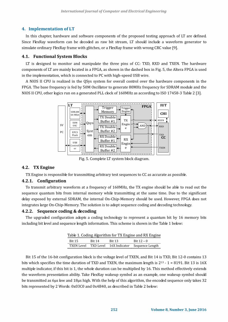
LT is designed to monitor and manipulate the three pins of CC: TXD, RXD and TXEN. The hardware
components of LT are mainly located in a FPGA, as shown in the dashed box in Fig. 5, the Altera FPGA is used
in the implementation, which is connected to PC with high-speed USB wire.
A NIOS II CPU is realized in the QSys system for overall control over the hardware components in the
FPGA. The base frequency is fed by 50M Oscillator to generate 80MHz frequency for SDRAM module and the
NIOS II CPU, other logics run on a generated PLL clock of 160MHz as according to ISO 17458-3 Table 2 [3].
LT FPGA
SDRAM64 Mbit
USBControll
er
SV
PC
TriggerMemory
TX Double Buffer #1
RX Double Buffer #1
RX Double Buffer #2
TriggerEngine
RX Engin
e
AND
IUT
CC
RXD
TXD
TXEN
CHI
50MOSC
EPCSFlash
Qsys
System
TX Double Buffer #2
RXENTX Engin
e
Fig. 5. Complete LT system block diagram.
4.2. TX Engine
TX Engine is responsible for transmitting arbitrary test sequences to CC as accurate as possible.
4.2.1. Configuration
To transmit arbitrary waveform at a frequency of 160MHz, the TX engine should be able to read out the
sequence quantum bits from internal memory while transmitting at the same time. Due to the significant
delay exposed by external SDRAM, the internal On-Chip-Memory should be used. However, FPGA does not
integrates large On-Chip-Memory. The solution is to adopt sequence coding and decoding technology.
4.2.2. Sequence coding & decoding
The upgraded configuration adopts a coding technology to represent a quantum bit by 16 memory bits
including bit level and sequence length information. This scheme is shown in the Table 1 below:
Table 1. Coding Algorithm for TX Engine and RX Engine
Bit 15 Bit 14 Bit 13 Bit 12 – 0
TXEN Level TXD Level 16X Indicator Sequence Length
Bit 15 of the 16-bit configuration block is the voltage level of TXEN, and Bit 14 is TXD, Bit 12-0 contains 13
bits which specifies the time duration of TXD and TXEN, the maximum length is 213 - 1 = 8191. Bit 13 is 16X
multiple indicator, if this bit is 1, the whole duration can be multiplied by 16. This method effectively extends
the waveform presentation ability. Take FlexRay wakeup symbol as an example, one wakeup symbol should
be transmitted as 6μs low and 18μs high. With the help of this algorithm, the encoded sequence only takes 32
bits represented by 2 Words: 0x03C0 and 0x4B40, as described in Table 2 below:
International Journal of Computer and Electrical Engineering
252 Volume 8, Number 3, June 2016
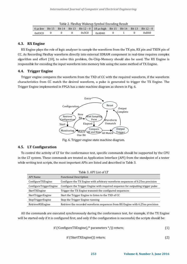
Table 2. FlexRay Wakeup Symbol Encoding Result
6 µs low Bit 15 Bit 14 Bit 13 Bit 12 – 0 18 µs high Bit 15 Bit 14 Bit 13 Bit 12 – 0
0x03C0 0 0 0 0x3C0 0x4B40 0 1 0 0xB40
4.3. RX Engine
RX Engine plays the role of logic analyzer to sample the waveform from the TX pin, RX pin and TXEN pin of
CC. As Recording FlexRay waveform directly into external SDRAM component in real-time requires complex
algorithm and effort [10], to solve this problem, On-Chip-Memory should also be used. The RX Engine is
responsible for encoding the input waveform into memory bits using the same method of TX Engine.
4.4. Trigger Engine
Trigger engine compares the waveform from the TXD of CC with the required waveform, if the waveform
characteristics from CC match the desired waveform, a pulse is generated to trigger the TX Engine. The
Trigger Engine implemented in FPGA has a state machine diagram as shown in Fig. 6.
Reset
RetrieveConfiguration
Monitoring
Wait SamplingPoint
CompareRX and Mem
OutputTrigger
Waveform Unmatch
OutputComplete
All MatchMatch One Bit
NewBit
Configuration
Start Elapsed
Entry
Fig. 6. Trigger engine state machine diagram.
4.5. LT Configuration
To control the activity of LT for the conformance test, specific commands should be supported by the CPU
in the LT system. These commands are treated as Application Interface (API) from the standpoint of a tester
while writing test scripts, the most important APIs are listed and described in Table 3.
Table 3. API List of LT
API Name Functional Description
ConfigureTXEngine Configure the TX Engine with arbitrary waveform sequences of 6.25ns precision
ConfigureTriggerEngine Configure the Trigger Engine with required sequence for outputting trigger pulse
StartTXEngine Trigger the TX Engine transmit the configured sequences
StartTriggerEngine Start the Trigger Engine to listen to the TXD of CC
StopTriggerEngine Stop the Trigger Engine running
RetrieveRXEngine Retrieve the recorded waveform sequences from RX Engine with 6.25ns precision
All the commands are executed synchronously during the conformance test, for example, if the TX Engine
will be started only if it is configured first, and only if the configuration is successful, the scripts should be:
if (!ConfigureTXEngine(/* parameters */)) return; (1)
if (!StartTXEngine()) return; (2)
International Journal of Computer and Electrical Engineering
253 Volume 8, Number 3, June 2016
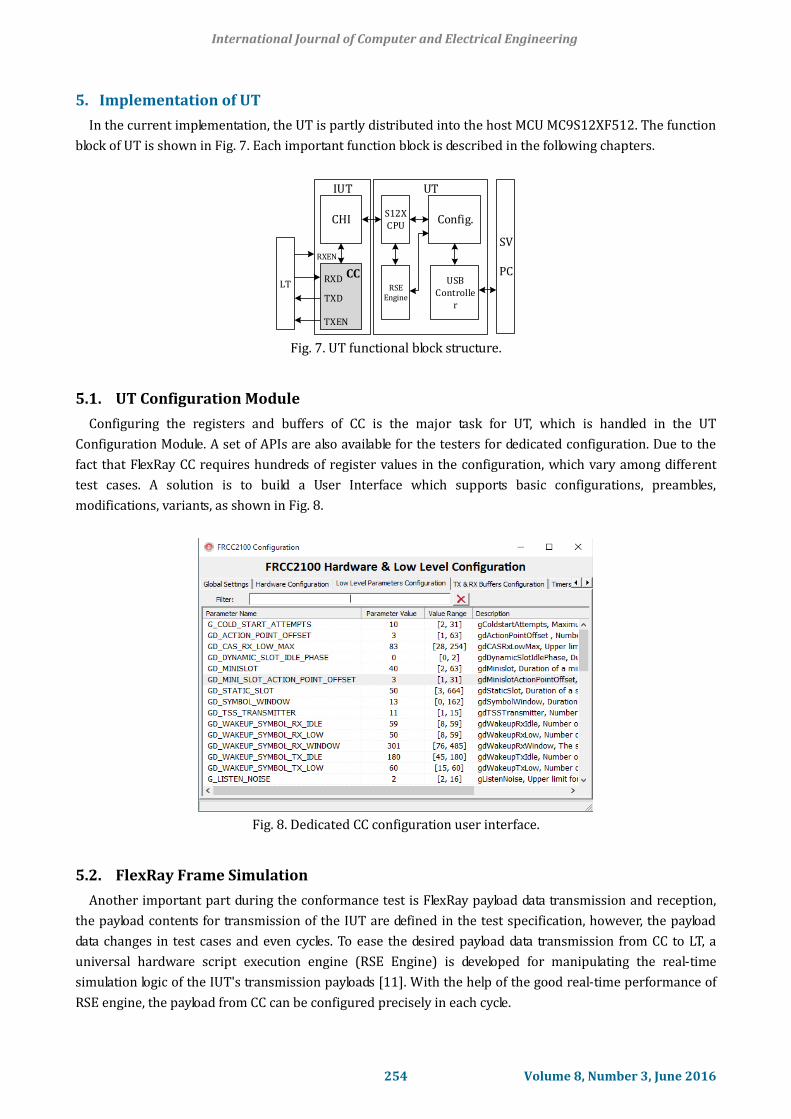
5. Implementation of UT
In the current implementation, the UT is partly distributed into the host MCU MC9S12XF512. The function
block of UT is shown in Fig. 7. Each important function block is described in the following chapters.
IUT
CC
RXEN
RXD
TXD
TXEN
CHI
LT
S12XCPU
RSEEngine
USBControlle
r
Config.
UT
SV
PC
Fig. 7. UT functional block structure.
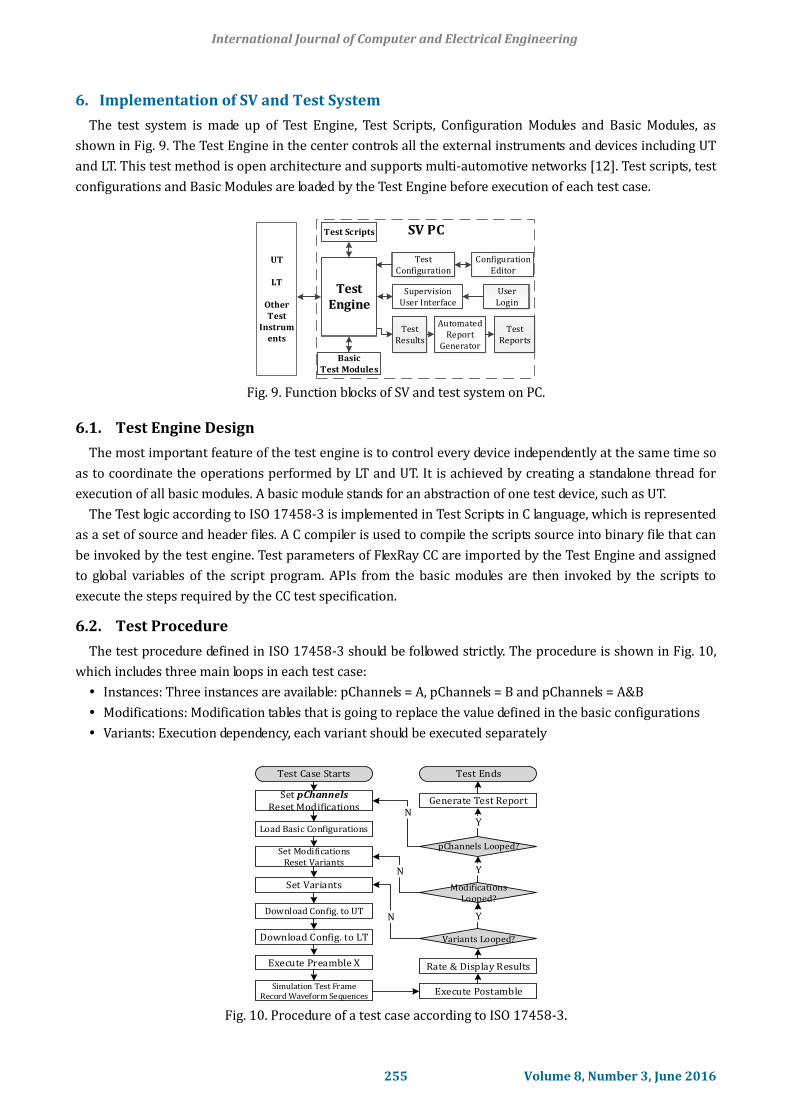
5.1. UT Configuration Module
Configuring the registers and buffers of CC is the major task for UT, which is handled in the UT
Configuration Module. A set of APIs are also available for the testers for dedicated configuration. Due to the
fact that FlexRay CC requires hundreds of register values in the configuration, which vary among different
test cases. A solution is to build a User Interface which supports basic configurations, preambles,
modifications, variants, as shown in Fig. 8.
Fig. 8. Dedicated CC configuration user interface.
5.2. FlexRay Frame Simulation
Another important part during the conformance test is FlexRay payload data transmission and reception,
the payload contents for transmission of the IUT are defined in the test specification, however, the payload
data changes in test cases and even cycles. To ease the desired payload data transmission from CC to LT, a
universal hardware script execution engine (RSE Engine) is developed for manipulating the real-time
simulation logic of the IUT's transmission payloads [11]. With the help of the good real-time performance of
RSE engine, the payload from CC can be configured precisely in each cycle.
International Journal of Computer and Electrical Engineering
254 Volume 8, Number 3, June 2016
6. Implementation of SV and Test System
The test system is made up of Test Engine, Test Scripts, Configuration Modules and Basic Modules, as
shown in Fig. 9. The Test Engine in the center controls all the external instruments and devices including UT
and LT. This test method is open architecture and supports multi-automotive networks [12]. Test scripts, test
configurations and Basic Modules are loaded by the Test Engine before execution of each test case.
SV PC
UT
LT
OtherTest
Instruments
TestEngine
Test Scripts
Basic Test Modules
User Login
SupervisionUser Interface
Test Results
Configuration Editor
TestConfiguration
AutomatedReport
Generator
Test Reports
Fig. 9. Function blocks of SV and test system on PC.
6.1. Test Engine Design
The most important feature of the test engine is to control every device independently at the same time so
as to coordinate the operations performed by LT and UT. It is achieved by creating a standalone thread for
execution of all basic modules. A basic module stands for an abstraction of one test device, such as UT.
The Test logic according to ISO 17458-3 is implemented in Test Scripts in C language, which is represented
as a set of source and header files. A C compiler is used to compile the scripts source into binary file that can
be invoked by the test engine. Test parameters of FlexRay CC are imported by the Test Engine and assigned
to global variables of the script program. APIs from the basic modules are then invoked by the scripts to
execute the steps required by the CC test specification.
6.2. Test Procedure
The test procedure defined in ISO 17458-3 should be followed strictly. The procedure is shown in Fig. 10,
which includes three main loops in each test case:
Instances: Three instances are available: pChannels = A, pChannels = B and pChannels = A&B
Modifications: Modification tables that is going to replace the value defined in the basic configurations
Variants: Execution dependency, each variant should be executed separately
Set pChannelsReset Modifications
Test Case Starts
Load Basic Configurations
Set ModificationsReset Variants
Set Variants
Download Config. to UT
Download Config. to LT
Execute Preamble X
Simulation Test FrameRecord Waveform Sequences Execute Postamble
Rate & Display Results
Variants Looped?
Modifications Looped?
pChannels Looped?
Generate Test Report
Test Ends
Y
Y
Y
N
N
N
Fig. 10. Procedure of a test case according to ISO 17458-3.
International Journal of Computer and Electrical Engineering
255 Volume 8, Number 3, June 2016
If there are 3 instances, 2 modifications and 3 variants, the total execution count should be 3 * 2 * 3 = 18.
All the parameter loading and loop switching are handled by the basic module DLL module.
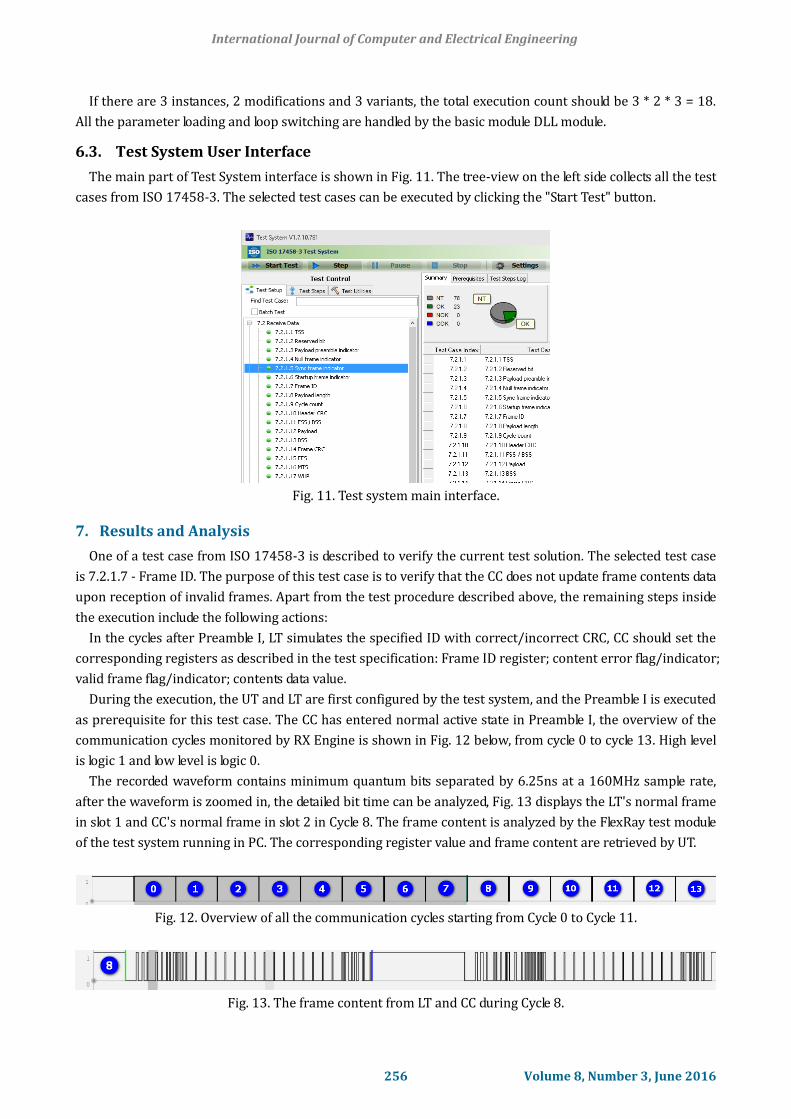
6.3. Test System User Interface
The main part of Test System interface is shown in Fig. 11. The tree-view on the left side collects all the test
cases from ISO 17458-3. The selected test cases can be executed by clicking the "Start Test" button.
Fig. 11. Test system main interface.
7. Results and Analysis
One of a test case from ISO 17458-3 is described to verify the current test solution. The selected test case
is 7.2.1.7 - Frame ID. The purpose of this test case is to verify that the CC does not update frame contents data
upon reception of invalid frames. Apart from the test procedure described above, the remaining steps inside
the execution include the following actions:
In the cycles after Preamble I, LT simulates the specified ID with correct/incorrect CRC, CC should set the
corresponding registers as described in the test specification: Frame ID register; content error flag/indicator;
valid frame flag/indicator; contents data value.
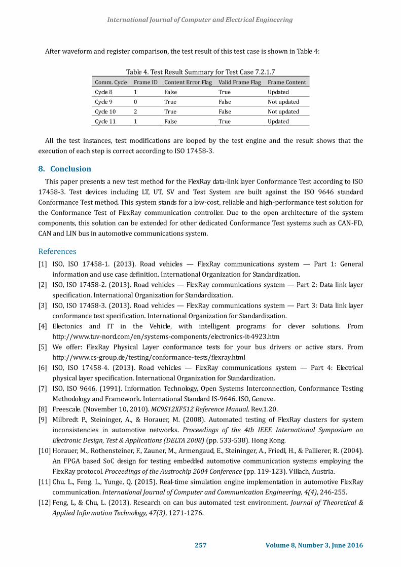
During the execution, the UT and LT are first configured by the test system, and the Preamble I is executed
as prerequisite for this test case. The CC has entered normal active state in Preamble I, the overview of the
communication cycles monitored by RX Engine is shown in Fig. 12 below, from cycle 0 to cycle 13. High level
is logic 1 and low level is logic 0.
The recorded waveform contains minimum quantum bits separated by 6.25ns at a 160MHz sample rate,
after the waveform is zoomed in, the detailed bit time can be analyzed, Fig. 13 displays the LT's normal frame
in slot 1 and CC's normal frame in slot 2 in Cycle 8. The frame content is analyzed by the FlexRay test module
of the test system running in PC. The corresponding register value and frame content are retrieved by UT.
Fig. 12. Overview of all the communication cycles starting from Cycle 0 to Cycle 11.
Fig. 13. The frame content from LT and CC during Cycle 8.
International Journal of Computer and Electrical Engineering
256 Volume 8, Number 3, June 2016
After waveform and register comparison, the test result of this test case is shown in Table 4:
Table 4. Test Result Summary for Test Case 7.2.1.7
Comm. Cycle Frame ID Content Error Flag Valid Frame Flag Frame Content
Cycle 8 1 False True Updated
Cycle 9 0 True False Not updated
Cycle 10 2 True False Not updated
Cycle 11 1 False True Updated
All the test instances, test modifications are looped by the test engine and the result shows that the
execution of each step is correct according to ISO 17458-3.
8. Conclusion
This paper presents a new test method for the FlexRay data-link layer Conformance Test according to ISO
17458-3. Test devices including LT, UT, SV and Test System are built against the ISO 9646 standard
Conformance Test method. This system stands for a low-cost, reliable and high-performance test solution for
the Conformance Test of FlexRay communication controller. Due to the open architecture of the system
components, this solution can be extended for other dedicated Conformance Test systems such as CAN-FD,
CAN and LIN bus in automotive communications system.
References
[1] ISO, ISO 17458-1. (2013). Road vehicles — FlexRay communications system — Part 1: General
information and use case definition. International Organization for Standardization.
[2] ISO, ISO 17458-2. (2013). Road vehicles — FlexRay communications system — Part 2: Data link layer
specification. International Organization for Standardization.
[3] ISO, ISO 17458-3. (2013). Road vehicles — FlexRay communications system — Part 3: Data link layer
conformance test specification. International Organization for Standardization.
[4] Electonics and IT in the Vehicle, with intelligent programs for clever solutions. From
http://www.tuv-nord.com/en/systems-components/electronics-it-4923.htm
[5] We offer: FlexRay Physical Layer conformance tests for your bus drivers or active stars. From
http://www.cs-group.de/testing/conformance-tests/flexray.html
[6] ISO, ISO 17458-4. (2013). Road vehicles — FlexRay communications system — Part 4: Electrical
physical layer specification. International Organization for Standardization.
[7] ISO, ISO 9646. (1991). Information Technology, Open Systems Interconnection, Conformance Testing
Methodology and Framework. International Standard IS-9646. ISO, Geneve.
[8] Freescale. (November 10, 2010). MC9S12XF512 Reference Manual. Rev.1.20.
[9] Milbredt P., Steininger, A., & Horauer, M. (2008). Automated testing of FlexRay clusters for system
inconsistencies in automotive networks. Proceedings of the 4th IEEE International Symposium on
Electronic Design, Test & Applications (DELTA 2008) (pp. 533-538). Hong Kong.
[10] Horauer, M., Rothensteiner, F., Zauner, M., Armengaud, E., Steininger, A., Friedl, H., & Pallierer, R. (2004).
An FPGA based SoC design for testing embedded automotive communication systems employing the
FlexRay protocol. Proceedings of the Austrochip 2004 Conference (pp. 119-123). Villach, Austria.
[11] Chu. L., Feng. L., Yunge, Q. (2015). Real-time simulation engine implementation in automotive FlexRay
communication. International Journal of Computer and Communication Engineering, 4(4), 246-255.
[12] Feng, L, & Chu, L. (2013). Research on can bus automated test environment. Journal of Theoretical &
Applied Information Technology, 47(3), 1271-1276.
International Journal of Computer and Electrical Engineering
257 Volume 8, Number 3, June 2016
Chu Liu was born in Fujian, China in July 1985. He received his master’s degree in
automotive electronics in March 2011 at Clean Energy Automotive Engineering Center,
College of Automotive Engineering, Tongji University, Shanghai, China.
He is now a PhD research student in Clean Energy Automotive Engineering Center in
Tongji University in Shanghai, China. His research interests include automotive network
communication, vehicle to vehicle communication and intelligent vehicle.
Dr. Chu Liu has joined in the “Tongji-Freescale” joint laboratory and “Tongji-ihr” joint
laboratory and he is doing research in the automotive network field for many years.
Feng Luo was born in Shanxi, China on September 1969. He received his PhD degree in
aircraft control engineering from Northwestern Polytechnical University in 2000, Shanxi,
China. From 2000 to 2002, he did his postdoctoral research work in the Department of
Automotive Engineering of Tsinghua University in Beijing, China.
He came to Tongji University in 2002, he is now a professor in automotive engineering
study of Tongji University. His research interests include automotive networks, automotive
electronic system control, vehicle to vehicle communication.
Prof. Feng Luo is now the director of “Tongji-Freescale” joint laboratory and “Tongji-ihr” joint laboratory.
His automotive development group has been participating in numerous national and international research
projects in these areas for more than 10 years.
International Journal of Computer and Electrical Engineering
258 Volume 8, Number 3, June 2016