flexoelectric effect and human eye perception on the … effect and human eye perception on the...
TRANSCRIPT
Flexoelectric effect and human eye perception on the image flickering of a liquid crystal display
Haiwei Chena, Fenglin Penga, Minggang Hua,b and Shin-Tson Wua*aCREOL, The College of Optics and Photonics, University of Central Florida, Orlando, FL 32816, USA; bXi’an ModernChemistry Research Institute, Xi’an 710065, China
(Received 26 May 2015; accepted 9 June 2015)
We investigated the flexoelectric effect of a fringe field switching liquid crystal (LC) cell and characterised theresultant image flicker with different LC mixtures at different frame rates. Incorporating with human eyeperception of 10 observers, we found that LC mixtures with a dielectric anisotropy smaller than ~7 lead tounnoticeable image flicker at 60 frames per second. The obtained flicker sensitivity line serves as importantguidelines for optimising LC materials and display devices.
Keywords: liquid crystal display; fringe field switching; flexoelectric effect
1. Introduction
Thin-film transistor (TFT) liquid crystal display(LCD) is ubiquitous nowadays; its applicationscover from televisions, computers, smart phones,tablets, to car navigators.[1] Among many LCmodes developed, fringe field switching (FFS) hasbecome the main approach for mobile displays.[2–5]The device configuration of an FFS cell consists ofpatterned pixel electrodes and a planar common elec-trode, separated by a thin passivation layer. In thevoltage-off state (V = 0), the LC directors are homo-geneously aligned. As the voltage increases, the LCdirectors are gradually reoriented by the electric field,leading to a bright state. Since the electric-field-inducedmolecular reorientation takes place primarily in thehorizontal direction, FFS mode exhibits some out-standing features, including high-transmittance, wide-viewing angle, weak colour shift and robust to touchpressure.[4–6] Both positive (p-FFS) and negative(n-FFS) dielectric anisotropy (Δε) LC materials canbe used in FFS.[5–8] Each mode has its own prosand cons. For example, for a given | Δε | value, positiveLCs have an ~ 2X lower viscosity so that p-FFS has afaster response time than n-FFS, provided that the cellgap remains the same. This advantage is amplified to~5X at low temperature (–20°C).[6] On the other hand,n-FFS has higher transmittance, single gamma curveand unnoticeable image flicker because the LC direc-tors are more uniformly reoriented by the electric field.[7,8] For TFT LCDs, the common materials employedare rod-like low-molecular-weight nematic LCs; [9–11]while other kinds of LCs, such as bend-core molecules,[12,13] are rarely used because of their high viscosityand flexoelectricity. Thus, here we focus on rod-likelow-viscosity nematic LCs.
Image flickering is an important issue as it affectsthe visual quality of a display device.[14] For exam-ple, Apple iPhone 6 uses two-domain n-FFS in orderto improve the transmittance and viewing angle, whilereducing image flickering and colour shift. Severalfactors can cause image flickering, like TFT leakagecurrent and inadequate voltage holding ratio, but thedominant factors are flexoelectric effect (FEE) of theLC and human eye perception. Until now, there areonly a few studies on this effect in FFS cell, and mostof the previous reports concentrate on the observationand confirmation rather than understanding thedetailed physical mechanisms.[14–16] Thus, a sys-tematic study to understand the mechanisms, quantifythe effect and then find solutions is urgently needed.
In this paper, we investigate the FEE of FFS cellsystematically. Its origin can be described by theGibbs free energy. We evaluate the image flicker ofFFS cells with different | Δε | LC materials and dif-ferent frame rates. Our experimental results indicatethat keeping Δε ≤ 7.2 could suppress the flicker tounnoticeable level at 60 frames per second (fps).Incorporating with human eye perception of 10observes, we obtain a flicker sensitivity line for FFScell, which serves as important guidelines for optimis-ing LC materials and display devices.
2. FEE of FFS LC cell
FEE was first discovered and analysed by Meyer [17]and experimentally observed by Schmidt et al. [18]; itis a kind of interaction between LC and external force(e.g. mechanical stress or electric field). Differentfrom conventional dielectric coupling, FEE still existseven when the dielectric anisotropy of the LC is zero
*Corresponding author. Email: [email protected]
Liquid Crystals, 2015Vol. 42, No. 12, 1730–1737, http://dx.doi.org/10.1080/02678292.2015.1061714
© 2015 Taylor & Francis
Dow
nloa
ded
by [
Uni
vers
ity o
f C
entr
al F
lori
da]
at 0
9:22
30
Nov
embe
r 20
15
(e.g. bent-core structures [12,13]). According toMeyer’s analysis, the polarisation induced by FEE isas follows:
~Pf ¼ e11~nð� �~nÞ þ e33ð��~nÞ �~n; (1)
where e11 and e33 are flexoelectric coefficients, and ~nis the unit vector of the LC orientation. FromEquation (1), e11 and e33 are the two dominant factorsgoverning the splay and bend deformations. Somemethods for measuring e11 and e33 have been deve-loped, although they are not simple.[19–22] Ingeneral, FEE is strong in a system whose moleculespossess a large shape polarity as well as a largepermanent dipole moment, which means there is acorrelation between flexoelectric coefficients anddielectric anisotropy.[17,19]
In an FFS cell, the electric field is strong and non-uniform in both lateral and longitudinal directions. Asa result, the rod-like LCs are splayed and bent, whichin turn causes a non-negligible flexoelectric polarisa-tion. Thus, the total Gibbs free energy consists of threeterms: elastic, dielectric and flexoelectric [23]:
FElastic ¼ 1
2K11½� �~n�2 þ 1
2K22½~n � ð��~nÞ�2
þ 1
2K33½~n� ð��~nÞ�2; (2)
FDielectric ¼ � 1
2ε0Δε½~n �~E�2; (3)
Fflexo ¼ �½e11~nð� �~nÞ þ e33ð��~nÞ �~n� �~E; (4)
F ¼ FElastic þ FDielectric þ FFlexo; (5)
where FElastic is the Frank elastic free energy density,FDielectric is free energy associated with dielectric
coupling, FFlexo is the free energy contributed fromflexoelectricity, K11, K22 and K33 are the splay, twistand bend elastic constants.
In an FFS cell, the electric field is not uniform inboth lateral and longitudinal directions. As a result,finding analytical solution for the total Gibbsfree energy (Equation (5)) is rather complicated.Moreover, the image flicker also depends on thehuman eye sensitivity. Thus, we are taking the experi-mental approach to establish correlations betweenimage flickering and LC material properties andTFT frame rate. Our objective is to suppress flickerto unnoticeable level.
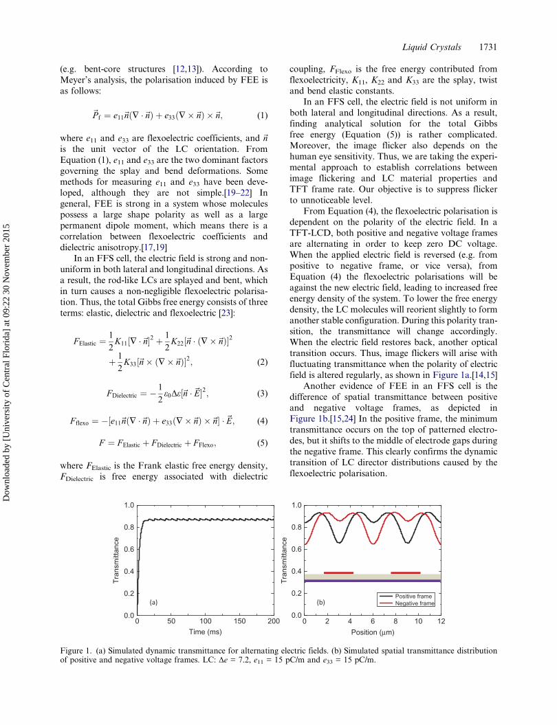
From Equation (4), the flexoelectric polarisation isdependent on the polarity of the electric field. In aTFT-LCD, both positive and negative voltage framesare alternating in order to keep zero DC voltage.When the applied electric field is reversed (e.g. frompositive to negative frame, or vice versa), fromEquation (4) the flexoelectric polarisations will beagainst the new electric field, leading to increased freeenergy density of the system. To lower the free energydensity, the LC molecules will reorient slightly to formanother stable configuration. During this polarity tran-sition, the transmittance will change accordingly.When the electric field restores back, another opticaltransition occurs. Thus, image flickers will arise withfluctuating transmittance when the polarity of electricfield is altered regularly, as shown in Figure 1a.[14,15]
Another evidence of FEE in an FFS cell is thedifference of spatial transmittance between positiveand negative voltage frames, as depicted inFigure 1b.[15,24] In the positive frame, the minimumtransmittance occurs on the top of patterned electro-des, but it shifts to the middle of electrode gaps duringthe negative frame. This clearly confirms the dynamictransition of LC director distributions caused by theflexoelectric polarisation.
(b)(a)
0.0
0.2
0.4
0.6
0.8
1.0
Tra
nsm
ittan
ce
Position (μm)
Positive frameNegative frame
0 2 4 6 8 10 120 50 100 150 2000.0
0.2
0.4
0.6
0.8
1.0
Tra
nsm
ittan
ce
Time (ms)
Figure 1. (a) Simulated dynamic transmittance for alternating electric fields. (b) Simulated spatial transmittance distributionof positive and negative voltage frames. LC: Δe = 7.2, e11 = 15 pC/m and e33 = 15 pC/m.
Liquid Crystals 1731
Dow
nloa
ded
by [
Uni
vers
ity o
f C
entr
al F
lori
da]
at 0
9:22
30
Nov
embe
r 20
15
3. Experimental results
In experiment, we investigate FEE from differentinfluencing factors, including driving frequency,dielectric anisotropy, viscosity and human eye sensi-tivity. An FFS cell with electrode width w = 3 μm,electrode gap l = 4 μm and cell gap d = 3.5 μm wasemployed. Also, five different LC mixtures werechosen to investigate the FEE, and their physicalproperties are listed in Table 1. Here, we define aflicker parameter as F = ΔT/T = (Tmax – Tmin)/Tave
to quantify the transmittance change during frameinversion.
Figure 2a shows the measured voltage–transmit-tance (VT) curves for two LC mixtures with differentdielectric anisotropies (Δε = 10 and Δε = 4.4). With asmaller Δε, both on-state voltage and peak transmit-tance increase.[6] Next, we investigated the voltage-dependent image flicker for both materials, as shownin Figure 2b. They exhibit a similar trend: as theoperation voltage increases, the image flickerdecreases first and then climbs up. In the low grey-level region, although the image flicker (quantified bythe F-value) seems large (because of small denomina-tor), the actual ΔT is relatively small. As a result, theflicker is hardly noticeable. In the middle grey-levelregion, T increases more rapidly than ΔT, resulting ina decreased F-value. However, this condition isreversed in the high grey-level region. Thus, in the
following sections, we will evaluate image flicker atthe on-state voltage, i.e. peak transmittance.
3.1. Frequency effect
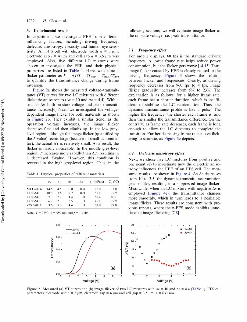
For mobile displays, 60 fps is the standard drivingfrequency. A lower frame rate helps reduce powerconsumption, but the flicker gets worse.[14,15] Thus,image flicker caused by FEE is closely related to thedriving frequency. Figure 3 shows the relationbetween flicker and frequencies. Clearly, as drivingfrequency decreases from 960 fps to 4 fps, imageflicker gradually increases from 5% to 23%. Theexplanation is as follows: for a higher frame rate,each frame has a shorter duration, which is insuffi-cient to stabilise the LC reorientation. Thus, thedynamic transmittance profile is like a pulse. Thehigher the frequency, the shorter each frame is, andthen the smaller the transmittance difference. On thecontrary, as frame rate decreases, each frame is longenough to allow the LC directors to complete thetransition. Further decreasing frame rate causes flick-ering to saturate, as Figure 3e depicts.
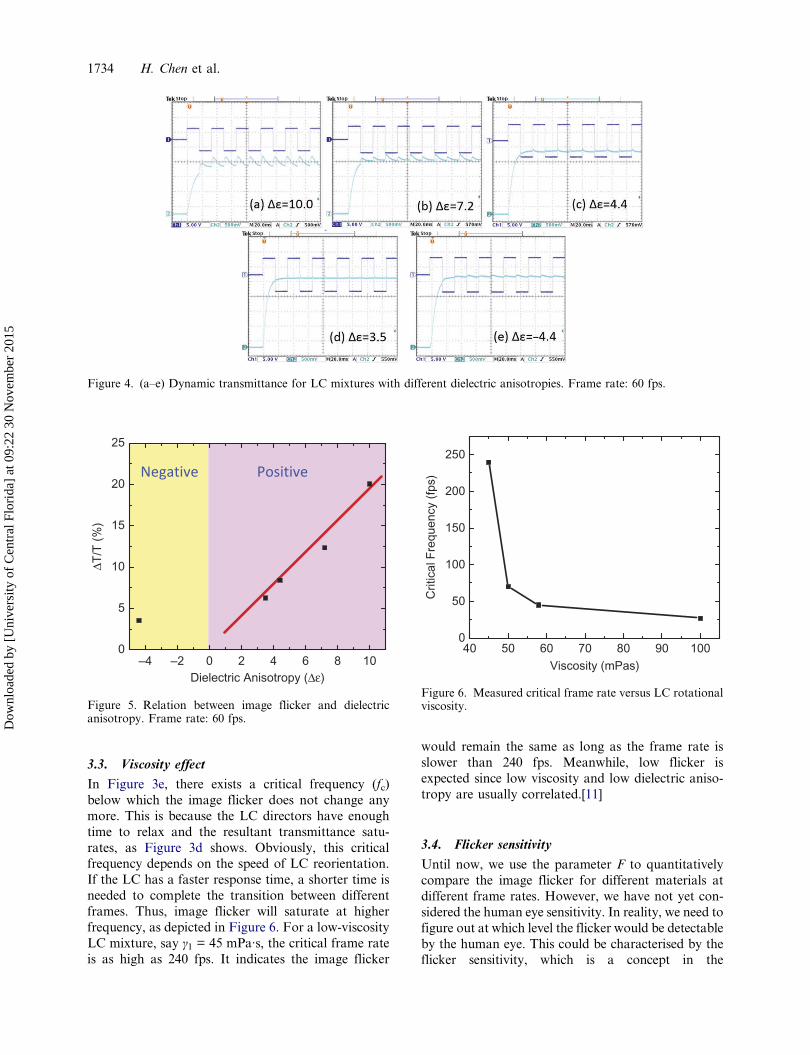
3.2. Dielectric anisotropy effect
Next, we chose five LC mixtures (four positive andone negative) to investigate how the dielectric aniso-tropy influences the FEE of an FFS cell. The mea-sured results are shown in Figure 4. As Δε decreasesfrom 10 to 3.5, the dynamic transmittance variationgets smaller, resulting in a suppressed image flicker.Meanwhile, when an LC mixture with negative Δε isemployed (Figure 4e), the transmittance changesmore smoothly, which in turn leads to a negligibleimage flicker. These results are consistent with pre-vious reports, where the n-FFS mode exhibits unno-ticeable image flickering.[7,8]
Table 1. Physical properties of different materials.
ε// ε\ Δε Δn γ1 (mPa·s) Tc (°C)
MLC-6686 14.5 4.5 10.0 0.098 102.0 71.0UCF-M1 10.8 3.6 7.2 0.099 58.1 77.9UCF-M2 7.3 2.9 4.4 0.100 50.4 80.1UCF-M3 6.2 2.7 3.5 0.103 45.1 77.9ZOC-7003 3.6 8.0 −4.4 0.103 101.0 79.0
Note: T = 23°C, λ = 550 nm and f = 1 kHz.
Figure 2. Measured (a) VT curves and (b) image flicker of two LC mixtures with Δε = 10 and Δε = 4.4 (Table 1). FFS cellparameters: electrode width = 3 μm, electrode gap = 4 μm and cell gap = 3.5 μm. λ = 633 nm.
1732 H. Chen et al.
Dow
nloa
ded
by [
Uni
vers
ity o
f C
entr
al F
lori
da]
at 0
9:22
30
Nov
embe
r 20
15
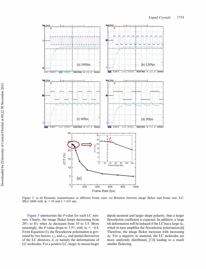
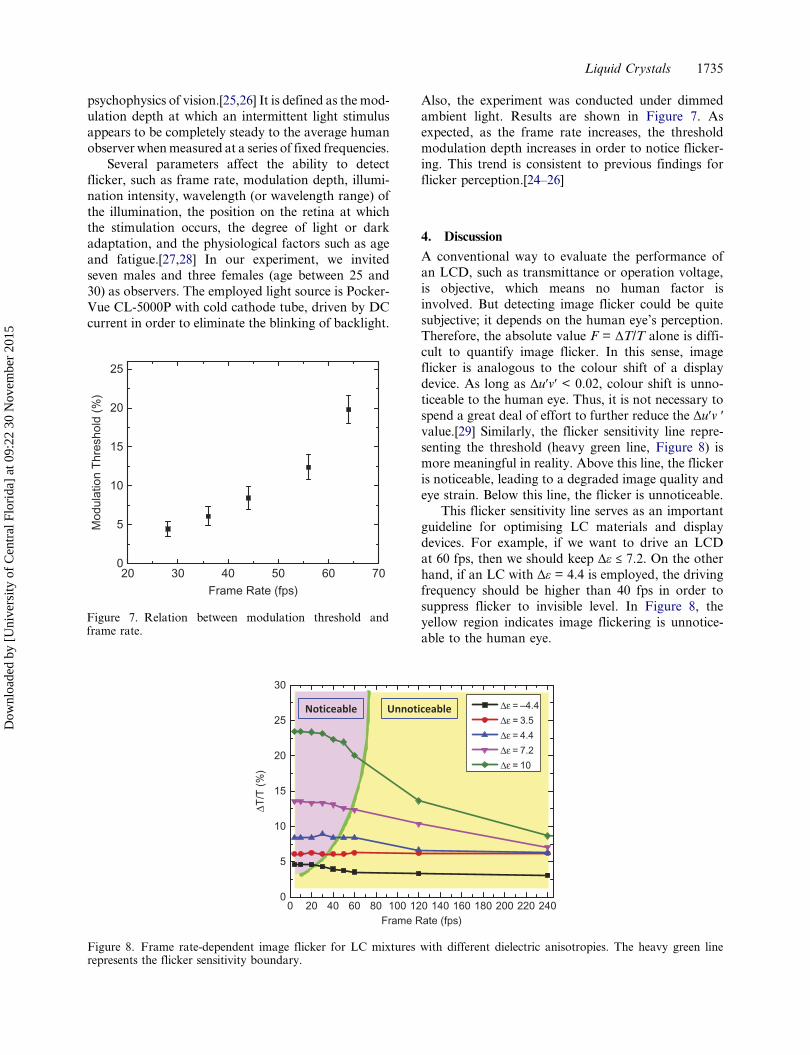
Figure 5 summarises the F-value for each LC mix-ture. Clearly, the image flicker keeps decreasing from20% to 6% when Δε decreases from 10 to 3.5. Moreamazingly, the F-value drops to 3.5% with Δε = −4.4.From Equation (1), the flexoelectric polarisation is gov-erned by two factors: e11 and e33, and spatial derivativesof the LC directors, ~n, or namely the deformations ofLCmolecules. For a positive LC, largerΔεmeans larger
dipole moment and larger shape polarity, thus a largerflexoelectric coefficient is expected. In addition, a largetilt deformation will be induced if the LC has a large Δε,which in turn amplifies the flexoelectric polarisation.[6]Therefore, the image flicker increases with increasingΔε. For a negative Δε material, the LC molecules aremore uniformly distributed, [7,8] leading to a muchsmaller flickering.
0
5
10
15
20
25
30
ΔT/T
(%
)
Frame Rate (fps)0 20 40 60 80 100 120
0 200 400 600 800 10000
5
10
15
20
25
30
ΔT/T
(%
)
Frame Rate (fps)
(b) 120fps(a) 240fps
(c) 60fps (d) 30fps
(e)
fc
Figure 3. (a–d) Dynamic transmittance at different frame rates. (e) Relation between image flicker and frame rate. LC:MLC-6686 with Δε = 10 and λ = 633 nm.
Liquid Crystals 1733
Dow
nloa
ded
by [
Uni
vers
ity o
f C
entr
al F
lori
da]
at 0
9:22
30
Nov
embe
r 20
15
3.3. Viscosity effect
In Figure 3e, there exists a critical frequency (fc)below which the image flicker does not change anymore. This is because the LC directors have enoughtime to relax and the resultant transmittance satu-rates, as Figure 3d shows. Obviously, this criticalfrequency depends on the speed of LC reorientation.If the LC has a faster response time, a shorter time isneeded to complete the transition between differentframes. Thus, image flicker will saturate at higherfrequency, as depicted in Figure 6. For a low-viscosityLC mixture, say γ1 = 45 mPa·s, the critical frame rateis as high as 240 fps. It indicates the image flicker
would remain the same as long as the frame rate isslower than 240 fps. Meanwhile, low flicker isexpected since low viscosity and low dielectric aniso-tropy are usually correlated.[11]
3.4. Flicker sensitivity
Until now, we use the parameter F to quantitativelycompare the image flicker for different materials atdifferent frame rates. However, we have not yet con-sidered the human eye sensitivity. In reality, we need tofigure out at which level the flicker would be detectableby the human eye. This could be characterised by theflicker sensitivity, which is a concept in the
PositiveNegative
–4 –2 0 2 4 6 8 100
5
10
15
20
25
ΔT/T
(%
)
Dielectric Anisotropy (Δε)
Figure 5. Relation between image flicker and dielectricanisotropy. Frame rate: 60 fps.
40 50 60 70 80 90 1000
50
100
150
200
250
Crit
ical
Fre
quen
cy (
fps)
Viscosity (mPas)
Figure 6. Measured critical frame rate versus LC rotationalviscosity.
Figure 4. (a–e) Dynamic transmittance for LC mixtures with different dielectric anisotropies. Frame rate: 60 fps.
1734 H. Chen et al.
Dow
nloa
ded
by [
Uni
vers
ity o
f C
entr
al F
lori
da]
at 0
9:22
30
Nov
embe
r 20
15
psychophysics of vision.[25,26] It is defined as the mod-ulation depth at which an intermittent light stimulusappears to be completely steady to the average humanobserver whenmeasured at a series of fixed frequencies.
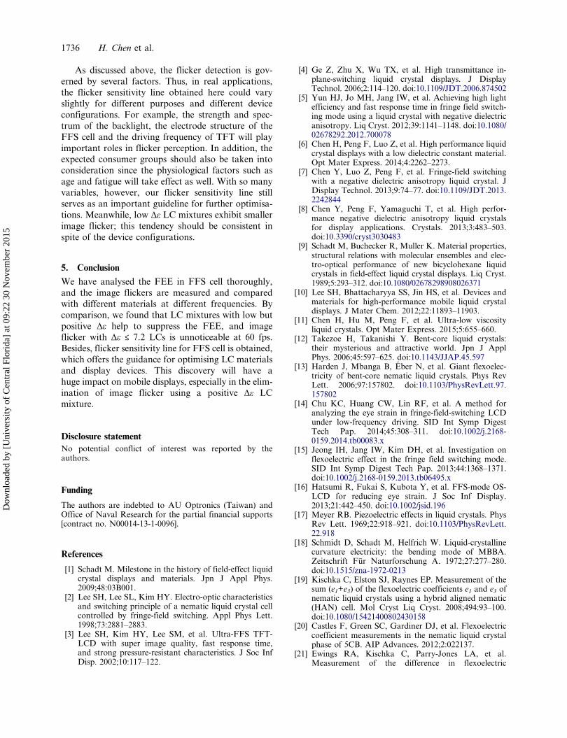
Several parameters affect the ability to detectflicker, such as frame rate, modulation depth, illumi-nation intensity, wavelength (or wavelength range) ofthe illumination, the position on the retina at whichthe stimulation occurs, the degree of light or darkadaptation, and the physiological factors such as ageand fatigue.[27,28] In our experiment, we invitedseven males and three females (age between 25 and30) as observers. The employed light source is Pocker-Vue CL-5000P with cold cathode tube, driven by DCcurrent in order to eliminate the blinking of backlight.
Also, the experiment was conducted under dimmedambient light. Results are shown in Figure 7. Asexpected, as the frame rate increases, the thresholdmodulation depth increases in order to notice flicker-ing. This trend is consistent to previous findings forflicker perception.[24–26]
4. Discussion
A conventional way to evaluate the performance ofan LCD, such as transmittance or operation voltage,is objective, which means no human factor isinvolved. But detecting image flicker could be quitesubjective; it depends on the human eye’s perception.Therefore, the absolute value F = ΔT/T alone is diffi-cult to quantify image flicker. In this sense, imageflicker is analogous to the colour shift of a displaydevice. As long as Δu′v′ < 0.02, colour shift is unno-ticeable to the human eye. Thus, it is not necessary tospend a great deal of effort to further reduce the Δu′v ′value.[29] Similarly, the flicker sensitivity line repre-senting the threshold (heavy green line, Figure 8) ismore meaningful in reality. Above this line, the flickeris noticeable, leading to a degraded image quality andeye strain. Below this line, the flicker is unnoticeable.
This flicker sensitivity line serves as an importantguideline for optimising LC materials and displaydevices. For example, if we want to drive an LCDat 60 fps, then we should keep Δε ≤ 7.2. On the otherhand, if an LC with Δε = 4.4 is employed, the drivingfrequency should be higher than 40 fps in order tosuppress flicker to invisible level. In Figure 8, theyellow region indicates image flickering is unnotice-able to the human eye.
20 30 40 50 60 700
5
10
15
20
25
Mod
ulat
ion
Thr
esho
ld (
%)
Frame Rate (fps)
Figure 7. Relation between modulation threshold andframe rate.
Noticeable Unnoticeable
0 20 40 60 80 100 120 140 160 180 200 220 2400
5
10
15
20
25
30
ΔT/T
(%
)
Frame Rate (fps)
Δε = –4.4
Δε = 3.5
Δε = 4.4
Δε = 7.2
Δε = 10
Figure 8. Frame rate-dependent image flicker for LC mixtures with different dielectric anisotropies. The heavy green linerepresents the flicker sensitivity boundary.
Liquid Crystals 1735
Dow
nloa
ded
by [
Uni
vers
ity o
f C
entr
al F
lori
da]
at 0
9:22
30
Nov
embe
r 20
15
As discussed above, the flicker detection is gov-erned by several factors. Thus, in real applications,the flicker sensitivity line obtained here could varyslightly for different purposes and different deviceconfigurations. For example, the strength and spec-trum of the backlight, the electrode structure of theFFS cell and the driving frequency of TFT will playimportant roles in flicker perception. In addition, theexpected consumer groups should also be taken intoconsideration since the physiological factors such asage and fatigue will take effect as well. With so manyvariables, however, our flicker sensitivity line stillserves as an important guideline for further optimisa-tions. Meanwhile, low Δε LC mixtures exhibit smallerimage flicker; this tendency should be consistent inspite of the device configurations.
5. Conclusion
We have analysed the FEE in FFS cell thoroughly,and the image flickers are measured and comparedwith different materials at different frequencies. Bycomparison, we found that LC mixtures with low butpositive Δε help to suppress the FEE, and imageflicker with Δε ≤ 7.2 LCs is unnoticeable at 60 fps.Besides, flicker sensitivity line for FFS cell is obtained,which offers the guidance for optimising LC materialsand display devices. This discovery will have ahuge impact on mobile displays, especially in the elim-ination of image flicker using a positive Δε LCmixture.
Disclosure statementNo potential conflict of interest was reported by theauthors.
Funding
The authors are indebted to AU Optronics (Taiwan) andOffice of Naval Research for the partial financial supports[contract no. N00014-13-1-0096].
References
[1] Schadt M. Milestone in the history of field-effect liquidcrystal displays and materials. Jpn J Appl Phys.2009;48:03B001.
[2] Lee SH, Lee SL, Kim HY. Electro-optic characteristicsand switching principle of a nematic liquid crystal cellcontrolled by fringe-field switching. Appl Phys Lett.1998;73:2881–2883.
[3] Lee SH, Kim HY, Lee SM, et al. Ultra-FFS TFT-LCD with super image quality, fast response time,and strong pressure-resistant characteristics. J Soc InfDisp. 2002;10:117–122.
[4] Ge Z, Zhu X, Wu TX, et al. High transmittance in-plane-switching liquid crystal displays. J DisplayTechnol. 2006;2:114–120. doi:10.1109/JDT.2006.874502
[5] Yun HJ, Jo MH, Jang IW, et al. Achieving high lightefficiency and fast response time in fringe field switch-ing mode using a liquid crystal with negative dielectricanisotropy. Liq Cryst. 2012;39:1141–1148. doi:10.1080/02678292.2012.700078
[6] Chen H, Peng F, Luo Z, et al. High performance liquidcrystal displays with a low dielectric constant material.Opt Mater Express. 2014;4:2262–2273.
[7] Chen Y, Luo Z, Peng F, et al. Fringe-field switchingwith a negative dielectric anisotropy liquid crystal. JDisplay Technol. 2013;9:74–77. doi:10.1109/JDT.2013.2242844
[8] Chen Y, Peng F, Yamaguchi T, et al. High perfor-mance negative dielectric anisotropy liquid crystalsfor display applications. Crystals. 2013;3:483–503.doi:10.3390/cryst3030483
[9] Schadt M, Buchecker R, Muller K. Material properties,structural relations with molecular ensembles and elec-tro-optical performance of new bicyclohexane liquidcrystals in field-effect liquid crystal displays. Liq Cryst.1989;5:293–312. doi:10.1080/02678298908026371
[10] Lee SH, Bhattacharyya SS, Jin HS, et al. Devices andmaterials for high-performance mobile liquid crystaldisplays. J Mater Chem. 2012;22:11893–11903.
[11] Chen H, Hu M, Peng F, et al. Ultra-low viscosityliquid crystals. Opt Mater Express. 2015;5:655–660.
[12] Takezoe H, Takanishi Y. Bent-core liquid crystals:their mysterious and attractive world. Jpn J ApplPhys. 2006;45:597–625. doi:10.1143/JJAP.45.597
[13] Harden J, Mbanga B, Éber N, et al. Giant flexoelec-tricity of bent-core nematic liquid crystals. Phys RevLett. 2006;97:157802. doi:10.1103/PhysRevLett.97.157802
[14] Chu KC, Huang CW, Lin RF, et al. A method foranalyzing the eye strain in fringe-field-switching LCDunder low-frequency driving. SID Int Symp DigestTech Pap. 2014;45:308–311. doi:10.1002/j.2168-0159.2014.tb00083.x
[15] Jeong IH, Jang IW, Kim DH, et al. Investigation onflexoelectric effect in the fringe field switching mode.SID Int Symp Digest Tech Pap. 2013;44:1368–1371.doi:10.1002/j.2168-0159.2013.tb06495.x
[16] Hatsumi R, Fukai S, Kubota Y, et al. FFS-mode OS-LCD for reducing eye strain. J Soc Inf Display.2013;21:442–450. doi:10.1002/jsid.196
[17] Meyer RB. Piezoelectric effects in liquid crystals. PhysRev Lett. 1969;22:918–921. doi:10.1103/PhysRevLett.22.918
[18] Schmidt D, Schadt M, Helfrich W. Liquid-crystallinecurvature electricity: the bending mode of MBBA.Zeitschrift Für Naturforschung A. 1972;27:277–280.doi:10.1515/zna-1972-0213
[19] Kischka C, Elston SJ, Raynes EP. Measurement of thesum (e1+e3) of the flexoelectric coefficients e1 and e3 ofnematic liquid crystals using a hybrid aligned nematic(HAN) cell. Mol Cryst Liq Cryst. 2008;494:93–100.doi:10.1080/15421400802430158
[20] Castles F, Green SC, Gardiner DJ, et al. Flexoelectriccoefficient measurements in the nematic liquid crystalphase of 5CB. AIP Advances. 2012;2:022137.
[21] Ewings RA, Kischka C, Parry-Jones LA, et al.Measurement of the difference in flexoelectric
1736 H. Chen et al.
Dow
nloa
ded
by [
Uni
vers
ity o
f C
entr
al F
lori
da]
at 0
9:22
30
Nov
embe
r 20
15
coefficients of nematic liquid crystals using a twistednematic geometry. Phy Rev E. 2006;73:011713.doi:10.1103/PhysRevE.73.011713
[22] Takahashi T, Hashidate S, Nishijou H, et al. Novelmeasurement method for flexoelectric coefficients ofnematic liquid crystals. Jpn J Appl Phys.1998;37:1865–1869. doi:10.1143/JJAP.37.1865
[23] Blinov LM, Chigrinov VG. Electrooptic effects inliquid crystal materials. New York (NY): Springer-Verlag; 1994.
[24] Kim JW, Choi TH, Yoon TH, et al. Elimination ofimage flicker in fringe-field switching liquid crystal dis-play driven with low frequency electric field. OptExpress. 2014;22:30586–30591.
[25] Tyler CW. Analysis of normal flicker sensitivity and itsvariability in the visuogram test. Invest OphthalmolVis Sci. 1991;32:2552–2560.
[26] Shady S, Dia M, Fisher HS. Adaptation from invisibleflicker. PNAS. 2004;101:5170–5173. doi:10.1073/pnas.0303452101
[27] Brundrett GW, Eng E, Mech M. Human sensitivity toflicker. Lighting Res Technol. 1974;6:127–143.doi:10.1177/096032717400600302
[28] Wu S, Burns SA, Elsner AE. Effects of flicker adaptationand temporal gain control on the flicker ERG. Vision Res.1995;35:2943–2953. doi:10.1016/0042-6989(95)00087-G
[29] MacAdam DL. Specification of small chromaticitydifferences. JOSA. 1943;33:18–26.
Liquid Crystals 1737
Dow
nloa
ded
by [
Uni
vers
ity o
f C
entr
al F
lori
da]
at 0
9:22
30
Nov
embe
r 20
15