flexible test systems for efficient ecu testing
TRANSCRIPT
1
Technical Article
September 2011
Flexible Test Systems for Efficient ECU Testing
The complexity of electronic and software systems installed in
today‘s automobiles requires comprehensive testing in the
developmental phases of the ECU. Generally, errors detected early
on are easier and cheaper to correct than errors found in the later
phases of development. In this process, ECUs are rigorously tested
individually in functional tests with special attention given to the
numerous error cases. Faulty behavior detected in rare cases or in
situations that are impossible to reproduce in normal operation
represent a tremendous problem for manufacturers if those errors
are not discovered before the ECU has reached the field.
Functional Testing of ECUs
To test its functionality, the ECU is stimulated via its hardware and
software interfaces and its reactions are evaluated. It is important
to present the ECU with a test environment that matches the
environment in the real vehicle as closely as possible. This can be
accomplished in a number of different ways. What is most
important here is that the ECU should not be able to perceive any
difference between the simulated environment on the test bench
and the actual environment in the vehicle.
In many cases, ECUs automatically check sensors and actuators
so it is imperative that they are connected during the test. If these
external components are missing, the ECU will generate faults or
deactivate certain functions. As a result, real actuators and
sensors are usually connected to the ECU for testing. An alternative
would be to simulate the loads and sensors. The great advantage of
sensor and actuator simulation lies in the potential for automating
test flows with suitable models, a Hardware-In-The-Loop (HIL) test
is also possible.
ECU Testing in Error Situations
Additional devices are necessary to simulate error conditions
during an ECU test; like the VT System from Vector. They are insert-
ed in the circuit between the ECU pin and the sensors and/or actua-
tors to which it is connected (Figure 1). Specifically, these test
components enable testing of the following error conditions:
> Damage to the electrical wiring: Line breaks, short circuits to
ground or battery voltage, short circuits between connection
lines
Functional testing with error simulation at the developer’s bench
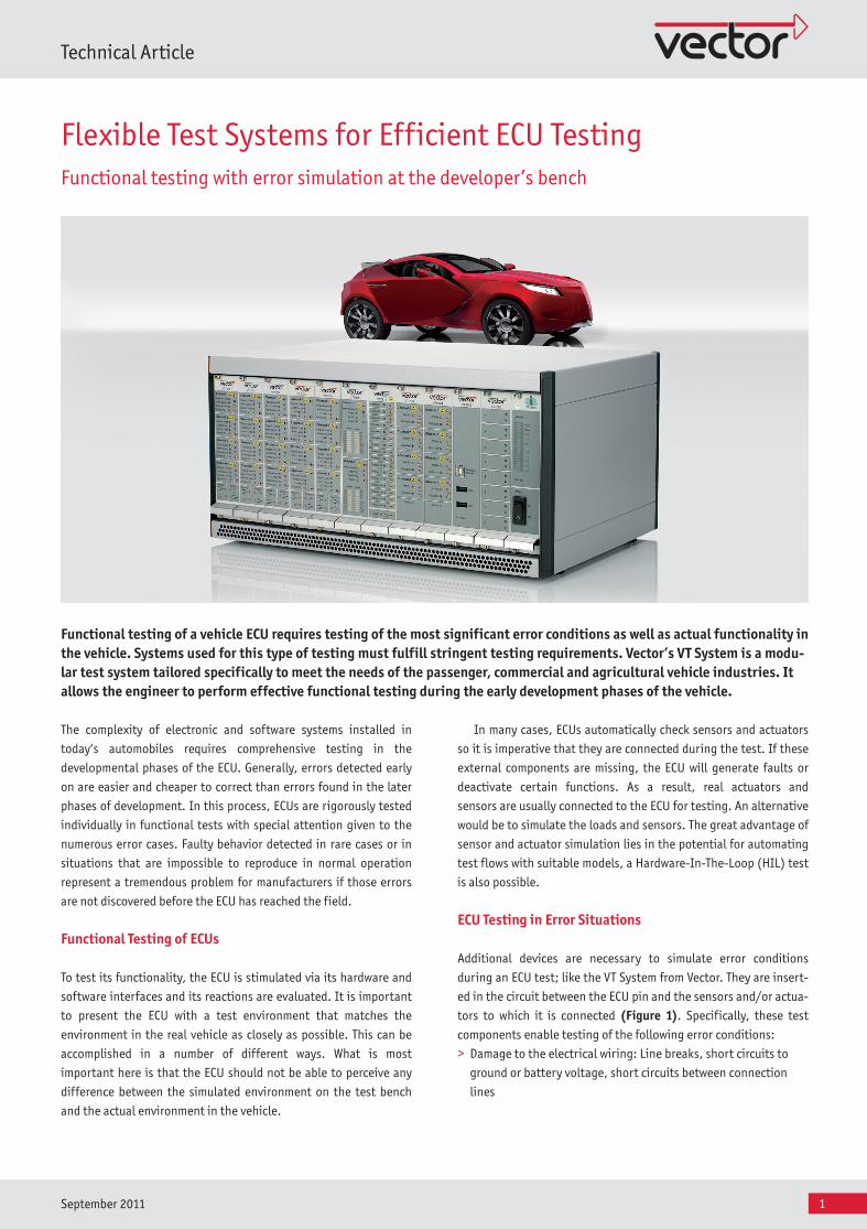
Functional testing of a vehicle ECU requires testing of the most significant error conditions as well as actual functionality in the vehicle. Systems used for this type of testing must fulfill stringent testing requirements. Vector’s VT System is a modu-lar test system tailored specifically to meet the needs of the passenger, commercial and agricultural vehicle industries. It allows the engineer to perform effective functional testing during the early development phases of the vehicle.
PND_VT_ElektronikPraxis_SH_201109_PressBook_released_EN.indd 1 28.07.2011 14:02:26
2
Technical Article
September 2011
> Sensors or actuators are damaged: Sensors do not output any
values, the values lie outside of the acceptable value range,
electrical properties of the components - such as internal resis-
tance or current consumption - do not conform to specification
> Incorrect input values, especially incorrect sensor data: From the
ECU’s perspective the sensor is working properly and measured
values lie within the allowable range. However, they are implau-
sible or contradict other sensor values.
The ECU must react in a defined way in these cases and generate
appropriate diagnostic entries. In turn, these entries can be
checked by the test system – in this case over the diagnostic
interface.
Compact Test Systems with the VT System
Systems based on CANoe and the VT System demonstrate that the
stringent requirements of high-performance test systems - with
regard to their interfaces and test hardware, test automation, user
control of software interfaces and options for rest-of-bus simula-
tion - can also be implemented in a compact test system for the
bench.
With CANoe, the user gets a mature and widely used tool for
analysis, simulation and test automation. Vector hardware inter-
faces provide reliable bus interfaces to CAN, LIN, FlexRay and
MOST. External measurement and test hardware from various
manufacturers may also be connected via GPIB, the serial port or
Ethernet.
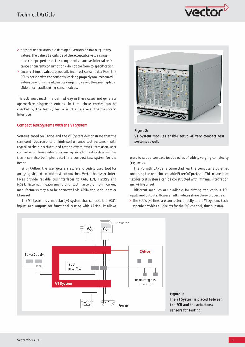
The VT System is a modular I/O system that controls the ECU’s
inputs and outputs for functional testing with CANoe. It allows
users to set up compact test benches of widely varying complexity
(Figure 2).
The PC with CANoe is connected via the computer’s Ethernet
port using the real-time capable EtherCAT protocol. This means that
flexible test systems can be constructed with minimal integration
and wiring effort.
Different modules are available for driving the various ECU
inputs and outputs. However, all modules share these properties:
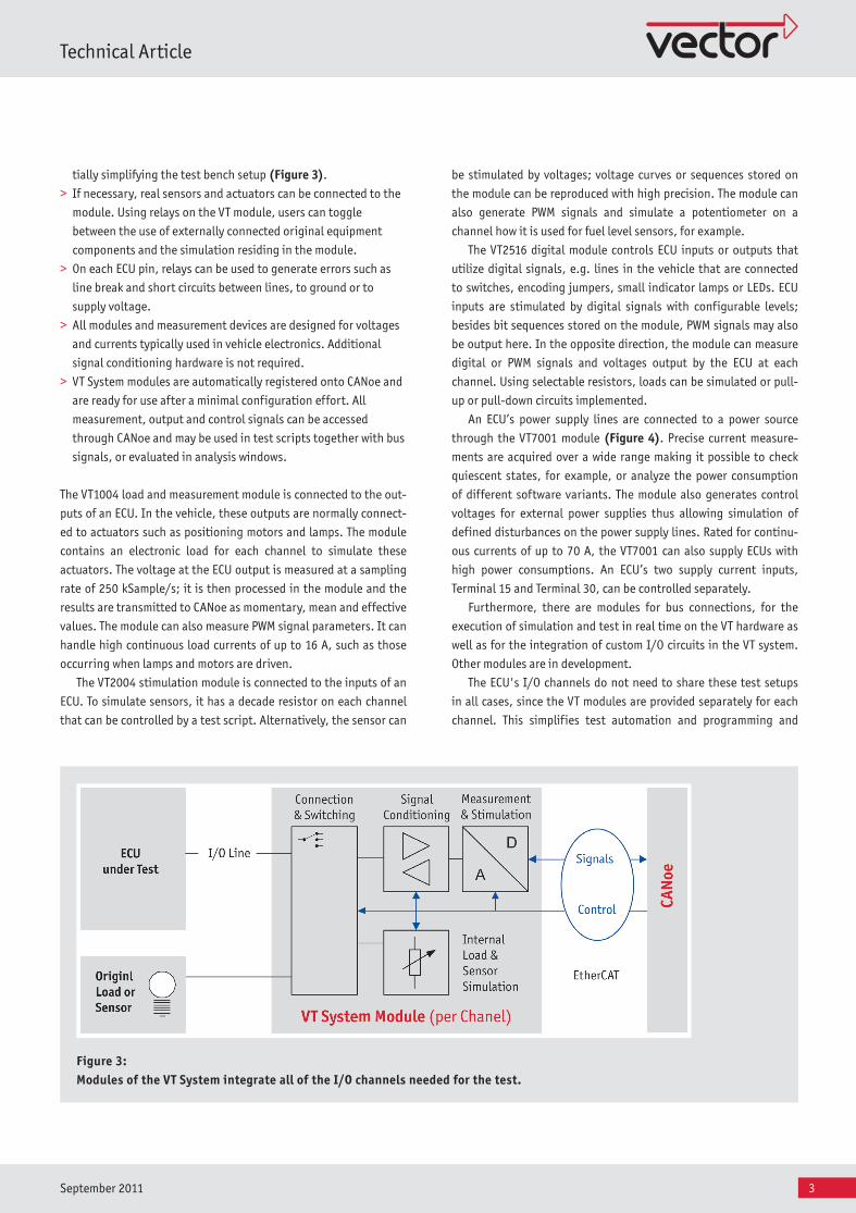
> The ECU’s I/O lines are connected directly to the VT System. Each
module provides all circuits for the I/O channel, thus substan-
Figure 1: The VT System is placed between the ECU and the actuators/ sensors for testing.
Figure 2: VT System modules enable setup of very compact test systems as well.
PND_VT_ElektronikPraxis_SH_201109_PressBook_released_EN.indd 2 28.07.2011 14:02:31
3
Technical Article
September 2011
be stimulated by voltages; voltage curves or sequences stored on
the module can be reproduced with high precision. The module can
also generate PWM signals and simulate a potentiometer on a
channel how it is used for fuel level sensors, for example.
The VT2516 digital module controls ECU inputs or outputs that
utilize digital signals, e.g. lines in the vehicle that are connected
to switches, encoding jumpers, small indicator lamps or LEDs. ECU
inputs are stimulated by digital signals with configurable levels;
besides bit sequences stored on the module, PWM signals may also
be output here. In the opposite direction, the module can measure
digital or PWM signals and voltages output by the ECU at each
channel. Using selectable resistors, loads can be simulated or pull-
up or pull-down circuits implemented.
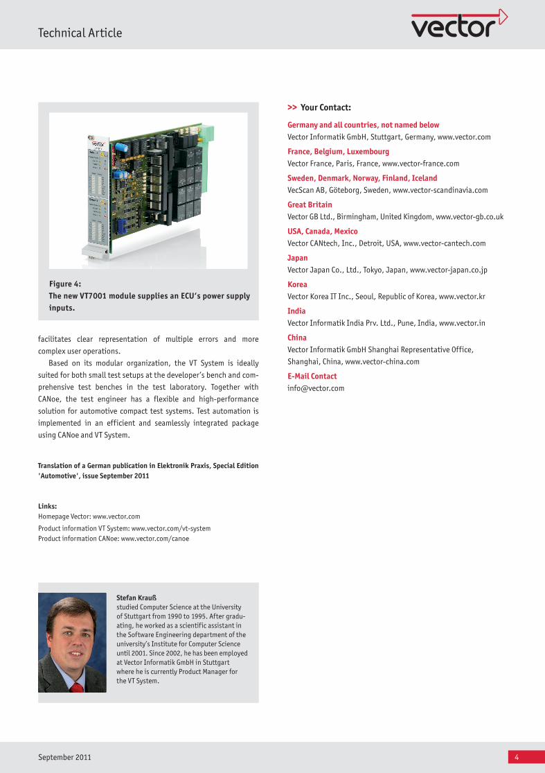
An ECU’s power supply lines are connected to a power source
through the VT7001 module (Figure 4). Precise current measure-
ments are acquired over a wide range making it possible to check
quiescent states, for example, or analyze the power consumption
of different software variants. The module also generates control
voltages for external power supplies thus allowing simulation of
defined disturbances on the power supply lines. Rated for continu-
ous currents of up to 70 A, the VT7001 can also supply ECUs with
high power consumptions. An ECU’s two supply current inputs,
Terminal 15 and Terminal 30, can be controlled separately.
Furthermore, there are modules for bus connections, for the
execution of simulation and test in real time on the VT hardware as
well as for the integration of custom I/O circuits in the VT system.
Other modules are in development.
The ECU's I/O channels do not need to share these test setups
in all cases, since the VT modules are provided separately for each
channel. This simplifies test automation and programming and
tially simplifying the test bench setup (Figure 3).
> If necessary, real sensors and actuators can be connected to the
module. Using relays on the VT module, users can toggle
between the use of externally connected original equipment
components and the simulation residing in the module.
> On each ECU pin, relays can be used to generate errors such as
line break and short circuits between lines, to ground or to
supply voltage.
> All modules and measurement devices are designed for voltages
and currents typically used in vehicle electronics. Additional
signal conditioning hardware is not required.
> VT System modules are automatically registered onto CANoe and
are ready for use after a minimal configuration effort. All
measurement, output and control signals can be accessed
through CANoe and may be used in test scripts together with bus
signals, or evaluated in analysis windows.
The VT1004 load and measurement module is connected to the out-
puts of an ECU. In the vehicle, these outputs are normally connect-
ed to actuators such as positioning motors and lamps. The module
contains an electronic load for each channel to simulate these
actuators. The voltage at the ECU output is measured at a sampling
rate of 250 kSample/s; it is then processed in the module and the
results are transmitted to CANoe as momentary, mean and effective
values. The module can also measure PWM signal parameters. It can
handle high continuous load currents of up to 16 A, such as those
occurring when lamps and motors are driven.
The VT2004 stimulation module is connected to the inputs of an
ECU. To simulate sensors, it has a decade resistor on each channel
that can be controlled by a test script. Alternatively, the sensor can
Figure 3: Modules of the VT System integrate all of the I/O channels needed for the test.
PND_VT_ElektronikPraxis_SH_201109_PressBook_released_EN.indd 3 28.07.2011 14:02:34
4
Technical Article
September 2011
facilitates clear representation of multiple errors and more
complex user operations.
Based on its modular organization, the VT System is ideally
suited for both small test setups at the developer’s bench and com-
prehensive test benches in the test laboratory. Together with
CANoe, the test engineer has a flexible and high-performance
solution for automotive compact test systems. Test automation is
implemented in an efficient and seamlessly integrated package
using CANoe and VT System.
Translation of a German publication in Elektronik Praxis, Special Edition 'Automotive', issue September 2011
Links:Homepage Vector: www.vector.com
Product information VT System: www.vector.com/vt-system Product information CANoe: www.vector.com/canoe
Figure 4: The new VT7001 module supplies an ECU‘s power supply inputs.
Stefan Krauß studied Computer Science at the University of Stuttgart from 1990 to 1995. After gradu-ating, he worked as a scientific assistant in the Software Engineering department of the university’s Institute for Computer Science until 2001. Since 2002, he has been employed at Vector Informatik GmbH in Stuttgart where he is currently Product Manager for the VT System.
>> Your Contact:
Germany and all countries, not named belowVector Informatik GmbH, Stuttgart, Germany, www.vector.com
France, Belgium, Luxembourg Vector France, Paris, France, www.vector-france.com
Sweden, Denmark, Norway, Finland, IcelandVecScan AB, Göteborg, Sweden, www.vector-scandinavia.com
Great BritainVector GB Ltd., Birmingham, United Kingdom, www.vector-gb.co.uk
USA, Canada, MexicoVector CANtech, Inc., Detroit, USA, www.vector-cantech.com
JapanVector Japan Co., Ltd., Tokyo, Japan, www.vector-japan.co.jp
KoreaVector Korea IT Inc., Seoul, Republic of Korea, www.vector.kr
IndiaVector Informatik India Prv. Ltd., Pune, India, www.vector.in
ChinaVector Informatik GmbH Shanghai Representative Office,
Shanghai, China, www.vector-china.com
E-Mail [email protected]
PND_VT_ElektronikPraxis_SH_201109_PressBook_released_EN.indd 4 28.07.2011 14:02:37