flexible self-charging supercapacitor based on graphene-ag...
TRANSCRIPT

Contents lists available at ScienceDirect
Nano Energy
journal homepage: www.elsevier.com/locate/nanoen
Full paper
Flexible self-charging supercapacitor based on graphene-Ag-3D graphenefoam electrodes
Libu Manjakkal, Carlos García Núñez, Wenting Dang, Ravinder Dahiya⁎
Bendable Electronics and Sensing Technologies (BEST) Group, School of Engineering, University of Glasgow, G12 8QQ, UK
A R T I C L E I N F O
Keywords:SupercapacitorGraphene foamSelf-powered systemsWearable systemspH sensorEnergy storage
A B S T R A C T
A flexible three-dimensional porous graphene foam-based supercapacitor (GFSC) is presented here for energystorage applications. With a novel layered structure of highly conductive electrodes (graphene-Ag conductiveepoxy–graphene foam), forming an electrochemical double layer, the GFSC exhibits excellent electrochemicaland supercapacitive performance. At a current density of 0.67mA cm−2, the GFSCs show excellent performancewith areal capacitance (38 mF cm−2) about three times higher than the values reported for flexible carbon-basedSCs. The observed energy and power densities (3.4 µW h cm−2 and 0.27mW cm−2 respectively) are better thanthe values reported for carbon-based SCs. Analyzed under static and dynamic bending conditions, the GFSCs arestable with up to 68% capacitance retention after 25000 charge–discharge cycles. The light-weight, cost-effec-tive fabrication and no self-heating make the GFSCs a promising alternative to conventional source of energy inthe broad power density ranging from few nW cm−2 to mW cm−2. In this regard, GFSC was integrated with aflexible photovoltaic cell resulting in a flexible self-charging power pack. This pack was successfully utilized topower continuously a wearable CuO nanorod based chemi-resistive pH sensor.
1. Introduction
Smart energy systems, comprising of efficient harvesting, storageand energy management components are critical for portable electronicapplications such as wearable systems [1], defence [2], transportation[3], fashion [4], etc. In particular, the advanced technologies that areexpected to be used for healthcare monitoring, such as e-skin [5],smart-coatings, tattoos like sensing patches [6,7] involve a largenumber of sensing devices with a high energy budget demand. Like-wise, other applications such as electric cars, aerial vehicles, roboticsand artificial prosthesis, which have higher estimated energy budgetsand on-board energy sources, will be benefited from the development ofhigh-performance energy systems. Supercapacitors (SCs) have recentlyemerged as a promising route to address the energy needs in aboveapplications [8–10].
To this end, the enhanced energy-conversion mechanisms throughvarious harvesting technologies based on photovoltaics (PVs) [11,12],piezoelectrics [13] and triboelectrics [14], have also been extensivelyinvestigated. Towards addressing the flexibility/stretchability require-ments of wearable systems [15,16], PV cells and triboelectric/piezo-electric nanogenerators [14], with suitable form factors have been in-vestigated [17,18]. While significant advances have been made inenergy harvesting field, there is also a need to develop a suitable
technology to store the excess of energy. Conventional Li-ion basedbatteries (LiB) (< 500W h kg−1) are not suitable for portable/wear-able systems because they are heavy, bulky and have poor performance.Further, the heat produced by commercially available batteries candamage the human skin [19] and thus limits their use in wearablesystems [3,5,20]. For these reasons, SCs have emerged as a promisingalternative to conventional Li-ion batteries [8–10]. SC have high energydensity (in the range of mWh cm−2) and power density (range ofW cm−2) (see Ragone's plot in Fig. S1 in Supplementary information),fast charging time (~ 1min), and high life cycle (> 106 cycles).Moreover, SCs present attractive features such as high flexibility, nothermal breakdown and environmental-friendly active/passive mate-rials. These features make SCs the excellent candidate for flexible andportable energy storing devices [21,22].
Based on the fundamental principle, SCs mainly work through ap-proaches of electrochemical double layer capacitor (EDLC) [22,23] andpseudo-capacitor (PC) [23,24]. By combining the EDLC and PC con-cepts, a third category, namely hybrid battery type supercapacitor(HSC) [25] has also emerged recently. Compared to PCs and HSCs,EDLCs have more stable performance (> 106 cycles), higher flexibilityand simpler fabrication procedures [22,23,26,27], which make EDLCssuitable for portable/wearable applications. In contrast to the LiBtechnology with high limitations in the energy storage capacity, the
https://doi.org/10.1016/j.nanoen.2018.06.072Received 10 March 2018; Received in revised form 14 June 2018; Accepted 20 June 2018
⁎ Corresponding author.E-mail address: [email protected] (R. Dahiya).
Nano Energy 51 (2018) 604–612
Available online 25 June 20182211-2855/ © 2018 The Author(s). Published by Elsevier Ltd. This is an open access article under the CC BY license (http://creativecommons.org/licenses/BY/4.0/).
T

features of SCs have demonstrated great scalability, i.e. SCs are ex-pected to power efficiently from low to high-power consumption de-vices. In this regard, the main characteristics of SC subjected to in-tensive investigations are the areal capacitance (CA), energy density(EA) and power density (PA). For example, 3D-graphene/graphite-paperbased SCs showing record values of CA (9mF cm−2),EA(1.24 µWh cm−2), and PA (25 µW cm−2) [28], it is still an energystorage technology limited to power flexible micro-/nano-devices withpower consumption in the range of mW cm−2 and nW cm−2 (Table 1).Here, we further enhanced the capability of carbon materials by de-monstrating promising results with EDLCs based on 3D graphene foam(GF) as electrodes. We take the advantage of the porosity in GF to in-crease the effective surface area of the electrode, and therefore, toobtain a faster and efficient electron transport through rapid the ionexchange mechanism [29,30]. A few GF-based SCs (GFSCs) reported inliterature have used composite of GF with metal oxides (MnO2, Co3O4)[29,31] or polymers (polypyrrole, PANi) as electrodes [32,33]. Gen-erally, these electrodes present good electrochemical performance, butthey have a low electrochemical stability under long-lasting charge-discharge cycles. This is either because of Faradaic redox reactions orthe mechanical degradation observed in metal oxide. In the case ofpolymer-based electrodes, SCs are relatively stable, but their low elec-trical conductivity still remains a bottleneck as it hinders the electrontransfer through the active material (e.g. GF with polyurethane (PU))[34].
In this work, we present for the first time an EDLC SC based on freestanding GF as electrode, with highly improves electron transfer fromelectrode to the active material. The new SC electrode structure re-ported here consists of a highly conductive graphene sheet (GS) as acurrent collector and GF as active material, both bonded with Ag con-ductive epoxy. The resulting SCs based on GS-Ag-GF layered electrodeswere characterized by cyclic voltammetry (CV), electrochemical im-pedance spectroscopy (EIS) analysis and galvanostatic charging dis-charging (GCD) method. In addition, the performance of developedGFSCs is compared with state-of-the-art SCs (Table 1). GFSCs were alsocharacterized under static and dynamic bending conditions as well astested for 25000 charging/discharging cycles. To demonstrate the ap-plicability in wearable systems, the GFSCs were integrated on a flexiblePV cell and a flexible fully self-charging power pack (FSPP) was ob-tained. The observed capacitance (38mF cm−2), energy and powerdensities (3.4 µW h cm−2 and 0.27mW cm−2 respectively) are bene-ficial for low power wearable sensors. New technologies are rapidlyevolving towards the development of self-powered systems with energyharvesters and storage devices on non-conventional flexible substrates.In this regard, triboelectric generator, piezoelectric generator and solarcells are considered as promising candidates [35]. However, the criticalchallenge is the variable power generation for energy harvesting suchas solar cells where sunlight may not available all the time. In this re-gard, a flexible energy storage device is necessary. A comparison be-tween recently reported self-powered systems for wearable applications
is given in Table S1 in the Supplementary information. The FSPP wassuccessfully used as a direct current (DC) source for the continuouspowering of a flexible chemi-resistive pH sensor [36], to demonstratethe promise the presented SCs hold for fully self-powered flexible sen-sors for health monitoring applications.
2. Experimental section
2.1. Fabrication of electrodes
The fabrication steps of GFSC electrodes are described in Fig. 1.Firstly, PU has been drop-casted on top of a 3×1.5 cm2
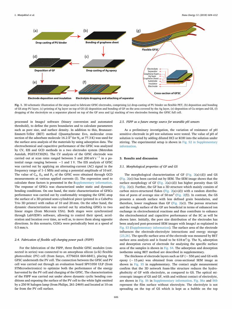
flexiblepolyethylene glycol terephthalate (PET) substrate (Fig. 1(a)). There-after, multi-layered GS consisting of 300 layers of stacked GS (fromGraphene Super Market, USA) was adhered on the top of the PU(Fig. 1(b)), having the role of charge collector. Resulting sample wasannealed at 80 °C for 2 h. After bonding to GS, Ag conductive epoxy(from RS components, 186–3600) was printed on the top of GS, par-tially covering an area of 3 cm2 (Fig. 1(c)). Then, 3 cm2 GF (fromGraphene Super Market, USA) has been deposited atop the area coveredby the Ag epoxy and cured at room temperature for 1 h to ensure theproper bonding of GS and GF (Fig. 1(d)). The Ag conductive epoxyprovides excellent adhesion between GS and GF. The high conductivityof the epoxy reduces the contact resistance between the electrodes asshown later. As connection pad, a Cu strip was connected to externalterminals of the SC (Fig. 1(e)), using a protective PU layer to ensure theimpermeable encapsulation of those areas that will be in contact withthe electrolyte. Thereafter, the electrolyte (H3PO4) were dropped on topof the GF area, followed by the deposition of a polyester/cellulose blendseparator (Techni Cloth, TX 612) on top of the wet area (Fig. 1(f)). Theseparator is meant to act as an ion permeable membrane and absorbentelectrolyte for keeping wettability. The complete fabrication of the SCcomprises the fabrication of two electrodes (Fig. 1(a)-(e)), and finally,their stacking as schematically illustrated in Fig. 1(g). To protect theGFSC from electrolyte leakage, the device was packed and encapsulatedby using Kapton tape and then by polymer film.
2.2. Fabrication of chemi-resistive pH sensor
CuO nanostructured material was prepared by hydrothermalsynthesis method and the sensitive electrode was fabricated by screen-printing method on a flexible PET substrate. A chemi-resistive CuOnano-rod based flexible pH sensor on PET substrate was fabricated byscreen-printing method, as thoroughly described elsewhere [36].
2.3. Characterization of GFSC electrodes
Morphological characterization of as-fabricated GF electrodes wascarried out by means of scanning electron microscope (SEM, SU8240BRUKER, at 15 kV and WD of 8mm). The SEM images were post
Table 1Comparison of the areal capacitance and corresponding energy and power densities of EDLCs based SCs.
Material Electrolyte Areal Capacitance Energy density Power density Ref
3D-graphene/ graphite-paper (full cell) PVA-H2SO4 9mF cm−2 at 0.05mA 1.24 µWh cm−2 0.0245mW cm−2 [28]Ultrathin Planar CVD Graphene film H3PO4 0.394mF cm−2 2.8 nW h cm−2 2 µW cm−2 [37]Wrinkled graphene film H2SO4-PVA 5.33 μF cm−2 0.27 nWh cm−2 11.77 μWcm−2 [38]Graphene thin film PVA/H3PO4 3.7 mF cm−2 0.235 µWh cm−2 0.106mW cm−2 [39]Electrochemically activated rGO film PVA/H3PO4 11.15 at 1 mA cm−2 – – [40]
15.38 at 0.1 mA cm−2
Onion-like carbon Et4NBF4/propylene carbonate 1.7 at 1 V s−1 1× 10⁻² W h cm−3 1 kW cm−3 [41]Nitrogen-doped rGO (flexible) PVA/H3PO4 3.4 at 20 μA cm−2 3.0× 10⁻⁴ W h cm−3 0.2W cm−3 [43]rGO/CNT 3M KCl 6.1 at 0.01 V s−1 0.7mWh cm− 3 77W cm− 3 [44]rGO PVA/H2SO4 0.95 at 0.43mA cm−2 ….. ….. [45]Laser-induced Graphene H2SO4/PVA 9 at 0.02mA cm−2 [46]Graphene Foam based SC H3PO4 38mF cm−2 at 0.67mA cm−2 3.4 µW h cm−2 0.27mW cm−2 This work
L. Manjakkal et al. Nano Energy 51 (2018) 604–612
605
processed in ImageJ software (binary conversion and automatedthreshold), to define the pores boundaries and to calculate parameterssuch as pore size, and surface density. In addition to this, Brunauer-Emmett-Teller (BET) method (Quantachrome Evo, molecular crosssection of the adsorbate molecule 16.2 Å2 for N2 at 77.3 K) was used forthe surface area analysis of the materials by using adsorption data. Theelectrochemical and capacitive performance of the GFSC was analyzedby CV, EIS and GCD methods in a two electrodes system (MetrohmAutolab, PGSTAT302N). The CV analysis of the GFSC electrode wascarried out at scan rates ranged between 5 and 200mV s−1 in a po-tential range ranging between −1 and 1 V. The EIS analysis of GFSCwas carried out by applying an alternating-current (AC) signal in thefrequency range of 1–1MHz and using a potential amplitude of 10mV.The value of CA, EA and PA of the GFSC were obtained through GCDmeasurements at various applied currents (I). The expression used tocalculate these factors is presented in the Supplementary information.The response of GFSCs was characterized under static and dynamicbending conditions. On one hand, the static characterization of GFSCsperformance was carried out by conformably wrapping the GFSC atopthe surface of a 3D-printed semi-cylindrical piece (printed in a CubeProTrio 3D printer) with radius of 10 and 20mm. On the other hand, thedynamic characterization was carried out by attaching GFSCs to twolinear stages (from Micronix USA). Both stages were synchronizedthrough LabVIEW's software, allowing to control their speed, accel-eration and location over time, as well as, to move them along oppositedirections. In this scenario, CGSCs were periodically bent at a speed of0.5 mm/s.
2.4. Fabrication of flexible self-charging power pack (FSPP)
For the fabrication of the FSPP, three flexible GFSC modules (con-nected in series) was connected to an amorphous silicon (a-Si) flexiblephotovoltaic (PV) cell (from Sanyo, AT7665A 664-6841), placing theGFSC underneath the PV cell. The connection between the GFSC and PVcell was carried out through an evaluation board SPV1050 ULP (fromSTMicroelectronics) to optimize both the performance of the energyharvested by the PV cell and charging of the GFSC. The characterizationof the FSPP was carried out under above dynamic cyclic bending con-ditions and exposing the surface of the PV cell to the white light emittedby a 250W halogen lamp (from Philips, 261-2469) and located at 10 cmfar from the PV cell surface.
2.5. FSPP as a future energy source for wearable pH sensors
As a preliminary investigation, the variation of resistance of pHsensitive electrode in pH test solutions were tested. The value of pH ofsolution is varied by adding diluted HCl or KOH into the solution understirring. The experimental setup is shown in Fig. S2 in Supplementaryinformation.
3. Results and discussion
3.1. Morphological properties of GF and GS
The morphological characterization of GF (Fig. 2(a)-(d)) and GS(Fig. 2(e)) has been carried out by SEM. The SEM image shows that thesurface morphology of GF (Fig. 2(a)-(d)) has higher porosity than GS(Fig. 2(e)). Further, the GF has a 3D structure which mainly consists ofcarbon micro-structured flakes (Fig. 2(a)-(d)) with a random distribu-tion of pores of average size of 50 nm2 (Fig. 2(f)). In contrast, the GSpresents a smooth surface with less defined grain boundaries, andtherefore, lower roughness than GF (Fig. 2(e)). The porous structureand the rough surface of the GF are beneficial in terms of enhanced ionexchange in electrochemical reactions and thus contribute to enhancethe electrochemical and capacitive performance of the SC as will beshown later. Initially, the pore size distribution of the electrodes hasbeen analyzed post-processed SEM images with ImageJ as explained inFig. S3 (Supplementary information). The surface area of the electrodeinfluences the electrode-electrolyte interactions and energy storage[23,26]. The specific surface area of the electrode was measured by BETsurface area analysis and is found to be 618m2/g. The N2 adsorptionand desorption curves of electrode for analysing the specific surfacearea of the samples is shown in Fig. S4. The adsorption and desorptionisotherms using BET method are described in supplementary.
The thickness of electrode layers such as GF (~ 550 µm) and GS withepoxy (~ 15 µm) was obtained from cross-sectional SEM image asshown in Fig. S5 in supplementary. The contact angle measurementconfirm that the 3D network foam-like structure reduces the hydro-phobicity of GF with electrolyte, as compared to GS. The optical mi-croscopic images of GS and GF, with and without contact of electrolyte,are shown in Fig. S6 in Supplementary information. Fig. S6a and S6brepresent the film surface without electrolyte. The electrolyte is notspreading on the top of GS which is kept as a bubble on the top
Fig. 1. 3D schematic illustration of the steps used to fabricate GFSC electrodes, comprising (a) drop-casting of PU binder on flexible PET, (b) deposition and bondingof GS atop PU layer, (c) printing of Ag layer on top of GS (d) deposition and bonding of GF on the area covered by the Ag layer, (e) deposition of Cu stripes and GS, (f)dropping of the electrolyte on a separator placed on top of the GF area and (g) stacking of two electrodes forming the GFSC full cell.
L. Manjakkal et al. Nano Energy 51 (2018) 604–612
606

presented in Fig S6c. The observed contact angle for GS is around 70°(Fig. S7 in supplementary) and hence it shows hydrophobic naturewhile reacting with electrolyte. However, due to the porous 3D net-works GF have a very good interaction with electrolytes as shown inFig. S6d. The observed contact angle for the GF with electrolyte is al-most 0° as shown in Fig. S7. The hydrophilic nature of GF enhances theelectrochemical performance for energy storage by increasing the ionicexchange at electrode-electrolyte interface.
3.2. Electro-chemical properties of GFSC electrodes
The electro-chemical and electro-capacitive performance of GFSCelectrodes have been investigated in the two-electrode system usingH3PO4 as electrolyte. According to the general mechanism governingEDLC based SCs [23,37,38], positive (H+) and negative (PO4
3-, HPO42-
and H2PO4-) [39] ions from H3PO4 electrolyte are absorbed on thecathode and anode electrodes, respectively, during the charging step(Fig. 3(a)). The absorption of electrolyte positive and negative ions intoSC electrodes by electrostatically or non-Faradaic reactions results inelectrical double layer (edl). In GFSC electrodes, the edl occurs along thehigh surface area of the porous GF layer. The high surface area ofporous GF and less hydrophobicity (shown in Fig. 2(f) and 2(i)) en-hance the ion absorption (Fig. 3(a)) on the electrode surface and im-prove the charge storing capacity. During discharging, ions desorb fromelectrode surface and move to the electrolyte due to the absence of netelectrical force. The good wettability of the H3PO4 electrolyte by usingcellulose separator will facilitate the mobility of ions during both ionabsorption and desorption mechanism into the pores of the GF elec-trodes. This will further enhance the capacitive performance of theproposed device and is evaluated in following section.
The CV and EIS analysis of the device were carried out to demon-strate above mechanisms and to study the electrochemical properties ofGFSC electrode (Fig. 3). CV curves of a GFSC cell (Fig. 1(g)), measuredat scan rates ranged between 5 and 200mV s−1 are presented in Fig. 3band Fig. S7 in Supplementary information. From these figures, it can beobserved that CV presents a cyclic shape independently on the scanrate. However, the shape of the CV is strongly influenced by the scanrate, especially in the range of 5–50mV s−1, where the slope of the CVcurve and maximum current levels exhibit smaller value than thoseobtained at higher scan rates in the range of 50–200mV s−1 (the ex-tended CV analysis shown in Fig. S8 in Supplementary). This result is ingood agreement with the electrical current measured at 1 V as a
function of the scan rate (Fig. 3(c)), where the resulting current densityincreases with the scan rate. Above results are important to understandthe behavior of a GFSC as energy storing device, directly varyingproperties such as acquired current density, operating voltages, etc. Inparticular, the increase of the maximum current levels up to 7.4mA(0.5 < V < 1V) obtained at a high scanning rates of 200mV s−1
(Fig. 3b and Fig. 3c), would indicate a predominant diffusion me-chanism governing the reaction of ions from the electrolyte to the GFSCelectrode surface in addition to the general absorption mechanism.Moreover, the use of low scanning rates (5–20mV s−1) allows the ob-servation of a redox peak at around 0.2 V with a maximum current of6.3 mA (Fig. S8 in supplementary), which is due to the reaction at theinterface between Ag and GF layers in addition to non-Faradaic reactionbetween the GFSC and electrolyte. This result demonstrates that theconductive Ag layer for bonding also contributes to the electrochemicalreaction of fabricated GFSCs at low scanning rate.
EIS analysis has been carried out to further evaluate properties ofGFSC electrodes, including ion exchange, charge transport and capa-citive performance at electrode/electrolyte interface (Fig. 3(d)-(f)).Nyquist's plot presented in Fig. 3(d), shows a linear trend at lowerfrequencies (1 Hz–10mHz), i.e. 40 < Zreal < 85Ω, and a slope of 46°,reflecting the ideal capacitive nature of GFSC electrodes, and con-firming the diffusion mechanism of ions through the electrode surfacemainly favoured by the porosity of the GF structure (Fig. 2(d)). In thisparticular frequency range, the variation of resistance was observedbetween 25 and 85Ω, which are extremely low values for ionic ex-change and reveal a high and rapid ion interaction of GF active materialwith the electrolyte. This result partially explains the origin of thesignificant enhancement obtained in the electrochemical performanceof the fabricated GFSCs. In the high frequencies region the resistance isbelow< 25Ω and an inflection point is observed at ~ 3Ω in the Ny-quist's plot (Fig. 3d). The concave downwards trend observed below 3Ω(inset of Fig. 3(d)) is the characteristic curve of a charge-transfer pro-cess whose resistance is defined as charge transfer resistance (Rct). Thevalue of Rct can be calculated from the radius of a circle fitting theconcave downwards trend observed in Fig. 3(d). The calculations reveala low Rct (< 1Ω), which is influenced by the Ag layer. The lower valueof Rct reveals that the contact resistance between the Ag conductiveepoxy and GS is very low and is beneficial for the energy storage ap-plication. The non-zero intersection at high frequencies is due to thesolution resistance (Rs) and one additional ohmic resistance from theactive electrode material. Rs is estimated to be around 2.3Ω (inset of
Fig. 2. SEM image of (a-d) GF and (e) GS at different magnification and (f) porosity of GF obtained from (d).
L. Manjakkal et al. Nano Energy 51 (2018) 604–612
607
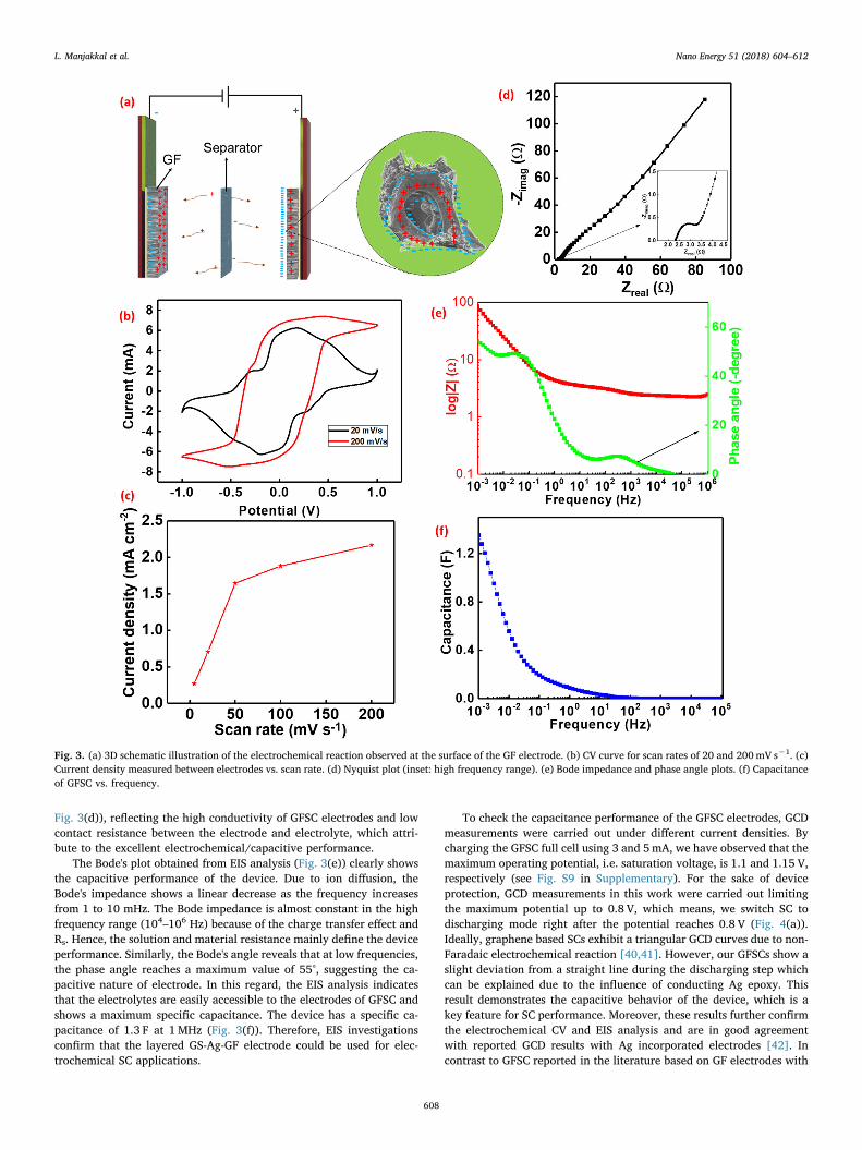
Fig. 3(d)), reflecting the high conductivity of GFSC electrodes and lowcontact resistance between the electrode and electrolyte, which attri-bute to the excellent electrochemical/capacitive performance.
The Bode's plot obtained from EIS analysis (Fig. 3(e)) clearly showsthe capacitive performance of the device. Due to ion diffusion, theBode's impedance shows a linear decrease as the frequency increasesfrom 1 to 10 mHz. The Bode impedance is almost constant in the highfrequency range (104–106 Hz) because of the charge transfer effect andRs. Hence, the solution and material resistance mainly define the deviceperformance. Similarly, the Bode's angle reveals that at low frequencies,the phase angle reaches a maximum value of 55°, suggesting the ca-pacitive nature of electrode. In this regard, the EIS analysis indicatesthat the electrolytes are easily accessible to the electrodes of GFSC andshows a maximum specific capacitance. The device has a specific ca-pacitance of 1.3 F at 1MHz (Fig. 3(f)). Therefore, EIS investigationsconfirm that the layered GS-Ag-GF electrode could be used for elec-trochemical SC applications.
To check the capacitance performance of the GFSC electrodes, GCDmeasurements were carried out under different current densities. Bycharging the GFSC full cell using 3 and 5mA, we have observed that themaximum operating potential, i.e. saturation voltage, is 1.1 and 1.15 V,respectively (see Fig. S9 in Supplementary). For the sake of deviceprotection, GCD measurements in this work were carried out limitingthe maximum potential up to 0.8 V, which means, we switch SC todischarging mode right after the potential reaches 0.8 V (Fig. 4(a)).Ideally, graphene based SCs exhibit a triangular GCD curves due to non-Faradaic electrochemical reaction [40,41]. However, our GFSCs show aslight deviation from a straight line during the discharging step whichcan be explained due to the influence of conducting Ag epoxy. Thisresult demonstrates the capacitive behavior of the device, which is akey feature for SC performance. Moreover, these results further confirmthe electrochemical CV and EIS analysis and are in good agreementwith reported GCD results with Ag incorporated electrodes [42]. Incontrast to GFSC reported in the literature based on GF electrodes with
Fig. 3. (a) 3D schematic illustration of the electrochemical reaction observed at the surface of the GF electrode. (b) CV curve for scan rates of 20 and 200mV s−1. (c)Current density measured between electrodes vs. scan rate. (d) Nyquist plot (inset: high frequency range). (e) Bode impedance and phase angle plots. (f) Capacitanceof GFSC vs. frequency.
L. Manjakkal et al. Nano Energy 51 (2018) 604–612
608
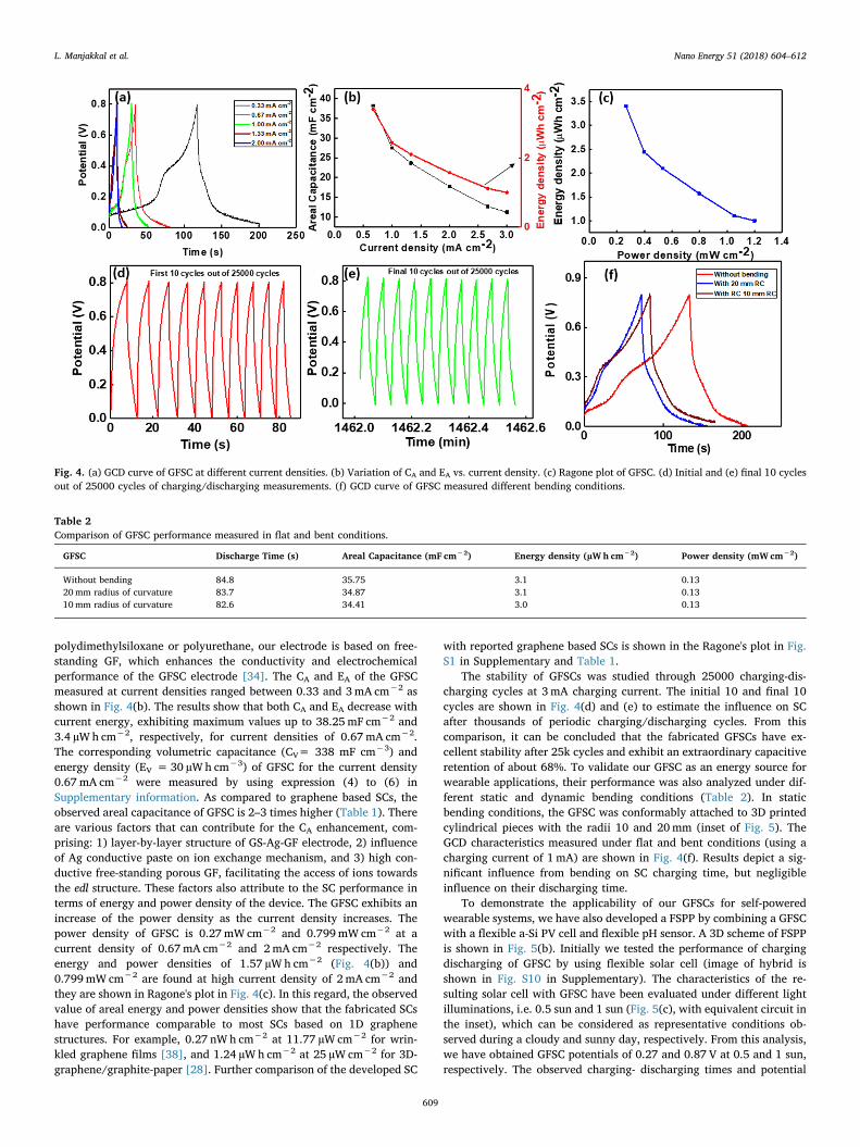
polydimethylsiloxane or polyurethane, our electrode is based on free-standing GF, which enhances the conductivity and electrochemicalperformance of the GFSC electrode [34]. The CA and EA of the GFSCmeasured at current densities ranged between 0.33 and 3mA cm−2 asshown in Fig. 4(b). The results show that both CA and EA decrease withcurrent energy, exhibiting maximum values up to 38.25mF cm−2 and3.4 µWh cm−2, respectively, for current densities of 0.67mA cm−2.The corresponding volumetric capacitance (CV= 338 mF cm−3) andenergy density (EV = 30 µWh cm−3) of GFSC for the current density0.67mA cm−2 were measured by using expression (4) to (6) inSupplementary information. As compared to graphene based SCs, theobserved areal capacitance of GFSC is 2–3 times higher (Table 1). Thereare various factors that can contribute for the CA enhancement, com-prising: 1) layer-by-layer structure of GS-Ag-GF electrode, 2) influenceof Ag conductive paste on ion exchange mechanism, and 3) high con-ductive free-standing porous GF, facilitating the access of ions towardsthe edl structure. These factors also attribute to the SC performance interms of energy and power density of the device. The GFSC exhibits anincrease of the power density as the current density increases. Thepower density of GFSC is 0.27mW cm−2 and 0.799mW cm−2 at acurrent density of 0.67mA cm−2 and 2mA cm−2 respectively. Theenergy and power densities of 1.57 µW h cm−2 (Fig. 4(b)) and0.799mW cm−2 are found at high current density of 2mA cm−2 andthey are shown in Ragone's plot in Fig. 4(c). In this regard, the observedvalue of areal energy and power densities show that the fabricated SCshave performance comparable to most SCs based on 1D graphenestructures. For example, 0.27 nWh cm−2 at 11.77 µW cm−2 for wrin-kled graphene films [38], and 1.24 µW h cm−2 at 25 µW cm−2 for 3D-graphene/graphite-paper [28]. Further comparison of the developed SC
with reported graphene based SCs is shown in the Ragone's plot in Fig.S1 in Supplementary and Table 1.
The stability of GFSCs was studied through 25000 charging-dis-charging cycles at 3mA charging current. The initial 10 and final 10cycles are shown in Fig. 4(d) and (e) to estimate the influence on SCafter thousands of periodic charging/discharging cycles. From thiscomparison, it can be concluded that the fabricated GFSCs have ex-cellent stability after 25k cycles and exhibit an extraordinary capacitiveretention of about 68%. To validate our GFSC as an energy source forwearable applications, their performance was also analyzed under dif-ferent static and dynamic bending conditions (Table 2). In staticbending conditions, the GFSC was conformably attached to 3D printedcylindrical pieces with the radii 10 and 20mm (inset of Fig. 5). TheGCD characteristics measured under flat and bent conditions (using acharging current of 1mA) are shown in Fig. 4(f). Results depict a sig-nificant influence from bending on SC charging time, but negligibleinfluence on their discharging time.
To demonstrate the applicability of our GFSCs for self-poweredwearable systems, we have also developed a FSPP by combining a GFSCwith a flexible a-Si PV cell and flexible pH sensor. A 3D scheme of FSPPis shown in Fig. 5(b). Initially we tested the performance of chargingdischarging of GFSC by using flexible solar cell (image of hybrid isshown in Fig. S10 in Supplementary). The characteristics of the re-sulting solar cell with GFSC have been evaluated under different lightilluminations, i.e. 0.5 sun and 1 sun (Fig. 5(c), with equivalent circuit inthe inset), which can be considered as representative conditions ob-served during a cloudy and sunny day, respectively. From this analysis,we have obtained GFSC potentials of 0.27 and 0.87 V at 0.5 and 1 sun,respectively. The observed charging- discharging times and potential
Fig. 4. (a) GCD curve of GFSC at different current densities. (b) Variation of CA and EA vs. current density. (c) Ragone plot of GFSC. (d) Initial and (e) final 10 cyclesout of 25000 cycles of charging/discharging measurements. (f) GCD curve of GFSC measured different bending conditions.
Table 2Comparison of GFSC performance measured in flat and bent conditions.
GFSC Discharge Time (s) Areal Capacitance (mF cm−2) Energy density (µWh cm−2) Power density (mW cm−2)
Without bending 84.8 35.75 3.1 0.1320mm radius of curvature 83.7 34.87 3.1 0.1310mm radius of curvature 82.6 34.41 3.0 0.13
L. Manjakkal et al. Nano Energy 51 (2018) 604–612
609

with the light intensity are shown as Table in the inset of Fig. 5(c). Itwas found that at high potential the device discharge faster (37 s for 1sun) than at low potential, where the discharging time was very slow(1044 s for 1 sun). Thus, the FSPP is suitable for low operating potentialin wearable devices. FSPP has also been characterized under dynamicbending conditions (Fig. 5(d)) with bending at a speed of 0.5 mm/s. Aminor shift in the potential window (~ 0.08 V) with and withoutbending was observed. The shift in potential window during bendingmay due to change of the surface area of the electrode. However, thedevice recovery was very fast after bending as shown in Fig. 5(d).
The FSPP has been used as DC source (through a load resistance (RL)of 5 kΩ) to power continuously a flexible pH sensor. For this purpose,we have used a pH sensor based on nanostructured CuO nanorods,whose fabrication method and characteristics have been thoroughlydescribed elsewhere [36]. To ensure the operation of aforementionedpH sensor, a DC power is supplied across the conducting electrode ofthe sensor using the FSPP (Fig. 5(e)). Once the FSPP is connected to thepH sensor, we measured the resistance variation of flexible pH sensorbased on CuO nanorods (Fig. 5(e)) as a function of different pH solu-tions. Prior to the pH sensor characterization, the GFSC in the FSPP isfully charged through PV cell under 1 sun illumination (3.8 mW cm−2,Isc = 26.6 mA, Voc = 4.7 V), using a voltage divider to limit the char-ging current and voltage up to 0.5mA and 0.8 V, respectively. In thisscenario, the GFSC can supply a potential of 0.8 V to the pH sensor evenif we need< 250mV. Since the power harvested by the PV cell isaround 3.8 mW cm−2, the power density of the GFSC is 0.27mW cm−2,and the power consumption of the pH sensor is in the range of nWcm−2, the connection of the FSPP to the pH sensor guarantees a rapidcharging of the GFSC by the PV cell, and a slower discharging than thecharging times. These conditions show a continuous operation of a pHsensor without using an external battery (see inset of Fig. 5(f)). Thisalso demonstrates that our GFSC based FSPP is a viable technology forself-powered systems. From that characterization, one can concludethat the output voltage across the sensor is measured as a function ofthe pH value of the solution under test (Fig. S11 in supplementary). We
have also found that by increasing the pH value of the solution towardsbasic region the resistance of the pH sensor value increases (Fig. 5f). Inan acidic region of the solution, the ions absorbed on the sensitiveelectrode are mainly hydroxonium ions (H3O+), whereas this is done byhydroxyl ions (OH-) in the basic solution. The slight drift in resistance inpH measurement is due to the lack of stability of pH solution whilestirring.
After finishing the measurement, we observed a negligible reductionof GFSC potential of 10mV, which confirms the rapid charging me-chanism carried out by the PV cell alternatively to the slow dischargingof the SC from the pH sensor. In good agreement with our previousobservations shown in Fig. S12 in Supplementary, we found that theGFSC took around 115 s to drop a voltage of only 15mV, which makethe FSPP suitable to power a pH sensor with a fast response in the rangeof tens of seconds. From the pH sensing performance, we observed thatthe pH sensor shows very fast response. The response time of the sensoris less than 5 s from pH 6.38 to pH 4 (from Fig. 5(e)) and from pH 5 topH 5.8 it is nearly 12 s. This fast response of sensor further highlightsthe benefits of self-powered system.
With the high energy density and stability of the GFSC based FSPPcombined with the low-power consumption of the pH sensor, we havesuccessfully characterized pH sensor with and without sunlight (Fig. 6).The current measured through the SC (ISC) and the pH sensor (IpH)present uniform characteristics with PV cell on (t < 5min) and off(t > 5min). Such a platform can be further extended towards a 24 hself-powering systems consisting of multiple nano-/micro-devices,possibly transmitting the data to smartphone, or for applications suchas fully-energy-autonomous e-skin for prosthetics and robotics [5].
4. Conclusion
This work presents a novel GFSC with layer-by-layer structureconsisting of graphene sheet-Ag-graphene foam as high energy densityelectrode. Fabricated GFSC exhibited an areal capacitance of38mF cm−2, energy density of 3.4 µW h cm−2 and power density of
Fig. 5. (a) GCD curve of flat and bent GFSC under bending radius of 10mm and 20mm. (b) 3D schema of FSPP (flexible PV cell, GFSC and pH sensor) (c) charging/discharging of GFSC by using flexible PV cell exposed to different light intensities (d) performance of GFSC and PV cell under dynamic bending conditions (e)Schematic of chemi-resistive pH sensor with an image of nanostructured CuO (f) chemi-resistive based pH sensor performance using GFSC as a voltage source.
L. Manjakkal et al. Nano Energy 51 (2018) 604–612
610

0.27mW cm−2 at current density of 0.67mA cm−2. The extensivecharacterization of GFSCs under static and dynamic bending conditionsshows that they have excellent electrochemical and supercapacitiveperformance, which is due to the benefit from Ag conductive epoxy, thehigh surface area in the porous structure of electrodes and the highlyconductivity of free-standing 3D graphene foam. The excellent life cycleof presented GFSCs, with capacitance retention of 68% after 25000charge/discharge cycles, shows their potential for use in several ap-plications and the suitability for manufacturing. In this regard, GFSCwas integrated with a flexible PV cell, resulting in a FSPP capable toproduce a continuous DC power. The applicability of the GFSC basedFSPP was demonstrated by powering continuously a nanostructuredCuO based pH sensor. This technology has demonstrated promisingadvances towards the successful development of fully self-poweredsystem in areas such as multi-sensing e-skin for robots and humanhealthcare monitoring.
Acknowledgements
This work was partially supported by EPSRC EngineeringFellowship for Growth – Printable Tactile Skin (EP/M002527/1) andthe Scottish Funding Council through SFC-GCRF (SFC/AN/15/2016)project on Energy Autonomous Bio-Sensor Patch suited for AffordableSelf-Health Monitoring. Authors are thankful to the staff at James WattNanofabrication Centre (JWNC) and Electronics Systems Design Centre(ESDC) at University of Glasgow for the support related to fabricationand characterization.
Appendix A. Supporting information
Supplementary data associated with this article can be found in theonline version at doi:10.1016/j.nanoen.2018.06.072.
References
[1] G. Lee, S.-K. Kang, S.M. Won, P. Gutruf, Y.R. Jeong, J. Koo, S.-S. Lee, J.A. Rogers,J.S. Ha, Fully biodegradable microsupercapacitor for power storage in transientelectronics, Adv. Energy Mater. 7 (2017) 1700157.
[2] Z. Yuan, X. Du, N. Li, Y. Yin, R. Cao, X. Zhang, S. Zhao, H. Niu, T. Jiang, W. Xu,Z.L. Wang, C. Li, Triboelectric-based transparent secret code, Adv. Sci. (2018)1700881.
[3] Y. Han, Q. Li, T. Wang, W. Chen, L. Ma, Multisource coordination energy man-agement strategy based on SOC consensus for a PEMFC–battery–supercapacitorhybrid tramway, IEEE Trans. Veh. Technol. 67 (2018) 296–305.
[4] M. Hu, T. Hu, R. Cheng, J. Yang, C. Cui, C. Zhang, X. Wang, MXene-coated silk-derived carbon cloth toward flexible electrode for supercapacitor application, J.Energy Chem. 27 (2018) 161–166.
[5] C. García Núñez, W.T. Navaraj, E.O. Polat, R. Dahiya, Energy-autonomous, flexible,and transparent tactile skin, Adv. Funct. Mater. 27 (2017) 1606287.
[6] J. Bandodkar, J. Wang, Non-invasive wearable electrochemical sensors: a review,Trends Biotechnol. 32 (2014) 363–371.
[7] W. Dang, L. Manjakkal, W.T. Navaraj, L. Lorenzelli, V. Vinciguerra, R. Dahiya,Stretchable wireless system for sweat pH monitoring, Biosens. Bioelectron. 107(2018) 192–202.
[8] D.P. Dubal, N.R. Chodankar, D.H. Kim, P. Gomez-Romero, Towards flexible solid-state supercapacitors for smart and wearable electronics, Chem. Soc. Rev. 47 (2018)2065–2129.
[9] B. Song, L. Li, Z. Lin, Z.K. Wu, K.S. Moon, K. S, C.P. Wong, Water-dispersible gra-phene/polyaniline composites for flexible micro-supercapacitors with high energydensities, Nano Energy 16 (2015) 470–478.
[10] B. Song, K.S. Moon, C.P. Wong, Recent developments in design and fabrication ofgraphene-based interdigital micro-supercapacitors for miniaturized energy storagedevices, IEEE Trans. Compon. Packag. Manuf. Technol. 6 (2016) 1752–1765.
[11] E. Ostfeld, A.C. Arias, Flexible photovoltaic power systems: integration opportu-nities, challenges and advances, Flex. Print. Electron. 2 (2017) 013001.
[12] J. Jaksik, H.J. Moore, T. Trad, O.I. Okoli, M.J. Uddin, Nanostructured functionalmaterials for advanced three-dimensional (3D) solar cells, Sol. Energy Mater. Sol.Cells 167 (2017) 121–132.
[13] Y.B. Lee, J.K. Han, S. Noothongkaew, S.K. Kim, W. Song, S. Myung, S.S. Lee, J. Lim,S.D. Bu, K.-S. An, Toward arbitrary-direction energy harvesting through flexiblepiezoelectric nanogenerators using perovskite PbTiO3 nanotube arrays, Adv. Mater.29 (2017) 1604500.
[14] Z. Lin, J. Chen, X. Li, Z. Zhou, K. Meng, W. Wei, J. Yang, Z.L. Wang, Triboelectricnanogenerator enabled body sensor Network for self-powered human heart-ratemonitoring, ACS Nano 11 (2017) 8830–8837.
[15] W.T. Navaraj, S. Gupta, L. Lorenzelli, R. Dahiya, Wafer scale transfer of ultra-thinsilicon chips on flexible substrates for high performance bendable systems, Adv.Electron. Mater. (2018) 1700277.
[16] W. Dang, V. Vinciguerra, L. Lorenzelli, R. Dahiya, Printable stretchable inter-connects, Flex. Print. Electron. 2 (2017) 013003.
[17] J. Lipomi, B.C.-K. Tee, M. Vosgueritchian, Z. Bao, Stretchable organic solar cells,Adv. Mater. 23 (2011) 1771–1775.
[18] J.A. Rogers, T. Someya, Y. Huang, Materials and mechanics for stretchable elec-tronics, Science 327 (2010) 1603–1607.
[19] A. Nazari, S. Farhad, Heat generation in lithium-ion batteries with different nominalcapacities and chemistries, Appl. Therm. Eng. 125 (2017) 1501–1517.
[20] W.T. Navaraj, C. García Núñez, D. Shakthivel, V. Vinciguerra, F. Labeau,D.H. Gregory, R. Dahiya, Nanowire, FET based neural element for robotic tactilesensing skin, Front. Neurosci. 20 (2017) 1–20.
[21] H.S. Yaddanapudi, K. Tian, S. Teng, A. Tiwari, Facile preparation of nickel/carbo-nized wood nanocomposite for environmentally friendly supercapacitor electrodes,Sci. Rep. 6 (2016) 33659.
[22] M.F. El-Kady, V. Strong, S. Dubin, R.B. Kaner, Laser scribing of high-performanceand flexible graphene-based electrochemical capacitors, Science 335 (2012)1326–1330.
[23] S. Zhang, N. Pan, Supercapacitors performance evaluation, Adv. Energy Mater. 5(2015) 1401401.
[24] V. Augustyn, P. Simon, B. Dunn, Pseudocapacitive oxide materials for high-rateelectrochemical energy storage, Energy Environ. Sci. 7 (2014) 1597–1614.
[25] W. Zuo, R. Li, C. Zhou, Y. Li, J. Xia, J. Liu, Battery‐supercapacitor hybrid devices:recent progress and future prospects, Adv. Sci. 4 (2017) 1600539.
[26] Y. Wang, Y. Song, Y. Xia, Electrochemical capacitors: mechanism, materials, sys-tems, characterization and applications, Chem. Soc. Rev. 45 (2016) 5925–5950.
[27] Y. Zhu, S. Murali, M.D. Stoller, K.J. Ganesh, W. Cai, P.J. Ferreira, A. Pirkle,R.M. Wallace, K.A. Cychosz, M. Thommes, D. Su, E.A. Stach, R.S. Ruoff, Carbon-based supercapacitors produced by activation of graphene, Science 332 (2011)1537–1541.
[28] A. Ramadoss, K.-Y. Yoon, M.-J. Kwak, S.-I. Kim, S.-T. Ryu, J.-H. Jang, Fully flexible,lightweight, high performance all-solid-state supercapacitor based on 3-Dimensional-graphene/graphite-paper, J. Power Sources 337 (2017) 159–165.
[29] J. Liu, L. Zhang, H.B. Wu, J. Lin, Z. Shen, X.W.D. Lou, High-performance flexibleasymmetric supercapacitors based on a new graphene foam/carbon nanotube hy-brid film, Energy Environ. Sci. 7 (2014) 3709–3719.
[30] L. Zhang, D. DeArmond, N.T. Alvarez, D. Zhao, T. Wang, G. Hou, R. Malik,W.R. Heineman, V. Shanov, Beyond graphene foam, a new form of three-dimen-sional graphene for supercapacitor electrodes, J. Mater. Chem. A 4 (2016)1876–1886.
[31] X.-C. Dong, H. Xu, X.-W. Wang, Y.-X. Huang, M.B. Chan-Park, H. Zhang, L.-H. Wang, W. Huang, P. Chen, 3D graphene–cobalt oxide electrode for high-per-formance supercapacitor and enzymeless glucose detection, ACS Nano 6 (2012)3206–3213.
[32] Y. Zhao, J. Liu, Y. Hu, H. Cheng, C. Hu, C. Jiang, L. Jiang, A. Cao, L. Qu, Highlycompression-tolerant supercapacitor based on polypyrrole-mediated graphene foamelectrodes, Adv. Mater. 25 (2013) 591–595.
[33] J. Zhang, J. Wang, J. Yang, Y. Wang, M.B. Chan-Park, Three-dimensional macro-porous graphene foam filled with mesoporous polyaniline network for high arealcapacitance, ACS Sustain. Chem. Eng. 2 (2014) 2291–2296.
[34] H.B. Yao, J. Ge, C.F. Wang, X. Wang, W. Hu, Z.J. Zheng, Y. Ni, S.H. Yu, A flexibleand highly pressure‐sensitive graphene–polyurethane sponge based on fracturedmicrostructure design, Adv. Mater. 25 (2013) 6692–6698.
[35] Z. Lou, L. Li, L. Wang, G. Shen, Recent progress of self-powered sensing systems forwearable electronics, Small 13 (2017) 1701791 (13).
[36] L. Manjakkal, S.B. Sakthivel, N. Gopalakrishnan, R. Dahiya, Printed flexible elec-trochemical pH sensors based on CuO nanorods, Sens. Actuators B-Chem. 263(2018) 50–58.
Fig. 6. Current of the pH sensor (IpH) and GFSC (ISC) measured over time usingthe FSPP with the PV cell on (< 5min) and off (> 5min). Inset: equivalentcircuits for FSPP.
L. Manjakkal et al. Nano Energy 51 (2018) 604–612
611

[37] J.J. Yoo, K. Balakrishnan, J. Huang, V. Meunier, B.G. Sumpter, A. Srivastava,M. Conway, A.L.M. Reddy, J. Yu, R. Vajtai, P.M. Ajayan, Ultrathin planar graphenesupercapacitors, ACS Nano Lett. 11 (2011) 1423–1427.
[38] P. Xu, J. Kang, J.-B. Choi, J. Suhr, J. Yu, F. Li, J.-H. Byun, B.-S. Kim, T.-W. Chou,Laminated ultrathin chemical vapor deposition graphene films based stretchableand transparent high-rate supercapacitor, ACS Nano 8 (2014) 9437–9445.
[39] Q. Chen, X. Li, X. Zang, Y. Cao, Y. He, P. Li, K. Wang, J. Wei, D. Wud, H. Zhu, Effectof different gel electrolytes on graphene-based solid-state supercapacitors, RSC Adv.4 (2014) 36253–36256.
[40] M. Wu, Y. Li, B. Yao, J. Chen, C. Li, G. Shi, A high-performance current collector-free flexible in-plane micro-supercapacitor based on a highly conductive reducedgraphene oxide film, J. Mater. Chem. A 4 (2016) 16213–16218.
[41] D. Pech, M. Brunet, H. Durou, P. Huang, V. Mochalin, Y. Gogotsi, P.-L. Taberna,P. Simon, Ultrahigh-power micrometre-sized supercapacitors based on onion-likecarbon, Nat. Nano 5 (2010) 651–654.
[42] J. Zhi, W. Zhao, X. Liu, A. Chen, Z. Liu, F. Huang, Highly conductive ordered me-soporous carbon based electrodes decorated by 3D graphene and 1D silver nano-wire for flexible supercapacitor, Adv. Funct. Mater. 24 (2014) 2013–2019.
[43] S. Liu, J. Xie, H. Li, Y. Wang, H.Y. Yang, T. Zhu, S. Zhang, G. Cao, X. Zhao, Nitrogen-doped reduced graphene oxide for high-performance flexible all-solid-state micro-supercapacitors, J. Mater. Chem. A 2 (2014) 18125–18131.
[44] M. Beidaghi, C. Wang, Micro-supercapacitors based on interdigital electrodes ofreduced graphene oxide and carbon nanotube composites with ultrahigh powerhandling performance, Adv. Funct. Mater. 22 (2012) 4501–4510.
[45] Z.-K. Wu, Z. Lin, L. Li, B. Song, K.-s. Moon, S.-L. Bai, C.-P. Wong, Flexible micro-supercapacitor based on in-situ assembled graphene on metal template at roomtemperature, Nano Energy 10 (2014) 222–228.
[46] Z. Peng, J. Lin, R. Ye, E.L.G. Samuel, J.M. Tour, Flexible and stackable laser-inducedgraphene supercapacitors, ACS Appl. Mater. Interfaces 7 (2015) 3414–3419.
Libu Manjakkal received B.Sc. and M.Sc degree in physicsfrom Calicut University, and Mahatma Gandhi University,India and Ph.D. degree in electronic engineering fromInstitute of Electron Technology (ITE), Poland, in2012–2015 (in a Marie Curie ITN Program). From2009–2012 he was worked at CMET, India. In 2012, he waswith New University of Lisbon, Portugal. From 2015–2016,he was a post-doctoral with ITE. Since 2016, he was a post-doctoral at University of Glasgow, UK. He has authored/co-authored 32 scientific papers. His research interest includesmaterial synthesis, electrochemical sensors, super-capacitors, flexible electronics and wearable systems.
Carlos García Núñez was born in Segovia, Spain, in 1984.He received his B.S. degree in Physics in 2009, his M.S.degree in Advanced Materials and Nanotechnology in 2010,and his Ph.D. degree in Physics in 2015, in the Departmentof Applied Physics from Universidad Autónoma de Madrid,Spain. Since 2015, he has been Postdoctoral Researcherwith the School of Engineering, University of Glasgow (UK).He is author of 17 journal papers, 9 conference proceedings,1 book chapter, and 1 patent. His research interest includessynthesis and characterization of semiconductor nanowiresfor optoelectronics, photovoltaics, electronics and wearablesystems.
Wenting Dang received B.Sc. dual degree in electrical andelectronics engineering from Nanjing University of Postsand Telecommunications, China and New York Institute ofTechnology, US in 2011, M.Sc. degree in microsystemsengineering from University of Freiburg, Germany in 2013.She started her Ph.D. as a Marie Curie Early StageResearcher in CONTEST (COllaborative Network forTraining in Electronic Skin Technology) project. Currentlyshe is in her last year of Ph.D. study at University ofGlasgow, UK. Her work is focused on stretchable inter-connects and sensor’s integration on conformable andstretchable substrate.
Ravinder Dahiya is Professor of Electronics and NanoscaleEngineering in University of Glasgow. He has publishedmore than 200 articles and has given more than 90 invitedtalks. He has more than 12 years of experience in the fieldof flexible electronics and has won several awards includingthe 2016 IEEE Sensor Council Technical AchievementAward. He is leading the Bendable Electronics and SensingTechnologies (BEST) research group with more than 20researchers (including 7 post-docs, 12 Ph.Ds).
L. Manjakkal et al. Nano Energy 51 (2018) 604–612
612