flexible pavement rehabilitation design · pdf filestate of california california department...
TRANSCRIPT

STATE OF CALIFORNIA
California Department
of Transportation
FLEXIBLE PAVEMENT
REHABILITATION DESIGN EXAMPLES
i

Flexible Pavement Rehabilitation Design Examples June 2006 ______________________________________________________________________________________
DISCLAIMER This manual is intended for the use of Caltrans personnel and those working on behalf of Caltrans personnel on pavement projects on the State Highway System. This is a companion document to the Highway Design Manual and not a substitute for it. It is intended to provide examples for calculating flexible pavement thicknesses for rehabilitation (pavement and roadway) projects and should not be construed as a policy or standards manual. All relative standards and policies related to pavements can be found in the Highway Design Manual and other documents discussed in the Highway Design Manual Chapters 610 and 630. Where there is perceived to be a difference between the information in this document and the Highway Design Manual (or other companion standards and policy publications), the Highway Design Manual (or other publication) shall govern.
TABLE OF CONTENTS
ii

Flexible Pavement Rehabilitation Design Examples June 2006 ______________________________________________________________________________________
Example or Section ABBREVIATIONS 1 1 Mean and 80th Percentile Deflections 2
2 Deflection Map 3
3 HMA Overlay #1 4
4 HMA Overlay #2 7
5 Mill and Overlay 10
6 Mill and Overlay Below the Analytical Depth 14 7 Remove and Replace (Partial Depth) 17
iii
Flexible Pavement Rehabilitation Design Examples June 2006 ______________________________________________________________________________________
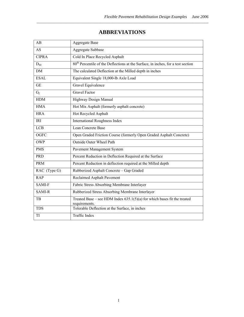
ABBREVIATIONS
AB Aggregate Base
AS Aggregate Subbase
CIPRA Cold In Place Recycled Asphalt
D80 80th Percentile of the Deflections at the Surface, in inches, for a test section
DM The calculated Deflection at the Milled depth in inches
ESAL Equivalent Single 18,000-lb Axle Load
GE Gravel Equivalence
Gf Gravel Factor
HDM Highway Design Manual
HMA Hot Mix Asphalt (formerly asphalt concrete)
HRA Hot Recycled Asphalt
IRI International Roughness Index
LCB Lean Concrete Base
OGFC Open Graded Friction Course (formerly Open Graded Asphalt Concrete)
OWP Outside Outer Wheel Path
PMS Pavement Management System
PRD Percent Reduction in Deflection Required at the Surface
PRM Percent Reduction in deflection required at the Milled depth
RAC (Type G) Rubberized Asphalt Concrete – Gap Graded
RAP Reclaimed Asphalt Pavement
SAMI-F Fabric Stress Absorbing Membrane Interlayer
SAMI-R Rubberized Stress Absorbing Membrane Interlayer
TB Treated Base – see HDM Index 635.1(5)(a) for which bases fit the treated requirements.
TDS Tolerable Deflection at the Surface, in inches
TI Traffic Index
1
Flexible Pavement Rehabilitation Design Examples June 2006 ______________________________________________________________________________________
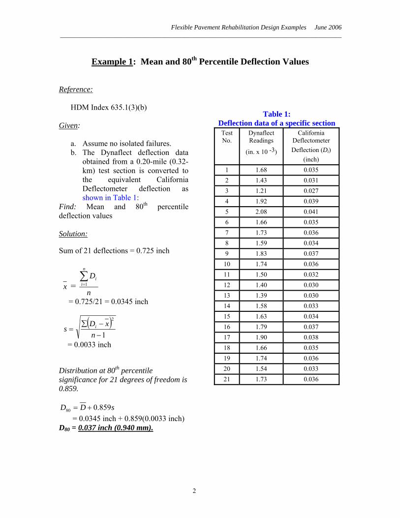
Example 1: Mean and 80th Percentile Deflection Values
Reference:
HDM Index 635.1(3)(b) Given:
a. Assume no isolated failures. b. The Dynaflect deflection data
obtained from a 0.20-mile (0.32-km) test section is converted to the equivalent California Deflectometer deflection as shown in Table 1:
Find: Mean and 80th percentile deflection values Solution:
Sum of 21 deflections = 0.725 inch
x = n
Dn
ii∑
=1
= 0.725/21 = 0.0345 inch
( )
1
2
−−∑
=n
xDs i
= 0.0033 inch
Distribution at 80th percentile significance for 21 degrees of freedom is 0.859.
sDD 859.080 += = 0.0345 inch + 0.859(0.0033 inch) D80 = 0.037 inch (0.940 mm).
Table 1: Deflection data of a specific section Test No.
Dynaflect Readings
(in. x 10 -3)
California Deflectometer Deflection (Di)
(inch) 1 1.68 0.035 2 1.43 0.031 3 1.21 0.027 4 1.92 0.039 5 2.08 0.041 6 1.66 0.035 7 1.73 0.036 8 1.59 0.034 9 1.83 0.037
10 1.74 0.036 11 1.50 0.032 12 1.40 0.030 13 1.39 0.030 14 1.58 0.033 15 1.63 0.034 16 1.79 0.037 17 1.90 0.038 18 1.66 0.035 19 1.74 0.036 20 1.54 0.033 21 1.73 0.036
2

Flexible Pavement Rehabilitation Design Examples June 2006 ______________________________________________________________________________________
Example 2: Deflection Map
A deflection map is a sketch of the project illustrating D80 deflection levels for each test section. The purpose of the deflection map is to show a visual representation in order to determine if certain areas of the project should be grouped and analyzed separately (by observing the differences in deflection levels). Deflection values should not only be looked at along the lane, but from lane to lane and travel direction. Traffic can vary considerably from lane to lane and in opposing directions, thus causing different distress and deflection levels. Rehabilitation requirements and limits can then be determined for each direction or lane. See Figure 1 for an example of a "deflection map."
Figure 1 EXAMPLE OF DEFLECTION MAP
(Not to Scale) Notes:
- All deflections are in terms of equivalent California Deflectometer values. - Pavement deflections taken at 0.01-mile intervals - Traffic Index (__ year) = ____ - Date Tested: _______
Project Limits
Avg. 80th percentile deflection level = 0.029 in.
Avg. 80th percentile deflection level = 0.015 in.
PM 59.0
PM 60.0
PM 61.0
PM 62.0
PM 63.0
PM 64.0
PM 65.0
PM 66.0
24
28
30 30
28 34
13
20 18 13
14 15 14
NB
SB
80th percentile deflections (10-3 inches) for 0.02 mile test sections
28
3
Flexible Pavement Rehabilitation Design Examples June 2006 ______________________________________________________________________________________
Example 3: HMA Overlay #1
Reference:
HDM Index 635.1(5) Overlay procedures for flexible over existing flexible pavement.
Given:
The 20-year Traffic Index (TI20) is 11.0.
Location 80th Percentile Deflection
Existing Structural Section
Existing IRI (from Pavement
Condition Survey) PM 1.00 to
PM 3.50 0.025 inch 0.40 foot HMA
0.67 foot AB 1.00 foot AS
182 in/mile
Find: Give a recommendation of the HMA overlay thickness layer Calculations:
Criterion #1- Structural Adequacy: Step 1:
Obtain tolerable deflection at the surface (TDS). From HDM Table 635.1A (see copy of table on next page for demonstration on how to use) AC = 0.40 ft and TI = 11.0, therefore: TDS = 0.012 inch
Step 2: Compare average D80 to TDS. 0.025 > 0.012 Rehabilitation for structural adequacy is indicated.
Step 3: Calculate Percent Reduction in Deflection (PRD) required.
PRD = ( )10080
80
AverageDTDSAverageD −
= ( ) %52100025.0
012.0025.0=⎟
⎠⎞
⎜⎝⎛ −
Step 4:
Determine Gravel Equivalence (GE) required for deflection reduction. From HDM Table 635.1B GE = 0.68 ft for 52% reduction in deflection.
4

Flexible Pavement Rehabilitation Design Examples June 2006 ______________________________________________________________________________________
Step 5: Determine the required thickness of HMA overlay. From Table 635.1C: Gf for HMA Overlay is 1.9.
ftGGEOverlay
f36.0
9.168.0
=== Round to 0.35-ft
Overlay for structural adequacy = 0.35-ft HMA.
HDM Table 635.1A Tolerable Deflections
AC Thickness T r a f f i c I n d ex ( T I) ( foot ) 5.0 5.5 6.0 6.5 7.0 7.5 8.0 8.5 9.0 9.5 10.0 10.5
0.00 66 58 51 45 41 37 34 31 29 27 25 23 0.05 61 53 47 42 38 34 31 29 27 25 23 21 0.10 57 50 44 39 35 32 29 27 25 23 21 20 0.15 53 46 41 36 33 30 27 25 23 21 20 19 0.20 49 43 38 34 31 28 25 23 21 20 18 17 0.25 46 40 35 32 28 26 24 22 20 19 17 16 0.30 43 37 33 29 27 24 22 20 19 17 16 15 0.35 40 35 31 27 25 22 20 19 17 16 15 14 0.40 37 32 29 26 23 21 19 18 16 15 14 13 0.45 35 30 27 24 21 20 18 16 15 14 13 12
0.50 1 32 28 25 22 20 18 17 15 14 13 12 11 CTB 2 27 24 21 19 17 15 14 13 12 11 10 10
11.0 11.5 12.0 12.5 13.0 13.5 14.0 14.5 15.0 15.5 16.0 16.5
0.00 22 20 19 18 17 16 15 15 14 13 13 12 0.05 20 19 18 17 16 15 14 14 13 12 12 11 0.10 19 18 16 16 15 14 13 13 12 11 11 11 0.15 17 16 15 14 14 13 12 12 11 11 10 10 0.20 16 15 14 14 13 12 12 11 10 10 10 9 0.25 15 14 13 13 12 11 11 10 10 9 9 8 0.30 14 13 12 12 11 11 10 9 9 9 8 8 0.35 13 12 12 11 10 10 9 9 8 8 8 7 0.40 12 11 11 10 10 9 9 8 8 8 7 7 0.45 11 11 10 9 9 9 8 8 7 7 7 6
0.50 1 11 10 9 9 8 8 8 7 7 7 6 6 CTB 2 9 8 8 7 7 7 6 6 6 5 5 5
5

Flexible Pavement Rehabilitation Design Examples June 2006 ______________________________________________________________________________________
Criterion #2 - Reflective Cracking: Per HDM 635.1(5)(b) Reflective Cracking, min HMA overlay = One-half existing HMA thickness x 125%, therefore: Min HMA overlay = (1/2)(0.40-ft)(1.25) = 0.25-ft.
Criterion #3 - Ride Quality:
Per HDM 635.1(5)(c) Ride Quality: If IRI > 170 inches/mile than place minimum 0.25-ft HMA overlay in two layers. Existing IRI = 182 inches/mile > 170 inches/miles, therefore minimum 0.25-ft HMA overlay in two layers applies.
Evaluation: The thickness required to achieve adequate structural adequacy is the thickest of the criteria so the minimum HMA overlay thickness required is 0.35-ft. Recommendation: 0.35-ft overlay of HMA, placed in a minimum of two passes of paving machine Other Considerations: • A 0.35-ft HMA overlay may increase the profile grade beyond the allowable if there
are restraints such as are found in urban areas.
6

Flexible Pavement Rehabilitation Design Examples June 2006 ______________________________________________________________________________________
Example 4: HMA Overlay #2 Reference:
HDM Index 635.1(5) Overlay procedures for flexible over existing flexible pavement
Given:
Ten-Year TI
80th Percentile Deflection
Existing Structural Section
10.0 0.030 inch 0.55 foot HMA 0.50 foot AB 1.00 foot AS
Find: Give a recommendation of the HMA overlay thickness layer Existing conditions: • Occasional to intermittent alligator, transverse, and longitudinal cracks, (some 0.5
inch wide). • Fairly smooth ride (IRI 136 inches/mile per latest Pavement Condition Survey.) Calculations:
Criterion #1- Structural Adequacy:
Step 1: Obtain tolerable deflection at the surface (TDS). From HDM Table 635.1A (see copy of table on next page for demonstration on how to use) AC = 0.55 ft and TI = 10.0 TDS = 0.012 inch
Step 2: Compare average D80 to TDS. 0.030 0.012 Rehabilitation for structural adequacy is indicated.
Step 3: Calculate Percent Reduction in Deflection required.
PRD = ( )10080
80
AverageDTDSAverageD −
= ( ) %60100030.0
012.0030.0=⎟
⎠⎞
⎜⎝⎛ −
Step 4:
Determine Gravel Equivalence (GE) required for deflection reduction. From HDM Table 635.1B
7

Flexible Pavement Rehabilitation Design Examples June 2006 ______________________________________________________________________________________
GE = 0.85 ft for PRD = 60%.
Step 5: Determine the required thickness of HMA overlay for structural adequacy.
ftGGEOverlay
f45.0
9.185.0
=== Use 0.45-ft.
HDM Table 635.1A Tolerable Deflections
AC Thickness T r a f f i c I n d ex ( T I) ( foot ) 5.0 5.5 6.0 6.5 7.0 7.5 8.0 8.5 9.0 9.5 10.0 10.5
0.00 66 58 51 45 41 37 34 31 29 27 25 23 0.05 61 53 47 42 38 34 31 29 27 25 23 21 0.10 57 50 44 39 35 32 29 27 25 23 21 20 0.15 53 46 41 36 33 30 27 25 23 21 20 19 0.20 49 43 38 34 31 28 25 23 21 20 18 17 0.25 46 40 35 32 28 26 24 22 20 19 17 16 0.30 43 37 33 29 27 24 22 20 19 17 16 15 0.35 40 35 31 27 25 22 20 19 17 16 15 14 0.40 37 32 29 26 23 21 19 18 16 15 14 13 0.45 35 30 27 24 21 20 18 16 15 14 13 12
0.50 1 32 28 25 22 20 18 17 15 14 13 12 11 TB 2 27 24 21 19 17 15 14 13 12 11 10 10
11.0 11.5 12.0 12.5 13.0 13.5 14.0 14.5 15.0 15.5 16.0 16.5
0.00 22 20 19 18 17 16 15 15 14 13 13 12 0.05 20 19 18 17 16 15 14 14 13 12 12 11 0.10 19 18 16 16 15 14 13 13 12 11 11 11 0.15 17 16 15 14 14 13 12 12 11 11 10 10 0.20 16 15 14 14 13 12 12 11 10 10 10 9 0.25 15 14 13 13 12 11 11 10 10 9 9 8 0.30 14 13 12 12 11 11 10 9 9 9 8 8 0.35 13 12 12 11 10 10 9 9 8 8 8 7 0.40 12 11 11 10 10 9 9 8 8 8 7 7 0.45 11 11 10 9 9 9 8 8 7 7 7 6
0.50 1 11 10 9 9 8 8 8 7 7 7 6 6 CTB 2 9 8 8 7 7 7 6 6 6 5 5 5
Notes: 1) For an HMA thickness greater than 0.50-ft, use the 0.50 foot depth. 2) Use the TB line to represent treated base materials, regardless of the thickness of HMA.
8

Flexible Pavement Rehabilitation Design Examples June 2006 ______________________________________________________________________________________
Criterion #2 - Reflective Cracking:
Determine half of the existing pavement thickness (HDM 635.1(5)(b) Reflective Cracking):
Overlay = 255.0 = 0.275 Round to 0.30 ft.
Criterion #3 - Ride Quality:
Because the existing IRI of 136 inches/mile is less than the threshold value of 170 inches/mile in HDM 635.1(5)(c) ride quality, the ride quality is determined to be acceptable and the required overlay thickness for ride quality is 0.0-ft.
Discussion: • Since reflective cracking requirement is less than 0.45 ft, and since smoothness is
satisfactory, structural adequacy governs the overlay design thickness. • For this overlay example, reflective cracking could never control, since the structural
requirement of 0.45 ft is already above the 0.35-ft maximum for reflection. • In this example, if the structural requirement had been less than 0.30 ft and the ride
quality needed improvement, then reflective cracking would be the controlling criteria with a required overlay of 0.30-ft.
• A rough-riding pavement can be made smoother by using either of two strategies, a
mill-and-replace strategy or a strategy that places an HMA overlay in two layers. The design of the overlay for ride consideration would be as follows:
Option 1 - The overlay must be thick enough to allow for two layers to be placed. The 0.45-ft HMA overlay for structural adequacy will provide the two layers needed for improving the ride quality. Option 2 - Mill the existing rough pavement to remove much of the surface undulations prior to placing the new HMA overlay. Milling off 0.10 to 0.20 ft will usually be sufficient. Milling will change D80 and require additional design calculations.
Final Recommendation:
0.45-ft HMA overlay.
9

Flexible Pavement Rehabilitation Design Examples June 2006 ______________________________________________________________________________________
Example 5: Mill and Overlay Reference: HDM Index 635.1(6) Mill and Overlay Procedures Given:
Ten-Year TI
80th Percentile Deflection
Existing Structural Section
IRI (from Pavement
Condition Survey) 8.0 0.030 inch 0.55 foot HMA
0.50 foot AB 1.00 foot AS
198 inches/mile
Overlay recommendations to be considered (see Examples 3 and 4 for how to determine these numbers):
Structural Adequacy: A 0.25-ft HMA overlay.
Reflective Cracking: A 0.30-ft HMA overlay.
Ride Quality: A 0.25-ft HMA overlay placed in two layers.
From HDM Table 635.1A: TDS = 0.017 inches. Find: Give a recommendation for the cold recycle depth and cap overlay. Calculation: Start with a minimum milling depth of 0.15 ft and find the deflection at the milled depth:
DM = ( ) ( )⎥⎦
⎤⎢⎣
⎡⎟⎠⎞
⎜⎝⎛+ 8080 D
30%12D
mmMillDepth
DM = (0.030 inch)+[(0.12/0.10 ft)(0.15 ft)(0.030 inch)] = 0.035 inches Determine the Percent Reduction in Deflection at the Milled Depth (PRM):
PRM = ( )100⎟⎠⎞
⎜⎝⎛ −
DMTDSDM
10

Flexible Pavement Rehabilitation Design Examples June 2006 ______________________________________________________________________________________
PRM = [(0.035 inch – 0.017 inch)/0.035 inch](100) PRM = 51.0% < 70 %, the analytical depth. Therefore, use PRM = 51% From HDM Table 635.1B the total GE required is 0.66 ft. Gf for CIPRA is 1.5 from HDM Table 635.1C GE of CIPRA = (MillDepth)(Gf) = (0.15 ft)(1.5) = 0.22 ft Determine the GE that the HMA overlay has to provide: GE of HMA = Total GE required – GE of CIPRA = 0.66 ft – 0.22 ft = 0.44 ft. Thickness of HMA = 0.44 ft/1.9 = 0.23 ft. Round up to 0.25 ft. This is not acceptable since the HMA thickness saved from the basic overlay is only (0.30 ft – 0.25 ft) = 0.05 ft. This should be at least 0.10 ft. Try again.
Trial 2: Increase the milling depth to 0.20 ft and find the deflection at the milled depth:
DM = (0.030 inch) + [(0.12/0.10 ft)(0.20 ft) (0.030 inch)] = 0.037 inch
PRM = [(0.037 inch – 0.017 inch)/0.037 inch](100) = 54%
54% < 70%, the analytical depth.
Therefore, use PRM = 54% From HDM Table 635.1B the total GE required is 0.72 ft.
GE of CIPRA = (MillDepth)(Gf) = (0.20 ft)(1.5) = 0.30 ft
GE of HMA = Total GE required – GE of CIPRA
= 0.72 ft – 0.30 ft = 0.42 ft
Thickness of HMA = 0.42 ft/1.9 = 0.22 ft. Round up to 0.25 ft.
The results did not change for the HMA thickness saved from the basic overlay. This should be at least 0.10 ft. Try again.
Trial 3: Increase the milling depth to 0.25 ft and find the deflection at the milled depth:
DM = (0.030 inch) + [(0.12/ 0.10 ft)(0.25 ft) (0.030 inch)] = 0.039 inch
11

Flexible Pavement Rehabilitation Design Examples June 2006 ______________________________________________________________________________________
PRM = [(0.039 inch – 0.017 inch)/0.039 inch](100) = 56.4%
56.4% < 70%, the analytical depth.
Therefore, use PRM = 56.4%
From HDM Table 635.1B the total GE required is 0.77 ft.
GE of CIPRA = (0.25 ft)(1.5) = 0.38 ft
GE of HMA = Total GE required – GE of CIPRA = 0.77 ft – 0.38 ft = 0.39 ft
Thickness of HMA = 0.39 ft/1.9 = 0.21 ft. Round up to 0.25 ft.
Again the results did not change for the HMA thickness saved from the basic overlay. This should be at least 0.10 ft. Try again.
Trial 4: Increase the milling depth to 0.30 ft and find the deflection at the milled depth:
DM = (0.030 inch) + [(0.12/0.10 ft)(0.30 ft) (0.030 inch)] = 0.041 inch
PRM = [(0.041 inch – 0.017 inch)/0.041 inch](100) = 58.5%
58.5 < 70%, the analytical depth.
Therefore, use PRM = 58.5% From HDM Table 635.1B, the total GE required is 0.82 ft.
GE of CIPRA = (0.30 ft)(1.5) = 0.45 ft
GE of HMA = Total GE required – GE of CIPRA = 0.82 ft – 0.45 ft = 0.37 ft
Thickness of HMA = 0.37 ft/1.9 = 0.19 ft. Round up to 0.20 ft.
Discussion:
When compared to the basic overlay design, CIPRA saves 0.10 ft of virgin HMA and would also decrease the final profile grade of the shoulder thus saving shoulder-backing material.
Now that the first consideration has been met, consider volume. For a project 10 miles long and pavement 24 feet wide would this produce enough CIPRA material to be cost effective? Assuming a compacted HMA density of 145 lbs/ft3, the milling tonnage is
12
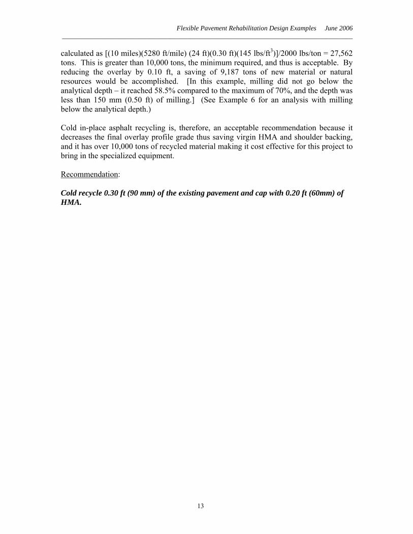
Flexible Pavement Rehabilitation Design Examples June 2006 ______________________________________________________________________________________
calculated as [(10 miles)(5280 ft/mile) (24 ft)(0.30 ft)(145 lbs/ft3)]/2000 lbs/ton = 27,562 tons. This is greater than 10,000 tons, the minimum required, and thus is acceptable. By reducing the overlay by 0.10 ft, a saving of 9,187 tons of new material or natural resources would be accomplished. [In this example, milling did not go below the analytical depth – it reached 58.5% compared to the maximum of 70%, and the depth was less than 150 mm (0.50 ft) of milling.] (See Example 6 for an analysis with milling below the analytical depth.) Cold in-place asphalt recycling is, therefore, an acceptable recommendation because it decreases the final overlay profile grade thus saving virgin HMA and shoulder backing, and it has over 10,000 tons of recycled material making it cost effective for this project to bring in the specialized equipment. Recommendation: Cold recycle 0.30 ft (90 mm) of the existing pavement and cap with 0.20 ft (60mm) of HMA.
13

Flexible Pavement Rehabilitation Design Examples June 2006 ______________________________________________________________________________________
Example 6: Mill and Overlay Below the Analytical Depth Reference: HDM Index 635.1(6) Mill and Overlay Procedures Given:
Ten-Year TI
80th Percentile Deflection
Existing Structural Section
IRI (from Pavement
Condition Survey) 11.0 0.031 inch 0.75 foot HMA
0.50 foot AB 1.00 foot AS
144 inches/mile
Milled HMA to be transported to and hot recycled at plant for re-use on the project.
Find: Give a recommendation of the mill depth of existing pavement, and new overlay thickness.
Overlay recommendations to be considered (see Examples 3 and 4 for how to determine these numbers):
Structural Adequacy: A 0.50-ft HMA overlay.
Reflective Cracking: A 0.35-ft HMA overlay. (One-half existing HMA thickness with a maximum of 0.35 ft.)
Ride Quality: A 0.25-ft HMA overlay placed in two layers is not required.
From HDM Table 635.1A, using 0.5 ft and TI of 11 we get the TDS of 0.011 inch.
Calculation:
Start with a milling depth of 0.15 ft and find the deflection at the milled depth
DM = ( ) ( )⎥⎦
⎤⎢⎣
⎡⎟⎟⎠
⎞⎜⎜⎝
⎛+ 8080 D
10.0%12D
ftMillDepth
DM = (0.031 inch) + [(0.12/0.10ft)(0.15 ft)(0.031 inch)] = 0.037 inch
Determine the Percent Reduction in Deflection at the Milled Depth (PRM):
14

Flexible Pavement Rehabilitation Design Examples June 2006 ______________________________________________________________________________________
PRM = ( )100⎟⎠⎞
⎜⎝⎛ −
DMTDSDM
PRM = [(0.037 inch – 0.011 inch)/0.037 inch](100)
PRM = 69.9% ≈ 70%, the analytical depth.
Therefore, use PRM = 69.9%
From HDM Table 635.1C the total GE required is 1.06 ft.
Find the hot recycled asphalt thickness: GE/Gf = 1.06 ft/1.9 = 0.56 ft. Round to 0.55 ft.
The increase in grade is (0.55 ft – 0.15 ft) = 0.40 ft. This is acceptable since the reduction in profile grade from the basic overlay is 0.10 ft. This would save 0.10 ft of virgin HMA and would also decrease the final grade of the shoulder thus saving shoulder-backing material.
The quantity for milling 0.15 ft in two lanes per mile is calculated as follows:
[(1 mile)(5280 ft/mile)(24 ft)(0.15 ft)(145 lbs/cu ft)]/2000 lbs/ton = 1,378 tons. The project should be long enough (and/or wide enough) to provide at least 10,000 tons for recycling. 10,000 tons/1,378 tons per mile = 7.3 miles.
The percentage RAP in the mix is (0.15 ft milled/0.55 ft hot recycled asphalt thickness)(100) = 27%. In order to get more RAP and use less virgin material, the milling depth should be increased.
Since the analytical depth was nearly reached (69.9%) at the milled depth of 0.15 ft, all milled and removed material below that level will be considered to be material with a Gf of 1.4.
Trial 2: Increase the milled depth to 0.25 ft (0.10 ft below the analytical depth) to save more material. Total thickness of the hot recycled asphalt = [(GE required at 0.15 ft milled depth) + (GE required due to additional milling)]/1.9.
Hot recycled asphalt = [(1.06 ft) + (0.10 ft)(1.4)]/1.9 = 0.63 ft of hot recycled asphalt. Round to 0.65 ft.
The percent of RAP is (Mill Depth/Hot Recycled Asphalt Depth) (0.25 ft/0.65 ft)(100) = 38 %.
15

Flexible Pavement Rehabilitation Design Examples June 2006 ______________________________________________________________________________________
Trial 3: Increase the milled depth to 0.30 ft (0.15 ft below the analytical depth) to save more material.
Hot recycled asphalt = [(1.06 ft) + (0.15 ft)(1.4)]/1.9 = 0.67 ft. Round to 0.65 ft.
The percent of RAP is (0.30 ft/0.65 ft)(100) = 46 %.
Discussion: At this milling depth the RAP content is 46% and the increase in grade is 0.35 ft. This will save 0.15 ft of new material compared with the 0.50 ft HMA overlay needed by the basic overlay and would also decrease the final grade of the shoulder thus saving shoulder-backing material. Recommendation: Mill 0.30 ft of the existing pavement and then replace it with a total thickness of 0.65 ft of hot recycled asphalt.
16

Flexible Pavement Rehabilitation Design Examples June 2006 ______________________________________________________________________________________
Example 7: Remove and Replace (Partial Depth) Reference: HDM Index 635.1(6) Mill and Overlay Procedures Given:
Ten-Year TI
80th Percentile Deflection
Existing Structural Section
IRI (from Pavement
Condition Survey) 12.0 0.030 inch 0.75 foot HMA
0.50 foot AB 0.83 foot AS
205 inches/mile
Find: Give a recommendation on the mill depth and overlay thicknesses while maintaining the profile grade. Calculation: First, solve for Basic Overlay (HDM 635.1(5) Overlay Procedures for Flexible over Existing Flexible Pavement): Structural Adequacy:
Use HDM Table 635.1A to find that the TDS is 0.009 inches.
PRD = [(0.030 inches – 0.009 inches)/0.030 inches](100) = 70.0 %
From HDM Table 635.1B, the increase in GE required to reduce the D80 to the tolerable deflection level is 1.06 ft. From Table 635.1C, the Gf for HMA is 1.9.
HMA overlay thickness = (1.06 ft)/(1.9) = 0.56 ft. Round to 0.55 ft Reflective Cracking:
A 0.35-ft HMA overlay. (One-half existing HMA thickness with a maximum of 0.35 ft.)
Ride Quality:
Does not need to be considered for a Remove and Replace design per HDM 635.1(7) Remove and Replace
Now provide a rehabilitation strategy by the remove and replace – partial depth method that maintains the existing profile grade.
17

Flexible Pavement Rehabilitation Design Examples June 2006 ______________________________________________________________________________________
In this example, the analytical depth of 70% was reached at the surface, so to obtain the GE below the surface, all the calculations will be multiplying the Gf times the thickness of the layer milled. These values will then be added to the GE required at the surface.
Find the GE removed when milling from the analytical depth (the surface in this example) down to the bottom of the pavement: GE = (0.75 ft)(1.4) = 1.05 ft.
This is added to the GE at the surface and divided by the Gf of the new HMA to get the thickness required: (1.06 ft) + (1.05 ft) = 2.11 ft GE.
This is a trial and error problem since the Gf that matches the new HMA thickness is unknown at this time. From top 633.1(c) Empirical Method we use these equations
t=thickness
⎟⎟⎠
⎞⎜⎜⎝
⎛=⇒≤ 1/2(TI)
67.5G5.0 fftt
⎟⎟⎠
⎞⎜⎜⎝
⎛=⇒> 1/2
3/1
(TI))()0.7(G5.0 tftt f
Given that: ⎟⎠⎞
⎜⎝⎛=
f
GEtG
This is a trial and error problem.
We start by assuming that t <0.5 ft, therefore we use:
64.1(12)
67.5G 1/2 =⎟⎟⎠
⎞⎜⎜⎝
⎛=f
∴GE/Gf =(2.11 ft / 1.64) = 1.29 ft > 1.05 ft, since they are not close in value, we next assume that t > 0.5 ft and we use the thickness calculated to start with.
20.2(12)
)29.1()0.7(G 1/2
3/1
=⎟⎟⎠
⎞⎜⎜⎝
⎛=f
GE/Gf =(2.11 ft / 2.20) = 0.96 ft, not equal to 1.29 ft try again.
Try 1.05 ft
05.2(12)
)05.1()0.7(G 1/2
3/1
=⎟⎟⎠
⎞⎜⎜⎝
⎛=f
18
Flexible Pavement Rehabilitation Design Examples June 2006 ______________________________________________________________________________________
GE/Gf = (2.11 ft)/2.05 = 1.03 ft, not equal to 1.05 ft try again.
Try 1.03 ft
04.2(12)
)03.1()04.1(G 1/2
3/1
=⎟⎟⎠
⎞⎜⎜⎝
⎛=f
GE/Gf = 2.11 ft / 2.04 = 1.03 which matches the thickness for which the Gf was used.
Therefore use 1.3 ft of HMA
Alternative method:
Using HDM Table 633.1, given TI=12 and GE of 2.11 ft, we go under the corresponding TI down the column to 650 mm, because there is no 645 mm, we move to the left and se that the actual HMA thickness is 315 mm.
When the milling extends to the bottom of the pavement (0.75 ft), the removed material is replaced with 1.05 ft of HMA for an increase in the profile grade of 0.30 ft. This is 0.25 ft lower in profile grade than the basic overlay design method provided. This would be an acceptable solution except the problem was to match the existing grade.
Therefore, find to what depth the milling has to go to have no increase in profile grade. Below the pavement the Gf for the existing 0.50 ft of AB material is 1.1. The additional GE to be replaced is 1.1 times the thickness of the AB layer milled. This will be added to the GE at the analytical depth (at the surface in this example) and the GE at the bottom of the pavement; then the total is divided by the Gf of the new HMA.
Instead of trying each 0.05-ft of milling, estimate to what depth the milling might have to go. A quick calculation of the Gf ratio times the increase in grade, when milling stopped at the bottom of the pavement, is one way that sometimes works to estimate the needed additional depth below the pavement.
[(1.9)/(1.1)](0.30 ft) = 0.52 ft. Round to 0.50 ft.
This would be a total depth of 1.25 ft (0.75 ft + 0.50 ft).
Find the GE value of the AB removed to the estimated depth (0.50 ft):
GE = (0.50 ft)(1.1) = 0.55 ft.
19
Flexible Pavement Rehabilitation Design Examples June 2006 ______________________________________________________________________________________
This is added to the GE’s at the analytical depth and bottom of the pavement, and then divided by the Gf of the HMA to yield the required thickness:
GE = (1.06 ft) + (1.05 ft) + (0.55 ft) = 2.66 ft.
For the estimated 1.25 ft depth, the Gf is 2.18 (HDM Table 633.1).
GE/Gf = (2.66 ft)/2.18 = 1.22 ft of HMA. Round to 1.20 ft.
This is less than the 1.25-ft thickness that was estimated; the depth of the AB to be removed was too much. Therefore, reduce the estimate for the milled depth of the AB below the pavement. Try 0.45 ft into the AB, for a total thickness of 1.20 ft (0.75-ft pavement and 0.45 ft base).
GE = (0.45 ft)(1.1) = 0.50 ft. This is added to the GE’s at the analytical depth and bottom of the pavement, then divided by the Gf of the 1.20 ft of HMA obtained from HDM Table 633.1 (Gf = 2.15):
GE/Gf = (1.06 ft + 1.05 ft + 0.50 ft)/2.15 = 1.21 ft
Round to 1.20 ft. (This matches the thickness for which the Gf was used).
Discussion:
Since this is quite deep for the milling analysis the Remove and Replace – partial depth method, check using the New Construction Empirical method in HDM Index 633.1 to see if it is close to the 1.20-ft thickness. Only 0.05 ft of AB remains above the aggregate subbase (AS), therefore use the R-value of the AS with the TI10 of 12. (The R-value is 50 for Class 1 and 2, and 40 for Class 3 as per HDM Table 633.1). Assume an R-value of 50. The equation to determine the GE using the R-value is as follows:
GE required=(0.0032)(TI)(100–R) where R is the California R-value for the material below the removal depth.
GE = (0.0032)(12)(100-50) = 1.92
For a full depth design, add a safety factor to the GE of 0.10 ft to allow for construction tolerances as per the HDM. The GE required is then 2.02 ft.
Since we expect to be close to the same depth determined by the deflection method (a good place to start), use a Gf of 2.15 for the determined 1.20-ft of HMA. (HDM Table 633.1).
GE/Gf = (2.02 ft)/(2.15) = 0.94 ft. Round to 0.95 ft.
This is less than the estimated depth of 1.2 ft. The Gf needs to be lower to increase the depth and balance the equation. Try a Gf of 2.02 for a 1.00-ft thickness.
GE/Gf = (2.02 ft)/(2.02) = 1.00 ft.
20
Flexible Pavement Rehabilitation Design Examples June 2006 ______________________________________________________________________________________
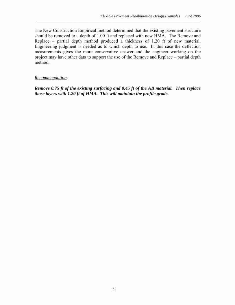
The New Construction Empirical method determined that the existing pavement structure should be removed to a depth of 1.00 ft and replaced with new HMA. The Remove and Replace – partial depth method produced a thickness of 1.20 ft of new material. Engineering judgment is needed as to which depth to use. In this case the deflection measurements gives the more conservative answer and the engineer working on the project may have other data to support the use of the Remove and Replace – partial depth method.
Recommendation: Remove 0.75 ft of the existing surfacing and 0.45 ft of the AB material. Then replace those layers with 1.20 ft of HMA. This will maintain the profile grade.
21