flexible pavement design manual · flexible pavement design manual published by florida department...
TRANSCRIPT

FLEXIBLE PAVEMENT DESIGN MANUAL PUBLISHED BY FLORIDA DEPARTMENT OF TRANSPORTATION PAVEMENT MANAGEMENT OFFICE 605 SUWANNEE STREET, M.S. 70 TALLAHASSEE, FLORIDA 32399-0450 DOCUMENT NO. 625-010-002-f JANUARY 2005
UPDATES TO THIS MANUAL WILL BE ANNOUNCED ON PAVEMENT MANAGEMENT WEB SITE. ADDRESS: http://www.dot.state.fl.us/pavementmanagement
i
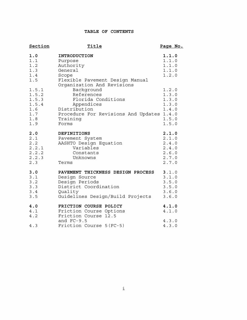
TABLE OF CONTENTS Section Title Page No. 1.0 INTRODUCTION 1.1.0 1.1 Purpose 1.1.0 1.2 Authority 1.1.0 1.3 General 1.1.0 1.4 Scope 1.2.0 1.5 Flexible Pavement Design Manual Organization And Revisions 1.5.1 Background 1.2.0 1.5.2 References 1.3.0 1.5.3 Florida Conditions 1.3.0 1.5.4 Appendices 1.3.0 1.6 Distribution 1.4.0 1.7 Procedure For Revisions And Updates 1.4.0 1.8 Training 1.5.0 1.9 Forms 1.5.0 2.0 DEFINITIONS 2.1.0 2.1 Pavement System 2.1.0 2.2 AASHTO Design Equation 2.4.0 2.2.1 Variables 2.4.0 2.2.2 Constants 2.6.0 2.2.3 Unknowns 2.7.0 2.3 Terms 2.7.0 3.0 PAVEMENT THICKNESS DESIGN PROCESS 3.1.0 3.1 Design Source 3.1.0 3.2 Design Periods 3.5.0 3.3 District Coordination 3.5.0 3.4 Quality 3.6.0 3.5 Guidelines Design/Build Projects 3.6.0 4.0 FRICTION COURSE POLICY 4.1.0 4.1 Friction Course Options 4.1.0 4.2 Friction Course 12.5
and FC-9.5 4.3.0 4.3 Friction Course 5(FC-5) 4.3.0
ii
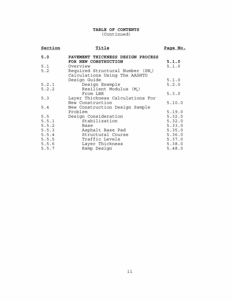
TABLE OF CONTENTS (Continued) Section Title Page No. 5.0 PAVEMENT THICKNESS DESIGN PROCESS
FOR NEW CONSTRUCTION 5.1.0 5.1 Overview 5.1.0 5.2 Required Structural Number (SNR)
Calculations Using The AASHTO Design Guide 5.1.0
5.2.1 Design Example 5.2.0 5.2.2 Resilient Modulus (MR)
From LBR 5.3.0 5.3 Layer Thickness Calculations For
New Construction 5.10.0 5.4 New Construction Design Sample
Problem 5.19.0 5.5 Design Consideration 5.32.0 5.5.1 Stabilization 5.32.0 5.5.2 Base 5.33.0 5.5.3 Asphalt Base Pad 5.35.0 5.5.4 Structural Course 5.36.0 5.5.5 Traffic Levels 5.37.0 5.5.6 Layer Thickness 5.38.0 5.5.7 Ramp Design 5.48.0
iii
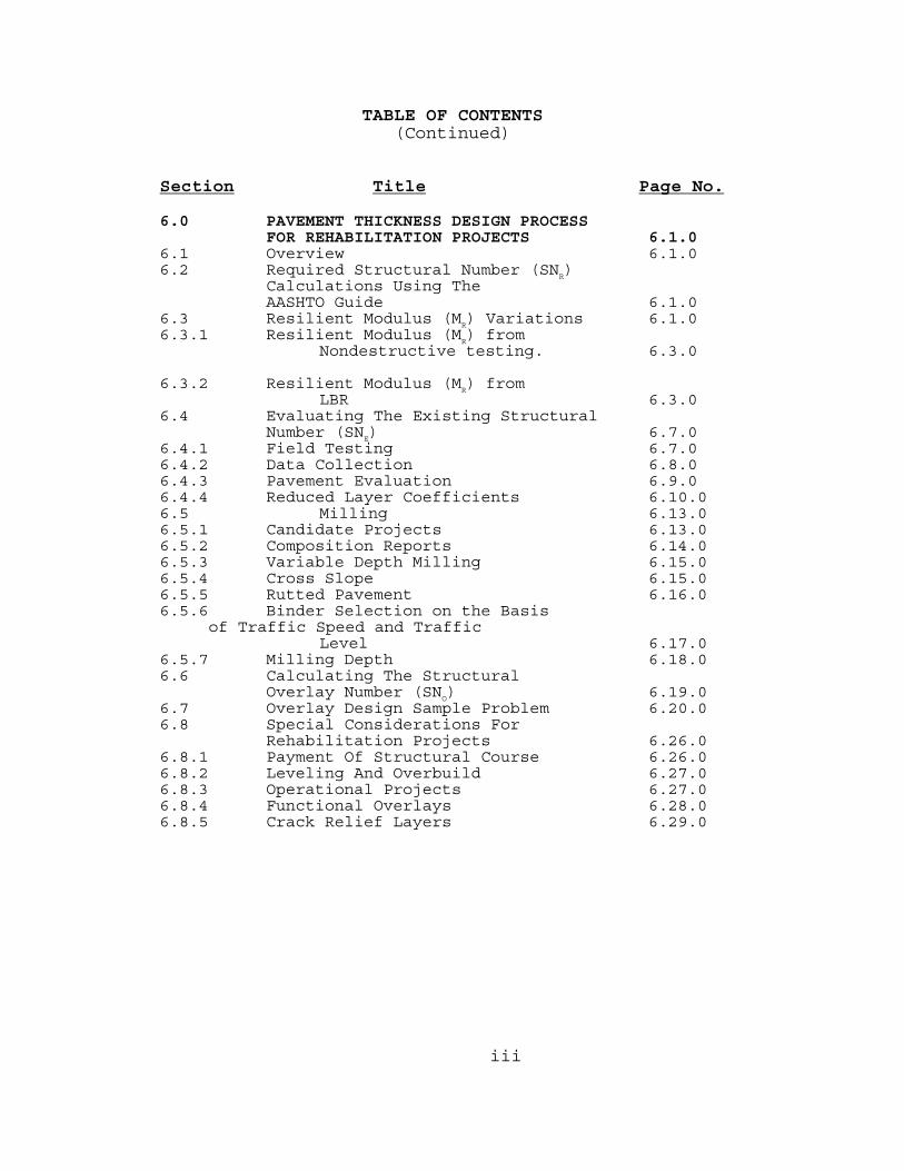
TABLE OF CONTENTS (Continued) Section Title Page No. 6.0 PAVEMENT THICKNESS DESIGN PROCESS
FOR REHABILITATION PROJECTS 6.1.0 6.1 Overview 6.1.0 6.2 Required Structural Number (SN
R)
Calculations Using The AASHTO Guide 6.1.0
6.3 Resilient Modulus (MR) Variations 6.1.0
6.3.1 Resilient Modulus (M ) from R
Nondestructive testing. 6.3.0 6.3.2 Resilient Modulus (M ) from
R
LBR 6.3.0 6.4 Evaluating The Existing Structural
Number (SN ) 6.7.0 E
6.4.1 Field Testing 6.7.0 6.4.2 Data Collection 6.8.0 6.4.3 Pavement Evaluation 6.9.0 6.4.4 Reduced Layer Coefficients 6.10.0 6.5 Milling 6.13.0 6.5.1 Candidate Projects 6.13.0 6.5.2 Composition Reports 6.14.0 6.5.3 Variable Depth Milling 6.15.0 6.5.4 Cross Slope 6.15.0 6.5.5 Rutted Pavement 6.16.0 6.5.6 Binder Selection on the Basis of Traffic Speed and Traffic
Level 6.17.0 6.5.7 Milling Depth 6.18.0 6.6 Calculating The Structural
Overlay Number (SNO) 6.19.0
6.7 Overlay Design Sample Problem 6.20.0 6.8 Special Considerations For
Rehabilitation Projects 6.26.0 6.8.1 Payment Of Structural Course 6.26.0 6.8.2 Leveling And Overbuild 6.27.0 6.8.3 Operational Projects 6.27.0 6.8.4 Functional Overlays 6.28.0 6.8.5 Crack Relief Layers 6.29.0
iv
TABLE OF CONTENTS (Continued)
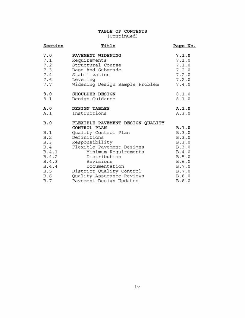
Section Title Page No. 7.0 PAVEMENT WIDENING 7.1.0 7.1 Requirements 7.1.0 7.2 Structural Course 7.1.0 7.3 Base And Subgrade 7.2.0 7.4 Stabilization 7.2.0 7.6 Leveling 7.2.0 7.7 Widening Design Sample Problem 7.4.0 8.0 SHOULDER DESIGN 8.1.0 8.1 Design Guidance 8.1.0 A.0 DESIGN TABLES A.1.0 A.1 Instructions A.3.0 B.0 FLEXIBLE PAVEMENT DESIGN QUALITY
CONTROL PLAN B.1.0 B.1 Quality Control Plan B.3.0 B.2 Definitions B.3.0 B.3 Responsibility B.3.0 B.4 Flexible Pavement Designs B.3.0 B.4.1 Minimum Requirements B.4.0 B.4.2 Distribution B.5.0 B.4.3 Revisions B.6.0 B.4.4 Documentation B.7.0 B.5 District Quality Control B.7.0 B.6 Quality Assurance Reviews B.8.0 B.7 Pavement Design Updates B.8.0
v
TABLE OF CONTENTS (Continued)
C.0 FLEXIBLE PAVEMENT DESIGN ANALYSIS COMPUTER PROGRAM C.1.0 AASHTOWARE DARWin C.4.0 D.0 ESTIMATING DESIGN 18-KIP (80 KILONEWTON)
EQUIVALENT SINGLE AXLE LOADS (ESALD) D.1.0
D.1 Background D.3.0 D.2 Basic Equation D.5.0 D.3 Sample Problems D.8.0 D.3.1 Sample Problem #1 D.8.0 D.3.2 Sample Problem #2 D.11.0
vi
FIGURES Figure Title Page No. 2.1 Roadway Typical Section 2.3.0 3.1 AASHTO Design Equation For
Flexible Pavement 3.2.0 3.2 AASHTO Design Equation Input For
Flexible Pavement 3.3.0 3.3 Flexible Pavement Design Variables 3.4.0 4.1 Illustration Showing Limits Of
Friction Course FC-5 At Intermediate Median Crossover 4.5.0
4.2 Illustration Showing Limits Of
Friction Course FC-5 At Intermediate Median Crossover 4.6.0
4.3 Illustration Showing Limits Of
Friction Course FC-5 At Median Areas Of Low Volume Intersection 4.7.0
5.1 Relationship Between Resilient
Modulus (MR) And Limerock Bearing Ratio (LBR) 5.5.0
6.1 Flexible Pavement Rehabilitation
Process 6.2.0 6.2 Example Deflection Plot 6.4.0 6.3 Example Deflection Plot 6.5.0 6.4 Example Deflection Plot 6.6.0 7.1 Widening Detail For Sample Problem 7.7.0
vii
TABLES Table Title Page No. 3.1 Design Periods 3.7.0 4.1 Asphalt Concrete Friction Course
Selection 4.2.0 5.1 Relationship Between Resilient
Modulus (M ) And Limerock Bearing R
Ratio (LBR) Sample Values 5.6.0 5.2 Reliability (%R) For Different
Roadway Facilities 5.7.0 5.3 Required Structural Number (SN
R)
90% Reliability (%R) Resilient Modulus (M
R) Range 4,000 to
18,000 psi (30 MPa to 100 MPa) (From Appendix A, Table A.4A) 5.8.0
5.9.0 5.4 Structural Coefficients For
Different Pavement Layers 5.12.0 5.5 Recommended Minimum Thickness For
New Construction 5.13.0 5.6 General Use Optional Base Groups
And Structural Numbers (Standard Index 514) 5.14.0
thru 5.15.0 5.7 Limited Use Optional Base Groups
And Structural Numbers (Standard Index 514) 5.16.0
thru 5.17.0 5.8 Notes For Optional Base Groups
And Structural Numbers (Standard Index 514) 5.18.0
5.9 Combined Structural Number 5.29.0
thru 5.31.0
viii
TABLES (Continued)
5.10 Design Notes On Layer Thickness 5.41.0 thru For Asphalt Concrete Structural thru 5.14 Courses 5.47.0 6.1 Reduced Structural Coefficients
Of Asphalt Materials Per Unit thickness 6.11.0
A.1A Required Structural Number (SNR) A.5.0 thru Thru A.10B A.45.0 D.1 Relationship Of Axle Weight To
Damage D.4.0 D.2 Lane Factors (LF) For Different
Types Of Facilities D.6.0 D.3 Equivalency Factors E18(E80) For
Different Types Of Facilities D.7.0
ix
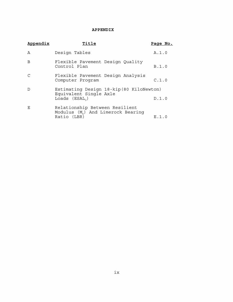
APPENDIX Appendix Title Page No. A Design Tables A.1.0 B Flexible Pavement Design Quality
Control Plan B.1.0 C Flexible Pavement Design Analysis
Computer Program C.1.0 D Estimating Design 18-kip(80 KiloNewton)
Equivalent Single Axle Loads (ESALD) D.1.0
E Relationship Between Resilient
Modulus (MR) And Limerock Bearing Ratio (LBR) E.1.0
Page 1.1.0
Approved: Pavement Management Office Topic Number: 625-010-002-f Effective: January 1, 2005
____________________ Bruce Dietrich, P.E. State Pavement Design Engineer
FLEXIBLE PAVEMENT DESIGN MANUAL
CHAPTER 1
INTRODUCTION 1.1 PURPOSE The objective of this manual is to provide a Pavement Design Engineer with sufficient information so that the necessary input data can be developed and proper engineering principles applied to design a new flexible pavement, or develop a properly engineered rehabilitation project. This design manual addresses methods to properly develop a rehabilitation project, pavement milling, and the computations necessary for the pavement design process. It is the responsibility of the Pavement Design Engineer to insure that the designs produced conform to Department policies, procedures, standards, guidelines, and good engineering practices. 1.2 AUTHORITY Section 334.044(2), Florida Statutes 1.3 GENERAL Chapter 334 of the Florida Statutes, known as the Florida Transportation Code, establishes the responsibilities of the state, counties, and municipalities for the planning and development of the transportation systems serving the people of the State of Florida, with the objective of assuring development of an integrated, balanced statewide system.
Page 1.2.0
The Code's purpose is to protect the safety and general welfare of the people of the State and to preserve and improve all transportation facilities in Florida. Under Section 334.044, the Code sets forth the powers and duties of the Department of Transportation to develop and adopt uniform minimum standards and criteria for the design, construction, maintenance, and operation of public roads. The standards in this manual represent minimum requirements which must be met for flexible pavement design for new construction and pavement rehabilitation of Florida Department Of Transportation projects. Any variances should be documented in project files. Pavement design is primarily a matter of sound application of acceptable engineering criteria and standards. While the standards contained in this manual provide a basis for uniform design practice for typical pavement design situations, precise rules which would apply to all possible situations are impossible to give. 1.4 SCOPE The principal users of this manual are the District Pavement Design Engineers and their agents (ie. Consultants). Additional users include other department offices such as Construction, Maintenance, Traffic Operations, etc., and city and county offices. 1.5 FLEXIBLE PAVEMENT DESIGN MANUAL ORGANIZATION
AND REVISIONS 1.5.1 BACKGROUND The manual (Topic No.625-010-002-f) is published as a revision, using English and Metric values.
Page 1.3.0
1.5.2 REFERENCES The design procedures incorporated in this document are based on the American Association of State Highway and Transportation Officials (AASHTO) Guide for Design of Pavement Structures plus numerous National Council on Highway Research Projects (NCHRP), Transportation Research Board (TRB), and Federal Highway Administration (FHWA) publications. The specifics addressed in this manual have been tailored to Florida conditions, materials, and policy. 1.5.3 FLORIDA CONDITIONS A number of coefficients and variables are specified in this manual. They should be considered as standard values for typical Florida projects. There may be instances where a variance from the values would be appropriate. In these instances, the Pavement Design Engineer will stay within the bounds established by the basic AASHTO Design Guide, justify the variance, and document the actions in the Pavement Design File. 1.5.4 APPENDICES Included with this manual are 4 appendices:
Appendix Contents
A Design Tables.
B Flexible Pavement Design Quality Control Plan.
C Flexible Pavement Design Analysis
Computer Program.
D Estimating Design 18-kip(80- kiloNewton)Equivalent Single Axle Loads (ESALD).
E Relationship Between Resilient
Modulus (MR) And Limerock Bearing Ratio (LBR)
Page 1.4.0
1.6 DISTRIBUTION This document is available through the Maps and Publications Section. Manuals may be purchased from:
Florida Department of Transportation Map and Publication Sales Mail Station 12 605 Suwannee Street Tallahassee, FL 32399-0450
Telephone (850) 414-4050 SUN COM 994-4050 FAX Number (850) 414-4915 http://www.dot.state.fl.us/mapsandpublications
Contact the above office for latest price information. Authorized Florida Department Of Transportation personnel may obtain the manual from the above office at no charge with the appropriate cost center information. 1.7 PROCEDURE FOR REVISIONS AND UPDATES Flexible Pavement Design Manual holders are solicited for comments and suggestions for changes to the manual by writing to the address below:
Florida Department Of Transportation Pavement Management Section 605 Suwannee Street, M.S.32 Tallahassee, Florida 32399-0450
Each idea or suggestion received will be reviewed by appropriate pavement design staff in a timely manner. Items warranting immediate change will be made with the approval of the State Pavement Design Engineer in the form of a Pavement Design Bulletin.
Page 1.5.0
Pavement Design Bulletins for the Flexible Pavement Design Manual are distributed to the District Design Engineers, District Pavement Design Engineers, District Consultant Pavement Management Engineers and posted on, F.D.O.T.website.http://www.dot.state.fl.us/pavementmanagement. Pavement Design Bulletins will be in effect until the official manual revision. Statewide meetings of District Roadway Design Engineers will be held quarterly and a statewide meeting of designers may be held annually. A major agenda item at these meetings will be the review of Design Bulletins, planned revisions, and suggestions and comments that may warrant revisions. Based on input from these meetings, official revisions are developed and distributed to the District Design Engineers, District Pavement Design Engineers, Consultant Project Managers, Roadway Design Office, State Materials Office, Federal Highway Administration, industry and other appropriate offices as necessary. All revisions and updates will be coordinated with the Organization, Forms and Procedures Office prior to implementation to ensure conformance with and incorporation into the Department=s standard operating system. 1.8 TRAINING No mandatory training is required by this procedure. Classes on the manual are available on request by the District Pavement Design Engineer. 1.9 FORMS No forms are required by this procedure.
Page 1.6.0
(THIS PAGE HAS BEEN LEFT INTENTIONALLY BLANK)
Page 2.1.0
CHAPTER 2
DEFINITIONS 2.1 PAVEMENT SYSTEM The following define the general pavement layers in a flexible pavement system. Some of the most important layers are shown in Figure 2.1. The definitions are presented "top-down" through the pavement structure with the stronger layers on top of the weaker layers. The concept of stronger layers on top of weaker layers, as load stresses are spread out and down through the pavement, is further supported by the horizontal extension of weaker layers beyond stronger layers in a pyramidal effect (See Figure 2.1). Standard department practice is to extend the base 4"(0.1 m) beyond the edge of the structural course. This is very important when dealing with granular materials. Without this support, vehicle loads would cause failure along the pavement edge. The pavement structure or system as it is sometimes referred to, is the pavement layers designed to support traffic loads and distribute them to the roadbed soil or select embankment material. Friction Course The friction course is the uppermost pavement layer and is designed to provide a skid resistant surface. The following friction courses are used by the Department: • Friction Course FC-12.5 is a dense graded mix and is
placed approximately 1 1/2" thick (40 mm thick). • Friction Course FC-9.5 is a dense graded mix and is
placed approximately 1.0" thick (30 mm thick). • Friction Course or FC-5 is an open graded mix and is
placed approximately 3/4" thick (20 mm thick).
Page 2.2.0
Structural Course The structural course is designed to distribute the traffic loadings to the base course. The following structural courses are used by the Department: • Structural Course Type SP-9.5 uses a 3/8"(9.5 mm)
nominal maximum size aggregate. • Structural Course Type SP-12.5 uses a 1/2"(12.5 mm)
nominal maximum size aggregate. • Structural Course Type SP-19.0 uses a 3/4"(19.0 mm)
nominal maximum size aggregate. Old Mixes Type S-I, S-II, S-III, FC-1, FC-2, FC-3, FC-4, Type I, II and III Asphaltic Concrete, Binder, and Asphaltic Concrete base mixes will be encountered on rehabilitation projects but are not currently designed by the Department. Leveling and Overbuild Course The Leveling and Overbuild Courses are used for surface leveling, longitudinal profile and cross-slope correction. Base Course The base course is a course (or courses) of specified material and design thickness, which supports the structural course and distributes the traffic loads to the subbase or subgrade. Different base course materials that may have different thickness, that are structurally equivalent, are grouped together to form an optional base group. More detailed information can be found in Section 5 of this manual or Standard Index 514.
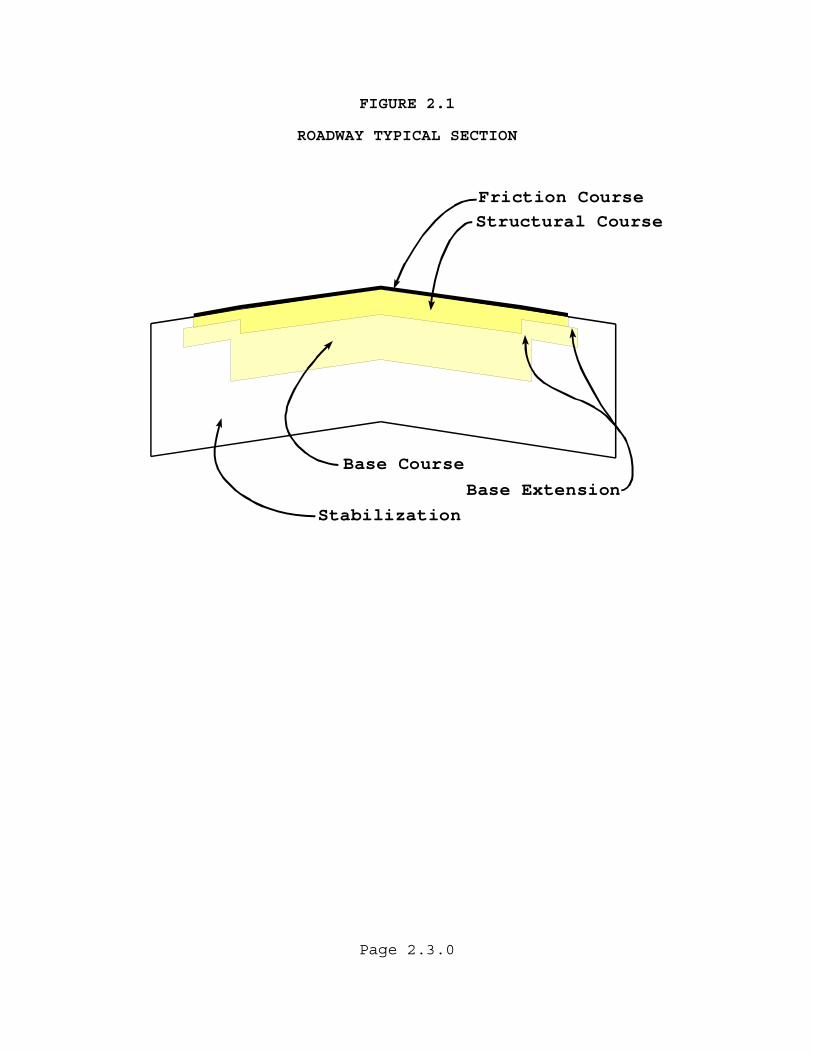
FIGURE 2.1 ROADWAY TYPICAL SECTION
Friction CourseStructural Course
Base Course
StabilizationBase Extension
Page 2.3.0
Page 2.4.0
Composite Base The composite base is a combined granular subbase and asphalt Type B-12.5 that together are bid as an Optional Base Material. Subbase The subbase is a layer of specified material and design thickness that supports the base. This generally is limited to use with a Composite Base. Stabilized Subgrade The stabilized subgrade is a structural layer that is 12"(300 mm) thick. This structural layer serves as a working platform to permit the efficient construction of the base material. It is bid as Type B Stabilization (LBR-40) with the contractor selecting the approved materials necessary to achieve the LBR 40 value. Roadbed Soil The roadbed soil is the natural materials or embankment upon which the Pavement Structure is constructed. 2.2 AASHTO DESIGN EQUATION
The following definitions relate to the AASHTO Design Equation used for calculating pavement thickness. 2.2.1 VARIABLES Accumulated 18-kip (80-kiloNewton) Equivalent Single Axle Loads ESAL or ESALD
The Accumulated 18-kip (80-kiloNewton) Equivalent Single Axle Loads (ESAL) is the traffic load information used for pavement thickness design. The accumulation of the damage caused by mixed truck traffic during a design period is referred to as the ESALD.
Page 2.5.0
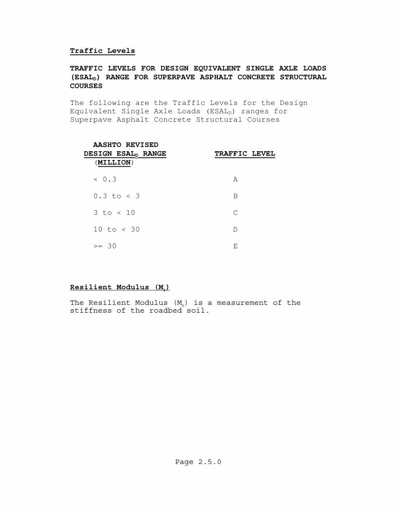
Traffic Levels TRAFFIC LEVELS FOR DESIGN EQUIVALENT SINGLE AXLE LOADS (ESALD) RANGE FOR SUPERPAVE ASPHALT CONCRETE STRUCTURAL COURSES The following are the Traffic Levels for the Design Equivalent Single Axle Loads (ESALD) ranges for Superpave Asphalt Concrete Structural Courses
AASHTO REVISED
DESIGN ESALD RANGE TRAFFIC LEVEL (MILLION)
< 0.3 A
0.3 to < 3 B 3 to < 10 C 10 to < 30 D
>= 30 E
Resilient Modulus (MR) The Resilient Modulus (MR) is a measurement of the stiffness of the roadbed soil.
Page 2.6.0
Reliability (%R) The use of Reliability (%R) permits the Pavement Design Engineer to tailor the design to more closely match the needs of the project. It is the probability of achieving the design life that the Department desires for that facility. The Pavement Design Engineer is cautioned, however, that a high reliability value may increase the asphalt thickness substantially. The models are based on serviceability and not a specific failure mechanism, such as rutting. Recommended values range from 75% to 99% and can be found in Table 5.2. It is important to note that this is not a direct input into the AASHTO Design Equation. The use of a converted value known as the Standard Normal Deviate (ZR) is input into the equation. The reliability value replaces the safety factor that was previously imbedded in the Soil Support Value. Standard Normal Deviate (ZR) The Standard Normal Deviate (ZR) is the corresponding Reliability (%R) value that has been converted into logarithmic form for calculations purposes. 2.2.2 CONSTANTS Standard Deviation (SO) The Standard Deviation (SO) of 0.45 is used in the design calculations to account for variability in traffic load predictions and construction. Present Serviceability Index (PSI) The Present Serviceability Index (PSI) is the ability of a roadway to serve the traffic which uses the facility. A rating of 0 to 5 is used with 5 being the best and 0 being the worst. As road condition decreases due to deterioration, the PSI decreases. Initial Serviceability (PI) The Initial Serviceability (PI) is the condition of a newly constructed roadway. A value of 4.2 is assumed.
Page 2.7.0
Terminal Serviceability (PT) The Terminal Serviceability (PT) is the condition of a road that reaches a point where some type of rehabilitation or reconstruction is warranted. A value of 2.5 is generally assumed. Change In Serviceability (∆PSI) The Change In Serviceability (∆PSI) is the difference between the Initial Serviceability (PI) and Terminal Serviceability (PT). The Department uses a value of 1.7. 2.2.3 UNKNOWNS Required Structural Number (SNR) The Required Structural Number (SNR) is a weighted thickness in inches(millimeters) calculated from traffic load information and roadbed soil stiffness, representing the required strength of the pavement structure. 2.3 TERMS The following terms will be used to describe the Department's design options. New Construction New construction is the complete development of a pavement system on a new alignment. Reconstruction Reconstruction is the complete removal of the friction course, structural course, and base layers along the existing alignment. Some lane additions or alignment changes may occur resulting in the design of additional subgrade. Milling Milling is the controlled removal of existing asphalt pavement by using a rotating drum with teeth which removes the existing material to the desired depth.
Page 2.8.0
Operational Type Projects Operational Type Projects are projects approximately 1000'(300 m) or less that are relatively small such as turn lanes, radius improvements, culvert, replacement, skid hazard, etc. Overlay Overlay is the placement of additional layers of asphalt pavement to remedy functional or structural deficiencies of existing pavement. This is sometimes referred to as resurfacing. Widening Widening includes trench widening, lane addition, and operational type projects. This type of design does not require thickness design calculations. Asphalt Rubber Membrane Interlayer(ARMI) A reflective crack treatment using an asphalt rubber spray application and cover aggregate. Cover aggregate normally use No.6 stone, slag or gravel, so a layer thickness of ½”(10 mm) may be used. No prime nor tack coat is required over the cover aggregate prior to overlaying with initial asphalt lift. ARMI is placed beneath the overlay to resist the stress/strain of reflective cracks and delay the propagation of the crack through the new overlay.
Page 2.9.0
(THIS PAGE HAS BEEN LEFT INTENTIONALLY BLANK)
Page 3.1.0
CHAPTER 3
PAVEMENT THICKNESS DESIGN PROCESS 3.1 DESIGN SOURCE The American Association of State Highway Officials (AASHO) Road Test at Ottawa, Illinois provided the basis for calculating the required pavement thickness. Models were developed that related pavement performance, vehicle loadings, strength of roadbed soils, and the pavement structure. Figure 3.1 is the AASHTO Equation used by the Department for design purposes. The purpose of the AASHTO model in the pavement thickness design process is to calculate the Required Structural Number (SNR). This is the strength of the pavement that must be constructed to carry the mixed vehicle loads over the roadbed soil, while providing satisfactory serviceability during the design period. Knowing the SNR, the pavement layer thickness or overlay thickness can be calculated. Figure 3.2 illustrates the processes. Vehicle loads are expressed in 18-kip (80-kiloNewton) Equivalent Single Axle Loads 18-kip (80-kN) ESAL. This information is normally generated by the District Planning Office and is found in the Project Traffic Forecasting Procedure Topic No. 525-030-120 using the Project Traffic Forecasting Handbook. A simple procedure for estimating 18-kip (80-kN) ESAL's is given in Appendix D. The summation of the 18-kip (80-kN) ESAL's during the design period is referred to as ESALD.
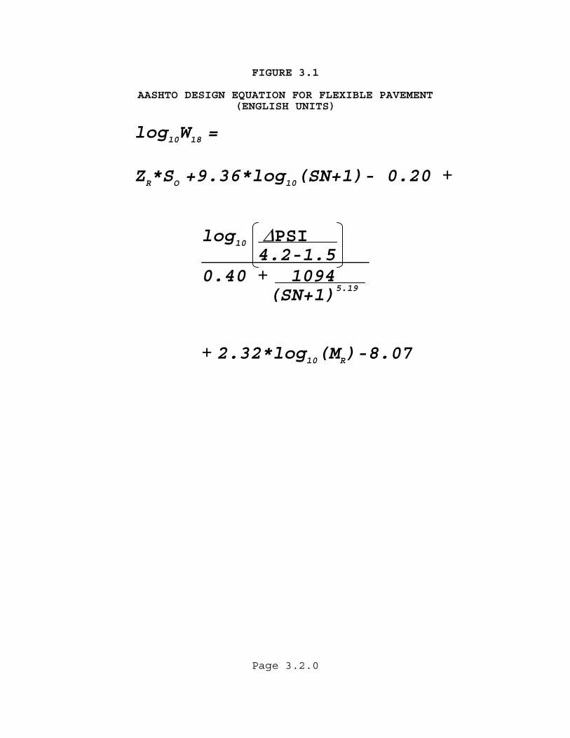
FIGURE 3.1 AASHTO DESIGN EQUATION FOR FLEXIBLE PAVEMENT (ENGLISH UNITS)
log10W18 =
ZR*SO +9.36*log10(SN+1)- 0.20 + log10 ∆PSI 4.2-1.5 0.40 + 1094 (SN+1)5.19
+ 2.32*log10(MR)-8.07
Page 3.2.0
Page 3.3.0
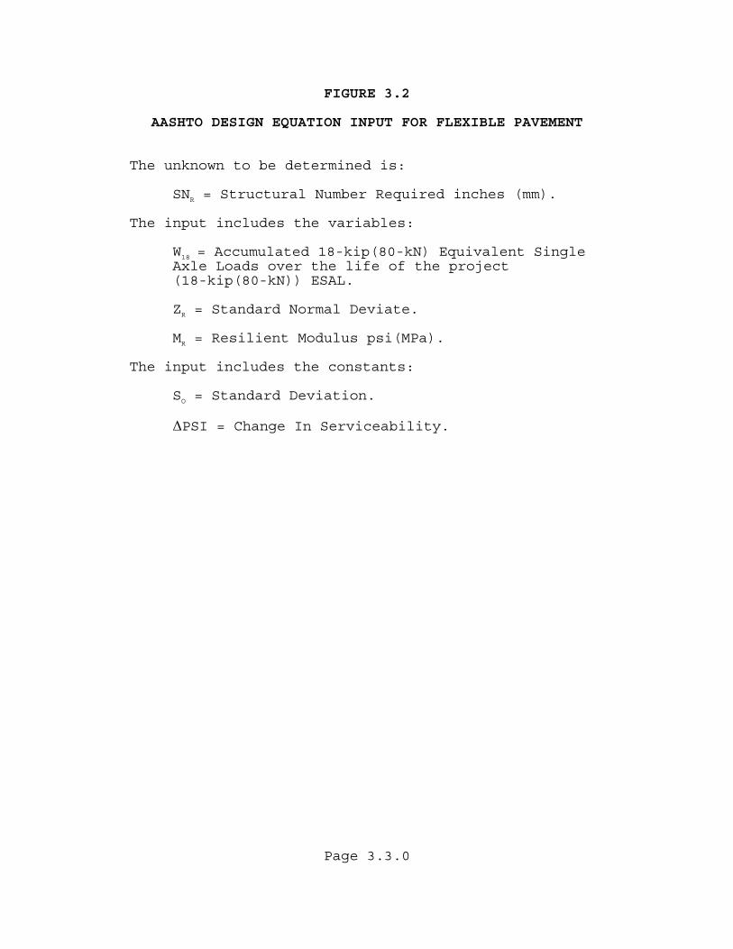
FIGURE 3.2 AASHTO DESIGN EQUATION INPUT FOR FLEXIBLE PAVEMENT The unknown to be determined is:
SNR = Structural Number Required inches (mm). The input includes the variables:
W18 = Accumulated 18-kip(80-kN) Equivalent Single Axle Loads over the life of the project (18-kip(80-kN)) ESAL.
ZR = Standard Normal Deviate.
MR = Resilient Modulus psi(MPa).
The input includes the constants:
SO = Standard Deviation.
∆PSI = Change In Serviceability.
Page 3.4.0
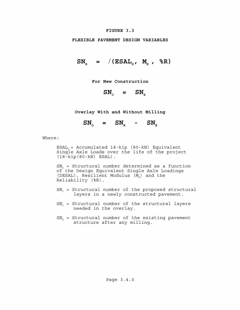
FIGURE 3.3 FLEXIBLE PAVEMENT DESIGN VARIABLES
SNR = /(ESALD, MR , %R) For New Construction
SNC = SNR Overlay With and Without Milling
SNO = SNR - SNE Where: ESALD = Accumulated 18-kip (80-kN) Equivalent Single Axle Loads over the life of the project
(18-kip(80-kN) ESAL).
SNR = Structural number determined as a function of the Design Equivalent Single Axle Loadings (DESAL), Resilient Modulus (MR) and the Reliability (%R).
SNC = Structural number of the proposed structural layers in a newly constructed pavement.
SNO = Structural number of the structural layers needed in the overlay.
SNE = Structural number of the existing pavement structure after any milling.
Page 3.5.0
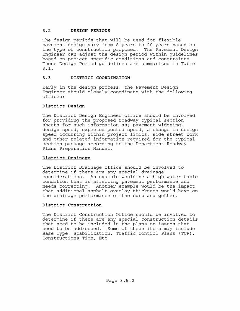
3.2 DESIGN PERIODS The design periods that will be used for flexible pavement design vary from 8 years to 20 years based on the type of construction proposed. The Pavement Design Engineer can adjust the design period within guidelines based on project specific conditions and constraints. These Design Period guidelines are summarized in Table 3.1. 3.3 DISTRICT COORDINATION Early in the design process, the Pavement Design Engineer should closely coordinate with the following offices: District Design The District Design Engineer office should be involved for providing the proposed roadway typical section sheets for such information as; pavement widening, design speed, expected posted speed, a change in design speed occurring within project limits, side street work and other related information required for the typical section package according to the Department Roadway Plans Preparation Manual. District Drainage The District Drainage Office should be involved to determine if there are any special drainage considerations. An example would be a high water table condition that is affecting pavement performance and needs correcting. Another example would be the impact that additional asphalt overlay thickness would have on the drainage performance of the curb and gutter. District Construction The District Construction Office should be involved to determine if there are any special construction details that need to be included in the plans or issues that need to be addressed. Some of these items may include Base Type, Stabilization, Traffic Control Plans (TCP), Constructions Time, Etc.

Page 3.6.0
District Materials The District Materials Office should be involved to determine the availability of suitable materials in the construction area and any other special conditions that may exist. The District Materials Office can also provide recommendations with respect to stabilizing, milling, cross slope correction, and existing pavement condition. Additional coordination of project field reviews and data collection might be needed. The latest Pavement Coring and Evaluations Procedures (Topic No. 675-030-005) can be obtained from the District Materials Office or through the Intranet and DOTNET document library. 3.4 QUALITY The Quality Control of a pavement's design is the Districts responsibility. A written Pavement Design Quality Control Plan should be maintained by the district. Upon completion of the design process, an independent design review needs to be performed. A suggested Pavement Design Quality Control Plan is provided in Appendix B. 3.5 GUIDELINES FOR DESIGN/BUILD PROJECTS The complete pavement design package as part of the design criteria for Design/Build projects may be provided by the Department if sufficient data is available. If the pavement design is not provided by the Department, project specific pavement design criteria may be provided as part of the Design Criteria Package to assure a reasonable pavement design is provided by all competing Design/Build teams.

Page 3.7.0
The project specific pavement design criteria may include the minimum ESALs, minimum design reliability, roadbed resilient modulus, minimum structural asphalt thickness and whether or not modified asphalt binder(PG 76-22) should be used in the final structural layer. For resurfacing designs, a minimum milling depth and whether an ARMI layer is required may be included in the criteria. The Pavement Coring and Evaluation report will normally be provided with the criteria. In addition to project specific criteria, all standard requirements of the Department’s pavement design manuals are to be followed.
TABLE 3.1
DESIGN PERIODS
The Following Design Periods Will Be Used For Flexible Pavement Designs.
New Construction or Reconstruction 20 Years Pavement Overlay Without Milling 8 to 20 Years Pavement Overlay With Milling
Limited Access 12 to 20 Years*
Non-Limited Access 14 to 20 Years* Pavement Overlay of Rigid Pavement 8 to 12 Years Notes * Shorter design periods can be used if there are
constraints such as curb and gutter or scheduled future capacity projects that justify limiting overlay thickness. These reasons should be documented in the pavement design package.

Page 3.8.0
(THIS PAGE HAS BEEN LEFT INTENTIONALLY BLANK)
Page 4.1.0
CHAPTER 4
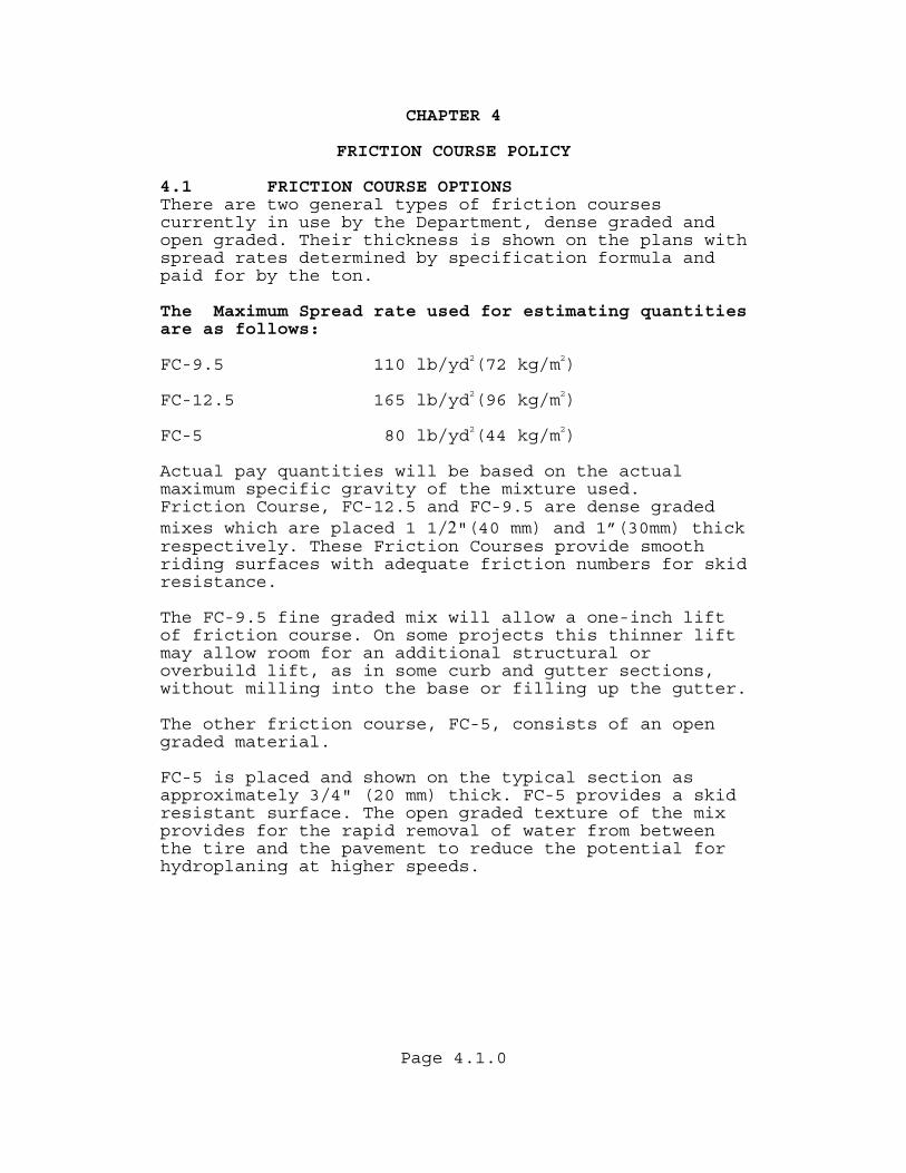
FRICTION COURSE POLICY 4.1 FRICTION COURSE OPTIONS There are two general types of friction courses currently in use by the Department, dense graded and open graded. Their thickness is shown on the plans with spread rates determined by specification formula and paid for by the ton. The Maximum Spread rate used for estimating quantities are as follows:
FC-9.5 110 lb/yd2(72 kg/m2) FC-12.5 165 lb/yd2(96 kg/m2) FC-5 80 lb/yd2(44 kg/m2) Actual pay quantities will be based on the actual maximum specific gravity of the mixture used. Friction Course, FC-12.5 and FC-9.5 are dense graded mixes which are placed 1 1/2"(40 mm) and 1”(30mm) thick respectively. These Friction Courses provide smooth riding surfaces with adequate friction numbers for skid resistance. The FC-9.5 fine graded mix will allow a one-inch lift of friction course. On some projects this thinner lift may allow room for an additional structural or overbuild lift, as in some curb and gutter sections, without milling into the base or filling up the gutter. The other friction course, FC-5, consists of an open graded material. FC-5 is placed and shown on the typical section as approximately 3/4" (20 mm) thick. FC-5 provides a skid resistant surface. The open graded texture of the mix provides for the rapid removal of water from between the tire and the pavement to reduce the potential for hydroplaning at higher speeds.
Page 4.2.0
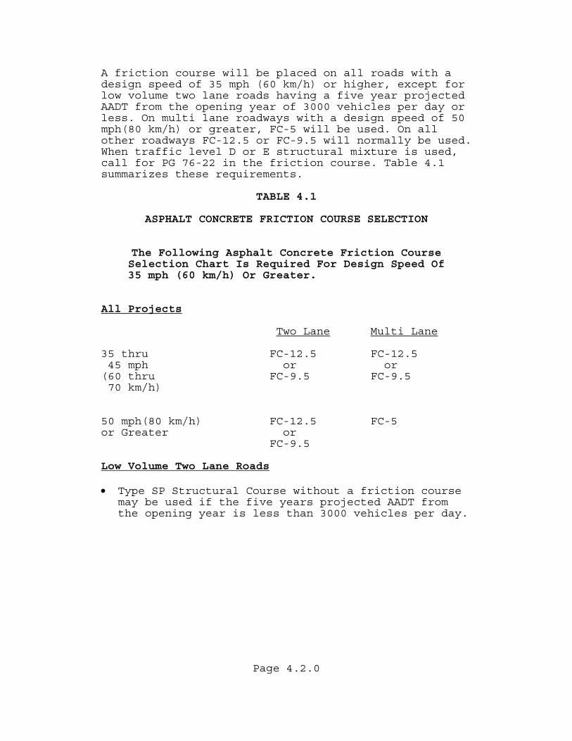
A friction course will be placed on all roads with a design speed of 35 mph (60 km/h) or higher, except for low volume two lane roads having a five year projected AADT from the opening year of 3000 vehicles per day or less. On multi lane roadways with a design speed of 50 mph(80 km/h) or greater, FC-5 will be used. On all other roadways FC-12.5 or FC-9.5 will normally be used. When traffic level D or E structural mixture is used, call for PG 76-22 in the friction course. Table 4.1 summarizes these requirements. TABLE 4.1 ASPHALT CONCRETE FRICTION COURSE SELECTION
The Following Asphalt Concrete Friction Course Selection Chart Is Required For Design Speed Of
35 mph (60 km/h) Or Greater. All Projects
Two Lane Multi Lane 35 thru FC-12.5 FC-12.5 45 mph or or (60 thru FC-9.5 FC-9.5 70 km/h) 50 mph(80 km/h) FC-12.5 FC-5 or Greater or FC-9.5 Low Volume Two Lane Roads • Type SP Structural Course without a friction course
may be used if the five years projected AADT from the opening year is less than 3000 vehicles per day.
Page 4.3.0
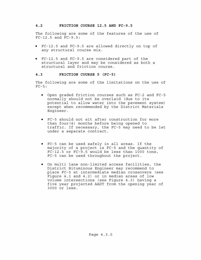
4.2 FRICTION COURSE 12.5 AND FC-9.5 The following are some of the features of the use of FC-12.5 and FC-9.5: • FC-12.5 and FC-9.5 are allowed directly on top of
any structural course mix. • FC-12.5 and FC-9.5 are considered part of the
structural layer and may be considered as both a structural and friction course.
4.3 FRICTION COURSE 5 (FC-5) The following are some of the limitations on the use of FC-5:
• Open graded friction courses such as FC-2 and FC-5 normally should not be overlaid (due to its potential to allow water into the pavement system) except when recommended by the District Materials Engineer.
• FC-5 should not sit after construction for more
than four(4) months before being opened to traffic. If necessary, the FC-5 may need to be let under a separate contract.
• FC-5 can be used safely in all areas. If the
majority of a project is FC-5 and the quantity of FC-12.5 or FC–9.5 would be less than 1000 tons, FC-5 can be used throughout the project.
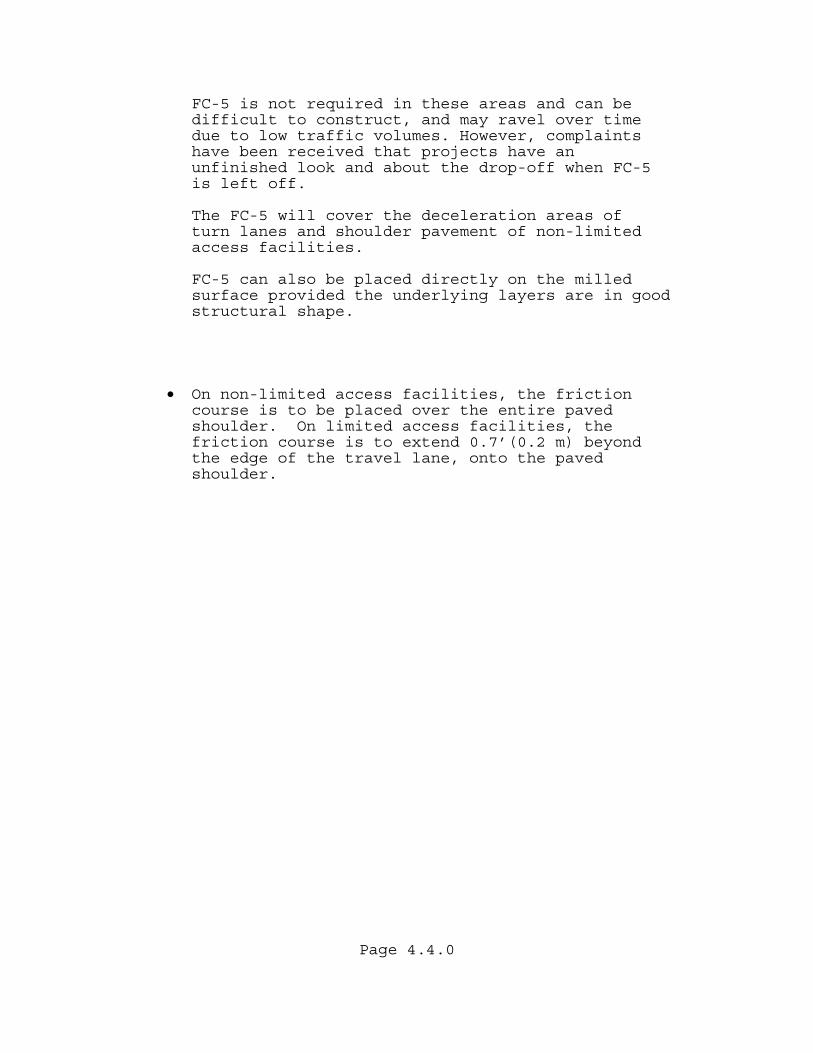
• On multi lane non-limited access facilities, the
District Bituminous Engineer may recommend to place FC-5 at intermediate median crossovers (see Figure 4.1 and 4.2) or in median areas of low volume intersections (see Figure 4.3) having a five year projected AADT from the opening year of 3000 or less.
Page 4.4.0
FC-5 is not required in these areas and can be difficult to construct, and may ravel over time due to low traffic volumes. However, complaints have been received that projects have an unfinished look and about the drop-off when FC-5 is left off.
The FC-5 will cover the deceleration areas of
turn lanes and shoulder pavement of non-limited access facilities.
FC-5 can also be placed directly on the milled
surface provided the underlying layers are in good structural shape.
• On non-limited access facilities, the friction course is to be placed over the entire paved shoulder. On limited access facilities, the friction course is to extend 0.7’(0.2 m) beyond the edge of the travel lane, onto the paved shoulder.
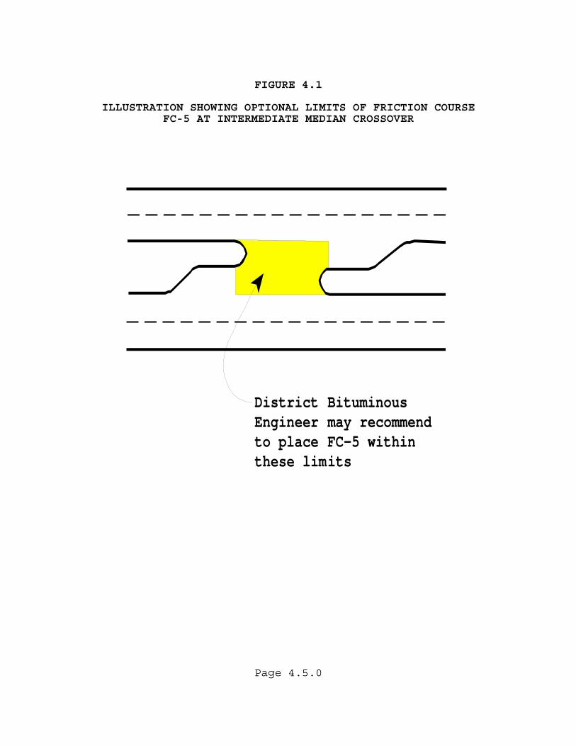
FIGURE 4.1
ILLUSTRATION SHOWING OPTIONAL LIMITS OF FRICTION COURSE FC-5 AT INTERMEDIATE MEDIAN CROSSOVER
District BituminousEngineer may recommendto place FC-5 withinthese limits
Page 4.5.0
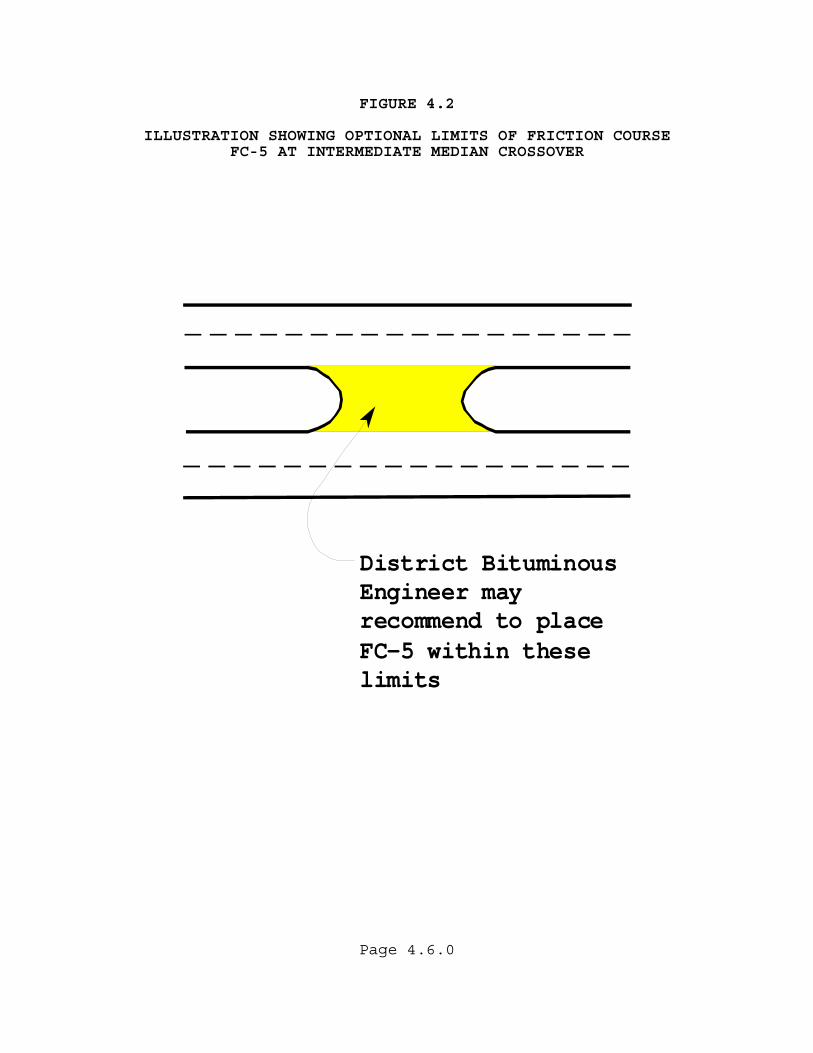
FIGURE 4.2
ILLUSTRATION SHOWING OPTIONAL LIMITS OF FRICTION COURSE FC-5 AT INTERMEDIATE MEDIAN CROSSOVER
District BituminousEngineer mayrecommend to placeFC-5 within theselimits
Page 4.6.0
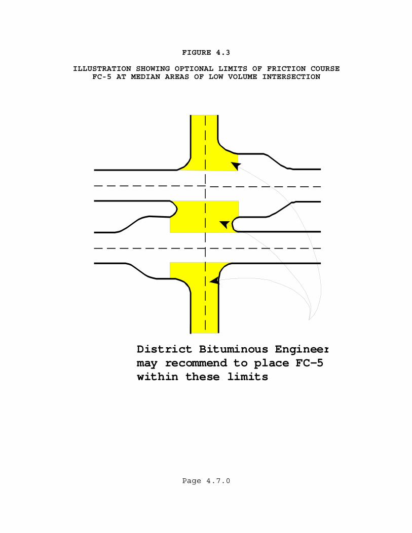
FIGURE 4.3
ILLUSTRATION SHOWING OPTIONAL LIMITS OF FRICTION COURSE FC-5 AT MEDIAN AREAS OF LOW VOLUME INTERSECTION
District Bituminous Engineermay recommend to place FC-5within these limits
Page 4.7.0

Page 4.8.0
(THIS PAGE HAS BEEN LEFT INTENTIONALLY BLANK)
Page 5.1.0
CHAPTER 5 PAVEMENT THICKNESS DESIGN PROCESS FOR NEW CONSTRUCTION 5.1 OVERVIEW This process is applicable to new construction or total reconstruction projects in Florida where the Pavement Design Engineer must calculate the pavement layer thickness using the AASHTO Procedure. For new lane additions, short pavement sections (approximately 1000'(300 m) or less) such as bridge replacement, cross roads, short turnouts, etc., the principles provided in Chapter 7 of this manual shall apply. 5.2 REQUIRED STRUCTURAL NUMBER (SNR) CALCULATIONS
USING THE AASHTO DESIGN GUIDE The following is a summary of the steps to be taken to solve for the Required Structural Number (SNR):
• The 18-kip(80-kilonewton) Equivalent Single Axle Loads 18-kip(80-kN) ESAL's are obtained from the District Planning Office. This process can be found in the Project Traffic Forecasting Handbook Procedure Topic No. 525-030-120 using the Project Traffic Forecasting Handbook. Appendix D provides a simple procedure for calculating the accumulated 18-kip(80-kN) ESAL's or ESALD for the appropriate design period.
• The Resilient Modulus (MR) used to characterize
the strength of the roadbed soil is obtained from the State Materials Office, or from the District Materials Office using either actual laboratory testing or the Design Limerock Bearing Ratio (LBR) value which is based on 90% of the anticipated LBR's exceeding the Design LBR. This process is discussed in the next section. The relationship between the Design Limerock Bearing Ratio (LBR) and Resilient Modulus (MR) is shown in Figure 5.1 with example values in Table 5.1.
Page 5.2.0
• A safety factor is applied using a Reliability (%R) value from Table 5.2. Recommended values range from 75 to 99%. A Standard Deviation (SO) of 0.45 is used in the calculation. The Standard Normal Deviate (ZR) is dependent on the Reliability (%R).
Using these values, the Pavement Design Engineer will calculate the Structural Number Required (SNR) using the design tables in Appendix A., or AASHTOWare DARWin Pavement Design and Analysis System computer program. Each design table uses a different Reliability (%R) and relates Design 18-kip (80-kilonewton) Equivalent Single Axle Loads (ESALD) to the Structural Number Required (SNR) for multiple Resilient Modulus (MR) values. A design table example is provided using Table 5.3. 5.2.1 DESIGN EXAMPLE The following is an example illustrating the mechanics of this procedure. Using the following input for New Construction of an Urban Arterial:
ESALD = 4 900 000 (from the Planning Office) Use 5 000 000
MR = 14,000 psi (95 MPa) (from the State Materials Office)
%R = 80 to 90 (choose %R = 90 from Table 5.2)
Design 18-kip (80-kilonewton) Equivalent Single Axle Loads (ESALD) and Resilient Modulus (MR) values can generally be rounded up or down to the nearest table values. Final thickness designs are to the nearest ½"(10 mm) of structural course. If desired, an interpolated SNR value can be used. The solution is:
SNR = 3.57"(91 mm) (from Table 5.3)
Page 5.3.0
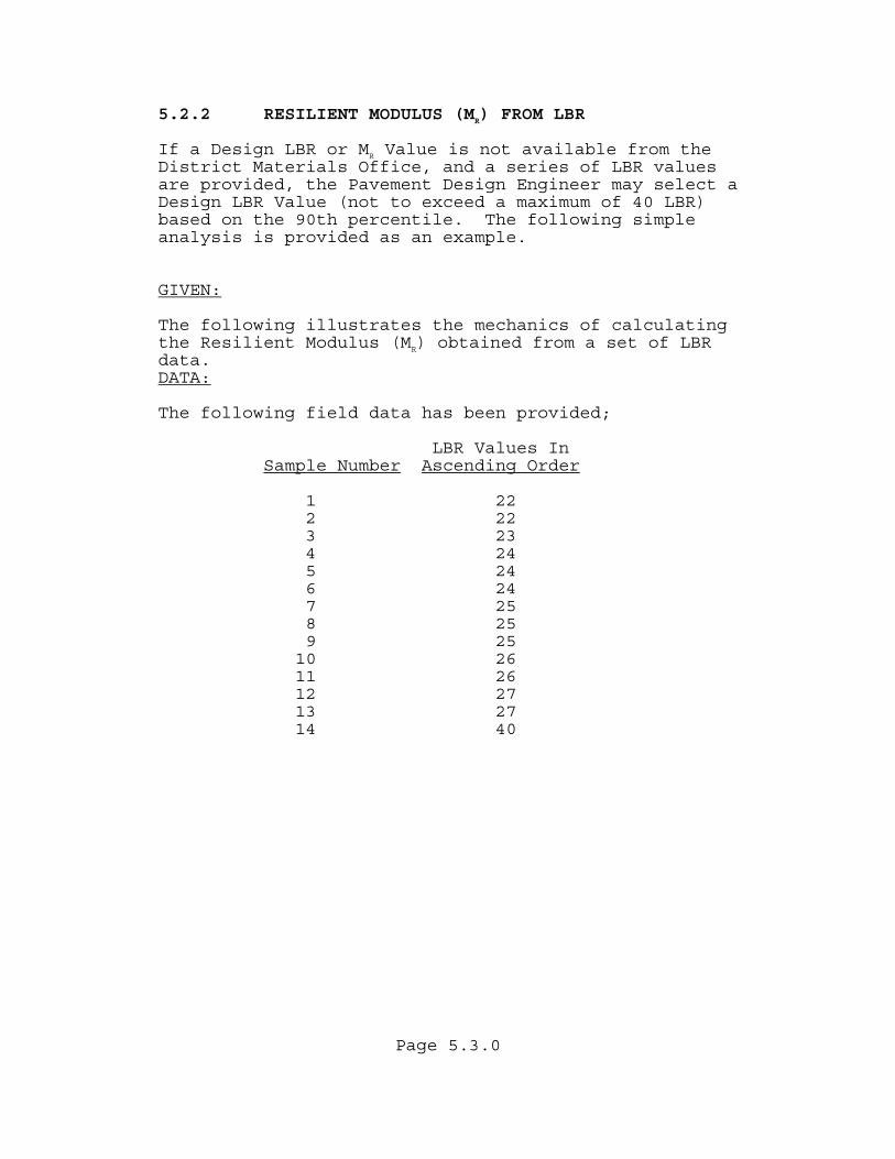
5.2.2 RESILIENT MODULUS (MR) FROM LBR If a Design LBR or MR Value is not available from the District Materials Office, and a series of LBR values are provided, the Pavement Design Engineer may select a Design LBR Value (not to exceed a maximum of 40 LBR) based on the 90th percentile. The following simple analysis is provided as an example. GIVEN: The following illustrates the mechanics of calculating the Resilient Modulus (MR) obtained from a set of LBR data. DATA: The following field data has been provided;
LBR Values In Sample Number Ascending Order
1 22 2 22 3 23 4 24 5 24 6 24 7 25 8 25 9 25 10 26 11 26 12 27 13 27 14 40
Page 5.4.0
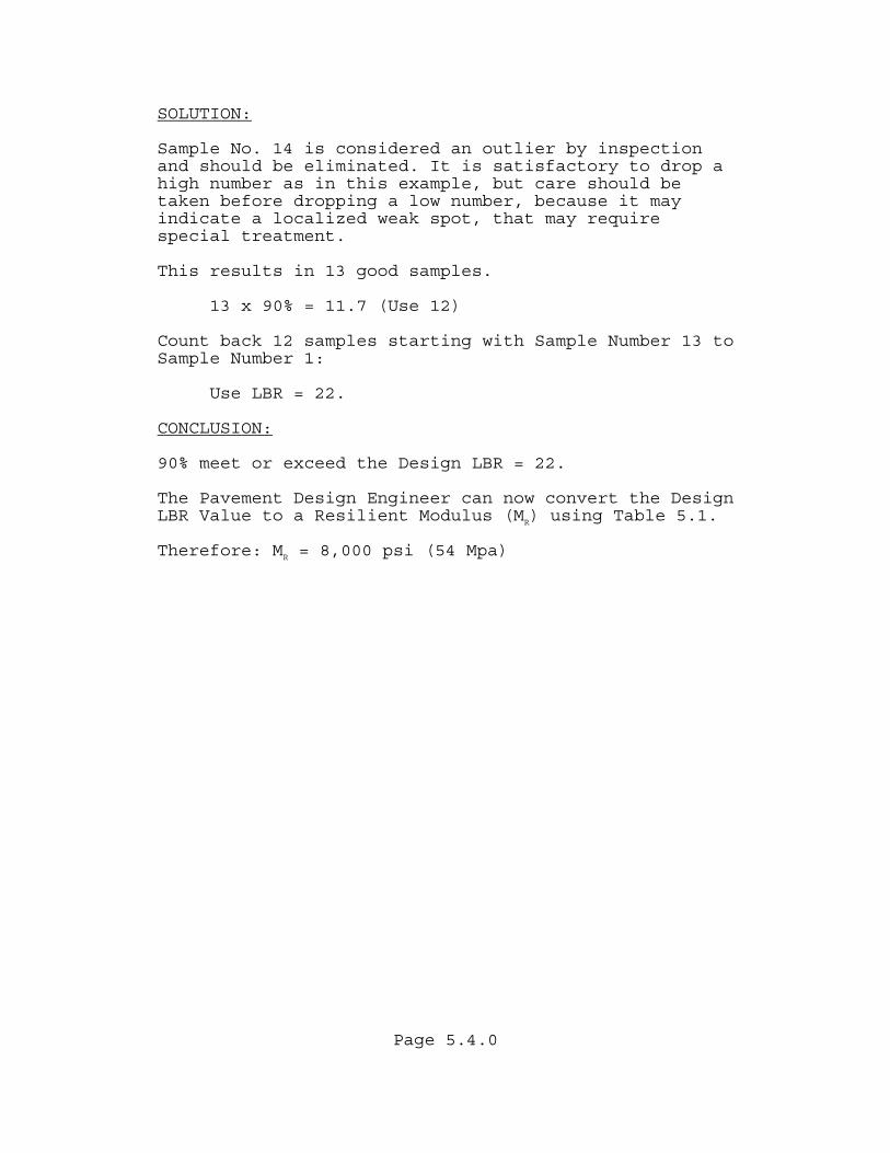
SOLUTION: Sample No. 14 is considered an outlier by inspection and should be eliminated. It is satisfactory to drop a high number as in this example, but care should be taken before dropping a low number, because it may indicate a localized weak spot, that may require special treatment. This results in 13 good samples.
13 x 90% = 11.7 (Use 12) Count back 12 samples starting with Sample Number 13 to Sample Number 1:
Use LBR = 22. CONCLUSION: 90% meet or exceed the Design LBR = 22. The Pavement Design Engineer can now convert the Design LBR Value to a Resilient Modulus (MR) using Table 5.1. Therefore: MR = 8,000 psi (54 Mpa)
Page 5.5.0
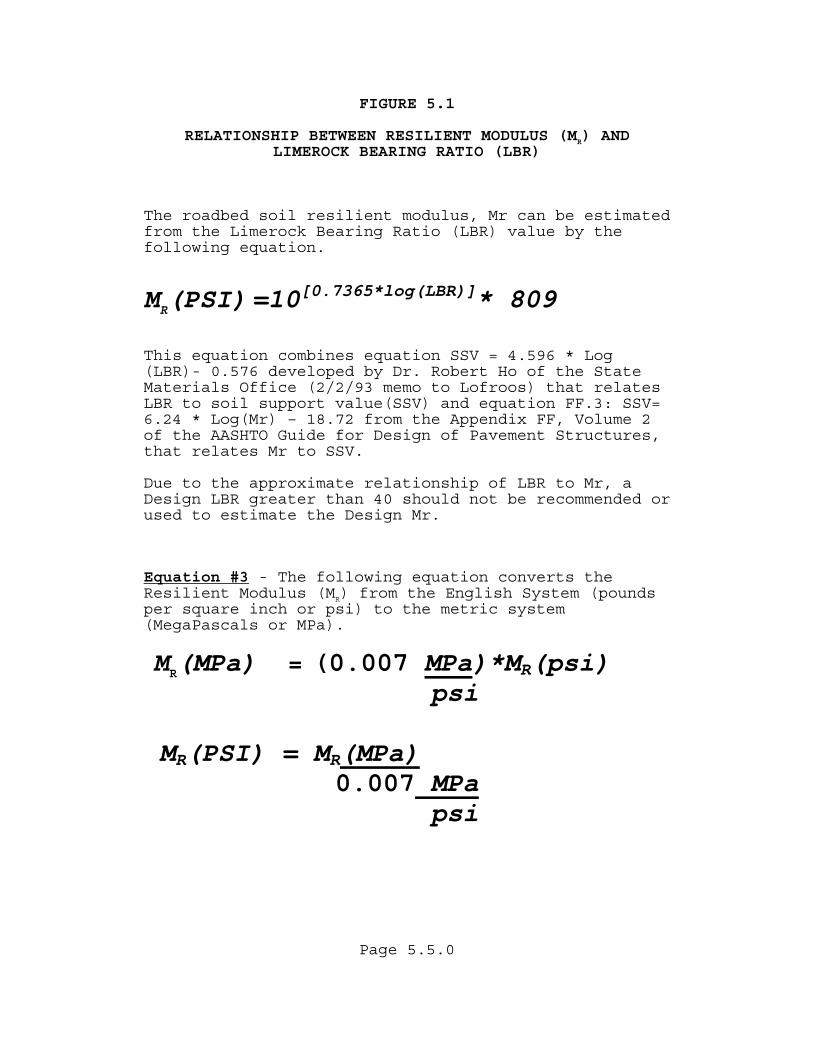
FIGURE 5.1 RELATIONSHIP BETWEEN RESILIENT MODULUS (MR) AND LIMEROCK BEARING RATIO (LBR)
The roadbed soil resilient modulus, Mr can be estimated from the Limerock Bearing Ratio (LBR) value by the following equation.
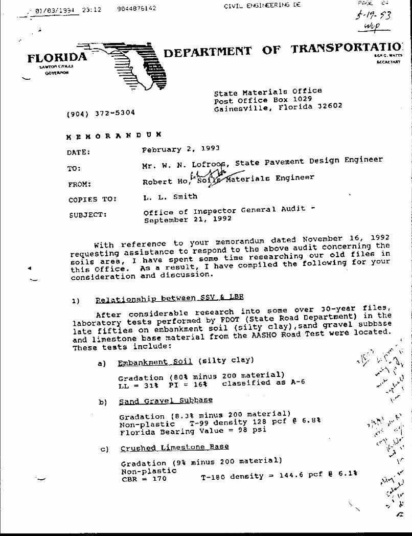
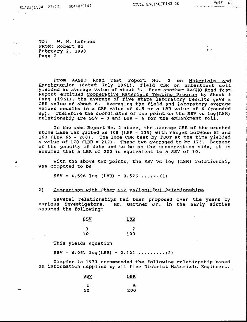
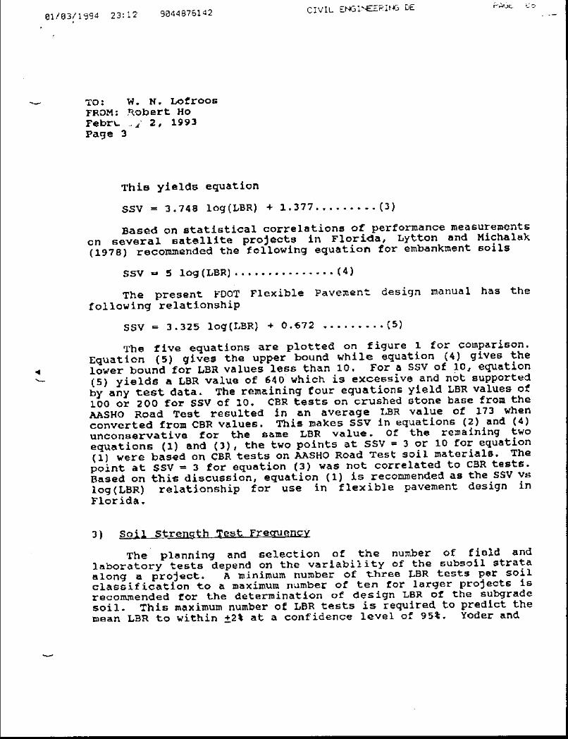
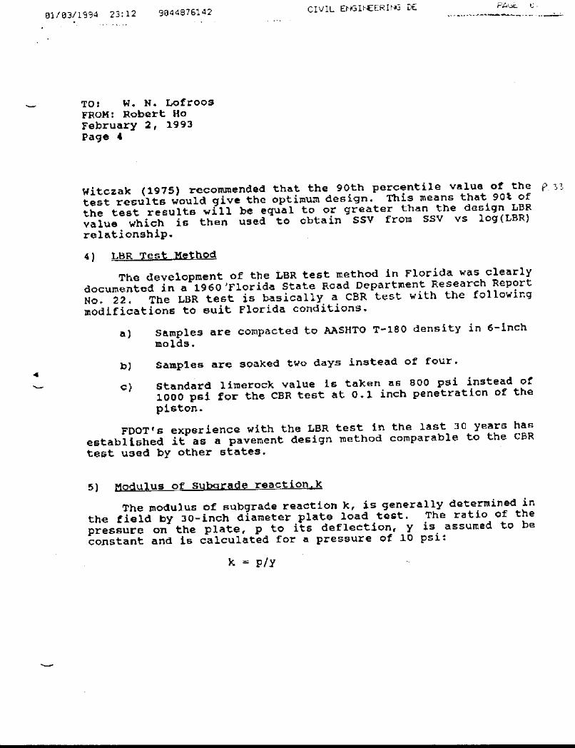
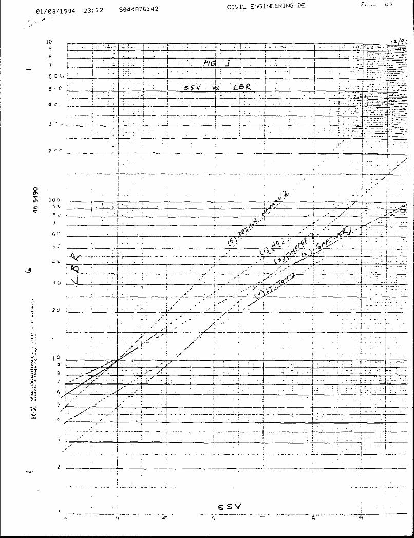
MR(PSI) =10[0.7365*log(LBR)]* 809 This equation combines equation SSV = 4.596 * Log (LBR)- 0.576 developed by Dr. Robert Ho of the State Materials Office (2/2/93 memo to Lofroos) that relates LBR to soil support value(SSV) and equation FF.3: SSV= 6.24 * Log(Mr) – 18.72 from the Appendix FF, Volume 2 of the AASHTO Guide for Design of Pavement Structures, that relates Mr to SSV. Due to the approximate relationship of LBR to Mr, a Design LBR greater than 40 should not be recommended or used to estimate the Design Mr.
Equation #3 - The following equation converts the Resilient Modulus (MR) from the English System (pounds per square inch or psi) to the metric system (MegaPascals or MPa).
MR(MPa) = (0.007 MPa)*MR(psi) psi
MR(PSI) = MR(MPa) 0.007 MPa psi
Page 5.6.0
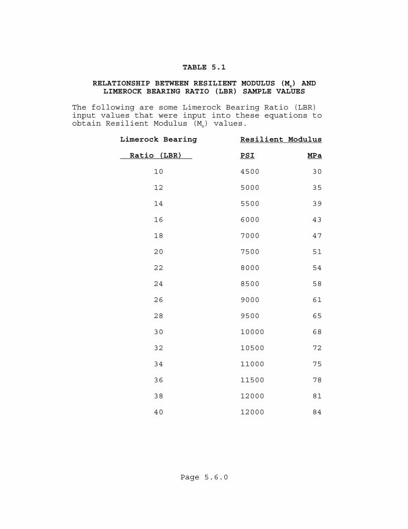
TABLE 5.1 RELATIONSHIP BETWEEN RESILIENT MODULUS (MR) AND LIMEROCK BEARING RATIO (LBR) SAMPLE VALUES The following are some Limerock Bearing Ratio (LBR) input values that were input into these equations to obtain Resilient Modulus (MR) values.
Limerock Bearing Resilient Modulus
Ratio (LBR) PSI MPa
10 4500 30
12 5000 35 14 5500 39 16 6000 43 18 7000 47 20 7500 51 22 8000 54 24 8500 58 26 9000 61 28 9500 65 30 10000 68 32 10500 72 34 11000 75 36 11500 78 38 12000 81 40 12000 84
Page 5.7.0
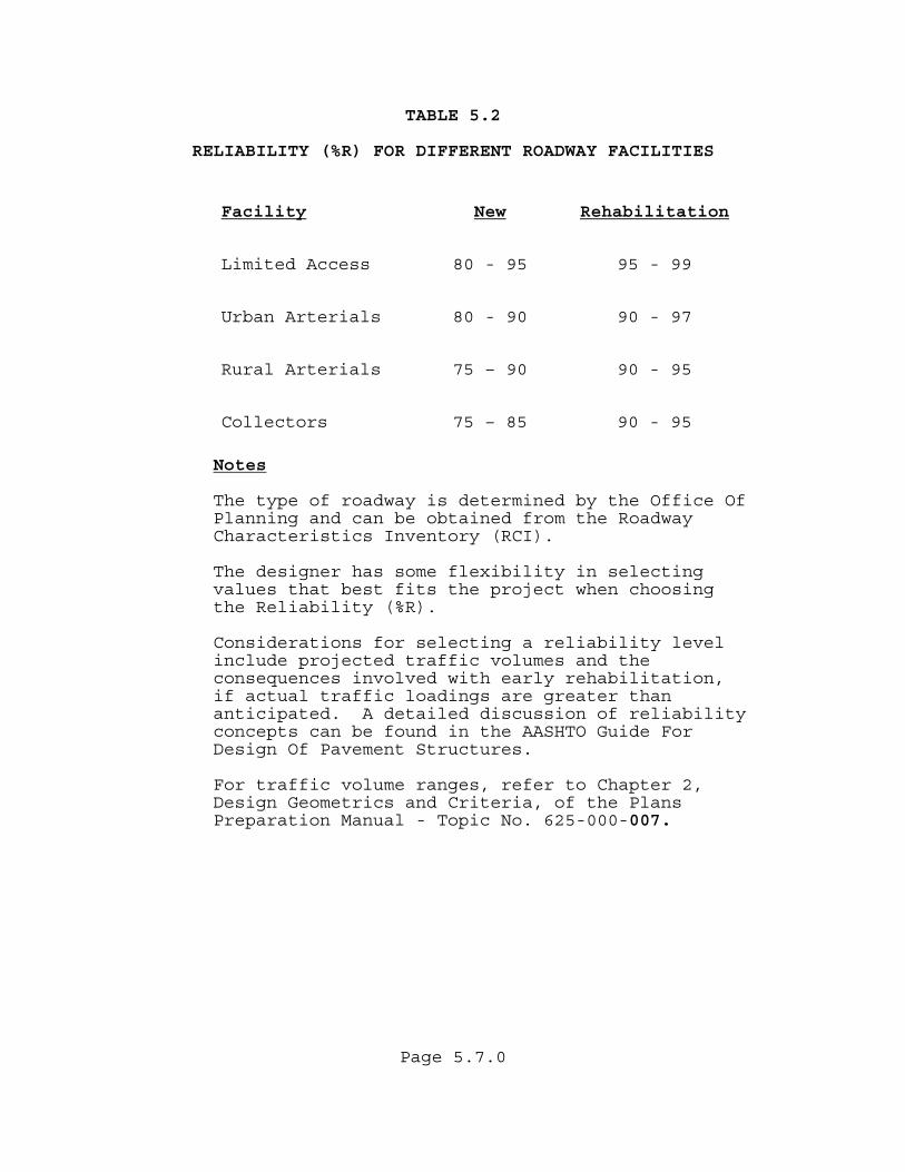
TABLE 5.2 RELIABILITY (%R) FOR DIFFERENT ROADWAY FACILITIES
Facility New Rehabilitation
Limited Access 80 - 95 95 - 99
Urban Arterials 80 - 90 90 - 97
Rural Arterials 75 – 90 90 - 95
Collectors 75 – 85 90 - 95
Notes
The type of roadway is determined by the Office Of Planning and can be obtained from the Roadway Characteristics Inventory (RCI).
The designer has some flexibility in selecting values that best fits the project when choosing the Reliability (%R).
Considerations for selecting a reliability level include projected traffic volumes and the consequences involved with early rehabilitation, if actual traffic loadings are greater than anticipated. A detailed discussion of reliability concepts can be found in the AASHTO Guide For Design Of Pavement Structures. For traffic volume ranges, refer to Chapter 2, Design Geometrics and Criteria, of the Plans Preparation Manual - Topic No. 625-000-007.

Page 5.8.0
TABLE 5.3
REQUIRED STRUCTURAL NUMBER (SNR) 90% RELIABILITY (%R)
RESILIENT MODULUS (MR) RANGE 4,000 PSI TO 18,000 PSI
RESILIENT MODULUS (MR), (PSI x 1000) ESALD 4 5 6 7 8 9 10 11 12 13 14 15 16 17 18 100 000 3.02 2.77 2.59 2.44 2.31 2.21 2.12 2.04 1.97 1.91 1.86 1.81 1.76 1.72 1.68 150 000 3.23 2.97 2.77 2.61 2.47 2.36 2.27 2.19 2.11 2.05 1.99 1.94 1.89 1.84 1.80 200 000 3.39 3.11 2.90 2.73 2.60 2.48 2.38 2.30 2.22 2.15 2.09 2.03 1.98 1.94 1.89 250 000 3.52 3.23 3.01 2.84 2.69 2.57 2.47 2.38 2.30 2.23 2.17 2.11 2.06 2.01 1.97 300 000 3.62 3.33 3.10 2.92 2.78 2.65 2.55 2.46 2.37 2.30 2.24 2.18 2.12 2.07 2.03 350 000 3.71 3.41 3.18 3.00 2.85 2.72 2.61 2.52 2.44 2.36 2.30 2.23 2.18 2.13 2.08 400 000 3.79 3.49 3.25 3.07 2.91 2.78 2.67 2.58 2.49 2.42 2.35 2.29 2.23 2.18 2.13 450 000 3.87 3.56 3.32 3.13 2.97 2.84 2.73 2.63 2.54 2.46 2.39 2.33 2.27 2.22 2.17 500 000 3.93 3.62 3.38 3.18 3.02 2.89 2.77 2.67 2.59 2.51 2.44 2.37 2.31 2.26 2.21 600 000 4.05 3.73 3.48 3.28 3.12 2.98 2.86 2.76 2.67 2.58 2.51 2.45 2.39 2.33 2.28 700 000 4.14 3.82 3.57 3.36 3.20 3.05 2.93 2.83 2.73 2.65 2.58 2.51 2.45 2.39 2.34 800 000 4.23 3.90 3.64 3.44 3.27 3.12 3.00 2.89 2.80 2.71 2.63 2.57 2.50 2.44 2.39 900 000 4.31 3.97 3.71 3.51 3.33 3.18 3.06 2.95 2.85 2.76 2.69 2.62 2.55 2.49 2.44 1 000 000 4.38 4.04 3.78 3.57 3.39 3.24 3.11 3.00 2.90 2.81 2.73 2.66 2.60 2.54 2.48 1 500 000 4.65 4.30 4.03 3.81 3.62 3.46 3.33 3.21 3.10 3.01 2.92 2.85 2.78 2.71 2.65 2 000 000 4.85 4.50 4.21 3.99 3.79 3.63 3.49 3.36 3.25 3.16 3.07 2.99 2.91 2.85 2.78 2 500 000 5.01 4.65 4.36 4.13 3.93 3.76 3.62 3.49 3.38 3.27 3.18 3.10 3.02 2.95 2.89 3 000 000 5.14 4.77 4.48 4.25 4.05 3.88 3.73 3.60 3.48 3.37 3.28 3.19 3.12 3.04 2.98 3 500 000 5.25 4.88 4.59 4.35 4.14 3.97 3.82 3.69 3.57 3.46 3.36 3.28 3.20 3.12 3.06 4 000 000 5.35 4.98 4.68 4.44 4.23 4.06 3.90 3.77 3.65 3.54 3.44 3.35 3.27 3.19 3.12 4 500 000 5.44 5.06 4.76 4.52 4.31 4.13 3.98 3.84 3.72 3.61 3.51 3.42 3.33 3.26 3.19 5 000 000 5.52 5.14 4.83 4.59 4.38 4.20 4.04 3.90 3.78 3.67 3.57 3.47 3.39 3.31 3.24 6 000 000 5.66 5.27 4.96 4.71 4.50 4.32 4.16 4.02 3.89 3.78 3.67 3.58 3.49 3.41 3.34 7 000 000 5.78 5.38 5.07 4.82 4.61 4.42 4.26 4.12 3.99 3.87 3.77 3.67 3.58 3.50 3.43 8 000 000 5.88 5.48 5.17 4.91 4.70 4.51 4.35 4.20 4.07 3.95 3.85 3.75 3.66 3.58 3.50 9 000 000 5.97 5.57 5.26 5.00 4.78 4.59 4.43 4.28 4.15 4.03 3.92 3.82 3.73 3.65 3.57 10 000 000 6.06 5.65 5.33 5.07 4.85 4.66 4.50 4.35 4.22 4.10 3.99 3.89 3.79 3.71 3.63 15 000 000 6.39 5.97 5.64 5.37 5.14 4.95 4.77 4.62 4.48 4.36 4.25 4.14 4.05 3.96 3.88 20 000 000 6.63 6.20 5.86 5.59 5.35 5.15 4.98 4.82 4.68 4.55 4.44 4.33 4.23 4.14 4.06 25 000 000 6.82 6.38 6.04 5.76 5.52 5.32 5.14 4.98 4.84 4.71 4.59 4.48 4.38 4.29 4.20 30 000 000 6.98 6.53 6.18 5.90 5.66 5.45 5.27 5.11 4.96 4.83 4.71 4.60 4.50 4.41 4.32 35 000 000 7.12 6.66 6.31 6.02 5.78 5.57 5.38 5.22 5.07 4.94 4.82 4.71 4.61 4.51 4.42 40 000 000 7.24 6.78 6.42 6.13 5.88 5.67 5.48 5.32 5.17 5.04 4.91 4.80 4.70 4.60 4.51 45 000 000 7.34 6.88 6.52 6.22 5.97 5.76 5.57 5.41 5.26 5.12 5.00 4.88 4.78 4.68 4.59 50 000 000 7.44 6.97 6.61 6.31 6.06 5.84 5.65 5.49 5.34 5.20 5.07 4.96 4.85 4.76 4.66 60 000 000 7.61 7.13 6.76 6.46 6.21 5.99 5.79 5.62 5.47 5.33 5.21 5.09 4.98 4.88 4.79 70 000 000 7.76 7.27 6.90 6.59 6.33 6.11 5.91 5.74 5.59 5.45 5.32 5.20 5.09 4.99 4.90 80 000 000 7.88 7.40 7.01 6.70 6.44 6.22 6.02 5.85 5.69 5.55 5.42 5.30 5.19 5.09 4.99 90 000 000 8.00 7.51 7.12 6.80 6.54 6.31 6.11 5.94 5.78 5.64 5.51 5.39 5.28 5.17 5.08 100 000 000 8.10 7.60 7.21 6.90 6.63 6.40 6.20 6.02 5.86 5.72 5.59 5.47 5.35 5.25 5.15
Page 5.9.0
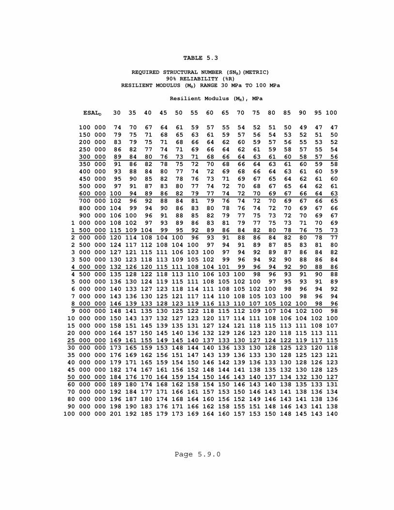
TABLE 5.3
REQUIRED STRUCTURAL NUMBER (SN )(METRIC) R
90% RELIABILITY (%R) RESILIENT MODULUS (MR) RANGE 30 MPa TO 100 MPa
Resilient Modulus (MR), MPa
ESALD 30 35 40 45 50 55 60 65 70 75 80 85 90 95 100
100 000 74 70 67 64 61 59 57 55 54 52 51 50 49 47 47 150 000 79 75 71 68 65 63 61 59 57 56 54 53 52 51 50 200 000 83 79 75 71 68 66 64 62 60 59 57 56 55 53 52 250 000 86 82 77 74 71 69 66 64 62 61 59 58 57 55 54 300 000 89 84 80 76 73 71 68 66 64 63 61 60 58 57 56 350 000 91 86 82 78 75 72 70 68 66 64 63 61 60 59 58 400 000 93 88 84 80 77 74 72 69 68 66 64 63 61 60 59 450 000 95 90 85 82 78 76 73 71 69 67 65 64 62 61 60 500 000 97 91 87 83 80 77 74 72 70 68 67 65 64 62 61 600 000 100 94 89 86 82 79 77 74 72 70 69 67 66 64 63 700 000 102 96 92 88 84 81 79 76 74 72 70 69 67 66 65 800 000 104 99 94 90 86 83 80 78 76 74 72 70 69 67 66 900 000 106 100 96 91 88 85 82 79 77 75 73 72 70 69 67 1 000 000 108 102 97 93 89 86 83 81 79 77 75 73 71 70 69 1 500 000 115 109 104 99 95 92 89 86 84 82 80 78 76 75 73 2 000 000 120 114 108 104 100 96 93 91 88 86 84 82 80 78 77 2 500 000 124 117 112 108 104 100 97 94 91 89 87 85 83 81 80 3 000 000 127 121 115 111 106 103 100 97 94 92 89 87 86 84 82 3 500 000 130 123 118 113 109 105 102 99 96 94 92 90 88 86 84 4 000 000 132 126 120 115 111 108 104 101 99 96 94 92 90 88 86 4 500 000 135 128 122 118 113 110 106 103 100 98 96 93 91 90 88 5 000 000 136 130 124 119 115 111 108 105 102 100 97 95 93 91 89 6 000 000 140 133 127 123 118 114 111 108 105 102 100 98 96 94 92 7 000 000 143 136 130 125 121 117 114 110 108 105 103 100 98 96 94 8 000 000 146 139 133 128 123 119 116 113 110 107 105 102 100 98 96 9 000 000 148 141 135 130 125 122 118 115 112 109 107 104 102 100 98 10 000 000 150 143 137 132 127 123 120 117 114 111 108 106 104 102 100 15 000 000 158 151 145 139 135 131 127 124 121 118 115 113 111 108 107 20 000 000 164 157 150 145 140 136 132 129 126 123 120 118 115 113 111 25 000 000 169 161 155 149 145 140 137 133 130 127 124 122 119 117 115 30 000 000 173 165 159 153 148 144 140 136 133 130 128 125 123 120 118 35 000 000 176 169 162 156 151 147 143 139 136 133 130 128 125 123 121 40 000 000 179 171 165 159 154 150 146 142 139 136 133 130 128 126 123 45 000 000 182 174 167 161 156 152 148 144 141 138 135 132 130 128 125 50 000 000 184 176 170 164 159 154 150 146 143 140 137 134 132 130 127 60 000 000 189 180 174 168 162 158 154 150 146 143 140 138 135 133 131 70 000 000 192 184 177 171 166 161 157 153 150 146 143 141 138 136 134 80 000 000 196 187 180 174 168 164 160 156 152 149 146 143 141 138 136 90 000 000 198 190 183 176 171 166 162 158 155 151 148 146 143 141 138 100 000 000 201 192 185 179 173 169 164 160 157 153 150 148 145 143 140
Page 5.10.0
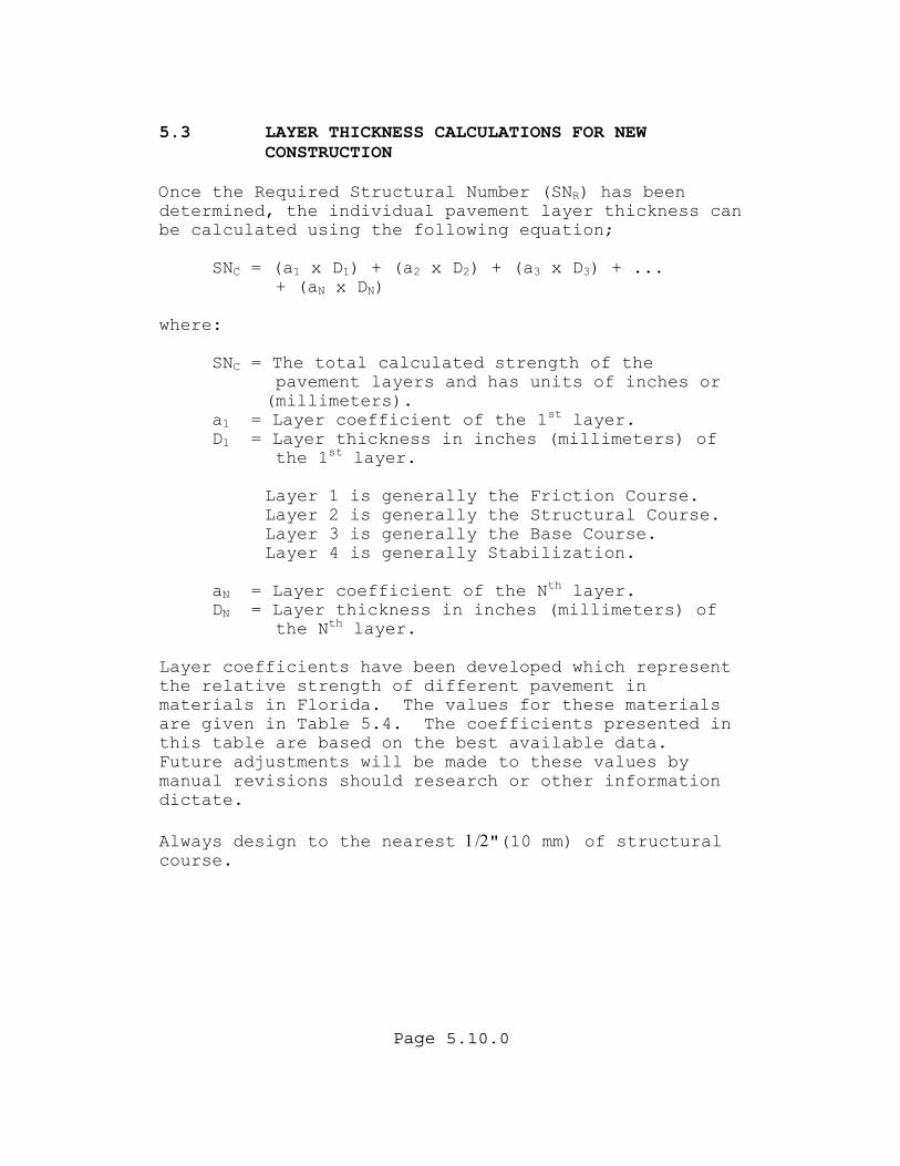
5.3 LAYER THICKNESS CALCULATIONS FOR NEW
CONSTRUCTION Once the Required Structural Number (SNR) has been determined, the individual pavement layer thickness can be calculated using the following equation;
SNC = (a1 x D1) + (a2 x D2) + (a3 x D3) + ... + (aN x DN)
where:
SNC = The total calculated strength of the pavement layers and has units of inches or (millimeters). a1 = Layer coefficient of the 1st layer. D1 = Layer thickness in inches (millimeters) of
the 1st layer.
Layer 1 is generally the Friction Course. Layer 2 is generally the Structural Course. Layer 3 is generally the Base Course. Layer 4 is generally Stabilization.
aN = Layer coefficient of the Nth layer. DN = Layer thickness in inches (millimeters) of the Nth layer.
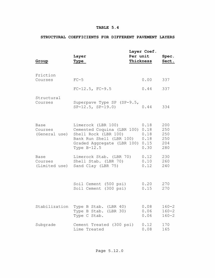
Layer coefficients have been developed which represent the relative strength of different pavement in materials in Florida. The values for these materials are given in Table 5.4. The coefficients presented in this table are based on the best available data. Future adjustments will be made to these values by manual revisions should research or other information dictate. Always design to the nearest 1/2"(10 mm) of structural course.
Page 5.11.0
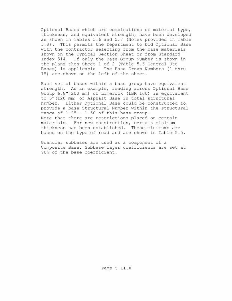
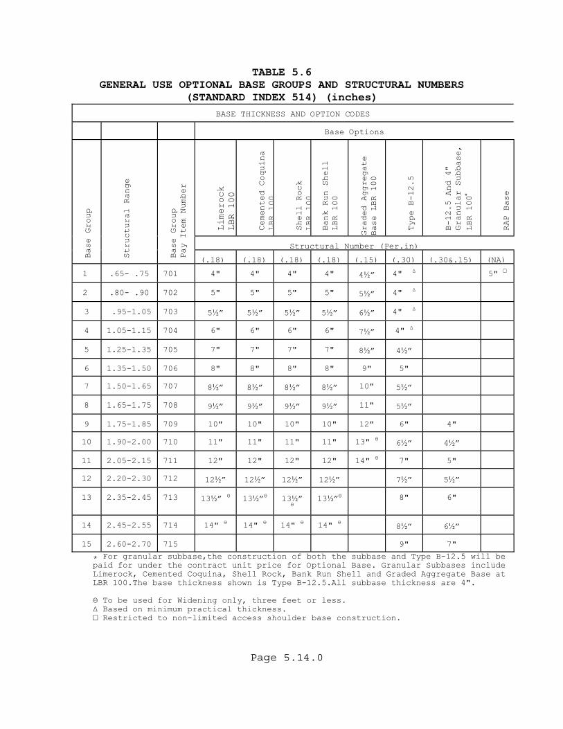
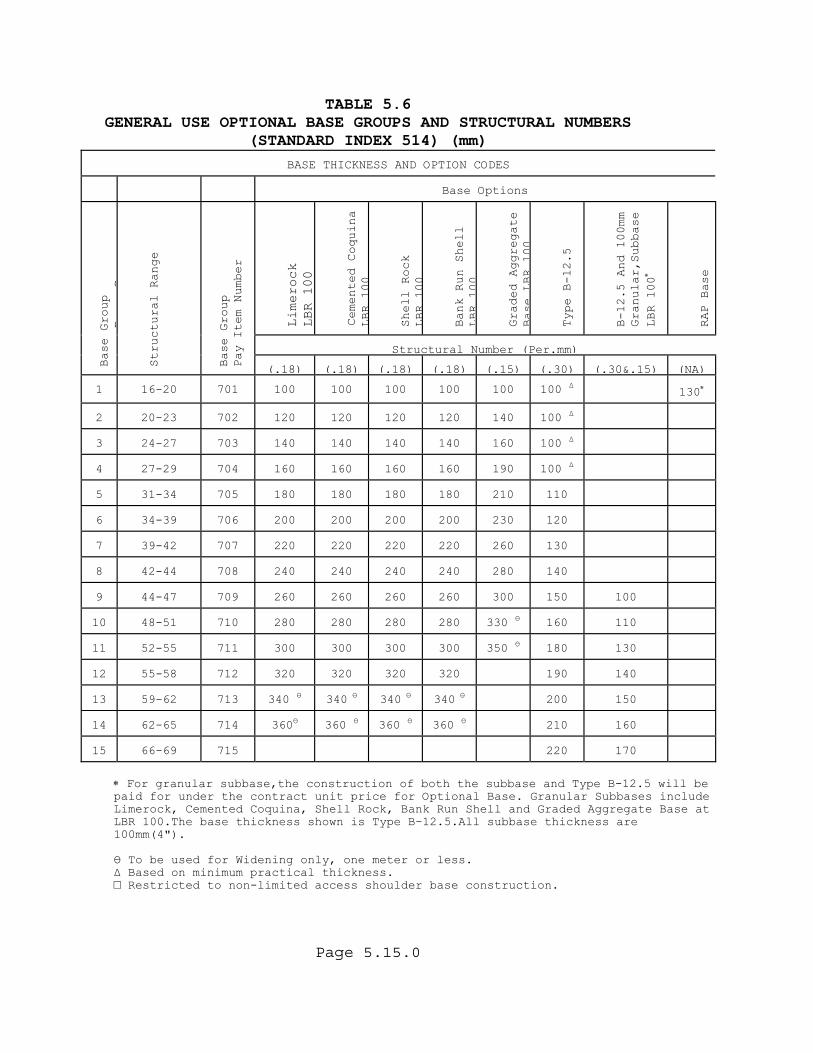
Optional Bases which are combinations of material type, thickness, and equivalent strength, have been developed as shown in Tables 5.6 and 5.7 (Notes provided in Table 5.8). This permits the Department to bid Optional Base with the contractor selecting from the base materials shown on the Typical Section Sheet or from Standard Index 514. If only the Base Group Number is shown in the plans then Sheet 1 of 2 (Table 5.6 General Use Bases) is applicable. The Base Group Numbers (1 thru 15) are shown on the left of the sheet. Each set of bases within a base group have equivalent strength. As an example, reading across Optional Base Group 6,8"(200 mm) of Limerock (LBR 100) is equivalent to 5"(120 mm) of Asphalt Base in total structural number. Either Optional Base could be constructed to provide a base Structural Number within the structural range of 1.35 - 1.50 of this base group. Note that there are restrictions placed on certain materials. For new construction, certain minimum thickness has been established. These minimums are based on the type of road and are shown in Table 5.5. Granular subbases are used as a component of a Composite Base. Subbase layer coefficients are set at 0% of the base coefficient. 9
Page 5.12.0
TABLE 5.4 STRUCTURAL COEFFICIENTS FOR DIFFERENT PAVEMENT LAYERS
Layer Coef.
Layer Per unit Spec. Group Type Thickness Sect.
Friction Courses FC-5 0.00 337
FC-12.5, FC-9.5 0.44 337
Structural Courses Superpave Type SP (SP-9.5,
SP-12.5, SP-19.0) 0.44 334 Base Limerock (LBR 100) 0.18 200 Courses Cemented Coquina (LBR 100) 0.18 250 (General use) Shell Rock (LBR 100) 0.18 250
Bank Run Shell (LBR 100) 0.18 250 Graded Aggregate (LBR 100) 0.15 204 Type B-12.5 0.30 280
Base Limerock Stab. (LBR 70) 0.12 230 Courses Shell Stab. (LBR 70) 0.10 260 (Limited use) Sand Clay (LBR 75) 0.12 240
Soil Cement (500 psi) 0.20 270 Soil Cement (300 psi) 0.15 270
Stabilization Type B Stab. (LBR 40) 0.08 160-2
Type B Stab. (LBR 30) 0.06 160-2 Type C Stab. 0.06 160-2
Subgrade Cement Treated (300 psi) 0.12 170
Lime Treated 0.08 165
Page 5.13.0
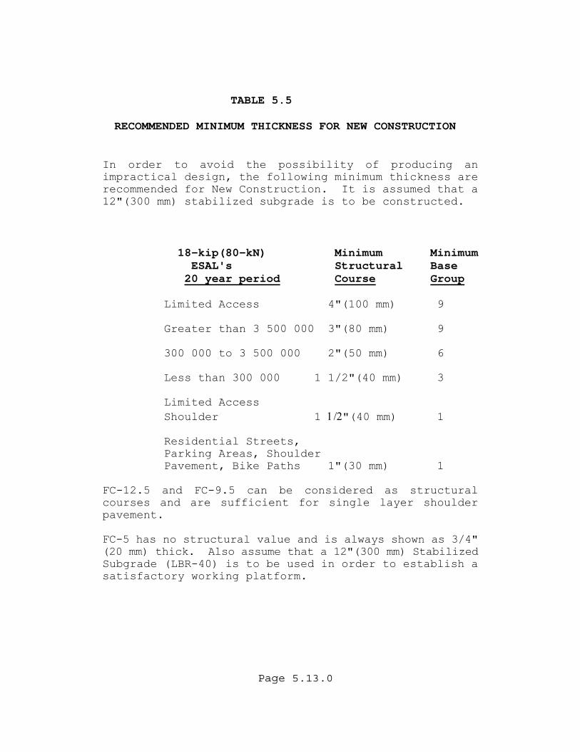
TABLE 5.5 RECOMMENDED MINIMUM THICKNESS FOR NEW CONSTRUCTION
In order to avoid the possibility of producing an impractical design, the following minimum thickness are recommended for New Construction. It is assumed that a 12"(300 mm) stabilized subgrade is to be constructed.
18-kip(80-kN) Minimum Minimum ESAL's Structural Base
20 year period Course Group Limited Access 4"(100 mm) 9 Greater than 3 500 000 3"(80 mm) 9 300 000 to 3 500 000 2"(50 mm) 6
Less than 300 000 1 1/2"(40 mm) 3
Limited Access Shoulder 1 1/2"(40 mm) 1
Residential Streets,
Parking Areas, Shoulder Pavement, Bike Paths 1"(30 mm) 1
FC-12.5 and FC-9.5 can be considered as structural courses and are sufficient for single layer shoulder pavement. FC-5 has no structural value and is always shown as 3/4" (20 mm) thick. Also assume that a 12"(300 mm) Stabilized Subgrade (LBR-40) is to be used in order to establish a satisfactory working platform.
Page 5.14.0
TABLE 5.6 GENERAL USE OPTIONAL BASE GROUPS AND STRUCTURAL NUMBERS
(STANDARD INDEX 514) (inches)
BASE THICKNESS AND OPTION CODES
Base Options
Limerock
LBR 100
Cemented Coquina
LBR
100
Shell Rock
LBR
100
Bank Run Shell
LBR 100
Graded Aggregate
Base LBR 100
Type B-12.5
B-12.5 And 4"
Granular Subbase,
LBR 100
∗
RAP Base
Structural Number (Per.in)
Base Group
Structural Range
Base Group
Pay Item Number
(.18) (.18) (.18) (.18) (.15) (.30)
(.30&.15) (NA)
1
.65- .75
701
4"
4"
4"
4"
4½”
4" ∆
5" □
2
.80- .90
702
5"
5"
5"
5"
5½”
4" ∆
3
.95-1.05
703
5½”
5½”
5½”
5½”
6½”
4" ∆
4
1.05-1.15
704
6"
6"
6"
6"
7½”
4" ∆
5
1.25-1.35
705
7"
7"
7"
7"
8½”
4½”
6
1.35-1.50
706
8"
8"
8"
8"
9"
5"
7
1.50-1.65
707
8½”
8½”
8½”
8½”
10"
5½”
8
1.65-1.75
708
9½”
9½”
9½”
9½”
11"
5½”
9
1.75-1.85
709
10"
10"
10"
10"
12"
6"
4"
10
1.90-2.00
710
11"
11"
11"
11"
13" Ө
6½”
4½”
11
2.05-2.15
711
12"
12"
12"
12"
14" Ө
7"
5"
12
2.20-2.30
712
12½”
12½”
12½”
12½”
7½”
5½”
13
2.35-2.45
713
13½” Ө
13½”Ө
13½”
Ө
13½”Ө
8"
6"
14
2.45-2.55
714
14" Ө
14" Ө
14" Ө
14" Ө
8½”
6½”
15
2.60-2.70
715
9"
7"
For granular subbase,the construction of both the subbase and Type B-12.5 will be ٭paid for under the contract unit price for Optional Base. Granular Subbases include Limerock, Cemented Coquina, Shell Rock, Bank Run Shell and Graded Aggregate Base at LBR 100.The base thickness shown is Type B-12.5.All subbase thickness are 4".
Ө To be used for Widening only, three feet or less. ∆ Based on minimum practical thickness. □ Restricted to non-limited access shoulder base construction.
Page 5.15.0
TABLE 5.6 GENERAL USE OPTIONAL BASE GROUPS AND STRUCTURAL NUMBERS
(STANDARD INDEX 514) (mm)
BASE THICKNESS AND OPTION CODES
Base Options
Limerock
LBR 100
Cemented Coquina
LBR
100
Shell Rock
LBR
100
Bank Run Shell
LBR
100
Graded Aggregate
Base
LBR
100
Type B-12.5
B-12.5 And 100mm
Granular,Subbase
LBR 100
∗
RAP Base
Structural Number (Per.mm)
Base Group
BG
Structural Range
Base Group
Pay Item Number
(.18) (.18) (.18) (.18) (.15) (.30)
(.30&.15) (NA)
1
16-20
701
100
100
100
100
100
100 ∆
130∗
2
20-23
702
120
120
120
120
140
100 ∆
3
24-27
703
140
140
140
140
160
100 ∆
4
27-29
704
160
160
160
160
190
100 ∆
5
31-34
705
180
180
180
180
210
110
6
34-39
706
200
200
200
200
230
120
7
39-42
707
220
220
220
220
260
130
8
42-44
708
240
240
240
240
280
140
9
44-47
709
260
260
260
260
300
150
100
10
48-51
710
280
280
280
280
330 Ө
160
110
11
52-55
711
300
300
300
300
350 Ө
180
130
12
55-58
712
320
320
320
320
190
140
13
59-62
713
340 Ө
340 Ө
340 Ө
340 Ө
200
150
14
62-65
714
360Ө
360 Ө
360 Ө
360 Ө
210
160
15
66-69
715
220
170
∗ For granular subbase,the construction of both the subbase and Type B-12.5 will be paid for under the contract unit price for Optional Base. Granular Subbases include Limerock, Cemented Coquina, Shell Rock, Bank Run Shell and Graded Aggregate Base at LBR 100.The base thickness shown is Type B-12.5.All subbase thickness are 100mm(4"). Ө To be used for Widening only, one meter or less. ∆ Based on minimum practical thickness. □ Restricted to non-limited access shoulder base construction.
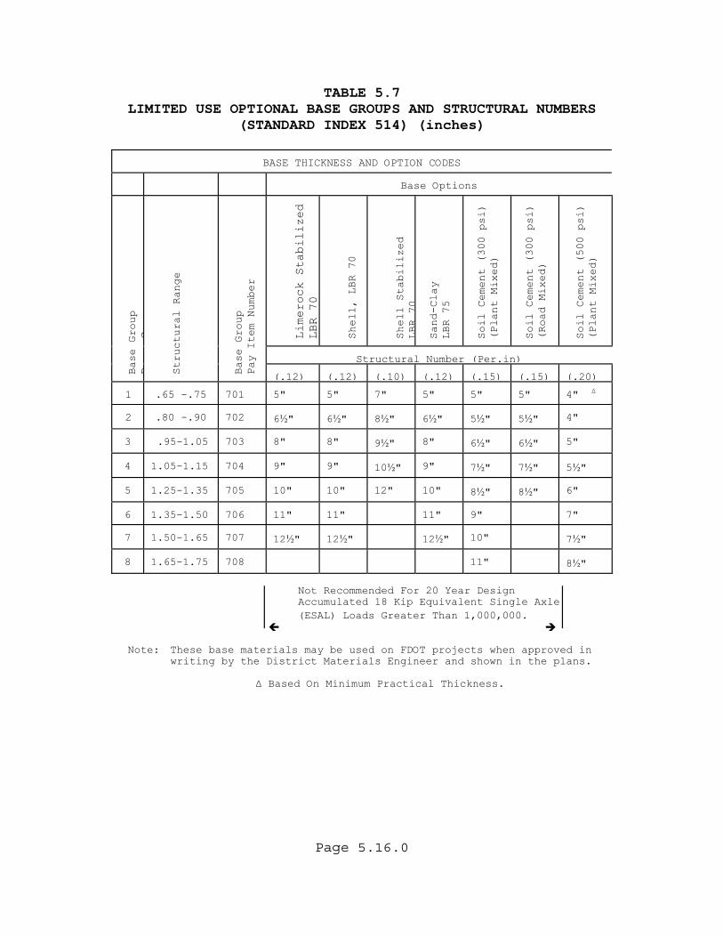
TABLE 5.7 LIMITED USE OPTIONAL BASE GROUPS AND STRUCTURAL NUMBERS (STANDARD INDEX 514) (inches)
BASE THICKNESS AND OPTION CODES
Base Options
Limerock Stabilized
LBR 70
Shell, LBR 70
Shell Stabilized
LBR
70
Sand-Clay
LBR 75
Soil Cement (300 psi)
(Plant Mixed)
Soil Cement (300 psi)
(Road Mixed)
Soil Cement (500 psi)
(Plant Mixed)
Structural Number (Per.in)
Base Group
BG
Structural Range
Base Group
Pay Item Number
(.12) (.12) (.10) (.12) (.15)
(.15)
(.20)
1
.65 -.75
701
5"
5"
7"
5"
5"
5"
4" ∆
2
.80 -.90
702
6½"
6½"
8½"
6½"
5½"
5½"
4"
3
.95-1.05
703
8"
8"
9½"
8"
6½"
6½"
5"
4
1.05-1.15
704
9"
9"
10½"
9"
7½"
7½"
5½"
5
1.25-1.35
705
10"
10"
12"
10"
8½"
8½"
6"
6
1.35-1.50
706
11"
11"
11"
9"
7"
7
1.50-1.65
707
12½"
12½"
12½"
10"
7½"
8
1.65-1.75
708
11"
8½"
Not Recommended For 20 Year Design
Accumulated 18 Kip Equivalent Single Axle (ESAL) Loads Greater Than 1,000,000.
Note: These base materials may be used on FDOT projects when approved in
writing by the District Materials Engineer and shown in the plans.
∆ Based On Minimum Practical Thickness.
Page 5.16.0
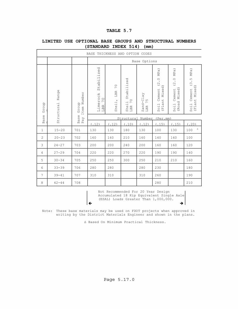
TABLE 5.7 LIMITED USE OPTIONAL BASE GROUPS AND STRUCTURAL NUMBERS (STANDARD INDEX 514) (mm)
BASE THICKNESS AND OPTION CODES
Base Options
Limerock Stabilized
LBR 70
Shell, LBR 70
Shell Stabilized
LBR 70
Sand-Clay
LBR 75
Soil Cement (2.0 MPa)
(Plant Mixed)
Soil Cement (2.0 MPa)
(Road Mixed)
Soil Cement (3.5 MPa)
(Plant Mixed)
Structural Number (Per.mm)
Base Group
BG
Structural Range
Base Group
Pay Item Number
(.12) (.12) (.10) (.12) (.15)
(.15)
(.20)
1
15-20
701
130
130
180
130
100
130
100 ∆
2
20-23
702
160
160
210
160
140
140
100
3
24-27
703
200
200
240
200
160
160
120
4
27-29
704
220
220
270
220
190
190
140
5
30-34
705
250
250
300
250
210
210
160
6
33-39
706
280
280
280
230
180
7
39-41
707
310
310
310
260
190
8
42-44
708
280
210
Page 5.17.0
Not Recommended For 20 Year Design Accumulated 18 Kip Equivalent Single Axle (ESAL) Loads Greater Than 1,000,000.
Note: These base materials may be used on FDOT projects when approved in
writing by the District Materials Engineer and shown in the plans.
∆ Based On Minimum Practical Thickness.

Page 5.18.0
TABLE 5.8
NOTES FOR OPTIONAL BASE GROUPS AND STRUCTURAL NUMBERS (STANDARD INDEX 514)
∗ For granular subbase, the construction of both the subbase and Type B-12.5 will be paid for under the contract unit price for Optional Base. Granular subbases include Limerock, Cemented Coquina, Shell Rock, Bank Run Shell, and Graded Aggregate Base at LBR 100. The base thickness shown is Type B-12.5. All subbase thickness are 4"(100 mm). The base structural number shown is for the composite base.
Ө To be used for widening only, 3'(one meter)
or less.
∆ Base Group 1 based on minimum thickness.
□ Restricted to non-Limited Access shoulder base construction.
General Notes
1. On new construction and complete reconstruction projects where an entirely new base is to be built, the design engineer may specify just the Base Group and any of the unrestricted General Use Optional Bases shown in that base group may be used. Note, however, that some thick granular bases are limited to widening which prevents their general use.
2. Where base options are specified in the plans, only those options may be bid and used.
3. The designer may require the use of a single base option, for instance Type B-12.5 in a high water condition. This will still be bid as Optional Base.
Page 5.19.0
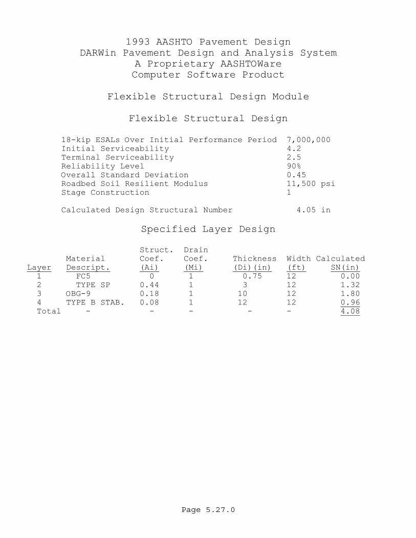
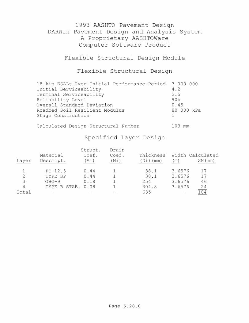
5.4 NEW CONSTRUCTION DESIGN SAMPLE PROBLEM This process is applicable for new construction. The following steps will take place in approximately the order shown with the understanding that some activities can take place concurrently. GIVEN: New Construction four lane, high volume, part urban, part rural, arterial. ESAL = 6,635,835. This value is generally obtained D from the District Planning Office. Round up ESALD to 7,000,000 Traffic Level C (Section 5.5.4) for use in the design tables in Appendix A. MR = 11,500 psi (79 MPa). This value is obtained from the State Materials Office. Round up M to 80 Mpa R for use in the design tables in Appendix A. FIND: The pavement thickness from the information provided for a 20 year design with a design speed of 55 mph(90 km/h) for the rural section and with a design speed of 45 mph(70 km/h) for the urban section (curb and gutter). DATA: %R = 80 to 90. This value is from Table 5.2 for an
Urban Arterial New Construction. %R = 75 to 90 for Rural Arterial New Construction. %R = 90 was chosen by the designer because of the high volume on both sections. SNR can be determined from the design tables in Appendix A for the appropriate reliability. From Table A.4A:
SNR = 4.05" (103 mm) SOLUTION: With the SNR known, the pavement layer thickness can be calculated. Remember that SNC should be within 0.11"(5 mm) of SNR. For the first part of this sample problem using a design speed of 55 mph(90 km/h), we need to use FC-5 according to Table 4.1.
Page 5.20.0
FC-5 has no structural value and is always shown as 3/4". The in-place thickness will average 3/4"(20 mm) with edge rolling down to approximately 1/4"(5 mm). Also assume that a 12"(300 mm) Stabilized Subgrade (LBR-40) is to be used in order to establish a satisfactory working platform. The required base and structural course layer thickness can be determined using the following equation:
SNR = SNCSNR = (a1 x D1) + (a2 x D2) + (a3 x D3) + (a4 x D4)
ENGLISH
4.05" =(0 x 0.75") + (a2 x D2) + (a3 x D3)
+ (0.08 x 12")
4.05" = 0 + (a2 x D2) + (a3 x D3) + 0.96” METRIC
103 mm = (0 x 20 mm) + (a x D2+ (0.08 x 300 mm)
2) + (a3 x D3)
103 mm = 0 + (a2 x D2) + (a3 x D3) + 24 mm
The next step is to calculate the value that the base (a3 x D3) and structural course (a2 x D2) must contribute. To determine this, subtract the stabilized subgrade (a4 x D4 = 0.96) from SNR. ENGLISH
4.05” - 0.96” = (a2 x D2) + (a3 x D3) METRIC
103 mm – 24 mm = (a2 x D2) + (a3 x D3) In this case, the base and structural course must provide the following remaining structural value; ENGLISH
3.09" = (a2 x D2) + (a3 x D3) METRIC
79 mm = (a2 x D2) + (a3 x D3)
Page 5.21.0
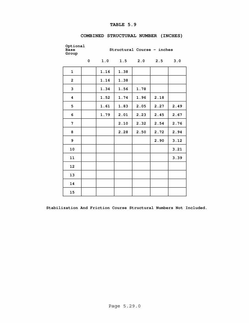
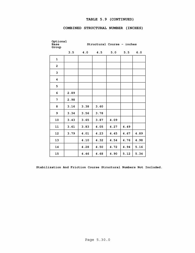
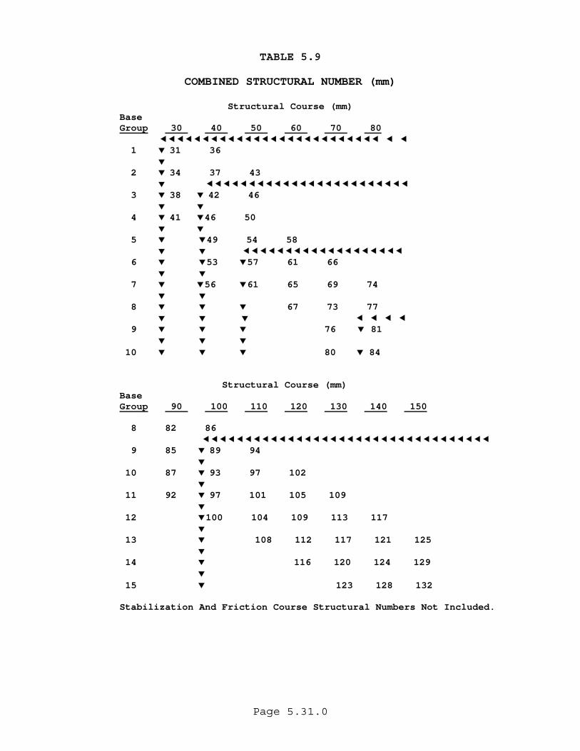
To determine how much each layer (D2 and D3) will contribute, a balanced approach has been provided with the use of Table 5.9. Table 5.9 relates all the optional bases with practical structural course thickness in 2"(10 mm) increments and provides a band of recommended base and structural course thickness. Note that the structural value provided by the stabilization is not included in the Combined Structural Number shown in table 5.9. From Table 5.9, it can be seen that the following combinations would prove satisfactory:
Base Group 8 with 3.50"(90 mm) of structural course with a SN = 3.16"(82 mm)
Base Group 9 with 3.0"(80 mm) of structural course with a SN = 3.12"(81 mm)
Base Group 10 with 3.0"(80 mm) of structural course with a SN = 3.21"(84 mm)
Because this is a Road with ESALD greater than 3 500 000, the minimum thickness must be checked. From Table 5.5, the minimum allowed for this type of road is Optional Base Group 9 with 3"(80 mm) of structural course. One of the combinations selected meets these minimum requirements. If all the combinations were thinner than the minimum, another combination meeting the minimum requirements would be selected. A theoretical over-design using the minimums is not uncommon when a stabilized subgrade is constructed. The construction of at least these minimum thickness is required to provide practical designs that stay within the empirical limits of the AASHO Road Test. If a stabilized subgrade is not constructed due to unusual conditions, the base and structural course would have to provide a structural number of 4.05"(103 mm)
Page 5.22.0
SNR = (a1 x D1) + (a2 x D2) + (a3 x D3) ENGLISH
4.05 = (0 x 0.75") + (a2 x D2) + (a3 x D3) 4.05 = (a2 x D2) + (a3 x D3)
METRIC
103 mm = (0 x 20 mm) + (a x D2103 mm = (a
2) + (a3 x D3) 2 x D2) + (a3 x D3)
From Table 5.9 an Optional Base Group 10 and 5.0"(120 mm) of structural course would give a structural number of 4.09"(102 mm). This would be satisfactory as the base and structural course exceed the required minimums. For the second part of this sample problem using a design speed of 45 mph (70 km/h), we need to use FC-12.5 or FC-9.5 according to Table 4.1. FC-12.5 or FC-9.5 has the same structural value as Type SP and are considered as structural layers. FC-12.5 is always shown as 1 1/2"(40 mm) thick and FC-9.5 is always shown as 1 "(30 mm) thick. For this problem, use Optional Base Group 9 with 1 1/2 (40 mm) of Type SP Structural Course and 1 1/2"(40 mm) FC-12.5 or Use Optional Base Group 9 with 2"(50 mm) of Type SP Structural Course and 1"(30 mm) FC-9.5.
Page 5.23.0
CONCLUSION:
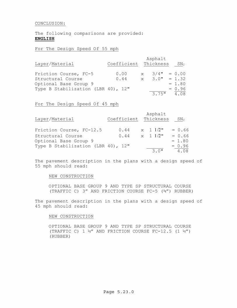
The following comparisons are provided: ENGLISH For The Design Speed Of 55 mph Asphalt Layer/Material Coefficient Thickness SN C Friction Course, FC-5 0.00 x 3/4" = 0.00 Structural Course 0.44 x 3.0" = 1.32 Optional Base Group 9 = 1.80 Type B Stabilization (LBR 40), 12" = 0.96 3.75" 4.08 For The Design Speed Of 45 mph Asphalt Layer/Material Coefficient Thickness SN C Friction Course, FC-12.5 0.44 x 1 1/2" = 0.66 Structural Course 0.44 x 1 1/2" = 0.66 Optional Base Group 9 = 1.80 Type B Stabilization (LBR 40), 12" = 0.96 3.0" 4.08 The pavement description in the plans with a design speed of 55 mph should read:
NEW CONSTRUCTION
OPTIONAL BASE GROUP 9 AND TYPE SP STRUCTURAL COURSE (TRAFFIC C) 3” AND FRICTION COURSE FC-5 (¾”) RUBBER)
The pavement description in the plans with a design speed of 45 mph should read:
NEW CONSTRUCTION
OPTIONAL BASE GROUP 9 AND TYPE SP STRUCTURAL COURSE (TRAFFIC C) 1 ½” AND FRICTION COURSE FC-12.5 (1 ½”) (RUBBER)
Page 5.24.0
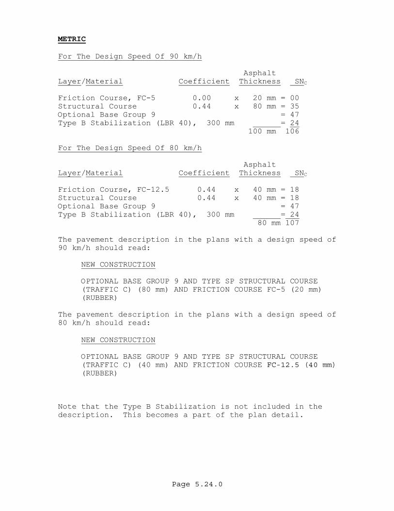
METRIC For The Design Speed Of 90 km/h Asphalt Layer/Material Coefficient Thickness SN C Friction Course, FC-5 0.00 x 20 mm = 00 Structural Course 0.44 x 80 mm = 35 Optional Base Group 9 = 47 Type B Stabilization (LBR 40), 300 mm = 24 100 mm 106 For The Design Speed Of 80 km/h Asphalt Layer/Material Coefficient Thickness SN C Friction Course, FC-12.5 0.44 x 40 mm = 18 Structural Course 0.44 x 40 mm = 18 Optional Base Group 9 = 47 Type B Stabilization (LBR 40), 300 mm = 24 80 mm 107 The pavement description in the plans with a design speed of 90 km/h should read:
NEW CONSTRUCTION
OPTIONAL BASE GROUP 9 AND TYPE SP STRUCTURAL COURSE (TRAFFIC C) (80 mm) AND FRICTION COURSE FC-5 (20 mm) (RUBBER)
The pavement description in the plans with a design speed of 80 km/h should read:
NEW CONSTRUCTION
OPTIONAL BASE GROUP 9 AND TYPE SP STRUCTURAL COURSE (TRAFFIC C) (40 mm) AND FRICTION COURSE FC-12.5 (40 mm) (RUBBER)
Note that the Type B Stabilization is not included in the description. This becomes a part of the plan detail.
Page 5.25.0
Design, Analysis, and Rehabilitation for Windows (DARWin) Examples. In addition to using Design Tables, AASHTO DARWin pavement design software can be used for performing pavement design as shown in the examples in pages 5.26.0 to 5.28.0 For F.D.O.T use, the software can be obtained from the Pavement Management Office, by request through the Districts Pavement Design Engineers. For Consultants, and Local government agencies, the software should be purchased from AASHTO.
Page 5.26.0
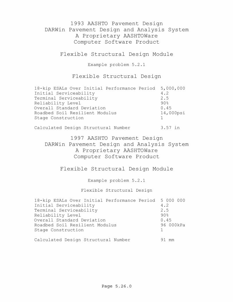
1993 AASHTO Pavement Design DARWin Pavement Design and Analysis System
A Proprietary AASHTOWare Computer Software Product
Flexible Structural Design Module
Example problem 5.2.1
Flexible Structural Design
18-kip ESALs Over Initial Performance Period 5,000,000 Initial Serviceability 4.2 Terminal Serviceability 2.5 Reliability Level 90% Overall Standard Deviation 0.45 Roadbed Soil Resilient Modulus 14,000psi Stage Construction 1 Calculated Design Structural Number 3.57 in
1997 AASHTO Pavement Design DARWin Pavement Design and Analysis System
A Proprietary AASHTOWare Computer Software Product
Flexible Structural Design Module
Example problem 5.2.1
Flexible Structural Design
18-kip ESALs Over Initial Performance Period 5 000 000 Initial Serviceability 4.2 Terminal Serviceability 2.5 Reliability Level 90% Overall Standard Deviation 0.45 Roadbed Soil Resilient Modulus 96 000kPa Stage Construction 1 Calculated Design Structural Number 91 mm
Page 5.27.0
1993 AASHTO Pavement Design DARWin Pavement Design and Analysis System
A Proprietary AASHTOWare Computer Software Product
Flexible Structural Design Module
Flexible Structural Design
18-kip ESALs Over Initial Performance Period 7,000,000 Initial Serviceability 4.2 Terminal Serviceability 2.5 Reliability Level 90% Overall Standard Deviation 0.45
Roadbed Soil Resilient Modulus 11,500 psi Stage Construction 1
Calculated Design Structural Number 4.05 in
Specified Layer Design
Struct. Drain
Material Coef. Coef. Thickness Width Calculated Layer Descript. (Ai) (Mi) (Di)(in) (ft) SN(in) 1 FC5 0 1 0.75 12 0.00 2 TYPE SP 0.44 1 3 12 1.32 3 OBG-9 0.18 1 10 12 1.80 4 TYPE B STAB. 0.08 1 12 12 0.96 Total - - - - - 4.08
Page 5.28.0
1993 AASHTO Pavement Design DARWin Pavement Design and Analysis System
A Proprietary AASHTOWare Computer Software Product
Flexible Structural Design Module
Flexible Structural Design
18-kip ESALs Over Initial Performance Period 7 000 000 Initial Serviceability 4.2 Terminal Serviceability 2.5 Reliability Level 90% Overall Standard Deviation 0.45 Roadbed Soil Resilient Modulus 80 000 kPa Stage Construction 1 Calculated Design Structural Number 103 mm
Specified Layer Design
Struct. Drain Material Coef. Coef. Thickness Width Calculated
Layer Descript. (Ai) (Mi) (Di)(mm) (m) SN(mm) 1 FC-12.5 0.44 1 38.1 3.6576 17 2 TYPE SP 0.44 1 38.1 3.6576 17 3 OBG-9 0.18 1 254 3.6576 46 4 TYPE B STAB. 0.08 1 304.8 3.6576 24 Total - - - 635 - 104
Page 5.29.0
TABLE 5.9
COMBINED STRUCTURAL NUMBER (INCHES)
Optional Base Group
Structural Course - inches
0 1.0 1.5 2.0 2.5 3.0
1
1.16
1.38
2
1.16
1.38
3
1.34
1.56
1.78
4
1.52
1.74
1.96
2.18
5
1.61
1.83
2.05
2.27
2.49
6
1.79
2.01
2.23
2.45
2.67
7
2.10
2.32
2.54
2.76
8
2.28
2.50
2.72
2.94
9
2.90
3.12
10
3.21
11
3.39
12
13
14
15
Stabilization And Friction Course Structural Numbers Not Included.
Page 5.30.0
TABLE 5.9 (CONTINUED)
COMBINED STRUCTURAL NUMBER (INCHES)
Optional Base Group
Structural Course - inches
3.5 4.0 4.5 5.0 5.5 6.0 1
2
3
4
5
6
2.89
7
2.98
8
3.16
3.38
3.60
9
3.34
3.56
3.78
10
3.43
3.65
3.87
4.09
11
3.61
3.83
4.05
4.27
4.49
12
3.79
4.01
4.23
4.45
4.67
4.89
13
4.10
4.32
4.54
4.76
4.98
14
4.28
4.50
4.72
4.94
5.16
15
4.46
4.68
4.90
5.12
5.34
Stabilization And Friction Course Structural Numbers Not Included.
Page 5.31.0
TABLE 5.9
COMBINED STRUCTURAL NUMBER (mm)
Structural Course (mm) Base Group 30 40 50 60 70 80
1 31 36
2 34 37 43
3 38
42 46
4
41 46 50
5 49 54 58
6 53
57 61 66
7 56 61 65 69 74 8 67 73 77
9 76 81
10 80 84
Structural Course (mm) Base Group 90 100 110 120 130 140 150
8 82 86
9 85 89 94
10 87 93 97 102
11 92 97 101 105 109
12 100 104 109 113 117 13 108 112 117 121 125
14 116 120 124 129 15 123 128 132
Stabilization And Friction Course Structural Numbers Not Included.
Page 5.32.0
5.5 DESIGN CONSIDERATIONS The following special areas need to be addressed by the Pavement Design Engineer as the project develops. 5.5.1 STABILIZATION Since stabilized subgrade has a history of good performance and provides strength to the pavement system at a low cost, it is highly recommended that a stabilized subgrade element be included in a pavement design as shown in the Plans Preparation Manual. In some situations, project conditions may dictate elimination of a stabilized subgrade during design and achieving the Required Structural Number (SNR) with base course and asphalt structural course. These conditions might include:
• Limited working areas at intersections or in medians. • Shallow existing utilities that are impractical to
relocate. • Areas of urban projects where it is essential to
accelerate construction to limit restriction of access to adjacent businesses.
Stabilized subgrade should not normally be eliminated over extensive areas, because it is necessary to provide a working platform for base construction operations. This is an especially important consideration with asphalt base course, because of the difficulty in achieving compaction of the first course placed on an unstable subgrade. On rural highways, stabilized subgrade should extend to the shoulder point in order to provide a stable shoulder condition. On urban projects, stabilized subgrade is usually necessary to support curb and gutter. The District Construction Engineer should be consulted prior to deciding to eliminate stabilized subgrade in design. The reasons for eliminating stabilized subgrade must be documented in the project file. In situations where construction time is critical, the following alternates to insitu sampling and testing to determine the Limerock Bearing Ratio (LBR) value of a
Page 5.33.0
stabilized subgrade include:
• Mixing of soil and stabilized material and testing off site.
• Use of a natural occurring material that meets the Limerock Bearing Ratio (LBR) value requirement that has been tested at the source.
• Use of a Predesigned Stabilized Subgrade per the Special Provisions covering this concept. The
Specifications also provides that when 12"(300 mm) of Type B Stabilization requiring an LBR value of 40 is called for, the Engineer may allow, at no additional compensation, the substitution of 6"(150 mm) of Granular Subbase meeting the requirements of section 290. These alternatives should be discussed with the District Construction Engineer and the District Materials Engineer and appropriate Special Provisions included in the Project Specifications. The specifications provide for use of the No Soak LBR Test Method to expedite LBR testing under certain conditions. Use of this test method is at the option of the Contractor if approved by the District Materials Engineer. 5.5.2 BASE Except as limited by Standard Index 514 or as may be justified by special project conditions, the options for base material should not be restricted. Allowing the contractor the full range of base materials will permit him to select the least costly material, thus resulting in the lowest bid price. Unbound granular base materials are generally the least expensive. Project conditions may dictate restricting the base course to Asphalt Base Course. The following conditions may warrant restricting the base course to Asphalt Base Course (Type B-12.5) if the additional cost can be justified:
Page 5.34.0
• In an urban area, maintenance of access to adjacent business is critical to the extent that it is desirable to accelerate base construction.
• The maintenance of traffic scheme requires acceleration
of base construction in certain areas of the project.
• High ground water and back of sidewalk grade restrictions make it difficult to obtain adequate design high water clearance from the bottom of a thicker limerock base. The thinner asphalt base can help increase the clearance. NOTE that asphalt base requires a well compacted subgrade, just as limerock base. It is usually necessary to have two feet(0.6 m) clearance above ground water to get adequate compaction in the top foot(0.3 m) of subgrade. In areas where this cannot be obtained, the District Drainage Engineer should be consulted for an underdrain design or other methods to lower the ground water.
• The configuration of base widening and subgrade soil
conditions are such that accumulation of rainfall in excavated areas will significantly delay construction.
The Pavement Design Engineer should become familiar with the material properties, construction techniques, testing procedures, and maintenance of traffic techniques that may enter into the decision to restrict the type of base material to be used. Consultation with the District Construction Engineer and the District Materials Engineer should be done prior to making any decision. A decision to restrict base course material to an Asphalt Base Course throughout a project must be documented and approved by the District Design Engineer. A copy of the documentation shall be furnished to the State Pavement Design Engineer. Base courses are normally set up under Optional Base Group (OBG) bid item.
Page 5.35.0
On projects where the Pavement Design Engineer would like to use Asphalt Base (Type B-12.5) on a part of a project and allow multiple base options on other parts of the projects, the Pavement Design Engineer should change the Optional Base Group (OBG) Number by one and specify Asphalt Base only for the area where it is required. An example of a project where this may occur would be on a project where OBG 6 is recommended and the Pavement Design Engineer encounters an area of high water. The option would be to use Type B-12.5 from OBG 7. Another option would be to use Type B-12.5 from OBG 5. In both cases the structural asphalt thickness can be adjusted to meet the structural number requirements and allow for separate unit prices. The Optional Base Group should not exceed Optional Base Group 12 for unbound granular base materials, except for trench widening where up to Optional Base Group 14 may be used. 5.5.3 ASPHALT BASE CURB PAD When asphalt base only is decided on for a curb and gutter project, it is generally advisable to show, on the typical section, an asphalt Type B-12.5 pad under the curb (see PPM exhibit TYP-6A for example). The thickness of the asphalt pad should be determined by constructibility sketch and shown in the plans, so that the bottom of the curb pad matches the bottom of the initial lift of asphalt base. This will allow the initial lift of the asphalt base to include the curb pad and to be placed prior to the curb placement. This will protect the subgrade from rain earlier and potentially speed up construction. Since the thickness of the asphalt curb pad will be less than the asphalt base, a standard plan note should be added, stating that the cost of curb pad is to be included in the cost of curb and gutter. The Base Group may need to be increased to provide for a minimum of 1 ½”(40 mm) of asphalt curb pad.
Page 5.36.0
5.5.4 STRUCTURAL COURSE Individual asphalt layers are not shown on the Plans Typical Section, only the overall asphalt thickness as prescribed in the Plans Preparation Manual. Variations can occur when recommended in advance by the District Bituminous Engineer and concurred with by the District Pavement Design Engineer. For unusual situations, the State Pavement Management Office and the State Materials Office should be consulted. The Pavement Design Engineer shall sketch out the construction sequence of the Typical Section to ensure contructibility. This sketch is to be included in the pavement design package. Emphasis should be placed on allowing the final structural layer to be placed on the mainline and shoulder at the same time. This makes construction easier for the contractor and improves the final product by avoiding a construction joint at the shoulder. Type SP mixes are designated in the plans by Traffic Level, based on the design ESALD and Table 5.10. The same Traffic Level as the roadway should be used for shoulders 5'(1.5 m) or less, where the final layer is paved in one pass with the roadway. For shoulders wider than 5'(1.5m) refer to chapter 8 of this manual. As a practical matter, Superpave mixes for crossroads and other small sections with quantities less than 1000 tons can be designed with the same mix (i.e. Traffic Level) as the mainline. This should be discussed on a project by project basis with the District Bituminous Engineer.
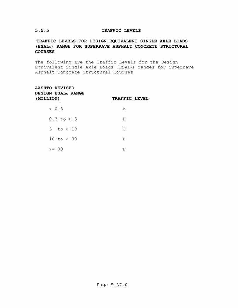
Page 5.37.0
5.5.5 TRAFFIC LEVELS TRAFFIC LEVELS FOR DESIGN EQUIVALENT SINGLE AXLE LOADS (ESALD) RANGE FOR SUPERPAVE ASPHALT CONCRETE STRUCTURAL COURSES The following are the Traffic Levels for the Design Equivalent Single Axle Loads (ESALD) ranges for Superpave sphalt Concrete Structural Courses A
AASHTO REVISED DESIGN ESAL RANGE D
(MILLION) TRAFFIC LEVEL
< 0.3 A
0.3 to < 3 B 3 to < 10 C
10 to < 30 D
>= 30 E
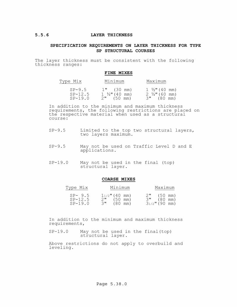
Page 5.38.0
5.5.6 LAYER THICKNESS
SPECIFICATION REQUIREMENTS ON LAYER THICKNESS FOR TYPE
SP STRUCTURAL COURSES The layer thickness must be consistent with the following thickness ranges:
FINE MIXES
ype MixT Minimum Maximum
SP-9.5 1" (30 mm) 1 ½"(40 mm) SP-12.5 1 "(40 mm) 2 "(60 mm)
SP-19.0 2" (50 mm) 3" (80 mm) ½ ½
In addition to the minimum and maximum thickness
requirements, the following restrictions are placed on the respective material when used as a structural course:
SP-9.5 Limited to the top two structural layers, two layers maximum.
SP-9.5 May not be used on Traffic Level D and E
applications.
SP-19.0 May not be used in the final (top) structural layer.
COARSE MIXES
Type Mix Minimum Maximum
SP- 9.5 11/2"(40 mm) 2" (50 mm) SP-12.5 2" (50 mm) 3" (80 mm)
SP-1
9.0 3" (80 mm) 31/2"(90 mm)
In addition to the minimum and maximum thickness
requirements,
SP-19.0 May not be used in the final(top) structural layer.
Above restrictions do not apply to overbuild and leveling.
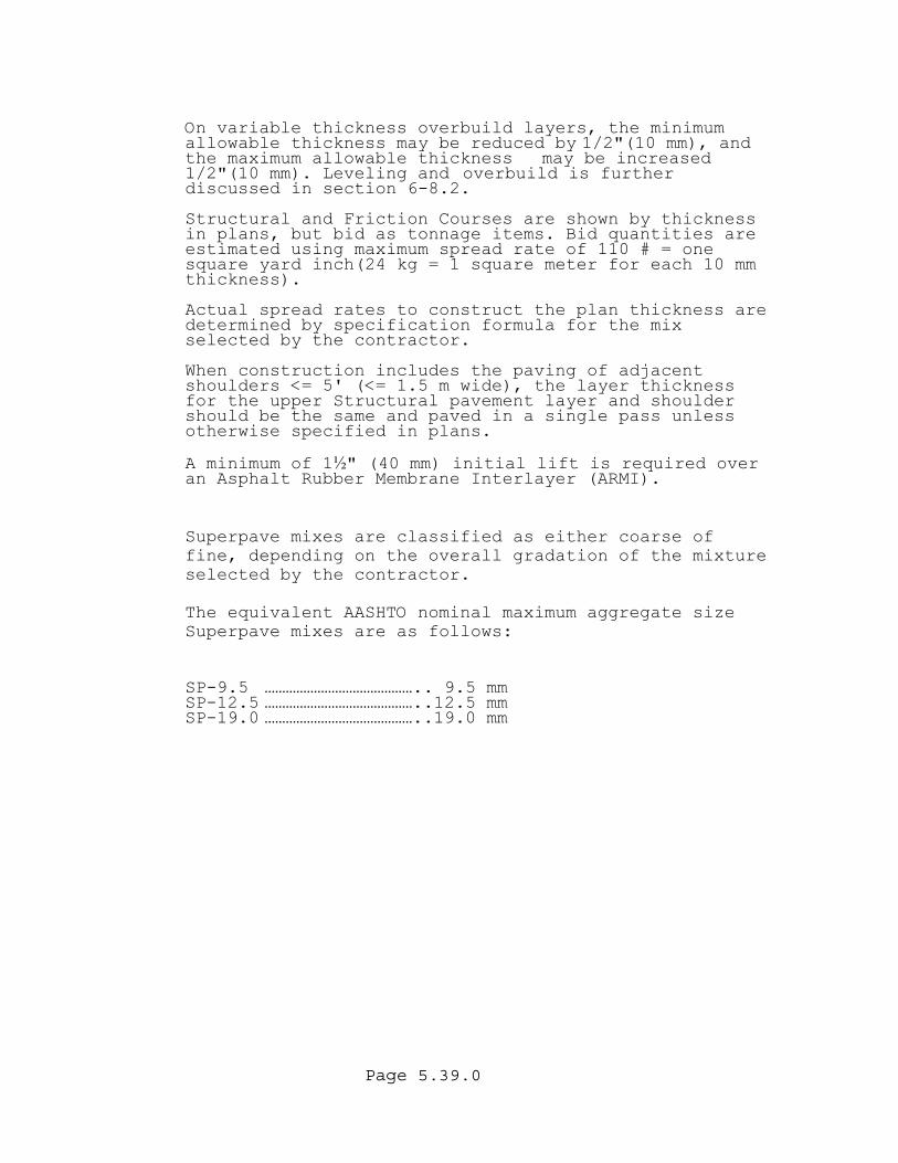
Page 5.39.0
On variable thickness overbuild layers, the minimum allowable thickness may be reduced by 1/2"(10 mm), and the maximum allowable thickness may be increased 1/2"(10 mm). Leveling and overbuild is further discussed in section 6-8.2.
Structural and Friction Courses are shown by thickness in plans, but bid as tonnage items. Bid quantities are estimated using maximum spread rate of 110 # = one square yard inch(24 kg = 1 square meter for each 10 mm thickness).
Actual spread rates to construct the plan thickness are determined by specification formula for the mix elected by the contractor. s
When construction includes the paving of adjacent shoulders <= 5' (<= 1.5 m wide), the layer thickness for the upper Structural pavement layer and shoulder should be the same and paved in a single pass unless otherwise specified in plans.
A minimum of 1½" (40 mm) initial lift is required over an Asphalt Rubber Membrane Interlayer (ARMI).
Superpave mixes are classified as either coarse of fine, depending on the overall gradation of the mixture selected by the contractor. The equivalent AASHTO nominal maximum aggregate size Superpave mixes are as follows:
SP-9.5 …………………………………….. 9.5 mm SP-12.5 ……………………………………..12.5 mm
.0 ……………………………………..19.0 mm SP-19
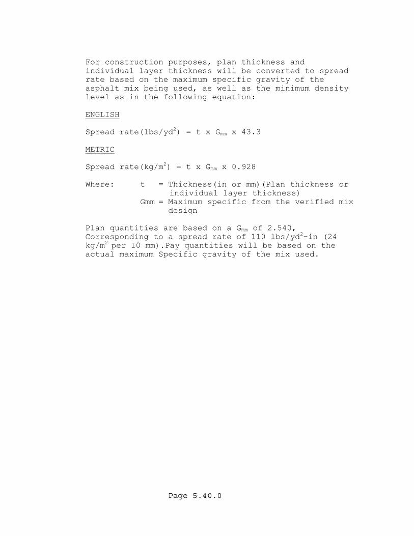
Page 5.40.0
For construction purposes, plan thickness and individual layer thickness will be converted to spread rate based on the maximum specific gravity of the asphalt mix being used, as well as the minimum density level as in the following equation: ENGLISH Spread rate(lbs/yd2) = t x Gmm x 43.3 METRIC Spread rate(kg/m2) = t x Gmm x 0.928 Where: t = Thickness(in or mm)(Plan thickness or
individual layer thickness) Gmm = Maximum specific from the verified mix
design Plan quantities are based on a G of 2.540, mmCorresponding to a spread rate of 110 lbs/yd2-in (24 kg/m2 per 10 mm).Pay quantities will be based on the actual maximum Specific gravity of the mix used.
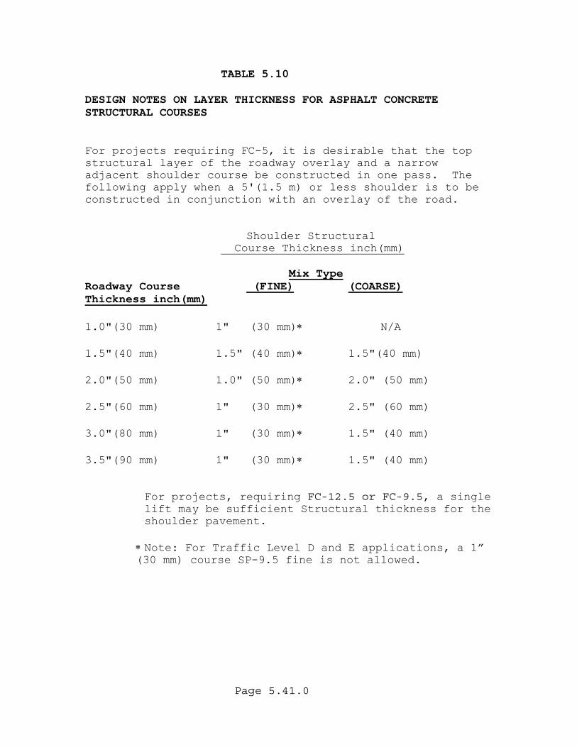
Page 5.41.0
TABLE 5.10 DESIGN NOTES ON LAYER THICKNESS FOR ASPHALT CONCRETE STRUCTURAL COURSES For projects requiring FC-5, it is desirable that the top structural layer of the roadway overlay and a narrow adjacent shoulder course be constructed in one pass. The following apply when a 5'(1.5 m) or less shoulder is to be constructed in conjunction with an overlay of the road. Shoulder Structural Course Thickness inch(mm)
Mix Type Roadway Course (FINE) (COARSE) Thickness inch(mm) 1.0"(30 mm) 1" (30 mm)∗ N/A 1.5"(40 mm) 1.5" (40 mm)∗ 1.5"(40 mm) 2.0"(50 mm) 1.0" (50 mm)∗ 2.0" (50 mm) 2.5"(60 mm) 1" (30 mm)∗ 2.5" (60 mm) 3.0"(80 mm) 1" (30 mm)∗ 1.5" (40 mm)
3.5"(90 mm) 1" (30 mm)∗ 1.5" (40 mm)
For projects, requiring FC-12.5 or FC-9.5, a single lift may be sufficient Structural thickness for the shoulder pavement.
∗ Note: For Traffic Level D and E applications, a 1” (30 mm) course SP-9.5 fine is not allowed.

Page 5.42.0
TABLE 5.11 COARSE MIXES
LAYER THICKNESS FOR ASPHALTIC CONCRETE STRUCTURAL COURSES (Layers are Listed in Sequence Of Construction)
LAYER THICKNESS (inches)
COURSE THICKNESS (inches)
SP-19.0 with SP-12.5 Top
Layer
SP-19.0 with SP-9.5 Top Layer
SP-12.5
SP-12.5 with SP-9.5 Top Layer
SP-9.5
SP-19.0 1st Layer with SP-9.5 2nd Layer and Top Layer
SP-12.5 1st Layer with SP-9.5 2nd Layer and Top Layer
1
2
1
2
1
2
3
1
2
3
1
2
3
1
2
3
1
2
3
1
1 1/2
11/2
2
2
2
2 1/2
21/2
3
3
11/2
11/2
3 1/2
2
11/2
2
2
2
2
2
2
4
21/2
11/2
21/2
11/2
3
11/2
21/2
2
3
11/2
4 1/2
2
21/2
11/2
11/2
11/2
3
2
3
2
3
2
3
2
2
11/2
11/2
2
11/2
11/2
5
31/2
11/2
2
3
11/2
11/2
2
31/2
2
31/2
2
3
21/2
2
2
11/2
2
2
11/2
2
2
11/2
5 1/2
21/2
3
2
11/2
2
2
11/2
2
31/2
21/2
3
3
2
2
2
2
2
2
3
11/2
11/2
2
2
2
6
3 3
2
2
2
21/2
2
11/2
3
11/2
11/2
Minimum And Maximum Layer Thickness For Coarse Mixes
Type Mix Min. Max. SP-9.5 11/2" (40 mm) 2" (50 mm) SP-12.5 2" (50 mm) 3" (80 mm) SP-19.0 3" (80 mm) 3 1/2" (90 mm)
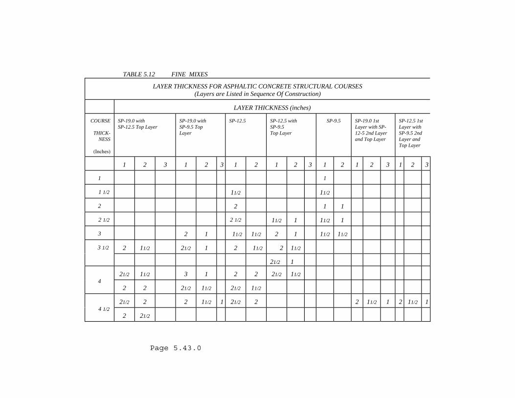
TABLE 5.12 FINE MIXES
LAYER THICKNESS FOR ASPHALTIC CONCRETE STRUCTURAL COURSES (Layers are Listed in Sequence Of Construction)
LAYER THICKNESS (inches)
COURSE
THICK- NESS
(Inches)
SP-19.0 with SP-12.5 Top Layer
SP-19.0 with SP-9.5 Top Layer
SP-12.5
SP-12.5 with SP-9.5 Top Layer
SP-9.5
SP-19.0 1st Layer with SP-12-5 2nd Layer and Top Layer
SP-12.5 1st Layer with SP-9.5 2nd Layer and Top Layer
1
2
3
1
2
3
1
2
1
2
3
1
2
1
2
3
1
2
3
1
1
1 1/2
11/2
11/2
2
2
1
1
2 1/2
2 1/2
11/2
1
11/2
1
3
2
1
11/2
11/2
2
1
11/2
11/2
2
11/2
21/2
1
2
11/2
2
11/2
3 1/2
21/2
1
21/2
11/2
3
1
2
2
21/2
11/2
4 2
2
21/2
11/2
21/2
11/2
21/2
2
2
11/2
1
21/2
2
2
11/2
1
2
11/2
1
4 1/2 2
21/2
Page 5.43.0
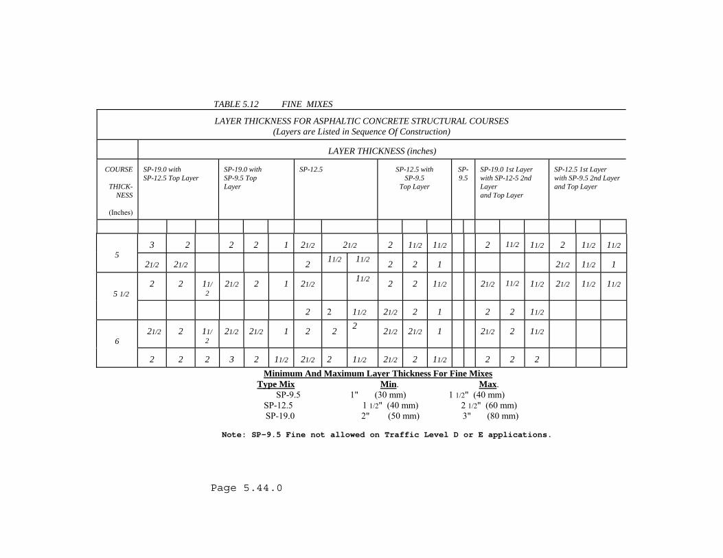
TABLE 5.12 FINE MIXES
LAYER THICKNESS FOR ASPHALTIC CONCRETE STRUCTURAL COURSES (Layers are Listed in Sequence Of Construction)
LAYER THICKNESS (inches)
COURSE
THICK- NESS
(Inches)
SP-19.0 with SP-12.5 Top Layer
SP-19.0 with SP-9.5 Top Layer
SP-12.5
SP-12.5 with
SP-9.5 Top Layer
SP-9.5
SP-19.0 1st Layer with SP-12-5 2nd Layer and Top Layer
SP-12.5 1st Layer with SP-9.5 2nd Layer and Top Layer
3
2
2
2
1 21/2
21/2
2
11/2
11/2
2
11/2
11/2
2
11/2
11/2
5 21/2
21/2
2 11/2 11/2
2
2
1
21/2
11/2
1
2
2
11/2
21/2
2
1
21/2
11/2
2
2 11/2
21/2
11/2
11/2
21/2
11/2
11/2
5 1/2
2 2
11/2
21/2
2
1
2
2
11/2
21/2
2
11/2
21/2
21/2
1
2
2 2
21/2 21/2
1
21/2
2
11/2
6
2
2
2
3
2 11/2
21/2
2
11/2
21/2
2
11/2
2
2
2
Minimum And Maximum Layer Thickness For Fine Mixes Type Mix Min. Max.
SP-9.5 1" (30 mm) 1 1/2" (40 mm) SP-12.5 1 1/2" (40 mm) 2 1/2" (60 mm)
SP-19.0 2" (50 mm) 3" (80 mm)
Note: SP-9.5 Fine not allowed on Traffic Level D or E applications.
Page 5.44.0
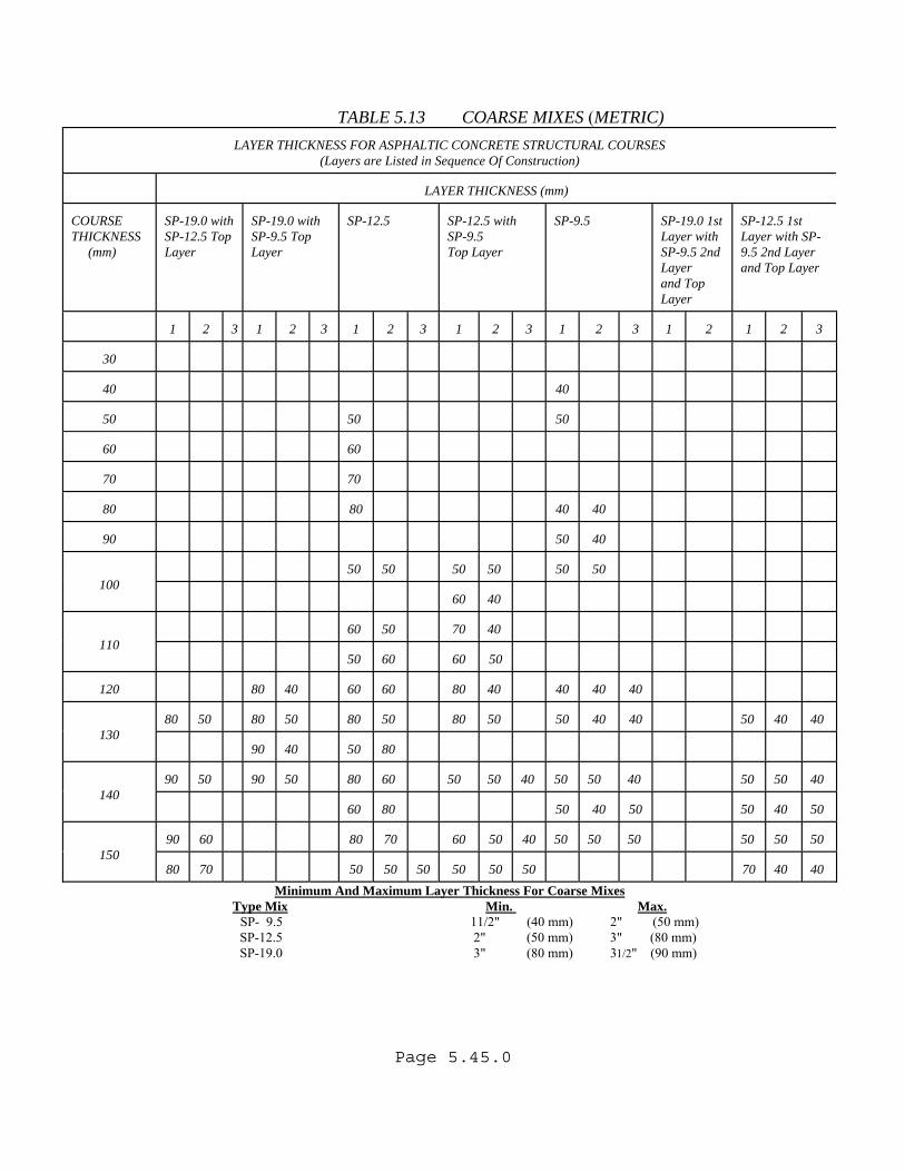
Page 5.45.0
TABLE 5.13 COARSE MIXES (METRIC)
LAYER THICKNESS FOR ASPHALTIC CONCRETE STRUCTURAL COURSES (Layers are Listed in Sequence Of Construction)
LAYER THICKNESS (mm)
COURSE THICKNESS (mm)
SP-19.0 with SP-12.5 Top Layer
SP-19.0 with SP-9.5 Top Layer
SP-12.5
SP-12.5 with SP-9.5 Top Layer
SP-9.5
SP-19.0 1st Layer with SP-9.5 2nd Layer and Top Layer
SP-12.5 1st Layer with SP-9.5 2nd Layer and Top Layer
1
2
3
1
2
3
1
2
3
1
2
3
1
2
3
1
2
1
2
3
30
40
40
50
50
50
60
60
70
70
80
80
40
40
90
50
40
50
50
50
50
50
50
100
60
40
60
50
70
40
110
50
60
60
50
120
80
40
60
60
80
40
40
40
40
80
50
80
50
80
50
80
50
50
40
40
50
40
40
130
90
40
50
80
90
50
90
50
80
60
50
50
40
50
50
40
50
50
40
140
60
80
50
40
50
50
40
50
90
60
80
70
60
50
40
50
50
50
50
50
50
150 80
70
50
50
50
50
50
50
70
40
40
Minimum And Maximum Layer Thickness For Coarse Mixes Type Mix Min. Max.
SP- 9.5 11/2" (40 mm) 2" (50 mm) SP-12.5 2" (50 mm) 3" (80 mm)
SP-19.0 3" (80 mm) 31/2" (90 mm)
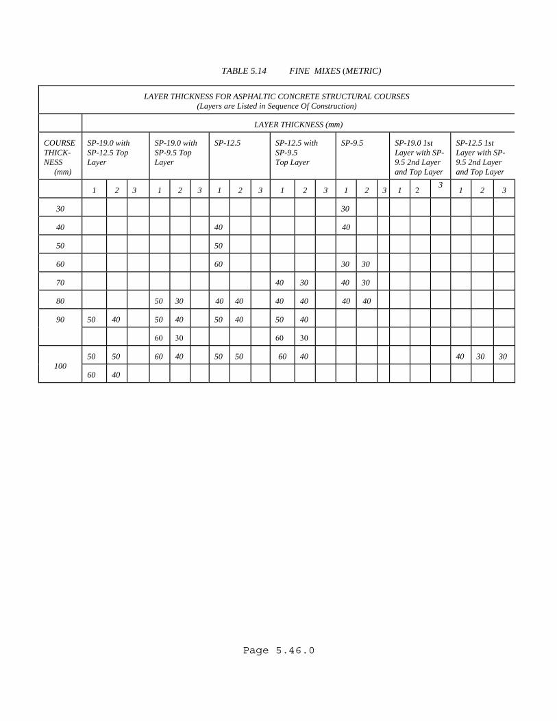
Page 5.46.0
TABLE 5.14 FINE MIXES (METRIC)
LAYER THICKNESS FOR ASPHALTIC CONCRETE STRUCTURAL COURSES
(Layers are Listed in Sequence Of Construction)
LAYER THICKNESS (mm)
COURSE THICK-NESS (mm)
SP-19.0 with SP-12.5 Top Layer
SP-19.0 with SP-9.5 Top Layer
SP-12.5
SP-12.5 with SP-9.5 Top Layer
SP-9.5
SP-19.0 1st Layer with SP-9.5 2nd Layer and Top Layer
SP-12.5 1st Layer with SP-9.5 2nd Layer and Top Layer
1
2
3
1
2
3
1
2
3
1
2
3
1
2
3
1
2
3 1
2
3
30
30
40
40
40
50
50
60
60
30
30
70
40
30
40
30
80
50
30
40
40
40
40
40
40
50
40
50
40
50
40
50
40
90
60
30
60
30
50
50
60
40
50
50
60
40
40
30
30
100 60
40
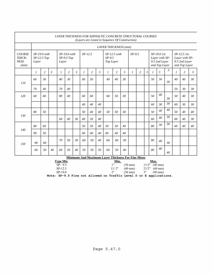
Page 5.47.0
LAYER THICKNESS FOR ASPHALTIC CONCRETE STRUCTURAL COURSES (Layers are Listed in Sequence Of Construction)
LAYER THICKNESS (mm)
COURSE THICK-NESS (mm)
SP-19.0 with SP-12.5 Top Layer
SP-19.0 with SP-9.5 Top Layer
SP-12.5
SP-12.5 with SP-9.5 Top Layer
SP-9.5
SP-19.0 1st Layer with SP-9.5 2nd Layer and Top Layer
SP-12.5 1st Layer with SP-9.5 2nd Layer and Top Layer
1
2
3
1
2
3
1
2
3
1
2
3
1
2
3
1
2
3 1
2
3
60
50
80
30
60
50
40
40
30
50
30
30
40
40
30
110 70
40
70
40
50
30
30
60
60
80
40
60
60
60
50
30
50
40
30
50
40
30
120
40
40
40
60
30 30
60 30
30
80
50
50
40
40
50
50
30
50
40 40
50 40
40
130
60
40
30
60
50
40
60
40 30
60 40
30
80
60
50
50
40
50
50
40
80
30 30
60 40
40
140 90
50
60
40
40
60
40
40
90
60
70
50
30
60
50
40
60
60
30
80
40
30
150 60
50
40
60
50
40
50
50
50
60
50
40
80
40
40
Minimum And Maximum Layer Thickness For Fine Mixes Type Mix Min. Max.
SP- 9.5 1" (30 mm) 11/2" (40 mm) SP-12.5 11/ 2" (40 mm) 21/2" (60 mm)
SP-19.0 2" (50 mm) 3" (90 mm) Note: SP-9.5 Fine not allowed on Traffic Level D or E applications.
Page 5.48.0
5. 5. 7 RAMP DESIGN On new construction of limited access ramps, where future traffic is very uncertain, the structural number can be reduced by 25% from the mainline structural number in rural areas, and 15% in urban areas. The reduction in structural number will be made in the thickness of the structural course. A minimum Base Group 9 and 2"(50 mm) structural course should be provided. The transition from mainline thickness to ramp thickness will occur just beyond the gore.(See Standard Index 525, Ramp Terminals). The design assumptions used for the above guidelines were based on 25% of the mainline traffic using the ramp in rural areas and 50% of the mainline traffic using the ramp in urban areas. The Pavement Design Engineer must verify that these assumptions are appropriate for each project. A situation where the designer would not want to reduce the design, would be a case where reliable traffic data has been provided and the design thickness is larger than the reduced thickness.
Page 5.49.0
(THIS PAGE HAS BEEN LEFT INTENTIONALLY BLANK)
Page 6.1.0
CHAPTER 6 PAVEMENT THICKNESS DESIGN PROCESS FOR
REHABILITATION PROJECTS 6.1 OVERVIEW This process is applicable to all rehabilitation projects in Florida where the Pavement Design Engineer must calculate a structural overlay thickness using the AASHTO procedure. The following steps will take place in approximately the order shown with the understanding that some activities can take place concurrently. A schematic of the process is shown in Figure 6.1. 6.2 REQUIRED STRUCTURAL NUMBER (SNR) CALCULATIONS
USING THE AASHTO GUIDE The procedure for calculating the Required Structural Number (SNR) is the same method detailed under New Construction (Refer to Section 5.2). 6.3 RESILIENT MODULUS (MR) VARIATIONS Rehabilitation projects use the existing subgrade soils. This material may be variable within a project for several reasons. One reason for subgrade variability may be that different parts of the project were constructed under several earlier projects. Other variability may be due to factors such as soil strata, compaction, and moisture content. Two methods of obtaining the Resilient Modulus (MR) values are available to the Pavement Design Engineer. These are non-destructive testing using the Deflection Equipment, and Soil Test Data . This information needs to be obtained as early as possible in the design process.
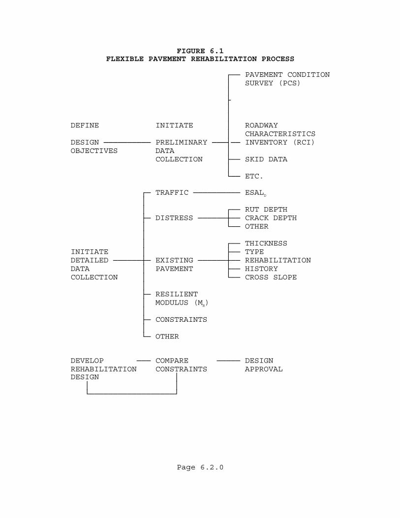
Page 6.2.0
FIGURE 6.1 FLEXIBLE PAVEMENT REHABILITATION PROCESS ┌── PAVEMENT CONDITION │ SURVEY (PCS) │ ├ │ │ DEFINE INITIATE │ ROADWAY │ CHARACTERISTICS DESIGN ────────── PRELIMINARY ───┤── INVENTORY (RCI) OBJECTIVES DATA │ COLLECTION ├── SKID DATA │ └── ETC. ┌─ TRAFFIC ────────── ESALD
│ │ ┌── RUT DEPTH ├─ DISTRESS ──────┼── CRACK DEPTH │ └── OTHER │ │ ┌── THICKNESS INITIATE │ ├── TYPE DETAILED ──────┼─ EXISTING ──────┼── REHABILITATION DATA │ PAVEMENT ├── HISTORY COLLECTION │ └── CROSS SLOPE │ ├─ RESILIENT │ MODULUS (MR) │ ├─ CONSTRAINTS │ └─ OTHER DEVELOP ─── COMPARE ───── DESIGN REHABILITATION CONSTRAINTS APPROVAL DESIGN │ │ │ └──────────────────┘

Page 6.3.0
6.3.1 RESILIENT MODULUS (MR) FROM NONDESTRUCTIVE TESTING
Nondestructive Deflection testing is the preferred method for obtaining the Resilient Modulus(MR) for a rehabilitation project. The deflection values obtained represents the deflection of the embankment or natural subgrade material. More test data can be collected and used to statistically calculate the Resilient Modulus(MR). A plot of the actual deflection data permits the Pavement Design Engineer to evaluate the uniformity of the material under the existing roadway. The State Materials Office will provide an evaluation of the deflections and will provide one or more recommended Resilient Modulus(MR) values for the project. The design Resilient Modulus(MR) represents the weakest area within the design limits that it is practical to design for. It is based on the mean deflection plus two standard deviations and represents an optimum tradeoff between future isolated maintenance costs and increased overlay costs. This analysis is different than the Reliability factor(%R) which is used to account for traffic forecasting and construction variability. Significant variances that show up on the plots should warrant further investigation to determine if special attention must be paid to these areas or if the designs must be modified accordingly. Example plots are given in Figure 6.2, Figure 6.3, and Figure 6.4. Note that in Figure 6.2 the plot is constant compared to Figure 6.3 and Figure 6.4. In Figure 6.3, a significant change takes place in the Pavement Structure. In Figure 6.4, a "Blip" occurs in the plot warranting a field check. 6.3.2 RESILIENT MODULUS (MR) FROM LBR If it is not practical to obtain Deflection testing and a Design LBR Value is available, the Pavement Design Engineer can convert the Design LBR Value to a Resilient Modulus (MR) using Table 5.1.
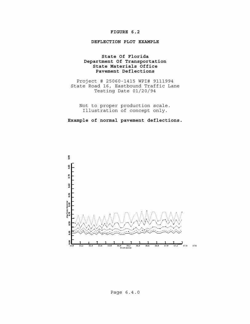
FIGURE 6.2 DEFLECTION PLOT EXAMPLE State Of Florida Department Of Transportation State Materials Office Pavement Deflections Project # 25060-1415 WPI# 9111994 State Road 16, Eastbound Traffic Lane
Testing Date 01/20/94
Not to proper production scale. Illustration of concept only.
Example of normal pavement deflections.
15.0 15.2 15.4 15.6 15.8 16.0 16.2 16.4 16.6 16.8 17.0 17.2 17.4 17.6Distance
Page 6.4.0
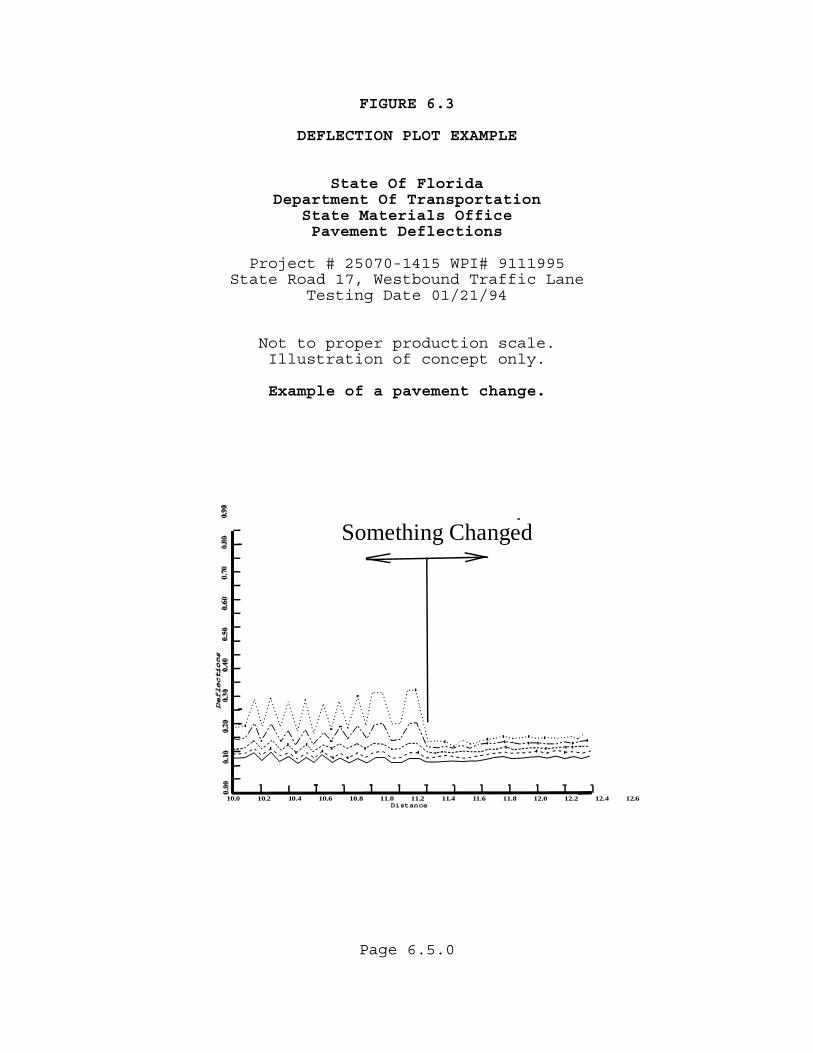
FIGURE 6.3 DEFLECTION PLOT EXAMPLE State Of Florida Department Of Transportation State Materials Office Pavement Deflections Project # 25070-1415 WPI# 9111995 State Road 17, Westbound Traffic Lane Testing Date 01/21/94
Not to proper production scale. Illustration of concept only.
Example of a pavement change.
10.0 10.2 10.4 10.6 10.8 11.0 11.2 11.4 11.6 11.8 12.0 12.2 12.4 12.6Distance
Something Changed
Page 6.5.0
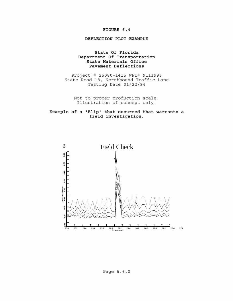
FIGURE 6.4 DEFLECTION PLOT EXAMPLE State Of Florida Department Of Transportation State Materials Office Pavement Deflections Project # 25080-1415 WPI# 9111996 State Road 18, Northbound Traffic Lane Testing Date 01/22/94
Not to proper production scale. Illustration of concept only.
Example of a 'Blip' that occurred that warrants a
field investigation.
25.0 25.2 25.4 25.6 25.8 26.0 26.2 26.4 26.6 26.8 27.0 27.2 27.4 27.6Distance
Field Check
Page 6.6.0
Page 6.7.0
6.4 EVALUATING THE EXISTING STRUCTURAL NUMBER
(SNE) Many items must be examined before the proper rehabilitation strategy can be initiated. After these items are reviewed, action by the Pavement Design Engineer is important to meet production schedules. 6.4.1 FIELD TESTING The Pavement Design Engineer must determine what the project is to accomplish. Some jobs, such as skid hazard, widening, or operational type projects, are not designed structurally. They do not require a standard pavement thickness design and normally do not require deflection testing unless an evaluation of the underlying materials is needed. Testing is not feasible for extremely short projects due to the reduction in the normal testing frequency and testing confidence limits. Deflection testing requests should not be made for: • Two lane roadway projects less than 1 mile (1.5 km) long. • Three lanes or more roadway projects less than 0.5 miles
(0.8 km) long. Example projects where Deflection testing should not be required include bridge or culvert replacement, intersection improvement, etc. Scheduling the Maintenance Of Traffic (MOT) in order to accomplish this field testing requires close coordination between the State Materials Office and the District Maintenance Offices. It is highly recommended that the longest possible lead time be allowed to accomplish this field work. It is preferable to give the State Materials Office a year or more advance notice so that they can schedule their work throughout the state. A good time to do this is after the work program is updated and project schedules are set. Coordinated requests for multiple jobs within a district are preferred.

Page 6.8.0
6.4.2 DATA COLLECTION The goal of a Pavement Design Engineer is to provide a pavement structure that will maintain the desired serviceability over the design period at optimum cost. The design period will be between 8 and 20 years depending on the type of project the Pavement Design Engineer ultimately develops. The Pavement Design Engineer will need to initiate a preliminary data collection effort. Sources of information include the present and historical Pavement Condition Survey (PCS). Additional information can be obtained from the Roadway Characteristics Inventory (RCI), Straight Line Diagrams (SLD), and old plans. The Design Survey Information should be obtained so that existing pavement cross slope can be checked. Documentation is also available from the District Materials, Drainage, Maintenance, and Construction personnel who have knowledge of, and are interested in the project. A field review of the project is recommended to verify the project information and ensure that the design objectives have been properly defined. The year of last rehabilitation, condition of the pavement before the last rehabilitation, and the type of rehabilitation performed should be documented in the pavement design package.
Page 6.9.0
6.4.3 PAVEMENT EVALUATION The pavement evaluation information should be used by the designer to carefully evaluate the possible causes of the current distress, so that the distresses are not simply repaired, but are also prevented from rapidly recurring. The designer should not be satisfied with simply providing an adequate structural number, but should also consider other factors. An example would be an unstable lower layer that has repeatedly contributed to rutting in the past. By studying the pavement history, this problem could be identified and evaluated and a deeper milling depth set. A concrete overlay or reconstruction to concrete are other alternatives to consider. The District Materials Office should be requested to perform an evaluation of the project. Deflection data should be reviewed to see if special areas of investigation are warranted. Pavement Coring and Evaluation Procedure, Materials Manual Section 3.4 can be obtained from the State Materials Office or through the departments INTERNET and INTRANET sites. Specific pavement data required includes the existing material type and thickness, the quality and condition of the materials, and the cross slope. Research on the existing pavement should also include researching old plans for existing stabilization. If the existing plans are not available, additional testing to determine the need for stabilization on widening and/or shoulder pavement may be needed. Specific detailed distress data needed at this time includes, type and extent of cracking, crack depths, cross slope, and rut depth. The District Materials Office will provide recommendations on milling, leveling, overbuild, use of automatic screed control, and an Asphalt Rubber Membrane Interlayer (ARMI) when required.
Page 6.10.0
6.4.4 REDUCED LAYER COEFFICIENTS When a pavement has been in service for some time, it can be demonstrated that the asphaltic materials will have lost some of their load carrying ability. To represent this in the Existing Structural Number (SNE) calculations, a set of reduced layer coefficients reflecting the current pavement condition to be used for rehabilitation projects have been tabulated. These values are given in Table 6.1. Granular base, subbase, and stabilizing, if present in the pavement structure, are assumed to remain at full strength and are not reduced in the Existing Structural Number (SNE) calculations. If substandard materials are suspected, the State Materials Office should be requested to do an evaluation and possibly recommend a lower value. The Existing Structural Number (SNE) can be calculated using the following formula:
SNE = (a1 x D1) + (a2 x D2) + (a3 x D3) + ... + (aN x DN)
where:
SNE = Total strength of the existing pavement layers.
a1 = Reduced layer coefficient of the 1st layer. D1 = Layer thickness of the 1st layer. a2 = etc. D2 = etc. aN = Layer coefficient of the Nth layer. DN = Layer thickness in millimeters of the Nth layer.
If a pavement is to be milled, the thickness of the uppermost layers affected by the milling operation will be eliminated. The layer coefficients for asphaltic materials are reduced as shown in Table 6.1, based on the condition of the pavement. Pavement Condition should be based on the surface appearance of the pavement (cracking, patching, rutting, etc.) and may be supplemented by additional testing.
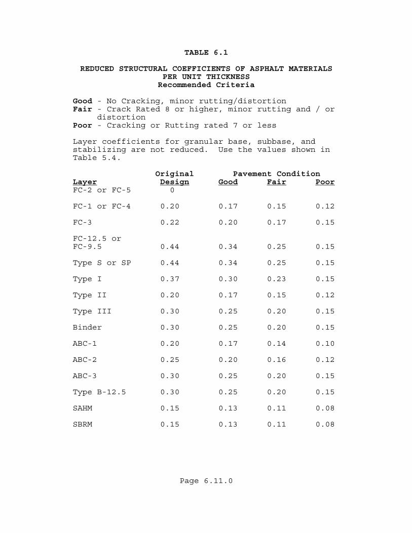
Page 6.11.0
TABLE 6.1 REDUCED STRUCTURAL COEFFICIENTS OF ASPHALT MATERIALS PER UNIT THICKNESS Recommended Criteria Good - No Cracking, minor rutting/distortion Fair - Crack Rated 8 or higher, minor rutting and / or distortion Poor - Cracking or Rutting rated 7 or less Layer coefficients for granular base, subbase, and stabilizing are not reduced. Use the values shown in Table 5.4.
Original Pavement Condition Layer Design Good Fair PoorFC-2 or FC-5 0 FC-1 or FC-4 0.20 0.17 0.15 0.12 FC-3 0.22 0.20 0.17 0.15 FC-12.5 or FC-9.5 0.44 0.34 0.25 0.15 Type S or SP 0.44 0.34 0.25 0.15 Type I 0.37 0.30 0.23 0.15 Type II 0.20 0.17 0.15 0.12 Type III 0.30 0.25 0.20 0.15 Binder 0.30 0.25 0.20 0.15 ABC-1 0.20 0.17 0.14 0.10 ABC-2 0.25 0.20 0.16 0.12 ABC-3 0.30 0.25 0.20 0.15 Type B-12.5 0.30 0.25 0.20 0.15 SAHM 0.15 0.13 0.11 0.08 SBRM 0.15 0.13 0.11 0.08
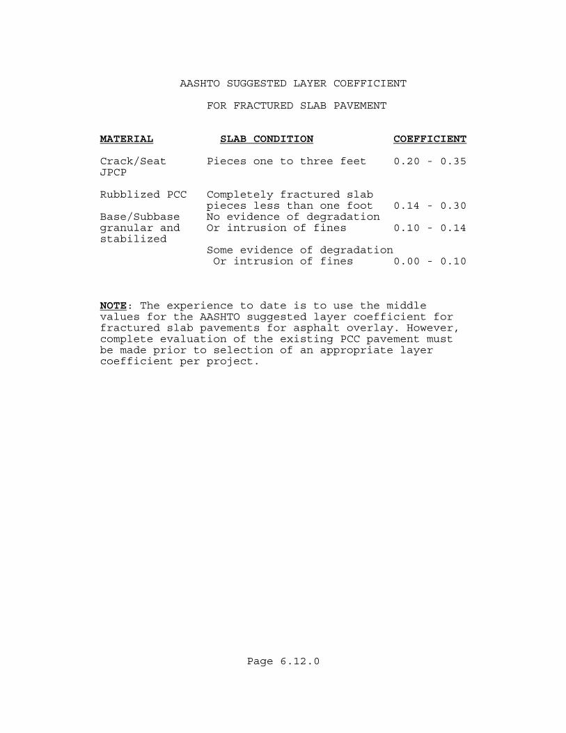
Page 6.12.0
AASHTO SUGGESTED LAYER COEFFICIENT
FOR FRACTURED SLAB PAVEMENT
MATERIAL SLAB CONDITION COEFFICIENT Crack/Seat Pieces one to three feet 0.20 - 0.35 JPCP Rubblized PCC Completely fractured slab pieces less than one foot 0.14 - 0.30 Base/Subbase No evidence of degradation granular and Or intrusion of fines 0.10 - 0.14 stabilized Some evidence of degradation Or intrusion of fines 0.00 - 0.10 NOTE: The experience to date is to use the middle values for the AASHTO suggested layer coefficient for fractured slab pavements for asphalt overlay. However, complete evaluation of the existing PCC pavement must be made prior to selection of an appropriate layer coefficient per project.
Page 6.13.0
6.5 MILLING The need to mill all or part of the existing pavement should be evaluated for every project. A decision to mill should be based on sound economic and engineering principles. Consideration should also be given to the time between coring and evaluation of the project, and the construction phase of the project. If the project is cored and evaluated but not constructed for several years, the pavement conditions in the Pavement Evaluation may change significantly. 6.5.1 CANDIDATE PROJECTS Milling may be appropriate for the following reasons: • Remove badly cracked asphalt. • To correct cross-slope. • Avoid raising the grade excessively (ie. curb and
gutter sections, bridges, underpasses, etc.). • To remove rut susceptible mixes. • Minimize the need to perform construction work
outside the mainline pavement area, (an example would be requiring a structurally unnecessary overlay of paved shoulders plus safety work and earthwork).
• Elimination of an existing mix problem that should be removed rather than be overlaid.
• In lieu of leveling. • For removal of FC-2 or FC-5 when overlaying. • If the overall project cost would be less with
milling than without. Cracked pavement should be milled out where possible to avoid reflective cracking in the overlay. It is usually desirable to leave at least 3/4"(20 mm) of asphalt over the base throughout the project to protect it from traffic and rain. However, the entire asphalt structure can be milled out as long as contract provisions provide for maintenance of traffic and protection of the base, such as placement of the first lift of structural asphalt the same day of the milling operation, or the use of prime coat. Consideration should also be given to underlying layers that may consist of potentially unstable materials that could cause problems if exposed by milling (such as some old low asphalt content binder courses or low Marshall stability mixes). If these situations exist, they should be carefully discussed with the District Bituminous Engineer and the Roadway Design Engineer.
Page 6.14.0
Special Provisions may be needed to limit the exposure of these layers to traffic until adequate structural thickness is placed. Distress in an overlay due to reflective cracking is not fully modeled in the structural number calculations. Research is being done to better evaluate reflective cracking potential using computer modeling. If it is not practical to mill out most of the cracked pavement, an Asphalt Rubber Membrane Interlayer (ARMI) and/or additional overlay thickness should be considered. Generally it is not practical to mill to a depth greater than 5"(120 mm). Use of Asphalt Rubber Membrane Interlayer (ARMI) is discussed further in section 6.8.5. Milling is not the solution when the base or subgrade is the problem. An evaluation should be made of the base or subgrade to determine if reconstruction is necessary. 6.5.2 COMPOSITION REPORTS If greater than 5000 tons of the same pavement structure is milled, a composition of the existing pavement should be prepared and placed on the Internet by the State Materials Office. The composition report is now available on the Internet at: http://www.dot.state.fl.us/statematerialsoffice/laboratory/Centrallaboratory/Compositions/index.htm A Composition Report is not needed when milling FC-2 or FC-5 only. This is primarily due to the thickness of the layer i.e.1/2" or 3/4"(15 or 20 mm) and the small amount of material to do an analysis on. Coring for structural information is still recommended, even if a composition report is not required. If the milling depth varies from point to point (ie. lane to lane, site to site), the composition reports must reflect this change.
Page 6.15.0
6.5.3 VARIABLE DEPTH MILLING Under some conditions, variable depth milling may be appropriate. As an example, cracks in a truck lane may be significantly deeper than cracks in the passing lane. This must be coordinated closely with construction. This must be reflected in the composition reports. The milling depth should be uniform within a lane except when the milling slope has been set to correct a cross slope problem. 6.5.4 CROSS-SLOPE Proper pavement cross-slope is essential to provide adequate drainage, especially if minor rutting occurs on the pavement. The Pavement Design Engineer should work closely with the District Bituminous Engineer to ensure cross-slope is addressed in design. Existing cross-slope should be checked from the Design Survey and from the cross-slope measurements shown on the Pavement Evaluation and Coring Report. If a Design Survey has not been made and cross-slope problems are suspected, then a survey should be requested according to Survey Guidelines for RRR Projects (section 25.3.4 of the Plans Preparation Manual (PPM)Vol.1) If the existing cross-slope is not adequate, sufficient overbuild material must be provided by the Roadway Designer in the quantity estimate to correct the deficiency. The District Bituminous Engineer will provide recommendations with regard to specifying the use of transverse screed control for the paver. Milling to a specified cross slope should also be considered. If correction to the cross-slope is needed, the pavement designer should discuss possible corrective actions with the District Bituminous Engineer and the Roadway Design Engineer to ensure constructability. Special milling and layering details shall be shown in the plans when cross-slope correction is needed.
Page 6.16.0
The milling depth should be uniform within a lane except when the milling slope has been set to correct a cross slope problem. If the longitudinal profile is also to be corrected, sufficient leveling or overbuild materials must be provided in the estimate. If rutting has been a problem in an area, careful consideration should be given to the feasibility of increasing the cross-slope to 3% on highways with high truck volumes. This will extend the pavement life considerably if rutting is the principal cause of distress. 6.5.5 RUTTED PAVEMENT The rehabilitation technique to be applied to a rutted pavement must be carefully evaluated. If rutting was caused by age and consolidation, it may be more economical to level and overlay. If the pavement is relatively young and rutting is a major form of distress, there may be a materials or mix problem. Milling of the substandard material may be essential. The history of the pavement should be studied to see if unstable mixes previously existed and need to be removed. For a pavement that is rutted and not cracked, a special evaluation should be made prior to a decision on the depth of milling. The State Materials Office should be contacted and their assistance requested to determine if milling would be prudent. Special tests on various layers and cross sectional coring or trenching may be warranted to identify problem layers in the top 5"(120 mm) of pavement.
Page 6.17.0
6.5.6 BINDER SELECTION ON THE BASIS OF TRAFFIC
SPEED AND TRAFFIC LEVEL. By specification, the standard asphalt binder grade is a PG 67-22, which means the binder should be rut resistant up to temperatures of 67˚C (153˚F) and crack resistant down to temperatures of –22˚C (-8˚F). The resilient Modulus of asphalt concrete is less under a slow moving load than under a more dynamic, high speed load. As a result of this effect, slow moving or stopped trucks have a greater potential to cause rutting. In high traffic levels and slow moving or standing truck traffic and particularly those sections with a history of rutting, asphalt concrete mixes containing modified binder PG 76-22 with more stiffness at higher temperatures will provide more rut resistance than asphalt mixes with a standard asphalt binder. Examples For toll booths, intersections with slow truck traffic, pavement sections with history of rutting and weigh stations with standing traffic, use a PG 76-22 asphalt binder. A minimum of 1000 tons of modified structural mix is generally recommended per project or group of projects to make the most efficient use of the material. For high traffic levels D and E, use PG 76-22 asphalt binder in the final structural layer for traffic level D and for the top two structural layers for traffic level E. The PG 76-22 layer spread rate should be shown separately on the typical section and a separate pay item used.
Page 6.18.0
If FC-12.5 is needed on a traffic level D or E project, a plan note should be added to designate the traffic level for the friction course and PG 76-22 called for in the friction course. This is necessary since the structural friction courses are level C by specification, unless shown otherwise in the plans. For a Traffic Level D and E FC-9.5 (Fine mix not allowed). 6.5.7 MILLING DEPTH The District Bituminous Engineer and the District Pavement Design Engineer will set the milling depth based on field data that is collected using the Pavement Coring and Evaluation Guidelines. It should be noted that laboratory testing of the project field cores can not be completed until the milling depths have been set. The cores are then cut and tested to provide a composition report for the Recycled Asphalt Pavement (RAP). This must be taken into consideration with the timing of these various operations. A composition report should be prepared by the State Materials Office and placed on the web for any project with milled material quantities over 5000 tons from the same general pavement structure.
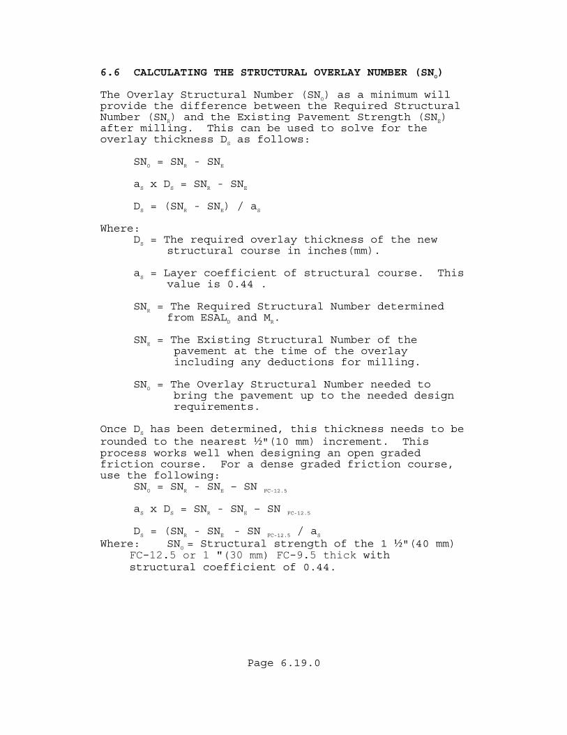
Page 6.19.0
6.6 CALCULATING THE STRUCTURAL OVERLAY NUMBER (SNO) The Overlay Structural Number (SNO) as a minimum will provide the difference between the Required Structural Number (SNR) and the Existing Pavement Strength (SNE) after milling. This can be used to solve for the overlay thickness DS as follows:
SNO = SNR - SNE
aS x DS = SNR - SNE
DS = (SNR - SNE) / aS
Where:
DS = The required overlay thickness of the new structural course in inches(mm).
aS = Layer coefficient of structural course. This value is 0.44 .
SNR = The Required Structural Number determined from ESALD and MR.
SNE = The Existing Structural Number of the pavement at the time of the overlay including any deductions for milling.
SNO = The Overlay Structural Number needed to
bring the pavement up to the needed design requirements. Once DS has been determined, this thickness needs to be rounded to the nearest ½"(10 mm) increment. This process works well when designing an open graded friction course. For a dense graded friction course, use the following:
SNO = SNR - SNE – SN FC-12.5
aS x DS = SNR - SNE – SN FC-12.5
DS = (SNR - SNE - SN FC-12.5 / aS
Where: SNO = Structural strength of the 1 ½"(40 mm) FC-12.5 or 1 "(30 mm) FC-9.5 thick with structural coefficient of 0.44.
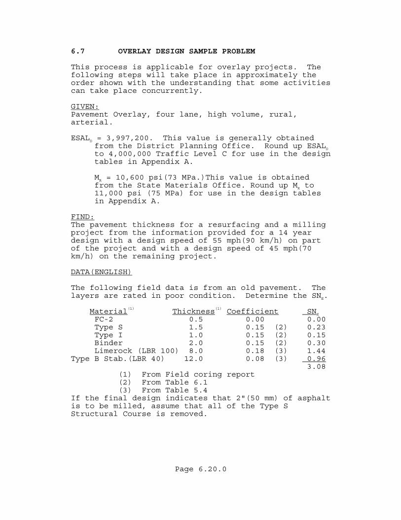
Page 6.20.0
6.7 OVERLAY DESIGN SAMPLE PROBLEM This process is applicable for overlay projects. The following steps will take place in approximately the order shown with the understanding that some activities can take place concurrently. GIVEN:Pavement Overlay, four lane, high volume, rural, arterial. ESALD = 3,997,200. This value is generally obtained
from the District Planning Office. Round up ESALD to 4,000,000 Traffic Level C for use in the design tables in Appendix A.
MR = 10,600 psi(73 MPa.)This value is obtained from the State Materials Office. Round up MR to 11,000 psi (75 MPa) for use in the design tables in Appendix A.
FIND:The pavement thickness for a resurfacing and a milling project from the information provided for a 14 year design with a design speed of 55 mph(90 km/h) on part of the project and with a design speed of 45 mph(70 km/h) on the remaining project. DATA(ENGLISH) The following field data is from an old pavement. The layers are rated in poor condition. Determine the SNE. Material(1) Thickness(1) Coefficient SNE
FC-2 0.5 0.00 0.00 Type S 1.5 0.15 (2) 0.23 Type I 1.0 0.15 (2) 0.15 Binder 2.0 0.15 (2) 0.30 Limerock (LBR 100) 8.0 0.18 (3) 1.44
Type B Stab.(LBR 40) 12.0 0.08 (3) 0.96 3.08
(1) From Field coring report (2) From Table 6.1 (3) From Table 5.4
If the final design indicates that 2"(50 mm) of asphalt is to be milled, assume that all of the Type S Structural Course is removed.
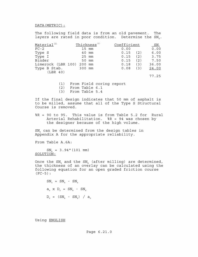
Page 6.21.0
DATA(METRIC): The following field data is from an old pavement. The layers are rated in poor condition. Determine the SNE. Material(1) Thickness(1) Coefficient SNE
FC-2 15 mm 0.00 0.00 Type S 40 mm 0.15 (2) 6.00 Type I 25 mm 0.15 (2) 3.75 Binder 50 mm 0.15 (2) 7.50 Limerock (LBR 100) 200 mm 0.18 (3) 36.00 Type B Stab. 300 mm 0.08 (3) 24.00 (LBR 40) 77.25
(1) From Field coring report (2) From Table 6.1 (3) From Table 5.4
If the final design indicates that 50 mm of asphalt is to be milled, assume that all of the Type S Structural Course is removed. %R = 90 to 95. This value is from Table 5.2 for Rural
Arterial Rehabilitation. %R = 94 was chosen by the designer because of the high volume.
SNR can be determined from the design tables in Appendix A for the appropriate reliability. From Table A.6A:
SNR = 3.94"(101 mm) SOLUTION: Once the SNR and the SNE (after milling) are determined, the thickness of an overlay can be calculated using the following equation for an open graded friction course (FC-5):
SNO = SNR - SNE
aS x DS = SNR - SNE
DS = (SNR - SNE) / aS
Using ENGLISH
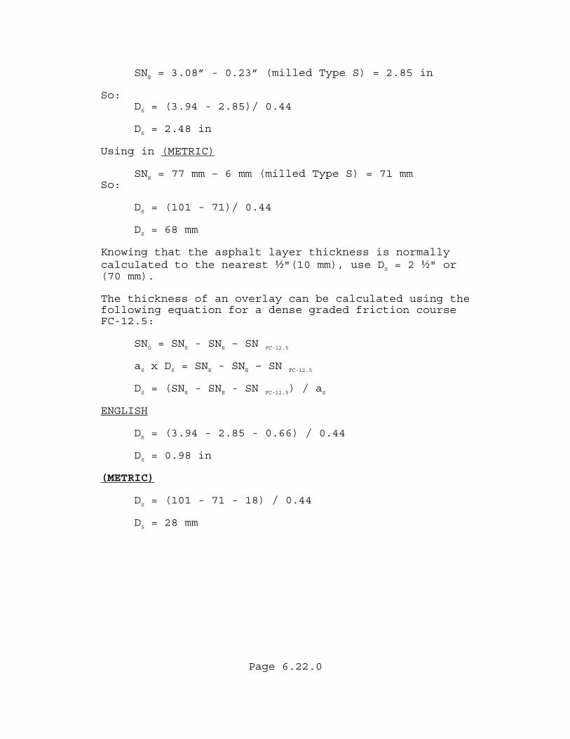
Page 6.22.0
SNE = 3.08” - 0.23” (milled Type S) = 2.85 in So:
DS = (3.94 - 2.85)/ 0.44
DS = 2.48 in Using in (METRIC)
SNE = 77 mm – 6 mm (milled Type S) = 71 mm So:
DS = (101 - 71)/ 0.44
DS = 68 mm Knowing that the asphalt layer thickness is normally calculated to the nearest ½"(10 mm), use DS = 2 ½" or (70 mm). The thickness of an overlay can be calculated using the following equation for a dense graded friction course FC-12.5:
SNO = SNR - SNE – SN FC-12.5 aS x DS = SNR - SNE – SN FC-12.5
DS = (SNR - SNE - SN FC-12.5) / aS
ENGLISH DS = (3.94 - 2.85 - 0.66) / 0.44
DS = 0.98 in (METRIC)
DS = (101 - 71 - 18) / 0.44
DS = 28 mm
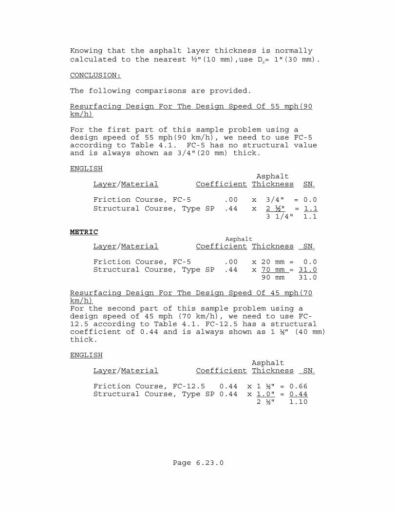
Page 6.23.0
Knowing that the asphalt layer thickness is normally calculated to the nearest ½"(10 mm),use DS= 1"(30 mm). CONCLUSION: The following comparisons are provided. Resurfacing Design For The Design Speed Of 55 mph(90 km/h) For the first part of this sample problem using a design speed of 55 mph(90 km/h), we need to use FC-5 according to Table 4.1. FC-5 has no structural value and is always shown as 3/4"(20 mm) thick. ENGLISH Asphalt
Layer/Material Coefficient Thickness SNO
Friction Course, FC-5 .00 x 3/4" = 0.0 Structural Course, Type SP .44 x 2 ½" = 1.1
3 1/4" 1.1 METRIC Asphalt
Layer/Material Coefficient Thickness SNO
Friction Course, FC-5 .00 x 20 mm = 0.0 Structural Course, Type SP .44 x 70 mm = 31.0
90 mm 31.0 Resurfacing Design For The Design Speed Of 45 mph(70 km/h)For the second part of this sample problem using a design speed of 45 mph (70 km/h), we need to use FC-12.5 according to Table 4.1. FC-12.5 has a structural coefficient of 0.44 and is always shown as 1 ½” (40 mm) thick. ENGLISH Asphalt
Layer/Material Coefficient Thickness SNO
Friction Course, FC-12.5 0.44 x 1 ½" = 0.66 Structural Course, Type SP 0.44 x 1.0" = 0.44
2 ½" 1.10
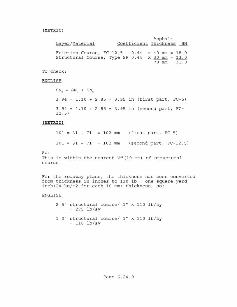
Page 6.24.0
(METRIC) Asphalt
Layer/Material Coefficient Thickness SNO
Friction Course, FC-12.5 0.44 x 40 mm = 18.0 Structural Course, Type SP 0.44 x 30 mm = 13.0
70 mm 31.0 To check: ENGLISH
SNR = SNO + SNE
3.94 = 1.10 + 2.85 = 3.95 in (first part, FC-5) 3.94 = 1.10 + 2.85 = 3.95 in (second part, FC-12.5)
(METRIC)
101 = 31 + 71 = 102 mm (first part, FC-5)
101 = 31 + 71 = 102 mm (second part, FC-12.5) So: This is within the nearest ½"(10 mm) of structural course. For the roadway plans, the thickness has been converted from thickness in inches to 110 lb = one square yard inch(24 kg/m2 for each 10 mm) thickness, so: ENGLISH 2.5” structural course/ 1” x 110 lb/sy
= 275 lb/sy
1.0” structural course/ 1” x 110 lb/sy
= 110 lb/sy
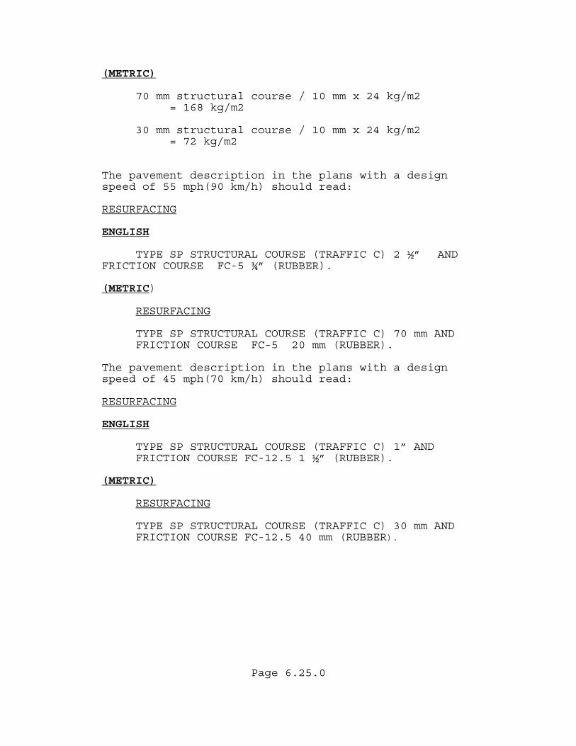
Page 6.25.0
(METRIC)
70 mm structural course / 10 mm x 24 kg/m2 = 168 kg/m2
30 mm structural course / 10 mm x 24 kg/m2
= 72 kg/m2 The pavement description in the plans with a design speed of 55 mph(90 km/h) should read: RESURFACING ENGLISH
TYPE SP STRUCTURAL COURSE (TRAFFIC C) 2 ½” AND FRICTION COURSE FC-5 ¾” (RUBBER). (METRIC)
RESURFACING
TYPE SP STRUCTURAL COURSE (TRAFFIC C) 70 mm AND FRICTION COURSE FC-5 20 mm (RUBBER).
The pavement description in the plans with a design speed of 45 mph(70 km/h) should read: RESURFACING ENGLISH
TYPE SP STRUCTURAL COURSE (TRAFFIC C) 1” AND FRICTION COURSE FC-12.5 1 ½” (RUBBER).
(METRIC)
RESURFACING
TYPE SP STRUCTURAL COURSE (TRAFFIC C) 30 mm AND FRICTION COURSE FC-12.5 40 mm (RUBBER).
Page 6.26.0
6.8 SPECIAL CONSIDERATIONS FOR REHABILITATION PROJECTS It is essential that the Pavement Design Engineer coordinate very closely with all of the offices that will be affected by the work. It is highly recommended that field reviews of projects be made in a timely fashion. If appropriate, the State Pavement Management Office is available to assist on complex projects where statewide experience may be of value. 6.8.1 PAYMENT OF STRUCTURAL COURSE It is the Department's policy to pay for all structural and friction course asphalt items by the ton. One of the reasons that this is done is due to the amount of material that may be needed for irregular shaped areas (i.e. transitions, driveways, intersections, etc.) in which the quantities are hard to determine.
Page 6.27.0
6.8.2 LEVELING AND OVERBUILD The District Materials Office should be consulted for recommendations with respect to leveling and overbuild, taking into consideration existing pavement condition and cross slope. The following minimum values recommended by the State Materials Office are; • Leveling by specification is placed by a motor
grader and is used to provide a level surface prior to placing the structural course.
• Overbuild by specification is placed by a paving machine and is used to provide proper cross-slope and longitudinal profile. Only fine SP mixes are allowed.
• SP-9.5 Overbuild, minimum average uniform thickness with or without a structural course is 1” (30 mm).
• SP-9.5 Leveling, minimum average thickness is ½” (15 mm) and not more than 3/4” (20 mm) per layer.
• For Overbuild greater than 1 1/2” (40 mm), Type SP-
12.5 may be used. • Use the minimum and maximum layer thickness as noted
in section 5.5.6 for uniform thickness overbuild layers.
• All overbuild layers shall be Type SP Asphalt
Concrete. On variable thickness overbuild layers, the minimum allowable thickness may be reduced by
1/2"(10 mm) and the maximum allowable thickness may be increased 1/2"(10 mm). 6.8.3 OPERATIONAL PROJECTS On resurfacing projects such as skid hazard, intersection improvements, etc., where only a minimum amount of overbuild and (FC-5) are required, and no structural course is provided, the plans should specify: "TYPE SP 9.5 (TRAFFIC C) OVERBUILD 1” Average Overbuild should be specified rather than leveling because overbuild is placed with a paver, whereas leveling is placed using motor graders.
Page 6.28.0
FC-5 can be placed directly on the milled surface provided the underlying layers are in good structural shape. Projects using FC-5 without a structural course (such as Skid Hazard projects) where the existing roadway structural course is in good condition, might include projects: • With little or no cracking. • No structural improvement is required. • Minimum distortion and rutting are observed. • A need for motor grader applied leveling does not
exist. Friction course selection should continue to be in accordance with current Friction Course Policy. 6.8.4 FUNCTIONAL OVERLAYS On an older road that has been resurfaced several times, the computations may indicate that no added structural course is required. In this case the Pavement Design Engineer should remedy the problem by using the minimum amount of material appropriate for the distress. This should include a subjective consideration of reflective cracking potential that is not accounted for by structural number calculations. If the ride of the existing pavement is poor, it may be desirable to provide sufficient structural asphalt to restore a smooth ride. Milling, prior to overlay can also help improve the ride. The District Bituminous Engineer should be consulted for a recommendation in these cases. Document the basis for the overlay thickness and don't worry about exceeding the theoretical structural number requirements.

Page 6.29.0
6.8.5 CRACK RELIEF LAYERS The use of an Asphalt Rubber Membrane Interlayer (ARMI) as a crack relief layer and/or additional overlay thickness, may be necessary if insufficient material, cross slope, or other problems limit milling to remove cracked pavement. An ARMI should normally be used over cracked and reseated concrete pavement. An ARMI may also be useful as a moisture barrier if subgrade moisture is entering the pavement system through capillary action and causing a rippling of the asphalt surface. The District Bituminous Engineer should be consulted for a recommendation on when an ARMI layer is needed. Cracks left in underlying layers will reflect up through overlays due to stress concentrations at the cracks from temperature movement and load deflections. This can cause the overlay to deteriorate faster than would be indicated strictly by structural number calculations. To provide sufficient design life for an overlay over cracked pavement, it is often necessary to use an ARMI layer with at least a minimum structural overlay thickness based on the type of vehicle loadings. The ARMI layer helps to reduce the stress concentrations while the structural thickness will reduce deflections and help insulate the cracked pavement to reduce temperature movements. Research is underway to develop computer models to better estimate the additional design life that an ARMI will provide for a specific pavement. Until this research is complete, the Pavement Design Engineer will have to use engineering judgment to estimate the additional life extension anticipated and then evaluate the cost effectiveness of the ARMI layer. The review of the performance history of the pavement and similar projects in the area can provide useful information on reflective crack propagation potential for a specific project.
Page 6.30.0
The ARMI must be covered prior to being opened to traffic or other action should be taken to prevent windshield breakage from loose cover material. The State Materials Office recommends that an ARMI should not be used under a relatively thin overlay due to its cost and the need for sufficient heat in the overlay to properly bond the ARMI with the overlay. A 1 1/2" (40 mm) minimum initial structural asphalt lift is required over the ARMI to provide this heat, with a 2"(50 mm) lift preferred. This will require that the initial lift thickness be specified on the plans. Special consideration should be given to construction sequencing if paved shoulders are being added. It is recommended that the State Materials Office, or the State Pavement Design Engineer be contacted if the Pavement Design Engineer is considering the use of a crack relief layer and has not had recent experience in the District in the use of these materials.

Page 6.31.0
(THIS PAGE HAS BEEN LEFT INTENTIONALLY BLANK)
Page 7.1.0
CHAPTER 7 PAVEMENT WIDENING 7.1 REQUIREMENTS Pavement widening, which includes trench widening, lane addition, and operational type projects, do not require thickness design calculations. The Pavement Design Engineer needs to determine what the existing pavement structure consists of, including any designed overlays. The widening section will be designed and constructed to match the existing plus overlay pavement. The total structural number of the widened section must equal or exceed the total mainline structural number. The following guidelines will assist in providing a well engineered design. 7.2 STRUCTURAL COURSE To provide for future milling, the asphalt thickness of the structural course of the widening should match or exceed the existing mainline asphalt plus any overlays planned as a part of the project. It may be impractical to match the existing pavement of an old road that has had numerous overlays. It is essential that the Pavement Design Engineer evaluate what will be left if there is a future milling operation that for some reason removes a substantial amount of asphalt. A 4” to 5” thickness of structural asphalt is a reasonable limit depending on truck volumes, for inside traffic lanes which have less truck use. On selected projects, it may be necessary to justify and use an Asphalt Base(B-12.5) for widening. However, with proper design it may be possible to take advantage of the potential economics of a granular base material and bid an Optional Base. Industry representatives and the Department's Construction Office indicate that the following procedure could be used to permit the construction of trench widening without requiring the use of a barricade.
Page 7.2.0
7.3 BASE AND SUBGRADE The strength of the widened section base material, as measured by its layer coefficient, must match or exceed the existing base strength. The Pavement Design Engineer must visualize what is left when future milling occurs to insure that the remaining structural numbers are compatible. Normally the top of the new base and the top of the old base should match to facilitate future milling. From the top of the existing base down, the widening structural number must be equal to or greater than the existing structural number (including any stabilized subgrade). On any type of widening project, the base options to be used may be specified by the Pavement Design Engineer and shown in the plans to ensure layer coefficients equal or greater than the existing base. 7.4 STABILIZATION Stabilization should be considered when adding lanes or shoulders and on some operational type projects. The use of stabilizing in trench widening strips is generally not recommended. When stabilization is eliminated, the reasons should be documented in the project file. When stabilization is not provided, single course base layers should not be used. 7.6 LEVELING The use of a leveling course should be evaluated with construction personnel. In some cases all leveling will be placed prior to the base widening being constructed. In other cases, it may be desirable to place the leveling over both the main roadway and the widening area to remove construction variances.
Page 7.3.0
DAY ONE • Cut a trench for that day's run. • Place the first layer of granular base in the
trench. • Compact and finish. • Check the density. • Place the second layer of granular base in the
trench. • Compact and grade to comply with Standard Index 600. DAY TWO
• Compact and finish second layer. • Construct Structural Layers. Standard Index 600 provides several optional treatments that could be utilized during the construction of a granular base. The Pavement Design Engineer must also consider the constructability of his design. It is highly recommended that widening projects be kept as simple as possible. If a granular base is to be used, it should be designed flush with the existing granular base. Asphalt structural layers will then be brought up to the top of the existing asphalt layers. Subsequent asphalt layers can then be constructed full width over the existing roadway and the widening. The purpose is to minimize the possibility of a longitudinal crack at this joint. On complicated projects, it is highly recommended that the District Construction Engineer and the Resident Construction Engineer be contacted and the project reviewed in detail.
Page 7.4.0
7.7 WIDENING DESIGN SAMPLE PROBLEM The following is a sample problem on widening that is commonly found. GIVEN: The existing two lane rural roadway Traffic Level C is to be milled 3"(70 mm) and resurfaced with 2.5"(60 mm) Type SP and 1.5"(40 mm) FC-12.5. The existing lanes are 11'(3.3 m) wide. The road needs to be brought up to current standards by widening the lane to 12'(3.6 m). FIND: The pavement design for widening to match the existing pavement plus resurfacing. List any assumptions. Sketch a possible layer construction sequence of the design, including resurfacing, widening, and shoulders, to insure constructability. DATA: Field data from the existing pavement as evaluated by the District Bituminous Engineer includes the following information.
Material Thickness Condition
FC-4 1" (25 mm) poor
Type S 2" (45 mm) poor
Type I 1" (25 mm) fair
Binder 2" (50 mm) fair
Limerock 10.5" (280 mm) good
Stabilization 12" (300 mm) good SOLUTION: The original plans and field inspection indicate that the area beyond the edge of pavement was stabilized to the shoulder point.
Page 7.5.0
The pavement design for the widening includes:
= 1.5"(40 mm) Friction course. 5.5"(140 mm) Structural course
= use 5.5"(140 mm) Structural Course and
1.5"(40 mm) Friction Course to match the total asphalt thickness after milling plus resurfacing
= + 2.5"(60 mm) Structural Course (New) + 1"(25 mm) Type I (Remaining)+ 2"(50 mm) Binder (Remaining)
Optional Base Group 10
= SNE (Limerock)
= (0.18 x 10.5"(280 mm))
= 1.89” or Optional Base Group 10 Existing stabilization is assumed. A construction sketch of the design is provided (See Figure 7.1) showing the widening structural layers. The pavement description in the plans should read:
WIDENING
OPTIONAL BASE GROUP 10, AND TYPE SP STRUCTURAL COURSE (TRAFFIC C) 5 ½” (140 mm) AND FRICTION COURSE FC-12.5 1 ½ mm (40 mm)(RUBBER)
Selection of optional base should result in material meeting or exceeding the structural strength of the existing material.
Page 7.6.0
The pavement design for the shoulder includes: Existing shoulder stabilization is adequate and traffic loadings are moderate. This results in using the minimums for design found in Table 5.5. Table 5.5 lists the following:
1"(30 mm) Structural Course
Optional Base Group 1 FC-12.5 is sufficient for the structural course. The resurfacing and widening design includes 5 ½” (140 mm) structural course on the widening, 2 ½” (60 mm) of structural course on the resurfacing and widening with 1 ½” (40 mm) of FC-12.5 Friction Course on top of existing, widening and shoulder. The shoulder design should be design as follows:
Friction Course FC-12.5 1 ½” (40 mm)
Optional Base Group 1 A construction sketch of the design is provided (See Figure 7.1) showing the shoulder structural layers. The pavement description in the plans should read:
SHOULDER
OPTIONAL BASE GROUP 1 AND FRICTION COURSE FC-12.5 1 ½” (40 mm) (RUBBER)
Note that the 12"(300 mm) Type B Stabilization is not included in the description since the existing stabilization is adequate.
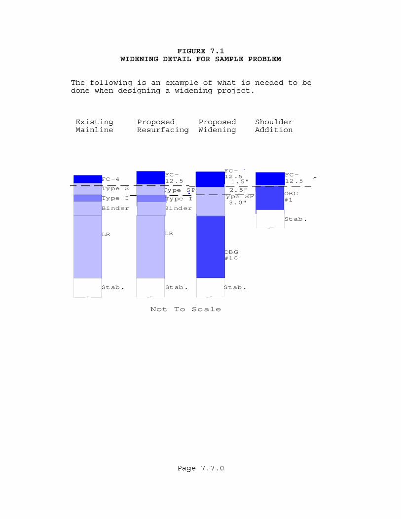
FIGURE 7.1 WIDENING DETAIL FOR SAMPLE PROBLEM
The following is an example of what is needed to be done when designing a widening project. Existing Proposed Proposed Shoulder Mainline Resurfacing Widening Addition
Not To Scale
Type S
FC-12.5
Type I
Binder
LR
Stab.Stab.
FC-4FC-12.5
Type SP3.0"
Type SP
Binder
LR
OBG#10
Type I
FC-12.5
OBG#1
Stab.
1.5"
2.5"
Stab.
Page 7.7.0

Page 7.8.0
(THIS PAGE HAS BEEN LEFT INTENTIONALLY BLANK)
Page 8.1.0
CHAPTER 8 SHOULDER DESIGN 8.1 DESIGN GUIDANCE On low volume roadways, shoulders can be designed using the minimum values shown in Table 5.5. A typical minimum design would be 1 ½” (40 mm) of FC-12.5 or 1” (30 mm) of FC-9.5 and Optional Base Group 1. For very low volume two lane roads (see table 4.1) a friction course may not be required. These minimums were established assuming a stabilized subgrade in conjunction with Optional Base Group 1. The pavement evaluation process will often indicate the shoulder was stabilized during original construction and additional stabilization is not needed. If stabilizing is not used under the shoulder, the Pavement Design Engineer must determine the type of materials in the embankment and evaluate the need for increasing the shoulder base and structural course. On higher type roadways (ESALD = 10 million or more), a shoulder thickness design may use 3% of the ESALD for the structural number calculated. This is an estimate of the number of trucks that will be riding or parking on the shoulder during the life of the pavement. If the shoulders are to be used to carry substantial amounts of traffic as a part of a Maintenance Of Traffic (MOT) scheme, the Pavement Design Engineer may need to design the shoulder in the same manner as a roadway. Under severe conditions, full depth shoulders may be warranted. When paved 5'(1.5 m) or less shoulders are to be constructed in conjunction with an overlay of the roadway, it is desirable that the top layer of the roadway overlay and the adjacent shoulder structural course be constructed in one pass.

Page 8.2.0
(THIS PAGE HAS BEEN LEFT INTENTIONALLY BLANK)
Page A.1.0
APPENDIX A DESIGN TABLES

Page A.2.0
(THIS PAGE HAS BEEN LEFT INTENTIONALLY BLANK)
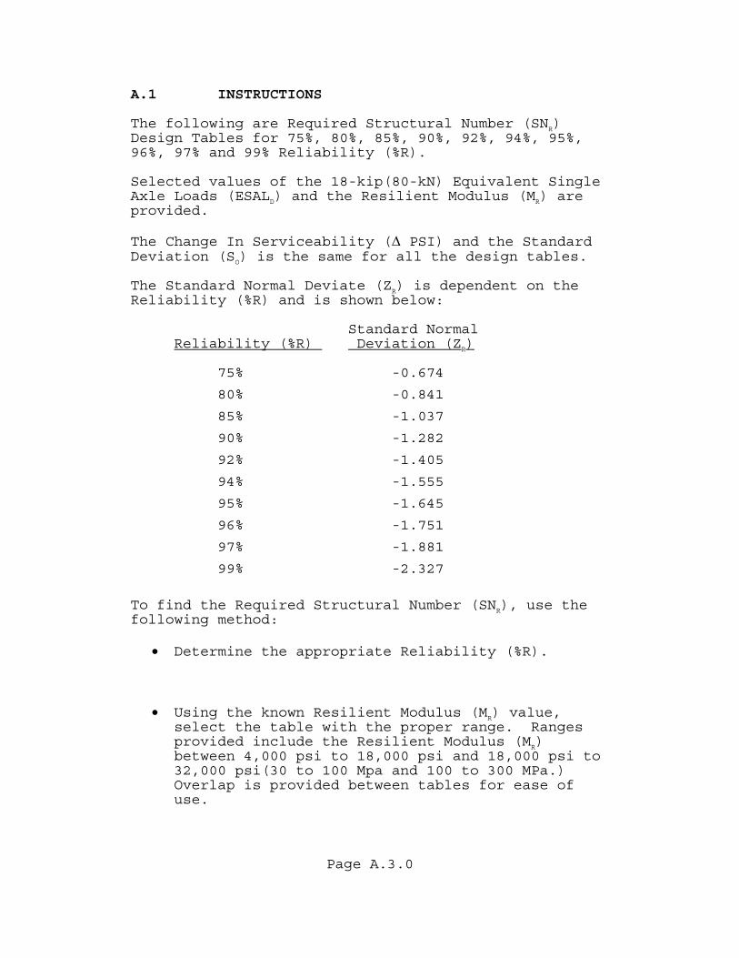
Page A.3.0
A.1 INSTRUCTIONS The following are Required Structural Number (SNR) Design Tables for 75%, 80%, 85%, 90%, 92%, 94%, 95%, 96%, 97% and 99% Reliability (%R). Selected values of the 18-kip(80-kN) Equivalent Single Axle Loads (ESALD) and the Resilient Modulus (MR) are provided. The Change In Serviceability (∆ PSI) and the Standard Deviation (SO) is the same for all the design tables. The Standard Normal Deviate (ZR) is dependent on the Reliability (%R) and is shown below:
Standard Normal Reliability (%R) Deviation (ZR)
75% -0.674
80% -0.841
85% -1.037
90% -1.282
92% -1.405
94% -1.555
95% -1.645
96% -1.751
97% -1.881
99% -2.327
To find the Required Structural Number (SNR), use the following method:
• Determine the appropriate Reliability (%R).
• Using the known Resilient Modulus (MR) value, select the table with the proper range. Ranges provided include the Resilient Modulus (MR) between 4,000 psi to 18,000 psi and 18,000 psi to 32,000 psi(30 to 100 Mpa and 100 to 300 MPa.) Overlap is provided between tables for ease of use.
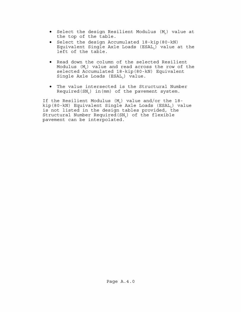
Page A.4.0
• Select the design Resilient Modulus (MR) value at the top of the table.
• Select the design Accumulated 18-kip(80-kN) Equivalent Single Axle Loads (ESALD) value at the left of the table.
• Read down the column of the selected Resilient
Modulus (MR) value and read across the row of the selected Accumulated 18-kip(80-kN) Equivalent Single Axle Loads (ESALD) value.
• The value intersected is the Structural Number
Required(SNR) in(mm) of the pavement system. If the Resilient Modulus (MR) value and/or the 18-kip(80-kN) Equivalent Single Axle Loads (ESALD) value is not listed in the design tables provided, the Structural Number Required(SNR) of the flexible pavement can be interpolated.
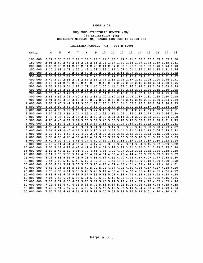
Page A.5.0
TABLE A.1A
REQUIRED STRUCTURAL NUMBER (SNR) 75% RELIABILITY (%R)
RESILIENT MODULUS (MR) RANGE 4000 PSI TO 18000 PSI
RESILIENT MODULUS (MR), (PSI x 1000) ESALD 4 5 6 7 8 9 10 11 12 13 14 15 16 17 18 100 000 2.72 2.50 2.33 2.19 2.08 1.99 1.91 1.83 1.77 1.71 1.66 1.62 1.57 1.53 1.50 150 000 2.91 2.67 2.49 2.35 2.23 2.13 2.04 1.97 1.90 1.84 1.79 1.74 1.69 1.65 1.61 200 000 3.05 2.80 2.61 2.46 2.34 2.23 2.14 2.07 2.00 1.93 1.88 1.83 1.78 1.74 1.70 250 000 3.17 2.91 2.71 2.55 2.43 2.32 2.23 2.14 2.07 2.01 1.95 1.90 1.85 1.81 1.76 300 000 3.27 3.00 2.79 2.63 2.50 2.39 2.29 2.21 2.14 2.07 2.01 1.96 1.91 1.86 1.82 350 000 3.35 3.08 2.87 2.70 2.57 2.45 2.35 2.27 2.19 2.13 2.07 2.01 1.96 1.91 1.87 400 000 3.42 3.14 2.93 2.76 2.62 2.51 2.41 2.32 2.24 2.17 2.11 2.06 2.00 1.96 1.91 450 000 3.49 3.21 2.99 2.82 2.68 2.56 2.46 2.37 2.29 2.22 2.15 2.10 2.04 2.00 1.95 500 000 3.55 3.26 3.04 2.87 2.72 2.60 2.50 2.41 2.33 2.26 2.19 2.13 2.08 2.03 1.99 600 000 3.66 3.36 3.14 2.95 2.81 2.68 2.58 2.48 2.40 2.33 2.26 2.20 2.15 2.10 2.05 700 000 3.75 3.45 3.22 3.03 2.88 2.75 2.64 2.55 2.46 2.39 2.32 2.26 2.20 2.15 2.10 800 000 3.83 3.52 3.29 3.10 2.94 2.81 2.70 2.60 2.52 2.44 2.37 2.31 2.25 2.20 2.15 900 000 3.91 3.59 3.35 3.16 3.00 2.87 2.75 2.66 2.57 2.49 2.42 2.36 2.30 2.24 2.19 1 000 000 3.97 3.65 3.41 3.22 3.06 2.92 2.80 2.70 2.61 2.53 2.46 2.40 2.34 2.28 2.23 1 500 000 4.23 3.90 3.64 3.44 3.27 3.12 3.00 2.89 2.80 2.71 2.63 2.57 2.50 2.44 2.39 2 000 000 4.42 4.08 3.82 3.60 3.43 3.27 3.15 3.03 2.93 2.84 2.76 2.69 2.62 2.56 2.51 2 500 000 4.57 4.23 3.96 3.74 3.55 3.40 3.26 3.15 3.04 2.95 2.87 2.79 2.72 2.66 2.60 3 000 000 4.70 4.35 4.07 3.85 3.66 3.50 3.36 3.24 3.14 3.04 2.96 2.88 2.81 2.74 2.68 3 500 000 4.80 4.45 4.17 3.94 3.75 3.59 3.45 3.33 3.22 3.12 3.03 2.95 2.88 2.81 2.75 4 000 000 4.90 4.54 4.26 4.03 3.83 3.67 3.53 3.40 3.29 3.19 3.10 3.02 2.94 2.88 2.81 4 500 000 4.98 4.62 4.33 4.10 3.91 3.74 3.59 3.47 3.35 3.25 3.16 3.08 3.00 2.93 2.87 5 000 000 5.06 4.69 4.40 4.17 3.97 3.80 3.66 3.53 3.41 3.31 3.22 3.13 3.06 2.99 2.92 6 000 000 5.19 4.82 4.53 4.29 4.09 3.91 3.76 3.63 3.52 3.41 3.31 3.23 3.15 3.08 3.01 7 000 000 5.30 4.93 4.63 4.39 4.19 4.01 3.86 3.72 3.60 3.50 3.40 3.31 3.23 3.16 3.09 8 000 000 5.40 5.02 4.72 4.48 4.27 4.10 3.94 3.81 3.68 3.57 3.48 3.39 3.30 3.23 3.16 9 000 000 5.49 5.11 4.81 4.56 4.35 4.17 4.02 3.88 3.75 3.64 3.54 3.45 3.37 3.29 3.22 10 000 000 5.57 5.18 4.88 4.63 4.42 4.24 4.08 3.94 3.82 3.71 3.60 3.51 3.43 3.35 3.28 15 000 000 5.88 5.48 5.17 4.91 4.70 4.51 4.35 4.20 4.07 3.95 3.85 3.75 3.66 3.58 3.50 20 000 000 6.11 5.70 5.38 5.12 4.90 4.71 4.54 4.39 4.26 4.14 4.03 3.93 3.83 3.75 3.67 25 000 000 6.29 5.88 5.55 5.28 5.06 4.86 4.69 4.54 4.40 4.28 4.17 4.07 3.97 3.88 3.80 30 000 000 6.44 6.02 5.69 5.42 5.19 4.99 4.82 4.67 4.53 4.40 4.29 4.18 4.09 4.00 3.92 35 000 000 6.57 6.14 5.81 5.53 5.30 5.10 4.93 4.77 4.63 4.51 4.39 4.28 4.19 4.10 4.01 40 000 000 6.68 6.25 5.91 5.63 5.40 5.20 5.02 4.87 4.72 4.60 4.48 4.37 4.27 4.18 4.10 45 000 000 6.78 6.35 6.01 5.73 5.49 5.29 5.11 4.95 4.81 4.68 4.56 4.45 4.35 4.26 4.17 50 000 000 6.88 6.43 6.09 5.81 5.57 5.36 5.18 5.02 4.88 4.75 4.63 4.52 4.42 4.33 4.24 60 000 000 7.04 6.59 6.24 5.95 5.71 5.50 5.32 5.16 5.01 4.88 4.76 4.65 4.55 4.45 4.36 70 000 000 7.17 6.72 6.36 6.07 5.83 5.62 5.43 5.27 5.12 4.99 4.87 4.75 4.65 4.55 4.46 80 000 000 7.29 6.83 6.47 6.18 5.93 5.72 5.53 5.37 5.22 5.08 4.96 4.85 4.74 4.65 4.55 90 000 000 7.40 6.94 6.57 6.28 6.03 5.81 5.62 5.45 5.30 5.17 5.04 4.93 4.82 4.73 4.64 100 000 000 7.50 7.03 6.66 6.36 6.11 5.89 5.70 5.53 5.38 5.25 5.12 5.01 4.90 4.80 4.71

Page A.6.0
TABLE A.1B
REQUIRED STRUCTURAL NUMBER (SNR) 75% RELIABILITY (%R)
RESILIENT MODULUS (MR) RANGE 18000 PSI TO 32000 PSI
RESILIENT MODULUS (MR), (PSI x 1000) ESALD 18 19 20 21 22 23 24 25 26 27 28 29 30 31 32 100 000 1.50 1.46 1.43 1.40 1.37 1.35 1.32 1.30 1.28 1.25 1.23 1.21 1.20 1.18 1.16 150 000 1.61 1.58 1.54 1.51 1.48 1.45 1.43 1.40 1.38 1.36 1.33 1.31 1.29 1.28 1.26 200 000 1.70 1.66 1.62 1.59 1.56 1.53 1.51 1.48 1.45 1.43 1.41 1.39 1.37 1.35 1.33 250 000 1.76 1.73 1.69 1.66 1.63 1.60 1.57 1.54 1.52 1.49 1.47 1.45 1.43 1.41 1.39 300 000 1.82 1.78 1.74 1.71 1.68 1.65 1.62 1.59 1.57 1.54 1.52 1.50 1.47 1.45 1.43 350 000 1.87 1.83 1.79 1.76 1.72 1.69 1.66 1.64 1.61 1.59 1.56 1.54 1.52 1.50 1.48 400 000 1.91 1.87 1.83 1.80 1.77 1.73 1.70 1.68 1.65 1.62 1.60 1.58 1.55 1.53 1.51 450 000 1.95 1.91 1.87 1.84 1.80 1.77 1.74 1.71 1.68 1.66 1.63 1.61 1.59 1.57 1.54 500 000 1.99 1.95 1.91 1.87 1.84 1.80 1.77 1.74 1.72 1.69 1.66 1.64 1.62 1.60 1.57 600 000 2.05 2.01 1.97 1.93 1.89 1.86 1.83 1.80 1.77 1.74 1.72 1.69 1.67 1.65 1.63 700 000 2.10 2.06 2.02 1.98 1.94 1.91 1.88 1.85 1.82 1.79 1.77 1.74 1.72 1.69 1.67 800 000 2.15 2.11 2.07 2.03 1.99 1.95 1.92 1.89 1.86 1.83 1.81 1.78 1.76 1.73 1.71 900 000 2.19 2.15 2.11 2.07 2.03 1.99 1.96 1.93 1.90 1.87 1.84 1.82 1.79 1.77 1.75 1 000 000 2.23 2.19 2.14 2.10 2.07 2.03 2.00 1.96 1.93 1.91 1.88 1.85 1.83 1.80 1.78 1 500 000 2.39 2.34 2.30 2.25 2.21 2.17 2.14 2.10 2.07 2.04 2.01 1.98 1.96 1.93 1.91 2 000 000 2.51 2.46 2.41 2.36 2.32 2.28 2.24 2.21 2.17 2.14 2.11 2.08 2.06 2.03 2.00 2 500 000 2.60 2.55 2.50 2.45 2.41 2.37 2.33 2.29 2.26 2.22 2.19 2.16 2.14 2.11 2.08 3 000 000 2.68 2.63 2.58 2.53 2.48 2.44 2.40 2.36 2.33 2.29 2.26 2.23 2.20 2.17 2.15 3 500 000 2.75 2.70 2.64 2.59 2.55 2.50 2.46 2.42 2.39 2.35 2.32 2.29 2.26 2.23 2.20 4 000 000 2.81 2.76 2.70 2.65 2.60 2.56 2.52 2.48 2.44 2.41 2.37 2.34 2.31 2.28 2.25 4 500 000 2.87 2.81 2.76 2.70 2.66 2.61 2.57 2.53 2.49 2.45 2.42 2.39 2.36 2.33 2.30 5 000 000 2.92 2.86 2.80 2.75 2.70 2.66 2.61 2.57 2.53 2.50 2.46 2.43 2.40 2.37 2.34 6 000 000 3.01 2.95 2.89 2.84 2.79 2.74 2.69 2.65 2.61 2.57 2.54 2.50 2.47 2.44 2.41 7 000 000 3.09 3.02 2.97 2.91 2.86 2.81 2.76 2.72 2.68 2.64 2.60 2.57 2.54 2.50 2.47 8 000 000 3.16 3.09 3.03 2.98 2.92 2.87 2.83 2.78 2.74 2.70 2.66 2.63 2.59 2.56 2.53 9 000 000 3.22 3.15 3.09 3.03 2.98 2.93 2.88 2.84 2.79 2.75 2.72 2.68 2.64 2.61 2.58 10 000 000 3.28 3.21 3.15 3.09 3.03 2.98 2.93 2.89 2.84 2.80 2.76 2.73 2.69 2.66 2.63 15 000 000 3.50 3.43 3.36 3.30 3.24 3.19 3.14 3.09 3.04 3.00 2.96 2.92 2.88 2.84 2.81 20 000 000 3.67 3.60 3.53 3.46 3.40 3.34 3.29 3.24 3.19 3.14 3.10 3.06 3.02 2.98 2.95 25 000 000 3.80 3.73 3.66 3.59 3.53 3.47 3.41 3.36 3.31 3.26 3.22 3.17 3.13 3.09 3.06 30 000 000 3.92 3.84 3.77 3.70 3.63 3.57 3.52 3.46 3.41 3.36 3.32 3.27 3.23 3.19 3.15 35 000 000 4.01 3.93 3.86 3.79 3.73 3.66 3.61 3.55 3.50 3.45 3.40 3.36 3.31 3.27 3.23 40 000 000 4.10 4.02 3.94 3.87 3.81 3.74 3.68 3.63 3.58 3.52 3.48 3.43 3.39 3.34 3.30 45 000 000 4.17 4.09 4.02 3.95 3.88 3.82 3.76 3.70 3.64 3.59 3.54 3.50 3.45 3.41 3.37 50 000 000 4.24 4.16 4.08 4.01 3.94 3.88 3.82 3.76 3.71 3.65 3.60 3.56 3.51 3.47 3.43 60 000 000 4.36 4.28 4.20 4.13 4.06 3.99 3.93 3.87 3.82 3.76 3.71 3.66 3.62 3.57 3.53 70 000 000 4.46 4.38 4.30 4.23 4.16 4.09 4.03 3.97 3.91 3.86 3.81 3.76 3.71 3.66 3.62 80 000 000 4.55 4.47 4.39 4.32 4.24 4.18 4.11 4.05 4.00 3.94 3.89 3.84 3.79 3.74 3.70 90 000 000 4.64 4.55 4.47 4.39 4.32 4.25 4.19 4.13 4.07 4.01 3.96 3.91 3.86 3.82 3.77 100 000 000 4.71 4.62 4.54 4.46 4.39 4.32 4.26 4.20 4.14 4.08 4.03 3.98 3.93 3.88 3.83
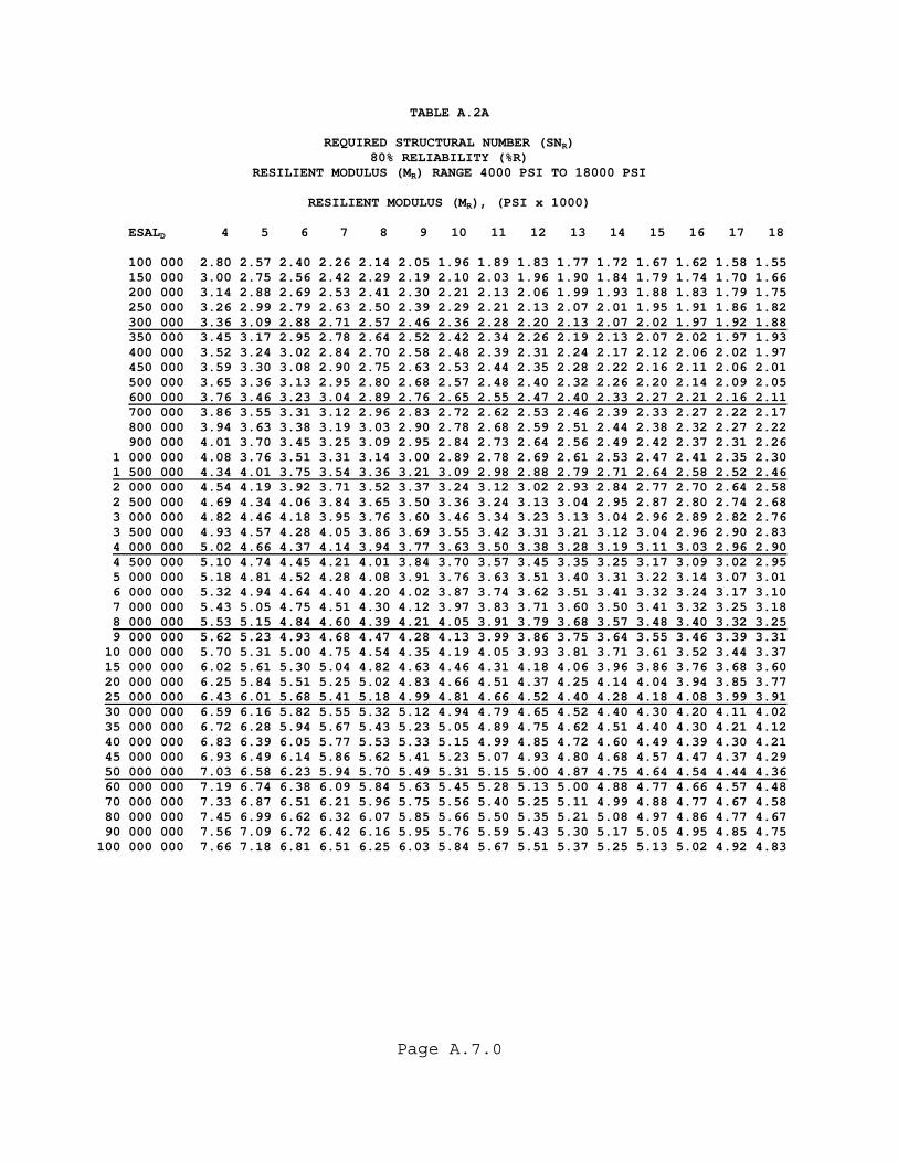
Page A.7.0
TABLE A.2A
REQUIRED STRUCTURAL NUMBER (SNR) 80% RELIABILITY (%R)
RESILIENT MODULUS (MR) RANGE 4000 PSI TO 18000 PSI
RESILIENT MODULUS (MR), (PSI x 1000) ESALD 4 5 6 7 8 9 10 11 12 13 14 15 16 17 18 100 000 2.80 2.57 2.40 2.26 2.14 2.05 1.96 1.89 1.83 1.77 1.72 1.67 1.62 1.58 1.55 150 000 3.00 2.75 2.56 2.42 2.29 2.19 2.10 2.03 1.96 1.90 1.84 1.79 1.74 1.70 1.66 200 000 3.14 2.88 2.69 2.53 2.41 2.30 2.21 2.13 2.06 1.99 1.93 1.88 1.83 1.79 1.75 250 000 3.26 2.99 2.79 2.63 2.50 2.39 2.29 2.21 2.13 2.07 2.01 1.95 1.91 1.86 1.82 300 000 3.36 3.09 2.88 2.71 2.57 2.46 2.36 2.28 2.20 2.13 2.07 2.02 1.97 1.92 1.88 350 000 3.45 3.17 2.95 2.78 2.64 2.52 2.42 2.34 2.26 2.19 2.13 2.07 2.02 1.97 1.93 400 000 3.52 3.24 3.02 2.84 2.70 2.58 2.48 2.39 2.31 2.24 2.17 2.12 2.06 2.02 1.97 450 000 3.59 3.30 3.08 2.90 2.75 2.63 2.53 2.44 2.35 2.28 2.22 2.16 2.11 2.06 2.01 500 000 3.65 3.36 3.13 2.95 2.80 2.68 2.57 2.48 2.40 2.32 2.26 2.20 2.14 2.09 2.05 600 000 3.76 3.46 3.23 3.04 2.89 2.76 2.65 2.55 2.47 2.40 2.33 2.27 2.21 2.16 2.11 700 000 3.86 3.55 3.31 3.12 2.96 2.83 2.72 2.62 2.53 2.46 2.39 2.33 2.27 2.22 2.17 800 000 3.94 3.63 3.38 3.19 3.03 2.90 2.78 2.68 2.59 2.51 2.44 2.38 2.32 2.27 2.22 900 000 4.01 3.70 3.45 3.25 3.09 2.95 2.84 2.73 2.64 2.56 2.49 2.42 2.37 2.31 2.26 1 000 000 4.08 3.76 3.51 3.31 3.14 3.00 2.89 2.78 2.69 2.61 2.53 2.47 2.41 2.35 2.30 1 500 000 4.34 4.01 3.75 3.54 3.36 3.21 3.09 2.98 2.88 2.79 2.71 2.64 2.58 2.52 2.46 2 000 000 4.54 4.19 3.92 3.71 3.52 3.37 3.24 3.12 3.02 2.93 2.84 2.77 2.70 2.64 2.58 2 500 000 4.69 4.34 4.06 3.84 3.65 3.50 3.36 3.24 3.13 3.04 2.95 2.87 2.80 2.74 2.68 3 000 000 4.82 4.46 4.18 3.95 3.76 3.60 3.46 3.34 3.23 3.13 3.04 2.96 2.89 2.82 2.76 3 500 000 4.93 4.57 4.28 4.05 3.86 3.69 3.55 3.42 3.31 3.21 3.12 3.04 2.96 2.90 2.83 4 000 000 5.02 4.66 4.37 4.14 3.94 3.77 3.63 3.50 3.38 3.28 3.19 3.11 3.03 2.96 2.90 4 500 000 5.10 4.74 4.45 4.21 4.01 3.84 3.70 3.57 3.45 3.35 3.25 3.17 3.09 3.02 2.95 5 000 000 5.18 4.81 4.52 4.28 4.08 3.91 3.76 3.63 3.51 3.40 3.31 3.22 3.14 3.07 3.01 6 000 000 5.32 4.94 4.64 4.40 4.20 4.02 3.87 3.74 3.62 3.51 3.41 3.32 3.24 3.17 3.10 7 000 000 5.43 5.05 4.75 4.51 4.30 4.12 3.97 3.83 3.71 3.60 3.50 3.41 3.32 3.25 3.18 8 000 000 5.53 5.15 4.84 4.60 4.39 4.21 4.05 3.91 3.79 3.68 3.57 3.48 3.40 3.32 3.25 9 000 000 5.62 5.23 4.93 4.68 4.47 4.28 4.13 3.99 3.86 3.75 3.64 3.55 3.46 3.39 3.31 10 000 000 5.70 5.31 5.00 4.75 4.54 4.35 4.19 4.05 3.93 3.81 3.71 3.61 3.52 3.44 3.37 15 000 000 6.02 5.61 5.30 5.04 4.82 4.63 4.46 4.31 4.18 4.06 3.96 3.86 3.76 3.68 3.60 20 000 000 6.25 5.84 5.51 5.25 5.02 4.83 4.66 4.51 4.37 4.25 4.14 4.04 3.94 3.85 3.77 25 000 000 6.43 6.01 5.68 5.41 5.18 4.99 4.81 4.66 4.52 4.40 4.28 4.18 4.08 3.99 3.91 30 000 000 6.59 6.16 5.82 5.55 5.32 5.12 4.94 4.79 4.65 4.52 4.40 4.30 4.20 4.11 4.02 35 000 000 6.72 6.28 5.94 5.67 5.43 5.23 5.05 4.89 4.75 4.62 4.51 4.40 4.30 4.21 4.12 40 000 000 6.83 6.39 6.05 5.77 5.53 5.33 5.15 4.99 4.85 4.72 4.60 4.49 4.39 4.30 4.21 45 000 000 6.93 6.49 6.14 5.86 5.62 5.41 5.23 5.07 4.93 4.80 4.68 4.57 4.47 4.37 4.29 50 000 000 7.03 6.58 6.23 5.94 5.70 5.49 5.31 5.15 5.00 4.87 4.75 4.64 4.54 4.44 4.36 60 000 000 7.19 6.74 6.38 6.09 5.84 5.63 5.45 5.28 5.13 5.00 4.88 4.77 4.66 4.57 4.48 70 000 000 7.33 6.87 6.51 6.21 5.96 5.75 5.56 5.40 5.25 5.11 4.99 4.88 4.77 4.67 4.58 80 000 000 7.45 6.99 6.62 6.32 6.07 5.85 5.66 5.50 5.35 5.21 5.08 4.97 4.86 4.77 4.67 90 000 000 7.56 7.09 6.72 6.42 6.16 5.95 5.76 5.59 5.43 5.30 5.17 5.05 4.95 4.85 4.75 100 000 000 7.66 7.18 6.81 6.51 6.25 6.03 5.84 5.67 5.51 5.37 5.25 5.13 5.02 4.92 4.83

Page A.8.0
TABLE A.2B
REQUIRED STRUCTURAL NUMBER (SNR) 80% RELIABILITY (%R)
RESILIENT MODULUS (MR) RANGE 18000 PSI TO 32000 PSI
RESILIENT MODULUS (MR), (PSI x 1000) ESALD 18 19 20 21 22 23 24 25 26 27 28 29 30 31 32 100 000 1.55 1.51 1.48 1.45 1.42 1.39 1.37 1.34 1.32 1.30 1.28 1.26 1.24 1.22 1.20 150 000 1.66 1.63 1.59 1.56 1.53 1.50 1.47 1.45 1.42 1.40 1.38 1.36 1.34 1.32 1.30 200 000 1.75 1.71 1.68 1.64 1.61 1.58 1.55 1.53 1.50 1.48 1.46 1.43 1.41 1.39 1.37 250 000 1.82 1.78 1.74 1.71 1.68 1.65 1.62 1.59 1.56 1.54 1.52 1.49 1.47 1.45 1.43 300 000 1.88 1.84 1.80 1.76 1.73 1.70 1.67 1.64 1.62 1.59 1.57 1.54 1.52 1.50 1.48 350 000 1.93 1.89 1.85 1.81 1.78 1.75 1.72 1.69 1.66 1.64 1.61 1.59 1.57 1.54 1.52 400 000 1.97 1.93 1.89 1.85 1.82 1.79 1.76 1.73 1.70 1.67 1.65 1.63 1.60 1.58 1.56 450 000 2.01 1.97 1.93 1.89 1.86 1.82 1.79 1.76 1.74 1.71 1.68 1.66 1.64 1.62 1.59 500 000 2.05 2.00 1.96 1.93 1.89 1.86 1.83 1.80 1.77 1.74 1.72 1.69 1.67 1.65 1.62 600 000 2.11 2.07 2.03 1.99 1.95 1.92 1.88 1.85 1.82 1.80 1.77 1.75 1.72 1.70 1.68 700 000 2.17 2.12 2.08 2.04 2.00 1.97 1.93 1.90 1.87 1.85 1.82 1.79 1.77 1.75 1.72 800 000 2.22 2.17 2.13 2.09 2.05 2.01 1.98 1.95 1.92 1.89 1.86 1.84 1.81 1.79 1.76 900 000 2.26 2.21 2.17 2.13 2.09 2.05 2.02 1.99 1.96 1.93 1.90 1.87 1.85 1.82 1.80 1 000 000 2.30 2.25 2.21 2.17 2.13 2.09 2.06 2.02 1.99 1.96 1.93 1.91 1.88 1.86 1.83 1 500 000 2.46 2.41 2.36 2.32 2.28 2.24 2.20 2.17 2.13 2.10 2.07 2.04 2.02 1.99 1.97 2 000 000 2.58 2.53 2.48 2.43 2.39 2.35 2.31 2.27 2.24 2.21 2.18 2.15 2.12 2.09 2.06 2 500 000 2.68 2.62 2.57 2.52 2.48 2.44 2.40 2.36 2.32 2.29 2.26 2.23 2.20 2.17 2.14 3 000 000 2.76 2.70 2.65 2.60 2.56 2.51 2.47 2.43 2.40 2.36 2.33 2.30 2.27 2.24 2.21 3 500 000 2.83 2.77 2.72 2.67 2.62 2.58 2.54 2.50 2.46 2.42 2.39 2.36 2.33 2.30 2.27 4 000 000 2.90 2.84 2.78 2.73 2.68 2.64 2.59 2.55 2.51 2.48 2.44 2.41 2.38 2.35 2.32 4 500 000 2.95 2.89 2.84 2.78 2.73 2.69 2.64 2.60 2.56 2.53 2.49 2.46 2.43 2.39 2.37 5 000 000 3.01 2.94 2.89 2.83 2.78 2.73 2.69 2.65 2.61 2.57 2.53 2.50 2.47 2.44 2.41 6 000 000 3.10 3.03 2.97 2.92 2.87 2.82 2.77 2.73 2.69 2.65 2.61 2.58 2.54 2.51 2.48 7 000 000 3.18 3.11 3.05 2.99 2.94 2.89 2.84 2.80 2.76 2.72 2.68 2.64 2.61 2.58 2.55 8 000 000 3.25 3.18 3.12 3.06 3.01 2.96 2.91 2.86 2.82 2.78 2.74 2.70 2.67 2.64 2.60 9 000 000 3.31 3.24 3.18 3.12 3.07 3.02 2.97 2.92 2.88 2.83 2.80 2.76 2.72 2.69 2.65 10 000 000 3.37 3.30 3.24 3.18 3.12 3.07 3.02 2.97 2.93 2.88 2.84 2.81 2.77 2.73 2.70 15 000 000 3.60 3.53 3.46 3.40 3.34 3.28 3.23 3.18 3.13 3.09 3.04 3.00 2.96 2.93 2.89 20 000 000 3.77 3.70 3.63 3.56 3.50 3.44 3.38 3.33 3.28 3.24 3.19 3.15 3.11 3.07 3.03 25 000 000 3.91 3.83 3.76 3.69 3.63 3.57 3.51 3.46 3.41 3.36 3.31 3.27 3.22 3.18 3.15 30 000 000 4.02 3.95 3.87 3.80 3.74 3.67 3.62 3.56 3.51 3.46 3.41 3.37 3.32 3.28 3.24 35 000 000 4.12 4.04 3.97 3.90 3.83 3.77 3.71 3.65 3.60 3.55 3.50 3.45 3.41 3.37 3.33 40 000 000 4.21 4.13 4.05 3.98 3.91 3.85 3.79 3.73 3.68 3.63 3.58 3.53 3.48 3.44 3.40 45 000 000 4.29 4.20 4.13 4.05 3.99 3.92 3.86 3.80 3.75 3.70 3.64 3.60 3.55 3.51 3.47 50 000 000 4.36 4.27 4.19 4.12 4.05 3.99 3.93 3.87 3.81 3.76 3.71 3.66 3.61 3.57 3.53 60 000 000 4.48 4.39 4.31 4.24 4.17 4.10 4.04 3.98 3.92 3.87 3.82 3.77 3.72 3.68 3.63 70 000 000 4.58 4.50 4.42 4.34 4.27 4.20 4.14 4.08 4.02 3.97 3.91 3.86 3.81 3.77 3.72 80 000 000 4.67 4.59 4.51 4.43 4.36 4.29 4.23 4.16 4.11 4.05 4.00 3.95 3.90 3.85 3.80 90 000 000 4.75 4.67 4.59 4.51 4.44 4.37 4.30 4.24 4.18 4.12 4.07 4.02 3.97 3.92 3.88 100 000 000 4.83 4.74 4.66 4.58 4.51 4.44 4.37 4.31 4.25 4.19 4.14 4.09 4.04 3.99 3.94
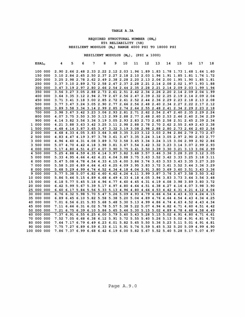
Page A.9.0
TABLE A.3A
REQUIRED STRUCTURAL NUMBER (SNR) 85% RELIABILITY (%R)
RESILIENT MODULUS (MR) RANGE 4000 PSI TO 18000 PSI
RESILIENT MODULUS (MR), (PSI x 1000) ESALD 4 5 6 7 8 9 10 11 12 13 14 15 16 17 18 100 000 2.90 2.66 2.48 2.33 2.22 2.12 2.03 1.96 1.89 1.83 1.78 1.73 1.68 1.64 1.60 150 000 3.10 2.84 2.65 2.50 2.37 2.27 2.18 2.10 2.03 1.96 1.91 1.85 1.81 1.76 1.72 200 000 3.25 2.98 2.78 2.62 2.49 2.38 2.28 2.20 2.13 2.06 2.00 1.95 1.90 1.85 1.81 250 000 3.37 3.10 2.89 2.72 2.58 2.47 2.37 2.28 2.21 2.14 2.08 2.02 1.97 1.93 1.88 300 000 3.47 3.19 2.97 2.80 2.66 2.54 2.44 2.35 2.28 2.21 2.14 2.09 2.03 1.99 1.94 350 000 3.56 3.27 3.05 2.88 2.73 2.61 2.51 2.42 2.34 2.26 2.20 2.14 2.09 2.04 1.99 400 000 3.64 3.35 3.12 2.94 2.79 2.67 2.56 2.47 2.39 2.32 2.25 2.19 2.14 2.09 2.04 450 000 3.71 3.41 3.18 3.00 2.85 2.72 2.61 2.52 2.44 2.36 2.29 2.23 2.18 2.13 2.08 500 000 3.77 3.47 3.24 3.05 2.90 2.77 2.66 2.56 2.48 2.40 2.34 2.27 2.22 2.17 2.12 600 000 3.89 3.58 3.34 3.14 2.99 2.85 2.74 2.64 2.55 2.48 2.41 2.34 2.29 2.23 2.18 700 000 3.98 3.67 3.42 3.23 3.06 2.93 2.81 2.71 2.62 2.54 2.47 2.40 2.35 2.29 2.24 800 000 4.07 3.75 3.50 3.30 3.13 2.99 2.88 2.77 2.68 2.60 2.53 2.46 2.40 2.34 2.29 900 000 4.14 3.82 3.56 3.36 3.19 3.05 2.93 2.83 2.73 2.65 2.58 2.51 2.45 2.39 2.34 1 000 000 4.21 3.88 3.63 3.42 3.25 3.11 2.98 2.88 2.78 2.70 2.62 2.55 2.49 2.43 2.38 1 500 000 4.48 4.14 3.87 3.65 3.47 3.32 3.19 3.08 2.98 2.88 2.80 2.73 2.66 2.60 2.54 2 000 000 4.68 4.33 4.05 3.83 3.64 3.48 3.35 3.23 3.12 3.03 2.94 2.86 2.79 2.73 2.67 2 500 000 4.83 4.47 4.19 3.97 3.78 3.61 3.47 3.35 3.24 3.14 3.05 2.97 2.90 2.83 2.77 3 000 000 4.96 4.60 4.31 4.08 3.89 3.72 3.58 3.45 3.34 3.24 3.15 3.06 2.99 2.92 2.86 3 500 000 5.07 4.70 4.42 4.18 3.98 3.81 3.67 3.54 3.42 3.32 3.23 3.14 3.07 2.99 2.93 4 000 000 5.17 4.80 4.51 4.27 4.07 3.90 3.75 3.61 3.50 3.39 3.30 3.21 3.13 3.06 2.99 4 500 000 5.25 4.88 4.59 4.35 4.14 3.97 3.82 3.68 3.57 3.46 3.36 3.28 3.20 3.12 3.05 5 000 000 5.33 4.95 4.66 4.42 4.21 4.04 3.88 3.75 3.63 3.52 3.42 3.33 3.25 3.18 3.11 6 000 000 5.47 5.08 4.78 4.54 4.33 4.15 4.00 3.86 3.74 3.63 3.53 3.43 3.35 3.27 3.20 7 000 000 5.58 5.20 4.89 4.64 4.43 4.25 4.09 3.95 3.83 3.72 3.61 3.52 3.44 3.36 3.29 8 000 000 5.68 5.29 4.99 4.74 4.52 4.34 4.18 4.04 3.91 3.80 3.69 3.60 3.51 3.43 3.36 9 000 000 5.77 5.38 5.07 4.82 4.60 4.42 4.26 4.11 3.99 3.87 3.76 3.67 3.58 3.50 3.42 10 000 000 5.86 5.46 5.15 4.89 4.68 4.49 4.33 4.18 4.05 3.94 3.83 3.73 3.64 3.56 3.48 15 000 000 6.18 5.77 5.45 5.18 4.96 4.77 4.60 4.45 4.31 4.19 4.08 3.98 3.89 3.80 3.72 20 000 000 6.42 5.99 5.67 5.39 5.17 4.97 4.80 4.64 4.51 4.38 4.27 4.16 4.07 3.98 3.90 25 000 000 6.60 6.17 5.84 5.56 5.33 5.13 4.96 4.80 4.66 4.53 4.42 4.31 4.21 4.12 4.04 30 000 000 6.76 6.32 5.98 5.70 5.47 5.26 5.09 4.93 4.79 4.66 4.54 4.43 4.33 4.24 4.15 35 000 000 6.89 6.45 6.10 5.82 5.58 5.38 5.20 5.04 4.89 4.76 4.64 4.54 4.43 4.34 4.25 40 000 000 7.01 6.56 6.21 5.93 5.68 5.48 5.30 5.13 4.99 4.86 4.74 4.63 4.52 4.43 4.34 45 000 000 7.11 6.66 6.31 6.02 5.78 5.57 5.38 5.22 5.07 4.94 4.82 4.71 4.60 4.51 4.42 50 000 000 7.21 6.75 6.39 6.10 5.86 5.65 5.46 5.30 5.15 5.02 4.89 4.78 4.68 4.58 4.49 60 000 000 7.37 6.91 6.55 6.25 6.00 5.79 5.60 5.43 5.28 5.15 5.02 4.91 4.80 4.71 4.61 70 000 000 7.52 7.05 6.68 6.38 6.12 5.91 5.72 5.55 5.40 5.26 5.13 5.02 4.91 4.81 4.72 80 000 000 7.64 7.17 6.79 6.49 6.23 6.01 5.82 5.65 5.50 5.36 5.23 5.11 5.01 4.91 4.81 90 000 000 7.75 7.27 6.89 6.59 6.33 6.11 5.91 5.74 5.59 5.45 5.32 5.20 5.09 4.99 4.90 100 000 000 7.86 7.37 6.99 6.68 6.42 6.19 6.00 5.82 5.67 5.52 5.40 5.28 5.17 5.07 4.97
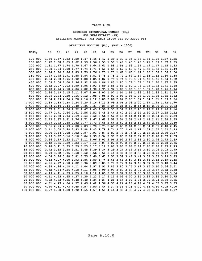
Page A.10.0
TABLE A.3B
REQUIRED STRUCTURAL NUMBER (SNR) 85% RELIABILITY (%R)
RESILIENT MODULUS (MR) RANGE 18000 PSI TO 32000 PSI
RESILIENT MODULUS (MR), (PSI x 1000) ESALD 18 19 20 21 22 23 24 25 26 27 28 29 30 31 32 100 000 1.60 1.57 1.53 1.50 1.47 1.45 1.42 1.39 1.37 1.35 1.33 1.31 1.29 1.27 1.25 150 000 1.72 1.68 1.65 1.62 1.59 1.56 1.53 1.50 1.48 1.45 1.43 1.41 1.39 1.37 1.35 200 000 1.81 1.77 1.74 1.70 1.67 1.64 1.61 1.58 1.56 1.53 1.51 1.49 1.47 1.45 1.43 250 000 1.88 1.84 1.80 1.77 1.74 1.71 1.68 1.65 1.62 1.60 1.57 1.55 1.53 1.51 1.49 300 000 1.94 1.90 1.86 1.83 1.79 1.76 1.73 1.70 1.67 1.65 1.62 1.60 1.58 1.56 1.54 350 000 1.99 1.95 1.91 1.88 1.84 1.81 1.78 1.75 1.72 1.69 1.67 1.65 1.62 1.60 1.58 400 000 2.04 2.00 1.96 1.92 1.88 1.85 1.82 1.79 1.76 1.73 1.71 1.68 1.66 1.64 1.62 450 000 2.08 2.04 2.00 1.96 1.92 1.89 1.86 1.83 1.80 1.77 1.74 1.72 1.70 1.67 1.65 500 000 2.12 2.07 2.03 1.99 1.96 1.92 1.89 1.86 1.83 1.80 1.78 1.75 1.73 1.71 1.68 600 000 2.18 2.14 2.10 2.06 2.02 1.98 1.95 1.92 1.89 1.86 1.83 1.81 1.78 1.76 1.74 700 000 2.24 2.19 2.15 2.11 2.07 2.04 2.00 1.97 1.94 1.91 1.88 1.86 1.83 1.81 1.79 800 000 2.29 2.24 2.20 2.16 2.12 2.08 2.05 2.02 1.98 1.96 1.93 1.90 1.88 1.85 1.83 900 000 2.34 2.29 2.24 2.20 2.16 2.12 2.09 2.06 2.02 2.00 1.97 1.94 1.91 1.89 1.86 1 000 000 2.38 2.33 2.28 2.24 2.20 2.16 2.13 2.09 2.06 2.03 2.00 1.97 1.95 1.92 1.90 1 500 000 2.54 2.49 2.44 2.40 2.35 2.31 2.28 2.24 2.21 2.17 2.14 2.12 2.09 2.06 2.03 2 000 000 2.67 2.61 2.56 2.52 2.47 2.43 2.39 2.35 2.32 2.28 2.25 2.22 2.19 2.16 2.14 2 500 000 2.77 2.71 2.66 2.61 2.56 2.52 2.48 2.44 2.40 2.37 2.34 2.30 2.27 2.25 2.22 3 000 000 2.86 2.80 2.74 2.69 2.64 2.60 2.56 2.52 2.48 2.44 2.41 2.38 2.34 2.31 2.29 3 500 000 2.93 2.87 2.81 2.76 2.71 2.67 2.62 2.58 2.54 2.51 2.47 2.44 2.41 2.38 2.35 4 000 000 2.99 2.93 2.88 2.82 2.77 2.73 2.68 2.64 2.60 2.56 2.53 2.49 2.46 2.43 2.40 4 500 000 3.05 2.99 2.93 2.88 2.83 2.78 2.73 2.69 2.65 2.61 2.58 2.54 2.51 2.48 2.45 5 000 000 3.11 3.04 2.98 2.93 2.88 2.83 2.78 2.74 2.70 2.66 2.62 2.59 2.55 2.52 2.49 6 000 000 3.20 3.14 3.08 3.02 2.97 2.91 2.87 2.82 2.78 2.74 2.70 2.67 2.63 2.60 2.57 7 000 000 3.29 3.22 3.16 3.10 3.04 2.99 2.94 2.90 2.85 2.81 2.77 2.73 2.70 2.67 2.63 8 000 000 3.36 3.29 3.23 3.17 3.11 3.06 3.01 2.96 2.92 2.87 2.83 2.80 2.76 2.73 2.69 9 000 000 3.42 3.35 3.29 3.23 3.17 3.12 3.07 3.02 2.97 2.93 2.89 2.85 2.81 2.78 2.75 10 000 000 3.48 3.41 3.35 3.29 3.23 3.17 3.12 3.07 3.03 2.98 2.94 2.90 2.86 2.83 2.79 15 000 000 3.72 3.65 3.58 3.51 3.45 3.39 3.34 3.29 3.24 3.19 3.15 3.10 3.06 3.03 2.99 20 000 000 3.90 3.82 3.75 3.68 3.62 3.56 3.50 3.44 3.39 3.35 3.30 3.25 3.21 3.17 3.13 25 000 000 4.04 3.96 3.88 3.81 3.75 3.69 3.63 3.57 3.52 3.47 3.42 3.38 3.33 3.29 3.25 30 000 000 4.15 4.07 4.00 3.93 3.86 3.80 3.74 3.68 3.63 3.57 3.53 3.48 3.43 3.39 3.35 35 000 000 4.25 4.17 4.10 4.02 3.96 3.89 3.83 3.77 3.72 3.67 3.62 3.57 3.52 3.48 3.44 40 000 000 4.34 4.26 4.18 4.11 4.04 3.97 3.91 3.85 3.80 3.75 3.69 3.65 3.60 3.56 3.51 45 000 000 4.42 4.34 4.26 4.18 4.11 4.05 3.99 3.93 3.87 3.82 3.77 3.72 3.67 3.62 3.58 50 000 000 4.49 4.41 4.33 4.25 4.18 4.12 4.05 3.99 3.94 3.88 3.83 3.78 3.73 3.69 3.64 60 000 000 4.61 4.53 4.45 4.37 4.30 4.23 4.17 4.11 4.05 4.00 3.94 3.89 3.84 3.80 3.75 70 000 000 4.72 4.63 4.55 4.48 4.40 4.34 4.27 4.21 4.15 4.09 4.04 3.99 3.94 3.89 3.85 80 000 000 4.81 4.73 4.64 4.57 4.49 4.42 4.36 4.30 4.24 4.18 4.12 4.07 4.02 3.97 3.93 90 000 000 4.90 4.81 4.73 4.65 4.57 4.50 4.44 4.37 4.31 4.26 4.20 4.15 4.10 4.05 4.00 100 000 000 4.97 4.88 4.80 4.72 4.65 4.57 4.51 4.44 4.38 4.33 4.27 4.22 4.17 4.12 4.07
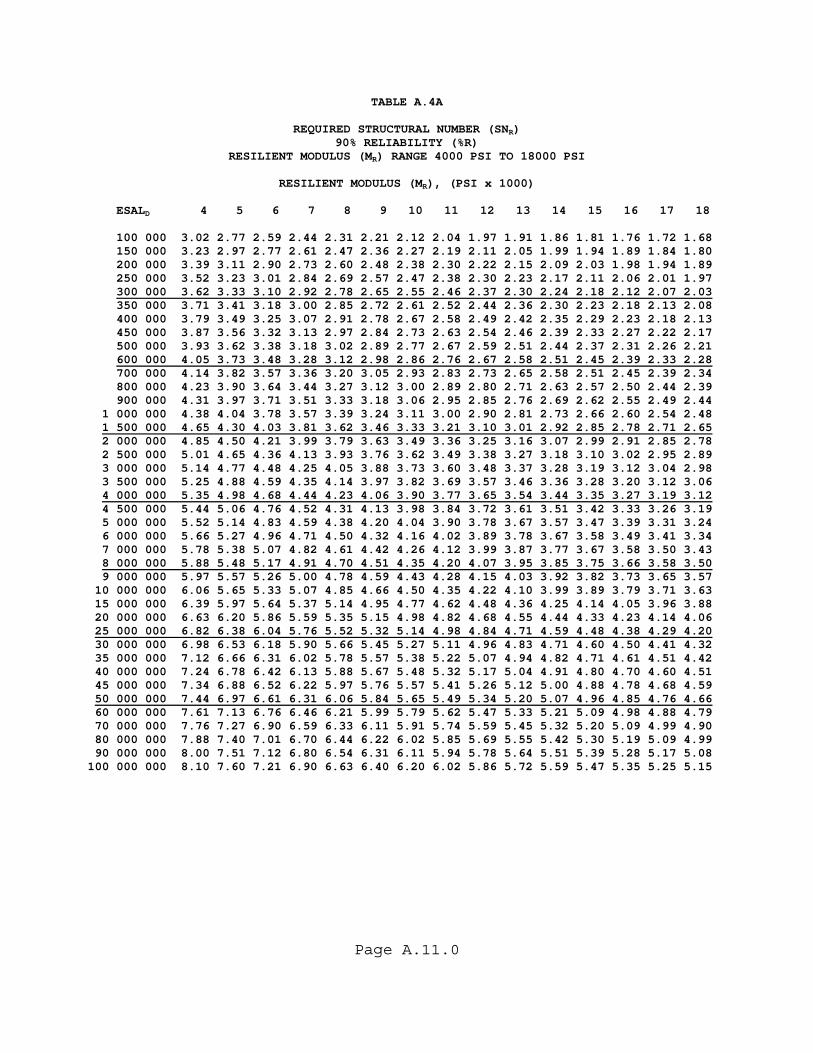
Page A.11.0
TABLE A.4A
REQUIRED STRUCTURAL NUMBER (SNR) 90% RELIABILITY (%R)
RESILIENT MODULUS (MR) RANGE 4000 PSI TO 18000 PSI
RESILIENT MODULUS (MR), (PSI x 1000) ESALD 4 5 6 7 8 9 10 11 12 13 14 15 16 17 18 100 000 3.02 2.77 2.59 2.44 2.31 2.21 2.12 2.04 1.97 1.91 1.86 1.81 1.76 1.72 1.68 150 000 3.23 2.97 2.77 2.61 2.47 2.36 2.27 2.19 2.11 2.05 1.99 1.94 1.89 1.84 1.80 200 000 3.39 3.11 2.90 2.73 2.60 2.48 2.38 2.30 2.22 2.15 2.09 2.03 1.98 1.94 1.89 250 000 3.52 3.23 3.01 2.84 2.69 2.57 2.47 2.38 2.30 2.23 2.17 2.11 2.06 2.01 1.97 300 000 3.62 3.33 3.10 2.92 2.78 2.65 2.55 2.46 2.37 2.30 2.24 2.18 2.12 2.07 2.03 350 000 3.71 3.41 3.18 3.00 2.85 2.72 2.61 2.52 2.44 2.36 2.30 2.23 2.18 2.13 2.08 400 000 3.79 3.49 3.25 3.07 2.91 2.78 2.67 2.58 2.49 2.42 2.35 2.29 2.23 2.18 2.13 450 000 3.87 3.56 3.32 3.13 2.97 2.84 2.73 2.63 2.54 2.46 2.39 2.33 2.27 2.22 2.17 500 000 3.93 3.62 3.38 3.18 3.02 2.89 2.77 2.67 2.59 2.51 2.44 2.37 2.31 2.26 2.21 600 000 4.05 3.73 3.48 3.28 3.12 2.98 2.86 2.76 2.67 2.58 2.51 2.45 2.39 2.33 2.28 700 000 4.14 3.82 3.57 3.36 3.20 3.05 2.93 2.83 2.73 2.65 2.58 2.51 2.45 2.39 2.34 800 000 4.23 3.90 3.64 3.44 3.27 3.12 3.00 2.89 2.80 2.71 2.63 2.57 2.50 2.44 2.39 900 000 4.31 3.97 3.71 3.51 3.33 3.18 3.06 2.95 2.85 2.76 2.69 2.62 2.55 2.49 2.44 1 000 000 4.38 4.04 3.78 3.57 3.39 3.24 3.11 3.00 2.90 2.81 2.73 2.66 2.60 2.54 2.48 1 500 000 4.65 4.30 4.03 3.81 3.62 3.46 3.33 3.21 3.10 3.01 2.92 2.85 2.78 2.71 2.65 2 000 000 4.85 4.50 4.21 3.99 3.79 3.63 3.49 3.36 3.25 3.16 3.07 2.99 2.91 2.85 2.78 2 500 000 5.01 4.65 4.36 4.13 3.93 3.76 3.62 3.49 3.38 3.27 3.18 3.10 3.02 2.95 2.89 3 000 000 5.14 4.77 4.48 4.25 4.05 3.88 3.73 3.60 3.48 3.37 3.28 3.19 3.12 3.04 2.98 3 500 000 5.25 4.88 4.59 4.35 4.14 3.97 3.82 3.69 3.57 3.46 3.36 3.28 3.20 3.12 3.06 4 000 000 5.35 4.98 4.68 4.44 4.23 4.06 3.90 3.77 3.65 3.54 3.44 3.35 3.27 3.19 3.12 4 500 000 5.44 5.06 4.76 4.52 4.31 4.13 3.98 3.84 3.72 3.61 3.51 3.42 3.33 3.26 3.19 5 000 000 5.52 5.14 4.83 4.59 4.38 4.20 4.04 3.90 3.78 3.67 3.57 3.47 3.39 3.31 3.24 6 000 000 5.66 5.27 4.96 4.71 4.50 4.32 4.16 4.02 3.89 3.78 3.67 3.58 3.49 3.41 3.34 7 000 000 5.78 5.38 5.07 4.82 4.61 4.42 4.26 4.12 3.99 3.87 3.77 3.67 3.58 3.50 3.43 8 000 000 5.88 5.48 5.17 4.91 4.70 4.51 4.35 4.20 4.07 3.95 3.85 3.75 3.66 3.58 3.50 9 000 000 5.97 5.57 5.26 5.00 4.78 4.59 4.43 4.28 4.15 4.03 3.92 3.82 3.73 3.65 3.57 10 000 000 6.06 5.65 5.33 5.07 4.85 4.66 4.50 4.35 4.22 4.10 3.99 3.89 3.79 3.71 3.63 15 000 000 6.39 5.97 5.64 5.37 5.14 4.95 4.77 4.62 4.48 4.36 4.25 4.14 4.05 3.96 3.88 20 000 000 6.63 6.20 5.86 5.59 5.35 5.15 4.98 4.82 4.68 4.55 4.44 4.33 4.23 4.14 4.06 25 000 000 6.82 6.38 6.04 5.76 5.52 5.32 5.14 4.98 4.84 4.71 4.59 4.48 4.38 4.29 4.20 30 000 000 6.98 6.53 6.18 5.90 5.66 5.45 5.27 5.11 4.96 4.83 4.71 4.60 4.50 4.41 4.32 35 000 000 7.12 6.66 6.31 6.02 5.78 5.57 5.38 5.22 5.07 4.94 4.82 4.71 4.61 4.51 4.42 40 000 000 7.24 6.78 6.42 6.13 5.88 5.67 5.48 5.32 5.17 5.04 4.91 4.80 4.70 4.60 4.51 45 000 000 7.34 6.88 6.52 6.22 5.97 5.76 5.57 5.41 5.26 5.12 5.00 4.88 4.78 4.68 4.59 50 000 000 7.44 6.97 6.61 6.31 6.06 5.84 5.65 5.49 5.34 5.20 5.07 4.96 4.85 4.76 4.66 60 000 000 7.61 7.13 6.76 6.46 6.21 5.99 5.79 5.62 5.47 5.33 5.21 5.09 4.98 4.88 4.79 70 000 000 7.76 7.27 6.90 6.59 6.33 6.11 5.91 5.74 5.59 5.45 5.32 5.20 5.09 4.99 4.90 80 000 000 7.88 7.40 7.01 6.70 6.44 6.22 6.02 5.85 5.69 5.55 5.42 5.30 5.19 5.09 4.99 90 000 000 8.00 7.51 7.12 6.80 6.54 6.31 6.11 5.94 5.78 5.64 5.51 5.39 5.28 5.17 5.08 100 000 000 8.10 7.60 7.21 6.90 6.63 6.40 6.20 6.02 5.86 5.72 5.59 5.47 5.35 5.25 5.15

Page A.12.0
TABLE A.4B
REQUIRED STRUCTURAL NUMBER (SNR) 90% RELIABILITY (%R)
RESILIENT MODULUS (MR) RANGE 18000 PSI TO 32000 PSI
RESILIENT MODULUS (MR), (PSI x 1000) ESALD 18 19 20 21 22 23 24 25 26 27 28 29 30 31 32 100 000 1.68 1.64 1.61 1.57 1.54 1.51 1.49 1.46 1.44 1.41 1.39 1.37 1.35 1.33 1.31 150 000 1.80 1.76 1.73 1.69 1.66 1.63 1.60 1.57 1.55 1.52 1.50 1.48 1.46 1.44 1.42 200 000 1.89 1.85 1.81 1.78 1.75 1.71 1.68 1.66 1.63 1.61 1.58 1.56 1.54 1.51 1.49 250 000 1.97 1.92 1.89 1.85 1.81 1.78 1.75 1.72 1.70 1.67 1.65 1.62 1.60 1.58 1.56 300 000 2.03 1.99 1.95 1.91 1.87 1.84 1.81 1.78 1.75 1.72 1.70 1.67 1.65 1.63 1.61 350 000 2.08 2.04 2.00 1.96 1.92 1.89 1.86 1.83 1.80 1.77 1.75 1.72 1.70 1.67 1.65 400 000 2.13 2.08 2.04 2.00 1.97 1.93 1.90 1.87 1.84 1.81 1.79 1.76 1.74 1.71 1.69 450 000 2.17 2.13 2.08 2.04 2.01 1.97 1.94 1.91 1.88 1.85 1.82 1.80 1.77 1.75 1.73 500 000 2.21 2.16 2.12 2.08 2.04 2.01 1.97 1.94 1.91 1.88 1.86 1.83 1.81 1.78 1.76 600 000 2.28 2.23 2.19 2.15 2.11 2.07 2.04 2.00 1.97 1.94 1.92 1.89 1.86 1.84 1.82 700 000 2.34 2.29 2.24 2.20 2.16 2.13 2.09 2.06 2.03 2.00 1.97 1.94 1.91 1.89 1.87 800 000 2.39 2.34 2.30 2.25 2.21 2.17 2.14 2.10 2.07 2.04 2.01 1.99 1.96 1.93 1.91 900 000 2.44 2.39 2.34 2.30 2.26 2.22 2.18 2.15 2.11 2.08 2.05 2.03 2.00 1.97 1.95 1 000 000 2.48 2.43 2.38 2.34 2.30 2.26 2.22 2.18 2.15 2.12 2.09 2.06 2.03 2.01 1.98 1 500 000 2.65 2.60 2.55 2.50 2.46 2.41 2.38 2.34 2.30 2.27 2.24 2.21 2.18 2.15 2.12 2 000 000 2.78 2.73 2.67 2.62 2.58 2.53 2.49 2.45 2.42 2.38 2.35 2.32 2.29 2.26 2.23 2 500 000 2.89 2.83 2.77 2.72 2.67 2.63 2.59 2.55 2.51 2.47 2.44 2.40 2.37 2.34 2.31 3 000 000 2.98 2.92 2.86 2.81 2.76 2.71 2.67 2.62 2.58 2.55 2.51 2.48 2.45 2.42 2.39 3 500 000 3.06 2.99 2.93 2.88 2.83 2.78 2.73 2.69 2.65 2.61 2.58 2.54 2.51 2.48 2.45 4 000 000 3.12 3.06 3.00 2.94 2.89 2.84 2.80 2.75 2.71 2.67 2.63 2.60 2.57 2.53 2.50 4 500 000 3.19 3.12 3.06 3.00 2.95 2.90 2.85 2.81 2.76 2.72 2.69 2.65 2.62 2.58 2.55 5 000 000 3.24 3.17 3.11 3.05 3.00 2.95 2.90 2.86 2.81 2.77 2.73 2.70 2.66 2.63 2.60 6 000 000 3.34 3.27 3.21 3.15 3.09 3.04 2.99 2.94 2.90 2.86 2.82 2.78 2.74 2.71 2.68 7 000 000 3.43 3.36 3.29 3.23 3.17 3.12 3.07 3.02 2.98 2.93 2.89 2.85 2.82 2.78 2.75 8 000 000 3.50 3.43 3.36 3.30 3.24 3.19 3.14 3.09 3.04 3.00 2.96 2.92 2.88 2.84 2.81 9 000 000 3.57 3.50 3.43 3.37 3.31 3.25 3.20 3.15 3.10 3.06 3.01 2.97 2.94 2.90 2.86 10 000 000 3.63 3.56 3.49 3.43 3.37 3.31 3.25 3.20 3.16 3.11 3.07 3.03 2.99 2.95 2.91 15 000 000 3.88 3.80 3.73 3.66 3.60 3.54 3.48 3.43 3.37 3.33 3.28 3.24 3.20 3.16 3.12 20 000 000 4.06 3.98 3.90 3.83 3.77 3.71 3.65 3.59 3.54 3.49 3.44 3.39 3.35 3.31 3.27 25 000 000 4.20 4.12 4.04 3.97 3.90 3.84 3.78 3.72 3.67 3.62 3.57 3.52 3.48 3.43 3.39 30 000 000 4.32 4.24 4.16 4.09 4.02 3.95 3.89 3.83 3.78 3.73 3.67 3.63 3.58 3.54 3.49 35 000 000 4.42 4.34 4.26 4.19 4.12 4.05 3.99 3.93 3.87 3.82 3.77 3.72 3.67 3.63 3.58 40 000 000 4.51 4.43 4.35 4.27 4.20 4.14 4.07 4.01 3.96 3.90 3.85 3.80 3.75 3.71 3.66 45 000 000 4.59 4.51 4.43 4.35 4.28 4.21 4.15 4.09 4.03 3.97 3.92 3.87 3.82 3.78 3.73 50 000 000 4.66 4.58 4.50 4.42 4.35 4.28 4.22 4.15 4.10 4.04 3.99 3.94 3.89 3.84 3.80 60 000 000 4.79 4.70 4.62 4.54 4.47 4.40 4.34 4.27 4.21 4.16 4.10 4.05 4.00 3.95 3.91 70 000 000 4.90 4.81 4.73 4.65 4.58 4.51 4.44 4.38 4.32 4.26 4.20 4.15 4.10 4.05 4.00 80 000 000 4.99 4.90 4.82 4.74 4.67 4.60 4.53 4.46 4.40 4.35 4.29 4.24 4.19 4.14 4.09 90 000 000 5.08 4.99 4.90 4.82 4.75 4.68 4.61 4.54 4.48 4.42 4.37 4.31 4.26 4.21 4.16 100 000 000 5.15 5.06 4.98 4.90 4.82 4.75 4.68 4.62 4.55 4.49 4.44 4.38 4.33 4.28 4.23
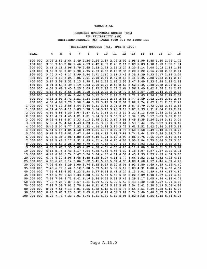
Page A.13.0
TABLE A.5A
REQUIRED STRUCTURAL NUMBER (SNR) 92% RELIABILITY (%R)
RESILIENT MODULUS (MR) RANGE 4000 PSI TO 18000 PSI
RESILIENT MODULUS (MR), (PSI x 1000) ESALD 4 5 6 7 8 9 10 11 12 13 14 15 16 17 18 100 000 3.09 2.83 2.64 2.49 2.36 2.26 2.17 2.09 2.02 1.95 1.90 1.85 1.80 1.76 1.72 150 000 3.30 3.03 2.82 2.66 2.53 2.42 2.32 2.23 2.16 2.09 2.03 1.98 1.93 1.88 1.84 200 000 3.46 3.18 2.96 2.79 2.65 2.53 2.43 2.35 2.27 2.20 2.14 2.08 2.03 1.98 1.93 250 000 3.59 3.30 3.07 2.90 2.75 2.63 2.53 2.43 2.35 2.28 2.22 2.16 2.10 2.05 2.01 300 000 3.70 3.40 3.17 2.99 2.84 2.71 2.60 2.51 2.43 2.35 2.29 2.23 2.17 2.12 2.07 350 000 3.79 3.48 3.25 3.06 2.91 2.78 2.67 2.57 2.49 2.41 2.35 2.28 2.23 2.17 2.13 400 000 3.87 3.56 3.32 3.13 2.98 2.84 2.73 2.63 2.55 2.47 2.40 2.33 2.28 2.22 2.18 450 000 3.94 3.63 3.39 3.19 3.03 2.90 2.78 2.68 2.60 2.52 2.45 2.38 2.32 2.27 2.22 500 000 4.01 3.69 3.45 3.25 3.09 2.95 2.83 2.73 2.64 2.56 2.49 2.42 2.36 2.31 2.26 600 000 4.13 3.80 3.55 3.35 3.18 3.04 2.92 2.82 2.72 2.64 2.57 2.50 2.44 2.38 2.33 700 000 4.23 3.90 3.64 3.44 3.26 3.12 3.00 2.89 2.79 2.71 2.63 2.56 2.50 2.44 2.39 800 000 4.31 3.98 3.72 3.51 3.34 3.19 3.06 2.95 2.86 2.77 2.69 2.62 2.56 2.50 2.44 900 000 4.39 4.06 3.79 3.58 3.40 3.25 3.12 3.01 2.91 2.82 2.74 2.67 2.61 2.55 2.49 1 000 000 4.46 4.12 3.86 3.64 3.46 3.31 3.18 3.06 2.96 2.87 2.79 2.72 2.65 2.59 2.53 1 500 000 4.74 4.39 4.11 3.89 3.70 3.54 3.40 3.28 3.17 3.07 2.99 2.91 2.84 2.77 2.71 2 000 000 4.94 4.58 4.30 4.07 3.87 3.71 3.56 3.44 3.32 3.22 3.13 3.05 2.98 2.91 2.84 2 500 000 5.10 4.74 4.45 4.21 4.01 3.84 3.69 3.56 3.45 3.34 3.25 3.17 3.09 3.02 2.95 3 000 000 5.23 4.86 4.57 4.33 4.13 3.95 3.80 3.67 3.55 3.45 3.35 3.26 3.18 3.11 3.04 3 500 000 5.35 4.97 4.68 4.43 4.23 4.05 3.90 3.76 3.64 3.53 3.44 3.35 3.27 3.19 3.12 4 000 000 5.45 5.07 4.77 4.52 4.32 4.14 3.98 3.84 3.72 3.61 3.51 3.42 3.34 3.26 3.19 4 500 000 5.54 5.15 4.85 4.60 4.39 4.21 4.06 3.92 3.79 3.68 3.58 3.49 3.40 3.33 3.25 5 000 000 5.62 5.23 4.92 4.67 4.46 4.28 4.12 3.98 3.86 3.74 3.64 3.55 3.46 3.38 3.31 6 000 000 5.76 5.36 5.06 4.80 4.59 4.40 4.24 4.10 3.97 3.86 3.75 3.65 3.57 3.49 3.41 7 000 000 5.88 5.48 5.17 4.91 4.69 4.51 4.34 4.20 4.07 3.95 3.84 3.75 3.66 3.57 3.50 8 000 000 5.98 5.58 5.26 5.00 4.79 4.60 4.43 4.29 4.15 4.03 3.93 3.83 3.74 3.65 3.58 9 000 000 6.08 5.67 5.35 5.09 4.87 4.68 4.51 4.36 4.23 4.11 4.00 3.90 3.81 3.72 3.64 10 000 000 6.16 5.75 5.43 5.17 4.94 4.75 4.58 4.43 4.30 4.18 4.07 3.97 3.87 3.79 3.71 15 000 000 6.49 6.07 5.74 5.47 5.24 5.04 4.86 4.71 4.57 4.45 4.33 4.23 4.13 4.04 3.96 20 000 000 6.74 6.30 5.96 5.68 5.45 5.25 5.07 4.91 4.77 4.64 4.52 4.42 4.32 4.22 4.14 25 000 000 6.93 6.49 6.14 5.86 5.62 5.41 5.23 5.07 4.93 4.80 4.68 4.57 4.46 4.37 4.28 30 000 000 7.09 6.64 6.29 6.00 5.76 5.55 5.37 5.20 5.06 4.92 4.80 4.69 4.59 4.49 4.40 35 000 000 7.23 6.77 6.42 6.12 5.88 5.67 5.48 5.32 5.17 5.03 4.91 4.80 4.69 4.60 4.51 40 000 000 7.35 6.89 6.53 6.23 5.98 5.77 5.58 5.41 5.27 5.13 5.01 4.89 4.79 4.69 4.60 45 000 000 7.46 6.99 6.63 6.33 6.08 5.86 5.67 5.50 5.35 5.22 5.09 4.98 4.87 4.77 4.68 50 000 000 7.56 7.09 6.72 6.41 6.16 5.94 5.75 5.58 5.43 5.29 5.17 5.05 4.94 4.84 4.75 60 000 000 7.73 7.25 6.87 6.57 6.31 6.09 5.89 5.72 5.57 5.43 5.30 5.18 5.07 4.97 4.88 70 000 000 7.88 7.39 7.01 6.70 6.44 6.21 6.02 5.84 5.69 5.54 5.41 5.30 5.19 5.08 4.99 80 000 000 8.01 7.51 7.13 6.81 6.55 6.32 6.12 5.95 5.79 5.65 5.51 5.39 5.28 5.18 5.08 90 000 000 8.13 7.63 7.23 6.92 6.65 6.42 6.22 6.04 5.88 5.74 5.60 5.48 5.37 5.27 5.17 100 000 000 8.23 7.73 7.33 7.01 6.74 6.51 6.30 6.12 5.96 5.82 5.68 5.56 5.45 5.34 5.25
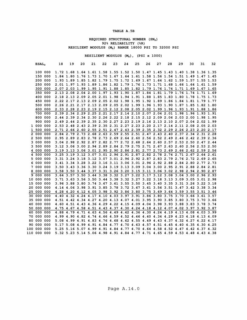
Page A.14.0
TABLE A.5B
REQUIRED STRUCTURAL NUMBER (SNR) 92% RELIABILITY (%R)
RESILIENT MODULUS (MR) RANGE 18000 PSI TO 32000 PSI
RESILIENT MODULUS (MR), (PSI x 1000) ESALD 18 19 20 21 22 23 24 25 26 27 28 29 30 31 32 100 000 1.72 1.68 1.64 1.61 1.58 1.55 1.52 1.50 1.47 1.45 1.43 1.40 1.38 1.36 1.35 150 000 1.84 1.80 1.76 1.73 1.70 1.67 1.64 1.61 1.58 1.56 1.54 1.51 1.49 1.47 1.45 200 000 1.93 1.89 1.85 1.82 1.79 1.75 1.72 1.69 1.67 1.64 1.62 1.59 1.57 1.55 1.53 250 000 2.01 1.97 1.93 1.89 1.86 1.82 1.79 1.76 1.73 1.71 1.68 1.66 1.64 1.61 1.59 300 000 2.07 2.03 1.99 1.95 1.91 1.88 1.85 1.82 1.79 1.76 1.74 1.71 1.69 1.67 1.65 350 000 2.13 2.08 2.04 2.00 1.97 1.93 1.90 1.87 1.84 1.81 1.79 1.76 1.74 1.71 1.69 400 000 2.18 2.13 2.09 2.05 2.01 1.98 1.94 1.91 1.88 1.85 1.83 1.80 1.78 1.75 1.73 450 000 2.22 2.17 2.13 2.09 2.05 2.02 1.98 1.95 1.92 1.89 1.86 1.84 1.81 1.79 1.77 500 000 2.26 2.21 2.17 2.13 2.09 2.05 2.02 1.99 1.96 1.93 1.90 1.87 1.85 1.82 1.80 600 000 2.33 2.28 2.23 2.19 2.15 2.12 2.08 2.05 2.02 1.99 1.96 1.93 1.91 1.88 1.86 700 000 2.39 2.34 2.29 2.25 2.21 2.17 2.14 2.10 2.07 2.04 2.01 1.98 1.96 1.93 1.91 800 000 2.44 2.39 2.34 2.30 2.26 2.22 2.18 2.15 2.12 2.09 2.06 2.03 2.00 1.98 1.95 900 000 2.49 2.44 2.39 2.35 2.30 2.27 2.23 2.19 2.16 2.13 2.10 2.07 2.04 2.02 1.99 1 000 000 2.53 2.48 2.43 2.39 2.35 2.31 2.27 2.23 2.20 2.17 2.14 2.11 2.08 2.05 2.03 1 500 000 2.71 2.66 2.60 2.55 2.51 2.47 2.43 2.39 2.35 2.32 2.29 2.26 2.23 2.20 2.17 2 000 000 2.84 2.79 2.73 2.68 2.63 2.59 2.55 2.51 2.47 2.43 2.40 2.37 2.34 2.31 2.28 2 500 000 2.95 2.89 2.83 2.78 2.73 2.69 2.64 2.60 2.56 2.52 2.49 2.46 2.42 2.39 2.36 3 000 000 3.04 2.98 2.92 2.87 2.82 2.77 2.72 2.68 2.64 2.60 2.57 2.53 2.50 2.47 2.44 3 500 000 3.12 3.06 3.00 2.94 2.89 2.84 2.79 2.75 2.71 2.67 2.63 2.60 2.56 2.53 2.50 4 000 000 3.19 3.13 3.06 3.01 2.95 2.90 2.86 2.81 2.77 2.73 2.69 2.66 2.62 2.59 2.56 4 500 000 3.25 3.19 3.12 3.07 3.01 2.96 2.91 2.87 2.82 2.78 2.74 2.71 2.67 2.64 2.61 5 000 000 3.31 3.24 3.18 3.12 3.07 3.01 2.96 2.92 2.87 2.83 2.79 2.76 2.72 2.69 2.65 6 000 000 3.41 3.34 3.28 3.22 3.16 3.11 3.06 3.01 2.96 2.92 2.88 2.84 2.80 2.77 2.73 7 000 000 3.50 3.43 3.36 3.30 3.24 3.19 3.13 3.09 3.04 3.00 2.95 2.91 2.88 2.84 2.81 8 000 000 3.58 3.50 3.44 3.37 3.31 3.26 3.20 3.15 3.11 3.06 3.02 2.98 2.94 2.90 2.87 9 000 000 3.64 3.57 3.50 3.44 3.38 3.32 3.27 3.22 3.17 3.12 3.08 3.04 3.00 2.96 2.93 10 000 000 3.71 3.63 3.56 3.50 3.44 3.38 3.32 3.27 3.22 3.18 3.13 3.09 3.05 3.01 2.98 15 000 000 3.96 3.88 3.80 3.74 3.67 3.61 3.55 3.50 3.45 3.40 3.35 3.31 3.26 3.22 3.18 20 000 000 4.14 4.06 3.98 3.91 3.85 3.78 3.72 3.67 3.61 3.56 3.51 3.47 3.42 3.38 3.34 25 000 000 4.28 4.20 4.12 4.05 3.98 3.92 3.86 3.80 3.75 3.69 3.64 3.59 3.55 3.51 3.46 30 000 000 4.40 4.32 4.24 4.17 4.10 4.03 3.97 3.91 3.86 3.80 3.75 3.70 3.66 3.61 3.57 35 000 000 4.51 4.42 4.34 4.27 4.20 4.13 4.07 4.01 3.95 3.90 3.85 3.80 3.75 3.70 3.66 40 000 000 4.60 4.51 4.43 4.36 4.29 4.22 4.15 4.09 4.04 3.98 3.93 3.88 3.83 3.78 3.74 50 000 000 4.75 4.67 4.58 4.51 4.43 4.37 4.30 4.24 4.18 4.12 4.07 4.02 3.97 3.92 3.87 60 000 000 4.88 4.79 4.71 4.63 4.56 4.49 4.42 4.36 4.30 4.24 4.19 4.13 4.08 4.03 3.99 70 000 000 4.99 4.90 4.82 4.74 4.66 4.59 4.52 4.46 4.40 4.34 4.29 4.23 4.18 4.13 4.09 80 000 000 5.08 4.99 4.91 4.83 4.76 4.68 4.62 4.55 4.49 4.43 4.37 4.32 4.27 4.22 4.17 90 000 000 5.17 5.08 4.99 4.91 4.84 4.77 4.70 4.63 4.57 4.51 4.45 4.40 4.35 4.30 4.25 100 000 000 5.25 5.16 5.07 4.99 4.91 4.84 4.77 4.70 4.64 4.58 4.52 4.47 4.42 4.37 4.32 110 000 000 5.32 5.23 5.14 5.06 4.98 4.91 4.84 4.77 4.71 4.65 4.59 4.53 4.48 4.43 4.38
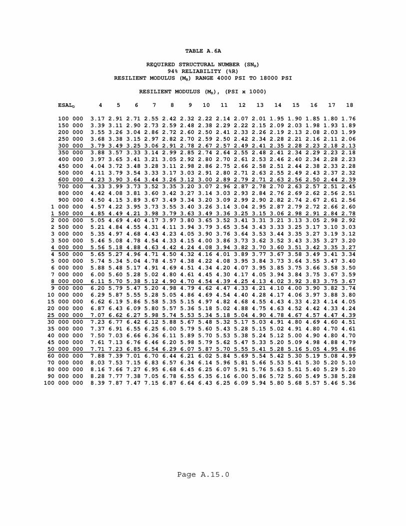
Page A.15.0
TABLE A.6A
REQUIRED STRUCTURAL NUMBER (SNR) 94% RELIABILITY (%R)
RESILIENT MODULUS (MR) RANGE 4000 PSI TO 18000 PSI
RESILIENT MODULUS (MR), (PSI x 1000) ESALD 4 5 6 7 8 9 10 11 12 13 14 15 16 17 18 100 000 3.17 2.91 2.71 2.55 2.42 2.32 2.22 2.14 2.07 2.01 1.95 1.90 1.85 1.80 1.76 150 000 3.39 3.11 2.90 2.73 2.59 2.48 2.38 2.29 2.22 2.15 2.09 2.03 1.98 1.93 1.89 200 000 3.55 3.26 3.04 2.86 2.72 2.60 2.50 2.41 2.33 2.26 2.19 2.13 2.08 2.03 1.99 250 000 3.68 3.38 3.15 2.97 2.82 2.70 2.59 2.50 2.42 2.34 2.28 2.21 2.16 2.11 2.06 300 000 3.79 3.49 3.25 3.06 2.91 2.78 2.67 2.57 2.49 2.41 2.35 2.28 2.23 2.18 2.13 350 000 3.88 3.57 3.33 3.14 2.99 2.85 2.74 2.64 2.55 2.48 2.41 2.34 2.29 2.23 2.18 400 000 3.97 3.65 3.41 3.21 3.05 2.92 2.80 2.70 2.61 2.53 2.46 2.40 2.34 2.28 2.23 450 000 4.04 3.72 3.48 3.28 3.11 2.98 2.86 2.75 2.66 2.58 2.51 2.44 2.38 2.33 2.28 500 000 4.11 3.79 3.54 3.33 3.17 3.03 2.91 2.80 2.71 2.63 2.55 2.49 2.43 2.37 2.32 600 000 4.23 3.90 3.64 3.44 3.26 3.12 3.00 2.89 2.79 2.71 2.63 2.56 2.50 2.44 2.39 700 000 4.33 3.99 3.73 3.52 3.35 3.20 3.07 2.96 2.87 2.78 2.70 2.63 2.57 2.51 2.45 800 000 4.42 4.08 3.81 3.60 3.42 3.27 3.14 3.03 2.93 2.84 2.76 2.69 2.62 2.56 2.51 900 000 4.50 4.15 3.89 3.67 3.49 3.34 3.20 3.09 2.99 2.90 2.82 2.74 2.67 2.61 2.56 1 000 000 4.57 4.22 3.95 3.73 3.55 3.40 3.26 3.14 3.04 2.95 2.87 2.79 2.72 2.66 2.60 1 500 000 4.85 4.49 4.21 3.98 3.79 3.63 3.49 3.36 3.25 3.15 3.06 2.98 2.91 2.84 2.78 2 000 000 5.05 4.69 4.40 4.17 3.97 3.80 3.65 3.52 3.41 3.31 3.21 3.13 3.05 2.98 2.92 2 500 000 5.21 4.84 4.55 4.31 4.11 3.94 3.79 3.65 3.54 3.43 3.33 3.25 3.17 3.10 3.03 3 000 000 5.35 4.97 4.68 4.43 4.23 4.05 3.90 3.76 3.64 3.53 3.44 3.35 3.27 3.19 3.12 3 500 000 5.46 5.08 4.78 4.54 4.33 4.15 4.00 3.86 3.73 3.62 3.52 3.43 3.35 3.27 3.20 4 000 000 5.56 5.18 4.88 4.63 4.42 4.24 4.08 3.94 3.82 3.70 3.60 3.51 3.42 3.35 3.27 4 500 000 5.65 5.27 4.96 4.71 4.50 4.32 4.16 4.01 3.89 3.77 3.67 3.58 3.49 3.41 3.34 5 000 000 5.74 5.34 5.04 4.78 4.57 4.38 4.22 4.08 3.95 3.84 3.73 3.64 3.55 3.47 3.40 6 000 000 5.88 5.48 5.17 4.91 4.69 4.51 4.34 4.20 4.07 3.95 3.85 3.75 3.66 3.58 3.50 7 000 000 6.00 5.60 5.28 5.02 4.80 4.61 4.45 4.30 4.17 4.05 3.94 3.84 3.75 3.67 3.59 8 000 000 6.11 5.70 5.38 5.12 4.90 4.70 4.54 4.39 4.25 4.13 4.02 3.92 3.83 3.75 3.67 9 000 000 6.20 5.79 5.47 5.20 4.98 4.79 4.62 4.47 4.33 4.21 4.10 4.00 3.90 3.82 3.74 10 000 000 6.29 5.87 5.55 5.28 5.05 4.86 4.69 4.54 4.40 4.28 4.17 4.06 3.97 3.88 3.80 15 000 000 6.62 6.19 5.86 5.58 5.35 5.15 4.97 4.82 4.68 4.55 4.43 4.33 4.23 4.14 4.05 20 000 000 6.87 6.43 6.09 5.80 5.57 5.36 5.18 5.02 4.88 4.75 4.63 4.52 4.42 4.33 4.24 25 000 000 7.07 6.62 6.27 5.98 5.74 5.53 5.34 5.18 5.04 4.90 4.78 4.67 4.57 4.47 4.39 30 000 000 7.23 6.77 6.42 6.12 5.88 5.67 5.48 5.32 5.17 5.03 4.91 4.80 4.69 4.60 4.51 35 000 000 7.37 6.91 6.55 6.25 6.00 5.79 5.60 5.43 5.28 5.15 5.02 4.91 4.80 4.70 4.61 40 000 000 7.50 7.03 6.66 6.36 6.11 5.89 5.70 5.53 5.38 5.24 5.12 5.00 4.90 4.80 4.70 45 000 000 7.61 7.13 6.76 6.46 6.20 5.98 5.79 5.62 5.47 5.33 5.20 5.09 4.98 4.88 4.79 50 000 000 7.71 7.23 6.85 6.54 6.29 6.07 5.87 5.70 5.55 5.41 5.28 5.16 5.05 4.95 4.86 60 000 000 7.88 7.39 7.01 6.70 6.44 6.21 6.02 5.84 5.69 5.54 5.42 5.30 5.19 5.08 4.99 70 000 000 8.03 7.53 7.15 6.83 6.57 6.34 6.14 5.96 5.81 5.66 5.53 5.41 5.30 5.20 5.10 80 000 000 8.16 7.66 7.27 6.95 6.68 6.45 6.25 6.07 5.91 5.76 5.63 5.51 5.40 5.29 5.20 90 000 000 8.28 7.77 7.38 7.05 6.78 6.55 6.35 6.16 6.00 5.86 5.72 5.60 5.49 5.38 5.28 100 000 000 8.39 7.87 7.47 7.15 6.87 6.64 6.43 6.25 6.09 5.94 5.80 5.68 5.57 5.46 5.36

Page A.16.0
TABLE A.6B
REQUIRED STRUCTURAL NUMBER (SNR) 94% RELIABILITY (%R)
RESILIENT MODULUS (MR) RANGE 18000 PSI TO 32000 PSI
RESILIENT MODULUS (MR), (PSI x 1000) ESALD 18 19 20 21 22 23 24 25 26 27 28 29 30 31 32 100 000 1.76 1.72 1.69 1.66 1.62 1.59 1.57 1.54 1.51 1.49 1.47 1.45 1.42 1.40 1.39 150 000 1.89 1.85 1.81 1.78 1.74 1.71 1.68 1.66 1.63 1.60 1.58 1.56 1.53 1.51 1.49 200 000 1.99 1.94 1.90 1.87 1.83 1.80 1.77 1.74 1.71 1.69 1.66 1.64 1.62 1.59 1.57 250 000 2.06 2.02 1.98 1.94 1.91 1.87 1.84 1.81 1.78 1.76 1.73 1.70 1.68 1.66 1.64 300 000 2.13 2.08 2.04 2.00 1.97 1.93 1.90 1.87 1.84 1.81 1.79 1.76 1.74 1.71 1.69 350 000 2.18 2.14 2.10 2.06 2.02 1.98 1.95 1.92 1.89 1.86 1.83 1.81 1.78 1.76 1.74 400 000 2.23 2.19 2.14 2.10 2.06 2.03 1.99 1.96 1.93 1.90 1.88 1.85 1.83 1.80 1.78 450 000 2.28 2.23 2.19 2.14 2.11 2.07 2.04 2.00 1.97 1.94 1.91 1.89 1.86 1.84 1.82 500 000 2.32 2.27 2.22 2.18 2.14 2.11 2.07 2.04 2.01 1.98 1.95 1.92 1.90 1.87 1.85 600 000 2.39 2.34 2.29 2.25 2.21 2.17 2.14 2.10 2.07 2.04 2.01 1.98 1.96 1.93 1.91 700 000 2.45 2.40 2.35 2.31 2.27 2.23 2.19 2.16 2.13 2.09 2.06 2.04 2.01 1.98 1.96 800 000 2.51 2.45 2.41 2.36 2.32 2.28 2.24 2.21 2.17 2.14 2.11 2.08 2.06 2.03 2.00 900 000 2.56 2.50 2.45 2.41 2.37 2.32 2.29 2.25 2.22 2.18 2.15 2.12 2.10 2.07 2.04 1 000 000 2.60 2.55 2.50 2.45 2.41 2.37 2.33 2.29 2.26 2.22 2.19 2.16 2.13 2.11 2.08 1 500 000 2.78 2.72 2.67 2.62 2.58 2.53 2.49 2.45 2.41 2.38 2.35 2.31 2.28 2.26 2.23 2 000 000 2.92 2.86 2.80 2.75 2.70 2.66 2.61 2.57 2.53 2.50 2.46 2.43 2.40 2.37 2.34 2 500 000 3.03 2.97 2.91 2.85 2.80 2.76 2.71 2.67 2.63 2.59 2.55 2.52 2.49 2.46 2.43 3 000 000 3.12 3.06 3.00 2.94 2.89 2.84 2.79 2.75 2.71 2.67 2.63 2.60 2.56 2.53 2.50 3 500 000 3.20 3.14 3.07 3.02 2.96 2.91 2.87 2.82 2.78 2.74 2.70 2.66 2.63 2.60 2.57 4 000 000 3.27 3.21 3.14 3.09 3.03 2.98 2.93 2.89 2.84 2.80 2.76 2.72 2.69 2.66 2.62 4 500 000 3.34 3.27 3.21 3.15 3.09 3.04 2.99 2.94 2.90 2.86 2.82 2.78 2.74 2.71 2.68 5 000 000 3.40 3.33 3.26 3.20 3.14 3.09 3.04 2.99 2.95 2.91 2.87 2.83 2.79 2.76 2.72 6 000 000 3.50 3.43 3.36 3.30 3.24 3.19 3.13 3.09 3.04 3.00 2.95 2.91 2.88 2.84 2.81 7 000 000 3.59 3.52 3.45 3.38 3.32 3.27 3.22 3.17 3.12 3.07 3.03 2.99 2.95 2.91 2.88 8 000 000 3.67 3.59 3.52 3.46 3.40 3.34 3.29 3.24 3.19 3.14 3.10 3.06 3.02 2.98 2.94 9 000 000 3.74 3.66 3.59 3.53 3.46 3.41 3.35 3.30 3.25 3.20 3.16 3.12 3.08 3.04 3.00 10 000 000 3.80 3.73 3.65 3.59 3.52 3.47 3.41 3.36 3.31 3.26 3.22 3.17 3.13 3.09 3.05 15 000 000 4.05 3.97 3.90 3.83 3.76 3.70 3.64 3.59 3.54 3.48 3.44 3.39 3.35 3.31 3.27 20 000 000 4.24 4.16 4.08 4.01 3.94 3.88 3.82 3.76 3.70 3.65 3.60 3.56 3.51 3.47 3.42 25 000 000 4.39 4.30 4.22 4.15 4.08 4.02 3.95 3.90 3.84 3.79 3.74 3.69 3.64 3.59 3.55 30 000 000 4.51 4.42 4.34 4.27 4.20 4.13 4.07 4.01 3.95 3.90 3.85 3.80 3.75 3.70 3.66 35 000 000 4.61 4.53 4.45 4.37 4.30 4.23 4.17 4.11 4.05 3.99 3.94 3.89 3.84 3.80 3.75 40 000 000 4.70 4.62 4.54 4.46 4.39 4.32 4.26 4.19 4.13 4.08 4.03 3.97 3.92 3.88 3.83 45 000 000 4.79 4.70 4.62 4.54 4.47 4.40 4.33 4.27 4.21 4.15 4.10 4.05 4.00 3.95 3.90 50 000 000 4.86 4.77 4.69 4.61 4.54 4.47 4.40 4.34 4.28 4.22 4.17 4.12 4.07 4.02 3.97 60 000 000 4.99 4.90 4.82 4.74 4.66 4.59 4.53 4.46 4.40 4.34 4.29 4.23 4.18 4.13 4.09 70 000 000 5.10 5.01 4.93 4.85 4.77 4.70 4.63 4.57 4.50 4.45 4.39 4.33 4.28 4.23 4.19 80 000 000 5.20 5.11 5.02 4.94 4.86 4.79 4.72 4.66 4.60 4.54 4.48 4.42 4.37 4.32 4.27 90 000 000 5.28 5.19 5.11 5.02 4.95 4.87 4.80 4.74 4.68 4.62 4.56 4.50 4.45 4.40 4.35 100 000 000 5.36 5.27 5.18 5.10 5.02 4.95 4.88 4.81 4.75 4.69 4.63 4.57 4.52 4.47 4.42
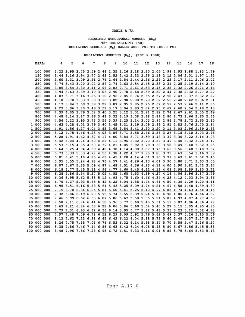
Page A.17.0
TABLE A.7A
REQUIRED STRUCTURAL NUMBER (SNR) 95% RELIABILITY (%R)
RESILIENT MODULUS (MR) RANGE 4000 PSI TO 18000 PSI
RESILIENT MODULUS (MR), (PSI x 1000) ESALD 4 5 6 7 8 9 10 11 12 13 14 15 16 17 18 100 000 3.22 2.95 2.75 2.59 2.46 2.35 2.26 2.18 2.10 2.04 1.98 1.93 1.88 1.83 1.79 150 000 3.44 3.16 2.94 2.77 2.63 2.52 2.42 2.33 2.25 2.18 2.12 2.06 2.01 1.97 1.92 200 000 3.60 3.31 3.09 2.91 2.76 2.64 2.54 2.44 2.36 2.29 2.23 2.17 2.11 2.06 2.02 250 000 3.74 3.43 3.20 3.02 2.87 2.74 2.63 2.54 2.45 2.38 2.31 2.25 2.19 2.14 2.10 300 000 3.85 3.54 3.30 3.11 2.96 2.83 2.71 2.61 2.53 2.45 2.38 2.32 2.26 2.21 2.16 350 000 3.94 3.63 3.39 3.19 3.03 2.90 2.78 2.68 2.59 2.52 2.44 2.38 2.32 2.27 2.22 400 000 4.03 3.71 3.46 3.26 3.10 2.96 2.85 2.74 2.65 2.57 2.50 2.43 2.37 2.32 2.27 450 000 4.10 3.78 3.53 3.33 3.16 3.02 2.90 2.80 2.70 2.62 2.55 2.48 2.42 2.36 2.31 500 000 4.17 3.84 3.59 3.39 3.22 3.07 2.95 2.85 2.75 2.67 2.59 2.53 2.46 2.41 2.35 600 000 4.29 3.96 3.70 3.49 3.32 3.17 3.04 2.93 2.84 2.75 2.67 2.60 2.54 2.48 2.43 700 000 4.39 4.05 3.79 3.58 3.40 3.25 3.12 3.01 2.91 2.82 2.74 2.67 2.61 2.55 2.49 800 000 4.48 4.14 3.87 3.66 3.48 3.32 3.19 3.08 2.98 2.89 2.80 2.73 2.66 2.60 2.55 900 000 4.56 4.22 3.95 3.73 3.54 3.39 3.25 3.14 3.03 2.94 2.86 2.78 2.72 2.65 2.60 1 000 000 4.63 4.28 4.01 3.79 3.60 3.45 3.31 3.19 3.09 2.99 2.91 2.83 2.76 2.70 2.64 1 500 000 4.91 4.56 4.27 4.04 3.85 3.68 3.54 3.41 3.30 3.20 3.11 3.03 2.96 2.89 2.83 2 000 000 5.12 4.75 4.46 4.23 4.03 3.86 3.71 3.58 3.46 3.36 3.26 3.18 3.10 3.03 2.96 2 500 000 5.28 4.91 4.62 4.37 4.17 4.00 3.84 3.71 3.59 3.48 3.39 3.30 3.22 3.14 3.08 3 000 000 5.42 5.04 4.74 4.50 4.29 4.11 3.96 3.82 3.70 3.59 3.49 3.40 3.32 3.24 3.17 3 500 000 5.53 5.15 4.85 4.60 4.39 4.21 4.05 3.92 3.79 3.68 3.58 3.49 3.40 3.32 3.25 4 000 000 5.64 5.25 4.94 4.69 4.48 4.30 4.14 4.00 3.87 3.76 3.66 3.56 3.48 3.40 3.32 4 500 000 5.73 5.33 5.03 4.77 4.56 4.38 4.22 4.07 3.95 3.83 3.73 3.63 3.54 3.46 3.39 5 000 000 5.81 5.41 5.10 4.85 4.63 4.45 4.28 4.14 4.01 3.90 3.79 3.69 3.61 3.52 3.45 6 000 000 5.95 5.55 5.24 4.98 4.76 4.57 4.41 4.26 4.13 4.01 3.90 3.80 3.71 3.63 3.55 7 000 000 6.07 5.67 5.35 5.09 4.87 4.68 4.51 4.36 4.23 4.11 4.00 3.90 3.81 3.72 3.64 8 000 000 6.18 5.77 5.45 5.18 4.96 4.77 4.60 4.45 4.32 4.19 4.08 3.98 3.89 3.80 3.72 9 000 000 6.28 5.86 5.54 5.27 5.05 4.85 4.68 4.53 4.39 4.27 4.16 4.06 3.96 3.87 3.79 10 000 000 6.36 5.95 5.62 5.35 5.12 4.93 4.75 4.60 4.46 4.34 4.23 4.12 4.03 3.94 3.86 15 000 000 6.70 6.27 5.93 5.65 5.42 5.22 5.04 4.88 4.74 4.61 4.50 4.39 4.29 4.20 4.11 20 000 000 6.95 6.51 6.16 5.88 5.64 5.43 5.25 5.09 4.94 4.81 4.69 4.58 4.48 4.39 4.30 25 000 000 7.15 6.70 6.34 6.05 5.81 5.60 5.41 5.25 5.10 4.97 4.85 4.74 4.63 4.54 4.45 30 000 000 7.32 6.86 6.49 6.20 5.95 5.74 5.55 5.39 5.24 5.10 4.98 4.86 4.76 4.66 4.57 35 000 000 7.46 6.99 6.62 6.33 6.07 5.86 5.67 5.50 5.35 5.21 5.09 4.97 4.87 4.77 4.68 40 000 000 7.58 7.11 6.74 6.44 6.18 5.96 5.77 5.60 5.45 5.31 5.19 5.07 4.96 4.86 4.77 45 000 000 7.69 7.21 6.84 6.53 6.28 6.06 5.86 5.69 5.54 5.40 5.27 5.15 5.05 4.95 4.85 50 000 000 7.79 7.31 6.93 6.62 6.36 6.14 5.95 5.77 5.62 5.48 5.35 5.23 5.12 5.02 4.93 60 000 000 7.97 7.48 7.09 6.78 6.52 6.29 6.09 5.92 5.76 5.62 5.49 5.37 5.26 5.15 5.06 70 000 000 8.12 7.62 7.23 6.91 6.65 6.42 6.22 6.04 5.88 5.73 5.60 5.48 5.37 5.27 5.17 80 000 000 8.26 7.75 7.35 7.03 6.76 6.53 6.32 6.14 5.98 5.84 5.70 5.58 5.47 5.36 5.27 90 000 000 8.38 7.86 7.46 7.14 6.86 6.63 6.42 6.24 6.08 5.93 5.80 5.67 5.56 5.45 5.35 100 000 000 8.48 7.96 7.56 7.23 6.95 6.72 6.51 6.33 6.16 6.01 5.88 5.75 5.64 5.53 5.43
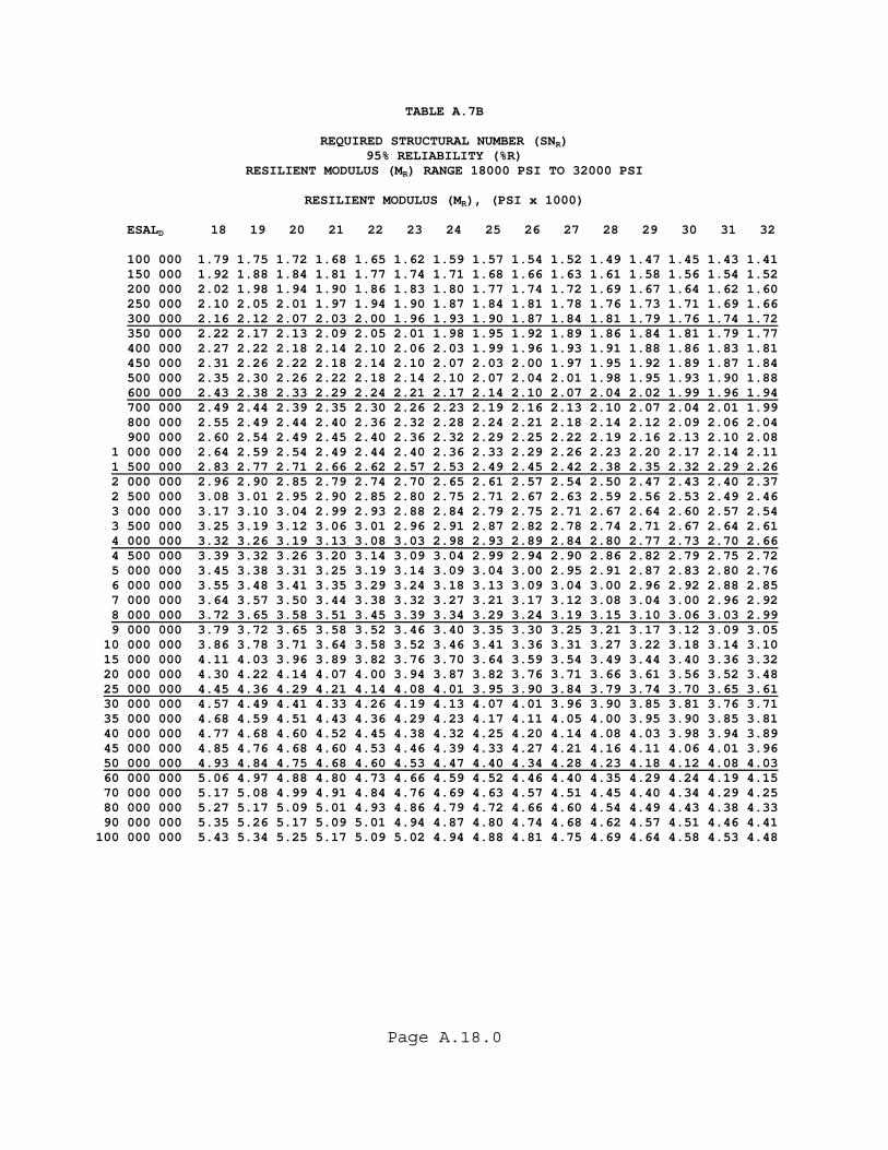
Page A.18.0
TABLE A.7B
REQUIRED STRUCTURAL NUMBER (SNR) 95% RELIABILITY (%R)
RESILIENT MODULUS (MR) RANGE 18000 PSI TO 32000 PSI
RESILIENT MODULUS (MR), (PSI x 1000) ESALD 18 19 20 21 22 23 24 25 26 27 28 29 30 31 32 100 000 1.79 1.75 1.72 1.68 1.65 1.62 1.59 1.57 1.54 1.52 1.49 1.47 1.45 1.43 1.41 150 000 1.92 1.88 1.84 1.81 1.77 1.74 1.71 1.68 1.66 1.63 1.61 1.58 1.56 1.54 1.52 200 000 2.02 1.98 1.94 1.90 1.86 1.83 1.80 1.77 1.74 1.72 1.69 1.67 1.64 1.62 1.60 250 000 2.10 2.05 2.01 1.97 1.94 1.90 1.87 1.84 1.81 1.78 1.76 1.73 1.71 1.69 1.66 300 000 2.16 2.12 2.07 2.03 2.00 1.96 1.93 1.90 1.87 1.84 1.81 1.79 1.76 1.74 1.72 350 000 2.22 2.17 2.13 2.09 2.05 2.01 1.98 1.95 1.92 1.89 1.86 1.84 1.81 1.79 1.77 400 000 2.27 2.22 2.18 2.14 2.10 2.06 2.03 1.99 1.96 1.93 1.91 1.88 1.86 1.83 1.81 450 000 2.31 2.26 2.22 2.18 2.14 2.10 2.07 2.03 2.00 1.97 1.95 1.92 1.89 1.87 1.84 500 000 2.35 2.30 2.26 2.22 2.18 2.14 2.10 2.07 2.04 2.01 1.98 1.95 1.93 1.90 1.88 600 000 2.43 2.38 2.33 2.29 2.24 2.21 2.17 2.14 2.10 2.07 2.04 2.02 1.99 1.96 1.94 700 000 2.49 2.44 2.39 2.35 2.30 2.26 2.23 2.19 2.16 2.13 2.10 2.07 2.04 2.01 1.99 800 000 2.55 2.49 2.44 2.40 2.36 2.32 2.28 2.24 2.21 2.18 2.14 2.12 2.09 2.06 2.04 900 000 2.60 2.54 2.49 2.45 2.40 2.36 2.32 2.29 2.25 2.22 2.19 2.16 2.13 2.10 2.08 1 000 000 2.64 2.59 2.54 2.49 2.44 2.40 2.36 2.33 2.29 2.26 2.23 2.20 2.17 2.14 2.11 1 500 000 2.83 2.77 2.71 2.66 2.62 2.57 2.53 2.49 2.45 2.42 2.38 2.35 2.32 2.29 2.26 2 000 000 2.96 2.90 2.85 2.79 2.74 2.70 2.65 2.61 2.57 2.54 2.50 2.47 2.43 2.40 2.37 2 500 000 3.08 3.01 2.95 2.90 2.85 2.80 2.75 2.71 2.67 2.63 2.59 2.56 2.53 2.49 2.46 3 000 000 3.17 3.10 3.04 2.99 2.93 2.88 2.84 2.79 2.75 2.71 2.67 2.64 2.60 2.57 2.54 3 500 000 3.25 3.19 3.12 3.06 3.01 2.96 2.91 2.87 2.82 2.78 2.74 2.71 2.67 2.64 2.61 4 000 000 3.32 3.26 3.19 3.13 3.08 3.03 2.98 2.93 2.89 2.84 2.80 2.77 2.73 2.70 2.66 4 500 000 3.39 3.32 3.26 3.20 3.14 3.09 3.04 2.99 2.94 2.90 2.86 2.82 2.79 2.75 2.72 5 000 000 3.45 3.38 3.31 3.25 3.19 3.14 3.09 3.04 3.00 2.95 2.91 2.87 2.83 2.80 2.76 6 000 000 3.55 3.48 3.41 3.35 3.29 3.24 3.18 3.13 3.09 3.04 3.00 2.96 2.92 2.88 2.85 7 000 000 3.64 3.57 3.50 3.44 3.38 3.32 3.27 3.21 3.17 3.12 3.08 3.04 3.00 2.96 2.92 8 000 000 3.72 3.65 3.58 3.51 3.45 3.39 3.34 3.29 3.24 3.19 3.15 3.10 3.06 3.03 2.99 9 000 000 3.79 3.72 3.65 3.58 3.52 3.46 3.40 3.35 3.30 3.25 3.21 3.17 3.12 3.09 3.05 10 000 000 3.86 3.78 3.71 3.64 3.58 3.52 3.46 3.41 3.36 3.31 3.27 3.22 3.18 3.14 3.10 15 000 000 4.11 4.03 3.96 3.89 3.82 3.76 3.70 3.64 3.59 3.54 3.49 3.44 3.40 3.36 3.32 20 000 000 4.30 4.22 4.14 4.07 4.00 3.94 3.87 3.82 3.76 3.71 3.66 3.61 3.56 3.52 3.48 25 000 000 4.45 4.36 4.29 4.21 4.14 4.08 4.01 3.95 3.90 3.84 3.79 3.74 3.70 3.65 3.61 30 000 000 4.57 4.49 4.41 4.33 4.26 4.19 4.13 4.07 4.01 3.96 3.90 3.85 3.81 3.76 3.71 35 000 000 4.68 4.59 4.51 4.43 4.36 4.29 4.23 4.17 4.11 4.05 4.00 3.95 3.90 3.85 3.81 40 000 000 4.77 4.68 4.60 4.52 4.45 4.38 4.32 4.25 4.20 4.14 4.08 4.03 3.98 3.94 3.89 45 000 000 4.85 4.76 4.68 4.60 4.53 4.46 4.39 4.33 4.27 4.21 4.16 4.11 4.06 4.01 3.96 50 000 000 4.93 4.84 4.75 4.68 4.60 4.53 4.47 4.40 4.34 4.28 4.23 4.18 4.12 4.08 4.03 60 000 000 5.06 4.97 4.88 4.80 4.73 4.66 4.59 4.52 4.46 4.40 4.35 4.29 4.24 4.19 4.15 70 000 000 5.17 5.08 4.99 4.91 4.84 4.76 4.69 4.63 4.57 4.51 4.45 4.40 4.34 4.29 4.25 80 000 000 5.27 5.17 5.09 5.01 4.93 4.86 4.79 4.72 4.66 4.60 4.54 4.49 4.43 4.38 4.33 90 000 000 5.35 5.26 5.17 5.09 5.01 4.94 4.87 4.80 4.74 4.68 4.62 4.57 4.51 4.46 4.41 100 000 000 5.43 5.34 5.25 5.17 5.09 5.02 4.94 4.88 4.81 4.75 4.69 4.64 4.58 4.53 4.48
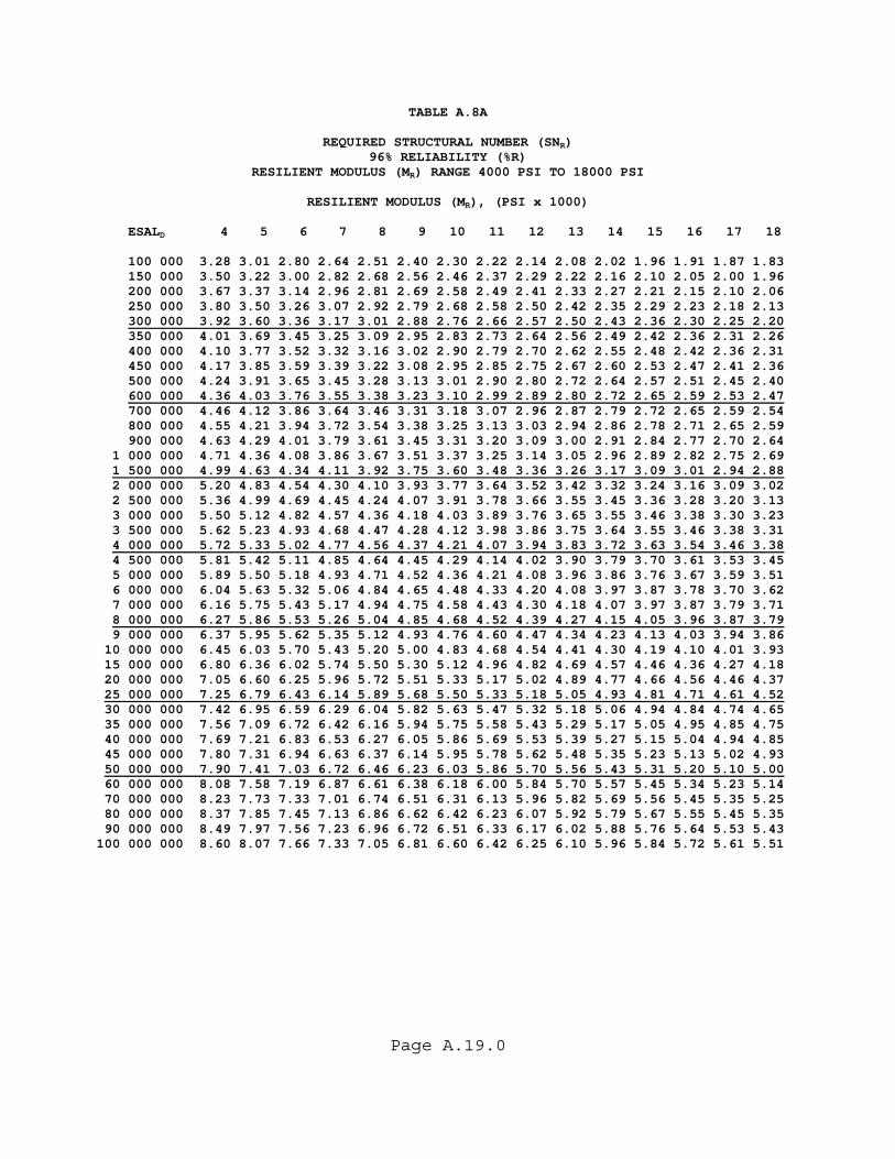
Page A.19.0
TABLE A.8A
REQUIRED STRUCTURAL NUMBER (SNR) 96% RELIABILITY (%R)
RESILIENT MODULUS (MR) RANGE 4000 PSI TO 18000 PSI
RESILIENT MODULUS (MR), (PSI x 1000) ESALD 4 5 6 7 8 9 10 11 12 13 14 15 16 17 18 100 000 3.28 3.01 2.80 2.64 2.51 2.40 2.30 2.22 2.14 2.08 2.02 1.96 1.91 1.87 1.83 150 000 3.50 3.22 3.00 2.82 2.68 2.56 2.46 2.37 2.29 2.22 2.16 2.10 2.05 2.00 1.96 200 000 3.67 3.37 3.14 2.96 2.81 2.69 2.58 2.49 2.41 2.33 2.27 2.21 2.15 2.10 2.06 250 000 3.80 3.50 3.26 3.07 2.92 2.79 2.68 2.58 2.50 2.42 2.35 2.29 2.23 2.18 2.13 300 000 3.92 3.60 3.36 3.17 3.01 2.88 2.76 2.66 2.57 2.50 2.43 2.36 2.30 2.25 2.20 350 000 4.01 3.69 3.45 3.25 3.09 2.95 2.83 2.73 2.64 2.56 2.49 2.42 2.36 2.31 2.26 400 000 4.10 3.77 3.52 3.32 3.16 3.02 2.90 2.79 2.70 2.62 2.55 2.48 2.42 2.36 2.31 450 000 4.17 3.85 3.59 3.39 3.22 3.08 2.95 2.85 2.75 2.67 2.60 2.53 2.47 2.41 2.36 500 000 4.24 3.91 3.65 3.45 3.28 3.13 3.01 2.90 2.80 2.72 2.64 2.57 2.51 2.45 2.40 600 000 4.36 4.03 3.76 3.55 3.38 3.23 3.10 2.99 2.89 2.80 2.72 2.65 2.59 2.53 2.47 700 000 4.46 4.12 3.86 3.64 3.46 3.31 3.18 3.07 2.96 2.87 2.79 2.72 2.65 2.59 2.54 800 000 4.55 4.21 3.94 3.72 3.54 3.38 3.25 3.13 3.03 2.94 2.86 2.78 2.71 2.65 2.59 900 000 4.63 4.29 4.01 3.79 3.61 3.45 3.31 3.20 3.09 3.00 2.91 2.84 2.77 2.70 2.64 1 000 000 4.71 4.36 4.08 3.86 3.67 3.51 3.37 3.25 3.14 3.05 2.96 2.89 2.82 2.75 2.69 1 500 000 4.99 4.63 4.34 4.11 3.92 3.75 3.60 3.48 3.36 3.26 3.17 3.09 3.01 2.94 2.88 2 000 000 5.20 4.83 4.54 4.30 4.10 3.93 3.77 3.64 3.52 3.42 3.32 3.24 3.16 3.09 3.02 2 500 000 5.36 4.99 4.69 4.45 4.24 4.07 3.91 3.78 3.66 3.55 3.45 3.36 3.28 3.20 3.13 3 000 000 5.50 5.12 4.82 4.57 4.36 4.18 4.03 3.89 3.76 3.65 3.55 3.46 3.38 3.30 3.23 3 500 000 5.62 5.23 4.93 4.68 4.47 4.28 4.12 3.98 3.86 3.75 3.64 3.55 3.46 3.38 3.31 4 000 000 5.72 5.33 5.02 4.77 4.56 4.37 4.21 4.07 3.94 3.83 3.72 3.63 3.54 3.46 3.38 4 500 000 5.81 5.42 5.11 4.85 4.64 4.45 4.29 4.14 4.02 3.90 3.79 3.70 3.61 3.53 3.45 5 000 000 5.89 5.50 5.18 4.93 4.71 4.52 4.36 4.21 4.08 3.96 3.86 3.76 3.67 3.59 3.51 6 000 000 6.04 5.63 5.32 5.06 4.84 4.65 4.48 4.33 4.20 4.08 3.97 3.87 3.78 3.70 3.62 7 000 000 6.16 5.75 5.43 5.17 4.94 4.75 4.58 4.43 4.30 4.18 4.07 3.97 3.87 3.79 3.71 8 000 000 6.27 5.86 5.53 5.26 5.04 4.85 4.68 4.52 4.39 4.27 4.15 4.05 3.96 3.87 3.79 9 000 000 6.37 5.95 5.62 5.35 5.12 4.93 4.76 4.60 4.47 4.34 4.23 4.13 4.03 3.94 3.86 10 000 000 6.45 6.03 5.70 5.43 5.20 5.00 4.83 4.68 4.54 4.41 4.30 4.19 4.10 4.01 3.93 15 000 000 6.80 6.36 6.02 5.74 5.50 5.30 5.12 4.96 4.82 4.69 4.57 4.46 4.36 4.27 4.18 20 000 000 7.05 6.60 6.25 5.96 5.72 5.51 5.33 5.17 5.02 4.89 4.77 4.66 4.56 4.46 4.37 25 000 000 7.25 6.79 6.43 6.14 5.89 5.68 5.50 5.33 5.18 5.05 4.93 4.81 4.71 4.61 4.52 30 000 000 7.42 6.95 6.59 6.29 6.04 5.82 5.63 5.47 5.32 5.18 5.06 4.94 4.84 4.74 4.65 35 000 000 7.56 7.09 6.72 6.42 6.16 5.94 5.75 5.58 5.43 5.29 5.17 5.05 4.95 4.85 4.75 40 000 000 7.69 7.21 6.83 6.53 6.27 6.05 5.86 5.69 5.53 5.39 5.27 5.15 5.04 4.94 4.85 45 000 000 7.80 7.31 6.94 6.63 6.37 6.14 5.95 5.78 5.62 5.48 5.35 5.23 5.13 5.02 4.93 50 000 000 7.90 7.41 7.03 6.72 6.46 6.23 6.03 5.86 5.70 5.56 5.43 5.31 5.20 5.10 5.00 60 000 000 8.08 7.58 7.19 6.87 6.61 6.38 6.18 6.00 5.84 5.70 5.57 5.45 5.34 5.23 5.14 70 000 000 8.23 7.73 7.33 7.01 6.74 6.51 6.31 6.13 5.96 5.82 5.69 5.56 5.45 5.35 5.25 80 000 000 8.37 7.85 7.45 7.13 6.86 6.62 6.42 6.23 6.07 5.92 5.79 5.67 5.55 5.45 5.35 90 000 000 8.49 7.97 7.56 7.23 6.96 6.72 6.51 6.33 6.17 6.02 5.88 5.76 5.64 5.53 5.43 100 000 000 8.60 8.07 7.66 7.33 7.05 6.81 6.60 6.42 6.25 6.10 5.96 5.84 5.72 5.61 5.51

Page A.20.0
TABLE A.8B
REQUIRED STRUCTURAL NUMBER (SNR) 96% RELIABILITY (%R)
RESILIENT MODULUS (MR) RANGE 18000 PSI TO 32000 PSI
RESILIENT MODULUS (MR), (PSI x 1000) ESALD 18 19 20 21 22 23 24 25 26 27 28 29 30 31 32 100 000 1.83 1.79 1.75 1.72 1.68 1.65 1.62 1.60 1.57 1.55 1.52 1.50 1.48 1.46 1.44 150 000 1.96 1.92 1.88 1.84 1.81 1.77 1.74 1.72 1.69 1.66 1.64 1.61 1.59 1.57 1.55 200 000 2.06 2.01 1.97 1.93 1.90 1.87 1.83 1.80 1.78 1.75 1.72 1.70 1.68 1.65 1.63 250 000 2.13 2.09 2.05 2.01 1.97 1.94 1.91 1.88 1.85 1.82 1.79 1.77 1.74 1.72 1.70 300 000 2.20 2.16 2.11 2.07 2.03 2.00 1.97 1.93 1.90 1.88 1.85 1.82 1.80 1.78 1.75 350 000 2.26 2.21 2.17 2.13 2.09 2.05 2.02 1.99 1.96 1.93 1.90 1.87 1.85 1.82 1.80 400 000 2.31 2.26 2.22 2.18 2.14 2.10 2.06 2.03 2.00 1.97 1.94 1.92 1.89 1.87 1.84 450 000 2.36 2.31 2.26 2.22 2.18 2.14 2.11 2.07 2.04 2.01 1.98 1.96 1.93 1.90 1.88 500 000 2.40 2.35 2.30 2.26 2.22 2.18 2.14 2.11 2.08 2.05 2.02 1.99 1.96 1.94 1.91 600 000 2.47 2.42 2.37 2.33 2.29 2.25 2.21 2.18 2.14 2.11 2.08 2.05 2.03 2.00 1.97 700 000 2.54 2.48 2.43 2.39 2.35 2.31 2.27 2.23 2.20 2.17 2.14 2.11 2.08 2.05 2.03 800 000 2.59 2.54 2.49 2.44 2.40 2.36 2.32 2.28 2.25 2.22 2.18 2.16 2.13 2.10 2.07 900 000 2.64 2.59 2.54 2.49 2.45 2.40 2.37 2.33 2.29 2.26 2.23 2.20 2.17 2.14 2.12 1 000 000 2.69 2.63 2.58 2.53 2.49 2.45 2.41 2.37 2.33 2.30 2.27 2.24 2.21 2.18 2.15 1 500 000 2.88 2.82 2.76 2.71 2.66 2.62 2.58 2.54 2.50 2.46 2.43 2.39 2.36 2.33 2.30 2 000 000 3.02 2.96 2.90 2.84 2.79 2.75 2.70 2.66 2.62 2.58 2.55 2.51 2.48 2.45 2.42 2 500 000 3.13 3.07 3.01 2.95 2.90 2.85 2.80 2.76 2.72 2.68 2.64 2.61 2.57 2.54 2.51 3 000 000 3.23 3.16 3.10 3.04 2.99 2.94 2.89 2.84 2.80 2.76 2.72 2.69 2.65 2.62 2.59 3 500 000 3.31 3.24 3.18 3.12 3.07 3.01 2.96 2.92 2.87 2.83 2.79 2.76 2.72 2.69 2.65 4 000 000 3.38 3.32 3.25 3.19 3.13 3.08 3.03 2.98 2.94 2.90 2.86 2.82 2.78 2.75 2.71 4 500 000 3.45 3.38 3.31 3.25 3.20 3.14 3.09 3.04 3.00 2.95 2.91 2.87 2.84 2.80 2.77 5 000 000 3.51 3.44 3.37 3.31 3.25 3.20 3.15 3.10 3.05 3.01 2.96 2.92 2.89 2.85 2.82 6 000 000 3.62 3.54 3.48 3.41 3.35 3.29 3.24 3.19 3.14 3.10 3.06 3.01 2.98 2.94 2.90 7 000 000 3.71 3.63 3.56 3.50 3.44 3.38 3.33 3.27 3.22 3.18 3.13 3.09 3.05 3.01 2.98 8 000 000 3.79 3.71 3.64 3.58 3.51 3.45 3.40 3.35 3.30 3.25 3.20 3.16 3.12 3.08 3.04 9 000 000 3.86 3.78 3.71 3.64 3.58 3.52 3.47 3.41 3.36 3.31 3.27 3.22 3.18 3.14 3.10 10 000 000 3.93 3.85 3.78 3.71 3.64 3.58 3.53 3.47 3.42 3.37 3.32 3.28 3.24 3.20 3.16 15 000 000 4.18 4.10 4.03 3.96 3.89 3.83 3.77 3.71 3.65 3.60 3.55 3.51 3.46 3.42 3.38 20 000 000 4.37 4.29 4.21 4.14 4.07 4.00 3.94 3.88 3.83 3.77 3.72 3.67 3.63 3.58 3.54 25 000 000 4.52 4.44 4.36 4.28 4.21 4.15 4.08 4.02 3.97 3.91 3.86 3.81 3.76 3.72 3.67 30 000 000 4.65 4.56 4.48 4.40 4.33 4.26 4.20 4.14 4.08 4.02 3.97 3.92 3.87 3.83 3.78 35 000 000 4.75 4.67 4.58 4.51 4.44 4.37 4.30 4.24 4.18 4.12 4.07 4.02 3.97 3.92 3.88 40 000 000 4.85 4.76 4.68 4.60 4.53 4.46 4.39 4.33 4.27 4.21 4.15 4.10 4.05 4.00 3.96 45 000 000 4.93 4.84 4.76 4.68 4.61 4.54 4.47 4.40 4.34 4.29 4.23 4.18 4.13 4.08 4.03 50 000 000 5.00 4.92 4.83 4.75 4.68 4.61 4.54 4.48 4.41 4.36 4.30 4.25 4.20 4.15 4.10 60 000 000 5.14 5.05 4.96 4.88 4.80 4.73 4.66 4.60 4.54 4.48 4.42 4.37 4.32 4.27 4.22 70 000 000 5.25 5.16 5.07 4.99 4.91 4.84 4.77 4.71 4.64 4.58 4.53 4.47 4.42 4.37 4.32 80 000 000 5.35 5.25 5.17 5.09 5.01 4.93 4.86 4.80 4.73 4.67 4.62 4.56 4.51 4.46 4.41 90 000 000 5.43 5.34 5.25 5.17 5.09 5.02 4.95 4.88 4.82 4.76 4.70 4.64 4.59 4.54 4.49 100 000 000 5.51 5.42 5.33 5.25 5.17 5.09 5.02 4.96 4.89 4.83 4.77 4.71 4.66 4.61 4.56

Page A.21.0
TABLE A.9A
REQUIRED STRUCTURAL NUMBER (SNR) 97% RELIABILITY (%R)
RESILIENT MODULUS (MR) RANGE 4000 PSI TO 18000 PSI
RESILIENT MODULUS (MR), (PSI x 1000) ESALD 4 5 6 7 8 9 10 11 12 13 14 15 16 17 18 100 000 3.35 3.07 2.87 2.70 2.57 2.45 2.35 2.27 2.19 2.13 2.06 2.01 1.96 1.91 1.87 150 000 3.58 3.29 3.07 2.89 2.74 2.62 2.52 2.43 2.35 2.27 2.21 2.15 2.10 2.05 2.00 200 000 3.75 3.45 3.21 3.03 2.88 2.75 2.64 2.55 2.46 2.39 2.32 2.26 2.20 2.15 2.10 250 000 3.89 3.57 3.34 3.14 2.99 2.85 2.74 2.64 2.55 2.48 2.41 2.34 2.29 2.23 2.18 300 000 4.00 3.68 3.44 3.24 3.08 2.94 2.83 2.72 2.63 2.55 2.48 2.42 2.36 2.30 2.25 350 000 4.10 3.77 3.52 3.32 3.16 3.02 2.90 2.79 2.70 2.62 2.55 2.48 2.42 2.36 2.31 400 000 4.18 3.86 3.60 3.40 3.23 3.09 2.96 2.86 2.76 2.68 2.60 2.53 2.47 2.41 2.36 450 000 4.26 3.93 3.67 3.46 3.29 3.15 3.02 2.91 2.82 2.73 2.65 2.58 2.52 2.46 2.41 500 000 4.33 4.00 3.73 3.52 3.35 3.20 3.07 2.96 2.87 2.78 2.70 2.63 2.57 2.51 2.45 600 000 4.45 4.11 3.85 3.63 3.45 3.30 3.17 3.06 2.95 2.86 2.78 2.71 2.64 2.58 2.53 700 000 4.56 4.21 3.94 3.72 3.54 3.38 3.25 3.13 3.03 2.94 2.86 2.78 2.71 2.65 2.59 800 000 4.65 4.30 4.02 3.80 3.62 3.46 3.32 3.20 3.10 3.01 2.92 2.84 2.77 2.71 2.65 900 000 4.73 4.38 4.10 3.88 3.69 3.53 3.39 3.27 3.16 3.06 2.98 2.90 2.83 2.76 2.70 1 000 000 4.80 4.45 4.17 3.94 3.75 3.59 3.45 3.32 3.22 3.12 3.03 2.95 2.88 2.81 2.75 1 500 000 5.09 4.72 4.43 4.20 4.00 3.83 3.68 3.55 3.44 3.33 3.24 3.16 3.08 3.01 2.94 2 000 000 5.30 4.92 4.63 4.39 4.18 4.01 3.86 3.72 3.60 3.50 3.40 3.31 3.23 3.16 3.09 2 500 000 5.46 5.08 4.78 4.54 4.33 4.15 4.00 3.86 3.74 3.63 3.52 3.43 3.35 3.27 3.20 3 000 000 5.60 5.22 4.91 4.66 4.45 4.27 4.11 3.97 3.85 3.73 3.63 3.54 3.45 3.37 3.30 3 500 000 5.72 5.33 5.02 4.77 4.56 4.37 4.21 4.07 3.94 3.83 3.72 3.63 3.54 3.46 3.39 4 000 000 5.82 5.43 5.12 4.86 4.65 4.46 4.30 4.15 4.03 3.91 3.80 3.71 3.62 3.54 3.46 4 500 000 5.92 5.52 5.20 4.95 4.73 4.54 4.38 4.23 4.10 3.98 3.88 3.78 3.69 3.60 3.53 5 000 000 6.00 5.60 5.28 5.02 4.80 4.61 4.45 4.30 4.17 4.05 3.94 3.84 3.75 3.67 3.59 6 000 000 6.15 5.74 5.42 5.15 4.93 4.74 4.57 4.42 4.29 4.17 4.06 3.96 3.86 3.78 3.70 7 000 000 6.27 5.86 5.53 5.27 5.04 4.85 4.68 4.53 4.39 4.27 4.15 4.05 3.96 3.87 3.79 8 000 000 6.38 5.96 5.63 5.36 5.14 4.94 4.77 4.62 4.48 4.35 4.24 4.14 4.04 3.95 3.87 9 000 000 6.48 6.06 5.72 5.45 5.22 5.02 4.85 4.70 4.56 4.43 4.32 4.21 4.12 4.03 3.94 10 000 000 6.57 6.14 5.81 5.53 5.30 5.10 4.93 4.77 4.63 4.50 4.39 4.28 4.19 4.09 4.01 15 000 000 6.92 6.47 6.13 5.84 5.60 5.40 5.22 5.06 4.91 4.78 4.66 4.55 4.45 4.36 4.27 20 000 000 7.17 6.72 6.36 6.07 5.83 5.61 5.43 5.27 5.12 4.99 4.86 4.75 4.65 4.55 4.46 25 000 000 7.37 6.91 6.55 6.25 6.00 5.79 5.60 5.43 5.28 5.15 5.02 4.91 4.80 4.71 4.61 30 000 000 7.54 7.07 6.70 6.40 6.15 5.93 5.74 5.57 5.42 5.28 5.15 5.04 4.93 4.83 4.74 35 000 000 7.69 7.21 6.83 6.53 6.27 6.05 5.86 5.69 5.53 5.39 5.27 5.15 5.04 4.94 4.85 40 000 000 7.82 7.33 6.95 6.64 6.38 6.16 5.96 5.79 5.63 5.49 5.37 5.25 5.14 5.04 4.94 45 000 000 7.93 7.44 7.05 6.74 6.48 6.25 6.06 5.88 5.72 5.58 5.45 5.33 5.22 5.12 5.03 50 000 000 8.03 7.54 7.15 6.83 6.57 6.34 6.14 5.96 5.81 5.66 5.53 5.41 5.30 5.20 5.10 60 000 000 8.21 7.71 7.31 6.99 6.72 6.49 6.29 6.11 5.95 5.80 5.67 5.55 5.44 5.33 5.23 70 000 000 8.37 7.86 7.46 7.13 6.86 6.62 6.42 6.23 6.07 5.92 5.79 5.67 5.55 5.45 5.35 80 000 000 8.51 7.99 7.58 7.25 6.97 6.74 6.53 6.34 6.18 6.03 5.89 5.77 5.65 5.55 5.45 90 000 000 8.63 8.10 7.69 7.36 7.08 6.84 6.63 6.44 6.28 6.12 5.99 5.86 5.74 5.64 5.54 100 000 000 8.74 8.21 7.79 7.45 7.17 6.93 6.72 6.53 6.36 6.21 6.07 5.94 5.83 5.72 5.62
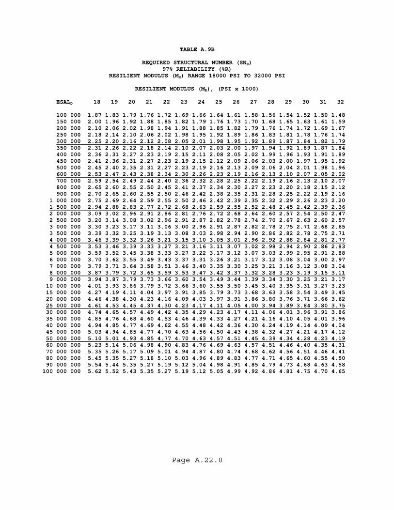
Page A.22.0
TABLE A.9B
REQUIRED STRUCTURAL NUMBER (SNR) 97% RELIABILITY (%R)
RESILIENT MODULUS (MR) RANGE 18000 PSI TO 32000 PSI
RESILIENT MODULUS (MR), (PSI x 1000) ESALD 18 19 20 21 22 23 24 25 26 27 28 29 30 31 32 100 000 1.87 1.83 1.79 1.76 1.72 1.69 1.66 1.64 1.61 1.58 1.56 1.54 1.52 1.50 1.48 150 000 2.00 1.96 1.92 1.88 1.85 1.82 1.79 1.76 1.73 1.70 1.68 1.65 1.63 1.61 1.59 200 000 2.10 2.06 2.02 1.98 1.94 1.91 1.88 1.85 1.82 1.79 1.76 1.74 1.72 1.69 1.67 250 000 2.18 2.14 2.10 2.06 2.02 1.98 1.95 1.92 1.89 1.86 1.83 1.81 1.78 1.76 1.74 300 000 2.25 2.20 2.16 2.12 2.08 2.05 2.01 1.98 1.95 1.92 1.89 1.87 1.84 1.82 1.79 350 000 2.31 2.26 2.22 2.18 2.14 2.10 2.07 2.03 2.00 1.97 1.94 1.92 1.89 1.87 1.84 400 000 2.36 2.31 2.27 2.23 2.19 2.15 2.11 2.08 2.05 2.02 1.99 1.96 1.93 1.91 1.89 450 000 2.41 2.36 2.31 2.27 2.23 2.19 2.15 2.12 2.09 2.06 2.03 2.00 1.97 1.95 1.92 500 000 2.45 2.40 2.35 2.31 2.27 2.23 2.19 2.16 2.13 2.09 2.06 2.04 2.01 1.98 1.96 600 000 2.53 2.47 2.43 2.38 2.34 2.30 2.26 2.23 2.19 2.16 2.13 2.10 2.07 2.05 2.02 700 000 2.59 2.54 2.49 2.44 2.40 2.36 2.32 2.28 2.25 2.22 2.19 2.16 2.13 2.10 2.07 800 000 2.65 2.60 2.55 2.50 2.45 2.41 2.37 2.34 2.30 2.27 2.23 2.20 2.18 2.15 2.12 900 000 2.70 2.65 2.60 2.55 2.50 2.46 2.42 2.38 2.35 2.31 2.28 2.25 2.22 2.19 2.16 1 000 000 2.75 2.69 2.64 2.59 2.55 2.50 2.46 2.42 2.39 2.35 2.32 2.29 2.26 2.23 2.20 1 500 000 2.94 2.88 2.83 2.77 2.72 2.68 2.63 2.59 2.55 2.52 2.48 2.45 2.42 2.39 2.36 2 000 000 3.09 3.02 2.96 2.91 2.86 2.81 2.76 2.72 2.68 2.64 2.60 2.57 2.54 2.50 2.47 2 500 000 3.20 3.14 3.08 3.02 2.96 2.91 2.87 2.82 2.78 2.74 2.70 2.67 2.63 2.60 2.57 3 000 000 3.30 3.23 3.17 3.11 3.06 3.00 2.96 2.91 2.87 2.82 2.78 2.75 2.71 2.68 2.65 3 500 000 3.39 3.32 3.25 3.19 3.13 3.08 3.03 2.98 2.94 2.90 2.86 2.82 2.78 2.75 2.71 4 000 000 3.46 3.39 3.32 3.26 3.21 3.15 3.10 3.05 3.01 2.96 2.92 2.88 2.84 2.81 2.77 4 500 000 3.53 3.46 3.39 3.33 3.27 3.21 3.16 3.11 3.07 3.02 2.98 2.94 2.90 2.86 2.83 5 000 000 3.59 3.52 3.45 3.38 3.33 3.27 3.22 3.17 3.12 3.07 3.03 2.99 2.95 2.91 2.88 6 000 000 3.70 3.62 3.55 3.49 3.43 3.37 3.31 3.26 3.21 3.17 3.12 3.08 3.04 3.00 2.97 7 000 000 3.79 3.71 3.64 3.58 3.51 3.46 3.40 3.35 3.30 3.25 3.21 3.16 3.12 3.08 3.04 8 000 000 3.87 3.79 3.72 3.65 3.59 3.53 3.47 3.42 3.37 3.32 3.28 3.23 3.19 3.15 3.11 9 000 000 3.94 3.87 3.79 3.73 3.66 3.60 3.54 3.49 3.44 3.39 3.34 3.30 3.25 3.21 3.17 10 000 000 4.01 3.93 3.86 3.79 3.72 3.66 3.60 3.55 3.50 3.45 3.40 3.35 3.31 3.27 3.23 15 000 000 4.27 4.19 4.11 4.04 3.97 3.91 3.85 3.79 3.73 3.68 3.63 3.58 3.54 3.49 3.45 20 000 000 4.46 4.38 4.30 4.23 4.16 4.09 4.03 3.97 3.91 3.86 3.80 3.76 3.71 3.66 3.62 25 000 000 4.61 4.53 4.45 4.37 4.30 4.23 4.17 4.11 4.05 4.00 3.94 3.89 3.84 3.80 3.75 30 000 000 4.74 4.65 4.57 4.49 4.42 4.35 4.29 4.23 4.17 4.11 4.06 4.01 3.96 3.91 3.86 35 000 000 4.85 4.76 4.68 4.60 4.53 4.46 4.39 4.33 4.27 4.21 4.16 4.10 4.05 4.01 3.96 40 000 000 4.94 4.85 4.77 4.69 4.62 4.55 4.48 4.42 4.36 4.30 4.24 4.19 4.14 4.09 4.04 45 000 000 5.03 4.94 4.85 4.77 4.70 4.63 4.56 4.50 4.43 4.38 4.32 4.27 4.21 4.17 4.12 50 000 000 5.10 5.01 4.93 4.85 4.77 4.70 4.63 4.57 4.51 4.45 4.39 4.34 4.28 4.23 4.19 60 000 000 5.23 5.14 5.06 4.98 4.90 4.83 4.76 4.69 4.63 4.57 4.51 4.46 4.40 4.35 4.31 70 000 000 5.35 5.26 5.17 5.09 5.01 4.94 4.87 4.80 4.74 4.68 4.62 4.56 4.51 4.46 4.41 80 000 000 5.45 5.35 5.27 5.18 5.10 5.03 4.96 4.89 4.83 4.77 4.71 4.65 4.60 4.55 4.50 90 000 000 5.54 5.44 5.35 5.27 5.19 5.12 5.04 4.98 4.91 4.85 4.79 4.73 4.68 4.63 4.58 100 000 000 5.62 5.52 5.43 5.35 5.27 5.19 5.12 5.05 4.99 4.92 4.86 4.81 4.75 4.70 4.65
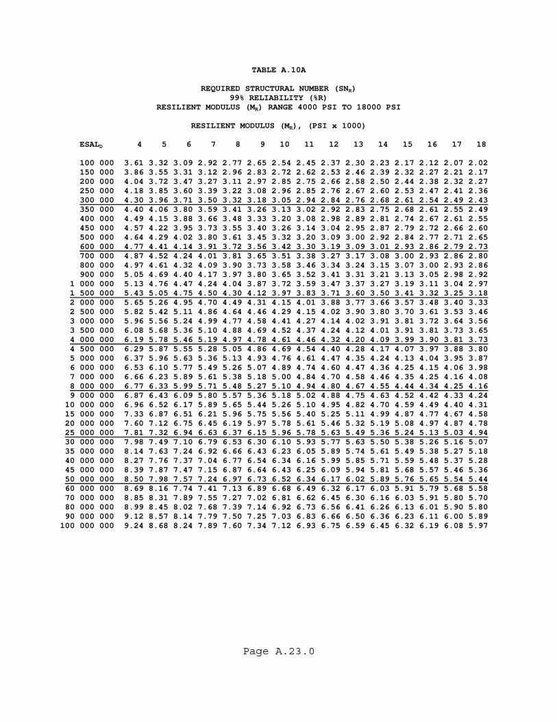
Page A.23.0
TABLE A.10A
REQUIRED STRUCTURAL NUMBER (SNR) 99% RELIABILITY (%R)
RESILIENT MODULUS (MR) RANGE 4000 PSI TO 18000 PSI
RESILIENT MODULUS (MR), (PSI x 1000)
ESALD 4 5 6 7 8 9 10 11 12 13 14 15 16 17 18 100 000 3.61 3.32 3.09 2.92 2.77 2.65 2.54 2.45 2.37 2.30 2.23 2.17 2.12 2.07 2.02 150 000 3.86 3.55 3.31 3.12 2.96 2.83 2.72 2.62 2.53 2.46 2.39 2.32 2.27 2.21 2.17 200 000 4.04 3.72 3.47 3.27 3.11 2.97 2.85 2.75 2.66 2.58 2.50 2.44 2.38 2.32 2.27 250 000 4.18 3.85 3.60 3.39 3.22 3.08 2.96 2.85 2.76 2.67 2.60 2.53 2.47 2.41 2.36 300 000 4.30 3.96 3.71 3.50 3.32 3.18 3.05 2.94 2.84 2.76 2.68 2.61 2.54 2.49 2.43 350 000 4.40 4.06 3.80 3.59 3.41 3.26 3.13 3.02 2.92 2.83 2.75 2.68 2.61 2.55 2.49 400 000 4.49 4.15 3.88 3.66 3.48 3.33 3.20 3.08 2.98 2.89 2.81 2.74 2.67 2.61 2.55 450 000 4.57 4.22 3.95 3.73 3.55 3.40 3.26 3.14 3.04 2.95 2.87 2.79 2.72 2.66 2.60 500 000 4.64 4.29 4.02 3.80 3.61 3.45 3.32 3.20 3.09 3.00 2.92 2.84 2.77 2.71 2.65 600 000 4.77 4.41 4.14 3.91 3.72 3.56 3.42 3.30 3.19 3.09 3.01 2.93 2.86 2.79 2.73 700 000 4.87 4.52 4.24 4.01 3.81 3.65 3.51 3.38 3.27 3.17 3.08 3.00 2.93 2.86 2.80 800 000 4.97 4.61 4.32 4.09 3.90 3.73 3.58 3.46 3.34 3.24 3.15 3.07 3.00 2.93 2.86 900 000 5.05 4.69 4.40 4.17 3.97 3.80 3.65 3.52 3.41 3.31 3.21 3.13 3.05 2.98 2.92 1 000 000 5.13 4.76 4.47 4.24 4.04 3.87 3.72 3.59 3.47 3.37 3.27 3.19 3.11 3.04 2.97 1 500 000 5.43 5.05 4.75 4.50 4.30 4.12 3.97 3.83 3.71 3.60 3.50 3.41 3.32 3.25 3.18 2 000 000 5.65 5.26 4.95 4.70 4.49 4.31 4.15 4.01 3.88 3.77 3.66 3.57 3.48 3.40 3.33 2 500 000 5.82 5.42 5.11 4.86 4.64 4.46 4.29 4.15 4.02 3.90 3.80 3.70 3.61 3.53 3.46 3 000 000 5.96 5.56 5.24 4.99 4.77 4.58 4.41 4.27 4.14 4.02 3.91 3.81 3.72 3.64 3.56 3 500 000 6.08 5.68 5.36 5.10 4.88 4.69 4.52 4.37 4.24 4.12 4.01 3.91 3.81 3.73 3.65 4 000 000 6.19 5.78 5.46 5.19 4.97 4.78 4.61 4.46 4.32 4.20 4.09 3.99 3.90 3.81 3.73 4 500 000 6.29 5.87 5.55 5.28 5.05 4.86 4.69 4.54 4.40 4.28 4.17 4.07 3.97 3.88 3.80 5 000 000 6.37 5.96 5.63 5.36 5.13 4.93 4.76 4.61 4.47 4.35 4.24 4.13 4.04 3.95 3.87 6 000 000 6.53 6.10 5.77 5.49 5.26 5.07 4.89 4.74 4.60 4.47 4.36 4.25 4.15 4.06 3.98 7 000 000 6.66 6.23 5.89 5.61 5.38 5.18 5.00 4.84 4.70 4.58 4.46 4.35 4.25 4.16 4.08 8 000 000 6.77 6.33 5.99 5.71 5.48 5.27 5.10 4.94 4.80 4.67 4.55 4.44 4.34 4.25 4.16 9 000 000 6.87 6.43 6.09 5.80 5.57 5.36 5.18 5.02 4.88 4.75 4.63 4.52 4.42 4.33 4.24 10 000 000 6.96 6.52 6.17 5.89 5.65 5.44 5.26 5.10 4.95 4.82 4.70 4.59 4.49 4.40 4.31 15 000 000 7.33 6.87 6.51 6.21 5.96 5.75 5.56 5.40 5.25 5.11 4.99 4.87 4.77 4.67 4.58 20 000 000 7.60 7.12 6.75 6.45 6.19 5.97 5.78 5.61 5.46 5.32 5.19 5.08 4.97 4.87 4.78 25 000 000 7.81 7.32 6.94 6.63 6.37 6.15 5.96 5.78 5.63 5.49 5.36 5.24 5.13 5.03 4.94 30 000 000 7.98 7.49 7.10 6.79 6.53 6.30 6.10 5.93 5.77 5.63 5.50 5.38 5.26 5.16 5.07 35 000 000 8.14 7.63 7.24 6.92 6.66 6.43 6.23 6.05 5.89 5.74 5.61 5.49 5.38 5.27 5.18 40 000 000 8.27 7.76 7.37 7.04 6.77 6.54 6.34 6.16 5.99 5.85 5.71 5.59 5.48 5.37 5.28 45 000 000 8.39 7.87 7.47 7.15 6.87 6.64 6.43 6.25 6.09 5.94 5.81 5.68 5.57 5.46 5.36 50 000 000 8.50 7.98 7.57 7.24 6.97 6.73 6.52 6.34 6.17 6.02 5.89 5.76 5.65 5.54 5.44 60 000 000 8.69 8.16 7.74 7.41 7.13 6.89 6.68 6.49 6.32 6.17 6.03 5.91 5.79 5.68 5.58 70 000 000 8.85 8.31 7.89 7.55 7.27 7.02 6.81 6.62 6.45 6.30 6.16 6.03 5.91 5.80 5.70 80 000 000 8.99 8.45 8.02 7.68 7.39 7.14 6.92 6.73 6.56 6.41 6.26 6.13 6.01 5.90 5.80 90 000 000 9.12 8.57 8.14 7.79 7.50 7.25 7.03 6.83 6.66 6.50 6.36 6.23 6.11 6.00 5.89 100 000 000 9.24 8.68 8.24 7.89 7.60 7.34 7.12 6.93 6.75 6.59 6.45 6.32 6.19 6.08 5.97
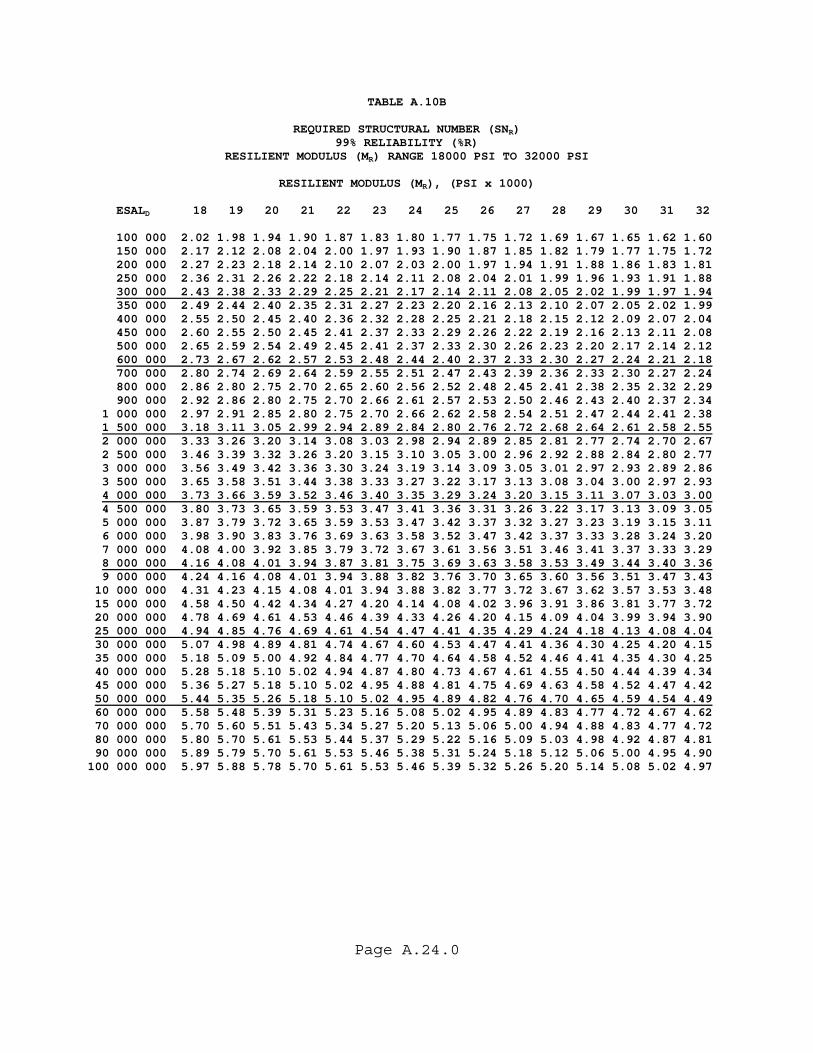
Page A.24.0
TABLE A.10B
REQUIRED STRUCTURAL NUMBER (SNR) 99% RELIABILITY (%R)
RESILIENT MODULUS (MR) RANGE 18000 PSI TO 32000 PSI
RESILIENT MODULUS (MR), (PSI x 1000) ESALD 18 19 20 21 22 23 24 25 26 27 28 29 30 31 32 100 000 2.02 1.98 1.94 1.90 1.87 1.83 1.80 1.77 1.75 1.72 1.69 1.67 1.65 1.62 1.60 150 000 2.17 2.12 2.08 2.04 2.00 1.97 1.93 1.90 1.87 1.85 1.82 1.79 1.77 1.75 1.72 200 000 2.27 2.23 2.18 2.14 2.10 2.07 2.03 2.00 1.97 1.94 1.91 1.88 1.86 1.83 1.81 250 000 2.36 2.31 2.26 2.22 2.18 2.14 2.11 2.08 2.04 2.01 1.99 1.96 1.93 1.91 1.88 300 000 2.43 2.38 2.33 2.29 2.25 2.21 2.17 2.14 2.11 2.08 2.05 2.02 1.99 1.97 1.94 350 000 2.49 2.44 2.40 2.35 2.31 2.27 2.23 2.20 2.16 2.13 2.10 2.07 2.05 2.02 1.99 400 000 2.55 2.50 2.45 2.40 2.36 2.32 2.28 2.25 2.21 2.18 2.15 2.12 2.09 2.07 2.04 450 000 2.60 2.55 2.50 2.45 2.41 2.37 2.33 2.29 2.26 2.22 2.19 2.16 2.13 2.11 2.08 500 000 2.65 2.59 2.54 2.49 2.45 2.41 2.37 2.33 2.30 2.26 2.23 2.20 2.17 2.14 2.12 600 000 2.73 2.67 2.62 2.57 2.53 2.48 2.44 2.40 2.37 2.33 2.30 2.27 2.24 2.21 2.18 700 000 2.80 2.74 2.69 2.64 2.59 2.55 2.51 2.47 2.43 2.39 2.36 2.33 2.30 2.27 2.24 800 000 2.86 2.80 2.75 2.70 2.65 2.60 2.56 2.52 2.48 2.45 2.41 2.38 2.35 2.32 2.29 900 000 2.92 2.86 2.80 2.75 2.70 2.66 2.61 2.57 2.53 2.50 2.46 2.43 2.40 2.37 2.34 1 000 000 2.97 2.91 2.85 2.80 2.75 2.70 2.66 2.62 2.58 2.54 2.51 2.47 2.44 2.41 2.38 1 500 000 3.18 3.11 3.05 2.99 2.94 2.89 2.84 2.80 2.76 2.72 2.68 2.64 2.61 2.58 2.55 2 000 000 3.33 3.26 3.20 3.14 3.08 3.03 2.98 2.94 2.89 2.85 2.81 2.77 2.74 2.70 2.67 2 500 000 3.46 3.39 3.32 3.26 3.20 3.15 3.10 3.05 3.00 2.96 2.92 2.88 2.84 2.80 2.77 3 000 000 3.56 3.49 3.42 3.36 3.30 3.24 3.19 3.14 3.09 3.05 3.01 2.97 2.93 2.89 2.86 3 500 000 3.65 3.58 3.51 3.44 3.38 3.33 3.27 3.22 3.17 3.13 3.08 3.04 3.00 2.97 2.93 4 000 000 3.73 3.66 3.59 3.52 3.46 3.40 3.35 3.29 3.24 3.20 3.15 3.11 3.07 3.03 3.00 4 500 000 3.80 3.73 3.65 3.59 3.53 3.47 3.41 3.36 3.31 3.26 3.22 3.17 3.13 3.09 3.05 5 000 000 3.87 3.79 3.72 3.65 3.59 3.53 3.47 3.42 3.37 3.32 3.27 3.23 3.19 3.15 3.11 6 000 000 3.98 3.90 3.83 3.76 3.69 3.63 3.58 3.52 3.47 3.42 3.37 3.33 3.28 3.24 3.20 7 000 000 4.08 4.00 3.92 3.85 3.79 3.72 3.67 3.61 3.56 3.51 3.46 3.41 3.37 3.33 3.29 8 000 000 4.16 4.08 4.01 3.94 3.87 3.81 3.75 3.69 3.63 3.58 3.53 3.49 3.44 3.40 3.36 9 000 000 4.24 4.16 4.08 4.01 3.94 3.88 3.82 3.76 3.70 3.65 3.60 3.56 3.51 3.47 3.43 10 000 000 4.31 4.23 4.15 4.08 4.01 3.94 3.88 3.82 3.77 3.72 3.67 3.62 3.57 3.53 3.48 15 000 000 4.58 4.50 4.42 4.34 4.27 4.20 4.14 4.08 4.02 3.96 3.91 3.86 3.81 3.77 3.72 20 000 000 4.78 4.69 4.61 4.53 4.46 4.39 4.33 4.26 4.20 4.15 4.09 4.04 3.99 3.94 3.90 25 000 000 4.94 4.85 4.76 4.69 4.61 4.54 4.47 4.41 4.35 4.29 4.24 4.18 4.13 4.08 4.04 30 000 000 5.07 4.98 4.89 4.81 4.74 4.67 4.60 4.53 4.47 4.41 4.36 4.30 4.25 4.20 4.15 35 000 000 5.18 5.09 5.00 4.92 4.84 4.77 4.70 4.64 4.58 4.52 4.46 4.41 4.35 4.30 4.25 40 000 000 5.28 5.18 5.10 5.02 4.94 4.87 4.80 4.73 4.67 4.61 4.55 4.50 4.44 4.39 4.34 45 000 000 5.36 5.27 5.18 5.10 5.02 4.95 4.88 4.81 4.75 4.69 4.63 4.58 4.52 4.47 4.42 50 000 000 5.44 5.35 5.26 5.18 5.10 5.02 4.95 4.89 4.82 4.76 4.70 4.65 4.59 4.54 4.49 60 000 000 5.58 5.48 5.39 5.31 5.23 5.16 5.08 5.02 4.95 4.89 4.83 4.77 4.72 4.67 4.62 70 000 000 5.70 5.60 5.51 5.43 5.34 5.27 5.20 5.13 5.06 5.00 4.94 4.88 4.83 4.77 4.72 80 000 000 5.80 5.70 5.61 5.53 5.44 5.37 5.29 5.22 5.16 5.09 5.03 4.98 4.92 4.87 4.81 90 000 000 5.89 5.79 5.70 5.61 5.53 5.46 5.38 5.31 5.24 5.18 5.12 5.06 5.00 4.95 4.90 100 000 000 5.97 5.88 5.78 5.70 5.61 5.53 5.46 5.39 5.32 5.26 5.20 5.14 5.08 5.02 4.97
Page A.25.0
METRIC TABLES
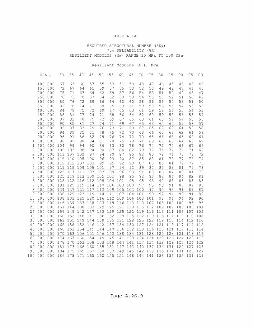
Page A.26.0
TABLE A.1A REQUIRED STRUCTURAL NUMBER (SNR) 75% RELIABILITY (%R) RESILIENT MODULUS (MR) RANGE 30 MPa TO 100 MPa Resilient Modulus (MR), MPa ESALD 30 35 40 45 50 55 60 65 70 75 80 85 90 95 100 100 000 67 63 60 57 55 53 51 50 48 47 46 45 43 43 42 150 000 72 67 64 61 59 57 55 53 52 50 49 48 47 46 45 200 000 75 71 67 64 62 59 57 56 54 53 51 50 49 48 47 250 000 78 73 70 67 64 62 60 58 56 55 53 52 51 50 49 300 000 80 76 72 69 66 64 62 60 58 56 55 54 53 51 50 350 000 82 78 74 71 68 65 63 61 59 58 56 55 54 53 52 400 000 84 79 75 72 69 67 65 63 61 59 58 56 55 54 53 450 000 86 81 77 74 71 68 66 64 62 60 59 58 56 55 54 500 000 87 82 78 75 72 69 67 65 63 61 60 59 57 56 55 600 000 90 85 81 77 74 71 69 67 65 63 62 60 59 58 57 700 000 92 87 83 79 76 73 71 69 67 65 63 62 61 59 58 800 000 94 89 85 81 78 75 72 70 68 66 65 63 62 61 59 900 000 96 91 86 82 79 76 74 72 70 68 66 65 63 62 61 1 000 000 98 92 88 84 81 78 75 73 71 69 67 66 64 63 62 1 500 000 104 99 94 90 86 83 80 78 76 74 72 70 69 67 66 2 000 000 109 103 98 94 90 87 84 82 79 77 75 74 72 71 69 2 500 000 113 107 102 97 94 90 87 85 82 80 78 76 75 73 72 3 000 000 116 110 105 100 96 93 90 87 85 83 81 79 77 76 74 3 500 000 119 112 107 103 99 95 92 90 87 85 83 81 79 77 76 4 000 000 121 115 109 105 101 97 94 92 89 87 85 83 81 79 78 4 500 000 123 117 111 107 103 99 96 93 91 88 86 84 82 81 79 5 000 000 125 119 113 109 105 101 98 95 92 90 88 86 84 82 81 6 000 000 128 122 116 112 108 104 101 98 95 93 90 88 86 85 83 7 000 000 131 125 119 114 110 106 103 100 97 95 93 91 89 87 85 8 000 000 134 127 121 117 112 109 105 102 100 97 95 93 91 89 87 9 000 000 136 129 123 119 114 111 107 104 101 99 97 94 92 91 89 10 000 000 138 131 125 120 116 112 109 106 103 101 98 96 94 92 90 15 000 000 146 139 133 128 123 119 116 113 110 107 105 102 100 98 96 20 000 000 151 144 138 133 129 125 121 118 115 112 109 107 105 103 101 25 000 000 156 149 142 137 133 129 125 122 119 116 113 111 109 107 105 30 000 000 160 152 146 141 136 132 128 125 122 119 116 114 112 110 108 35 000 000 163 155 149 144 139 135 131 128 125 122 119 117 114 112 110 40 000 000 166 158 152 146 142 137 134 130 127 124 121 119 117 114 112 45 000 000 168 161 154 149 144 140 136 132 129 126 123 121 119 116 114 50 000 000 170 163 156 151 146 142 138 134 131 128 125 123 121 118 116 60 000 000 174 167 160 154 149 145 141 138 134 131 129 126 124 122 119 70 000 000 178 170 163 158 153 148 144 141 137 134 132 129 127 124 122 80 000 000 181 173 166 160 155 151 147 143 140 137 134 131 129 127 125 90 000 000 184 175 169 163 158 153 149 145 142 139 136 134 131 129 127 100 000 000 186 178 171 165 160 155 151 148 144 141 138 136 133 131 129
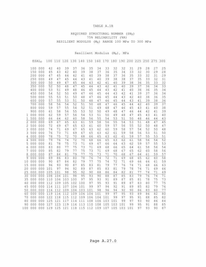
Page A.27.0
TABLE A.1B REQUIRED STRUCTURAL NUMBER (SNR) 75% RELIABILITY (%R) RESILIENT MODULUS (MR) RANGE 100 MPa TO 300 MPa Resilient Modulus (MR), MPa ESALD 100 110 120 130 140 150 160 170 180 190 200 225 250 275 300 100 000 42 40 39 37 36 35 34 33 32 32 31 29 28 27 25 150 000 45 43 42 40 39 38 37 36 35 34 33 32 30 29 28 200 000 47 45 44 42 41 40 39 38 37 36 35 33 32 31 29 250 000 49 47 45 44 43 41 40 39 38 38 37 35 33 32 31 300 000 50 49 47 45 44 43 42 41 40 39 38 36 35 33 32 350 000 52 50 48 47 45 44 43 42 41 40 39 37 36 34 33 400 000 53 51 49 48 46 45 44 43 42 41 40 38 36 35 34 450 000 54 52 50 49 47 46 45 44 43 42 41 39 37 36 34 500 000 55 53 51 50 48 47 46 45 44 43 42 40 38 36 35 600 000 57 55 53 51 50 48 47 46 45 44 43 41 39 38 36 700 000 58 56 54 52 51 50 48 47 46 45 44 42 40 39 37 800 000 59 57 55 54 52 51 49 48 47 46 45 43 41 40 38 900 000 61 58 56 55 53 52 50 49 48 47 46 44 42 41 39 1 000 000 62 59 57 56 54 53 51 50 49 48 47 45 43 41 40 1 500 000 66 64 62 60 58 56 55 54 53 51 50 48 46 44 43 2 000 000 69 67 65 63 61 59 58 56 55 54 53 51 48 47 45 2 500 000 72 69 67 65 63 61 60 59 57 56 55 52 50 48 47 3 000 000 74 71 69 67 65 63 62 60 59 58 57 54 52 50 48 3 500 000 76 73 71 69 67 65 63 62 61 59 58 56 53 51 50 4 000 000 78 75 72 70 68 66 65 63 62 61 59 57 55 53 51 4 500 000 79 76 74 72 70 68 66 65 63 62 61 58 56 54 52 5 000 000 81 78 75 73 71 69 67 66 64 63 62 59 57 55 53 6 000 000 83 80 77 75 73 71 69 68 66 65 64 61 58 56 54 7 000 000 85 82 79 77 75 73 71 69 68 67 65 62 60 58 56 8 000 000 87 84 81 79 77 75 73 71 70 68 67 64 61 59 57 9 000 000 89 86 83 80 78 76 74 72 71 69 68 65 62 60 58 10 000 000 90 87 84 82 79 77 75 74 72 71 69 66 64 61 59 15 000 000 96 93 90 87 85 83 81 79 77 76 74 71 68 66 63 20 000 000 101 97 94 92 89 87 85 83 81 79 78 74 71 69 66 25 000 000 105 101 98 95 92 90 88 86 84 82 81 77 74 71 69 30 000 000 108 104 101 98 95 93 90 88 87 85 83 79 76 74 71 35 000 000 110 106 103 100 97 95 93 91 89 87 85 81 78 75 73 40 000 000 112 109 105 102 100 97 95 93 91 89 87 83 80 77 75 45 000 000 114 111 107 104 101 99 97 94 92 91 89 85 82 79 76 50 000 000 116 112 109 106 103 101 98 96 94 92 90 86 83 80 77 60 000 000 119 116 112 109 106 104 101 99 97 95 93 89 86 82 80 70 000 000 122 118 115 112 109 106 104 101 99 97 95 91 88 85 82 80 000 000 125 121 117 114 111 108 106 103 101 99 97 93 90 86 84 90 000 000 127 123 119 116 113 110 108 105 103 101 99 95 91 88 85 100 000 000 129 125 121 118 115 112 109 107 105 103 101 97 93 90 87
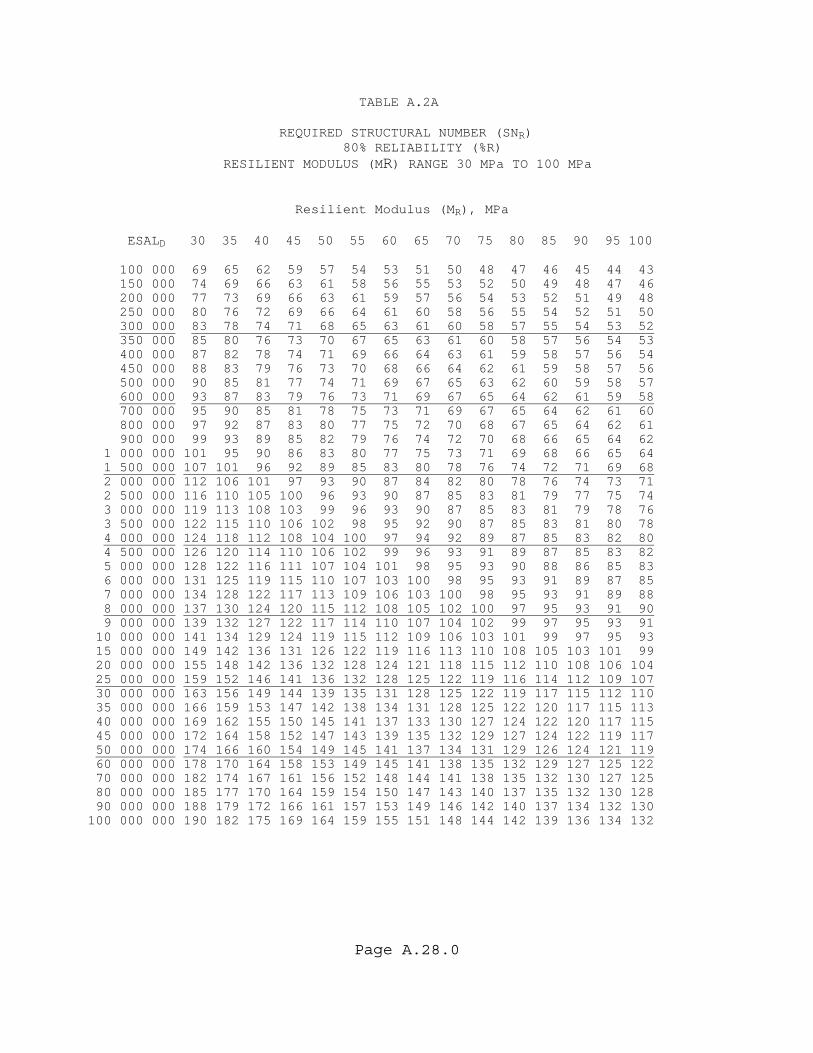
Page A.28.0
TABLE A.2A REQUIRED STRUCTURAL NUMBER (SNR) 80% RELIABILITY (%R) RESILIENT MODULUS (MR) RANGE 30 MPa TO 100 MPa Resilient Modulus (MR), MPa ESALD 30 35 40 45 50 55 60 65 70 75 80 85 90 95 100 100 000 69 65 62 59 57 54 53 51 50 48 47 46 45 44 43 150 000 74 69 66 63 61 58 56 55 53 52 50 49 48 47 46 200 000 77 73 69 66 63 61 59 57 56 54 53 52 51 49 48 250 000 80 76 72 69 66 64 61 60 58 56 55 54 52 51 50 300 000 83 78 74 71 68 65 63 61 60 58 57 55 54 53 52 350 000 85 80 76 73 70 67 65 63 61 60 58 57 56 54 53 400 000 87 82 78 74 71 69 66 64 63 61 59 58 57 56 54 450 000 88 83 79 76 73 70 68 66 64 62 61 59 58 57 56 500 000 90 85 81 77 74 71 69 67 65 63 62 60 59 58 57 600 000 93 87 83 79 76 73 71 69 67 65 64 62 61 59 58 700 000 95 90 85 81 78 75 73 71 69 67 65 64 62 61 60 800 000 97 92 87 83 80 77 75 72 70 68 67 65 64 62 61 900 000 99 93 89 85 82 79 76 74 72 70 68 66 65 64 62 1 000 000 101 95 90 86 83 80 77 75 73 71 69 68 66 65 64 1 500 000 107 101 96 92 89 85 83 80 78 76 74 72 71 69 68 2 000 000 112 106 101 97 93 90 87 84 82 80 78 76 74 73 71 2 500 000 116 110 105 100 96 93 90 87 85 83 81 79 77 75 74 3 000 000 119 113 108 103 99 96 93 90 87 85 83 81 79 78 76 3 500 000 122 115 110 106 102 98 95 92 90 87 85 83 81 80 78 4 000 000 124 118 112 108 104 100 97 94 92 89 87 85 83 82 80 4 500 000 126 120 114 110 106 102 99 96 93 91 89 87 85 83 82 5 000 000 128 122 116 111 107 104 101 98 95 93 90 88 86 85 83 6 000 000 131 125 119 115 110 107 103 100 98 95 93 91 89 87 85 7 000 000 134 128 122 117 113 109 106 103 100 98 95 93 91 89 88 8 000 000 137 130 124 120 115 112 108 105 102 100 97 95 93 91 90 9 000 000 139 132 127 122 117 114 110 107 104 102 99 97 95 93 91 10 000 000 141 134 129 124 119 115 112 109 106 103 101 99 97 95 93 15 000 000 149 142 136 131 126 122 119 116 113 110 108 105 103 101 99 20 000 000 155 148 142 136 132 128 124 121 118 115 112 110 108 106 104 25 000 000 159 152 146 141 136 132 128 125 122 119 116 114 112 109 107 30 000 000 163 156 149 144 139 135 131 128 125 122 119 117 115 112 110 35 000 000 166 159 153 147 142 138 134 131 128 125 122 120 117 115 113 40 000 000 169 162 155 150 145 141 137 133 130 127 124 122 120 117 115 45 000 000 172 164 158 152 147 143 139 135 132 129 127 124 122 119 117 50 000 000 174 166 160 154 149 145 141 137 134 131 129 126 124 121 119 60 000 000 178 170 164 158 153 149 145 141 138 135 132 129 127 125 122 70 000 000 182 174 167 161 156 152 148 144 141 138 135 132 130 127 125 80 000 000 185 177 170 164 159 154 150 147 143 140 137 135 132 130 128 90 000 000 188 179 172 166 161 157 153 149 146 142 140 137 134 132 130 100 000 000 190 182 175 169 164 159 155 151 148 144 142 139 136 134 132
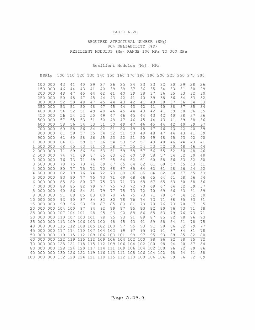
Page A.29.0
TABLE A.2B REQUIRED STRUCTURAL NUMBER (SNR) 80% RELIABILITY (%R) RESILIENT MODULUS (MR) RANGE 100 MPa TO 300 MPa Resilient Modulus (MR), MPa ESALD 100 110 120 130 140 150 160 170 180 190 200 225 250 275 300 100 000 43 41 40 39 37 36 35 34 33 33 32 30 29 28 26 150 000 46 44 43 41 40 39 38 37 36 35 34 33 31 30 29 200 000 48 47 45 44 42 41 40 39 38 37 36 35 33 32 30 250 000 50 48 47 45 44 43 42 41 40 39 38 36 34 33 32 300 000 52 50 48 47 45 44 43 42 41 40 39 37 36 34 33 350 000 53 51 50 48 47 45 44 43 42 41 40 38 37 35 34 400 000 54 52 51 49 48 46 45 44 43 42 41 39 38 36 35 450 000 56 54 52 50 49 47 46 45 44 43 42 40 38 37 36 500 000 57 55 53 51 50 48 47 46 45 44 43 41 39 38 36 600 000 58 56 54 53 51 50 49 47 46 45 44 42 40 39 37 700 000 60 58 56 54 52 51 50 49 48 47 46 43 42 40 39 800 000 61 59 57 55 54 52 51 50 49 48 47 44 43 41 39 900 000 62 60 58 56 55 53 52 51 50 49 48 45 43 42 40 1 000 000 64 61 59 57 56 54 53 52 51 49 48 46 44 43 41 1 500 000 68 65 63 61 60 58 57 55 54 53 52 50 48 46 44 2 000 000 71 69 66 64 63 61 59 58 57 56 55 52 50 48 46 2 500 000 74 71 69 67 65 63 62 60 59 58 57 54 52 50 48 3 000 000 76 73 71 69 67 65 64 62 61 60 58 56 53 52 50 3 500 000 78 75 73 71 69 67 65 64 62 61 60 57 55 53 51 4 000 000 80 77 75 72 70 68 67 65 64 62 61 58 56 54 52 4 500 000 82 79 76 74 72 70 68 66 65 64 62 60 57 55 53 5 000 000 83 80 77 75 73 71 69 68 66 65 64 61 58 56 54 6 000 000 85 82 80 77 75 73 71 70 68 67 65 63 60 58 56 7 000 000 88 85 82 79 77 75 73 72 70 69 67 64 62 59 57 8 000 000 90 86 84 81 79 77 75 73 72 70 69 66 63 61 59 9 000 000 91 88 85 83 80 78 76 75 73 71 70 67 64 62 60 10 000 000 93 90 87 84 82 80 78 76 74 73 71 68 65 63 61 15 000 000 99 96 93 90 87 85 83 81 79 78 76 73 70 67 65 20 000 000 104 100 97 94 92 89 87 85 83 82 80 76 73 71 68 25 000 000 107 104 101 98 95 93 90 88 86 85 83 79 76 73 71 30 000 000 110 107 103 101 98 95 93 91 89 87 85 82 78 76 73 35 000 000 113 109 106 103 100 98 95 93 91 89 88 84 81 78 75 40 000 000 115 112 108 105 102 100 97 95 93 91 90 86 82 79 77 45 000 000 117 114 110 107 104 102 99 97 95 93 91 87 84 81 78 50 000 000 119 115 112 109 106 103 101 99 97 95 93 89 85 82 80 60 000 000 122 119 115 112 109 106 104 102 100 98 96 92 88 85 82 70 000 000 125 121 118 115 112 109 106 104 102 100 98 94 90 87 84 80 000 000 128 124 120 117 114 111 109 106 104 102 100 96 92 89 86 90 000 000 130 126 122 119 116 113 111 108 106 104 102 98 94 91 88 100 000 000 132 128 124 121 118 115 112 110 108 106 104 99 96 92 89
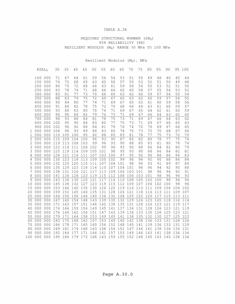
Page A.30.0
TABLE A.3A REQUIRED STRUCTURAL NUMBER (SNR) 85% RELIABILITY (%R) RESILIENT MODULUS (MR) RANGE 30 MPa TO 100 MPa Resilient Modulus (MR), MPa ESALD 30 35 40 45 50 55 60 65 70 75 80 85 90 95 100 100 000 71 67 64 61 59 56 54 53 51 50 49 48 46 45 44 150 000 76 72 68 65 63 60 58 57 55 53 52 51 50 49 48 200 000 80 75 72 68 66 63 61 59 58 56 55 53 52 51 50 250 000 83 78 74 71 68 66 64 62 60 58 57 55 54 53 52 300 000 85 81 77 73 70 68 65 63 62 60 59 57 56 55 54 350 000 88 83 79 75 72 69 67 65 63 62 60 59 57 56 55 400 000 90 84 80 77 74 71 69 67 65 63 61 60 59 58 56 450 000 91 86 82 78 75 72 70 68 66 64 63 61 60 59 57 500 000 93 88 83 80 76 74 71 69 67 65 64 62 61 60 59 600 000 96 90 86 82 79 76 73 71 69 67 66 64 63 62 60 700 000 98 93 88 84 81 78 75 73 71 69 67 66 64 63 62 800 000 100 95 90 86 83 80 77 75 73 71 69 67 66 65 63 900 000 102 96 92 88 84 81 79 76 74 72 70 69 67 66 65 1 000 000 104 98 93 89 86 83 80 78 75 73 72 70 68 67 66 1 500 000 110 105 100 95 92 88 85 83 81 78 77 75 73 72 70 2 000 000 115 109 104 100 96 93 90 87 85 82 80 78 77 75 74 2 500 000 119 113 108 103 99 96 93 90 88 85 83 81 80 78 76 3 000 000 122 116 111 106 102 99 96 93 90 88 86 84 82 80 79 3 500 000 125 119 114 109 105 101 98 95 93 90 88 86 84 82 81 4 000 000 128 121 116 111 107 103 100 97 95 92 90 88 86 84 83 4 500 000 130 123 118 113 109 105 102 99 96 94 92 90 88 86 84 5 000 000 132 125 120 115 111 107 104 101 98 96 93 91 89 87 86 6 000 000 135 129 123 118 114 110 107 104 101 98 96 94 92 90 88 7 000 000 138 131 126 121 117 113 109 106 103 101 98 96 94 92 91 8 000 000 141 134 128 123 119 115 112 108 106 103 101 98 96 94 93 9 000 000 143 136 130 125 121 117 114 110 108 105 102 100 98 96 94 10 000 000 145 138 132 127 123 119 115 112 109 107 104 102 100 98 96 15 000 000 153 146 140 135 130 126 122 119 116 113 111 109 106 104 102 20 000 000 159 152 145 140 135 131 128 124 121 118 116 113 111 109 107 25 000 000 164 156 150 144 140 136 132 128 125 122 120 117 115 113 111 30 000 000 167 160 154 148 143 139 135 132 129 126 123 120 118 116 114 35 000 000 171 163 157 151 146 142 138 135 131 128 126 123 121 119 117 40 000 000 174 166 159 154 149 145 141 137 134 131 128 126 123 121 119 45 000 000 176 168 162 156 151 147 143 139 136 133 130 128 125 123 121 50 000 000 179 171 164 158 153 149 145 141 138 135 132 130 127 125 123 60 000 000 183 175 168 162 157 153 149 145 142 138 136 133 131 128 126 70 000 000 186 178 171 165 160 156 152 148 145 141 139 136 133 131 129 80 000 000 189 181 174 168 163 158 154 151 147 144 141 138 136 134 131 90 000 000 192 184 177 171 166 161 157 153 149 146 143 141 138 136 134 100 000 000 195 186 179 173 168 163 159 155 152 148 145 143 140 138 136
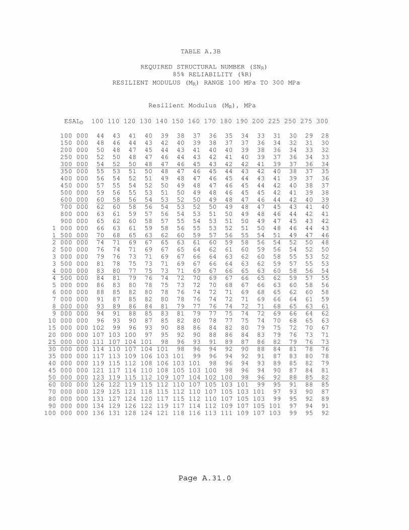
Page A.31.0
TABLE A.3B REQUIRED STRUCTURAL NUMBER (SNR) 85% RELIABILITY (%R) RESILIENT MODULUS (MR) RANGE 100 MPa TO 300 MPa Resilient Modulus (MR), MPa ESALD 100 110 120 130 140 150 160 170 180 190 200 225 250 275 300 100 000 44 43 41 40 39 38 37 36 35 34 33 31 30 29 28 150 000 48 46 44 43 42 40 39 38 37 37 36 34 32 31 30 200 000 50 48 47 45 44 43 41 40 40 39 38 36 34 33 32 250 000 52 50 48 47 46 44 43 42 41 40 39 37 36 34 33 300 000 54 52 50 48 47 46 45 43 42 42 41 39 37 36 34 350 000 55 53 51 50 48 47 46 45 44 43 42 40 38 37 35 400 000 56 54 52 51 49 48 47 46 45 44 43 41 39 37 36 450 000 57 55 54 52 50 49 48 47 46 45 44 42 40 38 37 500 000 59 56 55 53 51 50 49 48 46 45 45 42 41 39 38 600 000 60 58 56 54 53 52 50 49 48 47 46 44 42 40 39 700 000 62 60 58 56 54 53 52 50 49 48 47 45 43 41 40 800 000 63 61 59 57 56 54 53 51 50 49 48 46 44 42 41 900 000 65 62 60 58 57 55 54 53 51 50 49 47 45 43 42 1 000 000 66 63 61 59 58 56 55 53 52 51 50 48 46 44 43 1 500 000 70 68 65 63 62 60 59 57 56 55 54 51 49 47 46 2 000 000 74 71 69 67 65 63 61 60 59 58 56 54 52 50 48 2 500 000 76 74 71 69 67 65 64 62 61 60 59 56 54 52 50 3 000 000 79 76 73 71 69 67 66 64 63 62 60 58 55 53 52 3 500 000 81 78 75 73 71 69 67 66 64 63 62 59 57 55 53 4 000 000 83 80 77 75 73 71 69 67 66 65 63 60 58 56 54 4 500 000 84 81 79 76 74 72 70 69 67 66 65 62 59 57 55 5 000 000 86 83 80 78 75 73 72 70 68 67 66 63 60 58 56 6 000 000 88 85 82 80 78 76 74 72 71 69 68 65 62 60 58 7 000 000 91 87 85 82 80 78 76 74 72 71 69 66 64 61 59 8 000 000 93 89 86 84 81 79 77 76 74 72 71 68 65 63 61 9 000 000 94 91 88 85 83 81 79 77 75 74 72 69 66 64 62 10 000 000 96 93 90 87 85 82 80 78 77 75 74 70 68 65 63 15 000 000 102 99 96 93 90 88 86 84 82 80 79 75 72 70 67 20 000 000 107 103 100 97 95 92 90 88 86 84 83 79 76 73 71 25 000 000 111 107 104 101 98 96 93 91 89 87 86 82 79 76 73 30 000 000 114 110 107 104 101 98 96 94 92 90 88 84 81 78 76 35 000 000 117 113 109 106 103 101 99 96 94 92 91 87 83 80 78 40 000 000 119 115 112 108 106 103 101 98 96 94 93 89 85 82 79 45 000 000 121 117 114 110 108 105 103 100 98 96 94 90 87 84 81 50 000 000 123 119 115 112 109 107 104 102 100 98 96 92 88 85 82 60 000 000 126 122 119 115 112 110 107 105 103 101 99 95 91 88 85 70 000 000 129 125 121 118 115 112 110 107 105 103 101 97 93 90 87 80 000 000 131 127 124 120 117 115 112 110 107 105 103 99 95 92 89 90 000 000 134 129 126 122 119 117 114 112 109 107 105 101 97 94 91 100 000 000 136 131 128 124 121 118 116 113 111 109 107 103 99 95 92
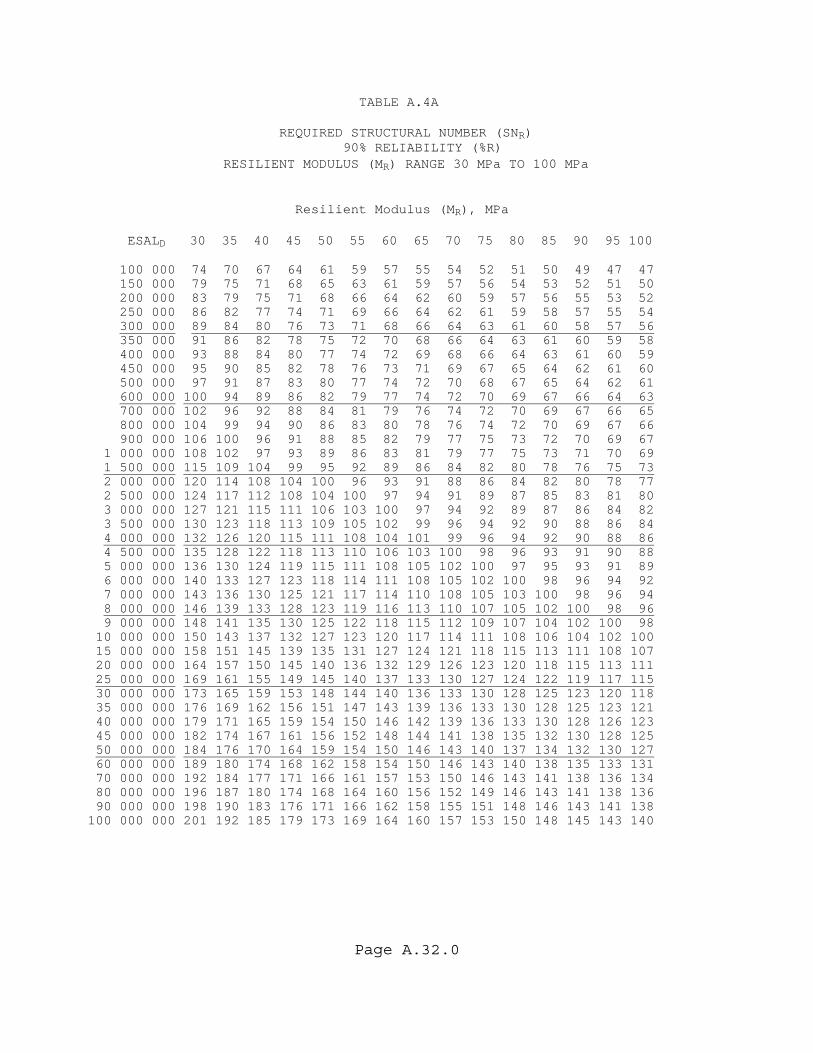
Page A.32.0
TABLE A.4A REQUIRED STRUCTURAL NUMBER (SNR) 90% RELIABILITY (%R) RESILIENT MODULUS (MR) RANGE 30 MPa TO 100 MPa Resilient Modulus (MR), MPa ESALD 30 35 40 45 50 55 60 65 70 75 80 85 90 95 100 100 000 74 70 67 64 61 59 57 55 54 52 51 50 49 47 47 150 000 79 75 71 68 65 63 61 59 57 56 54 53 52 51 50 200 000 83 79 75 71 68 66 64 62 60 59 57 56 55 53 52 250 000 86 82 77 74 71 69 66 64 62 61 59 58 57 55 54 300 000 89 84 80 76 73 71 68 66 64 63 61 60 58 57 56 350 000 91 86 82 78 75 72 70 68 66 64 63 61 60 59 58 400 000 93 88 84 80 77 74 72 69 68 66 64 63 61 60 59 450 000 95 90 85 82 78 76 73 71 69 67 65 64 62 61 60 500 000 97 91 87 83 80 77 74 72 70 68 67 65 64 62 61 600 000 100 94 89 86 82 79 77 74 72 70 69 67 66 64 63 700 000 102 96 92 88 84 81 79 76 74 72 70 69 67 66 65 800 000 104 99 94 90 86 83 80 78 76 74 72 70 69 67 66 900 000 106 100 96 91 88 85 82 79 77 75 73 72 70 69 67 1 000 000 108 102 97 93 89 86 83 81 79 77 75 73 71 70 69 1 500 000 115 109 104 99 95 92 89 86 84 82 80 78 76 75 73 2 000 000 120 114 108 104 100 96 93 91 88 86 84 82 80 78 77 2 500 000 124 117 112 108 104 100 97 94 91 89 87 85 83 81 80 3 000 000 127 121 115 111 106 103 100 97 94 92 89 87 86 84 82 3 500 000 130 123 118 113 109 105 102 99 96 94 92 90 88 86 84 4 000 000 132 126 120 115 111 108 104 101 99 96 94 92 90 88 86 4 500 000 135 128 122 118 113 110 106 103 100 98 96 93 91 90 88 5 000 000 136 130 124 119 115 111 108 105 102 100 97 95 93 91 89 6 000 000 140 133 127 123 118 114 111 108 105 102 100 98 96 94 92 7 000 000 143 136 130 125 121 117 114 110 108 105 103 100 98 96 94 8 000 000 146 139 133 128 123 119 116 113 110 107 105 102 100 98 96 9 000 000 148 141 135 130 125 122 118 115 112 109 107 104 102 100 98 10 000 000 150 143 137 132 127 123 120 117 114 111 108 106 104 102 100 15 000 000 158 151 145 139 135 131 127 124 121 118 115 113 111 108 107 20 000 000 164 157 150 145 140 136 132 129 126 123 120 118 115 113 111 25 000 000 169 161 155 149 145 140 137 133 130 127 124 122 119 117 115 30 000 000 173 165 159 153 148 144 140 136 133 130 128 125 123 120 118 35 000 000 176 169 162 156 151 147 143 139 136 133 130 128 125 123 121 40 000 000 179 171 165 159 154 150 146 142 139 136 133 130 128 126 123 45 000 000 182 174 167 161 156 152 148 144 141 138 135 132 130 128 125 50 000 000 184 176 170 164 159 154 150 146 143 140 137 134 132 130 127 60 000 000 189 180 174 168 162 158 154 150 146 143 140 138 135 133 131 70 000 000 192 184 177 171 166 161 157 153 150 146 143 141 138 136 134 80 000 000 196 187 180 174 168 164 160 156 152 149 146 143 141 138 136 90 000 000 198 190 183 176 171 166 162 158 155 151 148 146 143 141 138 100 000 000 201 192 185 179 173 169 164 160 157 153 150 148 145 143 140

Page A.33.0
TABLE A.4B REQUIRED STRUCTURAL NUMBER (SNR) 90% RELIABILITY (%R) RESILIENT MODULUS (MR) RANGE 100 MPa TO 300 MPa Resilient Modulus (MR), MPa ESALD 100 110 120 130 140 150 160 170 180 190 200 225 250 275 300 100 000 47 45 43 42 41 39 38 37 36 36 35 33 32 30 29 150 000 50 48 46 45 44 42 41 40 39 38 38 36 34 33 31 200 000 52 50 49 47 46 45 43 42 41 40 40 38 36 35 33 250 000 54 52 51 49 48 46 45 44 43 42 41 39 38 36 35 300 000 56 54 52 51 49 48 47 45 44 43 43 41 39 37 36 350 000 58 55 54 52 50 49 48 47 46 45 44 42 40 38 37 400 000 59 57 55 53 52 50 49 48 47 46 45 43 41 39 38 450 000 60 58 56 54 53 51 50 49 48 47 46 44 42 40 39 500 000 61 59 57 55 54 52 51 50 49 47 47 44 42 41 39 600 000 63 61 59 57 55 54 52 51 50 49 48 46 44 42 41 700 000 65 62 60 58 57 55 54 53 51 50 49 47 45 43 42 800 000 66 64 62 60 58 56 55 54 53 51 50 48 46 44 43 900 000 67 65 63 61 59 58 56 55 54 52 51 49 47 45 44 1 000 000 69 66 64 62 60 59 57 56 55 53 52 50 48 46 45 1 500 000 73 71 68 66 64 63 61 60 58 57 56 54 51 49 48 2 000 000 77 74 72 69 68 66 64 63 61 60 59 56 54 52 50 2 500 000 80 77 74 72 70 68 67 65 64 62 61 58 56 54 52 3 000 000 82 79 77 74 72 70 69 67 66 64 63 60 58 56 54 3 500 000 84 81 79 76 74 72 70 69 67 66 65 62 59 57 55 4 000 000 86 83 80 78 76 74 72 70 69 67 66 63 61 58 56 4 500 000 88 85 82 79 77 75 73 72 70 69 67 64 62 60 58 5 000 000 89 86 83 81 79 77 75 73 71 70 69 65 63 61 59 6 000 000 92 89 86 83 81 79 77 75 74 72 71 67 65 62 60 7 000 000 94 91 88 85 83 81 79 77 75 74 72 69 66 64 62 8 000 000 96 93 90 87 85 83 81 79 77 76 74 71 68 66 63 9 000 000 98 95 92 89 87 84 82 80 79 77 76 72 69 67 65 10 000 000 100 97 93 91 88 86 84 82 80 78 77 73 71 68 66 15 000 000 107 103 100 97 94 92 90 87 86 84 82 79 75 73 70 20 000 000 111 108 104 101 99 96 94 92 90 88 86 82 79 76 74 25 000 000 115 111 108 105 102 100 97 95 93 91 89 86 82 79 77 30 000 000 118 114 111 108 105 102 100 98 96 94 92 88 85 82 79 35 000 000 121 117 114 110 108 105 103 100 98 96 94 90 87 84 81 40 000 000 123 119 116 113 110 107 105 102 100 98 96 92 89 86 83 45 000 000 125 122 118 115 112 109 107 104 102 100 98 94 90 87 84 50 000 000 127 123 120 117 114 111 108 106 104 102 100 96 92 89 86 60 000 000 131 127 123 120 117 114 111 109 107 105 103 99 95 91 88 70 000 000 134 130 126 123 119 117 114 112 109 107 105 101 97 94 91 80 000 000 136 132 128 125 122 119 116 114 112 110 108 103 99 96 93 90 000 000 138 134 130 127 124 121 118 116 114 112 110 105 101 98 95 100 000 000 140 136 132 129 126 123 120 118 116 113 111 107 103 99 96

Page A.34.0
TABLE A.5A REQUIRED STRUCTURAL NUMBER (SNR) 92% RELIABILITY (%R) RESILIENT MODULUS (MR) RANGE 30 MPa TO 100 MPa Resilient Modulus (MR), MPa ESALD 30 35 40 45 50 55 60 65 70 75 80 85 90 95 100 100 000 76 72 68 65 62 60 58 56 55 53 52 51 50 49 48 150 000 81 77 73 69 67 64 62 60 59 57 56 54 53 52 51 200 000 85 80 76 73 70 67 65 63 61 60 58 57 56 55 53 250 000 88 83 79 76 73 70 68 66 64 62 61 59 58 57 56 300 000 91 86 82 78 75 72 70 68 66 64 62 61 60 58 57 350 000 93 88 84 80 77 74 72 69 67 66 64 63 61 60 59 400 000 95 90 86 82 78 76 73 71 69 67 65 64 63 61 60 450 000 97 92 87 83 80 77 75 72 70 68 67 65 64 63 61 500 000 99 93 89 85 81 79 76 74 72 70 68 66 65 64 62 600 000 102 96 91 87 84 81 78 76 74 72 70 68 67 66 64 700 000 104 98 94 90 86 83 80 78 76 74 72 70 69 67 66 800 000 106 101 96 92 88 85 82 80 77 75 73 72 70 69 67 900 000 108 102 98 93 90 87 84 81 79 77 75 73 72 70 69 1 000 000 110 104 99 95 91 88 85 83 80 78 76 75 73 71 70 1 500 000 117 111 106 101 97 94 91 88 86 84 82 80 78 76 75 2 000 000 122 116 110 106 102 98 95 93 90 88 86 84 82 80 79 2 500 000 126 120 114 110 106 102 99 96 93 91 89 87 85 83 81 3 000 000 129 123 117 113 109 105 102 99 96 94 91 89 87 86 84 3 500 000 132 126 120 115 111 108 104 101 98 96 94 92 90 88 86 4 000 000 135 128 123 118 113 110 106 103 101 98 96 94 92 90 88 4 500 000 137 130 125 120 115 112 108 105 102 100 98 95 93 91 90 5 000 000 139 132 127 122 117 114 110 107 104 102 99 97 95 93 91 6 000 000 142 136 130 125 121 117 113 110 107 105 102 100 98 96 94 7 000 000 145 139 133 128 123 119 116 113 110 107 105 102 100 98 96 8 000 000 148 141 135 130 126 122 118 115 112 109 107 104 102 100 98 9 000 000 150 143 137 132 128 124 120 117 114 111 109 106 104 102 100 10 000 000 153 145 139 134 130 126 122 119 116 113 111 108 106 104 102 15 000 000 161 153 147 142 137 133 129 126 123 120 117 115 113 111 109 20 000 000 167 159 153 148 143 139 135 131 128 125 123 120 118 116 113 25 000 000 172 164 158 152 147 143 139 135 132 129 127 124 122 119 117 30 000 000 176 168 161 156 151 146 142 139 136 133 130 127 125 123 121 35 000 000 179 171 165 159 154 149 145 142 139 136 133 130 128 125 123 40 000 000 182 174 167 162 157 152 148 144 141 138 135 133 130 128 126 45 000 000 185 177 170 164 159 154 150 147 143 140 137 135 132 130 128 50 000 000 187 179 172 166 161 157 153 149 145 142 139 137 134 132 130 60 000 000 192 183 176 170 165 160 156 152 149 146 143 140 138 135 133 70 000 000 195 187 180 174 168 164 159 156 152 149 146 143 141 138 136 80 000 000 199 190 183 177 171 166 162 158 155 152 149 146 143 141 139 90 000 000 202 193 186 179 174 169 165 161 157 154 151 148 146 143 141 100 000 000 204 195 188 182 176 171 167 163 159 156 153 150 148 145 143
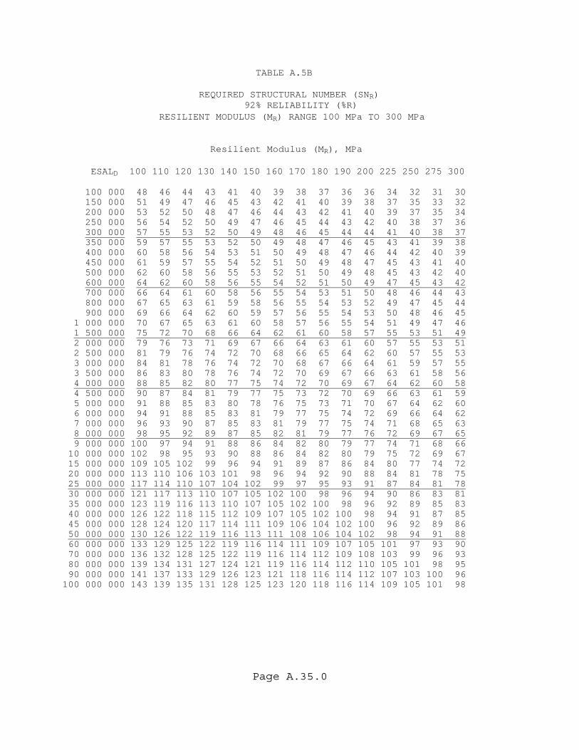
Page A.35.0
TABLE A.5B REQUIRED STRUCTURAL NUMBER (SNR) 92% RELIABILITY (%R) RESILIENT MODULUS (MR) RANGE 100 MPa TO 300 MPa Resilient Modulus (MR), MPa ESALD 100 110 120 130 140 150 160 170 180 190 200 225 250 275 300 100 000 48 46 44 43 41 40 39 38 37 36 36 34 32 31 30 150 000 51 49 47 46 45 43 42 41 40 39 38 37 35 33 32 200 000 53 52 50 48 47 46 44 43 42 41 40 39 37 35 34 250 000 56 54 52 50 49 47 46 45 44 43 42 40 38 37 36 300 000 57 55 53 52 50 49 48 46 45 44 44 41 40 38 37 350 000 59 57 55 53 52 50 49 48 47 46 45 43 41 39 38 400 000 60 58 56 54 53 51 50 49 48 47 46 44 42 40 39 450 000 61 59 57 55 54 52 51 50 49 48 47 45 43 41 40 500 000 62 60 58 56 55 53 52 51 50 49 48 45 43 42 40 600 000 64 62 60 58 56 55 54 52 51 50 49 47 45 43 42 700 000 66 64 61 60 58 56 55 54 53 51 50 48 46 44 43 800 000 67 65 63 61 59 58 56 55 54 53 52 49 47 45 44 900 000 69 66 64 62 60 59 57 56 55 54 53 50 48 46 45 1 000 000 70 67 65 63 61 60 58 57 56 55 54 51 49 47 46 1 500 000 75 72 70 68 66 64 62 61 60 58 57 55 53 51 49 2 000 000 79 76 73 71 69 67 66 64 63 61 60 57 55 53 51 2 500 000 81 79 76 74 72 70 68 66 65 64 62 60 57 55 53 3 000 000 84 81 78 76 74 72 70 68 67 66 64 61 59 57 55 3 500 000 86 83 80 78 76 74 72 70 69 67 66 63 61 58 56 4 000 000 88 85 82 80 77 75 74 72 70 69 67 64 62 60 58 4 500 000 90 87 84 81 79 77 75 73 72 70 69 66 63 61 59 5 000 000 91 88 85 83 80 78 76 75 73 71 70 67 64 62 60 6 000 000 94 91 88 85 83 81 79 77 75 74 72 69 66 64 62 7 000 000 96 93 90 87 85 83 81 79 77 75 74 71 68 65 63 8 000 000 98 95 92 89 87 85 82 81 79 77 76 72 69 67 65 9 000 000 100 97 94 91 88 86 84 82 80 79 77 74 71 68 66 10 000 000 102 98 95 93 90 88 86 84 82 80 79 75 72 69 67 15 000 000 109 105 102 99 96 94 91 89 87 86 84 80 77 74 72 20 000 000 113 110 106 103 101 98 96 94 92 90 88 84 81 78 75 25 000 000 117 114 110 107 104 102 99 97 95 93 91 87 84 81 78 30 000 000 121 117 113 110 107 105 102 100 98 96 94 90 86 83 81 35 000 000 123 119 116 113 110 107 105 102 100 98 96 92 89 85 83 40 000 000 126 122 118 115 112 109 107 105 102 100 98 94 91 87 85 45 000 000 128 124 120 117 114 111 109 106 104 102 100 96 92 89 86 50 000 000 130 126 122 119 116 113 111 108 106 104 102 98 94 91 88 60 000 000 133 129 125 122 119 116 114 111 109 107 105 101 97 93 90 70 000 000 136 132 128 125 122 119 116 114 112 109 108 103 99 96 93 80 000 000 139 134 131 127 124 121 119 116 114 112 110 105 101 98 95 90 000 000 141 137 133 129 126 123 121 118 116 114 112 107 103 100 96 100 000 000 143 139 135 131 128 125 123 120 118 116 114 109 105 101 98

Page A.36.0
TABLE A.6A REQUIRED STRUCTURAL NUMBER (SNR) 94% RELIABILITY (%R) RESILIENT MODULUS (MR) RANGE 30 MPa TO 100 MPa Resilient Modulus (MR), MPa ESALD 30 35 40 45 50 55 60 65 70 75 80 85 90 95 100 100 000 78 73 70 67 64 62 60 58 56 55 53 52 51 50 49 150 000 83 79 75 71 68 66 64 62 60 59 57 56 55 53 52 200 000 87 82 78 75 72 69 67 65 63 61 60 58 57 56 55 250 000 91 85 81 78 74 72 69 67 65 64 62 61 59 58 57 300 000 93 88 84 80 77 74 72 69 67 66 64 63 61 60 59 350 000 96 90 86 82 79 76 73 71 69 67 66 64 63 62 60 400 000 98 92 88 84 81 78 75 73 71 69 67 66 64 63 62 450 000 100 94 89 85 82 79 77 74 72 70 69 67 65 64 63 500 000 101 96 91 87 84 81 78 76 73 71 70 68 67 65 64 600 000 104 98 94 90 86 83 80 78 76 74 72 70 69 67 66 700 000 107 101 96 92 88 85 82 80 78 76 74 72 70 69 68 800 000 109 103 98 94 90 87 84 82 79 77 75 74 72 71 69 900 000 111 105 100 96 92 89 86 83 81 79 77 75 73 72 71 1 000 000 113 107 102 97 94 90 87 85 82 80 78 76 75 73 72 1 500 000 120 114 108 104 100 96 93 91 88 86 84 82 80 78 77 2 000 000 125 118 113 109 104 101 98 95 92 90 88 86 84 82 81 2 500 000 129 122 117 112 108 105 101 98 96 93 91 89 87 85 84 3 000 000 132 126 120 115 111 108 104 101 98 96 94 92 90 88 86 3 500 000 135 128 123 118 114 110 107 104 101 98 96 94 92 90 88 4 000 000 138 131 125 120 116 112 109 106 103 101 98 96 94 92 90 4 500 000 140 133 127 123 118 114 111 108 105 102 100 98 96 94 92 5 000 000 142 135 129 124 120 116 113 110 107 104 102 99 97 95 94 6 000 000 145 139 133 128 123 119 116 113 110 107 105 102 100 98 96 7 000 000 148 141 136 131 126 122 119 115 112 110 107 105 103 101 99 8 000 000 151 144 138 133 128 124 121 118 115 112 109 107 105 103 101 9 000 000 154 146 140 135 131 127 123 120 117 114 111 109 107 105 103 10 000 000 156 148 142 137 133 129 125 122 119 116 113 111 109 106 105 15 000 000 164 157 150 145 140 136 132 129 126 123 120 118 115 113 111 20 000 000 170 163 156 151 146 142 138 134 131 128 125 123 120 118 116 25 000 000 175 167 161 155 150 146 142 138 135 132 129 127 124 122 120 30 000 000 179 171 165 159 154 149 145 142 139 136 133 130 128 125 123 35 000 000 183 175 168 162 157 153 149 145 142 138 136 133 131 128 126 40 000 000 186 178 171 165 160 155 151 147 144 141 138 135 133 131 128 45 000 000 189 180 173 167 162 158 154 150 146 143 140 138 135 133 131 50 000 000 191 183 176 170 164 160 156 152 148 145 142 140 137 135 133 60 000 000 195 187 180 174 168 164 159 156 152 149 146 143 141 138 136 70 000 000 199 191 183 177 172 167 163 159 155 152 149 146 144 141 139 80 000 000 202 194 186 180 175 170 165 162 158 155 152 149 146 144 141 90 000 000 205 197 189 183 177 172 168 164 160 157 154 151 149 146 144 100 000 000 208 199 192 185 180 175 170 166 163 159 156 153 151 148 146
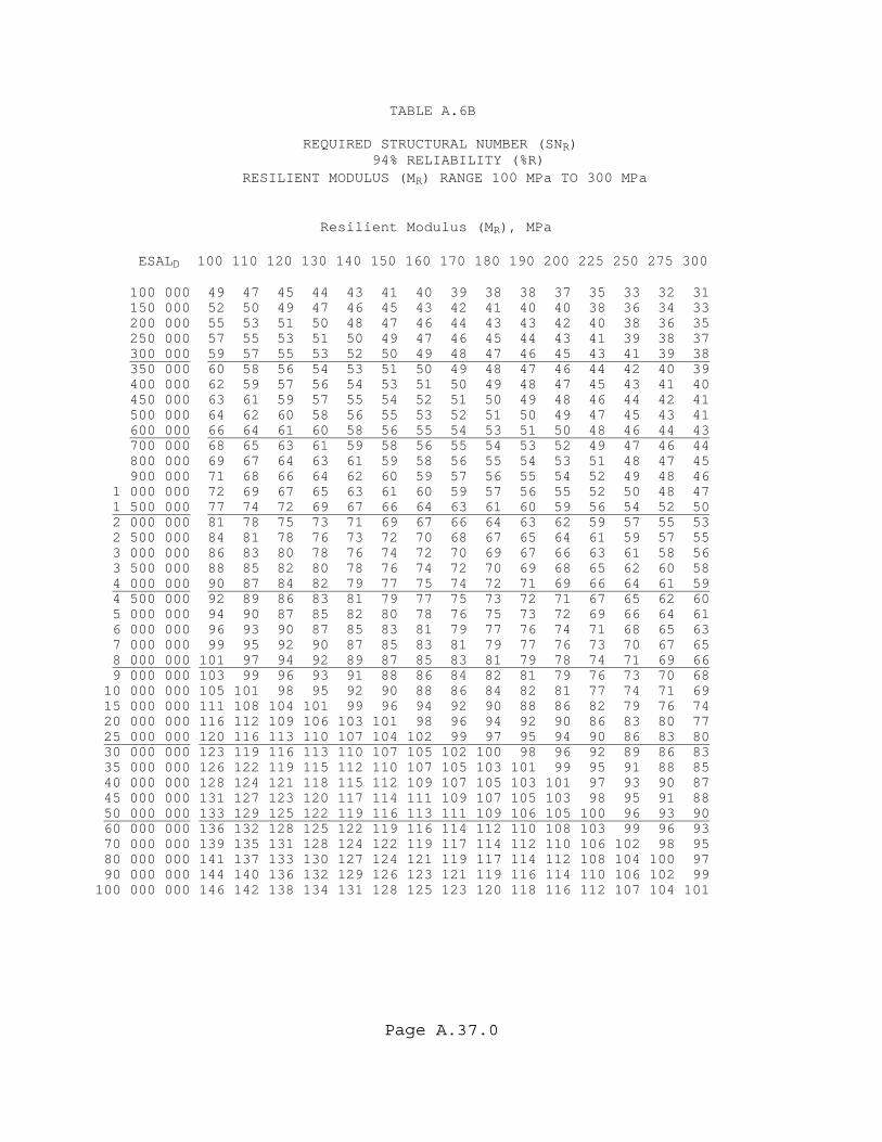
Page A.37.0
TABLE A.6B REQUIRED STRUCTURAL NUMBER (SNR) 94% RELIABILITY (%R) RESILIENT MODULUS (MR) RANGE 100 MPa TO 300 MPa Resilient Modulus (MR), MPa ESALD 100 110 120 130 140 150 160 170 180 190 200 225 250 275 300 100 000 49 47 45 44 43 41 40 39 38 38 37 35 33 32 31 150 000 52 50 49 47 46 45 43 42 41 40 40 38 36 34 33 200 000 55 53 51 50 48 47 46 44 43 43 42 40 38 36 35 250 000 57 55 53 51 50 49 47 46 45 44 43 41 39 38 37 300 000 59 57 55 53 52 50 49 48 47 46 45 43 41 39 38 350 000 60 58 56 54 53 51 50 49 48 47 46 44 42 40 39 400 000 62 59 57 56 54 53 51 50 49 48 47 45 43 41 40 450 000 63 61 59 57 55 54 52 51 50 49 48 46 44 42 41 500 000 64 62 60 58 56 55 53 52 51 50 49 47 45 43 41 600 000 66 64 61 60 58 56 55 54 53 51 50 48 46 44 43 700 000 68 65 63 61 59 58 56 55 54 53 52 49 47 46 44 800 000 69 67 64 63 61 59 58 56 55 54 53 51 48 47 45 900 000 71 68 66 64 62 60 59 57 56 55 54 52 49 48 46 1 000 000 72 69 67 65 63 61 60 59 57 56 55 52 50 48 47 1 500 000 77 74 72 69 67 66 64 63 61 60 59 56 54 52 50 2 000 000 81 78 75 73 71 69 67 66 64 63 62 59 57 55 53 2 500 000 84 81 78 76 73 72 70 68 67 65 64 61 59 57 55 3 000 000 86 83 80 78 76 74 72 70 69 67 66 63 61 58 56 3 500 000 88 85 82 80 78 76 74 72 70 69 68 65 62 60 58 4 000 000 90 87 84 82 79 77 75 74 72 71 69 66 64 61 59 4 500 000 92 89 86 83 81 79 77 75 73 72 71 67 65 62 60 5 000 000 94 90 87 85 82 80 78 76 75 73 72 69 66 64 61 6 000 000 96 93 90 87 85 83 81 79 77 76 74 71 68 65 63 7 000 000 99 95 92 90 87 85 83 81 79 77 76 73 70 67 65 8 000 000 101 97 94 92 89 87 85 83 81 79 78 74 71 69 66 9 000 000 103 99 96 93 91 88 86 84 82 81 79 76 73 70 68 10 000 000 105 101 98 95 92 90 88 86 84 82 81 77 74 71 69 15 000 000 111 108 104 101 99 96 94 92 90 88 86 82 79 76 74 20 000 000 116 112 109 106 103 101 98 96 94 92 90 86 83 80 77 25 000 000 120 116 113 110 107 104 102 99 97 95 94 90 86 83 80 30 000 000 123 119 116 113 110 107 105 102 100 98 96 92 89 86 83 35 000 000 126 122 119 115 112 110 107 105 103 101 99 95 91 88 85 40 000 000 128 124 121 118 115 112 109 107 105 103 101 97 93 90 87 45 000 000 131 127 123 120 117 114 111 109 107 105 103 98 95 91 88 50 000 000 133 129 125 122 119 116 113 111 109 106 105 100 96 93 90 60 000 000 136 132 128 125 122 119 116 114 112 110 108 103 99 96 93 70 000 000 139 135 131 128 124 122 119 117 114 112 110 106 102 98 95 80 000 000 141 137 133 130 127 124 121 119 117 114 112 108 104 100 97 90 000 000 144 140 136 132 129 126 123 121 119 116 114 110 106 102 99 100 000 000 146 142 138 134 131 128 125 123 120 118 116 112 107 104 101
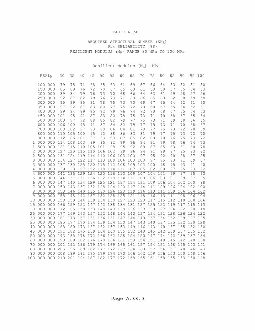
Page A.38.0
TABLE A.7A REQUIRED STRUCTURAL NUMBER (SNR) 95% RELIABILITY (%R) RESILIENT MODULUS (MR) RANGE 30 MPa TO 100 MPa Resilient Modulus (MR), MPa ESALD 30 35 40 45 50 55 60 65 70 75 80 85 90 95 100 100 000 79 75 71 68 65 63 61 59 57 56 54 53 52 51 50 150 000 85 80 76 72 70 67 65 63 61 59 58 57 55 54 53 200 000 89 84 79 76 73 70 68 66 64 62 61 59 58 57 56 250 000 92 87 82 79 76 73 71 68 66 65 63 62 60 59 58 300 000 95 89 85 81 78 75 73 70 69 67 65 64 62 61 60 350 000 97 92 87 83 80 77 75 72 70 68 67 65 64 62 61 400 000 99 94 89 85 82 79 76 74 72 70 68 67 65 64 63 450 000 101 95 91 87 83 80 78 75 73 71 70 68 67 65 64 500 000 103 97 92 88 85 82 79 77 75 73 71 69 68 66 65 600 000 106 100 95 91 87 84 82 79 77 75 73 71 70 68 67 700 000 108 102 97 93 90 86 84 81 79 77 75 73 72 70 69 800 000 110 105 100 95 92 88 86 83 81 79 77 75 73 72 70 900 000 112 106 101 97 93 90 87 85 82 80 78 76 75 73 72 1 000 000 114 108 103 99 95 92 89 86 84 81 79 78 76 74 73 1 500 000 121 115 110 105 101 98 95 92 89 87 85 83 81 80 78 2 000 000 127 120 115 110 106 102 99 96 94 91 89 87 85 83 82 2 500 000 131 124 119 114 110 106 103 100 97 95 92 90 88 87 85 3 000 000 134 127 122 117 113 109 106 103 100 97 95 93 91 89 87 3 500 000 137 130 125 120 115 112 108 105 102 100 98 95 93 91 90 4 000 000 139 133 127 122 118 114 111 107 105 102 100 97 95 93 92 4 500 000 142 135 129 124 120 116 113 109 107 104 101 99 97 95 93 5 000 000 144 137 131 126 122 118 114 111 108 106 103 101 99 97 95 6 000 000 147 140 134 129 125 121 117 114 111 109 106 104 102 100 98 7 000 000 150 143 137 132 128 124 120 117 114 111 109 106 104 102 100 8 000 000 153 146 140 135 130 126 123 119 116 113 111 109 106 104 102 9 000 000 155 148 142 137 132 128 125 121 118 116 113 111 108 106 104 10 000 000 158 150 144 139 134 130 127 123 120 117 115 112 110 108 106 15 000 000 166 159 152 147 142 138 134 131 127 125 122 119 117 115 113 20 000 000 172 165 158 153 148 143 139 136 133 130 127 124 122 120 118 25 000 000 177 169 163 157 152 148 144 140 137 134 131 128 126 124 122 30 000 000 181 173 167 161 156 151 147 144 140 137 134 132 129 127 125 35 000 000 185 177 170 164 159 154 150 147 143 140 137 135 132 130 128 40 000 000 188 180 173 167 162 157 153 149 146 143 140 137 135 132 130 45 000 000 191 182 175 169 164 160 155 152 148 145 142 139 137 135 132 50 000 000 193 185 178 172 166 162 158 154 150 147 144 142 139 137 134 60 000 000 198 189 182 176 170 166 161 158 154 151 148 145 142 140 138 70 000 000 201 193 186 179 174 169 165 161 157 154 151 148 145 143 141 80 000 000 205 196 189 182 177 172 167 164 160 157 154 151 148 146 143 90 000 000 208 199 191 185 179 174 170 166 162 159 156 153 150 148 146 100 000 000 210 201 194 187 182 177 172 168 165 161 158 155 153 150 148
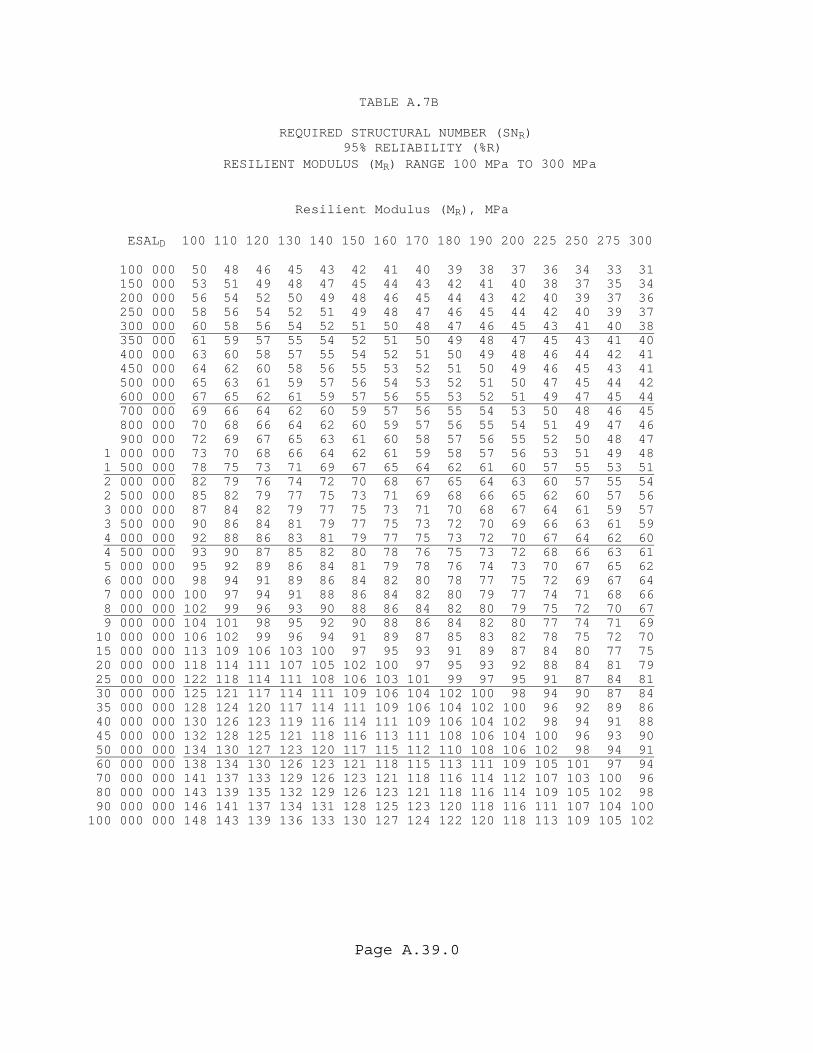
Page A.39.0
TABLE A.7B REQUIRED STRUCTURAL NUMBER (SNR) 95% RELIABILITY (%R) RESILIENT MODULUS (MR) RANGE 100 MPa TO 300 MPa Resilient Modulus (MR), MPa ESALD 100 110 120 130 140 150 160 170 180 190 200 225 250 275 300 100 000 50 48 46 45 43 42 41 40 39 38 37 36 34 33 31 150 000 53 51 49 48 47 45 44 43 42 41 40 38 37 35 34 200 000 56 54 52 50 49 48 46 45 44 43 42 40 39 37 36 250 000 58 56 54 52 51 49 48 47 46 45 44 42 40 39 37 300 000 60 58 56 54 52 51 50 48 47 46 45 43 41 40 38 350 000 61 59 57 55 54 52 51 50 49 48 47 45 43 41 40 400 000 63 60 58 57 55 54 52 51 50 49 48 46 44 42 41 450 000 64 62 60 58 56 55 53 52 51 50 49 46 45 43 41 500 000 65 63 61 59 57 56 54 53 52 51 50 47 45 44 42 600 000 67 65 62 61 59 57 56 55 53 52 51 49 47 45 44 700 000 69 66 64 62 60 59 57 56 55 54 53 50 48 46 45 800 000 70 68 66 64 62 60 59 57 56 55 54 51 49 47 46 900 000 72 69 67 65 63 61 60 58 57 56 55 52 50 48 47 1 000 000 73 70 68 66 64 62 61 59 58 57 56 53 51 49 48 1 500 000 78 75 73 71 69 67 65 64 62 61 60 57 55 53 51 2 000 000 82 79 76 74 72 70 68 67 65 64 63 60 57 55 54 2 500 000 85 82 79 77 75 73 71 69 68 66 65 62 60 57 56 3 000 000 87 84 82 79 77 75 73 71 70 68 67 64 61 59 57 3 500 000 90 86 84 81 79 77 75 73 72 70 69 66 63 61 59 4 000 000 92 88 86 83 81 79 77 75 73 72 70 67 64 62 60 4 500 000 93 90 87 85 82 80 78 76 75 73 72 68 66 63 61 5 000 000 95 92 89 86 84 81 79 78 76 74 73 70 67 65 62 6 000 000 98 94 91 89 86 84 82 80 78 77 75 72 69 67 64 7 000 000 100 97 94 91 88 86 84 82 80 79 77 74 71 68 66 8 000 000 102 99 96 93 90 88 86 84 82 80 79 75 72 70 67 9 000 000 104 101 98 95 92 90 88 86 84 82 80 77 74 71 69 10 000 000 106 102 99 96 94 91 89 87 85 83 82 78 75 72 70 15 000 000 113 109 106 103 100 97 95 93 91 89 87 84 80 77 75 20 000 000 118 114 111 107 105 102 100 97 95 93 92 88 84 81 79 25 000 000 122 118 114 111 108 106 103 101 99 97 95 91 87 84 81 30 000 000 125 121 117 114 111 109 106 104 102 100 98 94 90 87 84 35 000 000 128 124 120 117 114 111 109 106 104 102 100 96 92 89 86 40 000 000 130 126 123 119 116 114 111 109 106 104 102 98 94 91 88 45 000 000 132 128 125 121 118 116 113 111 108 106 104 100 96 93 90 50 000 000 134 130 127 123 120 117 115 112 110 108 106 102 98 94 91 60 000 000 138 134 130 126 123 121 118 115 113 111 109 105 101 97 94 70 000 000 141 137 133 129 126 123 121 118 116 114 112 107 103 100 96 80 000 000 143 139 135 132 129 126 123 121 118 116 114 109 105 102 98 90 000 000 146 141 137 134 131 128 125 123 120 118 116 111 107 104 100 100 000 000 148 143 139 136 133 130 127 124 122 120 118 113 109 105 102

Page A.40.0
TABLE A.8A REQUIRED STRUCTURAL NUMBER (SNR) 96% RELIABILITY (%R) RESILIENT MODULUS (MR) RANGE 30 MPa TO 100 MPa Resilient Modulus (MR), MPa ESALD 30 35 40 45 50 55 60 65 70 75 80 85 90 95 100 100 000 81 76 72 69 66 64 62 60 58 57 55 54 53 52 51 150 000 86 81 77 74 71 68 66 64 62 61 59 58 56 55 54 200 000 90 85 81 77 74 72 69 67 65 64 62 61 59 58 57 250 000 94 88 84 80 77 74 72 70 68 66 64 63 61 60 59 300 000 96 91 86 83 79 77 74 72 70 68 66 65 63 62 61 350 000 99 93 89 85 81 79 76 74 72 70 68 66 65 64 62 400 000 101 95 91 87 83 80 78 75 73 71 70 68 66 65 64 450 000 103 97 92 88 85 82 79 77 75 73 71 69 68 66 65 500 000 105 99 94 90 86 83 81 78 76 74 72 70 69 68 66 600 000 108 102 97 93 89 86 83 81 78 76 74 73 71 70 68 700 000 110 104 99 95 91 88 85 83 80 78 76 75 73 71 70 800 000 112 106 101 97 93 90 87 84 82 80 78 76 75 73 72 900 000 114 108 103 99 95 92 89 86 84 82 80 78 76 74 73 1 000 000 116 110 105 101 97 93 90 88 85 83 81 79 77 76 74 1 500 000 123 117 112 107 103 100 96 94 91 89 87 85 83 81 79 2 000 000 129 122 117 112 108 104 101 98 95 93 91 89 87 85 83 2 500 000 133 126 121 116 112 108 105 102 99 96 94 92 90 88 86 3 000 000 136 129 124 119 115 111 108 104 102 99 97 95 93 91 89 3 500 000 139 132 127 122 117 114 110 107 104 102 99 97 95 93 91 4 000 000 142 135 129 124 120 116 112 109 106 104 101 99 97 95 93 4 500 000 144 137 131 126 122 118 114 111 108 106 103 101 99 97 95 5 000 000 146 139 133 128 124 120 116 113 110 107 105 103 101 99 97 6 000 000 149 142 137 131 127 123 119 116 113 110 108 106 103 101 100 7 000 000 153 145 139 134 130 126 122 119 116 113 111 108 106 104 102 8 000 000 155 148 142 137 132 128 124 121 118 115 113 110 108 106 104 9 000 000 158 150 144 139 134 130 127 123 120 117 115 112 110 108 106 10 000 000 160 153 146 141 136 132 129 125 122 119 117 114 112 110 108 15 000 000 168 161 154 149 144 140 136 133 129 126 124 121 119 117 115 20 000 000 175 167 160 155 150 145 142 138 135 132 129 126 124 122 120 25 000 000 180 172 165 159 154 150 146 142 139 136 133 131 128 126 124 30 000 000 184 176 169 163 158 154 149 146 142 139 137 134 131 129 127 35 000 000 187 179 172 166 161 157 153 149 145 142 139 137 134 132 130 40 000 000 191 182 175 169 164 159 155 152 148 145 142 139 137 134 132 45 000 000 193 185 178 172 167 162 158 154 150 147 144 142 139 137 134 50 000 000 196 187 180 174 169 164 160 156 153 149 146 144 141 139 136 60 000 000 200 192 184 178 173 168 164 160 156 153 150 147 145 142 140 70 000 000 204 195 188 182 176 171 167 163 159 156 153 150 148 145 143 80 000 000 208 199 191 185 179 174 170 166 162 159 156 153 150 148 145 90 000 000 211 202 194 188 182 177 172 168 165 161 158 155 153 150 148 100 000 000 213 204 197 190 184 179 175 171 167 164 160 157 155 152 150
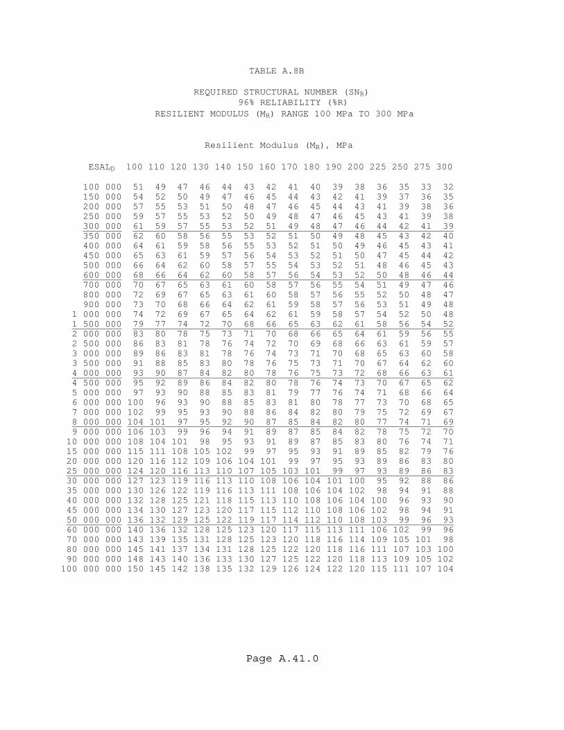
Page A.41.0
TABLE A.8B REQUIRED STRUCTURAL NUMBER (SNR) 96% RELIABILITY (%R) RESILIENT MODULUS (MR) RANGE 100 MPa TO 300 MPa Resilient Modulus (MR), MPa ESALD 100 110 120 130 140 150 160 170 180 190 200 225 250 275 300 100 000 51 49 47 46 44 43 42 41 40 39 38 36 35 33 32 150 000 54 52 50 49 47 46 45 44 43 42 41 39 37 36 35 200 000 57 55 53 51 50 48 47 46 45 44 43 41 39 38 36 250 000 59 57 55 53 52 50 49 48 47 46 45 43 41 39 38 300 000 61 59 57 55 53 52 51 49 48 47 46 44 42 41 39 350 000 62 60 58 56 55 53 52 51 50 49 48 45 43 42 40 400 000 64 61 59 58 56 55 53 52 51 50 49 46 45 43 41 450 000 65 63 61 59 57 56 54 53 52 51 50 47 45 44 42 500 000 66 64 62 60 58 57 55 54 53 52 51 48 46 45 43 600 000 68 66 64 62 60 58 57 56 54 53 52 50 48 46 44 700 000 70 67 65 63 61 60 58 57 56 55 54 51 49 47 46 800 000 72 69 67 65 63 61 60 58 57 56 55 52 50 48 47 900 000 73 70 68 66 64 62 61 59 58 57 56 53 51 49 48 1 000 000 74 72 69 67 65 64 62 61 59 58 57 54 52 50 48 1 500 000 79 77 74 72 70 68 66 65 63 62 61 58 56 54 52 2 000 000 83 80 78 75 73 71 70 68 66 65 64 61 59 56 55 2 500 000 86 83 81 78 76 74 72 70 69 68 66 63 61 59 57 3 000 000 89 86 83 81 78 76 74 73 71 70 68 65 63 60 58 3 500 000 91 88 85 83 80 78 76 75 73 71 70 67 64 62 60 4 000 000 93 90 87 84 82 80 78 76 75 73 72 68 66 63 61 4 500 000 95 92 89 86 84 82 80 78 76 74 73 70 67 65 62 5 000 000 97 93 90 88 85 83 81 79 77 76 74 71 68 66 64 6 000 000 100 96 93 90 88 85 83 81 80 78 77 73 70 68 65 7 000 000 102 99 95 93 90 88 86 84 82 80 79 75 72 69 67 8 000 000 104 101 97 95 92 90 87 85 84 82 80 77 74 71 69 9 000 000 106 103 99 96 94 91 89 87 85 84 82 78 75 72 70 10 000 000 108 104 101 98 95 93 91 89 87 85 83 80 76 74 71 15 000 000 115 111 108 105 102 99 97 95 93 91 89 85 82 79 76 20 000 000 120 116 112 109 106 104 101 99 97 95 93 89 86 83 80 25 000 000 124 120 116 113 110 107 105 103 101 99 97 93 89 86 83 30 000 000 127 123 119 116 113 110 108 106 104 101 100 95 92 88 86 35 000 000 130 126 122 119 116 113 111 108 106 104 102 98 94 91 88 40 000 000 132 128 125 121 118 115 113 110 108 106 104 100 96 93 90 45 000 000 134 130 127 123 120 117 115 112 110 108 106 102 98 94 91 50 000 000 136 132 129 125 122 119 117 114 112 110 108 103 99 96 93 60 000 000 140 136 132 128 125 123 120 117 115 113 111 106 102 99 96 70 000 000 143 139 135 131 128 125 123 120 118 116 114 109 105 101 98 80 000 000 145 141 137 134 131 128 125 122 120 118 116 111 107 103 100 90 000 000 148 143 140 136 133 130 127 125 122 120 118 113 109 105 102 100 000 000 150 145 142 138 135 132 129 126 124 122 120 115 111 107 104
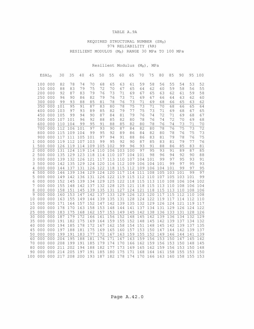
Page A.42.0
TABLE A.9A REQUIRED STRUCTURAL NUMBER (SNR) 97% RELIABILITY (%R) RESILIENT MODULUS (MR) RANGE 30 MPa TO 100 MPa Resilient Modulus (MR), MPa ESALD 30 35 40 45 50 55 60 65 70 75 80 85 90 95 100 100 000 82 78 74 70 68 65 63 61 59 58 56 55 54 53 52 150 000 88 83 79 75 72 70 67 65 64 62 60 59 58 56 55 200 000 92 87 83 79 76 73 71 69 67 65 63 62 61 59 58 250 000 96 90 86 82 79 76 73 71 69 67 66 64 63 62 60 300 000 99 93 88 85 81 78 76 73 71 69 68 66 65 63 62 350 000 101 95 91 87 83 80 78 75 73 71 70 68 66 65 64 400 000 103 97 93 89 85 82 79 77 75 73 71 69 68 67 65 450 000 105 99 94 90 87 84 81 79 76 74 72 71 69 68 67 500 000 107 101 96 92 88 85 82 80 78 76 74 72 70 69 68 600 000 110 104 99 95 91 88 85 82 80 78 76 74 73 71 70 700 000 112 106 101 97 93 90 87 84 82 80 78 76 75 73 72 800 000 115 109 104 99 95 92 89 86 84 82 80 78 76 75 73 900 000 117 111 105 101 97 94 91 88 86 83 81 79 78 76 75 1 000 000 119 112 107 103 99 95 92 90 87 85 83 81 79 77 76 1 500 000 126 119 114 109 105 102 99 96 93 91 88 86 85 83 81 2 000 000 131 124 119 114 110 106 103 100 97 95 93 91 89 87 85 2 500 000 135 129 123 118 114 110 107 104 101 98 96 94 92 90 88 3 000 000 139 132 126 121 117 113 110 107 104 101 99 97 95 93 91 3 500 000 142 135 129 124 120 116 112 109 106 104 101 99 97 95 93 4 000 000 144 137 131 126 122 118 115 112 109 106 104 101 99 97 95 4 500 000 146 139 134 129 124 120 117 114 111 108 105 103 101 99 97 5 000 000 149 142 136 131 126 122 119 115 112 110 107 105 103 101 99 6 000 000 152 145 139 134 129 125 122 118 115 113 110 108 106 104 102 7 000 000 155 148 142 137 132 128 125 121 118 115 113 110 108 106 104 8 000 000 158 151 145 139 135 131 127 124 121 118 115 113 110 108 106 9 000 000 160 153 147 142 137 133 129 126 123 120 117 115 112 110 108 10 000 000 163 155 149 144 139 135 131 128 124 122 119 117 114 112 110 15 000 000 171 164 157 152 147 142 139 135 132 129 126 124 121 119 117 20 000 000 178 170 163 158 153 148 144 141 137 134 131 129 126 124 122 25 000 000 183 175 168 162 157 153 149 145 142 138 136 133 131 128 126 30 000 000 187 179 172 166 161 156 152 148 145 142 139 136 134 132 129 35 000 000 191 182 175 169 164 159 155 152 148 145 142 139 137 134 132 40 000 000 194 185 178 172 167 162 158 154 151 148 145 142 139 137 135 45 000 000 197 188 181 175 169 165 160 157 153 150 147 144 142 139 137 50 000 000 199 191 183 177 172 167 163 159 155 152 149 146 144 141 139 60 000 000 204 195 188 181 176 171 167 163 159 156 153 150 147 145 142 70 000 000 208 199 191 185 179 174 170 166 162 159 156 153 150 148 145 80 000 000 211 202 194 188 182 177 173 169 165 162 159 156 153 150 148 90 000 000 214 205 197 191 185 180 175 171 168 164 161 158 155 153 150 100 000 000 217 208 200 193 187 182 178 174 170 166 163 160 158 155 153
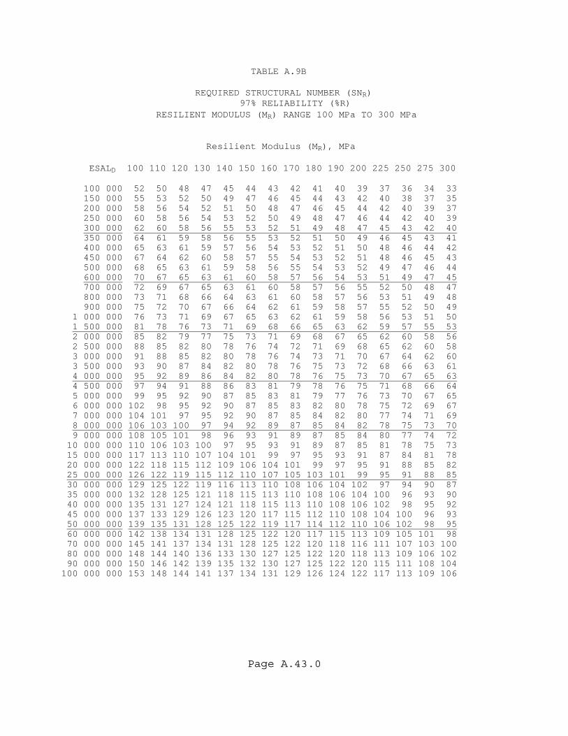
Page A.43.0
TABLE A.9B REQUIRED STRUCTURAL NUMBER (SNR) 97% RELIABILITY (%R) RESILIENT MODULUS (MR) RANGE 100 MPa TO 300 MPa Resilient Modulus (MR), MPa ESALD 100 110 120 130 140 150 160 170 180 190 200 225 250 275 300 100 000 52 50 48 47 45 44 43 42 41 40 39 37 36 34 33 150 000 55 53 52 50 49 47 46 45 44 43 42 40 38 37 35 200 000 58 56 54 52 51 50 48 47 46 45 44 42 40 39 37 250 000 60 58 56 54 53 52 50 49 48 47 46 44 42 40 39 300 000 62 60 58 56 55 53 52 51 49 48 47 45 43 42 40 350 000 64 61 59 58 56 55 53 52 51 50 49 46 45 43 41 400 000 65 63 61 59 57 56 54 53 52 51 50 48 46 44 42 450 000 67 64 62 60 58 57 55 54 53 52 51 48 46 45 43 500 000 68 65 63 61 59 58 56 55 54 53 52 49 47 46 44 600 000 70 67 65 63 61 60 58 57 56 54 53 51 49 47 45 700 000 72 69 67 65 63 61 60 58 57 56 55 52 50 48 47 800 000 73 71 68 66 64 63 61 60 58 57 56 53 51 49 48 900 000 75 72 70 67 66 64 62 61 59 58 57 55 52 50 49 1 000 000 76 73 71 69 67 65 63 62 61 59 58 56 53 51 50 1 500 000 81 78 76 73 71 69 68 66 65 63 62 59 57 55 53 2 000 000 85 82 79 77 75 73 71 69 68 67 65 62 60 58 56 2 500 000 88 85 82 80 78 76 74 72 71 69 68 65 62 60 58 3 000 000 91 88 85 82 80 78 76 74 73 71 70 67 64 62 60 3 500 000 93 90 87 84 82 80 78 76 75 73 72 68 66 63 61 4 000 000 95 92 89 86 84 82 80 78 76 75 73 70 67 65 63 4 500 000 97 94 91 88 86 83 81 79 78 76 75 71 68 66 64 5 000 000 99 95 92 90 87 85 83 81 79 77 76 73 70 67 65 6 000 000 102 98 95 92 90 87 85 83 82 80 78 75 72 69 67 7 000 000 104 101 97 95 92 90 87 85 84 82 80 77 74 71 69 8 000 000 106 103 100 97 94 92 89 87 85 84 82 78 75 73 70 9 000 000 108 105 101 98 96 93 91 89 87 85 84 80 77 74 72 10 000 000 110 106 103 100 97 95 93 91 89 87 85 81 78 75 73 15 000 000 117 113 110 107 104 101 99 97 95 93 91 87 84 81 78 20 000 000 122 118 115 112 109 106 104 101 99 97 95 91 88 85 82 25 000 000 126 122 119 115 112 110 107 105 103 101 99 95 91 88 85 30 000 000 129 125 122 119 116 113 110 108 106 104 102 97 94 90 87 35 000 000 132 128 125 121 118 115 113 110 108 106 104 100 96 93 90 40 000 000 135 131 127 124 121 118 115 113 110 108 106 102 98 95 92 45 000 000 137 133 129 126 123 120 117 115 112 110 108 104 100 96 93 50 000 000 139 135 131 128 125 122 119 117 114 112 110 106 102 98 95 60 000 000 142 138 134 131 128 125 122 120 117 115 113 109 105 101 98 70 000 000 145 141 137 134 131 128 125 122 120 118 116 111 107 103 100 80 000 000 148 144 140 136 133 130 127 125 122 120 118 113 109 106 102 90 000 000 150 146 142 139 135 132 130 127 125 122 120 115 111 108 104 100 000 000 153 148 144 141 137 134 131 129 126 124 122 117 113 109 106

Page A.44.0
TABLE A.10A REQUIRED STRUCTURAL NUMBER (SNR) 99% RELIABILITY (%R) RESILIENT MODULUS (MR) RANGE 30 MPa TO 100 MPa Resilient Modulus (MR), MPa ESALD 30 35 40 45 50 55 60 65 70 75 80 85 90 95 100 100 000 89 84 80 76 73 70 68 66 64 62 61 60 58 57 56 150 000 95 90 85 81 78 75 73 71 69 67 65 64 62 61 60 200 000 99 94 89 85 82 79 76 74 72 70 68 67 65 64 63 250 000 103 97 93 89 85 82 79 77 75 73 71 69 68 66 65 300 000 106 100 95 91 88 84 82 79 77 75 73 71 70 68 67 350 000 108 103 98 93 90 87 84 81 79 77 75 73 72 70 69 400 000 111 105 100 96 92 89 86 83 81 79 77 75 73 72 70 450 000 113 107 102 97 94 90 87 85 82 80 78 76 75 73 72 500 000 115 108 103 99 95 92 89 86 84 82 80 78 76 75 73 600 000 118 112 106 102 98 95 92 89 86 84 82 80 78 77 75 700 000 120 114 109 104 100 97 94 91 89 86 84 82 80 79 77 800 000 123 116 111 107 103 99 96 93 91 88 86 84 82 81 79 900 000 125 118 113 109 105 101 98 95 92 90 88 86 84 82 81 1 000 000 127 120 115 110 106 103 99 97 94 91 89 87 85 84 82 1 500 000 134 128 122 117 113 109 106 103 100 98 95 93 91 89 88 2 000 000 140 133 127 122 118 114 111 108 105 102 100 98 96 94 92 2 500 000 144 137 131 126 122 118 115 111 108 106 103 101 99 97 95 3 000 000 148 141 135 130 125 121 118 114 112 109 106 104 102 100 98 3 500 000 151 144 138 132 128 124 120 117 114 111 109 107 104 102 100 4 000 000 153 146 140 135 130 126 123 119 116 114 111 109 107 105 103 4 500 000 156 148 142 137 133 129 125 122 119 116 113 111 109 106 105 5 000 000 158 151 144 139 135 130 127 123 120 118 115 113 110 108 106 6 000 000 162 154 148 143 138 134 130 127 124 121 118 116 113 111 109 7 000 000 165 157 151 146 141 137 133 130 126 124 121 118 116 114 112 8 000 000 168 160 154 148 144 139 135 132 129 126 123 121 118 116 114 9 000 000 170 163 156 151 146 142 138 134 131 128 125 123 120 118 116 10 000 000 173 165 158 153 148 144 140 136 133 130 127 125 122 120 118 15 000 000 182 174 167 161 156 152 148 144 141 138 135 132 130 127 125 20 000 000 188 180 173 167 162 157 153 150 146 143 140 137 135 133 130 25 000 000 194 185 178 172 167 162 158 154 151 147 144 142 139 137 135 30 000 000 198 189 182 176 171 166 162 158 154 151 148 145 143 140 138 35 000 000 202 193 186 180 174 169 165 161 157 154 151 148 146 143 141 40 000 000 205 196 189 183 177 172 168 164 160 157 154 151 148 146 144 45 000 000 208 199 192 185 180 175 170 166 163 159 156 153 151 148 146 50 000 000 211 202 194 188 182 177 173 169 165 162 158 156 153 150 148 60 000 000 215 206 199 192 186 181 177 173 169 165 162 159 157 154 152 70 000 000 220 210 202 196 190 185 180 176 172 169 165 162 160 157 155 80 000 000 223 214 206 199 193 188 183 179 175 172 168 165 163 160 157 90 000 000 226 217 209 202 196 191 186 182 178 174 171 168 165 162 160 100 000 000 229 220 211 205 198 193 188 184 180 177 173 170 167 165 162

Page A.45.0
TABLE A.10B REQUIRED STRUCTURAL NUMBER (SNR) 99% RELIABILITY (%R) RESILIENT MODULUS (MR) RANGE 100 MPa TO 300 MPa Resilient Modulus (MR), MPa ESALD 100 110 120 130 140 150 160 170 180 190 200 225 250 275 300 100 000 56 54 52 50 49 48 46 45 44 43 42 40 39 37 36 150 000 60 58 56 54 52 51 50 49 48 46 46 43 42 40 39 200 000 63 60 58 57 55 54 52 51 50 49 48 46 44 42 41 250 000 65 63 61 59 57 56 54 53 52 51 50 47 45 44 42 300 000 67 65 63 61 59 57 56 55 53 52 51 49 47 45 44 350 000 69 66 64 62 60 59 57 56 55 54 53 50 48 46 45 400 000 70 68 66 64 62 60 59 57 56 55 54 51 49 47 46 450 000 72 69 67 65 63 61 60 59 57 56 55 52 50 48 47 500 000 73 70 68 66 64 63 61 60 58 57 56 53 51 49 48 600 000 75 73 70 68 66 64 63 61 60 59 58 55 53 51 49 700 000 77 74 72 70 68 66 64 63 62 60 59 57 54 52 50 800 000 79 76 74 71 69 68 66 64 63 62 60 58 55 53 52 900 000 81 78 75 73 71 69 67 66 64 63 62 59 57 55 53 1 000 000 82 79 76 74 72 70 68 67 65 64 63 60 58 55 54 1 500 000 88 85 82 79 77 75 73 71 70 68 67 64 62 59 57 2 000 000 92 89 86 83 81 79 77 75 73 72 70 67 65 62 60 2 500 000 95 92 89 86 84 82 80 78 76 75 73 70 67 65 63 3 000 000 98 95 92 89 86 84 82 80 78 77 75 72 69 67 64 3 500 000 100 97 94 91 89 86 84 82 80 79 77 74 71 68 66 4 000 000 103 99 96 93 91 88 86 84 82 81 79 76 73 70 68 4 500 000 105 101 98 95 92 90 88 86 84 82 81 77 74 71 69 5 000 000 106 103 99 97 94 91 89 87 85 84 82 78 75 73 70 6 000 000 109 106 102 99 97 94 92 90 88 86 85 81 78 75 72 7 000 000 112 108 105 102 99 97 94 92 90 88 87 83 80 77 74 8 000 000 114 110 107 104 101 99 96 94 92 90 89 85 81 78 76 9 000 000 116 112 109 106 103 101 98 96 94 92 90 86 83 80 77 10 000 000 118 114 111 108 105 102 100 98 96 94 92 88 84 81 79 15 000 000 125 121 118 114 112 109 106 104 102 100 98 94 90 87 84 20 000 000 130 126 123 119 116 114 111 109 107 105 103 98 95 91 88 25 000 000 135 130 127 123 120 118 115 113 110 108 106 102 98 95 92 30 000 000 138 134 130 127 124 121 118 116 113 111 109 105 101 97 94 35 000 000 141 137 133 130 126 124 121 118 116 114 112 107 103 100 97 40 000 000 144 139 135 132 129 126 123 121 118 116 114 110 105 102 99 45 000 000 146 142 138 134 131 128 125 123 120 118 116 112 107 104 101 50 000 000 148 144 140 136 133 130 127 125 122 120 118 113 109 106 102 60 000 000 152 147 143 140 136 133 131 128 126 123 121 116 112 109 105 70 000 000 155 150 146 143 139 136 133 131 128 126 124 119 115 111 108 80 000 000 157 153 149 145 142 139 136 133 131 129 126 121 117 113 110 90 000 000 160 155 151 148 144 141 138 136 133 131 129 124 119 115 112 100 000 000 162 157 153 150 146 143 140 138 135 133 130 125 121 117 114
Page B.1.0
APPENDIX B FLEXIBLE PAVEMENT DESIGN QUALITY CONTROL PLAN
Page B.2.0
(THIS PAGE HAS BEEN LEFT INTENTIONALLY BLANK)
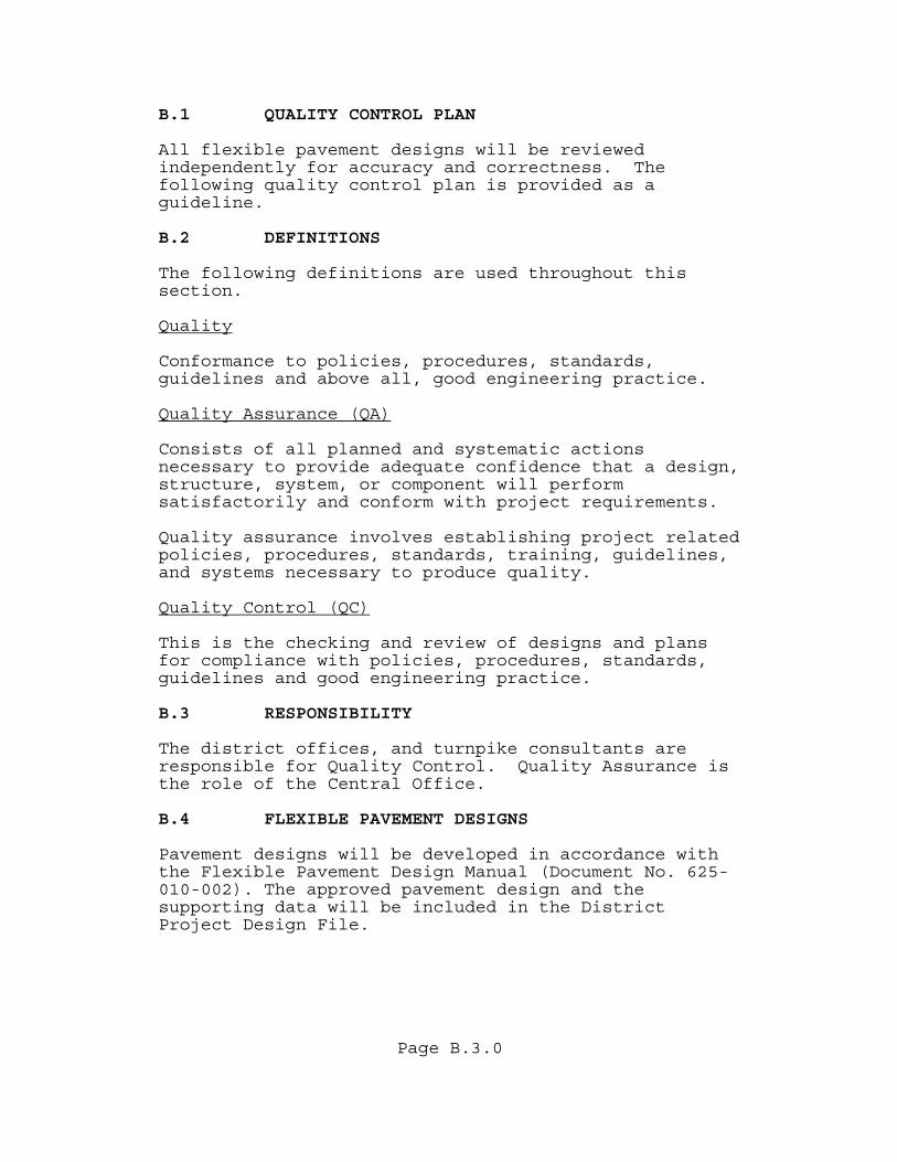
Page B.3.0
B.1 QUALITY CONTROL PLAN All flexible pavement designs will be reviewed independently for accuracy and correctness. The following quality control plan is provided as a guideline. B.2 DEFINITIONS The following definitions are used throughout this section. Quality Conformance to policies, procedures, standards, guidelines and above all, good engineering practice. Quality Assurance (QA) Consists of all planned and systematic actions necessary to provide adequate confidence that a design, structure, system, or component will perform satisfactorily and conform with project requirements. Quality assurance involves establishing project related policies, procedures, standards, training, guidelines, and systems necessary to produce quality. Quality Control (QC) This is the checking and review of designs and plans for compliance with policies, procedures, standards, guidelines and good engineering practice. B.3 RESPONSIBILITY The district offices, and turnpike consultants are responsible for Quality Control. Quality Assurance is the role of the Central Office. B.4 FLEXIBLE PAVEMENT DESIGNS Pavement designs will be developed in accordance with the Flexible Pavement Design Manual (Document No. 625-010-002). The approved pavement design and the supporting data will be included in the District Project Design File.
Page B.4.0
B.4.1 MINIMUM REQUIREMENTS The Pavement Design Package as a minimum will include the following items: • The Pavement Design Summary Sheet will show the
approved pavement design and each Pavement Design Summary Sheet will be signed and sealed by the District Pavement Design Engineer or the designated responsible Pavement Design Engineer. The District Design Engineer will sign for concurrence with the design. The file copy will show Federal Highway Administration (FHWA) approval, if required, for Federal Aid Projects or Certification Acceptance as appropriate.
• Project location and description of the type of work, if not clearly stated on the summary sheet.
• The basis for the pavement design, signed and sealed where required, including if applicable for:
New Construction
- Resilient Modulus (MR). - Material properties used if different
than those in the design manual. - Subgrade stabilization requirements.
Rehabilitation And Lane Widening
- Existing pavement layer information
(layer types, thickness, and condition). - A copy of the Pavement Coring and
Evaluation Report. - Subgrade stabilization requirements. - Leveling and/or overbuild
recommendations. - A copy of the signed and sealed
Nondestructive Testing Report from the State Materials Office.
- A composition report must be requested based on the milling recommendations for all projects involving milling greater than 5000 tons.
Page B.5.0
- Existing cross-slope from design survey and method of correction if required
- The ESALD calculations, signed and certified. This may be either a copy of the report prepared by the Planning Office or calculations using the design computer program. The basis for the input data used for these calculations must be stated.
• Design calculations (including pavement layer
thickness). • Documentation addressing any special features such
as feathering details, cross slope, coordination with adjacent projects, stage construction, drainage considerations, etc.
• Sketch of a possible layer construction sequence, including any
widening and shoulders, to insure constructability.
• A drawing of the final pavement design typical section or an adequate narrative description.
B.4.2 DISTRIBUTION Central Office approval of the pavement design is not required. Designs will be monitored and periodically reviewed, in detail, for quality assurance and for purposes of identifying and improving deficiencies in design policies, procedures, standards and guidelines. For Federal Aid Projects which are for oversight in design, two copies of the approved Pavement Design Summary Sheet and one copy of the supporting documentation, will be forwarded directly to the appropriate Federal Highway Administration (FHWA) Engineer for FHWA concurrence (concurrent with the transmittal to the State Pavement Design Engineer). Only mainline or major elements of a project need formal FHWA pavement design approval. Details such as cross roads and shoulders will be handled as a part of the plans approval process. Do not send these copies to the Central Office for transmittal to FHWA.
Page B.6.0
The District will deal directly with the FHWA to resolve any questions. Central Office Pavement Management will be available for assistance if requested by the District or FHWA. The FHWA will return directly to the District one copy of the summary sheet with signature denoting concurrence. This copy will be filed in the District Project Design file. B.4.3 REVISIONS Changes made subsequent to formal distribution will require that a revised summary sheet be prepared, a copy of which shall be signed and sealed, distributed, and filed for permanent record in the Project Design File. Minor changes may be noted in type or ink on the original Pavement Design Summary Sheet with the responsible Professional Engineer's initials and the date of change. A copy of the revised original should then be signed, dated, sealed and filed for permanent record. Major changes may require that a complete new Pavement Design Summary Sheet be prepared and processed, in which case it shall note that it supersedes a previous design. Copies of revised pavement designs including backup data documenting why the change is being made will be transmitted to the State Pavement Design Engineer and redistributed as appropriate. For skid hazard, intersection improvement, short roadway connectors on bridge replacement projects, and roadway widening projects, the Resilient Modulus, ESALD, and computation of Required Structural Number (SNR) are normally not required. However in all cases, a document describing how the pavement design was developed should be prepared, signed and sealed.
Page B.7.0
B.4.4 DOCUMENTATION The one area of pavement design involving perhaps the greatest liability to the Pavement Design Department is friction course selection. It is highly recommended that the Pavement Design Engineer become thoroughly familiar with the Departments Friction Course Policy. On projects where the policy is not adhered to, the reasons should be clearly documented in the Pavement Design Package. Small projects are not exempt. Every attempt should be made to follow written procedures. Situations will occur where following the pavement design procedure will result in a SNR which cannot be met. This could occur when an overlay is required in a curb and gutter section, or, when an existing cracked or distressed pavement requires rehabilitation, but the Existing Structural Number (SNE) exceeds the Structural Required (SNR). The Pavement Design Engineer will have to exercise engineering judgment on what should be done in these cases. When this occurs, the Pavement Design Engineer is advised to document the project, make special note of the problem, and provide additional explanation as to how the recommended design was developed. Consultation with other engineers (Construction, Drainage, Materials, etc.) is highly recommended and should be noted in the design file. B.5 DISTRICT QUALITY CONTROL The quality control process will include three activities: • The checking and review of pavement designs for
compliance with policies, procedures, standards, guidelines and good engineering practice.
• The checking and review of plans to insure that the
approved pavement designs are correctly incorporated.

Page B.8.0
• Documentation of the Quality Control Process. The Quality Control Process will be carried out by an independent qualified Professional Engineer. As a minimum, the documentation will consist of a copy of the QC Checklist filed with the Pavement Design Package, or a Pavement Design Quality Control File maintained by State Project Number order consisting of: • A copy of the signed and sealed Pavement Design
Summary Sheet. • A copy of the QC Checklist signed by the QC
Engineer. • A sample checklist is attached. B.6 QUALITY ASSURANCE REVIEWS The State Pavement Design Engineer will be responsible for conducting and/or coordinating all pavement related QA activities within each District and the Turnpike. A QA review of District Pavement Design activities will generally be conducted annually. B.7 PAVEMENT DESIGN UPDATES A pavement design review activity by an experienced pavement designer should be scheduled in the project scheduling system on all pavement projects approximately three months prior to shipping plans to Tallahassee. This final review will allow for updating pavement designs and plans for new technologies and pay items that may have been implemented since the original pavement design was prepared. If the pavement evaluation report is over two years old, another field review of the pavement should be conducted to see if the pavement condition has significantly changed. If there is a significant change, a few additional cores may be needed to evaluate crack depths for milling and the pavement design and quantities may need updating to reflect the latest pavement condition.
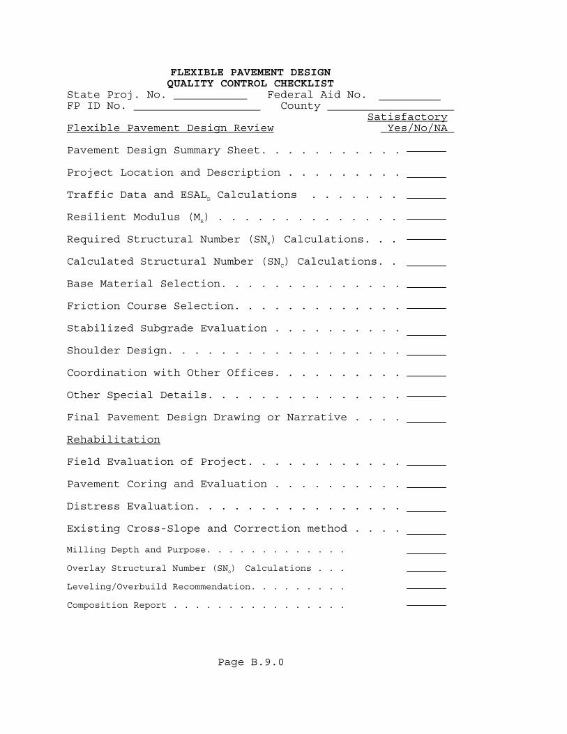
FLEXIBLE PAVEMENT DESIGN QUALITY CONTROL CHECKLIST State Proj. No. Federal Aid No. FP ID No. County SatisfactoryFlexible Pavement Design Review Yes/No/NA
Page B.9.0
Pavement Design Summary Sheet. . . . . . . . . . . Project Location and Description . . . . . . . . . Traffic Data and ESALD Calculations . . . . . . . Resilient Modulus (MR) . . . . . . . . . . . . . . Required Structural Number (SNR) Calculations. . . Calculated Structural Number (SNC) Calculations. . Base Material Selection. . . . . . . . . . . . . . Friction Course Selection. . . . . . . . . . . . . Stabilized Subgrade Evaluation . . . . . . . . . . Shoulder Design. . . . . . . . . . . . . . . . . . Coordination with Other Offices. . . . . . . . . . Other Special Details. . . . . . . . . . . . . . . Final Pavement Design Drawing or Narrative . . . . Rehabilitation Field Evaluation of Project. . . . . . . . . . . . Pavement Coring and Evaluation . . . . . . . . . . Distress Evaluation. . . . . . . . . . . . . . . . Existing Cross-Slope and Correction method . . . . Milling Depth and Purpose. . . . . . . . . . . . . Overlay Structural Number (SNO) Calculations . . . Leveling/Overbuild Recommendation. . . . . . . . . Composition Report . . . . . . . . . . . . . . . .
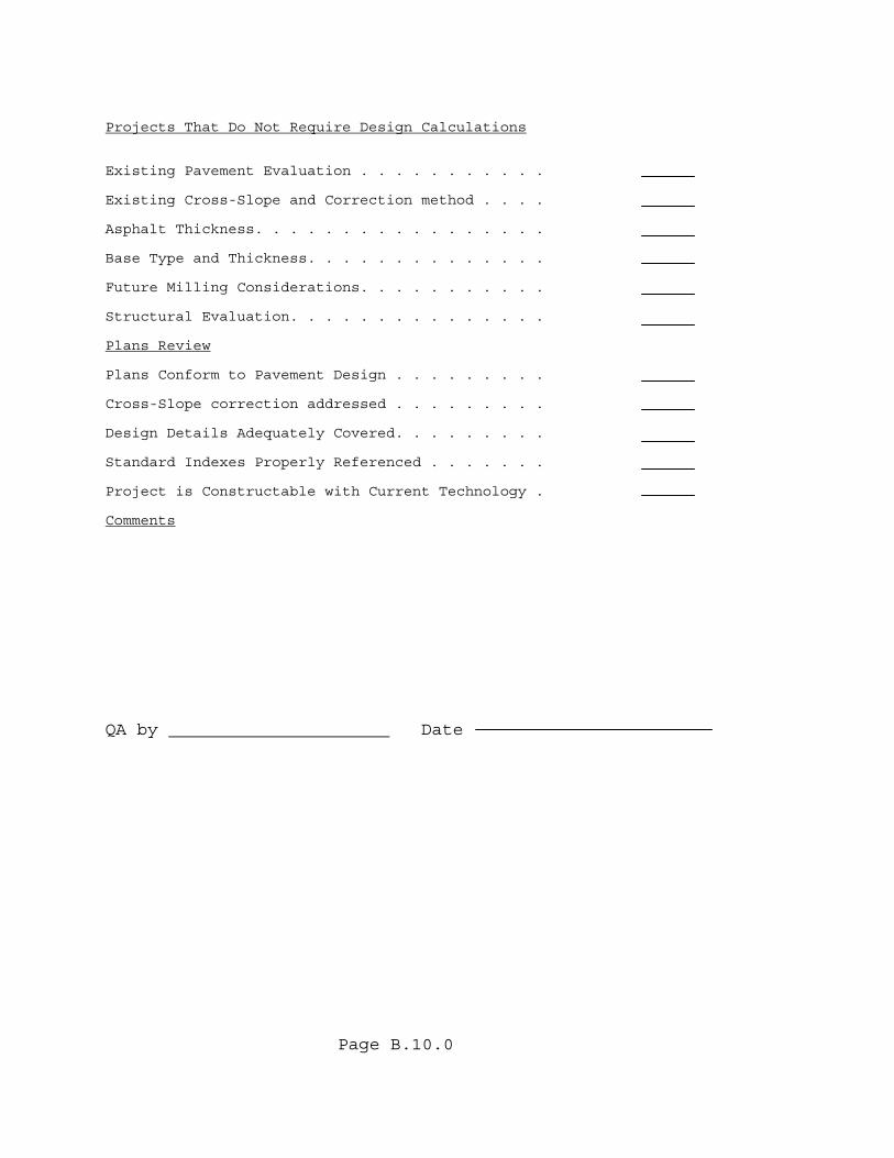
Projects That Do Not Require Design Calculations Existing Pavement Evaluation . . . . . . . . . . .
Page B.10.0
Existing Cross-Slope and Correction method . . . . Asphalt Thickness. . . . . . . . . . . . . . . . . Base Type and Thickness. . . . . . . . . . . . . . Future Milling Considerations. . . . . . . . . . . Structural Evaluation. . . . . . . . . . . . . . . Plans Review Plans Conform to Pavement Design . . . . . . . . . Cross-Slope correction addressed . . . . . . . . . Design Details Adequately Covered. . . . . . . . . Standard Indexes Properly Referenced . . . . . . . Project is Constructable with Current Technology . Comments QA by Date
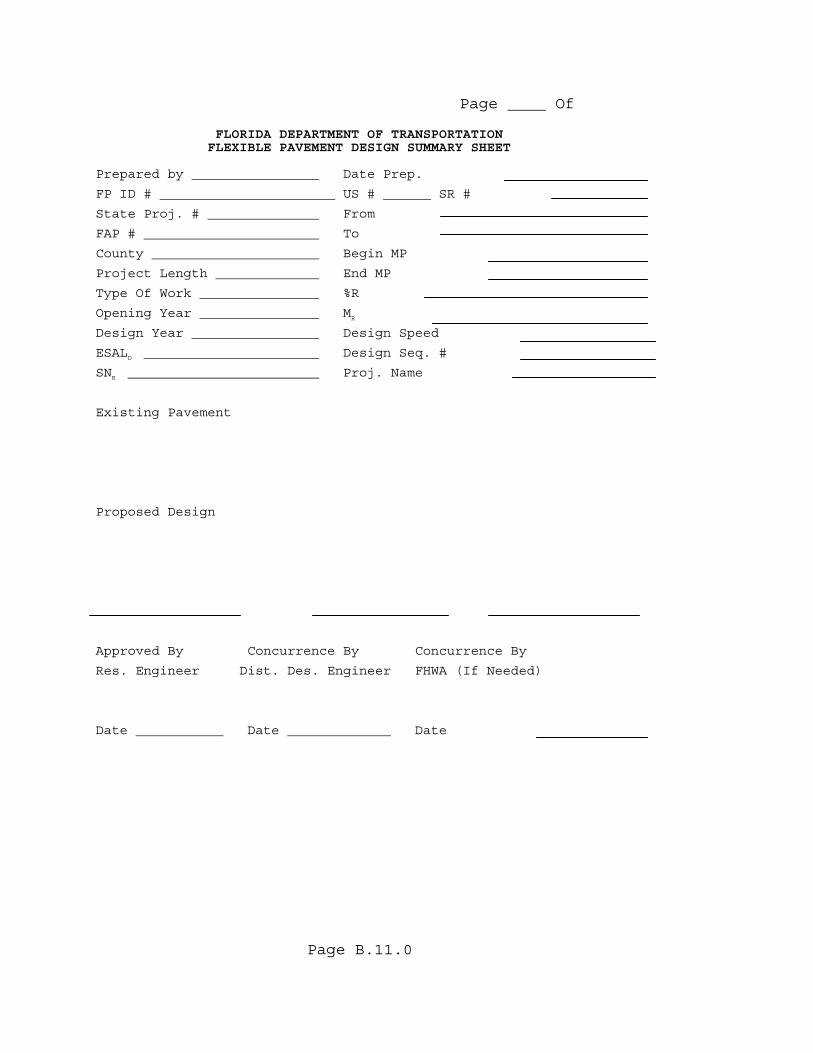
Page Of
Page B.11.0
FLORIDA DEPARTMENT OF TRANSPORTATION FLEXIBLE PAVEMENT DESIGN SUMMARY SHEET Prepared by Date Prep.
FP ID # US # SR #
State Proj. # From
FAP # To
County Begin MP
Project Length End MP
Type Of Work %R
Opening Year MR
Design Year Design Speed
ESALD Design Seq. #
SNR Proj. Name
Existing Pavement
Proposed Design
Approved By Concurrence By Concurrence By
Res. Engineer Dist. Des. Engineer FHWA (If Needed)
Date Date Date

Page B.12.0
(THIS PAGE HAS BEEN LEFT INTENTIONALLY BLANK)
Page C.1.0
APPENDIX C FLEXIBLE PAVEMENT DESIGN ANALYSIS COMPUTER PROGRAM
Page C.2.0
AASHTOWARE DARWin (Design, Analysis and Rehabilitation for Windows) is a computerized release of the pavement design models presented in the AASHTO Guide for the Design of pavement structures.
Page C.3.0
(THIS PAGE HAS BEEN LEFT INTENTIONALLY BLANK)
Page D.1.0
APPENDIX D
ESTIMATING DESIGN 18-KIP(80-KILONEWTON) EQUIVALENT SINGLE AXLE LOADS (ESALD)

Page D.2.0
(THIS PAGE HAS BEEN LEFT INTENTIONALLY BLANK)
Page D.3.0
D.1 BACKGROUND One of the products of the AASHO (American Association Of State Highway Officials) Road Test conducted in Ottowa, Illinois from 1958 to 1960 was a method for relating the relative damage caused by different axle loadings. This evolved into a procedure that permitted the calculation of the accumulated damage caused by mixed vehicle loadings over a pavement design period. The four tire, single axle, carrying 18,000lb 18-kip(80 000 Newtons, 80-kN) Equivalent Single Axle Load or ESALD) was accepted as the base for these calculations. Table D.1 illustrates the relationship of axle weight to damage. A detailed write-up, including tabulated damage factors for single, tandem, and triple axles, is given in Appendix D of the 1993 AASHTO (American Association Of State Highway and Transportation Officials) Guide for Design of Pavement Structures. A procedure for calculating a more precise estimate on the Department's projects can be obtained from the Office of Planning Project Traffic Forecasting Procedure Topic No. 525-030-120 using the Project Traffic Forecasting Handbook. Calculations on Department projects must be signed and certified by the Department's planning section. The following is a simple procedure for estimating ESALD in the design lane. Design periods used in these calculations can be found in the manual. The design lane is the lane where the majority of the trucks can be found. A common example would be a four lane divided highway where most of the trucks would be found in the outside lanes. The basic equation is presented and the variables are defined. Simple input coefficients are tabulated. Several computer programs that perform the necessary computations are available from the Department.
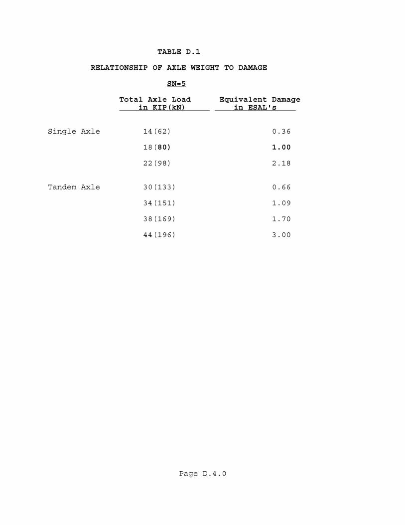
Page D.4.0
TABLE D.1 RELATIONSHIP OF AXLE WEIGHT TO DAMAGE SN=5
Total Axle Load Equivalent Damage in KIP(kN) in ESAL's
Single Axle 14(62) 0.36
18(80) 1.00
22(98) 2.18 Tandem Axle 30(133) 0.66
34(151) 1.09
38(169) 1.70
44(196) 3.00
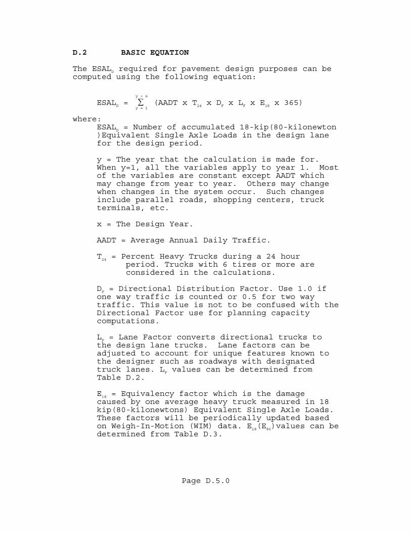
Page D.5.0
D.2 BASIC EQUATION The ESALD required for pavement design purposes can be computed using the following equation:
y = x
ESALD = ∑ (AADT x T24 x DF x LF x E18 x 365) y = 1
where: ESALD = Number of accumulated 18-kip(80-kilonewton )Equivalent Single Axle Loads in the design lane for the design period.
y = The year that the calculation is made for. When y=1, all the variables apply to year 1. Most of the variables are constant except AADT which may change from year to year. Others may change when changes in the system occur. Such changes include parallel roads, shopping centers, truck terminals, etc.
x = The Design Year.
AADT = Average Annual Daily Traffic.
T24 = Percent Heavy Trucks during a 24 hour period. Trucks with 6 tires or more are
considered in the calculations.
DF = Directional Distribution Factor. Use 1.0 if one way traffic is counted or 0.5 for two way traffic. This value is not to be confused with the Directional Factor use for planning capacity computations. LF = Lane Factor converts directional trucks to the design lane trucks. Lane factors can be adjusted to account for unique features known to the designer such as roadways with designated truck lanes. LF values can be determined from Table D.2. E18 = Equivalency factor which is the damage caused by one average heavy truck measured in 18 kip(80-kilonewtons) Equivalent Single Axle Loads. These factors will be periodically updated based on Weigh-In-Motion (WIM) data. E18(E80)values can be determined from Table D.3.
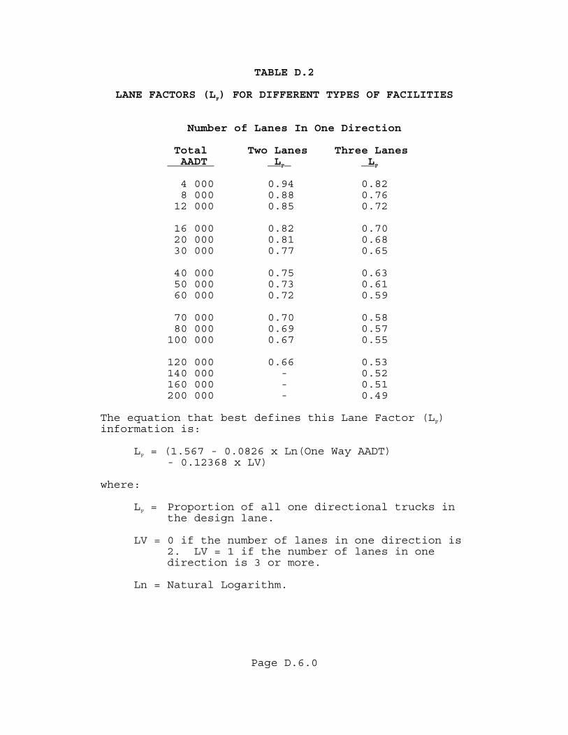
Page D.6.0
TABLE D.2 LANE FACTORS (LF) FOR DIFFERENT TYPES OF FACILITIES
Number of Lanes In One Direction
Total Two Lanes Three Lanes AADT LF LF
4 000 0.94 0.82 8 000 0.88 0.76 12 000 0.85 0.72
16 000 0.82 0.70 20 000 0.81 0.68 30 000 0.77 0.65
40 000 0.75 0.63 50 000 0.73 0.61 60 000 0.72 0.59
70 000 0.70 0.58 80 000 0.69 0.57 100 000 0.67 0.55
120 000 0.66 0.53 140 000 - 0.52 160 000 - 0.51 200 000 - 0.49
The equation that best defines this Lane Factor (LF) information is:
LF = (1.567 - 0.0826 x Ln(One Way AADT) - 0.12368 x LV)
where:
LF = Proportion of all one directional trucks in the design lane.
LV = 0 if the number of lanes in one direction is
2. LV = 1 if the number of lanes in one direction is 3 or more.
Ln = Natural Logarithm.
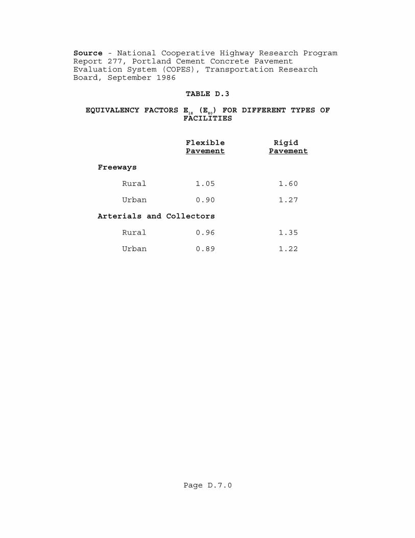
Page D.7.0
Source - National Cooperative Highway Research Program Report 277, Portland Cement Concrete Pavement Evaluation System (COPES), Transportation Research Board, September 1986 TABLE D.3 EQUIVALENCY FACTORS E18 (E80) FOR DIFFERENT TYPES OF FACILITIES
Flexible Rigid Pavement Pavement
Freeways
Rural 1.05 1.60
Urban 0.90 1.27
Arterials and Collectors
Rural 0.96 1.35
Urban 0.89 1.22

Page D.8.0
D.3 SAMPLE PROBLEMS Several sample problems have been provided that illustrate this process. D.3.1 SAMPLE PROBLEM #1 The District Planning Engineer has provided the following information about a high volume, urban, arterial, four lane divided two way project that will open in the year 2005. The Pavement Type Selection Process indicates that the best alternative is flexible pavement. GIVEN: The following input is provided. Note that other facilities within the urban area become available in the year 2013 thus causing the traffic assignment (AADT) to drop and T24 to change.
T24 = 12% 2005 Estimated AADT = 12,000 2013 Estimated AADT = 16,000
T24 = 8% 2014 Estimated AADT = 34,000 2025 Estimated AADT = 56,000
DATA: The following data can be determined from information and tables provided.
DF = 0.50 (for two way traffic) E18 = 0.89 (from Table D.3)
LF = Determined using the equation from Table D.2
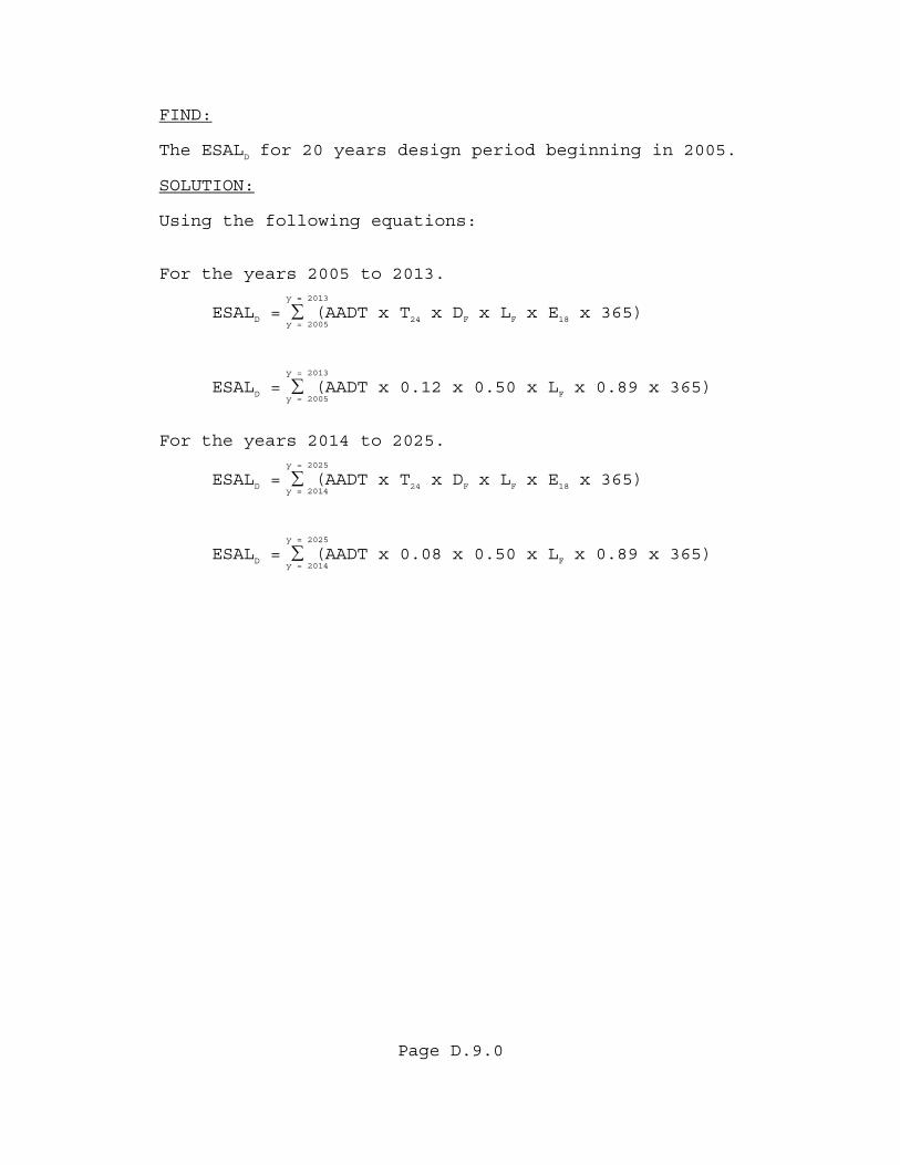
Page D.9.0
FIND: The ESALD for 20 years design period beginning in 2005. SOLUTION: Using the following equations: For the years 2005 to 2013.
y = 2013
ESALD = ∑ (AADT x T24 x DF x LF x E18 x 365) y = 2005
y = 2013
ESALD = ∑ (AADT x 0.12 x 0.50 x LF x 0.89 x 365) y = 2005
For the years 2014 to 2025.
y = 2025
ESALD = ∑ (AADT x T24 x DF x LF x E18 x 365) y = 2014
y = 2025
ESALD = ∑ (AADT x 0.08 x 0.50 x LF x 0.89 x 365) y = 2014

Page D.10.0
Calculating:
Annual Accumulated Year AADT LF ESAL* ESAL
2005 12 000 0.85 198 800 198 800 2006 12 500 0.84 204 700 403 500 2007 13 000 0.84 212 800 616 300 2008 13 500 0.84 221 000 837 300
2009 14 000 0.84 229 200 1 066 500 2010 14 500 0.83 234 600 1 301 100 2011 15 000 0.83 242 700 1 543 800 2012 15 500 0.83 250 800 1 794 600
2013 16 000 0.82 255 700 2 050 300 2014 34 000 0.76 335 800 2 386 100 2015 36 000 0.76 355 500 2 741 600 2016 38 000 0.75 370 300 3 111 900
2017 40 000 0.75 389 800 3 501 700 2018 42 000 0.75 409 300 3 911 000 2019 44 000 0.74 423 100 4 334 100 2020 46 000 0.74 442 300 4 776 400
2021 48 000 0.73 455 300 5 231 700 2022 50 000 0.73 474 300 5 706 000 2023 52 000 0.73 493 300 6 199 300 2024 54 000 0.72 505 200 6 704 500 2025 56 000 0.72 523 900 7 228 400
* Values are rounded for simplicity.
CONCLUSION: Note that the 20 years accumulated value (ESALD) is 6,704,500 ESALs or 7,000,000 ESALs.
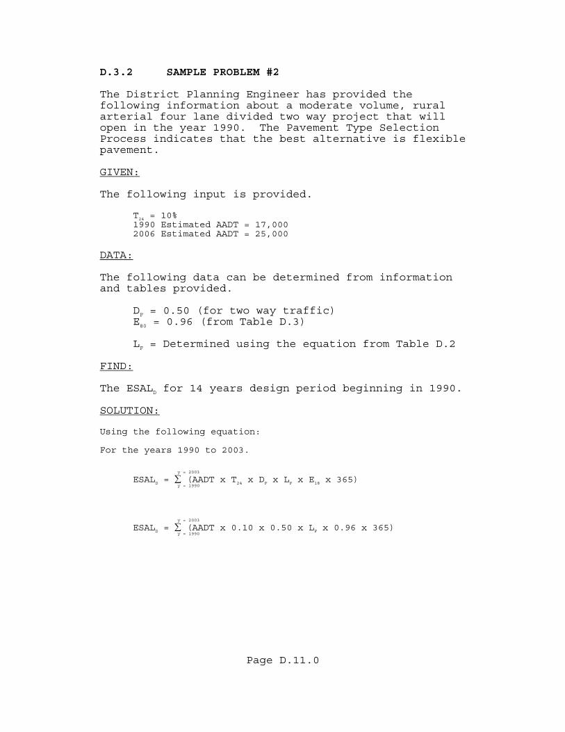
Page D.11.0
D.3.2 SAMPLE PROBLEM #2 The District Planning Engineer has provided the following information about a moderate volume, rural arterial four lane divided two way project that will open in the year 1990. The Pavement Type Selection Process indicates that the best alternative is flexible pavement. GIVEN: The following input is provided.
T = 10% 24
1990 Estimated AADT = 17,000 2006 Estimated AADT = 25,000
DATA: The following data can be determined from information and tables provided.
DF = 0.50 (for two way traffic) E80 = 0.96 (from Table D.3)
LF = Determined using the equation from Table D.2
FIND: The ESALD for 14 years design period beginning in 1990. SOLUTION: Using the following equation: For the years 1990 to 2003.
y = 2003
ESALD = ∑ (AADT x T24 x DF x LF x E18 x 365) y = 1990
y = 2003
ESALD = ∑ (AADT x 0.10 x 0.50 x LF x 0.96 x 365) y = 1990
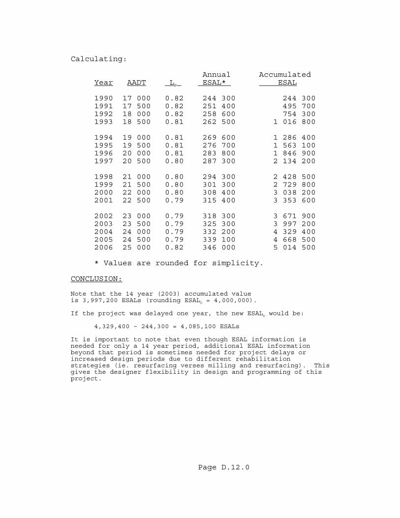
Page D.12.0
Calculating:
Annual Accumulated Year AADT LF ESAL* ESAL
1990 17 000 0.82 244 300 244 300 1991 17 500 0.82 251 400 495 700 1992 18 000 0.82 258 600 754 300 1993 18 500 0.81 262 500 1 016 800
1994 19 000 0.81 269 600 1 286 400 1995 19 500 0.81 276 700 1 563 100 1996 20 000 0.81 283 800 1 846 900 1997 20 500 0.80 287 300 2 134 200
1998 21 000 0.80 294 300 2 428 500 1999 21 500 0.80 301 300 2 729 800 2000 22 000 0.80 308 400 3 038 200 2001 22 500 0.79 315 400 3 353 600
2002 23 000 0.79 318 300 3 671 900 2003 23 500 0.79 325 300 3 997 200 2004 24 000 0.79 332 200 4 329 400 2005 24 500 0.79 339 100 4 668 500 2006 25 000 0.82 346 000 5 014 500
* Values are rounded for simplicity.
CONCLUSION: Note that the 14 year (2003) accumulated value is 3,997,200 ESALs (rounding ESALD = 4,000,000). If the project was delayed one year, the new ESALD would be:
4,329,400 – 244,300 = 4,085,100 ESALs It is important to note that even though ESAL information is needed for only a 14 year period, additional ESAL information beyond that period is sometimes needed for project delays or increased design periods due to different rehabilitation strategies (ie. resurfacing verses milling and resurfacing). This gives the designer flexibility in design and programming of this project.
Page E.1.0
APPENDIX E
RELATIONSHIP BETWEEN RESILIENT MODULUS(Mr) AND LIMEROCK BEARING RATIO(LBR)