flexible joints for marine risers
TRANSCRIPT
United States Patent [191 one
[11] 4,068,868 [45] Jan. 17, 1978
[54] FLEXIBLE JOINTS FOR MARINE RISERS
Juergen H. Ohrt, Kreis, Rensdburg, Germany Vetco Offshore Industries, Inc., Ventura, Calif.
[21] Appl. No.: 609,584
[75] Inventor:
[73] Assignee:
[22] Filed: Sept. 2, 1975
[51] Int. Cl.2 ............................................ .. F16L 27/04 [52] US. Cl. ............................... .. 285/263; 285/223 [58] Field of Search ............. .. 285/166, 167, 223, 261,
285/263, 276, 280, 281, 51
[56] References Cited U.S. PATENT DOCUMENTrS~w~~~~~ ' -
3,504,903 4/1970 Irwin ........................ .. 29/ 148.4 A X 3,680,895 8/1972 Herbert et al. . ....... .. 285/223
3,712,645 l/ 1973 Herter ....... .. .. 285/ 167 X
3,848,899 11/1974 Smith ................................. .. 285/263
Primary Examiner——Wayne L. Shedd Attorney, Agent, or Firm-Subkow and Kriegel
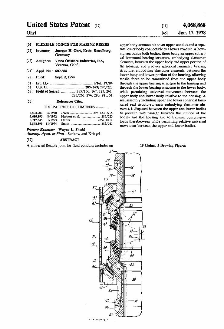
upper body connectible to an upper conduit and a sepa rate lower body connectible to a lower conduit. A hous ing surrounds both bodies, there being an upper spheri cal laminated bearing structure, embodying elastomer elements, between the upper body and upper portion of the housing, and a lower spherical laminated bearing structure, embodying elastomer elements, between the lower body and lower portion of the housing, allowing tensile force to be transmitted from the upper body through the upper bearing structure to the housing and through the lower bearing structure to the lower body, while permitting universal movement between the upper body and lower body relative to the housing. A seal assembly including upper and lower spherical lami nated seal structures, each embodying elastomer ele ments, is disposed between the upper and lower bodies to prevent fluid passage between the interior of the bodies and the housing and to transmit compressive loads therebetween while permitting relative universal movement between the upper and lower bodies.
[57] ABSTRACT .
A universal ?exible joint for ?uid conduits includes an . 19 Claims, 5 Drawing Figures
11
17 . 1.9
80
13 25
Z 7__‘ //'/
a2» ; ‘
47——-p '- 83
s 55 ‘ ' 92
64 66 8 52
g Q... 7 < 54
88 1- a4
1 94
45-; ' a a?‘ I ‘ 31
-, 1
., I 39
I 1 a . 3 a! i
45 -’——37
46
45' _,\j


US. Patant Jan. 17, 1978 Sheet 2.of3 4,068,88
iiéras $6,
17
19
.11
g; 55 2 I 1535 27
26
7
28


4,068,868 1
FLEXIBLE JOINTS FOR MARINE RISERS This invention relates to ?exible joints, and more
particularly to tubular ?exible joints for use with marine risers and associated equipment used in the drilling of subsea well bores.
In the drilling of offshore well bores, a marine riser is provided which extends from a surface drilling vessel to the region of the ocean ?oor. One or more ?exible joints are incorporated in the marine riser to reduce bending stresses between the upper and lower portions of the riser. These ?exible joints must provide a seal preventing leakage of ?uid from the interior of the joint to the sea water externally thereof, which would other wise occur because of the differential pressure within the joint arising from the difference in speci?c gravity of the drilling mud within the riser and the sea water externally of the riser. Moreover, a substantial portion of the weight of the marine riser is offset by applying tension to it. This tensile force or pull is also transmitted through the ?exible joint. As the water depth increases in which the drilling operation is being performed, the differential pressure within the riser and the amount of the external pull imposed on the riser increases.
Existing ?exible joints used in connection with ma rine risers have been found to be unsuitable for in creased water depths because of the dif?culty in sealing the joint against leakage due to the high differential pressure between the drilling mud within the riser and the sea water externally thereof. In some joints, the high _ external pull on the riser introduces friction which re stricts the relative movement between the joint parts, and causes wear which eventually will result in joint leakage. A balancing pressure has been provided to compensate for the high tensile force or pull imposed on the joint and for the high separating forces due to the high pressure differential, such as proposed in US. Pat. No. 3,746,372, but the required pressure becomes greater than the control pressure normally available when the joint is disposed in greatly increased water depths. A ?exible joint is disclosed in US. Pat. No. 3,680,895,
in which laminated bearings are provided between the upper and lower body members of the joint for trans mitting stresses therebetween, which also function to seal the joint against leakage that could result from the high differential pressure existing within the marine riser and joint. In the joints disclosed in the patent, internal ?uid pressure enters the housing through which the bearing loads are transmitted, and this high pressure of the ?uid acts on the bearings and puts additional load on them, which necessarily must be dimensioned to withstand such loads. Moreover, compressive loads imposed on the joint disclosed in FIG. 4 of US. Pat. No. 3,680,895 is transmitted through an intervening member, which tends to collapse under high compres sive loads, such compressive loads also introducing undesired friction between the upper and lower body members and the intervening part referred to.
In general, the present invention embodies ?ex joints of the general type disclosed in US. Pat. No. 3,680,895, but in which the bearing members and the seal assembly are separate from one another. The bearing members and seal assembly comprise alternate layers or lamina tions of rigid shims and elastomeric members, the bear ings being surrounded by a housing structure which serves as the intervening agency for transmitting the axial load between the upper body portion of the joint
20
25
45
60
65
2 and the lower body portion of the joint, while permit ting ?exing of the upper and lower bodies with respect to each other. The seal assembly is disposed between the confronting ends of the upper and lower bodies themselves. The bearing assemblies and seal assemblies are held in appropriate assembled relation by the hous ing, which imposes a preload or compression on the bearing assemblies and seal assemblies. The spring rate of the seal assemblies is much lower than the spring rate of the bearing assemblies, so that the preloading of the entire assembly creates a greater de?ection in the seal assembly than in the bearing assembly, causing the seal assembly to always remain in compression despite the fact that the tensile pull on the joint may increase, which tends to increase the distance of the upper body from the lower body. Since the seal assembly always remain in compression, assurance is had against leakage of the ?exible joint. Moreover, the seal assembly serves to transmit compressive loads from one body to the other, eliminating the need for such loads to be trans mitted through the surrounding housing. However, tensile loads are transmitted through the bearing assem blies and the housing. Despite variations in the axial loads imposed on the assembly, the laminated bearing structures and the laminated seal assembly structures always remain under a preload compression, with the lower spring rate of the seal assembly insuring the main tenance of such compression and the prevention of leaks between the interior of the joint and its exterior.
This invention possesses many other advantages, and has other purposes which may be made more clearly apparent from a consideration of several forms in which it may be embodied. Such forms are shown in the draw ings accompanying and forming part of the present speci?cation. These forms will now be described in detail for the purpose of illustrating the general princi ples of the invention; but it is to be understood that such detailed description is not to be taken in a limiting sense.
Referring to the drawings: FIG. 1 is a side elevational view of a ?exible joint
incorporated within a marine riser conductor; FIG. 2 is an enlarged side elevational view and longi
tudinal section through the marine riser disclosed in FIG. 1; FIG. 3 is a further enlarged fragmentary longitudinal
section through a portion of the lower bearing assem bly;
FIG. 4 is a quarter longitudinal section, correspond ing to FIG. 2, through another embodiment of the in vention; and FIG. 5 is a quarter longitudinal section, correspond
ing to FIG. 2, through yet another speci?c form of the invention. As illustrated in the drawings, a ?exible joint 10 is
connected to the lower end of an upper marine riser section 11, and to the upper end of a lower marine section 12, or other subsea member, such as a blowout preventer stack. The marine riser itself extends up wardly to a platform or drilling vessel (not shown) ?oating in a body of water, the major portion of the entire weight of the marine riser being supported by a suitable riser tensioning apparatus (not shown) mounted on the vessel, in a known manner. The upper riser or tubular section 11 is suitably cou
pled to the upper tubular body 13 of the ?exible joint. As shown, the upper section has a lower external ?ange 14 confronting a companion external ?ange 15 on the upper body, a suitable clamp 16 of a known type engag

4,068,868 3
ing both ?anges, forcing and holding them toward one another, and compressing a seal ring or gasket 17 be tween the lower ?ange 14 and the upper end of a re tainer member 18 disposed within the upper body and having an external ?ange 19 seating against a shoulder 20 in the upper body. A suitable seal ring 21 in the upper body engages the periphery of the retainer 18 to prevent ?uid leakage therebetween. The lower end of the re tai‘ner engages a wear bushing 22 which, in turn, is disposed within the upper portion of another wear bushing 23 mounted in a circumferential groove 24 in the upper body. The upper body 13 extends freely through a bore 25a
within an upper member 25 of an outer housing 26. The upper member is secured by a plurality of circumferen tially spaced screws 27 to a housing sleeve 28, the lower end of which is secured by circumferentially spaced screws 29 to a lower member 30 of the housing. The housing itself encloses both the upper body 13 and a lower body 31, the latter extending through an axial bore 32 in the lower housing member. The peripheral portion 33 of the lower body that extends through the lower housing member 30 has a substantially smaller diameter than the inside diameter of the bore 32, in order to permit relative tilting of the lower body 31 relative to the housing 26, as described hereinbelow. Similarly, the upper body 13 has a reduced diameter peripheral portion 33 extending through the axial bore 25a, which is of substantially smaller diameter than the internal diameter of the bore, to permit the upper body 13 to tilt universally in all directions with respect to the housing. For the purposes of preventing substances of large size from entering the upper bore 25a, a suitable shield 35, which may be made of a plurality of sections suitably secured together, rests upon the upper member 25 and projects across the space between the wall of the bore 25a and the upper body. This shield can shift or slide laterally on the upper housing member 25 in re sponse to movement of the upper body 13 relative to the housing 26. A retainer 36 is also mounted within the lower body
31 with its ?ange 37 engaging a downwardly facing body seat 38, this retainer engaging a wear bushing 39 thereabove disposed within another wear bushing 40 mounted within a circumferential groove 41 in the lower body. A seal ring 42 in the lower body sealingly engages the retainer 36 to prevent leakage of ?uid be tween the retainer and body. A seal ring or gasket 43 is clamped between the lower riser section or blowout preventer stack 12 by suitable clamps 44 embracing the opposed ?anges 45, 46 on the lower body 31 and the lower riser section. The upper and lower clamps are omitted from FIGS. 2, 4 and 5 in the interest of clarity. The tensile force imposed upon the marine riser is
transmitted from the upper body 13 to the housing 26 through an upper bearing assembly 47. Similarly, the tensile force is transmitted from the housing to the lower body 31 through a lower bearing assembly 48. As described hereinbelow, both of these assemblies are laminated structures to not only transmit axial forces between the bodies 13, 31 and the housing 26, but to permit relative tilting in all directions of the bodies with respect to the housing and of the upper and lower bod ies with repect to one another.
Diposed between the bodies 13, 31 is a seal assembly 50 to prevent ?uid leakage between the interior of the ?exible joint and the exterior of the assembly disposed within the housing 26. This seal assembly includes an
15
20
25
30
35
40
45
55
60
65
4 intermediate body 51 and an upper seal structure 52 between the intermediate body and the lower end 53 of the upper body 13. Similarly, the seal assembly includes a lower seal structure 54 between the intermediate body and the upper end 55 of the lower body 31. These struc tures 52, 54 are also laminated and are capable of per mitting relative ?exing or tilting in all directions of the upper and lower bodies 13, 31 with respect to the inter mediate body 51 while maintaining the integrity of the seal assembly. The upper and lower bearing assemblies 47, 48 are the
same, being disposed opposite to one another. They are each fabricated with alternate layers of rigid segments or annuli 56 (see FIG. 3), such as steel or fabric, which may be woven nylon or glass ?bers, and elastomeric segments or annuli 57, such as natural or synthetic rub ber, the rigid layers being of substantially less thickness than the elastomer layers. Speci?cally, the segmental layers 56, 57 are of substantially spherical shape, with the outermost layers engaging companion substantially concave spherical shape surfaces 58 on the upper and lower housing members 25, 30 and the innermost layers bearing against substantially convex spherical bearing surfaces 59 on the upper and lower bodies 13, 31 dis posed within the housing 26. If the outermost and inner most layers of each bearing assembly are made of elasto meric materials 57, such layers are secured, as by vulca nizing, to the surfaces 58, 59 of the housing members and bodies against which they bear, the elastomeric and rigid layers 57, 56 also being suitably secured to one another, as by vulcanization, If the outermost and inner most layers are rigid, separate seal elements (not shown) are provided between such rigid elements and their confronting surfaces 58, 59 on the end housing members and bodies 13, 31, which are bonded against the metallic surfaces of the bodies and end housing members.
Similarly, the upper and lower seal structures 52, 54 oppose one another, and may be duplicates of one an other. Essentially, they are the same in construction as the bearing assemblies 47, 48 and are of generally spher ical shape. They consist of alternate layers of rigid spherical segments or annuli 56, made of steel or fabric, such as woven nylon or glass ?bers, with intervening elastomeric spherical segments or annuli 57, which are much thicker than the rigid layers. The outer elastomer layer 57 of each seal structure is suitably secured, as by vulcanizing, to the confronting concave inner end sur face 53 of its companion body 13 or 31; whereas, the opposite elastomer layer 57 is vulcanized to the convex surface 60 of the intermediate body 51. A short circum ferential skirt 61 may extend from each body around the exterior of its associated seal structure, which is also true of intermediate body skirts 62 that extend around the opposite ends of the seal structures, as assurance of further retaining each seal structure 52, 54 in place. The upper substantially spherical bearing assembly
layers 56, 57 and the concave and convex surfaces 58, 59 that they engage have a common center 63, as indicated by the radial line 64 disclosed in FIG. 2, this center being below the center 65 of the entire ?exible joint. The spherical seal surfaces 53, 60 and the spherical seal layers 56, 57 have the same common center 63, as indi cated by the radial line 64a. The center 66 of the spheri cal surfaces 58, 59 on the lower end housing member 30 and body 31, and their intervening bearing assembly segments 56, 57, and also of the concave surface 55 on the lower body and opposed convex surface 60 on the intermediate body 51, and the seal structure segments

4,068,868 5
56, 57 disposed therebetween is above the center 65 of the ?exible joint unit, all of these surfaces and layers having a common center, as indicated by the radial lines 67, 67a. In effect, the radial lines 64, 64a and 67, 67a for developing the spherical surfaces overlap or cross one another, being drawn from overlapping upper and lower centers 66, 63, which enables the entire ?exible joint to be made much shorter in length than if all of the spherical surfaces of the ?exible joint were developed from a common center, such as 65. Upon assembly of the ?exible joint, the end housing
members 25, 30 are secured to the surrounding housing sleeve 28 by the screws 27. As a result of tightening the screws, the upper and lower seal structures 52, 54 and the upper and lower bearing assemblies 47, 48 are placed under compression, the elastomeric spherical segments 57 being compressed and functioning as springs to retain the integrity of each structure and assembly. The seal structures have a substantially lower spring rate than the spring rate of the bearing assem blies, which insures that the laminations of the seal structures will remain in sealed relation to each other and to the upper and lower bodies as the axial load, such as the tensile force imposed upon the upper portion of the marine riser, increases and decreases. This tensile load is transmitted directly from the upper body 13 through the upper bearing assembly 47 to the housing structure 26, and from the housing structure through the lower bearing assembly 48 to the lower body 31, without such load being imposed upon the seal assem bly 50. An increase in the tensile load, for example, will compress the high rate spring upper bearing assembly 47 and will decrease the compressive force on the seal assembly 50. However, because of the seal assembly structures having a lower spring rate than the bearing assemblies, the elastomer layers 57 of the seal structures will expand sufficiently to maintain the integrity of the seal structures and prevent ?uid leakage between the interior of the tubular ?exible joint and the exterior of the seal assemblies and bearing assemblies. In this con nection, it is to be noted that the housing sleeve 28 has openings 70 therein so that the interior and exterior of the housing are subject to the same hydrostatic heads of ?uid of the surrounding sea or ocean water environ ment. The ?uid pressure within the riser ?exible joint is not imposed upon the housing. In the event the joint is subjected to compressive loads, such loads are transmit ted from the upper body 13 through the seal assembly 50 to the lower body 31, without being transmitted through the upper and lower bearing assemblies 47, 48 and the outer housing structure 50. With the ?exible joint illustrated and described, the.
upper body 13 can tilt in all directions with respect to the housing 26, and the housing can tilt in all directions with respect to the lower body 31, with the result that the two bodies 13, 31 can tilt in all directions with re spect to each other to a substantial degree, which, for example, may be as much as a 20° included angle. Since the rubber or other elastomeric layers 57, which are permanently bonded to the intervening rigid layers 56,‘ have a relatively low shear modulus, the adjacent rigid layers can move very easily in relation to each other, making the total movement of each bearing assembly or seal structure the sum of the movement of the individual layers. Despite the substantial relative angular move ment of the seal structures 52, 54 with respect to the upper and lower bodies 13, 31 and‘ the intermediate body 51, the entire seal assembly 50 prevents ?uid 'leak
10
25
30
35
40
45
50
55
60
65
6 age over the full range of tilting movement of the upper and lower bodies with respect to each other.
In the embodiment of the invention disclosed in FIG. 4, the bearing assembly and seal assembly structures have a common center 80, as indicated by the radial lines 81. There is a speci?c difference in the bearing assembly and seal assembly structures. Each bearing assembly has an outer metallic bearing ring 82 bearing against each outer end housing member 25, 30 and an inner metallic bearing ring 83 bearing against each body member 13, 31, the laminated rigid and elastomer spher ical segments 56, 57 being bonded to each other and to the inner and outer rings 82, 83. With respect to the seal assembly, an outer metallic ring 84 bears against the inner end of each body 13, 31 and an intermediate body 51a is suitably secured, as by vulcanizing, to the inner layer of each seal structure 52, 54. To prevent leakage between the outer seal member 84 and the bodies 13, 31, a suitable elastomer seal ring 85 is carried by each body, engaging a companion seal surface of the outer ring 84. The radial line overlapping spherical relationship
disclosed in FIG. 2 not only makes the ?exible joint 10 more compact, but also places the bearing assemblies 47, 48 and seal structures 52, 54 in a position in which the axial loads are transmitted in compression through the bearing and seal structures to a greater extent that the laminated bearing and seal structures illustrated in FIG. 4, which are developed about a common center 80. As disclosed in FIG. 4, the loads are transmitted through the laminated structures to a greater extent in shear, as a result of axial movement of the bodies 13, 31 relative to one another and of the universal tilting of the bodies with respect to each other. The rigid members 56 can shift readily with respect to each other in transmit ting shear through the laminated assemblies because of the ?exible characteristics of the elastomeric layers 57.
In the embodiment of the invention disclosed in FIG. 5, the ?exible joint is substantially the same as disclosed in FIG. 4, except that the centers 90, 91 about which the upper and lower laminated structures and spherical and seal surfaces are developed are spaced from one an other. As disclosed, the radii of curvature 92 for the upper bearing assembly and the upper seal structure extend from a single center 90, which is spaced up wardly from the common center 93 of the ?exible joint unit. Similarly, the radii of curvature 94 of the spherical surfaces of the lower bearing assembly and the lower seal structure extend from a single center 91 which is spaced below the common center 94 of the ?exible joint unit. With this arrangement, the laminated elements 56, 57 have a greater amount of shear stress imposed upon them than the ?exible joint disclosed in FIG. 4, as a resultof the tilting of the upper body 13 relative to the lower body 31. Because of the spherical surfaces in volved, the tilting action is universal in that it can occur in all directions.
In the various forms of the invention, reference has been made. to spherical surfaces. However, these sur faces need not be spherical in a true geometric sense, since they could be made somewhat conical and an operable ?exible joint provided because of the elasto meric properties present in the bearing assemblies and the seal structures.
‘'1 claim: 1. A ?exible joint through which ?uid can be con
ducted comprising: ?rst and second bodies having a ' ?uid passage therethrough and adapted to be disposed in a tubular string, a housing structure surrounding said

4,068,868 7
bodies, a ?rst bearing assembly between and engaging said ?rst body and housing structure for transmitting loads therebetween while permitting relative tilting between said ?rst body and housing structure, a second bearing assembly between and engaging said second body and housing structure for transmitting loads there between while permitting relative tilting between said second body and housing structure, and a seal assembly between and engaging said bodies to prevent ?uid ?ow between said passage and the exterior of said bodies, said seal assembly including means for transmitting axial loads between said bodies while permitting relative tilting between said bodies, each of said bearing assem blies including laminations of alternate layers of rigid material and yieldable material and secured to a body and housing structure, said seal assembly including a third body between said ?rst and second bodies and laminations of alternate layers of rigid material and yieldable material between and secured to said third body and each of said ?rst and second bodies, said hous ing structure including means for compressing said ?rst and second bearing assemblies between said housing structure and ?rst and second bodies and said seal as sembly laminations between said third body and said ?rst and second bodies.
2. A ?exible joint as de?ned in claim 1, said seal as sembly laminations being constructed and arranged to have a lower spring rate than said bearing assembly laminations.
3. A ?exible joint as de?ned in claim 1; said yieldable material of each bearing assembly being an elastomeric material, said yieldable material of said seal assembly being an elastomeric material.
4. A ?exible joint as de?ned in claim 3; said seal as sembly laminations being constructed and arranged to have a lower spring rate than said bearing assembly laminations.
5. A ?exible joint as de?ned in claim 1; said housing structure having passage means for establishing commu nication between the exterior and interior of said struc ture.
6. A ?exible joint through which ?uid can be con ducted comprising: ?rst and second bodies having a ?uid passage therethrough and adapted to be disposed in a tubular string, said ?rst and second bodies having ?rst and second generally spherical bearing surfaces, respectively, and also ?rst and second generally spherie cal seal surfaces, respectively, a housing structure sur rounding said bodies and having spaced generally spherical ?rst and second bearing surfaces confronting said bearing surfaces on said ?rst and second bodies, respectively, a ?rst bearing assembly between and en gaging said ?rst body bearing surface and said ?rst bearing surface on said housing structure, a second bearing assembly between and engaging said second body bearing surface and said second bearing surface on said housing structure, a third body between said ?rst and second bodies and having generally spherical ?rst and second seal surfaces confronting said ?rst and sec ond body seal surfaces, respectively, ?rst and second seal structures between and engaging said third body ?rst and second seal surfaces, respectively, and said ?rst and second body seal surfaces, respectively, said hous ing structure including means for compressing said ?rst and second bearing assemblies between said housing structure and ?rst and second bodies and said seal struc tures between said third body and said ?rst and second bodies, each of said bearing assemblies including gener ally spherical laminations of alternate layers of rigid material and yieldable material and secured to a ?rst or second body and said housing structure, each of said
20
25
45
55
65
8 seal structures including generally spherical laminations of alternate layers of rigid material and yieldable mate rial secured to said third body and each of said ?rst and second bodies.
7. A ?exible joint as de?ned in claim 6; said seal struc tures being constructed and arranged to have a lower spring rate than said bearing assemblies.
8. A ?exible joint as de?ned in claim 6; said yieldable material of each bearing assembly being an elastomeric material, said yieldable material of said seal structures being an elastomeric material.
9. A ?exible joint as de?ned in claim 8; said seal struc ture being constructed and arranged to have a lower spring rate than said bearing assemblies. _
10. A ?exible joint as de?ned in claim 6; said housing structure having passage means for establishing commu nication between the exterior and interior of said struc ture.
11. A ?exible joint as de?ned in claim 6; said ?rst bearing surfaces and bearing assembly laminations be tween said ?rst bearing surfaces, said ?rst seal surfaces and seal structure laminations between said ?rst seal surfaces having radii of curvature extending from a ?rst common center, said second bearing surfaces and bear ing assembly laminations between said second bearing surfaces, second seal surfaces and seal structure lamina tions between said second seal surfaces having radii of curvature extending from a second common center spaced axially from said ?rst common center.
12. A ?exible joint as de?ned in claim 11; said com mon centers being so located with respect to each other that radii drawn from said ?rst common center to. said ?rst bearing surfaces, ?rst seal surfaces, laminations between said ?rst bearing surfaces and laminations be tween said ?rst seal surfaces cross radii drawn from said second common center to said second bearing surfaces, second seal surfaces, laminations between said second bearing surfaces and laminations between said second seal surfaces.
13. A ?exible joint as de?ned in claim 12; said seal structures being constructed and arranged to have a lower spring rate than said bearing assemblies.
14. A ?exible joint as de?ned in claim 13; said yield able material of said bearing assembly laminations and yieldable material of said seal structure laminations being elastomeric. .
15. A ?exible joint as de?ned in claim 11; said com mon centers being so located with respect to each other .that radii drawn from ‘said ?rst common center to said ?rst bearing surfaces, ?rst seal surfaces, laminations between said ?rst bearing surfaces and laminations be tween said ?rst seal surfaces are spaced in their entirety from radii drawn from said second common center to said second bearing surfaces, second seal surfaces, lami nations between said second bearing surfaces and lami nations between said second seal surfaces.
16. A ?exible joint as de?ned in claim 15; said seal structures being constructed and arranged to have a lower spring rate than said bearing assemblies.
17. A ?exible joint as de?ned in claim 16; said yield able material of said bearing assembly laminations and yieldable material of said seal structure laminations being elastomeric.
18. A ?exible joint as de?ned in claim 11;,said seal structures being constructed and arranged to have a lower spring rate than said bearing assemblies.
19. A ?exible joint as de?ned in claim 18; said yield able material of said bearing assembly laminations and yieldable material of said seal structure laminations being elastomeric.
* * * * *