flexible firsers for tension leg platform … · 1 flexible risers for tension leg platform n....
TRANSCRIPT
1
FLEXIBLE RISERS FOR TENSION LEG PLATFORM
N. Ismail Wellstream Corporation
Panama City, Florida
ABSTRACT
A review of recent use of flexible riser and
flowline systems in conjunction with Tension Leg
Platforms (TLP) is presented. Basis for the selection
of flexible pipes over rigid pipe option on Conoco,
Inc.’s Jolliet project in the Gulf of Mexico and on
Saga Petroleum’s Snorre project in the North Sea are
highlighted. Dynamic analyses and design procedures
for flexible risers are reviewed and illustrated by an
engineering application. The assumed design case
represents an 8-inch export flexible riser system to be
installed on a TLP in 3000 ft water depth. The design
of the 8-inch flexible pipe was conducted on the basis
of multiphase flow transport, 4000 psi design pressure,
a 15-year service life and the environmental
conditions of the Gulf of Mexico.
NOMENCLATURE
A = flexible pipe cross-sectional area
H = water pressure head
g = acceleration of gravity
p = fluid pressure
Greek Symbols:
ρ = fluid density
Subscript:
i= pipe internal properties
Nomenclature (continued)
o = pipe external properties
FLEXIBLE PIPE SYSTEMS
Though flexible pipe as a marine product was
introduced to the offshore market in the early
seventies, it was not until 1978 that flexible risers
were specified and installed in the Enchova field
offshore Brazil (Machado, 1980) as part of a floating
production system.
Since 1980, the use of flexible pipe has spread
worldwide and is used in almost every offshore oil
development today as witnessed in papers by
Mahoney (1986) for North Sea application, Tillinghast
(1990) for Gulf of Mexico, Gulf of Suez application,
Tillinghast (1987) and Beynet (1982) for the Far East.
This type of dynamic application is typically
used for floating production systems for high pressure
production risers, export risers, chemical/water
injection lines and gas lift lines. Currently, the main
manufacturers of flexible pipes are Coflexip,
Wellstream and Furukawa. At the present time, much
interest in riser systems is shown by the operators as
evidenced by papers by Beynet (1982) and Ashcombe
(1990). Flexible pipeline systems are those recently
completed in conjunction with Tension Leg Platforms
and which are reviewed below. There has been
increased use of TLP for offshore oil and gas
production as ThP’s are being adapted to deepwaters.
(Table 1).
References and Illustrations at end of paper
PD-Vol. 51, Offshore and Arctic Operations - 1993 ASME 1993
2
APPLICATION WITH TENSION LEG
PLATFORM (TLP)
The flexible pipe export system for Conoco,
Inc.’s Jolliet project in the Gulf of Mexico is the first
use of flexible pipe risers with a tension-leg well
platform (TLWP) or a tension-leg platform (TLP). As
reported by Tillinghast (1991), some of the merits of
flexible pipe use were clearly demonstrated during the
project installation phase where large diameter (8-
inch, 10-inch) flexible pipes were abandoned in
deepwater under threat of an approaching hurricane.
The flexible pipes were later easily retrieved and
installation was completed successfully. The flexible
pipes were installed in water depths ranging from 930
to 1,760 ft in rough seabed conditions.
During 1992, flexible pipelines have proven
their viability of use by adopting them in the flexible
riser system at the Snorre-TLP which was installed in
August 1992 in the Norwegian Sector of the North
Sea. The riser system consists of seven individual
risers passed from the flowline towhead in a free-
hanging configuration up to the platform. The
selection made by Saga to use flexible pipes is in
parallel to Saga’s development plans of the Snorre
field which will require the TLP relocation at later
stages of production.
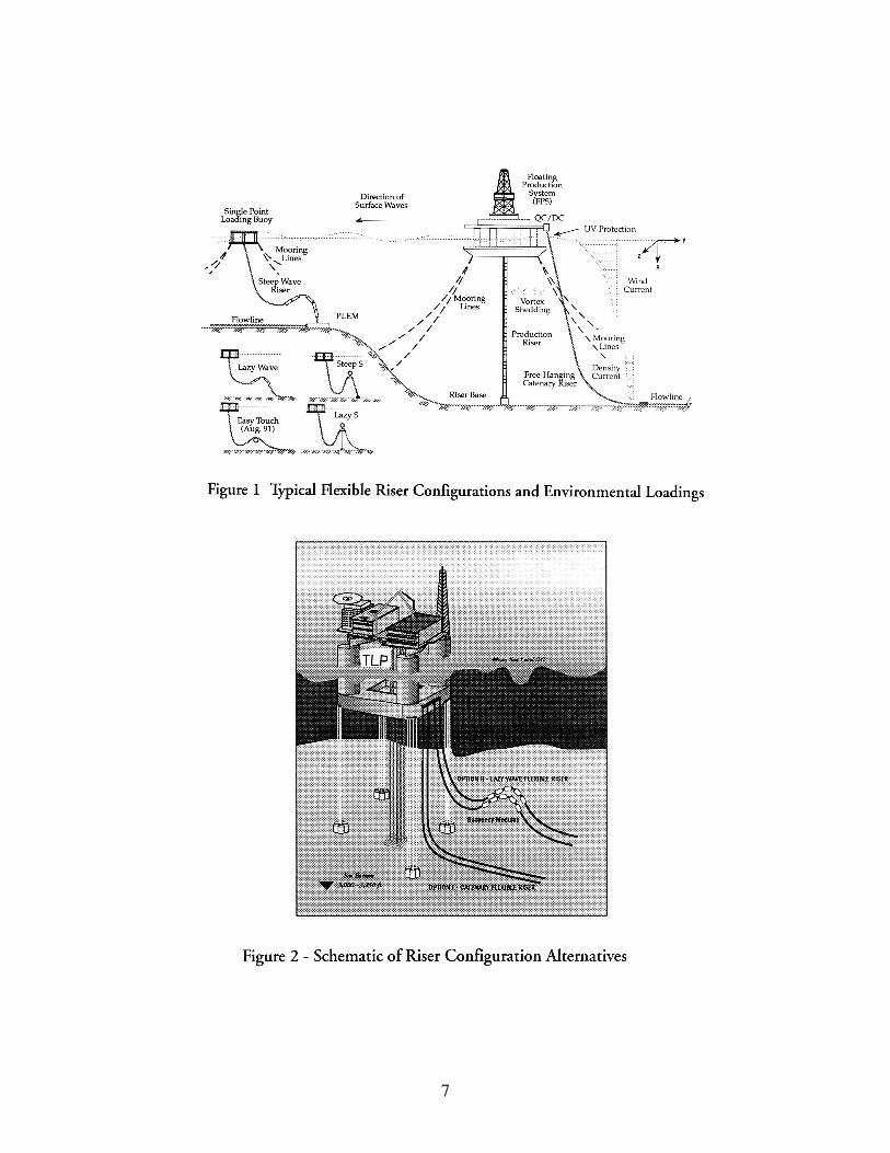
RISER DESIGN FOR TLP
Industry practice calls for several types of riser
configurations typically used in conjunction with
Floating Production/Loading Systems. The standard
five configurations generally used are:
Free-Hanging Catenary. Lazy-S. Lazy Wave, Steep-S,
and Steep Wave. Figure 1 illustrates these typical
types of riser configurations. The figure also illustrates
a schematic of a new riser configuration proposed by
Wellstream for the Alcorn Linapacan Field
Development Project. The choice of riser
configuration is usually based on economic criteria,
position of the wells, wave and current forces, motion
response and excursions of the vessel or surface buoy
as well. In the absence of TLP heave motion a Free-
Hanging Catenary riser configuration would be the
first choice.
To illustrate, design parameters impacting the
suitability of a particular configuration for use with
Tension Leg Platform, two riser design cases were
studied which reflect the selection of a Catenary
configuration versus a LazyWave configuration. (Fig.
2). The computer analyses were carried out at
Wellstream’s engineering offices using computer
program FLEXRISER-4 developed by Zentech, UK.
Design basis which was used in computer analyses is
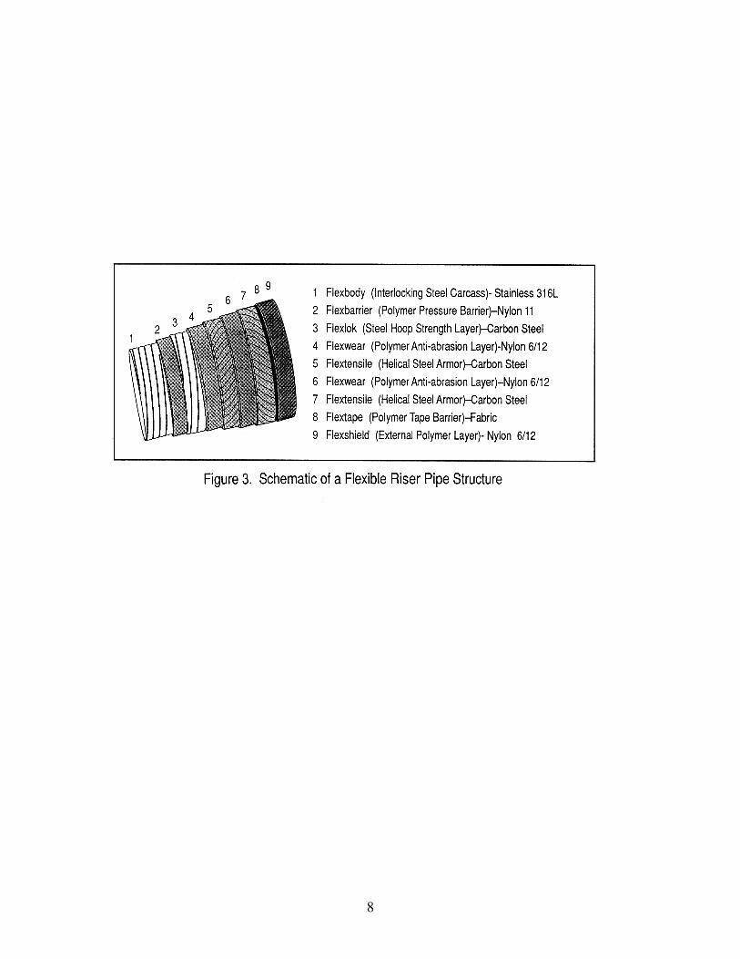
listed in Table 2. The design structure of the flexible
riser pipe is illustrated on Figure 3. The design of the
8-inch flexible pipe is based on multiphase flow
transport, 4000 psi design pressure and a 15-year
service life.
DESIGN CRITERIA
Efficient design of flexible riser systems is
made possible by using computer-based solution
techniques.
The design criteria of flexible riser systems is
usually based on allowable pipe curvatures and
tensions prescribed by the pipe manufacturer,
clearances between the riser and other structures, and
boundaries during its dynamic response. The
allowable curvatures and tensions are based on full-
scale test procedures and stress analysis carried out by
the manufacturer. These limits ensure the pipe is not
over-stressed when responding to dynamic loads and
vessel motions. The system is generally designed so
the pipe is tensioned throughout its dynamic response
cycle. Minimum clearances are also specified to avoid
clashing problems between riser and seabed, or riser
and vessel, and between the riser or other adjacent
risers, cables, or mooring systems.
DESIGN PARAMETERS AND PROCEDURES
The main problem in designing flexible riser
systems is the large number of design parameters. The
environmental conditions, vessel or calm buoy
motions and riser properties are usually well-defined.
The design procedure can be described as consisting
of three stages.
First Stage
The first stage in designing a flexible riser
system is determining an acceptable system layout.
The first stage is based on static analysis. It is normal
to carry out a parametric study assessing the effect of
changing the design parameters (i.e., system geometry
and length) on the static curvature and tension. Based
on the results of this parametric study, the design
selects a suitable range of system geometrics and
lengths satisfying the design criteria. The parametric
study will also assess the static effects of vessel offset
(displacement of the top end) and the current loading
in different directions.
Second Stage
The second stage in the design procedure is
performing a dynamic analysis of the system to assess
the global dynamic response. A system layout and
length is chosen from stage one and a series of
dynamic load cases are considered.
These load cases combine different wave and current
conditions, vessel or surface buoy positions, and riser
contents in order to prove an overall assessment of the
riser suitability in operational and survival conditions.
The corresponding analyses are then carried out and
dynamic curvatures, tensions and clearances are
checked against the design limits.
The majority of riser dynamic analyses
packages, including FLEXRISER-4, make use of the
3
“concept of effective tension” (Sparks. 1983). Sparks
addressed the drilling riser case where the riser is
essentially restrained. A catenary riser on the other
hand turns 900 to meet the sea bed. It is subject to
friction and can be subject to compression due to these
conditions. This concept accounts for the effects of
external and internal hydrostatic pressure acting on the
internal and external surfaces of the pipe wall. It is the
effective tension which controls the stability of the
riser from the point of view of deflection. The
relationship between effective tension, Teff, and the
“true wall” tension, Twail, that acts on the pipe wall
and contributes to stress in the pipe wall is:
Twall = Teff + (pi ± ρjg Hi) Ai – (ρ0g HO)AO………….(1)
where:
T wall = Wall tension to be used for stress calculation
in flexible pipe wall.
Teff = Effective tension as predicted by the riser
analysis computer program.
The effective tension is independent from
internal and external pressure. Given the effective
tension, as predicted by the riser global analysis
program, the true wall tension may be simply
calculated from the equation (1). Since internal
pressure affects the Twall, it is important to carefully
note the internal pressure conditions in the pipe under
the maximum load cases as well as the limiting
operational conditions when pressure in the riser may
be released or maintained.
Third Stage
The third stage in the design procedure is
performing detailed static and dynamic analyses of
local areas to design particular components. This stage
is presented in a separate publication (Brown, 1989).
Key papers by operators in this regard are Out
(1989), Boef (1990) of SIPM and de Oliveira (1985)
of Conoco. This third stage of design also includes a
question of life expectancy which has recently been
addressed by Claydon, et al (1991).
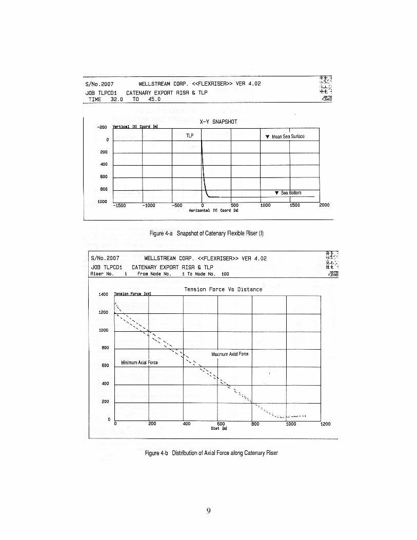
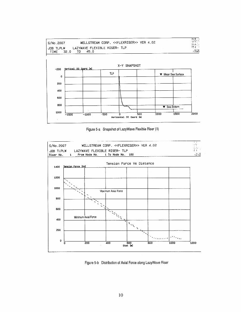
RESULTS OF RISER DESIGN
In order to illustrate the potential and the
limitations of adopting specific riser configurations,
results are presented of riser dynamics analyses for
two design cases of Catenary and LazyWave riser
configurations. Snapshots of the riser configuration
and distribution of axial force along the riser are
shown in Figures 4-a/b and 5-a/b, respectively for the
Catenary and LazyWave configurations. Although the
riser top tension for the LazyWave configuration is
only l00kN less than that for the Catenary, final
selection of configuration will depend on the total
allowable load exerted on the TLP and potential of
risers interference.
RISER SERVICE LIFE ANALYSIS
Limits on the service life of a flexible riser are
traditionally linked to weakening due to the wearing
away of tensile wire metal from repeated pipe flexure
as a result of environmental dynamic loading. Flexure
changes the natural position of the tensile wires,
giving the outer and inner tensile wires a tendency to
slide across each other so as to wear away a small
amount of metal during each flexure cycle. However,
friction due to contact pressures will prevent this
sliding unless the bend curvature is sufficiently great
and the bend radius is correspondingly small.
Moreover, when the wires are prevented from rubbing
directly on each other as a result of lubrication or
separation by an intervening plastic layer, there is a
dramatic reduction in the wear that will occur if the
wires do actually slide across each other. Finally, there
is life degradation only when wire stress levels are
high enough to bring fatigue failure mechanisms into
play. If initially the wire stresses were not sufficiently
high, they might become so later as a result of
reduction of wire cross section due to the wearing
away of metal. A preliminary life prediction analysis
was completed for the 8-inch riser. There appears to
be no chance of occurrence of the degradation process
described above, and therefore there is no resulting
limit to service life.
ANCILLARY EQUIPMENT FOR FLEXIBLE
RISERS
End Fittings.
Each flexible pipe has an end fitting to
connect one flexible pipe length to another or to the
customer’s facilities. The end fittings are designed to
terminate the ends of the layers, to maintain the
integrity of the pipe structure and to provide a flange
or other connection as required to mate with the
customer’s production facilities. Each of the flexible
pipe layers is individually terminated to maintain
fluid-tight integrity and to sustain the imposed loads.
The end fitting includes seals to ensure a reliable
fluid-tight seal to the Flexbarrier internal
thermoplastic layer and a seawater-tight seal to the
Flexshield outer thermoplastic layer.
Vent Valves.
Gas venting is provided in flexible pipes to
relieve pressure in the Flextensile annular space due to
the volume build-up of gas that permeates through the
Flexbarrier thermoplastic sheath. If pressure relief
were not provided, the outer sheath of the pipe could
rupture during service or retrieval. Permeation rates
are quite low and gap channels between Flextensile
wires are in general adequate to convey permeated gas
to vent valves in end fittings. In the event the vent
valves are insufficient to vent permeated gases, burst
disks in the outer sheath are provided to prevent
damage to large sections of the outer sheath.
4
Bend Stiffeners.
In order to prevent the flexible pipe from
traversing beyond its minimum bend radius during
severe storm conditions, bend stiffeners at the riser top
connection are specified if it is required. The bend
stiffeners consist of a polyether-polyurethane material
and are designed specifically to meet the requirements
of each project.
Cathodic Protection.
A cathodic protection system is specified to
minimize galvanic corrosion to exposed steel.
Sacrificial anodes are installed at each end fitting.
Distributed Buoyancy.
To provide for the distributed buoyancy
specified in the riser analysis for LazyWave
configuration, cylindrical buoyancy modules are
specified. The modules are molded of rigid syntactic
foam containing glass microspheres and fiberglass
macrospheres encapsulated in a plastic resin. The
modules are covered with an integrally molded
fiberglass skin to protect against impact, abrasion and
handling damage.
CONCLUSIONS
Although the market demand and apparent
need for flexible pipes have been associated with
floating platforms, vessels and buoys, the recent use of
flexible pipeline systems with Tension Leg Platform
has advanced the flexible’s horizon in the market
place. As oil and gas production moves into the deeper
offshore waters, development strategies may require
the use of flexible pipe systems. These deepwater
projects will require the development of materials and
techniques whereby flexible pipes with these materials
can be manufactured efficiently and economically.
The most evident need is the availability of marine
vessels and equipment that will be needed to install
flexible pipe flowline and riser systems in water
depths of 1000 meters and greater. The second area is
to ensure technology development of foam materials
to meet buoyancy and thermal insulation requirements
in deep waters.
REFERENCES
American Petroleum Institute, 1987, “RP17B -
Recommended Practice for Flexible Pipe,” Houston,
TX.
Ashcombe, G.T., and Kenison, R.C., BP
Engineering, 1990, “The Problems Associated with
NDT of High Pressure Flexible Pipes,” Society of
Underwater Technology Conference, Aberdeen.
Beynet, P.A., and Frase, J.R., 1982, “Flexible
Riser for a Floating Storage and Offloading System,”
Proceedings Offshore Technology Conference, Paper
OTC 6436, Houston, TX.
Brooks, D.A., Kenison, R.C., and BP International
Limited, 1989, “Research & Development in Riser
Systems,” Subsea, London.
Brown, P.A., Soltanahmadi, A. and Chandwani,
R., 1989, “Problems Encountered in Detailed Design
of Flexible Riser Systems,” Int. Seminar on Flexible
Risers, University College, London.
Claydon, P., Cook, G., Brown, P.A., Chandwani,
R., Zentech International Ltd, London, 1991, “A
Theoretical Approach to
Prediction of Service Life of Unbonded Flexible Pipes
under Dynamic Loading Conditions,” I. Marine
Structures, preprint.
Hoffman, D., Ismail, N., Nielsen, R., and
Chandwani, R., 1991, “Design of Flexible Marine
Riser in Deep and Shallow Water,” Proceedings
Offshore Technology Conference, Paper OTC 6724,
Houston, TX.
Ismail, N.M., 1984, “Wave-Current Models for
Design of Marine Structures,” Journal of the
Waterway. Port, Coastal and Ocean Division, ASCE,
Vol. 110, No. 4.
Kastelein, H.J., Out, J.M.M., and Birch, AD.,
1987, “Shell’s Research Efforts in the Field of High-
Pressure Flexible Pipe,” Deepwater Offshore
Technology Conference, Monaco.
Kodaissi, E., Lemerchand, E., and Narzul, P.,
1990, “State of the Art on Dynamic Programs for
Flexible Riser Systems,” ASME Ninth International
Conference on Offshore Mechanics and Arctic
Engineering, Houston, TX.
Lopes, A.P., de silva Neto, S.F., Estefgn, S.F., and
Da Silveria, M.P.R., 1990, “Dynamic Behavior of a
Flexible Line Design Installation,” Proceedings
Offshore Technology Conference, Paper OTC 6437,
Houston, TX.
Machado, Z.L., and Dumay, J.M., 1980,
“Dynamic Production Riser on Enchova Field
Offshore Brazil,” Offshore Brazil Conference, Latin
America Oil Show, Rio de Janeiro.
Mahoney, T.R., and Bouvard, M.J., 1986,
“Flexible Production Riser System for Floating
Product Application in the North Sea,” Proceedings
Offshore Technology Conference, Paper OTC 8163,
Houston, TX.
Oliveira, J.G., de Goto, Y., and Okamoto, I., 1985,
“Theoretical and Methodological Approaches to
Flexible Pipe Design and Application,” Proceedings
Offshore Technology Conference, Paper OTC 5021,
Houston, TX.
5
Oien, L., and Sandnes, 1.’ 1988, “Deepwater
North Sea Development: Snorre Field Concept,”
Proceedings Offshore Technology Conference, Paper
OTC 5830, Houston, TX.
Out, J.M.M., 1989, “On the Prediction of the
Endurance Strength of Flexible Pipe,” Proceedings
Offshore Technology Conference, Paper OTC 6165,
Houston, TX.
Sparks, C.P., 1983, “The Influence of Tension,
Pressure and Weight on Pipe and Riser Deformation
and Stresses,” 2nd International Offshore Mech and
Arctic Engineering Symposium, Houston, TX.
Tillinghast, W.S., Lecomete, H., Sturdevant, L.A.,
and Cranham, P., Nov. 1991, “Jolliet Project Proves
Flexible Pipe for Deepwater Development,” Oil &
Gas Journal, pp. 60-65.
Tillinghast, W.S., 1990, “The Deepwater Pipeline
System on the Jolliet Project,” Proceedings Offshore
Technology Conference, Paper OTC 6403, Houston,
TX.
Tillinghast, W.S. and Shah, B.C., 1987, “Laying
Flexible Pipelines Over Coral Reefs in the Geisum
Field, Gulf of Suez, Egypt,” Proceedings Offshore
Technology Conference, Paper OTC 5585, Houston,
TX.
6
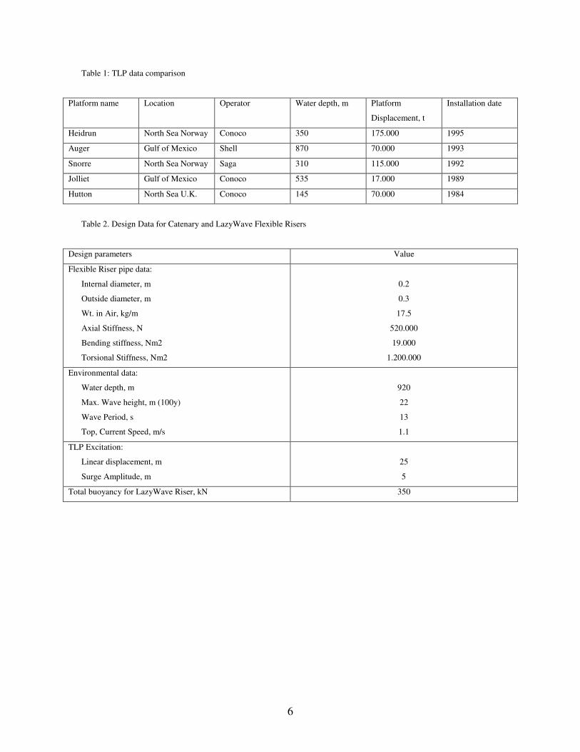
Table 1: TLP data comparison
Platform name Location Operator Water depth, m Platform
Displacement, t
Installation date
Heidrun North Sea Norway Conoco 350 175.000 1995
Auger Gulf of Mexico Shell 870 70.000 1993
Snorre North Sea Norway Saga 310 115.000 1992
Jolliet Gulf of Mexico Conoco 535 17.000 1989
Hutton North Sea U.K. Conoco 145 70.000 1984
Table 2. Design Data for Catenary and LazyWave Flexible Risers
Design parameters Value
Flexible Riser pipe data:
Internal diameter, m
Outside diameter, m
Wt. in Air, kg/m
Axial Stiffness, N
Bending stiffness, Nm2
Torsional Stiffness, Nm2
0.2
0.3
17.5
520.000
19.000
1.200.000
Environmental data:
Water depth, m
Max. Wave height, m (100y)
Wave Period, s
Top, Current Speed, m/s
920
22
13
1.1
TLP Excitation:
Linear displacement, m
Surge Amplitude, m
25
5
Total buoyancy for LazyWave Riser, kN 350
7
8
9
10