flexible couplings - translev · unique coupling design ... 2 the torque capacity of flexible...
TRANSCRIPT

flexible couplings
www.translev.se [email protected]: 08-446 39 90 fax: 08-756 44 73
tlf: 08-
.twww -446 39 90
.seanslevtr fax: 08
info@ 8-756 44 73
.seanslev@tr 3

Product Overview
+44 (0) 1992 501900
4
Long
9-convolution
Stretched
2-convolution
High-end servo drives, pulse
generators, scanners,
positioning slides, metering
valves, etc.
Stainless Steel
Bellows type
Precision couplings withexcellent kinematicproperties. The 3 types offerdiffering combinations ofstiffness, radialcompensation and axialmotion.
Up to 5000 rpm in standard
form.
12.5 Nm
3 to 20
–40° to +120°C
No, unless used with
insulating bore adaptors
Clamp or Set Screw
Standard bores
Temperature range
Connection
Electrically isolating
Peak torque largest size
Speeds
Where to use
General description
Page 12 - 13 Page 14 - 15 Page 16 - 19 Page 28 - 33 Page 34 - 35 Page 36
Flex B
Short 3-convolution
High-end servo drives, pulse
generators, scanners,
positioning slides, metering
valves, etc.
Nickel
Bellows typeMembrane type Multi-Beam type Single-Beam type Step-Beam type
Precision couplings withexcellent kinematicproperties. The 3 types offerdiffering combinations ofstiffness, radialcompensation and axialmotion.
Up to 5000 rpm in standard
form.
12.5 Nm
3 to 20
–40° to +120°C
No, unless used with
insulating bore adaptors
Clamp or Set Screw
Flex Ni Flex M
Single-stage
Short two-stage
Long two-stage
Material Options:
Aluminium
Stainless Steel
Acetal
Multi-Beam
6-Beam
High-end servo drives, pulse
generators, scanners,
positioning slides, high
speed dynamometers,
unsupported drive shafts,
etc.
Stepper and servo drives,
encoders, general purpose
light duty power
transmission applications.
Precision couplings withexcellent kinematicproperties. Dynamicallybalanced construction.Single-stage versions makeup into ‘whirl’ free Cardans.The 2-stage versions offershort envelopes and lowbearing loads respectively.
General purpose single piececouplingsSingle stage (3-beam)Two stage (6-beam)Material options formoisture and corrosionresistance.
No, unless used with
insulating bore adaptors
Clamp or Set Screw Clamp or set screw
Aluminium }No
Stainless Steel }
Acetal Yes
Up to 5000 rpm in standard
form.
Up to 30000 rpm in
balanced form.
60 Nm
3 to 28
–40° to +120°C
Up to 5000 rpm in standard
form.
Up to 30000 rpm in
balanced form.
140 Nm
1 to 38
–40° to +140°C
Material Options:
Aluminium
Stainless Steel
Single-Beam
Stepper drives, encoders,
general purpose light duty
power transmission
applications.
More flexible than Multi-Beam but lesstorsional rigidity.
Clamp or Set Screw
Aluminium }No
Stainless Steel }
Up to 5000 rpm in standard
form.
Up to 30000 rpm in
balanced form.
30 Nm
3 to 26
–40° to +140°C
Material Options:
Nylon
Step-Beam
Encoders, tachogenerators,
small pumps, motors and
drives
Unique coupling designgives excellent combinationof radial flexibility withtorsional stiffness.
Clamp or Set Screw
Yes
Up to 10000 rpm
25 Nm
3 to 12.7
–20 to +150°C
Pro
duct
Ove
rvie
w
2
C
www.translev.se [email protected]: 08-446 39 90 fax: 08-756 44 73
tlf: 08-
.twww -446 39 90
.seanslevtr fax: 08
info@ 8-756 44 73
.seanslev@tr 3

Product Overview
5
www.huco.com
General description
Standard bores
Temperature range
Connection
Electrically isolating
Peak torque largest size
Speeds
Where to use
Vari-Tork
Basic clutch
Basic clutch +
sleeve adaptor
Basic clutch +
Oldham coupling
L-Box
T-Box
Small, user-adjustabletorque limiters forconcentric or in-linemounting. Operate by friction usinginterleaved clutch plates.
Friction clutches interrupt
rotation when the load
being transmitted reaches a
pre-determined threshold.
Used in all kinds of small
drives to help protect
personnel
and equipment.
Small 90° drives encasedin molded housingsproviding electricalisolation between shaftsand mounting surface.The L-Box is rated forintermittent use, the T box for continuous.1:1 & 2:1 ratios areavailable with the T-Box.
L-box offers a compact
means to route drives
thru’ 90°.
T-box offers 2 & 3 shaftconfigurations for
multiple power offtake.
Clamp or Set Screw N/A
Up to 1000 rpm
slipping speed
3 Nm
6 to 20
–10 to +80°C
(when operating)
No
Up to 1500 rpm for
T-box
0.68 Nm
4 & 5 (shafts)
–20 to +60°C
See General Description above
Page 24 - 26 Page 22 - 23 Page 40 Page 38 - 39 Page 44 - 48 Page 50 - 52 Page 54
Sliding Disc typeUniversal / Lateral
typeDouble Loop type Jaw Coupling
Universal Joints
& TeleshaftsFriction Clutches Bevel Gearboxes
Oldham
Blind bored
Thru’ bored
Thru’ bored
Huco-Pol
Single joints
Double joints
Teleshafts
Encoder, resolver, tacho,
potentiometer drives. Small
positioning slides, dosing
pumps, & light drivesgenerally.
Light power drives, pumps
and small generators
Light power drives where
misalignment is small
Intermittent applications in
business machines,
instrumentation, lab
equipment, analytical
apparatus, etc., where steel
joints would be under-
utilised.
Stepper drives for most
applications including
positioning slides, pumps,
actuators, etc.
Uni-Lat Flex-P Jaw coupling
General purpose, robust,easy to use 3-part couplingswith replaceable wearelements.Generous radialcompensation and pull-apart / re-engage facility forblind assemblies.
Unique, general purposelight duty couplings withgenerous angular and radialmisalignment compensation.Resist axial motion, cananchor unrestricted shaftsand perform light push/pullduties.
Light duty plastic universaljoints and extensible driveshafts (teleshafts). Low mass, corrosionresistant, ideal whereconventional steel jointswould be under-utilised.
Exceptional flexibility in allthree directions, radial,angular and axial
High torque capacity andhigh speed are availablefrom this naturally balancedcoupling
Clamp or Set Screw Clamp or Set Screw Set Screw Clamp or Set Screw Set Screw, Bonding, or
Cross-Pinning
Up to 3000 rpm.
44 Nm
2 to 30
–20 to +60°C
Yes
Up to 3000 rpm. Up to 3000 rpm. Up to 40,000 rpm.
12 Nm 18 Nm 133 Nm
3 to 22 3 to 16 3 to 16
–20 to +60°C –40 to +100°C –40 to +80°C
Yes Yes Yes
Up to 1000 rpm
10.7 Nm
3 to 20
–20 to +60°C
Yes
Material Options:
Aluminium
Stainless Steel
C
3
www.translev.se [email protected]: 08-446 39 90 fax: 08-756 44 73
tlf: 08-
.twww -446 39 90
.seanslevtr fax: 08
info@ 8-756 44 73
.seanslev@tr 3

Selecting Flexible Couplings
+44 (0) 1992 501900
6
Note 1: Not recommended in these conditions
Service Factors
2 Peak torque values quoted in the coupling performance tables apply to uniform load conditions at constant speed where there is no misalignment
or axial displacement.
2 The torque capacity of flexible couplings will reduce when acceleration is present, for example, in stop/start or reversing conditions.
2 The more severe the acceleration, the greater reduction in torque capacity.
2 Sliding couplings (Oldham and UniLat) are subject to a wear rate dependent on the number of cycles completed.
Load
Steady
State
1.5 2.0 2.0 3.0 4.0 - - - - -
1.5 2.0 2.0 3.0 4.0 - - - - -
1.0 2.0 2.0 3.0 4.0 - - - - -
1.0 1.5 1.5 3.0 4.0 - - - - -
1.0 2.0 4.0 4.0 4.0 - - - - -
1.0 1.5 2.0 (Note 1) (Note 1) - - - - -
1.0 1.5 2.0 (Note 1) (Note 1) - - - - -
1.0 1.5 2.0 (Note 1) (Note 1) - - - - -
- - - - - 1.0 2.0 4.0 6.0 8.0
- - - - - 1.0 1.5 2.0 3.0 4.0
Huco Flex B
Huco Flex M
Huco Flex Ni
Huco Flex P
Huco Flex G
Huco MultiBeam
Huco S-Beam
Huco TorqLink
Huco Oldham
Huco Flex - B
- - - - - 1.0 1.5 2.0 3.0 4.0Uni-Lat
Stop/Start Reversing ShockShock &
Reversing<1 1 - 2 3 - 5 6 - 12 >12
Duty (Hours/Day)
In the simplest of terms a coupling’s
purpose is to transfer rotational
movement from one shaft to another.
Reality is somewhat more complicated,
though, as flexible shaft couplings have
also to compensate for misalignment
between two shafts. This ability must be
balanced with the need to be pliable in
the planes of misalignment while still
having the torsional strength to carry out
the coupling’s main function. This is
known as the Compliance mechanism
where compliance is the capacity for
allowing relative displacement.
Several factors should always be taken
into consideration when looking to specify
flexible shaft couplings. These are
torsional stiffness, backlash, torque, life
and attachment system. All of these have
bearing on coupling selection.
The choice of couplings available to today’s engineers can be daunting,
but follow our guide;lines and you will arrive at the optimum coupling
for your particular application.
2 Does the coupling provide adequate misalignment protection?
2 Can it transmit the required torque?
2 Do I need axial motion or axial stiffness?
2 Can it sustain the required speed of rotation?
2 Will it fit within the available space envelope?
2 Can it operate at the designated ambient temperature?
2 Does it provide torsional stiffness required for positionalaccuracy?
2 Does it provide electrical isolation between the shafts?
2 Will it have the required life expectancy?
Introduction tocouplings
Selecting the idealcoupling
Peak torque must be greater than application torque x service factor
4
C
www.translev.se [email protected]: 08-446 39 90 fax: 08-756 44 73
tlf: 08-
.twww -446 39 90
.seanslevtr fax: 08
info@ 8-756 44 73
.seanslev@tr 3

Round & Keywayed Bore Details & CodesMetric
mm
Inch
fraction
Inch
decimal
Round
bore
code
Keywayed
bore
codeKey size
w x h
Key size
w x hK K
Metric keys Inch keys
1 – 0.0394 08 – – – – –1.588 1/16 0.0625 10 – – – – –2 – 0.0787 11 – – – – –
2.286 – 0.0900 12 – – – – –2.382 3/32 0.0938 13 – – – – –3 – 0.1181 14 – – – – –
3.048 – 0.1200 15 – – – – –3.175 1/8 0.1250 16 – – – – –*3.969 5/32 0.1563 – – – – – –
4 – 0.1575 18 – – – – –4.763 3/16 0.1875 19 – – – – –5 – 0.1969 20 – – – – –
5.556 7/32 0.2188 21 – – – – –6 – 0.2362 22 – – – – –6.096 – 0.2400 23 – – – – –
6.350 1/4 0.2500 24 – – – – –7 – 0.2756 25 2 x 2 8.00 – – P257.144 9/32 0.2813 26 – – – – –
7.938 5/16 0.3125 27 – – 1/8 x 1/8 0.3755 R278 – 0.3150 28 2 x 2 9.00 – – P288.731 11/32 0.3438 29 – – 1/8 x 1/8 0.4068 R29
9 – 0.3543 30 3 x 3 10.40 – – P309.525 3/8 0.3750 31 – – 1/8 x 1/8 0.4380 R31
10 – 0.3937 32 3 x 3 11.40 – – P32
11 – 0.4331 33 4 x 4 12.80 – – P3311.113 7/16 0.4375 34 – – 1/8 x 1/8 0.5005 R3412 – 0.4724 35 4 x 4 13.80 – – P35
12.700 1/2 0.5000 36 – – 1/8 x 1/8 0.5630 R3613 – 0.5118 37 5 x 5 15.30 – – P3714 – 0.5512 38 5 x 5 16.30 – – P38
14.288 9/16 0.5625 39 – – 3/16 x 3/16 0.6535 R3915 – 0.5906 40 5 x 5 17.30 – – P4015.875 5/8 0.6250 41 – – 3/16 x 3/16 0.7160 R41
16 – 0.6299 42 5 x 5 18.30 – – P4217 – 0.6693 43 5 x 5 19.30 – – P4317.463 11/16 0.6875 44 – – 3/16 x 3/16 0.7785 R44
18 – 0.7087 45 6 x 6 20.80 – – P4519 – 0.7480 46 6 x 6 21.80 – – P4619.050 3/4 0.7500 47 – – 3/16 x 3/16 0.8410 R47
20 – 0.7874 48 6 x 6 22.80 – – P4822 – 0.8661 49 6 x 6 24.80 – – P4922.225 7/8 0.8750 50 – – 1/4 x 1/4 0.9930 R50
24 – 0.9449 51 8 x 7 27.30 – – P5125 – 0.9843 52 8 x 7 28.30 – – P5225.400 1 1.0000 53 – – 1/4 x 1/4 1.1180 R53
28 – 1.1024 54 8 x 7 31.30 – – P5428.575 1-1/8 1.1250 55 – – 5/16 x 1/4 1.2400 R5530 – 1.1811 56 8 x 7 33.30 – – P56
31.750 1-1/4 1.2500 57 – – 5/16 x 1/4 1.3580 R5732 – 1.2598 58 10 x 8 35.30 – – P5834.925 1-3/8 1.3750 59 – – 3/8 x 1/4 1.4830 R59
35 – 1.3780 60 10 x 8 38.30 – – P6038 – 1.4961 61 10 x 8 41.30 – – P61
*Not manufactured. Nearest alternative 4mm.
How to Order
7
www.huco.com
All shaft mounted products in this catalogue can
be specified with inch and/or metric bore
diameters. A standard range of sizes is listed for
each product. Where physical dimensions permit,
keyways may be specified at extra cost.
For the sake of uniformity and avoidance of errors
when ordering, bore diameters are designated with
a 2-digit number which forms part of the order
code.
Please note that only the bore diameters listed for each
product in the product pages are standard.
The table below lists the 2-digit designations for
bore diameters spanning 1mm to 38mm and
includes the metric equivalents for bores
conforming to inch sizes. The columns at the right
of the table show the key dimensions for the
related bores. Designations for keywayed bores are
shown in the last column.
To specify a keywayed bore, prefix the 2-digit
number with a ‘P’ for metric keyways or an ‘R’ for
an inch keyway.
Standard keyways are machined to 2 specifications:
Bore codes prefixed 'P' denote a metric keyway
conforming to
ISO 773/774 (BS 4235 Pt. 1).
Bore codes prefixed 'R' denote an inch keyway
conforming
to BS 46 Pt. 1.
In most cases, keyways prefixed 'R' are compatible
with AGMA 9002–A86 but can differ in the depth of
the key seat. Shafts fitted with AGMA keys should
be measured to determine dimension K and the key
width. If these do not conform to the values shown
in the table, please photocopy this page and enter
the required dimensions on the drawing below.
Please enter all three dimensions, key width, shaft
diameter and dimension K.
Combine the COUPLING REF in Main
Product Tables with BORE REFS in
Standard Bores Table.
Please identify both bores e.g.
Order Codes
706.19.1924Coupling ref.
Ø B1 ref.
Ø B2 ref.
C
5
www.translev.se [email protected]: 08-446 39 90 fax: 08-756 44 73
tlf: 08-
.twww -446 39 90
.seanslevtr fax: 08
info@ 8-756 44 73
.seanslev@tr 3

Installing Couplings
+44 (0) 1992 501900
8
Flexible Coupling Types
General instructions1. Ensure that shafts are free of burrs, damage, or foreign matter, and can penetrate the bores.
2. Install the coupling by holding the shaft and the related hub, rotating it back and forth as you progress it along the shaft.
3. Do not apply any forces that cause extension, compression or lateral displacement of the coupling beyond its permissible offsets.
Example 1. With partially supported (1 bearing) shafts.
Example 2. With unsupported intermediate shafts.
Single-stage couplings are radially supportive and function as
supplementary bearings. They are used when the connected shaft lacks a full
complement of bearings.
Note: Bellows couplings do not provide the same level of radial support as Flex M when used with partially or wholly unsupported shafts. When essential for
reasons of greater axial motion, use the 3-convolution type for these purposes.
Two-stage couplings are radially compliant and are used when both shafts
are fully supported by bearings.
a) Position and secure the larger of the 2 shafts (if different) and progress
the coupling onto it.
b) Progress the second shaft into the bore, taking care not to lever either
shaft against the inner wall of the spacer.
c) Progress the coupling along the shafts to a position midway between the
shaft terminations. Rotate the coupling to ensure it is not binding and is in
its natural state, ie., neither extended nor compressed.
d) Align the second shaft with the first using a straight edge and feeler
gauges or a dial indicator.
e) Secure the second shaft and re-check alignment. Final alignment must be
within the permissible offsets.
f) Secure one hub, tightening each screw alternately. Repeat for the second
hub.
Normal installation When to use single & two-stage couplings
Single-stage
Two-stage
r
CAUTIONThese are precision high couplings that have a limited range of
permissible flexure. They can be damaged through careless handling.
Avoid gratuitous flexure in any direction.
No axial forces are permitted across the membranes when fitting
Huco-Flex M couplings. Keyways with interference fits are not
recommended.
Bellows couplings are more tolerant of axial motion, but flexure beyond
the permissible limits should be avoided.
6
C
www.translev.se [email protected]: 08-446 39 90 fax: 08-756 44 73
tlf: 08-
.twww -446 39 90
.seanslevtr fax: 08
info@ 8-756 44 73
.seanslev@tr 3

Installing Couplings
9
www.huco.com
Sliding Disc type (Oldham)
L2
L/H Shaft
L/H Shaft
L/H Shaft
R/H Shaft
R/H Shaft
R/H Shaft
R/H ShaftL/H Shaft
R/H Shaft
gap gauge
L/H Shaft
L/H Shaft
R/H Shaft
Gap gauges for all hub types
Coupling size 06, 09 & 13 Gap gauge 0.05mm
19 & 25 0.10mm
33 & 41 0.15mm
50 & 57 0.20mm
Clearances are set to allow for thermal shaft growth and / or end-float. Gaps
may be increased, but total shaft movement should not exceed the values
shown under Axial Compensation in the Performance Table.
Radial support
Shafts must be fully supported by 2 bearings and have minimal overhang.
Oldham couplings cannot be used in pairs.
Clamp hubs
To improve clamp action, apply a little grease under the
head of the clamp screw.
Note: It is important that installed couplings are not end-loaded. To help avoid this, thro’ bored hubs are recommended for shafts which have fixed axial
locations such as face-mounted motors.
right
wrong
Blind hub
a) Slide hubs on to both shafts until fully seated and tighten screws.
b) Position and secure R/H shaft.
c) Seat disc fully on R/H hub.
gap gauge
d) Place a gap gauge flat against the bottom of the exposed slot in the
disc and push the L/H hub into full engagement by manipulating the
L/H shaft.
e) Align shafts within the permissible offsets and secure L/H shaft.
f) Check alignment and correct if necessary.
g) Remove gap gauge.
To fit a new disc, withdraw L/H shaft complete with hub and remove old
disc. Repeat steps c) to g).
Thro' hub
a) Slide hubs on to both shafts.
b) Align shafts to within the permissible offsets and position to leave
minimum gap 2 between terminations. Secure both shafts, check
alignment and correct if necessary.
c) Position R/H hub with inboard face flush with shaft termination and
tighten screws.
d) Slide disc radially on to the tenons of the R/H hub. Ensure the disc is fully
seated.
e) Place a gap gauge flat against the bottom of the exposed slot in the disc
and push the L/H hub into full engagement.
f) Tighten fastening screws and remove gap gauge.
To fit a new disc, slacken the fastening screws on one hub and retract it
along the shaft. Slide the old disc out radially and replace with the new.
Repeat steps d) to f).
To retain shaft phasing, withdraw L/H shaft and repeat steps c) to g) as for
Blind hub couplings.
Over-penetration of shafts can impair function of coupling with solid disc.
Min shaft gap L2 must be observed. Specify thro' bored disc for near-butted
shafts.
Coupling size 19 25 33 41 50 57
L2 min 7.2 9.2 12.0* 15.3 18.4 21.2
*types 243, 245, 454 and 456 = 18.0
C
7
www.translev.se [email protected]: 08-446 39 90 fax: 08-756 44 73
tlf: 08-
.twww -446 39 90
.seanslevtr fax: 08
info@ 8-756 44 73
.seanslev@tr 3

Installing Couplings
+44 (0) 1992 501900
10
Relief Under The BeamsMost Multi-Beam couplings can be supplied with or without relief
under the beams as shown in the diagrams below. When the drive or
driven shafts extend under the beams relief is essential to ensure that
the coupling remains flexible. Where non-relieved versions are used,
shafts must not be allowed to penetrate under the beamed section of
the coupling. Unless otherwise specified, relieved versions will be
supplied.
Pilot BoresCouplings can be supplied ‘pilot bored’ for opening out by the
customer. Pilot bores are plain drilled holes, which are not produced
with the same accuracy as finished machined bores. The largest bore
provided in a pilot bored product is that needed to make the coupling
flexible and this will always be larger than the minimum possible bore
size ‘B1’ shown in the bore tables. For sizes 13 to 25, the pilot bore is
also larger than the ‘B2’ minimum shown in the bore tables. Further
details are available on request.
Relieved
Non-Relieved
��
Beam Type
8
C
www.translev.se [email protected]: 08-446 39 90 fax: 08-756 44 73
tlf: 08-
.twww -446 39 90
.seanslevtr fax: 08
info@ 8-756 44 73
.seanslev@tr 3

high performancecouplings• Stainless Steel Bellows
• Nickel Bellows
• Flexible Membrane (Disc)
• Torsionally rigid design
• No moving parts
• All-metal construction
• Low inertia
The operating principles of Flex B, Flex Ni and
Flex M offer the highest performance available with flexible
couplings.
With excellent kinematic properties and torsional stiffness of a very
high order, they are suitable for servo drives and satisfy the criteria
for highly dynamic position and velocity control systems.
Bellows couplings have the greater torsional stiffness while Flex M
have the more tolerant flexural system and feature dynamically
balanced construction.
www.translev.se [email protected]: 08-446 39 90 fax: 08-756 44 73
tlf: 08-
.twww -446 39 90
.seanslevtr fax: 08
info@ 8-756 44 73
.seanslev@tr 3

Flex - B Stainless Steel Bellows Couplings
+44 (0) 1992 501900
12
Ref. 530
Short type
for precisely aligned shafts
Ref. 532
Long type
for greater angular offsets
or axial motion
Ref. 534
Stretched type
for greater radial misalignment
and lower bearing loads
Typical
TypicalRef. 536 & 537Short type
for precisely aligned shafts
Ref. 538 & 539Long type
for greater angular offsets
or axial motion
Ref. 540 & 541Stretched type
for greater radial misalignment
and lower bearing loads
Set screw hubs
Clamp hubs
Comparative properties
L1
L1
L1
L1
L1
L1
L1
L1
L1
L1
L1
L1
L
L
L
L
L
L
ØB1
ØB1
ØB1
ØB1
ØB1
ØB1
ØB2
ØB2
ØB2
ØB2
ØB2
ØB2
ØD
ØD
Materials & Finishes
Hubs: Al. Alloy 2014T6 and AIEco 62sn T9 Clear anodised finish
Bellows: Spring quality stainless steel
Joint assembly: Copper C106, heat treated Zinc plate, clear passivate
Fasteners: Alloy steel, black oiled
The properties of the 3 types
compared on a scale of 1 to 3.
3 = best.
Peak Torque
Parameter
Type
2
3
2
2
1
1
1
3
3
3
3
2
1
1
2
Short Long Stretched
Torsional Stiffness
Angular Compensation
Axial Compensation
Radial Compensation
Temperature Range
–40°C to +120°C
10
C
www.translev.se [email protected]: 08-446 39 90 fax: 08-756 44 73
tlf: 08-
.twww -446 39 90
.seanslevtr fax: 08
info@ 8-756 44 73
.seanslev@tr 3

13
www.huco.com
Flex - B Stainless Steel Bellows Couplings
Coupling
SizeSet
Screw
Hubs
Clamp
Hubs
ØD L L1 ØB1, ØB2
max
Fasteners Moment
of inertia
kgm2
x 10–8
Screw Torque Wrench kg
x 10–3±1.0 mmNm
Mass
20
26
34
41
20.0
26.0
34.0
41.0
31.0
11.0 8
12
16
20
M4 2.27 2
4–40 2.33 2
M5 4.62 2.5
M3 2.43 2.5
M5 4.62 2.5
M3 2.43 2.5
M6 7.61 3
M4 5.66 3
90
100
90
90
100
90
350
400
370
330
350
975
1128
988
925
1078
938
2490
2740
2477
2390
2660
2377
380
18
19
18
16
18
17
35
39
34
34
38
33
58
65
59
56
63
57
102
110
102
99
107
99
14.0
14.0
18.0
45.2
43.6
31.0
45.2
43.6
37.5
54.3
53.2
37.5
54.3
53.2
40.0
57.0
56.6
40.0
57.0
56.6
49.7
71.4
70.7
49.7
71.4
70.7
1 3 3
2
530.20
532.20
534.20
–
–
–
530.26
532.26
534.26
–
–
–
530.34
532.34
534.34
–
–
–
530.41
532.41
534.41
–
–
–
–
–
–
537.20
539.20
541.20
–
–
–
536.26
538.26
540.26
–
–
–
536.34
538.34
540.34
–
–
–
536.41
538.41
540.41
COUPLING REF
1. Length of supported thro’ bore. Shafts can near-butt.
2. Maximum recommended tightening torque.
3. Values apply with max bores.
4. Peak torque. Select a size where PeakTorque exceeds the application torque xservice factor. (see page 6)
5. Max. compensation values are mutuallyexclusive.
6. Torsional stiffness values apply at 50% peaktorque with no misalignment, measured shaft-to-shaft with largest standard bores.Note that in some vendors’ catalogues thegiven torsional stiffness applied to theun-mounted bellows element only, anunrepresentative calculated value.
STANDARD BORES
Coupling
Size
Ref. Peak
torque
Nm
20
26
34
41
530 & 537
530 & 536
530 & 536
530 & 536
532 & 539
532 & 538
532 & 538
532 & 538
534 & 541
534 & 540
534 & 540
534 & 540
2.0
1.0
2.5
3.2
1.6
4.0
7.5
3.8
9.4
10.0
5.0
12.5
2
6
1.3
2
6
1.3
2.5
8
1.5
2.5
8
1.8
0.06
0.50
0.20
0.06
0.50
0.20
0.10
1.00
0.30
0.15
1.20
0.40
0.35
1.00
0.20
0.36
1.00
0.20
0.60
1.90
0.30
0.80
2.50
0.50
315
170
225
755
380
615
1740
915
1455
2880
1310
2245
1.03
0.33
0.33
1.27
0.39
1.52
1.34
0.62
1.98
1.58
0.52
2.30
115
6.7
8.2
238
8.2
14.6
227
12.7
23.2
144
9.3
19.2
17.7
7.8
7.1
5.7
3.3
6.4
6.6
3.8
27.9
13.1
3.8
7.2
Max compensation Flexural stiffness
Angular
deg
Radial
mm
Axial
± mm
Torsional
Nm / rad
Angular
N / deg
Radial
N / mm
Axial
N / mm
4 5 6
ØB1, ØB2 +0.03/–0mm
3 3.175 4 4.763 5 6 6.350 8 9 9.525 10 11 12 12.700 14 15 15.875 16 18 19 19.050 20
Coupling
Size
20 � � � � � � � �
� � � � � � � � � � �
� � � � � � � � � � � � �
� � � � � � � � � � � � � � � �14 16 18 19 20
251
22 24
253
28
255
30 31 32
257
33 35 36
259
38 40 41 42 45 46 47 48
260 261
26
34
41
Bore ref.
Corresponding
bore adaptor
PERFORMANCE
Diameters for which a bore adaptor is shown can be adapted to smaller shaft sizes. See page 56 for details of metallic and electrically insulating adaptors.
DIMENSIONS & ORDER CODES
Load capacity depends on
application conditions:
see page 6 for details
IMPORTANT
C
11
www.translev.se [email protected]: 08-446 39 90 fax: 08-756 44 73
tlf: 08-
.twww -446 39 90
.seanslevtr fax: 08
info@ 8-756 44 73
.seanslev@tr 3

Flex-Ni Nickel Bellow Couplings
+44 (0) 1992 501900
14The convolutions of Flex-Ni Couplings are formed by the electrolytic deposition of nickel. This produces
stress-free convolutions with closely controlled wall thickness.
Nickel bellows couplings are characterised by their exceptional quality of rotational positional integrity.
This is achieved through high torsional stiffness in a coupling that is still able to accommodate large
amounts of lateral and angular misalignment due to low spring rates in these directions. These couplings
are used primarily in instrumentation and similar sensitive applications.
Set Screw Hubs
Clamp Hubs
Materials & Finishes
Hubs: Aluminium Alloy
Bellows: Electrodeposited nickel
Fasteners: Alloy steel
Temperature Range
–50°C to +120°C
Ref. 321 Ref. 321
Ref. 323Ref. 323
12
C
www.translev.se [email protected]: 08-446 39 90 fax: 08-756 44 73
tlf: 08-
.twww -446 39 90
.seanslevtr fax: 08
info@ 8-756 44 73
.seanslev@tr 3

15
www.huco.com
Flex-Ni Nickel Bellow Couplings
DIMENSIONS & ORDER CODES
SizeNumber of
convolutions Set Screw
HubClamp Hub O.D
O/A
Length
L
Max Shaft
Depth
L1
Max Bores
Moment of
Inertia
kgm2
x 10-8
Mass kg
x 10-3Size
Torque
(Ncm)
A/F
(mm)
Order Code Dimensions Fasteners
7 8 321.07 - 6.35 14 4 3.175 1.3 1.5 M2 41 0.9
12 14 321.12 - 12 23 6 6.35 18.5 10 M2.5 79 1.3
17 14321.17 - 17 27 7 10 36.2 8.5 M3 132 1.5
- 323.17 16.3 29 8 6.35 46.6 11.0 M2 35 1.5
25 10321.25 - 25 33 7 12.7 161.0 19.5 M3 132 1.5
- 323.25 25 37 9 12.7 245.0 28.5 M2.5 66 2.0
36 7321.36 - 36.3 42.3 9.5 19.05 601.0 39.0 M6 510 3.0
- 323.36 36.3 46.9 11.8 19.05 2960.0 85.0 M4 262 3.0
50
Size
Peak
Torque
(Ncm)
Wind up
Arcs/Ncm Angular Deg Radial mm Axial mmTorsional
(Nm/rad)
Angular
(N/deg)
Radial
(N/mm)
Axial
(N/mm)
Max misalignment compensation Nominal Spring Rates
11321.50 - 51 59.3 10.5 20 952.0 52.0 M6 860 3.0
- 323.50 51 61.9 11.8 20 3560.0 105.0 M4 262 3.0
PERFORMANCE
AVAILABLE BORES
7 4.9 285 10 0.19 0.65 7 <0.15 6.9 3.5
12 13 75 15 0.54 1.72 27 <0.15 4.2 2.2
17 50 20 10 0.43 1.78 103 0.15 12.3 4.0
25 328 4.0 8 0.46 2.07 515 0.41 38.1 11.2
36 918 1.2 6 0.46 3.28 1719 0.32 87.8 20.2
50
SizeØ B1, B2 H8
3 3.175 4 4.763 5 6 6.350 8 9.525 10 12 12.700 16 19.050 20
1624 0.6 9 1.12 6.1 3438 <0.15 57.8 17.6
• • •7
• • • • • • •12
• • • • • • • S S S17
• • • • • • •25
• • • •36
• • • • •50
14 16 18 19 20 22 24 28 31 32 35 36 42 47 48Bore Ref.
S = Setscrew only
Load capacity depends onapplication conditions: see page 6 for details
IMPORTANT
C
13
www.translev.se [email protected]: 08-446 39 90 fax: 08-756 44 73
tlf: 08-
.twww -446 39 90
.seanslevtr fax: 08
info@ 8-756 44 73
.seanslev@tr 3

Flex - M Flexible Membrane Couplings - Rivetted Series
+44 (0) 1992 501900
16
Ref. 460for use in pairs or with floating
shafts
Ref. 464for precisely aligned shafts
Ref. 468for greater radial misalignment and lower
bearing loads
Typical
TypicalRef. 462for use in pairs or with
floating shafts
Ref. 466for precisely aligned shafts
Ref. 470for greater radial misalignment and
lower bearing loads
Set screw hubs
Clamp hubs
Unless specified otherwise, drive shafts are supplied with set
screw hubs inboard.
Drive shafts are supplied toorder.
Please specify:
• Coupling size
• Hub style and bore
diameter at each end
• Keyway details
• Overall length L2
• Minimum torsional
stiffness, if critical
• Quantity
Drive shafts
Materials & Finishes Temperature Range
L1
L1
L1
L1
L1
L1
L1
L1
L1
L1
L1
L1
L
L
L
L
L
L
ØB1
ØB1
ØB1
ØB1
ØB1
ØB1
ØB2
ØB2
ØB2
ØB2
ØB2
ØB2
ØB3
ØB3
ØB3
ØB3
ØD
ØD
L2
Hubs & spacer: Al. Alloy 7020T6
Clear anodised finish
Membranes: Spring quality stainless steel
Heat treated
Rivet assembly: Brass rivets flanked by formed steel washers
Steel, zinc plate & colour passivate
Fasteners: Alloy steel, black oiled
–40°C to +120°C
14
C
www.translev.se [email protected]: 08-446 39 90 fax: 08-756 44 73
tlf: 08-
.twww -446 39 90
.seanslevtr fax: 08
info@ 8-756 44 73
.seanslev@tr 3

17
www.huco.com
Flex - M Flexible Membrane Couplings - Rivetted Series
1 Length of supported thro’ bore.
2 Clearance bore thro’ spacer.
3 Maximum recommended tighteningtorque.
4 Values apply with max bores.
5 Peak torque. Select a size where PeakTorque exceeds the application torque xservice factor. (see page 6)
6 Max. compensation values are mutuallyexclusive.
7 Torsional stiffness values apply at 50%peak torque with no misalignment,measured shaft-to-shaft with largeststandard bores.Note that in some vendors’ cataloguesthe given torsional stiffness applies tothe membrane stack only, giving rise toa greater value.
STANDARD BORES
Coupling
SizeSet
Screw
Hubs
Clamp
Hubs
ØD L L1 ØB1, ØB2
max
ØB3 Fasteners Moment
of inertia
kgm2
x 10–8
Screw Torque Wrench kg
x 10–3mmNm
Mass
19
26
33
41
19.2
25.6
33.5
41.5
13.0 N/A
N/A
N/A
N/A
N/A
N/A
N/A
N/A
5.6
6.35
10
12.7
16
M3 0.94 1.5
M2.5 1.32 2
M4 2.27 2
M2.5 1.32 2
M5 4.62 2.5
M3 2.43 2.5
M6 7.61 3
M4 5.66 3
30
50
60
40
60
60
120
160
200
130
210
560
800
830
520
730
760
1540
2250
2450
1530
2220
2370
160
7
10
12
9
13
14
15
18
23
16
20
25
37
52
55
37
51
55
69
97
107
72
100
109
9.2
6.9
10.0
10.0
14.0
12.0
17.0
19.67.3
7.3
11.0
11.0
14.1
14.1
17.5
17.5
27.3
20.2
26.8
34.5
15.8
22.4
30.1
21.8
28.4
36.1
22.5
32.1
42.8
30.5
40.1
50.8
27.1
38.5
50.1
37.1
48.5
60.1
Coupling
Size
Ref. Peak
torque
Nm
19
26
33
41
460 & 462
460 & 462
460 & 462
460 & 462
464 & 466
464 & 466
464 & 466
464 & 466
468 & 470
468 & 470
468 & 470
468 & 470
0.9
2.3
5.6
11.3
2
4
4
2
4
4
1.5
3
3
1
2
2
0
0.2
0.4
0
0.2
0.4
0
0.2
0.4
0
0.2
0.4
0.1
0.2
0.2
0.1
0.2
0.2
0.1
0.2
0.2
0.1
0.2
0.2
220
150
145
585
385
400
1560
935
980
2710
1980
2020
0.4
0.25
0.3
0.75
0.5
0.4
2
1
1.2
4
2
2
–
14
4
–
37
7
–
48
13
–
100
25
< 7
< 7
< 8
< 8
Max compensation Flexural stiffness
Angular
deg
Radial
mm
Axial
± mm
Torsional
Nm / rad
Angular
N / deg
Radial
N / mm
Axial
N / mm
1 2
5 7 7
4 4
3
ØB1, ØB2 +0.03/–0mm
3 3.175 4 4.763 5 6 6.350 8 9 9.525 10 11 12 12.700 14 15 15.875 16
Coupling
Size
19 � � � � � � �
� � � � � � � � �
� � � � � � � � �
� � � � � � � � � � � �14 16 18 19 20
251
22 24
253
28
255
30 31 32
257
33 35 36
259
38 40 41 42
260
26
33
41
Bore ref.
460.19
464.19
468.19
–
–
–
460.26
464.26
468.26
–
–
–
460.33
464.33
468.33
–
–
–
460.41
464.41
468.41
–
–
–
–
–
–
462.19
466.19
470.19
–
–
–
462.26
466.26
470.26
–
–
–
462.33
466.33
470.33
–
–
–
462.41
466.41
470.41
COUPLING REF
Corresponding
bore adaptor
DIMENSIONS & ORDER CODES
PERFORMANCE
Diameters for which a bore adaptor is shown can be adapted to smaller shaft sizes.See page 56 for details of metallic and electrically insulating adaptors.
Load capacity depends on
application conditions:
see page 6 for details
IMPORTANT
C
15
www.translev.se [email protected]: 08-446 39 90 fax: 08-756 44 73
tlf: 08-
.twww -446 39 90
.seanslevtr fax: 08
info@ 8-756 44 73
.seanslev@tr 3

+44 (0) 1992 501900
18
Flex - M Flexible Membrane Couplings - Bolted Series
Ref. 660for use in pairs or with floating shafts
Ref. 664for precisely aligned shafts
Ref. 668for greater radial misalignment and lower bearing loads
Typical
TypicalRef. 662for use in pairs or with floating shafts
Ref. 666for precisely aligned shafts
Ref. 670for greater radial misalignment and lower bearing loads
Set screw hubs
Clamp hubs
Unless specified
otherwise, drive shafts
are supplied with set
screw hubs inboard
and/or bonded to link
shaft.
Drive shafts
L1
L1
L1
L1
L1
L1
L1
L1
L1
L1
L1
L1
L
L
L
L
L
L
ØB1
ØB1
ØB1
ØB1
ØB1
ØB1
ØB2
ØB2
ØB2
ØB2
ØB2
ØB2
ØB3
ØB3
ØB3
ØB3
ØD
ØD
L2
Drive shafts are supplied to order.
Please specify: • Coupling size • Hub style and bore diameter at each end • Keyway details • Overall length L2 • Minimum torsional stiffness, if critical • Quantity
Materials & Finishes Temperature Range
Hubs & spacer: Al. Alloy 2014A T6 or AIECO 62 Sn T9
BS 4300/5 FC1
Clear anodised finish
Membranes: Spring quality stainless steel
Heat treated
Bolt assembly: Bolt, alloy steel, black oiled finishBush assembly, steel, zinc plate & black chromateSafety washer, carbon steel, black/brown oiled finish
Fasteners: Alloy steel, black oiled
–40°C to +120°C
16
C
www.translev.se [email protected]: 08-446 39 90 fax: 08-756 44 73
tlf: 08-
.twww -446 39 90
.seanslevtr fax: 08
info@ 8-756 44 73
.seanslev@tr 3

19
www.huco.com
Flex - M Flexible Membrane Couplings - Bolted Series
DIMENSIONS & ORDER CODES
1 Length of supported thro’ bore.
2 Clearance bore thro’ spacer.
3 Maximum recommended tightening torque.
4 Values apply with max bores.
5 Peak torque. Select a size where PeakTorque exceeds the application torque xservice factor. (see page 6)
6 Max. compensation values are mutuallyexclusive.
7 Torsional stiffness values apply at 50% peaktorque with no misalignment, measuredshaft-to-shaft with largest standard bores.Note that in some vendors’ catalogues thegiven torsional stiffness applies to themembrane stack only, giving rise to agreater value.
Note that the drawings on the facing pagerepresent Size 66 which employ 6-boltmembrane attachment and have 3-lobedclamp hubs.Sizes 41 & 52 employ 4-bolts and have clamphubs similar to those of the rivetted series
STANDARD BORES8
ØB1, ØB2 +0.03/–0mm
86.350 9.5259 10 11 12 12.700 14 15 15.875 16 18 19 19.050 20 24 25 25.400 28
Coupling
Size
52
41
�
� � � � � � � � � � � �
�� � � � � � � � � � � � �
� � � � � � � � � � � � � �2824 3130 32 33 35
257255253
36 38
259
40 41 42 45
260
46 47 48
261
51 52 53 54
263262
66
Bore ref.
Correspondingbore adaptor
Diameters for which a bore adaptor is shown can be adapted to smaller shaft sizes.See page 56 for details of metallic and electrically insulating adaptors.
Coupling
Size
Set
Screw
Hubs
Clamp
Hubs
ØD L L1 ØB1, ØB2
max
ØB3 Fasteners Moment
of inertia
kgm2
x 10–8
Screw Torque Wrench kg
x 10–3mmNm
Mass
52
41
66
52.0
41.5
66.0
44.2
36.9
47.9
59.7
36.9
47.9
59.7
N/A
N/A
16.8
17.5
N/A
16.8
17.5
N/A
N/A
N/A
20.0
17.1
20
16
28
M6
M6
M4
7.60
7.60
5.66
3
3
3
M5 11.4 4
M8 18.3 4
M5 11.4 4
3740
1160
1680
1790
1400
2010
2250
5490
6840
5660
7470
8870
13370
18040
23400
14200
24320
19300
124
63
90
101
74
101
112
168
208
164
208
247
272
360
447
269
357
444
22.9
28.0
26.0
55.022.0
22.0
28.7
30.2
28.7
30.2
72.4
50.0
60.8
78.1
60.4
73.6
94.7
56.4
69.6
90.7
1 2 4 4
3
660.52
660.41
664.52
664.41
668.52
668.41
–
–
–
–
–
–
660.66
664.66
668.66
–
–
–
–
––
–
–
–
–
662.52
662.41
666.52
666.41
670.52
670.41
–
–
–
662.66
666.66
670.66
Coupling
Size
Ref. Peak
torque
Nm
52
41
66
660 & 662
668 & 670
664 & 666
660 & 662
664 & 666
664 & 666
668 & 670
668 & 670
660 & 662
30
11.3
60
1
2
2
1
2
2
1
2
2
0
0.4
0.2
0
0.2
0.4
0
0.2
0.4
0.1
0.2
0.2
0.1
0.2
0.2
0.1
0.2
0.2
7.5
2.6
2.8
4.0
4.8
4.8
19.0
12.0
12.0
10.0
1.6
1.6
3.7
5.0
5.0
84.0
23.0
23.0
–
23
97
–
313
57
–
379
93
< 9
< 8
< 9
Max compensation Flexural stiffness
Angular
deg
Radial
mm
Axial
± mm
Torsional
Nm / rad
x 103
Angular
N / deg
Radial
N / mm
Axial
N / mm
5 6 7
PERFORMANCE
COUPLING REF
Load capacity depends on
application conditions:
see page 6 for details
IMPORTANT
C
17
www.translev.se [email protected]: 08-446 39 90 fax: 08-756 44 73
tlf: 08-
.twww -446 39 90
.seanslevtr fax: 08
info@ 8-756 44 73
.seanslev@tr 3
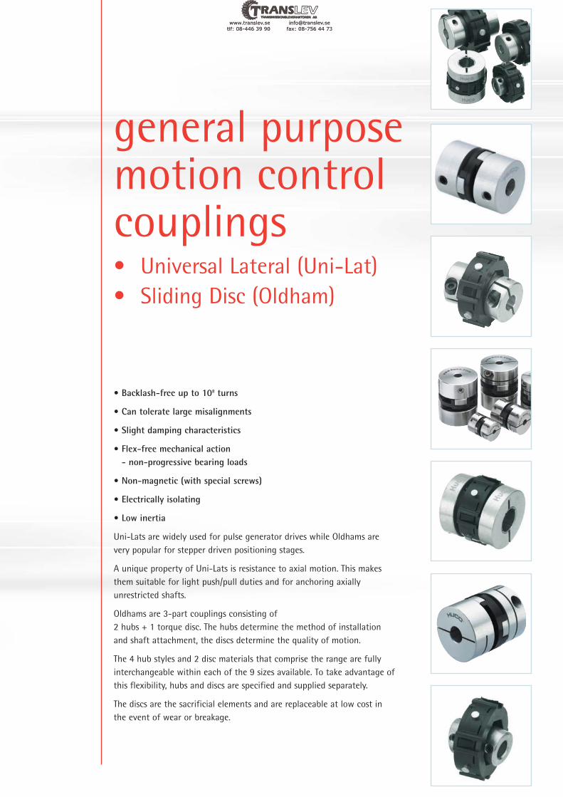
general purposemotion controlcouplings• Universal Lateral (Uni-Lat)
• Sliding Disc (Oldham)
• Backlash-free up to 108 turns
• Can tolerate large misalignments
• Slight damping characteristics
• Flex-free mechanical action- non-progressive bearing loads
• Non-magnetic (with special screws)
• Electrically isolating
• Low inertia
Uni-Lats are widely used for pulse generator drives while Oldhams are
very popular for stepper driven positioning stages.
A unique property of Uni-Lats is resistance to axial motion. This makes
them suitable for light push/pull duties and for anchoring axially
unrestricted shafts.
Oldhams are 3-part couplings consisting of
2 hubs + 1 torque disc. The hubs determine the method of installation
and shaft attachment, the discs determine the quality of motion.
The 4 hub styles and 2 disc materials that comprise the range are fully
interchangeable within each of the 9 sizes available. To take advantage of
this flexibility, hubs and discs are specified and supplied separately.
The discs are the sacrificial elements and are replaceable at low cost in
the event of wear or breakage.
www.translev.se [email protected]: 08-446 39 90 fax: 08-756 44 73
tlf: 08-
.twww -446 39 90
.seanslevtr fax: 08
info@ 8-756 44 73
.seanslev@tr 3

Uni-Lat Universal / Lateral Offset Couplings
+44 (0) 1992 501900
22
Ref. 201Small bores
Ref. 221 (not listed in main table).
Combines large & small bores.See explanatory note on facing page
Ref. 207Collet hub & ring clamp
Ref. 203Large bores
Ref. 205, 206Integral leaf clamp
Set screw hubs
Clamp hubs
Installation
Materials & Finishes Temperature Range
Typical
L1 L1L2
L2L1 L1 L2 L1L1
L L L
L L ØD
ØB1 ØB1
ØB1 ØB1ØB2 ØB2
ØB2
L1 L1L2
ØB1 ØB2 ØB2
Coupling ref. 221
Size L
18 16.7
27 22.3
34 28.0
41 33.3
Standard Uni-Lats cannot be used in pairs.
Special versions are available for use in this mode.
Please enquire.
wrongrightright
Up to 10° angular offset,
depending on type
Up to 1mm radial offset for
extreme misalignments
Hub sizes 18 & 27: Brass BS 2874 CZ121
Hub sizes 34 & 41: Al. Alloy AIECO 62Sn T9 Irridite NCP
Fasteners: Alloy steel, black oiled
Clamp rings (sizes 18 & 27):Al. Alloy AIECO 62Sn T9Irridite NCP
Torque rings, all sizes: Acetal (black)
–20°C to +60°C
C
19
www.translev.se [email protected]: 08-446 39 90 fax: 08-756 44 73
tlf: 08-
.twww -446 39 90
.seanslevtr fax: 08
info@ 8-756 44 73
.seanslev@tr 3

Uni-Lat Universal / Lateral Offset Couplings
23
www.huco.com
5.1
DIMENSIONS & ORDER CODESCoupling
Size
Set
Screw
Hubs
Clamp
Hubs
ØD L L1 L2 ØB1, ØB2
max
FastenersMoment
of inertiakgm2
x 10–8
ScrewTorque Wrench kg
x 10–3Nm mm
Mass
18
27
34
41
201.1818.0
14.2 4.6
6.9
8.9
11.2
5M3 0.94 1.5
2.0
1.5 91 16
2.5
2.0
2.5
3.0
2.0
220
165
476
183
550
26
17
30
20
40
20 7
19.1
19.1 6.1
25.4
25.2
28.4
8.1
8.6
10
10
12.7
12.7
30.7
38.1
10.9
13.5
12.7
16
9.3
7.04–40
M3
M3
M4
4–40
M4
M5
M4
2.3319.1
28.0
33.7
41.4
6.35
8
10
0.94
2.43
2.27
2.33
2.27
4.62
5.66
55 11
–
–
207.18 ‡ 219
–
–
207.27 ‡ 218
–
–
–
–
206.34
205.41
203.18
–
201.27
203.27
–
201.34
201.41
203.34
203.41
–
–
70 17.03.0
5.0
7315
7315
189
1892274.0 28.5
22 M6
M669.0
7.60
19.3
–
205.70
203.70
–
1 Length of supported thro’ bore. Shafts mustnot penetrate beyond L1 when in operation.
2 Nominal distance between shafts insertedto L1.
3 Maximum recommended tighteningtorque.
4 Values apply with max bores.
5 Peak torque. Select a size where PeakTorque exceeds the application torque x service factor. (see page 6)
6 Couplings can provide up to 1mm radialand 10° angular compensation (5° for ref. 207) when required. Observegiven values for maximum backlash-freelife. Electrical isolation between shafts >3kV for all models when offset ≤5°.
7 Values apply at 50% peak torque with nomisalignment, measured shaft-to-shaftwith largest standard bores.
8 Momentary values.
‡ Ref. 207 only. Insert both bore codes in
place of ‡.
Coupling ref. 221
By specifying ref. 221 (not listed in tables, see
diagram facing page) you can combine the
bores coded for ref. 201 with those coded for
ref. 203,
eg., 221.27.2432 specifies Size 27 with Ø6.35 x
10 bores.
1 2 4 4
3
ØB1, ØB2 +0.03/–0mm
3 3.175 4 4.763 5 6 6.350 7.938 8 9.525 10 12 12.700 14 15.875 16 18 19 19.05 20
Coupling
18
201.18
201.27
201.34
201.41
203.18
203.27
203.34
203.41
207.18
207.27
206.34
205.41
�
�
�
�
�
�
�
�
�
�
�
�
�
�
�
�
� �
�
�
�
�
�
�
�
�
�
�
�
�
�
�
�
�
�
�
�
�
�
�
�
�
�
�
�
�
�
�
�
�
�
�
�
�
�
�
�
�
� � �
14 16 18 19 20
251
22 24
253
27
254*
255
28 31 32
257
35 36 38
259
41 42 45 46 47 20
260 261
27
34
41
203.70
205.70
� � � � � � � � �
� � � � � � � � �70
Bore ref.
Corresponding
bore adaptor
STANDARD BORES
*
ref.size
COUPLING REF
Coupling
Size
18 0.3
2
0.2
0.2
0.25
0.25
0.25
2.3
0.6
0.4
0.19
0.19
25 19 155 0.9
5.0
7.5
10.5
68
92 31 350
146 34 300
299
1300
39
75
250
540
1.7
2.5
3.5
12.0
27
34
41
70
Peak
torque
Nm
Max compensation
@ 3000 r.p.m.
Angular
deg
Radial
mm
Axial
Rate
deg / Nm
Stiffness
Nm / rad
Max loading
±N
Stiffness
N / mm
Torsional Static break
torque
Nm
5 6
PERFORMANCE AT 20°C7
8
Diameters for which a bore adaptor is shown can be adapted to smaller shaft sizes. See page 56 for details.
*Note that adaptor 254 is dedicated to coupling ref. 201.27. Use adaptor 255 for all other 8mm diameters.
Load capacity depends on
application conditions:
see page 6 for details
IMPORTANT
20
C
www.translev.se [email protected]: 08-446 39 90 fax: 08-756 44 73
tlf: 08-
.twww -446 39 90
.seanslevtr fax: 08
info@ 8-756 44 73
.seanslev@tr 3

Oldham Lateral Offset Couplings
+44 (0) 1992 501900
24
Set screw style
Set screw style
Refs. 232, 243
Set screw style
Refs. 234, 235, 245
Clamp style
Refs. 450, 454
Set screw style
Refs. 452, 453, 456
Clamp style
Clamp style
Clamp style
Acetal – High torsional stiffness, good bearing properties, long
backlash-free life.
Nylon 11 – Resilient, isolates noise & vibration. Performanceapproximately 25% that of acetal disc.
Thro’ bored discs allow shafts to near-butt, standard thro’ hole
diameter = ØD x 0.5. To order, add suffix ‘T’ to order code, eg., 236.25T
Other thro’ hole diameters are manufactured to order. Specify the disc ref.
and thro’ hole diameter. This should equal the larger shaft
diameter + 2 x max radial error.
Note that thro’ bored discs reduce torsional stiffness.
Controlled bore depth L1
provides a register when pre-
assembling hubs to shafts
L1
ØD
ØD
Thro’ bores allow disc replacement
without disturbing shaft alignment
Standard discs (larger sizes are webbed) Thro’ bored discs
Materials & Finishes Temperature Range
Blind hubs
Blank hubs
Thro’ hubs
L
L1 L2
ØB
ØD
disc
ØB
L
L1 L2
disc
L
L1 L2
ØB
disc
User-adaptable for special needs, e.g. fitting within tubes. Blank
hubs are supplied centred with no provision for fastening.
External dimensions identical with blind hubs.
Complete hub ref. ØD L
06 231.06.00 6.4 12.7
09 231.09.00 9.5 12.7
13 231.13.00 12.7 15.9
19 231.19.00 19.1 22.0
25 231.25.00 25.4 28.4
33 230.33.00 33.3 48.0
33 231.33.00 33.3 42.0
41 231.41.00 41.3 50.8
L
L
L1 L2
ØB
disc
Coupling
size
Hub sizes 06 to 13: Brass BS 2874 CZ121
Hub sizes 19 to 57: Al. Alloy 2014A T6 orAIECO 62 Sn T9
Fasteners: Alloy steel, blackoiled
Blind & blank hubs: Irridite NCP finish
Thro’ hubs: Clear anodised finish
Torque discs: Types 236 - Acetal(black)Types 238 - Nylon 11(natural)
–20°C to +60°C
C
21
www.translev.se [email protected]: 08-446 39 90 fax: 08-756 44 73
tlf: 08-
.twww -446 39 90
.seanslevtr fax: 08
info@ 8-756 44 73
.seanslev@tr 3

Oldham Lateral Offset Couplings
25
www.huco.com
Coupling
Size
06 0.06
0.5
0.1
0.1
0.1
0.2
0.2
0.2
0.25
0.25
0.25
0.05 5.7
1.9
0.88
0.50
0.28
0.093
0.048
0.042
0.022
10
30
65
115
205
615
1200
1375
2610
0.7
2
4
8
13
53
57
95
150
0.05
0.05
0.1
0.1
0.15
0.15
0.2
0.2
0.21
0.5
1.7
4
9
17
30
44
09
13
19
25
33
41
50
57
Peak
torque
Nm
Max compensation
@ 3000 r.p.m.
Angular
deg
Radial
mm
Axial
± mm
Rate
deg / Nm
Stiffness
Nm / rad
Torsional Static break
torque
Nm
1 Blind hubs: Length of parallel bore ±0.2. Boresmay terminate in 118° incl. angle.Thro’ hubs: Max permissible hub penetration.
2 Blind hubs: Nominal distance betweenunchamfered shafts bottomed out to L1.Thro’ hubs: Nominal distance between shaftswith standard (unbored) disc.
3 Maximum recommended tightening torque (seealso next page under ‘Clamp hubs’)
4 Values apply to complete couplings with maxbores.
5 Peak torque. Select a size where Peak Torqueexceeds the application torque x service factor.
6 Couplings can provide up to (ØD x 0.1) radialcompensation in extreme cases.Observe given values for maximum backlash-free life.Axial compensation is set on installation. Seenext page for details.Electrical isolation between shafts > 3kV.
7 Values apply at 50% peak torque with nomisalignment, measured shaft-to-shaft withlargest standard bores.
8 Thro’ hubs can be provided with keyways or ‘D’bores. See page 56 for details.
5 6
PERFORMANCE (AT 20°C WITH STANDARD ACETAL DISC)7
Coupling
Type and
Size
Hub Ref Dimensions Fasteners Disc Ref
Set Screw
StyleClamp Style ØD L L1 L2 ØB1 Max
Moment of Inertia
kgm2x10-3
Mass kg
x10-3Size
Torque
(Nm)
Wrench
(mm)
Acetal
(black) Std.
Nylon 11
(Natural)
06 232.06 - 6.4 12.7 3.8 5.1 3.18 6 2.5 M3 0.94 1.5 236.06 238.06
09 232.09 - 9.5 12.7 3.8 5.1 5 18 4 M3 0.94 1.5 236.09 238.09
13 232.13 - 12.7 15.9 4.3 7.3 6.35 26 11 M3 0.94 1.5 236.13 238.13
19232.19 -
19.1 22.0 6.3 9.4 8 67 12M3 0.94 1.5
236.19 238.19- 235.19 4-40 2.33 2.0
25232.25 -
25.4 28.4 8.6 11.2 12 252 31M4 2.27 2.0
236.25 238.25- 234.25 M3 2.43 2.5
33
232.33 -33.3 42.0 13.0 16.0 16 1074 72
M5 4.62 1.5836.33 838.33
- 235.43 M4 2.33 2.0
243.33 -33.3 48.0 13.0 22.0 16 1278 86
M4 2.27 3.0236.33 238.33
- 245.33 M4 5.66 2.5
41232.41 -
41.3 50.8 16.7 17.4 20 3327 148M5 4.62 2.5
236.41 238.41- 234.41 M4 5.66 3.0
19450H19 -
19.1 26.0 9.4 7.2 8 59 13M5 4.62 2.5
236.19 238.19- 452H33 4-40 2.33 2.0
25450H25 -
25.4 32.4 11.6 9.2 12 252 31M5 4.62 2.5
236.25 238.25- 452H33 M3 2.43 2.5
33
450H33 -33.3 42.0 15.0 12.0 16 1080 67
M6 7.61 3.0836.33 838.33
- 452H33 M4 5.66 3.0
454H33 -33.3 48.0 15.0 18.0 16 1133 74
M6 7.61 3.0236.33 238.33
- 456H33 M4 5.66 3.0
41450H41 -
41.3 50.8 17.8 15.3 20 3177 142M6 7.61 3.0
236.41 238.41- 452H41 M4 5.66 3.0
50450H50 -
50.0 59.6 20.6 18.4 25.4 7550 208M8 18.36 4.0
236.50 -- 452H50 M5 11.40 4.0
57450H57 -
57.1 78.0 28.4 21.2 30 12410 361M8 18.36 4.0
236.57 -- 452H57 M6 19.34 5.0
DIMENSIONS & ORDER CODES
Blin
d H
ubs
Thro
’ Hub
s
1 2 4 4 3
For Standard Bores see page 26
NB. Size 33 available in both ‘standard’ and ‘long’ versions
Load capacity depends on
application conditions:
see page 6 for details
IMPORTANT
22
C
www.translev.se [email protected]: 08-446 39 90 fax: 08-756 44 73
tlf: 08-
.twww -446 39 90
.seanslevtr fax: 08
info@ 8-756 44 73
.seanslev@tr 3

Oldham Stainless Steel - thro’ hubs
+44 (0) 1992 501900
26
Size
Hub Ref Dimensions Fasteners Disc Ref
Set Screw
StyleClamp Style OD L L1 L2 OB1 Max
Moment of
Inertia
kgm2
x10-3
Mass kg
x10-3Size Torque (Nm)
A/F
(mm)
Acetal
(black) Std.
Nylon 11
(Nat)
25- 852.25
850.25 -25.4 32.4 11.6 9.2 12.0 587 76
M3 1.2 2.5
M5 2.1 2.5236.25 238.25
33- 852.33
850.33 -33.3 42.0 15.0 12.0 16.0 2091 165
M4 2.9 3.0
M6 3.8 3.0836.33 838.33
41- 852.41
850.41 -41.3 50.8 17.8 15.3 20.0 6822 305
M5 5.9 4.0
M6 3.8 3.0236.41 238.41
50- 852.50
850.50 -50.0 59.6 20.6 20.6 25.4 17368 510
M6 9.8 5.0
M8 9.0 4.0236.50 N/A
DIMENSIONS & ORDER CODES
PERFORMANCE
Materials & Finishes Temperature RangeHubs : Stainless Steel 303 S31 - Natural Finish
Fasteners: Stainless Steel
Discs: Torque disc details on page 24
–20°C to +60°C
Maximum Rotational Speed3000 rev/min
SizePeak Torque
(Nm)
Max compensation @ 3000 rev/min Torsional
Angular deg Radial mm Axial +/- mm Rate deg/Nm Stiff Nm/Rad
Static break torque
(Nm)
25 4
0.5
0.2 0.1 0.28 205 13
33 9 0.2 0.15 0.093 615 53
41 17 0.25 0.15 0.048 1200 57
50 30 0.25 0.12 0.042 1375 95
Set screw style
Ref. 850
Set screw style
Ref. 852
Clamp style
Clamp style
ØD
Thro’ bores allow disc replacement
without disturbing shaft alignment
Thro’ hubs
ØB
L
L1 L2
disc
L
L1 L2
ØB
disc
ØB +0.03/–0mm
2 3 3.175 4 4.763 5 6 6.350 8 9.525 10 12 12.700 14 15 15.875 16 18 19 19.050 20 24 25 30
Coupling
Size
06 � � �
� � � � �
� � � � � � �
� � � �
�
�
�
�
�
�
�
�
�
�
� �
�
�
�
�
�
�
�
�
�
�
�
� � � �
�
�
�
�
�
�
�
�
�
�
�
�
�
�
�
�
�
�
�
�
�
�
�
�
�
�
�
� �11 14 16 18 19 20 22 24 28 31 32 35 36 38 40 41 42 45 46 47 48 51 52 56
09
13
19
25
33
41
50
57
Bore ref.
STANDARD BORES8
C
23
www.translev.se [email protected]: 08-446 39 90 fax: 08-756 44 73
tlf: 08-
.twww -446 39 90
.seanslevtr fax: 08
info@ 8-756 44 73
.seanslev@tr 3

beamcouplings• Multi-Beam
• Single-Beam
• Step-Beam
• Torsionally rigid design
• Zero backlash
• No moving parts
• Single beam simple coupling compatible with industry
standard types
• 3-Beam single stage for increased torsional stiffness
• 6-Beam two stage for torsional stiffness and increased
radial compliance
• Step Beam for low inertia, electrical isolation, low cost
Beam couplings will readily accommodate any combination of
axial motion, angular and parallel misalignment.
The 3 start helical-cut design provides higher torque capability
and reduced wind-up compared with single beam versions.
Multi-Beam is available in three standard materials: stainless
steel, aluminium and acetal, for shaft diameters from 1mm to
38mm.
www.translev.se [email protected]: 08-446 39 90 fax: 08-756 44 73
tlf: 08-
.twww -446 39 90
.seanslevtr fax: 08
info@ 8-756 44 73
.seanslev@tr 3

Multi-Beam Stainless Steel Multi-Helix Flexible Beam Couplings
+44 (0) 1992 501900
28
10.0
Relieved
Ref. 721
3-Beam Relieved
Set screw hubs
Clamp hubs
8.0
4.0
4.0
720.09
12.7720.06
13
4.5
M310.0
6.35
5
5
5
5
5
Bore DiametersCoupling
Type
&Size
Set Screw
Style
Clamp
Style
9.5 14.2 2.0
12.7 19.1 6.0 3.0
3.0
6.0
4.764.0
8.0
15.9 20.3
19.1 22.9
6.5
6.5
25.4 31.8 9.0
31.8 44.5 12.0
5.0
6.0
3.18
5.0
14.0
M2.5
M3
M4
M4
M5
M6
M1.6
M2
M2.5
M2.5
M4
3
3 0.1
0.127
0.127
0.127
0.127
0.127
0.50
1.0
1.80
2.70
6.0
–
–
–
–
–
–
721.09
721.13
721.16
721.19
721.25
721.32
720.13
720.16
720.19
720.25
720.32
–
–
–
–
–
–
09
16
19
25
32
COUPLING REF ØD L
Min
B1
Min
B2
Max
B1 & B2
Set
Screw
Cap
Screw Angular
Offset
Deg.
Parallel
Offset
mm
Peak
Torque
Nm
21 2 3
6.4 3.2 1.0 2.0
3.0
3.0 M2 – 0.07 0.45–06
Ref. 702 : 6-Beam Non-Relieved
Ref. 722 : 6-Beam Relieved
Ref. 703 : 6-Beam Non-Relieved
Ref. 723 : 6-Beam Relieved
Typical
ØD
Typical
ØD
All 3-beam couplings are in
relieved form as standard.
See above drawings.
L1 L1
L
ØB1 ØB2
L1 L1
L
ØB1 ØB2
L1 L1
L
ØB1 ØB2
L1 L1
L
ØB1 ØB2
3-BEAM COUPLINGS: DIMENSIONS & ORDER CODES
Materials & Finishes
Temperature Range
Couplings: Stainless Steel 303 S31
Fasteners: Stainless Steel
–40°C to +140°C
BORE SIZES - SEE TABLE ON PAGE 32
C
25
www.translev.se [email protected]: 08-446 39 90 fax: 08-756 44 73
tlf: 08-
.twww -446 39 90
.seanslevtr fax: 08
info@ 8-756 44 73
.seanslev@tr 3

Multi-Beam Stainless Steel Multi-Helix Flexible Beam Couplings
29
www.huco.com
1.9
723.64 65.064
Non-R
elieved
7
7
7
7
7
7
7
7
Bore DiametersCouplingType
&Size
Set Screw
Style
Clamp
Style
09702.09 –
9.5
12.7
15.9
19.1
25.4
31.8
38.1
44.5
50.8
57.2
63.5
9.5
12.7
15.9
19.1
25.4
31.8
38.1
44.5
50.8
57.2
63.5
19.6
25.4
25.4
28.0
38.1
57.2
66.7
76.2
95.3
130.0
150.0
19.6
25.4
25.4
28.0
38.1
57.2
66.7
76.2
95.3
130.0
150.0
11.0
16.0
18.0
20.0
25.0
32.0
38.0
5.3
6.5
6.5
6.5
11.0
16.0
18.0
20.0
25.0
32.0
38.0
8.0
8.0
9.0
10.0
10.0
12.0
2.0
3.0
3.0
5.0
8.0
8.0
9.0
10.0
10.0
12.0
12.0
14.0
16.0
20.0
25.0
3.0
4.0
4.0
5.04.76
6.0
9.53
12.0
14.0
16.0
20.0
25.0
4.76
6.35
8.0
10.0
12.7
19.0
16.0
22.0
19.0
25.0
22.0
28.0
26.0
32.0
30.0
38.0
36.0
M2.5
M3
M4
M4
M5
M6
M6
M6
M8
M8
M8
5.0
5.3
6.5
6.5
6.5
2.0
3.0
3.0
4.0
5.0
6.0
6.354.76
8.0
10.0
4.76
6.35
8.0
10.0
12.7
19.0
16.0
22.0
19.0
25.0
22.0
28.0
26.0
32.0
30.0
38.0
36.0
M5
M6
M6
M6
M8
M8
M8
M3
M4
M5
M5
M6
M6
M8
M1.6
M2
M2.5
M2.5
M3
M4
M5
M5
M6
M6
M8
3
5
5
7
7
7
7
7
7
7
7
M2.5
M3
M4
M4
M1.6
M2
M2.5
M2.5
3
5
5
0.12
0.17
0.2
0.25
0.38
0.5
0.6
0.8
0.9
0.95
1.0
0.12
0.17
0.2
0.25
0.38
0.5
0.6
0.8
0.9
0.95
1.0
1.5
3.0
5.0
8.0
16.0
25.0
36.0
48.0
73.0
102.0
140.0
0.9
3.4
4.8
10.0
13.0
20.0
27.0
37.0
50.0
703.09
–
703.13
–
–
–
–
–
–
–
–
–
–
–
–
–
–
–
–
–
–
–
–
703.16
703.19
703.25
703.32
703.38
703.44
703.51
703.57
703.64
723.09
723.13
723.16
723.19
723.25
723.32
723.38
723.44
723.51
723.57
–
702.13
–
702.16
702.19
702.25
702.32
702.38
702.44
702.51
702.57
702.64
722.09
722.13
722.16
722.19
722.25
722.32
722.38
722.44
722.51
722.57
722.64
–
–
–
–
–
–
–
–
–
–
–
–
–
–
–
–
–
–
–
–
13
16
19
25
32
38
44
51
57
64
09
13
16
19
25
32
38
44
51
57
6-BEAM COUPLINGS: DIMENSIONS & ORDER CODES
COUPLING REF ØD L L1
Min
B1
Min
B2
Max
B1 & B2
Set
Screw
Cap
Screw Angular
Offset
Deg.
Parallel
Offset
mm
Peak
Torque
Nm
Relieved
1 2 2 3
1 Length of supported bore.
2 Max. compensation values are mutuallyexclusive.
3 Peak torque. Select a size where PeakTorque exceeds the application torquex service factor. (see page 6)
4 6-beam couplings only.If either shaft extends beneath thebeams, the area shown in blue must berelieved to provide clearance under theflexure.
If either shaft extends beneath
the beams, the area shown
outlined in red must be relievedto provide clearance under the
flexure.
Materials & Finishes
Temperature Range
Couplings: Stainless Steel 303 S31
Fasteners: Stainless Steel
–40°C to +140°C
BORE SIZES - SEE TABLE ON PAGE 33
Sizes 38 - 64 manufactured to order only
26
C
www.translev.se [email protected]: 08-446 39 90 fax: 08-756 44 73
tlf: 08-
.twww -446 39 90
.seanslevtr fax: 08
info@ 8-756 44 73
.seanslev@tr 3

Multi-Beam Aluminium Multi-Helix Flexible Beam Couplings
+44 (0) 1992 501900
30
6.0 6.0
Relieved
0.40
0.40
0.90
725.09
M310.0
6.35
5
5
5
5
5
Bore DiametersCoupling
Type
&Size
Set Screw
Style
Clamp
Style
9.5 14.2 4.5 2.0
12.7 19.1 6.0 3.0
3.0
4.0
4.0
4.764.0
6.0
8.0
15.9 20.3
19.1 22.9
6.5
6.5
25.4 31.8 9.0
31.8 44.5 12.0
5.0
3.18
5.0
8.0
14.0
M2.5
M3
M4
M4
M5
M6
M1.6
M2
M2.5
M2.5
M4
3
3 0.1
0.127
0.127
0.127
0.127
0.127
1.50
2.50
4.0
–
–
–
–
–
–
725.13
725.16
725.19
725.25
725.32
724.09
724.13
724.16
724.19
724.25
724.32
–
–
–
–
–
–
09
13
16
19
25
32
3-BEAM COUPLINGS: DIMENSIONS & ORDER CODES
COUPLING REF ØD L L1
Min
B1
Min
B2
Max
B1 & B2
Set
Screw
Cap
Screw Angular
Offset
Deg.
Parallel
Offset
mm
Peak
Torque
Nm
6.4 12.7 3.2 1.0 2.0
3.0
3.0 M2 – 0.07–724.0606
1 2 2 3
Ref. 724
3-Beam Relieved
Set screw hubs
Ref. 725
3-Beam Relieved
Clamp hubs
Typical
ØD
Typical
ØD
All 3-beam couplings are in
relieved form as standard.
See above drawings.
Ref. 706 : 6-Beam Non-Relieved
Ref. 726 : 6-Beam Relieved
Ref. 707 : 6-Beam Non-Relieved
Ref. 727 : 6-Beam Relieved
L1 L1
L
ØB1 ØB2
L1 L1
L
ØB1 ØB2
L1 L1
L
ØB1 ØB2
L1 L1
L
ØB1 ØB2
Materials & Finishes
Temperature Range
Couplings: Aluminium L168 orbetter
Fasteners: Alloy steel. black oiled
–40°C to +120°C
BORE SIZES - SEE TABLE ON PAGE 32
C
27
www.translev.se [email protected]: 08-446 39 90 fax: 08-756 44 73
tlf: 08-
.twww -446 39 90
.seanslevtr fax: 08
info@ 8-756 44 73
.seanslev@tr 3

Multi-Beam Aluminium Multi-Helix Flexible Beam Couplings
31
www.huco.com
Materials & Finishes
Temperature Range
Couplings: Aluminium L168 orbetter
Fasteners: Alloy steel. black oiled
–40°C to +120°C
38.0
Bore DiametersCoupling
Type
&Size
Set Screw
Style
Clamp
Style
09706.09 –
9.5
12.7
15.9
19.1
25.4
31.8
38.1
44.5
50.8
57.2
63.5
9.5
12.7
15.9
19.1
25.4
31.8
38.1
44.5
50.8
57.2
63.5
19.6
22.9
25.4
26.5
38.1
57.2
66.7
76.2
95.3
130.0
150.0
19.6
22.9
25.4
26.5
38.1
57.2
66.7
76.2
95.3
130.0
150.0
11.0
16.0
18.0
20.0
25.0
32.0
38.0
5.3
6.5
6.5
6.5
11.0
16.0
18.0
20.0
25.0
32.0
38.0
8.0
8.0
9.0
10.0
10.0
12.0
2.0
3.0
3.0
5.0
8.0
8.0
9.0
10.0
10.0
12.0
12.0
14.0
16.0
20.0
25.0
3.0
4.0
4.0
5.04.76
6.0
9.53
12.0
14.0
16.0
20.0
25.0
4.76
6.35
8.0
10.0
12.7
19.0
16.0
22.0
19.0
25.0
22.0
28.0
26.0
32.0
30.0
38.0
36.0
M2.5
M3
M4
M4
M5
M6
M6
M6
M8
M8
M8
5.0
5.3
6.5
6.5
6.5
2.0
3.0
3.0
4.0
5.0
6.0
6.354.76
8.0
10.0
4.76
6.35
8.0
10.0
12.7
19.0
16.0
22.0
19.0
25.0
22.0
28.0
26.0
32.0
30.0
38.0
36.0
M5
M6
M6
M6
M8
M8
M8
M3
M4
M5
M5
M6
M6
M8
M1.6
M2
M2.5
M2.5
M3
M4
M5
M5
M6
M6
M8
3
7
7
7
7
7
7
7
7
M2.5
M3
M4
M4
M1.6
M2
M2.5
M2.5
3
5
5
0.12
0.17
0.2
0.25
0.38
0.5
0.6
0.8
0.9
0.95
1.0
0.12
0.17
0.2
0.25
0.38
0.5
0.6
0.8
0.9
0.95
1.0
1.0
2.0
3.4
5.3
10.0
15.0
22.0
30.0
40.0
55.0
75.0
0.6
1.3
2.0
3.0
5.0
7.0
11.0
15.0
20.0
28.0
707.09
–
707.13
–
–
–
–
–
–
–
–
–
–
–
–
–
–
–
–
–
–
–
–
707.16
707.19
707.25
707.32
707.38
707.44
707.51
707.57
707.64
727.09
727.13
727.16
727.19
727.25
727.32
727.38
727.44
727.51
727.57
727.64
–
706.13
–
706.16
706.19
706.25
706.32
706.38
706.44
706.51
706.57
706.64
726.09
726.13
726.16
726.19
726.25
726.32
726.38
726.44
726.51
726.57
726.64
–
–
–
–
–
–
–
–
–
–
–
–
–
–
–
–
–
–
–
–
13
16
19
25
32
38
44
51
57
64
09
13
16
19
25
32
38
44
51
57
64
6-BEAM COUPLINGS: DIMENSIONS & ORDER CODES
COUPLING REF ØD L L1
Min
B1
Min
B2
Max
B1 & B2
Set
Screw
Cap
Screw Angular
Offset
Deg.
Parallel
Offset
mm
Peak
Torque
Nm
Non
-Rel
ieve
d
1 2 2 3
1 Length of supported bore.
2 Max. compensation values are mutuallyexclusive.
3 Peak torque. Select a size where PeakTorque exceeds the application torque xservice factor. (see page 6)
4 6-beam couplings only.If either shaft extends beneath thebeams, the area shown in blue must berelieved to provide clearance under theflexure.
Relie
ved
5
5
7
7
7
7
7
7
7
7
If either shaft extends beneath the
beams, the area shown outlined in
red must be relieved to provide
clearance under the flexure.
BORE SIZES - SEE TABLE ON PAGE 33
Sizes 38 - 64 manufactured to order only
28
C
www.translev.se [email protected]: 08-446 39 90 fax: 08-756 44 73
tlf: 08-
.twww -446 39 90
.seanslevtr fax: 08
info@ 8-756 44 73
.seanslev@tr 3

Multi-Beam Acetal Multi-Helix Flexible Beam Couplings
+44 (0) 1992 501900
32
2.50
Ref. 728
3-Beam Relieved
Ref. 729
3-Beam Relieved
Set screw hubs
Clamp hubs
Bore DiametersCoupling
Type
&Size
Set Screw
Style
Clamp
Style
13728.13 –
12.7
15.9
19.1
25.4
31.8
19.1
20.3
22.9
31.8
44.5 12.0
5.0
6.0
6.0
6.5
6.5
9.0
3.0
3.0
4.0
4.0
4.764.0
6.0
8.0
5.0
6.0
8.0
10.0
12.0
M5
M6
M3
M4
M3
M4
M4
M2
M2.5
M2.5
5
5
5
5
5
0.127
0.127
0.127
0.127
0.127
0.24
0.35
0.64
1.40
729.13
–
729.16
–
–
–
729.19
729.25
729.32
–
728.16
–
728.19
728.25
728.32
–
–
–
16
19
25
32
3-BEAM COUPLINGS: DIMENSIONS & ORDER CODES
COUPLING REF ØD L L1
Min
B1
Min
B2
Max
B1 & B2
Set
Screw
Cap
Screw Angular
Offset
Deg.
Parallel
Offset
mm
Peak
Torque
Nm
Rel
ieve
d
1 2 2 3
Typical
ØD
Typical
ØD
All 3-beam couplings are in
relieved form as standard.
See above drawings.
Ref. 710 : 6-Beam Non-Relieved
Ref. 730 : 6-Beam Relieved
Ref. 711 : 6-Beam Non-Relieved
Ref. 731 : 6-Beam Relieved
L1 L1
L
ØB1 ØB2
L1 L1
L
ØB1 ØB2
L1 L1
L
ØB1 ØB2
L1 L1
L
ØB1 ØB2
Materials & Finishes
Temperature Range
Couplings: Acetal (natural)
Fasteners: Stainless steel
–20°C to +60°C
� �B1 only B1 & B2
� Aluminium and
Stainless Steel Only
��� �
� �� � � � �� � �
���
��� �
���
��
��
�� � � �
� � �� �
08 11 14 16 18 19 20 22 24 28 31 32 35 36 38Bore ref.
BORE SIZES 3-BEAM COUPLINGSØB1, ØB2 +0.03/–0mm
1 2 3 3.175 4 4.763 5 6 6.350 8 9.525 10 12 12.700 14
Coupling
Size
09
06
13
16
19
25
32
C
29
www.translev.se [email protected]: 08-446 39 90 fax: 08-756 44 73
tlf: 08-
.twww -446 39 90
.seanslevtr fax: 08
info@ 8-756 44 73
.seanslev@tr 3

Multi-Beam Acetal Multi-Helix Flexible Beam Couplings
33
www.huco.com
� �B1 only B1 & B2
M6
6.5
6.5
6.5
7
7
7
13
Bore DiametersCoupling
Type
&Size
Set Screw
Style
Clamp
Style
13710.13 –
12.7
15.9
19.1
25.4
31.8
12.7
15.9
19.1
25.4
31.8
22.9
25.4
26.5
38.1
57.2
22.9
25.4
26.5
38.1
57.2
16.0
11.0
16.0
3.0
3.0
4.0
5.0
8.0
4.0
4.0
5.0
6.0
9.53
5.0
6.35
8.0
10.0
12.7
M3
M4
M4
M2.5
M2.5
M5 M3
M4
5.0
8.0
6.5
6.5
6.5
11.0
3.0
3.0
4.0
5.0
6.0
6.35
8.0
10.0
6.0
8.0
9.53
12.0
16.0
M5
M6
M3
M4
M2 5
5
7
7
7
M3
M4
M4
M2
M2.5
M2.5
5
5
0.17
0.2
0.25
0.38
0.5
0.17
0.2
0.25
0.38
0.5
0.51
0.91
1.3
2.5
4.0
0.32
0.61
0.87
1.67
2.4
711.13
–
711.16
–
–
–
–
–
–
–
–
711.19
711.25
711.32
731.13
731.16
731.19
731.25
731.32
–
710.16
–
710.19
710.25
710.32
730.13
730.16
730.19
730.25
730.32
–
–
–
–
–
–
–
–
16
19
25
32
16
19
25
32
6-BEAM COUPLINGS: DIMENSIONS & ORDER CODES
COUPLING REF ØD L L1
Min
B1
Min
B2
Max
B1 & B2
Set
Screw
Cap
Screw Angular
Offset
Deg.
Parallel
Offset
mm
Peak
Torque
Nm
Rel
ieve
dN
on-R
elie
ved
1 2 2 3
1 Length of supported bore.
2 Max. compensation values are mutuallyexclusive.
3 Peak torque. Select a size where PeakTorque exceeds the application torque
x service factor (see page 6).
4 6-beam couplings only.If either shaft extends beneath the
beams, the area shown in blue must be
relieved to provide clearance under the
flexure.
BORE SIZES 6-BEAM COUPLINGS NON-RELIEVED
Materials & Finishes
Temperature Range
Couplings: Acetal (natural)
Fasteners: Stainless steel
–20°C to +60°C
If either shaft extends beneath the
beams, the area shown outlined in
red must be relieved to provide
clearance under the flexure.
Size
9
2 3 3.175 4 4.763 5 6 6.35 8 9.525 10 12 12.7 14 15.88 16 18 19 19.05 20 24 25 25.4 28 30 31.75 32
� � � � �13 � � � � � � �16 � � � � � � � �19 � � � � � � �25 � � � � � � � �32 � � � � � � � �38 � � � � � � � � � � � �44 � � � � � � � � � � � � �51 � � � � � � � � � � � � � �57 � � � � � � � � � � � � � � � � �64 � � � � � � � � � � � � � � � �
Bore ref. 11 14 16 18 19 20 22 24 28 31 32 35 36 38 41 42 45 46 47 48 51 52 53 54 56 57 58
ØB1, ØB2 +0.03/-0mm
BORE SIZES 6-BEAM COUPLINGS RELIEVED
Size
9
2 3 3.175 4 4.763 5 6 6.35 8 9.525 10 12 12.7 14 15.88 16 18 19 19.05 20 24 25 25.4 28 30 31.75 32
� � � � �13 � � � � � � �16 � � � � � � � �19 � � � � � � �25 � � � � � � � �32 � � � � � � � �38 � � � � � � � � � � � �44 � � � � � � � � � � � � �51 � � � � � � � � � � � � � �57 � � � � � � � � � � � � � � � � �64 � � � � � � � � � � � � � � � �
Bore ref. 11 14 16 18 19 20 22 24 28 31 32 35 36 38 41 42 45 46 47 48 51 52 53 54 56 57 58
ØB1, ØB2 +0.03/-0mm
Aluminium and Stainless Steel Only�
30
C
www.translev.se [email protected]: 08-446 39 90 fax: 08-756 44 73
tlf: 08-
.twww -446 39 90
.seanslevtr fax: 08
info@ 8-756 44 73
.seanslev@tr 3

S-Beam Single Helix Beam Couplings - Stainless Steel
+44 (0) 1992 501900
34
Size
Set Screw
Style
Clamp
Style
O.D.O/A Length
L
Bore Depth
L1
Min
B1
Min
B2
Max
B1 & B2
Mass kg
x 10-3Set Screw Cap Screw
Torque
(Nm)
A/F
(mm)
Dimensions Fasteners
16820.16
-
-
821.1615.9
20
22
6.0
6.53 4 6.35
25.6
26.0
M4
-
-
M2.5
1.05
0.68
2.0
2.0
19820.19
-
-
821.1919.1
20
28
6.0
8.04 4.76 8
35.8
47.7
M4
-
-
M2.5
1.05
0.68
2.0
2.0
25820.25
-
-
821.2525.4
24
30
7.5
10.05 6 10
78
91
M5
-
-
M3
2.10
1.20
2.5
2.5
32820.32
-
-
821.3231.8
30
38
10.0
12.06 8 16
152
186
M6
-
-
M4
3.75
2.85
3.0
3.0
38820.38
-
-
821.3838.1
50
50
16.0
16.08 12 19
365
350
M6
-
-
M5
3.75
5.85
3.0
4.0
50820.50
-
-
821.5050.8
54
54
18.0
18.010 16 26
680
660
M8
-
-
M6
9.00
9.75
4.0
5.0
DIMENSIONS & ORDER CODES
Size
Size
16
+0.03/-0mm
3 3.175 4 4.763 5 6 6.350 7.938 8 9 9.525 10 12 12.700 14 15 15.875 16 19.050 20 24 25
Peak
Torque
(Nm) Angular deg Radial mm Axial mm BoreTorsional
Nm/rad
Max misalignment compensation Nominal stiffness at std. bore size
PERFORMANCE
AVAILABLE BORES
16 1.2 5 0.25 0.25 5 16
19 2.3 5 0.25 0.25 6 33
25 4.3 5 0.25 0.25 10 45
32 7.8 5 0.25 0.25 12 84
38 20 5 0.25 0.25 16 195
50 30 5 0.25 0.25 20 320
Materials & Finishes
Temperature Range
Set Screw Hubs Clamp Hubs
Couplings: Stainless Steel 303 S31
Fasteners: Stainless Steel
–40°C to +140°C
� � � � � � �19 � � � � � �25 � � � � � � � �32 � � � � � � � � � � � �38 � � � � � � � �50 � � � � � � � � �
Bore Ref 14 16 18 19 20 22 24 27 28 30 31 32 35 36 38 40 41 42 47 48 52 53
� �B1 only B1 & B2
Order Code
C
31
www.translev.se [email protected]: 08-446 39 90 fax: 08-756 44 73
tlf: 08-
.twww -446 39 90
.seanslevtr fax: 08
info@ 8-756 44 73
.seanslev@tr 3

35
www.huco.com
S-Beam Single Helix Beam Couplings - Aluminium
Size
Set Screw
Style
Clamp
Style
O.D.O/A Length
L
Bore Depth
L1
Min
B1
Min
B2
Max
B1 & B2
Mass kg
x 10-3Set Screw Cap Screw
Torque
(Nm)
A/F
(mm)
Dimensions Fasteners
16826.16
-
-
827.1615.9
20
22
6.0
6.53 4 6.35
8.8
9.8
M4
-
-
M2.5
2.27
1.32
2.0
2.0
19826.19
-
-
827.1919.1
20
28
6.0
8.04 4.76 8
13.1
17.3
M4
-
-
M2.5
2.27
1.32
2.0
2.0
25826.25
-
-
827.2525.4
24
30
7.5
10.05 6 10
28
33
M5
-
-
M3
4.62
2.43
2.5
2.5
32826.32
-
-
827.3231.8
30
38
10.0
12.06 8 16
55
67
M6
-
-
M4
7.61
5.66
3.0
3.0
38826.38
-
-
827.3838.1
50
50
16.0
16.08 12 19
127
130
M6
-
-
M5
7.61
11.40
3.0
4.0
50826.50
-
-
827.5050.8
54
54
18.0
18.010 16 26
241
237
M8
-
-
M6
18.36
19.34
4.0
5.0
DIMENSIONS & ORDER CODES
Size
Peak
Torque
(Nm) Angular deg Radial mm Axial mm BoreTorsional
Nm/rad
Max misalignment compensation Nominal stiffness at std. bore size
PERFORMANCE
16 0.6 5 0.25 0.25 5 6
19 1.1 5 0.25 0.25 6 12
25 2.2 5 0.25 0.25 10 17
32 4.1 5 0.25 0.25 12 32
38 10 5 0.25 0.25 16 70
50 15 5 0.25 0.25 20 119
Materials & Finishes
Temperature Range
Couplings: Aluminium L 168 or better
Fasteners: Alloy steel, black oiled
–40°C to +120°C
Set Screw Hubs Clamp Hubs
Size
16
+0.03/-0mm
3 3.175 4 4.763 5 6 6.350 7.938 8 9 9.525 10 12 12.700 14 15 15.875 16 19.050 20 24 25
AVAILABLE BORES
� � � � � � �19 � � � � � �25 � � � � � � � �32 � � � � � � � � � � � �38 � � � � � � � �50 � � � � � � � � �
Bore Ref 14 16 18 19 20 22 24 27 28 30 31 32 35 36 38 40 41 42 47 48 52 53
� �B1 only B1 & B2
Order Code
32
C
www.translev.se [email protected]: 08-446 39 90 fax: 08-756 44 73
tlf: 08-
.twww -446 39 90
.seanslevtr fax: 08
info@ 8-756 44 73
.seanslev@tr 3

Step-Beam Step Beam Couplings - Nylon
+44 (0) 1992 501900
36
Size
Set Screw
Style
Clamp
Style
O.D.O/A Length
L
Max Shaft
Depth L1
Min
Bore
Max
Bore
Mass kg
x 10-3Set Screw Cap Screw
Torque
(Ncm)
A/F
(mm)
Dimensions Fasteners
13636.13
-
-
637.1613 18 5.0 3 6.35 3.0
M2
-
-
M2
0.08
0.23
0.9
1.5
19636.19
-
-
637.1919 28 8.0 3 9.53 7.5
M3
-
-
M2.5
0.32
0.51
1.5
2.0
25636.25
-
-
637.2525 36 10.0 6 12.7 17.4
M4
-
-
M3
1.05
0.90
2.0
2.5
DIMENSIONS & ORDER CODES
Size
Size
13
+0.05/-0mm
3 3.175 4 4.763 5 6 6.350 7.938 8 9.525 10 12 12.700
Peak
Torque
(Nm)
Torsional
Stiffness
(Nm/rad) Angular deg Radial mm Axial mm
Max misalignment / displacement
PERFORMANCE
AVAILABLE BORES
13 0.25 5.5 3 0.15 0.2
19 0.8 12.0 4 0.15 0.2
25 2.5 18.0 5 0.3 0.3
� � � � � � �19 � � � � � � � �25 � � � � � � �
Bore Ref 14 16 18 19 20 22 24 27 28 31 32 35 36
Materials & Finishes Temperature RangeCouplings: Nylon type engineering polymer
Fasteners: Stainless Steel
–20°C to +150°C
Set Screw Hubs Clamp Hubs
Order Code
C
33
www.translev.se [email protected]: 08-446 39 90 fax: 08-756 44 73
tlf: 08-
.twww -446 39 90
.seanslevtr fax: 08
info@ 8-756 44 73
.seanslev@tr 3

drive couplings• Flexible Double Loop
• Flexible Jaw (Spider)
• Magnetic
General purpose couplings for light power drives.
www.translev.se [email protected]: 08-446 39 90 fax: 08-756 44 73
tlf: 08-
.twww -446 39 90
.seanslevtr fax: 08
info@ 8-756 44 73
.seanslev@tr 3

Flex - G Flexible Jaw Coupling
+44 (0) 1992 501900
38
Huco Flexible Jaw Couplings utilise the flexibility and resilience of a
polyurethane element between aluminium hubs. This combination
allows high torque to be transmitted with little or no back-lash, even
where there is significant angular and/or parallel misalignment.
• Zero / Low backlash
• Rated up to 17Nm Torque
• Choice of 3 polyurethane elements
User-adaptable for special needs e.g. fitting within tubes.
Blank hubs are supplied centred with no provision for
fastening. External dimensions identical with blind hubs.
Except size 40 which has 6.35 pilot hole.
Polyurethane elements are available with three hardness
levels; hard, standard and soft which exhibit different
operating characteristics. Other features of polyurethane are:
• Resistance to oils, grease and many solvents
• Good atmospheric and chemical resistance
• Excellent shock and vibration damping
Set Screw Hubs
Pilot Hubs
Elements
Thro’ Clamp Hubs
C
35
www.translev.se [email protected]: 08-446 39 90 fax: 08-756 44 73
tlf: 08-
.twww -446 39 90
.seanslevtr fax: 08
info@ 8-756 44 73
.seanslev@tr 3

Flex - G Flexible Jaw Coupling
39
www.huco.com
Coupling
Size
Set Screw
Style
Clamping
Style
Pilot
Hub
ØD L L1
1
L2 ØB1 max
6
Fasteners 2
Screw Torque
Nm
Wrench
mm
Moment
of inertia
kgm2
x 10-83
Mass
kg
x 10-33
Soft
(Blue)
Med
(White)
Hard
(Red)
ELEMENT REFHUB REF
14
802.14 - -
- 803.14 -
- - 800.14
14.0 22.0 7.0 8.0 6.35
M3 0.94 1.5
M2.5 1.32 2.5
- - -
18.4 7.0 804.14 805.14 806.14
20
802.20 - -
- 803.20 -
- - 800.20
20.0 30.0 10.0 10.0 9.0
M3 0.94 1.5
M3 2.43 2.5
- - -
106.0 17.0 804.20 805.20 806.20
30
802.30 - -
- 803.30 -
- - 800.30
30.0 35.0 11.0 13.0 14.0
M4 2.27 2.0
M3 2.43 2.5
- - -
606.0 51.0 804.30 805.30 806.30
40
802.40 - -
- 803.40 -
- - 800.40
40.0 66.0 25.0 16.0 16.0
M5 4.62 2.5
M4 5.66 3.0
- - -
4230.0 108.0 804.40 805.40 806.40
DIMENSIONS & ORDER CODES
PERFORMANCE (AT 20ºC)
Coupling
Size
Spider
Rigidity
Duro7
Angular
deg
Radial
mm
Misalignment Speed
R.P.M
max
Rate
deg/Nm
Stiffness
Nm/rad
Torsional 5 BacklashFree
Torque
Nm
TorqueNominal
4
Nm
TorqueMax
Nm
14
80 Blue
92 White
98 Red
2 0.10 40000
6.7
3.9
2.29
8.5
14.7
25.0
0.22
0.67
1.12
1.90
1.34
2.24
3.80
20
80 Blue
92 White
98 Red
2 0.15 28000
3.37
2.05
1.22
17
28
47
0.45
1.80
2.93
4.85
3.60
6.00
9.70
30
80 Blue
92 White
98 Red
2 0.20 19000
1.24
0.40
0.25
71
143
228
1.00
3.95
7.33
12.40
7.90
14.60
24.80
40
80 Blue
92 White
98 Red
2 0.38 14000
0.34
0.17
0.10
170
344
573
2.40
4.85
9.80
16.70
9.70
19.60
33.40
1 Maximum permissable hub penetration
2 Maximum recommended tightening torque
3 Values apply to complete couplings with max. bores
4 Nominal Torque. Select a size where Nominal Torque exceedsapplication torque x service factor (see page 6)
5 Values apply at 50% nominal torque, measured shaft to shaftwith largest standard bores
6 Hubs can be provided with keyways or 'D’ bores
7 Spider Durometer is shore ‘A’ hardness
Coupling
Size3 3.175 4 4.763 5 6 6.350 8 9.525
+0.03/-0mm
10 12 12.700 14 15 15.875 16
14 � � � � � � �20 � � � � �30 � � � � � � � �40 � � � � � � � � �
Bore ref. 14 16 18 19 20 22 24 28 31 32 35 36 38 40 41 42
STANDARD BORES
Materials & FinishesHub sizes 14 - 30: Al. Alloy 2024
Hub size 40: Cast Aluminium LM9
Membranes: Polyurethane
Fastener: Alloy steel, black oiled
-40ºC to +80ºC
For short durations up to 100ºC
Temperature Range
36
C
www.translev.se [email protected]: 08-446 39 90 fax: 08-756 44 73
tlf: 08-
.twww -446 39 90
.seanslevtr fax: 08
info@ 8-756 44 73
.seanslev@tr 3

Flex - P Double Loop Flexible Coupling
+44 (0) 1992 501900
40
SizeMax Diameter
Length L
+/- 1.0Bore length Max Bores Mass kg x 10-3 Size Torque (Nm)
A/F
(mm)
Dimensions Fasteners
DIMENSIONS & ORDER CODES
PERFORMANCE
10047.10
- 049.10
-27 27 7.9 9.53 25 M3
0.32
0.941.5
20047.20
- 049.20
-48 48 12.7 12.7 92 M4
2.0
2.272.0
30047.30
- 049.30
-54 55 16.0 16.0 124 M5
2.1
4.622.5
40047.40
- 049.40
-56 56 16.0 16.0 136 M6
3.75
7.613.0
40* - 050.40 56 56 16.0 16.0 136 M6 7.61 3.0
SizeMax Torque 1
(Nm)
Max Torque 2
(Nm)
max misalignment/displacement
Angular deg Radial mm Axial +/- mm
10 0.5 0.8 10 2.6 4.5
20 1.8 3 15 3.2 7.5
30 5 8 15 3.2 8.5
40 10 18 15 3.2 11
40* 2.5 4.5 15 3.2 11
Torque 1 = torque at maximum displacement
Torque 2 = torque at 1 deg. angular, 2mm axial and 0.5mm radial displacement
* Couplings with dissimilar bores are non-standard
STANDARD BORES*
Size+0.05/-0mm
3 3.175 4 4.763 5 6 6.350 7.938 8 9.525 10 12 12.700 14 15 15.875 16
10 � � � � � � � � � � �20 � � � � � � � �30 � � � � � � � �40 � � � � � � � �
Bore Ref 14 16 18 19 20 22 24 27 28 31 32 35 36 38 40 41 42
Materials & Finishes
Temperature Range
Hubs: Steel 230M07 pb Zn plated + clear passivate
or
Stainless Steel 303 S31 natural finish
Flexing Element: Hytrel
Fastener: Steel Hub: Alloy steel, black oiled
Stainless Steel Hub: stainless steel
–40°C to +100°C
Maximum Rotational Speed3000 rev/min
steel zinc
plated hubs
stainless steel
hubs
Order Code
C
37
www.translev.se [email protected]: 08-446 39 90 fax: 08-756 44 73
tlf: 08-
.twww -446 39 90
.seanslevtr fax: 08
info@ 8-756 44 73
.seanslev@tr 3

Mag-link Magnetic Disc Coupling
41
www.huco.com
DIMENSIONS & ORDER CODES
*half coupling ** metric bores supplied with metric screws
PERFORMANCE
Size
Max
Running
Torque
(Nm)
Slip
Torque
(Nm)
max misalignment/displacement
Angular deg Radial mm
40 0.34 0.45 3 6.35
50 0.68 0.79 3 6.35
60 1.02 1.13 3 6.35
70 1.81 2.15 3 6.35
Also available unbored - use bore code 0000
STANDARD BORES
Size+0.05/-0mm
3.175
40 �50
60
70
Bore Ref 14
5
�
20
6
�
�
122
6.35
�
�
24
7.938
�
�
27
10
�
32
11
�
�
33
12.7
�
�
�36
14
�
�38
15.875
�
�42
19
�
�46
19.05
�
�47
22.225
�50
25.4
�53
SizeStainless Steel Hub
O.D.O/A
LengthL
Recommended
Air Gap
Hub Length
L1
Hub Dia
DMax Bore
Mass* kg
x 10-3
Size Metric
Inch**Torque (Nm)
A/F (mm)
inchOrder Code
Dimensions Fasteners
40 MTD.40 44 35 4.75 15.0 20.6 8 0.11#8-32 0.95 5/64
M4 1.05 2.0
50 MTD.50 50 35 4.75 15.0 28.5 12.7 0.17#10-32 2 3/32
M5 2.1 2.5
60 MTD.60 60 43 4.75 19.8 38.1 19.0 0.30#10-32 2 3/32
M5 2.1 2.5
70 MTD.70 73 56 4.75 25.4 51.0 25.4 0.58#10-32 2 3/32
M5 2.1 2.5
7.0
70
60
50
40
6.0
5.0
4.0
3.0
2.0
1.0
0.0
0 2 4 6 8
TORQUE VS. AIR GAP
Torq
ue (
Nm
)
Air Gap (mm)
• High Energy Rare Earth Magnets
• Smooth Running
• Overload protection to 110%
• Torsionally soft
• Electrical / Mechanical / Chemical
isolation
• Stainless Steel Hubs Type 416
38
C
www.translev.se [email protected]: 08-446 39 90 fax: 08-756 44 73
tlf: 08-
.twww -446 39 90
.seanslevtr fax: 08
info@ 8-756 44 73
.seanslev@tr 3

plastic universaljoints andteleshafts
• Backlash-free up to 108 turns
• Low mass
• Low inertia
• Corrosion resistant
• Electrically isolating
• No maintenance
Huco-Pol is a range of light duty, backlash-free universal joints and
teleshafts manufactured of acetal and non-ferrous metals.
They are suitable for intermittent applications where low mass,
corrosion resistance and electrical isolation are desirable.
Huco-Pol joints and teleshafts have only a fraction of the torque
capability of steel joints and are not intended to substitute for these
in the normal way.
Huco-Pols are used in business machines, food processing plant,
laboratory equipment and electro-medical apparatus among others.
Alternative polymers are available for high temperature operation.
www.translev.se [email protected]: 08-446 39 90 fax: 08-756 44 73
tlf: 08-
.twww -446 39 90
.seanslevtr fax: 08
info@ 8-756 44 73
.seanslev@tr 3

Huco - Pol Plastic Universal Joints
+44 (0) 1992 501900
44
SINGLE JOINTS - DIMENSIONS & ORDER CODES
Size
Size Peak Torque
Nm
Static Break
Torque Nm
Torsional Rate
deg/Nm
Torsional
Stiffness
Nm/Rad
Peak Torque
Nm
Static Break
Torque Nm
Torsional Rate
deg/Nm
Torsional
Stiffness
Nm/Rad
Max
angular
compensation
@
1000 rev/min
Max axial
loading N
Brass Cross-piece 101, 103, 105 Plastic Cross-piece 601, 603
Brass
Cross-piece
Plastic
Cross-pieceOD L L1 L2 L3
B1, B2
Max
Moment of
inertia kgm2
x 10-8
Mass kg
x 10-3Size
Torque
(Nm)
A/F
(mm)
Dimensions Fasteners
06
-
103.06
-
101.06
603.06
-
601.06
-
7.1
27.2
19.1
-
3.3
9.3
8.6
3.181.0
1.1
0.3 0.7-4.76
0.2
2.8
3.1M3
-
0.94
-
1.5
0.45.3
09
-
103.09
-
101.09
603.09
-
601.09
-
11.1
37.6
28.5
-
4.3
13.1
11.4
5.012.6
13.5
4.0 2.7-6.35
4.0
8.1
9.3M3
-
0.94
-
1.5
1.58.6
13
-
103.13
-
101.13
603.13
-
601.13
-
14.3
46.2
35.6
-
5.6
15.7
14.8
6.3538.0
44.6
14.3 5.7-8.0
11.9
15.6
17.7M3
-
0.94
-
1.5
3.610.4
16
20 105.20 - 23.0 62.0 8.0 17.0 28.0 12.7 147 25.7 - - -
25 105.25 - 28.5 74.0 10.0 20.0 34.0 14 463 56 - - -
32 105.32 - 36.5 86.0 10.0 21.0 44.0 20 1339 103 - - -
-
103.16
-
101.16
603.16
-
601.16
-
17.5
67.6
53.3
-
8.9
22.3
23.0
10.0122
136
32.3 12.2-11.0
18.3
31.4
35.0M4
-
2.27
-
2.0
5.015.2
SINGLE JOINTS - PERFORMANCE (at 20ºC)
06 0.11 0.45 19.7 2.9 0.09 0.3 22 2.6 45 18
09 0.36 1.9 6.8 8.4 0.6 1.5 6.8 8.4 45 38
13 0.85 4.5 3.2 18 0.7 2.5 3.6 16.0 45 67
16 1.6 6.8 1.7 34 1.0 5.0 2.8 20.0 45 98
20 2.8 17 0.94 61 - - - - 40 138
25 5.6 34 0.51 112 - - - - 40 222
32 10.7 72 0.25 229 - - - - 40 334
FOR STANDARD BORES SEE FACING PAGE
Materials & FinishesBodies: Acetal
Cross-pieces: Brass BS 2874 CZ121 (101, 103, 109, 111)
Nylon Glass filled (601, 603, 609, 611)
Bore Inserts: Brass BS 2874 CZ121 (103, 111, 603, 611)
Al. Alloy 2014A T6 or AIECO 62 Sn T9 (105)
Fasteners: Alloy steel, black oiled
- 20ºC to +60ºC
Operating Temperature Range
1000 rev/min
Maximum Rotational Speed
Type 101, 105, 601 Type 103, 603
ØB1 ØB2
L
L1
L2
ØB1 ØB2
L
L2L2L3 L2L3
Hub Ref
1 2
1 2
40
C
www.translev.se [email protected]: 08-446 39 90 fax: 08-756 44 73
tlf: 08-
.twww -446 39 90
.seanslevtr fax: 08
info@ 8-756 44 73
.seanslev@tr 3
Se även Kapitel I sid. 1-9

Huco - Pol Plastic Universal Joints
45
www.huco.com
DOUBLE JOINTS - DIMENSIONS & ORDER CODES
Size
Size
06
3 3.175 4 4.763 5 6 6.350 8 9.525 10 12 12.700 14 15.875 16 18 19 19.050 20
Bore tolerences 101, 601, 109, 609 = +0.04/-0.0mm • 103, 603, 111, 611 = +0.03/-0.0mm
Peak Torque
Nm
Static Break
Torque Nm
Torsional Rate
deg/Nm
Torsional
Stiffness
Nm/Rad
Peak Torque
Nm
Static Break
Torque Nm
Torsional Rate
deg/Nm
Torsional
Stiffness
Nm/Rad
Max
angular
compensation
@
1000 rev/min
Max radial
compensation
mm
Brass Cross-piece 109, 111 Plastic Cross-piece 609, 611
SINGLE JOINTS - PERFORMANCE (at 20ºC)
STANDARD BORES
06 0.08 0.34 81.9 0.7 0.08 0.3 115 0.5 90 5.6
09 0.16 1.9 13.3 4.3 0.16 1.5 17.3 3.3 90 9.1
13 0.59 3.4 8.1 7.1 0.59 2.5 10.4 5.5 90 10.9
16 1.3 6.8 4.5 12.6 1.0 5.0 7.5 7.6 90 15.5
SizeOD L L1 L2 L3 L4 B1, B2 Max
Moment of
inertia
kgm2
x 10-8
Mass kg
x 10-3Size
Torque
(Nm)
A/F
(mm)
Dimensions Fasteners
06
-
111.06
-
109.06
611.06
7.1
35.3
27.2
-
3.3
9.3
5.3
16.7 8.1
3.181.1
1.3
4.760.4
0.6
3.0
3.5M3
0.6
1.1-
0.94
-
1.5
-
-
609.06
-
09
-
111.09
-
109.09
611.09
11.1
50.8
41.7
-
4.3
13.1
8.6
24.6 13.2
5.014.0
15.3
6.355.8
5.9
8.6
11.1M3
2.0
4.5-
0.94
-
1.5
-
-
609.09
-
13
-
111.13
-
109.13
611.13
14.3
62.1
51.4
-
5.6
15.7
10.4
30.7 15.9
6.3550.4
50.4
8.021.5
23.7
15.6
21.6M3
7.5
9.6-
0.94
-
1.5
-
-
609.13
-
16
-
111.16
-
109.16
611.16
17.5
89.8
75.5
-
8.9
22.3
15.2
45.2 22.2
10.0150.0
178.0
11.035.5
63.5
35.2
42.4M4
12.5
19.7-
2.27
-
2.0
-
-
609.16
-
� � � �09 � � � � � � �13 � � � � � �16 � � � � �20 � � � �25 � � �32 � � � � � � �
Bore Ref 14 16 18 19 20 22 24 28 31 32 35 36 38 41 42 45 46 47 48
� Moulded bores only � Sleeved bores only � Moulded or sleeved bores available
Type 109, 609 Type 111, 611
ØB1 ØB2
L
L1
L2
ØB1 ØB2
L
L2L3 L2
L4
L2L3
L4
Plastic
Cross-piece
Brass
Cross-piece
Hub Ref
1
1 2
2
C
41
www.translev.se [email protected]: 08-446 39 90 fax: 08-756 44 73
tlf: 08-
.twww -446 39 90
.seanslevtr fax: 08
info@ 8-756 44 73
.seanslev@tr 3
Se även Kapitel I sid. 1-9

Huco - Pol Plastic Universal Joints
+44 (0) 1992 501900
46
Constant velocityThe velocity ratio of single universal joints is not constant when the working
angle is greater than zero. Their geometry gives rise to sinusoidal
fluctuations at the output that increase with the working angle and which
vary between:
ω cos β and ω sec βwhere ω = angular velocity
and β = operating angle
For example, when the operating angle is 5°, the maximum error is ±0.4%;
at 7° it is ±0.8%, and at 10° it is ±1.5%. A motor shaft turning at a
constant 1000 rpm, driving through a single universal joint set at an
operating angle of 5°, produces an output that fluctuates between 996 rpm
and 1004 rpm twice each revolution.
The fluctuations are cancelled out when using a double joint or two single
joints connected back to back.
To maintain constant velocity ratio, ensure that:
a) The orientation of two single joints is correct; the inboard forks should align
as in double joints.
b) The working angle of both joints, or both halves of a double joint, is the
same.
β1
β1
β2noteorientation
noteorientation
β2
ADJUSTED TORQUE
Peak torque values apply when the working angle is zero. Adjusted torque takes account of dynamic loading at the bearings. To find adjusted torque, determine
application speed, torque and operating angle,
Then:
a) multiply speed x working angle
b) subtract the result from 10000
c) divide the answer into 10000
d) apply the result to the application torque.
eg. speed = 400 rpm
application torque = 0.1Nm
working angle = 20°
Accordingly:
a) 400 rpm x 20° = 8000
b) 10000 – 8000 = 2000
c) 10000 / 2000 = 5
d) 5 x 0.1Nm = 0.5Nm
Select a joint where Peak Torque exceeds 0.5Nm, ie., size 13 or larger.
Note: To remain within the capacity of the joint, the result of speed x working angle must be less than 10000.
42
C
www.translev.se [email protected]: 08-446 39 90 fax: 08-756 44 73
tlf: 08-
.twww -446 39 90
.seanslevtr fax: 08
info@ 8-756 44 73
.seanslev@tr 3
Se även Kapitel I sid. 1-9

Huco Teleshafts Plastic Universal Joints, Brass Cross Pieces & Tubes
47
www.huco.com
20
25
Teleshaft
size
STANDARD BORES
09
13
16
20
25
32
Refs. 128 & 495Joints sleeved with headed brass inserts fitted 2 screws per endEnd A
(inner tube)
End B
(outer tube)
Refs. 130 & 497Joints sleeved with metal inserts. Attach to shafts by cross-pinning or bonding
ØB2ØB1
L min / L max
L2 L2
Teleshafts are delivered with
nose bush parked here*Nose bush optional.
Bond in place after cutting tube to length
S
S
ØB2ØB1
L min / L max
L2 L2S
S
Typical
ØD
Teleshaft
size
Teleshaft options Corresponding joints.
For dimensions
see
Standard tubes
self-colour brass
Wear-resistant tubes
Niflor coated
ØD L L Stroke L2 ØB1, ØB2
max
Mass
ØB1, ØB2 +0.03 / –0mm
3.175 4 4.763 5 6 6.350 8 9.525 10 12 12.700 15.875 16 19.050 20
�
�
�
� �
� �
�
�
�
� � �
�
�
�
� �
� � � �
16 18 19 20 22 24 28 31 32 35 36 41 42 47 48
251 253 255 257 259 260 261
Bore ref.
Corresponding
bore adaptor
DIMENSIONS & ORDER CODES
Diameters for which a bore adaptor is shown can be adapted to smaller shaft sizes. See page 56 for details.
• A range of standard telescopes is available which can be shortened to achieve an infinite number of length/stroke
requirements. The lengths L min shown in the table above are the longest of the standard range in each size. Specific
lengths are produced by cutting an equal amount from both ends of the nearest standard size. See next page for
recommended procedure.
• Custom Teleshaft assemblies can be factory made subject to minimum order quantities.
• *The nose bush eliminates any torsional free play that may be apparent in the tubes due to working clearances.
• Full details of the standard range and product order codes are available on request. Please ask for a Huco Teleshaft
data sheet.
1 Niflor is a proprietory PTFE impregnatedelectroless nickel plating process.
2 Max shaft penetration
3 Values apply with max bores.
kg
x 10–3±1.0
min max S
09
128.13.300
128.09.240
495.13.300
495.09.240 11.1
300
240 389 149
184
280
281
284
304
13.1
15.7
22.3
17.0
20.0
21.0
5
6.35
10
12.70
14
20
36
58
168
241
457
827
103.09
103.13
103.16
105.20
105.25
105.32
484
730
745
784
868
464
450
564
500
14.3
17.5
23.0
28.5
36.5
497.20.464
495.16.450
497.32.564
497.25.500
130.20.464
128.16.450
130.32.564
130.25.500
13
16
32
2 3
1
teleshaft REF
C
43
www.translev.se [email protected]: 08-446 39 90 fax: 08-756 44 73
tlf: 08-
.twww -446 39 90
.seanslevtr fax: 08
info@ 8-756 44 73
.seanslev@tr 3
Se även Kapitel I sid. 1-9

Huco Teleshafts Plastic Universal Joints, Brass Cross Pieces & Tubes
+44 (0) 1992 501900
48
L min
L8
L3Inner tube
Outer tube
Extensible drive shafts (teleshafts), are useful when the distance between
actuator and load varies during operation, or needs to accommodate
component variances, or when a quick disconnect facility is needed in the
drive line.
Huco teleshafts are in keeping with the light duty capabilities of plastics
universal joints and employ precision drawn square brass tubes as the
Empirical method (based on the retracted length).
• Disengage the teleshaft, remove the nose bush parked on the inner tube
and keep it in case you need to use it later. Then lay the 2 halves of the
teleshaft side by side.
• Slide one half alongside the other so that overall length L min matches
the intended length of the teleshaft when fully retracted. With a felt tip
pen, draw a line across the outer tube at the point where this is level with
the inboard end of the universal joint.
• If you are sure that the teleshaft will satisfactorily extend the required
amount, cut the tube at the line.
• Mark the inner tube in the same way, then add an amount equivalent to
dimension L3 for your teleshaft size and draw a second line. Cut the tube
at this second line.
• Now re-engage the tubes, taking care to orientate them correctly so that
the inboard forks of the joints are in the same plane, and retract the
teleshaft. The overall length should be as intended, and both tubes should
bottom out simultaneously.
• If required, the nose bush can now be fitted by bonding it to the outer tube
with an instant adhesive, (factory fitted bushes are retained by a barbing
technique). The bush will add an amount equivalent to dimension L8 to
the retracted length. Cutting this amount from the outer tube will
reinstate the intended retracted length.
• The purpose of the nose bush is to eliminate any torsional free play that
may be apparent in the tubes due to working clearances.
telescoping medium. These can easily be cut by the user to provide an
extensible drive shaft with customised dimensions.
There are 2 ways to arrive at a customised teleshaft: empirically (shown
below), or with tables that provide all necessary data on stroke and tube
lengths for teleshafts with and without nose bushes up to 520mm retracted
length.
Size L3 L8
091316202532
8.610.415.217.020.021.0
3.24.36.18.210.318.0
Teleshaft size
Teleshaft ref.
Bore diameter End A .....................
Bore diameter End B .....................
Fitted nose bush (end B only) �
Speed of rotation rpm
Please specify:
L min ..................... and/or
L max ..................... and/or
Stroke S .....................
If more than one parameter is
specified, which one is critical? .....................
Please quote ..................... pcs
Projected annual qtys .................. pcs
How to order customised teleshaftsPlease specify your teleshaft by completing the questionnaire.
L max
S
End A End B
09 13 16 20 25 32
128 130 495 497
End A End B
L min
44
C
www.translev.se [email protected]: 08-446 39 90 fax: 08-756 44 73
tlf: 08-
.twww -446 39 90
.seanslevtr fax: 08
info@ 8-756 44 73
.seanslev@tr 3
Se även Kapitel I sid. 1-9

adjustablefriction clutches
Huco Vari-Tork are rotary friction devices with adjustable drag or slip
torque. Controlled slip takes place between the hub and housing
whenever the load exceeds the set torque.
• Three sizes - up to 3Nm torque capacity
• 4 interface styles
• Set screw or clamp connection
• Compact proportions
• Use as a torque limiter, tensioning, or overrun device
The construction is simple and robust and comprises a series of steel
clutch plates engaging a hub and a series of friction rings engaging a
housing. Pressure is brought to bear on the plates and friction rings
by an adjuster acting through a spring and pressure plate. The load
can be connected to either the steel inner hub or the aluminium
alloy housing.
As a torque limiter, Vari-Tork interrupts continuity between power
source and load when this reaches a pre-determined level.
As a tensioning device, Vari-Tork typically maintains tension in a
filament or tape winding operation by exerting drag on the feed
spool.
As an overrun device, Vari-Tork absorbs residual inertia of a motor
when the load is braked or reaches a terminal stop.
www.translev.se [email protected]: 08-446 39 90 fax: 08-756 44 73
tlf: 08-
.twww -446 39 90
.seanslevtr fax: 08
info@ 8-756 44 73
.seanslev@tr 3

Vari-Tork Adjustable Friction Clutches
+44 (0) 1992 501900
50
Ref. 397 (2 plate)
399 (6 plate)
Basic clutch + Oldham (clamp) coupling
Ref. 401 (2 plate)
409 (6 plate)
Basic clutch (thro’ bore)
Ref. 403 (2 plate)
411 (6 plate)
Basic clutch + sleeve adaptor
Ref. 407 (2 plate)
415 (6 plate)
Basic clutch + Oldham (set screw) coupling
Size 25 Set Screw Shaft Fixing
Size 16 Set Screw
Shaft Fixing
Size 25 Clamp Shaft Fixing
Size 48 Set Screw Shaft Fixing
Materials & Finishes
L L L L
L1 L2 L1 L1L2 L2
ØB1 ØB1 ØB1 ØB1ØB2 ØB2ØB2
5.0
21.97
21.95
ØD ØD ØD ØD
Ref. 267 (2 plate)
269 (6 plate)
Basic clutch + Oldham (clamp) coupling
Ref. 271 (2 plate)
279 (6 plate)
Basic clutch (thro’ bore)
Ref. 273 (2 plate)
281 (6 plate)
Basic clutch + sleeve adaptor
Ref. 277 (2 plate)
285 (6 plate)
Basic clutch + Oldham (set screw) coupling
L L L L
L1 L2 L1 L1L2 L2
ØB1 ØB1 ØB1 ØB1ØB2 ØB2ØB2
5.0
21.97
21.95
ØD ØD ØD ØD
Ref. 279Basic Clutch (thro’ bore)
Ref. 269Basic Clutch + Oldham (clamp) coupling
Ref. 285Basic Clutch + Oldham (set screw) coupling
Ref. 281Basic Clutch + sleeve adaptor
ØD ØD ØD ØDØB1 ØB2ØB2 ØB2ØB1 ØB1 ØB1
L L L L
L1L1 L1 L2L2 L2
37.00
37.03
Housing, adjuster ring, adaptors: Al. Alloy AEICO 62Sn T9Irridite NCP finish
Hub: Steel, heat treated
Clutch plates: Size 25 Steel, heat treatedSize 48 Brass
Bearings: Sintered bronze
Fasteners: Alloy steel, black oiled
46
C
www.translev.se [email protected]: 08-446 39 90 fax: 08-756 44 73
tlf: 08-
.twww -446 39 90
.seanslevtr fax: 08
info@ 8-756 44 73
.seanslev@tr 3

Vari-Tork Adjustable Friction Clutches
51
www.huco.com
DIMENSIONS & ORDER CODESSize &Model
Set
Screw
Hub
Clamp
Hub
ØD L 1 L1 2 L2 ØB1 max Fasteners at B1 end
Screw Wrench
mm
ØB2
max
Fasteners at B2 end
Screw Torque
Nm
2
Wrench
mm
Max
drag
torque
Ncm
Moment
of inertia
kgm2
x 10-8
3
Mass
kg
x 10-3
3
Torque
Nm
2
16 311.16 - 16.0 26.0 5.0 7.0 4 M3 0.94 1.5 4 M3 0.94 1.5 0.5 30 14
25
2-PLATE
267.25
271.25
273.25
277.25
-
-
-
-
-
-
-
-
397.25
401.25
403.25
407.25
25.8
25.8
46.5
26.4
36.0
46.5
54.5
34.4
44.0
54.5
25.0
thro’
25.0
25.0
33.0
thro’
33.0
33.0
8.6
-
9.0
8.6
8.6
-
9.0
8.6
8
8
M3
M3
0.94
2.43
1.5
2.5
12
-
12
12
12
-
12
12
M3
-
M4
M4
M3
-
M4
M4
2.43
-
2.27
2.27
2.5
-
2
2
2.43
-
2.27
2.27
2.5
-
2
2
53
53
416
242
382
425
508
317
441
511
58
37
50
58
68
47
60
69
25
6-PLATE
269.25
279.25
281.25
285.25
-
-
-
-
-
-
-
-
399.25
409.25
411.25
415.25
25.8
25.8
53.4
32.4
42.5
53.4
60.8
40.7
50.3
60.8
31.0
thro’
31.0
31.0
39.0
thro’
39.0
39.0
8.6
-
9.0
8.6
8.6
-
9.0
8.6
8
8
M3
M3
0.94
2.43
1.5
2.5
12
-
12
12
12
-
12
12
M3
-
M4
M4
M3
-
M4
M4
2.43
-
2.27
2.27
2.5
-
2
2
2.43
-
2.27
2.27
2.5
-
2
2
132
132
529
312
451
516
617
381
530
590
68
48
60
69
79
58
71
80
48
6-PLATE
Size Size 16 Size 25 Size 48
Power dissipation at 20ºC
2-PLATE
6-PLATE
Backlash
0.5 watt
0º max
7 watts
8.6 watts
2º max
18 watts
zero
Max surface temperature
Max speed continuous slip
80º C
1000 rpm
80º C
1000 rpm
80º C
600 rpm
269.48
279.48
381.48
285.48
-
-
-
-
48.0
102.0
65.0
83.0
102.0
65.0
thro’
65.0
65.0
16.7
-
16.0
16.7
16 M6 7.60 3.0
20
20
20
20
M4
-
M5
M5
5.66
-
4.62
4.62
3
-
2.5
2.5
300
8037
5548
7135
8037
390
278
350
390
PERFORMANCE DATA
STANDARD BORES
ØB1,ØB2 + 0.03/-0mm
6.350 7.938 8 9.525 10 12 12.700 14 15.875 16 18 19 19.050 20
Size 16At B1 end �At B1 end �
Size 25At B1 end � � � �At B2 end � � � � � � �
Size 48At B1 end � � � � � � � �At B1 end � � � � � � � � � � �
2222 24 27 28 31 32 35 36 38 41 42 45 46 47 48
253 255 257 259 260 261
4
CLUTCH REF
Bore ref.
Corresponding
bore adaptor
6
Diameters for which a bore adaptor is shown can be adapted to smaller shaft sizes. See page 56 for details
C
47
www.translev.se [email protected]: 08-446 39 90 fax: 08-756 44 73
tlf: 08-
.twww -446 39 90
.seanslevtr fax: 08
info@ 8-756 44 73
.seanslev@tr 3

Vari-Tork Adjustable Friction Clutches
+44 (0) 1992 501900
52
Construction - Size 25 Vari-Tork
END B1
Set screw hub Clamp hub
Adjuster ring Sintered bearings
both ends
‘O’ ring seal & adjuster ring thread lock
END B1
Sectional view of 6-plate Vari-Tork Ref. 279.25 Shafts are secured by set screws accessed
through radial holes in the adjuster ring.
Sectional view of 6-plate Vari-Tork Ref. 409.25 Shafts are secured by a split hub and ring
clamp method which does not score the shafts.
How to install Vari-Tork
Motor, gearbox, or other externally supported shafts
BASIC CLUTCH + FLEXIBLE COUPLING - REFS. 267, 269, 277,
285, 397, 399, 407 & 415 Controlled slip occurs between LH & RH shafts.
Vari-Tork characteristicsThe characteristics of dry plate clutches favour those applications which can
tolerate relatively imprecise drag torques. Three tendencies should be noted:
BREAKAWAY TORQUEAfter a period during which no slipping has taken place, the breakaway torque
can be up to 21/2 times the set value.
TORQUE DECAYThere is an inverse relationship between clutch temperature and slipping torque.
The slipping torque reduces from the set value as the power being dissipated
causes the clutch temperature to rise. When slipping continuously, torque settles
at approximately 70% of the value set on a new clutch and at approximately
80% of the value set on a used clutch. This characteristic is not speed-
dependent.
SPEED RELATED TORQUE FLUCTUATIONSVariations in slipping speed cause a momentary increase in the prevailing output
torque. The clutches behave more consistently at high speed/low torque than at
low speed/high torque. High speed in this instance starts at approximately 500 rpm.
Where applications call for sustained slipping, the housing temperature should
be maintained below 80°C. Clutches mounted concentrically within pulleys,
gear wheels, etc. will be more effective at dissipating heat generated during
slipping.
CALCULATING FOR POWER DISSIPATIONGiven the slipping speed in rpm and the drag torque in Nm, the following
equation can be used for calculating the power dissipation in watts (W).
W =Nm • rpm
9.55
Locking ringIn some circumstances it is possible for the adjuster ring to unscrew during
operation. The adjuster ring can be secured by fitting locking ring ref. 294.25.
Removing the adjuster ring1) If this should be necessary, be sure to replace the pressure plate first, then the
spring washers. Ensure that the topmost friction ring is fully engaged with
the splines. A disengaged friction ring will cause the clutch to malfunction.
2) To remove the adjuster ring, first remove the clamp. With set screw hubs the
adjuster ring cannot be removed if the set screws protrude above the hub
diameter. Flatting or dimpling of shafts is recommended and may be
necessary with shafts larger than Ø6.35 to avoid the screws fouling the
adjuster ring.
Waved washersTwo waved washers are fitted to these clutches. In some instances, better torque
control may result from removing one of them, particularly when working in the
lower torque ranges.
BASIC CLUTCH + SLEEVE ADAPTOR – REFS. 273, 281, 403 & 411
Controlled slip occurs between LH & RH shafts. Clutch orientation notimportant, supported shaft may be entered either end.
Motor, gearbox, or
other externally
supported shaft
Small spools, paddles, knobs, etc.
can be attached after fitting a
suitable stub shaft. Side loads
must be minimal. Avoid
connecting both ends of this
clutch to externally supported
shafts.
Pulley (or gear, etc.)
bonded to register. Press
fits not permissible.
Motor, gearbox, or other
externally supported shafts can
pass thro' hollow hub.
Please enquire for clutch/pulley
assemblies.
BASIC CLUTCH – REFS. 271, 279, 401 & 409Controlled slip occurs between pulley and shaft.
Locking ring order ref.
294.25
Fit locking ring flush with end of housing as shown. Lightly
tension locking screw to secure the adjuster.
Wrench size 1.5
31.2
sw
ept
dia
5.0
48
C
www.translev.se [email protected]: 08-446 39 90 fax: 08-756 44 73
tlf: 08-
.twww -446 39 90
.seanslevtr fax: 08
info@ 8-756 44 73
.seanslev@tr 3

bevel gearboxes
Huco L-Box miniaturised right-angle drives offer 2 alternative
specifications to meet the need for a standard component with
differing levels of application and economy.
Both models feature two counterbored clearance holes for
conventional chassis mounting and a tapped insert below each shaft
for vertical mounting. Both models have a 1:1 ratio. Max backlash 2°.
Gear cases are injection moulded in filled Nylon 6.6 for low moisture
take-up, low thermal expansion and rigidity.
Huco T-Box miniaturised right-angle drives offer 2 ratios and 3 shaft
configurations. Features include:
Straight cut bevel gears, case hardened and cross-pinned to shafts.
Double shielded carbon steel deep groove input bearings.
Aluminium carriers precisely size the sintered output bearings and
maximise heat dissipation.
Gear case injection moulded in filled Nylon 6.6 for low moisture take
up, low thermal expansion and rigidity.
Ground steel shafts throughout, treated for hardness, strength and
corrosion resistance.
Lifetime lubrication enhanced by grease control ribs.
www.translev.se [email protected]: 08-446 39 90 fax: 08-756 44 73
tlf: 08-
.twww -446 39 90
.seanslevtr fax: 08
info@ 8-756 44 73
.seanslev@tr 3

Bevel Gearboxes
+44 (0) 1992 501900
54
Huco L-Box
Huco T-Box
CAUTIONGears may bind if gearbox is dropped on either of its shafts.
Avoid endwise blows to shafts.
To adapt shafts for larger bores, specify
Huco-Lok adaptor 253.20 for Ø6.35 bores
or 254.20 for Ø8 bores.
Alternative face mounting available (not shown). Please
enquire for details
2 thro' holes Ø3.7
c/bored Ø7.4 x 5.0
deep both sides
30.5
Brass insert threaded M3 x 0.5
Screws not supplied
Shaft Ø4.000 / 3.988
17.6
8.7
30.5
17.6 8.7
20.7
18.7
Locating register
Ø12.7 / 12.6
12.0
5.3
20.7
19.8
•
89.0 30.2
19.5 50.0 19.5 19.0
19.0
40.6
59.9
19.5
A
Brass inserts threaded
M3 x 0.5.Max screw penetration 5.0
All shafts
Ø5.000 / 4.982
Input shaft
19.0 28.6
19.0
28.6
4 holes
Ø4.0
Flange detail
on ‘A’
Configuration Total
nr. of
shafts
Max
input speed
Max
power
kW
Max backlash Output torque
Nm
Ratio Mass
g
T-Box
ref.
3
2
2
1500
rpm0.053 2°
0.34 1:1 115 335.50.11
335.50.12
336.50.11
336.50.12
337.50.11
337.50.12
130
115
130
115
130
2:1
1:1
2:1
1:1
2:1
0.34
0.34
0.68
0.68
0.68
HUCO L-BOX REF. 332.31.2Hardened steel gears bonded to ground and hardened steel
shafts. Sintered bronze bearing system. Gearbox and bearings
lubricated for life.
Electrical isolation between shafts and housing.
Suitable for manual, and short term drive applications.
Max torque 0.68 Nm.
Mass 41 g.
HUCO L-BOX REF. 333.31.3Acetal gears moulded onto ground and hardened steel shafts.
Sintered bronze bearing system. Gearbox and bearings
lubricated for life.
Electrical isolation between input/output shafts and between
shafts and housing.
Suitable for manual, and short term drive applications.
Max torque 0.11 Nm.
Mass 37 g.
12.0
Ø13.0
Ø3.4
5.0 max permissiblescrew penetration
50
C
www.translev.se [email protected]: 08-446 39 90 fax: 08-756 44 73
tlf: 08-
.twww -446 39 90
.seanslevtr fax: 08
info@ 8-756 44 73
.seanslev@tr 3
Se även Kapitel G sid. 70-89 samt Kapitel K

boreadaptors
Bore adaptors offer a convenient way of adapting a coupling to a
variety of shaft diameters, typically at the R & D stage. A range ofmotor options, for example, can be accommodated with one
coupling and a selection of Huco-Loks.
When fitted to set screw hubs, adaptors prevent the screws from
scoring the shafts and permit repeated re-positioning and easy
removal of the coupling.
The adaptors feature a feathered head which sits in the chamfer at
the bore entry and prevents over-insertion.
www.translev.se [email protected]: 08-446 39 90 fax: 08-756 44 73
tlf: 08-
.twww -446 39 90
.seanslevtr fax: 08
info@ 8-756 44 73
.seanslev@tr 3
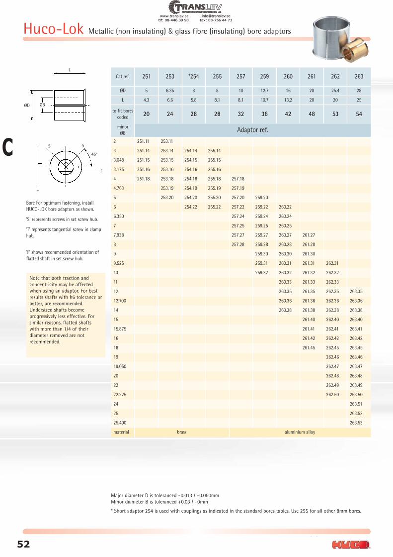
+44 (0) 1992 501900
56
Huco-Lok Metallic (non insulating) & glass fibre (insulating) bore adaptors
L
ØD ØB
SS
T
F
45°
Bore For optimum fastening, install
HUCO-LOK bore adaptors as shown.
'S' represents screws in set screw hub.
'T' represents tangential screw in clamp
hub.
'F' shows recommended orientation of
flatted shaft in set screw hub.
Major diameter D is toleranced –0.013 / –0.050mm
Minor diameter B is toleranced +0.03 / –0mm
* Short adaptor 254 is used with couplings as indicated in the standard bores tables. Use 255 for all other 8mm bores.
Note that both traction and
concentricity may be affected
when using an adaptor. For best
results shafts with h6 tolerance or
better, are recommended.
Undersized shafts become
progressively less effective. For
similar reasons, flatted shafts
with more than 1/4 of their
diameter removed are not
recommended.
Cat ref.
ØD 5 6.35 8 8 10 12.7 16 20 25.4 28
L
to fit bores
coded
minor
ØB
2 251.11 253.11
3 251.14 253.14 254.14 255.14
3.048 251.15 253.15 254.15 255.15
3.175 251.16 253.16 254.16 255.16
4 251.18 253.18 254.18 255.18 257.18
4.763 253.19 254.19 255.19 257.19
5 253.20 254.20 255.20 257.20 259.20
6 254.22 255.22 257.22 259.22 260.22
6.350 257.24 259.24 260.24
7 257.25 259.25 260.25
7.938 257.27 259.27 260.27 261.27
8 257.28 259.28 260.28 261.28
9 259.30 260.30 261.30
9.525 259.31 260.31 261.31 262.31
10 259.32 260.32 261.32 262.32
11 260.33 261.33 262.33
12 260.35 261.35 262.35 263.35
12.700 260.36 261.36 262.36 263.36
14 260.38 261.38 262.38 263.38
15 261.40 262.40 263.40
15.875 261.41 262.41 263.41
16 261.42 262.42 263.42
18 261.45 262.45 263.45
19 262.46 263.46
19.050 262.47 263.47
20 262.48 263.48
22 262.49 263.49
22.225 262.50 263.50
24 263.51
25 263.52
25.400 263.53
material brass aluminium alloy
20 24 28 28 32 36 42 48 53 54
4.3 6.6 5.8 8.1 8.1 10.7 13.2 20 20 25
251 253 *254 255 257 259 260 261 262 263
Adaptor ref.
52
C
www.translev.se [email protected]: 08-446 39 90 fax: 08-756 44 73
tlf: 08-
.twww -446 39 90
.seanslevtr fax: 08
info@ 8-756 44 73
.seanslev@tr 3

Formulae and ConversionFactors forMotion Transfer
www.translev.se [email protected]: 08-446 39 90 fax: 08-756 44 73
tlf: 08-
.twww -446 39 90
.seanslevtr fax: 08
info@ 8-756 44 73
.seanslev@tr 3

Formulae and Conversion Factors
+44 (0) 1992 501900
58
Quantity Unit Symbol Name
length m metre
mass kg kilogram
time s second
electric current A ampere
Thermodynamic temperature K kelvin
luminous intensity cd candela
SI base units
Symbol Quantity SI Unit Name
Symbol
Mechanics
E modulus of elasticity
(Young’s modulus) Pa pascal
F force N Newton
G (W) weight N Newton
J moment of inertia kgm2 kilogram
metre squared
M (T) torque Nm Newton metre
m mass kg kilogram
P power W watt
p pressure Pa pascal
ρ density (mas density) kg/m3 -
σ stress Pa pascal
W (E) work (energy) J joule
η efficiency 1 -
μ coefficient of friction 1 -
Lifting motion
P =
Linear motion
P =
Fr =
Rotary motion
P =
P - Power in kW
Fr - Frictional resistance in N
m - Mass in kg
g - Acceleration of free fall
(9.81) in m/s2
v - Velocity in m/sη - Efficiency in decimalsμ - Coefficient of friction
M - Torque in Nm
n - Rotational speed in
1/min or r/min
M . n
9550
μ . m . g
Fr . v
1000
m . g . v
η . 1000
Lifting motion
P =
Linear motion
P =
Fr =
Rotary motion
P =
P - Power in hp
Fr - Frictional resistance in lbf
W - Weight in lb
g - Acceleration of free fall
(9.81) in m/s2
v - Velocity in ft/minη - Efficiency in decimalsμ - Coefficient of friction
M - Torque in lbf . ft
n - Rotational speed in
rpm
M . n
5250
μ . W
Fr . v
33000
W . v
η . 33000
M - F . r
P =
M - Torque in Nm
F - Force in N
r - Radius of lever in m
P - Power in kW
n - Rotational speed in
1/min or r/min
9550 . P
n
M - F . r
P =
M - Torque in lbf . ft
F - Force in lbf
r - Radius of lever in ft
P - Power in hp
n - Rotational speed in
rpm
5250 . P
n
letter symbols and SI units in power transmission engineering
Formulae
power
International System(SI) Imperial System (FPS)
Solid Cylinder
J =
J =
J = 98 ρ . l . d4ext
Hollow Cylinder
J =
J =
J= 98 . ρ . l (d4
ext - d4int)
1 . 1000 . π . ρ . l (d4ext - d4
int)32
1 . m . (r2ext + r2
int)2
1 . 1000 . π . ρ . l . d4ext
32
1 . m . r2ext
2
Solid Cylinder
WK2 =
WK2 =
= 0.1 ρ . l . d4ext
Hollow Cylinder
WK2 =
WK2 =
J= 0.1 . ρ . l (d4
ext - d4int)
π . ρ . l (d4ext - d4
int)32
1 . W . (r2ext + r2
int)2
π . ρ . l . d4ext
32
1 . W . r2ext
2
moment of inertia
torque
W - F . s = m . g . s
W =
W - Work (energy) in Nm = Ws = J
F - Force in N
s - Length of path in m
m - Mass in kg
g - Acceleration of free fall
(9.81) in m/s2
J - Moment of inertia in kgm2
n - Rotational speed in
1/min or r/min
j . n2
182.5
W - F . s
W =
W - Work (energy) in lb . ft
F - Force in lbf
s - Length of path in ft
m - Mass in kg
g - Acceleration of free fall
(9.81) in m/s2
WK2-Flywheel effect lb . ft2
n - Rotational speed in
rpm
WK2 . n2
5880
work
ta =
ta - Acceleration or
braking time in s
J - Moment of inertia in kgm2
n - Rotational speed in
1/min or r/min
Ma- Acceleration or
braking torque in Nm
J . n
9.55. Ma
ta =
ta - Acceleration or
braking time in s
WK2-Flywheel effect in kgm2
n - Rotational speed in
rpm
Ma- Acceleration or
braking torque in lb . ft
WK2 . n
308. Ma
acceleration or braking time
International System(SI) Imperial System (FPS)
CT ≤ (FR x 2 π)2
1 + 1
JM + JL( )FR ≤ 1
2 π 1 + 1
JM + JL( )
torsional stiffness and resonant frequency
x x CT
WhereCT = torsional stiffness
(Nm/rad);JM = motor inertia (kgm2)FR = resonant frequency (Hz)JL = load inertia (kgm2)
54
C
www.translev.se [email protected]: 08-446 39 90 fax: 08-756 44 73
tlf: 08-
.twww -446 39 90
.seanslevtr fax: 08
info@ 8-756 44 73
.seanslev@tr 3

Formulae and Conversion Factors
59
www.huco.com
forceN kp p tonf (UK) lbf ozf
1N = 1 0.1020 102.0 100.4 x 10⁻⁶ 0.2248 3.5971kp = 9.807 1 1000 0.984 x 10⁻³ 2.205 35.271p = 9.81 x 10⁻³ 1 x 10⁻³ 1 0.984 x 10⁻⁶ 2.2 x 10⁻³ 35.3 x 10⁻³
1tonf (UK) = 9964 1016 1.02 x 10⁶ 1 2240 35.8 x 10³
1lbf = 4.448 0.4536 453.6 0.5 x 10⁻⁶ 1 161ozf
km/h m/min m/s mile/h ft/min ft/s in/s1km/h = 1 16.667 0.2778 0.6214 54.68 0.9113 10.936m/min = 0.06 1 16.7 x 10⁻³ 37.3 x 10⁻³ 3.281 54.7 x 10⁻³ 0.6561m/s = 3.6 60 1 2.237 196.85 3.281 39.37
1mile/h = 1.609 26.82 0.4470 1 88 1.467 17.61ft/min = 18.3 x 10⁻³ 0.3048 5.08 x 10⁻³ 11.4 x 10⁻³ 1 16.7 x 10⁻³ 0.2
1ft/s = 1.097 18.288 0.3048 0.6818 60 1 121in/s = 91 x 10-3 1.524 25.4 x 10⁻³ 56.8 x 10⁻³ 5 83.3 x 10⁻³ 1
= - 28.4 x 10⁻³ 28.35 27.9 x 10⁻⁶ 62.5 x 10⁻³ 1
lengthmm m in ft yds km miles
1mm 1 0.001 0.3937 0.0033 0.00109 - -1m 1000 1 39.370 3.2808 1.0936 0.001 0.00062151in 25.4 0.0254 1 0.0833 0.0277 0.0000254 0.00001581ft 304.8 0.3048 12 1 0.3333 0.000304 0.00018941yd 914.4 0.9144 36 3 1 0.000914 0.0005681km - 1000 39,370.07 3,280.83 1,093.613 1 0.62151mile - 1,609 63,346.45 5,278.87 1,759.623 1.609 1
torqueNm Ncm kgfm lbf.ft lbf.in ozf.in
1Nm = 1 100 0.10197 0.73756 8.8507 141.61Ncm = 0.01 1 1.02 x 10⁻³ 7.376 x 10⁻³ 88.5 x 10⁻³ 1.4161
1kgfm = 9.8067 980.67 1 7.233 86.796 13891lbf.ft = 1.356 135.6 0.1383 1 12 1921lbf.in = 0.1129 11.29 11.5 x 10⁻³ 83.3 x 10⁻³ 1 161ozf.in = 7.062 x 10⁻³ 0.7062 0.72 x 10⁻³ 5.21 x 10⁻³ 62.5 x 10⁻³ 1
powerkW PS hp kgfm/s ft.lbf/s
1kW = 1 1.360 1.341 102.0 737.61PS = 0.7355 1 0.9863 75 542.51hp = 0.7457 1.014 1 76.04 550
1kgfm/s = 9.81 x 10⁻³ 13.33 x 10⁻³ 13.15 x 10⁻³ 1 7.2331ft.lbf/s = 1.36 x 10⁻³ 1.84 x 10⁻³ 1.82 x 10⁻³ 0.1383 1
moment of inertia and other flywheel effectskgm2 (mr2) kgfm2 (GD2) lb.ft2(WK2) kpms2 ft lbf s2
1kgm2 (mr2) = 1 4 23.73 0.102 0.73761kgfm2 (GD2) = 0.25 1 5.933 25 x 10-3 0.18441lb.ft2(WK2) = 42.1 x 10⁻³ 0.1686 1 4.30 x 10⁻³ 31.1 x 10⁻³
1kpms2 = 9.807 39.23 232.7 1 7.2331ft lbf s2 = 1.356 5.423 32.17 0.1383 1
velocity C
55
www.translev.se [email protected]: 08-446 39 90 fax: 08-756 44 73
tlf: 08-
.twww -446 39 90
.seanslevtr fax: 08
info@ 8-756 44 73
.seanslev@tr 3

56
C
www.translev.se [email protected]: 08-446 39 90 fax: 08-756 44 73
tlf: 08-
.twww -446 39 90
.seanslevtr fax: 08
info@ 8-756 44 73
.seanslev@tr 3