flange yokes - pirate4x4 flange yokes... · identification of flange yokes that are bearing plate...
TRANSCRIPT
FLANGE YOKES
J300P-2JUNE 2001
SupersedesJ300P-2Dated January 1997
FLANG
E YOK
ES
Now Included...
Spicer Life Series® Flange Yokes!
2 Important: See Safety Information in General Information Section (J300P-GI)
J300P-2FLANGE YOKES
HOW TO USE THIS CATALOG
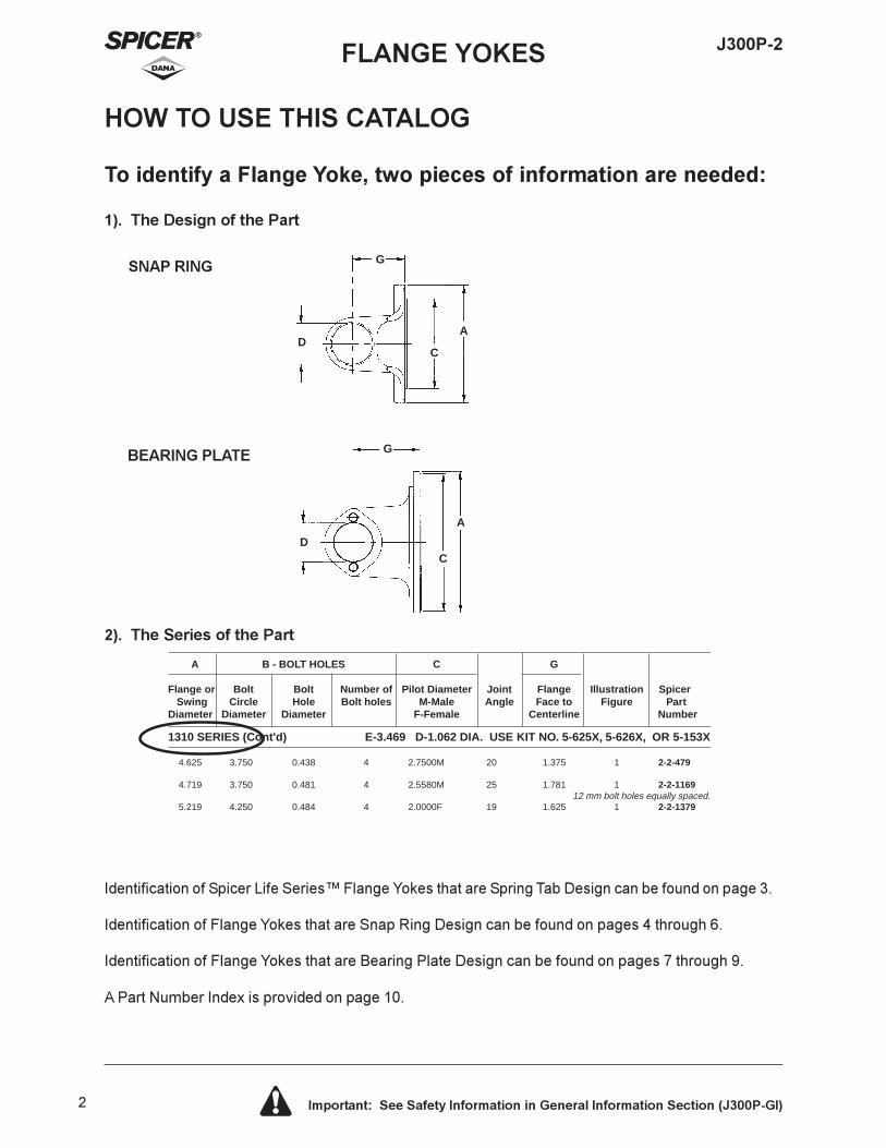
2). The Series of the Part
Identification of Spicer Life Series� Flange Yokes that are Spring Tab Design can be found on page 3.
Identification of Flange Yokes that are Snap Ring Design can be found on pages 4 through 6.
Identification of Flange Yokes that are Bearing Plate Design can be found on pages 7 through 9.
A Part Number Index is provided on page 10.
A B - BOLT HOLES C G
Flange or Bolt Bolt Number of Pilot Diameter Joint Flange Illustration Spicer Swing Circle Hole Bolt holes M-Male Angle Face to Figure PartDiameter Diameter Diameter F-Female Centerline Number
1310 SERIES (Cont'd) E-3.469 D-1.062 DIA. USE KIT NO. 5-625X, 5-626X, OR 5-153X
4.625 3.750 0.438 4 2.7500M 20 1.375 1 2-2-479
4.719 3.750 0.481 4 2.5580M 25 1.781 1 2-2-1169 12 mm bolt holes equally spaced.5.219 4.250 0.484 4 2.0000F 19 1.625 1 2-2-1379
Fig. 1
To identify a Flange Yoke, two pieces of information are needed:
1). The Design of the Part
SNAP RING
BEARING PLATE
A
C
G
D
C
AD
G
3 Important: See Safety Information in General Information Section (J300P-GI)
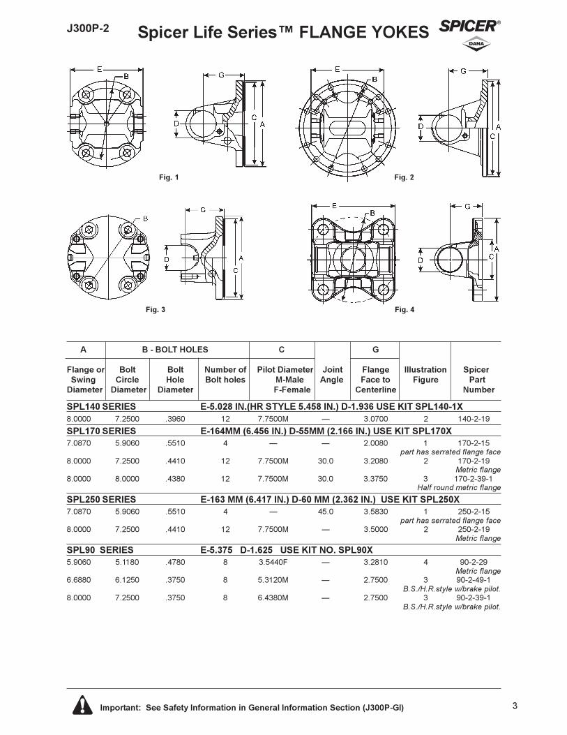
J300P-2 Spicer Life Series� FLANGE YOKES
Fig. 1 Fig. 2
A B - BOLT HOLES C G
Flange or Bolt Bolt Number of Pilot Diameter Joint Flange Illustration SpicerSwing Circle Hole Bolt holes M-Male Angle Face to Figure Part
Diameter Diameter Diameter F-Female Centerline Number
Fig. 3 Fig. 4
SPL140 SERIES E-5.028 IN.(HR STYLE 5.458 IN.) D-1.936 USE KIT SPL140-1X8.0000 7.2500 .3960 12 7.7500M � 3.0700 2 140-2-19
SPL170 SERIES E-164MM (6.456 IN.) D-55MM (2.166 IN.) USE KIT SPL170X7.0870 5.9060 .5510 4 � � 2.0080 1 170-2-15
part has serrated flange face8.0000 7.2500 .4410 12 7.7500M 30.0 3.2080 2 170-2-19
Metric flange8.0000 8.0000 .4380 12 7.7500M 30.0 3.3750 3 170-2-39-1
Half round metric flange
SPL250 SERIES E-163 MM (6.417 IN.) D-60 MM (2.362 IN.) USE KIT SPL250X7.0870 5.9060 .5510 4 � 45.0 3.5830 1 250-2-15
part has serrated flange face8.0000 7.2500 .4410 12 7.7500M � 3.5000 2 250-2-19
Metric flange
SPL90 SERIES E-5.375 D-1.625 USE KIT NO. SPL90X5.9060 5.1180 .4780 8 3.5440F � 3.2810 4 90-2-29
Metric flange6.6880 6.1250 .3750 8 5.3120M � 2.7500 3 90-2-49-1
B.S./H.R.style w/brake pilot.8.0000 7.2500 .3750 8 6.4380M � 2.7500 3 90-2-39-1
B.S./H.R.style w/brake pilot.
4 Important: See Safety Information in General Information Section (J300P-GI)
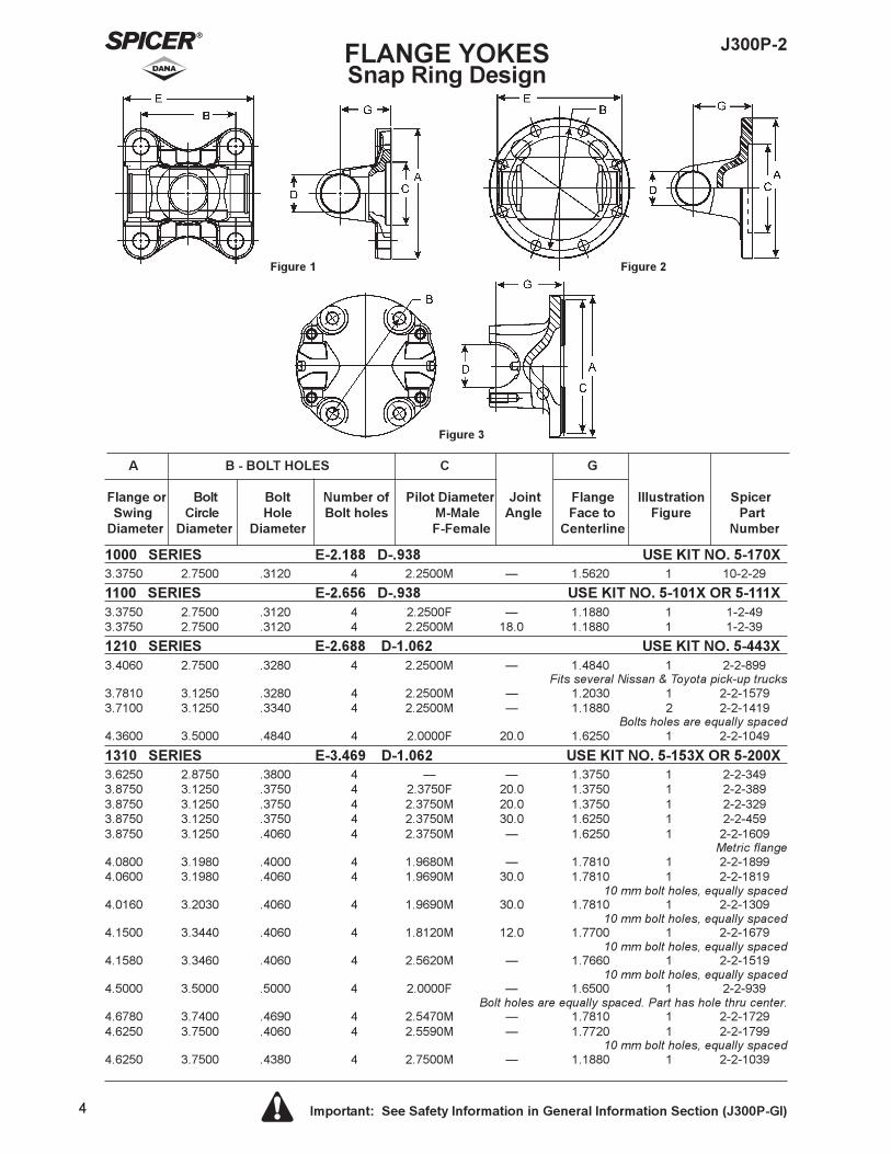
J300P-2FLANGE YOKESSnap Ring Design
A B - BOLT HOLES C G
Flange or Bolt Bolt Number of Pilot Diameter Joint Flange Illustration SpicerSwing Circle Hole Bolt holes M-Male Angle Face to Figure Part
Diameter Diameter Diameter F-Female Centerline Number
Figure 1 Figure 2
Figure 3
1000 SERIES E-2.188 D-.938 USE KIT NO. 5-170X3.3750 2.7500 .3120 4 2.2500M � 1.5620 1 10-2-29
1100 SERIES E-2.656 D-.938 USE KIT NO. 5-101X OR 5-111X3.3750 2.7500 .3120 4 2.2500F � 1.1880 1 1-2-493.3750 2.7500 .3120 4 2.2500M 18.0 1.1880 1 1-2-39
1210 SERIES E-2.688 D-1.062 USE KIT NO. 5-443X3.4060 2.7500 .3280 4 2.2500M � 1.4840 1 2-2-899
Fits several Nissan & Toyota pick-up trucks3.7810 3.1250 .3280 4 2.2500M � 1.2030 1 2-2-15793.7100 3.1250 .3340 4 2.2500M � 1.1880 2 2-2-1419
Bolts holes are equally spaced4.3600 3.5000 .4840 4 2.0000F 20.0 1.6250 1 2-2-1049
1310 SERIES E-3.469 D-1.062 USE KIT NO. 5-153X OR 5-200X3.6250 2.8750 .3800 4 � � 1.3750 1 2-2-3493.8750 3.1250 .3750 4 2.3750F 20.0 1.3750 1 2-2-3893.8750 3.1250 .3750 4 2.3750M 20.0 1.3750 1 2-2-3293.8750 3.1250 .3750 4 2.3750M 30.0 1.6250 1 2-2-4593.8750 3.1250 .4060 4 2.3750M � 1.6250 1 2-2-1609
Metric flange4.0800 3.1980 .4000 4 1.9680M � 1.7810 1 2-2-18994.0600 3.1980 .4060 4 1.9690M 30.0 1.7810 1 2-2-1819
10 mm bolt holes, equally spaced4.0160 3.2030 .4060 4 1.9690M 30.0 1.7810 1 2-2-1309
10 mm bolt holes, equally spaced4.1500 3.3440 .4060 4 1.8120M 12.0 1.7700 1 2-2-1679
10 mm bolt holes, equally spaced4.1580 3.3460 .4060 4 2.5620M � 1.7660 1 2-2-1519
10 mm bolt holes, equally spaced4.5000 3.5000 .5000 4 2.0000F � 1.6500 1 2-2-939
Bolt holes are equally spaced. Part has hole thru center.4.6780 3.7400 .4690 4 2.5470M � 1.7810 1 2-2-17294.6250 3.7500 .4060 4 2.5590M � 1.7720 1 2-2-1799
10 mm bolt holes, equally spaced4.6250 3.7500 .4380 4 2.7500M � 1.1880 1 2-2-1039
5 Important: See Safety Information in General Information Section (J300P-GI)
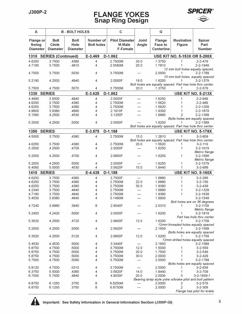
J300P-2 FLANGE YOKESSnap Ring Design
A B - BOLT HOLES C G
Flange or Bolt Bolt Number of Pilot Diameter Joint Flange Illustration SpicerSwing Circle Hole Bolt holes M-Male Angle Face to Figure Part
Diameter Diameter Diameter F-Female Centerline Number
1310 SERIES (Continued) E-3.469 D-1.062 USE KIT NO. 5-153X OR 5-200X4.6250 3.7500 .4380 4 2.7500M 20.0 1.3750 1 2-2-4794.7190 3.7500 .4810 4 2.5580M 25.0 1.7810 1 2-2-1949
12 mm bolt holes equally spaced.4.7500 3.7500 .5030 4 3.7500M � 2.0000 1 2-2-1789
10 mm bolt holes, equally spaced5.2190 4.2500 .4840 4 2.0000F 19.0 1.6250 1 2-2-1379
Bolt holes are equally spaced. Part has hole thru center.5.7500 4.7500 .5070 4 3.7500M 20.0 1.3750 1 2-2-579
1330 SERIES E-3.625 D-1.062 USE KIT NO. 5-213X4.4690 3.5000 .4840 4 2.0000F � 1.6250 1 2-2-9494.6250 3.7500 .4380 4 2.7500M � 1.5620 1 2-2-4894.6250 3.7500 .4380 4 2.7500M � 1.5620 1 2-2-12094.9600 3.9380 .4890 4 2.1610F � 1.9300 1 2-2-18795.1560 4.2500 .4530 4 3.1250F � 1.6880 2 2-2-1399
Bolts holes are equally spaced5.2500 4.2500 .5000 4 2.0000F � 1.6250 1 2-2-1369
Bolt holes are equally spaced. Part has hole thru center.
1350 SERIES E-3.875 D-1.188 USE KIT NO. 5-178X4.5000 3.7500 .4380 4 2.7500M 15.0 1.2810 1 3-2-809
Bolt holes are equally spaced. Part has hole thru center.4.6250 3.7500 .4380 4 2.7500M 20.0 1.5620 1 3-2-1195.2500 4.2500 .4700 4 2.0000F � 1.6250 1 3-2-1619
Metric flange5.2500 4.2500 .4700 4 2.6800F � 1.6250 1 3-2-1699
Metric flange5.2500 4.2500 .5000 4 2.0000F � 1.6250 1 3-2-15796.4060 5.5000 .4530 4 3.5620F 15.0 1.8440 1 3-2-699
1410 SERIES E-4.438 D-1.188 USE KIT NO. 5-160X4.6250 3.7500 .4380 4 2.7500F � 1.6880 1 3-2-2994.6250 3.7500 .4380 4 2.7500M 22.0 1.6880 1 3-2-1594.6250 3.7500 .4380 4 2.7500M 30.0 1.9380 1 3-2-4394.2340 3.7500 .4840 4 2.7500M � 1.6880 1 3-2-13294.7180 3.7500 .4840 4 2.7500M � 1.9380 1 3-2-16395.4530 3.9380 .4840 4 3.1490M � 1.6900 3-2-1549
Bolt holes are on 36 degrees4.7240 3.9960 .3940 8 2.9540F � 2.5310 1 3-2-1159
Metric flange5.2400 4.2420 .5000 4 2.0000F � 1.6200 1 3-2-1819
Part has hole thru center5.3520 4.2500 .4720 4 2.6800F 12.0 1.6200 1 3-2-1709
12mm threaded holes equally spaced5.2500 4.2500 .5000 4 2.5620F � 2.1650 1 3-2-1599
Bolts holes are equally spaced5.3520 4.2500 .5120 4 2.6800F 12.0 1.6200 1 3-2-1759
12mm drilled holes equally spaced5.4530 4.4530 .5000 4 3.3440F � 2.1650 3-2-15895.8750 4.7500 .5000 4 3.7500M 12.0 1.5000 1 3-2-5595.8750 4.7500 .5000 4 3.7500M 20.0 1.7500 1 3-2-5495.8750 4.7500 .5000 4 3.7500M 30.0 2.0000 1 3-2-4295.7500 4.7500 .5090 4 3.7500M � 2.0000 1 3-2-1789
Bolts holes are equally spaced5.8120 4.7500 .5310 4 3.7500M � 2.0000 1 3-2-9396.3750 5.5000 .4380 4 3.5620F 14.0 1.8440 1 3-2-7096.7500 5.7500 .4840 4 4.8030F 20.0 2.0000 3 3-2-1659-1
Bearing strap style yoke w/brake pilot and bolt pattern6.8750 6.1250 .3750 8 6.6250M � 2.0000 2 3-2-5796.8750 6.1250 .3750 8 6.8750M � 2.0000 2 3-2-309
Flange has pilot for brake
6 Important: See Safety Information in General Information Section (J300P-GI)
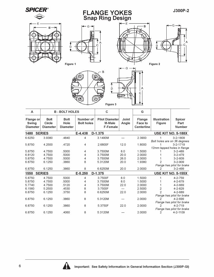
J300P-2FLANGE YOKESSnap Ring Design
A B - BOLT HOLES C G
Flange or Bolt Bolt Number of Pilot Diameter Joint Flange Illustration SpicerSwing Circle Hole Bolt holes M-Male Angle Face to Figure Part
Diameter Diameter Diameter F-Female Centerline Number
Figure 1 Figure 2
Figure 3
1480 SERIES E-4.438 D-1.375 USE KIT NO. 5-188X6.6250 3.9380 .4840 4 3.1490M � 2.3900 1 3-2-1809
Bolt holes are on 36 degrees5.8750 4.2500 .4720 4 2.6800F 12.0 1.8000 1 3-2-1719
12mm tapped holes in flange5.8750 4.7500 .5000 4 3.7500M 8.0 1.5000 1 3-2-4896.8120 4.7500 .5000 4 3.7500M 20.0 2.0000 1 3-2-4795.8750 4.7500 .5000 4 3.7500M 26.0 2.0000 1 3-2-6096.8750 6.1250 .3860 8 5.3120M 20.0 1.9380 2 3-2-909
Flange has pilot for brake6.8750 6.1250 .3860 8 6.6250M 20.0 2.0000 2 3-2-499
1550 SERIES E-5.250 D-1.375 USE KIT NO. 5-155X5.8750 4.7500 .5000 4 3.7500F 8.0 1.5000 1 4-2-7595.8750 4.7500 .5000 4 3.7500M 8.0 1.5000 1 4-2-6795.7740 4.7500 .5120 4 3.7500M 22.0 2.0000 1 4-2-6696.1560 5.2500 .4530 8 3.7500F � 2.5000 2 4-2-8296.8750 6.1250 .3750 8 6.6250M 22.0 2.0000 2 4-2-689
Flange has pilot for brake6.8750 6.1250 .3860 8 5.3120M � 2.0000 2 4-2-699
Flange has pilot for brake6.8750 6.1250 .3860 8 5.3750F 22.0 2.0000 2 4-2-719
Flange has pilot for brake6.8750 6.1250 .4060 8 5.3120M � 2.0000 2 4-2-1109
7 Important: See Safety Information in General Information Section (J300P-GI)
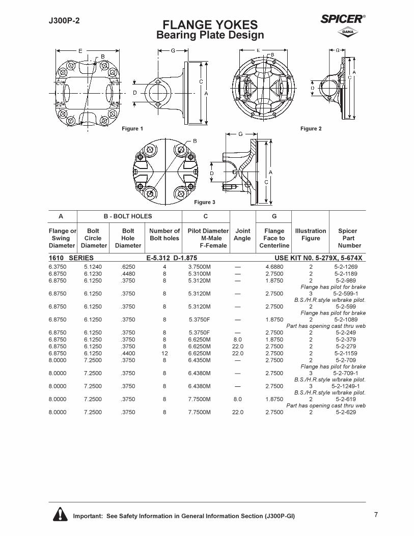
J300P-2 FLANGE YOKESBearing Plate Design
A B - BOLT HOLES C G
Flange or Bolt Bolt Number of Pilot Diameter Joint Flange Illustration SpicerSwing Circle Hole Bolt holes M-Male Angle Face to Figure Part
Diameter Diameter Diameter F-Female Centerline Number
Figure 1 Figure 2
Figure 3
1610 SERIES E-5.312 D-1.875 USE KIT N0. 5-279X, 5-674X6.3750 5.1240 .6250 4 3.7500M � 4.6880 2 5-2-12696.8750 6.1230 .4480 8 5.3100M � 2.7500 2 5-2-11896.8750 6.1250 .3750 8 5.3120M � 1.8750 2 5-2-989
Flange has pilot for brake6.8750 6.1250 .3750 8 5.3120M � 2.7500 3 5-2-599-1
B.S./H.R.style w/brake pilot.6.8750 6.1250 .3750 8 5.3120M � 2.7500 2 5-2-599
Flange has pilot for brake6.8750 6.1250 .3750 8 5.3750F � 1.8750 2 5-2-1089
Part has opening cast thru web6.8750 6.1250 .3750 8 5.3750F � 2.7500 2 5-2-2496.8750 6.1250 .3750 8 6.6250M 8.0 1.8750 2 5-2-3796.8750 6.1250 .3750 8 6.6250M 22.0 2.7500 2 5-2-2796.8750 6.1250 .4400 12 6.6250M 22.0 2.7500 2 5-2-11598.0000 7.2500 .3750 8 6.4350M � 2.7500 2 5-2-709
Flange has pilot for brake8.0000 7.2500 .3750 8 6.4380M � 2.7500 3 5-2-709-1
B.S./H.R.style w/brake pilot.8.0000 7.2500 .3750 8 6.4380M � 2.7500 3 5-2-1249-1
B.S./H.R.style w/brake pilot.8.0000 7.2500 .3750 8 7.7500M 8.0 1.8750 2 5-2-619
Part has opening cast thru web8.0000 7.2500 .3750 8 7.7500M 22.0 2.7500 2 5-2-629
8 Important: See Safety Information in General Information Section (J300P-GI)
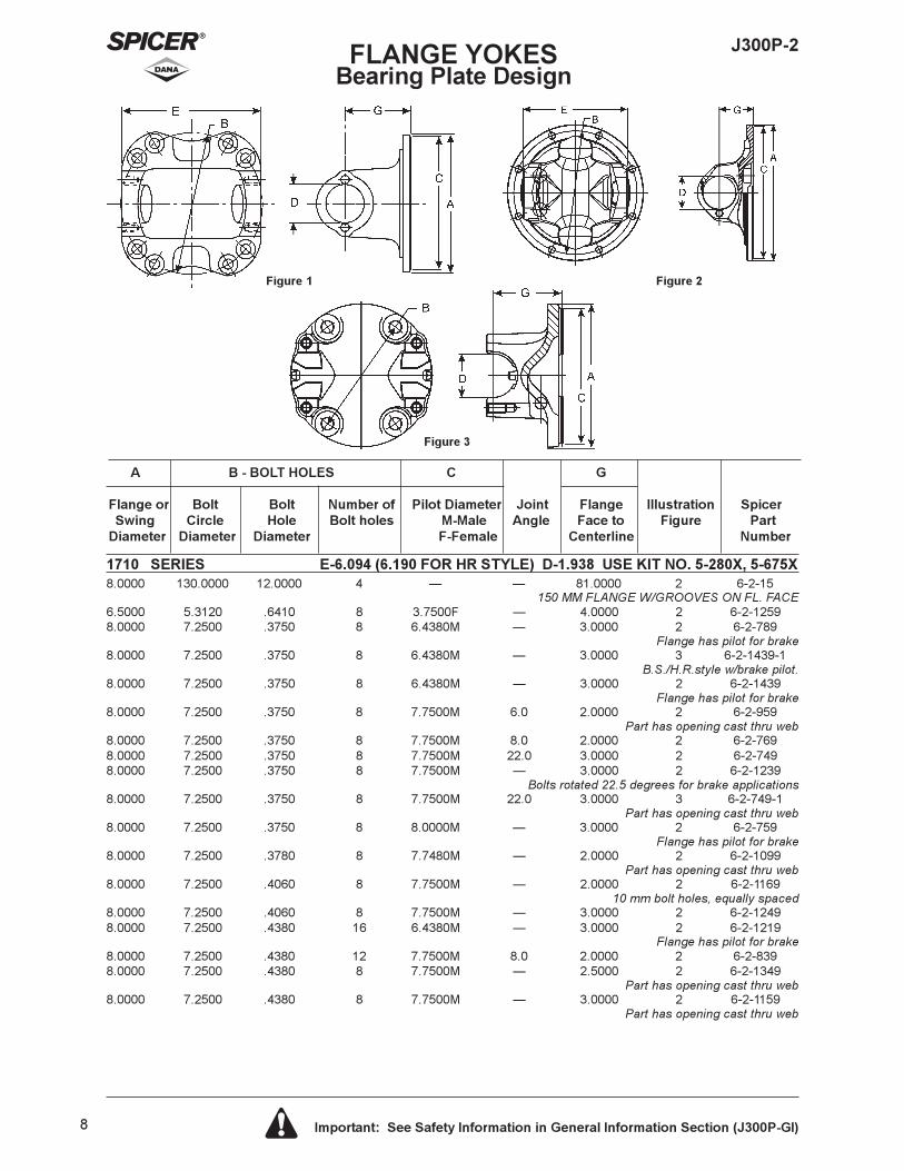
J300P-2FLANGE YOKESBearing Plate Design
A B - BOLT HOLES C G
Flange or Bolt Bolt Number of Pilot Diameter Joint Flange Illustration SpicerSwing Circle Hole Bolt holes M-Male Angle Face to Figure Part
Diameter Diameter Diameter F-Female Centerline Number
Figure 1 Figure 2
Figure 3
1710 SERIES E-6.094 (6.190 FOR HR STYLE) D-1.938 USE KIT NO. 5-280X, 5-675X8.0000 130.0000 12.0000 4 � � 81.0000 2 6-2-15
150 MM FLANGE W/GROOVES ON FL. FACE6.5000 5.3120 .6410 8 3.7500F � 4.0000 2 6-2-12598.0000 7.2500 .3750 8 6.4380M � 3.0000 2 6-2-789
Flange has pilot for brake8.0000 7.2500 .3750 8 6.4380M � 3.0000 3 6-2-1439-1
B.S./H.R.style w/brake pilot.8.0000 7.2500 .3750 8 6.4380M � 3.0000 2 6-2-1439
Flange has pilot for brake8.0000 7.2500 .3750 8 7.7500M 6.0 2.0000 2 6-2-959
Part has opening cast thru web8.0000 7.2500 .3750 8 7.7500M 8.0 2.0000 2 6-2-7698.0000 7.2500 .3750 8 7.7500M 22.0 3.0000 2 6-2-7498.0000 7.2500 .3750 8 7.7500M � 3.0000 2 6-2-1239
Bolts rotated 22.5 degrees for brake applications8.0000 7.2500 .3750 8 7.7500M 22.0 3.0000 3 6-2-749-1
Part has opening cast thru web8.0000 7.2500 .3750 8 8.0000M � 3.0000 2 6-2-759
Flange has pilot for brake8.0000 7.2500 .3780 8 7.7480M � 2.0000 2 6-2-1099
Part has opening cast thru web8.0000 7.2500 .4060 8 7.7500M � 2.0000 2 6-2-1169
10 mm bolt holes, equally spaced8.0000 7.2500 .4060 8 7.7500M � 3.0000 2 6-2-12498.0000 7.2500 .4380 16 6.4380M � 3.0000 2 6-2-1219
Flange has pilot for brake8.0000 7.2500 .4380 12 7.7500M 8.0 2.0000 2 6-2-8398.0000 7.2500 .4380 8 7.7500M � 2.5000 2 6-2-1349
Part has opening cast thru web8.0000 7.2500 .4380 8 7.7500M � 3.0000 2 6-2-1159
Part has opening cast thru web
J300P-2 FLANGE YOKESBearing Plate Design
A B - BOLT HOLES C G
Flange or Bolt Bolt Number of Pilot Diameter Joint Flange Illustration SpicerSwing Circle Hole Bolt holes M-Male Angle Face to Figure Part
Diameter Diameter Diameter F-Female Centerline Number
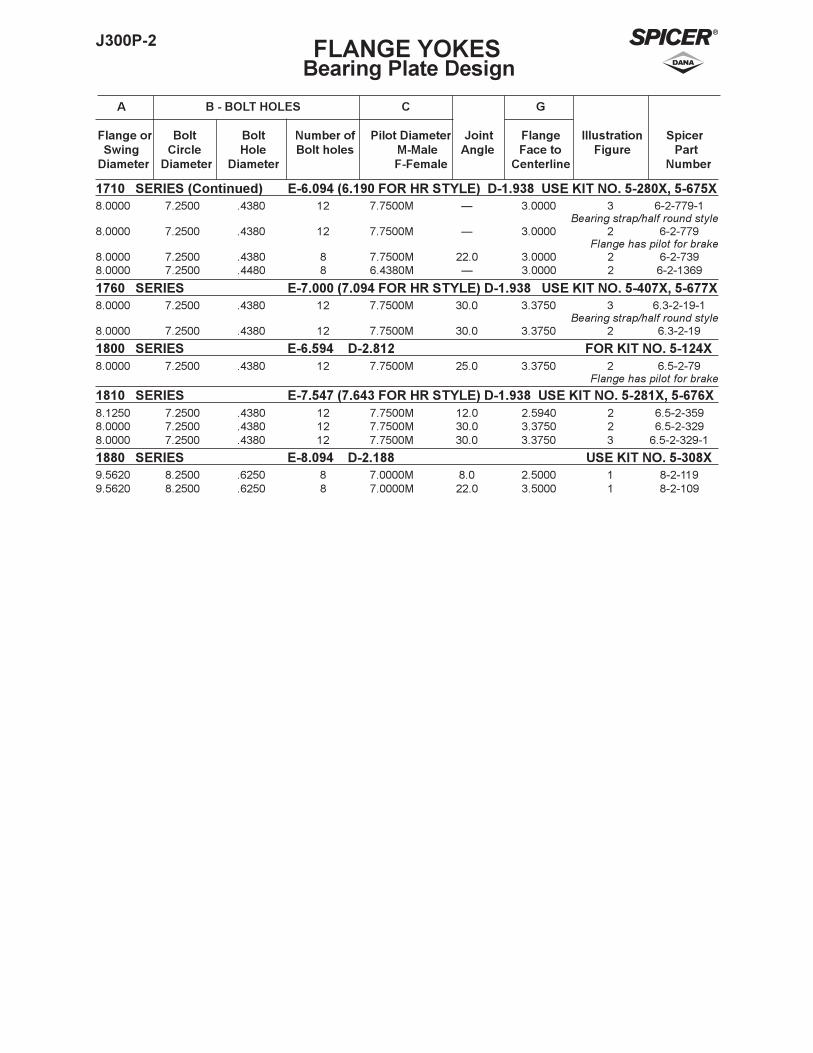
1710 SERIES (Continued) E-6.094 (6.190 FOR HR STYLE) D-1.938 USE KIT NO. 5-280X, 5-675X8.0000 7.2500 .4380 12 7.7500M � 3.0000 3 6-2-779-1
Bearing strap/half round style8.0000 7.2500 .4380 12 7.7500M � 3.0000 2 6-2-779
Flange has pilot for brake8.0000 7.2500 .4380 8 7.7500M 22.0 3.0000 2 6-2-7398.0000 7.2500 .4480 8 6.4380M � 3.0000 2 6-2-1369
1760 SERIES E-7.000 (7.094 FOR HR STYLE) D-1.938 USE KIT NO. 5-407X, 5-677X8.0000 7.2500 .4380 12 7.7500M 30.0 3.3750 3 6.3-2-19-1
Bearing strap/half round style8.0000 7.2500 .4380 12 7.7500M 30.0 3.3750 2 6.3-2-19
1800 SERIES E-6.594 D-2.812 FOR KIT NO. 5-124X8.0000 7.2500 .4380 12 7.7500M 25.0 3.3750 2 6.5-2-79
Flange has pilot for brake
1810 SERIES E-7.547 (7.643 FOR HR STYLE) D-1.938 USE KIT NO. 5-281X, 5-676X8.1250 7.2500 .4380 12 7.7500M 12.0 2.5940 2 6.5-2-3598.0000 7.2500 .4380 12 7.7500M 30.0 3.3750 2 6.5-2-3298.0000 7.2500 .4380 12 7.7500M 30.0 3.3750 3 6.5-2-329-1
1880 SERIES E-8.094 D-2.188 USE KIT NO. 5-308X9.5620 8.2500 .6250 8 7.0000M 8.0 2.5000 1 8-2-1199.5620 8.2500 .6250 8 7.0000M 22.0 3.5000 1 8-2-109
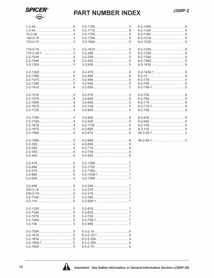
1-2-39 .......................................... 41-2-49 .......................................... 410-2-29 ........................................ 4140-2-19 ...................................... 3170-2-15 ...................................... 3
170-2-19 ...................................... 3170-2-39-1 .................................. 32-2-1039 ...................................... 42-2-1049 ...................................... 42-2-1209 ...................................... 5
2-2-1309 ...................................... 42-2-1369 ...................................... 52-2-1379 ...................................... 52-2-1399 ...................................... 52-2-1419 ...................................... 4
2-2-1519 ...................................... 42-2-1579 ...................................... 42-2-1609 ...................................... 42-2-1679 ...................................... 42-2-1729 ...................................... 4
2-2-1789 ...................................... 52-2-1799 ...................................... 42-2-1819 ...................................... 42-2-1879 ...................................... 52-2-1899 ...................................... 4
2-2-1949 ...................................... 52-2-329 ........................................ 42-2-349 ........................................ 42-2-389 ........................................ 42-2-459 ........................................ 4
2-2-479 ........................................ 52-2-489 ........................................ 52-2-579 ........................................ 52-2-899 ........................................ 42-2-939 ........................................ 4
2-2-949 ........................................ 5250-2-15 ...................................... 3250-2-19 ...................................... 33-2-1159 ...................................... 53-2-119 ........................................ 5
3-2-1329 ...................................... 53-2-1549 ...................................... 53-2-1579 ...................................... 53-2-1589 ...................................... 53-2-159 ........................................ 5
3-2-1599 ...................................... 53-2-1619 ...................................... 53-2-1639 ...................................... 53-2-1659-1 .................................. 53-2-1699 ...................................... 5
3-2-1709 ...................................... 53-2-1719 ...................................... 63-2-1759 ...................................... 53-2-1789 ...................................... 53-2-1809 ...................................... 6
3-2-1819 ...................................... 53-2-299 ........................................ 53-2-309 ........................................ 53-2-429 ........................................ 53-2-439 ........................................ 5
3-2-479 ........................................ 63-2-489 ........................................ 63-2-499 ........................................ 63-2-549 ........................................ 53-2-559 ........................................ 5
3-2-579 ........................................ 53-2-609 ........................................ 63-2-699 ........................................ 53-2-709 ........................................ 53-2-809 ........................................ 5
3-2-909 ........................................ 63-2-939 ........................................ 54-2-1109 ...................................... 64-2-669 ........................................ 64-2-679 ........................................ 6
4-2-689 ........................................ 64-2-699 ........................................ 64-2-719 ........................................ 64-2-759 ........................................ 64-2-829 ........................................ 6
5-2-1089 ...................................... 75-2-1159 ...................................... 75-2-1189 ...................................... 75-2-1249-1 .................................. 75-2-1269 ...................................... 7
5-2-249 ........................................ 75-2-279 ........................................ 75-2-379 ........................................ 75-2-599 ........................................ 75-2-599-1 .................................... 7
5-2-619 ........................................ 75-2-629 ........................................ 75-2-709 ........................................ 75-2-709-1 .................................... 75-2-989 ........................................ 7
6.3-2-19 ....................................... 96.3-2-19-1 ................................... 96.5-2-329 ..................................... 96.5-2-359 ..................................... 96.5-2-79 ....................................... 9
6-2-1099 ...................................... 86-2-1159 ...................................... 86-2-1169 ...................................... 86-2-1219 ...................................... 86-2-1239 ...................................... 8
6-2-1249 ...................................... 86-2-1259 ...................................... 86-2-1349 ...................................... 86-2-1369 ...................................... 96-2-1439 ...................................... 8
6-2-1439-1 .................................. 86-2-15 .......................................... 86-2-739 ........................................ 96-2-749 ........................................ 86-2-749-1 .................................... 8
6-2-759 ........................................ 86-2-769 ........................................ 86-2-779 ........................................ 96-2-779-1 .................................... 96-2-789 ........................................ 8
6-2-839 ........................................ 86-2-959 ........................................ 88-2-109 ........................................ 98-2-119 ........................................ 990-2-39-1 .................................... 3
90-2-49-1 .................................... 3
10 Important: See Safety Information in General Information Section (J300P-GI)
J300P-2PART NUMBER INDEX
10 Important: See Safety Information in General Information Section (J300P-GI)
J300P-2 NOTES

Commercial Vehicle Service PartsDana CorporationP.O. Box 321Toledo, OH 43697Phone: 419-866-3900Fax: 419-866-3925www.dana.comwww2.dana.com/expert
© Dana Corporation, 2001