fisher 1061 pneumatic piston rotary actuator with style f ... · pdf filefisher™ 1061...
TRANSCRIPT
www.Fisher.com
Fisher™ 1061 Pneumatic Piston Rotary Actuatorwith Style F & G Mounting Adaptations
ContentsIntroduction 1. . . . . . . . . . . . . . . . . . . . . . . . . . . . . . . . .
Scope of Manual 1. . . . . . . . . . . . . . . . . . . . . . . . . . . . .Description 2. . . . . . . . . . . . . . . . . . . . . . . . . . . . . . . . .Specifications 2. . . . . . . . . . . . . . . . . . . . . . . . . . . . . . .Educational Services 3. . . . . . . . . . . . . . . . . . . . . . . . .
Principle of Operation 3. . . . . . . . . . . . . . . . . . . . . . . . .Installation 3. . . . . . . . . . . . . . . . . . . . . . . . . . . . . . . . . .
Actuator Mounting 3. . . . . . . . . . . . . . . . . . . . . . . . . .Changing Actuator Mounting 8. . . . . . . . . . . . . . . . . .Pressure Connections 9. . . . . . . . . . . . . . . . . . . . . . . .
Adjustment 9. . . . . . . . . . . . . . . . . . . . . . . . . . . . . . . . . .Maintenance 10. . . . . . . . . . . . . . . . . . . . . . . . . . . . . . . .
Disassembly 11. . . . . . . . . . . . . . . . . . . . . . . . . . . . . . .Assembly 12. . . . . . . . . . . . . . . . . . . . . . . . . . . . . . . . . .
Locking Mechanism 14. . . . . . . . . . . . . . . . . . . . . . . . . .Installing the Locking Mechanism 15. . . . . . . . . . . . .Operating the Locking Mechanism 16. . . . . . . . . . . .
Pipe‐Away Vent 18. . . . . . . . . . . . . . . . . . . . . . . . . . . . . .Parts Ordering 19. . . . . . . . . . . . . . . . . . . . . . . . . . . . . . .Parts Kits 19. . . . . . . . . . . . . . . . . . . . . . . . . . . . . . . . . . .
Actuator Repair Kits 19. . . . . . . . . . . . . . . . . . . . . . . . .Pipe‐Away Vent Retrofit Kits 19. . . . . . . . . . . . . . . . . .
Parts List 19. . . . . . . . . . . . . . . . . . . . . . . . . . . . . . . . . . .Actuator Common Parts 19. . . . . . . . . . . . . . . . . . . . .
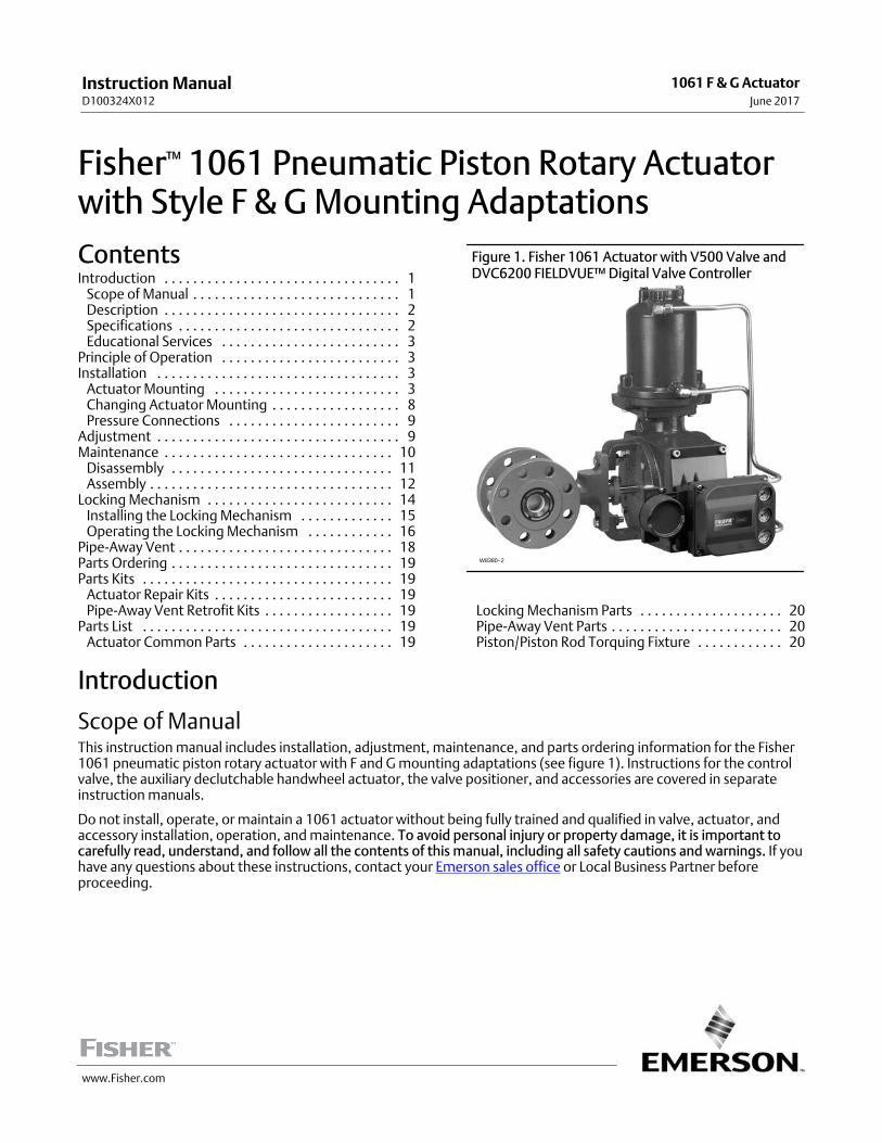
Figure 1. Fisher 1061 Actuator with V500 Valve andDVC6200 FIELDVUE™ Digital Valve Controller
W8380−2
Locking Mechanism Parts 20. . . . . . . . . . . . . . . . . . . .Pipe‐Away Vent Parts 20. . . . . . . . . . . . . . . . . . . . . . . .Piston/Piston Rod Torquing Fixture 20. . . . . . . . . . . .
Introduction
Scope of ManualThis instruction manual includes installation, adjustment, maintenance, and parts ordering information for the Fisher1061 pneumatic piston rotary actuator with F and G mounting adaptations (see figure 1). Instructions for the controlvalve, the auxiliary declutchable handwheel actuator, the valve positioner, and accessories are covered in separateinstruction manuals.
Do not install, operate, or maintain a 1061 actuator without being fully trained and qualified in valve, actuator, andaccessory installation, operation, and maintenance. To avoid personal injury or property damage, it is important tocarefully read, understand, and follow all the contents of this manual, including all safety cautions and warnings. If youhave any questions about these instructions, contact your Emerson sales office or Local Business Partner beforeproceeding.
Instruction ManualD100324X012
1061 F & G ActuatorJune 2017
Instruction ManualD100324X012
1061 F & G ActuatorJune 2017
2
Table 1. Specifications
Available Configuration
Double‐acting pneumatic piston rotary actuator for� � throttling service when used with positioner, or� � on‐off service when used with switching devices
Actuator Sizes
� � 30, � � 40, � � 60, � � 68, � � 80, � � 100, � �and � � 130,
Cylinder Operating Pressure
Minimum Recommended:
� � 1.4 bar (20 psig) without positioner or� � 0.3 bar (5 psig) above actuator requirement withpositioner
Maximum Allowable(1):
Size 30 and 60: 6.9 bar (100 psig)Size 40: 10.3 bar (150 psig)Size 68: 5.9 bar (85 psig)Size 80: 10.3 bar (150 psig)Size 100: 10.3 bar (150 psig)Size 130: 10.3 bar (150 psig)
Valve Shaft Diameters, mm (Inches)
Size 30: � � 12.7 (1/2), � � 15.9 (5/8), � � 19.1 (3/4), � � 22.2 (7/8), � � 25.4 (1), and � � 31.8 (1‐1/4)
Size 40, 60, and 68: � � 19.1 (3/4), � � 22.2 (7/8), � � 25.4 (1), � � 31.8 (1‐1/4), � � 38.1 (1/2), � � 44.5(1‐3/4), and � � 50.8 (2)
Size 80 and 100: � � 44.5 (1‐3/4), � � 50.8 (2), and� � 63.5 (2‐1/2)
Size 130: � � 76.2 (3), � � 88.9 (3‐1/2)
Maximum Valve Shaft Rotation
� � 90 degrees or � � 60 degrees (travel stop requiredfor 60 degree rotation limit)
Material Temperature Capabilities with StandardElastomers(1)
-34 to 82�C (-30 to 180�F)
Pressure Connections
� 1/4 NPT internal (standard)� 1/2 and 3/4 NPT internal (optional on sizes 68, 80,and 100)� 3/4 NPT internal for Pipe-Away Vent option� 1 NPT internal for size 130
Travel Indication
Graduated scale and pointer located on actuatorcover at actuator end of valve shaft
Mounting Positions
See figure 2
Approximate Weights
Size 30: 22 kg (49 lb)Size 40: 29 kg (63 lb)Size 60: 39 kg (86 lb)Size 68: 56 kg (123 lb)Size 80: 122 kg (246 lb)Size 100: 135 kg (298 lb)Size 130: 299 kg (660 lb)
1. The pressure/temperature limits in this manual and any applicable standard or code limitation for valves should not be exceeded.
DescriptionThe 1061 actuator is a double‐acting pneumatic piston rotary actuator for use with rotary‐shaft valves having splinedvalve shafts. The 1061 actuator can be used for either throttling or on‐off applications.
The style G mounting bracket is for Fisher 9500 valves only. The style F mounting bracket is for all other rotary valves.
SpecificationsSpecifications are shown in table 1 for 1061 actuators. Specifications are stamped on the nameplate. Refer to theactuator nameplate for the construction setting and serial number for the actuator when it originally came from thefactory.
Instruction ManualD100324X012
1061 F & G ActuatorJune 2017
3
Educational ServicesFor information on available courses for 1061 Style F and G actuators, as well as a variety of other products, contact:
Emerson Automation SolutionsEducational Services - RegistrationPhone: 1-641-754-3771 or 1-800-338-8158E-mail: [email protected]/fishervalvetraining
Principle of OperationPiston movement is accomplished by loading air pressure on one side of the piston, and unloading air pressure fromthe other side of the piston. If no positioner is used with the control valve, a loading device, such as a 4‐way switchingvalve, must be provided. Such a device is not furnished with the actuator.
Refer to the separate valve positioner instruction manual for the 1061 actuator principle of operation with positioner.
InstallationWhen an actuator and valve are shipped together, the actuator is normally mounted on the valve. Follow the valveinstructions when installing the control valve in the pipeline. If the actuator is shipped separately or if it is necessary tomount the actuator on the valve, perform the procedures presented in the Actuator Mounting section.
WARNING
To avoid personal injury, always wear protective gloves, clothing, and eyewear when performing any installationoperations.
To avoid personal injury or property damage caused by bursting of pressure retaining parts, be certain the serviceconditions do not exceed the limits given in table 1 or on the nameplate. Use pressure limiting or pressure relieving devicesto prevent the cylinder pressure from exceeding the maximum allowable cylinder operating pressure.
Check with your process or safety engineer for any additional measures that must be taken to protect against processmedia.
If installing into an existing application, also refer to the WARNING at the beginning of the Maintenance section in thisinstruction manual.
Actuator MountingUse the following steps to connect a valve and actuator that have been ordered separately, or if the valve or actuatorwere separated for maintenance purposes.
Key numbers used in this procedure are shown in figures 8, 9 and 11.
WARNING
Perform the steps in the WARNING at the beginning of the Maintenance section.
Instruction ManualD100324X012
1061 F & G ActuatorJune 2017
4
1. Refer to instructions in the appropriate valve instruction manual.
2. If a valve positioner is installed on the actuator, remove the positioner.
On the travel indicator side of the actuator:
3. Remove the cap screws and washers (keys 35 and 76), and remove the actuator cover (key 34). If an optionalmanual handwheel actuator is being used, it will be removed with the cover.
4. If the lever (key 28) is attached to the rod end bearing (key 12), remove the cap screw and hex nut:
� For size 30, 40, 60, and 68 actuators, remove the cap screw and hex nut (keys 13 and 14).
� For size 80 and 100 actuators, remove the cap screw, washer, and hex nut (keys 13, 84, and 85).
� For size 130 actuators, remove the cap screw and locknut (keys 13 and 85).
On the valve side of the actuator:
5. The actuator is normally positioned vertically with the valve in a horizontal pipeline. Refer to figure 2 for availablemounting styles and positions that match your application. Also, refer to the lever/shaft orientation provided in thevalve instruction manual.
CAUTION
It is important, when installing the actuator on the valve, to be sure that the valve is positioned correctly.
� Note the actuator style, position, and lever in relationship to the valve body and drive shaft end marks (see step 13,below).
� The valve internal components can be damaged if forced past its fully open or fully closed position.
6. Screw the mounting yoke (key 23) onto the actuator, and tighten the screws (key 24). Slide the actuator onto thevalve shaft, and secure the mounting yoke to the valve body with the valve mounting screws.
7. Tighten the valve mounting cap screws to the bolting torque values given in table 2.
8. Hold the valve in the correct position, and secure it with the cap screws (key 24).
Instruction ManualD100324X012
1061 F & G ActuatorJune 2017
5
MOUNTING ACTION(1)
VALVE SERIES OR DESIGN VALVE SERIES OR DESIGN
BALL/PLUGROTATION TO
CLOSEV250 V150, V200 & V300
CV500V500
DISK/BALLROTATION TO
CLOSEV250
8510B, 8532,8560
& 9500
Right‐HandPDTCPDTO
CCWCCW
AB
AB
AB
CWCW
NANA
BA
Left‐HandPDTCPDTO
CCWCCW
NANA
DC
DC
CWCW
CD
CD
Left‐Hand(Optional)(2)
PDTCPDTO
CWCW
NANA
CD
NANA
NANA
NANA
NANA
1. PDTC—Push‐down‐to‐close, and PDTO—Push‐down‐to‐open.2. A left hand ball will be required for the NPS 3 through 12 Series B and the NPS 14 to 20, with or without attenuator.
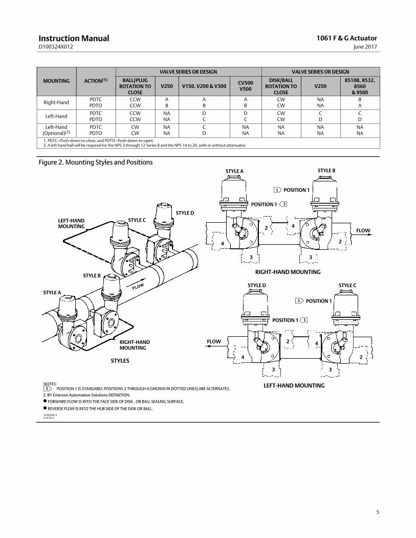
Figure 2. Mounting Styles and Positions
2. BY Emerson Automation Solutions DEFINITION:
� FORWARD FLOW IS INTO THE FACE SIDE OF DISK , OR BALL SEALING SURFACE.
� REVERSE FLOW IS INTO THE HUB SIDE OF THE DISK OR BALL.
NOTES: POSITION 1 IS STANDARD; POSITIONS 2 THROUGH 4 (SHOWN IN DOTTED LINES) ARE ALTERNATES.
LEFT‐HANDMOUNTING
STYLE C
STYLE D
STYLE B
STYLE A
RIGHT‐HANDMOUNTING
STYLE A STYLE B
STYLE D STYLE C
POSITION 1
POSITION 1
FLOW
POSITION 1
POSITION 1
FLOW
4
3
2 4
3
33
4
4
2
2
2
STYLES
RIGHT‐HAND MOUNTING
LEFT‐HAND MOUNTING
1
1
1
1
1
43A6506‐AA1579‐5
Instruction ManualD100324X012
1061 F & G ActuatorJune 2017
6
Table 2. Bolting Torque Values for Valve Mounting Cap ScrewsVALVE SHAFT DIAMETER VALVE MOUNTING CAP SCREWS
mm Inch N�m lbf‐ft
12.7 to 25.4 1/2 to 1 80 65
31.8 & 38.1 1‐1/4 & 1‐1/2 135 100
44.5 & 50.8 1‐3/4 & 2 183 135
63.5 2‐1/2 390 290
76.2 & 88.9 3 & 3‐1/2 745 550
On the travel indicator side of the actuator:
9. Screw the left‐hand threaded hex nut (key 71) onto the piston rod (key 10) as far as possible.
10. Screw the turnbuckle (key 70) onto the piston rod as far as possible. Only finger‐tighten it, as this adjustment willbe changed in a later step.
11. Screw the hex nut (key 11) onto the rod end bearing. Then thread this assembly completely into the turnbuckle.
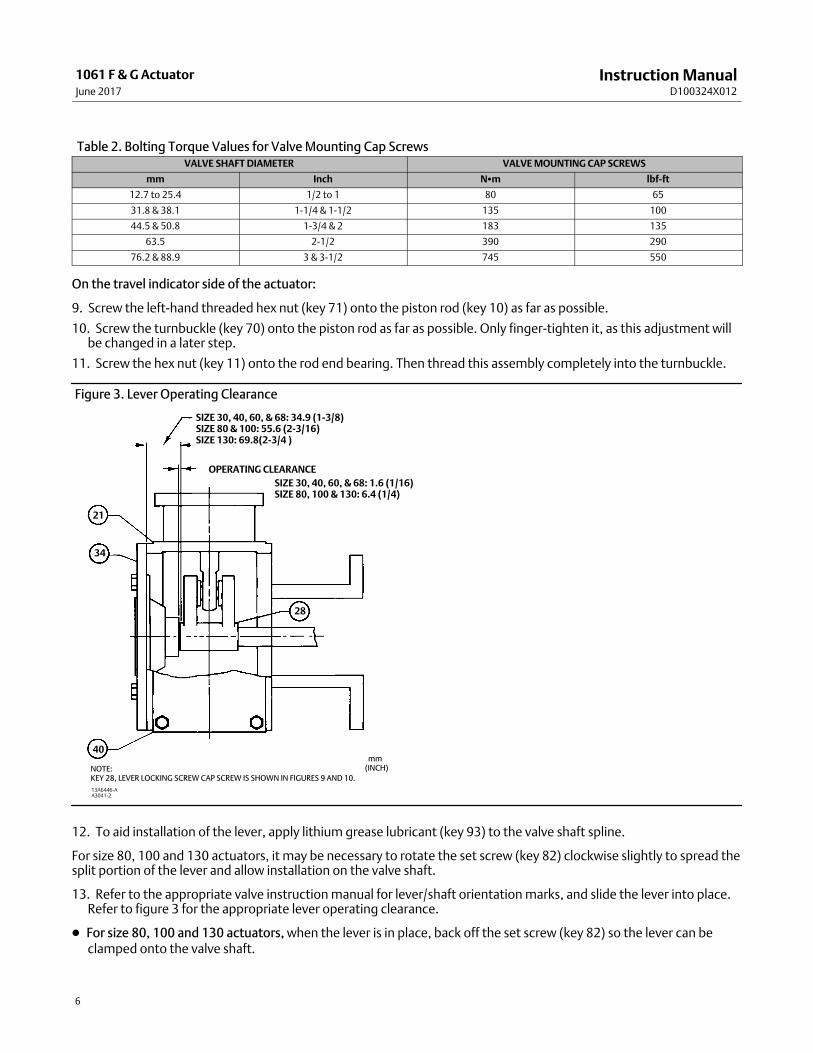
Figure 3. Lever Operating Clearance
NOTE:KEY 28, LEVER LOCKING SCREW CAP SCREW IS SHOWN IN FIGURES 9 AND 10.
SIZE 30, 40, 60, & 68: 34.9 (1‐3/8)SIZE 80 & 100: 55.6 (2‐3/16)SIZE 130: 69.8(2‐3/4 )
OPERATING CLEARANCE
SIZE 30, 40, 60, & 68: 1.6 (1/16)SIZE 80, 100 & 130: 6.4 (1/4)
mm(INCH)
13A6446‐AA3041‐2
21
34
28
40
12. To aid installation of the lever, apply lithium grease lubricant (key 93) to the valve shaft spline.
For size 80, 100 and 130 actuators, it may be necessary to rotate the set screw (key 82) clockwise slightly to spread thesplit portion of the lever and allow installation on the valve shaft.
13. Refer to the appropriate valve instruction manual for lever/shaft orientation marks, and slide the lever into place.Refer to figure 3 for the appropriate lever operating clearance.
� For size 80, 100 and 130 actuators, when the lever is in place, back off the set screw (key 82) so the lever can beclamped onto the valve shaft.
Instruction ManualD100324X012
1061 F & G ActuatorJune 2017
7
� For all sizes: Hold the lever in position, and secure the assembly with the cap screw (key 29).
14. Rotate the lever until the cap screw hole is aligned with the rod end bearing (key 12). You may need to adjust theturnbuckle to make this alignment.
15. For all actuator sizes, apply thread locking sealant (high strength) (key 83) to the cap screw (key 13) threads.
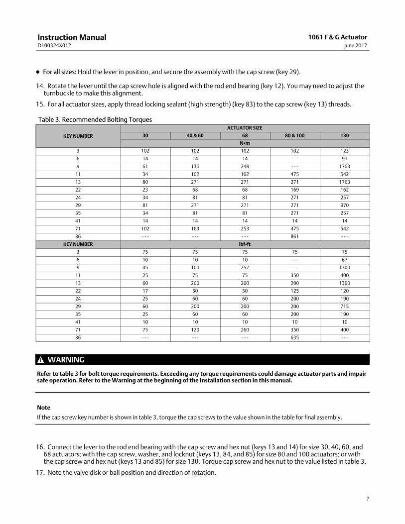
Table 3. Recommended Bolting Torques
KEY NUMBER
ACTUATOR SIZE
30 40 & 60 68 80 & 100 130
N�m
3 102 102 102 102 123
6 14 14 14 ‐ ‐ ‐ 91
9 61 136 248 ‐ ‐ ‐ 1763
11 34 102 102 475 542
13 80 271 271 271 1763
22 23 68 68 169 162
24 34 81 81 271 257
29 81 271 271 271 970
35 34 81 81 271 257
41 14 14 14 14 14
71 102 163 253 475 542
86 ‐ ‐ ‐ ‐ ‐ ‐ ‐ ‐ ‐ 861 ‐ ‐ ‐
KEY NUMBER lbf�ft
3 75 75 75 75 75
6 10 10 10 ‐ ‐ ‐ 67
9 45 100 257 ‐ ‐ ‐ 1300
11 25 75 75 350 400
13 60 200 200 200 1300
22 17 50 50 125 120
24 25 60 60 200 190
29 60 200 200 200 715
35 25 60 60 200 190
41 10 10 10 10 10
71 75 120 260 350 400
86 ‐ ‐ ‐ ‐ ‐ ‐ ‐ ‐ ‐ 635 ‐ ‐ ‐
WARNING
Refer to table 3 for bolt torque requirements. Exceeding any torque requirements could damage actuator parts and impairsafe operation. Refer to the Warning at the beginning of the Installation section in this manual.
Note
If the cap screw key number is shown in table 3, torque the cap screws to the value shown in the table for final assembly.
16. Connect the lever to the rod end bearing with the cap screw and hex nut (keys 13 and 14) for size 30, 40, 60, and68 actuators; with the cap screw, washer, and locknut (keys 13, 84, and 85) for size 80 and 100 actuators; or withthe cap screw and hex nut (keys 13 and 85) for size 130. Torque cap screw and hex nut to the value listed in table 3.
17. Note the valve disk or ball position and direction of rotation.
Instruction ManualD100324X012
1061 F & G ActuatorJune 2017
8
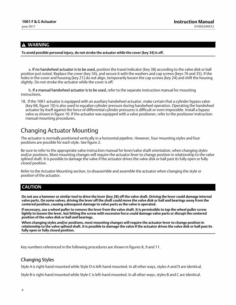
WARNING
To avoid possible personal injury, do not stroke the actuator while the cover (key 34) is off.
��a. If no handwheel actuator is to be used, position the travel indicator (key 38) according to the valve disk or ballposition just noted. Replace the cover (key 34), and secure it with the washers and cap screws (keys 76 and 35). If theholes in the cover and housing (key 21) do not align, temporarily loosen the cap screws (key 24) and shift the housingslightly. Do not stroke the actuator while the cover is off.
��b. If a manual handwheel actuator is to be used, refer to the separate instruction manual for mountinginstructions.
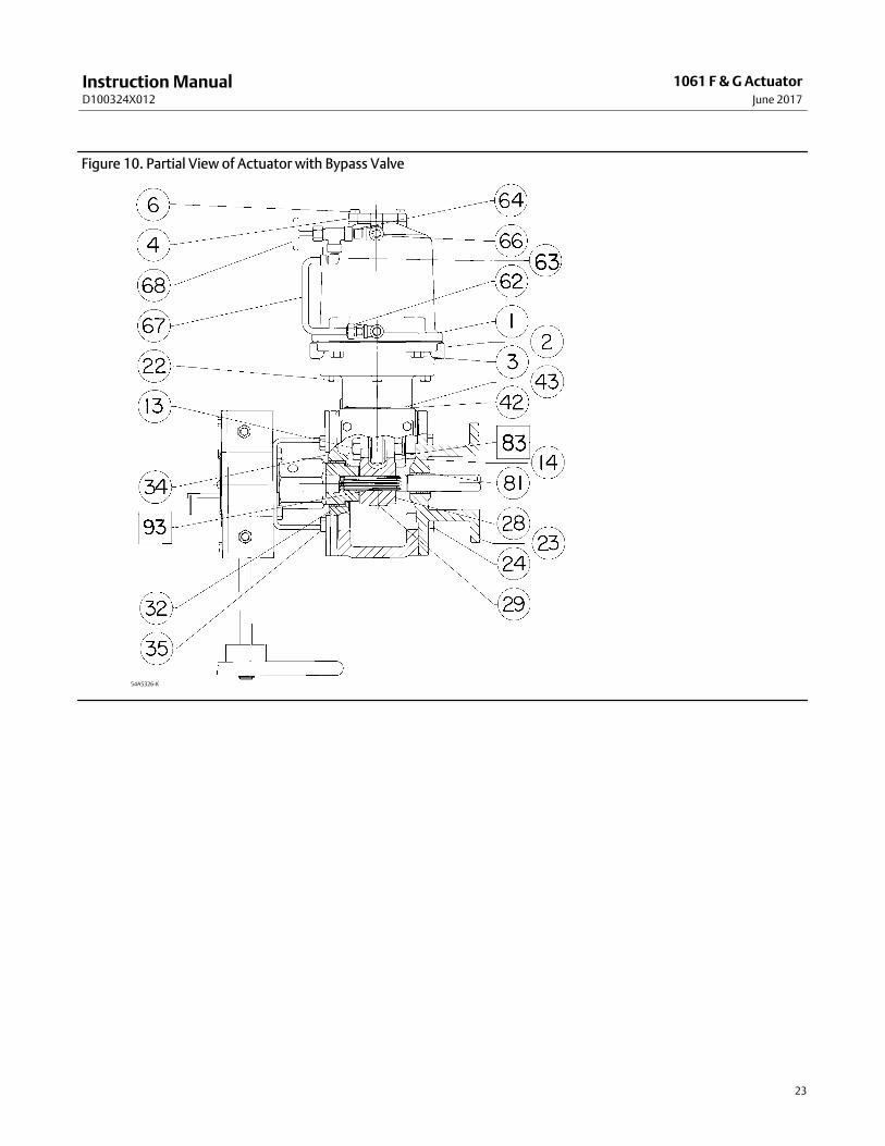
18. If the 1061 actuator is equipped with an auxiliary handwheel actuator, make certain that a cylinder bypass valve(key 68, figure 10) is also used to equalize cylinder pressure during handwheel operation. Operating the handwheelactuator by itself against the force of differential cylinder pressures is difficult or even impossible. Install a bypassvalve as shown in figure 10. If the actuator was equipped with a valve positioner, refer to the positioner instructionmanual mounting procedures.
Changing Actuator MountingThe actuator is normally positioned vertically in a horizontal pipeline. However, four mounting styles and fourpositions are possible for each style. See figure 2.
Be sure to refer to the appropriate valve instruction manual for lever/valve shaft orientation, when changing stylesand/or positions. Most mounting changes will require the actuator lever to change position in relationship to the valvesplined shaft. It is possible to damage the valve if the actuator drives the valve disk or ball past its fully open or fullyclosed position.
Refer to the Actuator Mounting section, to disassemble and assemble the actuator when changing the style orposition of the actuator.
CAUTION
Do not use a hammer or similar tool to drive the lever (key 28) off the valve shaft. Driving the lever could damage internalvalve parts. On some valves, driving the lever off the shaft could move the valve disk or ball and bearings away from thecentered position, causing subsequent damage to valve parts as the valve is operated.
If necessary, use a wheel puller to remove the lever from the valve shaft. It is permissible to tap the wheel puller screwlightly to loosen the lever, but hitting the screw with excessive force could damage valve parts or disrupt the centeredposition of the valve disk or ball and bearings.
When changing styles and/or positions, most mounting changes will require the actuator lever to change position inrelationship to the valve splined shaft. It is possible to damage the valve if the actuator drives the valve disk or ball past itsfully open or fully closed position.
Key numbers referenced in the following procedures are shown in figures 8, 9 and 11.
Changing Styles
Style A is right‐hand mounted while Style D is left‐hand mounted. In all other ways, styles A and D are identical.
Style B is right‐hand mounted while Style C is left‐hand mounted. In all other ways, styles B and C are identical.
Instruction ManualD100324X012
1061 F & G ActuatorJune 2017
9
The actuator housing, for style A & D is turned 180 degrees to convert it to a style B & C, or vice versa. In other words,the actuator cover (key 34) is removed and placed on the mounting yoke (key 23) side.
The mounting yoke is placed on the cover side of the actuator housing (key 21). The lever (key 28) must be removedand replaced during the procedure. Refer to figure 2 and note the relationship of the valve style and the pipeline.
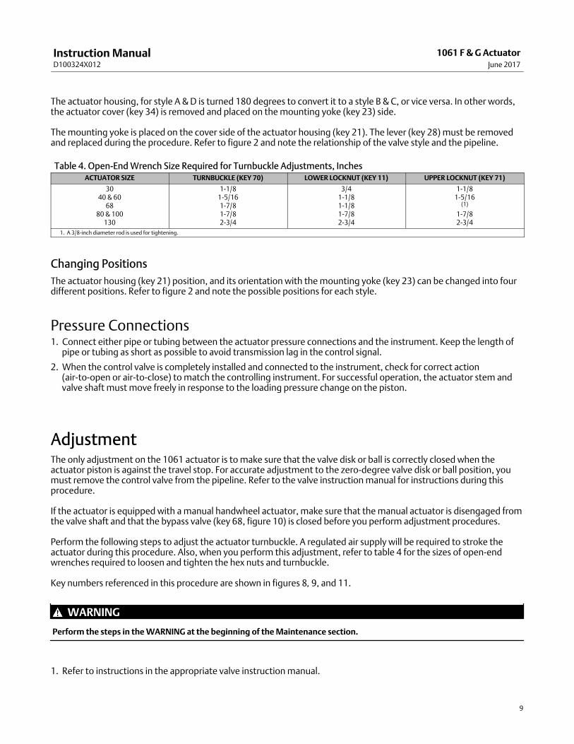
Table 4. Open‐End Wrench Size Required for Turnbuckle Adjustments, InchesACTUATOR SIZE TURNBUCKLE (KEY 70) LOWER LOCKNUT (KEY 11) UPPER LOCKNUT (KEY 71)
3040 & 60
6880 & 100
130
1‐1/81‐5/161‐7/81‐7/82‐3/4
3/41‐1/81‐1/81‐7/82‐3/4
1‐1/81‐5/16
(1)
1‐7/82‐3/4
1. A 3/8‐inch diameter rod is used for tightening.
Changing Positions
The actuator housing (key 21) position, and its orientation with the mounting yoke (key 23) can be changed into fourdifferent positions. Refer to figure 2 and note the possible positions for each style.
Pressure Connections1. Connect either pipe or tubing between the actuator pressure connections and the instrument. Keep the length of
pipe or tubing as short as possible to avoid transmission lag in the control signal.
2. When the control valve is completely installed and connected to the instrument, check for correct action(air‐to‐open or air‐to‐close) to match the controlling instrument. For successful operation, the actuator stem andvalve shaft must move freely in response to the loading pressure change on the piston.
AdjustmentThe only adjustment on the 1061 actuator is to make sure that the valve disk or ball is correctly closed when theactuator piston is against the travel stop. For accurate adjustment to the zero‐degree valve disk or ball position, youmust remove the control valve from the pipeline. Refer to the valve instruction manual for instructions during thisprocedure.
If the actuator is equipped with a manual handwheel actuator, make sure that the manual actuator is disengaged fromthe valve shaft and that the bypass valve (key 68, figure 10) is closed before you perform adjustment procedures.
Perform the following steps to adjust the actuator turnbuckle. A regulated air supply will be required to stroke theactuator during this procedure. Also, when you perform this adjustment, refer to table 4 for the sizes of open‐endwrenches required to loosen and tighten the hex nuts and turnbuckle.
Key numbers referenced in this procedure are shown in figures 8, 9, and 11.
WARNING
Perform the steps in the WARNING at the beginning of the Maintenance section.
1. Refer to instructions in the appropriate valve instruction manual.
Instruction ManualD100324X012
1061 F & G ActuatorJune 2017
10
2. Remove the access plate (key 72). Also remove the machine screws (key 73) if present.
Note
The cover (key 34) supports the outer end of the valve shaft and should not be removed during actuator adjustment.
3. Stroke the actuator until you can reach the lower hex nut (key 11) through the access opening. Loosen the hex nut.
4. Stroke the actuator until you can reach the left‐hand threaded upper hex nut (key 71) through the access opening.Loosen the hex nut.
5. Perform one of the following:
a. Push‐down‐to‐close (extending piston rod closes the valve): Slowly stroke the actuator to the down travel stop.Refer to the appropriate valve instruction manual to determine the closed position of the valve. Adjust theturnbuckle (key 70) until the valve is in the closed position. Lock this adjustment with the left‐hand threaded hexnut (key 71). Stroke the actuator to the up travel stop, and tighten the lower hex nut (key 11). Check threadengagement distance. The thread engagement should be the distance of the diameter of the thread. Tighten thelower hex nut (key 11) using the torque values shown in table 3.
b. Push‐down‐to‐open (extending piston rod opens the valve): Stroke the actuator to the up travel stop. Refer tothe appropriate valve instruction manual to determine the closed position of the valve. Check the valve position.Stroke the actuator until you reach the turnbuckle (key 70) through the access opening. Adjust the linkage.Stroke the actuator to the up travel stop again, and check the new adjustment. Continue this procedure until thevalve is in the closed position when the actuator piston is resting against the up travel stop. Check threadengagement distance. The thread engagement should be the distance of the diameter of the thread. Tighten thelower hex nut (key 11) using the torque values shown in table 3.
6. Replace the access plate (key 72).
7. Loosen the self‐tapping screws (key 39), and adjust the travel indicator (key 38). Re‐tighten the self‐tapping screws.
CAUTION
If using a handwheel actuator, the valve shaft spline could be damaged if excessive torque is applied to the valve shaft bythe manual actuator while the 1061 power actuator is stopped at either end of travel. To protect the valve shaft, performthe travel stop adjustment procedure found in the separate handwheel actuator instruction manual.
MaintenanceActuator parts are subject to normal wear and must be inspected and replaced as necessary. The frequency ofinspection and replacement depends upon the severity of service conditions. Instructions are given below fordisassembly and replacement of parts.
WARNING
Avoid personal injury or property damage from sudden release of process pressure or uncontrolled movement of parts.Before performing any maintenance operations:
� Do not remove the actuator from the valve while the valve is still pressurized.
Instruction ManualD100324X012
1061 F & G ActuatorJune 2017
11
� Always wear protective gloves, clothing, and eyewear when performing any maintenance operations to avoid personalinjury.
� Disconnect any operating lines providing air pressure, electric power, or a control signal to the actuator. Be sure theactuator cannot suddenly open or close the valve.
� Use bypass valves or completely shut off the process to isolate the valve from process pressure. Relieve process pressurefrom both sides of the valve. Drain the process media from both sides of the valve.
� Vent the power actuator loading pressure.
� Use lock‐out procedures to be sure that the above measures stay in effect while you work on the equipment.
� The valve packing box may contain process fluids that are pressurized, even when the valve has been removed from thepipeline. Process fluids may spray out under pressure when removing the packing hardware or packing rings, or whenloosening the packing box pipe plug.
� Check with your process or safety engineer for any additional measures that must be taken to protect against processmedia.
Key numbers are shown in figures 8, 9 and 11.
Disassembly
The following procedure describes how to completely disassemble the actuator. When inspecting and replacing parts,perform only those steps necessary to accomplish the repair.
1. Isolate the control valve from the line pressure, release pressure from both sides of the valve body, and drain theprocess media from both sides of the valve. Use lock‐out procedures to be sure that the above measures stay ineffect while you work on the equipment. Refer to instructions in the appropriate valve instruction manual.
2. Remove the positioner, if one is used. If necessary, refer to the positioner instruction manual for removalinstructions.
3. Unscrew the cap screws and washers (keys 35 and 76), and remove the cover (key 34). If an optional manualhandwheel actuator is used, it will be removed with the cover. Refer to the separate handwheel actuator instructionmanual for instructions.
4. Remove the retaining ring (key 31). If necessary, remove the travel indicator (key 38), by removing the screws (key29) from the hub (key 30).
5. Inspect, and if necessary, replace the cover bushing (key 32). Remove the travel indicator scale (key 36) byremoving the self‐tapping screws (key 37). Press the bushing out of the cover (key 34).
6. Remove the cap screw and hex nut (keys 13 and 14) for size 30, 40, 60, and 68 actuators; the hex nut and washer(keys 85 and 84) for size 80 and 100 actuators; or the cap screw and heavy hex nut for size 130 (key 13 and 85).
7. Note the lever/valve shaft orientation. Loosen cap screw (key 29). For size 80, 100 and 130 actuators, rotate setscrew (key 82) clockwise slightly to spread the split portion of the lever (key 28).
CAUTION
When removing the actuator from the valve, do not use a hammer or similar tool to drive the lever (key 28) off the valveshaft. Driving the lever could damage internal valve parts. On some valves, driving the lever off the shaft could move thevalve disk or ball and bearings away from the centered position, causing subsequent damage to valve parts as the valve isoperated.
If necessary, use a wheel puller to remove the lever from the valve shaft. It is permissible to tap the wheel puller screwlightly to loosen the lever, but hitting the screw with excessive force could damage valve parts or disrupt the centeredposition of the valve disk or ball and bearings.
Instruction ManualD100324X012
1061 F & G ActuatorJune 2017
12
8. For size 30, 40, and 68 actuators, unscrew cap screws (key 6) and remove cylinder cap (key 4). Inspect and, ifnecessary, replace the O‐ring (key 5).
9. Remove rod end bearing (key 12) and hex nut (key 11), remove the turnbuckle (key 70) and hex nut (key 71).
10. Remove cap screws (key 3) and slide the cylinder assembly (key 1) from the cylinder flange (key 2).
11. Pull the piston (key 7) and piston rod (key 10) from the cylinder assembly.
12. Inspect and, if necessary, replace the O‐rings (keys 8 and 16).
13. To separate the piston (key 7) from the piston rod (key 10), unscrew the cap screw or hex nut and washer (keys 9and 77) for size 30, 40, 60 and 68 actuators or the hex nut (key 86) for size 80 and 100 actuators.
14. For the size 130 actuator, a piston rod disassembly fixture (figure 4) is recommended to properly disassemble thepiston from the piston rod. Consult your Emerson sales office or Local Business Partner if this assembly must bedisassembled.
15. Unscrew the cap screws (key 22) and remove the cylinder flange (key 2), sliding seal (key 19), and seal supportcylinder (key 20).
16. Inspect, and if necessary, replace the O‐rings (keys 17 and 18) and thrust washer (key 74).
17. Unscrew the cap screws (key 24) from the mounting yoke, and remove the actuator housing assembly (key 21).
18. Unscrew the mounting yoke (key 23) from the valve by removing the valve mounting cap screws. Slide the yokeoff the valve shaft.
19. Inspect, and if necessary replace the mounting yoke bushing (key 81). It may be necessary to press out thebushing.
Assembly
This procedure assumes that the actuator was completely disassembled. If the actuator was not completelydisassembled, start these instructions at the appropriate step. This procedure also assumes that the valve is removedfrom the pipeline for ease in actuator assembly and adjustment.
Key numbers used in the following procedures are shown in figures 8, 9, and 11.
Note
Many of the replacement mounting yokes (key 23) are available only as assemblies that also include the bushing (key 81).However, replacement bushings are also available separately (see the Parts List).
1. If the bushing (key 81) was removed, press in the new bushing. The end of the bushing should be flush with thebottom of the recess in the mounting yoke (key 23).
2. Slide the mounting yoke over the valve shaft, and secure it to the valve with the valve mounting cap screws.
3. Tighten the valve mounting cap screws to the bolting torque values given in table 2.
WARNING
Refer to table 3 for bolt torque requirements. Exceeding any torque requirements could damage actuator parts andprevent safe operation. Refer to the Warning at the beginning of the Installation section in this manual.
Note
The cap screws torque values shown in table 3 are for final assembly.
Instruction ManualD100324X012
1061 F & G ActuatorJune 2017
13
4. Refer to figure 2 for the desired orientation of the housing (key 21). Secure the housing to the mounting yoke withthe cap screws (key 24).
5. Apply lithium grease lubricant (key 93) to the surfaces of the sliding seal (key 19). Refer to torque values shown intable 3. Be sure the O‐rings (keys 17 and 18) are inserted correctly.
Note
When assembling parts, make sure that all O‐rings are positioned correctly as shown in figures 8, 9, and 11.
6. Install the seal support cylinder (key 20), the thrust washer (key 74), the sliding seal, and the cylinder flange (key 2)and secure these parts with the cap screws (key 22).
7. If 60‐degree rotation is specified, a travel stop (key 15) will be threaded into the cylinder flange on size 30 to 100.For size 130, a travel stop and travel stop sleeve (keys 15 and 6) will be put into the cylinder flange.
8. Apply lithium grease lubricant (key 93) to the valve shaft. Refer to the appropriate valve instruction manual forlever/valve shaft orientation marks, and slide the lever (key 28) into place. See figure 3 for correct lever operatingclearance.
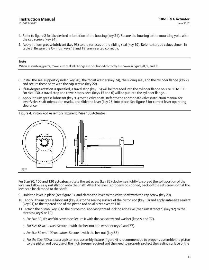
Figure 4. Piston Rod Assembly Fixture for Size 130 Actuator
58B3070E0577
For Size 80, 100 and 130 actuators, rotate the set screw (key 82) clockwise slightly to spread the split portion of thelever and allow easy installation onto the shaft. After the lever is properly positioned, back‐off the set screw so that thelever can be clamped to the shaft.
9. Hold the lever in place (see figure 3), and clamp the lever to the valve shaft with the cap screw (key 29).
10. Apply lithium grease lubricant (key 93) to the sealing surface of the piston rod (key 10) and apply anti‐seize sealant(key 91) to the tapered end of the piston rod on all sizes except 130.
11. Attach the piston (key 7) to the piston rod, applying thread locking adhesive (medium strength) (key 92) to thethreads (key 9 or 10):
a. For Size 30, 40, and 60 actuators: Secure it with the cap screw and washer (keys 9 and 77).
b. For Size 68 actuators: Secure it with the hex nut and washer (keys 9 and 77).
c. For Size 80 and 100 actuators: Secure it with the hex nut (key 86).
d. For the Size 130 actuator a piston rod assembly fixture (figure 4) is recommended to properly assemble the pistonto the piston rod because of the high torque required and the need to properly protect the sealing surface of the
Instruction ManualD100324X012
1061 F & G ActuatorJune 2017
14
piston rod. Consult your Emerson sales office or Local Business Partner for additional information to properlyassemble these parts.
e. Tighten the screw or nut to the torque specified in table 3.
12. Insert the piston and piston rod assembly down through the sliding seal (key 19). Attach the hex nut (key 71),turnbuckle (key 70), hex nut (key 11), and rod end bearing (key 12) to the piston rod assembly.
13. Rotate the lever to align with the rod end bearing. This connection can be aided by carefully moving the piston/rodassembly up or down.
14. Apply thread locking adhesive (medium strength) (key 92) or equivalent thread‐locking compound to the threadsof the cap screw (key 13).
15. Connecting the lever to the rod:
� For Size 30, 40, 60, and 68 actuators: Connect the lever and the rod end bearing with the cap screw and hex nut (keys13 and 14).
� For Size 80, 100, and 130 actuators: Connect the lever and the rod end bearing with the cap screw, washer, and hexnut (keys 13, 84, and 85). Size 130 does not require the washer (key 84).
16. Install the O‐ring (key 8 or 16) on the piston edge. Apply lithium grease lubricant (key 93) to the inside wall of thecylinder. Install the cylinder (key 1).
17. Attach the cylinder assembly (key 1) to the cylinder flange with the cap screws (key 3).
Size 130 has a mark on the cylinder flange that must align with a mark near the top of the housing flange.
18. For Size 30, 40, and 68 actuators, Place the O‐ring (key 5) in the cylinder cap, replace the cylinder cap (key 4), andsecure it to the cylinder assembly with the cap screws (key 6). Tighten all cap screws to the torques specified intable 3.
19. Install the hub (key 30) plus bushing (key 32) into the cover (key 34), and secure with the retaining ring (key 31).
20. Replace the travel indicator scale (key 36), and secure it with the self‐tapping screws (key 37). Install the travelindicator (key 38), and secure it with the self‐tapping screws (key 39).
21. Note the valve disk or ball position and direction of rotation.
WARNING
To avoid possible personal injury, do not stroke the actuator while the cover (key 34) is off.
a. If no handwheel actuator is to be used, position the travel indicator (key 38) according to the valve disk or ballposition just noted. Replace the cover (key 34) and secure it with the cap screws and washers (key 35 and 76). Ifthe holes in the cover and housing do not align, temporarily loosen the cap screws (key 24) and shift the housingslightly. Do not stroke the actuator while the cover is off.
b. If the actuator is equipped with a manual handwheel actuator, refer to the separate instruction manual formounting procedures.
22. If a positioner is to be used, refer to the separate valve positioner instruction manual for proper installation.
23. Follow the instructions in the Adjustment section for correct actuator turnbuckle adjustment.
Locking MechanismTo add the locking mechanism to an existing actuator, purchase the retrofit kit to install this modification or orderindividual parts from your Emerson sales officeor Local Business Partner. Replacement parts are shown in the Parts Listsection.
Instruction ManualD100324X012
1061 F & G ActuatorJune 2017
15
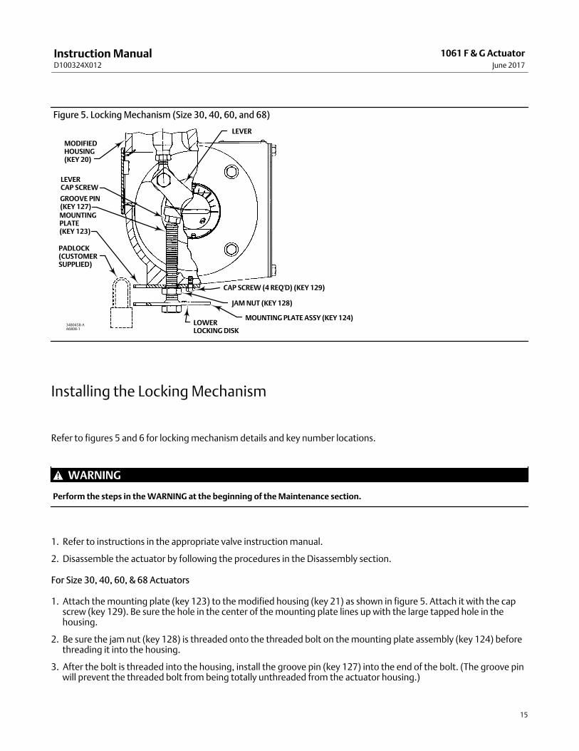
Figure 5. Locking Mechanism (Size 30, 40, 60, and 68)
MODIFIEDHOUSING(KEY 20)
PADLOCK(CUSTOMERSUPPLIED)
CAP SCREW (4 REQ'D) (KEY 129)
LEVER
34B0458‐AA6808-1
LEVER CAP SCREW
GROOVE PIN(KEY 127)
JAM NUT (KEY 128)
MOUNTING PLATE ASSY (KEY 124)LOWER LOCKING DISK
MOUNTINGPLATE(KEY 123)
Installing the Locking Mechanism
Refer to figures 5 and 6 for locking mechanism details and key number locations.
WARNING
Perform the steps in the WARNING at the beginning of the Maintenance section.
1. Refer to instructions in the appropriate valve instruction manual.
2. Disassemble the actuator by following the procedures in the Disassembly section.
For Size 30, 40, 60, & 68 Actuators
1. Attach the mounting plate (key 123) to the modified housing (key 21) as shown in figure 5. Attach it with the capscrew (key 129). Be sure the hole in the center of the mounting plate lines up with the large tapped hole in thehousing.
2. Be sure the jam nut (key 128) is threaded onto the threaded bolt on the mounting plate assembly (key 124) beforethreading it into the housing.
3. After the bolt is threaded into the housing, install the groove pin (key 127) into the end of the bolt. (The groove pinwill prevent the threaded bolt from being totally unthreaded from the actuator housing.)
Instruction ManualD100324X012
1061 F & G ActuatorJune 2017
16
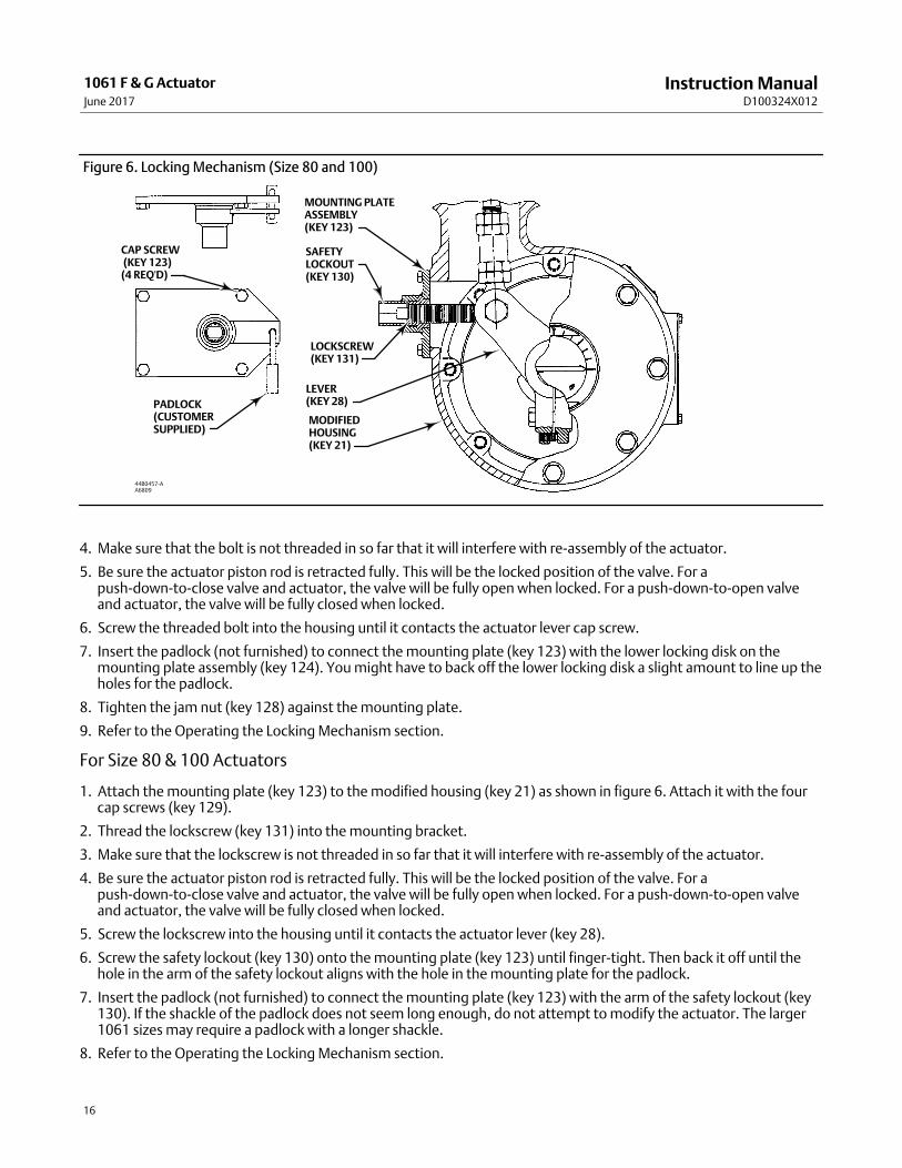
Figure 6. Locking Mechanism (Size 80 and 100)
MOUNTING PLATEASSEMBLY(KEY 123)
SAFETYLOCKOUT(KEY 130)
LOCKSCREW(KEY 131)
MODIFIEDHOUSING(KEY 21)
LEVER(KEY 28)
CAP SCREW (KEY 123)(4 REQ'D)
PADLOCK(CUSTOMERSUPPLIED)
44B0457‐AA6809
4. Make sure that the bolt is not threaded in so far that it will interfere with re‐assembly of the actuator.
5. Be sure the actuator piston rod is retracted fully. This will be the locked position of the valve. For apush‐down‐to‐close valve and actuator, the valve will be fully open when locked. For a push‐down‐to‐open valveand actuator, the valve will be fully closed when locked.
6. Screw the threaded bolt into the housing until it contacts the actuator lever cap screw.
7. Insert the padlock (not furnished) to connect the mounting plate (key 123) with the lower locking disk on themounting plate assembly (key 124). You might have to back off the lower locking disk a slight amount to line up theholes for the padlock.
8. Tighten the jam nut (key 128) against the mounting plate.
9. Refer to the Operating the Locking Mechanism section.
For Size 80 & 100 Actuators
1. Attach the mounting plate (key 123) to the modified housing (key 21) as shown in figure 6. Attach it with the fourcap screws (key 129).
2. Thread the lockscrew (key 131) into the mounting bracket.
3. Make sure that the lockscrew is not threaded in so far that it will interfere with re‐assembly of the actuator.
4. Be sure the actuator piston rod is retracted fully. This will be the locked position of the valve. For apush‐down‐to‐close valve and actuator, the valve will be fully open when locked. For a push‐down‐to‐open valveand actuator, the valve will be fully closed when locked.
5. Screw the lockscrew into the housing until it contacts the actuator lever (key 28).
6. Screw the safety lockout (key 130) onto the mounting plate (key 123) until finger‐tight. Then back it off until thehole in the arm of the safety lockout aligns with the hole in the mounting plate for the padlock.
7. Insert the padlock (not furnished) to connect the mounting plate (key 123) with the arm of the safety lockout (key130). If the shackle of the padlock does not seem long enough, do not attempt to modify the actuator. The larger1061 sizes may require a padlock with a longer shackle.
8. Refer to the Operating the Locking Mechanism section.
Instruction ManualD100324X012
1061 F & G ActuatorJune 2017
17
Operating the Locking MechanismKey numbers are located in figures 5 and 6.
To Unlock the Actuator (Size 30, 40, 60, & 68)
1. Remove the padlock. Loosen the jam nut (key 128, figure 5), and unscrew the threaded bolt until it is stopped bythe groove pin (key 127) in the threaded bolt.
Note
For normal operation of the actuator, the threaded bolt must be unscrewed far enough so that the actuator lever will not contactthe bolt in normal actuator operation.
2. If you are going to leave the bolt threaded into the housing, lock it with the jam nut (key 128) so that it cannot bescrewed into the housing and interfere with normal actuator operation.
To Unlock the Actuator (Size 80 & 100)
1. Remove the padlock. Remove the safety lockout (key 130, figure 6) and unscrew the lockscrew until it is free of thelever path.
Note
For normal operation of the actuator, the threaded bolt must be unscrewed far enough so that the actuator lever will not contactthe bolt in normal actuator operation. A good rule of thumb is to unscrew the lockscrew until it is approximately even with theoutward edge of the safety lockout when installed.
2. If you are going to leave the bolt threaded into the housing, reinstall the safety lockout and padlock.
To Lock the Actuator (Size 30, 40, 60, & 68)
1. Be sure the actuator piston rod is retracted fully. This will be the locked position of the valve. For apush‐down‐to‐close valve and actuator, the valve will be fully open when locked. For a push‐down‐to‐open valveand actuator, the valve will be fully closed when locked.
2. Be sure the jam nut (key 128, figure 5) is loose. Then, screw the threaded bolt into the housing until it contacts thehead on the cap screw of the actuator lever.
3. Rotate the threaded bolt until one of the holes in the lower locking disk (which is welded to the bolt) is in line withthe hole in the mounting plate (key 123). Tighten the jam nut against the mounting plate.
4. Lock the plate and disk together with a padlock (not furnished).
To Lock the Actuator (Size 80 & 100)
1. Be sure the actuator piston rod is retracted fully. This will be the locked position of the valve. For apush‐down‐to‐close valve and actuator, the valve will be fully open when locked. For a push‐down‐to‐open valveand actuator, the valve will be fully closed when locked.
2. Screw the lockscrew (key 131) into the housing until it contacts the actuator lever (key 28, figure 9).
3. Screw the safety lockout (key 130) onto the mounting plate (key 123) until finger‐tight. Then back it off until thehole in the arm of the safety lockout aligns with the hole in the mounting plate for the padlock.
4. Insert and lock the padlock (not furnished) to connect the mounting plate (key 123) with the arm of the safetylockout (key 130). The larger 1061 sizes may require a padlock with a longer shackle.
Instruction ManualD100324X012
1061 F & G ActuatorJune 2017
18
Pipe‐Away VentSome applications require venting of gas from the rotary actuator housing. The 3610 Series positioners vent into theactuator housing, and from there, the gas has numerous avenues of escape.
WARNING
If a flammable, hazardous, or reactive gas is used as the supply pressure medium, personal injury or property damage couldresult from fire or explosion of accumulated gas or from contact with hazardous or reactive gas.
The positioner on the control valve assembly does not form a gas‐tight seal. If the assembly is in an enclosed area, use aremote vent line, and use other safety measures to adequately ventilate the assembly. A remote vent pipe alone cannot berelied upon to remove all hazardous gas.
Vent line piping should comply with local and regional codes. It should be as short as possible with adequate insidediameter and few bends to remove exhaust gases to a ventilated area.
Note
This modification is NOT intended to be a leak‐proof or pressure‐tight design. It is intended to aid in containing the gas that ventsfrom the positioner and allow for connection of piping to carry it away.
The Parts List section, at the end of this manual, provides...
� Retrofit kit numbers to modify an actuator for the vent piping
� Replacement parts for pipe‐away vents
� Retrofit kit numbers for modification of units in the field
Take care that adequate vent pipe size is used. This is particularly important with the larger size actuators with faststroking speed requirements. In these situations, large quantities of gas can be vented very quickly through thepositioner, and you must have adequate pipe‐away capability. Keep the vent piping as short as possible with fewbends.
Key numbers are shown in figure 7 unless otherwise noted. Refer to the actuator Disassembly and Assembly steps togain access to the following parts.
For installation and maintenance of the pipe‐away vent system, be sure to do the following:
WARNING
Perform the steps in the WARNING at the beginning of the Maintenance section.
Refer to instructions in the appropriate valve instruction manual.
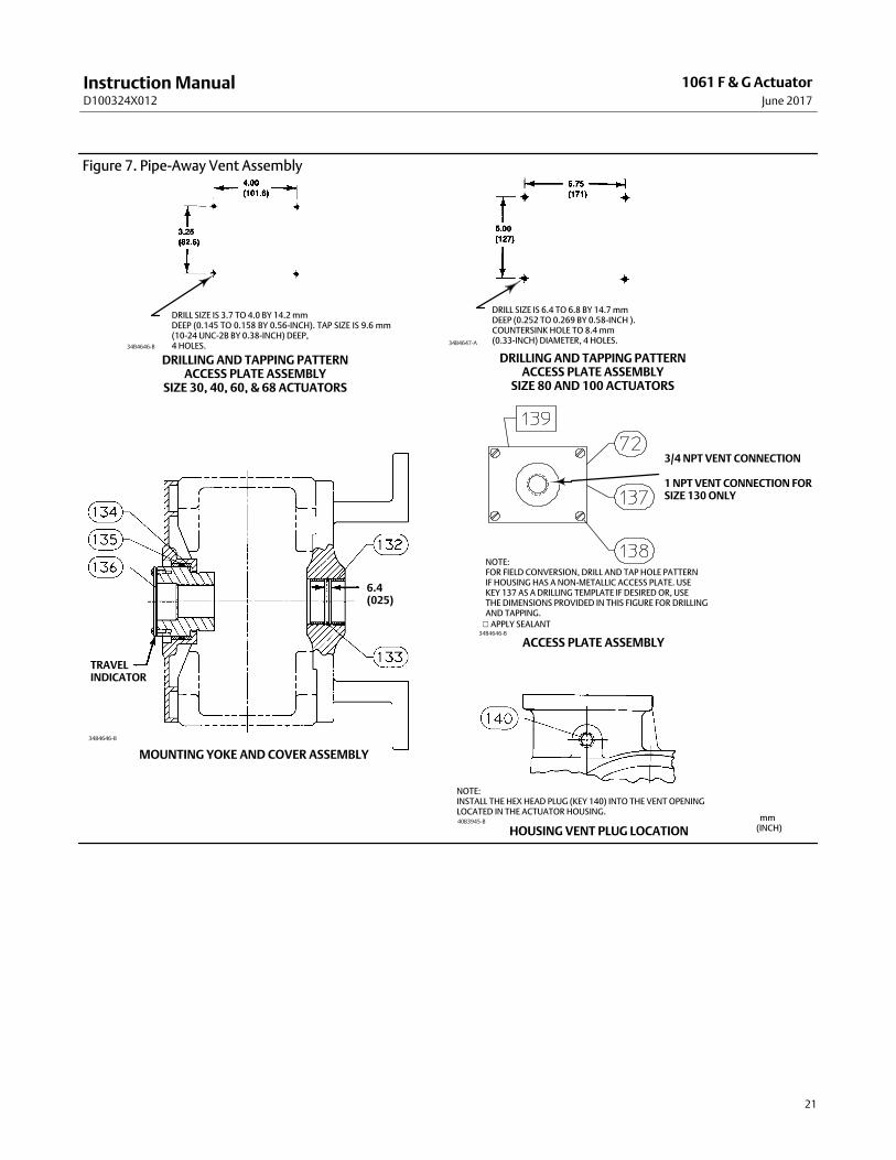
Bushings—Remove the mounting yoke bushing (key 67), and the end plate cover bushing (key 31, figures 9 and 11),then replace them with the pipe‐away vent parts. As shown in figure 7, the mounting yoke bushing (key 132) has twopieces with an O‐ring (key 133) between them. The end plate cover repeats the assembly with a two‐piece bushing(key 134) with an O‐ring between them (key 135).
Travel Indicator—A gasket (key 136) is placed under the travel indicator plate. Remove the indicator plate (key 37,figures 8, 9 and 11), install the gasket (key 136) as shown in figure 7.
Housing Vent Plug—A vent is provided in the housing design. To plug this opening, the pipe‐away vent kit provides ahex pipe plug (key 140) for this opening as shown in figure 7. Install the hex plug (key 140) into this opening andtighten it.
Instruction ManualD100324X012
1061 F & G ActuatorJune 2017
19
Parts OrderingWhen corresponding with your Emerson sales office or Local Business Partner about this equipment, refer to the serialnumber found on the actuator nameplate.
WARNING
Use only genuine Fisher replacement parts. Components that are not supplied by Emerson Automation Solutions shouldnot, under any circumstances, be used in any Fisher valve, because they may void your warranty, might adversely affect theperformance of the valve, and could cause personal injury and property damage.
Repair Kits
Actuator Repair Kits
Key Description Part Number
Actuator Repair Kits Include Keys 5, 8, 16, 17, 18, 56, and 74.
Size 30 R1061X00302
Size 40 R1061X00402
Size 60 R1061X00602
Size 68 R1061X00682
Size 80 R1061X00802
Size 100 R1061X01002
Pipe‐Away Vent Retrofit KitPipe‐Away Vent Kit Includes: Access Plate assembly, Two‐Piece Bushing,
Two O‐Rings, Gasket, and Sealant. See Figure 7.
Pipe‐Away Vent Retrofit Kit NumbersSHAFT DIAMETER
ACTUATOR SIZEKIT PARTNUMBERmm Inches
12.7 1/2 30 34B4646X022
15.9 5/8 30 34B4646X032
19.1 3/430 34B4646X042
40, 60, & 68 34B4646X052
22.2 7/830 34B4646X062
40, 60 & 68 34B4646X072
25.4 130 34B4646X082
40, 60, & 68 34B4646X092
31.8 1‐1/430 34B4646X102
40, 60 & 68 34B4646X112
38.1 1‐1/2 40, 60 & 68 34B4646X122
44.5 1‐3/4 40, 60, & 68 34B4646X132
50.8 2 40, 60 & 68 34B4646X142
50.8 2 80 & 100 34B4647X032
54.0 2‐1/8 80 & 100 34B4647X042
63.5 2‐1/2 80 & 100 34B4647X052
69.9 x 63.5to 101.6 x 63.5
2‐3/4 x 2‐1/2to 4 x 2‐1/2
100 34B4647X052
Parts List
Actuator Common Parts (figures 8, 9, & 11)
Note
Contact your Emerson sales office or Local Business Partner for Part
Ordering information.
Key Description
1 Cylinder Assembly
2 Cylinder Flange
3 Cap Screw
4 Cylinder Cap
5*(1) O‐Ring, nitrile
6 Cap Screw
7 Piston
8*(1) O‐Ring, nitrile
9 Cap Screw (for size 30, 40 & 60 only)
9 Hex Nut (for size 68 & 130 only)
10 Piston Rod
11 Hex Nut
12 Rod End Bearing
13 Cap Screw
14 Hex Nut
15 Travel Stop (not required for 90 degree rotation)
16*(1) O‐Ring, nitrile
17*(1) O‐Ring, nitrile
18*(1) O‐Ring, nitrile
19 Sliding Seal
20 Seal Support Cylinder
21 Housing
22 Cap Screw
23 Mounting Yoke
24 Cap Screw
28 Lever
29 Cap Screw
30 Hub
31 Retaining Ring
32* Bushing, fiberglass
34 Cover
35 Cap Screw
36 Travel Indicator Scale
37 Self Tapping Screw
*Recommended spare parts1. Included in repair kit.
Instruction ManualD100324X012
1061 F & G ActuatorJune 2017
20
Key Description
38 Travel Indicator
39 Self‐Tapping Screw
39 Cap Screw
40 Positioner plate
41 Cap Screw
42 Nameplate
43 Drive Screw
55 Vent Screen (Not shown)
56*(1) O‐Ring, nitrile (for size 30, 40 & 68 only)
(not shown)
Note
Key numbers 62 thru 68 and key 83 are used with bypass only (figure
10).
62 Connector
63 Elbow
64 Pipe Nipple
65 Pipe Plug
66 Pipe Cross
67 Tubing
68 Bypass Valve
70 Turnbuckle
71 Hex Nut
72 Access Plate
73 Machine Screw
74 Thrust Washer
76 Washer
77 Washer
81* Bushing (See following table)
82 Set Screw
83 Thread Locking Sealant (high strength)
84 Washer
85 Hex Nut
86 Hex Nut
87 Cap Screw
Key Description
90* O Ring
91 Anti‐Seize Sealant
92 Thread Locking Adhesive (medium strength)
93 Lithium Grease Lubricant
122 Thrust Washer
Locking Mechanism Parts (figure 5 or 6)123 Mounting Plate
124 Mounting Plate Assy
127 Groove Pin
128 Jam Nut
129 Cap Screw
130 Safety Lockout
131 Lockscrew
Pipe‐Away Vent Parts (figure 7)
Note
Complete Retrofit Kits are Listed at the Beginning of the Parts List. Use
This Listing for Individual Replacement Parts
132* Lined Bushing (Steel/PTFE) Yoke Side
133* O‐Ring (Nitrile)
134* Bushing (Steel/PTFE) Hub Side
135* O‐Ring (Nitrile) Hub Side
136 Travel Indicator Gasket
137 Access Plate Assembly
138 Machine Screw
139 RTV Blue or Equivalent
Silicon Gasket, #6B
140 Plug
Piston/Piston Rod Torquing FixtureSize 130
*Recommended spare parts1. Included in repair kit.
Instruction ManualD100324X012
1061 F & G ActuatorJune 2017
21
Figure 7. Pipe‐Away Vent Assembly
DRILL SIZE IS 3.7 TO 4.0 BY 14.2 mmDEEP (0.145 TO 0.158 BY 0.56‐INCH). TAP SIZE IS 9.6 mm(10‐24 UNC‐2B BY 0.38‐INCH) DEEP,4 HOLES.
DRILL SIZE IS 6.4 TO 6.8 BY 14.7 mm DEEP (0.252 TO 0.269 BY 0.58‐INCH ).COUNTERSINK HOLE TO 8.4 mm(0.33‐INCH) DIAMETER, 4 HOLES.
DRILLING AND TAPPING PATTERNACCESS PLATE ASSEMBLY
SIZE 30, 40, 60, & 68 ACTUATORS
DRILLING AND TAPPING PATTERNACCESS PLATE ASSEMBLY
SIZE 80 AND 100 ACTUATORS
ACCESS PLATE ASSEMBLY
MOUNTING YOKE AND COVER ASSEMBLY
HOUSING VENT PLUG LOCATION
3/4 NPT VENT CONNECTION
1 NPT VENT CONNECTION FORSIZE 130 ONLY
NOTE:FOR FIELD CONVERSION, DRILL AND TAP HOLE PATTERNIF HOUSING HAS A NON‐METALLIC ACCESS PLATE. USEKEY 137 AS A DRILLING TEMPLATE IF DESIRED OR, USETHE DIMENSIONS PROVIDED IN THIS FIGURE FOR DRILLINGAND TAPPING.
TRAVELINDICATOR
6.4(025)
NOTE:INSTALL THE HEX HEAD PLUG (KEY 140) INTO THE VENT OPENINGLOCATED IN THE ACTUATOR HOUSING.
� APPLY SEALANT
34B4646‐B34B4647‐A
34B4646‐B
34B4646‐B
40B3945‐B mm(INCH)
Instruction ManualD100324X012
1061 F & G ActuatorJune 2017
22
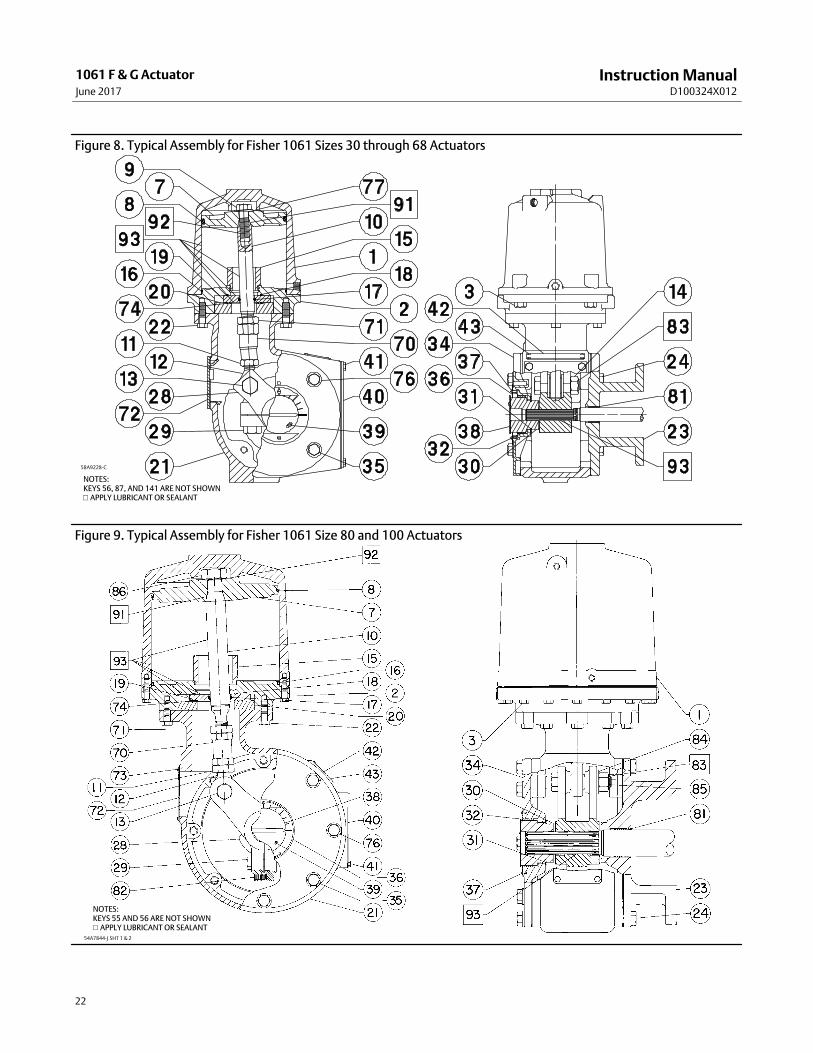
Figure 8. Typical Assembly for Fisher 1061 Sizes 30 through 68 Actuators
� APPLY LUBRICANT OR SEALANT
58A9228‐C
NOTES:KEYS 56, 87, AND 141 ARE NOT SHOWN
Figure 9. Typical Assembly for Fisher 1061 Size 80 and 100 Actuators
� APPLY LUBRICANT OR SEALANT
NOTES:KEYS 55 AND 56 ARE NOT SHOWN
54A7844‐J SHT 1 & 2
Instruction ManualD100324X012
1061 F & G ActuatorJune 2017
23
Figure 10. Partial View of Actuator with Bypass Valve
54A5326‐K
Instruction ManualD100324X012
1061 F & G ActuatorJune 2017
24
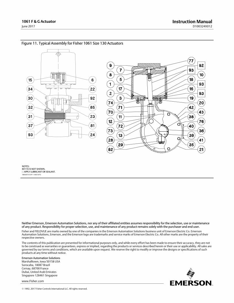
Figure 11. Typical Assembly for Fisher 1061 Size 130 Actuators
� APPLY LUBRICANT OR SEALANT.
NOTES:KEY 55 IS NOT SHOWN.
58B3057‐B SHT 1 AND SHT2
Emerson Automation Solutions Marshalltown, Iowa 50158 USASorocaba, 18087 BrazilCernay, 68700 FranceDubai, United Arab EmiratesSingapore 128461 Singapore
www.Fisher.com
The contents of this publication are presented for informational purposes only, and while every effort has been made to ensure their accuracy, they are notto be construed as warranties or guarantees, express or implied, regarding the products or services described herein or their use or applicability. All sales aregoverned by our terms and conditions, which are available upon request. We reserve the right to modify or improve the designs or specifications of suchproducts at any time without notice.
� 1992, 2017 Fisher Controls International LLC. All rights reserved.
Fisher and FIELDVUE are marks owned by one of the companies in the Emerson Automation Solutions business unit of Emerson Electric Co. EmersonAutomation Solutions, Emerson, and the Emerson logo are trademarks and service marks of Emerson Electric Co. All other marks are the property of theirrespective owners.
Neither Emerson, Emerson Automation Solutions, nor any of their affiliated entities assumes responsibility for the selection, use or maintenanceof any product. Responsibility for proper selection, use, and maintenance of any product remains solely with the purchaser and end user.