first ply failure study of composite conoidal shells used as roofing units in civil engineering
TRANSCRIPT
TECHNICAL ARTICLE—PEER-REVIEWED
First Ply Failure Study of Composite Conoidal ShellsUsed as Roofing Units in Civil Engineering
Kaustav Bakshi • Dipankar Chakravorty
Submitted: 26 February 2013 / in revised form: 3 July 2013
� ASM International 2013
Abstract In practical civil engineering, the necessity of
covering large column free open areas with shell surfaces is
often an issue. Such areas in medicinal plants and auto-
mobile industries prefer entry of north light through the
roofing units. Doubly curved singly ruled conoidal shells
are stiff and easy to fabricate as surfaces and fit excellently
to the above-mentioned industrial requirements. Today, the
engineers intend to use laminated composites to fabricate
these shell forms. Engineers are also concerned with the
performance evaluation of different stacking sequences to
maximize the stiffness for a given quantity of material
consumption. First ply failure load analysis of composite
plates appears abundantly in the literature, but on com-
posite shells, only a few papers are found (though not on
conoidal shells). This paper addresses an important issue
with which the practical engineers are often concerned
regarding performance evaluation of different laminations
(including antisymmetric and symmetric cross and angle
plies) in terms of first ply failure load of composite
conoids. The paper uses the finite element method as the
mathematical tool and concludes logically to a set of
inferences of practical engineering significance.
Keywords Composite materials � Conoidal shells �Finite element method � Failure investigations �Failure loads � Failure modes
Symbols
A Area of the shell
{d} Displacements of the shell
{de} Element displacements
E11, E22, E33 Elastic moduli
1, 2 and 3 Local coordinates of a lamina
G12, G23, G13 Shear moduli
ne Number of elements
Ryy Radius of curvature of the
conoidal shell along the ‘‘y’’ axis
Rxy Radius of cross curvature
of the conoidal shell
T Shear strength of lamina
Te Allowable shear strain of lamina
v/ Volume of the shell
XT, XC Normal strengths of lamina in tension
and compression, respectively
XeT, XeC Allowable normal strains of lamina
in tension and compression, respectively
�y y/b
YT, YC Normal strengths of matrix in
tension and compression,
respectively
YeT, YeC Allowable normal strains of matrix
in tension and compression,
respectively
mij Poisson’s ratio
r1, r2 Normal stresses acting along
1 and 2 axes of a lamina,
respectively
r6 Shear stress acting on 1–2 surface
of a lamina
sxy, sxz, syz Shear stresses of the shell
kx, ky, kxy Curvature changes of the shell
due to loading
K. Bakshi (&) � D. Chakravorty
Department of Civil Engineering, Jadavpur University,
Kolkata 700 032, India
e-mail: [email protected]
D. Chakravorty
e-mail: [email protected]
123
J Fail. Anal. and Preven.
DOI 10.1007/s11668-013-9725-y
Introduction
In civil engineering, it is advantageous to use thin shells
instead of flat plates to cover large column free open spaces
as one sees in airports, parking lots, hangers, and the like.
Doubly curved shell forms are more esthetically appealing
and rigid structures compared to the singly curved ones and
they enjoy a preference in the industry. Among the dif-
ferent doubly curved shell forms used in the civil
engineering, the conoidal shells are highly preferred by the
practicing engineers as these shells have ruled surfaces and
hence are easy to cast and fabricate. These shells are
esthetically appealing too. The civil engineers started to
use the laminated composites to fabricate the conoidal
shells from the second half of the last century as the high
specific stiffness and strength properties of these materials
result in less gravity forces and mass-induced forces
(seismic force) on the laminated shells compared to their
isotropic counterparts. All these taken together reduce the
foundation costs to a great extent.
Realizing the importance of laminated conoids in the
industry, different aspects of these shells are being reported
by different researchers even today. A number of
researchers like Nayak and Bandyopadhyay [1–3], Das and
Chakravorty [4–6], Kumari and Chakravorty [7, 8], and
Pradyumna and Bandyopadhyay [9, 10] are still working
on static bending, free and forced vibration responses of
conoidal shells. Free and forced vibration responses of the
conoidal shells were reported by Nayak and Bandyopad-
hyay [1–3]. Das and Chakravorty [4–6] used the finite
element method to study bending and free vibration char-
acteristics of graphite-epoxy conoidal shells with and
without stiffeners, while bending response of the delami-
nated graphite-epoxy conoidal shells was reported by
Kumari and Chakravorty [7, 8]. Pradyumna and Bandyo-
padhyay [9] carried out static bending and free vibration
investigations on laminated composite conoidal shells
using the higher-order shear deformation theory. The
authors [10] further worked on dynamic instability
behavior of laminated conoids.
As a wide spectrum of advantages is offered by the
composites, one needs to know and explore the material
characteristics comprehensively and failure study of these
materials is a part of that overall study. Failure of lami-
nated composites is progressive in nature (as it was
observed by Singh and Kumar [11], Akhras and Li [12],
and Ganesan and Liu [13]) initiating with the first ply
failure and finally culminating in the ultimate ply failure.
The aforesaid authors also reported that the ultimate failure
load of laminated composites is much higher than the
corresponding first ply failure load. Therefore, assigning
the engineering factor of safety to the first ply failure load
underestimates the ultimate material capacity and leads to a
highly conservative design. However, it is important to
know the load value at which failure initiates, otherwise the
latent damages progress gradually within the laminate and
lead to a sudden total ply failure under service conditions.
In a review of the literature to follow, the focus is on papers
published on first ply failure of composite plates and shells
and an attempt is made to identify an area where failure
study may be extended.
Pandey and Reddy [14] worked on first ply failure of
simply supported graphite-epoxy plates using the linear
strain displacement relationship and four-noded and nine-
noded Lagrangian elements. Linear and nonlinear first ply
failure loads of thin and thick plates subjected to transverse
and in-plane loads were reported by Reddy and Reddy [15].
Experimental first ply failure loads of centrally loaded
square plates were reported by Kam and Jan [16], Kam and
Sher [17], and Kam et al. [18]. The authors also carried out
theoretical failure investigations of those plates using lay-
erwise linear displacement theory [16], the Ritz method
[17], and finite element method [18]. It was also found that
the finite element method yields fairly close results to the
experimental values. Turvey and Osman [19] worked on
nonlinear failure of carbon-epoxy unsymmetrical cross-ply
laminated strips (i.e., large aspect ratio rectangular plates)
subjected to uniform lateral pressure. Linear and nonlinear
first ply failure loads of graphite-epoxy thick and thin
plates subjected to uniformly distributed load were repor-
ted by Sciuva et al. [20]. Cho and Yoon [21] used the
postprocess method to study first ply failure loads of cross-
ply laminated plates subjected to uniformly distributed and
sinusoidal loads. The proposed method was validated by
comparing the results with the values obtained from exact
elastic analysis and first-order shear deformation theory.
First and ultimate ply failure loads along with the buckling
loads of symmetrically laminated plates under positive and
negative in-plane shear were reported by Singh and Kumar
[11]. The buckling loads of the plates were found to be
considerably small when compared to the failure loads of
those plates. The first ply failure loads of stiffened plates
were studied by Ray and Satsangi [22] and Kumar and
Srivastava [23]. The authors used geometrically linear
finite element formulations in their studies. Chang and
Chiang [24] carried out experimental and theoretical first
ply failure investigations of laminated composite plates,
and a detailed review on damage modeling and finite ele-
ment analysis for composite laminates was reported by
Zheng and Liu [25]. Recently, Lal et al. [26] worked on
stochastic nonlinear failure analysis of laminated compos-
ite plates under compressive transverse loading. First ply
failure loads of cylindrical and spherical shell panels were
obtained by Prusty et al. [27]. The authors used linear finite
element formulation to evaluate first ply failure loads of
both bare and stiffened shells.
J Fail. Anal. and Preven.
123
The perusal of the literature reveals that research reports
on first ply failure loads of laminated composite plates are
available abundantly, but similar work on shells is much
less in general and absolutely missing for conoidal shells.
Although different behavioral aspects like static bending,
free vibration, and instability behaviors of laminated co-
noids are reported recently, a confident application of such
shells needs detailed knowledge about the load which the
shell is capable to withstand before failure. Hence, the
present study intends to report the first ply failure of uni-
formly loaded clamped composite conoidal shells using
established failure criteria. Moreover, the failure modes
and the failure tendencies in the case of interactive failure
and failure locations are studied critically to grossly
understand the failure behavior of the composite conoids.
A number of antisymmetric and symmetric cross and
angle-ply laminates are analyzed to find the lamination that
would best suit a practical situation with a given quantity of
material consumption.
Mathematical Formulation
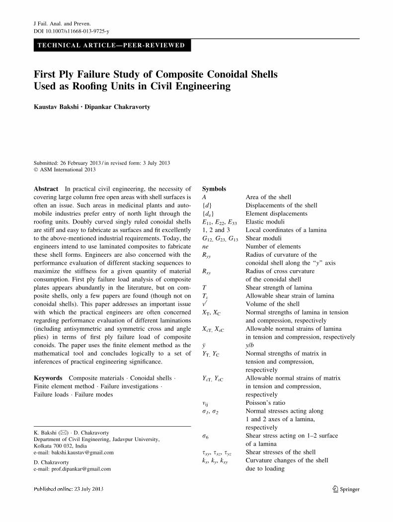
A doubly curved laminated composite conoidal shell
(Fig. 1) of uniform thickness h and radii of curvatures Ryy
and Rxy is considered in the present study. The thickness of
the conoidal shell (h) consists of any numbers of thin
laminae which are bonded together to form the laminate.
Fibers in each lamina of the composite shell are oriented
along the local axis of the lamina and at an angle h with
reference to the global x-axis (Fig. 1). The x and y axes are
taken at the mid-surface of the shell which has sides a and
b, respectively.
Strain–Displacement and Constitutive Relationship
of the Shell
First-order shear deformation theory is used in the present
study. The strain–displacement [B/] and constitutive rela-
tionship [D/] matrices of the shell adopted in the present
study are those used by Kumari and Chakravorty [8]. While
obtaining the shear stress resultants, proper shear correc-
tion factors (as used by Kumari and Chakravorty [8]) are
applied. Though the authors [8] worked on delaminated
conoids, the matrices ([B/], [D/], and [N]) adopted here are
for the undelaminated ones.
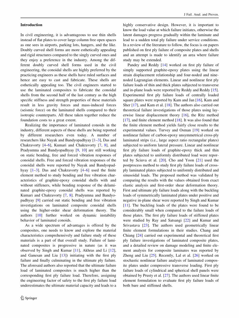
Finite Element Formulation
A displacement-based isoparametric finite element formu-
lation is developed in the present study using eight-noded
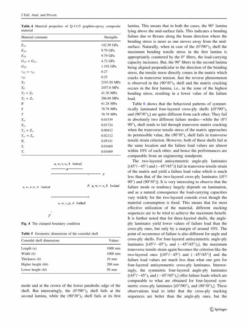
curved quadratic elements with C0 continuity as depicted in
Fig. 2. There are five degrees of freedom considered at
each node of the element including three displacements
Fig. 1 A uniformly loaded
laminated composite conoidal
shell
J Fail. Anal. and Preven.
123

(u, v, and w) and two rotations (a and b). The displacement u
is considered to act along the x-axis, v tangential to the mid-
surface, and w normal to it. The rotations a and b are acting
about y and x axes of the shell, respectively. The element
degrees of freedom {u} are interpolated from their nodal
values {de} with the help of the interpolation functions [N].
uf g ¼ N½ � def g
where uf g ¼ u v w a bf gTand ui vi wi ai bif g
i ¼ 1 to 8
The interpolation functions [N] used in the present for-
mulation are adopted from Kumari and Chakravorty [8].
Governing Equations
For an elastic continuum undergoing small deformations,
the governing differential equation is derived based on
minimization of the total potential energy. The total
potential energy p is expressed as sum of strain energy U
and work done due to external load W.
p ¼ U þW
Strain energy of the shell is expressed by the volume
integral,
U ¼ 1
2
Z
v=
egf T rgf dv ðEq 1Þ
By using the laminate constitutive relationship matrix
[D/], Eq. (1) can be written as,
U ¼ 1
2
ZZA
ef gTD=h i
ef gdxdy ðEq 2Þ
By using the strain–displacement matrix [B/], Eq. (2)
can be written as,
U ¼ 1
2
Z Z
A
B=h iT
df gTD=h i
B=h i
df g dxdy ðEq 3Þ
Work done by external load (W) is expressed as an area
integral,
W ¼ �Z Z
A
df gTqf g dA ðEq 4Þ
External load on the shell can be expressed as
qf g ¼ 0 0 qz 0 0f gT, where qz represents
transverse load intensity on the shell.
To minimize the total potential energy of the shell with
respect to its deformations, the shell has to satisfy the
following condition:
opofdg ¼ 0 ðEq 5Þ
Consider the laminated composite shell discretized into
ne elements. The strain energy and work done of the shell
are expressed, respectively, as
U ¼Xne
i¼1
Ui
¼ 1
2
Z Z
A
B=h iT
D=h i
B=h i
dxdy
24
35
i
def gTdef g
ðEq 6Þ
W ¼Xne
i¼1
Wi ¼ �Z Z
A
N½ �T q½ � dx dy
24
35
i
def gT ðEq 7Þ
By applying Eqs. (6) and (7), Eq. (5) can be written as,
Xne
i¼1
Z Z
A
B=h iT
D=h i
B=h i
dx dy
0@
1A
24
35
i
def g
�ZZ
A
½N�T ½q�� �
dxdy
� �i
¼ 0
Xne
i¼1
Ki½ � def g ¼ Qif g ðEq 8Þ
where Ki½ � ¼ ½R R
A
B=� �T
D=� �
B=� �
dx dy�i and Qif g ¼ ½R R
AN½ �T ½q�dx dy�i.The element stiffness matrix [Ki] and load vector {Qi}
are transformed to isoparametric coordinates n and g,
respectively, for numerical integration by 2 9 2 Gauss
quadrature rule. Global stiffness matrix and load vector are
obtained by assembling the element matrices with proper
transformations due to the curved geometry of the shell and
they are expressed as,
K½ � df g ¼ Qf g ðEq 9Þ
where K½ � ¼Pne
i¼1
Ki½ � and Q½ � ¼Pne
i¼1
Qi½ �.
Equation (9) is solved by the Gauss Elimination Method.
Fig. 2 The shell element
J Fail. Anal. and Preven.
123
Lamina Stress Calculation
The displacements of the laminated shell obtained from the
solution of Eq. (9) are used to obtain the strain vector. The
strains acting on the surface of a lamina situated at a dis-
tance z from the laminate mid-surface are evaluated in
global axes as
ex ¼ e0x þ zkx; ey ¼ e0
y þ zky and cxy ¼ c0xy þ zkxy ðEq 10Þ
where ex, ey are the strains acting along x and y axes of the
shell and cxy is the shear strain working on x–y surface. ex0,
ey0, and cxy
0 denote corresponding strains at the laminate
mid-surface.
Lamina strains are transformed from the global axes of
the shell to the local axes of the lamina using the trans-
formation matrix
e1
e2e6
2
9=;
8<: ¼
sin2 h cos2 h 2sinhcoshcos2 h sin2 h �2sinhcosh
� sinhcosh sinhcosh sin2 h� cos2 h
24
35 ex
eycxy
2
9=;
8<:ðEq 11Þ
where e1, e2 are the strains of lamina acting along the 1 and
2 axes. e6 is the shear strain working on 1–2 surfaces of the
lamina. Lamina stresses are obtained using the constitutive
relationship of the lamina.
r1
r2
r6
9=;
8<: ¼
Q11 Q12 0
Q12 Q22 0
0 0 Q66
24
35 e1
e2
e6
9=;
8<: ðEq 12Þ
where Q12 ¼ 1� m12m21ð Þ�1E11m21; Q11 ¼ 1� m12m21ð Þ�1
E11; Q22 ¼ 1� m12m21ð Þ�1E22, and Q66 = G12.
Well-accepted failure theories like the maximum stress,
maximum strain, Hoffman, Tsai-Hill, and Tsai-Wu failure
criterion are used to obtain the failure loads of the com-
posite conoid. The failure theories are adopted from Reddy
and Reddy [15].
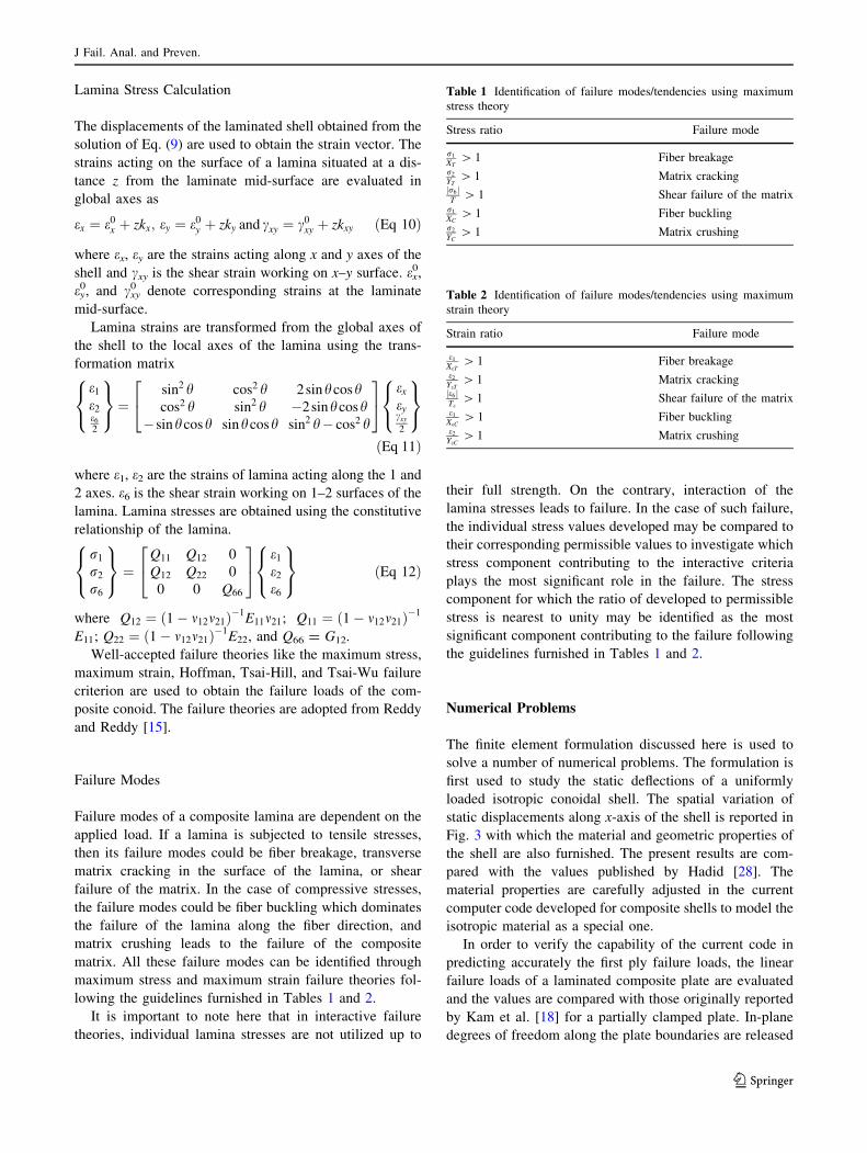
Failure Modes
Failure modes of a composite lamina are dependent on the
applied load. If a lamina is subjected to tensile stresses,
then its failure modes could be fiber breakage, transverse
matrix cracking in the surface of the lamina, or shear
failure of the matrix. In the case of compressive stresses,
the failure modes could be fiber buckling which dominates
the failure of the lamina along the fiber direction, and
matrix crushing leads to the failure of the composite
matrix. All these failure modes can be identified through
maximum stress and maximum strain failure theories fol-
lowing the guidelines furnished in Tables 1 and 2.
It is important to note here that in interactive failure
theories, individual lamina stresses are not utilized up to
their full strength. On the contrary, interaction of the
lamina stresses leads to failure. In the case of such failure,
the individual stress values developed may be compared to
their corresponding permissible values to investigate which
stress component contributing to the interactive criteria
plays the most significant role in the failure. The stress
component for which the ratio of developed to permissible
stress is nearest to unity may be identified as the most
significant component contributing to the failure following
the guidelines furnished in Tables 1 and 2.
Numerical Problems
The finite element formulation discussed here is used to
solve a number of numerical problems. The formulation is
first used to study the static deflections of a uniformly
loaded isotropic conoidal shell. The spatial variation of
static displacements along x-axis of the shell is reported in
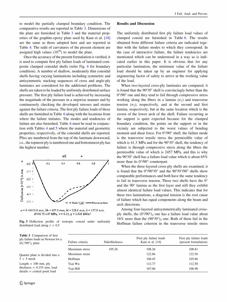
Fig. 3 with which the material and geometric properties of
the shell are also furnished. The present results are com-
pared with the values published by Hadid [28]. The
material properties are carefully adjusted in the current
computer code developed for composite shells to model the
isotropic material as a special one.
In order to verify the capability of the current code in
predicting accurately the first ply failure loads, the linear
failure loads of a laminated composite plate are evaluated
and the values are compared with those originally reported
by Kam et al. [18] for a partially clamped plate. In-plane
degrees of freedom along the plate boundaries are released
Table 1 Identification of failure modes/tendencies using maximum
stress theory
Stress ratio Failure mode
r1
XT[ 1 Fiber breakage
r2
YT[ 1 Matrix cracking
r6j jT
[ 1 Shear failure of the matrixr1
XC[ 1 Fiber buckling
r2
YC[ 1 Matrix crushing
Table 2 Identification of failure modes/tendencies using maximum
strain theory
Strain ratio Failure mode
e1
XeT[ 1 Fiber breakage
e2
YeT[ 1 Matrix cracking
e6j jTe
[ 1 Shear failure of the matrixe1
XeC[ 1 Fiber buckling
e2
YeC[ 1 Matrix crushing
J Fail. Anal. and Preven.
123
to model the partially clamped boundary condition. The
comparative results are reported in Table 3. Dimensions of
the plate are furnished in Table 3 and the material prop-
erties of the graphite-epoxy plate used by Kam et al. [18]
are the same as those adopted here and are reported in
Table 4. The radii of curvatures of the present element are
assigned high values (1030) to model the plate.
Once the accuracy of the present formulation is verified, it
is used to compute first ply failure loads of laminated com-
posite clamped conoidal shells (refer Fig. 4 for boundary
condition). A number of shallow, moderately thin conoidal
shells having varying laminations including symmetric and
antisymmetric stacking sequences of cross and angle-ply
laminates are considered for the additional problems. The
shells are taken to be loaded by uniformly distributed surface
pressure. The first ply failure load is achieved by increasing
the magnitude of the pressure in a stepwise manner and by
continuously checking the developed stresses and strains
against the failure criteria. The first ply failure loads of these
shells are furnished in Table 6 along with the locations from
where the failure initiates. The modes and tendencies of
failure are also furnished. Table 6 must be read in conjunc-
tion with Tables 4 and 5 where the material and geometric
properties, respectively, of the conoidal shells are reported.
Plies are numbered from the top of the laminate downward,
i.e., the topmost ply is numbered one and bottommost ply has
the highest number.
Results and Discussion
The uniformly distributed first ply failure load values of
clamped conoid are furnished in Table 6. The results
obtained from different failure criteria are indicated toge-
ther with the failure modes to which they correspond. In
the case of interactive failure, the failure tendencies are
mentioned which can be understood in a way as is indi-
cated earlier in this paper. It is obvious that for any
particular lamination, the minimum value of the failure
load should be taken up by an engineer for applying
engineering factor of safety to arrive at the working value
of the load.
When two-layered cross-ply laminates are compared, it
is found that the 90�/0� shell is convincingly better than the
0�/90� one and they tend to fail through compressive stress
working along the fibers in a lamina (r1) and transverse
tension (r2), respectively, and at the second and first
lamina, respectively, but at the same location which is the
crown of the lower arch of the shell. Failure occurring at
the support is quiet expected because for the clamped
boundary condition, the points on the support or in the
vicinity are subjected to the worst values of bending
moment and shear force. For 0�/90� shell, the failure mode
is the transverse tensile stress the permissible value of
which is 41.3 MPa and for the 90�/0� shell, the tendency of
failure is through compressive stress along the fibers the
permissible value of which is 2457 MPa, and this is why
the 90�/0� shell has a failure load value which is about 65%
more than its 0�/90� counterpart.
When the three-layered cross-ply shells are examined, it
is found that the 0�/90�/0� and the 90�/0�/90� shells show
comparable performances and both have the same tendency
to fail in transverse tension. These two shells have the 0�and the 90� lamina as the first layer and still they exhibit
almost identical failure load values. This indicates that for
these two laminations, a diagonal tension is the root cause
of failure which has equal components along the beam and
arch directions.
Among four-layered antisymmetrically laminated cross-
ply shells, the (0�/90�)2 one has a failure load value about
16% more than the (90�/0�)2 one. Both of them fail in the
Hoffman failure criterion in the transverse tensile stressFig. 3 Deflection profile of isotropic conoid under uniformly
distributed load along �y = 0.5
Table 3 Comparison of first
ply failure loads in Newton for a
(02�/90�)s plate
Quarter plate is divided into a
5 9 5 mesh
Length = 100 mm, ply
thickness = 0.155 mm, load
details = central point load
Failure criteria Side/thickness
First ply failure loads
Kam et al. [18]
First ply failure loads
(present formulation)
Maximum stress 105.26 108.26 108.81
Maximum strain 122.86 122.56
Hoffman 106.45 105.86
Tsai-Wu 112.77 112.50
Tsai-Hill 107.06 106.90
J Fail. Anal. and Preven.
123
mode and at the crown of the lower parabolic edge of the
shell. But interestingly, the (0�/90�)2 shell fails at the
second lamina, while the (90�/0�)2 shell fails at its first
lamina. This means that in both the cases, the 90� lamina
lying above the mid-surface fails. This indicates a bending
failure due to flexure along the beam direction where the
bending stress is more as one moves away from the mid-
surface. Naturally, when in case of the (0�/90�)2 shell the
maximum bending tensile stress in the first lamina is
appropriately countered by the 0� fibers, the load-carrying
capacity increases. But, the 90� fibers in the second lamina
being aligned perpendicular to the direction of the bending
stress, the tensile stress directly comes in the matrix which
cracks in transverse tension. Just the reverse phenomenon
is observed in the (90�/0�)2 shell and the matrix cracking
occurs in the first lamina, i.e., in the zone of the highest
bending stress, resulting in a lower value of the failure
load.
Table 6 shows that the behavioral patterns of symmet-
rically laminated four-layered cross-ply shells [(0�/90�)s
and (90�/0�)s] are quite different from each other. They fail
in absolutely two different failure modes—while the (0�/
90�)s shell tends to fail through transverse matrix cracking
when the transverse tensile stress of the matrix approaches
its permissible value, the (90�/0�)s shell fails in transverse
tensile strain criterion. However, both of these shells fail at
the same location and the failure load values are almost
within 10% of each other, and hence the performances are
comparable from an engineering standpoint.
The two-layered antisymmetric angle-ply laminates
[(45�/�45�) and (�45�/45�)] fail in transverse tensile strain
of the matrix and yield a failure load value which is much
less than that of the two-layered cross-ply laminates [(0�/
90�) and (90�/0�)]. It is very interesting to observe that the
failure mode or tendency largely depends on lamination,
and as a natural consequence the load-carrying capacities
vary widely for the two-layered conoids even though the
material consumption is fixed. This means that for most
effective utilization of the material, different stacking
sequences are to be tried to achieve the maximum benefit.
It is further noted that for three-layered shells, the angle-
ply laminates yield lower values of failure load than the
cross-ply ones, but only by a margin of around 10%. The
point of occurrence of failure is also different for angle and
cross-ply shells. For four-layered antisymmetric angle-ply
laminates [(45�/�45�)2 and (�45�/45�)2], the maximum
transverse tensile strain again becomes the criterion like the
two-layered ones [(45�/�45�) and (�45�/45�)] and the
failure load values are much less than what one gets for
four-layered antisymmetric cross-ply laminates. Interest-
ingly, the symmetric four-layered angle-ply laminates
[(45�/�45�)s and (�45�/45�)s] offer failure loads which are
comparable to what are obtained for four-layered sym-
metric cross-ply laminates [(0�/90�)s and (90�/0�)s]. These
observations lead to infer that the cross-ply stacking
sequences are better than the angle-ply ones, but the
Fig. 4 The clamped boundary condition
Table 5 Geometric dimensions of the conoidal shell
Conoidal shell dimensions Values
Length (a) 1000 mm
Width (b) 1000 mm
Thickness (h) 10 mm
Higher height (hh) 200 mm
Lower height (hl) 50 mm
Table 4 Material properties of Q-1115 graphite-epoxy composite
material
Material constants Strengths
E11 142.50 GPa
E22 9.79 GPa
E33 9.79 GPa
G12 = G13 4.72 GPa
G23 1.192 GPa
m12 = m13 0.27
m23 0.25
XT 2193.50 MPa
XC 2457.0 MPa
YT = ZT 41.30 MPa
YC = ZC 206.80 MPa
R 61.28 MPa
S 78.78 MPa
T 78.78 MPa
Xet 0.01539
Xec 0.01724
Yet = Zet 0.00412
Yec = Zec 0.02112
Re 0.05141
Se 0.01669
Te 0.01669
J Fail. Anal. and Preven.
123
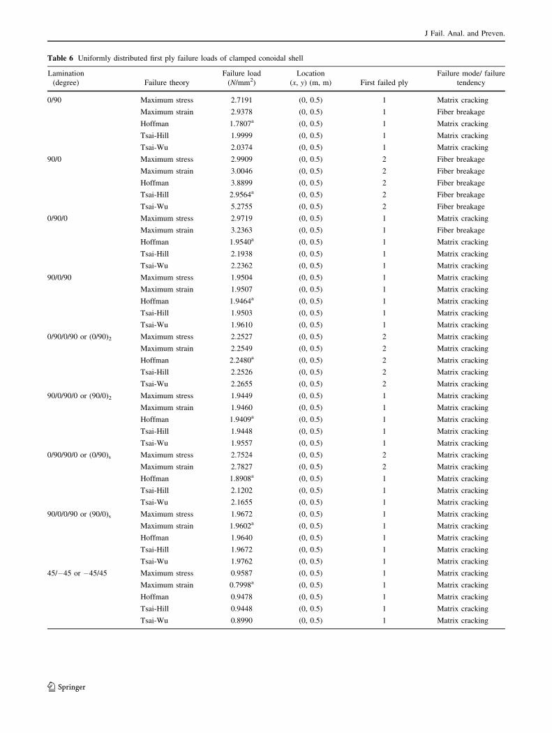
Table 6 Uniformly distributed first ply failure loads of clamped conoidal shell
Lamination
(degree) Failure theory
Failure load
(N/mm2)
Location
(x, y) (m, m) First failed ply
Failure mode/ failure
tendency
0/90 Maximum stress 2.7191 (0, 0.5) 1 Matrix cracking
Maximum strain 2.9378 (0, 0.5) 1 Fiber breakage
Hoffman 1.7807a (0, 0.5) 1 Matrix cracking
Tsai-Hill 1.9999 (0, 0.5) 1 Matrix cracking
Tsai-Wu 2.0374 (0, 0.5) 1 Matrix cracking
90/0 Maximum stress 2.9909 (0, 0.5) 2 Fiber breakage
Maximum strain 3.0046 (0, 0.5) 2 Fiber breakage
Hoffman 3.8899 (0, 0.5) 2 Fiber breakage
Tsai-Hill 2.9564a (0, 0.5) 2 Fiber breakage
Tsai-Wu 5.2755 (0, 0.5) 2 Fiber breakage
0/90/0 Maximum stress 2.9719 (0, 0.5) 1 Matrix cracking
Maximum strain 3.2363 (0, 0.5) 1 Fiber breakage
Hoffman 1.9540a (0, 0.5) 1 Matrix cracking
Tsai-Hill 2.1938 (0, 0.5) 1 Matrix cracking
Tsai-Wu 2.2362 (0, 0.5) 1 Matrix cracking
90/0/90 Maximum stress 1.9504 (0, 0.5) 1 Matrix cracking
Maximum strain 1.9507 (0, 0.5) 1 Matrix cracking
Hoffman 1.9464a (0, 0.5) 1 Matrix cracking
Tsai-Hill 1.9503 (0, 0.5) 1 Matrix cracking
Tsai-Wu 1.9610 (0, 0.5) 1 Matrix cracking
0/90/0/90 or (0/90)2 Maximum stress 2.2527 (0, 0.5) 2 Matrix cracking
Maximum strain 2.2549 (0, 0.5) 2 Matrix cracking
Hoffman 2.2480a (0, 0.5) 2 Matrix cracking
Tsai-Hill 2.2526 (0, 0.5) 2 Matrix cracking
Tsai-Wu 2.2655 (0, 0.5) 2 Matrix cracking
90/0/90/0 or (90/0)2 Maximum stress 1.9449 (0, 0.5) 1 Matrix cracking
Maximum strain 1.9460 (0, 0.5) 1 Matrix cracking
Hoffman 1.9409a (0, 0.5) 1 Matrix cracking
Tsai-Hill 1.9448 (0, 0.5) 1 Matrix cracking
Tsai-Wu 1.9557 (0, 0.5) 1 Matrix cracking
0/90/90/0 or (0/90)s Maximum stress 2.7524 (0, 0.5) 2 Matrix cracking
Maximum strain 2.7827 (0, 0.5) 2 Matrix cracking
Hoffman 1.8908a (0, 0.5) 1 Matrix cracking
Tsai-Hill 2.1202 (0, 0.5) 1 Matrix cracking
Tsai-Wu 2.1655 (0, 0.5) 1 Matrix cracking
90/0/0/90 or (90/0)s Maximum stress 1.9672 (0, 0.5) 1 Matrix cracking
Maximum strain 1.9602a (0, 0.5) 1 Matrix cracking
Hoffman 1.9640 (0, 0.5) 1 Matrix cracking
Tsai-Hill 1.9672 (0, 0.5) 1 Matrix cracking
Tsai-Wu 1.9762 (0, 0.5) 1 Matrix cracking
45/�45 or �45/45 Maximum stress 0.9587 (0, 0.5) 1 Matrix cracking
Maximum strain 0.7998a (0, 0.5) 1 Matrix cracking
Hoffman 0.9478 (0, 0.5) 1 Matrix cracking
Tsai-Hill 0.9448 (0, 0.5) 1 Matrix cracking
Tsai-Wu 0.8990 (0, 0.5) 1 Matrix cracking
J Fail. Anal. and Preven.
123
differences in performance are most noticeable when the
number of layers is two, and with gradual increase in
number of lamina, the performances are somewhat
comparable.
An overall analysis of failure loads for different lami-
nations clearly indicates that the (90�/0�) and (0�/90�)2
shells are very good in terms of stiffness among which
again the (90�/0�) one is the best choice. A two-layered
laminate is easy to fabricate and an engineer should prac-
tically pick up the (90�/0�) lamination to fabricate the
conoidal shell surface if he has a number of options as
given in Table 6. The general behavior of different lami-
nations in terms of their failure load values indicates a
complex interaction between stacking sequence and shell
curvature and it is very difficult to arrive at a unified
conclusion unless the numerical experimentation is done.
Conclusions
The present finite element code is capable of successfully
assessing the first ply failure loads of laminated composite
conoidal shells. The two-layered cross-ply shells fail in the
bending mode and the 90�/0� lamination exhibits a failure
load which is much higher than the corresponding load for
the 0�/90� shell. The three- and four-layered cross-ply
laminates show somewhat comparable performances,
although the root cause of failure is not the same in all the
cases. Among the different laminations considered in the
present study, the cross-ply stacking sequences are con-
vincingly better than the angle-ply ones, and should be
preferred by the practicing engineers, among which again
the 90�/0� shell emerges as a simple solution with a very
high value of first ply failure load.
Acknowledgments The first author gratefully acknowledges the
financial assistance of the Council of Scientific and Industrial
Research (India) through the Senior Research Fellowship vide Grant
No. 09/096 (0686) 2k11-EMR-I.
References
1. A.N. Nayak, J.N. Bandyopadhyay, J. Eng. Mech. ASCE 128,
419–427 (2002)
2. A.N. Nayak, J.N. Bandyopadhyay, J. Eng. Mech. ASCE 131,
100–105 (2005)
3. A.N. Nayak, J.N. Bandyopadhyay, J. Sound Vib. 291, 1288–1297
(2006)
4. H.S. Das, D. Chakravorty, J. Reinf Plast Compos 26, 1793–1819
(2007)
5. H.S. Das, D. Chakravorty, J. Strain Anal. Eng. Des. 45, 165–177
(2009)
6. H.S. Das, D. Chakravorty, J. Compos. Mater. 45(2010), 525–542
(2010)
7. S. Kumari, D. Chakravorty, J. Reinf. Plast. Compos. 29,
3287–3296 (2010)
8. S. Kumari, D. Chakravorty, J. Eng. Mech. ASCE 137, 660–668
(2011)
9. S. Pradyumna, J.N. Bandyopadhyay, J. Reinf. Plastics Compos.
27, 167–186 (2008)
10. S. Pradyumna, J.N. Bandyopadhyay, Thin Walled Struct. 49,
77–84 (2011)
11. S.B. Singh, A. Kumar, Compos. Sci. Technol. 58, 1949–1960
(1998)
12. G. Akhras, W.C. Li, Compos. Struct. 79, 34–43 (2007)
13. R. Ganesan, D.Y. Liu, Compos. Struct. 82, 159–176 (2008)
14. A.K. Pandey, J.N. Reddy, Comput. Struct. 25, 371–393 (1987)
Table 6 continued
Lamination
(degree) Failure theory
Failure load
(N/mm2)
Location
(x, y) (m, m) First failed ply
Failure mode/ failure
tendency
45/�45/45 Maximum stress 1.8728 (0, 0.25) 1 Matrix cracking
Maximum strain 1.8314 (0. 13,0.13) 3 Matrix cracking
Hoffman 1.7937a (0, 0.25) 1 Matrix cracking
Tsai-Hill 1.8366 (0, 0.25) 1 Matrix cracking
Tsai-Wu 1.8860 (0, 0.25) 1 Matrix cracking
45/�45/45/�45 Maximum stress 1.5026 (0, 0.5) 1 Matrix cracking
Maximum strain 1.4591a (0, 0.5) 1 Matrix cracking
Hoffman 1.4910 (0, 0.5) 1 Matrix cracking
Tsai-Hill 1.4950 (0, 0.5) 1 Matrix cracking
Tsai-Wu 1.4871 (0, 0.5) 1 Matrix cracking
45/�45/�45/45 Maximum stress 1.9333 (0, 0.25) 1 Matrix cracking
Maximum strain 1.8984 (0.13, 0.13) 4 Matrix cracking
Hoffman 1.8746a (0, 0.25) 1 Matrix cracking
Tsai-Hill 1.9074 (0, 0.25) 1 Matrix cracking
Tsai-Wu 1.9449 (0, 0.25) 1 Matrix cracking
a Indicates lowest magnitude of failure load
J Fail. Anal. and Preven.
123

15. Y.S.N. Reddy, J.N. Reddy, Compos. Sci. Technol. 44, 227–255
(1992)
16. T.Y. Kam, T.B. Jan, Compos. Struct. 32, 583–591 (1995)
17. T.Y. Kam, H.F. Sher, J. Compos. Mater. 29, 463–482 (1995)
18. T.Y. Kam, H.F. Sher, T.M. Chao, R.R. Chang, Int. J. Solids
Struct. 33, 375–398 (1996)
19. G.J. Turvey, M.Y. Osman, Compos. Part B 27, 505–518 (1996)
20. M.D. Sciuva, U. Icardi, M. Villani, Compos. Struct. 40, 239–255
(1998)
21. M. Cho, J.Y. Yoon, Compos. Struct. 40, 115–127 (1998)
22. C. Ray, S.K. Satsangi, J. Reinf. Plast. Compos. 18, 1061–1076
(1999)
23. Y.V.S. Kumar, A. Srivastava, Compos. Struct. 60, 307–315
(2003)
24. R.R. Chang, T.H. Chiang, Proc. Inst. Mech. Eng. 224, 233–245
(2010)
25. J.Y. Zheng, P.F. Liu, Mater. Des. 31, 3825–3834 (2010)
26. A. Lal, B.N. Singh, D. Patel, Compos. Struct. 94, 1211–1223
(2012)
27. B.G. Prusty, C. Ray, S.K. Satsangi, Compos. Struct. 51, 73–81
(2001)
28. H.A. Hadid, An analytical and experimental investigation into the
bending theory of elastic conoidal shells. Ph.D Thesis. (Univer-
sity of Southampton, UK, 1964)
J Fail. Anal. and Preven.
123