fire resistance in steel
TRANSCRIPT

7/30/2019 Fire Resistance in Steel
http://slidepdf.com/reader/full/fire-resistance-in-steel 1/8
Bull. Mater. Sci., Vol. 29, No. 1, February 2006, pp. 59–66. © Indian Academy of Sciences.
59
Microstructures and properties of low-alloy fire resistant steel
BIMAL KUMAR PANIGRAHI
R&D Centre for Iron and Steel, Steel Authority of India Limited, Ranchi 834 002, India
MS received 10 June 2004; revised 2 November 2005
Abstract. Microstructures and properties of weldable quality low-alloy fire resistant structural steels (YS:
287–415 MPa) and TMT rebar (YS: 624 MPa) have been investigated. The study showed that it is possible to obtain
two-thirds of room temperature yield stress at 600°°C with 0⋅⋅20–0⋅⋅25% Mo and 0⋅⋅30–0⋅⋅55% Cr in low carbon
hot rolled structural steel. Microalloying the Cr–Mo steel by niobium or vanadium singly or in combination
resulted in higher guaranteed elevated temperature yield stress (250–280 MPa). The final rolling temperature
should be maintained above austenite recrystallization stop temperature (~ 900°°C) to minimize dislocation
hardening. In a quenched and self-tempered 600 MPa class TMT reinforcement bar steel (YS: 624 MPa), lowchromium (0⋅⋅55%) addition produced the requisite yield stress at 600°°C. The low-alloy fire resistant steel will
have superior thermal conductivity up to 600°°C (> 30 W/m⋅⋅k) compared to more concentrated alloys.
Keywords. Fire resistant steel; thermomechanical processing; microstructure; strength; thermal conductivity.
1. Introduction
Steel structures using mild steel in fire sensitive areas are
protected from fire by providing fire resistant coating or
insulation. This adds to the constructional cost. The problem
with unprotected carbon–manganese mild steel is its poor
strength at temperatures above ~ 350°C, which can make
a structure unsafe after a major fire. In case of short duration
fire, it is rather difficult to assess the damage to structures
caused by fire and may call for demolition/renovation of the
structures. Most of the research efforts relating to construction
in fire sensitive areas were directed towards development
of steels that can retain adequate strength after prolonged
exposure in fire. The building codes of some specifications
require the steel to have a minimum of one-half (ASTM
1996) to two-thirds (Fushioni et al 1995; BIS 2002) of room
temperature yield strength at 500–600°C compared to the
mild steel which retains about one-third of room temperature
yield strength at 600°C. In order to achieve this strength
level, the steel chemistry and manufacturing process areclosely controlled. Previous studies on microstructure and
mechanical properties of fire resistant steels carried out
by Chijiwa et al (1993) and Assefpour-Dezfully et al (1990)
focussed on processing, structure and properties of fire
resistant steels with different combinations of alloying
elements. In the present investigation, the effect of lower
alloying addition, particularly molybdenum, on the elevated
temperature properties will be discussed which is important
due to increasing alloy cost. Over and above, there is hardly
any information on alloying required to obtain two-thirds
of room temperature yield stress at 600°C for thermome-
chanically treated (TMT) rebar particularly, the high strength
variety with yield strength above 600 MPa. The present
work was carried out to ascertain minimum requirement of
molybdenum/chromium in steels with and without micro-
alloying elements in order to achieve the guaranteed
strength at 600°C in plate, structurals and TMT rebar and
their effects on structure and properties.
2. Experimental
Six experimental laboratory heats (steels A–F) and one
industrial heat (steel G) were melted in 0 ⋅1 T air induction
(IF) and 6 T electric arc furnace (EAF), respectively for proce-
ssing to plate and beam. The ingots from IF heats were
soaked at 1250°C for 2 h and thermomechanically processed
(TMP) in an experimental rolling mill to 12–14 mm thick
plates in nine passes. The ingot from EAF heat was soakedat 1320°C for 4 h and rolled to blooms of size 230 ×
160 mm. These blooms were soaked at 1250°C and sub-
sequently thermomechanically processed to 200 × 100 mm
beam section. The finishing rolling temperatures (FRT)
for plates and beam were measured with an infrared pyrome-
ter up to an accuracy of ± 5°C and were between 800 and
925°C. The finishing pass reduction was 20–30% for plates
and about 10% for beam. The plates and beam were allowed
to cool in natural air after rolling. Another heat (steel H)
was made in 250 T twin hearth furnace and cast as 9 T
ingots for processing to TMT rebar. The ingots were rolled
to billets of size 100 × 100 mm after soaking at 1300°Cfor 4 h. These billets were subsequently reheated at 1250°C([email protected])

7/30/2019 Fire Resistance in Steel
http://slidepdf.com/reader/full/fire-resistance-in-steel 2/8
Bimal Kumar Panigrahi60
and processed to TMT rebar of 32 mm diameter through a
Thermex cooling system.
Round tensile specimens (dia. 6⋅25 mm) were machined
from the quarter width position of the plates (width of
plate: 135 mm) in the longitudinal direction as per ASTM A
370 standard and tested at room temperature (30°C) andat elevated temperatures up to 600°C at cross head speed of
2 mm/min in a servohydraulic test machine as per ASTM
E 8 and E 21 standards, respectively. Tensile testing of
plates was also carried out selectively at room tempera-
ture after exposure at 600°C for 3 h under applied stress
of 140 MPa. The specimens after exposure were allowed to
cool to room temperature inside the furnace. In the elevated
temperature test of plates the specimens were heated from
room temperature to the test temperature and soaked at
the desired temperature for 15 min before tensile stress
was applied. The accuracy of the test temperature was con-
trolled within ± 1°C. Charpy V-notch impact test specimensof size 10 × 10 × 55 mm from steels A–F were machined
across the plate width in the longitudinal direction and
tested at RT to – 30°C as per ASTM E 23 standard. The
optical microstructure was examined in the longitudinal
through thickness direction after polishing and etching by
2% nital. The average grain size was measured by linear
intercept method. Transmission electron microscopic (TEM)
investigation was carried out using thin foils prepared
from mechanically thinned strip of thickness below 0⋅1 mm.
The electropolishing was done in a twin jet polisher using
a solution of 5% perchloric acid and 95% glacial acetic
acid at 20°C and 60V operating voltage. The foils were
observed at 200 keV.
Flat tensile specimens (gauge length: 5⋅65 √area) were
prepared in the longitudinal direction from the web of the
beam as per IS 2062 standard (BIS 1998). The ambient
and elevated temperature tensile testing was conducted as
described for plates. Tensile testing was also done after
an aging treatment at 600°C for 3 h under applied tensile
stress of 140 MPa. Charpy V-notch specimens (size
7⋅5 × 10 × 55 mm) were prepared from the flange region
as described in IS 2062 standard and tested as described
for plate in the longitudinal direction. The optical micro-
structure was examined in the longitudinal through thickness
direction after polishing and etching by 2% nital. Theaverage grain size was measured by linear intercept method.
TEM specimens were prepared from the flange region as
described for plate and observed at 200 keV. Full scale
fire resistance test was carried out on beam section (size
200 × 100 × 3900 mm) as per ASTM E 119 standard (ASTM
1996) at Fire Research Laboratory, CSIR, Roorkee, India.
The bare beam was mounted on the specimen frame
holder of a gas fired furnace. The furnace was rectangular in
shape. The casing was made up of steel reinforced sec-
tions. The refractory lining of the furnace consisted of
front layer of kyanite insulation bricks backed by hot face
insulation. The burner casing was made up of fire bricks.The complete furnace assembly consisted of four walls
and the open roof top for mounting the beam specimen.
The flue gas for heating passed through a duct surrounding
the sides of the walls and then was disposed off through a
chimney. There were ten long flame burners. The capacity
of each burner was 35–40 l/h. The furnace was run on positive
pressure. The heating of the specimen was done as specifiedin ASTM E119 standard. The thermocouples were fixed
at four different sections of the beam to measure the rise
of temperature at different intervals. While plotting the tem-
perature vs time curves, average temperature measured by
concerned thermocouples in a section was used.
Tensile testing of rebar was done using unmachined
rebar (gauge length: 5 dia.) at ambient temperature in a
60 T servo hydraulic tensile testing machine at a cross
head speed of 10 mm/min. For the elevated temperature
test at 600°C, round specimens were used from the core
region of rebar and tested as described for plate material.
Charpy V-notch impact specimens were also preparedfrom the location described previously (Panigrahi and
Jain 2002) and tested similar to plate. The optical micro-
structure was examined in the transverse section after
polishing and etching by 3% nital. TEM specimens were
prepared from the rim and core regions of the rebar as
described for plate and observed at 200 keV.
3. Results and discussion
3.1 Chemical composition
In a structural steel, the composition will be determined
by the requirement of strength, toughness and weldabi-
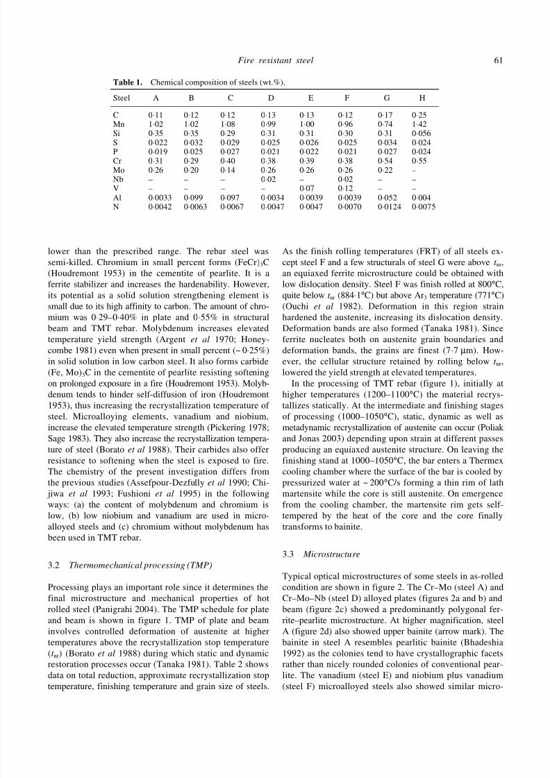
lity. The chemical composition of steels is given in table 1.
The carbon was 0⋅11–0⋅13% in plate, 0⋅17% in structural
beam and 0⋅25% in TMT rebar. The conventional way to
improve moderately the strength at elevated temperature
(up to ~ 350°C) is by increasing the carbon content (Houdre-
mont 1953). Lower carbon in hot-rolled steel improves
notch toughness and weldability. In TMT rebar carbon
increases the hardenability. Manganese increases the strength
by solid solution hardening (Baird and Jamieson 1972) in
hot rolled steel. Manganese tends to lower the eutectoid
carbon content in steel and promotes segregation particu-larly in hot rolled structural steel with carbon > 0⋅10%.
This can adversely affect the mechanical properties. Manga-
nese was restricted to 1% in fire resistant hot rolled plate
and structural with carbon 0⋅10–0⋅20% and 1⋅5% in TMT
rebar where manganese is a potential hardenability en-
hancing element. Silicon content in steels A–G varied
from 0⋅29–0⋅35%. Silicon is a solid solution strengthener
and a deoxidizer. Silicon retards softening at high tem-
peratures (Irvine 1962) and also increases the hardenability.
However, in steel H, its content was low due to tech-
noeconomic reasons. The aluminium (0⋅01–0⋅02%) is
required to tie-up free nitrogen to improve toughness. In
the steels A, D, E and F, the content of aluminium was
7/30/2019 Fire Resistance in Steel
http://slidepdf.com/reader/full/fire-resistance-in-steel 3/8
Fire resistant steel 61
Table 1. Chemical composition of steels (wt.%).
Steel A B C D E F G H
C 0⋅11 0⋅12 0⋅12 0⋅13 0⋅13 0⋅12 0⋅17 0⋅25Mn 1⋅02 1⋅02 1⋅08 0⋅99 1⋅00 0⋅96 0⋅74 1⋅42
Si 0⋅35 0⋅35 0⋅29 0⋅31 0⋅31 0⋅30 0⋅31 0⋅056S 0⋅022 0⋅032 0⋅029 0⋅025 0⋅026 0⋅025 0⋅034 0⋅024P 0⋅019 0⋅025 0⋅027 0⋅021 0⋅022 0⋅021 0⋅027 0⋅024Cr 0⋅31 0⋅29 0⋅40 0⋅38 0⋅39 0⋅38 0⋅54 0⋅55Mo 0⋅26 0⋅20 0⋅14 0⋅26 0⋅26 0⋅26 0⋅22 –Nb – – – 0⋅02 – 0⋅02 – –V – – – – 0⋅07 0⋅12 – –Al 0⋅0033 0⋅099 0⋅097 0⋅0034 0⋅0039 0⋅0039 0⋅052 0⋅004N 0⋅0042 0⋅0063 0⋅0067 0⋅0047 0⋅0047 0⋅0070 0⋅0124 0⋅0075
lower than the prescribed range. The rebar steel was
semi-killed. Chromium in small percent forms (FeCr)3C
(Houdremont 1953) in the cementite of pearlite. It is aferrite stabilizer and increases the hardenability. However,
its potential as a solid solution strengthening element is
small due to its high affinity to carbon. The amount of chro-
mium was 0⋅29–0⋅40% in plate and 0⋅55% in structural
beam and TMT rebar. Molybdenum increases elevated
temperature yield strength (Argent et al 1970; Honey-
combe 1981) even when present in small percent (~ 0⋅25%)
in solid solution in low carbon steel. It also forms carbide
(Fe, Mo)3C in the cementite of pearlite resisting softening
on prolonged exposure in a fire (Houdremont 1953). Molyb-
denum tends to hinder self-diffusion of iron (Houdremont
1953), thus increasing the recrystallization temperature of steel. Microalloying elements, vanadium and niobium,
increase the elevated temperature strength (Pickering 1978;
Sage 1983). They also increase the recrystallization tempera-
ture of steel (Borato et al 1988). Their carbides also offer
resistance to softening when the steel is exposed to fire.
The chemistry of the present investigation differs from
the previous studies (Assefpour-Dezfully et al 1990; Chi-
jiwa et al 1993; Fushioni et al 1995) in the following
ways: (a) the content of molybdenum and chromium is
low, (b) low niobium and vanadium are used in micro-
alloyed steels and (c) chromium without molybdenum has
been used in TMT rebar.
3.2 Thermomechanical processing (TMP)
Processing plays an important role since it determines the
final microstructure and mechanical properties of hot
rolled steel (Panigrahi 2004). The TMP schedule for plate
and beam is shown in figure 1. TMP of plate and beam
involves controlled deformation of austenite at higher
temperatures above the recrystallization stop temperature
(t nr) (Borato et al 1988) during which static and dynamic
restoration processes occur (Tanaka 1981). Table 2 shows
data on total reduction, approximate recrystallization stop
temperature, finishing temperature and grain size of steels.
As the finish rolling temperatures (FRT) of all steels ex-
cept steel F and a few structurals of steel G were above t nr,
an equiaxed ferrite microstructure could be obtained withlow dislocation density. Steel F was finish rolled at 800°C,
quite below t nr (884⋅1°C) but above Ar3 temperature (771°C)
(Ouchi et al 1982). Deformation in this region strain
hardened the austenite, increasing its dislocation density.
Deformation bands are also formed (Tanaka 1981). Since
ferrite nucleates both on austenite grain boundaries and
deformation bands, the grains are finest (7⋅7 µm). How-
ever, the cellular structure retained by rolling below t nr,
lowered the yield strength at elevated temperatures.
In the processing of TMT rebar (figure 1), initially at
higher temperatures (1200–1100°C) the material recrys-
tallizes statically. At the intermediate and finishing stagesof processing (1000–1050°C), static, dynamic as well as
metadynamic recrystallization of austenite can occur (Poliak
and Jonas 2003) depending upon strain at different passes
producing an equiaxed austenite structure. On leaving the
finishing stand at 1000–1050°C, the bar enters a Thermex
cooling chamber where the surface of the bar is cooled by
pressurized water at ~ 200°C/s forming a thin rim of lath
martensite while the core is still austenite. On emergence
from the cooling chamber, the martensite rim gets self-
tempered by the heat of the core and the core finally
transforms to bainite.
3.3 Microstructure
Typical optical microstructures of some steels in as-rolled
condition are shown in figure 2. The Cr–Mo (steel A) and
Cr–Mo–Nb (steel D) alloyed plates (figures 2a and b) and
beam (figure 2c) showed a predominantly polygonal fer-
rite–pearlite microstructure. At higher magnification, steel
A (figure 2d) also showed upper bainite (arrow mark). The
bainite in steel A resembles pearlitic bainite (Bhadeshia
1992) as the colonies tend to have crystallographic facets
rather than nicely rounded colonies of conventional pear-
lite. The vanadium (steel E) and niobium plus vanadium
(steel F) microalloyed steels also showed similar micro-

7/30/2019 Fire Resistance in Steel
http://slidepdf.com/reader/full/fire-resistance-in-steel 4/8
Bimal Kumar Panigrahi62
Figure 1. Schematic of TMP schedule for plate, beam and TMT rebar (M, martensite; γ , austenite).
Figure 2. As hot rolled microstructures of a. Cr–Mo plate (steel A), b. Cr–Mo–Nb plate(steel D), c. Cr–Mo beam (steel G) and d. pearlitic bainite of Cr–Mo plate (steel A).
Table 2. Process parameters and microstructural data.
Thickness Total FRT Grain sizeSteels (mm) reduction (%) t nr (°C) (°C) Structure (µm) Product
A 14 86 814⋅0 900 F + P + B 10⋅4 PlateB 12 88 853⋅5 900 F + P 13⋅5 PlateC 12 88 874⋅3 900 F + P 12⋅5 PlateD 12 88 876⋅9 900 F + P + B 11⋅0 PlateE 12 88 828⋅5 875 F + P + B 12⋅5 PlateF 12 88 884⋅1 800 F + P + B 7⋅7 PlateG – 94* 874 850–925 F + P + B 10⋅3 BeamH – 92 984⋅4 1000 M + B – Rebar
F, Ferrite; P, pearlite; B, bainite; M, tempered martensite; *flange region; t nr
= 887 +464%C + (6645%Nb−664√%Nb) + (732%V−230√%V) + 890% Ti + 363%Al−357%Si.

7/30/2019 Fire Resistance in Steel
http://slidepdf.com/reader/full/fire-resistance-in-steel 5/8
Fire resistant steel 63
Figure 3. Bright field TEM of a. Cr–Mo–Nb–V plate (steel F), b. and c. Cr–Mo beam (steel G) and d. TMT rebar.
structures. The bainite ‘colonies’ in steel G were coarser
than steels A, D, E and F and were more numerous possi-
bly due to presence of somewhat higher carbon and
chromium in this steel, lower reduction per pass andcoarser austenite grains prior to transformation. The bainite
was not observed in steels B and C. The finishing rolling
in the austenite region above recrystallization stop tempera-
ture helped to form polygonal ferrite grain structure in
Cr–Mo, Cr–Mo–Nb and Cr–Mo–V plate steels. In this
case ferrite nucleates on austenite grain boundaries (Tanaka
1981). Cr–Mo–Nb–V plate (steel F) was finish rolled in
the unrecrystallized austenite region producing grain size
finer than other steels (table 2) due to nucleation of ferrite
on austenite grain boundaries, transgranular twins and
deformation bands (DeArdo 1995; Panigrahi 2001) after
transformation. The partial cellular structure of steel Fwith dislocations retained is shown in figure 3a. The beam
steel also showed upper bainite (figure 3b) with cementite
particles distributed between ferrite platelets (figure 3c).
An exposure treatment up to 3 h at 600°C did not show
changes in the appearance of microstructure. Unlike
martensite in which dissolved carbon in solid solution is
high, bainite has little carbon in solid solution and is
much less sensitive to tempering at low temperatures
(~ 600°C). However, cementite particles can coarsen and
a general recovery of dislocation substructure occurs
(Bhadeshia 1992). The TMT rebar steel showed a tempered
martensite rim. The core structure was bainitic (figure 3d)
due to high hardenability of this steel.
3.4 Elevated temperature yield stress
The dependence of yield stress and UTS with temperature
for steels A–G is shown in figure 4. Steel F showed afaster drop of yield stress after 500°C. However, except
steel C (0⋅14%Mo) whose yield stress was marginally
below the desired level at 600°C, all other steels retained
two-thirds of their room temperature yield strength at
600°C (table 3). The elevated temperature yield stress de-
pends mainly on the stability of microstructure at higher
temperatures. Chromium and molybdenum have a stabi-
lizing effect on cementite of pearlite (Houdremont 1953).
A higher amount of chromium in steel C prevented exce-
ssive drop of yield stress at 600°C despite low molybdenum
(0⋅14%) in it. Steels D and E that are microalloyed with
Nb and V, respectively have highest level of yield stressat 600°C viz. 82% and 85%, respectively. Nb and V have
added advantages due to their precipitation hardening
potential and the loss of strength at higher temperature is
minimal. The rapid drop of yield stress of steel F above
500°C was due to lowering of dislocation density on
soaking above 500°C. The UTS of all steels fell sharply
above 400°C (figure 4). The elongation of all steels at
600°C was higher than elongation at the ambient tem-
perature. Exposure at 600°C for 3 h increased the yield
stress by about 50 MPa without significant change in
elongation in steels A, D, E, F and G. The core of rebar steel
H with bainitic structure also showed two-thirds of room
temperature yield stress at 600°C (table 3). Due to presence of

7/30/2019 Fire Resistance in Steel
http://slidepdf.com/reader/full/fire-resistance-in-steel 6/8
Bimal Kumar Panigrahi64
Figure 4. Dependence of (a) yield stress and (b) UTS on temperatures of fire resistant steels and mild steel (MS).
Table 3. Tensile properties of the investigated steels.
Steel A B C D E F G H
Ambient temperature (RT)YS (MPa) 287 293 298 338 293 415 320 624UTS (MPa) 505 486 539 582 530 622 541 819El. (%) 38⋅0 36⋅2 32⋅0 30⋅0 37⋅8 26⋅8 27⋅3 12⋅5
Elevated temperature (600°C)YS (MPa) 219 191 188 279 250 280 214 419UTS (MPa) 326 259 247 332 327 338 292 426El. (%) 42⋅2 41⋅7 49⋅0 40⋅4 36⋅2 46⋅0 33⋅0 30⋅5% of room temperature YS 76⋅3 65⋅1 63⋅0 82⋅5 85⋅3 67⋅4 66⋅8 67⋅1
After thermal exposure at 600°C under applied stressYS (MPa) 360 – – 408 348 469 369 –UTS (MPa) 432 – – 523 475 584 492 –El. (%) 22⋅5 – – 30⋅8 34⋅0 22⋅8 27⋅0 –
tempered martensite rim, the overall strength of TMT
rebar at 600°C should be higher than two-thirds of its
room temperature yield strength. In a composite micro-
structure comprising tempered martensite rim and bainitic
core, the overall yield stress is given by area fraction of
rim multiplied by yield stress of rim plus area fraction of
core multiplied by yield stress of core. The area fraction
of bainite core was 0⋅766 and that of tempered martensite
rim was 0⋅234. Previous investigation (Panigrahi 2002)
showed that low-alloyed tempered martensite structure
had more than two-thirds of room temperature yield
stress at 600°C.
3.5 Impact toughness
The ambient temperature impact toughness, 50% energy
ductile brittle transition temperature (DBTT) (Dahl 1992)
and fracture characteristics are given in table 4. The upper
shelf energy of as-rolled plate and beam varied from 65–
118 J (figure 5). The steels A, D, E and F showed DBTT
at – 4°C to –12°C. The DBTT of steel B was below –30°Cand that of steel C was –28°C. Presence of upper bainite
in all steels except steels B and C, low aluminium content
(steels A, D, E and F) and cellular structure (steel F)
were responsible for increase in DBTT. Notwithstanding
Temperature (°C)Temperature (°C)

7/30/2019 Fire Resistance in Steel
http://slidepdf.com/reader/full/fire-resistance-in-steel 7/8
Fire resistant steel 65
higher carbon content, steel H showed a DBTT of –14°Cdue to presence of tempered martensite and some acicular
ferrite in it. Steel G showed a DBTT of –5°C in as rolled
condition and –34°C in aged condition. The DBTT of
steel G in as rolled condition was higher than steel A possibly
due to presence of relatively coarser ‘colonies’ of pearliticbainite in its microstructure and a higher carbon content
(0⋅17%) (Pickering 1978) compared to steel A (0⋅11%
Figure 5. Charpy energy vs temperature curves of plates andbeam.
Figure 6. Typical time–temperature curves for Cr–Mo beam(steel G) and mild steel (T1, T2 and T3 are locations of thermo-
couples at section 1).
carbon). On exposure at 600°C, the improved toughness
(DBTT: –34°C) of steel G could be due to lowering of
dislocation density of bainite and diffusion of embrittling
atoms present on the grain boundaries to the dislocations.
Improvement of impact transition temperature by diffusion
of phosphorus from prior austenite grain boundaries tolattice defects was reported earlier for spring steel (Wettlaufer
and Kasper 2000). However, upper shelf energy of aged
steel was lower than the as-rolled beam possibly due to
microstructural heterogeneity leading to formation of local-
ized carbide rich areas that aided lowering of the absorbed
energy.
3.6 Fire resistance
The average temperature rise of fire resistant steel (FRS)
beam and mild steel (MS) beam (0⋅17C, 0⋅69Mn, 0⋅04Si,0⋅048S, 0⋅028P, 0⋅007Al) is shown in figure 6 for section
Table 4. Charpy toughness data.
Toughness at RT DBTT FractureSteel (Joule) (°C) surface at RT
A 118 − 12 DimpleB 116 <− 30 DimpleC 100 − 28 DimpleD 94 − 9 DimpleE 82 − 8 DimpleF 73 − 4 Dimple
G (as rolled) 87 −
5 DimpleG (after thermal exposure 50 − 34 Dimple
at 600°C)H 88 − 14 Quasi cleavage
Note: All values of toughness are for full size specimens.
Figure 7. Dependence of thermal conductivity of dilute steel
alloys on temperatures.
Temperature (°C)
T e m p e r a t u r e
( ° C )
Temperature (°C)

7/30/2019 Fire Resistance in Steel
http://slidepdf.com/reader/full/fire-resistance-in-steel 8/8
Bimal Kumar Panigrahi66
1 (inset). The rise of temperatures up to 600°C for other
sections was similar to section 1. It was observed that the
temperature of the fire resistant steel was at a lower level
compared to mild steel. The data points for these curves
remain below the ASTM E 119 standard time–temperature
curve in a fire test (ASTM 1996). The time to reach thecritical temperature (538°C) was 32 min and 21 min for
fire resistant steel and mild steel, respectively. The rate of
heating is dependent on the thermal conductivity which is
a material property governing the flow of heat through a
material at steady state. Figure 7 shows the dependence
of thermal conductivity with temperature for pure iron
and some constructional steels (Riemann 1953; McGannon
1966). The thermal conductivity of pure iron and dilute
alloys decreases with rising temperature. The likely be-
haviour of 0⋅5Cr–0⋅22Mo fire resistant steel which is a
dilute alloy is also shown in this figure. Its conductivity
should be higher than 30 W/m⋅k at 600°C. The dominantcarrier of the thermal conduction in pure metals and dilute
alloys is electrons (Ho et al 1975; Isachenko et al 1980;
Touloukian and Ho 1981; Landolt 1991). When small
amount of alloying elements (impurities) are introduced
in iron, it causes discontinuities in the crystal lattice struc-
ture and promotes scattering of free electrons decreasing
the room temperature thermal conductivity (Riemann 1953;
McGannon 1966). With rising temperature, the scattering
of free electrons is intensified (Isachenko et al 1980). This
causes a net reduction of thermal conductivity at higher
temperature. Even then the thermal conductivity of dilute
steel alloy is still high (> 30 W/m⋅k) at 600°C. Since in a
fire, temperature gradients are encountered, a high ther-
mal conductivity material is desired to avoid degradation
by local necking.
4. Conclusions
Small additions of Mo (0⋅20–0⋅25%) and Cr (0⋅30–0⋅55%)
in low carbon steel produced hot rolled fire resistant steel
with a minimum of two-thirds of room temperature yield
stress at 600°C. Microalloying by niobium and vanadium
improved the ratio of YS600°C /YS RT . However, final rolling
temperature should be maintained in the recrystallized
austenite region to ensure a microstructure free from high
dislocation density. The steels should be adequately treated
by aluminium to tie-up free nitrogen in order to realize
lower DBTT. In the quenched and self-tempered TMT
rebar steel, addition of ~ 0⋅55% chromium was adequate
to ensure the guaranteed strength at 600°C due to transforma-
tion to tempered martensite rim and bainitic core. Despite
decreasing trend of thermal conductivity with the rise of
temperature in dilute alloys, the low alloy fire resistant
steel will have higher thermal conductivity up to 600°C(> 30 W/m⋅k) compared to more concentrated alloys and
is less expensive.
References
American Society of Testing Materials 1996 Standard test
methods for fire tests of building construction and materials ,
Philadelphia, E119
Argent B B, Niekenk M N and Redfern G A 1970 J. Iron &Steel Inst . 208 830
Assefpour-Dezfully M, Hugas B A and Brownrigg A 1990 Mater.
Sci. & Technol. 6 1210
Baird J D and Jamieson A 1972 J. Iron & Steel Inst . 210 847
Bhadeshia H K D H 1992 Bainite in steels (London: Institute of
Materials)
Borato F, Barbosa R, Yue S and Jonas J J 1988 Proc. Thermec’88
(ed.) I Tamura (Tokyo: Iron and Steel Inst. Japan) p. 388
Bureau of Indian Standards 1998 Indian Standards IS 2062,
New Delhi
Bureau of Indian Standards 2002 Indian Standards IS 15103,
New Delhi
Chijiwa R, Tamehiro H, Yoshida Y, Funato K, Uemori R and
Horii Y 1993 Nippon Steel Tech. Report 58 47
Dahl W 1992 Steel (Dusseldorf: Springer Verlag and Verlag
Stahl Eisen) 1
DeArdo A J 1995 Microalloying’95 (Warrendale: Iron and Steel
Society) p. 15
Fushioni M, Chikaraishi H and Keira K 1995 Nippon Steel Tech
Report 66 29
Ho C Y, Powell R W and Liley P E 1975 Thermal conductivity
of the elements: A comprehensive review (NewYork: AIP)
Honeycombe R W K 1981 Steel microstructure and properties
(London: Edward Arnold; Ohio : ASM)
Houdremont E 1953 Handbook of special steels (Berlin:
Springer Verlag) 1
Irvine K J 1962 J. Iron & Steel Inst . 200 820Isachenko V P, Osipova V A and Sukomel A S 1980 Heat
transfer (Moscow: Mir Publisher)
Landolt B 1991 Thermal conductivity of pure metals and alloys
(eds) O Madelun and G K White (Berlin: Springer Verlag)
15C
McGannon H E (ed.) 1966 Making, shaping and treating of
steels (Pittsburgh : USS)
Ouchi C, Sampei T and Kozasu I 1982 Iron & Steel Inst., Japan
22 214
Panigrahi B K 2001 Bull. Mater. Sci. 24 361
Panigrahi B K 2002 Unpublished result
Panigrahi B K 2004 Seminar on Structural steel for construction
industry (NIT, Rourkela: The Institution of Engineers)
Panigrahi B K and Jain S K 2002 Bull. Mater. Sci. 25 319
Pickering F B 1978 Physical metallurgy and design of steels
(London: Applied Science Pub.)
Poliak E I and Jonas J J 2003 Iron & Steel Inst. Japan Int . 43
692
Riemann W 1953 Stahl und Eisen 73 721
Sage A M 1983 Proc. int. conf. steels for line pipe and pipe line
fittings (London: Metals Soc.) p. 39
Tanaka T 1981 Int. Metal. Rev. 26 185
Touloukian Y S and Ho C Y 1981 Properties of selected fer-
rous alloying elements (New York: McGraw Hill Book Co.)
III.1
Wettlaufer M and Kasper R 2000 Steel Res. 71 357