final report far-infrared heterodyne ... report nasa grant nag 2-1062 far-infrared heterodyne...
TRANSCRIPT
FINAL REPORT
NASA GRANT NAG 2-1062
FAR-INFRARED HETERODYNE SPECTROMETER FOR SOFIA
Period: April I, 1996 through December 31, 1998
A. L. Betz, Principal Investigator
Center for Astrophysics & Space Astronomy,
University of Colorado, Boulder, CO 80309
ABSTRACT
This report summarizes work done under NASA Grant NAG2-1062 awarded to the
University of Colorado. The project goal was to evaluate the scientific capabilities and
technical requirements for a far-infrared heterodyne spectrometer suitable for the SOFIA
Airborne Observatory, which is now being developed by NASA under contract to the
Universities Space Research Association (USRA). The conclusions detailed below
include our specific recommendations for astronomical observations, as well as our
intended technical approach for reaching these scientific goals. These conclusions were
presented to USRA in the form of a proposal to build this instrument. USRA subse-
quently awarded the Univerisity of Colorado a 3-year grant (USRA 8500-98-010) to
develop the proposed Hot-Electron micro-Bolometer (HEB) mixer concept for high fre-
quencies above 3 THz, as well as other semiconductor mixer technologies suitable forhigh sensitivity receivers in the 2-6 THz frequency band.
JUL o 1 1999
A
-I-
https://ntrs.nasa.gov/search.jsp?R=20000005007 2018-06-13T16:35:23+00:00Z
Q 2
FINAL REPORT - NASA Grant NAG 2-1062
A Far-Infrared Heterodyne Spectrometer for SOFIA
A. L. Betz and R. T. Boreiko
Center for Astrophysics and Space Astronomy, University of Colorado, Boulder, CO 80309
1. Introduction
This final report for NASA Grant NAG 2-1062 "A Far-Infrared Heterodyne
Spectrometer for SOFIA" describes work performed during the original 9-month grant
period from 4-01-96 to 12-31-96, plus no-cost extension periods ending 12-31-98. The
project was a design study to optimize the design of a far-infrared heterodyne spectrometer
for the 50-300 #m spectral region that could eventually be used on the SOFIA Observatory.
As part of the design study, we investigated two mixer technologies for far-infrared detection
: quasioptical hot-electron microbolometers and Ga:Ge blocked-impurity band photomixers,
as well as three possible local oscillator solutions not previously used successfully for
infrared astronomy: cascaded multipliers, laser beat frequency synthesis, and laser sideband
generation.
The final instrument design is reported here along with discussions of the comparative
technologies that were examined. This discussion is preceded, however, by a summary of the
particular science investigations in astronomy which motivate the effort. The main result
from the project was a refined instrument proposal that was submitted to USRA, the prime
contractor to NASA for the SOFIA project. USRA subsequently awarded us a detector
development grant (USRA 8500-98-010) to extend the work on HEB mixers described here.
The spectrometer is ideally suited for observations of interstellar gas in regions of
moderate and high excitation, especially the cores of interstellar clouds where UV- and
shock-excitation are available. A sensitivity approaching the quantum noise limit and the
high spectral resolution of a heterodyne receiver, combined with SOFIA's large aperture,
will provide an observational facility unparalleled by any existing or planned space mission
for far-infrared astronomical spectroscopy. The following report describes the science we
want to do and how we intend to do it. The instrument is a dual band spectrometer with
a sensitivity better than 10 hu per unit bandwidth. This far-infrared sensitivity compares
favorably with the current state-of-the-art of 4 hu sensitivity for heterodyne spectrometers
at submillimeter and mid-infrared wavelengths. Our SOFIA spectrometer will have a
resolving power exceeding 106 and be able to observe 2 or more lines simultaneously with
3000 spectral channels of 0.3 km s -1 resolution. The new instrument is a second generation
version of the heterodyne spectrometer we used successfully on the KAO for 11 years
Q i 3 --
(Boreiko & Betz 1995). The advantages (and disadvantages) of the new design are discussed
in light of other observational capabilities planned for the wavelength region of interest:
50-200 #m. Items which may be called "new technology" are specifically identified, and the
rewards and risks associated with their development are discussed.
Heterodyne spectroscopy is the most practical and sensitive method for achieving
1 km s -1 resolution at far-infrared wavelengths. This resolution is required to make full
use of the information on dynamics available from the shapes and positions of spectral line
profiles. The advantages and capabilities of the technique have been amply demonstrated
with the first generation spectrometer flown aboard the KAO for over 10 years. The second
generation instrument described here will not only take full advantage of the superior spatial
resolution available from SOFIA, but also make efficient use of flight time by undertaking
multiple simultaneous observations with near quantum-noise-limited sensitivity. Although
the technical goals seem ambitious compared to current capabilities, recent breakthroughs
in HEB mixer technology make the effort actually easier than it may at first appear.
The report is divided into 3 areas: selected scientific goals, final instrument design, and
operational issues for the instrument onboard NASA's SOFIA Airborne Observatory. The
work was done by the P.I. Albert Betz, Betz, the co-I Rita Boreiko, together with postdoc
Philip Duggan and graduate student Yong-xin Luo.
2. Scientific Program: Star Formation and Astrochemistry
Star formation and the physical processes underlying its initiation are a key research
theme for the instrument. Information on this fundamental process can be gathered by
observing far-infrared radiation emanating from the dense cores of molecular clouds - the
so-called "stellar nurseries". These regions are typically 5-15" in size, and a telescope
aperture of 2-3 m is needed for the diffraction limit field of view (FOV) to be comparable
in angular size. Measurements of temperature, density, composition, and dynamics can all
be made by observing spectral line radiation from atomic and molecular gas within these
cores. Gas temperatures in star formation regions are typically in the range of 30-100 K.
At such temperatures the peak of the blackbody curve falls at far-infrared wavelengths and
line emission is strongest between 30-100 #m if the gas is in thermal equilibrium. Ideally,
observations of line emission should be done with a spectral resolution adequate to identify
the various cloud components by means of their differing Doppler shifts. In addition,
measurements of the shapes of individual line profiles provide further discrimination
between quies_.nt and shock-excited gas. All sorts of dynamical effects (outflows, infalls,
shocks, jets, "and rotation) can be measured by instruments with good spectral and spatial
resolution. The required spectral resolution is governed by the widths of the narrowest
features, which are about 1 km s -1. A resolving power of 106 is consequently necessary, if
it can be obtained without compromise in sensitivity.
i -- 4 --
Not all line emission is so narrow, of course. Shock excitation can produce line widths
exceeding 100 km s -1 (FWZM), and so a wide observing bandwidth of 4 GHz (400 km s -I
at 3 THz) is also important. Fortunately the technology of the 1990's is up to the challenge,
and it is now possible to do "radio astronomy" up to 6 THz (50 #m).
Because the core regions are so small, close to the diffraction limit of SOFIA in the
far-infrared, extensive spatial mapping is not usually required, although for certain complex
sources it would be desirable. Hence, in designing the instrument we stress spectral
resolution over total spatial FOV. Other planned instruments with lower spectral resolution
but with large array detectors are more appropriate for large scale mapping. Large scale
mapping can also be done with smaller telescopes than SOFIA (if such were available).
Nevertheless, we will design in a small array capability (6-8 elements) for our spectrometer
to enable limited but perhaps adequate "imaging" of core regions. Arrays beyond this
size become difficult for us to use from a data handling point of view. Remember each
spatial element requires a multichannel "back-end" to analyze the line radiation. Radio
telescopes currently use small 8-10 element arrays in the focal plane, and find the data rate
manageable. We do not anticipate actually installing spatial arrays in the spectrometer
until after the second year of flights with the multiband spectrometer.
Heterodyne spectroscopy offers the potential to achieve the Doppler-limited resolution
we require together with the high sensitivity we also must have. Theoretically, a heterodyne
receiver can achieve a sensitivity of r/-I photons per second per unit bandwidth: Pnoise/B --
v/r/, where 77is the effective quantum efficiency. This is the so-called quantum-noise-limit
for receivers using coherent detection. The established technology of GaAs Schottky diode
mixers at best achieves 77= 1% at far-infrared wavelengths (Betz & Boreiko 1993), so there
is considerable room for improvement. The factor of 10 increase in sensitivity with HEB
mixers compared to Schottky diodes, plus the larger aperture of SOFIA compared to the
KAO, will speed line detections in small sources (e.g., cloud cores and stellar sources) by a
factor of 104 . Entirely new problems can now be investigated on SOFIA that would never
have been considered in the days of the KAO.
2.1. The Value of Resolution
We can simplistically classify all observations into two groups based on the ultimate
signal-to-noise ratio of the measurement: (1) High signal-to-noise observations are those
which are easily done but must be done repeatedly, for example mapping line emission
or observing a-large variety of sources in order to measure some global property of the
emission. It has been our experience on the KAO that such observations are popular with
GI teams, who need KAO observations to complement existing radio- or near-IR data.
Examples would be observations of high-J CO, C II, and O I - all major cooling lines for
warm molecular clouds. (2) Low signal-to-noise observations usually deal with the detection
-- 5
of a weak line in a small number of sources,with the intent being speciesidentificationor an isotopic ratio measurement. In such observations,high resolution is essentialforunambiguousline identification.
To illustrate the added insight one can get by re-examiningpreviously detected lineemissionat higher spectral resolution, wepresent two examplesfrom the KAO: high-J CO
and OH rotational emission.
2.1.1. High-J CO Emission
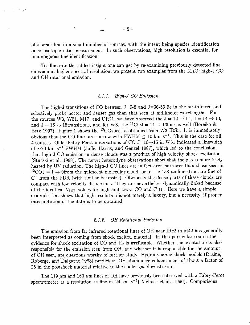
The high-J transitions of CO between J=9-8 and J=36-35 lie in the far-infrared and
selectively probe hotter and denser gas than that seen at millimeter wavelengths. For
the sources W3, W51, M17, and DR21, we have observed the J = 12 _ 11, J = 14 --+ 13,
and J = 16 _ 15transitions, and for W3, the 13COJ = 14 -_ 13line as well (Boreiko &
Betz 1997). Figure 1 shows the 13COspectra obtained from W3 IRS5. It is immediately
obvious that the CO lines are narrow with FWHM < 10 km s -1. This is the case for all
4 sources. Older Fabry-Perot observations of CO J=16--+15 in W51 indicated a linewidth
of _70 km s -1 FWHM (Jaffe, Harris, and Genzel 1987), which led to the conclusion
that high-J CO emission in dense clouds was a product of high velocity shock excitation
(Stutzki et al. 1988). The newer heterodyne observations show that the gas is more likely
heated by UV radiation. The high-J CO lines are in fact even narrower than those seen in
12COJ = 1 --+ 0from the quiescent molecular cloud, or in the 158 #mfine-structure line of
C + from the PDR (with similar beamsize). Obviously the dense parts of these clouds are
compact with low velocity dispersions. They are nevertheless dynamically linked because
of the identical VLSR values for high and low-J CO and C II . Here we have a simple
example that shows that high resolution is not merely a luxury, but a necessity, if proper
interpretation of the data is to be obtained.
2.1.2. OH Rotational Emission
The emission from far infrared rotational lines of OH near IRc2 in M42 has generally
been interpreted as coming from shock excited material. In this particular source the
evidence for shock excitation of CO and H2 is irrefutable. Whether this excitation is also
responsible for the emission seen from OH, and whether it is responsible for the amount
of OH seen, are questions worthy of further study. Hydrodynamic shock models (Draine,
Roberge, and Dalgarno 1983) predict an OH abundance enhancement of about a factor of
25 in the postshock material relative to the cooler gas downstream.
The 119 #m and 163 #m lines of OH have previously been observed with a Fabry-Perot
spectrometer at a resolution as fine as 24 km s-l( Melnick et al. 1990). Comparisons
Q -- 6 --
10
5
0
10
_-
5
i • i , i
-60 -40 -20VLSR (km sI)
Fig. 1.-- 12CO J = 12 --+ 11, J = 14 --+ 13, and J = 16 --+ 15 spectra obtained at W3 IRS5.
between intensities suggested to these authors that the ground state 119 #m transition was
too weak for a single component model to be applicable. Various additional complexities
were suggested; none of which completely solved the anomaly. In 1989 we observed
the 119 #m line with our heterodyne spectrometer on the KAO (Betz & Boreiko 1989).
Measurements at 0.6 km s-_ resolution clearly showed that the blue-side of the 119 #m
emission was completely missing, and probably self-absorbed by subthermally excited OH in
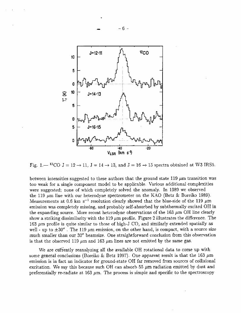
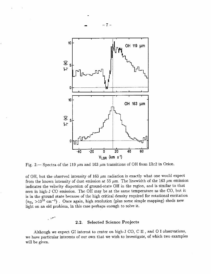
the expanding source. More recent heterodyne observations of the 163 #m OH line clearly
show a striking dissimilarity with the 119 #m profile. Figure 2 illustrates the difference. The
163 #m profile is quite similar to those of high-J CO, and similarly extended spatially as
well - up to +30". The 119 #m emission, on the other hand, is compact, with a source size
much smaller than our 30" beamsize. One straightforward conclusion from this observation
is that the observed 119 #m and 163 #m lines are not emitted by the same gas.
We are cu_ently reanalyzing all the available OH rotational data to come up with
some general conclusions (Boreiko & Betz 1997). One apparent result is that the 163 #m
emission is in fact an indicator for ground-state OH far removed from sources of collisional
excitation. We say this because such OH can absorb 55 #m radiation emitted by dust and
preferentially re-radiate at 163 #m. The process is simple and specific to the spectroscopy
.- 7
10
A
"-'5
°I i....................;...............;
i i !
10
; i I i
....:. ..........................................
; I I I ,
• i i i
OH 163 p,rn
_5i-"
0 --
I I I ; I I I
-40 -20 0 20 40 60
VLS R (km s-1)
Fig. 2.-- Spectra of the 119 #m and 163 pm transitions of OH from IRc2 in Orion.
of OH, but the observed intensity of 163 #m radiation is exactly what one would expect
from the known intensity of dust emission at 55 #m. The linewidth of the 163 #m emission
indicates the velocity dispersion of ground-state OH in the region, and is similar to that
seen in high-J CO emission. The OH may be at the same temperature as the CO, but it
is in the ground state because of the high critical density required for rotational excitation
(nil2 >101° cm -3) • Once again, high resolution (plus some simple mapping) sheds new
light on an old problem, in this case perhaps enough to solve it.
2.2. Selected Science Projects
Although we expect GI interest to center on high-J CO, C II, and O I observations,
we have particular interests of our own that we wish to investigate, of which two examples
will be given.
"_ --8--
2.2.1. The 12C//13C Isotopic Ratio
The 12C/13C isotopic ratio of the interstellar medium is believed to be one of the most
important parameters for tracing the chemical evolution of the galaxy. 12C is a primary
product of stellar nucleosynthesis because it can be formed in first generation, metal-poor
stars, while 13C is a secondary product. Thus, for successive cycles of star formation and
enrichment of the interstellar medium with processed material, the 12C/13C ratio is expected
to decrease with time, eventually reaching a steady-state value near 4. The solar system
value of ,,_89 is thought to be representative of the interstellar medium approximately 5
billion years ago, while the present ratio can serve as a useful check on models of galactic
evolution.
The _2C/13C ratio can be measured from the relative intensities of molecular lines,
such as CO, but the estimates are subject to uncertainty because of the effects of chemical
fractionation, self-shielding from photodissociation, and line saturation of the more
abundant isotopomer. Other observational effects, especially at millimeter wavelengths, are
uncertainties in calibration because the various sets of data are not all taken with the same
telescope pointing and receiver setting.
An excellent way of measuring the 12C/_3C ratio, at least in photodissociation regions,
is to observe the 158 ttm lines of 12C II and 13C II . The ratio can be obtained directly
from the relative intensities of the lines, as long as the stronger 12C II line is not optically
thick. In sources such as M42, however, the 12C II optical depth is on the order of unity,
and corresponding corrections must be made. The best way of estimating the 12C II optical
depth is to also measure the O I line at 63 #m. Emission from O I comes from the same
PDR gas as that from C II (approximately), and because of the significantly higher optical
depth of the O I line, it is an excellent indicator of temperature. Of course, in reality one
must also consider the possibility that the O I is subthermally excited, but this problem
can be handled, too. Once we know the gas kinetic temperature, we can estimate the 12C II
optical depth from its measured peak line intensity. Here we depend on the high resolution
of heterodyne spectroscopy, because we need to know the true peak 12C II intensity and the
line can be as narrow as 4 km s -1. We also must be able to separate the '2C II emission
from the 3 weaker 13C II emission lines, the strongest of which is only 11 km s-_away. This
procedure has been used effectively for M42, where we derived a 12C/13C ratio of 58, in
agreement with the value obtained from an empirical relationship between the isotopic ratio
and Galactocentric distance (Boreiko & Betz 1996).
It is our goal to measure the 12C/13C ratio in a variety of clouds within our Galaxy,and to extend the technique to nearby galaxie s such as the Magellanic Clouds. The small
beam size of SOFIA and the high sensitivity of the HEB mixers (to be described later) are
essential to this effort.
! -- 9 --
2.2.2. Hell + at 149 #m
Hell +, the product of the two most abundant elements in the universe, is the simplest
closed-shell heteronuclear molecule. Its existence in astrophysical environments has been
a subject of interest ever since the possibility was first suggested by Dabrowski and
Herzberg (1977). Later Roberge and Dalgarno (1982) extended several theoretical studieson the abundance of Hell + and concluded that emission in the J = 1 -4 0rotational line at
149.13 #m (2010 GHz) may be detectable from H II blisters on the peripheries of molecular
clouds. Any observation of this ion that allows its abundance to be measured would be
quite important for validating chemical modeling codes. Hell + , besides being significant
in its own right, is also an important intermediary in many basic reactions of ion-molecule
theories of molecular clouds. It also offers the intriguing possibility of being a direct
indicator of high intensity X-ray phenomena in accretion disks and other compact occluded
regions.
Emission by Hell + in Dense Molecular Clouds
Hell + is expected in dense clouds where X-ray or XUV photons are present. The
ionizing radiation produces vibrationally excited H + which reacts with He atoms to form
Hell +. Collisions with He are the dominant loss mechanism for Hell +. Roberge and
Dalgarno (1982) give a formula for the minimally expected flux in the 149 #m Hell + line
from a cloud where a stated number of H2 molecules s -1 are ionized. The estimate is
a lower limit because it assumes that the J=l rotational level is only populated by the
formation process. The O and OB associations which produce this ionization often appear
concentrated at the edges of dense clouds, where they can burn blister-like H II regions.
In such regions we might expect to see 149 #m emission. Their line flux formula gives an
estimate of 2 × 10 -11 ergs cm -2 s -1 at 149 #m from a source 0.5 kpc away (e.g., M42). With
the SOFIA telescope this flux produces an antenna temperature T_ of 14 K or more at the
center of a line 5 km s -1 wide, or half that for a 10 km s -1 wide line. These are strong lines
that can easily be detected with our spectrometer. Despite its intrinsic uncertainties, the
estimate underscores the feasibility of detecting Hell + in emission at 149 #m. Furthermore,
the total line flux could be higher, because the calculation neglects the effects of ionization
of H2 by helium recombination photons and the excitation of Hell + by collisions. On the
down side, although the minimum T* estimate assumes that the emitting source is several
times larger than the 15" beam, it could be larger. But increased flux could be available
from side-illuminated ionization fronts (blisters) seen edge-on.
Since our system noise temperature should be no worse than 2000 K (DSB) near 2010GHz, we can detect a 0.4 K line of 5 km s -_ linewidth at the 5 a level after a 20-minute
integration. A 7 or 14 K line is strong enough that details in the lineshape could be explored
for comparison with C II and high-J CO spectra taken at similar 0.5 km s -_ resolution.
If the theoretical predictions hold true, in a 1-hr flight leg we could also map an extended
region for comparison once again with other species found near PDR regions.
-- - 10-
If collisionsare infrequent enoughto maintain much population in the J=i level, itmay prove moreproductive to searchfor the 2010GHz line in absorption, suchas againstthe strong continuum of IRc2 in M42 or Sgr B2. This is the approach that led to thedetection of a line at the 1370GHz frequency of H2D+ (Boreiko and Betz 1993). To seeHell + in absorptionagainst a 4 K continuum, wewill needcolumn densitiesin the rangeof4 × 1012cm-2 to yield a 15%absorption over a 10km s-1 linewidth, similar to that seeninthe 1370GHz line. The integration time required for a 5 a detection of a 0.6 K absorptionline of 10 km s -1 linewidth is about 30 minutes.
Emission by Hell + in Gaseous Nebulae
In ionized nebulae Hell + is produced by a number of pathways such as radiative
association of He + with H, or H + with He, or by reactions of vibrationally excited H +
ions with He atoms. Conversely, Hell + is destroyed by dissociative recombination with
electrons, by photodissociation, and by reactions with either atomic or molecular hydrogen.
A theoretical paper by Cecchi-Pestellini and Dalgarno (1993) discusses the comprehensive
chemistry of Hell + in ionized nebulae in general and in the source NGC 7027 in particular.
Their calculations reaffirm the estimates of Roberge and Dalgarno (1982) that Hell +
abundances on the order of 1012 cm -2 can be expected in nebulae if the effective temperature
of the ionizing source exceeds 50,000 K. The intensity of the J = 1 --_ 0 line at 149 #m is
proportional to the path integral of the electron density ne and nHeH+, provided that ne is
not so large that the excited state is quenched (i.e., ne < 107 cm-3). For ne <10 s cm -3, the
Hell + molecules reside mostly in the J = 0 level.
Cecchi-Pestellini and Dalgarno (1993) predict specific intensities for the planetary
nebula NGC 7027, for which detailed models of the temperature and density structures are
available. For the 149 #m line they predict a flux of ,,_ 2 × 10 -12 ergs cm -2 s -1. With the
SOFIA telescope this flux produces an antenna temperature more than 1 K (depending on
source size) at the center of a line 10 km s -1 wide, which we can detect easily on one 30
minute flight leg.
One important observational problem with detecting Hell + is that a strong line
of atmospheric O3 falls 260 MHz (36 km s -1) below the frequency of the Hell + line.
Consequently, observations are best done when the source has a net blue shift. Another
potential problem, albeit only for lower resolution instruments, is that the Hell + line
frequency is close to those of several strong CH lines. Although ISO may have the
sensitivity to detect Hell + in some sources, it probably doesn't have the spectral resolution
to distinguish Hell + from CH. This is a good problem for SOFIA.
-11-
3. Justification for Airborne Observations
3.1. Observational Requirements
The 50-200 #m interval of the far-infrared spectrum is absorbed by atmospheric
water vapor which precludes groundbased observations, even from sites at the South Pole.
Although theoretically a 10-15% transmission at certain far-infrared wavelengths can be
obtained under ideal conditions at the South Pole, for practical astronomical purposes this
transmission is not useful. Far-infrared observations must necessarily be done above the
tropopause where the residual water in a vertical column is less than 15 #m precipitable.
Under these conditions most of the FIR spectrum is observationally accessible, aside from
the specific transition frequencies of water vapor, molecular oxygen, and ozone. The
improvement in atmospheric transmission with increasing altitude is as much a function
of reduced pressure broadening as reduced water abundance, because many water lines
are saturated. Far-infrared absorption by high altitude ozone cannot be mitigated by
observations at aircraft altitudes, but fortunately the ozone problem is not nearly so severe
as that from water vapor.
3.2. SOFIA's Spectroscopic Advantage
In planning a research program for a new instrument, it is important to take into
account existing observational facilities and those planned which may be competitive with
SOFIA for high resolution studies of star formation.
The big advantage of SOFIA over the KAO is simply its bigger size. The 3-fold
improvement in telescope aperture is particularly significant for observations of compact
regions, such as the cores of molecular clouds. Observations with ground-based
interferometers at millimeter wavelengths on a scale-size of a few arcsec are currently the
best way to study cloud cores. The 2.5 m aperture of SOFIA will produce a diffraction
limited beamsize of 8" at _ =100 #m, which puts it on approximately equal footing
(resolution wise) with mm wave interferometers and the largest ground-based submillimeter
telescopes. Because SOFIA can observe in the far-infrared, however, it alone will be able to
observe the dominant cooling lines of high-J CO, the most pervasive molecule other than
molecular hydrogen. No other observational facility, either existing or planned, has the
same combination of sensitivity, spatial and spectral resolution needed to study CO in star
formation regions in such detail.
Of all the i_fifrared facilities either in place or planned for space-based observations, only
SOFIA will have the capability to do high resolution spectroscopy over the entire far-infrared
spectral region from 50 to 200 #m. Conversely, because most space observatories will have
excellent imaging capabilities over large fields, it is also appropriate that SOFIA emphasize
high resolution spectroscopy to complement the imaging capabilities of space observatories
-- -12-
such as ISO, SIRTF, and FIRST. Similarly, becauseSOFIA hasa larger aperture thanISO or SIRTF (and perhapsno smaller than FIRST), it is also appropriate that SOFIAemphasizeobservationsrequiring high spatial resolution, such asthe aforementionedcloudcoresand protostellar regions.
For high resolution spectroscopySOFIA will be unmatched. ISO coversthe 45-190#mband, but only with a resolving powerof 10,000from a scanningFabry-Perot. Its beamsizeis also more than 4 times larger. IRTS hasa far-infrared line mapper instrument (FILM)for the 63 #m and 158 #m channels(O I and C II, respectively),but the resolving poweris only 400 and the FOV is 8x13'. SIRTF will only havea spectrophotometric capabilitybetween50 and 100 #m, with a resolving power of 20, and is not really suited for line
work in the far-infrared. SWAS will have approximately the spectral resolution of the our
SOFIA spectrometer (1 km s-t), but operate at longer wavelengths (538-615 #m) with
lower sensitivity (Tsys = 4000 K SSB) and angular resolution (3.3×4.3_).
Of all the pending and planned missions only FIRST offers any competition for
SOFIA in high resolution spectroscopy. FIRST is planned to have a 3-m telescope (similar
to SOFIA), SIS type heterodyne receivers up to 1.2 THz, and probably a Fabry-Perot
spectrometer for the far-infrared. But since FIRST is scoped for launch in 2006-2010, it
likely will be relegated to mop-up operations following SOFIA's discoveries of the decade
prior. Of course for observations of molecules like H20 and 02 which cannot be done from
aircraft altitudes, FIRST will have unique capabilities. But for observations of CO, HD, O I
C II and many other species, SOFIA will have first crack, and so FIRST will not be first.
SOFIA will also be able to continuously improve its focal plane technology, whereas FIRST,
by nature of being a spacecraft with long leadtimes, will necessarily fly with "obsolete"
focal plane instrumentation. This conclusion may appear biased, but it also may be true.
4. Instrument Concept
4.1. Overview
The current design for the heterodyne spectrometer calls for a dual band unit covering
the wavelength range between 50 and 200 #m. The low band portion covers 1.5-3.0 THz
(100-200 #m), and the high band spans 3-6 THz (50-100 #m). Spectral lines in each of the
two bands are observed independently and simultaneously. Figure 3 shows that the input
radiation is split by a high-pass beamsplitter, with the transmitted beam going to the 3-6
THz receiver a_nd the reflected to the 1.5-3.0 THz system. The mixers for each band are
contained in identical but separate dewars, with the active devices cooled to 2 K. Both
the high-band and low-band mixers are Hot Electron Bolometers (HEBs) of sub-micron
dimensions. FIR radiation is coupled into these devices by integrated planar antennas, of a
type appropriate for each band. The tunable LO for the low band receiver is a harmonic of
a frequency-tripled Gunn oscillator. The tunable LO for the high band system is a sideband
4. - 14-
modulated FIR laser. LO coupling in eachcaseis provided by a dielectric beamsplitter, andthe combinedbeamsare focusedonto eachmixer by a small silicon lens inside the dewar.Actually there are 2 HEB mixers in eachdewar, and the unput radiation is separatedintoorthogonal polarizations and separately focusedonto eachmixer. This latter detail is notillustrated in the figure for simplicity. The IF output from eachmixer (there are 4) isamplified overa minimum 4 GHz bandwidth and directed to an acousto-opticspectrometer(not shown) for signal processing.
Therearemany advantagesto a dual band system. For example,onemajor motivationto simultaneouslyobservethe 63 #m O I line and the 158#m C II line. Numerousothercombinationsare possible,suchas the 121 #m and 205 #m lines of NII, high- and low-JCO lines, and many more depending on scientific interest. Simultaneousobservationsmakesensefrom a scientific point of view becauseidentical pointing canbe maintained forcomparedspectra. It also makessenseto makeoptimal useof expensivetelescopetime, andto provide an in-flight "back-up" capability in caseof technicalproblemswith onereceiver(not that we've everlost a flight to such in 11yearsof KAO work).
It is true that the necessaryintegration time for dual band observationswill bedictatedby the weakerline. One might think that the two observationsmight equally well be donesequentiallywith a tunable receiver. This conclusionignoresthe fact that the real drain oftime is that of setup and preparation, and that thesematters arebest doneon the groundbefore flights. Also the necessityof calibration in flight for multiwavelength observationsis best donesimultaneously, rather than arduously tuning and retuning the receiver (ifpossible)multiple times per flight. Calibration flight legson the Moon or a planet are easyto schedulefor short periods of less than 30 minutes, but must be longer if part of thecalibration leg must be spent retuning the receiver. Rememberthat the quality of datafor the entire flight dependson the quality of data from the calibration leg. Experiencedobserversknow that the best calibrations are achievedwhen nothing is touchedbetweenthe sourceand calibrator legs.
Another consideration is the required setup time for the instrument precedingflights.Far more real time is required to prepare the instrument than to actually fly it. With thedual band systemthesepreparations canbe doneon the ground, wherethey belong, ratherthan in flight aswould be the casefor sequentialobservations.Furthermore, our planneddual band observationswill be at wavelengthsso separatedthat in most casesseparatemixer systems(i.e., precooleddewars)will be required. Eachmixer has a -3 dB bandwidthof 50%,soa singlemixer could not sequentiallyobservethe 158#m C II line and then the63 #m O I line. A dual band receiverwith two pretunedmixers is required to observebothlines on a singl_'_flightleg. The dual band receiverprovidesat minimum a factor of 2 savingsfor flight time comparedto a single band unit, and overall lesswork for the observing teamwhen the sciencedemandsthat both lines be observed.
As stated above,wehave also designedthe receiver to separateand detect orthogonalpolarizations. This will give us a v/2 improvement in S/N ratio for extra high sensitivity
-- -15-
observations. A better way to look at this is that the spectrometertakes data twice asfast, and one flight with dual polarization detection is worth 2 flights without. This isbest done by combining LO and signal beamswith a 90/10 dielectric beamsplitter andfocusingthe beaminto the dewar wherea wire grid beamsplitter (at 45degreesto the LO'slinear polarization) separatesthe two linear polarizations. The transmitted and reflectedpolarizations are then focusedonto separateHEB mixers.
The basic designof the spectrometer is similar to that of our now retired KAOreceiver. Key improvementsof the SOFIA instrument over the KAO systemare a switchto superconductingand quantum-noise-limited detectors (mixers), tunable local oscillatorsas required, and the dual wavelengthand dual polarization capabilities mentioned above.Furthermore, a limited capability for multibeam observations(array detectors) could beprovided, but not implementeduntil after the first year or two of operations. This wouldrequireeliminating dual polarization detection, however.Eachreceivercould have6-8mixerelementsin a linear or close-packarray if there is sufficient scientific demand for mapping.Large focal planearrays will not likely be required; besides,they arecumbersomebecauseeachelementrequiresa separateIF signalprocessor.Mapping at low spectral resolution isprobably better donewith other instrumentation, particularly that designedfor space-basedobservatories.
Only recently has far-infrared mixer technology advancedto the point where aspectrometersuchas this could be taken seriously. Critical breakthroughs in HEB mixer
technology have occurred in the past three years that allow a more sensitive, compact, and
versatile spectrometer to be designed. From our experience on the KAO, we understand
that ease of use is also an important design factor. Although the new spectrometer is more
complex than the KAO instrument, with proper design we can simplify and automate
operational procedures so that it is more "user friendly" for Guest Investigators.
4.2. Spectral Resolution
The spectral resolution of the receiver is dictated by the channel widths of the analyzer
which processes the IF signals from the mixer. The ultimate resolution is limited by
the stability of the local oscillator and can be as narrow as 30 kHz for a heterodyne
spectrometer. In practice, however, it is generally not productive to use a resolution
significantly finer than the widths of the expected spectral features. There are exceptions
of course, for example when minute details of the line profile are being scrutinized in a high
signal-to-noise situation. Generally we find that a resolution of 0.3 km s -1 is adequate for
astronomy. This translates to a channel width of 3 MHz at 3 THz. One advantage of the
heterodyne spectrometer over a scanning instrument is that many spectral channels can be
analyzed simultaneously. On the KAO we used a single acousto-optic-spectrometer (AOS)
as an analyzer with 1000 channel capacity. For the multiple mixers on SOFIA we intend to
use 3 AOS signal processors with a total of 3000 channels spanning a total of 5.2 GHz. For
-- - 16-
the non radio astronomers,oneshould view this multichannel capacity analogouslyto usingan echellegrating with a largearray detector.
4.3. Estimated System Performance
Rather than attempt incremental improvementsin the sensitivity of the Schottkymixer technology weusedon the KAO, we have insteaddecidedto abandonit altogether.Our new look for the next millennium will feature a superconductingmixer technologythat should approachquantum limited sensitivitiesduring the SOFIA era. The mixers willbe Hot Electron Bolometers(HEBs), which have beenshownin the lab to have the bestnoiseperformanceat far-infrared wavelengths,and which also show the best promiseforsignificant improvementsin sensitivity.
For heterodyne receiversthe usual expressionof sensitivity is the Rayleigh-Jeansequivalentsystem noisetemperature, Tsus(SSB),which is independentof bandwidth. TheRMS noise level AT in a bandwidth B after an integration time t can be computed from
Tsys as:
AT= i 2Tsv_ (1)
c(B. t)l/2 'where the factor of 2 arises from the 50% duty cycle of beamswitching. Here T/c=0.6 is the
net coupling efficiency between the receiver and the telescope (see next subsection). The
noise-equivalent-power (NEP) of the receiver on the telescope can then be readily calculated
from AT in a 1-second integration:
NEP = 2kAT. B = 14kTsv_B1/2 (WHz-1/2). (2)r/c
An additional factor of 2 loss has been included in the NEP to account for the fact that
we detect only one of two available polarizations. This loss is real only for unpolarized
sources when we want to compare NEP's with an incoherent type detector. Here rather
than NEFD we quote NEP because it is a more relevant indicator of sensitivity for an
instrument designed to detect narrow spectral lines. From the equation above, we see
that an arbitrarily low (but valid) NEP can be quoted simply by assuming an arbitrarily
narrow bandwidth B. For practical observations, however, the resolution need not be much
narrower than 10% of the linewidth.
For comparison purposes we can calculate our NEP at 158 #m (the wavelength C II
fine structure line). At 158 #m (1.9 THz) our system noise temperature will be less than
2000 K (DSB), equivalent to 4000 K (SSB) (Skalare et al. 1997; Karasik et al. 1997a).
The corresponding NEP for a bandwidth of 31 MHz equal to a typical linewidth of 5
km s -1 is 2.0x10 -15 WHz -1/2. Within this interval, however, there are ,,_10 3.2-MHz
resolution elements, and thus on a per-channel basis an NEP 3 times lower could be quoted.
-- -17-
Our heterodynereceiver is as sensitiveas a Fabry-Perot spectrometerwith an NEP of6.9x10-16WHz -1/2 and a true resolution of 5 km s-1 that would needto be scannedoverthe 166km s-1 bandwidth of our 1 GHz AOS. The comparisonincludesthe fact that theFabry-Perotdetects both polarizations. The heterodynereceiver'schief advantageis thatat wavelengths>100 #m this sensitivity has beenachievedsimultaneouslywith a spectralresolution (and velocity-scaleaccuracy) more than an order of magnitude higher thanany other FIR spectrometer. Of course,if the emissionlines are wide, then the superiorresolution of the heterodynespectrometeris lessimportant, unlessit is necessaryto avoidinterfering atmosphericlines.
Another significant differencebetweena heterodynespectrometerand a Fabry-Perot isthe differencein the line shapefunction. For instruments with similarly quoted resolution(FWHM) the line shapeof the spectral channelof the heterodynespectrometeris usuallyGaussian, whereas that of the Fabry-Perot is Lorentzian. What this means in practice is
that the heterodyne instrument is far better in distinguishing a weak line from interference
by a nearby strong line. As the sensitivity of all types of instruments increase, the
limiting sensitivity for line detection will be governed more by confusion from nearby lines
rather than raw instrumental sensitivity. Such is currently the case in millimeter and
submillimeter line spectroscopy (Sutton et al. 1985; Schilke et al. 1997), and the same may
hold true at least up to 3 THz, where h_ is still on the order of kT. Here T is the kinetic
temperature of the molecular cloud. So true resolution, governed by the equivalent width
of the instrumental line function, may soon be just as important as NEP for the detection
of weak FIR lines. One final point is that the frequency calibration of the FIR heterodyne
spectrometer is usually good to 1 part in 10 T, which is similar to that of a good mm-wave
spectrometer.
4.4. Coupling Efficiency
The HEB mixers described above are coupled optically to the telescope with off-axis
mirrors. Mode matching is done so that the more or less Gaussian main beam response
of the mixer fills the primary aperture with a -8 to -12 dB tapering of response toward
the edge of the primary mirror. With such coupling the beam pattern on the sky is also
approximately Gaussian with a FWHM beamwidth given by )_/D. The beam pattern from a
single mixer is matched to the central diffraction lobe of the telescope. One can in principle
provide for a multi-beam response with multiple mixers in the focal plane, as was mentioned
earlier.
The fraction of incident flux from the telescope that is coupled into the receiver is a
measure of the aperture efficiency. For a receiver which has an approximately Gaussian
beam pattern for the accepted spatial mode, the aperture efficiency can be readily calculated
as a function of the secondary mirror blockage ratio. For a ratio of 0.2 as applies to the
KAO or SOFIA, the best coupling efficiency is about 0.74 for an edge taper of-10 dB.
-- - 18-
Taper refersto the relative amplitude of the receiver'sGaussianbeam at the edgeof thesecondarymirror. Underilluminating the telescope(a higher f/#) causesmore power to belost by the central blockage,whereasoverilluminating (a lower f/#) causespowerto be lostover the mirror peripheries. The optimum edgetaper lies between-8 and -13 dB, and willgive the aboveefficiencywithin a few percent. A telescopebuilt without a central blockagecanyield an aperture efficiencyas high as 0.82,so the loss from the central blockageis notserious,although it is higher than what would be calculatedfrom the secondaryto primarymirror area ratio. Most antennacoupled mixers usedin submillimeter and far-infraredheterodynereceivershaveapproximately Gaussianbeam sensitivity patterns and the abovecalculation is valid.
We estimate an aperture efficiency of 0.7 for the antenna coupled HEB mixer onSOFIA. This estimate is basedon our 11yearexperiencewith Schottky mixers on the KAO,wherewe measureaperture efficiencieswithin a few percent of the theoretical maximum.(It's not hard to do when all mirror surfaceshave beenfigured to optical tolerances.) Alsoof concernare the reflection lossesof the 3-mirror telescopesystem. Our measurementsatFIR wavelengthson the KAO show that reflectivities >95% are easily obtained even onold surfaces.Neverthelessthis reflection lossreducessignal levelsby _<14%.The overallcoupling efficiencyis thus about 0.6. This is the value usedfor the NEP calculation in theprevioussubsection.
Another potential term in the coupling efficiencyis the transmissionof the aircraftpressurewindow (if it exists). On the KAO we used a 3 in. dia. x-cut crystal quartzpressurewindow. The surfaceswereAR coated with polyethyleneand losseswerelow up to2 THz. Beampaths in the spectrometerwereopen to the cabin environment. On SOFIAwe intend to work at higher frequencies,where lossesfrom a 0.25" thick pressurewindow(and from the air in the cabin environment) becomeintolerable. Consequently,the beampath will be fully enclosedsowe can run "open port" and haveno window losses.
4.5. Low Band Receiver: 1.5-3.0 THz (100-200 #m)
Hot-Electron Bolometer Mixer
For observationsin the 100-200#m range we intend to exploit the advantagesofthe new hot electron bolometer (HEB) mixers. Thesedeviceshavebeen developedoverthe last coupleof yearsby McGrath, LeDuc, and co-workersat the Center for SpaceMicroelectronicsTechnologyat the Jet Propulsion Laboratory in collaboration with theresearchgroup%f D. Prober at Yale. The basic designand expectedperformanceof theHEB mixer hasbeendescribedby Prober (1993). The superconductingelement is a Nbfilm of submicron dimensionsthat bridges the gap betweentwo normal-metal wire leads.Theoretically, the thermal responsetime of sucha devicecan be extremely fast (<20 ps),which would enableIF responseas high as9 GHz for 0.08#m long devices(Burke et al.
-- -19-
1996;Bumble & LeDuc 1997). The device is cooled to about 2K, a temperature below the
reduced superconducting transition temperature of 5-6 K for ultrathin (_100.4) Nb films.
The combined DC, local oscillator, and signal fields heat the electrons in the thin film above
the lattice temperature. The device resistance is a function of the electron temperature,
which is modulated at the IF. Thus an IF output response is obtained from the DC bias.
The sensitivity of one of the first Nb microbolometer mixers was 650 K (DSB) at 533 GHz
(1300 K SSB), which is within a factor of 2 of the best sensitivity achieved with Nb SIS
devices in the same receiver at this frequency (Skalare et al. 1995; Skalare et al. 1996). The
IF signal bandwidth was about 2 GHz, which is consistent with the 0.3 micron length of
the Nb microbridge. The measurements were done with the HEB device in a wavegnide
mixer mount.
Microbolometers can also be readily integrated with planar antennas such as spirals,
slots, and twin dipoles to achieve optimum matching between the radiation field and
the active device. Planar antennas are more appropriate than waveguide at far-infrared
wavelengths. In the configuration selected here, radiation is coupled into the HEB element
by a twin slot antenna on a planar substate. The free space antenna response is modified
by an elliptical silicon lens bonded onto the substate. The resulting beam is concentrated in
the forward direction, and can be readily matched to the telescope. The general design of
the mount is similar to that described by Bin et al. (1996) for lower frequency SIS mixers.
At 2.5 THz the best result with an optically coupled HEB mixer is a receiver noise
temperature of 3000 K (DSB) (Karasik et al. 1997a). The -3 dB input bandwidth of this
mixer extends from 1.5 to 2.5 THz, so the heterodyne measurements would undoubtedly
have been better if measured at 2.0 THz. With a modest correction for the antenna roll-off
at the measured frequency of 2.5 THz, we estimate that a receiver noise temperature of
2000 K (DSB) would have been measured at 2.0 THz. Regardless, at 2.5 THz the current
HEB performance corresponds to a mixer quantum efficiency r/ better than 3% at 2500
GHz, about a factor of 4 better than the best achieved with a GaAs Schottky mixer at
this frequency (Betz & Boreiko 1993). A major goal before SOFIA flies will be to achieve
another factor of 2-3 improvement over this conservative estimate to get a net r/ = 0.1 .
Much of this gain can be achieved by more efficient coupling of radiation into the device
(e.g., AR coating the Si lens, lower filter losses, peaking the antenna response for the
frequency of interest).
HEB devices with active lengths of 0.15 #m indicate IF noise bandwidths of about 3-4
GHz. More generally, measurements on HEB devices by Burke et al (1996) show that the IF
bandwidth scales proportional to L -2, when L the device length is less than 1 #m. This is
intuitively the'case because the thermal conductance is determined by electron outdiffusion
from the ends of the microbridge. Microwave measurements by Prober's group at Yale on
HEB devices fabricated at JPL with a 0.08 pm length indicate an IF signal bandwidth of at
least 6 GHz. Additional measurements suggest that the IF noise bandwidth may be as high
as 9 GHz. Although these improvements are slightly less than that predicted by the scaling
-- - 20-
law, they are neverthelessquite encouraging. Currently the 0.08#m HEBs are difficultto manufacturewith the photolithographic processusedat JPL, and yields are low. Thelarger 0.15 #m deviceswith 4 GHz IF bandwidths showgood yields per wafer, however.Obviously,morework on the small deviceprocessis neededto improve yields.
A big advantageof the HEB mixer is that its responseis thermal and essentiallyindependentof input frequency,unlike the SISdevicewhosesensitivity degradesjust belowthe superconductinggap frequency (e.g., 750 GHz for Nb). Theoretically the sensitivitymeasuredat 533GHz shouldbe possiblethroughout the 1.5-3.0THz (150-300#m) region,and higher. Aside from secondorder considerationsrelated mostly to antenna couplinginefficiencies,we expect to approach quantum noise limited operation as we go higher infrequency. Although SIS devicesmade from low temperature superconductorswill likelybe better than HEB mixers at frequenciesbelow the energygap of the material, HEBmixers will besuperior at higher frequencies.HEB mixers shouldwork well throughout thefar-infrared, subject only to coupling inefficienciesfrom their integrated planar antennasand the unavoidablelimit of quantum noise.
For the low band receiverwe will mount two mixers and their associatedIF amplifiersin a single LHe dewar of roughly 6 liter capacity. No other componentsof the receiverrequire cooling to cryogenictemperatures,and so the consumptionof LHe will be relativelylow. A 6 liter LHe dewarwith LN2 jacket should last at least 12hours under the anticipatedheat load and pumping conditions, so no in-flight refills will be required. We will performadequatetests in the lab to ensurethat the dewar capacity is correct.
An important advantageof the HEB mixer is its extremely low local oscillator powerrequirement (<100 nW absorbedin the Nb element). Given the current _6 dB of mixercircuit lossesand allowing for coupling lossesof 10 dB from a dielectric beamsplitter, only5-10 #W of LO power are needed. One can now use a number of tunable LO schemes that
would be impossible to consider with a Schottky mixer requiring a 1 mW LO. Of course a
low LO drive requirement can also be interpreted as a low saturation level for the device,
and that is certainly true. For mixers using planar antennas, especially, filters will be
needed to restrict the background flux on the mixer. SIS mixers at lower frequencies have
similar saturation limitations, but are nevertheless quite sensitive with simple filtering of
the input radiation. As a worst case example for an HEB mixer, radiation from a 300 K
background within a 1 THz bandwidth centered at 2 THz will couple 2 nW of unwanted
power onto the mixer element. Here a coupling efficiency of 50% is assumed. We propose
to use resonant mesh filters of the type investigated by Porterfield et al. (1994) within
the dewar to restrict the input radiation to a 10%-20% bandwidth centered on the desired
spectral line. A small turret of such filters will necessarily be required to permit successive
observations over a wider frequency range. The cooled mesh filter also helps to reject the
unwanted harmonics from the low band LO, but that is a discussion for the next section.
Blocked-Impurity-Band Photoconductive Mixers
-- -21 -
As part of this effort we investigated BIB devicesas far-infrared photomixers. Thiswas intended to be an alternative mixer technology to the HEB devicesmentioned earlier.Ga:GeBIB photoconductorsdevelopedat Rockwell ScienceCenter (now a part of Boeing)for the SIRTF program wereacquired from Prof. D. Watsonat Univ. Rochesterand wereevaluatedashigh speedmixers. Unfortunately, our test results on theseparticular BIBswerenot successful.The problem arisefrom fabrication anomaliesof the particular devicestested, rather than the intrinsic capabilities of the device. The tested deviceshad beenfabricated with an undesirablespike in donor impurities in the active region underneaththe blocking layer. As a result, the depletion depth under nominal bias conditions wasminimal. Consequently,the responsetime wasslow and the deviceseasilysaturated whenthe necessaryamountsof local oscillator power wereapplied. Thesedevicesrepresentedanearly attempt at epitaxial growth of the material, and this particular problem canbe easilyeliminated in subsequentfabrication runs. However,now that the SIRTF program haschosentraditional (non-BIB) Ga:Gephotoconductorsfor its far-infrared detectors, furtherwork at Rockwellon Ga:GeBIB detectorsis not planned,at least for the foreseeablefuture.No other sourceexists for thesedevices,sowe cometo a dead-end- for now.
Toward the end of the project we obtained samplesof As:Si BIB detectorsfrom theRockwell scienceCenter (now part of Boeing). Thesedeviceswork in the 15-30micronspectral regionand can be fully depleted under nominal bias conditions. Consequentlytheyshouldhave the fast responsetimes we needfor mixer applications. Sufficient time wasnotavailable to test the Si-BIBs, however,and the work must be deferredto somesubsequentgrant.
Local Oscillator: Harmonic Multiplier
We intend to use harmonic generators with a microwave source to synthesize a tunable
LO signal for the 1.5-3.0 THz band. An unoptimized harmonic generator using a frequency
tripler and a cascaded tripler-quintupler (n=3,4,5) with a variant of a corner cube reflector
should work (see Figure 3). The goal for the generator will be 0.1% efficiency for generating
(overall) the 9th, 12th, and 15th harmonics from a 40 mW TED (Gunn) oscillator running
at 125-140 GHz. The TED oscillator and waveguide frequency triplet are commercially
available. Output from the waveguide tripler should be about 4 mW in the 420 GHz
frequency range. We would like 500 nW of LO power on the HEB mixer at 2 THz. Allowing
for a 10% beamsplitter we would therefore need 5 #W from the triplet-quintuplet, which is
driven by the 4 mW signal at 420 GHz. Zimmermann and co-workers (1995) have already
produced 60 _W at 1 THz, and 20 #W at 1.46 THz (Zimmerman 1997) with resonant
multipliers. We view our LO requirements as modest and quite achievable. Although we
have restricted the application of harmonic generation to LO frequencies <3 THz, the range
may in fact be higher, and the technique may also be useful for part of the frequency range
of the high band receiver (3.0-6.0 GHz). Our particular harmonic generator design is based
on the corner reflector mixer design we have used successfully with Schottky diodes for over
12 years. The multiplier is inherently broadband because there is only 1 resonant element
-- - 22 -
(the reflector spacing). For the samereasonthe efficiencyis low, but then sois the requiredoutput.
Our plans for dual polarization detection mean that there will be 2 mixers andtherefore we will needtwice the LO powerstated above. Should the harmonic generatornot be up to the task, we needto plan for an alternate low-band LO. There are twobackup designs. One is to usea commercially availableharmonic generatorof the typemade by Zimmerman (1997),but there would undoubtedly be engineeringcosts associatedwith extending performanceto 2 THz and above. A more economical backup solution is a
sideband generator with a far-infrared laser (identical to that proposed for the high band
LO). This technique works well, but would increase the size of the instrument because a
second laser would be required. It is not otherwise a big problem. We should have enough
data on multipliers to make an LO decision before the end of the year, and in time for the
preliminary program review of the basic instrument design.
Currently, the design volume of the low band receiver is about 0.5 x 0.5 x 0.5 m 3, and
the mass is 30 kg (66 lbs.).
4.6. High Band Receiver: 3.0-6.0 THz (50-100 #m)
HEB Mixer
HEB mixers for the 3.0-6.0 THz band have yet to be fabricated, but some thought
has been given to optimum geometries and antenna structures. For example, the smaller
antenna dimensions may dictate a change from twin-slots to a spiral design. At higher
frequencies a wider IF bandwidth would also be desirable, but not absolutely required. The
0.15 #m Nb devices with a 4 GHz IF would should work well with a tunable LO. On the
other hand, the wider IF bandwidth available from the 0.08 #m Nb devices would allow us
to use a fixed-frequency laser LO in many cases.
As stated before, A big advantage of the HEB mixer is that its response is thermal
and essentially independent of input frequency (Karasik et al. 1997b). Hence we may
with confidence make some extrapolations on high band mixer performance, even though
measurements between 3-6 THz have yet to be made. A conservative approximation would
be to assume a coupling efficiency between the planar antenna and the mixer proportional
to u -2 (e.g., efficiency at 5 THz would be 25% of that achieved at 2.5 THz). This would
lead to an expected noise temperature of 12,000 K (DSB) at 4.75 THz (the 63 #m O I line),
based on 3,000-K (DSB) performance at 2.5 THz, which has been measured. Of course we
hope for better numbers by the debut of SOFIA in 2001. This high frequency goal is 4
times worse than the noise temperature at 2.5 THz, but nevertheless 7 times better than
the GaAs Schottky mixer we used to make the first heterodyne observations of O I in 1995
(Boreiko and Betz 1996a). We should repeat that this is a goal, and no guarantees can be
given that unknown problems will not prevent its attainment. Nevertheless, the goal seems
4- - 23 -
realistic, given our current understandingof HEB physics.
Work on the 3-6THz mixers will begin with a study of planar antennastructures suchas spirals which appear to offer advantagesover slot antennaswhen circuit dimensionsget small. Although prototype high band mixers could be fabricated under this proposal,a dedicated engineeringeffort to optimize high band mixers will not be possiblewith thecurrent budget. Undoubtedly supplemental funding will be required from the SOFIAdetector developmentprogram. Support for the developmentof 3-6 THz mixers with IFbandwidths exceeding6 GHz will likely producebetter devices,appropriate for SOFIA. Thecost of detector developmentmust be weighedagainst the cost (and availability) of flighttime. A factor of 2 to 4 improvementin mixer sensitivity will speedattainment of sciencegoalsby a factor of 4 to 16, and enablesomeprojects which otherwisewould be impossiblegiven the limited flight time for the Observatory.
Local Oscillator: Laser with SidebandGenerator
Although fixed-frequencyfar-infrared gas lasers are eminently practical as localoscillators with wide-band Schottky diode mixers, they do not offer sameutility for mixerswith more limited IF bandwidths. The FIR lines of many important specieslike CO, C II
, and O I can still be observed, but complete coverage of the FIR spectrum is no longer
possible. The spectral density of available FIR laser lines is just not high enough for a mixer
with a limited 4 GHz IF bandwidth. Should IF bandwidths of newer HEB mixers reach 9
GHz, then the last statement is not quite so true. Regardless, the LO power requirement
for an HEB mixer is low enough that and we can use frequency modulation techniques
to produce tunable sidebands around the carrier frequency of a fixed frequency laser line.
Spectral filtering and phase cancellation techniques (a diplexer) can then be used to select
the desired LO sideband and reject the image sideband and carrier frequency radiation. The
technique has been used successfully for many years as a tunable source of FIR radiation
at a power level of a few #W for laboratory spectroscopy (Farhoomand et al 1985; Blake et
al 1991). With the newest GaAs mixing diodes, the tunable output should be more than
adequate to drive HEB mixers. Note that with -t-140 GHz tunable sidebands on a CW laser
carrier, there is no need to list frequency coincidences with target lines, because we have
almost complete FIR frequency coverage. Once we get into small arrays of 6-8 elements,
however, the increased LO power requirement requires us to use a fixed frequency laser
LO. The wider IF bandwidth of the 0.08/_m HEB device will then be essential to achieve
frequency coincidence between a laser and a target line.
We are aware of the many interesting technologies that may provide alternative LO
solutions at FIR wavelengths. Near-IR diode lasers and photomixers, difference frequency
generation in the nonlinear crystal GaP, difference frequency generation between CO2
lasers using multiple quantum well mixers, Russian BWOs, are all examples of new LO
technologies currently being investigated in other laboratories. None of these variants
offers any improvement in power, stability, or accuracy over the FIR laser system we have
selected. Although the alternatives have particular advantages over a FIR laser in one
_- - 24 -
aspector another, they are all in the early stageof developmentand too immature toproposefor SOFIA at this time. For example,we investigatedfar-infrared signal generationfrom differencefrequencygenerationbetweentwo different 12COlaser lines. A beat signalin the THz rangecan be generatedby focusingthe 12CObeamsonto an antenna coupledto a metal-insulator-metal (MIM) point contact diode. We investigatedNi-W, Ni-CO,and Ni-SnTe point contacts. Although both second-and third-order mixing productsweregenerated,the MIM diodeswere mechanicallyunstable, despiteefforts to improverobustness.Although vacuum-depositedplanar versions ' of thesediodesshould solvethestability problem, there remainsthe excessshunt capacitanceof the planar structure. Giventhe limited resourcesand time available,we rejectedthis technologyfor the SOFIA receiverin favor of the adopted approach.
The volume and massof the high band receiveris dictated by the sizeof the FIR laserand the LHe dewar. We estimate the volume to be 0.5 x 0.5 x 1.2m3 and the massabout140kg (308lbs.). The weight estimate for the total instrument including low band receiveris thus 375 lbs. The weight could be reducedby possibly 25 % by structural analysis and
removal of unnecessary material, but then more dead weights would be needed to balance
the telescope.
4.7. AOS Signal Processors
We have a 1000 channel AOS spanning 1.2 GHz bandwidth and a 1000 channel AOS
spanning 2.0 GHz. These processors will require only minor enhancements for SOFIA,
mostly in the area of sensor replacement (CCD replaces Reticon), and laser replacement
(diode laser replaces HeNe). Other enhancements include additional computer-controlled
diagnostics and calibration capabilities. As part of this work, we did complete a new
control program for our existing AOS systems that uses a GUI interfaces and works unders
Windows O/S. The real-time control is programmed with Testpoint software (similar to
but better than LabView). Our previous software was written for DOS O/S, which is now
considered obsolete.
We would like to construct a second 2 GHz AOS to get 4 GHz total bandwidth for
the high-band receiver, and to use the existing 1.2 GHz unit for the low-band work. This
would give us a total of 5.2GHz AOS bandwidth summed over 3 units. Other permutations
of analyzers and receivers will be possible under software control. For example, the 4 HEB
outputs could be multiplexed into 2 2-GHz AOS systems. We are not requesting fundsfor the second 2-GHz AOS in this proposal. The main cost is the Bragg cell, and we are
currently looking into a surplus acquisition at considerable savings. We are not considering
any larger effort in AOS construction to support future ventures into small array mixers,
but will await the SOFIA program office decision on possible facility back-end systems.
-- - 25 -
Regarding the use of AOS spectrometers in the high vibration environment of an
aircraft, we find no difference in performance for our systems in the air versus on the
ground. Line observations on the KAO indicate that the statistical noise in the AOS
spectrum after a 1-hr integration is consistent with our measured T_ys. We find that AT
improves as it should proportional to v/t, and we are not generally bothered by systematic
sources of noise such as baseline wiggles from standing waves. Such systematic problems,
were they to exist, would make quotes of Tsy_ rather meaningless as far as getting results isconcerned.
Say here we have reprogrammed AOS with GUI interface.
5. Data Control and Analysis
The programming environment for instrument control will likely be a high level
language called Testpoint from Capitol Equipment Co. This language permits high level
programming for GPIB and RS/232 interfacing with hardware. In addition, it provides
links to C, C++. -OLE, and assembly code for versatile and efficient data gathering. All
electronics such as oscillators, the lock-in, synthesizer, the AOS, stepper controller, and
spectrum analyzer will be interfaced via GPIB. This standard, although somewhat old and
perhaps obsolete, is nevertheless cheap and quite adequate for the task at hand. The control
computer for the spectrometer will link to observatory workstations over the onboard LAN,
so that a workstation can function as a backup control computer.
Data analysis will be done with the IDL language, which is one of many standards in
astronomy. Data files will be stored in a standardized format such as FITS, but probably
only a subset of the entire specification. The guiding philosophy for software will be
adoption of standard commercial components with good documentation so that the GI
community can work as independently as possible.
6. Operational Issues
6.1. Instrument Reliability
The need for reliable instruments is obviously important, given the cost and complexity
of flight opera t,h)ns. The question is how to assess reliability. We choose to answer bycomparing our SOFIA instrument with our KAO experience.
The SOFIA spectrometer will use mixers, local oscillators, and control electronics
which are similar to those employed on the KAO. On SOFIA, however, the mixers will
be planar integrated devices capable of withstanding large mechanical shocks. The KAO
-- - 26 -
mixers were GaAs diodeswhich were contacted by free-standingwhisker antennas. Assuch they were extremely sensitiveto mechanicaland electric transients. We expect theintegratedSOFIA mixers to be far more robust in that respect. Both systemsemploy laserlocal oscillators,so there will be no changethere. Both LO systemsusehigh voltage laserpower suppliesand water cooling, too, so no changethere. Although we cannot guaranteeperformance,we feel confident that the reliability of the SOFIA spectrometerwill be noworsethan the earlier versionused on the KAO. The KAO spectrometerhad 1 mixer and1 local oscillator, whereasthe SOFIA systemwill have 4 mixers and 2 local oscillators. Soeventhough there is more to break on SOFIA, there is also a backup built right into thedesignof the spectrometer.
So what was the KAO experience? In 11yearsof flights between1985and 1995,we experienced3 in-flight mixer failures. Two of thesewere likely causedby electricaltransients (problemswith A/C power system), and one failure was causedby mechanicalshock. In no incident was there sufficient lossof observingtime that any scienceobjectivewascompromised.The averagetime losswas 1/2 hour per incident.
As far asthe laserLO system is concerned,there were no in-flight failures in 11yearsof observations.It will be hard to top that on SOFIA, sowe will just hope for equivalentperformance.
Computers and electronicswere also fairly reliable. We had a few drop outs of thecomputer for periodsof 15min during the first few yearson the KAO, but theseproblemsceasedwhen we upgradedfrom an LSI-11 to a PC-AT. No other significant instrumentalproblemsoccurred,and no flights wereever lost to instrument related problems.
6.2. Co-mounted Instruments
We are consideringa modification in the designof our spectrometerand its mountso that a small facility instrument, suchas the IR-camera, could be co-mountedon thetelescope.A flip-mirror near the gatevalveentrancewould divert the beamperpendicularlyto the IR camera. Implementation of this capability requirescoordination and agreementwith the facility scientists.The rationale for dual instrument operation is that on long 9-hrflights it will be difficult to optimize the flight plan for one type of program. For example,we like to observein the galactic planeon westbound flights. Extragalactic observersmightprefer the east-boundlegs. Other operational concernssuchasthe availability of personnelmay precluded_ualoperations, so further study is obviously needed.
- 27-
REFERENCES
Betz, A.L., and Boreiko, R.T. 1993,Astronomical Infrared Spectroscopy,ed. S. Kwok, ASP
Conf. SeriesVol. 41, (ASP: SanFrancisco1993),pp. 349-346
Bin. M., Gaidis, M.C., Zmuidzinas,J., Phillips, T.G., and LeDuc, H.G. 1996,Appl. Phys.
Lett., vol. 68, pp 1714-1716(March 1996).
Blake, G.A., Laughlin, K.B., Cohen, R.C., Busarow,K.L., Gwo, D.-H., Schmuttenmaer,C.A., Steyert, D.W., and Saykally, R.J. 1991, Rev. Sci. Instrum, 62 (7), 1701-1716
Boreiko, R.T., and Betz, A.L. 1993, ApJ Lett., 405, L39
Boreiko, R.T., and Betz, A.L. 1995, in Airborne Astronomy Symposium on the Galactic
Ecosystem, ASP Conf. Series, Vol. 73, (Haas, Davidson,& Erickson, eds.), 587-588
Boreiko, R.T., and Betz, A.L. 1996, ApJ, 467, Ll13-L116
Boreiko, R.T., and Betz, A.L. 1997 (in preparation)
Bumble, B, and LeDuc, H.G. 1997, IEEE Trans. Appl. Superconductivity, 7(2), 3560-3563
(1997).
Burke, P.J., Schoelkopf, R.J., Prober, D.E., Skalare, A., McGrath, W.M., Bumble, B., and
LeDuc, H.G. 1996, Appl. Phys. Lett., 68(23), 3344
Cecchi-Pestellini, C., and Dalgarno, A. 1993, ApJ, 413, 611-618
Dabrowski, I., and Herzberg, G. 1977, Trans. NY Acad. Sci., 38, 14-25
Draine, B.T., Roberge, W.G., and Dalgarno, A. 1983, ApJ, 264, 485
Farhoomand, J., Blake, G.A., Frerking, M.A., and Pickett, H.M. 1985, J. Appl. Phys., 57,
1763-1766
Jaffe, D.T., Harris, A.I., and Genzel, R. 1987, ApJ, 316, 231
Karasik, B.S., Gaidis, M.C., McGrath, W.R., Bumble, B_, and LeDuc, H.G. 1997a, IEEE
Trans. Appl. Superconductivity, 7(2), 3580-3583
-- - 28 -
Karasik, B.S., Gaidis, M.C., McGrath, W.R., Bumble, B., and LeDuc, H.G. 1997b,Appl.
Phys. Lett. (acceptedfor publication)
Melnick, G.J., Stacey,G.J., Genzel, R., Lugten, J.B., and Poglitsch, A. 1990, ApJ, 348, 161
Porterfield, D.W. et al. 1994, Appl. Optics, 33, 6046 (1994).
Prober, D. E. 1993, Appl. Phys. Lett., 62 (17), 2119-2121
Roberge, W., and Dalgarno, A. 1982, ApJ, 255, 489-496
Schilke, P., Groesbeck, T.D., Blake, G.A., and Phillips, T.G. 1997, ApJ Supp., 108, 301-337
Skalare, A., McGrath, W. R., Bumble, B., LeDuc, H. G., Burke, P. J., Verheijen, A. A.,
and Prober, D. E. 1995, IEEE Trans. Appl. Superconductivity, 5(2), 2236-2239
Skalare, A., McGrath, W. R., Bumble, B., LeDuc, H. G., Burke, P. J., Verheijen, A. A.,
Schoelkopf, R.J., and Prober, D. E. 1996, Applied Phys. Lett. (March, 1996).
Skalare, A., McGrath, W.R., Bumble, B., and LeDuc, H.G. 1997, IEEE Trans. Appl.
Superconductivity, 7(2), 3568-3571
Stutzki, J. Stacey, G.J., Genzel, R., Harris, A.I., Jaffe, D.T., and Lugten, J.B. 1988, ApJ,
332, 379
Sutton, E.C., Blake, G.A., Masson, C.R., and Phillips, T.G. 1985, ApJS, 58(3), 341-378
Zimmermann, R., Rose, T., Crowe, T.W., and Grein, T.W. 1995, Proc. 6th Terahertz
Technology Conf., Pasadena, CA, 21-23 March, 1995, pp. 13-27
Zimmermann, R. 1997, RPG Radiometer-physics, Bergerwiesenstr.15, 53340 Meckenheim,
Germany (privatecommunication)