final international draft standard 8434-1iso/fdis 8434-1:2018(e) international standard iso/fdis...
TRANSCRIPT
© ISO 2018
Metallic tube connections for fluid power and general use —Part 1: 24 degree cone connectorsRaccordements de tubes métalliques pour transmissions hydrauliques et pneumatiques et applications générales —Partie 1: Raccords coniques à 24 degrés
Reference numberISO/FDIS 8434-1:2018(E)
INTERNATIONAL STANDARD
ISO/FDIS8434-1
FINALDRAFT
RECIPIENTS OF THIS DRAFT ARE INVITED TO SUBMIT, WITH THEIR COMMENTS, NOTIFICATION OF ANY RELEVANT PATENT RIGHTS OF WHICH THEY ARE AWARE AND TO PROVIDE SUPPOR TING DOCUMENTATION.
IN ADDITION TO THEIR EVALUATION AS BEING ACCEPTABLE FOR INDUSTRIAL, TECHNO-LOGICAL, COMMERCIAL AND USER PURPOSES, DRAFT INTERNATIONAL STANDARDS MAY ON OCCASION HAVE TO BE CONSIDERED IN THE LIGHT OF THEIR POTENTIAL TO BECOME STAN-DARDS TO WHICH REFERENCE MAY BE MADE IN NATIONAL REGULATIONS.
ISO/TC 131/SC 4
Secretariat: ANSI
Voting begins on: 2018-04-06
Voting terminates on: 2018-06-01
ISO/CEN PARALLEL PROCESSING

ISO/FDIS 8434-1:2018(E)
ii © ISO 2018 – All rights reserved
COPYRIGHT PROTECTED DOCUMENT
© ISO 2018All rights reserved. Unless otherwise specified, or required in the context of its implementation, no part of this publication may be reproduced or utilized otherwise in any form or by any means, electronic or mechanical, including photocopying, or posting on the internet or an intranet, without prior written permission. Permission can be requested from either ISO at the address below or ISO’s member body in the country of the requester.
ISO copyright officeCP 401 • Ch. de Blandonnet 8CH-1214 Vernier, GenevaPhone: +41 22 749 01 11Fax: +41 22 749 09 47Email: [email protected]: www.iso.org
Published in Switzerland
ISO/FDIS 8434-1:2018(E)
Foreword ..........................................................................................................................................................................................................................................vIntroduction ................................................................................................................................................................................................................................vi1 Scope ................................................................................................................................................................................................................................. 12 Normative references ...................................................................................................................................................................................... 13 Terms and definitions ..................................................................................................................................................................................... 24 Materials ....................................................................................................................................................................................................................... 3
4.1 General ........................................................................................................................................................................................................... 34.2 Connector bodies .................................................................................................................................................................................. 44.3 Nuts ................................................................................................................................................................................................................... 44.4 Cutting rings .............................................................................................................................................................................................. 54.5 O-rings ............................................................................................................................................................................................................ 5
5 Pressure/temperature requirements ............................................................................................................................................ 56 Designation of connectors .......................................................................................................................................................................... 97 Requirements for tubes .............................................................................................................................................................................128 Across‑flats dimensions and tolerances ...................................................................................................................................129 Design ...........................................................................................................................................................................................................................12
9.1 Connectors ............................................................................................................................................................................................... 129.2 Dimensions .............................................................................................................................................................................................. 129.3 Passage tolerances ............................................................................................................................................................................ 139.4 Angular tolerances ............................................................................................................................................................................ 139.5 Contour details ..................................................................................................................................................................................... 139.6 Ports and stud ends ......................................................................................................................................................................... 139.7 Stud end sealing .................................................................................................................................................................................. 13
10 Screw threads .......................................................................................................................................................................................................1310.1 Cone ends and nuts .......................................................................................................................................................................... 1310.2 Stud ends (connection ends) ................................................................................................................................................... 13
11 Manufacture ...........................................................................................................................................................................................................1311.1 Construction ........................................................................................................................................................................................... 1311.2 Workmanship ........................................................................................................................................................................................ 1411.3 Finish ............................................................................................................................................................................................................ 1411.4 Corners ....................................................................................................................................................................................................... 14
12 Assembly instruction ....................................................................................................................................................................................1413 Procurement information ........................................................................................................................................................................1514 Marking of components .............................................................................................................................................................................1515 Performance and qualification test ...............................................................................................................................................15
15.1 General ........................................................................................................................................................................................................ 1515.2 Repeated assembly test ................................................................................................................................................................ 1515.3 Proof test ................................................................................................................................................................................................... 1515.4 Burst pressure test ........................................................................................................................................................................... 1515.5 Cyclic endurance (impulse) test ............................................................................................................................................ 1515.6 Vibration test ......................................................................................................................................................................................... 1515.7 Leakage (gas) test .............................................................................................................................................................................. 1615.8 Overtightening test ........................................................................................................................................................................... 16
15.8.1 Connectors with cutting rings ........................................................................................................................... 1615.8.2 Connectors with O-ring seal cone (DKO) .................................................................................................16
15.9 Vacuum test ............................................................................................................................................................................................. 1616 Identification statement (reference to this document) ............................................................................................16
© ISO 2018 – All rights reserved iii
Contents Page

ISO/FDIS 8434-1:2018(E)
Annex A (normative) Assembly instructions for 24° cone connectors using cutting ring conforming to ISO 8434‑1 ........................................................................................................................................................................46
Bibliography .............................................................................................................................................................................................................................52
iv © ISO 2018 – All rights reserved

ISO/FDIS 8434-1:2018(E)
Foreword
ISO (the International Organization for Standardization) is a worldwide federation of national standards bodies (ISO member bodies). The work of preparing International Standards is normally carried out through ISO technical committees. Each member body interested in a subject for which a technical committee has been established has the right to be represented on that committee. International organizations, governmental and non-governmental, in liaison with ISO, also take part in the work. ISO collaborates closely with the International Electrotechnical Commission (IEC) on all matters of electrotechnical standardization.
The procedures used to develop this document and those intended for its further maintenance are described in the ISO/IEC Directives, Part 1. In particular the different approval criteria needed for the different types of ISO documents should be noted. This document was drafted in accordance with the editorial rules of the ISO/IEC Directives, Part 2 (see www .iso .org/ directives).
Attention is drawn to the possibility that some of the elements of this document may be the subject of patent rights. ISO shall not be held responsible for identifying any or all such patent rights. Details of any patent rights identified during the development of the document will be in the Introduction and/or on the ISO list of patent declarations received (see www .iso .org/ patents).
Any trade name used in this document is information given for the convenience of users and does not constitute an endorsement.
For an explanation on the voluntary nature of standards, the meaning of ISO specific terms and expressions related to conformity assessment, as well as information about ISO's adherence to the World Trade Organization (WTO) principles in the Technical Barriers to Trade (TBT) see the following URL: www .iso .org/ iso/ foreword .html.
This document was prepared by Technical Committee ISO/TC 131, Fluid power systems, Subcommittee SC 4, Connectors and similar products and components.
This third edition cancels and replaces the second edition (ISO 8434-1:2007), which has been technically revised.
A list of all the parts in the ISO 8434 series, can be found on the ISO website.
© ISO 2018 – All rights reserved v

ISO/FDIS 8434-1:2018(E)
Introduction
In fluid power systems, power is transmitted and controlled through a fluid (liquid or gas) under pressure within an enclosed circuit. In general applications, a fluid may be conveyed under pressure.
Components may be connected through their ports by connections (connectors) and conductors (tubes and hoses). Tubes are rigid conductors; hoses are flexible conductors.
vi © ISO 2018 – All rights reserved
Metallic tube connections for fluid power and general use —
Part 1: 24 degree cone connectors
1 Scope
This document specifies the general and dimensional requirements for 24° cone connectors using cutting ring and O-ring seal cone (referred to as DKO) suitable for use with ferrous and non-ferrous tubes with outside diameters from 4 mm to 42 mm inclusive. These connectors are for use in fluid power and general applications within the limits of pressure and temperature specified in this document.
They are intended for the connection of plain end tubes and hose fittings to ports in accordance with ISO 6149-1, ISO 1179-1 and ISO 9974-1. (See ISO 12151-2 for a related hose fitting specification.)
These connectors provide full-flow connections in hydraulic systems operating to the working pressures shown in Table 1. Because many factors influence the pressure at which a system performs satisfactorily, these values are not intended to be understood as guaranteed minimums. For every application, sufficient testing is meant to be conducted and reviewed by both the user and manufacturer to ensure that required performance levels are met.
NOTE 1 For new designs in hydraulic fluid power applications, see the requirements given in 9.6. Where the requirements of the application allow for the use of elastomeric seals, connector designs that conform to International Standards and incorporate elastomeric sealing are preferred.
NOTE 2 For use under conditions outside the pressure and/or temperature limits specified, see 5.4.
This document also specifies a performance and qualification test for these connectors.
2 Normative references
The following documents are referred to in the text in such a way that some or all of their content constitutes requirements of this document. For dated references, only the edition cited applies. For undated references, the latest edition of the referenced document (including any amendments) applies.
ISO 48, Rubber, vulcanized or thermoplastic — Determination of hardness (hardness between 10 IRHD and 100 IRHD)
ISO 228-1, Pipe threads where pressure-tight joints are not made on the threads — Part 1: Dimensions, tolerances and designation
ISO 724, ISO general-purpose metric screw threads — Basic dimensions
ISO 965-1, ISO general purpose metric screw threads — Tolerances — Part 1: Principles and basic data
ISO 1127, Stainless steel tubes — Dimensions, tolerances and conventional masses per unit length
ISO 1179-1, Connections for general use and fluid power — Ports and stud ends with ISO 228-1 threads with elastomeric or metal-to-metal sealing — Part 1: Threaded ports
ISO 1179-2, Connections for general use and fluid power — Ports and stud ends with ISO 228-1 threads with elastomeric or metal-to-metal sealing — Part 2: Heavy-duty (S series) and light-duty (L series) stud ends with elastomeric sealing (type E)
FINAL DRAFT INTERNATIONAL STANDARD ISO/FDIS 8434-1:2018(E)
© ISO 2018 – All rights reserved 1
ISO/FDIS 8434-1:2018(E)
ISO 1179-4, Connections for general use and fluid power — Ports and stud ends with ISO 228-1 threads with elastomeric or metal-to-metal sealing — Part 4: Stud ends for general use only with metal-to-metal sealing (type B)
ISO 3304, Plain end seamless precision steel tubes — Technical conditions for delivery
ISO 3305, Plain end welded precision steel tubes — Technical conditions for delivery
ISO 3601-3, Fluid power systems — O-rings — Part 3: Quality acceptance criteria
ISO 4759-1:2000, Tolerances for fasteners — Part 1: Bolts, screws, studs and nuts — Product grades A, B and C
ISO 5598:2008, Fluid power systems and components — Vocabulary
ISO 6149-1, Connections for hydraulic fluid power and general use — Ports and stud ends with ISO 261 metric threads and O-ring sealing — Part 1: Ports with truncated housing for O-ring seal
ISO 6149-2, Connections for hydraulic fluid power and general use — Ports and stud ends with ISO 261 metric threads and O-ring sealing — Part 2: Dimensions, design, test methods and requirements for heavy-duty (S series) stud ends
ISO 6149-3, Connections for hydraulic fluid power and general use — Ports and stud ends with ISO 261 metric threads and O-ring sealing — Part 3: Dimensions, design, test methods and requirements for light-duty (L series) stud ends
ISO 9227, Corrosion tests in artificial atmospheres — Salt spray tests
ISO 9974-1, Connections for general use and fluid power — Ports and stud ends with ISO 261 threads with elastomeric or metal-to-metal sealing — Part 1: Threaded ports
ISO 9974-2, Connections for general use and fluid power — Ports and stud ends with ISO 261 threads with elastomeric or metal-to-metal sealing — Part 2: Stud ends with elastomeric sealing (type E)
ISO 9974-3, Connections for general use and fluid power — Ports and stud ends with ISO 261 threads with elastomeric or metal-to-metal sealing — Part 3: Stud ends with metal-to-metal sealing (type B)
ISO 19879, Metallic tube connections for fluid power and general use — Test methods for hydraulic fluid power connections
3 Terms and definitions
For the purposes of this document, the terms and definitions given in ISO 5598 and the following apply.
ISO and IEC maintain terminological databases for use in standardization at the following addresses:
— IEC Electropedia: available at http:// www .electropedia .org/
— ISO Online browsing platform: available at http:// www .iso .org/ obp
3.1connectordevice that connects tubes, hoses or pipes to each other or to components
[SOURCE: ISO 5598:2008, 3.2.122]
3.2connectionassembly of parts belonging to piping
3.3fastening threadterminal thread of a complete connector
2 © ISO 2018 – All rights reserved
ISO/FDIS 8434-1:2018(E)
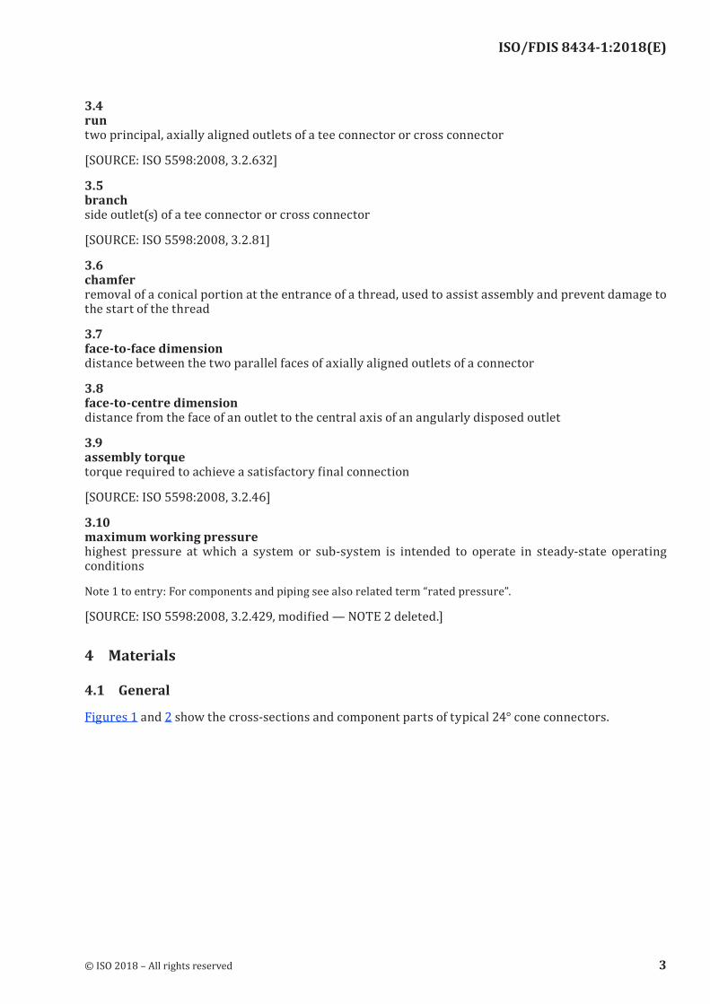
3.4runtwo principal, axially aligned outlets of a tee connector or cross connector
[SOURCE: ISO 5598:2008, 3.2.632]
3.5branchside outlet(s) of a tee connector or cross connector
[SOURCE: ISO 5598:2008, 3.2.81]
3.6chamferremoval of a conical portion at the entrance of a thread, used to assist assembly and prevent damage to the start of the thread
3.7face‑to‑face dimensiondistance between the two parallel faces of axially aligned outlets of a connector
3.8face‑to‑centre dimensiondistance from the face of an outlet to the central axis of an angularly disposed outlet
3.9assembly torquetorque required to achieve a satisfactory final connection
[SOURCE: ISO 5598:2008, 3.2.46]
3.10maximum working pressurehighest pressure at which a system or sub-system is intended to operate in steady-state operating conditions
Note 1 to entry: For components and piping see also related term “rated pressure”.
[SOURCE: ISO 5598:2008, 3.2.429, modified — NOTE 2 deleted.]
4 Materials
4.1 General
Figures 1 and 2 show the cross-sections and component parts of typical 24° cone connectors.
© ISO 2018 – All rights reserved 3
ISO/FDIS 8434-1:2018(E)
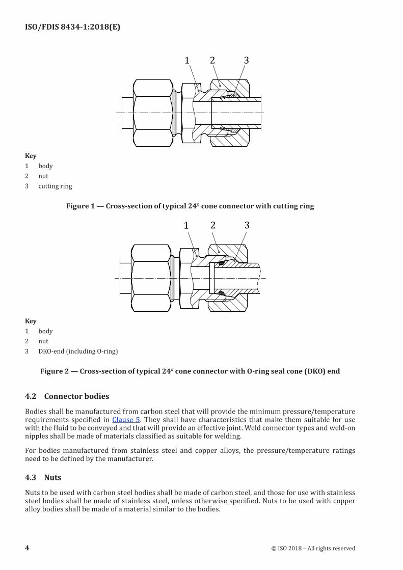
Key1 body2 nut3 cutting ring
Figure 1 — Cross‑section of typical 24° cone connector with cutting ring
Key1 body2 nut3 DKO-end (including O-ring)
Figure 2 — Cross‑section of typical 24° cone connector with O‑ring seal cone (DKO) end
4.2 Connector bodies
Bodies shall be manufactured from carbon steel that will provide the minimum pressure/temperature requirements specified in Clause 5. They shall have characteristics that make them suitable for use with the fluid to be conveyed and that will provide an effective joint. Weld connector types and weld-on nipples shall be made of materials classified as suitable for welding.
For bodies manufactured from stainless steel and copper alloys, the pressure/temperature ratings need to be defined by the manufacturer.
4.3 Nuts
Nuts to be used with carbon steel bodies shall be made of carbon steel, and those for use with stainless steel bodies shall be made of stainless steel, unless otherwise specified. Nuts to be used with copper alloy bodies shall be made of a material similar to the bodies.
4 © ISO 2018 – All rights reserved
ISO/FDIS 8434-1:2018(E)
4.4 Cutting rings
4.4.1 The ring material shall be compatible with the fluid to be conveyed and provide an effective joint.
4.4.2 Steel cutting rings are to be used in combination with other steel connector components and steel tubes.
4.4.3 Stainless steel cutting rings are to be used in combination with other stainless steel connector components and stainless steel tubes.
4.4.4 Brass cutting rings are to be used in combination with other brass connector components and copper tubes.
4.4.5 Other combinations of materials shall be agreed upon between the purchaser and supplier.
4.5 O‑rings
Unless otherwise specified, for use with petroleum-based hydraulic fluids at the pressure and temperature requirements given in Clause 5 and Table 1, O-rings for use with connectors in accordance with this document shall be made of acrylonitrile-butadiene rubber (NBR) with a hardness of (90 ± 5) IRHD, measured in accordance with ISO 48, and shall conform to the dimensions given in Table 7 and shall meet or exceed the O-ring quality acceptance criteria of ISO 3601-3, grade N. In those cases where the pressure and temperature requirements of this document and/or the hydraulic fluid used in the system differ from those specified in Clause 5 and Table 1, the connector manufacturer shall be consulted to ensure that an appropriate O-ring material is selected.
5 Pressure/temperature requirements
5.1 Connectors in conformance with this document made of carbon steel shall meet or exceed without leakage the requirements from a vacuum of 6,5 kPa (0,065 bar) absolute pressure to the working pressures given in Tables 1 to 3 when used at temperatures between −40 °C and +120 °C with petroleum-base hydraulic fluids.
5.2 Connectors conforming to this document can contain elastomeric seals. Unless otherwise specified, connectors are made and delivered with elastomeric seals for use within the specified working temperature range with petroleum-base hydraulic fluids. The use of these connectors and elastomeric seals with other hydraulic fluids may result in a reduced working temperature range or may render the connectors unsuitable for the application. Manufacturers may supply, upon request, connectors with elastomeric seals for use with hydraulic fluids other than petroleum-base hydraulic fluids which will meet the specified working temperature range of the connectors.
5.3 The connector assembly shall meet or exceed all applicable performance requirements given in Clause 15. Testing shall be conducted at room temperature.
5.4 For applications under conditions other than the pressure and/or temperature limits given in Tables 1 to 3 and in 5.1 and 5.3, the manufacturer shall be consulted.
5.5 According to different applications and different pressure ratings, there are three series of connector, designated by
— LL, for extra light-duty,
— L, for light-duty, and
— S, for heavy-duty.
© ISO 2018 – All rights reserved 5
ISO/FDIS 8434-1:2018(E)
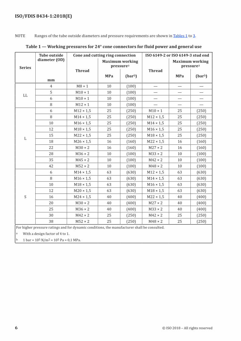
NOTE Ranges of the tube outside diameters and pressure requirements are shown in Tables 1 to 3.
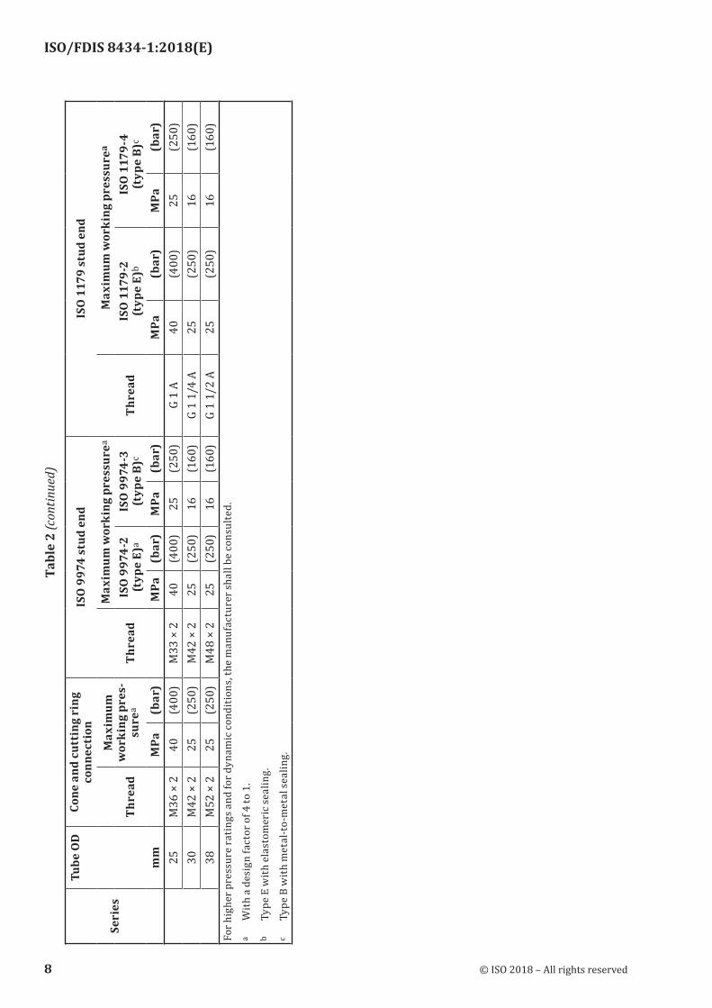
Table 1 — Working pressures for 24° cone connectors for fluid power and general use
Series
Tube outside diameter (OD)
mm
Cone and cutting ring connection ISO 6149‑2 or ISO 6149‑3 stud end
Thread
Maximum working pressurea
Thread
Maximum working pressurea
MPa (barb) MPa (barb)
LL
4 M8 × 1 10 (100) — — —5 M10 × 1 10 (100) — — —6 M10 × 1 10 (100) — — —8 M12 × 1 10 (100) — — —
L
6 M12 × 1,5 25 (250) M10 × 1 25 (250)8 M14 × 1,5 25 (250) M12 × 1,5 25 (250)
10 M16 × 1,5 25 (250) M14 × 1,5 25 (250)12 M18 × 1,5 25 (250) M16 × 1,5 25 (250)15 M22 × 1,5 25 (250) M18 × 1,5 25 (250)18 M26 × 1,5 16 (160) M22 × 1,5 16 (160)22 M30 × 2 16 (160) M27 × 2 16 (160)28 M36 × 2 10 (100) M33 × 2 10 (100)35 M45 × 2 10 (100) M42 × 2 10 (100)42 M52 × 2 10 (100) M48 × 2 10 (100)
S
6 M14 × 1,5 63 (630) M12 × 1,5 63 (630)8 M16 × 1,5 63 (630) M14 × 1,5 63 (630)
10 M18 × 1,5 63 (630) M16 × 1,5 63 (630)12 M20 × 1,5 63 (630) M18 × 1,5 63 (630)16 M24 × 1,5 40 (400) M22 × 1,5 40 (400)20 M30 × 2 40 (400) M27 × 2 40 (400)25 M36 × 2 40 (400) M33 × 2 40 (400)30 M42 × 2 25 (250) M42 × 2 25 (250)38 M52 × 2 25 (250) M48 × 2 25 (250)
For higher pressure ratings and for dynamic conditions, the manufacturer shall be consulted.a With a design factor of 4 to 1.b 1 bar = 105 N/m2 = 105 Pa = 0,1 MPa.
6 © ISO 2018 – All rights reserved
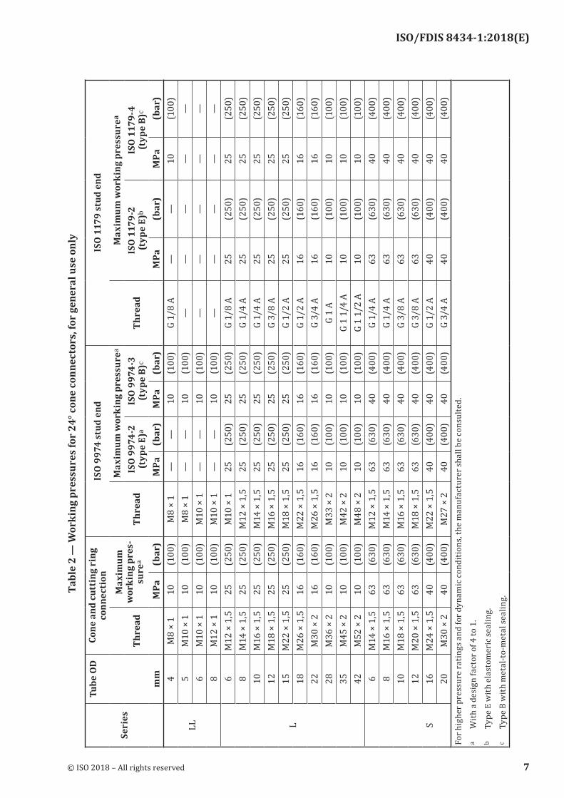
ISO/FDIS 8434-1:2018(E)
Tabl
e 2
— W
orki
ng p
ress
ures
for
24° c
one
conn
ecto
rs, f
or g
ener
al u
se o
nly
Seri
es
Tube
OD
m
m
Cone
and
cut
ting
rin
g co
nnec
tion
ISO
997
4 st
ud e
ndIS
O 1
179
stud
end
Thre
ad
Max
imum
w
orki
ng p
res-
sure
aTh
read
Max
imum
wor
king
pre
ssur
ea
Thre
ad
Max
imum
wor
king
pre
ssur
ea
ISO
997
4-2
(typ
e E)
aIS
O 9
974-
3 (t
ype
B)c
ISO
117
9-2
(t
ype
E)b
ISO
117
9-4
(t
ype
B)c
MPa
(bar
)M
Pa(b
ar)
MPa
(bar
)M
Pa(b
ar)
MPa
(bar
)
LL
4M
8 ×
110
(100
)M
8 ×
1—
—10
(100
)G
1/8
A—
—10
(100
)5
M10
× 1
10(1
00)
M8
× 1
——
10(1
00)
——
——
—6
M10
× 1
10(1
00)
M10
× 1
——
10(1
00)
——
——
—8
M12
× 1
10(1
00)
M10
× 1
——
10(1
00)
——
——
—
L
6M
12 ×
1,5
25(2
50)
M10
× 1
25(2
50)
25(2
50)
G 1/
8 A
25(2
50)
25(2
50)
8M
14 ×
1,5
25(2
50)
M12
× 1
,525
(250
)25
(250
)G
1/4
A25
(250
)25
(250
)10
M16
× 1
,525
(250
)M
14 ×
1,5
25(2
50)
25(2
50)
G 1/
4 A
25(2
50)
25(2
50)
12M
18 ×
1,5
25(2
50)
M16
× 1
,525
(250
)25
(250
)G
3/8
A25
(250
)25
(250
)15
M22
× 1
,525
(250
)M
18 ×
1,5
25(2
50)
25(2
50)
G 1/
2 A
25(2
50)
25(2
50)
18M
26 ×
1,5
16(1
60)
M22
× 1
,516
(160
)16
(160
)G
1/2
A16
(160
)16
(160
)22
M30
× 2
16(1
60)
M26
× 1
,516
(160
)16
(160
)G
3/4
A16
(160
)16
(160
)28
M36
× 2
10(1
00)
M33
× 2
10(1
00)
10(1
00)
G 1
A10
(100
)10
(100
)35
M45
× 2
10(1
00)
M42
× 2
10(1
00)
10(1
00)
G 1
1/4
A10
(100
)10
(100
)42
M52
× 2
10(1
00)
M48
× 2
10(1
00)
10(1
00)
G 1
1/2
A10
(100
)10
(100
)6
M14
× 1
,563
(630
)M
12 ×
1,5
63(6
30)
40(4
00)
G 1/
4 A
63(6
30)
40(4
00)
8M
16 ×
1,5
63(6
30)
M14
× 1
,563
(630
)40
(400
)G
1/4
A63
(630
)40
(400
)10
M18
× 1
,563
(630
)M
16 ×
1,5
63(6
30)
40(4
00)
G 3/
8 A
63(6
30)
40(4
00)
12M
20 ×
1,5
63(6
30)
M18
× 1
,563
(630
)40
(400
)G
3/8
A63
(630
)40
(400
)S
16M
24 ×
1,5
40(4
00)
M22
× 1
,540
(400
)40
(400
)G
1/2
A40
(400
)40
(400
)20
M30
× 2
40(4
00)
M27
× 2
40(4
00)
40(4
00)
G 3/
4 A
40(4
00)
40(4
00)
For h
ighe
r pre
ssur
e ra
ting
s and
for d
ynam
ic c
ondi
tions
, the
man
ufac
ture
r sha
ll be
con
sulte
d.a
With
a d
esig
n fa
ctor
of 4
to 1
.b
Type
E w
ith e
last
omer
ic se
alin
g.c
Type
B w
ith m
etal
-to-
met
al se
alin
g.
© ISO 2018 – All rights reserved 7
ISO/FDIS 8434-1:2018(E)
Seri
es
Tube
OD
m
m
Cone
and
cut
ting
rin
g co
nnec
tion
ISO
997
4 st
ud e
ndIS
O 1
179
stud
end
Thre
ad
Max
imum
w
orki
ng p
res-
sure
aTh
read
Max
imum
wor
king
pre
ssur
ea
Thre
ad
Max
imum
wor
king
pre
ssur
ea
ISO
997
4-2
(typ
e E)
aIS
O 9
974-
3 (t
ype
B)c
ISO
117
9-2
(t
ype
E)b
ISO
117
9-4
(t
ype
B)c
MPa
(bar
)M
Pa(b
ar)
MPa
(bar
)M
Pa(b
ar)
MPa
(bar
)25
M36
× 2
40(4
00)
M33
× 2
40(4
00)
25(2
50)
G 1
A40
(400
)25
(250
)30
M42
× 2
25(2
50)
M42
× 2
25(2
50)
16(1
60)
G 1
1/4
A25
(250
)16
(160
)38
M52
× 2
25(2
50)
M48
× 2
25(2
50)
16(1
60)
G 1
1/2
A25
(250
)16
(160
)Fo
r hig
her p
ress
ure
rati
ngs a
nd fo
r dyn
amic
con
ditio
ns, t
he m
anuf
actu
rer s
hall
be c
onsu
lted.
a W
ith a
des
ign
fact
or o
f 4 to
1.
b Ty
pe E
with
ela
stom
eric
seal
ing.
c Ty
pe B
with
met
al-t
o-m
etal
seal
ing.
Tabl
e 2
(con
tinue
d)
8 © ISO 2018 – All rights reserved
ISO/FDIS 8434-1:2018(E)
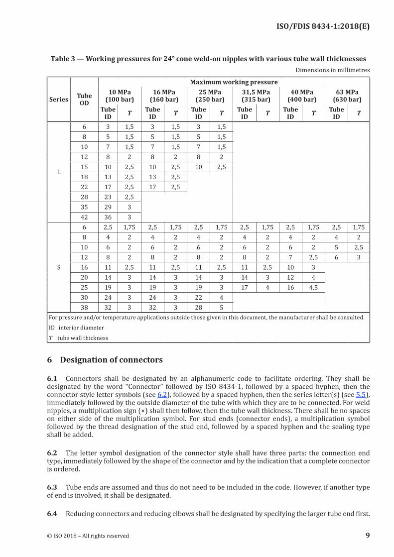
Table 3 — Working pressures for 24° cone weld‑on nipples with various tube wall thicknessesDimensions in millimetres
Series Tube OD
Maximum working pressure10 MPa
(100 bar)16 MPa
(160 bar)25 MPa
(250 bar)31,5 MPa (315 bar)
40 MPa (400 bar)
63 MPa (630 bar)
Tube ID T Tube
ID T Tube ID T Tube
ID T Tube ID T Tube
ID T
L
6 3 1,5 3 1,5 3 1,5 8 5 1,5 5 1,5 5 1,5
10 7 1,5 7 1,5 7 1,5 12 8 2 8 2 8 2 15 10 2,5 10 2,5 10 2,5 18 13 2,5 13 2,5 22 17 2,5 17 2,5 28 23 2,5 35 29 3 42 36 3
S
6 2,5 1,75 2,5 1,75 2,5 1,75 2,5 1,75 2,5 1,75 2,5 1,758 4 2 4 2 4 2 4 2 4 2 4 2
10 6 2 6 2 6 2 6 2 6 2 5 2,512 8 2 8 2 8 2 8 2 7 2,5 6 316 11 2,5 11 2,5 11 2,5 11 2,5 10 3 20 14 3 14 3 14 3 14 3 12 425 19 3 19 3 19 3 17 4 16 4,530 24 3 24 3 22 4 38 32 3 32 3 28 5
For pressure and/or temperature applications outside those given in this document, the manufacturer shall be consulted.
ID interior diameter
T tube wall thickness
6 Designation of connectors
6.1 Connectors shall be designated by an alphanumeric code to facilitate ordering. They shall be designated by the word “Connector” followed by ISO 8434-1, followed by a spaced hyphen, then the connector style letter symbols (see 6.2), followed by a spaced hyphen, then the series letter(s) (see 5.5), immediately followed by the outside diameter of the tube with which they are to be connected. For weld nipples, a multiplication sign (×) shall then follow, then the tube wall thickness. There shall be no spaces on either side of the multiplication symbol. For stud ends (connector ends), a multiplication symbol followed by the thread designation of the stud end, followed by a spaced hyphen and the sealing type shall be added.
6.2 The letter symbol designation of the connector style shall have three parts: the connection end type, immediately followed by the shape of the connector and by the indication that a complete connector is ordered.
6.3 Tube ends are assumed and thus do not need to be included in the code. However, if another type of end is involved, it shall be designated.
6.4 Reducing connectors and reducing elbows shall be designated by specifying the larger tube end first.
© ISO 2018 – All rights reserved 9
ISO/FDIS 8434-1:2018(E)
6.5 Stud connectors (see Figures 3 and 4) shall be designated by specifying the tube end first, then the thread size for the stud end with the sealing type letter.
6.6 For tee connectors, the order of designation of the connection ends shall start with the larger end on the run followed by the tee.
6.7 For cross connectors, the order of designation of the connection ends shall be from left to right, followed by top to bottom, with the larger ends on the left and at the top.
6.8 If the connector has a swivel, it shall be designated first. On run tees the branch end shall follow.
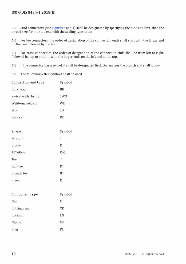
6.9 The following letter symbols shall be used.
Connection end type Symbol
Bulkhead BH
Swivel with O-ring SWO
Weld-on/weld-in WD
Stud SD
Reducer RD
Shape Symbol
Straight S
Elbow E
45° elbow E45
Tee T
Run tee RT
Branch tee BT
Cross K
Component type Symbol
Nut N
Cutting ring CR
Locknut LN
Nipple NP
Plug PL
10 © ISO 2018 – All rights reserved
ISO/FDIS 8434-1:2018(E)
Completeness indication Symbol
Complete connector C
Stud end sealing types Symbol
Metal-to-metal sealing B
Elastomeric sealing E
O-ring sealing F
6.10 Examples of compression connectors and designations are given below and in Figures 3 to 5.
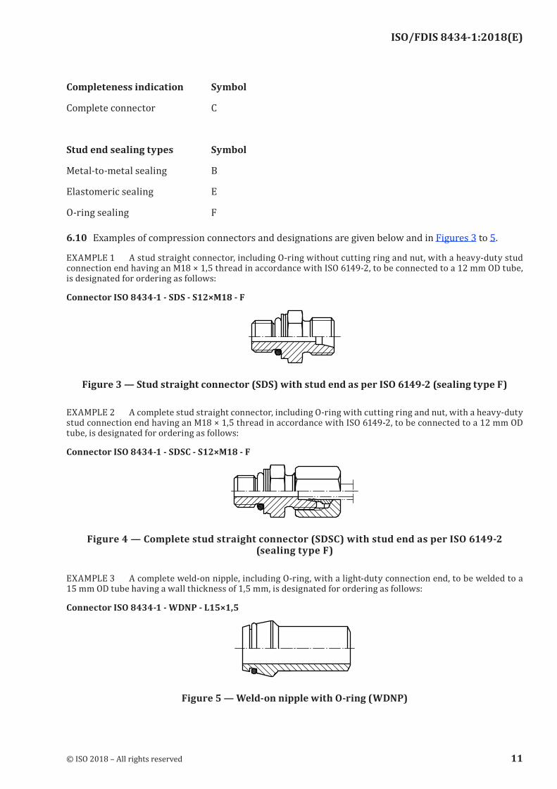
EXAMPLE 1 A stud straight connector, including O-ring without cutting ring and nut, with a heavy-duty stud connection end having an M18 × 1,5 thread in accordance with ISO 6149-2, to be connected to a 12 mm OD tube, is designated for ordering as follows:
Connector ISO 8434-1 - SDS - S12×M18 - F
Figure 3 — Stud straight connector (SDS) with stud end as per ISO 6149‑2 (sealing type F)
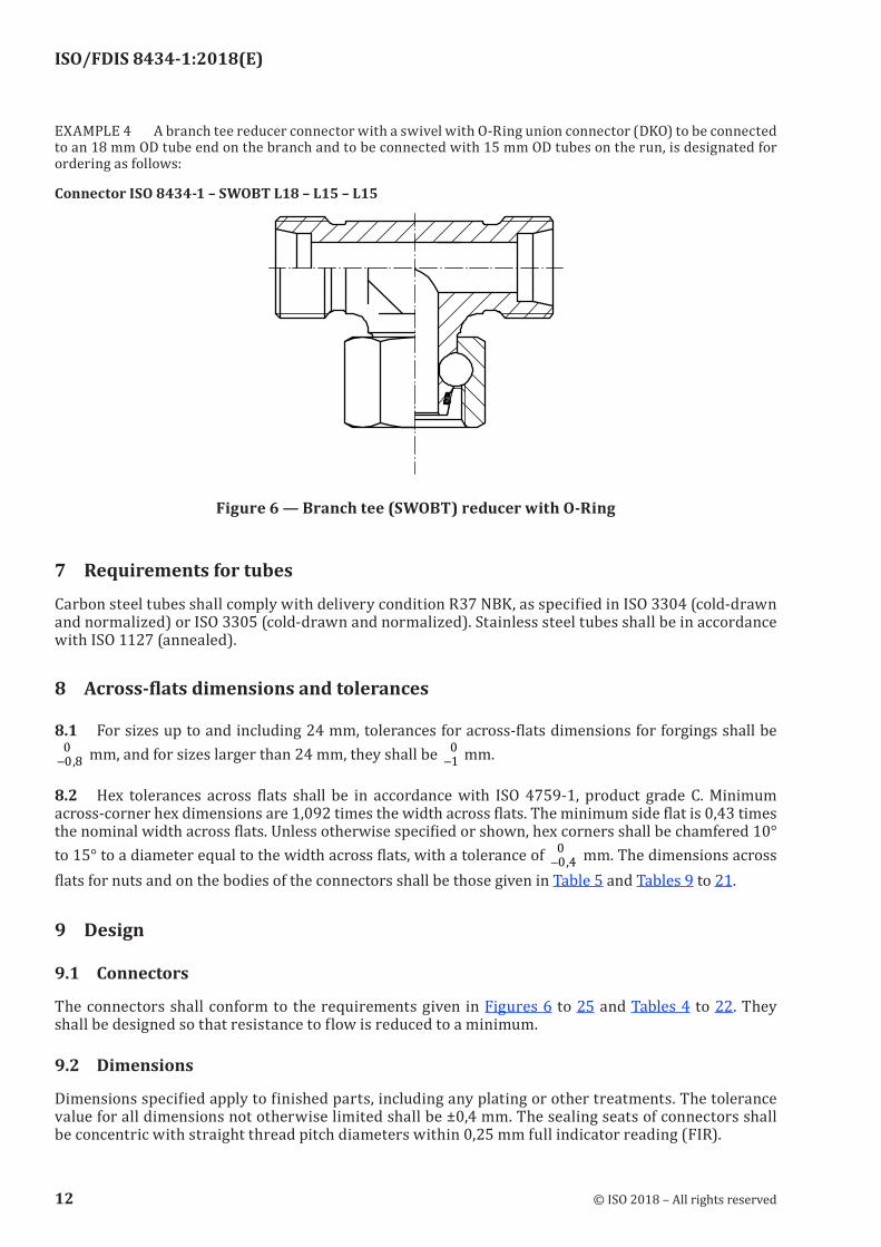
EXAMPLE 2 A complete stud straight connector, including O-ring with cutting ring and nut, with a heavy-duty stud connection end having an M18 × 1,5 thread in accordance with ISO 6149-2, to be connected to a 12 mm OD tube, is designated for ordering as follows:
Connector ISO 8434-1 - SDSC - S12×M18 - F
Figure 4 — Complete stud straight connector (SDSC) with stud end as per ISO 6149-2 (sealing type F)
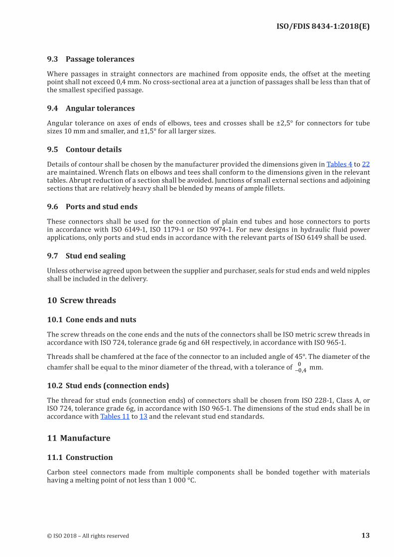
EXAMPLE 3 A complete weld-on nipple, including O-ring, with a light-duty connection end, to be welded to a 15 mm OD tube having a wall thickness of 1,5 mm, is designated for ordering as follows:
Connector ISO 8434‑1 ‑ WDNP ‑ L15×1,5
Figure 5 — Weld‑on nipple with O‑ring (WDNP)
© ISO 2018 – All rights reserved 11
ISO/FDIS 8434-1:2018(E)
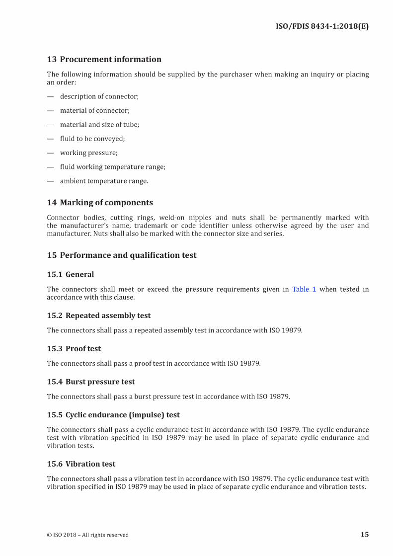
EXAMPLE 4 A branch tee reducer connector with a swivel with O-Ring union connector (DKO) to be connected to an 18 mm OD tube end on the branch and to be connected with 15 mm OD tubes on the run, is designated for ordering as follows:
Connector ISO 8434‑1 – SWOBT L18 – L15 – L15
Figure 6 — Branch tee (SWOBT) reducer with O‑Ring
7 Requirements for tubes
Carbon steel tubes shall comply with delivery condition R37 NBK, as specified in ISO 3304 (cold-drawn and normalized) or ISO 3305 (cold-drawn and normalized). Stainless steel tubes shall be in accordance with ISO 1127 (annealed).
8 Across‑flats dimensions and tolerances
8.1 For sizes up to and including 24 mm, tolerances for across-flats dimensions for forgings shall be
−0 80
, mm, and for sizes larger than 24 mm, they shall be −1
0 mm.
8.2 Hex tolerances across flats shall be in accordance with ISO 4759-1, product grade C. Minimum across-corner hex dimensions are 1,092 times the width across flats. The minimum side flat is 0,43 times the nominal width across flats. Unless otherwise specified or shown, hex corners shall be chamfered 10° to 15° to a diameter equal to the width across flats, with a tolerance of −0 4
0
, mm. The dimensions across
flats for nuts and on the bodies of the connectors shall be those given in Table 5 and Tables 9 to 21.
9 Design
9.1 Connectors
The connectors shall conform to the requirements given in Figures 6 to 25 and Tables 4 to 22. They shall be designed so that resistance to flow is reduced to a minimum.
9.2 Dimensions
Dimensions specified apply to finished parts, including any plating or other treatments. The tolerance value for all dimensions not otherwise limited shall be ±0,4 mm. The sealing seats of connectors shall be concentric with straight thread pitch diameters within 0,25 mm full indicator reading (FIR).
12 © ISO 2018 – All rights reserved
ISO/FDIS 8434-1:2018(E)
9.3 Passage tolerances
Where passages in straight connectors are machined from opposite ends, the offset at the meeting point shall not exceed 0,4 mm. No cross-sectional area at a junction of passages shall be less than that of the smallest specified passage.
9.4 Angular tolerances
Angular tolerance on axes of ends of elbows, tees and crosses shall be ±2,5° for connectors for tube sizes 10 mm and smaller, and ±1,5° for all larger sizes.
9.5 Contour details
Details of contour shall be chosen by the manufacturer provided the dimensions given in Tables 4 to 22 are maintained. Wrench flats on elbows and tees shall conform to the dimensions given in the relevant tables. Abrupt reduction of a section shall be avoided. Junctions of small external sections and adjoining sections that are relatively heavy shall be blended by means of ample fillets.
9.6 Ports and stud ends
These connectors shall be used for the connection of plain end tubes and hose connectors to ports in accordance with ISO 6149-1, ISO 1179-1 or ISO 9974-1. For new designs in hydraulic fluid power applications, only ports and stud ends in accordance with the relevant parts of ISO 6149 shall be used.
9.7 Stud end sealing
Unless otherwise agreed upon between the supplier and purchaser, seals for stud ends and weld nipples shall be included in the delivery.
10 Screw threads
10.1 Cone ends and nuts
The screw threads on the cone ends and the nuts of the connectors shall be ISO metric screw threads in accordance with ISO 724, tolerance grade 6g and 6H respectively, in accordance with ISO 965-1.
Threads shall be chamfered at the face of the connector to an included angle of 45°. The diameter of the chamfer shall be equal to the minor diameter of the thread, with a tolerance of −0 4
0
, mm.
10.2 Stud ends (connection ends)
The thread for stud ends (connection ends) of connectors shall be chosen from ISO 228-1, Class A, or ISO 724, tolerance grade 6g, in accordance with ISO 965-1. The dimensions of the stud ends shall be in accordance with Tables 11 to 13 and the relevant stud end standards.
11 Manufacture
11.1 Construction
Carbon steel connectors made from multiple components shall be bonded together with materials having a melting point of not less than 1 000 °C.
© ISO 2018 – All rights reserved 13

ISO/FDIS 8434-1:2018(E)
11.2 Workmanship
The connectors shall be free from defects such as cracks and porosity and shall be deburred. Sharp edges shall be removed on the outside. All machined surfaces shall have a material removal rate surface roughness value of MRR Ra ≤ 6,3, except where otherwise specified in the figures.
11.3 Finish
The external surface and threads of all carbon steel parts shall be plated or coated with a suitable material that passes a 72 h neutral salt spray test in accordance with ISO 9227, unless otherwise agreed upon by the manufacturer and the user. Any appearance of red rust during the salt spray test on any area, excepting the following, shall be considered failure:
— all internal fluid passages;
— edges, such as hex points, serrations and crests of threads, where there may be mechanical deformation of the plating or coating typical of mass-produced parts or shipping effects;
— areas where there is mechanical deformation of the plating or coating caused by crimping, flaring, bending and other post-plate metal-forming operations;
— areas where the parts are suspended or affixed in the test chamber, where condensate can accumulate.
Internal fluid passages shall be protected from corrosion during storage. Weld components shall be protected from corrosion by an oil film or phosphate coating, or by other means that do not negatively affect weldability.
Cadmium plating is not allowed because of environmental concerns. Parts manufactured in accordance with this document shall not be cadmium-plated. Hexavalent chromate coatings are not preferred because of environmental concerns. Changes in plating can affect assembly torques and require requalification, when applicable.
11.4 Corners
Unless otherwise noted, all sharp corners shall be broken to 0,15 mm maximum.
12 Assembly instruction
The assembly of the connectors with the connecting tubes shall be carried out without external loads.
The manufacturer shall draw up assembly instructions for the use of the connectors. These instructions shall include at least the following:
— details relating to material and quality of suitable tubes;
— details concerning the preparation of the selected tube;
— instructions regarding the assembly of the connector, such as the number of wrenching turns or assembly torque;
— recommendations regarding the tools to be used for assembly.
NOTE Assembly instructions for cutting ring connectors are presented in Annex A
14 © ISO 2018 – All rights reserved
ISO/FDIS 8434-1:2018(E)
13 Procurement information
The following information should be supplied by the purchaser when making an inquiry or placing an order:
— description of connector;
— material of connector;
— material and size of tube;
— fluid to be conveyed;
— working pressure;
— fluid working temperature range;
— ambient temperature range.
14 Marking of components
Connector bodies, cutting rings, weld-on nipples and nuts shall be permanently marked with the manufacturer's name, trademark or code identifier unless otherwise agreed by the user and manufacturer. Nuts shall also be marked with the connector size and series.
15 Performance and qualification test
15.1 General
The connectors shall meet or exceed the pressure requirements given in Table 1 when tested in accordance with this clause.
15.2 Repeated assembly test
The connectors shall pass a repeated assembly test in accordance with ISO 19879.
15.3 Proof test
The connectors shall pass a proof test in accordance with ISO 19879.
15.4 Burst pressure test
The connectors shall pass a burst pressure test in accordance with ISO 19879.
15.5 Cyclic endurance (impulse) test
The connectors shall pass a cyclic endurance test in accordance with ISO 19879. The cyclic endurance test with vibration specified in ISO 19879 may be used in place of separate cyclic endurance and vibration tests.
15.6 Vibration test
The connectors shall pass a vibration test in accordance with ISO 19879. The cyclic endurance test with vibration specified in ISO 19879 may be used in place of separate cyclic endurance and vibration tests.
© ISO 2018 – All rights reserved 15
ISO/FDIS 8434-1:2018(E)
15.7 Leakage (gas) test
The connectors shall pass a leakage (gas) test in accordance with ISO 19879.
15.8 Overtightening test
15.8.1 Connectors with cutting rings
15.8.1.1 For each size, three samples each of the cutting ring connection ends shall be tested.
15.8.1.2 Tighten the cutting ring connection end to finger-tight position plus the number of turns recommended by the manufacturer, and record the resulting torque. Apply an overload of 30 % of the recorded torque, not to exceed 100 Nm. The connection shall be capable of withstanding this overload with no indication of the following failures:
— the nut cannot be removed and swivels freely after breakaway;
— visible cracks or severe deformation appear that would render the connector component unusable.
15.8.2 Connectors with O‑ring seal cone (DKO)
15.8.2.1 For each size, three samples of the O-ring seal cone (DKO) ends shall be tested.
15.8.2.2 Apply the manufacturer’s recommended torque plus an overload of 30 % of the recommended torque, not to exceed 100 Nm. The connection shall be capable of withstanding this overload with no indication of the following failures:
— the nut cannot be removed and swivels freely after breakaway;
— visible cracks or severe deformation appear that would render the connector component unusable.
15.9 Vacuum test
The connectors shall pass a vacuum test in accordance with ISO 19879.
16 Identification statement (reference to this document)
Use the following statement in test reports, catalogues and sales literature when electing to comply with this document:
“Dimensions and design for 24° cone connectors in accordance with ISO 8434-1, Metallic tube connections for fluid power and general use — Part 1: 24° cone connectors.”
Surface roughness values in micrometres.
16 © ISO 2018 – All rights reserved
ISO/FDIS 8434-1:2018(E)
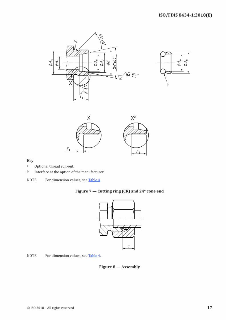
Keya Optional thread run-out.b Interface at the option of the manufacturer.
NOTE For dimension values, see Table 4.
Figure 7 — Cutting ring (CR) and 24° cone end
NOTE For dimension values, see Table 4.
Figure 8 — Assembly
© ISO 2018 – All rights reserved 17
ISO/FDIS 8434-1:2018(E)
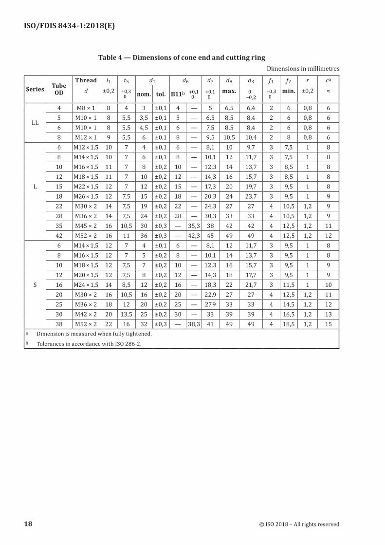
Table 4 — Dimensions of cone end and cutting ringDimensions in millimetres
Series Tube OD
Thread
d
i1±0,2
t5
00 3+ ,
d1 d6 d7 d8
max.
d3
−0 20
,
f1
0
0 3+ ,
f2
min.
r
±0,2
ca
≈nom. tol. B11b00 1+ ,
00 1+ ,
LL
4 M8 × 1 8 4 3 ±0,1 4 — 5 6,5 6,4 2 6 0,8 65 M10 × 1 8 5,5 3,5 ±0,1 5 — 6,5 8,5 8,4 2 6 0,8 66 M10 × 1 8 5,5 4,5 ±0,1 6 — 7,5 8,5 8,4 2 6 0,8 68 M12 × 1 9 5,5 6 ±0,1 8 — 9,5 10,5 10,4 2 8 0,8 66 M12 × 1,5 10 7 4 ±0,1 6 — 8,1 10 9,7 3 7,5 1 88 M14 × 1,5 10 7 6 ±0,1 8 — 10,1 12 11,7 3 7,5 1 8
10 M16 × 1,5 11 7 8 ±0,2 10 — 12,3 14 13,7 3 8,5 1 812 M18 × 1,5 11 7 10 ±0,2 12 — 14,3 16 15,7 3 8,5 1 8
L 15 M22 × 1,5 12 7 12 ±0,2 15 — 17,3 20 19,7 3 9,5 1 818 M26 × 1,5 12 7,5 15 ±0,2 18 — 20,3 24 23,7 3 9,5 1 922 M30 × 2 14 7,5 19 ±0,2 22 — 24,3 27 27 4 10,5 1,2 928 M36 × 2 14 7,5 24 ±0,2 28 — 30,3 33 33 4 10,5 1,2 935 M45 × 2 16 10,5 30 ±0,3 — 35,3 38 42 42 4 12,5 1,2 1142 M52 × 2 16 11 36 ±0,3 — 42,3 45 49 49 4 12,5 1,2 126 M14 × 1,5 12 7 4 ±0,1 6 — 8,1 12 11,7 3 9,5 1 88 M16 × 1,5 12 7 5 ±0,2 8 — 10,1 14 13,7 3 9,5 1 8
10 M18 × 1,5 12 7,5 7 ±0,2 10 — 12,3 16 15,7 3 9,5 1 912 M20 × 1,5 12 7,5 8 ±0,2 12 — 14,3 18 17,7 3 9,5 1 9
S 16 M24 × 1,5 14 8,5 12 ±0,2 16 — 18,3 22 21,7 3 11,5 1 1020 M30 × 2 16 10,5 16 ±0,2 20 — 22,9 27 27 4 12,5 1,2 1125 M36 × 2 18 12 20 ±0,2 25 — 27,9 33 33 4 14,5 1,2 1230 M42 × 2 20 13,5 25 ±0,2 30 — 33 39 39 4 16,5 1,2 1338 M52 × 2 22 16 32 ±0,3 — 38,3 41 49 49 4 18,5 1,2 15
a Dimension is measured when fully tightened.b Tolerances in accordance with ISO 286-2.
18 © ISO 2018 – All rights reserved
ISO/FDIS 8434-1:2018(E)
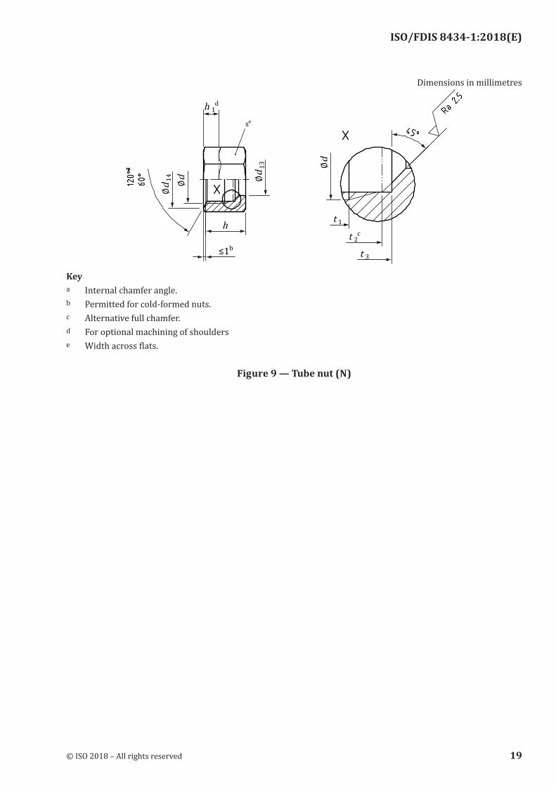
Dimensions in millimetres
Keya Internal chamfer angle.b Permitted for cold-formed nuts.c Alternative full chamfer.d For optional machining of shoulderse Width across flats.
Figure 9 — Tube nut (N)
© ISO 2018 – All rights reserved 19
ISO/FDIS 8434-1:2018(E)
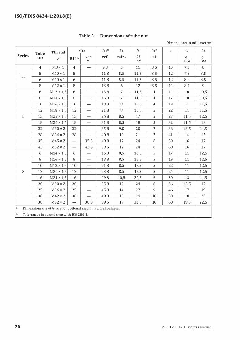
Table 5 — Dimensions of tube nutDimensions in millimetres
Series Tube OD
Threadd
d13 d14a
ref.t1
min.h
−+0 20 5,,
h1a
±1s t2
+0 20
,
t3
+0 20
,B11b
00 1+ ,
LL
4 M8 × 1 4 — 9,8 5 11 3,5 10 7,5 85 M10 × 1 5 — 11,8 5,5 11,5 3,5 12 7,8 8,56 M10 × 1 6 — 11,8 5,5 11,5 3,5 12 8,2 8,58 M12 × 1 8 — 13,8 6 12 3,5 14 8,7 96 M12 × 1,5 6 — 13,8 7 14,5 4 14 10 10,58 M14 × 1,5 8 — 16,8 7 14,5 4 17 10 10,5
10 M16 × 1,5 10 — 18,8 8 15,5 4 19 11 11,512 M18 × 1,5 12 — 21,8 8 15,5 5 22 11 11,5
L 15 M22 × 1,5 15 — 26,8 8,5 17 5 27 11,5 12,518 M26 × 1,5 18 — 31,8 8,5 18 5 32 11,5 1322 M30 × 2 22 — 35,8 9,5 20 7 36 13,5 14,528 M36 × 2 28 — 40,8 10 21 7 41 14 1535 M45 × 2 — 35,3 49,8 12 24 8 50 16 1742 M52 × 2 — 42,3 59,6 12 24 8 60 16 176 M14 × 1,5 6 — 16,8 8,5 16,5 5 17 11 12,58 M16 × 1,5 8 — 18,8 8,5 16,5 5 19 11 12,5
10 M18 × 1,5 10 — 21,8 8,5 17,5 5 22 11 12,5S 12 M20 × 1,5 12 — 23,8 8,5 17,5 5 24 11 12,5
16 M24 × 1,5 16 — 29,8 10,5 20,5 6 30 13 14,520 M30 × 2 20 — 35,8 12 24 8 36 15,5 1725 M36 × 2 25 — 45,8 14 27 9 46 17 1930 M42 × 2 30 — 49,8 15 29 10 50 18 2038 M52 × 2 — 38,3 59,6 17 32,5 10 60 19,5 22,5
a Dimensions d14 et h1 are for optional machining of shoulders.b Tolerances in accordance with ISO 286-2.
20 © ISO 2018 – All rights reserved
ISO/FDIS 8434-1:2018(E)
Dimensions in millimetres Surface roughness values in micrometres
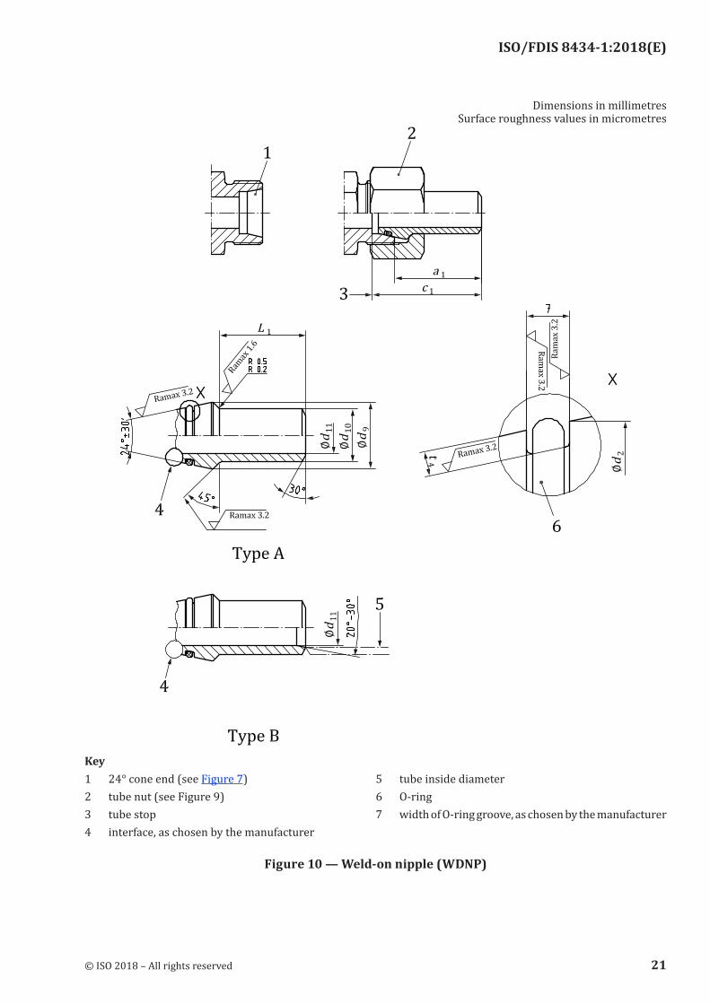
Key1 24° cone end (see Figure 7) 5 tube inside diameter2 tube nut (see Figure 9) 6 O-ring3 tube stop 7 width of O-ring groove, as chosen by the manufacturer4 interface, as chosen by the manufacturer
Figure 10 — Weld‑on nipple (WDNP)
© ISO 2018 – All rights reserved 21
ISO/FDIS 8434-1:2018(E)
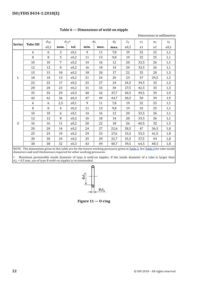
Table 6 — Dimensions of weld‑on nippleDimensions in millimetres
Series Tube ODd10
±0,1d11a d9 d2
max.L1
±0,2c1
±1a1
±1t4
±0,1nom. tol. min. max.6 6 3 ±0,1 9 11 7,8 19 32 25 1,18 8 5 ±0,2 11 13 9,8 19 32 25 1,1
10 10 7 ±0,2 14 16 12 20 33,5 26 1,112 12 8 ±0,2 16 18 14 20 33,5 26 1,115 15 10 ±0,2 18 20 17 22 35 28 1,5
L 18 18 13 ±0,2 21 24 20 23 37 29,5 1,522 22 17 ±0,2 25 27 24 24,5 39,5 32 1,528 28 23 ±0,2 31 33 30 27,5 42,5 35 1,535 35 29 ±0,3 40 42 37,7 30,5 49,5 39 1,942 42 36 ±0,3 47 49 44,7 30,5 50 39 1,96 6 2,5 ±0,1 9 11 7,8 19 32 25 1,18 8 4 ±0,2 11 13 9,8 19 32 25 1,1
10 10 6 ±0,1 14 16 12 20 33,5 26 1,112 12 8 ±0,2 16 18 14 20 33,5 26 1,1
S 16 16 11 ±0,2 20 22 18 26 40,5 32 1,520 20 14 ±0,2 24 27 22,6 28,5 47 36,5 1,825 25 19 ±0,2 29 33 27,6 33,5 53,5 41,5 1,830 30 24 ±0,2 35 39 32,7 35,5 57,5 44 1,838 38 32 ±0,3 43 49 40,7 39,5 64,5 48,5 1,8
NOTE The dimensions given in this table are for the lowest working pressures given in Table 3. See Table 3 for tube inside diameters and wall thicknesses required for other working pressures.a Maximum permissible inside diameter of type A weld-on nipples. If the inside diameter of a tube is larger than d11 + 0,5 mm, use of type B weld-on nipples is recommended.
Figure 11 — O‑ring
22 © ISO 2018 – All rights reserved
ISO/FDIS 8434-1:2018(E)
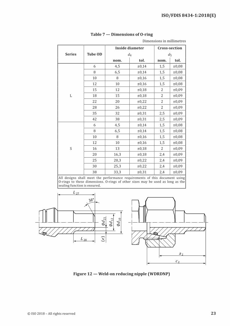
Table 7 — Dimensions of O‑ringDimensions in millimetres
Series Tube ODInside diameter
d4
Cross-sectiond5
nom. tol. nom. tol.6 4,5 ±0,14 1,5 ±0,088 6,5 ±0,14 1,5 ±0,08
10 8 ±0,16 1,5 ±0,0812 10 ±0,16 1,5 ±0,0815 12 ±0,18 2 ±0,09
L 18 15 ±0,18 2 ±0,0922 20 ±0,22 2 ±0,0928 26 ±0,22 2 ±0,0935 32 ±0,31 2,5 ±0,0942 38 ±0,31 2,5 ±0,096 4,5 ±0,14 1,5 ±0,088 6,5 ±0,14 1,5 ±0,08
10 8 ±0,16 1,5 ±0,0812 10 ±0,16 1,5 ±0,08
S 16 13 ±0,18 2 ±0,0920 16,3 ±0,18 2,4 ±0,0925 20,3 ±0,22 2,4 ±0,0930 25,3 ±0,22 2,4 ±0,0938 33,3 ±0,31 2,4 ±0,09
All designs shall meet the performance requirements of this document using O-rings to these dimensions. O-rings of other sizes may be used as long as the sealing function is ensured.
Figure 12 — Weld‑on reducing nipple (WDRDNP)
© ISO 2018 – All rights reserved 23
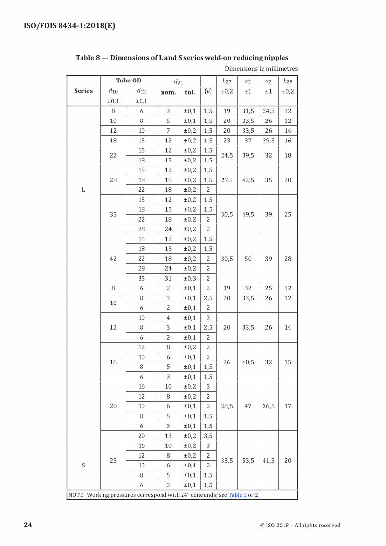
ISO/FDIS 8434-1:2018(E)
Table 8 — Dimensions of L and S series weld‑on reducing nipplesDimensions in millimetres
SeriesTube OD d21
(e)L27
±0,2c2
±1a2
±1L28
±0,2d10
±0,1d12
±0,1nom. tol.
8 6 3 ±0,1 1,5 19 31,5 24,5 1210 8 5 ±0,1 1,5 20 33,5 26 1212 10 7 ±0,2 1,5 20 33,5 26 1418 15 12 ±0,2 1,5 23 37 29,5 16
2215 12 ±0,2 1,5
24,5 39,5 32 1818 15 ±0,2 1,5
2815 12 ±0,2 1,5
27,5 42,5 35 2018 15 ±0,2 1,5L 22 18 ±0,2 2
35
15 12 ±0,2 1,5
30,5 49,5 39 2518 15 ±0,2 1,522 18 ±0,2 228 24 ±0,2 2
42
15 12 ±0,2 1,5
30,5 50 39 2818 15 ±0,2 1,522 18 ±0,2 228 24 ±0,2 235 31 ±0,3 2
8 6 2 ±0,1 2 19 32 25 12
108 3 ±0,1 2,5 20 33,5 26 126 2 ±0,1 2
1210 4 ±0,1 3
20 33,5 26 148 3 ±0,1 2,56 2 ±0,1 2
16
12 8 ±0,2 2
26 40,5 32 1510 6 ±0,1 28 5 ±0,1 1,56 3 ±0,1 1,5
20
16 10 ±0,2 3
28,5 47 36,5 1712 8 ±0,2 210 6 ±0,1 28 5 ±0,1 1,56 3 ±0,1 1,5
25
20 13 ±0,2 3,5
33,5 53,5 41,5 20
16 10 ±0,2 312 8 ±0,2 2
S 10 6 ±0,1 28 5 ±0,1 1,56 3 ±0,1 1,5
NOTE Working pressures correspond with 24° cone ends; see Table 1 or 2.
24 © ISO 2018 – All rights reserved
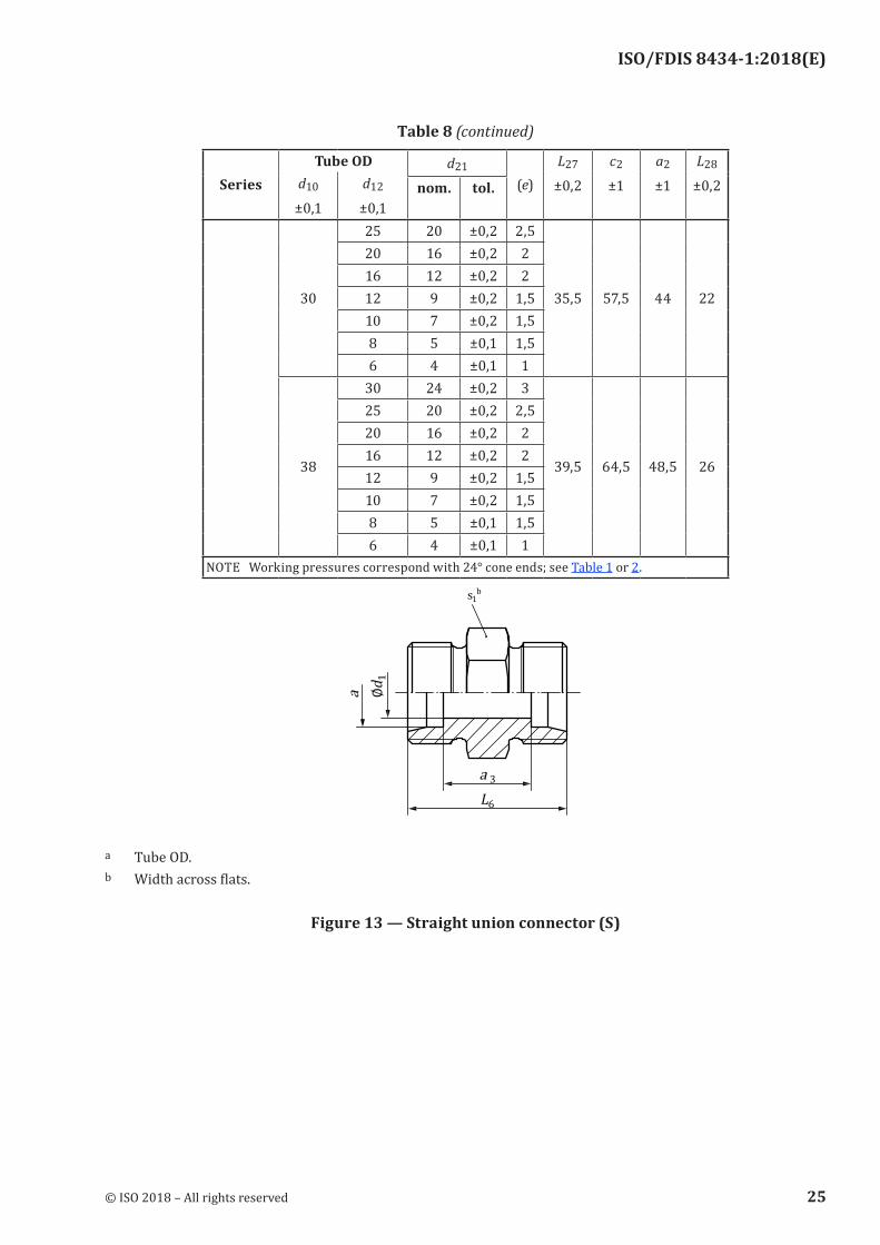
ISO/FDIS 8434-1:2018(E)
SeriesTube OD d21
(e)L27
±0,2c2
±1a2
±1L28
±0,2d10
±0,1d12
±0,1nom. tol.
30
25 20 ±0,2 2,5
35,5 57,5 44 22
20 16 ±0,2 216 12 ±0,2 212 9 ±0,2 1,510 7 ±0,2 1,58 5 ±0,1 1,56 4 ±0,1 1
38
30 24 ±0,2 3
39,5 64,5 48,5 26
25 20 ±0,2 2,520 16 ±0,2 216 12 ±0,2 212 9 ±0,2 1,510 7 ±0,2 1,58 5 ±0,1 1,56 4 ±0,1 1
NOTE Working pressures correspond with 24° cone ends; see Table 1 or 2.
a Tube OD.b Width across flats.
Figure 13 — Straight union connector (S)
Table 8 (continued)
© ISO 2018 – All rights reserved 25
ISO/FDIS 8434-1:2018(E)
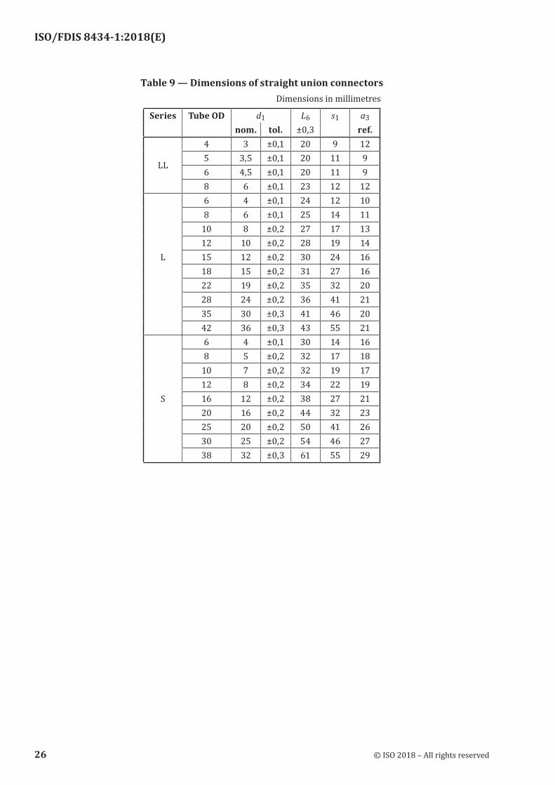
Table 9 — Dimensions of straight union connectorsDimensions in millimetres
Series Tube OD d1 L6 s1 a3
nom. tol. ±0,3 ref.
LL
4 3 ±0,1 20 9 125 3,5 ±0,1 20 11 96 4,5 ±0,1 20 11 98 6 ±0,1 23 12 126 4 ±0,1 24 12 108 6 ±0,1 25 14 11
10 8 ±0,2 27 17 1312 10 ±0,2 28 19 14
L 15 12 ±0,2 30 24 1618 15 ±0,2 31 27 1622 19 ±0,2 35 32 2028 24 ±0,2 36 41 2135 30 ±0,3 41 46 2042 36 ±0,3 43 55 216 4 ±0,1 30 14 168 5 ±0,2 32 17 18
10 7 ±0,2 32 19 1712 8 ±0,2 34 22 19
S 16 12 ±0,2 38 27 2120 16 ±0,2 44 32 2325 20 ±0,2 50 41 2630 25 ±0,2 54 46 2738 32 ±0,3 61 55 29
26 © ISO 2018 – All rights reserved
ISO/FDIS 8434-1:2018(E)
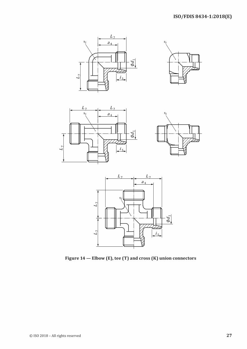
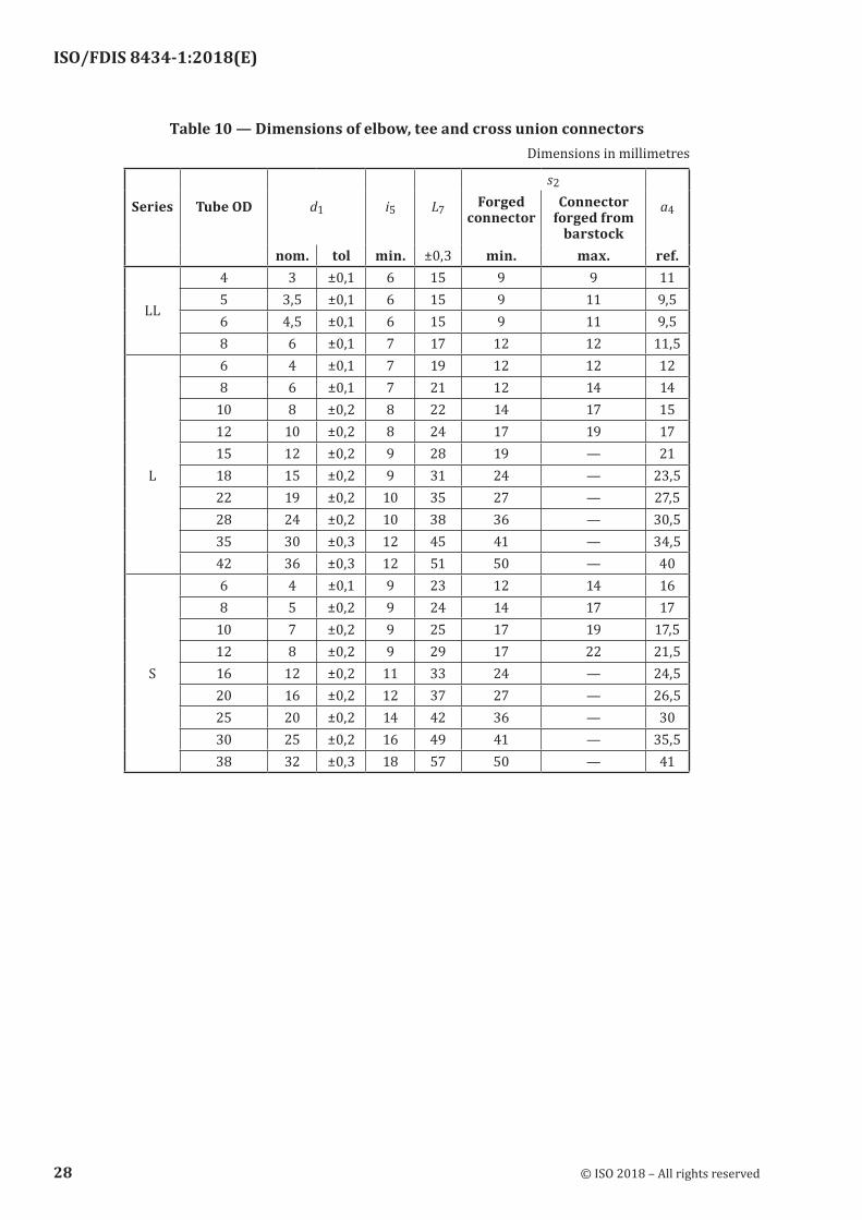
Figure 14 — Elbow (E), tee (T) and cross (K) union connectors
© ISO 2018 – All rights reserved 27
ISO/FDIS 8434-1:2018(E)
Table 10 — Dimensions of elbow, tee and cross union connectorsDimensions in millimetres
Series Tube OD d1 i5 L7
s2
a4Forged connector
Connector forged from
barstock nom. tol min. ±0,3 min. max. ref.
LL
4 3 ±0,1 6 15 9 9 115 3,5 ±0,1 6 15 9 11 9,56 4,5 ±0,1 6 15 9 11 9,58 6 ±0,1 7 17 12 12 11,56 4 ±0,1 7 19 12 12 128 6 ±0,1 7 21 12 14 14
10 8 ±0,2 8 22 14 17 1512 10 ±0,2 8 24 17 19 1715 12 ±0,2 9 28 19 — 21
L 18 15 ±0,2 9 31 24 — 23,522 19 ±0,2 10 35 27 — 27,528 24 ±0,2 10 38 36 — 30,535 30 ±0,3 12 45 41 — 34,542 36 ±0,3 12 51 50 — 406 4 ±0,1 9 23 12 14 168 5 ±0,2 9 24 14 17 17
10 7 ±0,2 9 25 17 19 17,512 8 ±0,2 9 29 17 22 21,5
S 16 12 ±0,2 11 33 24 — 24,520 16 ±0,2 12 37 27 — 26,525 20 ±0,2 14 42 36 — 3030 25 ±0,2 16 49 41 — 35,538 32 ±0,3 18 57 50 — 41
28 © ISO 2018 – All rights reserved
ISO/FDIS 8434-1:2018(E)
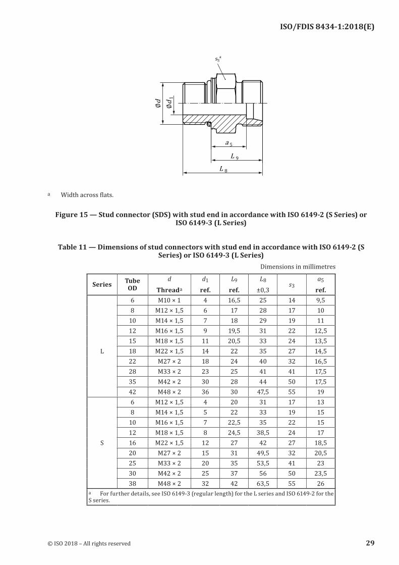
a Width across flats.
Figure 15 — Stud connector (SDS) with stud end in accordance with ISO 6149‑2 (S Series) or ISO 6149-3 (L Series)
Table 11 — Dimensions of stud connectors with stud end in accordance with ISO 6149‑2 (S Series) or ISO 6149-3 (L Series)
Dimensions in millimetres
Series Tube OD
d
Threada
d1
ref.L9
ref.L8
±0,3s3
a5
ref.6 M10 × 1 4 16,5 25 14 9,58 M12 × 1,5 6 17 28 17 10
10 M14 × 1,5 7 18 29 19 1112 M16 × 1,5 9 19,5 31 22 12,515 M18 × 1,5 11 20,5 33 24 13,5
L 18 M22 × 1,5 14 22 35 27 14,522 M27 × 2 18 24 40 32 16,528 M33 × 2 23 25 41 41 17,535 M42 × 2 30 28 44 50 17,542 M48 × 2 36 30 47,5 55 196 M12 × 1,5 4 20 31 17 138 M14 × 1,5 5 22 33 19 15
10 M16 × 1,5 7 22,5 35 22 1512 M18 × 1,5 8 24,5 38,5 24 17
S 16 M22 × 1,5 12 27 42 27 18,520 M27 × 2 15 31 49,5 32 20,525 M33 × 2 20 35 53,5 41 2330 M42 × 2 25 37 56 50 23,538 M48 × 2 32 42 63,5 55 26
a For further details, see ISO 6149-3 (regular length) for the L series and ISO 6149-2 for the S series.
© ISO 2018 – All rights reserved 29
ISO/FDIS 8434-1:2018(E)
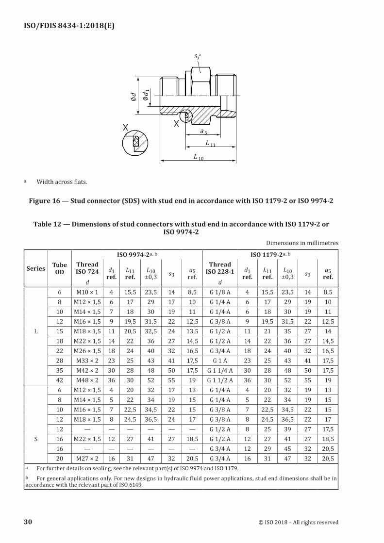
a Width across flats.
Figure 16 — Stud connector (SDS) with stud end in accordance with ISO 1179‑2 or ISO 9974‑2
Table 12 — Dimensions of stud connectors with stud end in accordance with ISO 1179‑2 or ISO 9974-2
Dimensions in millimetres
Series Tube OD
ISO 9974-2a, b ISO 1179-2a, b
Thread ISO 724
d
d1 ref.
L11 ref.
L10 ±0,3 s3
a5 ref.
Thread ISO 228-1
d
d1 ref.
L11 ref.
L10 ±0,3 s3
a5 ref.
6 M10 × 1 4 15,5 23,5 14 8,5 G 1/8 A 4 15,5 23,5 14 8,58 M12 × 1,5 6 17 29 17 10 G 1/4 A 6 17 29 19 10
10 M14 × 1,5 7 18 30 19 11 G 1/4 A 6 18 30 19 1112 M16 × 1,5 9 19,5 31,5 22 12,5 G 3/8 A 9 19,5 31,5 22 12,5
L 15 M18 × 1,5 11 20,5 32,5 24 13,5 G 1/2 A 11 21 35 27 1418 M22 × 1,5 14 22 36 27 14,5 G 1/2 A 14 22 36 27 14,522 M26 × 1,5 18 24 40 32 16,5 G 3/4 A 18 24 40 32 16,528 M33 × 2 23 25 43 41 17,5 G 1 A 23 25 43 41 17,535 M42 × 2 30 28 48 50 17,5 G 1 1/4 A 30 28 48 50 17,542 M48 × 2 36 30 52 55 19 G 1 1/2 A 36 30 52 55 196 M12 × 1,5 4 20 32 17 13 G 1/4 A 4 20 32 19 138 M14 × 1,5 5 22 34 19 15 G 1/4 A 5 22 34 19 15
10 M16 × 1,5 7 22,5 34,5 22 15 G 3/8 A 7 22,5 34,5 22 1512 M18 × 1,5 8 24,5 36,5 24 17 G 3/8 A 8 24,5 36,5 22 1712 — — — — — — G 1/2 A 8 25 39 27 17,5
S 16 M22 × 1,5 12 27 41 27 18,5 G 1/2 A 12 27 41 27 18,516 — — — — — — G 3/4 A 12 29 45 32 20,520 M27 × 2 16 31 47 32 20,5 G 3/4 A 16 31 47 32 20,5
a For further details on sealing, see the relevant part(s) of ISO 9974 and ISO 1179.b For general applications only. For new designs in hydraulic fluid power applications, stud end dimensions shall be in accordance with the relevant part of ISO 6149.
30 © ISO 2018 – All rights reserved
ISO/FDIS 8434-1:2018(E)
Series Tube OD
ISO 9974-2a, b ISO 1179-2a, b
Thread ISO 724
d
d1 ref.
L11 ref.
L10 ±0,3 s3
a5 ref.
Thread ISO 228-1
d
d1 ref.
L11 ref.
L10 ±0,3 s3
a5 ref.
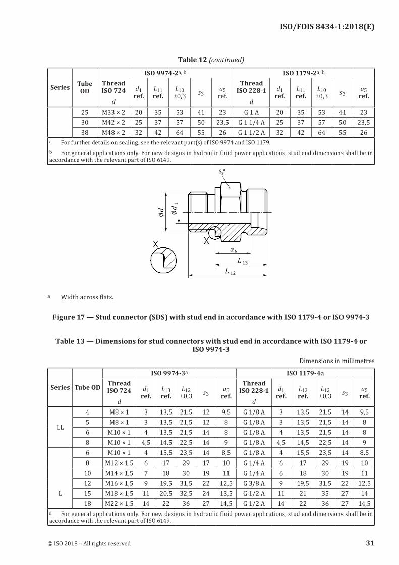
25 M33 × 2 20 35 53 41 23 G 1 A 20 35 53 41 2330 M42 × 2 25 37 57 50 23,5 G 1 1/4 A 25 37 57 50 23,538 M48 × 2 32 42 64 55 26 G 1 1/2 A 32 42 64 55 26
a For further details on sealing, see the relevant part(s) of ISO 9974 and ISO 1179.b For general applications only. For new designs in hydraulic fluid power applications, stud end dimensions shall be in accordance with the relevant part of ISO 6149.
a Width across flats.
Figure 17 — Stud connector (SDS) with stud end in accordance with ISO 1179‑4 or ISO 9974‑3
Table 13 — Dimensions for stud connectors with stud end in accordance with ISO 1179‑4 or ISO 9974-3
Dimensions in millimetres
Series Tube OD
ISO 9974-3a ISO 1179-4aThread ISO 724
d
d1 ref.
L13 ref.
L12 ±0,3 s3
a5 ref.
Thread ISO 228-1
d
d1 ref.
L13 ref.
L12 ±0,3 s3
a5 ref.
LL
4 M8 × 1 3 13,5 21,5 12 9,5 G 1/8 A 3 13,5 21,5 14 9,55 M8 × 1 3 13,5 21,5 12 8 G 1/8 A 3 13,5 21,5 14 86 M10 × 1 4 13,5 21,5 14 8 G 1/8 A 4 13,5 21,5 14 88 M10 × 1 4,5 14,5 22,5 14 9 G 1/8 A 4,5 14,5 22,5 14 96 M10 × 1 4 15,5 23,5 14 8,5 G 1/8 A 4 15,5 23,5 14 8,58 M12 × 1,5 6 17 29 17 10 G 1/4 A 6 17 29 19 10
10 M14 × 1,5 7 18 30 19 11 G 1/4 A 6 18 30 19 1112 M16 × 1,5 9 19,5 31,5 22 12,5 G 3/8 A 9 19,5 31,5 22 12,5
L 15 M18 × 1,5 11 20,5 32,5 24 13,5 G 1/2 A 11 21 35 27 1418 M22 × 1,5 14 22 36 27 14,5 G 1/2 A 14 22 36 27 14,5
a For general applications only. For new designs in hydraulic fluid power applications, stud end dimensions shall be in accordance with the relevant part of ISO 6149.
Table 12 (continued)
© ISO 2018 – All rights reserved 31
ISO/FDIS 8434-1:2018(E)
Series Tube OD
ISO 9974-3a ISO 1179-4aThread ISO 724
d
d1 ref.
L13 ref.
L12 ±0,3 s3
a5 ref.
Thread ISO 228-1
d
d1 ref.
L13 ref.
L12 ±0,3 s3
a5 ref.
22 M26 × 1,5 18 24 40 32 16,5 G 3/4 A 18 24 40 32 16,528 M33 × 2 23 25 43 41 17,5 G 1 A 23 25 43 41 17,535 M42 × 2 30 28 48 50 17,5 G 1 1/4 A 30 28 48 50 17,542 M48 × 2 36 30 52 55 19 G 1 1/2 A 36 30 52 55 196 M12 × 1,5 4 20 32 17 13 G 1/4 A 4 20 32 19 138 M14 × 1,5 5 22 34 19 15 G 1/4 A 5 22 34 19 15
10 M16 × 1,5 7 22,5 34,5 22 15 G 3/8 A 7 22,5 34,5 22 1512 M18 × 1,5 8 24,5 36,5 24 17 G 3/8 A 8 24,5 36,5 22 1712 — — — — — — G 1/2 A 8 25 39 27 17,5
S 16 M22 × 1,5 12 27 41 27 18,5 G 1/2 A 12 27 41 27 18,516 — — — — — — G 3/4 A 12 29 45 32 20,520 M27 × 2 16 31 47 32 20,5 G 3/4 A 16 31 47 32 20,525 M33 × 2 20 35 53 41 23 G 1 A 20 35 53 41 2330 M42 × 2 25 37 57 50 23,5 G 1 1/4 A 25 37 57 50 23,538 M48 × 2 32 42 64 55 26 G 1 1/2 A 32 42 64 55 26
a For general applications only. For new designs in hydraulic fluid power applications, stud end dimensions shall be in accordance with the relevant part of ISO 6149.
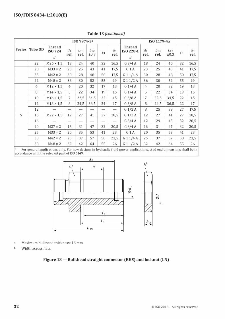
a Maximum bulkhead thickness: 16 mm.b Width across flats.
Figure 18 — Bulkhead straight connector (BHS) and locknut (LN)
Table 13 (continued)
32 © ISO 2018 – All rights reserved
ISO/FDIS 8434-1:2018(E)
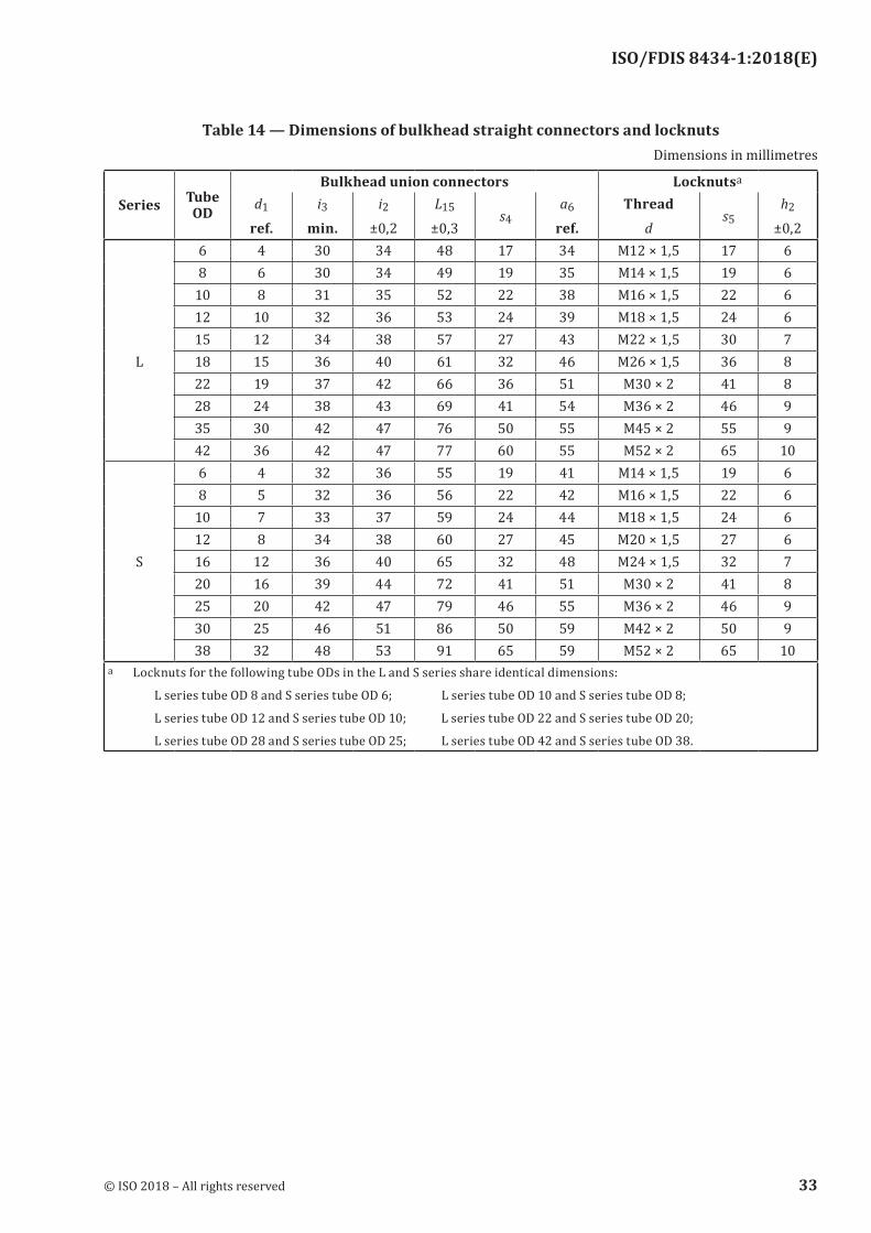
Table 14 — Dimensions of bulkhead straight connectors and locknutsDimensions in millimetres
Series Tube OD
Bulkhead union connectors Locknutsa
d1
ref.i3
min.i2
±0,2L15
±0,3s4
a6
ref.Thread
ds5
h2
±0,26 4 30 34 48 17 34 M12 × 1,5 17 68 6 30 34 49 19 35 M14 × 1,5 19 6
10 8 31 35 52 22 38 M16 × 1,5 22 612 10 32 36 53 24 39 M18 × 1,5 24 615 12 34 38 57 27 43 M22 × 1,5 30 7
L 18 15 36 40 61 32 46 M26 × 1,5 36 822 19 37 42 66 36 51 M30 × 2 41 828 24 38 43 69 41 54 M36 × 2 46 935 30 42 47 76 50 55 M45 × 2 55 942 36 42 47 77 60 55 M52 × 2 65 106 4 32 36 55 19 41 M14 × 1,5 19 68 5 32 36 56 22 42 M16 × 1,5 22 6
10 7 33 37 59 24 44 M18 × 1,5 24 612 8 34 38 60 27 45 M20 × 1,5 27 6
S 16 12 36 40 65 32 48 M24 × 1,5 32 720 16 39 44 72 41 51 M30 × 2 41 825 20 42 47 79 46 55 M36 × 2 46 930 25 46 51 86 50 59 M42 × 2 50 938 32 48 53 91 65 59 M52 × 2 65 10
a Locknuts for the following tube ODs in the L and S series share identical dimensions:
L series tube OD 8 and S series tube OD 6; L series tube OD 10 and S series tube OD 8;
L series tube OD 12 and S series tube OD 10; L series tube OD 22 and S series tube OD 20;
L series tube OD 28 and S series tube OD 25; L series tube OD 42 and S series tube OD 38.
© ISO 2018 – All rights reserved 33
ISO/FDIS 8434-1:2018(E)
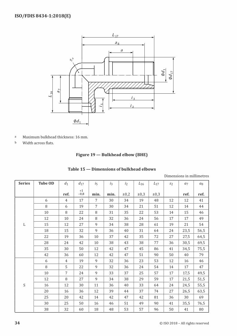
a Maximum bulkhead thickness: 16 mm.b Width across flats.
Figure 19 — Bulkhead elbow (BHE)
Table 15 — Dimensions of bulkhead elbowsDimensions in millimetres
Series Tube OD d1 d17 i5 i3 i2 L16 L17 s2 a7 a8
ref. −+0 8
1
, min. min. ±0,2 ±0,3 ±0,3 ref. ref.6 4 17 7 30 34 19 48 12 12 418 6 19 7 30 34 21 51 12 14 44
10 8 22 8 31 35 22 53 14 15 4612 10 24 8 32 36 24 56 17 17 49
L 15 12 27 9 34 38 28 61 19 21 5418 15 32 9 36 40 31 64 24 23,5 56,522 19 36 10 37 42 35 72 27 27,5 64,528 24 42 10 38 43 38 77 36 30,5 69,535 30 50 12 42 47 45 86 41 34,5 75,542 36 60 12 42 47 51 90 50 40 796 4 19 9 32 36 23 53 12 16 468 5 22 9 32 36 24 54 14 17 47
10 7 24 9 33 37 25 57 17 17,5 49,512 8 27 9 34 38 29 59 17 21,5 51,5
S 16 12 30 11 36 40 33 64 24 24,5 55,520 16 36 12 39 44 37 74 27 26,5 63,525 20 42 14 42 47 42 81 36 30 6930 25 50 16 46 51 49 90 41 35,5 76,538 32 60 18 48 53 57 96 50 41 80
34 © ISO 2018 – All rights reserved
ISO/FDIS 8434-1:2018(E)
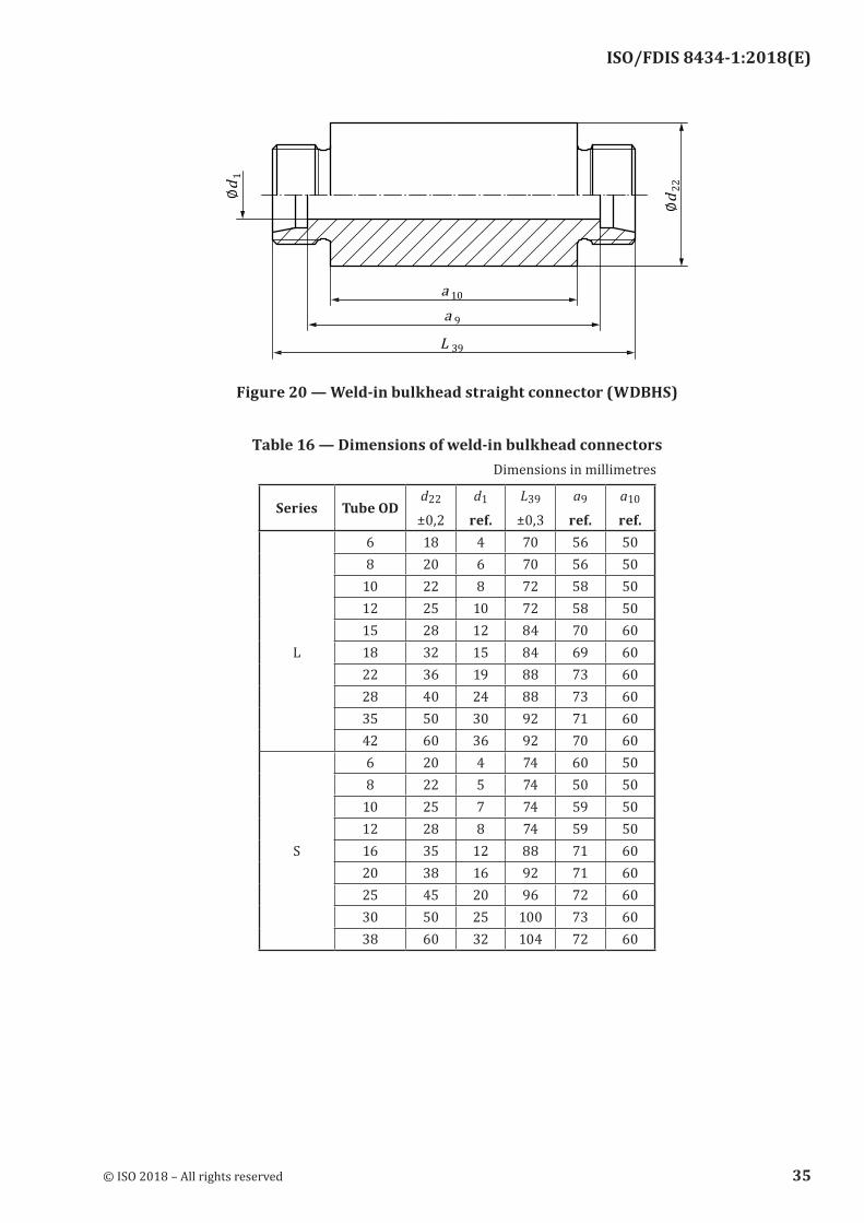
Figure 20 — Weld‑in bulkhead straight connector (WDBHS)
Table 16 — Dimensions of weld‑in bulkhead connectorsDimensions in millimetres
Series Tube ODd22
±0,2d1
ref.L39
±0,3a9
ref.a10
ref.6 18 4 70 56 508 20 6 70 56 50
10 22 8 72 58 5012 25 10 72 58 5015 28 12 84 70 60
L 18 32 15 84 69 6022 36 19 88 73 6028 40 24 88 73 6035 50 30 92 71 6042 60 36 92 70 606 20 4 74 60 508 22 5 74 50 50
10 25 7 74 59 5012 28 8 74 59 50
S 16 35 12 88 71 6020 38 16 92 71 6025 45 20 96 72 6030 50 25 100 73 6038 60 32 104 72 60
© ISO 2018 – All rights reserved 35
ISO/FDIS 8434-1:2018(E)
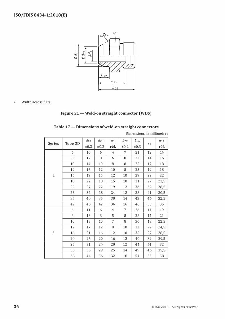
a Width across flats.
Figure 21 — Weld‑on straight connector (WDS)
Table 17 — Dimensions of weld‑on straight connectorsDimensions in millimetres
Series Tube ODd10
±0,2d23
±0,2d1
réf.L22
±0,2L26
±0,3s1
a11
réf.6 10 6 4 7 21 12 148 12 8 6 8 23 14 16
10 14 10 8 8 25 17 1812 16 12 10 8 25 19 18
L 15 19 15 12 10 29 22 2218 22 18 15 10 31 27 23,522 27 22 19 12 36 32 28,528 32 28 24 12 38 41 30,535 40 35 30 14 43 46 32,542 46 42 36 16 46 55 356 11 6 4 7 26 14 198 13 8 5 8 28 17 21
10 15 10 7 8 30 19 22,512 17 12 8 10 32 22 24,5
S 16 21 16 12 10 35 27 26,520 26 20 16 12 40 32 29,525 31 24 20 12 44 41 3230 36 29 25 14 49 46 35,538 44 36 32 16 54 55 38
36 © ISO 2018 – All rights reserved
ISO/FDIS 8434-1:2018(E)
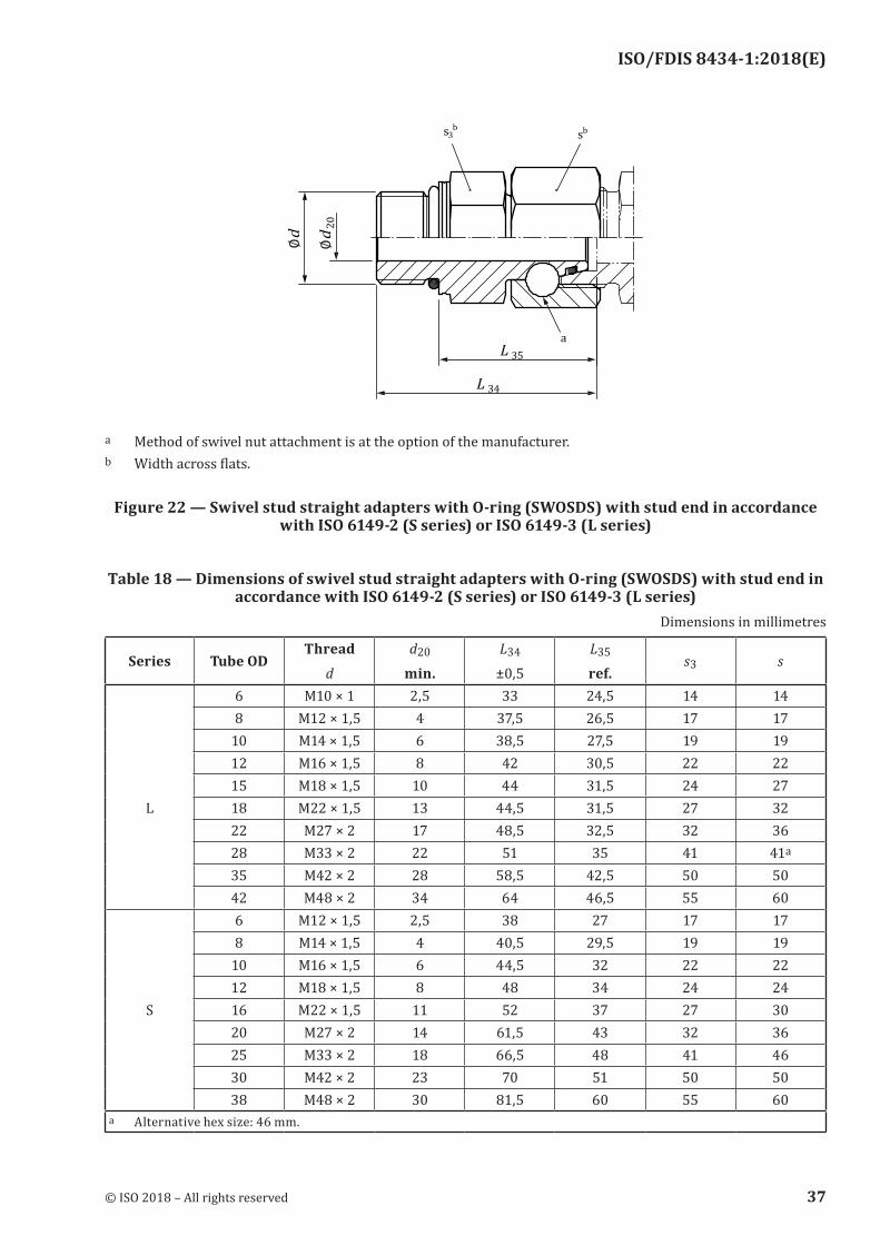
a Method of swivel nut attachment is at the option of the manufacturer.b Width across flats.
Figure 22 — Swivel stud straight adapters with O‑ring (SWOSDS) with stud end in accordance with ISO 6149-2 (S series) or ISO 6149-3 (L series)
Table 18 — Dimensions of swivel stud straight adapters with O‑ring (SWOSDS) with stud end in accordance with ISO 6149‑2 (S series) or ISO 6149‑3 (L series)
Dimensions in millimetres
Series Tube ODThread
d
d20
min.L34
±0,5L35
ref.s3 s
6 M10 × 1 2,5 33 24,5 14 148 M12 × 1,5 4 37,5 26,5 17 17
10 M14 × 1,5 6 38,5 27,5 19 1912 M16 × 1,5 8 42 30,5 22 2215 M18 × 1,5 10 44 31,5 24 27
L 18 M22 × 1,5 13 44,5 31,5 27 3222 M27 × 2 17 48,5 32,5 32 3628 M33 × 2 22 51 35 41 41a
35 M42 × 2 28 58,5 42,5 50 5042 M48 × 2 34 64 46,5 55 606 M12 × 1,5 2,5 38 27 17 178 M14 × 1,5 4 40,5 29,5 19 19
10 M16 × 1,5 6 44,5 32 22 2212 M18 × 1,5 8 48 34 24 24
S 16 M22 × 1,5 11 52 37 27 3020 M27 × 2 14 61,5 43 32 3625 M33 × 2 18 66,5 48 41 4630 M42 × 2 23 70 51 50 5038 M48 × 2 30 81,5 60 55 60
a Alternative hex size: 46 mm.
© ISO 2018 – All rights reserved 37
ISO/FDIS 8434-1:2018(E)
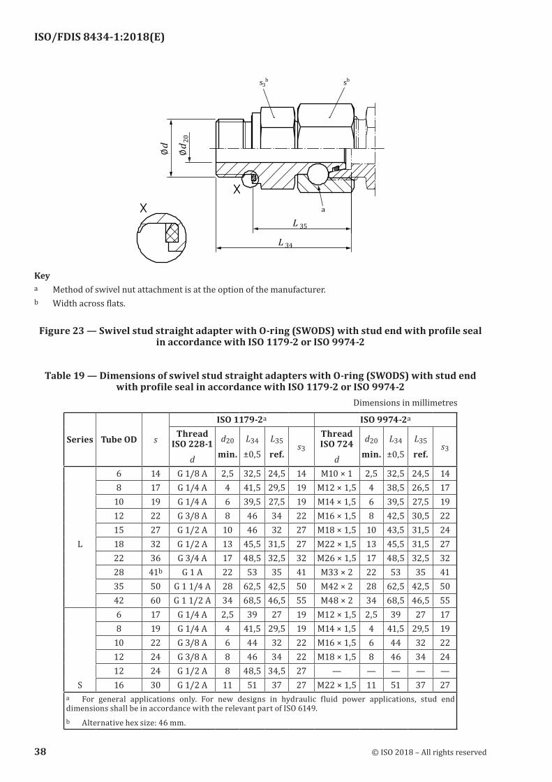
Keya Method of swivel nut attachment is at the option of the manufacturer.b Width across flats.
Figure 23 — Swivel stud straight adapter with O‑ring (SWODS) with stud end with profile seal in accordance with ISO 1179‑2 or ISO 9974‑2
Table 19 — Dimensions of swivel stud straight adapters with O‑ring (SWODS) with stud end with profile seal in accordance with ISO 1179‑2 or ISO 9974‑2
Dimensions in millimetres
Series Tube OD s
ISO 1179-2a ISO 9974-2a
Thread ISO 228-1
d
d20
min.L34
±0,5L35
ref.s3
Thread ISO 724
d
d20
min.L34
±0,5L35
ref.s3
6 14 G 1/8 A 2,5 32,5 24,5 14 M10 × 1 2,5 32,5 24,5 148 17 G 1/4 A 4 41,5 29,5 19 M12 × 1,5 4 38,5 26,5 17
10 19 G 1/4 A 6 39,5 27,5 19 M14 × 1,5 6 39,5 27,5 1912 22 G 3/8 A 8 46 34 22 M16 × 1,5 8 42,5 30,5 2215 27 G 1/2 A 10 46 32 27 M18 × 1,5 10 43,5 31,5 24
L 18 32 G 1/2 A 13 45,5 31,5 27 M22 × 1,5 13 45,5 31,5 2722 36 G 3/4 A 17 48,5 32,5 32 M26 × 1,5 17 48,5 32,5 3228 41b G 1 A 22 53 35 41 M33 × 2 22 53 35 4135 50 G 1 1/4 A 28 62,5 42,5 50 M42 × 2 28 62,5 42,5 5042 60 G 1 1/2 A 34 68,5 46,5 55 M48 × 2 34 68,5 46,5 556 17 G 1/4 A 2,5 39 27 19 M12 × 1,5 2,5 39 27 178 19 G 1/4 A 4 41,5 29,5 19 M14 × 1,5 4 41,5 29,5 19
10 22 G 3/8 A 6 44 32 22 M16 × 1,5 6 44 32 2212 24 G 3/8 A 8 46 34 22 M18 × 1,5 8 46 34 2412 24 G 1/2 A 8 48,5 34,5 27 — — — — —
S 16 30 G 1/2 A 11 51 37 27 M22 × 1,5 11 51 37 27a For general applications only. For new designs in hydraulic fluid power applications, stud end dimensions shall be in accordance with the relevant part of ISO 6149.b Alternative hex size: 46 mm.
38 © ISO 2018 – All rights reserved
ISO/FDIS 8434-1:2018(E)
Series Tube OD s
ISO 1179-2a ISO 9974-2a
Thread ISO 228-1
d
d20
min.L34
±0,5L35
ref.s3
Thread ISO 724
d
d20
min.L34
±0,5L35
ref.s3
16 30 G 3/4 A 11 55 39 32 — — — — —20 36 G 3/4 A 14 59 43 32 M27 × 2 14 59 43 3225 46 G 1 A 18 66 48 41 M33 × 2 18 66 48 4130 50 G 1 1/4 A 23 71 51 50 M42 × 2 23 71 51 5038 60 G 1 1/2 A 30 82 60 55 M48 × 2 30 82 60 55
a For general applications only. For new designs in hydraulic fluid power applications, stud end dimensions shall be in accordance with the relevant part of ISO 6149.b Alternative hex size: 46 mm.
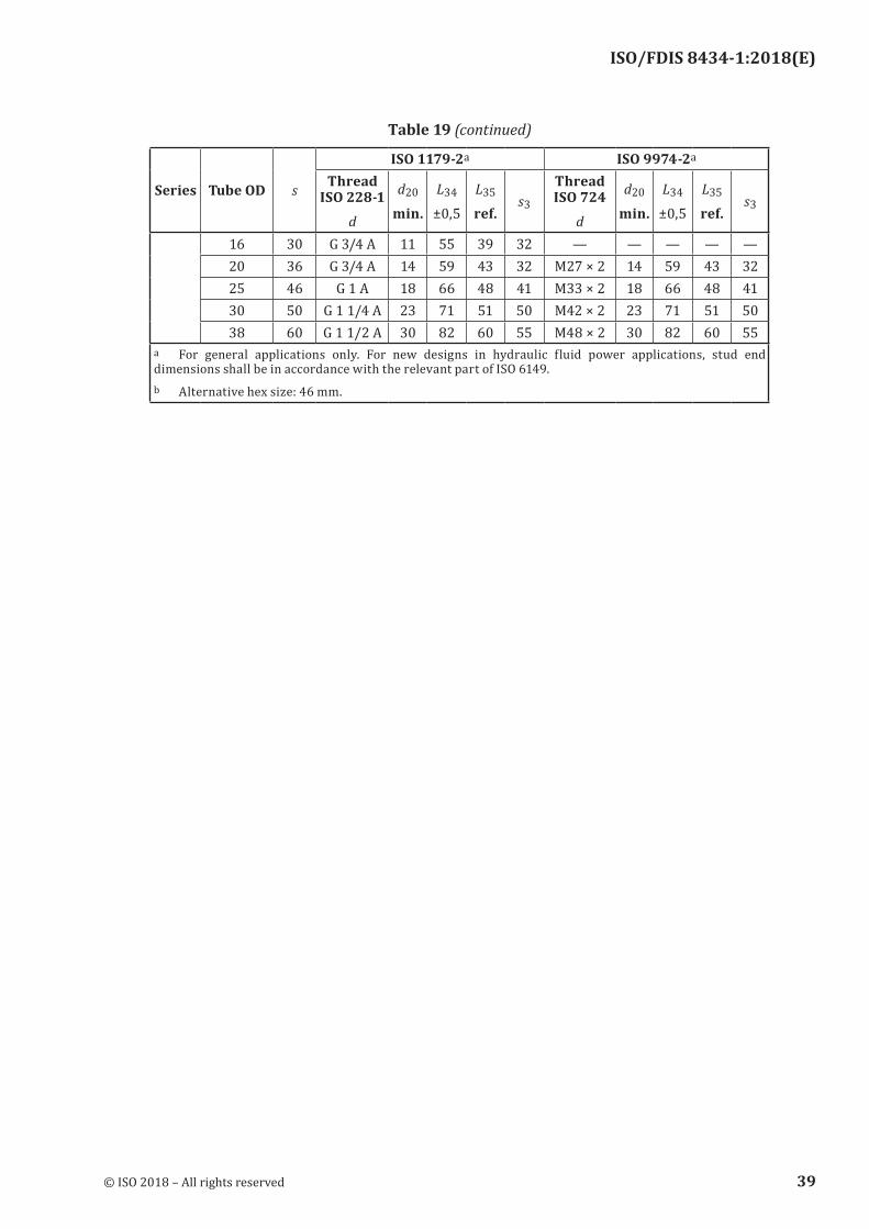
Table 19 (continued)
© ISO 2018 – All rights reserved 39
ISO/FDIS 8434-1:2018(E)
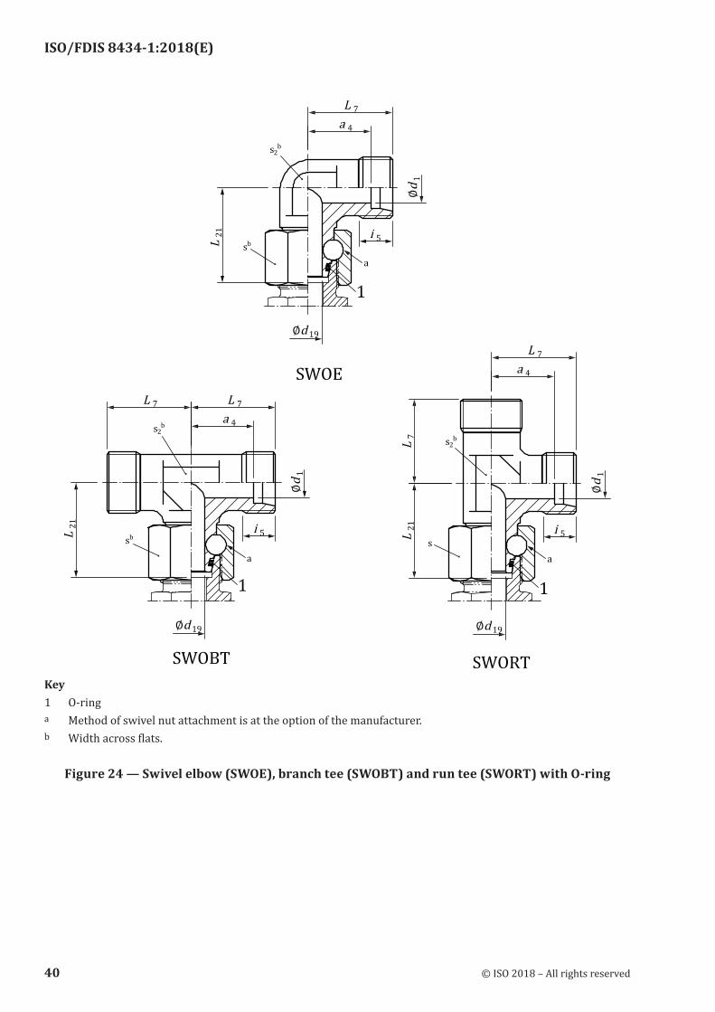
Key1 O-ringa Method of swivel nut attachment is at the option of the manufacturer.b Width across flats.
Figure 24 — Swivel elbow (SWOE), branch tee (SWOBT) and run tee (SWORT) with O‑ring
40 © ISO 2018 – All rights reserved
ISO/FDIS 8434-1:2018(E)
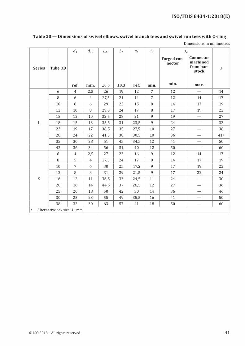
Table 20 — Dimensions of swivel elbows, swivel branch tees and swivel run tees with O‑ringDimensions in millimetres
Series Tube OD
d1
ref.
d19
min.
L21
±0,5
L7
±0,3
a4
ref.
i5
min.
s2
s
Forged con-nector
min.
Connector machined from bar-
stock
max.6 4 2,5 26 19 12 7 12 — 148 6 4 27,5 21 14 7 12 14 17
10 8 6 29 22 15 8 14 17 1912 10 8 29,5 24 17 8 17 19 2215 12 10 32,5 28 21 9 19 — 27
L 18 15 13 35,5 31 23,5 9 24 — 3222 19 17 38,5 35 27,5 10 27 — 3628 24 22 41,5 38 30,5 10 36 — 41a
35 30 28 51 45 34,5 12 41 — 5042 36 34 56 51 40 12 50 — 606 4 2,5 27 23 16 9 12 14 178 5 4 27,5 24 17 9 14 17 19
10 7 6 30 25 17,5 9 17 19 2212 8 8 31 29 21,5 9 17 22 24
S 16 12 11 36,5 33 24,5 11 24 — 3020 16 14 44,5 37 26,5 12 27 — 3625 20 18 50 42 30 14 36 — 4630 25 23 55 49 35,5 16 41 — 5038 32 30 63 57 41 18 50 — 60
a Alternative hex size: 46 mm.
© ISO 2018 – All rights reserved 41
ISO/FDIS 8434-1:2018(E)
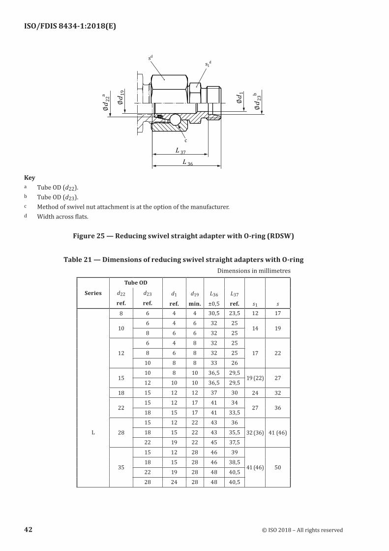
Keya Tube OD (d22).b Tube OD (d23).c Method of swivel nut attachment is at the option of the manufacturer.d Width across flats.
Figure 25 — Reducing swivel straight adapter with O‑ring (RDSW)
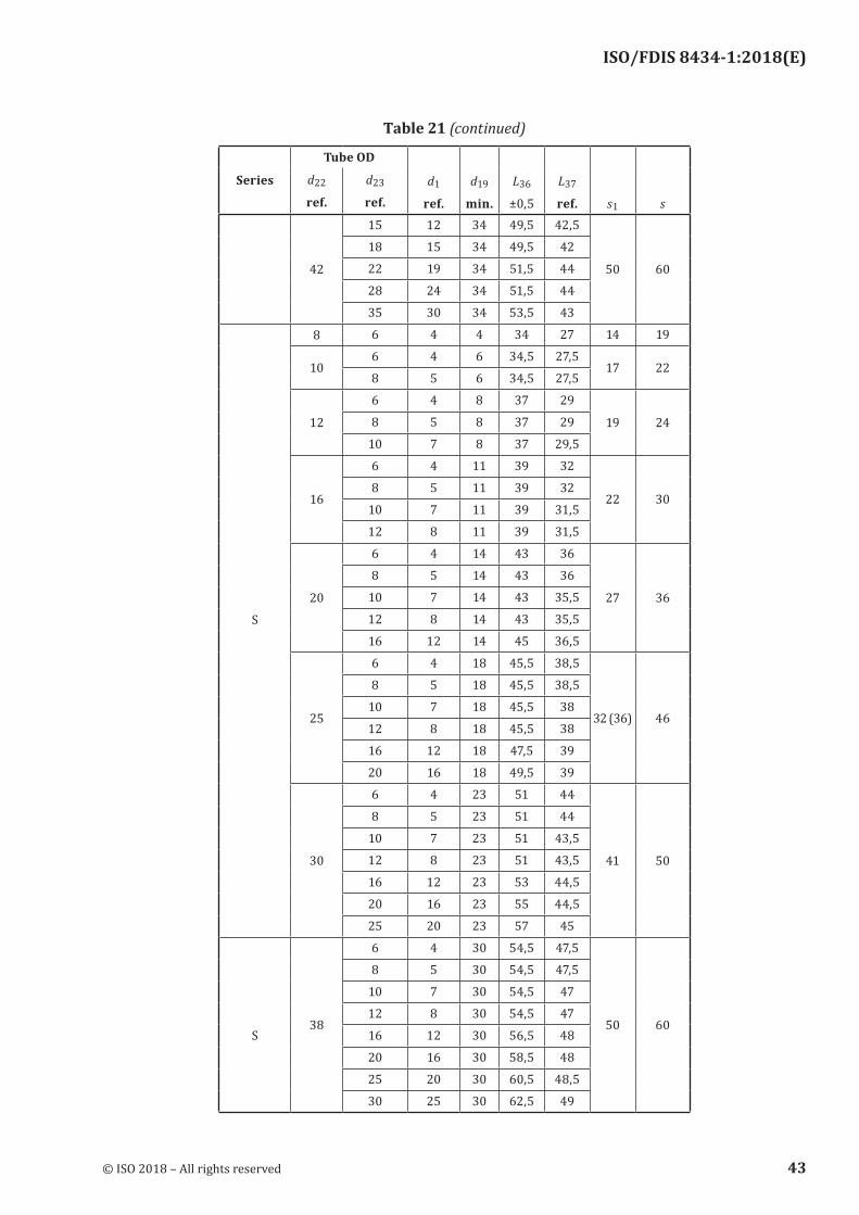
Table 21 — Dimensions of reducing swivel straight adapters with O‑ringDimensions in millimetres
Series
Tube OD
d1
ref.
d19
min.
L36
±0,5
L37
ref. s1 s
d22
ref.
d23
ref.
8 6 4 4 30,5 23,5 12 17
106 4 6 32 25
14 198 6 6 32 25
12
6 4 8 32 25
17 228 6 8 32 25
10 8 8 33 26
1510 8 10 36,5 29,5
19 (22) 2712 10 10 36,5 29,5
18 15 12 12 37 30 24 32
2215 12 17 41 34
27 3618 15 17 41 33,5
28
15 12 22 43 36
32 (36) 41 (46)L 18 15 22 43 35,5
22 19 22 45 37,5
35
15 12 28 46 39
41 (46) 5018 15 28 46 38,5
22 19 28 48 40,5
28 24 28 48 40,5
42 © ISO 2018 – All rights reserved
ISO/FDIS 8434-1:2018(E)
Series
Tube OD
d1
ref.
d19
min.
L36
±0,5
L37
ref. s1 s
d22
ref.
d23
ref.
42
15 12 34 49,5 42,5
50 60
18 15 34 49,5 42
22 19 34 51,5 44
28 24 34 51,5 44
35 30 34 53,5 43
8 6 4 4 34 27 14 19
106 4 6 34,5 27,5
17 228 5 6 34,5 27,5
12
6 4 8 37 29
19 248 5 8 37 29
10 7 8 37 29,5
16
6 4 11 39 32
22 308 5 11 39 32
10 7 11 39 31,5
12 8 11 39 31,5
20
6 4 14 43 36
27 36
8 5 14 43 36
10 7 14 43 35,5
S 12 8 14 43 35,5
16 12 14 45 36,5
25
6 4 18 45,5 38,5
32 (36) 46
8 5 18 45,5 38,5
10 7 18 45,5 38
12 8 18 45,5 38
16 12 18 47,5 39
20 16 18 49,5 39
30
6 4 23 51 44
41 50
8 5 23 51 44
10 7 23 51 43,5
12 8 23 51 43,5
16 12 23 53 44,5
20 16 23 55 44,5
25 20 23 57 45
38
6 4 30 54,5 47,5
50 60
8 5 30 54,5 47,5
10 7 30 54,5 47
12 8 30 54,5 47
S 16 12 30 56,5 48
20 16 30 58,5 48
25 20 30 60,5 48,5
30 25 30 62,5 49
Table 21 (continued)
© ISO 2018 – All rights reserved 43
ISO/FDIS 8434-1:2018(E)
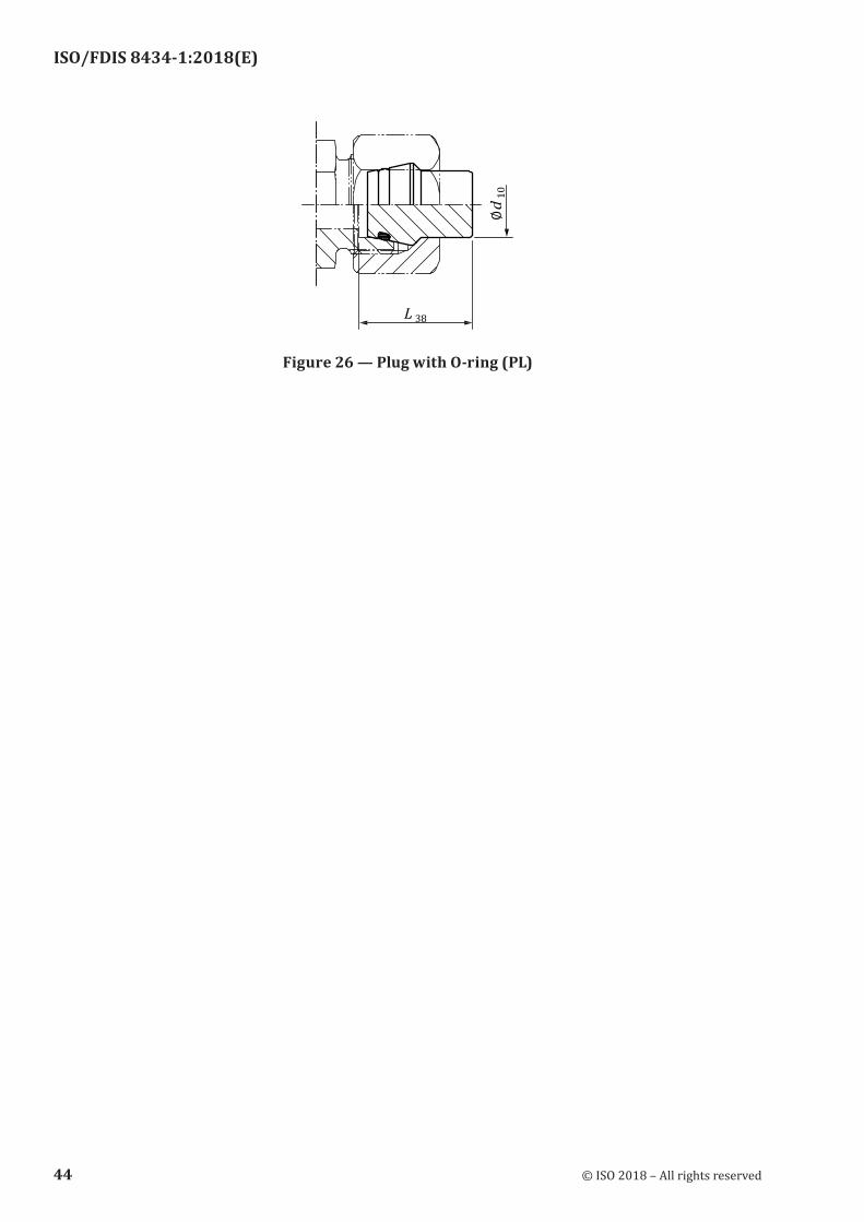
Figure 26 — Plug with O‑ring (PL)
44 © ISO 2018 – All rights reserved
ISO/FDIS 8434-1:2018(E)
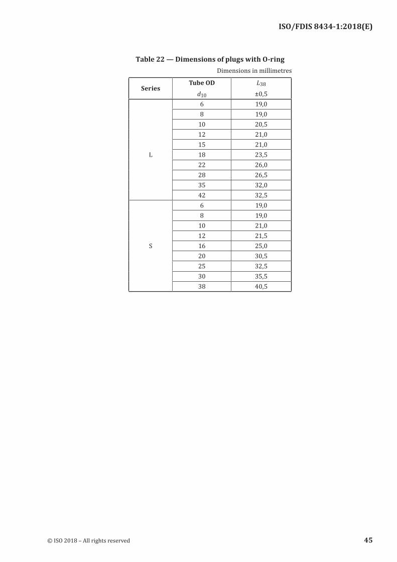
Table 22 — Dimensions of plugs with O‑ringDimensions in millimetres
SeriesTube OD
d10
L38
±0,56 19,08 19,0
10 20,512 21,015 21,0
L 18 23,522 26,028 26,535 32,042 32,56 19,08 19,0
10 21,012 21,5
S 16 25,020 30,525 32,530 35,538 40,5
© ISO 2018 – All rights reserved 45
ISO/FDIS 8434-1:2018(E)
Annex A (normative)
Assembly instructions for 24° cone connectors using cutting ring
conforming to ISO 8434‑1
A.1 General
NOTICE: Best practice regarding reliability and safety is achieved by pre‑assembling the cutting rings using machines. For machines suitable for this operation, along with tools and setup parameters, the connector manufacturer should be consulted.
A.2 Cutting ring direct assembly into coupling body
Follow the instructions of Table A.2 unless otherwise specified by the manufacturer.
46 © ISO 2018 – All rights reserved
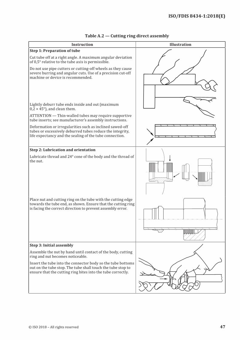
ISO/FDIS 8434-1:2018(E)
Table A.2 — Cutting ring direct assembly
Instruction IllustrationStep 1: Preparation of tubeCut tube off at a right angle. A maximum angular deviation of 0,5° relative to the tube axis is permissible.Do not use pipe cutters or cutting-off wheels as they cause severe burring and angular cuts. Use of a precision cut-off machine or device is recommended. Lightly deburr tube ends inside and out (maximum 0,2 × 45°), and clean them.ATTENTION — Thin-walled tubes may require supportive tube inserts; see manufacturer’s assembly instructions.Deformation or irregularities such as inclined sawed-off tubes or excessively deburred tubes reduce the integrity, life expectancy and the sealing of the tube connection.
Step 2: Lubrication and orientationLubricate thread and 24° cone of the body and the thread of the nut.
Place nut and cutting ring on the tube with the cutting edge towards the tube end, as shown. Ensure that the cutting ring is facing the correct direction to prevent assembly error.
Step 3: Initial assemblyAssemble the nut by hand until contact of the body, cutting ring and nut becomes noticeable.Insert the tube into the connector body so the tube bottoms out on the tube stop. The tube shall touch the tube stop to ensure that the cutting ring bites into the tube correctly.
© ISO 2018 – All rights reserved 47
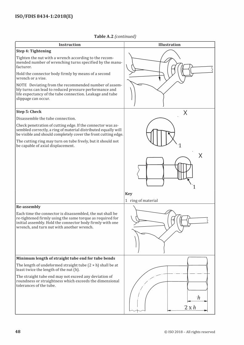
ISO/FDIS 8434-1:2018(E)
Instruction IllustrationStep 4: TighteningTighten the nut with a wrench according to the recom-mended number of wrenching turns specified by the manu-facturer.Hold the connector body firmly by means of a second wrench or a vise.NOTE Deviating from the recommended number of assem-bly turns can lead to reduced pressure performance and life expectancy of the tube connection. Leakage and tube slippage can occur.
Step 5: CheckDisassemble the tube connection.Check penetration of cutting edge. If the connector was as-sembled correctly, a ring of material distributed equally will be visible and should completely cover the front cutting edge.The cutting ring may turn on tube freely, but it should not be capable of axial displacement.
Key1 ring of material
Re-assemblyEach time the connector is disassembled, the nut shall be re-tightened firmly using the same torque as required for initial assembly. Hold the connector body firmly with one wrench, and turn nut with another wrench.
Minimum length of straight tube end for tube bendsThe length of undeformed straight tube (2 × h) shall be at least twice the length of the nut (h).The straight tube end may not exceed any deviation of roundness or straightness which exceeds the dimensional tolerances of the tube.
Table A.2 (continued)
48 © ISO 2018 – All rights reserved
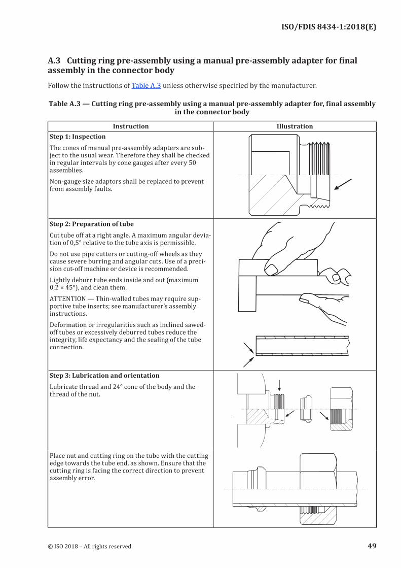
ISO/FDIS 8434-1:2018(E)
A.3 Cutting ring pre‑assembly using a manual pre‑assembly adapter for final assembly in the connector body
Follow the instructions of Table A.3 unless otherwise specified by the manufacturer.
Table A.3 — Cutting ring pre‑assembly using a manual pre‑assembly adapter for, final assembly in the connector body
Instruction IllustrationStep 1: InspectionThe cones of manual pre-assembly adapters are sub-ject to the usual wear. Therefore they shall be checked in regular intervals by cone gauges after every 50 assemblies.Non-gauge size adaptors shall be replaced to prevent from assembly faults.
Step 2: Preparation of tubeCut tube off at a right angle. A maximum angular devia-tion of 0,5° relative to the tube axis is permissible.Do not use pipe cutters or cutting-off wheels as they cause severe burring and angular cuts. Use of a preci-sion cut-off machine or device is recommended.Lightly deburr tube ends inside and out (maximum 0,2 × 45°), and clean them.ATTENTION — Thin-walled tubes may require sup-portive tube inserts; see manufacturer’s assembly instructions.Deformation or irregularities such as inclined sawed-off tubes or excessively deburred tubes reduce the integrity, life expectancy and the sealing of the tube connection.
Step 3: Lubrication and orientationLubricate thread and 24° cone of the body and the thread of the nut.
Place nut and cutting ring on the tube with the cutting edge towards the tube end, as shown. Ensure that the cutting ring is facing the correct direction to prevent assembly error.
© ISO 2018 – All rights reserved 49
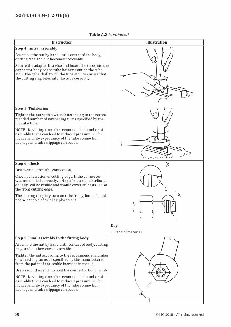
ISO/FDIS 8434-1:2018(E)
Instruction IllustrationStep 4: Initial assemblyAssemble the nut by hand until contact of the body, cutting ring and nut becomes noticeable.Secure the adapter in a vise and insert the tube into the connector body so the tube bottoms out on the tube stop. The tube shall touch the tube stop to ensure that the cutting ring bites into the tube correctly.
Step 5: TighteningTighten the nut with a wrench according to the recom-mended number of wrenching turns specified by the manufacturer.NOTE Deviating from the recommended number of assembly turns can lead to reduced pressure perfor-mance and life expectancy of the tube connection. Leakage and tube slippage can occur.
Step 6: CheckDisassemble the tube connection.Check penetration of cutting edge. If the connector was assembled correctly, a ring of material distributed equally will be visible and should cover at least 80% of the front cutting edge.The cutting ring may turn on tube freely, but it should not be capable of axial displacement.
Key1 ring of material
Step 7: Final assembly in the fitting bodyAssemble the nut by hand until contact of body, cutting ring, and nut becomes noticeable.Tighten the nut according to the recommended number of wrenching turns as specified by the manufacturer from the point of noticeable increase in torque.Use a second wrench to hold the connector body firmly.NOTE Deviating from the recommended number of assembly turns can lead to reduced pressure perfor-mance and life expectancy of the tube connection. Leakage and tube slippage can occur.
Table A.3 (continued)
50 © ISO 2018 – All rights reserved
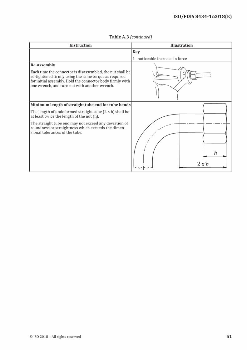
ISO/FDIS 8434-1:2018(E)
Instruction IllustrationKey1 noticeable increase in force
Re-assemblyEach time the connector is disassembled, the nut shall be re-tightened firmly using the same torque as required for initial assembly. Hold the connector body firmly with one wrench, and turn nut with another wrench.
Minimum length of straight tube end for tube bendsThe length of undeformed straight tube (2 × h) shall be at least twice the length of the nut (h).The straight tube end may not exceed any deviation of roundness or straightness which exceeds the dimen-sional tolerances of the tube.
Table A.3 (continued)
© ISO 2018 – All rights reserved 51
ISO/FDIS 8434-1:2018(E)
Bibliography
[1] ISO 228-2, Pipe threads where pressure-tight joints are not made on the threads — Part 2: Verification by means of limit gauges
[2] ISO 286-11), Geometrical product specifications (GPS) — ISO code system for tolerances on linear sizes — Part 1: Basis of tolerances, deviations and fits)
[3] ISO 286-2, Geometrical product specifications (GPS) — ISO code system for tolerances on linear sizes — Part 2: Tables of standard tolerance classes and limit deviations for holes and shafts
[4] ISO 1179-3, Connections for general use and fluid power — Ports and stud ends with ISO 228-1 threads with elastomeric or metal-to-metal sealing — Part 3: Light-duty (L series) stud ends with sealing by O-ring with retaining ring (types G and H)
[5] ISO 4397, Fluid power connectors and associated components — Nominal outside diameters of tubes and nominal hose sizes
[6] ISO 4399, Fluid power systems and components — Connectors and associated components — Nominal pressures
[7] ISO 10763, Hydraulic fluid power — Plain-end, seamless and welded precision steel tubes — Dimensions and nominal working pressures
[8] ISO 12151-2, Connections for hydraulic fluid power and general use — Hose fittings — Part 2: Hose fittings with ISO 8434-1 and ISO 8434-4 24 degree cone connector ends with O-rings
1) Under revision.
52 © ISO 2018 – All rights reserved


ISO/FDIS 8434-1:2018(E)
© ISO 2018 – All rights reserved
ICS 23.100.40Price based on 52 pages