film annotation system space experiment · experiment (idge) film annotation system (fas). this...
TRANSCRIPT
NASA Contractor Report No. 185114
Film Annotation System For A Space Experiment
MILETUS ASSOCIATES, INC. Albuqueque, New Mexico
July 1989
Prepared for National h n a u t i c s and Space Administration Lawis Reeearda Center Contract NAS 3-25055
~ n a s a - c ~ - i a s i I 4) F x n ANNOTATION SYSTEH FOE B SPACE EXPEBIHENT [ M i l e t u s A s s o c i a t e s ) 124 p CSCL 14E
Uaclas 0224572
https://ntrs.nasa.gov/search.jsp?R=19890017781 2020-05-08T22:41:55+00:00Z
Table . of Contents
Paqe No . 1.) Summary ............................................. 1-1
2.) Introduction ........................................ 2-1
3.) Camera Modifications ................................ 3-1
4.) FAS Hardware Description ............................ 4-1
4.0 General ....................................... 4-1 4.1 Microprocessor Support Circuitry .............. 4-1 4.2 Real Time Clock ............................... 4-1 4.3 Camera Interface Circuitry .................... 4-2 4.4 STD BUSS Interface ............................ 4-2
4.4.1 FAS Status Code to STD ................. 4-3 4.4.2 FAS Interval Warning to STD ............ 4-4 4.4.3 FAS Photo Confirmation Bit to STD ...... 4-5 4.4.4 Data and Ready Ports ................... 4-5
4.5 Communication Protocol ........................ 4-5
5.) FAS Software Description ............................ 5-1
5.0 5.1 5.2 5.3 5.4 5.5 5.6 5.7
5.8 5.9 5.10 5.11 5.12 5.13 5.14 5.15 5.16 5.17 5.18 5.19 5.20 5.21 5.22
General ....................................... 5-1
STD CPU Camera Trigger Command ................ 5-1 FAS CPU Reset Command ......................... 5-2 Read Hardware Frame Counter ................... 5-2 Reset Hardware Frame Counter .................. 5-2 Set FAS Annotation Mode ....................... 5-2 Send Last Photo "X" Switch Data to STD BUSS CPU .................................. 5-3 Receive Text From STD BUSS CPU ................ 5-3
FAS CPU Camera Trigger Enable/Disable ......... 5-1
Set GMT Time .................................. 5-3 'IGo" Command To Start Clock ................... 5-4 Set Intervalometer Parameters ................. 5-4
Command to Start Photo Sequence .......... 5-4 FAS Status Code to STD ........................ 5-4 Cancel Current Photo Sequence ................. 5-5 Interval Pre-Warning Flag ..................... 5-5 Photo Confirmation to STD ..................... 5-5 Photo Count This Sequence ..................... 5-6 Perform FAS Communication Port Test ........... 5-6 Request FAS Hardware Self Test ................. 5-6 Report Annotation Mode to STD ................. 5-6 Report Time Left to Next Scheduled Photo ...... 5-7 Set Software Frame Counter .................... 5-7
0 Go 11
PRECEDiNG PAGE BLANK MOT FILMED
iii
Table of Contents. cont'd . Page No .
Appendix A . Test Procedure ................................ A-1
Table of Contents ............................. A-2
Appendix B . PASCAL Program Listing ........................ B-1
Table of Contents ............................. B-2 STD PASCAL Procedures ......................... B-3 STD PASCAL TEST Program ....................... B-45
Appendix C . Figures ....................................... C-1
Table of Contents ............................. C-2 Figure 1 . FAS Card Block Diagram ............ C-3 Figure 2 . FAS Camera Interface Diagram ...... C-4
Figure 5 . Component Side of P.C. Board ...... C-7 Figure 6 . Solder Side of P.C. Board ......... C-7 Figure 7 . Test Set Up ....................... C-8
Figure 9 . Nikon F3 Front Cable Attachment ... C-9 Figure 10 . Nikon F3 Rear Cable Attachment .... C-9 Figure 11 . Nikon F3 Data Mask ................ C-10
Figure 3 . STD to FAS Communication Diagram .. C-5 Figure 4 . FAS to STD Communication Diagram .. C-6
Figure 8 . Nikon F3 Camera (Front View) ...... C-8
Figure 12 . RHA ............................... C-10
Appendix D . Drawings ...................................... D-1
Cable Drawing. #3895 Schematic Drawing FAS Card. #3964 Assembly Drawing FAS Card. #3964
Appendix E . Acronym Definitions ........................... E-1
iV
Section 1 Summarv
The following document has been prepared to provide the user with operating instructions for the Isothermal Dendritic Growth Experiment (IDGE) Film Annotation System (FAS). This annotation system is a microprocessor interface to a modified 35mm Nikon camera.
This microprocessor system has been manufactured on a single STD BUSS interface card. The interface card has been designed in such a way as to allow it to be used in either a stand alone application with minimum features or installed in an STD computer with maximum features available.
If the FAS card is installed in an STD computer system it has the ability to take commands from and communicate status information to the STD computer. If the FAS card is set up in a stand alone configuration, it will print time (starting from zero), day (0-9), camera ID (0-3), and frame count (0 -255) .
The Nikon camera has been modified to print a single row of up to 28 5x7 dot matrix characters across the bottom of the 35mm frame. A single bar of seven LEDs and coherent glass fiber bundle has been installed in the pressure plate of the film back to accomplish this annotation. In addition, an optical encoder has been installed in the motor driver to provide column demands to the FAS card.
1-1
Section 2 Introduction
Miletus has designed a FAS for use by NASA on the Isothermal ! Dendritic Growth Experiment (IDGE). I i
The systems capabilities include operation as a manual controller of a 35mm camera under the direction of the main CPU, controlling the STD BUSS, and operation as an intelligent intervalometer precisely controlling the photo taking sequence. In either case, all photos are annotated with alpha-numeric data including GMT (to 0.01 seconds resolution), camera ID number, frame count and text data derived from the STD BUSS CPU. The system consists of three parts:
. ) The Camera Modifications to add an LED printing matrix and an optical encoder to detect film motion.
. ) An intelligent STD BUSS peripheral card providing an interface between the CPU controlling the STD BUSS and the camera itself.
. ) High level language, (Turbo Pascal) software subroutines, (source code) to implement all functions from within the main IDGE software.
Each of these items is discussed in detail in the following sections.
2-1
Section 3 Camera Modifications
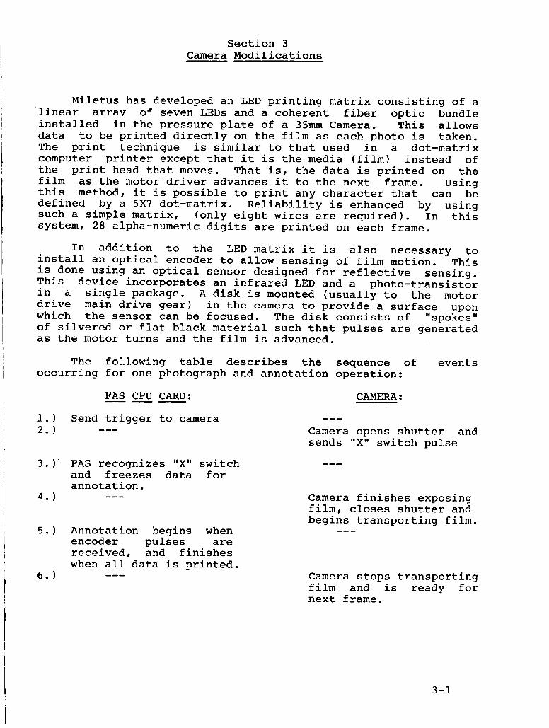
Miletus has developed an LED printing matrix consisting of a linear array of seven LEDs and a coherent fiber optic bundle installed in the pressure plate of a 35mm Camera. This allows data to be printed directly on the film as each photo is taken. The print technique is similar to that used in a dot-matrix computer printer except that it is the media (film) instead of the print head that moves. That is, the data is printed on the film as the motor driver advances it to the next frame. Using this method, it is possible to print any character that can be defined by a 5x7 dot-matrix. Reliability is enhanced by using such a simple matrix, (only eight wires are required). In this system, 28 alpha-numeric digits are printed on each frame.
In addition to the LED matrix it is also necessary to install an optical encoder to allow sensing of film motion. This is done using an optical sensor designed for reflective sensing. This device incorporates an infrared LED and a photo-transistor in a single package. A disk is mounted (usually to the motor drive main drive gear) in the camera to provide a surface upon which the sensor can be focused. The disk consists of llspokes" of silvered or flat black material such that pulses are generated as the motor turns and the film is advanced.
The following table describes the sequence of events occurring for one photograph and annotation operation:
FAS CPU CARD: --- Send trigger to camera ---
FAS recognizes "X" switch and freezes data for annotation. ---
Annotation begins when encoder pulses are received, and finishes when all data is printed. ---
--- Camera opens shutter and sends "X" switch pulse
---
Camera finishes exposing film, closes shutter and begins transporting film. ---
Camera stops transporting film and is ready for next frame.
3-1
Miletus has performed modifications of this nature to many different models of 35mm SLR Cameras while constantly aiming to avoid interference with either the electro-mechanical operation of the camera or the photo/optical capabilities. Since a non- contact motion sensor is used there is no affect on the mechanical operation of the camera. Also, since the LED printing matrix is independent of the camera shutter and lens the camera/lens do the LED intensity settings affect the camera.
settings have no effect on the LED intensity nor
Note: Under normal operation the FAS CPU Card acts as an intervalometer and, as such, is the primary source of camera trigger pulses. However, the camera may also be triggered by STD CPU or by the trigger on the camera itself. Consequently, the FAS which source of triggering is utilized. However, a cable waving change must be made to enable annotation when triggering the camera with its own shutter release control. This change involves removing the wire from J3 pin 12 and connecting it to J3 pin 19.
Card has been designed to annotate the film no matter
Note: If the FAS card is utilized in the standalone mode, jumper W1 must be connected to +5v. See Appendix D, drawing #3594.
3-2

Section 4 FAS Hardware Description
4 .0 General
Each FAS card contains all the STD BUSS communication capability, the data storage and time keeping functions, and the camera interface and control circuitry required to annotate one 35mm SLR camera under the control of the STD BUSS CPU.
The hardware consists of the following parts:
a) Microprocessor and support circuitry (NSC800 microprocessor) b) Real Time Clock (RTC) and crystal oscillator (ICM 7170) c) Camera interface and control circuitry (PAL Device) d) STD BUSS Interface and decoding logic (PAL Device)
4.1 Microprocessor Support Circuitry
The microprocessor and support circuitry consists of an eight bit CPU with 2K bytes of RAM and 8K bytes of EPROM. Erasable Programmable Logic Devices, (EPLD) are used to implement the necessary memory and 1/0 decoding functions required to operate the CPU. A hardware reset of the FAS CPU is available to the STD BUSS CPU by writing to a dedicated STD BUSS 1/0 address. Additionally, a watchdog timer is provided to initiate a FAS CPU reset should certain critical 1/0 operations fail to be detected within a certain allotted amount of time.
4 . 2 Real Time Clock (RTC) -- The RTC has a resolution of 0.01 second and uses a standard
crystal oscillator with a trimmer capacitor to adjust the accuracy. Using this trimmer the oscillator is set to the exact desired frequency (within the accuracy of our measuring equipment; +1/2 PPM) at the operating temperature to be used. The expectez frequency deviation should be less than +10 PPM over the range (30 degrees C +lo) To maintain a drift of- under two seconds per day only requrres an accuracy of - +23 PPM. is also settable from the STD BUSS only.
The clock
Upon power up, the RTC is loaded with all zeros and starts counting from there. It could be possible to use this feature as an elapsed time counter for use on other projects at a later date.
The ones of days are maintained by the FAS CPU. Upon power up the ones of days are set to zero and may be set to a value between 0 and 9 through the use of the STD CPU.
4-1

4.3 Camera Interface Circuitry
The camera interface circuitry allows the FAS CPU to trigger the camera, take a picture, detect an "X" switch closure from the camera, and (using the pulses provided by the optical encoder installed in the camera motor driver), annotates the film. The FAS circuitry allows the LED matrix intensity to be adjusted for proper exposure. This is accomplished using wire jumpers that can easily be changed in the field.
Additionally, this circuitry contains a hardware and software frame counter. The hardware frame counter may only be accessed by STD BUSS CPU. The software frame counter, however, is accessed by both the FAS CPU and the STD CPU. This feature ensures that the current frame count contained in the hardware frame counter cannot be disturbed by the FAS CPU should a malfunction occur. The hardware frame counter may be reset to zero by the STD CPU. It should be noted that the hardware frame count is used for reference only and the software frame count is printed on the film.
The camera may be triggered by the STD BUSS CPU or the FAS CPU; the STD BUSS CPU may disable the FAS CPU from performing this function. This allows the STD BUSS CPU to take over camera control and detect a problem on the FAS CPU Board.
The "X" switch is de-bounced for detection and used by the FAS CPU to freeze data at the time the film is exposed. The LED Head will then print this data as the film is advanced. This signal is also provided as an output to the IDGE system flash unit.
4 . 4 STD BUSS Interface -- The STD BUSS interface decoding is performed using an EPLD
in order to minimize board surface area used for this function. Two "types" of STD BUSS ports exist on the FAS Board, those that are independent of the FAS CPU and those used for control and communication of the FAS CPU by the STD BUSS CPU.
The BUSS ports independent of the FAS CPU consists of the following:
- FAS CPU HARD RESET (Write 00 to Port 108H) - HARDWARE FRAME COUNTER RESET (Write 02 to Port 108H) - READ HARDWARE FRAME COUNTER (Read from 107H) - STD BUSS TRIGGER TO CAMERA (Write 0 4 to 108H) - FAS CPU CAMERA TRIGGER ENABLE/DISABLE (Write 08 to 108H)
4-2
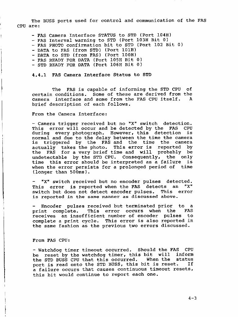
The BUSS ports used for control and communication of the FAS CPU are:
- FAS Camera Interface STATUS to STD (Port 104H) - FAS Interval warning to STD (Port 103H Bit 0) - FAS PHOTO confirmation bit to STD (Port 102 Bit 0) - DATA to FAS (from STD) (Port 101H) - DATA to STD (from FAS) (Port 100H) - FAS READY FOR DATA (Port 105H Bit 0) - STD READY FOR DATA (Port 106H Bit 0) 4 . 4 . 1 FAS Camera Interface Status to STD
The FAS is c'apable of informing the STD CPU of certain conditions. Some of these are derived from the camera interface and some from the FAS CPU itself. A brief description of each follows,
From the Camera Interface:
- Camera trigger received but no "X" switch detection. This error will occur and be detected by the FAS CPU during every photograph. However, this detection is normal and due to the delay between the time the camera is triggered by the FAS and the time the camera actually takes the photo. This error is reported by the FAS for a very brief time and will probably be undetectable by the STD CPU, Consequently, the only time this error should be interpreted as a failure is when the error persists for a prolonged period of time (longer than 500ms).
- "X" switch received but no encoder pulses detected. This error is reported when the FAS detects an "X" switch but does not detect encoder pulses. This error is reported in the same manner as discussed above.
- Encoder pulses received but terminated prior to a print complete. This error occurs when the FAS receives an insufficient number of encoder pulses to complete a print cycle. This error is also reported in the same fashion as the previous two errors discussed.
From FAS CPU:
- Watchdog timer timeout occurred. Should the FAS CPU be reset by the watchdog timer, this bit will inform the STD BUSS CPU that this occurred, When the status port is read onto the STD BUSS, this bit is reset. If a failure occurs that causes continuous timeout resets, this bit would continue to report each one.
4 - 3
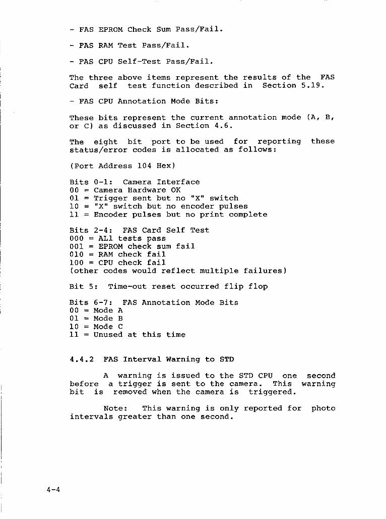
- FAS EPROM Check Sum Pass/Fail.
- FAS RAM Test Pass/Fail. - FAS CPU Self-Test Pass/Fail.
The three above items represent the results of the FAS Card self test function described in Section 5.19.
- FAS CPU Annotation Mode Bits:
These bits represent the current annotation mode (A, B, or C) as discussed in Section 4.6.
The eight bit port to be used for reporting these status/error codes is allocated as follows:
(Port Address 104 Hex)
Bits 0-1: Camera Interface 00 = Camera Hardware OK 01 = Trigger sent but no "X" switch 10 = "X" switch but no encoder pulses 11 = Encoder pulses but no print complete
Bits 2-4: FAS Card Self Test 000 = AL1 tests pass 001 = EPROM check sum fail 010 = RAM check fail 100 = CPU check fail (other codes would reflect multiple failures)
Bit 5: Time-out reset occurred flip flop
Bits 6-7: FAS Annotation Mode Bits 00 = Mode A 01 = Mode B 10 = Mode C 11 = Unused at this time
4 . 4 . 2 FAS Interval Warning to STD
A warning is issued to the STD CPU one second before a trigger is sent to the camera. This warning bit is removed when the camera is triggered.
Note: This warning is only reported for photo intervals greater than one second.
4-4
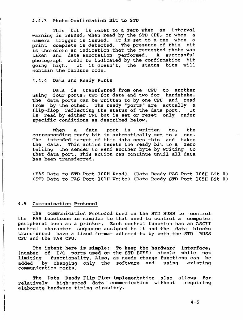
4 . 4 . 3 Photo Confirmation Bit to STD
This bit is reset to a zero when an interval warning is issued, when read by the STD CPU, or when a camera trigger is issued, It is set to a one when a print complete is detected. The presence of this bit is therefore an indication that the requested photo was taken and data annotation performed. A successful photograph would be indicated by the confirmation bit going high. If it doesn't, the status bits will contain the failure code.
4 . 4 . 4 Data and Ready Ports
Data is transferred from one CPU to another using four ports, two for data and two for handshake, The data ports can be written to by one CPU and read from by the other, The ready "ports" are actually a flip-flop reflecting the status of the data port, It is read by either CPU but is set or reset only under specific conditions as described below.
When a data port is written to, the corresponding ready bit is automatically set to a one. The intended target of this data sees this and takes the data. This action resets the ready bit to a zero telling the sender to send another byte by writing to that data port. This action can continue until all data has been transferred.
(FAS Data to STD Port lOOH Read) (Data Ready FAS Port 106H Bit 0) (STD Data to FAS Port lOlH Write) (Data Ready STD Port 105H Bit 0)
4 .5 Communication Protocol
The communication Protocol used on the STD BUSS to control the FAS functions is similar to that used to control a computer peripheral such as a printer. Each control function has an A S C I I control character sequence assigned to it and the data blocks transferred have a fixed format adhered to by both the STD BUSS CPU and the FAS CPU.
The intent here is simple: To keep the hardware interface, (number of 1/0 ports used on the STD BUSS) simple while not limiting functionality. A l s o , as needs change functions can be added by changing only the software and using existing communication ports.
The Data Ready Flip-Flop implementation also allows for relatively high-speed data communication without requiring elaborate hardware timing circuitry.
4-5
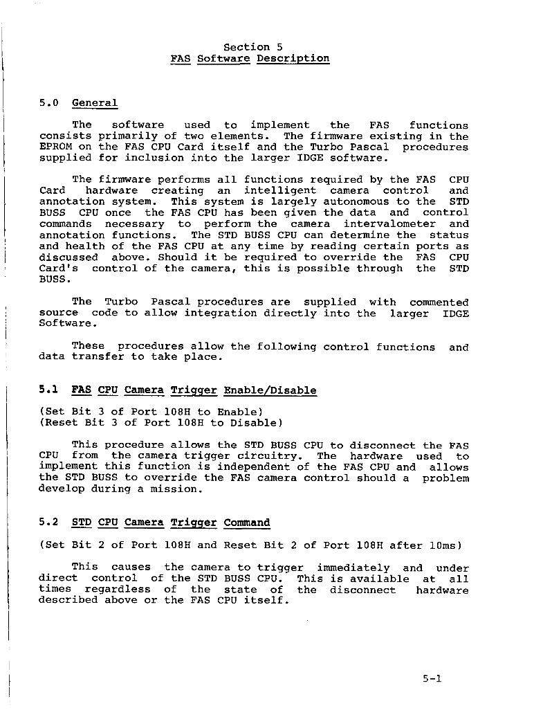
Section 5 - FAS Software Description
5.0 General
The software used to implement the FAS functions consists primarily of two elements. The firmware existing in the EPROM on the FAS CPU Card itself and the Turbo Pascal procedures supplied for inclusion into the larger IDGE software.
The firmware performs all functions required by the FAS CPU Card hardware creating an intelligent camera control and annotation system. This system is largely autonomous to the STD BUSS CPU once the FAS CPU ha5 been given the data and control commands necessary to perform the camera intervalometer and annotation functions. The STD BUSS CPU can determine the status and health of the FAS CPU at any time by reading certain ports as discussed above. Should it be required to override the FAS CPU Card's control of the camera, this is possible through the STD BUSS.
The Turbo Pascal procedures are supplied with commented source code to allow integration directly into the larger IDGE Software.
These procedures allow the following control functions and data transfer to take place.
5 . 1 -- FAS CPU Camera Trigger Enable/Disable
(Set Bit 3 of Port 108H to Enable) (Reset Bit 3 of Port 108H to Disable)
This procedure allows the STD BUSS CPU to disconnect the FAS CPU from the camera trigger circuitry. The hardware used to implement this function is independent of the FAS CPU and allows the STD BUSS to override the FAS camera control should a problem develop during a mission.
5 . 2
(Set Bit 2 of Port 108H and Reset Bit 2 of Port 108H after 10ms)
-- STD CPU Camera Trigger Command
This causes the camera to trigger immediately and under direct control of the STD BUSS CPU. This is available at all times regardless of the state of the disconnect hardware described above or the FAS CPU itself.
5-1
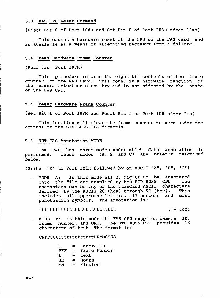
5.3 FAS CPU Reset Command
(Reset Bit 0 of Port 108H and Set Bit 0 of Port 108H after 10ms)
--
This causes a hardware reset of the CPU on the FAS card and is available as a means of attempting recovery from a failure.
5.4 Read Hardware Frame Counter
(Read from Port 107H)
This procedure returns the eight bit contents of the frame counter on the FAS Card. This count is a hardware function of the camera interface circuitry and is not affected by the state of the FAS CPU.
5.5 Reset Hardware Frame Counter
(Set Bit 1 of Port 108H and Reset Bit 1 of Port 108 after lms)
This function will clear the frame counter to zero under the control of the STD BUSS CPU directly.
5.6 SET FAS Annotation - MODE
The FAS has three modes under which data annotation is performed. These modes (A, B, and C) are briefly described below.
(Write "^M" to Port lOlH followed by an ASCII "A", "B" , @,cmt) - MODE A: In this mode all 28 digits to be annotated
onto the film are supplied by the STD BUSS CPU. The characters can be any of the standard ASCII characters defined by the ASCII 20 (hex) through 5F (hex), This includes all uppercase letters, all numbers and most punctuation symbols. The annotation is:
t = text tttttttttttttttttttttttttttt
- MODE B: In this mode the FAS CPU supplies camera ID, frame number, and GMT. The STD BUSS CPU provides 16 characters of text The format is:
CFFFttttttttttttttttHHMMSSSS
C = Camera ID FFF = Frame Number t = Text HH = Hours MM = Minutes
5-2
I
SSSS = Seconds of 0.01s - MODE C: In this mode the FAS CPU provides GMT and the
STD CPU will provide 19 text characters. The format is: tttttttttttttttttttDHHMMSSSS
t = Text D = Day (1's digit of day of month counter) HH = Hours MM = Minutes SSSS = Seconds to 0.01s
The text data is sent using a separate procedure described below. The procedure discussed here will only SET the mode.
5.7 Send Last Photo 'X' Switch Data to STD BUSS CPU
(Write "AN" to Port l O l H and Read 28 bytes from Port 100H)
-- -
Each time a photo is taken the "X" switch is used to freeze the data for use later to perform the annotation when the film is advanced. This data is held in memory until the next photo is taken. The STD BUSS CPU can request this data at any time up to -01 seconds prior to the next photo interval. During this -01
second window the FAS CPU will not honor a request for data from the last photo. Instead, the request is noted but not acted upon until after the impending photo is taken. Therefore, in this case, the data reported will reflect the photo just taken.
5.8 Receive Text from STD BUSS CPU
(Write "^O" to Port lOlH followed by 28 ASCII characters)
-----
This procedure allows a string of character data to be sent to the FAS CPU. The data is interpreted as text data to be printed according to the current mode as described in section 5.6 above. If more characters are sent than needed, the extra data is ignored.
5.9 Set GMT Time --- To set clock: Write ""P" followed by 5 bytes of binary data
in the following format: day (0-91, hours (0-231, minutes (0- 59), seconds (0-591, hundreds of seconds (0-99).
To start clock running: Write "^G" to Port 101H.
Using this procedure the STD BUSS CPU can set the RTC on the FAS Board. A string of data will define the current date and time to be loaded into the clock, but the clock will not be started until a separate "GO" command is sent. In this way more than one FAS Card can be set to the same time.
5-3
5.10 "GO" Command - to Start Clock
(Write ""G" to Port 101H)
A s discussed above, this procedure will start the RTC counting after time has been loaded.
5.11 - Set Intervalometer Parameters
Write ""Q" to Port lOlH followed by the number of photos (1 byte binary, 0-250). Next, send two bytes of binary (MSB first) photo interval, 0-14400.
This allows the STD BUSS CPU to give the FAS CPU information required to perform a photo sequence. This information includes the cruantity of pictures to be taken and the time interval between pictures. The quantity will range from 1 to 250 and the time interval from 0.25 to 3600 seconds in increments of 0.25 seconds.
The accuracy of this interval is +0.01 second and the time annotated onto the film is the time at-which the "X" switch was received.
5.12 - "GO" Command - to Start Photo Sequence
(Write ""R" to Port 101)
This procedure causes the photo sequence to begin by taking one picture immediately and the next photo one "time interval" later and continuing until the entire "quantity" of pictures is taken.
5.13 - FAS Camera Interface STATUS Code
Using this procedure the STD BUSS CPU is able to determine the status and health of the FAS CPU and camera interface circuitry by reading the FAS status bits from port 104H. This port is a dedicated port assigned to a unique STD BUSS 1/0 address and is available to the STD BUSS CPU at any time, independent of the FAS CPU. The FAS CPU will simply update the data in this port as the status of the hardware changes, Some of these status bits are only updated after a FAS self test command. This is summarized below: See Section 4.4.1.
- Camera Error Code: (updated as camera status changes) (Read from Port 104H)
a) Camera trigger sent but no "X" switch received. b) "X" switch received but no encoder pulses received. c) Encoder pulses received but terminated before a print
complete.
5-4
- FAS CPU Status Bits
a) Timeout reset has occurred:
This item is reported independent of the FAS CPU and software. This will indicate a probable failure of the FAS CPU and as such will only be indicating the hardware attempting to reset the CPU and all hardware with the exception of the hardware frame counter.
b) Self Test Result Bits:
- EPROM check sum verify/fail - RAM test pass/fail - CPU test pass/fail
(See Section 4.4.1 for error codes.)
These tests are performed upon power up and request, (by STD CPU), and results are reported back.
5.14 Cancel Current Photo Sequence
(Write 'Ins" to Port 101H)
Using this procedure the STD BUSS CPU can stop the current photo taking session at any time.
5.15 Interval Pre-Warning Flaq
(Read from Port 103H bit 0 only)
By reading this dedicated STD BUSS 1/0 port the STD BUSS CPU is able to detect (one second ahead of time) when a photo is about to be taken. See Sec t ion 4 . 4 . 2 .
5.16 Photo Confirmation to STD -- (Read from Port 102H bit 0 only)
By reading this dedicated STD BUSS 1/0 Port, the STD BUSS CPU can determine if an expected nhoto was actually taken. This port should be reset to a zero one quarter second prior to a photo, when a nhoto is triggered, or when the port is read by the STD CPU. This bit is set to a one if a photo is successfully taken. If the nhoto is unsuccessful, the STD BUSS CPU should read the camera status bits to determine the probable cause of the failure. See section 4.4.1.
5-5
5.17 Photo Count This Sequence
(Write "^X" to Port lOlH and read 1 byte binary from 100H)
The FAS is capable of reporting to the STD BUSS CPU how many nhotos of the current sequence have been taken. This count will increment every time the camera is triggered, up to the total quantity of photos required for the current sequence.
5.18 Perform FAS Communication -- Port Test - (Write "^Y" to Port 101H)
This procedure invoke the test routines on the FAS board to exercise all the communication hardware between the FAS and the STD BUSS CPU's.
5.19 Request FAS - Hardware Self Test (To perform for all tests, write "^T" to Port lOlH followed by an ASCII A)
Using this procedure the STD BUSS CPU can request the FAS to perform the following checks:
a) EPROM check/sum verify. (Write "^T" followed by an ASCII E to Port 101H)
b) RAM test with all ones, all zeros, and alternating ones and zeros. (Write "^T" followed by an ASCII R to Port 101H)
c) CPU self check routines. (Write followed by an ASCII C to Port 101H)
The results of these tests are made available to the STD BUSS CPU in the above mentioned STATUS port. (See sections 4.4.1 and 5.13.)
5.20 Report Annotation Mode to - STD (Write an "^L" to Port lOlH and Read one byte of ASCII from Port 100H)
The STD BUSS CPU can ask the FAS CPU which mode the annotator is currently in (A, B, or C). This software procedure performs a request using the data/ready ports (STD to FAS) and receives an answer using the data/ready ports (FAS to STD). The FAS card status port, a dedicated STD BUSS 1/0 Port, also contains this mode code.
5-6
5.21 Report Time Left to Next Scheduled Photo ---- (Write a 'rnV" to Port l O l H followed by two reads from Port 1 0 0 H ) (Read two bytes binary MSB first)
The STD BUSS CPU can access the intervalometer timer in the FAS CPU by requesting this item. The FAS will return the number of increments left until the next scheduled photo as a binary number 0 to 14,400. This would represent the time left in .25 second increments, (i.e. 3600 1/4 second intervals = 14,400).
5.22 - Set Software Frame Counter
(Write ''AHr' to Port l O l H followed by one byte binary frame count 0-250 1
This procedure allows the STD CPU to set the software frame counter to any value between 0 and 250.
5-7
1.0 INTRODUCTION
The following test procedure is meant to provide a means of
controller card (FAS) and camera. Each test outlined within this procedure is designed to test a specific portion of the FAS hardware as well as the command sequences associated with that hardware.
I verifying the functional operation of the film annotation
These test procedures are not meant to be a means of trouble shooting the FAS card but rather they are meant to provide documentation as to the functionality of each FAS card. After each FAS card has undergone preliminary testing and it is believed to work properly it will be subjected to the test procedures contained within this document to verify complete functionality.
A-3
2.0 TEST SET-UP
For all of the test procedures outlined in this document it is assumed that the person performing the tests has obtained the software, hardware and test equipment outlined in the next two sections. In addition, it is assumed the the individual executing the test has already installed the FAS card in the STD computer, has applied power, and has run the FASTEST-EXE test program provided by Miletus Associates,
2.1) Hardware & Software: The following is a list of the hardware necessary to perform the tests contained in this document:
1. 2. 3, 4. 5. 6 . 7. 8 . 9. 10 . 11 . 12,
Video monitor and keyboard Prolog computer card # 7890A-05 Prolog computer card # 735OC-01 Prolog computer card # 7717-01 Prolog computer card # 7391A-01 & 7390-02 Prolog computer card cage Prolog compatible power supply FAS controller card Modified 35mm camera Camera connection cable, # 8-1094 FASTEST-EXE test program Prolog extender card.
2.2) Test Equipment: The following is a list of test equipment necessary to perform the tests contained in this test specification:
1- Hewlett Packard logic analyzer model 1631D ( or equivalent machine capable of capturing and analyzing the microprocessor BUSS cycles of the National Semiconductor NSC-800 CPU running at eight Mhz )
2. Tektronix 100 Mhz oscilloscope model 2236 ( or equivalent )
3. Frequency Counter with a display accuracy of 10 PPM or better used to measure 1Hz clock counter ticks ( Tektronix Scope 2236 with option 001 1
A-4
3.0 TEST PROCEDURES
3.1 TEST FAS CPU RESET COMMAND ---- SETUP: Issue the "F" command and select mode "A". Issue the ''M" command, Note: the mode changes to "A" . Issue the "C" command. Followed by the 'IM" again.
RESULT: After the mode is changed to "A" , a reset command will restore the mode to ''B". The last "M" command will show Mode = B to pass this test.
3.2 TEST FAS STATUS CODE --- SETUP: Exit the FASSTD test program by pressing r l Z " . Turn off the power to the STD computer and wait at least ten seconds, Next, apply power to the STD computer and run the FASTEST test program. Finally, issue the "M" command,
RESULT: After issuing the "M" command, the mode status should equal "B", the card status should equal zero, and the camera status should equal zero, If this is not the result this test has failed.
3.3 PERFORM - FAS COMMUNICATION TEST - SETUP: Issue the "R" command from the FASTEST program.
RESULT: After waiting at least four seconds note the FAS error massage value located in the lower right-hand side of the computer screen. If the returned error code equals zero the communication port test has passed. Any other response constitutes a communication port failure.
3.4 PERFORM FAS HARDWARE TEST - - SETUP: Issue the ''S" command and select "A" as a response to the computer prompt.
RESULT: After waiting at least five seconds issue the "M" command to read the FAS status latch. If the FAS card error code result equals zero the hardware test has passed. Any other response constitutes a hardware failure.
3.5 - TEST - STD - CAMERA TRIGGER COMMAND SETUP: Connect FAS camera cable and camera to the FAS camera card, Apply power to the camera and Issue the "B" command.
RESULT: If the camera triggers once for each time the "B" command is sent, the test has passed.
A-5
3 . 6 TEST HARDWARE FRAME COUNTER
SETUP: First, send the "D" command to read the contents of the hardware frame counter. Next, issue the "B" command to trigger the camera, Lastly, issue the "D" command a second time and note the current count value. (Carefully repeat this test several times to insure proper operation.)
RESULT: Each time the camera is triggered the frame count should increase by one count and only one count. If after repeating this test twenty times the frame count increases by exactly
--
twenty, then this test has been passed.
3 . 7 TEST HARDWARE FRAME COUNTER RESET
SETUP: Issue the "E" command followed by the I'D" command, If returned value of the frame counter is zero then issue the command followed by the "D" command.
--
RESULT: If after performing this test the frame counter value one then this test has been passed.
3 . 8 TEST THE SEND DATA TO FAS COMMAND ------- SETUP: Type the "H" command and enter "ABCDEFGHIJKLMNOP" . RESULT: After waiting at least two seconds, note the result the FAS error code. If the error code is zero then this test passed.
the 'I B I'
is
of has
3 . 9 TEST THE SEND LAST 'IX" SWITCH DATA ------ SETUP: Send the "B" command followed by the "G" command.
RESULT: If the data received from the FAS is as follows, this test has passed, "CFFFABCDEFGHIJKLMNOPHHMMSSSS"
C = Camera ID, FFF = Frame count, HHMMSSSS = Time
NOTE! Camera ID, Frame count, and Time are undefined at this point in the test; therefore, it should not concern the operator that these fields are meaningless. However, what is important is that the text matches: "ABCDEFGHIJKLMNOP". (This data was entered in step 3 . 8 )
3.10 TEST THE ANNOTATION MODE COMMAND --- SETUP: Issue the "F" command and enter "A" in response to the computer prompt. Enter the "H" command and type in a unique combination of data. Next, enter the "B" command to trigger followed by the "G" command. Check the data that is returned from
A-6
1 the FAS and insure that it is identical to the data that was just sent. Repeat this test with the exception of entering a "C" in
1 response to the computer prompt and realizing that the data returned will be comprised of the text sent followed by day and time data which at this point are undefined.
1
I
RESULT: If the data returned from the FAS is identical to the data sent to the FAS this test has passed.
3.11 TEST FAS REAL TIME CLOCK ----- SETUP: Issue the "F" command and enter mode "C". Send the "I" command and enter "123450000'' and press return. Next, issue the
command to start the clock. Finally, type the "Blr command followed by the "G" command. #I J V I
RESULT: Verify that the time returned is equal to the time sent plus the time between the issuing of "J" command and the sending of the "B" command. If it is found that the time is correct within reasonable tolerances then this test has passed.
I 3.12 TEST FAS INTERVALOMETER
SETUP: First, setup the analyzer in the timer mode to start and stop on a fetch from address OB77 hex. Second, Send the "K" command and enter a request to take thirty pictures on an interval of one (.25 seconds). Third, issue the "L" command to start the nhoto sequence and verify that the camera is being
--- I
1
i triggered.
RESULT: Verify that the analyzer's measured time is 250 ms which will constitute a passing of this test. 1 Note: If an analyzer is not available, a stop watch can be used I
1 I to give an approximate time. This test should actually be done by the manufacturer and fine tuned to factory (manufacturer) specifications. The stop watch will give a ball park time which is all that is necessary since adjustments cannot be made at the user level.
-
I
3.13 TEST THE CANCEL PHOTO SEQUENCE COMMAND
SETUP: Issue the "L" command and before the camera has completed it's thirty photographs enter the "N" command.
RESULT: Observe whether the camera stops triggering promptly after the "N" command is issued. If this behavior is observed then this test has passed.
---
A-7
3.14 TEST THE INTERVAL PRE-WARNING FLAG --- SETUP: Issue the "K" command and enter 250 photos at 16 intervals (every 4 seconds). Issue the "L" followed by the "Y" command.
RESULT: When the time remaining until the next scheduled photo counts down below 5, the interval pre-warning flag will change to say "Photo Pending." When the count goes to zero, which is usually not seen on the screen, the camera will click and the test program reports a "Successful Photo Taken" message. If this
stop this test. occurs, then the test has been passed. Issue the "N" and "Y" to
3.15 TEST THE PHOTO CONFORMATION BIT --- NOTE: It is recommended that the following test be performed by the manufacturer ONLY.
SETUP: Turn off the power. Disconnect jumper (W3) or take out pin 25 of the camera Berg connector located at 53 on the FAS card and after power up, issue the "Bo' command. Next, observe the state of the photo confirmation, command "P'l . If the photo confirmation status is "No Photo Taken" then turn off power and reconnect the encoder pulses. Then turn on power and issue the ''B'' command a second time. This time a successful Dhoto confirmation status should be observed.
RESULT: If the operator observes the above conditions this test has passed. (Note: reconnect jumper (W3)
3.16 TEST THE PHOTO SEQUENCE COUNT --- SETUP: Start the camera by taking a photo sequence and then issue the "Q" command repeatedly.
RESULT: The operator should observe the sequence photo counter "Q" to be incrementing. If this observation is made this test has passed. Use command "N" to stop the photo sequence.
3.17 TEST THE REPORT ANNOTATION MODE COMMAND --- SETUP: First issue the "F" command and respond "A" to the computer prompt. Next, issue the "T" command followed by the "M" command. Repeat for modes "B" and "C".
RESULT: If the annotation mode that is reported in response to the "T" and "M" commands is "A", "B", "C" then this test has passed.
A-0
3.18 TEST THE REPORT --- TIME TO NEXT PHOTO COMMAND
SETUP: Start the camera taking photos on two second intervals. Next, issue the "U" command repeatedly and verify that the time to next -hot0 count is decreasing.
---
RESULT: If it is found that the time to next photo count is decreasing then this test has been passed. Use command "N" to stop the nhoto sequence.
3.19 TEST PHOTO EXPOSURE TIMES -- NOTE: It is recommended that the following test be performed by the manufacturer ONLY.
SETUP: Attach channel one of the oscilloscope to pin 60 or Test Point One (TP1) of the PNT EPLD (U3). The exposure time "E" 16us, has already been pre set by the jumper between pins 5 and 12 of U4. Start a photo sequence. Make sure that the positive going pulse width is approximately 16us.
RESULT: A 16us + 1 - 2us positive pulse width should be observed.
3.20 TEST REAL TIME CLOCK CALIBRATION ---- NOTE: the manufacturer ONLY.
It is recommended that the following test be performed by
SETUP: Issue the "VI' command to set the FAS real time clock into the 1Hz interrupt mode. After issuing this command the FAS will remain in the 1Hz interrupt mode for three minutes or until any other key is pressed. Next, connect the frequency counter to pin 22 of u9.
RESULT: Verify that the frequency measurement is 1HZ +/- 10 PPM. However, the operator should not be concerned if the frequency count jumps +/- 30 PPM due to the sampling time of the frequency counter . 3.21 PERFORM FILM TEST
NOTE: It is recommended that the following test be performed by the manufacturer ONLY.
--
SETUP: Load the camera with approximately thirty frames of film and take photos with fixed data in all of the print modes.
RESULT: Insure that the annotated data appears correctly on the film without any scratches caused by the annotation head. Also insure that the camera is advancing film correctly.
A-9
( * Miletus Associates, Inc. STD to FAS Unit Procedures * ) { SR- 1 {Range checking off) {SB+l (Boolean complete evaluation on) {SS+) {Stack checking on) {SI+) {I/O checking on) (SN-1 {No numeric coprocessor) {SM 65500,16384,655360) {Turbo 3 default stack and heap)
. . . . . . . . . . . . . . . . . . . . . . . . . . . . . . . . . . . . . . . . . . . . . . . . . . . . . . . . . . .
. . . . . . . . . . . . . . . . . . . . . . . . . . . . . . . . . . . . . . . . . . . . . . . . . . . . . . . . . . . ( * * * *** ) (*** FAS AND STD UNIT PROCEDURES * * * ) (*** REVISION 2.0 * * * ) ( *** *** ) ( * * * ( *** ( *** ( *** ( *** ( *** ( * * * 9 DEC ( *** (*** ( ***
BY: TOM CAVALLI * * * ) JUNE 1988 *** )
LAST MODIFIED:13 MARCH 1989 *** ) FILENAME: FASSTD20.TPS ***) COMPILES: FASSTD20.TPU *** )
* * * ) 88: Load the FAS software frame count(VAR ***I
FAS ERROR CODE, NEW - FEAME - C~UNT :BYTE); ***I wasadded: *** )
*** ) (***14 DEC 88: Modified FAS Hardware Self Test to state***) (*** when the test has succesfully finished. * * * ) ( * * * ***) (***16 DEC 88: Converted the FASSTD procedures into a ***) ( *** unit. The private GLOBAL variable, *** ) ( * * * FAS TRIGGER ENABLE SAVE, allows those ***I ( *** procedures which set the FAS control *** ) ( *** bits to function with out passing the *** ) ( *** current trigger enabled/disabled value * * * ) ( *** * * * ) . . . . . . . . . . . . . . . . . . . . . . . . . . . . . . . . . . . . . . . . . . . . . . . . . . . . . . . . . . . . . . . . . . . . . . . . . . . . . . . . . . . . . . . . . . . . . . . . . . . . . . . . . . . . . . . . . . . . . .
B-3
( * Miletus Associates, Inc. STD to FAS Unit Procedures * )
( * The following TURBO PASCAL (V5) procedures support the operation of the Miletus Film Annotation System (FAS) camera card.
There are twenty two procedure calls and various utility procedures that will activate the FAS card. Each procedure call contains the parameters necessary for correct operation. These parameters provide the communication path between the STD and FAS. A list of the these parameters can be found the FASTEST.TP4 source code. For instance, an error code parameter is passed between each procedure and reports the error status. This error code should be checked by the user's program to verify successful completion of the called procedure. In PASCAL, IF A FAS Error Has Occured(FAS - ERROR - CODE) is TRUE then the called procedure has failed.
The user can NOT call any of the utility procedures
A FAS Error Occured Get E&-or-Code-Number Get-Error Code - Caller FAS-Power-Up
which follow EXCEPT:
Upon power up The user must first call the Fas Power - Up procedure which will initialize the FAS: the FZS Annotation mode equals 'B', and the FAS camera trigger is enabled.
the uses clause contains FASSTD2O so that a screen menu program can test the FAS. Although the FASTEST.TP5 program only displays the error code after each procedure call, the user must perform an error code check. * I
The FASTEST.TP5 test program serves as an example where
B-4
( * Miletus Associates, Inc. STD to FAS Unit Procedures * )
UNIT FASSTD20; INTERFACE uses crt; ( * for the DELAY0 procedure * )
. . . . . . . . . . . . . . . . . . . . . TYPE DECLARATIONS . . . . . . . . . . . . . . . . . . . .
TYPE STRING 4 = STRING[4]; (*FOR THE COMMUNICATION TEST*) STRING110 = STRING[lO]; ( * FOR CONTROL CODE + GMT * ) STRING 9 = STRING[9]; ( * FOR GMT 'DHHMMSSSS' * ) STRING-28 = STRING[28]; ( * FOR TEXT ANNOTATION * ) STRING-29 - = STRING[29]; ( * FOR CONTROL CODE + TEXT * )
B-5
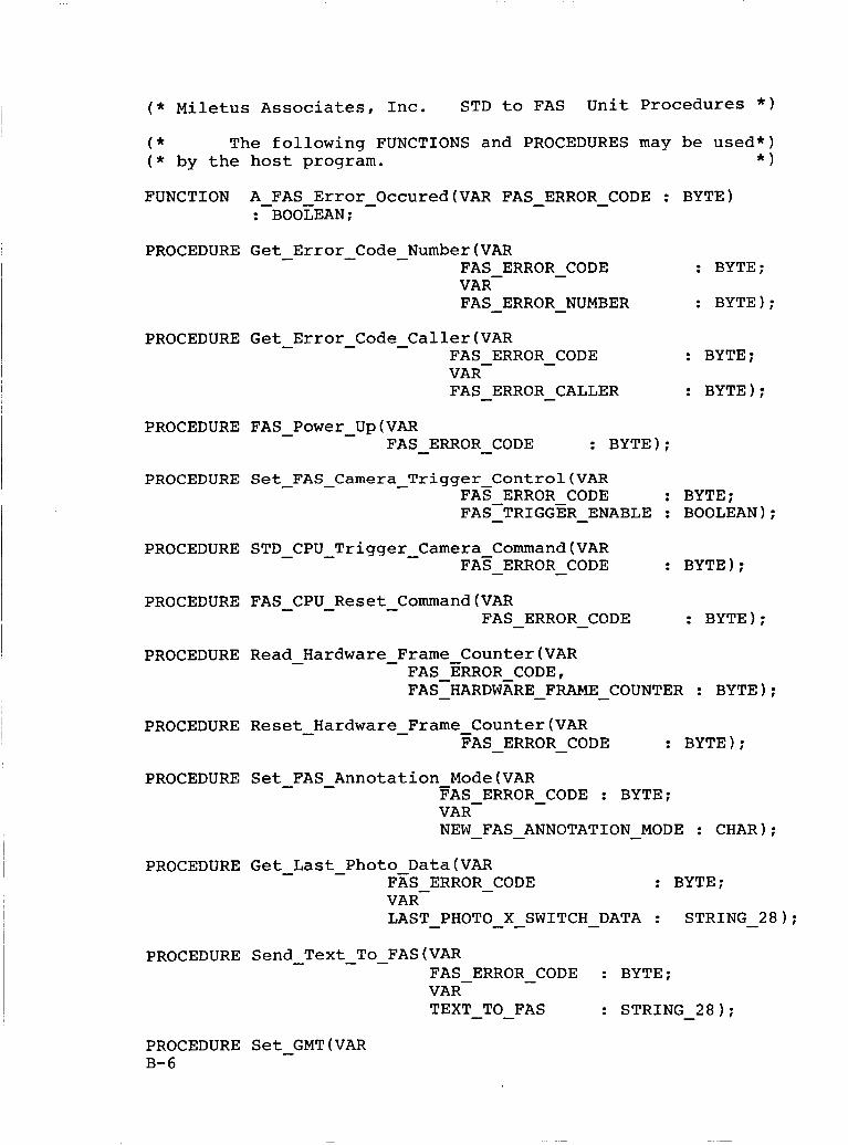
( * Miletus Associates, Inc. STD to FAS Unit Procedures * )
( * The following FUNCTIONS and PROCEDURES may be used*) ( * by the host program. * )
FUNCTION A - FAS Error - Occured(VAR FAS - ERROR - CODE : BYTE) : BOOEEAN;
PROCEDURE Get - Error - Code - Number(VAR FAS ERROR CODE : BYTE;
FAS - ERROR - NUMBER : BYTE);
- VAR-
PROCEDURE Get - Error - Code - Caller(VAR FAS ERROR - CODE : BYTE;
FAS - ERROR - CALLER : BYTE); VAR-
PROCEDURE FAS - Power - Up(VAR FAS - ERROR - CODE : BYTE);
PROCEDURE Set-FAS-Camera - Trigger Control(VAR FAS ERROR CODE : BYTE; FAS-TRIGGER - - ENABLE : BOOLEAN);
PROCEDURE STD - CPU - Trigger - Camera Command(VAR : BYTE); FA^ - ERROR - CODE
PROCEDURE FAS - CPU-Reset - Command(VAR FAS - ERROR - CODE : BYTE);
PROCEDURE Read - Hardware - Frame Counter(VAR FAS ERROR CODE, FAS-HARDWARE - - FRAME - COUNTER : BYTE);
PROCEDURE Reset-Hardware - Frame - Counter(VAR FAS - ERROR - CODE : BYTE);
PROCEDURE Set - FAS - Annotation - Mode(VAR FAS ERROR - CODE : BYTE;
NEW - FAS - ANNOTATION - MODE : CHAR); VAR-
PROCEDURE Get - Last - Photo Data(VAR FAS ERROR - CODE : BYTE;
LAST - PHOTO - - X SWITCH - DATA : VAR-
STRING - 2 8 ) ;
PROCEDURE Send - Text - To-FAS(VAR FAS ERROR - CODE : BYTE;
TEXT - - TO FAS : STRING - 2 8 ) ; VAR-
PROCEDURE Set - GMT(VAR B-6
( * Miletus Associates, Inc. STD to FAS Unit Procedures * )
FAS ERROR - CODE : BYTE;
NEW - GMT : STRING - 9); VAR-
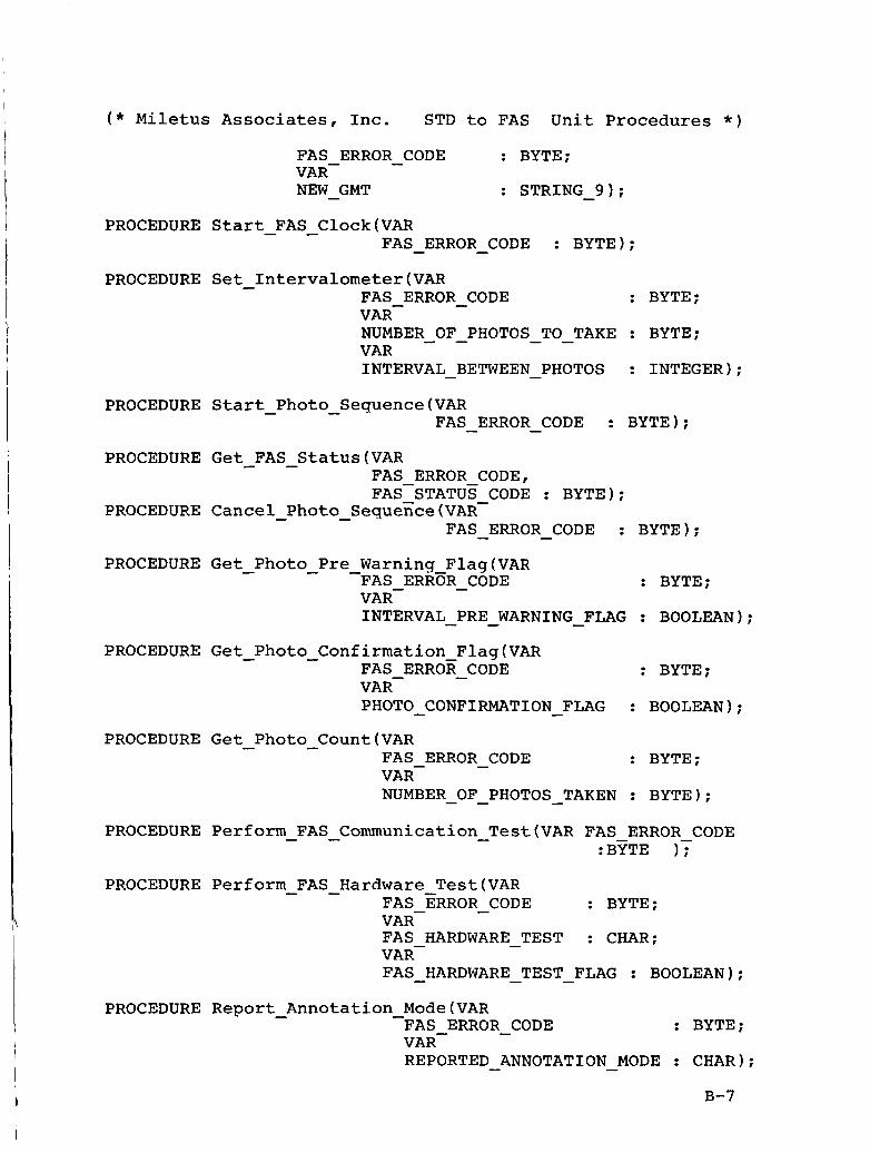
PROCEDURE Start - FAS - Clock(VAR FAS - ERROR - CODE : BYTE);
PROCEDURE Set Intervalometer(VAR FAS ERROR - CODE VAR-
: BYTE;
NUMBER OF PHOTOS TO TAKE : BYTE; VAR INTERVAL BETWEEN PHOTOS : INTEGER);
- - - -
- -
PROCEDURE Start - Photo-Sequence(VAR FAS - ERROR - CODE : BYTE);
PROCEDURE Get FAS - Status(VAR
PROCEDURE Cancel - Photo - Sequence(VAR-
FAS ERROR CODE, FAS-STATUS CODE : BYTE);
FAS ERROR CODE : BYTE); - - PROCEDURE Get - Photo - Pre - Warning Flag(VAR
FAS ERRBR - CODE : BYTE;
INTERVAL PRE WARNING FLAG : BOOLEAN); VAR-
- - - PROCEDURE Get Photo - Confirmation Flag(VAR
FAS ERROR - CODE : BYTE;
PHOTO - CONFIRMATION FLAG : BOOLEAN); VAR-
PROCEDURE Get Photo Count(VAR - FAS ERROR - CODE : BYTE;
NUMBER OF PHOTOS TAKEN : BYTE); VAR-
- - - PROCEDURE Perform - FAS - Communication - TestfVAR FAS ERROR CODE
:BYTE 17 PROCEDURE Perform FAS - Hardware Test(VAR -
FAS ERROR - CODE : BYTE;
FAS HARDWARE TEST : CHAR;
FAS HARDWARE TEST - FLAG : BOOLEAN);
VAR-
VAR- -
- - PROCEDURE Report - Annotation - Mode(VAR
FAS ERROR - CODE : BYTE;
REPORTED ANNOTATION MODE : CHAR); VAR-
- -
I B-7
( * Miletus Associates, Inc. STD to FAS Unit Procedures * )
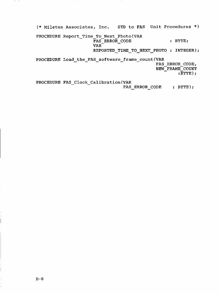
PROCEDURE Report - Time - To Next Photo(VAR FAS-ERROR - CODE : BYTE;
REPORTED TIME TO NEXT PHOTO : INTEGER); VAR-
- - - - PROCEDURE Load - the - FAS - software-frame - count(VAR
FAS ERROR CODE,
:BYTE ) ; NEP-FRAME-COUNT - -
PROCEDURE FAS - Clock - Calibration(VAR FAS - ERROR - CODE : BYTE);
B-8
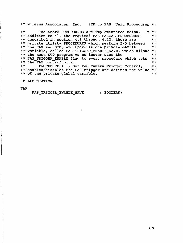
( * Miletus Associates, Inc. STD to FAS Unit Procedures
( * The above PROCEDURES are implementated below. In ( * addition to all the required FAS PASCAL PROCEDURES ( * described in section 4.1 through 4.22, there are ( * private utility PROCEDURES which perform 1/0 between ( * the FAS and STD, and there is one private GLOBAL ( * variable, called FAS TRIGGER ENABLE SAVE, which allows ( * the host STD program-to no longer pass the ( * FAS TRIGGER ENABLE flag to every procedure which sets ( * the-FAS control bits. ( * PROCEDURE 4.1, Set FAS Camera Trigger Control, ( * enables/disables the FAE trigger a6d defines the value ( * of the private global variable.
IMPLEMENTATION
VAR FAS - TRIGGER - ENABLE - SAVE : BOOLEAN;
* )
B-9
( * Miletus Associates, Inc. STD to FAS Unit Procedures * )
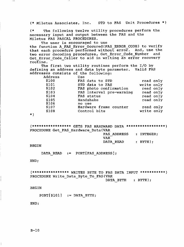
( * The following twelve utility procedures perform the necessary input and output between the FAS and the Miletus FAS PASCAL PROCEDURES.
the function A FAS Error Occured(FAS ERROR CODE) to verify that each proczdure performed without error. And, use the two error decoding procedures, Get Error Code Number and Get Error-Code-Caller to aid in writing an error recovery rou'iine.
defining an address and data byte parameter. Valid FAS addresses consists of the following:
The user is encouraged to use
The first two utility routines perform the 1/0 by
Address Use $100 FAS data to STD read only $101 STD data to FAS write only $102 FAS photo confirmation read only $103 FAS interval pre-warning read only $104 FAS status read only $105 Handshake read only $106 no use $107 Hardware frame counter read on ly $108 Control bits write only
* I
DATA - READ := PORT[FAS - ADDRESS];
END ;
(**************** WRITES BYTE TO FAS DATA INPUT ***********) PROCEDURE Write - Data - Byte - To-FAS(VAR
DATA - BYTE : BYTE);
BEGIN
PORT[$101] := DATA - BYTE;
END :
B-10
( * Miletus Associates, Inc. STD to FAS Unit Procedures * )
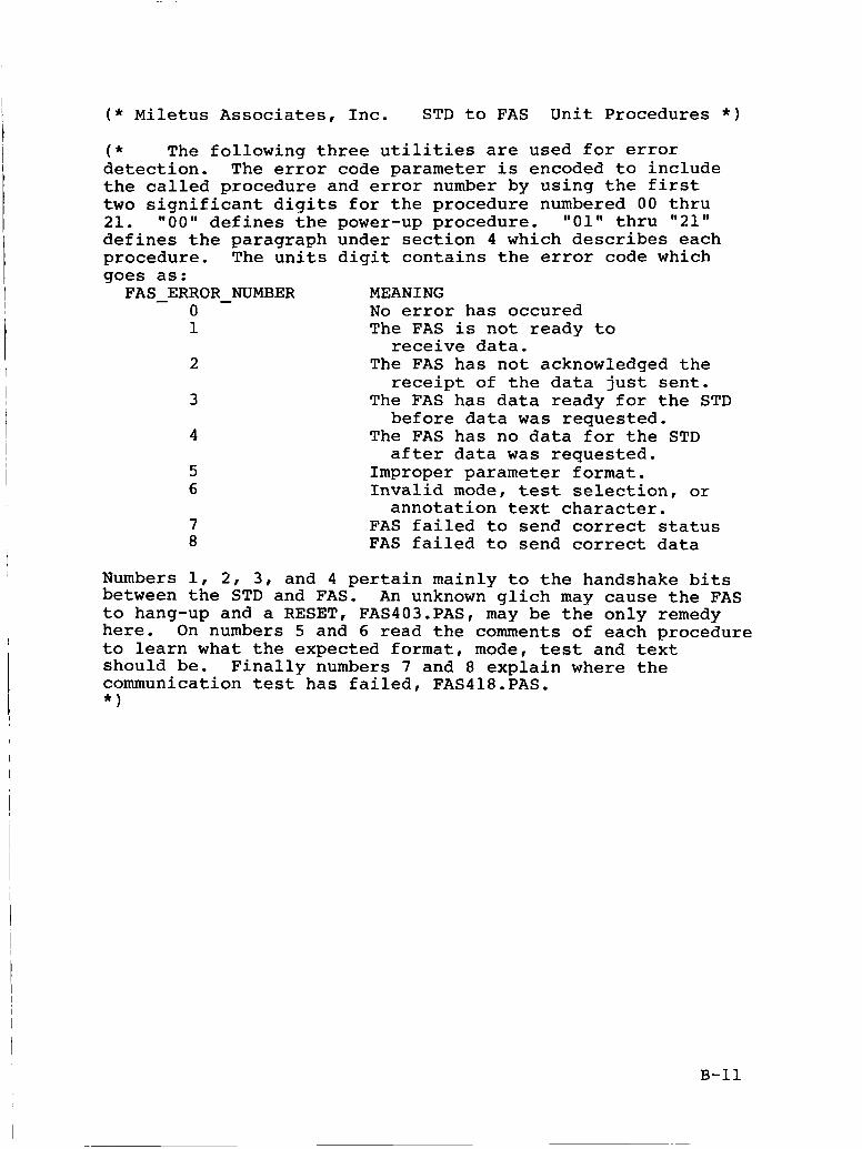
( * The following three utilities are used for error detection. The error code parameter is encoded to include the called procedure and error number by using the first two significant digits for the procedure numbered 00 thru 21. 1100" defines the power-up procedure. "01" thru "21" defines the paragraph under section 4 which describes each procedure. The units digit contains the error code which goes as:
MEANING 0 No error has occured 1 The FAS is not ready to
receive data. 2 The FAS has not acknowledged the
receipt of the data just sent. 3 The FAS has data ready for the STD
before data was requested. 4 The FAS has no data for the STD
after data was requested. 5 Improper parameter format. 6 Invalid mode, test selection, or
7 FAS failed to send correct status 8 FAS failed to send correct data
FAS c ERROR - NUMBER
annotation text character.
Numbers 1, 2, 3, and 4 pertain mainly to the handshake bits between the STD and FAS. to hang-up and a RESET, FAS403.PAS, may be the only remedy here. On numbers 5 and 6 read the comments of each procedure to learn what the expected format, mode, test and text should be. Finally numbers 7 and 8 explain where the communication test has failed, FAS418.PAS. * )
An unknown glich may cause the FAS
B-11
( * Miletus Associates, Inc. STD to FAS Unit Procedures * )
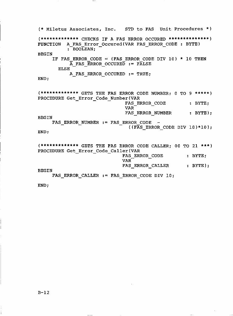
(************* CHECKS IF A FAS ERROR OCCURED **************I FUNCTION A - FAS Error - Occured(VAR FAS - ERROR - CODE : BYTE)
BEGIN : BOOLEAN;
A - FAS - ERROR - OCCURED := FALSE IF FAS - ERROR CODE = (FAS ERROR CODE DIV 10) * 10 THEN ELSE
A - FAS - ERROR - OCCURED := TRUE; END ;
(************* GETS THE FAS ERROR CODE NUMBER; 0 TO 9 *****I PROCEDURE Get Error Code Number(VAR - - -
FAS ERROR - CODE VAR-
: BYTE;
FAS - ERROR - NUMBER : BYTE);
((FZS ERROR CODE DIV 10)*10);
BEGIN FAS ERROR NUMBER := FAS ERROR CODE - - - -
- - END :
(************* GETS THE FAS ERROR CODE CALLER; 00 TO 21 *** ) PROCEDURE Get-Error-Code-Caller(VAR
FAS ERROR - CODE : BYTE;
FAS - ERROR - CALLER : BYTE); VAR-
BEGIN FAS - ERROR - CALLER := FAS - ERROR - CODE DIV 10;
END ;
B-12
( * Miletus Associates, Inc. STD to FAS Unit Procedures * )
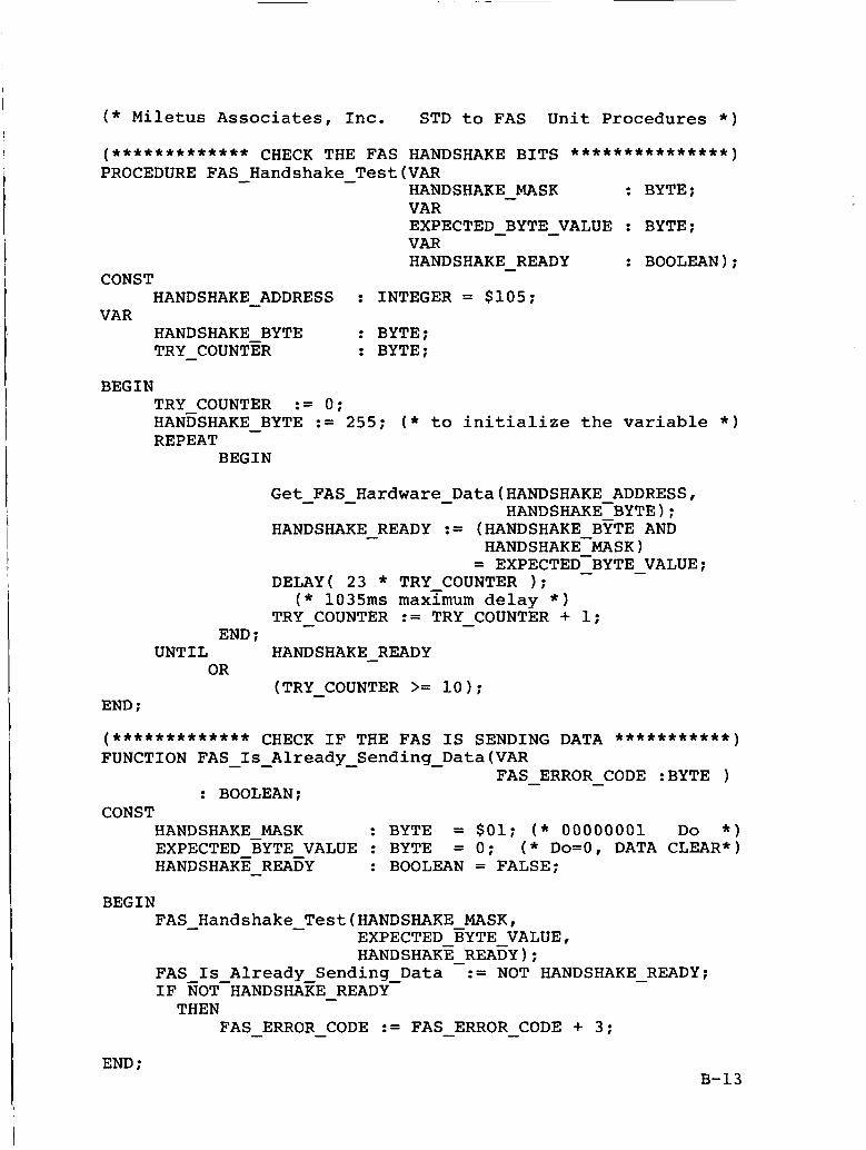
(************* CHECK THE FAS HANDSHAKE BITS ***************) PROCEDURE FAS - Handshake - Test(VAR
HANDSHAKE MASK ; BYTE: VAR EXPECTED BYTE - VALUE : BYTE: VAR HANDSHAKE - READY : BOOLEAN):
-
-
CONST
VAR HANDSHAKE - ADDRESS : INTEGER = $105;
HANDSHAKE BYTE : BYTE; TRY - COUNTER : BYTE;
BEGIN TRY COUNTER := 0; HANESHAKE - BYTE := 255; ( * to initialize the variable * ) REPEAT
BEGIN
Get - FAS - Hardware - Data(HANDSHAKE ADDRESS, HANDSHAKE-BYTE);
HANDSHAKE - READY := (HANDSHAKE BYTE AND HANDSHAKE-MASK
= EXPECTED-BYTE - - VALUE: DELAY( 23 * TRY COUNTER 1:
( * 1035ms maxymum delay * ) TRY - COUNTER := TRY - COUNTER + 1;
END ; HANDSHAKE READY
(TRY-COUNTER >= 10); - UNTIL
OR
END :
(************* CHECK IF THE FAS IS SENDING DATA ***********) FUNCTION FAS - - Is Already - Sending - Data(VAR
FAS - ERROR - CODE :BYTE ) : BOOLEAN:
CONST HANDSHAKE MASK ; BYTE = $01; ( * 00000001 Do * )
HANDSHAKE - READY : BOOLEAN = FALSE: EXPECTED BYTE VALUE : BYTE = 0; ( * DO=O, DATA CLEAR*)
BEGIN FAS - Handshake - Test(HANDSHAKE MASK,
FAS Is Already Sending Data := NOT HANDSHAKE - READY;
EXPECTED EYTE VALUE, HANDSHAKE - REAEY) ;
IF GOT-HANDSHAKE - READY- THEN
FAS - ERROR - CODE := FAS - ERROR - CODE + 3 ;
END : B-13
( * Miletus Associates, Inc. STD to FAS Unit Procedures * )
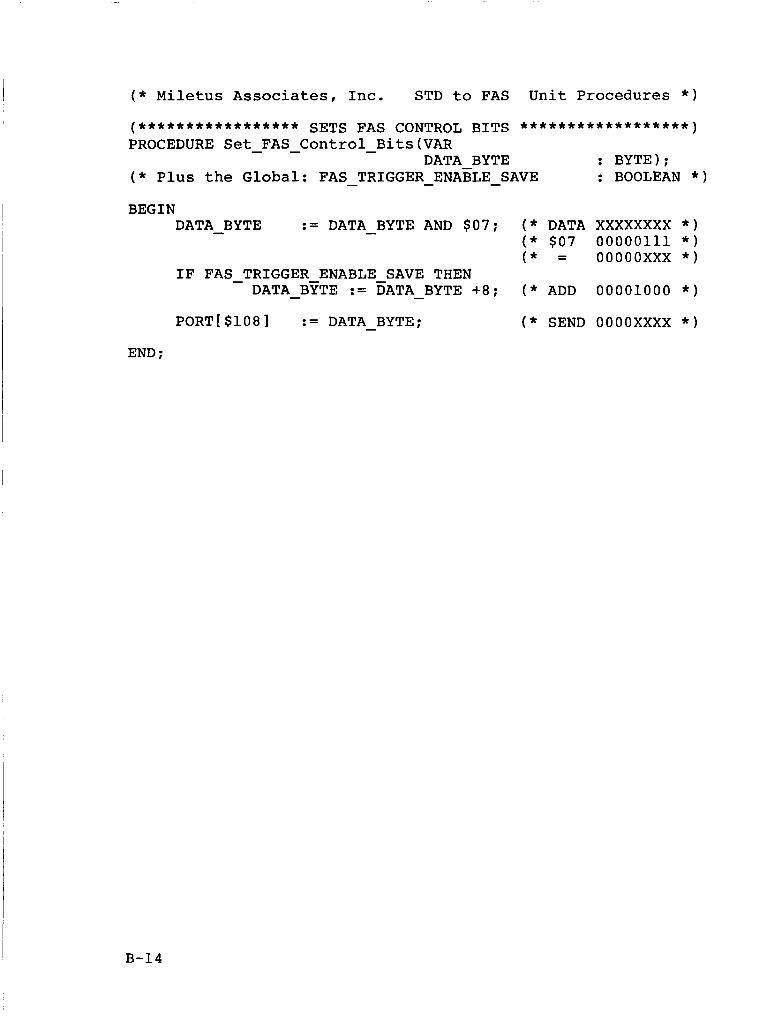
BEGIN := DATA BYTE AND $07; ( * DATA XXXXXXXX * )
( * $07 00000111 * ) - DATA BYTE
( * = oooooxxx * ) IF FAS TRIGGER ENABLE SAVE THEN - -
DATA - BYTE := DATA - BYTE +8; ( * ADD 00001000 * )
PORT[$108] := DATA - BYTE; ( * SEND OOOOXXXX * )
END ;
B-14
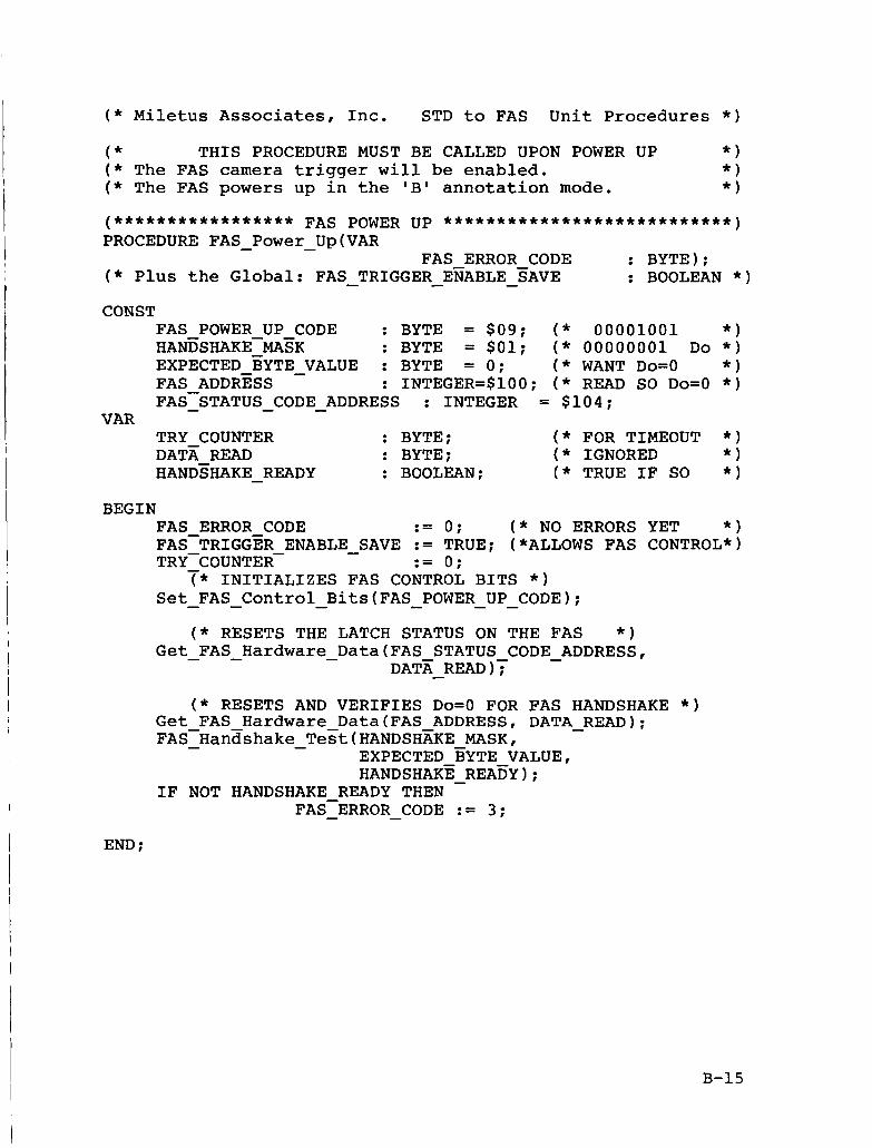
( * Miletus Associates, Inc. STD to FAS Unit Procedures * )
( * THIS PROCEDURE MUST BE CALLED UPON POWER UP * ) ( * The FAS camera trigger will be enabled. * ) ( * The FAS powers up in the 'B' annotation mode. * I
CONST FAS POWER UP CODE : BYTE = $09; ( * 00001001 * ) HANDSHAKE-MASK : BYTE = $01; ( * 00000001 Do * )
FAS ADDRESS : INTEGER=$100; ( * READ SO Do=O * ) EXPECTED EYTE - VALUE : BYTE = 0; ( * WANT Do=O * I
FAS-STATUS - - CODE - ADDRESS : INTEGER = $104; VAR
TRY COUNTER : BYTE; ( * FOR TIMEOUT * )
HANDSHAKE - READY : BOOLEAN; ( * TRUE IF SO * ) DATA READ : BYTE; ( * IGNORED * )
BEGIN FAS ERROR CODE := 0; ( * NO ERRORS YET * ) FACTRIGGER ENABLE - SAVE := TRUE; (*ALLOWS FAS CONTROL*)
( * INITIALIZES FAS CONTROL BITS * ) Set - FAS - Control - Bits(FAS - POWER - - UP CODE);
TRY-COUNTER- - := 0;
( * RESETS THE LATCH STATUS ON THE FAS * ) Get - FAS - Hardware - Data(FAS STATUS CODE - ADDRESS,
DATA - READ ( * RESETS AND VERIFIES Do=O FOR FAS HANDSHAKE * )
Get FAS Hardware Data(FAS ADDRESS, DATA READ); FAS-Hanashake - - Tegt(HANDSHfiKE MASK,
- EXPECTED BYTE VALUE, HANDSHAKE - READY);
FAS-ERROR - - CODE := 3 ; IF NOT HANDSHAKE READY THEN
END ;
B-15
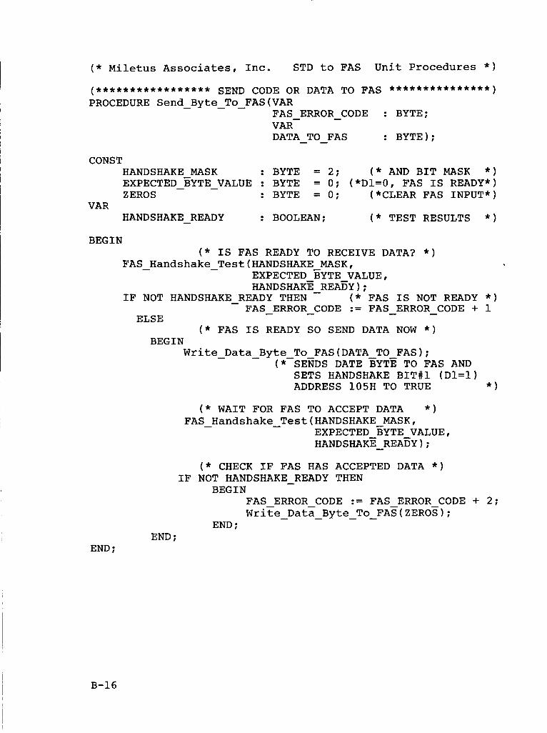
( * Lletus Associates, Inc. STD to FAS Unit Procedures * )
CONST HANDSHAKE MASK : BYTE = 2; ( * AND BIT MASK * )
ZEROS : BYTE = 0; (*CLEAR FAS INPUT*)
HANDSHAKE - READY : BOOLEAN; ( * TEST RESULTS * )
EXPECTED - BYTE - VALUE : BYTE = 0; (*D~=o, FAS IS READY*)
VAR
BEGIN ( * IS FAS READY TO RECEIVE DATA? * )
FAS - Handshake - Test(HANDSHAKE MASK, EXPECTED EYTE VALUE, HANDSHAKE - REABY);
IF NOT HANDSHAKE READY THEN ( * FAS IS NOT READY * ) - FAS ERROR - CODE := FAS - ERROR - CODE + 1 - ELSE
( * FAS IS READY SO SEND DATA NOW * ) BEGIN
Write - Data - Byte To FAS(DATA TO FAS); (*-SENDS DATE BYTE TO FAS AND
SETS HANDSHAKE BIT#1 (D1=1) ADDRESS 105H TO TRUE * )
END ;
( * WAIT FOR FAS TO ACCEPT DATA * ) FAS - Handshake - Test(HANDSHAKE MASK,
EXPECTED BYTE VALUE, HANDSHAKE - READY);
( * CHECK IF FAS HAS ACCEPTED DATA * ) IF NOT HANDSHAKE - READY THEN
BEGIN FAS ERROR CODE := FAS ERROR CODE + 2; Write Data Byte To FAS(ZER0S) ; - - - -
END ; END ;
B-16
I
1
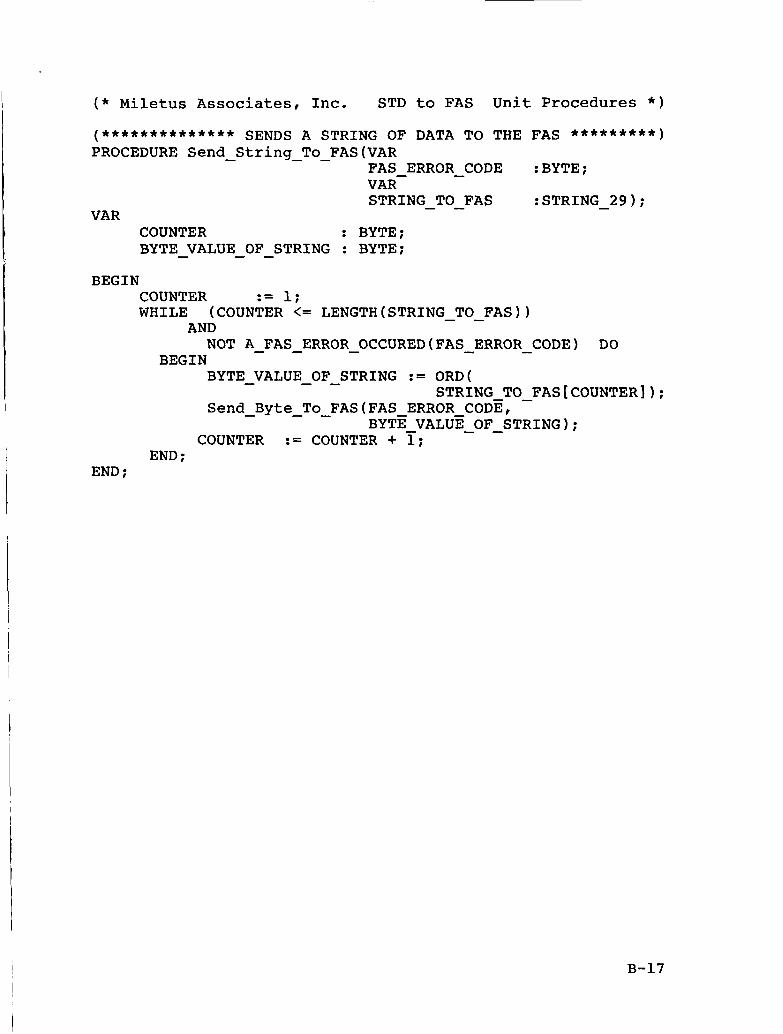
( * Miletus Associates, Inc. STD to FAS Unit Procedures * )
(************** SENDS A STRING OF DATA TO THE FAS *********I PROCEDURE Send - String - - To FAS(VAR
FAS ERROR - CODE :BYTE;
STRING - TO-FAS VAR-
:STRING - 29); VAR
COUNTER : BYTE: BYTE VALUE OF STRING : BYTE; - - -
BEGIN COUNTER := I: WHILE (COUNTER <= LENGTH(STR1NG - - TO FAS))
AND NOT A - FAS - ERROR - OCCURED(FAS - ERROR - CODE) DO
BEGIN BYTE VALUE OF STRING := ORD(
Send - Byte - - To FAS(FAS ERROR CODE,
- - - STRING TO - FAS[COUNTER]);
BYTE VALUE - - OF STRING); COUNTER := COUNTER + i;
END : END ;
B-17
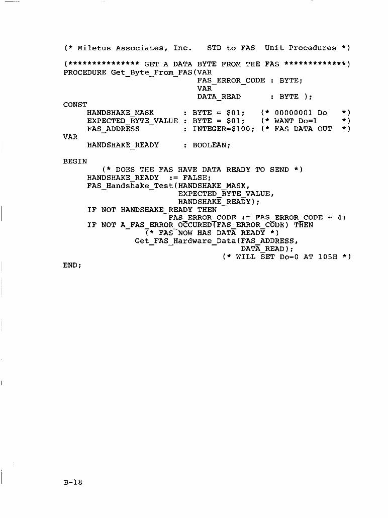
( * Miletus Associates, Inc. STD to FAS Unit Procedures * )
(*************** GET A DATA BYTE FROM THE FAS e* * * * * * * * * * * * ) PROCEDURE Get - Byte - From - FAS(VAR
FAS ERROR - CODE : BYTE; DATA - READ : BYTE 1; VAR-
CONST HANDSHAKE MASK : BYTE = $01; ( * 00000001 Do * )
* ) FAS - ADDRESS : INTEGER=$100; ( * FAS DATA OUT * )
HANDSHAKE - READY : BOOLEAN;
EXPECTED BYTE - VALUE : BYTE = $01; ( * WANT DO=^
VAR
BEGIN ( * DOES THE FAS HAVE DATA READY TO SEND * )
HANDSHAKE READY := FALSE; FAS - HandsKake - Test(HANDSHAKE MASK,
EXPECTED BYTE VALUE, HANDSHAKE - REA~Y);
IF NOT HANDSHAKE - READY THEN FAS ERROR CODE := FAS ERROR CODE + 4;
IF NOT A - FAS ERROR OCCUREDTFAS ERROR CGDE) TEEN T* FAS-NOW HAS DATA READY * )
Get - FAS - Hardware - Data(FAS ADDRESS, DATK READ) ;
( * WILL SET Do=O AT 105H * ) END ;
B-18
i
, I
I
I I i
I
I:
I
( * Miletus Associates, Inc. STD to FAS Unit Procedures * )
(****** 4.1 FAS CPU CAMERA TRIGGER ENABLE/DISABLE * * * * * * * I
PROCEDURE Set 4 FAS - Camera - Trigger Control(VAR
( * Plus the Global: FAS - TRIGGER - EiABLE - SAVE FAS ERROR CODE : BYTE; FAS-TRIGGER ENABLE : BOOLEAN);
: BOOLEAN * )
CONST NORMAL - CONTROL - BYTE : BYTE = $09; ( * 00001001 * )
BEGIN
FAS - ERROR - CODE := 010;
FAS - TRIGGER - ENABLE - SAVE := FAS - TRIGGER - ENABLE; Set FAS Control Bits(N0RMAL CONTROL BYTE); - - - - -
END ;
B-19
( * Miletus Associates, Inc. STD to FAS Unit Procedures * )
( * Calling this procedure will cause the FAS to * ) ( * override software and trigger the camera. * )
(****** 4.2 STD CPU CAMERA TRIGGER COMMAND **************I PROCEDURE STD - CPU - Trigger - Camera-Command(VAR
FAS - ERROR - CODE : BYTE);
CONST NORMAL CONTROL - BYTE : BYTE = $09; ( * 00001001 * ) TRIGGER - BYTE : BYTE = $OD; ( * 00001101 * )
BEGIN FAS ERROR CODE := 020; Set-FAS - - Control - Bits(TR1GGER-BYTE); DELAY(20); ( * PULSE WIDTH IS 20 mS * ) Set - FAS - Control - Bits(N0RMAL-CONTROL - BYTE);
DELAY(20); ( * BETWEEN PULSES * )
Set - FAS - Control - Bits(TR1GGER - BYTE);
DELAY ( 20 ; ( * PULSE WIDTH IS 20 mS * ) Set FAS - Control - Bits(N0RMAL - CONTROL - BYTE); -
END ;
B-20
( * Miletus Associates, Inc. STD to FAS Unit Procedures * )
( * This procedure will reset the FAS CPU. The user * ) ( * must be aware that the FAS annotation mode now equals * ) ( * 'B' and that the FAS camera trigger is enabled. * )
(****** 4 . 3 FAS CPU RESET COMMAND . . . . . . . . . . . . . . . . . . . . . . . .
PROCEDURE FAS - CPU - Reset - Command(VAR FAS - ERROR - CODE : BYTE);
CONST NORMAL CONTROL BYTE : BYTE = $09; ( * 00001001 * ) RESET - CPU - BYTE- : BYTE = $08; ( * 00001000 * )
BEGIN ( * The FAS is RESET first * )
FAS ERROR CODE := 030; Set-FAS - Czntrol - Bits(RESET - CPU - BYTE); DELAY(10); ( * PULSE WIDTH IS 10 mS * )
I Set FAS Control Bits(N0RMAL CONTROL BYTE); - - - - - ( * then the FAS is power up reset. * )
FAS POWER UP(FAS ERROR CODE); - - - - END ;
B-21
( * Miletus Associates, Inc. STD to FAS Unit Procedures * )
( * The hardware frame counter is read from the FAS * ) ( * card and the value is returned in the variable * ) ( * FAS HARDWARE - FRAME - COUNTER * ) - (****** 4 . 4 READ HARDWARE FRAME COUNTER *****************I PROCEDURE Read-Hardware - Frame Counter(VAR
FAS ERROR CODE, FAS-HARDWARE-FRAME - - COUNTER : BYTE);
CONST FAS - FRAME - COUNTER - ADDRESS : INTEGER = $107;
BEGIN FAS ERROR CODE := 0 4 0 ; Get-FAS - - Hgrdware - Data(FAS FRAME COUNTER ADDRESS,
FAS-HARDWARE - - FRAME - COUNTER);
END ;
B-22
I ( * Miletus Associates, Inc. STD to FAS Unit Procedures * )
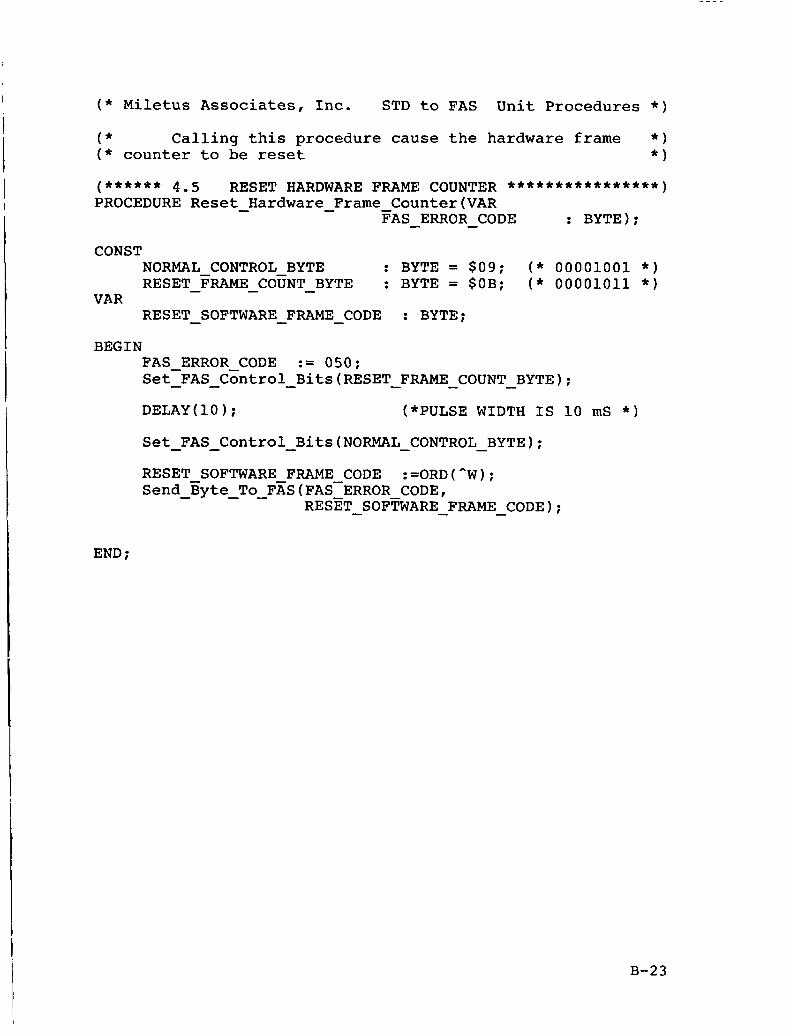
( * Calling this procedure cause the hardware frame * ) ( * counter to be reset * )
(****** 4.5 RESET HARDWARE FRAME COUNTER ****************I PROCEDURE Reset - Hardware - Frame - Counter(VAR
FAS ERROR-CODE : BYTE);
CONST 1
1
NORMAL CONTROL BYTE : BYTE = $09; ( * 00001001 * ) RESET - FRAME - COUNT - BYTE : BYTE = SOB; ( * ooooioii * )
1 VAR RESET - SOFTWARE - FRAME - CODE : BYTE;
BEGIN FAS ERROR CODE := 050; Set-FAS - - CGntrol - Bits (RESET - FRAME - COUNT - BYTE) ; DELAY(10); (*PULSE WIDTH IS 10 mS * )
Set FAS Control Bits(N0RMAL CONTROL BYTE); - - - - - RESET SOFTWARE FRAME CODE :=ORD(^W); Send - Byte - To-FxS(FAS-ERROR CODE,
RESET - SOFTWARE - FRAME - CODE);
END :
B-23
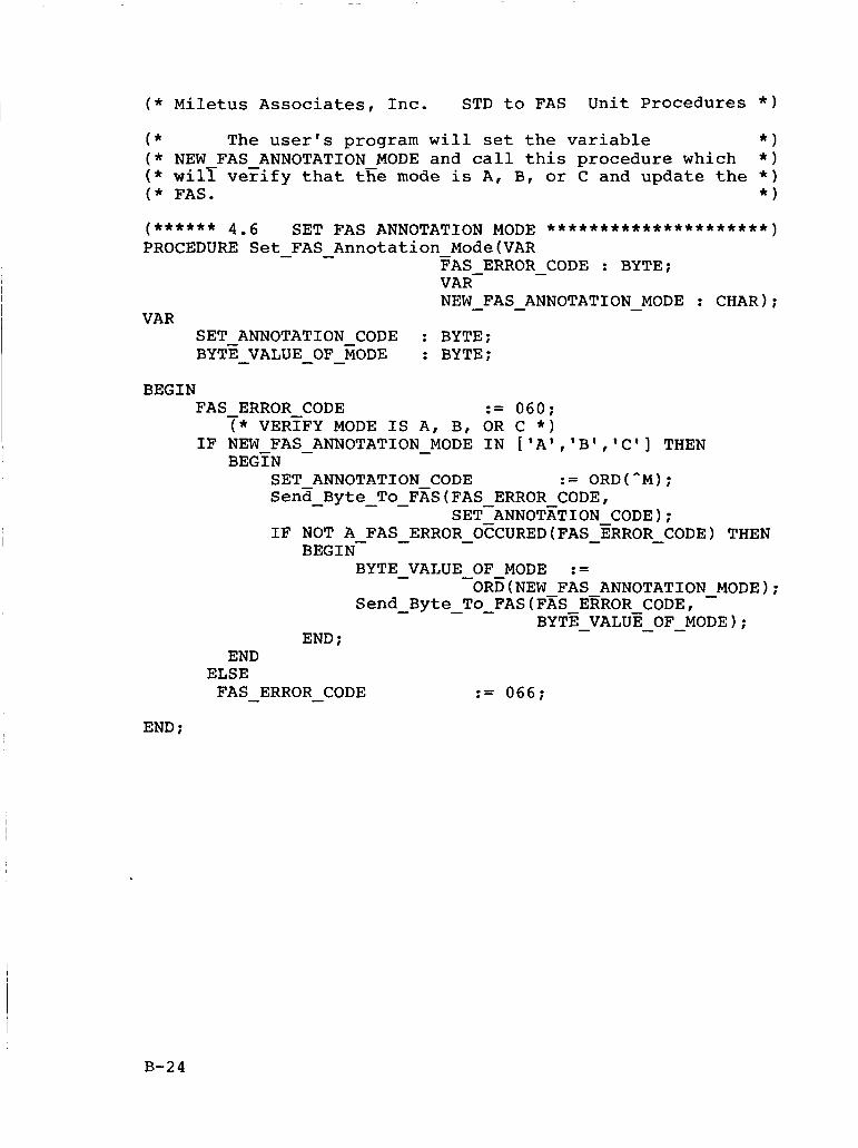
( * Miletus Associates, Inc. STD to FAS Unit Procedures * )
( * The user's program will set the variable * I ( * NEW FAS ANNOTATION MODE and call this procedure which * ) ( * wilr verify that tEe mode is A, B, or C and update the * ) ( * FAS. * )
(****** 4 . 6 SET FAS ANNOTATION MODE . . . . . . . . . . . . . . . . . . . . . . PROCEDURE Set - FAS - Annotation - Mode(VAR
FAS ERROR CODE : BYTE;
NEW - FAS - ANNOTATION - MODE : CHAR); -
VAR-
VAR SET ANNOTATION CODE : BYTE; BYTE - VALUE - - OF MODE : BYTE;
BEGIN FAS - ERROR CODE := 060;
IF NEW FAS - ANNOTATION - MODE IN ['A1,'B','C'] THEN ( * VERTFY MODE IS A, B, OR c * )
BEGTN SET ANNOTATION CODE := ORD(^M); Sena - Byte - - To FxS(FAS ERROR CODE,
SETANNOTATION CODE); IF NOT A FAS - ERROR - O?CURED(FAS - ZRROR - CODE
ORD(NEW FAS ANNOTATION BEGIN-
BYTE - VALUE - OF MODE :=
END ; END
ELSE FAS - ERROR - CODE
END ;
THEN
- MODE ; Send - Byte - - To FAS(FzS ERROR CODE,
BYTE VALUE OF MODE); - - -
:= 066;
B-24
( * Miletus Associates, Inc. STD to FAS Unit Procedures * )
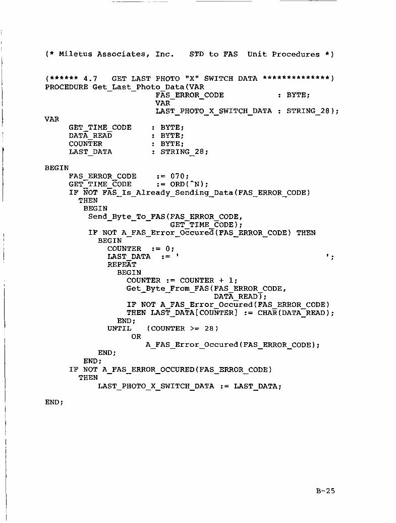
(****** 4 . 7 GET LAST PHOTO "X" SWITCH DATA **************) PROCEDURE Get - Last - Photo Data(VAR
FAS ERROR - CODE : BYTE;
LAST PHOTO X SWITCH - DATA : STRING - 28); VAR-
- - - VAR
GET TIME CODE : BYTE; DATX REAE : BYTE; COUNTER : BYTE; LAST DATA : STRING 28; - -
BEGIN FAS ERROR CODE := 070; GET-TIME EODE := ORD("N); IF EOT FAS - - Is Already-Sending - Data(FAS - ERROR - CODE) THEN BEGIN Send Byte - - To FAS(FAS ERROR-CODE, -
GET-TIME CODE): IF NOT A - FAS - Error - Oburea(FAS7ERROR - - CODE) THEN BEGIN COUNTER := 0; LAST DATA := ' I .
REPEET I
BEGIN COUNTER := COUNTER + 1; Get - Byte From - FAS(FAS ERROR CODE, IF NOT A FAS Error Occcred(FAS ERROR CODE) THEN LAST - DATA[COUNTER]
DATE READT; := CHAE(DATA-READ); -
END ; UNTIL (COUNTER >= 2 8 )
OR A - FAS - Error - Occured(FAS - ERROR-CODE);
END ; END ;
IF NOT A - FAS - ERROR - OCCURED(FAS - ERROR - CODE) THEN
LAST - PHOTO - - X SWITCH - DATA := LAST - DATA; END :
B-25
END ;
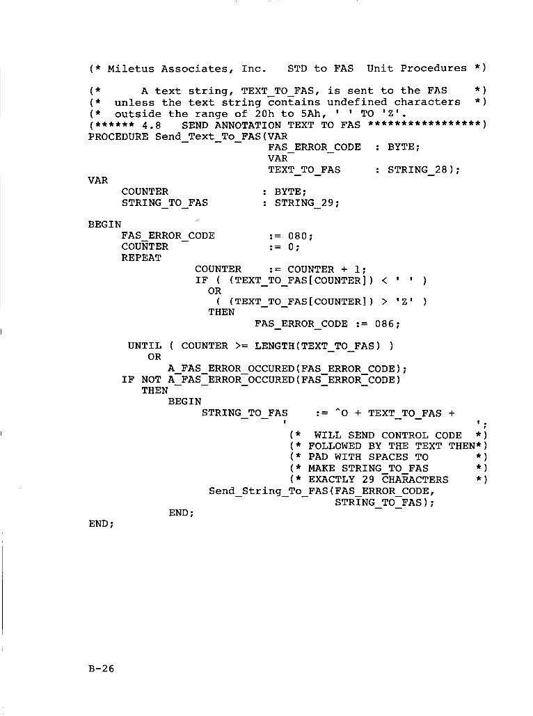
( * WILL SEND CONTROL CODE * ) ( * FOLLOWED BY THE TEXT THEN*) ( * PAD WITH SPACES TO * ) ( * MAKE STRING TO FAS * ) ( * EXACTLY 29 CHA~CTERS * )
STRTNG - - TO-FAS); Send String - - To FAS(FAS ERROR CODE, -
END ;
( * Miletus Associates, Inc. STD to FAS Unit Procedures * )
( * A text string, TEXT TO FAS, is sent to the FAS * ) ( * unless the text string contains undefined characters * ) ( * outside the range of 20h to 5Ah, TO 'Z'.
PROCEDURE Send - Text - - To FAS(VAR (****** 4 . 8 SEND ANNOTATION TEXT TO FAS *****************)
FAS ERROR - CODE : BYTE;
TEXT - TO-FAS : STRING - 2 8 ) ; VAR-
VAR COUNTER : BYTE; STRING - - TO FAS : STRING - 29;
BEGIN FAS ERROR - CODE := 080;
REPEAT COUKTER := 0;
COUNTER := COUNTER + 1; IF ( (TEXT - - TO FAS[COUNTER]) < )
( (TEXT-TO-FAS[COUNTER]) > ' Z ' ) OR
THEN FAS - ERROR - CODE := 086;
UNTIL ( COUNTER >= LENGTH(TEXT TO FAS) ) - - OR
A FAS ERROR OCCURED(FAS ERROR CODE); IF NOT A-FAS-ERROR-OCCURED(FAS-ERROR-CODE) - - - - -
THEN BEGIN
:= ^O + TEXT TO FAS + - - STRING - - TO FAS I I .
I
B-26
( * Miletus Associates, Inc. STD to FAS Unit Procedures * )
( * The variable NEW GMT which is set by the user's * ) * ) ( * program is error checEed and sent to the FAS.
FAS ERROR - CODE : BYTE; VAR- NEW - GMT : STRING 9);
VAR ( * DHHMMS~SS * ) STRING TO FAS : STRING - 29; BINARY-VAEUE : BYTE; COUNTER : BYTE; TENS : BYTE; UNITS : BYTE; ADAPTED NEW GMT : STRING 10; TENS DIEIT : BYTE; UNITS DIGIT : BYTE; DECIMAL - VALUE : BYTE;
- -
BEGIN FAS ERROR-CODE := 090; STRTNG TO FAS := ^p + ' 1 . - -
( * CONVERT 'OD', 'HH', ' M M ' , 'SS', AND 'SS' TO BINARY * ) ( * AND MOVE INTO STRING TO FAS POSITION; UPON ERROR, * ) ( * SET FAS ERROR CODE AED EXIT. ADAPTED NEW GMT- COUNTER- := 1;
* ) := '0' + NEW GMT; - -
REPEAT BEGIN
COUNTER := COUNTER + 1; (*NEXT BYTE * ) TENS := COUNTER * 2 - 3; UNITS := COUNTER * 2 - 2; TENS DIGIT := BYTE(ADAPTED NEW GMT[TENS])
UNITS DIGIT:= BYTE(ADAPTED NEW GMT[UNITS])
- - - - $ 3 0 ;
- $ 3 0 ; - - -
IF (TENS DIGIT > 9) OR (UNITS DIGIT >9) - - THEN
FAS ERROR CODE := 095 - - ELSE
BEGIN DECIMAL VALUE := TENS DIGIT * 10 CASE COUNTER OF 3 : IF DECIMAL VALUE > 23 THEN
- + UNITS DIGIT; -
FAS ERR~R CODE := 095;
FAS ERR~R CODE := 095; 4 : IF DECIMAL VZLUE > 59 THEN 5 : IF DECYMAL VALUE > 59 THEN
FAS ERRER CODE := 095; - - END ;
B-27
( * Miletus Associates, Inc. STD to FAS Unit Procedures * )
END ; IF NOT A - FAS - ERROR - OCCURED(FAS - ERROR - CODE) THEN
STRING TO FAS[COUNTER] := C H A R ~ T E ~ ~ S - DIGIT * 10 + UNITS - DIGIT);
END ; UNTIL (COUNTER >= 6) OR (FAS ERROR CODE = 095); IF NOT A - FAS - ERROR - OCCURED(FAS - ERROR - FODE) THEN
Send - String - - To FAS(FAS ERROR CODE, STRTNG - - TO-FAS);
END ;
B-28
( * Miletus Associates, Inc. STD to FAS Unit Procedures * )
( *
(****** 4.10 PROCEDURE Start FAS Clock(VAR
* ) This procedure starts the GMT clock running
"GO" COMMAND TO START THE CLOCK *************) - -
VAR FAS ERROR CODE : BYTE); - -
START - CLOCK - CODE : BYTE;
BEGIN FAS ERROR CODE := 100; STAFT CLOFK CODE := ORD(^G); Send Byte TG FAS(FAS ERROR CODE, - - - START CLOCK CODE); - -
END ;
B-29
( * Miletus Associates, Inc. STD to FAS Unit Procedures * )
( * The two variables, NUMBER OF PHOTOS - - TO TAKE and * ) ( * INTERVAL BETWEEN PHOTOS, set by the user's program are * ) ( * error ch&k and sent to the FAS. * I
(****** 4.11 SET INTERVALOMETER PARAMETERS ***************I PROCEDURE Set - Intervalometer(VAR
FAS ERROR - CODE : BYTE;
NUMBER OF PHOTOS TO TAKE : BYTE; VAR INTERVAL - BETWEEN - PHOTOS : INTEGER);
VAR- - - - -
VAR SEND INTER - CODE : BYTE; HIGH-BYTE : BYTE; LOW - BYTE : BYTE;
BEGIN FAS ERROR CODE := 110; SEND - INTER CODE IF (NUMBEE OF PHOTOS - - TO TAKE > 2 5 0 )
:= ORD(*Q); - -
OR
OR
OR
THEN
(NUMBER OF PHOTOS TO TAKE < 1 )
(INTERVAL - BETWEEN - PHOTOS > 14400)
(INTERVAL - BETWEEN - PHOTOS < 1)
- - - -
FAS ERROR - CODE := 115; HIGH BYTE- := BYTE(HI(1NTERVAL BETWEEN PHOTOS)); LOW - BYTE := BYTE(INTERVAL - BE~WEEN - PH~TOS);
IF NOT A - FAS - ERROR - OCCURED(FAS - ERROR - CODE) THEN
Send - Byte - - To FAS(FAS ERROR CODE, SEND INTER CODE);
IF NOT A - FAS - ERROR - OCCURED(FAS - ERROR - CODE) THEN
Send Byte - - To FAS(FAS ERROR CODE, - NUEBER O F PHOTOS TO-TAKE);
IF NOT A - FAS - ERROR - OCCURED(FAS-EREOR-CODE) - THEN
Send - Byte - - To FAS(FAS ERROR CODE, HIGE BYTET;
IF NOT A-FAS - ERROR - OCCURED(FAS - ERROR - CODE) THEN
Send - Byte - - To FAS(FAS ERROR-CODE, LOW-BYTE); -
END ;
B-30
( * Miletus Associates, Inc. STD to FAS Unit Procedures * )
( * The FAS will begin taking automatic pictures * )
(****** 4.12 "GO" COMMAND TO START A PHOTO SEQUENCE*******) PROCEDURE Start - Photo - Sequence(VAR VAR
FAS ERROR CODE : BYTE); - - START - PHOTO - SEQUENCE - CODE : BYTE;
BEGIN FAS ERROR CODE := 120; STAFT PHOTO SEQUENCE CODE Send - Eyte - - TE FAS(FAS-ERROR CODE,
:= ORD(^R);
STAFT - PHOTO - SEQUENCE - CODE); END ;
B-31
( * Miletus Associates, Inc. STD to FAS Unit Procedures * )
( * The status of the FAS is returned in the variable * ) ( * named FAS - STATUS - CODE. * )
(****** 4-13 FAS STATUS CODE TO STD . . . . . . . . . . . . . . . . . . . . . . . PROCEDURE Get - FAS - Status(VAR
FAS ERROR CODE, FAS-STATUE - - CODE : BYTE);
CONST FAS - STATUS - CODE - ADDRESS : INTEGER = $104;
BEGIN FAS ERROR CODE := 130; Get-FAS - - Hardware - Data(FAS STATUS CODE ADDRESS,
FAS-STATUS-CODET; - -
END ;
B-32
( * Miletus Associates, Inc. STD to FAS Unit Procedures * )
( * This procedure will stop automatic pictures * I
(****** 4 . 1 4 CANCEL CURRENT PHOTO SEQUENCE ***************) PROCEDURE Cancel Photo Sequence(VAR
VAR
- - FAS ERROR CODE : BYTE); - -
CANCEL PHOTO SEQUENCE CODE : BYTE; - - - BEGIN
FAS ERROR CODE := 140;
Send - Byte - - To-FAS(FAS ERROR CODE, CANCEL PH~TO SEQUENCE CODE := ORD(^S);
CANCEL - PH~TO - SEQUENCE - c
END ;
DE);
B-33
( * Miletus Associates, Inc. STD to FAS Unit Procedures * )
( * The TRUE value of boolean variable * )
( * about to-occur. * ) ( * INTERVAL PRE WARNING FLAG indicates when a picture is * ) -
(****** 4.15 INTERVAL PRE-WARNING FLAG .................... PROCEDURE Get - Photo - Pre - Warning Flag(VAR
FAS ERR~R - CODE INTERVAL PRE WARNING FLAG : BOOLEAN);
: BYTE; VAR-
- - - CONST
FAS PRE WARNING ADDRESS : INTEGER = $103; - - - VAR
PRE - WARNING - DATA - BYTE : BYTE;
BEGIN FAS ERROR CODE := 150; Get-FAS - - Hardware - Data(FAS PRE WARNING ADDRESS,
PRE-WARNING - - DATA - BYTE); INTERVAL PRE WARNING FLAG := - (PRE - WARNTNG - DATA - BYTE AND $01) = $01;
END :
B-34
t
( * Miletus Associates, Inc. STD to FAS Unit Procedures * )
t
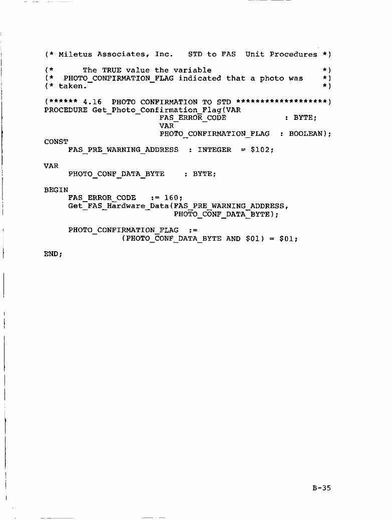
( * The TRUE value the variable * ) ( * * ) ( * taken. * )
PHOTO - CONFIRMATION - FLAG indicated that a photo was
I
(****** 4.16 PHOTO CONFIRMATION TO STD *******************I PROCEDURE Get - Photo - Confirmation Flag(VAR
FAS ERROE - CODE PHOTO - CONFIRMATION - FLAG : BOOLEAN);
: BYTE; VAR-
CONST FAS - PRE - WARNING - ADDRESS : INTEGER = $102;
VAR PHOTO - CONF - DATA - BYTE : BYTE;
BEGIN FAS ERROR CODE := 160; Get-FAS - - Hzrdware - Data(FAS PRE WARNING ADDRESS,
PHOTO - CONF - DATA-BYTE - ;
PHOTO - CONFIRMATION FLAG := (PHOTO-FONF - DATA - BYTE AND $01) = $01;
END ;
B-35
( * Miletus Associates, Inc. STD to FAS Unit Procedures * )
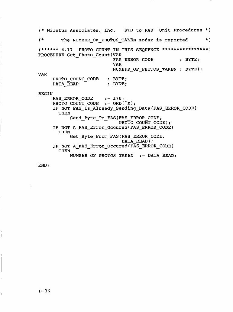
( * The NUMBER - - OF PHOTOS - TAKEN sofar is reported * I
(****** 4.17 PHOTO COUNT IN THIS SEQUENCE ****************) PROCEDURE Get - Photo-Count(VAR
FAS ERROR - CODE : BYTE;
NUMBER - - OF PHOTOS - TAKEN : BYTE); VAR-
VAR PHOTO COUNT - CODE : BYTE; DATA - READ : BYTE;
BEGIN FAS ERROR CODE := 170;
IF NOT FAS - - ys Already - Sending - Data(FAS - ERROR - CODE) PHOTO COUNT CODE := ORD(^X);
THEN Send - Byte - - To FAS(FAS ERROR CODE,
PHOTO COUET CODE); IF NOT A - FAS - Error - Occured(FxS-ERR5R-CODE) THEN
Get - Byte - From - FAS(FAS ERROR CODE, DATX READT;
IF NOT A - FAS - Error - Occured(F% - ERROR - CODE) THEN
NUMBER - - OF PHOTOS - TAKEN := DATA - READ; END ;
B-36
( * Miletus Associates, Inc. STD to FAS Unit Procedures * )
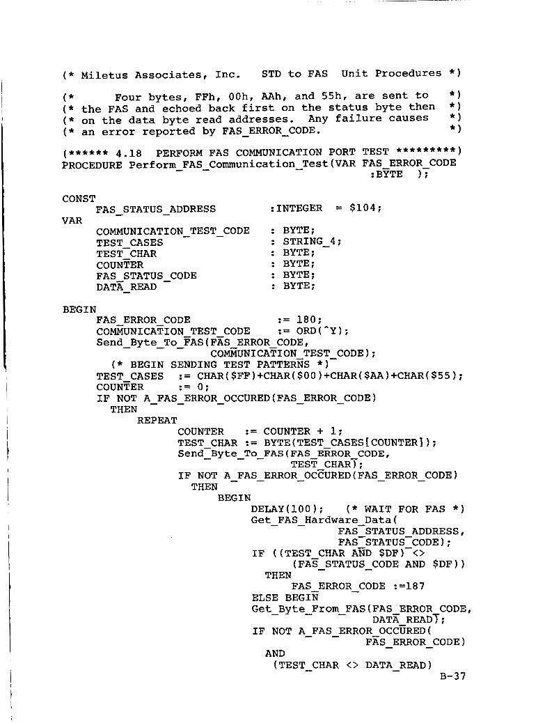
( * Four bytes, FFh, OOh, AAh, and 55h, are sent to * ) ( * the FAS and echoed back first on the status byte then * ) ( * on the data byte read addresses. Any failure causes * )
* ) ( * an error reported by FAS - ERROR - CODE. (****** 4.18 PERFORM FAS COMMUNICATION PORT TEST *********I PROCEDURE Perform FAS - Communication - Test(VAR FAS-ERROR CODE
:BYTE )f
CONST
VAR FAS - STATUS - ADDRESS :INTEGER = $104;
COMMUNICATION - TEST - CODE : BYTE;
TE s T-CHAR : BYTE: COUNTER : BYTE; FAS STATUS CODE : BYTE; DATX READ : BYTE;
: STRING 4; TEST CASES -
- -
BEGIN FAS ERROR CODE := 180;
Send Byte To FAS(FAS ERROR CODE, COMNICATION TEST CODE := ORD(^Y);
( * BEGIN SENDING TEST PATTER% * I - - -
COfiUNICA?;ION TEST-CODE);
TEST CASES := CHAR($FF)+CHAR($OO)+CHAR($AA)+CHAR($55);
IF NOT A FAS ERROR OCCURED(FAS ERROR CODE) COUNTER := 0;
- - - - - THEN
REPEAT COUNTER := COUNTER + 1; TEST CHAR := BYTE(TEST CASES[COUNTER] 1; Send-Byte To FAS(FAS ERROR CODE, - - - TEST CHART; IF NOT A FAS ERROR OCEURED(FAS ERROR CODE) - - - - - THEN
BEGIN DELAY(100); ( * WAIT FOR FAS * ) Get FAS Hardware Data(
IF ((TEST CHAR A ~ D $DF)-<>
- - FAS-STATUS ADDRESS, FAS-STATUS-CODE);
FA^ STATUS CODE AND $DF)) - - THEN
FAS ERROR CODE :=187
Get Byte From FAS(FAS ERROR CODE,
- ELSE BEGIN
IF NOT A FAS ERROR OCC~RED( - - - DATA READT;
- - FAS ERROR CODE) - -
AND (TEST CHAR <> DATA READ) - -
B-37
( * Miletus Associates, Inc. STD to FAS Unit Procedures * )
THEN FAS - ERROR - CODE := 188
END ; END ;
UNTIL
OR (COUNTER >= 4 )
A FAS - ERROR - OCCURED(FAS - ERROR - CODE); - END :
B-38
I
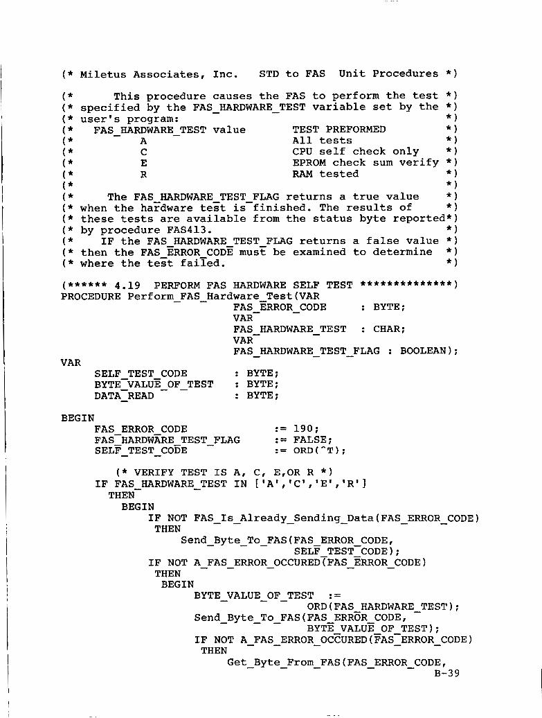
Miletus Associates, Inc. STD to FAS Unit Procedures * )
This procedure causes the FAS to perform the test * ) specified by the FAS HARDWARE TEST variable set by the * ) - - user's program: * ) FAS - HARDWARE - TEST value TEST PREFORMED * )
A All tests * ) C CPU self check only * I E EPROM check sum verify * ) R RAM tested * )
* ) The FAS HARDWARE TEST FLAG returns a true value * )
when the haydware test is-finished. The results of * ) these tests are available from the status byte reported*) by procedure FAS413. * )
IF the FAS HARDWARE TEST FLAG returns a false value * ) then the FAS ERROR CODE must be examined to determine * )
where the test faiied. * I ( ****** 4.19 PERFORM FAS HARDWARE SELF TEST **************I PROCEDURE Perform FAS Hardware Test(VAR - -
FAS ERROR - CODE : BYTE;
FAS HARDWARE TEST : CHAR;
FAS HARDWARE TEST FLAG : BOOLEAN);
VAR-
VAR- -
- - - VAR
SELF TEST CODE : BYTE;
DATA-READ - : BYTE; BYTE-VALUE OF TEST : BYTE; - -
BEGIN FAS ERROR CODE := 190; FAS-HARDW~RE TEST - FLAG SELF - TEST - COEE
:= FALSE; := ORD(^T);
( * VERIFY TEST IS A, C, E,OR R * ) IF FAS HARDWARE - TEST IN ['A','C','E','R'] THEN- BEGIN
IF NOT FAS Is Already Sending Data(FAS ERROR CODE)
SELF TEST-CODE);
- - - - - - THEN
Send Byte To FAS(FAS ERROR CODE,
IF NOT A FAS ERROR OCCUREDTFAS ERROR CODE) - - -
- - - - - THEN BEGIN
BYTE VALUE OF TEST :=
Send Byte To FAS(FAS ERRoR CODE,
IF NOT A FAS ERROR OCFURED(FAS-ERROR CODE)
- - - ORD(FAS HARDWARE TEST); -
- - - BYTE VALUE OF TEST); - - - - -
THEN Get Byte From FAS(FAS ERROR CODE, - - - - -
B-39
( * Miletus Associates, Inc. STD to FAS Unit Procedures * )
DATA READ) ; IF NOT A - FAS - Error - Occured(FAS - ERROR - CODE) THEN
FAS - HARDWARE - TEST - FLAG := TRUE; END :
END ELSE FAS - ERROR - CODE := 196;
END ;
B-40
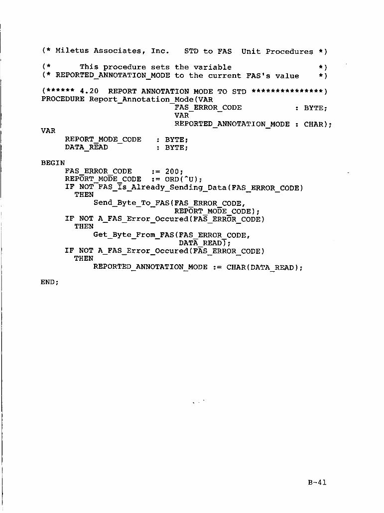
( * Miletus Associates, Inc. STD to FAS Unit Procedures * )
( * This procedure sets the variable * ) ( * REPORTED - ANNOTATION - MODE to the current FAS's value * )
(****** 4.20 REPORT ANNOTATION MODE TO STD ***************I PROCEDURE Report Annotation Mode(VAR
: BYTE; - -
FAS ERROR CODE - VAR-
VAR REPORTED ANNOTATION MODE : CHAR); - -
REPORT MODE - CODE : BYTE; DATA - READ : BYTE;
BEGIN FAS ERROR CODE := 200; REPERT MOEE CODE := ORD(^U); IF NOT-FAS I s Already Sending Data(FAS ERROR CODE) - - - - - - THEN
Send Byte To FAS(FAS ERROR CODE, - - - REPERT MOEE CODE); IF NOT A FAS Error Occured(FA5 ERRoR CODE) - - - - - THEN
Get-Byte From FAS(FAS ERROR CODE, - - DATA READT; IF NOT A FAS Error Occured(FAS-ERROR CODE) - - - - THEN
REPORTED ANNOTATION MODE := CHAR(DATA READ); - - - END ;
B-41
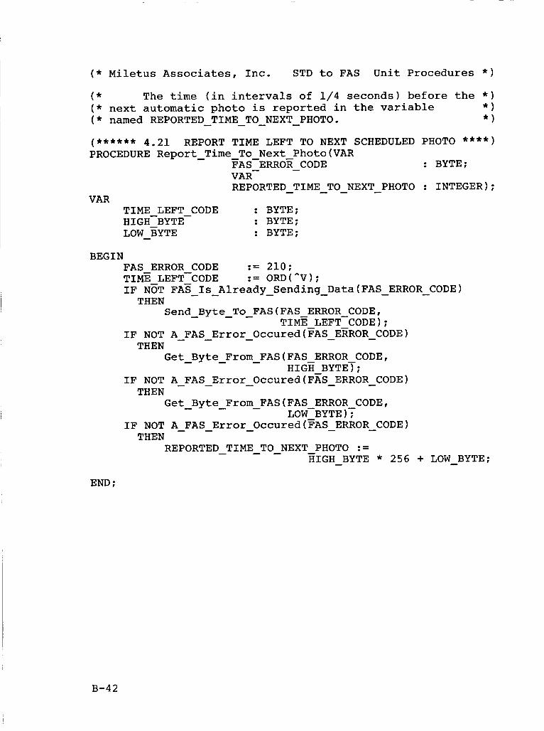
( * Miletus Associates, Inc. STD to FAS Unit Procedures * )
( * The time (in intervals of 1/4 seconds) before the * )
* ) ( * next automatic photo is reported in the variable * ) ( * named REPORTED-TIME - TO-NEXT-PHOTO.
(****** 4.21 REPORT TIME LEFT TO NEXT SCHEDULED PHOTO ****I PROCEDURE Report - Time - To-Next-Photo(VAR
FAS ERROR CODE : BYTE;
REPORTED - TIME - - TO NEXT - PHOTO : INTEGER); -
VAR-
VAR TIME LEFT CODE : BYTE; HIGH-BYTE- : BYTE; LOW - BYTE : BYTE;
BEGIN FAS ERROR CODE := 210; TIME LEFT-CODE := ORD("V); IF NOT FA5 - - Is Already - Sending - Data(FAS - ERROR - CODE) THEN
Send - Byte - - To FAS(FAS ERROR-CODE, TIME LEFT CODE) ;
IF NOT A-FAS - Error - Occured(FAS - ERROR - CODE) THEN
Get - Byte - From - FAS(FAS ERROR CODE, HIGE BYTET;
IF NOT A-FAS-Error - Occured(Fk - ERROR - CODE) THEN
Get - Byte - From - FAS(FAS-ERROR CODE, LOW BYTE )f
IF NOT A - FAS - Error - Occured(gAS - ERROR - CODE) THEN
REPORTED TIME TO NEXT - PHOTO := - - - HIGH BYTE * 256 + LOW - BYTE; -
END ;
B-42
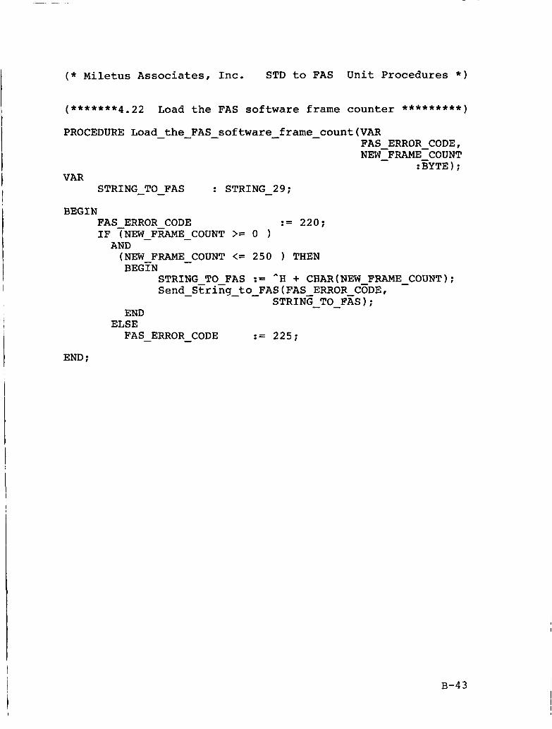
( * Miletus Associates, Inc. STD to FAS Unit Procedures * )
(*******4.22 Load the FAS software frame counter *********I
PROCEDURE Load - the - FAS - software - frame - count(VAR FAS ERROR CODE,
:BYTE); NEW-FRAME-COUNT - -
VAR : STRING 29; STRING - - TO FAS -
BEGIN FAS ERROR CODE := 220; IF TNEW-F~E - COUNT >= o AND (NEW-FRAME - COUNT <= 250 THEN BEGIN
STRING TO FAS := ^H + CHAR(NEW FRAME - COUNT); Send - StriEg - - to FAS(FAS ERROR-CEDE,
STRINE - - TO FAS); END
FAS - ERROR - CODE := 225; ELSE
END ;
B-43
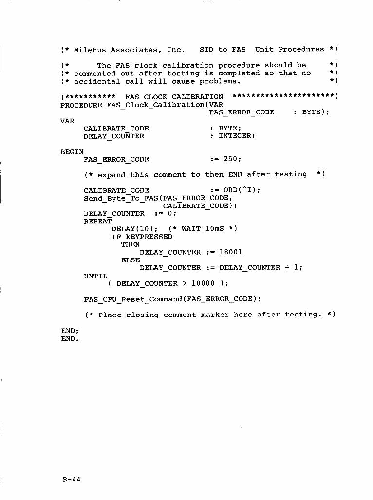
( * Miletus Associates, Inc. STD to FAS Unit Procedures * )
( * The FAS clock calibration procedure should be * ) ( * commented out after testing is completed so that no * ) ( * accidental call will cause problems. * )
BEGIN FAS ERROR CODE - - := 250;
( * expand this comment to then END after testing
Send - Byte-To - - FAS(FAS ERROR-CODE,
DELAY COUNTER := 0;
* )
CALIBRATE CODE := ORD(^I);
CAL~BRATE-CODE);
REPEAT DELAY(10); ( * WAIT lOmS * ) IF KEYPRESSED THEN
ELSE DELAY - COUNTER := 18001
DELAY - COUNTER := DELAY - COUNTER + 1;
( DELAY - COUNTER > 18000 1; UNTIL
FAS - CPU - Reset - Command(FAS - ERROR - CODE); ( * Place closing comment marker here after testing. * )
END ; END.
B-44
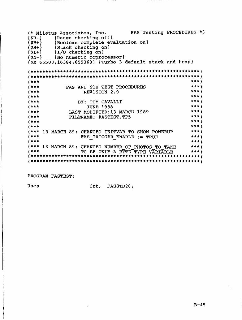
( * Miletus Associates, Inc. FAS Testing PROCEDURES * ) { SR- 1 {Range checking off) ESB+l {Boolean complete evaluation on} {SS+l {Stack checking on} {$I+) {I/O checking on} { SN- 1 {No numeric coprocessor) {SM 65500,16384,655360) {Turbo 3 default stack and heap)
. . . . . . . . . . . . . . . . . . . . . . . . . . . . . . . . . . . . . . . . . . . . . . . . . . . . . . . . . . .
. . . . . . . . . . . . . . . . . . . . . . . . . . . . . . . . . . . . . . . . . . . . . . . . . . . . . . . . . . . ( * * * ***) ( * * * FAS AND STD TEST PROCEDURES ***) ( *** REVISION 2.0 *** ) (*** *** ) ( *** BY: TOM CAVALLI *** ) ( * * * JUNE 1988 *** ) ( * * * LAST MODIFIED:13 MARCH 1989 ***) ( *** FILENAME: FASTEST.TP5 ***) ( * * * ***) ( *** * * * ) ( *** 13 MARCH 89: CHANGED INITVAR TO SHOW POWERUP *** ) ( *** FAS TRIGGER ENABLE := TRUE ***) ( *** *** ) ( * * * 13 MARCH 89: CHANGED NUMBER OF PHOTOS TO TAKE *** ) ( *** TO BE ONLY A BYTETYPE VXRIXBLE *** ) . . . . . . . . . . . . . . . . . . . . . . . . . . . . . . . . . . . . . . . . . . . . . . . . . . . . . . . . . . . . . . . . . . . . . . . . . . . . . . . . . . . . . . . . . . . . . . . . . . . . . . . . . . . . . . . . . . . . . .
- -
PROGRAM FASTEST:
Uses Crt, FASSTD20;
B-45
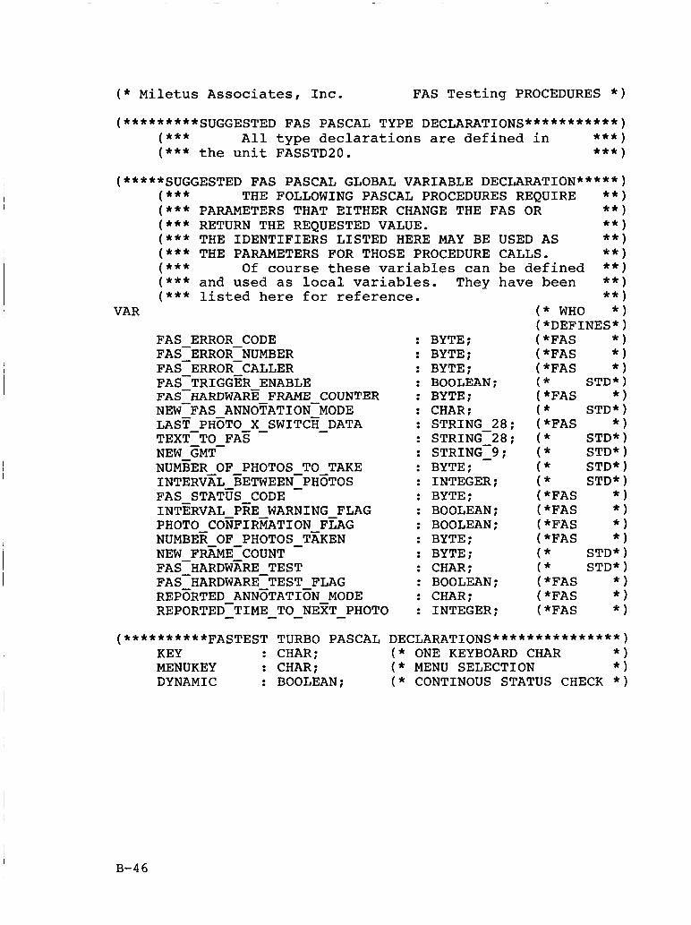
( * Miletus Associates, Inc. FAS Testing PROCEDURES * )
(*********SUGGESTED FAS PASCAL TYPE DECLARATIONS***********) ( * * * All type declarations are defined in *** ) ( * ** the unit FASSTD2O. *** )
(*****SUGGESTED FAS PASCAL GLOBAL VARIABLE DECLARATION*****) ( *** THE FOLLOWING PASCAL PROCEDURES REQUIRE * * ) ( * * * PARAMETERS THAT EITHER CHANGE THE FAS OR ** 1 ( * * * RETURN THE REQUESTED VALUE. ( *** THE IDENTIFIERS LISTED HERE MAY BE ( * * * THE PARAMETERS FOR THOSE PROCEDURE ( * * * Of course these variables can ( * * * and used as local variables. They ( *** listed here f o r reference.
VAR
FAS ERROR CODE FAS-ERRORINUMBER FAS-ERROR CALLER FAS-TRIGGER ENABLE NEW-FAS ANNOTATION-MODE LAST PHETO x SWITCH - DATA TEXT-TO FAS - NEW GMT- NUMBER OF PHOTOS TO TAKE INTERVXL BETWEEN-PH~TOS - FAS STATUS CODE INTERVAL PEE WARNING FLAG PHOTO CONFIGTION FEAG NUMBER OF PHOTOS - TEKEN NEW FRZME-COUNT FAS-HARDWARE TEST FAS-HARDWARE-TEST FLAG REPERTED ANNETATIEN MODE REPORTED-TIME - - - TO NEZT - PHOTO
FASHARDWARE FRAME COUNTER
: BYTE; : BYTE; : BYTE; : BOOLEAN; : BYTE: : CHAR; : STRING 28; : STRING-28;
: BYTE; : INTEGER; : BYTE; : BOOLEAN: : BOOLEAN: : BYTE; : BYTE: : CHAR; : BOOLEAN: : CHAR: : INTEGER:
: STRING^; -
( * STD*)
( * STD*)
( * STD*) ( * STD* ( * STD*) ( * STD* 1
( *FAS * )
( *FAS * I
(*FAS * ) ( *FAS * ) (*FAS * ) ( *FAS * )
( *FAS * ) (*FAS * ) (*FAS * )
( * STD*) ( * STD*
** 1 USED AS ** 1 CALLS. ** 1 be defined * * ) have been * * )
** 1 ( * WHO * ) (*DEFINES*) (*FAS * ) (*FAS * ) (*FAS * )
(**********FASTEST TURBO PASCAL DECLARATIONS***************) KEY : CHAR; ( * ONE KEYBOARD CHAR * ) MENUKEY : CHAR: ( * MENU SELECTION * ) DYNAMIC : BOOLEAN; ( * CONTINOUS STATUS CHECK * )
B-46
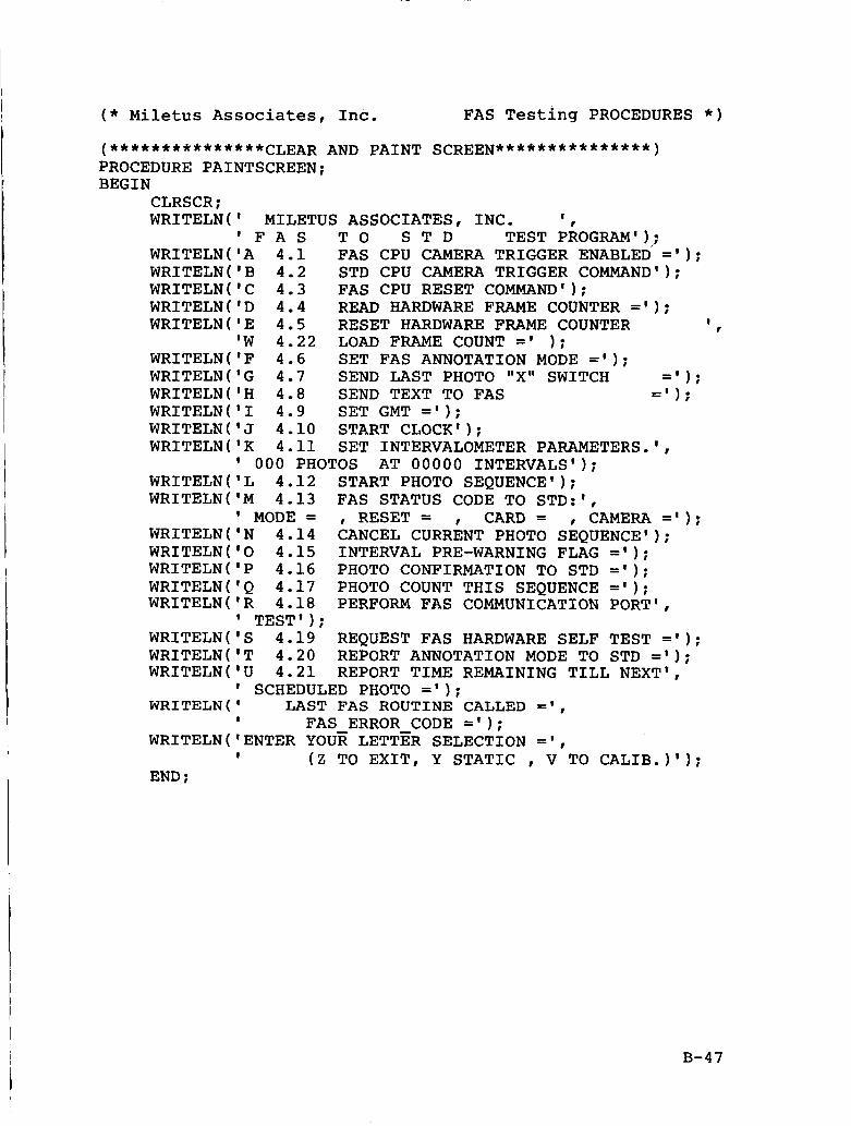
I I
( * Miletus Associates, Inc. FAS Testing PROCEDURES * )
1
I
(***************CLEAR AND PAINT SCREEN***************) PROCEDURE PAINTSCREEN; BEGIN
CLRSCR; WRITELN(' MILETUS ASSOCIATES, INC. I
WRITELN('A 4.1 FAS CPU CAMERA TRIGGER ENABLED ='I; WRITELN('B 4.2 STD CPU CAMERA TRIGGER COMMAND'); WRITELN('C 4.3 FAS CPU RESET COMMAND'); WRITELN('D 4.4 READ HARDWARE FRAME COUNTER = ' I ; WRITELN('E 4.5 RESET HARDWARE FRAME COUNTER I I
WRITELN('F 4.6 SET FAS ANNOTATION MODE = ' I ;
' F A S T O S T D TEST PkOGRAM' 1,;
'W 4.22 LOAD FRAME COUNT =' 1;
WRITELN( 'G 4.7 SEND LAST PHOTO "X" SWITCH =' ) ; WRITELN('H 4.8 SEND TEXT TO FAS =I ) ; WRITELN('1 4.9 SET GMT = ' I ; WRITELN('J 4.10 START CLOCK'); WRITELN('K 4.11 SET INTERVALOMETER PARAMETERS,',
000 PHOTOS AT 00000 INTERVALS'); WRITELN('L 4.12 START PHOTO SEQUENCE'); WRITELN('M 4.13 FAS STATUS CODE TO STD:',
WRITELN('N 4.14 CANCEL CURRENT PHOTO SEQUENCE');
WRITELN('P 4.16 PHOTO CONFIRMATION TO STD = ' I ; WRITELN('Q 4.17 PHOTO COUNT THIS SEQUENCE = ' I ;
I MODE = , RESET = , CARD = , CAMERA = ' I ;
WRITELN('0 4.15 INTERVAL PRE-WARNING FLAG = I ) ;
WRITELNVR 4.18 PERFORM FAS COMMUNICATION PORT',
WRITELN~T 4.20 REPORT ANNOTATION MODE TO STD = I ) ;
' TEST'); WRITELN('S 4.19 REQUEST FAS HARDWARE SELF TEST = ' I ;
WRITELN('U 4.21 REPORT TIME REMAINING TILL NEXT',
WRITELN ( LAST FAS ROUTINE CALLED = I ,
' SCHEDULED PHOTO =I ) ;
I FAS ERROR CODE ='I;
I ( Z TO EXIT, Y STATIC , V TO CALIB.)'); WRITELNVENTER YOUR LETTER SELECTION = I ,
END ;
I
B-47
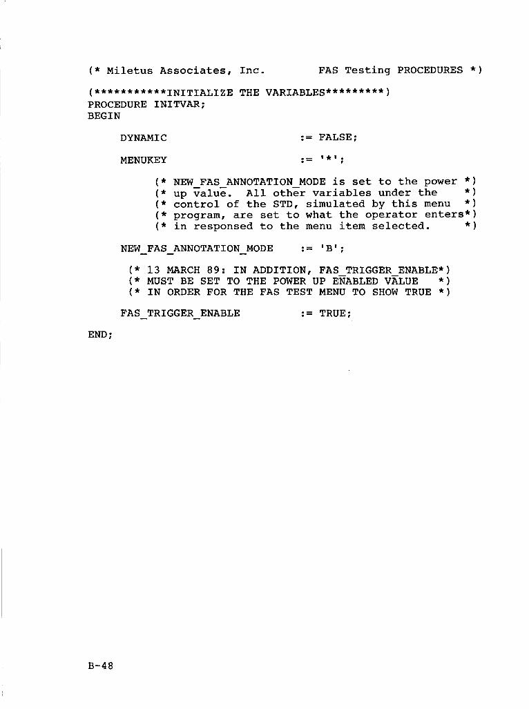
( * Miletus Associates, Inc. FAS Testing PROCEDURES * )
(***********INITIALIZE THE VARIABLES*********) PROCEDURE INITVAR; BEGIN
DYNAMIC := FALSE:
( * NEW FAS ANNOTATION MODE is set to the power * )
( * control of the STD, simulated by this menu * ) ( * program, are set to what the operator enters*)
( * up value. All oth& variables under the * )
( * in responsed to the menu item selected. * I a - IBl. .- NEW FAS - ANNOTATION - MODE -
( * 13 MARCH 89: IN ADDITION, FAS TRIGGER ENABLE*) ( * MUST BE SET TO THE POWER UP EfABLED VZLUE * ) ( * IN ORDER FOR THE FAS TEST MENU TO SHOW TRUE * )
FAS - TRIGGER - ENABLE := TRUE;
END :
B-48
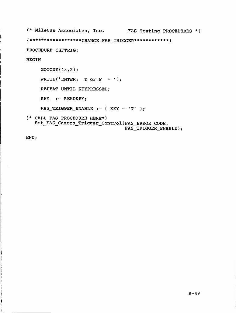
( * Miletus Associates, Inc. FAS Testing PROCEDURES * )
(******************CHANGE FAS TRIGGER************)
PROCEDURE CHFTRIG;
BEGIN
GOTOXY(43,2);
WRITE('ENTER: T or F = ' 1 ;
REPEAT UNTIL KEYPRESSED;
KEY := READKEY;
FAS TRIGGER ENABLE := ( KEY = 'T' ) ; - - ( * CALL FAS PROCEDURE HERE*)
Set FAS Camera Trigger Control(FAS ERROR CODE, - - - - FAS-TRIGGER ENABLE); - - END ;
B-49
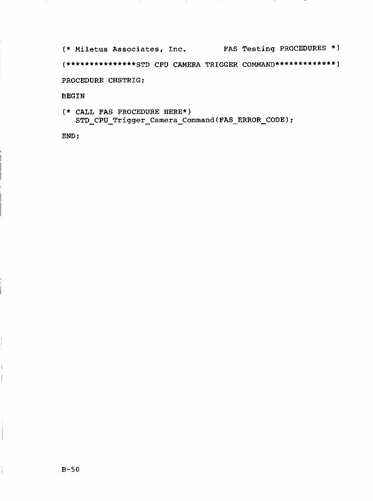
( * Miletus Associates, Inc. FAS Testing PROCEDURES * )
PROCEDURE CHSTRIG;
BEGIN
( * CALL FAS PROCEDURE HERE*) STD - CPU - Trigger - Camera - Command(FAS - ERROR - CODE);
END ;
B-50
( * Miletus Associates, Inc. FAS Testing PROCEDURES * )
PROCEDURE CHFRESET;
BEGIN
( * CALL FAS PROCEDURE HERE*) FAS CPU Reset Command(FAS - ERROR - CODE); - - -
( * DOES THIS RESET THE ANNOTATION MODE TO B? and * ) ( * ENABLE THE FAS CAMERA CONTROL? YES, IT does. So: * I
NEW FAS ANNOTATION MODE := 'B'; - - - END ;
B-51
( * Miletus A s s o c i a t e s , Inc . FAS T e s t i n g PROCEDURES * )
PROCEDURE CHFFCNT;
BEGIN
( * CALL FAS PROCEDURE HERE*) Read - H a r d w a r e - F r a m e - C o u n t e r ( F A S ERROR CODE,
FAS-HARDWARE - - FRAME - COUNTER);
G O T O X Y ( 4 0 , 5 ) ;
CLREOL;
WRITE (FAS HARDWARE FRAME COUNTER 1 ; - - - END ;
B-52
( * Miletus Associates, Inc. FAS Testing PROCEDURES * )
PROCEDURE CHFFRESET;
BEGIN
( * CALL FAS PROCEDURE HERE*) Reset - Hardware - Frame - Counter(FAS - ERROR - CODE);
END ;
B-53
( * Miletus Associates, Inc. FAS Testing PROCEDURES * )
PROCEDURE CHFMODE;
BEGIN
GOTOXY ( 36,7 ;
WRITE('ENTER: A, B, or C');
REPEAT UNTIL KEYPRESSED;
KEY := READKEY;
GOTOXY(36,7):
WRITE(KEY,' ' 1 ;
NEW - FAS - ANNOTATION - MODE := KEY:
( * CALL FAS PROCEDURE HERE*) Set - FAS - Annotation - Mode(FAS ERROR CODE,
NEW-FAS - - AKNOTATION - MODE);
END ;
B-54
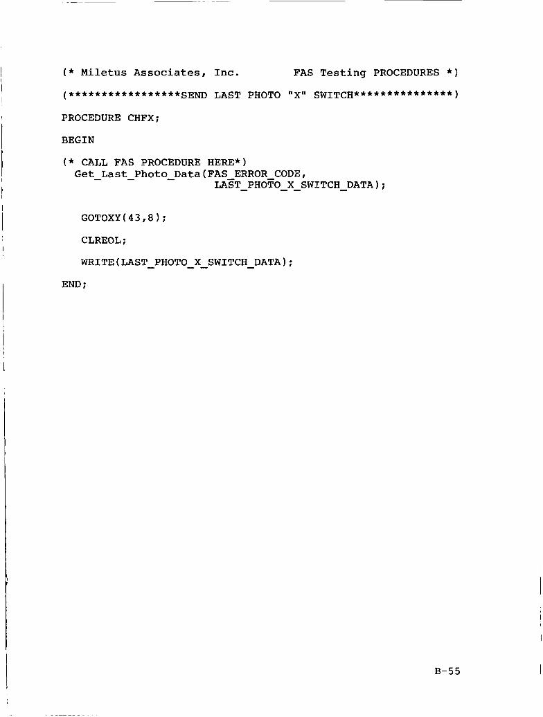
PROCEDURE CHFX;
BEGIN
( * CALL FAS PROCEDURE HERE*) Get - Last - Photo - Data(FAS ERROR CODE,
LAZT - PHOFO - - X SWITCH - DATA);
CLREOL ;
WRITE(LAST - PHOTO - - X SWITCH - DATA);
END ;
B-55
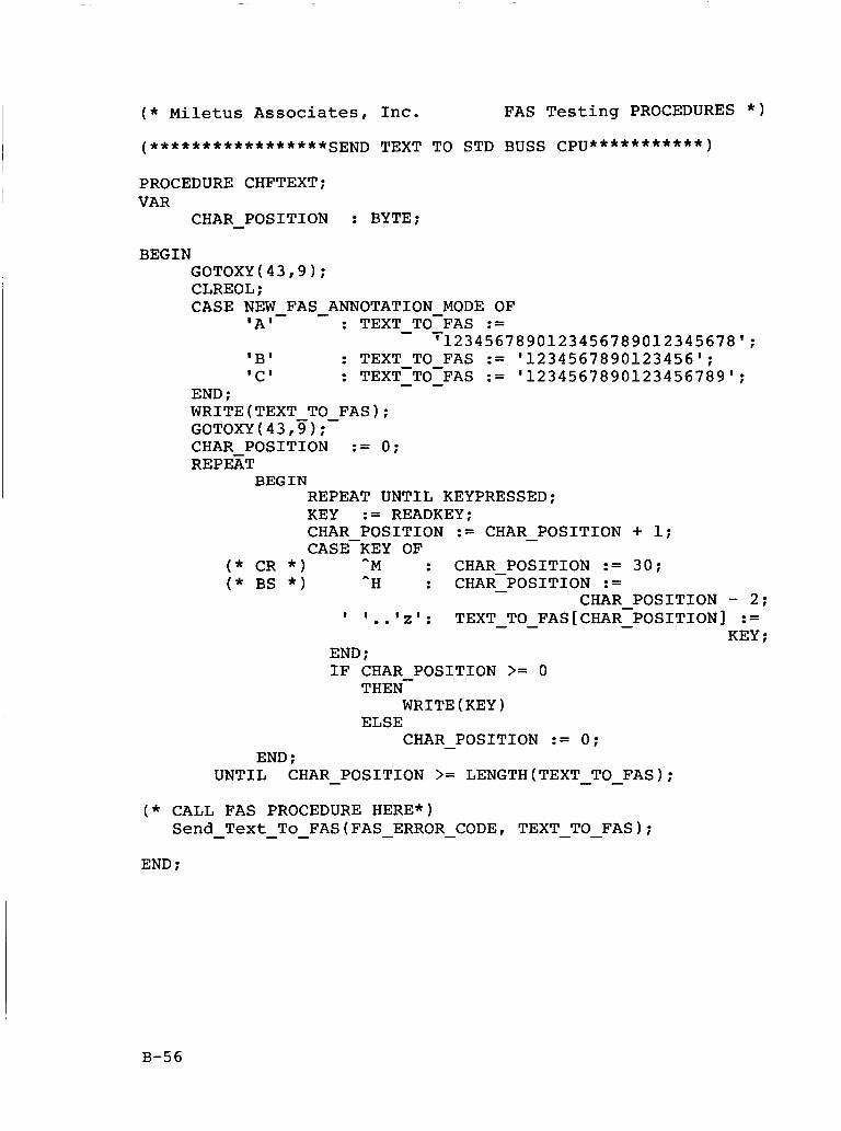
( * Miletus Associates, Inc. FAS Testing PROCEDURES * )
PROCEDURE CHFTEXT; VAR
CHAR - POSITION : BYTE;
BEGIN GOTOXY(43,9); CLREOL; CASE NEW - FAS - ANNOTATION MODE OF
: TEXT TO-FAS := - - 'A'
'B' : TEXT TO FAS := '1234567890123456'; 'C' : TEXT-TO-FAS - - := '1234567890123456789';
'1234567890123456789012345678';
END ; wRITE(TEXT TO FAS); GOTOXY(43,y) ;- CHAR POSITION := 0; REPEXT
BEGIN REPEAT UNTIL KEYPRESSED; KEY := READKEY; CHAR POSITION := CHAR - POSITION + 1; CASEKEY OF
( * CR * ) *M : CHAR POSITION := 30; ( * BS * ) ^H : CHAR-POSITION - :=
CHAR POSITION - 2; KEY ;
' I . . '2' : TEXT - - TO FASCCHAR-POSITION] - :=
END ; IF CHAR POSITION >= 0
THEN- WRITE(KEY)
CHAR - POSITION := 0; ELSE
END : UNTIL CHAR POSITION >= LENGTH(TEXT TO FAS); - - -
( * CALL FAS PROCEDURE HERE*) Send Text To FAS(FAS ERROR CODE, TEXT TO FAS); - - - - - - -
END ;
B-56
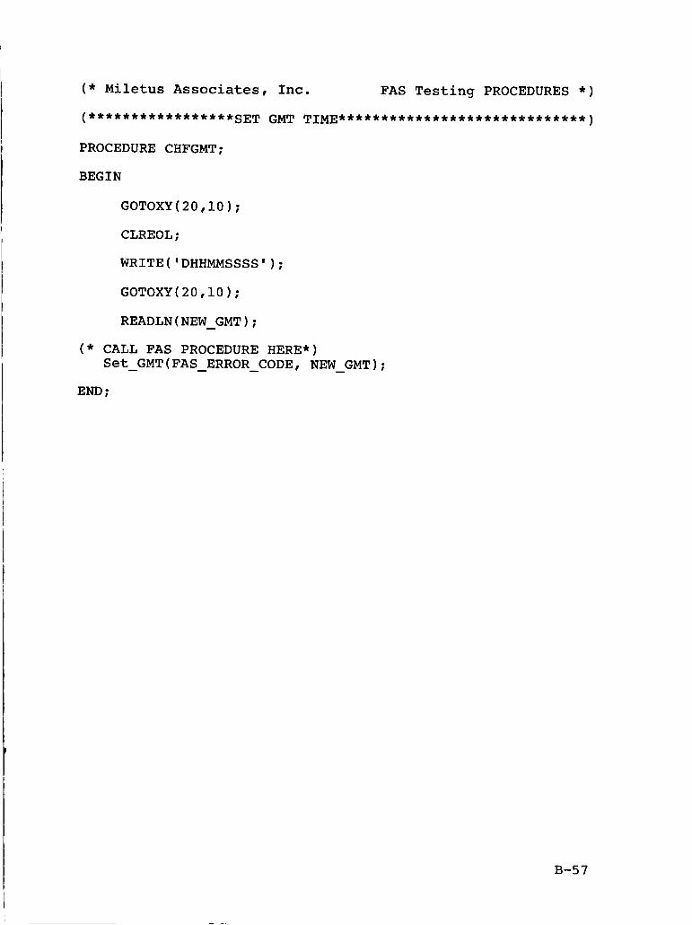
( * Miletus Associates, h c . FAS Testing PROCEDURES * )
(*****************SET GMT TIME*****************************)
PROCEDURE CHFGMT;
BEGIN
GOTOXY(20,lO);
CLREOL;
WRITE('DHHMMSSSS');
GOTOXY(20,lO);
READLN(NEW GMT); - ( * CALL FAS PROCEDURE HERE*)
Set GMT(FAS ERROR CODE, NEW GMT); - - - - END ;
B-57
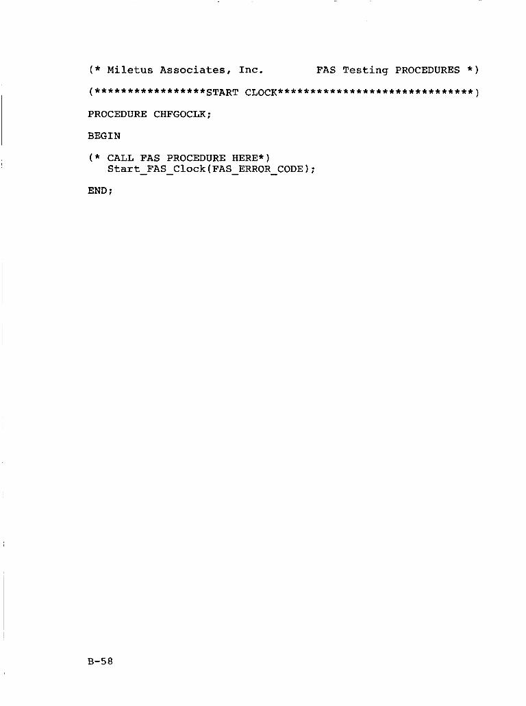
( * Miletus Associates, Inc. FAS Testing PROCEDURES * )
PROCEDURE CHFGOCLK;
BEGIN
( * CALL FAS PROCEDURE HERE*) Start FAS Clock(FAS ERROR CODE); - - - -
END :
B-58
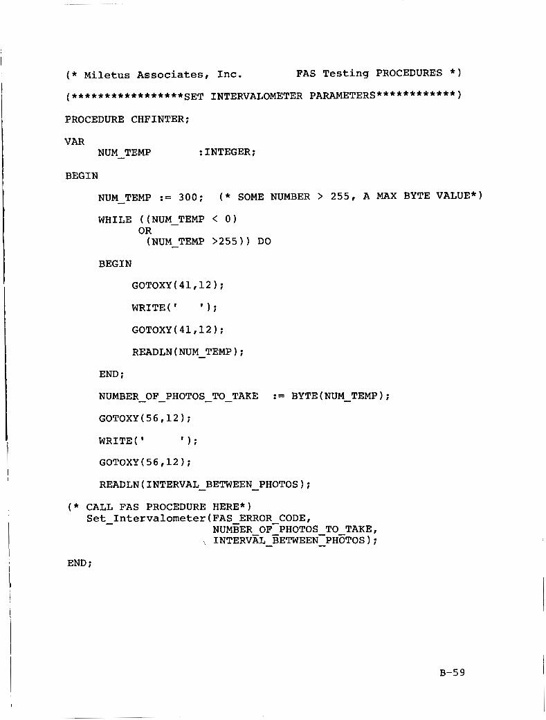
( * Miletus Associates, Inc. FAS Testing PROCEDURES * )
PROCEDURE CHFINTER;
VAR NUM - TEMP : INTEGER;
BEGIN
NUM - TEMP := 300; ( * SOME NUMBER > 255, A MAX BYTE VALUE*)
WHILE ((NUM - TEMP < 0) OR (NUM - TEMP >255)) DO
BEGIN
GOTOXY(41,12);
READLN(NUM TEMP); - END ;
NUMBER - - OF PHOTOS-TO - TAKE := BYTE(NUM-TEMP);
GOTOXY(56,12);
WRITE( I I ) ;
GOTOXY(56,12);
READLN(1NTERVAL BETWEEN PHOTOS); - - ( * CALL FAS PROCEDURE HERE*)
Set - Intervalometer(FAS ERROR CODE, NUMBER OF-PHOTOS TO TAKE,
, INTERV~L - ZETWEEN-PH~TOS); -
END ;
B-59
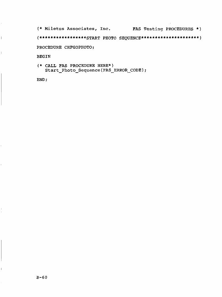
( * Miletus Associates, Inc. FAS Testing PROCEDURES * )
PROCEDURE CHFGOPHOTO;
BEGIN
( * CALL FAS PROCEDURE HERE*) Start - Photo - Sequence(FAS - ERROR-CODE);
END ;
B-60
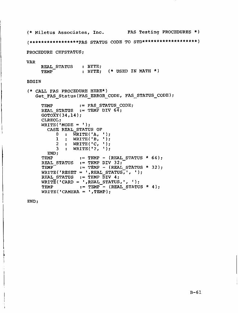
( * Miletus Associates, Inc. FAS Testing PROCEDURES * )
PROCEDURE CHFSTATUS;
VAR REAL STATUS : BYTE; TEMP- : BYTE; ( * USED IN MATH * )
BEGIN
( * CALL FAS PROCEDURE HERE*) Get - FAS - Status(FAS - ERROR - CODE, FAS - STATUS - CODE);
END ;
TEMP := FAS STATUS CODE; REAL STATUS GOTOzY(34,14); CLREOL ;
:= TEMF DIV 6z;
WRITE('M0DE = ' 1 ; CASE REAL STATUS OF
o : KRITE(IA, 1); 1 : WRITE('B, I ) ;
2 : WRITE(IC, I ) ;
3 : WRITE('?, I ) ;
END ; := TEMP - (REAL STATUS * 64); TEMP
REAL STATUS := TEMP DIV 32; TEMP- := TEMP - (REAL STATUS * 32); REAL STATUS
TEMP WRITE('CAMERA = ',TEMP);
-
WRITE( 'RESET = 1 ,REAL STATUS:' , I ) ;
WRITWCARD = ',REAL STATUS,', 1 1 ; := TEMP DIV 4;
:= TEMP-- (REAL STATUS * 4); -
B-61
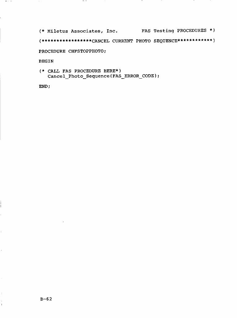
( * Miletus Associates, Inc. FAS Testing PROCEDURES * )
(*****************CANCEL CURRENT PHOTO SEQUENCE************)
PROCEDURE CHFSTOPPHOTO;
BEGIN
( * CALL FAS PROCEDURE HERE*) Cancel - Photo - Sequence(FAS - ERROR - CODE);
END ;
B-62
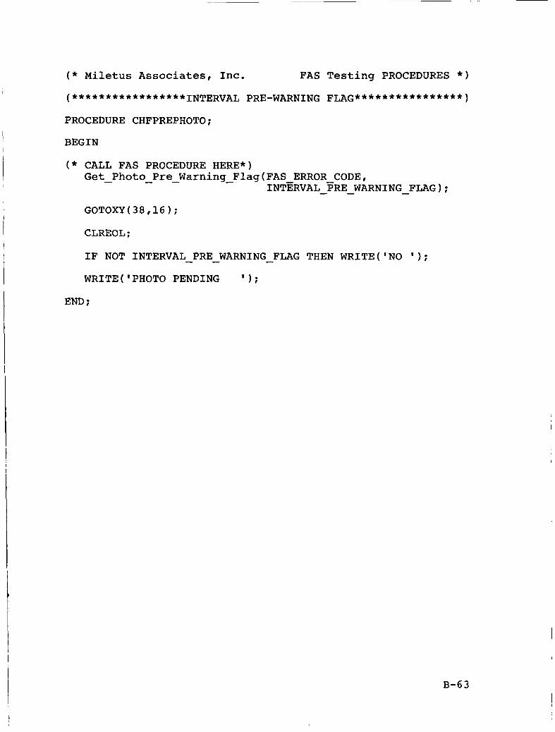
( * Miletus Associates, Inc. FAS Testing PROCEDURES * )
(*****************INTERVAL PRE-WARNING FLAG****************)
PROCEDURE CHFPREPHOTO;
BEGIN
( * CALL FAS PROCEDURE HERE*) Get - Photo - Pre - Warning - Flag(FAS ERROR CODE,
GOTOXY(38,16);
CLREOL;
IF NOT INTERVAL PRE WARNING - FLAG THEN WRITE('N0 ' 1 ;
WRITE('PHOT0 PENDING ' 1 ;
INTERVAL - FRE - WARNING-FLAG);
- -
END ;
B-63
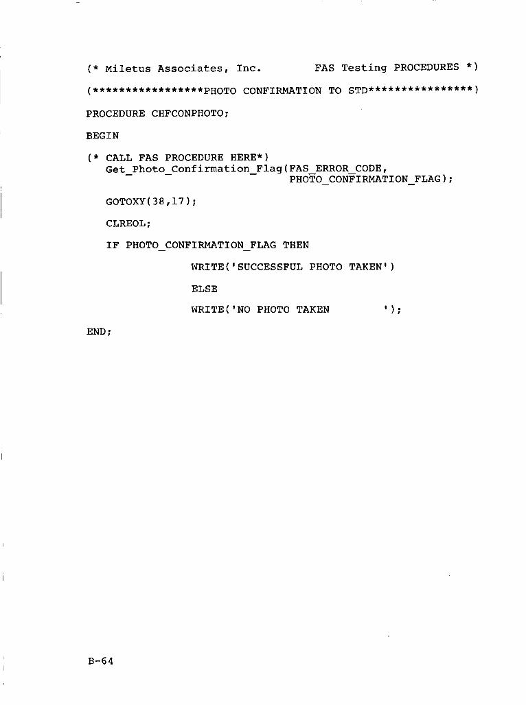
( * Miletus Associates, Inc. FAS Testing PROCEDURES * )
PROCEDURE CHFCONPHOTO;
BEGIN
( * CALL FAS PROCEDURE HERE*) Get - Photo - Confirmation - Flag(FAS ERROR CODE,
PHOTO - CONFIRMATION-FLAG);
CLREOL;
IF PHOTO CONFIRMATION FLAG THEN - - WRITE('SUCCESSFUL PHOTO TAKEN')
ELSE
WRITE('N0 PHOTO TAKEN ' 1:
END ;
B-64
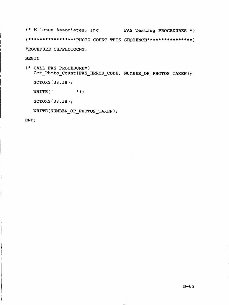
( * Miletus Associates, Inc. FAS Testing PROCEDURES * )
(*****************PHOTO COUNT THIS SEQUENCE****************)
PROCEDURE CHFPHOTOCNT;
BEGIN
( * CALL FAS PROCEDURE*) Get Photo Count(FAS ERROR CODE, NUMBER OF PHOTOS TAKEN);
GOTOXY(38,18);
- - - - - - -
WRITE( I I ) ;
GOTOXY(38,18);
WRITE(NUMBER OF PHOTOS TAKEN); - - - END ;
B-6 5
I
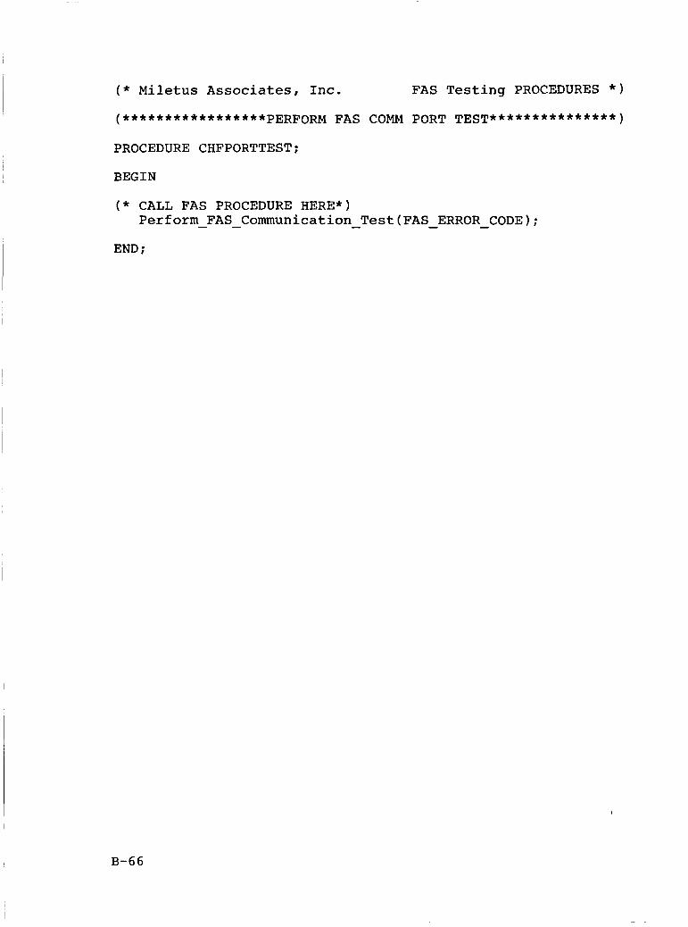
( * Miletus Associates, Inc. FAS Testing PROCEDURES * )
PROCEDURE CHFPORTTEST;
BEGIN
( * CALL FAS PROCEDURE HERE*) Perform - FAS - Communication - Test(FAS - ERROR - CODE);
END ;
B-66
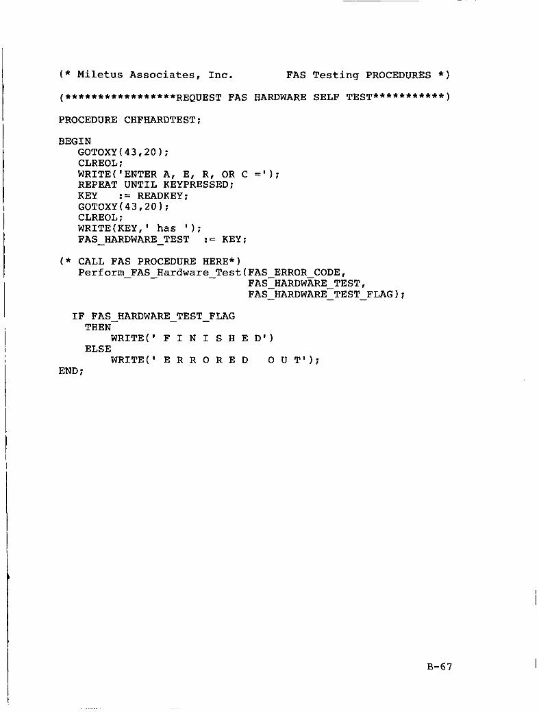
( * Miletus Associates, Inc. FAS Testing PROCEDURES * )
(*****************REQUEST FAS HARDWARE SELF TEST***********)
PROCEDURE CHFHARDTEST;
BEGIN GOTOXY(43,20); CLREOL; WRITE('ENTER A, E, R, OR C = ' I ; REPEAT UNTIL KEYPRESSED; KEY := READKEY; GOTOXY(43,20); CLREOL ; WRITE(KEY,' has ' 1 ; FAS HARDWARE - TEST := KEY; -
( * CALL FAS PROCEDURE HERE*) Perform - FAS - Hardware - Test(FAS ERROR CODE,
FAS-HARDWARE TEST, FAS-HARDWARE-TEST - - - FLAG);
IF FAS HARDWARE TEST FLAG - - THEN-
WRITE(' F I N I S H E D')
WRITE(' E R R 0 R E D 0 U TI); ELSE
END ;
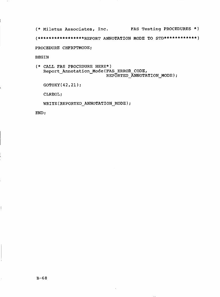
( * Miletus Associates, Inc. FAS Testing PROCEDURES * )
PROCEDURE CHFRPTMODE;
BEGIN
( * CALL FAS PROCEDURE HERE*) Report-Annotation-Mode(FAS ERROR CODE,
REP~RTED - XNNOTATION - MODE); GOTOXY(42,21);
CLREOL;
WRITE(REP0RTED - ANNOTATION - MODE);
END ;
B-68
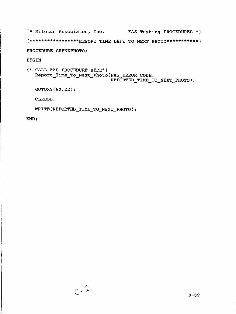
( * Miletus Associates, Inc. FAS Testing PROCEDURES * )
(*****************REPORT TIME LEFT TO NEXT PHOTO***********)
PROCEDURE CHFNXPHOTO;
BEGIN
( * CALL FAS PROCEDURE HERE*) Report Time To Next - Photo(FAS ERROR CODE,
GOTOXY(60,22);
CLREOL;
WRITE(REP0RTED TIME TO NEXT PHOTO);
- - - REP~RTED TIME TO NEXT-PHOTO); - - -
- - - - END ;
c- 2- B-69
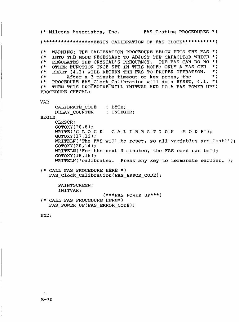
( * Miletus Associates, Inc. FAS Testing PROCEDURES * )
(*****************BEGIN CALIBRATION OF FAS CLOCK***********)
( * WARNING: THE CALIBRATION PROCEDURE BELOW PUTS THE FAS * ) ( * INTO THE MODE NECESSARY TO ADJUST THE CAPACITOR WHICH * ) ( * REGULATES THE CRYSTAL'S FREQUENCY. THE FAS CAN DO NO * ) ( * OTHER FUNCTION ONCE SET IN THIS MODE; ONLY A FAS CPU * ) ( * RESET ( 4 . 3 ) WILL RETURN THE FAS TO PROPER OPERATION. * )
( * PROCEDURE FAS Clock Calibration will do a RESET, 4.1. * )
PROCEDURE CHFCAL;
( * After a 3 minute timeout or key press, the * )
( * THEN THIS PROCEDUREWILL INITVAR AND DO A FAS POWER UP*)
VAR CALIBRATE CODE : BYTE; DELAY - COUNTER : INTEGER;
CLRSCR; GOTOXY(20,8); WRITE('C L 0 C K C A L I B R A T I O N M 0 D E'); GOTOXY(17,12); WRITELN('The FAS will be reset, so all variables are lost!'); GOTOXY(20,14); WRITELN('For the next 3 minutes, the FAS card can be'); GOTOXY ( 18,16 ; WRITELN('ca1ibrated. Press any key to terminate earlier.');
BEGIN
( * CALL FAS PROCEDURE HERE * ) FAS - Clock - Calibration(FAS - ERROR - CODE);
PAINTSCREEN; INITVAR;
(***FAS POWER UP***) ( * CALL FAS PROCEDURE HERE*)
FAS POWER - UP(FAS - ERROR - CODE); END ;
B-70
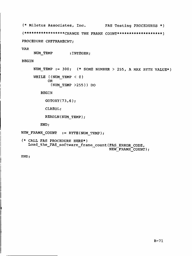
( * Miletus Associates, Inc. FAS Testing PROCEDURES * )
PROCEDURE CHFFRAMECNT;
VAR NUM - TEMP :INTEGER;
BEGIN
NUM - TEMP := 300; ( * SOME NUMBER > 255, A MAX BYTE VALUE*)
WHILE ((NUM - TEMP < 0) OR (NUM - TEMP >255)) DO
BEGIN
CLREOL ;
READLN(NUM TEMP); - END ;
NEW FRAME COUNT
( * CALL FAS PROCEDURE HERE*)
:= BYTE(NUM TEMP); - - -
Load the FAS software frame count(FAS ERROR CODE, - - - - - NEW-FRAME-COUNT); - -
END :
B-71
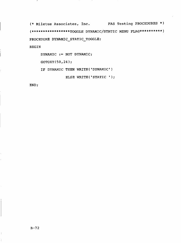
( * Miletus Associates, Inc. FAS Testing PROCEDURES * )
(*****************TOGGLE DYNAMIC/STATIC MENU FLAG**********)
PROCEDURE DYNAMIC - STATIC - TOGGLE:
BEGIN
DYNAMIC := NOT DYNAMIC:
GOTOXY(50,24);
IF DYNAMIC THEN WRITE('DYNAM1C')
ELSE WRITE('STAT1C ' 1;
END :
B-72
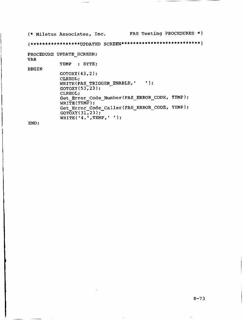
( * Miletus Associates, Inc. FAS Testing PROCEDURES * )
PROCEDURE UPDATE SCREEN; VAR
TEMP : BYTE; BEGIN
GOTOXY(43,2); CLREOL;
-
WRITE(FAS TRIGGER c ENABLE,' I ) ;
GOTOXY(53723); CLREOL; Get Error Code Number(FAS ERROR CODE, TEMP); - - - WRITE (TEMP) ; Get Error Code - Caller(FAS - ERROR - CODE, TEMP); GOTcXY(31723); WRITE('4.',TEMPt' ' 1 ;
END :
B-73
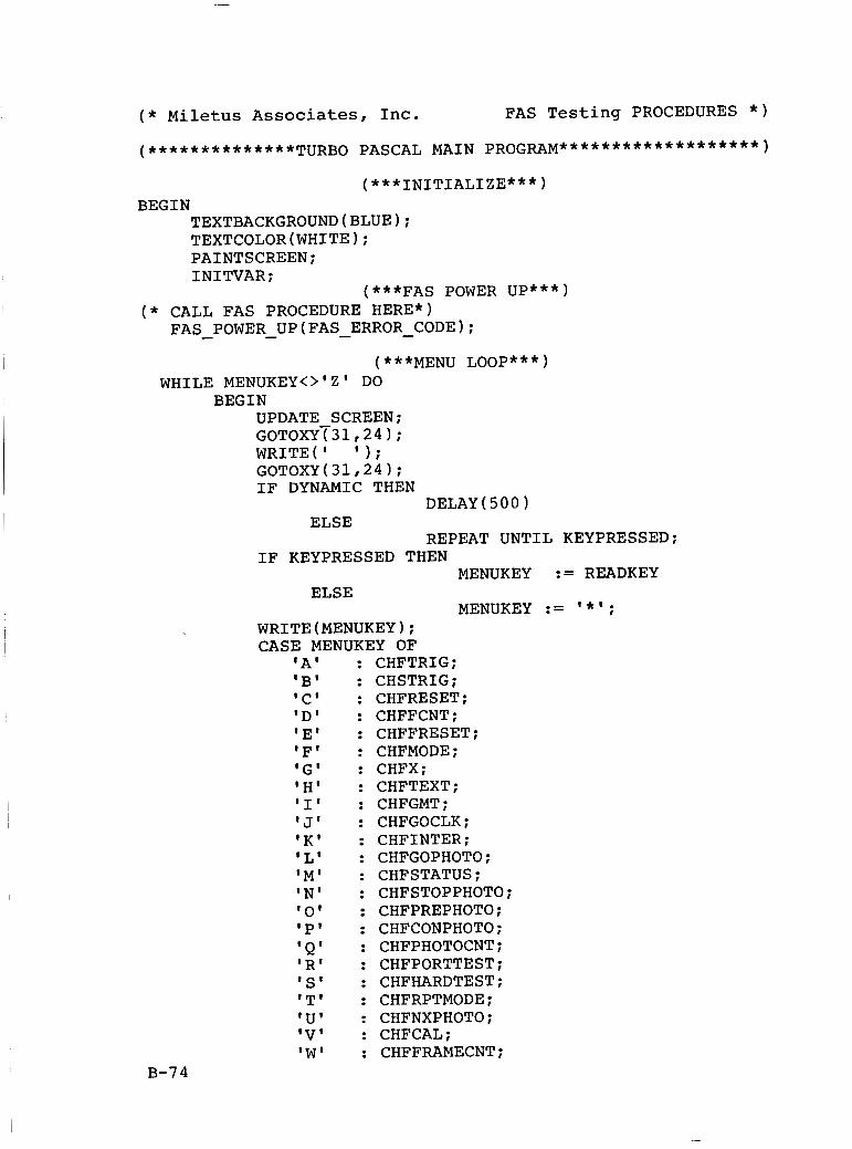
( * Miletus Associates, Inc. FAS Testing PROCEDURES * )
(***INITIALIZE***) BEGIN
TEXTBACKGROUND(BLUE); TEXTCOLOR(WHITE); PAINTSCREEN; INITVAR;
(***FAS POWER UP***) ( * CALL FAS PROCEDURE HERE*)
FAS POWER - UP(FAS - ERROR - CODE); - (***MENU LOOP***)
WHILE MENUKEY<>'Z' DO BEGIN
UPDATE SCREEN; GOTOXYT31,24); WRITE(' ' 1 ; GOTOXY(31,24); IF DYNAMIC THEN
ELSE DELAY(SO0)
REPEAT UNTIL KEYPRESSED; IF KEYPRESSED THEN
MENUKEY := READKEY
MENUKEY := ' * I ;
ELSE
WRITE(MENUKEY1; CASE MENUKEY OF
'A' 'B' 'C' 'D' 'E' IF' 'GI 'H' 'I' ' J' 'K' 'L' 'MI IN' '0' 'P' 'Q' 'R' 'S' 'T' 'U' 'V' 'W'
B-7 4
: CHFTRIG; : CHSTRIG; : CHFRESET; : CHFFCNT; : CHFFRESET; : CHFMODE; : CHFX; : CHFTEXT; : CHFGMT; : CHFGOCLK; : CHFINTER; : CHFGOPHOTO; : CHFSTATUS; : CHFSTOPPHOTO; : CHFPREPHOTO; : CHFCONPHOTO; : CHFPHOTOCNT; : CHFPORTTEST; : CHFHARDTEST; : CHFRPTMODE; : CHFNXPHOTO; : CHFCAL; : CHFFRAMECNT;
( * Miletus Associates, Inc. FAS Testing PROCEDURES * )
'Y' : DYNAMIC - STATIC - TOGGLE: END :
B-7 5
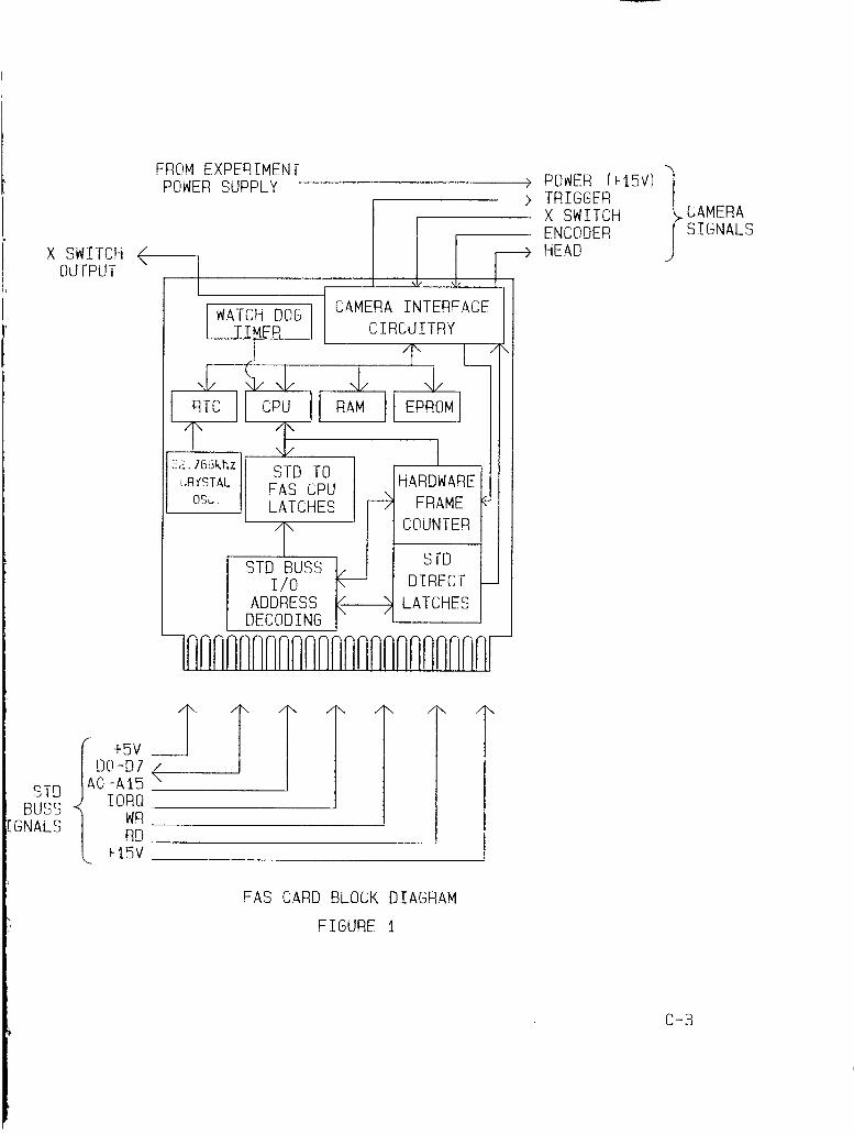
X SWITCH +- OUTPUT
W W I
L
STD BUSS
IGNALS
t 5 v D@-D7
A O - A l 5 I O R Q
WR RD
t 15V
FROM EXPERIMENT POWER SUPPLY >
I I 7
C4MER4 INTERF4CF CIRCUITR r'
t I -
ADDRESS 1-7 LATCHES 1 I I DECODING
I I
' 1 '
. POWER f t15V) 'I TRIGGER X SWITCH ENCODER HEAD .I
FAS CARD BLOCK DIAGRAM
FIGURE 1
c-3
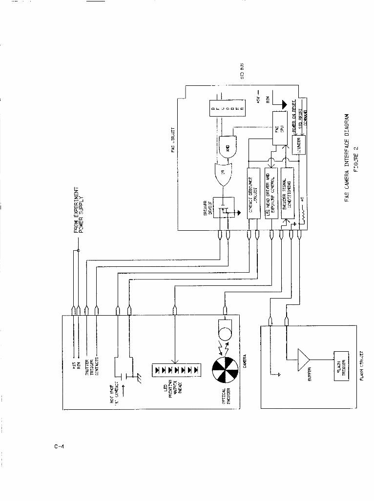
H n
c-4
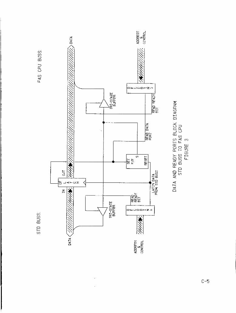
irj IT 3 IC
3 0 n
cn LL a
3 m n t- cn
a-
c3 a a H 0
c n Q m c LL.
a a
n t- 4
c-5
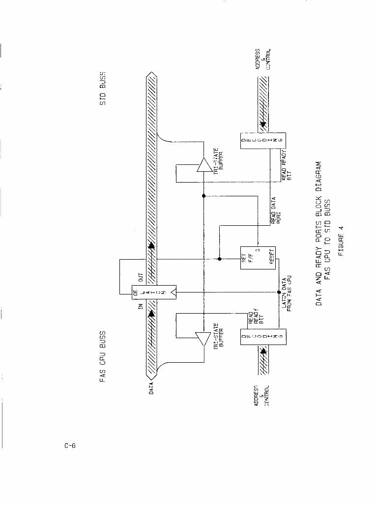
m m 3 m 0 I- m
m CI) 3 m
m a LL.
4 t- 4 CJI
H n
C-6
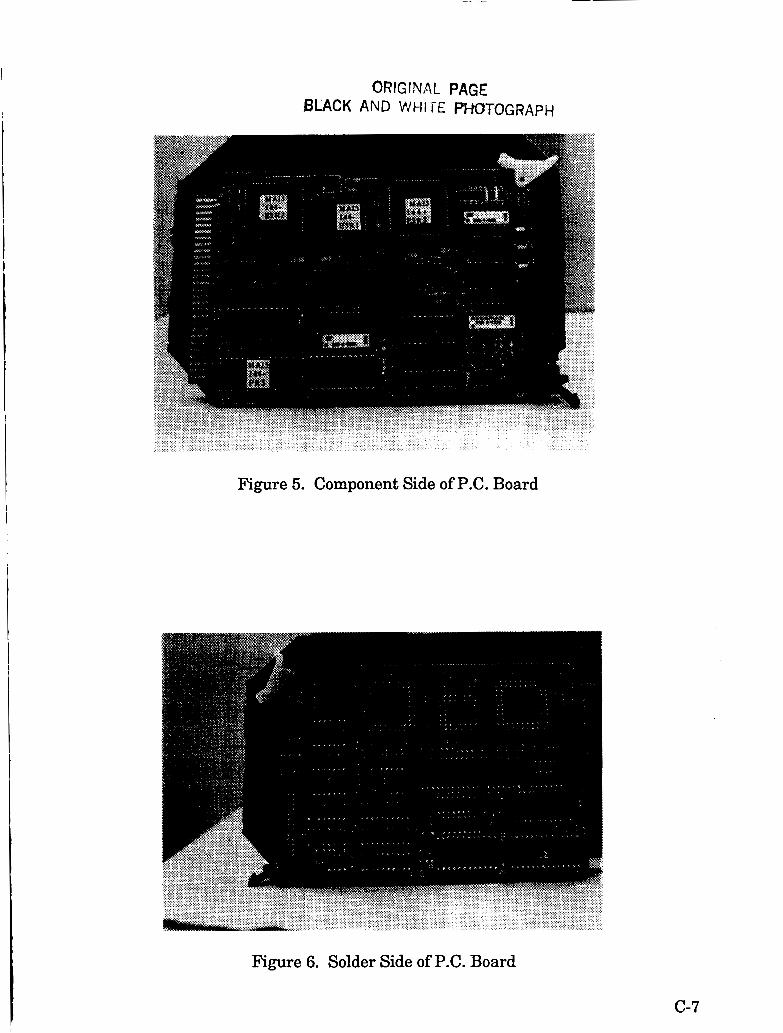
ORIGINAL PAGE BLACK AND WHI TE PHOTOGRAPH
Figure 5. Component Side of P.C. Board
Figure 6. Solder Side of P.C. Board
c-7
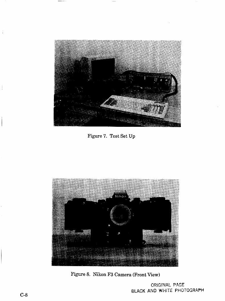
C-8
Figure 7. Test Set Up
Figure 8. Nikon F3 Camera (Front View)
ORIGINAL PAGE BLACK AND WHITE PHOTOGRAPH
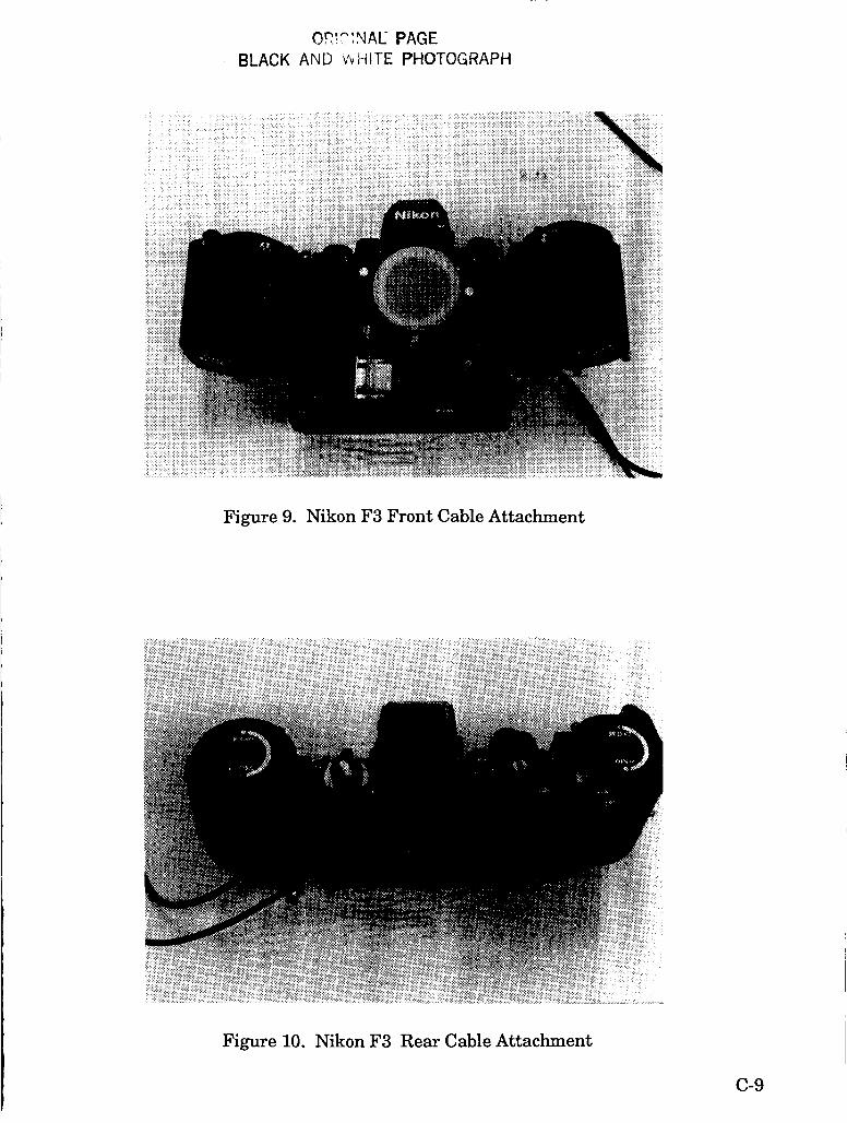
@@!":?IAU PAGE BLACK AND ~ J H I T E PHOTOGRAPH
Figure 9. Nikon F3 Front Cable Attachment
Figure 10. Nikon F3 Rear Cable Attachment
c-9
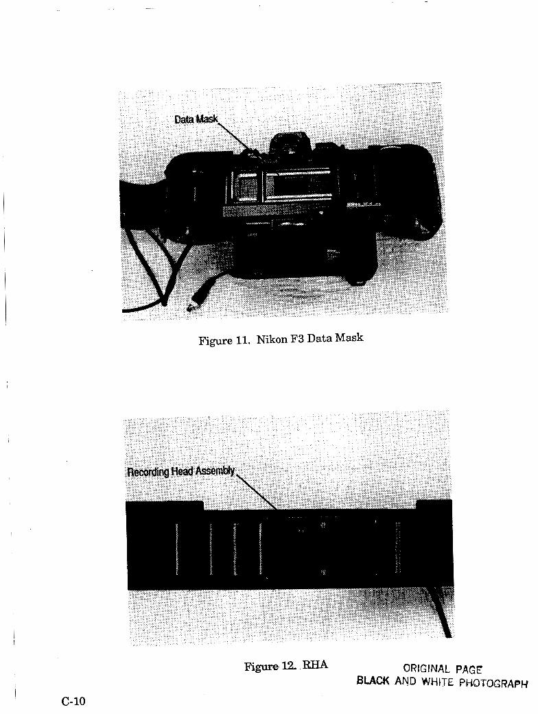
Figure 11. Nikon F3 Data Mask
c-10
ORIGfNAL PAGE BLACK AND WHITE PHOTOGRAPH
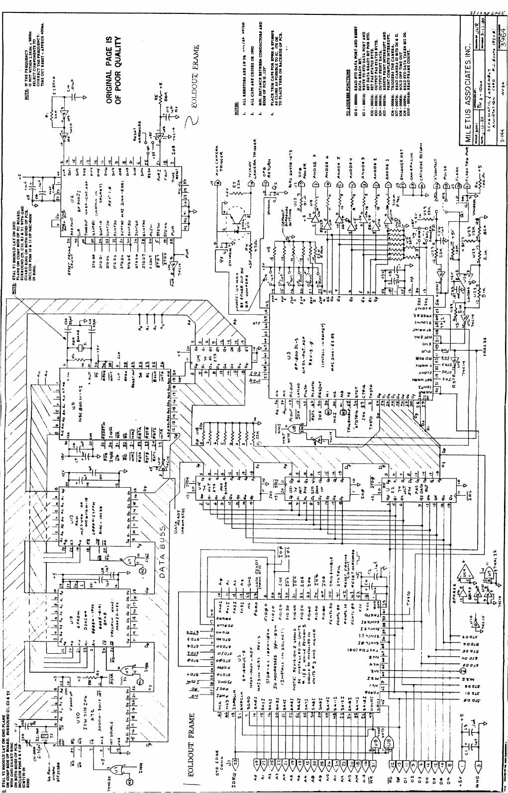
I 1 I t I I I I
Y
w Ir
-;
1
1
2:I E-
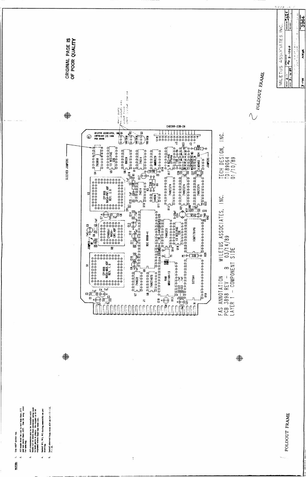
CAb26R-238-39
I -- r /t
.. rn w
0 0
c I
0 i i . . - - 4 .
P
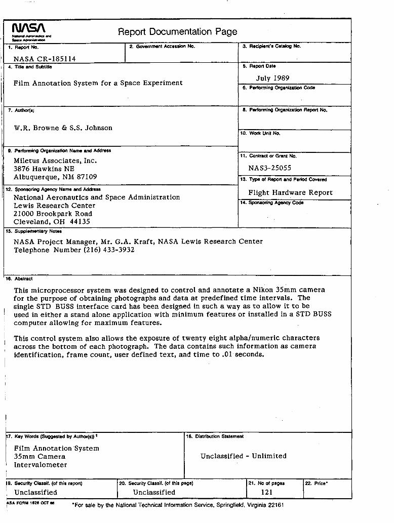
- - M u m CUASA Report Documentation Page 1. Repor(No. 2. Gowmmont Accession No.
NASA CR-185114 4. Title and Subtitle
f o r t h e purpose of obtaining photographs and d a t a at predefined t i m e intervals. The single STD BUSS in te r face card has been designed in such a way as to allow it to b e
Film Annotation System for a Space Experiment
19. Security Classif. (of this r e m )
', Unclassified Unclassified 20. Security Classif. (of thm page)
7. Author(nj
W.R. Browne G S.S. Johnson
21. No of pages
121 22. Price'
0. Performing Organization Name and Address
Miletus Associates,, Inc. 3876 Hawkins NE Albuquerque, NM 87109
12. Sponsoring Agency Name and Address
National Aeronautics and Space Administration Lewis Research Center 21000 Brookpark Road Cleveland, OH 44135
15. Supplementary Notea
3. Rocipient'r Catalog No.
5. Report Date
July 1989 6. Performing Organization C a k
8. Performing Organization Report No.
10. Work Unit NO.
11. Contract or Grant NO.
NAS3-25055 13. Type of Report and Period Covered
Flight Hardware Report 14. Sponsoring Agency W e
NASA Project Manager, Mr. G.A. Kraft , NASA Lewis Research Center Telephone Number (216) 433-3932
-..- 16. Abstract
t !
This control system also allows t h e exposure of twenty eight a l p h a h u m e r i c charac te rs across t h e bot tom of each photograph. The d a t a contains such information as c a m e r a identification, f r a m e count, user defined text , and t i m e to .01 seconds.
I
17. Key Words (Suggested by Autwsj) * 118. Distribution Statement
Film Annotation 'System 35mm C a m e r a Intervalometer
Unclassified - Unlimited