fieldserver modbus to bacnet start-up guide fs … network_and_wireless/pdfs/ez...driver version:...
TRANSCRIPT
Driver Version: 6.15
Document Revision: 6
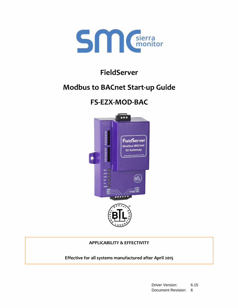
FieldServer
Modbus to BACnet Start-up Guide
FS-EZX-MOD-BAC
APPLICABILITY & EFFECTIVITY
Effective for all systems manufactured after April 2015

Modbus to BACnet Start-up Guide
Contact Information
Contact Information:
Thank you for purchasing the FieldServer.
Please call us for Technical support of the FieldServer product.
Contact Information:
Sierra Monitor Corporation
1991 Tarob Court
Milpitas, CA 95035
Contact number:
+1 408 262-6611
+1 800 727-4377
Email: [email protected]
Website: www.sierramonitor.com

Modbus to BACnet Start-up Guide
Table of Contents
TABLE OF CONTENTS
1 Equipment Set-up ...................................................................................................................................................... 5
2 Certification ................................................................................................................................................................. 5
2.1 BTL Mark – BACnet Testing Laboratory .................................................................................................................. 5
3 Supplied equipment ................................................................................................................................................... 5
4 Mounting ...................................................................................................................................................................... 6
4.1 Dimensions ................................................................................................................................................................... 6
4.1.1 Dimension Drawing FS-EZX-MOD-BAC .......................................................................................................... 6
4.2 Specifications ............................................................................................................................................................... 7
5 Installing the EZ Gateway ......................................................................................................................................... 8
5.1 RS-485 .......................................................................................................................................................................... 8
5.1.1 RS-485 Connection R2 port ............................................................................................................................... 8
5.1.2 RS-485 Connection R1 Port............................................................................................................................... 8
6 Operation ..................................................................................................................................................................... 9
6.1 Power up the device .................................................................................................................................................... 9
6.2 Connect the PC to the EZ Gateway over the Ethernet port. ................................................................................. 9
6.3 Connecting to the EZ Gateway ................................................................................................................................ 10
6.3.1 Using the Toolbox application to discover and connect to the EZ Gateway: ............................................ 10
6.3.2 Using a Web Browser directly .......................................................................................................................... 11
6.4 Set IP Address of the EZ Gateway ......................................................................................................................... 11
6.4.1 Using the Toolbox Application to set the IP address: ................................................................................... 11
7 Configuring the EZ Gateway .................................................................................................................................. 14
7.1 Setting up the Connections ...................................................................................................................................... 14
7.2 Creating Device Profiles ........................................................................................................................................... 15
7.3 Importing a Device Profile ........................................................................................................................................ 19
7.4 Adding Device Profiles .............................................................................................................................................. 20
7.5 Test and Commission the EZ Gateway .................................................................................................................. 21
Appendix A Troubleshooting Tips ................................................................................................................................ 22
Appendix A.1. Communicating with the EZ Gateway over the Network ....................................................................... 22
Appendix A.2. Technical support ........................................................................................................................................ 22
Appendix A.3. Notes Regarding Subnets and Subnet Masks ........................................................................................ 22
Appendix B Reference .................................................................................................................................................... 23
Appendix B.1. LED Functions .............................................................................................................................................. 23
Appendix B.2. Compliance with UL Regulations .............................................................................................................. 24
Appendix C Limited 2 year Warranty ........................................................................................................................... 25
Modbus to BACnet Start-up Guide
Table of Contents
LIST OF FIGURES
Figure 1 – EZ Gateway Dimension Drawing ........................................................................................................................... 6
Figure 2 – R2 Port connection ................................................................................................................................................... 8
Figure 3 – R1 Port connection ................................................................................................................................................... 8
Figure 4 – Power Connection .................................................................................................................................................... 9
Figure 5 – Ethernet Port ............................................................................................................................................................. 9
Figure 6 – Main page ................................................................................................................................................................ 11
Figure 7 – The Connections page ........................................................................................................................................... 14
Figure 8 – Creating Device Profiles ........................................................................................................................................ 15
Figure 9 – Creating Device Profiles ........................................................................................................................................ 15
Figure 10 – Mapping BACnet addresses to the Modbus Registers ................................................................................... 16
Figure 11 – Mapping BACnet addresses to the Modbus Registers ................................................................................... 16
Figure 12 – Define the State Table & variables .................................................................................................................... 17
Figure 13 – Defining Parameters of Notification Class ........................................................................................................ 17
Figure 14 – Define Profiles....................................................................................................................................................... 18
Figure 15 – Export Profile......................................................................................................................................................... 18
Figure 16 – Importing Device Profile ...................................................................................................................................... 19
Figure 17 – Choose Profile to Load ........................................................................................................................................ 20
Figure 18 – Adding device profiles.......................................................................................................................................... 20
Figure 19 - Connections screen .............................................................................................................................................. 21
Figure 20 – LED allocation ....................................................................................................................................................... 23
Modbus to BACnet Start-up Guide
Page 5 of 25
1 EQUIPMENT SET-UP1
EZ Gateway is a high performance, cost effective Building and Industrial Automation multi-protocol
gateway providing protocol translation between serial and Ethernet, devices and networks.
2 CERTIFICATION
2.1 BTL Mark – BACnet Testing Laboratory
The BTL Mark on EZ Gateway is a symbol that indicates that a product has passed
a series of rigorous tests conducted by an independent laboratory which verifies that
the product correctly implements the BACnet features claimed in the listing. The
mark is a symbol of a high-quality BACnet product.
Go to http://www.BACnetInternational.net/btl/ for more information about the BACnet
Testing Laboratory. Click here for BACnet PIC Statement.
3 SUPPLIED EQUIPMENT
EZ Gateway.
Preloaded with the Modbus and BACnet drivers.
All instruction manuals, driver manuals, configuration manuals and support utilities are available on
the USB drive provided in the optional accessory kit, or on-line at
http://www.sierramonitor.com/customer-care/resource-center?filters=software-downloads
Accessory kit (Optional) (Part # FS-8915-36-QS) including:
7-ft CAT5 cable with RJ45 connectors at both ends
Power Supply -110/220V (p/n 69196)
DIN Rail mounting bracket
Screwdriver for connecting to terminals
USB Flash drive loaded with:
o Modbus to BACnet Start-up Guide
o FieldServer Configuration Manual
o FieldServer Utilities Manual
o All FieldServer Driver Manuals
o Support Utilities
o Any additional folders related to special files configured for a specific EZ Gateway
o Additional components as required - See Driver Manual Supplement for details
1 BACnet is a registered trademark of ASHRAE
Modbus to BACnet Start-up Guide
Page 6 of 25
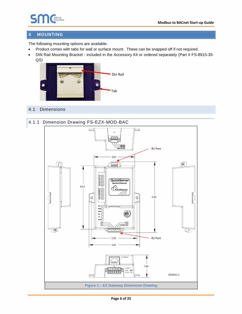
4 MOUNTING
The following mounting options are available:
Product comes with tabs for wall or surface mount. These can be snapped off if not required.
DIN Rail Mounting Bracket - included in the Accessory Kit or ordered separately (Part # FS-8915-35-
QS)
4.1 Dimensions
4.1.1 Dimension Drawing FS-EZX-MOD-BAC
R1 Port
R2 Port
Tab
Din Rail
Figure 1 – EZ Gateway Dimension Drawing

Modbus to BACnet Start-up Guide
Page 7 of 25
4.2 Specifications2
FS-EZX-MOD-BAC
Available Ports
One 6-pin Phoenix connector with:
RS-485 port (+ / - / gnd)
Power port (+ / - / Frame-gnd)
One 3-pin Phoenix connector with:
RS-485 port (+ / - / gnd)
One Ethernet 10/100 BaseT port
Power Requirements
Input Voltage: 9-30VDC or 12-24VAC
Input Power Frequency 50/60 Hz.
Power Rating: 2.5 Watts
Current draw @ 12V, 150 mA
Approvals
TUV approved to UL 916 Standard
RoHS Compliant
FCC Part 15 Compliant
CE Mark
BTL Mark
Surge Suppression
EN61000-4-2 ESD EN61000-4-3 EMC EN61000-4-4 EFT
Physical Dimensions(excluding the external power supply)
(WxDxH): 5.05 x 2.91 x 1.6 in. (12.82 x 7.39 x 4.06 cm) excluding mounting tabs
Weight: 0.4 lbs (0.2 Kg)
Environment:
Operating Temperature: -40°C to 75°C (-40°F to167°F)
Humidity: 5 - 90% RH (non-condensing)
“This device complies with part 15 of the FCC Rules. Operation is subject to the following two conditions:
This device may not cause harmful interference
This device must accept any interference received, including interference that may cause
undesired operation.
Note: This equipment has been tested and found to comply with the limits for a Class A digital device,
pursuant to part 15 of the FCC Rules. These limits are designed to provide reasonable protection against
harmful interference when the equipment is operated in a commercial environment. This equipment
generates, uses, and can radiate radio frequency energy and, if not installed and used in accordance with
the instruction manual, may cause harmful interference to radio communications. Operation of this
equipment in a residential area is likely to cause harmful interference in which case the user will be
required to correct the interference at his expense.
Modifications not expressly approved by Sierra Monitor could void the user's authority to operate the
equipment under FCC rules” 2 Specifications subject to change without notice
Modbus to BACnet Start-up Guide
Page 8 of 25
5 INSTALLING THE EZ GATEWAY
5.1 RS-485
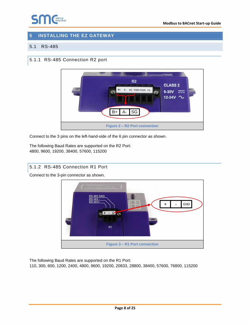
5.1.1 RS-485 Connection R2 port
Connect to the 3 pins on the left-hand-side of the 6 pin connector as shown.
The following Baud Rates are supported on the R2 Port:
4800, 9600, 19200, 38400, 57600, 115200
5.1.2 RS-485 Connection R1 Port
Connect to the 3-pin connector as shown.
The following Baud Rates are supported on the R1 Port:
110, 300, 600, 1200, 2400, 4800, 9600, 19200, 20833, 28800, 38400, 57600, 76800, 115200
+ - GND
B+ A- SG
Figure 2 – R2 Port connection
Figure 3 – R1 Port connection
Modbus to BACnet Start-up Guide
Page 9 of 25
6 OPERATION
6.1 Power up the device
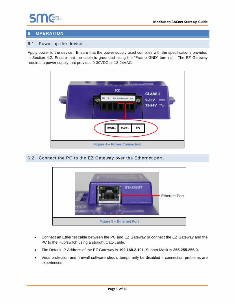
Apply power to the device. Ensure that the power supply used complies with the specifications provided
in Section 4.2. Ensure that the cable is grounded using the “Frame GND” terminal. The EZ Gateway
requires a power supply that provides 9-30VDC or 12-24VAC.
6.2 Connect the PC to the EZ Gateway over the Ethernet port.
Connect an Ethernet cable between the PC and EZ Gateway or connect the EZ Gateway and the
PC to the Hub/switch using a straight Cat5 cable.
The Default IP Address of the EZ Gateway is 192.168.2.101, Subnet Mask is 255.255.255.0.
Virus protection and firewall software should temporarily be disabled if connection problems are
experienced .
Ethernet Port
PWR+ PWR- FG
Figure 4 – Power Connection
Figure 5 – Ethernet Port
Modbus to BACnet Start-up Guide
Page 10 of 25
6.3 Connecting to the EZ Gateway
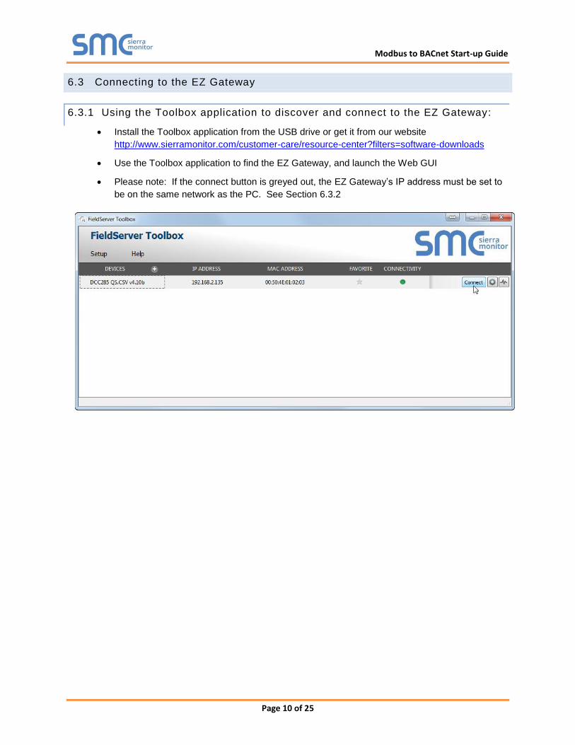
6.3.1 Using the Toolbox application to discover and connect to the EZ Gateway:
Install the Toolbox application from the USB drive or get it from our website
http://www.sierramonitor.com/customer-care/resource-center?filters=software-downloads
Use the Toolbox application to find the EZ Gateway, and launch the Web GUI
Please note: If the connect button is greyed out, the EZ Gateway’s IP address must be set to
be on the same network as the PC. See Section 6.3.2
Modbus to BACnet Start-up Guide
Page 11 of 25
6.3.2 Using a Web Browser directly
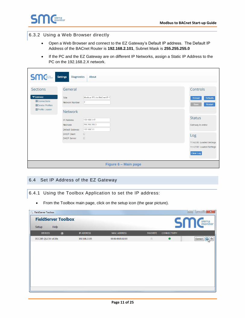
Open a Web Browser and connect to the EZ Gateway’s Default IP address. The Default IP
Address of the BACnet Router is 192.168.2.101, Subnet Mask is 255.255.255.0
If the PC and the EZ Gateway are on different IP Networks, assign a Static IP Address to the
PC on the 192.168.2.X network.
6.4 Set IP Address of the EZ Gateway
6.4.1 Using the Toolbox Application to set the IP address:
From the Toolbox main page, click on the setup icon (the gear picture).
Figure 6 – Main page
Modbus to BACnet Start-up Guide
Page 12 of 25
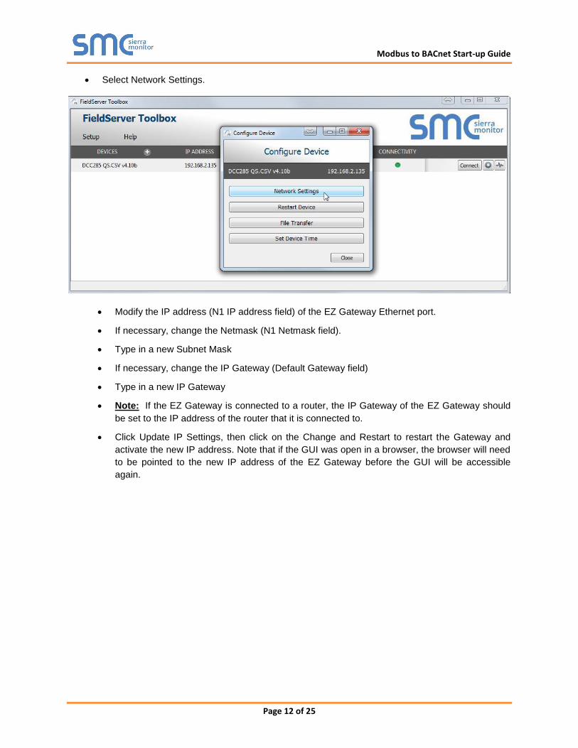
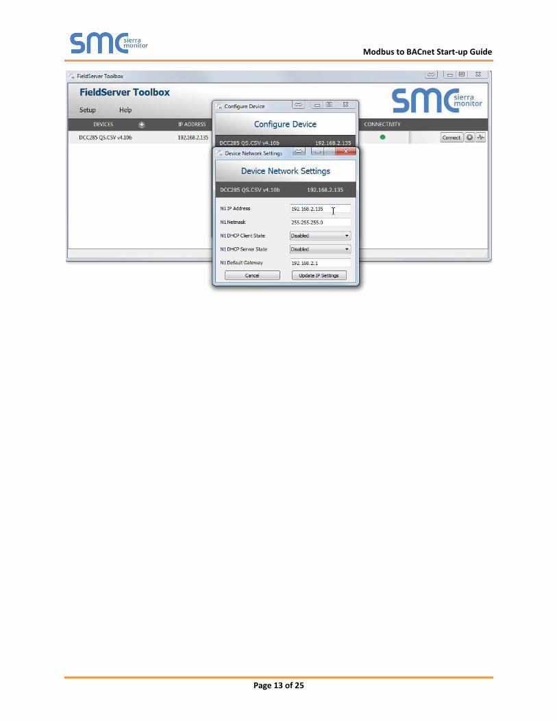
Select Network Settings.
Modify the IP address (N1 IP address field) of the EZ Gateway Ethernet port.
If necessary, change the Netmask (N1 Netmask field).
Type in a new Subnet Mask
If necessary, change the IP Gateway (Default Gateway field)
Type in a new IP Gateway
Note: If the EZ Gateway is connected to a router, the IP Gateway of the EZ Gateway should
be set to the IP address of the router that it is connected to.
Click Update IP Settings, then click on the Change and Restart to restart the Gateway and
activate the new IP address. Note that if the GUI was open in a browser, the browser will need
to be pointed to the new IP address of the EZ Gateway before the GUI will be accessible
again.
Modbus to BACnet Start-up Guide
Page 13 of 25
Modbus to BACnet Start-up Guide
Page 14 of 25
7 CONFIGURING THE EZ GATEWAY
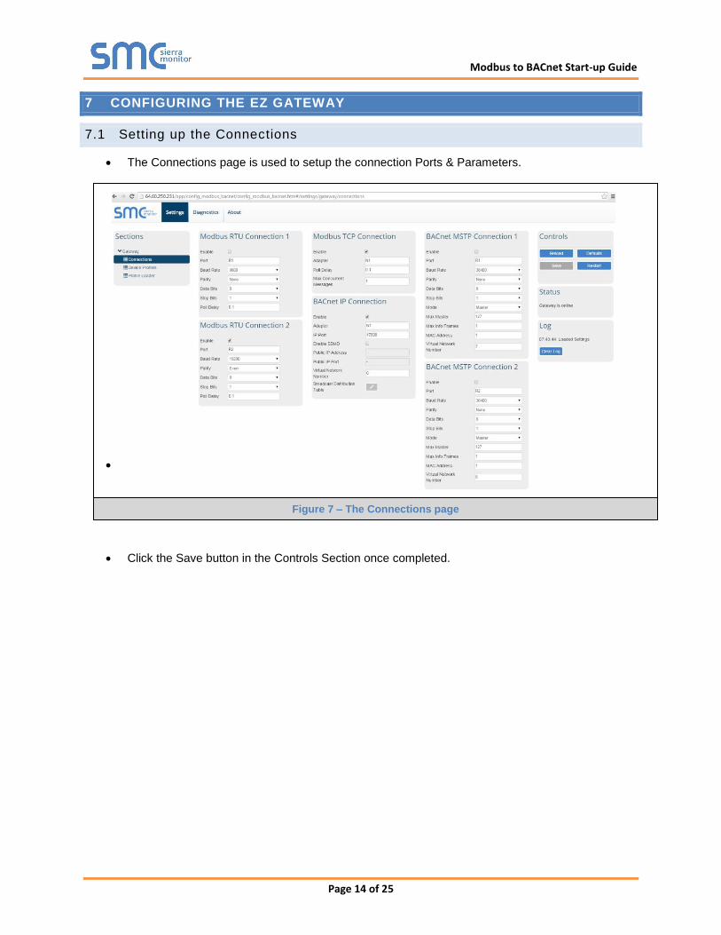
7.1 Setting up the Connections
The Connections page is used to setup the connection Ports & Parameters.
Click the Save button in the Controls Section once completed.
Figure 7 – The Connections page
Modbus to BACnet Start-up Guide
Page 15 of 25
7.2 Creating Device Profiles
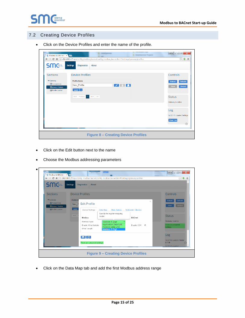
Click on the Device Profiles and enter the name of the profile.
Click on the Edit button next to the name
Choose the Modbus addressing parameters
Click on the Data Map tab and add the first Modbus address range
Figure 8 – Creating Device Profiles
Figure 9 – Creating Device Profiles
Modbus to BACnet Start-up Guide
Page 16 of 25
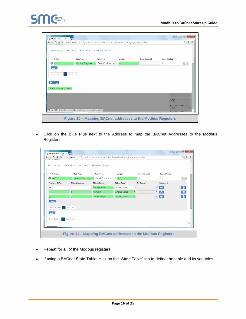
Click on the Blue Plus next to the Address to map the BACnet Addresses to the Modbus
Registers.
Repeat for all of the Modbus registers
If using a BACnet State Table, click on the “State Table” tab to define the table and its variables.
Figure 10 – Mapping BACnet addresses to the Modbus Registers
Figure 11 – Mapping BACnet addresses to the Modbus Registers
Modbus to BACnet Start-up Guide
Page 17 of 25
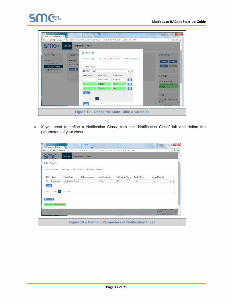
If you need to define a Notification Class, click the “Notification Class” tab and define the
parameters of your class.
Figure 12 – Define the State Table & variables
Figure 13 – Defining Parameters of Notification Class
Modbus to BACnet Start-up Guide
Page 18 of 25
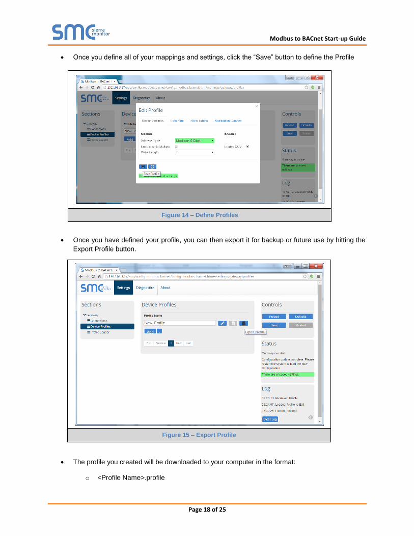
Once you define all of your mappings and settings, click the “Save” button to define the Profile
Once you have defined your profile, you can then export it for backup or future use by hitting the
Export Profile button.
The profile you created will be downloaded to your computer in the format:
o <Profile Name>.profile
Figure 14 – Define Profiles
Figure 15 – Export Profile
Modbus to BACnet Start-up Guide
Page 19 of 25
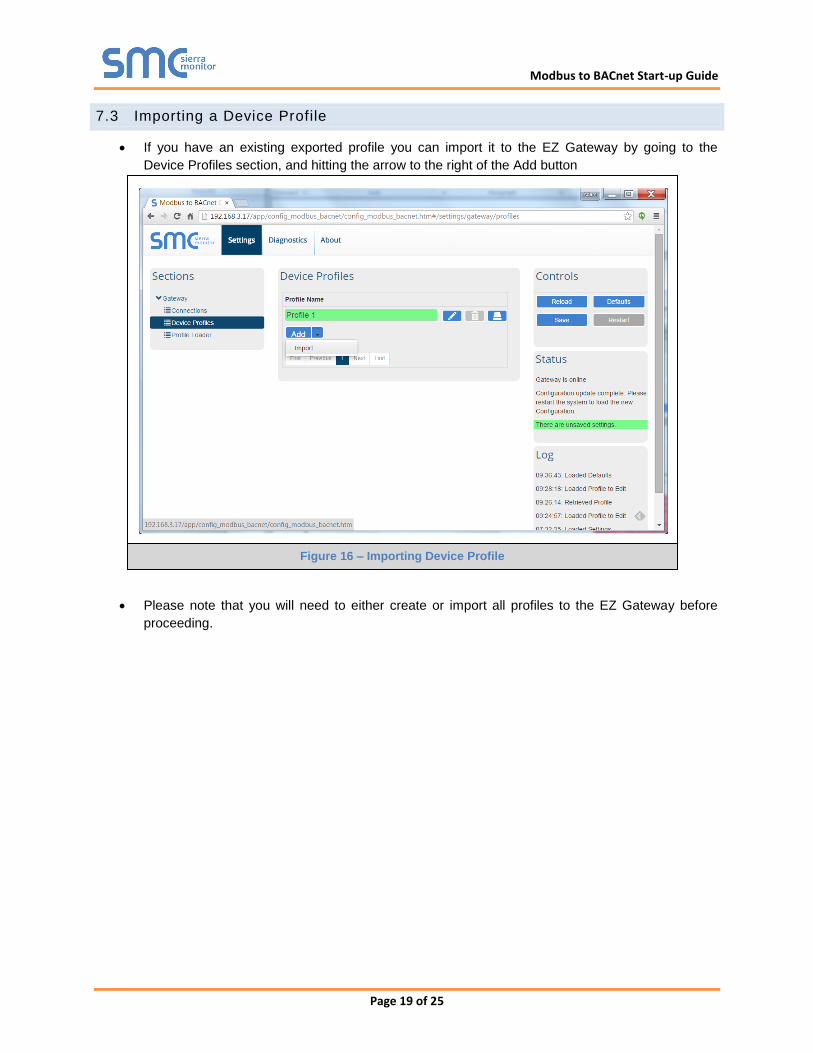
7.3 Importing a Device Profile
If you have an existing exported profile you can import it to the EZ Gateway by going to the
Device Profiles section, and hitting the arrow to the right of the Add button
Please note that you will need to either create or import all profiles to the EZ Gateway before
proceeding.
Figure 16 – Importing Device Profile
Modbus to BACnet Start-up Guide
Page 20 of 25
7.4 Adding Device Profiles
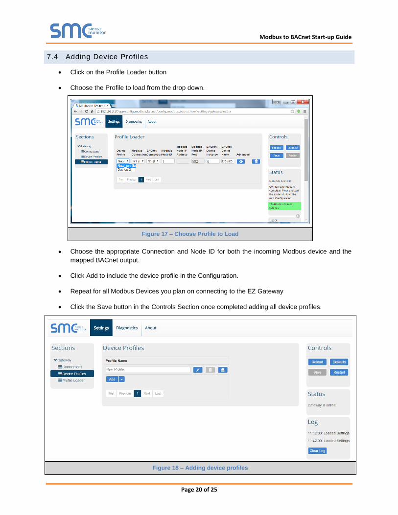
Click on the Profile Loader button
Choose the Profile to load from the drop down.
Choose the appropriate Connection and Node ID for both the incoming Modbus device and the
mapped BACnet output.
Click Add to include the device profile in the Configuration.
Repeat for all Modbus Devices you plan on connecting to the EZ Gateway
Click the Save button in the Controls Section once completed adding all device profiles.
Figure 18 – Adding device profiles
Figure 17 – Choose Profile to Load
Modbus to BACnet Start-up Guide
Page 21 of 25
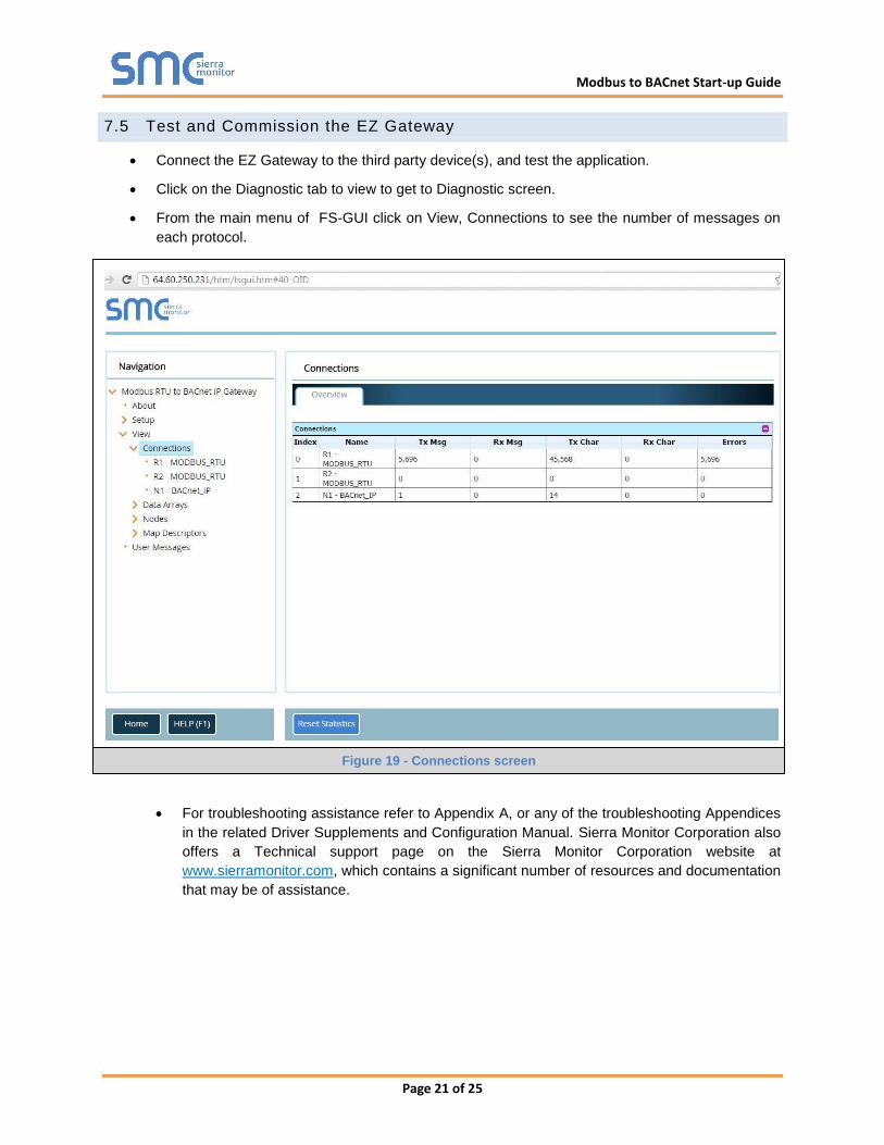
7.5 Test and Commission the EZ Gateway
Connect the EZ Gateway to the third party device(s), and test the application.
Click on the Diagnostic tab to view to get to Diagnostic screen.
From the main menu of FS-GUI click on View, Connections to see the number of messages on
each protocol.
For troubleshooting assistance refer to Appendix A, or any of the troubleshooting Appendices
in the related Driver Supplements and Configuration Manual. Sierra Monitor Corporation also
offers a Technical support page on the Sierra Monitor Corporation website at
www.sierramonitor.com, which contains a significant number of resources and documentation
that may be of assistance.
Figure 19 - Connections screen

Modbus to BACnet Start-up Guide
Page 22 of 25
Appendix A Troubleshooting Tips
Appendix A.1. Communicating with the EZ Gateway over the Network
Confirm that the network cabling is correct.
Confirm that the computer network card is operational and correctly configured.
Confirm that there is an Ethernet adapter installed in the PC’s Device Manager List, and that it is
configured to run the TCP/IP protocol.
Check that the IP netmask of the PC matches the EZ Gateway. The Default IP Address of the EZ
Gateway is 192.168.2.X, Subnet Mask is 255.255.255.0.
o Go to Start|Run
o Type in “ipconfig”
o The account settings should be displayed.
o Ensure that the IP address is 102.168.2.X and the netmask 255.255.255.0
Ensure that the PC and EZ Gateway are on the same IP Network, or assign a Static IP Address to
the PC on the 192.168.2.0 network.
If using Windows XP or later, ensure that the firewall is disabled.
Ensure that all other Ethernet cards active on the PC, especially wireless adapters are disabled.
Refer to the FieldServer Troubleshooting Guide which can be found at
http://www.sierramonitor.com/customer-care/resource-center?filters=software-downloads for further
information.
Appendix A.2. Technical support
Before contacting Technical support to report an issue, take a diagnostic capture by using the FieldServer
Toolbox and click on the Diagnose button to take a diagnostic capture. Send this log together with a
detailed description of the problem to [email protected] for evaluation
Note that while all necessary documentation is shipped with the FieldServer on the USB flash drive, these
documents are constantly being updated. Newer versions may be available on the web at
http://www.sierramonitor.com/customer-care/resource-center?filters=software-downloads/
Appendix A.3. Notes Regarding Subnets and Subnet Masks
Please Note that RFC standards allocate the IP address range of 192.0.0.0 through to 223.255.255.255
to be used in Class-C subnetting (i.e.: Subnets listed as 255.255.255.xxx, where xxx can vary based on
filtering required).
Consequently, the IP stack for this product will not allow any IP addresses in this range to be allocated a
subnet that does not fall within the Class C range.
Modbus to BACnet Start-up Guide
Page 23 of 25
Appendix B Reference
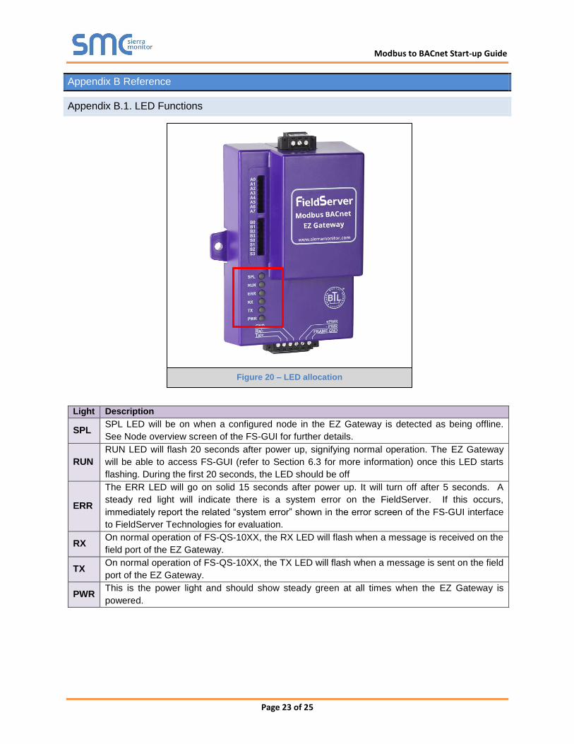
Appendix B.1. LED Functions
Light Description
SPL SPL LED will be on when a configured node in the EZ Gateway is detected as being offline.
See Node overview screen of the FS-GUI for further details.
RUN
RUN LED will flash 20 seconds after power up, signifying normal operation. The EZ Gateway
will be able to access FS-GUI (refer to Section 6.3 for more information) once this LED starts
flashing. During the first 20 seconds, the LED should be off
ERR
The ERR LED will go on solid 15 seconds after power up. It will turn off after 5 seconds. A
steady red light will indicate there is a system error on the FieldServer. If this occurs,
immediately report the related “system error” shown in the error screen of the FS-GUI interface
to FieldServer Technologies for evaluation.
RX On normal operation of FS-QS-10XX, the RX LED will flash when a message is received on the
field port of the EZ Gateway.
TX On normal operation of FS-QS-10XX, the TX LED will flash when a message is sent on the field
port of the EZ Gateway.
PWR This is the power light and should show steady green at all times when the EZ Gateway is
powered.
Figure 20 – LED allocation
Modbus to BACnet Start-up Guide
Page 24 of 25
Appendix B.2. Compliance with UL Regulations
For UL compliance, the following instructions must be met when operating the EZ Gateway.
The units shall be powered by listed LPS or Class 2 power supply suited to the expected
operating temperature range.
The interconnecting power connector and power cable shall:
Comply with local electrical code.
Be suited to the expected operating temperature range.
Meet the current and voltage rating for the EZ Gateway/Net
Furthermore, the interconnecting power cable shall:
Be of length not exceeding 3.05m (118.3”)
Be constructed of materials rated VW-1 or FT-1 or better.
If the unit is to be installed in an operating environment with a temperature above 65 °C, it should
be installed in a Restricted Access Area requiring a key or a special tool to gain access
This device must not be connected to a LAN segment with outdoor wiring.

Modbus to BACnet Start-up Guide
Page 25 of 25
Appendix C Limited 2 year Warranty
Sierra Monitor Corporation warrants its products to be free from defects in workmanship or material under
normal use and service for two years after date of shipment. Sierra Monitor Corporation will repair or
replace any equipment found to be defective during the warranty period. Final determination of the
nature and responsibility for defective or damaged equipment will be made by Sierra Monitor Corporation
personnel.
All warranties hereunder are contingent upon proper use in the application for which the product was
intended and do not cover products which have been modified or repaired without Sierra Monitor
Corporation’s approval or which have been subjected to accident, improper maintenance, installation or
application, or on which original identification marks have been removed or altered. This Limited
Warranty also will not apply to interconnecting cables or wires, consumables or to any damage resulting
from battery leakage.
In all cases Sierra Monitor Corporation’s responsibility and liability under this warranty shall be limited to
the cost of the equipment. The purchaser must obtain shipping instructions for the prepaid return of any
item under this warranty provision and compliance with such instruction shall be a condition of this
warranty.
Except for the express warranty stated above, Sierra Monitor Corporation disclaims all warranties with
regard to the products sold hereunder including all implied warranties of merchantability and fitness and
the express warranties stated herein are in lieu of all obligations or liabilities on the part of Sierra Monitor
Corporation for damages including, but not limited to, consequential damages arising out of/or in
connection with the use or performance of the product.