field-testing procedure optical fibre cabling sub-system€¦ · either lspm or otdr can be used to...
TRANSCRIPT

Cabling Solutions
Field-testing procedure
Optical fibre cabling sub-system
NCS / February 2020 – Revision 5.05

February 2020 Doc. N°: Of field testing procedure 5_05.docx
Nexans Cabling Solutions 2020 Page 2/70
Table of contents
1. INTRODUCTION ........................................................................................ 4
1.1. International Standards for fibre testing in customer premises ........................... 4
1.2. Latest evolution of the Standards ........................................................................ 4
1.3. Summary of the updated NCS testing procedure................................................ 4
1.4. NCS rules and recommendations about testing equipment ................................ 5
1.5. Additional information .......................................................................................... 6
2. SYSTEM WARRANTY ............................................................................... 7
2.1. The NCS Certified System Warranty ................................................................... 7
2.2. Warranty certification ........................................................................................... 8
2.3. Certified tester overview ...................................................................................... 9
2.3.1. Fluke Network ...................................................................................................... 9
2.3.2. Softing ............................................................................................................... 11
2.3.3. Ideal Industries .................................................................................................. 13
2.3.4. EXFO ................................................................................................................. 15
2.3.5. VIAVI / JDSU ..................................................................................................... 17
3. LSPM TESTING - GENERAL INFORMATION ......................................... 20
3.1. Attenuation (Insertion Loss) parameter ............................................................. 20
3.2. Acceptable link loss calculation ......................................................................... 20
3.3. Common limits ................................................................................................... 21
3.4. Connector loss limits according to ISO 14763-3:2006 ...................................... 21
3.5. Insertion Loss of MTP/LC modules ................................................................... 22
3.6. Polarity maintenance ......................................................................................... 22
3.6.1. Duplex channel polarity maintenance ............................................................... 22
3.6.2. MPO/MTP polarity maintenance ....................................................................... 23
3.7. LSPM Field-testing equipment set-up and care ................................................ 23
3.8. Insertion Loss testing methodologies ................................................................ 24
3.8.1. The “One-Cord” Reference method (RTM) ....................................................... 24
3.8.2. “Two-Cord” Reference method / Setup 2 from ISO 61280-4-1 (ATM) .............. 24
3.8.3. “Three-Cord” Reference method (not supported) .............................................. 24
3.9. Materials needed ............................................................................................... 25
3.10. Test tool configuration ....................................................................................... 26
4. LSPM TESTING PROCEDURES.............................................................. 27
4.1. “One-Cord” Reference method - Single fibre measurement ............................. 28
4.2. “One-Cord” Reference method - Dual fibre measurement ................................ 31
4.3. LSPM testing of MTP links terminated with MTP/LC cassettes ........................ 34
4.4. LSPM testing of MTP trunks .............................................................................. 35
4.4.1. MTP PRO test cords.......................................................................................... 36
4.4.2. “One-cord” Reference method using standard (LC) OF tester .......................... 36
4.4.3. “One-cord” Reference method using MPO tester ............................................. 40

February 2020 Doc. N°: Of field testing procedure 5_05.docx
Nexans Cabling Solutions 2020 Page 3/70
5. OTDR TESTING - GENERAL INFORMATION ......................................... 42
5.1. Attenuation (Insertion Loss) parameter ............................................................. 42
5.2. Field-testing equipment set-up and care ........................................................... 42
6. OTDR TESTING PROCEDURES ............................................................. 44
6.1. Direction of measurement ................................................................................. 45
6.2. Materials needed ............................................................................................... 46
6.3. Test tool configuration ....................................................................................... 47
6.4. Testing ............................................................................................................... 48
7. TROUBLESHOOTING .............................................................................. 51
8. ANNEXES ................................................................................................ 52
8.1. Normative references ........................................................................................ 52
8.2. OF Complementary Warranty Application Data Form ....................................... 53
8.3. OTDR trace analysis and link loss calculations ................................................. 58
8.4. Fibre Optic cabling compliance testing requirements ....................................... 68
8.5. Acceptable link loss calculation with ISO 14763-3 ............................................ 68
8.6. Index of Refraction of NCS LANmark-OF fibres ................................................ 70

February 2020 Doc. N°: Of field testing procedure 5_05.docx
Nexans Cabling Solutions 2020 Page 4/70
1. Introduction
1.1. International Standards for fibre testing in customer premises
This document specifies the procedure for field-testing the transmission performance of Nexans Cabling solutions (NCS) installed optical fibres links in premises.
The ISO/IEC 14763 Standard specifies the implementation and operation of customer premises cabling.
ISO/IEC 14763-3 is derived from IEC 61280-4-1 & IEC 61280-4-2 and adapted specifically in support of ISO/IEC 11801.
Part 3 of this ISO document (14763-3) details test procedures for optical fibre cabling designed in accordance with ISO/IEC 11801 edition 3: 2017/Cor 1:2018 and installed in accordance with the recommendations of ISO/IEC 14763-2 (planning and installation of customer premises cabling).
IEC 61280-4-5 (draft – under study) is dedicated to the attenuation measurement of MPO terminated links using test equipment with MPO interfaces.
1.2. Latest evolution of the Standards
Amendment 1 to the ISO/IEC 14763-3 edition 2:2014 was published in 2018.
ISO/IEC 61280-4-1 ed. 2.0 (multimode fibres) was updated in 2009. The edition 3 was published earlier this year (2019)
ISO/IEC 61280-4-2 ed. 2.0: 2014 (singlemode fibres) is the current edition in use.
ISO/IEC 14763-3 and ISO/IEC 61280-4-1 & ISO/IEC 61280-4-2 are unfortunately providing different requirements regarding the recommended method for LSPM (Light Source & Power Meter) testing. Moreover the edition 2 of the ISO14763-3 recommends relaxed limits for the loss of the connectors. Nexans strongly recommend using the more stringent limits of the 2006 edition.
NCS has issued this new version of its testing procedure considering both legacy and new requirements. Prevalence has been given to the requirements of the following Standards
• ISO/IEC 61280-4-1:2019
• ISO/IEC 61280-4-2 ed. 2.0
• ISO/IEC 14763-3:2006
• ISO/IEC 61280-4-5 draft (Testing of MPO links)
Important Note
Testing against ISO/IEC 14763-3 ed. 2.0:2014 relaxed limits is not accepted for Nexans warranty certification.
1.3. Summary of the updated NCS testing procedure
NCS will accept testing performed according to the following rules ➢ Test equipment
• LSPM (Light Source & Power Meter)
• OTDR (Optical Time Domain Reflectometer)

February 2020 Doc. N°: Of field testing procedure 5_05.docx
Nexans Cabling Solutions 2020 Page 5/70
➢ Direction of measurement
• LSPM: Uni-directional measurement Note: In the case of bi-directional results (LSPM) the worst of the two measured results is considered as the overall measured result.
• OTDR: Bi-directional measurement required Note: On top of the measurements in both directions the average measurement shall also be provided and is considered as the overall measured result.
➢ LSPM test method
• Loss test limits are as per ISO/IEC 14763-3:2006, using ‘reference grade’ test cords
• Correct Encircled Flux launched modal conditions shall be achieved for testing Multimode (MM) fibre links
• The use of Non-Encircled Flux (EF) compatible Source (MM fibres) is not accepted
• Reference test cords which include modal conditioning devices shall be used when required by the tester manufacturer (See chapter 2.3 – Certified testers overview).
• Attenuation shall only be measured using the one-cord reference method
Important Notes: - the connectors installed on the cabling shall be compatible with the connector on
the power meter. The latter shall be equipped with an interchangeable adapter (LC and SC).
- The 2-cord reference method (LSPM testing) is not supported by NCS. - The 3-cord reference method (LSPM testing) is not supported by NCS.
Detailed explanations regarding test methods are provided in the following chapters of this document.
1.4. NCS rules and recommendations about testing equipment
Either LSPM or OTDR can be used to qualify LANmark OF links (basic test group).
Basic test group testing (link attenuation, length, continuity and polarity maintenance) is NCS’s warranty requirement.
In accordance with the relevant Standards both LSPM and OTDR testing tools can be used to qualify OF links.
Basic attenuation (Insertion Loss) measurements can be performed with either tools providing that the measurements are performed according to the normative test procedures.
Tests procedures to be applied in accordance with the Standards are described in the following chapters.
However, NCS recommend using the following two-stage procedure:
In accordance with ISO 14763-3 / Annex F, the tests to be applied to installed permanent links are grouped into basic tests and extended tests.
Basic tests group (stage 1) measurements shall be performed with a LSPM test equipment.
The visual inspection of the polished end faces of the connectors for dirt and dust must be done prior to perform any test.
Nexans OF inspection and cleaning guide can be downloaded here
Tests included in the basic test group are attenuation (insertion loss), propagation delay, length, continuity and polarity maintenance.

February 2020 Doc. N°: Of field testing procedure 5_05.docx
Nexans Cabling Solutions 2020 Page 6/70
Note: Nexans do not require a propagation delay test to be undertaken.
When conducting testing (known as Stage 1 testing), each fibre link is measured for attenuation using a LSPM tool only.
Fibre length is measured optically or calculated via the cable sheath markings.
Continuity and polarity are verified either with the LSPM tool or with a visible light source, such as a Visual Fault Locator (VFL).
Extended test group (stage 2) testing is optional but equally important. Stage 2 testing supplements stage 1 testing with component-based measurements performed using an OTDR.
An OTDR trace is a graphical signature of a fibre’s attenuation along its length. You can gain insight into the performance of the link components (cable, connectors and splices) and the quality of the installation by examining non-uniformities in the trace.
In this two-stage procedure, an OTDR trace does not replace the insertion loss measurement with a LSPM tool but is used for complementary evaluation of the fibre link.
OTDR testing is specified to ensure a higher level of testing to provide quantitative measurements of the installed condition and overall performance of the entire cabling system and its components.
By incorporating the proposed two-tier testing method, installers have the most complete picture of the fibre installation and network owners have proof of a quality installation.
Note: Nexans do not require a Return Loss test for the local and remote interface (connectors) of the link.
1.5. Additional information Should you need additional information or have any question regarding OF testing or the content of this document you can send an email to [email protected].

February 2020 Doc. N°: Of field testing procedure 5_05.docx
Nexans Cabling Solutions 2020 Page 7/70
2. System Warranty
2.1. The NCS Certified System Warranty NCS accept OF testing (link attenuation testing) reports generated from either testing tools types (LSPM or OTDR).
Non-intelligent LSPM testers (not providing automatic Pass/Fail analysis to industry standards or custom test limits) are not to be used.
For LSPM testing the testers mandated by Nexans are:
1. For single fibre connector (LC/SC) testing
- Fluke Networks Certifiber Pro MM & SM OLTS modules
- Softing/Psiber WireXpert Optical Loss Test Kit
- Ideal Industries FiberTEK III
- EXFO MaxTester 940 Fiber Certifier OLTS
- All to be used with reference grade test cords
2. For MPO links testing
- Softing/Psiber WireXpert MPO Optical Loss Test Kit (MM 850nm only)
Notes:
• MPO links can also be tested using LC/SC LSPM test tools together with Nexans MTP/LC assemblies (See § 4.4.3)
• See chapter 2.3 for more information related to the approved LSPM and OTDR testers
However, for OTDR testing Pass/Fail analysis performed by the operator is accepted.
Note: In this case the Complementary Warranty Application Data Form (developed by NCS) has to be completed and submitted to NCS together with the warranty application from and the electronic results from the OTDR. More information can be found in chapter 8.2: OF Warranty Application Data Form.
100 % of the installed OF links have to be tested and must pass the acceptance criteria in order to apply for the Nexans performance warranty certificate.
The forms can be downloaded from the NCS website in the warranty section of our library
Note: In the certified solution warranty section all warranty documentation can be downloaded.
The optical link test configurations, as defined further in this document, shall be used to verify the performance of permanently installed OF cabling.
You must ensure that the operator doing the tests has been properly trained in the operation of the equipment (including being able to verify that the test equipment and cords are working correctly, as well as undertaking results analysis).
The test equipment and the test heads (when applicable) must be within their annual calibration period.
The tester has to be normalised in accordance with the manufacturer’s guidelines (this relates to annual calibration and calibration per test session).
Test limits for both procedures and required results are specified further in this document.

February 2020 Doc. N°: Of field testing procedure 5_05.docx
Nexans Cabling Solutions 2020 Page 8/70
Important Notes
➢ OTDR test reports analysis is time consuming. Therefore, the treatment of those files will generally be slower than for analysis of LSPM testing files.
➢ Should NCS discover wrong or questionable OTDR test results, NCS can then request the installer to perform LSPM loss testing on all the OF links concerned, in order to make a decision regarding the issuing of the NCS 25-year system warranty.
➢ In case of a warranty claim, LSPM link loss testing will prevail over OTDR testing to check conformity.
For a complete overview of NCS Warranty cover regarding the different systems and products, please refer to the respective NCS warranty modules.
The latest NCS warranty modules can be downloaded from our website:
Warranty section of our library
2.2. Warranty certification The procedure to be applied is similar to the one that you must use to apply for a copper warranty certification.
Only the latest release of the Warranty Application Data Form may be used to apply for a warranty and it can only be accepted in electronic format.
The above-mentioned documents can be downloaded from our website:
Warranty section of our library
The test results have to be saved and sent in electronic format. A hard copy may be added.
Test results shall be exported from the certification tool in the following formats:
➢ Fluke DSX: *.flw
➢ Ideal: *.sdf
➢ Softing/VIAVI: *.prx
➢ EXFO: *.olts
Regarding OTDR test results, PC software (with appropriate licenses – if applicable) needed to view, analyse and manage the results may be requested by NCS in order to process the warranty application.
Important Note about application loss and length limits
Links that comply with the ISO/IEC 11801 or ISO/IEC 14763-3 testing limits don’t necessarily comply with the application loss and length limits defined by the IEEE Standards.
For instance, it is possible to get a Pass result against the above-mentioned ISO/IEC Standards when testing a 500m OM3 link while the link is not compliant to
• the IEEE 10GBase-SR Ethernet Standard, as the length of that link is above 300 metres
• the Nexans warranted length limit set to 350 metres for a 2-connector link
In other words, respect of the field testing criteria doesn’t provide a guarantee that all the concerned applications will run.
If the Nexans design rules and the Nexans application limits have not been respected, some installed fibre links may not provide the expected application support and therefore cannot be supported under the terms of the warranty.

February 2020 Doc. N°: Of field testing procedure 5_05.docx
Nexans Cabling Solutions 2020 Page 9/70
2.3. Certified tester overview
The following LSPM and OTDR testers are approved by Nexans for warranty certification.
Should you wish to use a tester that is not listed please contact us (See chapter 1.5).
Be aware that in this case a longer processing time of your warranty application may be required. Moreover, there is a higher risk of having to retest because the submitted results are not acceptable.
2.3.1. Fluke Network
A. LSPM: CertiFiber®Pro Optical Loss Test Set
CertiFiber Pro Multimode (or Quad) OLTS module MRC-50EFC-SCLCKIT Multimode EF compliant test reference cord kit for testing 50um LC terminated fibres MRC-50EFC-SCSCKIT Multimode EF compliant test reference cord kit for testing 50um SC terminated fibres
CertiFiber Pro Singlemode (or Quad) OLTS module SRC-9-SCLC-KIT Singlemode test reference cord kit (2m) for testing LC terminated fibres

February 2020 Doc. N°: Of field testing procedure 5_05.docx
Nexans Cabling Solutions 2020 Page 10/70
SRC-9-SCSC-KIT Singlemode test reference cord kit (2m) for testing SC terminated fibres SRC-9-SCLCAPCKIT Singlemode TRC KIT 2m (2 SCUPC/LCAPC,2 LCAPC/LCAPC) SRC-9-SCSCAPCKIT Singlemode TRC KIT 2m (2 SCUPC/SCAPC,2 SCAPC/SCAPC)
Additional accessory Needed to be in a position to use the recommended “One-cord” reference method whatever the type of connector on the link (LC or SC) Also see chapters 3.8, 4.1 and 4.2. Order the one not provided with the tester. NFA-SC Set of 2 SC Interchangeable Adapters for CFP power meter port NFA-LC Set of 2 LC Interchangeable Adapters for CFP power meter port.
B. OTDR: CertiFiber®Pro Optical Loss Test Set
OptiFiber Pro Multimode (or Quad) OTDR module MMC-50-SCLC Multimode 50µm launch cord (105m) for SC/LC (*)
OptiFiber Pro Singlemode (or Quad) OTDR module SMC-9-SCLC Singlemode 9µm launch cord (160m) for SC/LC (*) SMC-9-SCLCAPC Singlemode 9µm launch cord (160m) for SC/LCAPC (*) SMC-9-SCSCAPC Singlemode 9µm launch cord (160m) for SC/SCAPC (*)
(*): 2 pieces are needed (Launch cord + Tail cord)
Additional accessory Needed to be in a position to work with the two SC/LC cords whatever the type of connector on the link (LC or SC) – Order the one not provided with the tester PA-LC OTDR source port interchangeable LC adapter PA-SC OTDR source port interchangeable SC adapter

February 2020 Doc. N°: Of field testing procedure 5_05.docx
Nexans Cabling Solutions 2020 Page 11/70
2.3.2. Softing
A. LSPM: WireXpert 4500-FA
WX_AD_EF_MM2 - Encircled Flux Multi-Mode Testing Kit (850nm & 1300nm)
WX_AC_LC_EF_MM_CORDKIT A pair of modally transparent FC-LC test cords, a pair of LC-LC simplex tail cords, a pair of interchangeable LC adapters and a pair of LC-LC duplex adapters WX_AC_EF_MM_REFCORD_SC2 A pair of modally transparent FC-SC test reference cords and a pair of SC-SC tail cords
WX_AD_SM2 - Single Mode Testing Kit (1310nm & 1550nm)

February 2020 Doc. N°: Of field testing procedure 5_05.docx
Nexans Cabling Solutions 2020 Page 12/70
WX_AC_SM_REFCORD_SC SC-SC Duplex Reference Cords and mating Couplers WX_AC_LC_SM_KIT a pair of SC-LC simplex test cords, a pair of SC-LC test adapters, a pair of LC-LC simplex tail cords and a pair of LC-LC duplex adapters WX_AD_MM_MPO_KIT - MPO Adapter Kit (850nm)
Includes light source (850nm only), power meter, a pair of unpinned to pinned Type A test cords, a pair of type A adapters, one unpinned to unpinned type A reference cord, one unpinned to unpinned type B reference cord, MPO cleaning kit
B. OTDR: FiberXpert OTDR 5000 (MM / MM & SM)
FX5000-MM - FiberXpert OTDR 5000 Multimode 850/1300nm Optical Time Domain Reflectometer - Includes main measurement unit, SC compatible multimode module and accessories FX5000-QU - FiberXpert OTDR 5000 Quad Multimode/Singlemode 850/1300/1310/1550nm Optical Time Domain Reflectometer - Includes main measurement unit, SC compatible multimode module, SC compatible singlemode module and accessories

February 2020 Doc. N°: Of field testing procedure 5_05.docx
Nexans Cabling Solutions 2020 Page 13/70
FX_AC_PRO_MM_SC - Launch Fiber Pro Multimode SC (*) 150m, SC/SC connectors FX_AC_PRO_MM_LC - Launch Fiber Pro Multimode LC (*) 150m, SC/LC connectors FX_AC_PRO_SM_SC - Launch Fiber Pro Singlemode SC (*) 500m, SC/SC connectors FX_AC_PRO_SM_LC - Launch Fiber Pro Singlemode LC (*) 500m, SC/LC connectors
(*): 2 pieces are needed (Launch cord + Tail cord)
2.3.3. Ideal Industries
A. LSPM: LANTEK III

February 2020 Doc. N°: Of field testing procedure 5_05.docx
Nexans Cabling Solutions 2020 Page 14/70
R164005 – FiberTEK III-MM LED KIT Includes 2 MM FiberTEK III modules, carrying case, SC, FC,ST adapters for modules, 6x patch cords WX_AD_SM2 - Single Mode Testing Kit (1310nm & 1550nm)
R164006 – FiberTEK III-SM LASER KIT Includes 2 SM FiberTEK III modules, carrying case, SC, FC,ST adapters for modules, 6x patch cords
R164007 – FiberTEK III- MM LED & SM LASER KIT Includes 2 MM & 2 SM FiberTEK III modules, carrying case, SC, FC,ST adapters for modules, 6x patch cords MM & 6x patch cords SM

February 2020 Doc. N°: Of field testing procedure 5_05.docx
Nexans Cabling Solutions 2020 Page 15/70
2.3.4. EXFO
A. LSPM: MaxTester 940/945 Fiber Certifier OLTS
MFC-T1-MM-EI-EUI-98/91 - TIER-1 FIBER CERTIFICATION MM KIT MFC-T1-SM-EI-EUI-98/91 - TIER-1 FIBER CERTIFICATION SM KIT MFC-T1-Q-EI-EUI-98/91 - TIER-1 FIBER CERTIFICATION QUAD KIT
MFC-MM-SCUPC-AK1 - KIT TO TEST SC/UPC MM FIBER MFC-MM-LCUPC-AK1 - KIT TO TEST LC/UPC MM FIBER MM Kits contain
• 2 LC/SC adapters for power-meter ports
• 2 LC/SC source adapters
• 4 reference-grade test cords
• LC or SC/UPC LC or SC/UPC, OM3 MM fiber
• 4 LC or SC/UPC bulkhead adapters
MFC-SM-SCUPC-AK1 - KIT TO TEST SC/UPC SM FIBER MFC-SM-LCUPC-AK1 - KIT TO TEST LC/UPC SM FIBER SM UPC Kits contain
• 2 LC/SC adapters for power-meter ports
• 2 LC/SC source adapters
• 4 reference-grade test cords
• LC or SC/UPC LC or SC/UPC, OS2 SM fiber
• 4 LC or SC/UPC bulkhead adapters

February 2020 Doc. N°: Of field testing procedure 5_05.docx
Nexans Cabling Solutions 2020 Page 16/70
MFC-SM-SCAPC-AK1 - KIT TO TEST SC/APC SM FIBER MFC-SM-LCAPC-AK1 - KIT TO TEST LC/APC SM FIBER SM APC Kits contain
• 2 LC/SC adapters for power-meter ports
• 2 LC/SC source adapters
• 2 reference-grade test cords LC or SC/UPC LC or SC/UPC, OS2 SM fiber
• 2 reference-grade test cords LC or SC/UPC LC or SC/APC, OS2 SM fiber
• 4 LC/SC bulkhead adapters
B. OTDR: FTB-720C - LAN/WAN access OTDR
MaxTester 720C Access OTDR
FTB-LTC-C-300-SC/PC – Launch cable MM SC/PC for FTB platform 300m (*) FTB-LTC-C-300-LC/PC – Launch cable MM LC/PC for FTB platform 300m (*) FTB-LTC-B-500-SC/UPC – Launch cable SM SC/UPC for FTB platform 500m (*) FTB-LTC-B-500-LC/UPC – Launch cable SM LC/UPC for FTB platform 500m (*) FTB-LTC-B-500-SC/APC – Launch cable SM SC/APC for FTB platform 500m (*) FTB-LTC-B-500-LC/APC – Launch cable SM LC/APC for FTB platform 500m (*) (*): 2 pieces are needed (Launch cord + Tail cord)

February 2020 Doc. N°: Of field testing procedure 5_05.docx
Nexans Cabling Solutions 2020 Page 17/70
2.3.5. VIAVI / JDSU
A. LSPM: Certifier 10G/ 40G
NGC4500-FA – Certifier 40G
NGC-4500-MM2 – SC Multimode Adapter Kit for Certification Testing
NGC-4500-EF-LCTRC Two interchangeable LC adapters for RX ports on EF fibre modules, two modally transparent FC-LC test reference launch cords; and two LC-LC receive cords NGC-4500-EFSCTRC-KIT Two modally transparent FC-SC test reference launch cords; and two SC-SC receive cords NGC-4500-EFLCTRC-KIT Two modally transparent FC-LC test reference launch cords; and two LC-LC receive cords
NGC-4500-EFLC-ADAPT Two interchangeable LC adapters for RX ports on EF fibre modules NGC-4500-EFSC-ADAPT Two interchangeable SC adapters for RX ports on EF fibre modules

February 2020 Doc. N°: Of field testing procedure 5_05.docx
Nexans Cabling Solutions 2020 Page 18/70
NGC-4500-SM2 – SC Singlemode Adapter Kit for Certification Testing
NGC-4500-LCTKIT-SM Single mode LC Test kit – allows one jumper reference for testing of LC SMF links. Contains: ▪ 2 SC-LC SM adapters ▪ 2 SC-LC SM reference grade test cords ▪ 2 LC-LC SM reference grade test cords.
NGC-4500-LCSCADAPT-SM Replacement SM SC-LC adapters (pair)
A. OTDR: T-BERD/MTS-2000 & 4000
ETB2000HVT - T-BERD/MTS-2000 Handheld Modular Test Set

February 2020 Doc. N°: Of field testing procedure 5_05.docx
Nexans Cabling Solutions 2020 Page 19/70
ETB4000HVT - T-BERD/MTS-4000 V2 platform E4123MM - Multimode 850/1300 OTDR module E4126LA - LA 1310/1550 nm OTDR module E4146QUAD - Multimode/Singlemode 850/1300/1310/1550 nm OTDR module

February 2020 Doc. N°: Of field testing procedure 5_05.docx
Nexans Cabling Solutions 2020 Page 20/70
3. LSPM testing - general information
3.1. Attenuation (Insertion Loss) parameter
Fibre-optic tests apply to Permanent links and exclude equipment and work area cord.
Optical Fibre (OF) attenuation testing is used to verify the initial performance of the installed link.
The attenuation of the link is measured using the Insertion Loss (IL) method. This method uses an optical source and an optical power meter to compare the difference between two optical power levels:
➢ First measuring how much light is put into the link at the near end (P1)
➢ Then measuring how much light exits at the far end of the link (P2)
These absolute optical power levels are measured in dBm.
0 dBm is equivalent to 1 mW of power. The attenuation values (in dB) are determined by subtraction of the two absolute power levels (in dBm).
Attenuation or Loss (dB) = P1 (dBm) – P2 (dBm)
If the measured attenuation of the links has a lower value than the acceptable link attenuation calculated, the subsystem is OK and can be certified. If not, additional actions to rectify the problem must be taken.
3.2. Acceptable link loss calculation
The measured value of attenuation of a FO link should not exceed the sum of allowable attenuation of each component of the link. Those components are the
➢ Cable
➢ Connector terminations
➢ Splices (if any)
The specifications within the ISO 11801 Standard are representative of the following formulas
Link loss (dB) = Cable loss + Connectors loss + Splices loss
Cable loss (dB) = Cable length (km) x Loss coefficient (dB/km) *
Connector loss (dB) = number of connector pairs x connector loss (dB) **
Splice loss = number of splices x splice loss (dB) *
*: from chapter 3.3 – Common attenuation limits
**: from chapter 3.4 and 3.5 – Connector attenuation limits The Cable length shall be optically measured or calculated using cable sheath length markings. (refer also to Chapter 8.6)

February 2020 Doc. N°: Of field testing procedure 5_05.docx
Nexans Cabling Solutions 2020 Page 21/70
3.3. Common limits
Figures for fibre and splices are the same for both 11801 and 14763-3 Standards.
Attenuation criteria for the fibres
Optical Fibre type
Loss/km
850 nm 1310 nm 1550 nm
(in dB)
Multimode 50 µm (OM3, OM4, OM5) 3.5 1.5 NA
Singlemode (OS2) NA 0.4 0.4
Attenuation criteria for the splices
Optical Fibre type Splice Loss
(in dB)
Multimode 50 µm (OM3, OM4, OM5) 0.3
Singlemode (OS2) 0.3
3.4. Connector loss limits according to ISO 14763-3:2006 Reference grade test cords shall be used. Note: These test cords are supplied by the tester manufacturer of the testing tool.
Important Notes
- The use of standard grade cord (including Nexans cords) as test cords is not accepted except for MPO link testing.
- The connector loss criteria are only valid for SC and LC connectors as MPO reference grade connectors are currently not specified.
During the initial setup of the tester ISO 14763-3:2006 shall be selected as the Standard to be considered to perform the analysis of the test results.
Different insertion loss limit values have to be used depending on the quality of the two mated connectors.
Attenuation criteria for the connectors (ISO 14763-3:2006)
Mated Insertion Loss Multimode fibres Singlemode fibres
Reference plug Random plug Reference plug Random plug
Reference plug 0.1 dB 0.3 dB 0.2 dB 0.5 dB
Random plug 0.3 dB 0.75 dB 0.5dB 0.75 dB
Test cords are terminated with 'reference quality' connectors (plugs) whereas connectors (plugs) in the link under test have less tight performance characteristics
The loss limit is set to 0.3 dB for MM connectors and 0.5 dB for SM connectors

February 2020 Doc. N°: Of field testing procedure 5_05.docx
Nexans Cabling Solutions 2020 Page 22/70
3.5. Insertion Loss of MTP/LC modules A specific rule has to be applied when testing MTP/LC module: the total loss of one cassette has to be lower than
• 0.75 dB for both Multimode (MM) and Singlemode (SM) fibres
This limit is valid
➢ for the whole module (MTP connector + LC connector)
➢ for testing performed with reference test cords
When testing MTP Nexans OF links connected to MTP/LC modules
➢ always set the tester to test against ISO 11801 limits
➢ Set the number of connectors to 2 and the number of splices to 0
This will set the loss limit to 1.5 dB (2x 0.75) + the loss of the fibre
Note MTP is a registered trademark of US Conec and therefore identifies a specific brand of the MPO-style connector. The MTP connector is a high performance MPO connector engineered for better mechanical and optical performance. The whole range of MPO Nexans products is equipped with MTP connectors to provide enhanced performance.
3.6. Polarity maintenance
Nowadays, most fibre systems use two fibres, transmitting the signal on one fibre for one direction and on a second fibre for the opposite direction.
It is very important to ensure that the transmit-to-receive polarity is maintained in the most simple and practical way possible.
Duplex presentation of the OF ports helps to easily maintain the correct polarity of transmit and receive paths in a channel formed by two fibres - That is why duplex OF adaptors and duplex OF connectors have been created.
3.6.1. Duplex channel polarity maintenance
There are two ways to maintain the polarity in a dual fibre channel:
➢ Reverse-pair wiring principle
Includes a crossover into the OF link segment(s) of the duplex channel
In other words, all fibres pairs have to be swapped over (interchanged) on one side of every link segment (inside the patch panel) used to form the duplex channel E.g. outlet 1 (A end) to outlet 2 (B end) and outlet 2 (A end) to outlet 1 (B end)
➢ Symmetrical-pair wiring principle
All the fibres are terminated onto the same position of the patch panel on both ends. E.g. outlet 1 (A end) to outlet 1 (B end) and outlet 2 (A end) to outlet 2 (B end)
This principle is applied when either
Adaptors are mounted upside down on one side of every OF link or
Cross-over patch cords are used on one side and straight through patch cords on the other side of the link

February 2020 Doc. N°: Of field testing procedure 5_05.docx
Nexans Cabling Solutions 2020 Page 23/70
Important Note
Nexans recommend the implementation of the reverse-pair wiring principle.
See the Nexans White paper - “Recommendations to maintain duplex OF channel polarity”.
3.6.2. MPO/MTP polarity maintenance
3 different methods can be implemented to maintain the polarity on a 12 fibres MTP channel:
➢ Method A: polarity flip in the patch cord
Requires the use of different patch cords on both sides of the link
Configuration not recommended
➢ Method B: polarity flip in the cassette
Requires the use of different MTP/LC modules on both sides of the link
NCS recommended configuration for direct implementation of parallel optics
➢ Method C: polarity flip in the MTP trunk
Same components (modules and cord) on both sides of the link
NCS recommended configuration for use in 10G with MTP/LC modules
It is recommended that you select and implement one, and only one method of connectivity for your entire system. Do not mix and match methods or the different components from each method as your system will probably not work.
By default Nexans MTP components use Method C but Method B is recommended when implementing direct MTP to MTP links without cassettes.
For more information please contact your Nexans representative.
3.7. LSPM Field-testing equipment set-up and care
The accuracy of the test results is dependent on the test lead connectors (and cable) being in good condition (i.e. not degraded).
Note: The test cords shall be regularly tested against Standards requirements and replaced as necessary to ensure ongoing accurate testing.
Test equipment shall be capable of measuring relative or absolute optical power in accordance with IEC 61280-4-1 for multimode fibres and IEC 61280-4-2 for singlemode fibres.
Advanced test equipment (Certifying Test Set - CTS) designed for testing FO cabling subsystem in LAN premises shall be used.
Advanced LSPM or Certifying Test Set (CTS)
These testers comply with the Standard specifications and provide features to ease and speed-up testing as well as the certification process. They can:
➢ Test two wavelengths and sometimes two fibres at one time
➢ Measure optical loss, fibre length and propagation delay
➢ Save OF measurement results
➢ Utilise specific software to manage results and generate electronic reports
➢ Calculate the loss budget and report the “Pass/Fail” margin against the ISO Standard (and Gigabit Ethernet Standard for some adaptors)
➢ Test, certify and document fibre and copper systems with one tester

February 2020 Doc. N°: Of field testing procedure 5_05.docx
Nexans Cabling Solutions 2020 Page 24/70
The manufacturers of cabling test equipment (e.g. Fluke DSX, Softing/VIAVI, WireXpert and Ideal LANtek) sell advanced fibre test adaptors for use with their copper tester hardware platform.
VIAVI and EXFO advanced fibre testers are also accepted by NCS. (See list in § 2.1)
The use of dual wavelengths test adaptors is quicker and is a more stable test method.
Maintenance of the field instruments involves ensuring the adaptors and connectors are maintained in good condition. Follow the manufacturer's guidelines to keep the rechargeable batteries in good condition and always store the instrument and equipment in a protective case.
Software upgrades are relatively easy and often contain instrument performance improvements. Software upgrades are usually obtained by downloading new executable files into a computer and transferring the files to the field instruments. It is a good idea to frequently check the manufacturer's web site to ensure the field tester has the latest operating software and is also updated with the latest revision of the Standard’s limits.
3.8. Insertion Loss testing methodologies
3.8.1. The “One-Cord” Reference method (RTM)
This procedure is
➢ Fully compliant with the ISO 61280-4-1: Reference Test Method for links terminated on patch panels on both sides)
➢ Compliant with the ISO 14763-3:2006
The one-cord method is the one mandated by NCS.
Important Note
This method is only valid if the OF links and the LSPM tester have matching connectors or if the tester is equipped with interchangeable adaptor (SC, LC or ST)
Example: Fluke CertiFiber Pro Multimode OLTS Modules (DSX-5000/8000)
Nexans highly recommend working with this type of LSPM Test equipment.
3.8.2. “Two-Cord” Reference method / Setup 2 from ISO 61280-4-1 (ATM)
The two-cord method/setup 2 is not supported by NCS because the results obtained are liable to be less accurate.
3.8.3. “Three-Cord” Reference method (not supported)
The three-cord method is not supported by NCS because the result of the test is not representative of the total attenuation of the OF link.
Note: Should the two or three-cord testing be required, please contact NCS for advice.

February 2020 Doc. N°: Of field testing procedure 5_05.docx
Nexans Cabling Solutions 2020 Page 25/70
3.9. Materials needed
To test fibre optic links using LSPM equipment, you will need the following items:
➢ Dual wavelength fibre-optic source (EF compliant for MM sources) and power meter Wavelengths: 850 & 1300 nm for MM fibres / 1310 & 1550 nm for SM fibres.
➢ Launch and Tail fibre cords (Reference grade)
Connectors (mainly SC, LC) and fibre types (MM or SM) shall be compatible with the OF subsystem to be tested. These cords shall be maintained in perfect order and regularly tested/verified. The test cords for LSPM testing shall be between 1 m and 5 m in length. See Important Notes at end.
➢ Mating adaptors for connectors (couplers)
➢ Lint free cleaning wipes and pure isopropyl alcohol or specialised OF cleaning fluid. Dust in the air can be as big as the core of a SM fibre and big enough to cause high loss in MM fibre. Always clean connectors before testing or patching.
Nexans OF inspection and cleaning guide can be downloaded here
➢ A fibre scope (VFL) This tool will be useful to inspect the connectors and for trouble-shooting
➢ NCS OF Complementary Warranty Application Data Form Only if the OTDR doesn’t provide “Pass-Fail” analysis features
Important Notes
➢ In most cases, the tester manufacturer supply reference test cords together with the LSPM equipment/test heads.
➢ The use of specific EF compliant test cords is sometimes required by the tester manufacturer (Fluke DSX). These cords are terminated with reference grade connectors.

February 2020 Doc. N°: Of field testing procedure 5_05.docx
Nexans Cabling Solutions 2020 Page 26/70
3.10. Test tool configuration
Ensure the loss test set is fully functional, the battery is charged, and all the necessary equipment including ancillaries is available.
Always use the reference grade test cords recommended by the tester manufacturer.
Inspect the cord connectors for any damage and cleanliness. NCS recommend the use of a fiberscope to perform this inspection.
Calibration and set-up
Calibration and set-up procedures vary per field tester - check with the field tester documentation for the correct procedure.
The required settings also include the following items: test limits/Standard, fibre type, adaptor type, adaptor and splice numbers, index of refraction…
➢ Loss test limits/Standard
• As per ISO/IEC 14763-3:2006
• As per ISO/IEC 11801 for links terminated with MTP/LC modules ➢ Index of refraction of the Nexans fibres
The Index of Refraction of a fibre, is a characteristic that may vary from one OF manufacturer to another. Here are the values to be used with the Nexans fibres.
Note
The IOR of the Nexans fibres are generally recorded in the manufacturers’ database of the tester.
Selecting a Nexans fibre in this database will therefore automatically set the IOR to the right figure.
Index of refraction of LANmark-OF fibres
Optical Fibre type 850 nm 1300 nm 1310 nm 1550 nm
Multimode 62.5 µm (OM1) 1.496 1.491 NA NA
Multimode 50 µm (OM3, OM4, OM5) 1.482 1.477 NA NA
Singlemode (OS2) NA NA 1.466 1.467

February 2020 Doc. N°: Of field testing procedure 5_05.docx
Nexans Cabling Solutions 2020 Page 27/70
4. LSPM testing procedures
To measure the loss of an OF link, the differences between two optical power levels must be compared:
➢ First measuring how much light is put into the link at the near end (P1)
➢ Then measuring how much light exits at the far end of the link (P2)
The attenuation value (in dB) is determined by subtraction of the two absolute power levels (in dBm).
Attenuation or Loss (dB) = P1 (dBm) – P2 (dBm)
Important Notes ➢ ”Cord” is equivalent to “patch cord” or “lead” or “jumper”.
➢ Once the reference is set, do not disconnect the launching cord from the source.
If the connection between the source output and the cord is disrupted, the reference is lost because the P1 value will most probably be different when you will reconnect the cord to the source. If you disconnect it, it is mandatory to repeat the step 1 to have a new reference before continuing the testing.
➢ To ensure the stability of the reference, we recommend installing the source at the Building Distributor side (OF backbone testing) to avoid moving the source to different locations.
➢ Periodically (several times a day) the reference measurement will need to be re-established. This needs to be done at the start of each work session, if the source has to be moved, if the results obtained are not as anticipated or if the time of inactivity from the previous test exceeds one hour.
Zero loss results or gains definitely need to be immediately investigated. You should never have a gain. If so it would mean that more power is received at the end of the fibre than the power level injected into the fibre. This is obviously not possible and can only result from a measurement error.
For LSPM testing, if you get positive margin it most probably means that the reference measurement is wrong and shall be re-measured after inspection and cleaning of all the connectors.
➢ A reference measurement will also need to be repeated if any device is powered off or goes into sleep-mode.
➢ Clean the free end connectors of all cords every time before testing the next link.
➢ All optical power measurements shall be recorded to one significant digit after the decimal place (for example: - 23.6 dBm).

February 2020 Doc. N°: Of field testing procedure 5_05.docx
Nexans Cabling Solutions 2020 Page 28/70
4.1. “One-Cord” Reference method - Single fibre measurement This procedure must be used when fibres have to be tested one at a time.
Step 1: Reference – P1 measurement
➢ Clean all fibre connections
• Dirt is harmful to connector and causes loss, which affect measurements
• Always cover the connectors with a protection cap when not in use
Nexans OF inspection and cleaning guide can be downloaded here
➢ During the setup of the test tool
• select the Standard to be applied (ISO14763-3:2006 – see 3.4)
• set the number of connectors and of splices
• Set the refractive index of the fibre (See 3.10)
• Set the method (one-cord reference)
➢ Power Meter: Select the dBm range (if needed)
➢ Source: Select the wavelength (if needed)
• 850 nm and 1300 nm for multimode loss test set
• 1310 nm and 1550 nm for singlemode loss test set
➢ For both wavelengths, measure the power at the power meter
➢ These values (P11 & P12 - reference test) shall be automatically recorded by the Tester:
• These are now your two reference power levels for your loss measurements in the next work session
See Important Notes on page 27
Important Note
The power meter connections, the link connectors and the launch cord free-end connectors shall match. If not, it will not be possible to use to this method.
Nexans require to only use test equipment with inter-changeable adapter (LC or SC) to always enable the use of the One-cord reference method

February 2020 Doc. N°: Of field testing procedure 5_05.docx
Nexans Cabling Solutions 2020 Page 29/70
Step 2: Control – Test cords verification
Prior to starting link testing the two cords (launch and receive/tail) need to be connected together and tested in order to demonstrate the quality of the cords and the correct measurement of the reference.
A singlemode adaptor shall be selected to connect the two cords together.
This control has to be performed every time the reference is re-established (several times a day).
Each test cord measurement performed during the testing of the fibre sub-system of the cabling shall be recorded.
The result should be
➢ < 0.15 dB when using MM reference grade cords
➢ < 0.3 dB when using SM reference grade cords
If these values are not obtained, redo the inspection and cleaning procedure for all the connectors on the two cords and re-establish the reference.
0.0 dB loss is acceptable but negative loss results (gain) are not acceptable.
Failed tests shall not be recorded.
Important Note
Test results submitted without these test cord measurements or with failed measurements cannot be accepted for warranty certification.

February 2020 Doc. N°: Of field testing procedure 5_05.docx
Nexans Cabling Solutions 2020 Page 30/70
Step 3: Test – P2 measurement
➢ Move the remote unit to the far end of the link
➢ Clean all free end connectors
➢ Connect the free ends of the cords to the terminations of the link on both sides
➢ Perform the test – run the autotest
➢ Check the result:
• Pass: check the loss and margin for discrepancies
• Fail: see troubleshooting chapter 7
➢ Save the test results
➢ Repeat from step 3 for all the fibre pairs of the link

February 2020 Doc. N°: Of field testing procedure 5_05.docx
Nexans Cabling Solutions 2020 Page 31/70
4.2. “One-Cord” Reference method - Dual fibre measurement
This procedure must be used when testing with dual optical loss certification tools. Using a dual-fibre loss test set, fibres are tested two at a time.
Step 1: Reference – P1 measurement
➢ Clean all fibre connections
• Dirt is harmful to connector and causes loss, which affect measurements
• Always cover the connectors with a protection cap when not in use
Nexans OF inspection and cleaning guide can be downloaded here
➢ During the setup of the test tool
• select the Standard to be applied (ISO14763-3:2006 – see 3.4)
• set the number of connectors and of splices
• Set the refractive index of the fibre (See 3.10)
• Set the method (one-cord reference)
➢ Power Meter: Select the dBm range (if needed)
➢ Source: Select the wavelength (if needed)
• 850 nm and 1300 nm for multimode loss test set
• 1310 nm and 1550 nm for singlemode loss test set
➢ For both wavelengths, measure the power at the power meter
➢ These values (P11 & P12 - reference test) shall be automatically recorded by the Tester:
• These are now your two reference power levels for your loss measurements in the next work session
See Important Notes on page 27

February 2020 Doc. N°: Of field testing procedure 5_05.docx
Nexans Cabling Solutions 2020 Page 32/70
Important Note
The power meter connections, the link connectors and the launch cord free-end connectors shall match. If not, it will not be possible to use to this method.
Nexans require to only use test equipment with inter-changeable adapter to always enable the use of the One-cord reference method
Step 2: Control – Test cords verification
Prior to starting link testing the two cords (launch and receive) need to be connected together and tested in order to demonstrate the quality of the cords and the correct measurement of the reference.
A singlemode adaptor shall be selected to connect the two cords together.
This control must be performed every time the reference is re-established (several times a day).
Each test cord measurement performed during the testing of the fibre sub-system of the cabling shall be recorded.
The result should be
➢ < 0.15 dB when using MM reference grade cords
➢ < 0.3 dB when using SM reference grade cords
If these values are not obtained, redo the inspection and cleaning procedure for all the connectors on the two cords and re-establish the reference.
0.0 dB loss is acceptable but negative loss results (gain) are not acceptable.
Failed tests shall not be recorded.
Important Note
Test results submitted without these test cord measurements or with failed measurements cannot be accepted for warranty certification.

February 2020 Doc. N°: Of field testing procedure 5_05.docx
Nexans Cabling Solutions 2020 Page 33/70
Step 3: Test – P2 measurement
➢ Move the remote unit to the far end of the link
➢ Clean all free end connectors
➢ Connect the free ends of the cords to the terminations of the link on both sides
➢ Perform the test – run the autotest
➢ If you have to swap the fibre during the autotest procedure, the swap shall be done on the patch panel side (on both sides of the link).
Do not disconnect the launching cords from the output ends (sources) of the testers.
➢ Check the result:
• Pass: check the loss and margin for discrepancies
• Fail: see troubleshooting chapter 7
➢ Save the test results
➢ Repeat from step 3 for all the fibre pairs of the link

February 2020 Doc. N°: Of field testing procedure 5_05.docx
Nexans Cabling Solutions 2020 Page 34/70
4.3. LSPM testing of MTP links terminated with MTP/LC cassettes
Note: In this section, the assumption is made that the reader has an understanding of basic test principles and procedures. If any doubt please refer to previous sections of the guide.
To test MTP links terminated with MTP/LC cassettes, just use the same methods as for legacy LC to LC links (see chapters 4.1 & 4.2).
Loss limit (also see chapter 3.6)
The total loss of one cassette has to be lower than
• 0.75 dB for both Multimode (MM) and Singlemode (SM) fibres
These limits are valid
➢ for the whole cassette (MTP connector + LC or SC connector)
When testing MTP Nexans OF links
➢ always set the tester to test against ISO11801 limits
➢ Set the number of connectors to 2 and the number of splices to 0 for MM and SM cassettes
This will set the loss limit to 1.5 dB (2x 0.75) + the loss of the fibre

February 2020 Doc. N°: Of field testing procedure 5_05.docx
Nexans Cabling Solutions 2020 Page 35/70
4.4. LSPM testing of MTP trunks Note: In this section, the assumption is made that the reader has an understanding of basic test principles and procedures. If any doubt please refer to previous sections of the guide.
Important note: Testing of MTP trunks is a complex operation. We strongly advise you to read the chapter 4. 4 and contact us to further discuss the matter before proceeding.
There are various ways of testing OF links terminated on MTP connectors.
Only one device from Softing equipped with MPO connectors is accepted by Nexans to perform loss measurement of MPO/MTP trunks (See on page 7).
However, it is also possible to test these trunks using LSPM testers equipped with LC adapters.
MTP trunk
Important Note
➢ Dirt is harmful to connector and causes loss, which affect measurements. ➢ Always cover the connectors with a protection cap when not in use.
Nexans OF inspection and cleaning guide can be downloaded here
MPO connectors are available in a male version (with pins) or a female version (without pins). The pins ensure the alignment of the fibres.
Alignment
Pins
Pinned MPO connector Unpinned MPO connector
Obviously it is necessary to always use one male connector and one female connector to establish a connection.
Never connect two females or two male connectors together. The performances will be dramatically affected. This can also damage the male connectors.
February 2020 Doc. N°: Of field testing procedure 5_05.docx
Nexans Cabling Solutions 2020 Page 36/70
As a consequence testing of MPO trunks requires careful preparation in order to ensure that the different connections needed during the procedure are always correctly achieved.
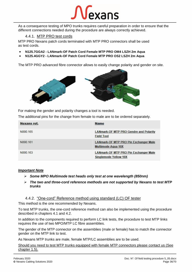
4.4.1. MTP PRO test cords
MTP PRO Nexans patch cords terminated with MTP PRO connectors shall be used as test cords.
• N125.7GGA2 - LANmark-OF Patch Cord Female MTP PRO OM4 LSZH 2m Aqua
• N125.4GGY2 - LANmark-OF Patch Cord Female MTP PRO OS2 LSZH 2m Aqua
The MTP PRO advanced fibre connector allows to easily change polarity and gender on site.
For making the gender and polarity changes a tool is needed.
The additional pins for the change from female to male are to be ordered separately.
Important Note
➢ Some MPO Multimode test heads only test at one wavelength (850nm)
➢ The two and three-cord reference methods are not supported by Nexans to test MTP trunks
4.4.2. “One-cord” Reference method using standard (LC) OF tester
This method is the one recommended by Nexans.
To test MTP trunks, the one-cord reference method can also be implemented using the procedure described in chapters 4.1 and 4.2.
In addition to the components required to perform LC link tests, the procedure to test MTP links requires the use of two MPO/MTP LC fibre assemblies.
The gender of the MTP connector on the assemblies (male or female) has to match the connector gender on the MTP link to test.
As Nexans MTP trunks are male, female MTP/LC assemblies are to be used.
Should you need to test MTP trunks equipped with female MTP connectors please contact us (See chapter 1.5).

February 2020 Doc. N°: Of field testing procedure 5_05.docx
Nexans Cabling Solutions 2020 Page 37/70
The use of MTP/LC Nexans assemblies is highly recommended.
LANmark-OF Pre-Term Female MTP – Simplex LC/PC Fan-out 100cm 12XOM4 1m Violet
P/N: N129.700V
LANmark-OF Pre-Term Female MTP/APC – Simplex LC/PC Fan-out 100cm 12XSM 1m Yellow
P/N: N129.400
This procedure has to be used when fibres have to be tested one at a time.
The same principle is applicable using a dual-fibre loss test set (also see chapter 4.2).
Step 1: Initial (LC) Reference
➢ Clean all fibre connections
• Dirt is harmful to connector and causes loss, which affect measurements.
• Always cover the connectors with a protection cap when not in use.
Nexans OF inspection and cleaning guide can be downloaded here
➢ The use of LC test cords terminated with reference grade connectors is required
➢ During the setup of the test tool
• select the Standard/limit to be applied: ISO 11801 (as for MTP/LC cassette testing – see chapter 4.3)

February 2020 Doc. N°: Of field testing procedure 5_05.docx
Nexans Cabling Solutions 2020 Page 38/70
• set the number of connectors to ‘2’ and the number of splices to ‘0’ for MM and SM trunks
• Set the refractive index of the fibre
• Set the method: One-cord reference
➢ Measure and record the initial reference at both wavelengths (set the reference)
See Important Notes on page 27
Step 2: Control – Test cords verification
Prior to starting link testing the two LC reference cords (launch and receive) need to be connected together and tested in order to demonstrate the quality of the cords and the correct measurement of the initial reference.
A singlemode adaptor shall be selected to connect the two cords together.
This control has to be performed every time the reference is re-established (several times a day).
Each test cord measurement performed during the testing of the fibre sub-system of the cabling shall be recorded.
The result should be
➢ < 0.15 dB when using MM reference grade cords
➢ < 0.3 dB when using SM reference grade cords
If these values are not obtained, redo the inspection and cleaning procedure for all the connectors on the two cords and re-establish the reference.
0.0 dB loss is acceptable but negative loss results (gain) are not acceptable.
Failed tests shall not be recorded.
Important Note
Test results submitted without related test cord measurements or with failed measurements cannot be accepted for warranty certification.

February 2020 Doc. N°: Of field testing procedure 5_05.docx
Nexans Cabling Solutions 2020 Page 39/70
Step 3: Test measurement of the MTP trunk
Clean all connectors.
Attach the two MTP/LC assemblies either side of the MTP link under test.
Note: The MTP/LC assemblies will have to be connected to the MTP link under test using two MTP adaptors and a second LC SM adaptor has to be added to connect the tail cord.
Loss limit
The loss limits are the same than for the test of MTP links terminated with MTP/LC cassettes (see chapter 4.4).
When testing MTP Nexans OF trunks
➢ always set the tester to test against ISO11801 limits
➢ Set the number of connectors to 2 and the number of splices to 0 for both MM and SM trunks
This will set the loss limit to 1.5 dB (2x 0.75) + the loss of the fibre
12 measurements will be required for every MTP link.
Notes
➢ Only 6 measurements needed if a dual-fibre loss test set is used (i.e. Fluke DSX)
➢ Depending on the polarity of the MTP trunk, fibres colour to be connected to the tester on each side can vary e.g. Port 1 TX side maybe in position 12 RX side.

February 2020 Doc. N°: Of field testing procedure 5_05.docx
Nexans Cabling Solutions 2020 Page 40/70
4.4.3. “One-cord” Reference method using MPO tester
The three following drawings show the one-cord reference procedure applied to the test of a trunk terminated on male connectors (Standard Nexans trunk).
This method is accepted but is not mandatory due to the lack of MPO testing capable devices currently available on the market.
Light
SourceEF
compliant
Power
Meter
-88.88 dBm
Reference power measurement
Not to be disrupted
once the reference
is set
Cord disconnection
end
One-cord
reference method
MTP/F
MTP/M
MTP/F
MTP/M
MTP adaptor MTP adaptor
Light
SourceEF
compliant
Power
Meter
-88.88 dBm
Control of the reference
To be recorded each time the reference is set
One-cord
reference method
MTP/F
MTP/M
MTP/F
MTP/M
MTP adaptor MTP adaptor
Power
Meter
-88.88 dBm
Test power measurement
Launch cord Tail cord
Link under test
One-cord
reference method
Light
SourceEF
compliant
MTP/F
MTP/M
MTP/F
MTP/M
MT
P/F
MT
P/M
MT
P/F
MT
P/M
MTP adaptor MTP adaptor

February 2020 Doc. N°: Of field testing procedure 5_05.docx
Nexans Cabling Solutions 2020 Page 41/70
Important Notes
1. This method (without any change of gender of the connector of the cords) can only be used if the MPO connectors on the power meter head has the same gender as the connectors on the link under test. It is generally the case as the power meters are most of the time equipped with male MPO connectors as the standard Nexans trunks are.
2. The reference power measurement is to be done with a female/female cord. To test a trunk with female MPO connectors the gender of the MTP PRO connector on one end of the launch and tail cords to be connected to the trunk would need to be changed from female to male to perform the test.
3. Test cord verification (test of the two test cords connected together to check cord performance) would require the gender of the connector of one of the cords to be changed and changed back to perform the test on a male/male link. Therefore, this control test is not requested to avoid the additional risk of contaminating the MTP connectors.
However a second step (See former page) is required to control the reference and record the time of the reference setup.
Loss limits
Due to the uncertainty of the method the measured loss of the two connectors can vary from -0.25 dB to 0.75 dB (Taking into account the loss variation of the two connectors of the link and of the connector of the power meter).
For OM3, OM4, OM5 and OS2 fibres the limit is set to
the loss of the two connectors (from -0.25 dB to +0.75 dB) + the loss of the fibre
Example: for a fibre loss of 0.2 dB the measured loss for each of the 12 fibres of the concerned trunk will be accepted from -0.05 dB to 0.95 dB.
See Important Note on page 8
Important Note
This loss limit will have to be manually set in the tester.

February 2020 Doc. N°: Of field testing procedure 5_05.docx
Nexans Cabling Solutions 2020 Page 42/70
5. OTDR testing - general information
OTDR Loss measurements have to be performed and interpreted by a qualified technician competent in the operation and analysis of OTDR result data.
Nexans Cabling Solutions will only consider OTDR traces submitted if the OTDR has been set-up correctly.
Traces have to be provided together with reports including at least the total loss of the link at both wavelengths and the “Pass/Fail” margin calculation.
However, it is the responsibility of the contractor to analyse every trace to ensure that the losses of the connectors, splices and fibre segments are lower than the maximum values defined by the Standards.
Nexans will only accept to certify links for which the total loss of the link and the loss of every component are all within the limits defined by the Standards.
PC software (with appropriate licenses – if applicable) needed to view, analyse and manage the results may be requested by NCS in order to process the warranty application.
NCS recommend the use of certifying OTDRs such as the Optifiber®PRO from Fluke Networks.
Example of acceptable and incorrect OTDR traces are provided in chapter 8.3
5.1. Attenuation (Insertion Loss) parameter
Fibre-optic tests apply to links and exclude equipment and work area cord.
The attenuation of the link is measured on the backscattered trace of the OTDR.
In accordance with ISO/IEC 14763-3 and ISO 61280-4-1 & ISO 61280-4-2 the use of a tail cord is required in order to get the full attenuation of the link including the fibre and both connectors of the link under test.
If the measured attenuation of the links has a lower value than the acceptable link attenuation calculated, the subsystem can be certified. If not, additional actions to rectify the problem will have to be taken.
Insertion Loss parameters, limits and acceptable link loss calculations: these are described in the Paragraph 3.2 to 3.4 for testing with ISO 14763-3 limits.
5.2. Field-testing equipment set-up and care
Spectral characteristics of OTDR equipment for testing MM and/or SM fibre cabling shall conform to the requirements of the ISO/IEC Standard.
The OTDR shall be configured for the specified wavelength and the appropriate settings for range, pulse width, index of refraction and averaging time.
The OTDR selected shall be capable of automatically displaying result information related to loss, length, link insertion loss, reflectance, (including identification of reflective versus non-reflective events and ghosts) as well as presenting event results in an event table.
Maintenance of the field instruments involves ensuring the adaptors and connectors are maintained in good condition. Follow the manufacturer’s guidelines to keep the rechargeable batteries in good condition and always store the instrument and equipment in a protective case.

February 2020 Doc. N°: Of field testing procedure 5_05.docx
Nexans Cabling Solutions 2020 Page 43/70
Software upgrades are relatively easy and often contain instrument performance improvements.
Software upgrades are usually obtained directly by downloading new executable files into a computer and transferring the files to the field instruments. It is a good idea to frequently check the manufacturer’s web site to ensure the field tester has the latest software and is up-to-date with the revisions to Standards limits.
LANmark Warranty submission:
For LANmark warranty certification, each link will need to be tested and submitted for verification.
Together with the submission form, the original OTDR traces for each link (in both wavelengths) in both direction, the and the measured link loss must be provided when applying for 25-year LANmark-OF warranty certification. In case of bidirectional measurement, all four traces have to be provided including the analysis of the traces and the average losses obtained from the two tests for both wavelengths.
N.B. Details relating to the settings for range, pulse width, index of refraction and averaging time must also be included.
If the OTDR does not provide test result analysis features, the original trace files must be sent to Nexans together with one completed NCS OF Complementary Warranty Application Data Form per cable assembly. Make sure the same link references between the trace files and the complementary form are used.
The negative loss values must be entered into the complementary OF form by typing a ‘-‘ sign before all the values for both wavelengths.
In each trace the fibre under test including the connections should be clearly visible. NCS will not accept traces where the event dead zones of connections are overlapping each other.
More information can be found in chapter 8. 2 and 8.3

February 2020 Doc. N°: Of field testing procedure 5_05.docx
Nexans Cabling Solutions 2020 Page 44/70
6. OTDR testing procedures
The test procedure described below is compliant with ISO/IEC 14763-3 2nd edition: 2006 and ISO/IEC 61280-4-1 2nd edition and ISO/IEC 61280-4-2 2nd edition
The use of a tail (or receiving) cord is required in order to obtain the full attenuation characteristic of the link under test, including the fibre loss and the loss of both connectors.
Tail cord
Link under test
Launch
cord
The trace shows the measurement of a link connected to a launch and a tail cord - the losses of the two connections and of the fibre are therefore correctly measured. The total loss of the link will be the total of the three losses highlighted in the red circles on the event table.
The attenuation of the fibre segment is acceptable: 2.458 dB/km at 850nm (< 3.5dB/km)
The two spliced pigtails on both sides of the link (event 2 and 3) also have an acceptable loss (< 0.6 dB for each – 0.3 for the connector + 0.3 for the splice)
The total loss of this link will be: 0.398 + 0.313 + 0.158 = 0.87 dB
The total loss is acceptable: 0.87 dB < 1.64 dB = (0.127 km x 3.5) + 2x (0.3 + 0.3)

February 2020 Doc. N°: Of field testing procedure 5_05.docx
Nexans Cabling Solutions 2020 Page 45/70
Without a tail cord
➢ You can only measure the attenuation of the fibre and of the near end connector.
➢ The continuity (or polarity) test is not performed
Link under test
Launch
cord
?
The trace shows the measurement of a link with only a launch cord connected. The losses of the near end connection and of the fibre are measured but not the loss of the far end connection.
As a consequence the total loss of the link cannot be calculated and the quality of the far end splice and pigtail are unknown.
Important Note
Moreover, if the far end pigtail is defective or connected on the wrong adaptor of the patch panel (polarity error), this problem will not be detected.
NCS will not accept OTDR measurements performed without tail cords.
6.1. Direction of measurement NCS mandates bidirectional measurement (testing in both directions).
With bidirectional measurement the insertion loss value is achieved by calculating the mean of the two results.
The resulting mean trace calculated from the two measurements by the OTDR software, has to be provided together with the bidirectional measurement (3 traces at both wavelengths for each OF link) – the value of the mean trace must obviously meet the required Nexans loss limit.

February 2020 Doc. N°: Of field testing procedure 5_05.docx
Nexans Cabling Solutions 2020 Page 46/70
Important Note
When conducting such bidirectional measurement the launch and tail cords shall remain on the same side of the link. Only the OTDR shall be moved to the far end.
If the launch and tail cords are swapped over, the calculation of the loss mean value will not be correct because the two connectors forming the connection will be different in both measurements.
Moreover, the software would not be able to calculate the mean trace if the length of the launch and tail cords are different (mated connectors events would be seen at different length locations on the two measurements).
6.2. Materials needed
To test optical fibre links using OTDR equipment, you will need the following items:
➢ Dual wavelength fibre-optic OTDR
Wavelengths: 850 & 1300 nm for MM fibres / 1310 & 1550 nm for SM fibres
➢ Launch and tail fibre cords (SC, LC …) and fibre types (MM, SM) compatible with the OF subsystem to be tested.
These cords shall be maintained in good order and regularly tested. The test cords for OTDR testing shall be longer than the attenuation dead zone of the OTDR
The following settings are required.
MM Fibre link length < 300m
MM Fibre link length > 300m
SM Fibre link length < 500m
SM Fibre link length > 500m
Launch and Tail cord length
50 – 150 m 50 – 300 m 200 - 500 m 500 – 1000 m
Maximum Pulse width
3 or 5 ns 10 ns 10 ns 20 ns
Range 1000 m 2000 – 3000 m 2000 m 3000 – 5000 m
Launch and tail cords shall be terminated with reference grade connectors.
As for LSPM testing, the limits to be applied is:
• ISO 14763-3:2006 using launch and tail cords terminated on reference grade connectors
➢ Mating adaptors for connectors (couplers)
➢ Lint free cleaning wipes and pure isopropyl alcohol or specialised OF cleaning fluid. Dust in the air can be as big as the core of a SM fibre and big enough to cause high loss in MM fibre.
Important Note
Always clean connectors before testing or patching
Nexans OF inspection and cleaning guide can be downloaded here
➢ A fibre scope (VFL) This tool will be useful to inspect the connectors and for trouble-shooting

February 2020 Doc. N°: Of field testing procedure 5_05.docx
Nexans Cabling Solutions 2020 Page 47/70
➢ NCS OF Complementary Warranty Application Data Form. To be filled in if the OTDR doesn’t provide “Pass-Fail” analysis features
The above-mentioned document can be downloaded from our website:
Warranty section of our library
6.3. Test tool configuration
Check the fibre test set to be sure it is fully functional, the battery is charged, and all the necessary equipment including ancillaries is available.
Inspect the cord connectors for any damage and cleanliness. NCS recommend the use of a fibre scope to perform this inspection.
The scattering characteristics of the fibre within the launch and tail cords shall be the same.
Calibration and set-up
Calibration and set-up procedures vary per field tester.
Check with the field tester documentation for the correct procedure.
The OTDR shall be selected for the right mode/wavelengths and the appropriated settings established for
➢ Range
➢ Pulse Width
➢ Averaging time.
➢ Index of Refraction (IOR)
The Index of Refraction of a fibre, is a characteristic that may vary from one OF manufacturer to another. Here are the values to be used with the Nexans fibres.
Note
The IOR of the Nexans fibres are generally recorded in the manufacturers’ database of the tester.
Selecting a Nexans fibre in this database will therefore automatically set the IOR to the right figure.
Index of refraction of LANmark-OF fibres
Optical Fibre type 850 nm 1300 nm 1310 nm 1550 nm
Multimode 50 µm (OM3, OM4, OM5) 1,482 1,477 NA NA
Singlemode (OS2) NA NA 1,466 1,467

February 2020 Doc. N°: Of field testing procedure 5_05.docx
Nexans Cabling Solutions 2020 Page 48/70
6.4. Testing
Clean all fibre connections
➢ Dirt is harmful to connector and causes loss, which affect measurements. ➢ Always cover the connectors with a protection cap when not in use.
Nexans OF inspection and cleaning guide can be downloaded here
Step 1: Control – Test cords verification
Prior to beginning testing any links Nexans request to first test the two cords (launch and tail) connected together in order to demonstrate the good quality of the cords and the correct measurement of the reference.
OTDR
Measurement cords test to be recorded
Tail cordLaunch cord
SM coupler
A singlemode adaptor shall be selected to connect the two cords together.
The result should be
➢ < 0.15 dB when using MM reference grade cords
➢ < 0.3 dB when using SM reference grade cords
If these values are not obtained, redo the inspection and cleaning procedure for all the connectors on the two cords and re-establish the reference.
0.0 dB loss is acceptable.
Failed tests shall not be recorded.
Test results submitted either without related test cord measurements or with failed measurements cannot be accepted.

February 2020 Doc. N°: Of field testing procedure 5_05.docx
Nexans Cabling Solutions 2020 Page 49/70
Step 2: Control – link test in the first direction
The launch cord shall be connected between the OTDR and the cabling link under test.
The tail cord shall be connected to the remote end of the cabling under test.
OTDR
A
L (m)
LC
F (dB)
TC Permanent Link under test
L
C1 C2
C3 C4
C5
L1
The attenuation or loss of the installed cabling includes two connections and the fibre loss.
The drawing shows correct placing of cursors on OTDR traces for link insertion loss measurement.
Wherever possible the more accurate 5 cursor method is to be used as this gives results that have no dependence on pulse width, dead zones etc.
Note that the vertical scale has been expanded to make the precise cursor positioning and resultant loss measurements clearer (this is good measurement practice).
For examples of acceptable and wrong OTDR measurements, please see 8.3

February 2020 Doc. N°: Of field testing procedure 5_05.docx
Nexans Cabling Solutions 2020 Page 50/70
Step 3: Control – link test in the opposite direction
Move the OTDR to the far end of the link and test the link in the other direction.
Note: Moving the OTDR tester on the other far end can also be done after the first testing sequence of all the fibres in the first direction.
Important Note
When conducting such bidirectional measurement the launch and tail cords shall remain on the same side of the link. Only the OTDR shall be moved to the far end.
If the launch and tail cords are swapped over, the calculation of the loss mean value will not be correct because the two connectors forming the connection will be different in both measurements.
Moreover, the software would not be able to calculate the mean trace if the length of the launch and tail cords are different (mated connectors events would be seen at different length locations on the two measurements).
Step 4: Post-treatment of the test results
The resulting mean trace shall be calculated from the two measurements by the OTDR software.
This mean trace has to be provided together with the bidirectional measurement (3 traces at both wavelengths for each OF link) – the value of the mean trace must obviously meet the required Nexans loss limit.
Depending on the OTDR you are working with
- the mean trace can be automatically produced by the OTDR
- the mean trace calculation can have to be performed using the PC software provided together with your OTDR
- The loss of every component of the link (Fibre / connection on both ends) can have to be calculated by the operator using the PC software provided together with your OTDR. In this case the mean values shall be manually calculated
The NCS OF Complementary Warranty Application Data Form shall be filled in if the OTDR doesn’t provide “Pass-Fail” analysis features (See chapter 8.2).

February 2020 Doc. N°: Of field testing procedure 5_05.docx
Nexans Cabling Solutions 2020 Page 51/70
7. Troubleshooting
A test failure is a measurement failure and could be caused by the cabling, the field instrument, poor installation practices, or a combination of these. Depending upon the test that failed, several diagnostic alternatives may be available. Before attempting any changes to the cabling, always ensure that the field tester is providing accurate results and that the correct test configuration has been set up.
➢ The presence of dust, dirt and other contaminants at the interfaces to the cabling under test may produce misleading results and in some cases damage plug end faces on the link under test and/or on the test adaptor. The mating connector end faces of cabling interface adaptors and the cabling under test shall be cleaned in accordance with the connecting hardware manufacturers instructions prior to mating.
➢ Always clean the fibre end faces before making any connections. Use lint-free swabs or wipes moistened with pure isopropyl alcohol or pre-moistened wipes approved for use in fibre connectors.
Nexans OF inspection and cleaning guide can be downloaded here
➢ If no power is measured at the source, the optical source or the patch cords could be defective.
➢ If the power loss is more than expected or if no power is measured
Fibres could be connected to the wrong port of the unit
Fibres could be swapped at one end of the link
A patch cord could be broken
There could be one or more dirty connections in the link
Parameters in the tester could be wrongly set-up.
Patch cord(s) and fibre from the link could have a different core size
➢ If the measure of the length of cable is too long or too short, the index of refraction could have been set up incorrectly.
UNDER NO CIRCUMSTANCES EVER look into an active optical fibre (especially with a microscope not equipped with safety filter) as harmful radiation that can cause eye damage may be present.

February 2020 Doc. N°: Of field testing procedure 5_05.docx
Nexans Cabling Solutions 2020 Page 52/70
8. ANNEXES
8.1. Normative references
This testing procedure complies with the following International Standards:
ISO/IEC 11801 Generic cabling for customer premises
Edition 3 - 2017 /Cor 1:2018
ISO/IEC 14763-3 Implementation and operation of customer premises cabling –
Part 3: Testing of optical fibre cabling
Edition 1 - 2006
IEC 61280-4-1 Test procedures for fibre optic cable plant and links -
Multimode fibre optic cable plant attenuation measurement
Edition 3 – 2019
IEC 61280-4-2 Test procedures for fibre optic cable plant and links –
Single mode fibre optic cable plant attenuation measurement
Edition 2 – 2014
IEC 61280-4-5 Test procedures for fibre optic cable plant and links -
Attenuation measurement of MPO terminated FO cable plant using test equipment with MPO interfaces
Edition 1 – CD draft 2019

February 2020 Doc. N°: Of field testing procedure 5_05.docx
Nexans Cabling Solutions 2020 Page 53/70
8.2. OF Complementary Warranty Application Data Form
If the OTDR or the MPO loss test set don't provide test results storage and analysis features, the measurements must be transmitted to NCS using the NCS complementary OF Warranty Application Data Form.
OF Warranty Application Data Form explanation
The Excel data form contains 3 worksheets:
➢ Data collection: legend, procedure summary and 14 data fields to be completed
➢ Test report 1: measurement at the first wavelength (850nm for MM and 1310 for SM)
➢ Test report 2: measurement at the second wavelength (1300nm for MM and 1550 for SM)
The file is foreseen to report the test of one complete OF link: 2 to 24 fibres.
A 96 fibres version of the form is also available.
Tests can have been performed using LSPM or OTDR test equipment.
One report file has to be created and saved for every OF cable whatever the fibre quantity.
The cells are coloured to highlight the ones that have to be filled-in:
Explanation / Description
Automatic calculation
Value to be selected from a list
(to view data list, click on the arrow when cell is selected)
To be filled-in
On the first sheet (data collection), there are 14 fields to be filled-in: tan and white cells.
All these cells shall be filled-in because these values are used to automatically populate several cells from the second and third sheet and automatic calculation are resulting of the values set in these fields.
The calculation of the acceptable link loss is automatically carried out according to the fields filled-in on the data collection sheet.

February 2020 Doc. N°: Of field testing procedure 5_05.docx
Nexans Cabling Solutions 2020 Page 54/70
The margin and the Pass/Fail fields are also automatically calculated once the measured values have been typed in the corresponding cells. Fails are highlighted in red.
1. Date: type the date of the test.
2. Type of test cords: select the value from the drop-down list.
After selecting the cell, click on the arrow to obtain the drop-down list.
“MTP cords” shall be selected if the form is related to MTP trunk testing (see chapter 4.5).
For all other tests results including MTP links terminated with cassettes, select “reference grade cords” or “Nexans cords”.
3. The green cell of row three (ISO Standard limits) will be automatically updated according to the type of test cord selected. The calculation of the link loss limits will also be automatically updated.
4. Select the testing method used.
LSPM 3-cord reference method shall only be selected for MTP trunk testing.
LSPM One-cord reference can also be used for MTP trunk testing (not recommended – see chapter 4.5)
5. Select the type of fibre installed.
The wavelength indicated on the two next worksheets and the calculations will be automatically updated:
• 850nm and 1300nm for multimode fibres
• 1310nm and 1550nm for singlemode fibres
6. Select the link connector type used.
MTP/MPO connector shall only be selected for MTP trunk testing. When testing MTP links terminated with LC or SC cassettes, LC or SC shall be selected.

February 2020 Doc. N°: Of field testing procedure 5_05.docx
Nexans Cabling Solutions 2020 Page 55/70
7. Select the type of termination.
For MTP trunk testing it is important to select “MTP trunk” as it will affect the link loss limit automatic calculation.
8. Select the number of splices included in the link.
The pigtails splices terminating the link shall not be included in the number.
9. Select the right value depending on the design of the link (with or without MPO/MTP cassettes)
“None” shall be selected for MTP to MTP trunk testing.
10. Select the type of OF cable structure.
11. Type the length of the link under test. This value can be provided by your test equipment.
If not, look at the meter marking printed on both ends of the cable and subtract the two figures.
The length is an important parameter to calculate the loss limit of the link on pages 2 and 3.
12. Type the name or label of the link
13. Type the project name
14. Type the customer name
15. Type the name of your company
On the two last sheets (test reports 1 & 2), only the white cells have to be filled in with the measured power values: reference value (P1) + the far end measurement.

February 2020 Doc. N°: Of field testing procedure 5_05.docx
Nexans Cabling Solutions 2020 Page 56/70
The reference value is the same for all measurements performed on all fibres of the same link (one value for each test report sheet).
Note: The reference value will be different for each wavelength.
Example of filled-in table
Note: A Fail result shall be investigated, reworked and retested.
If you set the reference measurement (P1) to zero in your tester, enter '0' in the reference power measurement cell from sheet 2 and 3. When using the zero reference feature, your tool has already performed the P1-P2 calculation. That's why the reference power has to be set to 0.
This way of filling in the form is recommended for OTDR test reporting. See chapter 6 for an example of loss calculation.

February 2020 Doc. N°: Of field testing procedure 5_05.docx
Nexans Cabling Solutions 2020 Page 57/70
Power measurements are expressed in negative dBm (0 dBm = 1 mW / LED output power is typically around -20 dBm).
Important Notes
1. To ensure that the automatic calculations provide correct values, always type the figures with their minus sign.
2. The P2 value shall always be lower than the P1 value. In other words you always have to get a loss.
Zero loss results or gains definitely need to be immediately investigated.
You should never have a gain. If so it would mean that more power is received at the end of the fibre than the power level injected into the fibre. This is obviously not possible and can only result from a measurement error.
For LSPM testing, if you get positive margin it most probably means that the reference measurement is wrong and shall be re-measured after inspection and cleaning of all the connectors.
For OTDR testing it most probably means that you didn’t perform bidirectional testing or you are not calculating the loss from the mean trace.
3. Fail results will not be accepted for warranty applications. A Fail result shall be investigated, reworked and retested.
Tip
When printing, if you select the 3 worksheets beforehand (click on the first one and shift + click on the third one), it will be numbered from 1/3 to 3/3.
File protections
“Not to be filled cells” are locked to prevent accidental erasing of the formulas.
The Excel file itself is also protected: read only protection.
When opening the password protected file, a window will pop-up (see below). Click on the ‘read only button’ to open the file in read only mode.
You can then save your files under a different name.
To save your file, select File, “Save As” and change the file name.

February 2020 Doc. N°: Of field testing procedure 5_05.docx
Nexans Cabling Solutions 2020 Page 58/70
8.3. OTDR trace analysis and link loss calculations
In addition to the information provided in chapter 6 regarding testing, in this chapter examples are given of acceptable and incorrect OTDR measurements.
Screenshots of traces provided to help explain, are helpful in order to understand the Nexans requirements and so avoid the rejection of the measurements submitted together with the warranty application.
In order to avoid potential processing delays and re-testing requirements, any results requiring Nexans warranty certification must be checked for correct set-up and expected
measured performance levels, prior to submitting to Nexans.
It is advised that analysis of every trace, to confirm acceptability, shall be performed by the operator immediately after each measurement rather than waiting to review every result when the testing of all lines has been completed. If analysis is only undertaken when all
testing has been completed and a generic issue is then identified, the complete install may need to be re-tested.
Please be aware that should results with an incorrect test set-up be submitted for warranty certification, they will have to be rejected as the results will not be representative of the installed line characteristics / performance profile - re-testing will therefore need to be
undertaken. This will obviously be a very costly exercise and some lines by that time may not be accessible for re-testing. This may mean that some or all lines would have to be
excluded from warranty certification.
In some circumstances it may not be possible to establish absolute loss measurement values for each component e.g. when the link length is extremely short. In such circumstances, provided the component measurement is undertaken correctly and the result is well within the applicable component loss limit and the overall link loss result is within the appropriate pro-rata link limit, then the results will be accepted.
Note
The following information is not intended to replace OTDR technical information or operating and analysis training that is supplied or recommended for example by the OTDR manufacturers.
Nexans highly recommend contractors to attend such official training in order to acquire the necessary knowledge regarding the usage of their own OTDR(s).
Understanding of the following information requires at least a basic knowledge of OTDR testing methodology.
Trace example 1: 5 and 10ns pulse widths
The two following measurements (see next page) have been performed using a different pulse width: 5ns for the first one and 10ns for the second one. All other parameters are identical.
Obviously the accuracy of the trace 1-1 is reduced due to the noise present on the graph.
The difference in the level of noise is due to the fact that the level of power injected in the fibre is lower when the pulse width is reduced.
However both traces are acceptable.
The level of noise in the first trace does not dramatically affect the measurement of the losses regarding the events 2 & 3 and of the fibre under test.
The pulse width of the second trace is larger but is still providing the requested resolution to be able to properly check the events and fibre losses.
In LAN applications, 2ns, 5ns or 10ns are the most recommended pulse widths due to the reduced length of the fibre. Measurement of very short links (e.g. below trace 6-2) requires the test to be performed using the shorter pulse width (2 or 5ns). Should the length be really short (a few metres)

February 2020 Doc. N°: Of field testing procedure 5_05.docx
Nexans Cabling Solutions 2020 Page 59/70
OTDR testing is not recommended as overlapping of the event dead zones will become unavoidable and as a consequence an accurate link loss calculation will not be possible.
Note: please see trace example 5 re overlapping dead zones
Note: a larger pulse width (e.g. 20 or 50ns) is required to measure long link lengths (e.g. those more than 500 metres).
Trace 1-1
Trace 1-2

February 2020 Doc. N°: Of field testing procedure 5_05.docx
Nexans Cabling Solutions 2020 Page 60/70
Trace example 2: Adapt the range to the length of the fibre under test
It is recommended to select the best range possible according to the length of the fibre under test.
In the following examples the trace provided by the second measurement is obviously more adapted to the length of the link under test.
The readability of the second trace (range of 250m) is better than for the first trace. The range of 1200m is obviously too large for the short fibre and test cords.
Traces results should be optimised in respect to screen width as per 2-2.
Note: results submitted as per 2-1 may be rejected.
Trace 2-1
Trace 2-2

February 2020 Doc. N°: Of field testing procedure 5_05.docx
Nexans Cabling Solutions 2020 Page 61/70
Trace example 3: High reflectance of a connection
The level of reflectance of the connections shall be carefully checked.
High reflectance will blind the receiver of the OTDR. The device will be saturated by the amount of light reflected back by the wrong connection.
As a consequence, the dead zone duration will increase (due to the very long recovery time needed by the receiver) and the trace slope (b) will be an incorrect representation of the actual performance. Therefore it will not be possible to accurately measure the losses of the event(s) and of the fibre.
Here are two examples of unacceptable traces. The issue is due to the fact that the connectors are not touching each other. There is a gap between the end faces of the two fibres generating these high reflexions (a). The cleaning of the connectors is required.
Trace 3-1
Trace 3-2
(a)
(b)
(a)
(b)

February 2020 Doc. N°: Of field testing procedure 5_05.docx
Nexans Cabling Solutions 2020 Page 62/70
Trace example 4: High loss of an event
The loss of the event 3 (trace 4-1 - far end link connection) is obviously out of limit: > 0.75dB – with measurement cords equipped with standard grade connectors - and is therefore not acceptable.
Trace 4-1
The loss of the event 2 in the trace 4-2 is not acceptable (0.506 dB) because the measurement is performed with cords terminated with reference grade connectors
Trace 4-2
Note: the launch cord is short but acceptable as the event 1 dead zone doesn’t affect the measurement of the event 2 (first connection of the fibre under test) - No overlapping of the dead zones

February 2020 Doc. N°: Of field testing procedure 5_05.docx
Nexans Cabling Solutions 2020 Page 63/70
Trace example 5: Wrong OTDR setting
The following trace is resulting from a measurement performed with a pulse width of 100ns. Obviously the width of the pulse is too large to get a correct measurement of the two events located close to each other. The second event of the group (just after the event 2) is not automatically detected (due to the overlapping of the two events dead zones) and is therefore not listed in the event table.
The measurement result is obviously not acceptable.
Note: the events also have a very high (and unacceptable) level of reflection.
Trace 5-1

February 2020 Doc. N°: Of field testing procedure 5_05.docx
Nexans Cabling Solutions 2020 Page 64/70
Trace example 6: Positive loss or gain
The following trace is typical of a measurement performed with measurement cords (launch and tail cords) having different backscatter characteristics than the fibre under test.
The first connection (event 2) shows a gain. The measurement provides a false result as it is not possible to have a positive loss / gain.
The second connection (event 3) shows a high loss highlighted in red as it is out of limit (> 0.75dB).
It is not possible to improve the measurement (except if the measurement cords are replaced by others having backscatter characteristics that better match the one of the fibre under test).
Bidirectional measurements of all the fibres have to be performed. The loss of the events and of the fibre will be provided by the mean of the two measurements. OTDR software is generally able to calculate that mean trace (see end of chapter 5.3: Direction of measurement).
Positive gain should not remain on mean trace and is not acceptable
Note
The gain of -0.571 dB (event 2) is (wrongly) considered as being acceptable by the tool because it
is not exceeding the limit (+0.75 dB).
Important Note
It highlights the importance for the operator to analyse every trace just after the test as the software automatic analysis feature is not able to detect every potential issue.
Trace 6-1

February 2020 Doc. N°: Of field testing procedure 5_05.docx
Nexans Cabling Solutions 2020 Page 65/70
Despite the two loss measurement potential issues (positive loss of the event 2 and wrong linear loss of the fibre under test) the following trace is acceptable.
Very low gain close to - 0.1 dB can be accepted if the second connection of the link doesn’t have an out of limit loss and if obviously the traces submitted shows correct setting of the OTDR and consistent and trustful measurements of all the fibres.
The linear loss of the fibre under test is out of limit (over 1.5dB/km). However, the fibre to be measured is so short (10.8m) that the linear loss provided by the OTDR is inaccurate because it is very difficult for the OTDR to define the slope on such a short line.
The test settings are correct and there is no overlapping of the two events dead zones.
Trace 6-2

February 2020 Doc. N°: Of field testing procedure 5_05.docx
Nexans Cabling Solutions 2020 Page 66/70
Link loss calculation
Software provided by OTDR manufacturers will provide the loss measurement mainly in three different ways.
1. Some certifying OTDR will provide a complete set of information including the total loss of the link and the Pass/fail analysis.
Flukenetwork OptiFiber® Pro OTDR
No post processing of the test result is required. When submitted together with the filled in warranty application form, Nexans will accept these test results without requiring any additional information.
2. Some other OTDR software will provide a trace and a table of event including the loss of every element of the link but will not provide the total loss of the link and the Pass/Fail analysis (see detailed information in chapter 6).
EXFO OTDR

February 2020 Doc. N°: Of field testing procedure 5_05.docx
Nexans Cabling Solutions 2020 Page 67/70
In this case Nexans request the Complementary Warranty Application Data Form to be filled-in for every link of the fibre sub-system. The total loss of every fibre has to be calculated and recorded in the form for both wavelengths (see detailed information in chapter 8.2). The Pass/ Fail information will automatically be calculated by the Nexans form.
3. Finally, some analysis and reporting software tools for optical tests can provide a trace and a table of events but unfortunately not the loss of every element of the link.
As shown on the screenshot below, the table of events is only providing the cumulative loss at each detected event.
The cumulative loss just before the near end connector of the link is 0.346 dB and the cumulative loss value just before the far end connector of the link is 0.519 dB
The difference between these two values (0.519 – 0.346 = 0.173 dB) will provide the loss of the fibre and of the near end connector.
The loss of the far end connector has to be added to calculate the total loss of the link: 0.173 + 0.536 = 0.709 dB
Nexans therefore requires the Complementary Warranty Application Data Form to be filled-in for every link of the fibre sub-system. The total loss of every fibre has to be calculated and recorded in the form for both wavelengths (see detailed information in chapter 8.2). The pass/ fail information will automatically be calculated by the Nexans form.

February 2020 Doc. N°: Of field testing procedure 5_05.docx
Nexans Cabling Solutions 2020 Page 68/70
8.4. Fibre Optic cabling compliance testing requirements
After installation, links must be tested for compliance with the normative requirements in order to validate the installed cabling.
In accordance with the applicable Standards (refer to §3.2), the end-to-end optical attenuation has to be tested for all installed FO links as a means of validating the FO cabling subsystem.
This value has to be calculated in accordance to the specifications within ISO 14763-3:2006.
To pass the test, the measured attenuation of a FO link should always be lower than the acceptable link loss value calculated for this link.
Link performance
If all the links pass test, the FO subsystem will be validated but the warranted performance can vary according to the characteristics defined during the design (see Important Note on page 8).
Channel performance
Applications requiring a high bandwidth (example: 10 Gigabit network applications) will only be warranted if the following elements have been chosen according to the specific needs of the customer:
A: Optical fibre type: OM3, OM4, OM5, OS2
B: The link length and loss are compliant with the application Standard limits
Also refer to the Important Note on page 8 (chapter 2.2).
8.5. Acceptable link loss calculation with ISO 14763-3
The measured value of attenuation of a FO link should not exceed the sum of allowable attenuation of each component of the link. These components are the ➢ cable ➢ connector terminations ➢ splices (if any)
The specifications within the ISO 11801 Standard are representative of the following formulas
Link loss (dB) = Cable loss + Connectors loss + Splices loss
Cable loss (dB) = Cable length (km) x Loss coefficient (dB/km) *
Connector loss (dB) = number of connector pairs x connector loss (dB) **
Splice loss = number of splices x splice loss (dB) *
*: from chapter 3.3 – Common attenuation limits
**: from chapter 3.4 and 3.5 – Connector attenuation limits

February 2020 Doc. N°: Of field testing procedure 5_05.docx
Nexans Cabling Solutions 2020 Page 69/70
Examples
1. Link loss for 84 meters of OM3 fibre terminated on field installable SC connectors
Tested with reference patch cords (terminated with reference grade connectors) ISO14763-3:2006 limit apply for the loss of the connectors
Cable loss at 850nm: 0.084 km x 3.5 dB/km = 0.3 dB Connector loss: 2 x 0.3 dB = 0.6 dB Splice loss: 0 x 0.3 dB = 0.0 dB Acceptable Link Loss = 0.9 dB
2. Link loss for 350 meters of OM4 fibre terminated on LC pigtails
Tested with reference patch cords (terminated with reference grade connectors) ISO14763-3:2006 limit apply for the loss of the connectors
Cable loss at 1310nm: 0.350 km x 1.5 dB/km = 0.5 dB Connector loss: 2 x 0.3 dB = 0.6 dB Splice loss: 2 x 0.3 dB = 0.6 dB Acceptable Link Loss = 1.7 dB
3. Link loss for 500 meters of OS2 fibre terminated on LC pigtails
Tested with reference patch cords (terminated with reference grade connectors)
ISO14763-3:2006 limit apply for the loss of the connectors
Cable loss at 1550nm: 0.5 km x 0.4 dB/km = 0.2 dB Connector loss: 2 x 0.5 dB = 1.0 dB Splice loss: 2 x 0.3 dB = 0.6 dB Acceptable Link Loss = 1.8 dB
4. Link loss for 250 meters of OM3 MTP link terminated with MTP/LC cassettes
Tested reference grade patch cords
ISO11801 limit apply for the loss of the cassettes (0.75 dB per cassette)
Cable loss at 850nm: 0.200 km x 3.5 dB/km = 0.7 dB Cassettes loss: 2 x 0.75 dB = 1.5 dB Acceptable Link Loss = 2.2 dB

February 2020 Doc. N°: Of field testing procedure 5_05.docx
Nexans Cabling Solutions 2020 Page 70/70
8.6. Index of Refraction of NCS LANmark-OF fibres
The Cable length shall be optically measured or calculated using cable sheath length markings.
The length measurement can be performed with the LSPM loss test set or with the Optical Time Domain Reflectometer (OTDR).
The refractive index of the fibre to be tested has to be set to the right value on the LSPM and OTDR test equipment as the instruments need this parameter to calculate the correct cable length.
Index of refraction of LANmark-OF fibres
Optical Fibre type 850 nm 1300 nm 1310 nm 1550 nm
Multimode 50 µm (OM3, OM4, OM5) 1.482 1.477 NA NA
Singlemode (OS2) NA NA 1.466 1.467
Note
The IOR of the Nexans fibres are generally recorded in the manufacturers’ database of the tester.
Selecting a Nexans fibre in this database will therefore automatically set the IOR to the right figure.
Disclaimer
This document is a guideline only. International and local procedures and safety Standards must be observed
and followed at all times.
Nexans Cabling Systems will not be held liable for any damage or injury to personnel, equipment or business
directly or indirectly as a result of using this document in part or in whole.
The practices contained herein are designed as a guide for use by persons having the required technical skill at
their own discretion and risk. The recommended practices are based on average conditions. Nexans does not
guarantee any favourable results or assume any liability in connection with this document.
Nexans does not assume any responsibility for the accuracy or completeness of this document.
The user should review the information to ensure conformity to the current applicable codes and regulations and
to the project requirements.
Nexans reserves the right to change the technical specifications at any time without notice.
Edition 04.02.2020
Copyright © Nexans 2020
All data subject to change
without prior notice.