fiberstars lighted laminar flow fountain … laminar flow fountain installation manual . ... each...
TRANSCRIPT
79-15037-00 REV Xx http://www.fiberstars.com Page 1 of 8
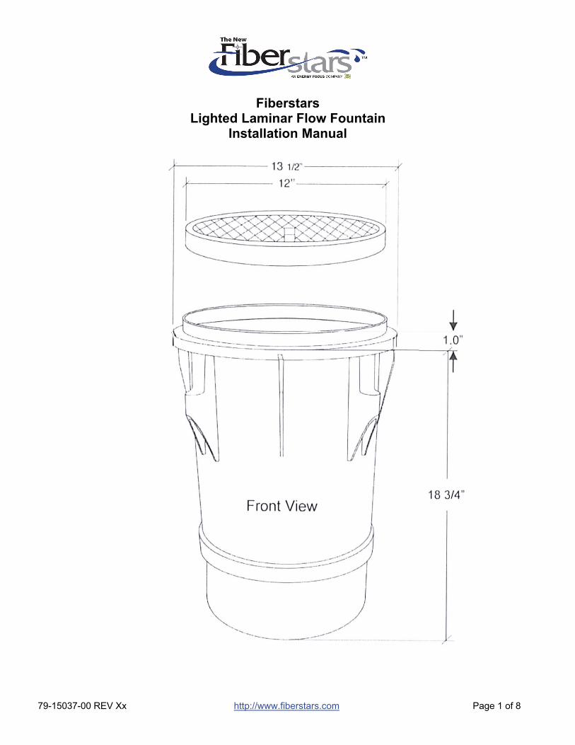
Fiberstars
Lighted Laminar Flow Fountain Installation Manual
79-15037-00 REV Xx http://www.fiberstars.com Page 2 of 8
SAVE THESE DIRECTIONS!
These directions are provided to ensure the proper installation and operation of Fiberstars Large Lighted Laminar. The maximum lighted distance of the laminar stream should be considered 6ft height and 6ft in distance. If the laminar arc is over 6ft there is a high degree of probability that the lighting will not travel the full distance to the bottom of the laminar flow. Also, if the throw distance is over 6ft, the lighting will also fail to go the full distance of the laminar stream.
IMPORTANT:
Read and follow all safety and installation instructions carefully before installation.
The product must be installed in accordance with the applicable installation code by a person familiar with the construction and operation of the product and hazards involved.
IMPORTANT GENERAL SPECIFICATIONS:
1. The water supply to the Lighted Laminar fountains must be filtered with a cartridge
filter. Sand filter and DE filters will likely produce small particles of debris that will clog the filter screens internal to the laminar flow fountains.
2. Water supply is dependent upon 3 important factors:
a. Pump size – if dedicated pump is used it must be a minimum of a ½ hp and supply proper flow rate at 16 ft of head.
b. Plumbing pipe size c. Number of laminar flow fountains on the system
GENERAL RULE OF THUMB IS THAT EACH LAMINAR REQUIRES A MINIMUM OF 10 GPM. SEE FOLLOWING SECTION ON DESIGN CRITERIA.
THE LAMINAR FLOW DECK BOX IS MADE OF ABS MATERIAL. USE ONLY ABS-PVC GLUE WHEN MAKING ANY CONDUIT CONNECTIONS TO THIS DECK BOX.
3. Each Fiberstars Lighted Laminar flow fountain contains 150 strand of fiber cable. Minimum Recommended sized conduit is 1” reduced to ¾” at the deck box. Always use sweep 90’s to allow the fiber to be pulled easily through the conduit.
4. Fiberstars Color Light Streams Large Laminar flow fountains can be placed in most any
location from concrete decks, raised bond beams or even softscapes. Be sure that the distance from the interior pool wall to the laminar flow fountain is no further than 5’. This would allow the lighted laminar flow stream to be 1’ into the pool interior.
5. Each fountain requires a 1” (see table on page 5 for pipe size progression) PVC water
supply that will be glued to the supplied reducer that connects the PVC flex inlet hose.
79-15037-00 REV Xx http://www.fiberstars.com Page 3 of 8
6. Each laminar may also have an individual, optional gate valve installed for minor flow adjustments. All main flow gate valves should be located as close as possible to the equipment pad area to reduce water turbulence from entering the laminar fountain.
7. On main water supply line install a cartridge filter and check valve.
8. Bypass line and main flow gate valve needs to be installed.
9. A plumbing loop is highly recommended for multiple fountain installations. INSTALLATION OF THE LAMINAR FLOW DECK BOX
1. Reconfirm that fountain is no further than 5 feet away from the interior water surface of the pool.
2. Prepare location by digging hole approx. 24” in diameter and 30” deep.
a. For ‘in-deck’ applications – Level the lid to the finished grade level of decking. b. For planter areas – Laminar lid should be 2 inches ABOVE the landscape area to
prevent materials from intruding or washing into the fountain itself.
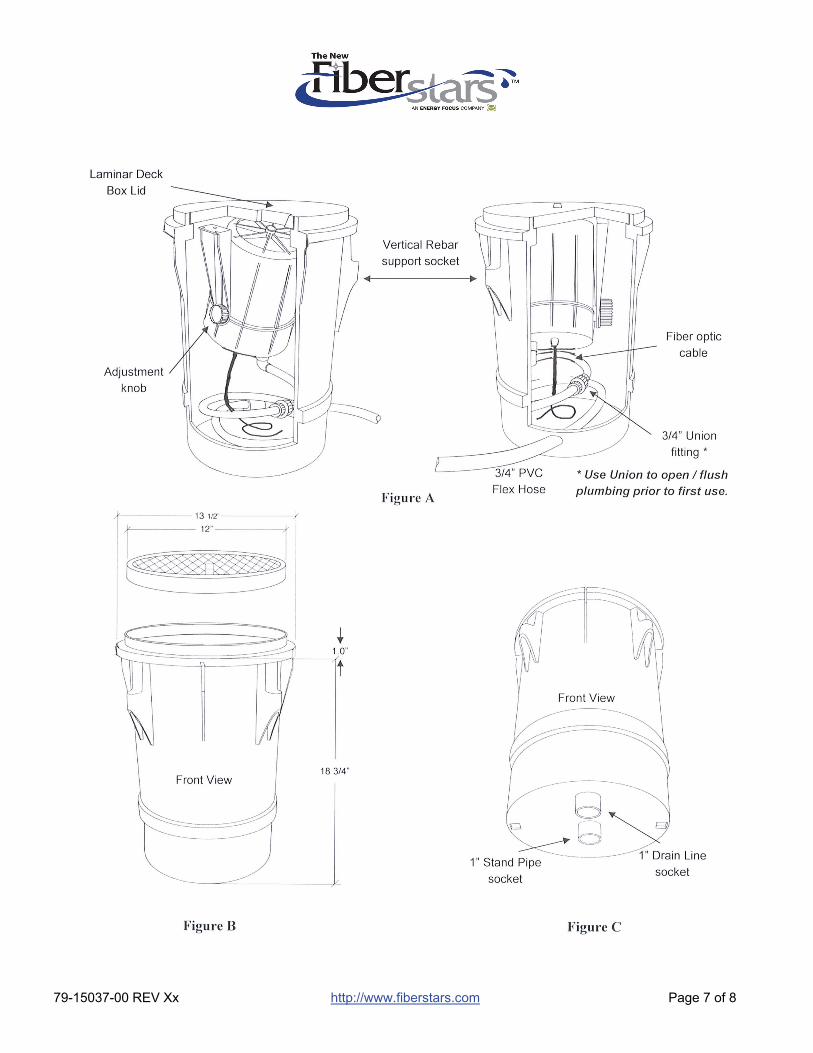
3. Remove the laminar flow fountain from the deck box assembly by unscrewing the hose union connection on the ¾” flex inlet hose. Please note the number of rotations required to wrap the hose inside the deck box and DO NOT shorten the hose.
4. Use the provided union cap on the water line source side of the hose for pressure testing and
winterization. DO NOT LOSE.
5. Place the deck box into the excavated hole on the center stand pipe or rebar sockets on the side of the deck box with the drain line hole in-line with the direction of the desired water flow (towards pool interior). This will place the water connection at the very rear of the Laminar, opposite of the pool wall. Please note that the hose now exits the rear of the deck box at a 45 degree left angle as viewed from the back.
6. The bottom of the deck box can be supported by utilizing the 1” PVC support connection. The support pipe should be long enough to support the deck box at the planned level. You may also support the deck box using the new rebar sockets to help maintain the proper level.
7. Install 1” PVC pipe to the drain line connection. IT IS IMPERATIVE THAT ALL LAMINAR FLOW FOUNTAINS HAVE PROPER DRAINAGE AND ARE NOT ALLOWED TO FLOOD. Failure to provide adequate drainage may prevent proper operation and void warranty.
79-15037-00 REV Xx http://www.fiberstars.com Page 4 of 8
8. Install 1” PVC pipe from deck box to illuminator location (above ground) for fiber optic cable run reduced to ¾” at either side of deck box. It is highly suggested that you install all fiber conduits with sweep fittings for ease of installation.
9. Glue a 1” PVC Water supply line (see table on page 5 for pipe size progression) to the ¾” PVC flex hose water connection using the attached 1” to ¾” reducer.
10. Fill excavated area with gravel until gravel reaches approximately 1” up on bottom of deck box.
11. Finish your deck material installation making sure that the Color Light Streams™ Large
Laminar flow fountains remain level. Utilizing the Adjustable Deck Flange adjust to match your deck height.
IT IS EXTREMELY IMPORTANT THAT THE WATER SUPPLY LINE TO EACH LAMINAR IS
FLUSHED SO THAT ALL MATERIAL THAT MIGHT BE IN THE LINES ARE REMOVED PRIOR TO BEING REINSTALLED INTO THE LAMINAR FLOW DECK BOX. Foreign material and organic
matter will affect the performance of the fountain and is very difficult to remove.
NEVER START UP LAMINAR FOUNTAINS WITHOUT COMPLETING THIS STEP !!
12. After the deck box has been installed and system has been pressure tested using the cap on
the union fitting, the laminar flow fountain itself may be reinstalled.
13. DO NOT REMOVE the clear protective film on the deck box lid until after the pool deck has been installed. This is intended to prevent foreign debris from falling into the jet or deck box and damaging / plugging the unit.
79-15037-00 REV Xx http://www.fiberstars.com Page 5 of 8
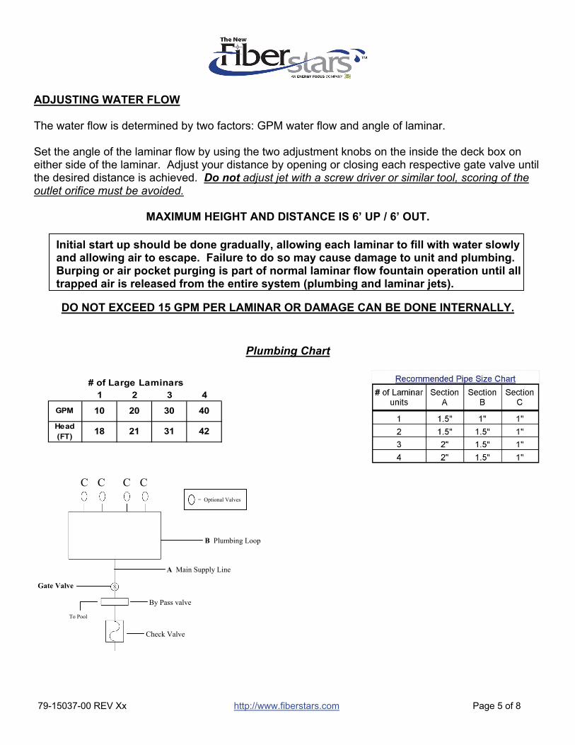
Initial start up should be done gradually, allowing each laminar to fill with water slowly and allowing air to escape. Failure to do so may cause damage to unit and plumbing. Burping or air pocket purging is part of normal laminar flow fountain operation until all trapped air is released from the entire system (plumbing and laminar jets).
1 2 3 4
GPM 10 20 30 40
Head (FT)
18 21 31 42
# of Large Laminars
ADJUSTING WATER FLOW The water flow is determined by two factors: GPM water flow and angle of laminar. Set the angle of the laminar flow by using the two adjustment knobs on the inside the deck box on either side of the laminar. Adjust your distance by opening or closing each respective gate valve until the desired distance is achieved. Do not adjust jet with a screw driver or similar tool, scoring of the outlet orifice must be avoided.
MAXIMUM HEIGHT AND DISTANCE IS 6’ UP / 6’ OUT.
DO NOT EXCEED 15 GPM PER LAMINAR OR DAMAGE CAN BE DONE INTERNALLY.
Plumbing Chart
C C C C
B Plumbing Loop
A Main Supply Line
By Pass valve
Check Valve
To Pool
= Optional Valves
Gate Valve
79-15037-00 REV Xx http://www.fiberstars.com Page 6 of 8
IMPORTANT NOTES AND REMINDERS Always try to leave a minimum of 2’ of fiber on the inside of each laminar flow deck box for servicing. Max fiber runs are 5 feet off fiber distance. This is caused by conduit runs, fittings, etc. 20 feet = 15 feet maximum distance 40 feet = 35 feet maximum distance Fill conduit connection inside of the deck box with silicone or similar material to minimize water from entering fiber conduit. Conduit should be watertight all the way to the illuminator and terminate above grade level. Minimize the number of plumbing fittings in the water run to cut down flow restrictions and water turbulence. When using multiple laminar flow fountains it is extremely important that the fiber optic cables are the same length, regardless if they are different distances from the illuminator. Example: If you have 1 laminar at 20ft and another at 40ft, both should have 40ft of fiber. Laminar flow fountains are susceptible to wind conditions and the higher the angle of your fountain the more they may be effected. If your area has regular amounts of high winds you may consider moving the fountains closer to the pool edge and decreasing the angle of the fountain. For adjustment of Fiberstars Light Enhancement Device (Scratcher) please see attached direction sheet.
Winterization is recommended in areas with freezing conditions.
Winterization steps:
1. Remove fiber optic cable from jet by loosening the compression fitting at the bottom center of the jet body. Gently pull fiber optic cable out of the light tube and loosely coil and place in a plastic bag.
2. Carefully loosen and separate the ¾” union on the water supply line inside the deck box - be careful not to lose any O-ring seals. BLOW WATER LINES CLEAR and use the winterization / pressure test cap to seal the water line.
3. Loosen and remove the adjustment knobs on the side of the jet. Pop the cover caps off being careful to also remove the o-ring seals. Place caps, o-rings, and threaded knobs together in a plastic bag to keep with the jet body once removed for storage.
4. Gently pry one of the mounting arms away from the jet body and roll the jet body out of the mounting arms, the second arm should release easily once the first one is clear.
5. Remove jet body and dump remaining water from it by slowly rotating the jet in all directions – DO NOT DROP. Water will come out of all four openings at different times and positions. Repeat until all water is removed. Store jet bodies and the attachment hardware together in a safe location.
79-15037-00 REV Xx http://www.fiberstars.com Page 7 of 8
79-15037-00 REV Xx http://www.fiberstars.com Page 8 of 8
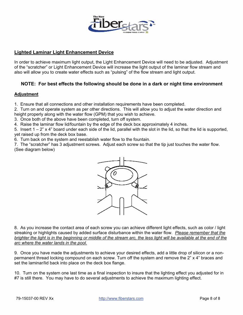
Lighted Laminar Light Enhancement Device
In order to achieve maximum light output, the Light Enhancement Device will need to be adjusted. Adjustment of the “scratcher” or Light Enhancement Device will increase the light output of the laminar flow stream and also will allow you to create water effects such as “pulsing” of the flow stream and light output.
NOTE: For best effects the following should be done in a dark or night time environment
Adjustment 1. Ensure that all connections and other installation requirements have been completed. 2. Turn on and operate system as per other directions. This will allow you to adjust the water direction and height properly along with the water flow (GPM) that you wish to achieve. 3. Once both of the above have been completed, turn off system. 4. Raise the laminar flow lid/fountain by the edge of the deck box approximately 4 inches. 5. Insert 1 – 2” x 4” board under each side of the lid, parallel with the slot in the lid, so that the lid is supported, yet raised up from the deck box base. 6. Turn back on the system and reestablish water flow to the fountain. 7. The “scratcher” has 3 adjustment screws. Adjust each screw so that the tip just touches the water flow. (See diagram below)
8. As you increase the contact area of each screw you can achieve different light effects, such as color / light streaking or highlights caused by added surface disturbance within the water flow. Please remember that the brighter the light is in the beginning or middle of the stream arc, the less light will be available at the end of the arc where the water lands in the pool. 9. Once you have made the adjustments to achieve your desired effects, add a little drop of silicon or a non-permanent thread locking compound on each screw. Turn off the system and remove the 2” x 4” braces and set the laminar/lid back into place on the deck box flange. 10. Turn on the system one last time as a final inspection to insure that the lighting effect you adjusted for in #7 is still there. You may have to do several adjustments to achieve the maximum lighting effect.