fertimix user´s manual fertimix user’s manual - smits bv · fertimix user’s manual ... main...
TRANSCRIPT

Fertimix User’s manual
User’s manual ....................................................................................................................................................................... 2 Fertimix majour parts....................................................................................................................................................... 2 Principle of operation:...................................................................................................................................................... 3
Verbal description:....................................................................................................................................................... 3 Tabular description: ..................................................................................................................................................... 3
Continuouse mode - Principle of operation:................................................................................................................ 3 Detailed description of the components....................................................................................................................... 4
1 . The water meter........................................................................................................................................................ 4 2 . The fill valve ............................................................................................................................................................. 4 8 . A float valve (Item 8) .............................................................................................................................................. 4
Types of valves:............................................................................................................................................................ 4 3 . The mixing tank........................................................................................................................................................ 4 4 . The Mixer pump....................................................................................................................................................... 4 5 . Main irrigation valve ............................................................................................................................................... 4 6 . Manual By-pass........................................................................................................................................................ 5 7 . Water outlet (Fertimix’s downstream) ................................................................................................................ 5 9 . Venturi Fertilizer injectors ..................................................................................................................................... 5
10-11 . EC-pH monitor and probes ............................................................................................................................ 5 12 . Tank level sensor.................................................................................................................................................... 5 13 . Electrical control box ............................................................................................................................................ 5
Technical specifications................................................................................................................................................... 6 Infrastructure requirements: (‘A’ modules are for USA, Mexico and all other 60 Hz network countries).......................................................................................................................................................................................... 6
Operation ............................................................................................................................................................................ 8 Irrigation Setup:............................................................................................................................................................ 8 Mixer Setup:.................................................................................................................................................................. 8 Fertilizer Injectors Adjustment................................................................................................................................10 Fertigation automation setup ...................................................................................................................................10 In most cases it is found that the program’s default values are suitable to all Fertimix models. ..............10 Measure delay at irrigation start – sec. at code 5241# 1 to 20............................10 Change fertigation delay – sce. at code 5241# 2 to 8....................................................... 10 If EC or pH values doesn’t balance you may try to extend the ‘Change fertigation delay’ a few seconds more. Problems of EC/pH balancing are more likely to occur due to a large contradiction between the required fertilizer quantity and the required EC (in EC injectors) or pH (in pH injectors) levels. Secondly likely are problems of electrical interference on the EC-pH unit, and only third would be the ‘Change fertigation delay’ parameter. Contact your local ES authorized technician for further assistance. PC users ...................................................................................................................................................10 PC users........................................................................................................................................................................11
Maintenance.....................................................................................................................................................................11 Maintenance.....................................................................................................................................................................12
Winterizing..................................................................................................................................................................12
1
Fertimix User´s Manual
1
Fertimix User’s manual
Fertimix User’s manual
Eldar-Shany is thanking you for choosing our Fertimix irrigation and fertigation machine. For more then 20 years we do not spare efforts to develop and provide with the best software and hardware solutions for friendly and accurate control of intensive agriculture. We, in Eldar-Shany, have the confidence that using our product by following the instructions of this manual will bring you many years of satisfying results and prosperity with the regarding project. This manual book will guide you through installation, First operation of the machine, Regular operation and maintenance. Note: Fertimix is provided with Galileo controller, and operated by Eldar greenhouse irrigation software. Apart of few concerned paragraphs – Installing and operating the Galileo controller is fully explained in the Gelileo setup manual book, and the operation of the Greenhouse irrigation software is fully explained in the Greenhouse irrigation manual book. You will be directed to those books in the right points. If you use the Galileo PC center you will find all the regarding information in the Galileo PC center manual book. The chapters of this book:
1. Pre-Installation infrastructure recommendations – provided as a separate document prior to the Fertimix shipment.
2. General description (major parts) 3. Place and connect. 4. Description of the mixing procedure. 5. First time operation. 6. Maintenance. 7. Appendix A – layouts. 8. Appendix B – Parts list and ordering information. 9. Appendix C – troubleshooting.
7 5
2
1
3
4
6
13
EC-
Figure 1
10
8
9
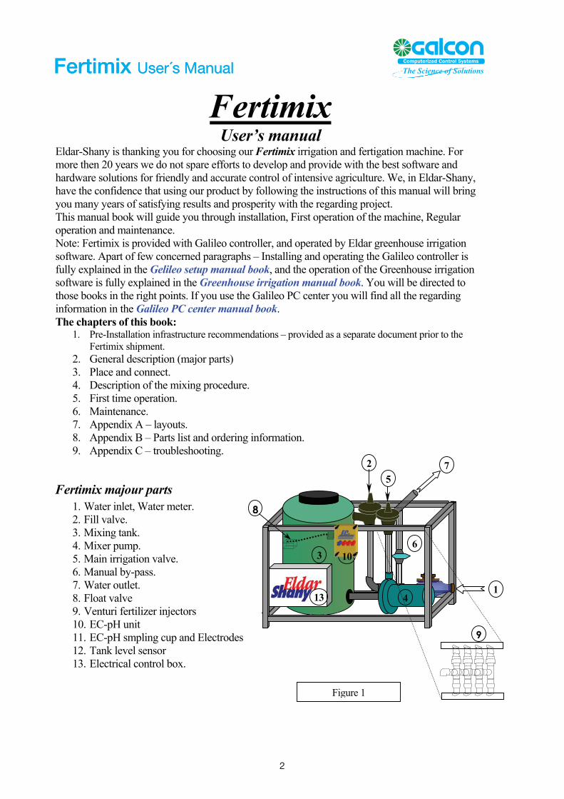
Fertimix majour parts 1. Water inlet, Water meter. 2. Fill valve. 3. Mixing tank. 4. Mixer pump. 5. Main irrigation valve. 6. Manual by-pass. 7. Water outlet. 8. Float valve 9. Venturi fertilizer injectors 10. EC-pH unit 11. EC-pH smpling cup and Electrodes 12. Tank level sensor 13. Electrical control box.
2
Fertimix User´s Manual
2
Fertimix User´s Manual
Fertimix User’s manual
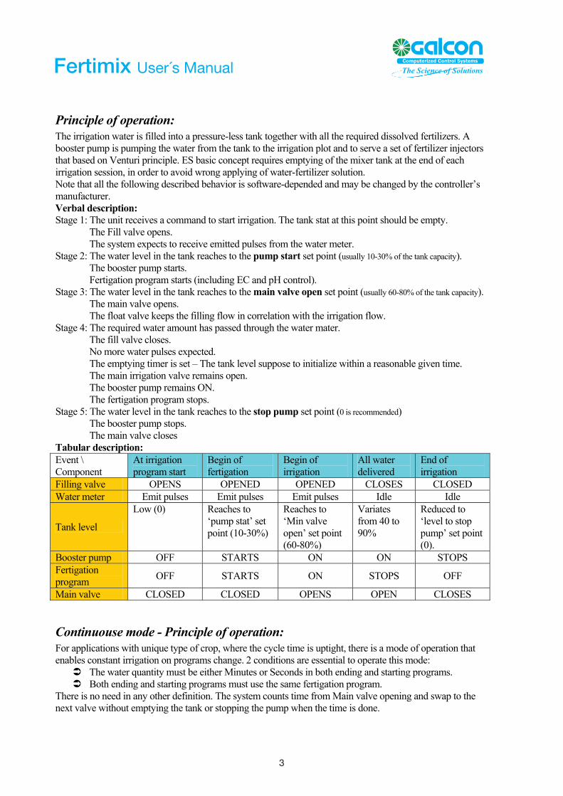
Principle of operation: The irrigation water is filled into a pressure-less tank together with all the required dissolved fertilizers. A booster pump is pumping the water from the tank to the irrigation plot and to serve a set of fertilizer injectors that based on Venturi principle. ES basic concept requires emptying of the mixer tank at the end of each irrigation session, in order to avoid wrong applying of water-fertilizer solution. Note that all the following described behavior is software-depended and may be changed by the controller’s manufacturer. Verbal description: Stage 1: The unit receives a command to start irrigation. The tank stat at this point should be empty. The Fill valve opens. The system expects to receive emitted pulses from the water meter. Stage 2: The water level in the tank reaches to the pump start set point (usually 10-30% of the tank capacity). The booster pump starts. Fertigation program starts (including EC and pH control). Stage 3: The water level in the tank reaches to the main valve open set point (usually 60-80% of the tank capacity). The main valve opens. The float valve keeps the filling flow in correlation with the irrigation flow. Stage 4: The required water amount has passed through the water mater. The fill valve closes. No more water pulses expected. The emptying timer is set – The tank level suppose to initialize within a reasonable given time. The main irrigation valve remains open. The booster pump remains ON. The fertigation program stops. Stage 5: The water level in the tank reaches to the stop pump set point (0 is recommended) The booster pump stops. The main valve closes Tabular description: Event \ Component
At irrigation program start
Begin of fertigation
Begin of irrigation
All water delivered
End of irrigation
Filling valve OPENS OPENED OPENED CLOSES CLOSED Water meter Emit pulses Emit pulses Emit pulses Idle Idle
Tank level
Low (0) Reaches to ‘pump stat’ set point (10-30%)
Reaches to ‘Min valve open’ set point (60-80%)
Variates from 40 to 90%
Reduced to ‘level to stop pump’ set point (0).
Booster pump OFF STARTS ON ON STOPS Fertigation program OFF STARTS ON STOPS OFF
Main valve CLOSED CLOSED OPENS OPEN CLOSES
Continuouse mode - Principle of operation: For applications with unique type of crop, where the cycle time is uptight, there is a mode of operation that enables constant irrigation on programs change. 2 conditions are essential to operate this mode:
The water quantity must be either Minutes or Seconds in both ending and starting programs. Both ending and starting programs must use the same fertigation program.
There is no need in any other definition. The system counts time from Main valve opening and swap to the next valve without emptying the tank or stopping the pump when the time is done.
3 3
Fertimix User´s Manual
Fertimix User’s manual
Detailed description of the components 1. The water meter
The water-meter is rated according to the Fertimix nominal size and its expected flow rate. However, the pulse size may be requested other than the standard one, according to the application optimization.
Model: 1” E 1”A 2”E 2”A 3”E 3”A 3”HFE 3”HFA W. meter type Arad multijet 1” Qn5 Arad multijet 2” Qn15 Bermad WT 3” Bermad WT 3”
Standard pulse size 1 liter 1 gallon 10 liter 1 gallon 10 liter 10 gallon 100 liter 10 gallon See more technical details in appendix A.
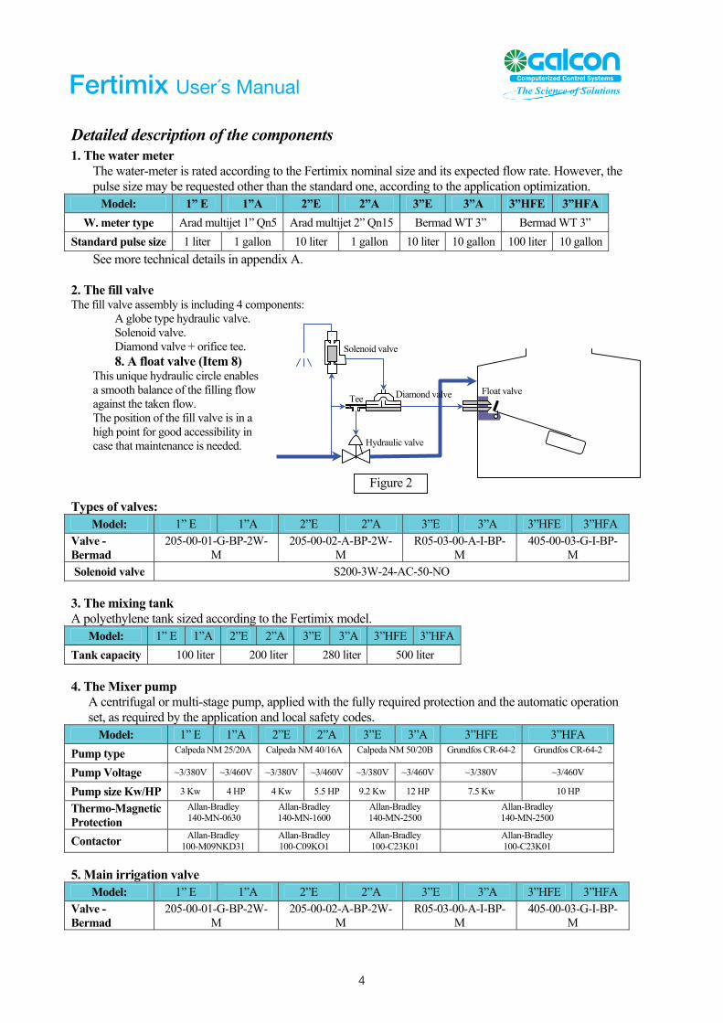
2. The fill valve The fill valve assembly is including 4 components: A globe type hydraulic valve. Solenoid valve.
Figure 2
Tee
Hydraulic valve
Float valve Diamond valve
Solenoid valve Diamond valve + orifice tee. 8. A float valve (Item 8)
This unique hydraulic circle enables a smooth balance of the filling flow against the taken flow. The position of the fill valve is in a high point for good accessibility in case that maintenance is needed.
Types of valves:
Model: 1” E 1”A 2”E 2”A 3”E 3”A 3”HFE 3”HFA Valve - Bermad
205-00-01-G-BP-2W-M
205-00-02-A-BP-2W-M
R05-03-00-A-I-BP-M
405-00-03-G-I-BP-M
Solenoid valve S200-3W-24-AC-50-NO 3. The mixing tank A polyethylene tank sized according to the Fertimix model.
Model: 1” E 1”A 2”E 2”A 3”E 3”A 3”HFE 3”HFA Tank capacity 100 liter 200 liter 280 liter 500 liter 4. The Mixer pump
A centrifugal or multi-stage pump, applied with the fully required protection and the automatic operation set, as required by the application and local safety codes.
Model: 1” E 1”A 2”E 2”A 3”E 3”A 3”HFE 3”HFA Pump type Calpeda NM 25/20A Calpeda NM 40/16A Calpeda NM 50/20B Grundfos CR-64-2 Grundfos CR-64-2
Pump Voltage ~3/380V ~3/460V ~3/380V ~3/460V ~3/380V ~3/460V ~3/380V ~3/460V
Pump size Kw/HP 3 Kw 4 HP 4 Kw 5.5 HP 9.2 Kw 12 HP 7.5 Kw 10 HP
Thermo-Magnetic Protection
Allan-Bradley 140-MN-0630
Allan-Bradley 140-MN-1600
Allan-Bradley 140-MN-2500
Allan-Bradley 140-MN-2500
Contactor Allan-Bradley 100-M09NKD31
Allan-Bradley 100-C09KO1
Allan-Bradley 100-C23K01
Allan-Bradley 100-C23K01
5. Main irrigation valve
Model: 1” E 1”A 2”E 2”A 3”E 3”A 3”HFE 3”HFA Valve - Bermad
205-00-01-G-BP-2W-M
205-00-02-A-BP-2W-M
R05-03-00-A-I-BP-M
405-00-03-G-I-BP-M
4 4
Fertimix User´s Manual
Fertimix User’s manual
6. Manual By-pass The manual by-pass is a PVC ball/butterfly valve that needs to be opened only in case of total controller failure. Opening the by-pass valve is practically disabling the entire machine functionality. When the by-pass valve is opened – the main valve (5) must be manually closed to avoid water back-leak to the tank and out.
7. Water outlet (Fertimix’s downstream)
Where the irrigation system should be connected. Notice that no check valve or secondary filtration is provided with the Fertimix.
Model: 1” E 1”A 2”E 2”A 3”E 3”A 3”HFE 3”HFA Outlet connection
Tread 1” BSP
Tread 1” MNPT
Tread 2” BSP
Flange 2” ANSI
Flange 75mm BS
Flange 3” ANSI
100 liter
10 gallon
9. Venturi Fertilizer injectors
See appendix B below.
10-11. EC-pH monitor and probes
Figure 3
Air inlet
ZEROGAIN
See associated EC-pH manual. 12. Tank level sensor
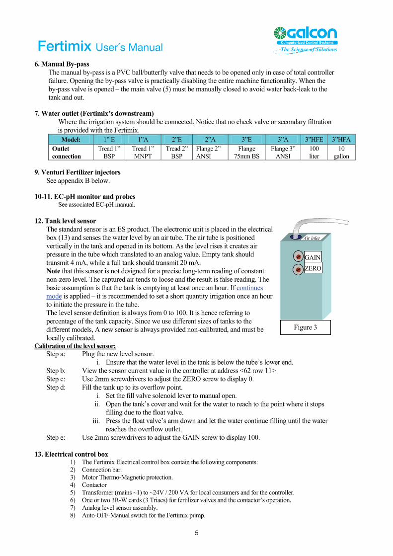
The standard sensor is an ES product. The electronic unit is placed in the electrical box (13) and senses the water level by an air tube. The air tube is positioned vertically in the tank and opened in its bottom. As the level rises it creates air pressure in the tube which translated to an analog value. Empty tank should transmit 4 mA, while a full tank should transmit 20 mA. Note that this sensor is not designed for a precise long-term reading of constant non-zero level. The captured air tends to loose and the result is false reading. The basic assumption is that the tank is emptying at least once an hour. If continues mode is applied – it is recommended to set a short quantity irrigation once an hour to initiate the pressure in the tube. The level sensor definition is always from 0 to 100. It is hence referring to percentage of the tank capacity. Since we use different sizes of tanks to the different models, A new sensor is always provided non-calibrated, and must be locally calibrated.
Calibration of the level sensor: Step a: Plug the new level sensor.
i. Ensure that the water level in the tank is below the tube’s lower end. Step b: View the sensor current value in the controller at address <62 row 11> Step c: Use 2mm screwdrivers to adjust the ZERO screw to display 0. Step d: Fill the tank up to its overflow point.
i. Set the fill valve solenoid lever to manual open. ii. Open the tank’s cover and wait for the water to reach to the point where it stops
filling due to the float valve. iii. Press the float valve’s arm down and let the water continue filling until the water
reaches the overflow outlet. Step e: Use 2mm screwdrivers to adjust the GAIN screw to display 100.
13. Electrical control box 1) The Fertimix Electrical control box contain the following components: 2) Connection bar. 3) Motor Thermo-Magnetic protection. 4) Contactor 5) Transformer (mains ~1) to ~24V / 200 VA for local consumers and for the controller. 6) One or two 3R-W cards (3 Triacs) for fertilizer valves and the contactor’s operation. 7) Analog level sensor assembly. 8) Auto-OFF-Manual switch for the Fertimix pump.
5 5
Fertimix User´s Manual
Fertimix User’s manual
9) A 6A protective switch for the ~1 mains. 10) See appendix D for detailed layout
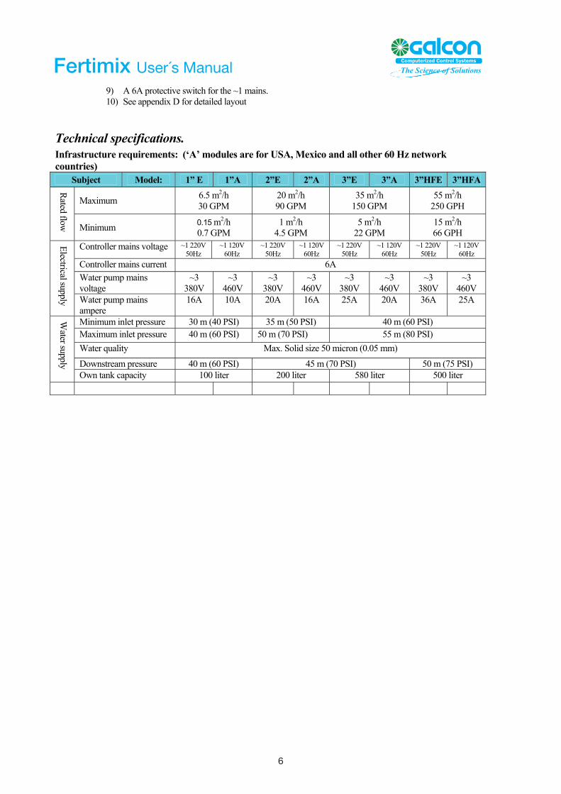
Technical specifications. Infrastructure requirements: (‘A’ modules are for USA, Mexico and all other 60 Hz network countries)
Subject Model: 1” E 1”A 2”E 2”A 3”E 3”A 3”HFE 3”HFA
Maximum 6.5 m2/h 30 GPM
20 m2/h 90 GPM
35 m2/h 150 GPM
55 m2/h 250 GPH
Rated flow Minimum 0.15 m2/h
0.7 GPM 1 m2/h
4.5 GPM 5 m2/h
22 GPM 15 m2/h 66 GPH
Controller mains voltage ~1 220V 50Hz
~1 120V 60Hz
~1 220V 50Hz
~1 120V 60Hz
~1 220V 50Hz
~1 120V 60Hz
~1 220V 50Hz
~1 120V 60Hz
Controller mains current 6A Wvo
ater pump mains ltage
~3 380V
~3 460V
~3 380V
~3 460V
~3 380V
~3 460V
~3 380V
~3 460V
Electrical supply Water pump mains ampere
16A 10A 20A 16A 25A 20A 36A 25A
Minimum inlet pressure 30 m (40 PSI) 35 m (50 PSI) 40 m (60 PSI) Maximum inlet pressure 40 m (60 PSI) 50 m (70 PSI) 55 m (80 PSI) Water quality Max. Solid size 50 micron (0.05 mm)
Downstream pressure 40 m (60 PSI) 45 m (70 PSI) 50 m (75 PSI)
Water supply
Own tank capacity 100 liter 200 liter 580 liter 500 liter
6 6
Fertimix User´s Manual
Fertimix User’s manual
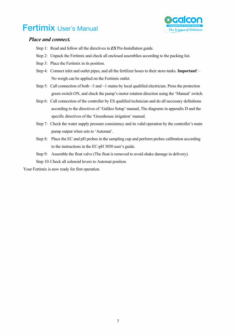
Place and connect. Step 1: Read and follow all the directives in ES Pre-Installation guide.
Step 2: Unpack the Fertimix and check all enclosed assemblies according to the packing list.
Step 3: Place the Fertimix in its position.
Step 4: Connect inlet and outlet pipes, and all the fertilizer hoses to their store-tanks. Important! –
No weigh can be applied on the Fertimix outlet.
Step 5: Call connection of both ~3 and ~1 mains by local qualified electrician. Press the protection
green switch ON, and check the pump’s motor rotation direction using the ‘Manual’ switch.
Step 6: Call connection of the controller by ES qualified technician and do all necessary definitions
according to the directives of ‘Galileo Setup’ manual, The diagrams in appendix D and the
specific directives of the ‘Greenhouse irrigation’ manual.
Step 7: Check the water supply pressure consistency and its valid operation by the controller’s main
pump output when sets to ‘Automat’.
Step 8: Place the EC and pH probes in the sampling cup and perform probes calibration according
to the instructions in the EC-pH 3050 user’s guide.
Step 9: Assemble the float valve (The float is removed to avoid shake damage in delivery).
Step 10: Check all solenoid levers to Automat position.
Your Fertimix is now ready for first operation.
7 7
Fertimix User´s Manual
Fertimix User’s manual
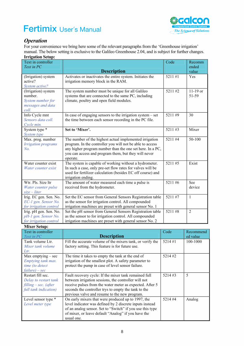
Operation For your convenience we bring here some of the relevant paragraphs from the ‘Greenhouse irrigation’ manual. The below setting is exclusive to the Galileo Greenhouse 2.04, and is subject for further changes. Irrigation Setup: Text in controller Text in PC
Description
Code Recommended value
(Irrigation) system active? System active?
Activates or inactivates the entire system. Initiates the irrigation memory block in the RAM.
5211 #1 Yes
(Irrigation) system number. System number for messages and data coll.
The system number must be unique for all Galileo systems that are connected to the same PC, including climate, poultry and open field modules.
5211 #2 11-19 or 51-59
Info Cycle mnt Sensors data coll. Cycle min.
In case of engaging sensors to the irrigation system – set the time between each sensor recording in the PC file.
5211 #9 30
System type * System type
Set to ‘Mixer’. 5211 #3 Mixer
Max. prog. number Irrigation programs No.
The number of the highest actual implemented irrigation program. In the controller you will not be able to access any higher program number than the one set here. In a PC, you can access and program them, but they will never operate.
5211 #4 50-100
Water counter exist Water counter exist
The system is capable of working without a hydrometer. In such a case, only pre-set flow rates for valves will be used for fertilizer calculation (besides EC off course) and irrigation ending.
5211 #5 Exist
Wtr. Pls. Size ltr Water counter pulse size – liter
The amount of water measured each time a pulse is received from the hydrometer.
5211 #6 See device
Irig. EC gen. Sen. No. EC-1 gen. Sensor No. for irrigation control
Set the EC sensor from General Sensors Registration table as the sensor for irrigation control. All compounded irrigation machines are preset with general sensor No. 1
5211 #7 1
Irig. pH gen. Sen. No. pH-1 gen. Sensor No. for irrigation control
Set the pH sensor from General Sensors Registration table as the sensor to for irrigation control. All compounded irrigation machines are preset with general sensor No. 2
5211 #8 2
Mixer Setup: Text in controller Text in PC Description
Code Recommended value
Tank volume Ltr. Mixer tank volume Ltr.
Fill the accurate volume of the mixers tank, or verify the factory setting. This feature is for future use.
5214 #1 100-1000
Max emptying – sec Emptying tank max. time (to detect failure) – sec
The time it takes to empty the tank at the end of irrigation of the smallest plot. A safety parameter to protect the pump in case of level sensor failure.
5214 #2
Restart fill sec. Delay to restart tank filling – sec. (after full tank indication)
Fault recovery cycle: If the mixer tank remained full between irrigation sessions, the controller will not receive pulses from the water meter as expected. After 5 seconds the controller trys to empty the tank to the previous valve and resume to the new program.
5214 #3 5
Level sensor type * Level meter type
On early mixers that were produced up to 1997, the level indicator was defined by 2 discrete inputs instead of an analog sensor. Set to “Switch” if you use this type of mixer, or leave default “Analog” if you have the usual one.
5214 #4 Analog
8 8
Fertimix User´s Manual
Fertimix User’s manual
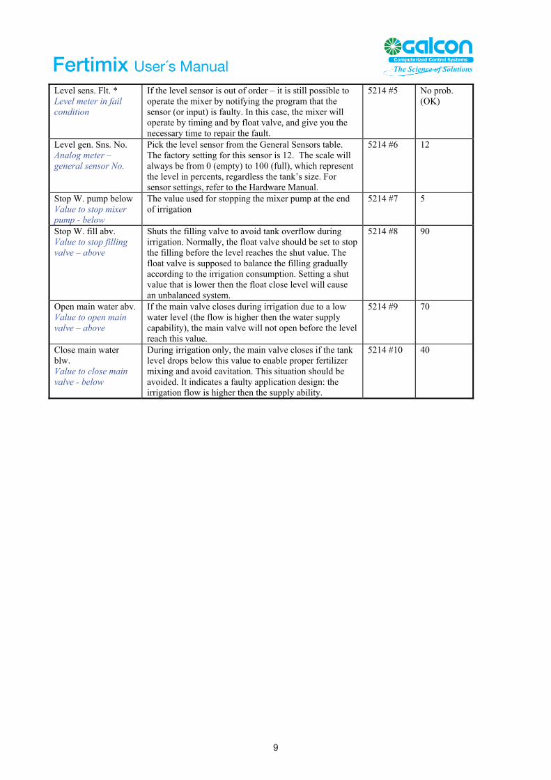
Level sens. Flt. * Level meter in fail condition
If the level sensor is out of order – it is still possible to operate the mixer by notifying the program that the sensor (or input) is faulty. In this case, the mixer will operate by timing and by float valve, and give you the necessary time to repair the fault.
5214 #5 No prob. (OK)
Level gen. Sns. No. Analog meter – general sensor No.
Pick the level sensor from the General Sensors table. The factory setting for this sensor is 12. The scale will always be from 0 (empty) to 100 (full), which represent the level in percents, regardless the tank’s size. For sensor settings, refer to the Hardware Manual.
5214 #6 12
Stop W. pump below Value to stop mixer pump - below
The value used for stopping the mixer pump at the end of irrigation
5214 #7 5
Stop W. fill abv. Value to stop filling valve – above
Shuts the filling valve to avoid tank overflow during irrigation. Normally, the float valve should be set to stop the filling before the level reaches the shut value. The float valve is supposed to balance the filling gradually according to the irrigation consumption. Setting a shut value that is lower then the float close level will cause an unbalanced system.
5214 #8 90
Open main water abv. Value to open main valve – above
If the main valve closes during irrigation due to a low water level (the flow is higher then the water supply capability), the main valve will not open before the level reach this value.
5214 #9 70
Close main water blw. Value to close main valve - below
During irrigation only, the main valve closes if the tank level drops below this value to enable proper fertilizer mixing and avoid cavitation. This situation should be avoided. It indicates a faulty application design: the irrigation flow is higher then the supply ability.
5214 #10 40
9 9
Fertimix User´s Manual

Fertimix User’s manual
Fertilizer Injectors Adjustment Every fertilizer injector must be flow- adjusted to some extent. To adjust, use one of three methods as listed below: Fixed cone-jets of 20, 40, 60 and 80 liter/hour (5, 10, 15 and 20 GPM). Flow- control valve. Flow indicator with control valve. Follow the instructions in the table below as applicable to the method selected for each injector:
Step Cone-jet Adjustable valve Flow indicator
1 Calculate optimal pump flow to inject during 40-70% of the irrigation time, taking into consideration the specific mainline flow, fertilizer concentration and final quantity of nutrient required. Consult ftp://ftp.eldarshany.com/pub/literature/Fert_Calc.xls (“Fert Calc” sheet) as required.
2 Fit jet in housing Remove bottom cover of fertilizer solenoid valve by unscrewing the 2 flat bolts. 3 Immerse the far end of the flexible pipe in a measurable
bucket of water. Start the irrigation program.
Immerse the far end of the flexible pipe in a bucket of water. Start the irrigation program.
4 Operate a normal irrigation with no fertigation program. Use a valve with no crop or a kind of list sensitive crop.
5 Press the solenoid’s plunger up with your finger for exactly 30 seconds.
Press the solenoid’s plunger up with your finger and set the required flow on the scale.
6 Measure the amount of water pumped out of the bucket. Calculate the flow by multiplying the quantity of the missing water by 120.
Fit the plunger protector back in place and secure with bolts.
7 Adjust the valve slightly. Repeat steps 4-5 until the required flow is obtained. Fit the plunger protector back in place and secure with bolts.
8 Update the “Fertilizer pump flow” parameter in the controller: code <5216 #3> in CL_IR 2.04 or code <452 #3> Fertigation automation setup
In most cases it is found that the program’s default values are suitable to all Fertimix models. Measure delay at irrigation start – sec. at code 5241 #1 to 20
Change fertigation delay – sce. at code 5241 #2 to 8 If EC or pH values doesn’t balance you may try to extend the ‘Change fertigation delay’ a few seconds more. Problems of EC/pH balancing are more likely to occur due to a large contradiction between the required fertilizer quantity and the required EC (in EC injectors) or pH (in pH injectors) levels. Secondly likely are problems of electrical interference on the EC-pH unit, and only third would be the ‘Change fertigation delay’ parameter. Contact your local ES authorized technician for further assistance.
10 10
Fertimix User´s Manual

Fertimix User’s manual
PC users To appropriately operate Fertimix from the Galileo PC center, you must enter the
system by clicking the “Ometz” button. If you click any of the two others – the
operation of your system will not be effected, but you won’t be able to see all the
specific mixer’s visualization properties.
Ometz is the former name of this product.
The System Setup dialog box can be found in the top menu item ‘Settings’ >
‘Irrigation settings’ > ‘System setup’. The special m
settings are in ‘Settings’ > ‘Irrigation settings’ >
‘Mixer’.
ixer
Figure 4
11
11
Fertimix User´s Manual
Fertimix User’s manual
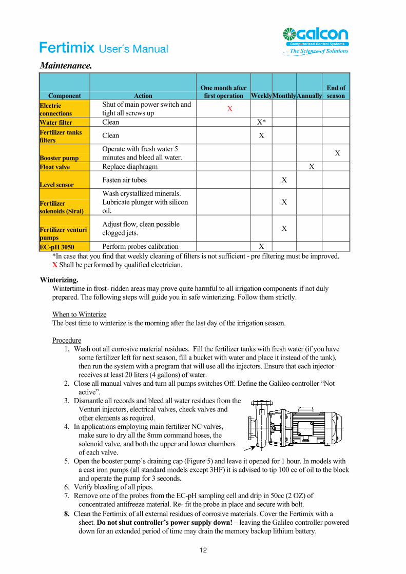
Maintenance.
Component Action One month after first operation WeeklyMonthly Annually
End of season
Electric connections
Shut of main power switch and tight all screws up X
Water filter Clean X* Fertilizer tanks filters
Clean X
Booster pump Operate with fresh water 5 minutes and bleed all water. X
Float valve Replace diaphragm X
Level sensor Fasten air tubes X
Fertilizer solenoids (Sirai)
Wash crystallized minerals. Lubricate plunger with silicon oil.
X
Fertilizer venturi pumps
Adjust flow, clean possible clogged jets. X
EC-pH 3050 Perform probes calibration X *In case that you find that weekly cleaning of filters is not sufficient - pre filtering must be improved. X Shall be performed by qualified electrician.
Winterizing.
Wintertime in frost- ridden areas may prove quite harmful to all irrigation components if not duly prepared. The following steps will guide you in safe winterizing. Follow them strictly. When to Winterize The best time to winterize is the morning after the last day of the irrigation season. Procedure
1. Wash out all corrosive material residues. Fill the fertilizer tanks with fresh water (if you have some fertilizer left for next season, fill a bucket with water and place it instead of the tank), then run the system with a program that will use all the injectors. Ensure that each injector receives at least 20 liters (4 gallons) of water.
2. Close all manual valves and turn all pumps switches Off. Define the Galileo controller “Not active”.
3. Dismantle all records and bleed all water residues from the Venturi injectors, electrical valves, check valves and other elements as required.
4. In applications employing main fertilizer NC valves, make sure to dry all the 8mm command hoses, the solenoid valve, and both the upper and lower chambers of each valve.
5. Open the booster pump’s draining cap (Figure 5) and leave it opened for 1 hour. In models with a cast iron pumps (all standard models except 3HF) it is advised to tip 100 cc of oil to the block and operate the pump for 3 seconds.
6. Verify bleeding of all pipes. 7. Remove one of the probes from the EC-pH sampling cell and drip in 50cc (2 OZ) of
concentrated antifreeze material. Re- fit the probe in place and secure with bolt.
12
Fertimix User’s manual
Maintenance.
Component Action One month after first operation WeeklyMonthly Annually
End of season
Electric connections
Shut of main power switch and tight all screws up X
Water filter Clean X* Fertilizer tanks filters
Clean X
Booster pump Operate with fresh water 5 minutes and bleed all water. X
Float valve Replace diaphragm X
Level sensor Fasten air tubes X
Fertilizer solenoids (Sirai)
Wash crystallized minerals. Lubricate plunger with silicon oil.
X
Fertilizer venturi pumps
Adjust flow, clean possible clogged jets. X
EC-pH 3050 Perform probes calibration X *In case that you find that weekly cleaning of filters is not sufficient - pre filtering must be improved. X Shall be performed by qualified electrician.
Winterizing.
Wintertime in frost- ridden areas may prove quite harmful to all irrigation components if not duly prepared. The following steps will guide you in safe winterizing. Follow them strictly. When to Winterize The best time to winterize is the morning after the last day of the irrigation season. Procedure
1. Wash out all corrosive material residues. Fill the fertilizer tanks with fresh water (if you have some fertilizer left for next season, fill a bucket with water and place it instead of the tank), then run the system with a program that will use all the injectors. Ensure that each injector receives at least 20 liters (4 gallons) of water.
2. Close all manual valves and turn all pumps switches Off. Define the Galileo controller “Not active”.
3. Dismantle all records and bleed all water residues from the Venturi injectors, electrical valves, check valves and other elements as required.
4. In applications employing main fertilizer NC valves, make sure to dry all the 8mm command hoses, the solenoid valve, and both the upper and lower chambers of each valve.
5. Open the booster pump’s draining cap (Figure 5) and leave it opened for 1 hour. In models with a cast iron pumps (all standard models except 3HF) it is advised to tip 100 cc of oil to the block and operate the pump for 3 seconds.
6. Verify bleeding of all pipes. 7. Remove one of the probes from the EC-pH sampling cell and drip in 50cc (2 OZ) of
concentrated antifreeze material. Re- fit the probe in place and secure with bolt.
12
12
Fertimix User’s manual
8. Clean the Fertimix of all external residues of corrosive materials. Cover the Fertimix with a sheet. Do not shut controller’s power supply down! – leaving the Galileo controller powered down for an extended period of time may drain the memory backup lithium battery.
13
Fertimix User´s Manual