ferris operator’s manualdl.owneriq.net/f/fd10d42f-b794-4f44-bfba-845fb1918886.pdfdds48 48” mower...
TRANSCRIPT

22880
Rev. 01/2002TP 100-7056-00-WD-F
OPERATOR’SMANUAL
Ferris Industries5375 North Main StreetMunnsville, NY 13409800-933-6175
HydroWalk SeriesDual Drive Walk-Behind Mowers
PowerheadsModel Number: Description:DDSKAV15 Dual Drive w/ 15HP KawasakiDDSKAV15CE Dual Drive w/ 15HP Kawasaki (Export)DDSKAV17 Dual Drive w/ 17HP KawasakiDDSKAV17CE Dual Drive w/ 17HP Kawasaki (Export)DDSKAV23 Dual Drive w/ 23HP KawasakiDDSKAV23CE Dual Drive w/ 23HP Kawasaki (Export)
FERRIS
48” Mower DecksModel Number: Description:DDS48 48” Mower DeckDDS48R 48” Rear Discharge Mower Deck (Export)
61” Mower DecksModel Number: Description:DDS61 61” Mower DeckDDSH61 61” E-Z Adjust Mower Deck
52” Mower DecksModel Number: Description:DDS52 52” Mower DeckDDS52R 52” Rear Discharge Mower Deck (Export)DDSH52 52” E-Z Adjust Mower Deck

Ferris Industries5375 North Main StreetMunnsville, NY 13409800-933-6175
www.ferrisindustries.com
© Copyright 2002 Ferris IndustriesAll Rights Reserved. Printed in USA.
FERRIS
FERRIS LIMITED WARRANTY
IMPORTANTThis warranty shall apply ONLY if the warranty registration form has been completed andreturned to Ferris Industries, Inc. within 20 days from the date of delivery.
Ferris Industries, Inc. (Ferris) warrants, in accordance with the provisions below, to theoriginal purchaser for the period of twenty-four (24) months from the date of delivery of aFerris mower that the mower is free from defects in material or workmanship. Ferris’ obli-gation under this warranty is to repair or replace, at Ferris’ election, without charge and atthe place of business of a dealer authorized to handle Ferris mowers, any part or parts ofthe machine which, in the judgment of Ferris, prove to be defective.
THIS WARRANTY AND FERRIS’ OBLIGATION HEREUNDER IS IN LIEU OF ALL OTHERWARRANTIES, EXPRESSED OR IMPLIED, INCLUDING, WITHOUT LIMITATION, THEIMPLIED WARRANTY OF MERCHANTABILITY OR IMPLIED WARRANTY OF FITNESSFOR PARTICULAR PURPOSE, and all other obligations or liabilities of Ferris for incidentaland consequential damages resulting from the design, manufacture, sale or use of themachine. No person is authorized to make any warranty or assume for Ferris any liabilitynot strictly in accordance with this warranty.
This warranty shall not apply to any mower part which, in the judgment of Ferris, has beenaltered or tampered with in any way or has been subjected to misuse, neglect or accident,or has had the serial numbers altered, effaced or removed. This warranty does not applyto component parts not manufactured by Ferris (motors, batteries, tires, belts) except tothe extent of their individual manufacturer’s guarantees.
Ferris Industries, Inc. is continually striving to improve its products, and therefore reservesthe right to make improvements or change when it becomes practical and possible to doso, without incurring any obligation to make changes or additions to the equipment soldpreviously.
1
Table of Contents
WARNINGEngine exhaust from this product containschemicals known, in certain quantities, to causecancer, birth defects, or other reproductive harm.
© Copyright 2002 Ferris IndustriesAll Rights Reserved. Printed in USA.
TP 100-7056-00-WD-F
Identification Tags ...............................................2Safety Rules & Information
Training....................................................................3Preparation..............................................................3Operation ................................................................4Slope Operation ......................................................4Children...................................................................5Emissions................................................................5Maintenance and Storage.......................................5Decals .....................................................................6CE Compliance Specs............................................7
Features & ControlsControl Functions....................................................8Safety Interlock System ..........................................9
Operating the Dual Drive Walk-BehindGeneral Operating Safety .....................................10Checks Before Starting .........................................10Starting the Engine ...............................................11Stopping the Mower ..............................................11Driving the Mower .................................................11Mowing..................................................................12Pushing the Mower by Hand.................................12Storage..................................................................13Starting After Long Term Storage .........................13
Regular MaintenanceMaintenance Schedule .........................................14Checking Tire Pressures.......................................14Checking/Adding Fuel ...........................................15Fuel Filter ..............................................................15Oil & Filter Change ...............................................15Check / Change Air FIlter .....................................15Check Hydraulic Oil Level .....................................15Lubrication ............................................................16Battery Maintenance.............................................17
Checking Battery Fluid ......................................17Cleaning the Battery and Cables.......................17
Servicing the Mower Blades .................................18
Troubleshooting, Adjustments & ServiceTroubleshooting the Mower...................................19Troubleshooting the Mower Deck..........................20Mowing Height Adjustment ...................................21Deck Leveling Adjustment (DDSH models) ..........22Mowing Height Adjustment (DDSH models).........23Mower Belt Replacement......................................24Mower Belt Replacement (DDSH models) ...........25Transmission Drive Belt Replacement ..................26Transmission Neutral & Tracking Adjustments ......27
Neutral Adjustment ............................................27Tracking Adjustment...........................................27
Transmission Maintenance & Service...................28Changing Oil & Filters .......................................28
PTO Clutch Adjustment ........................................29Battery Service .....................................................30
Checking the Battery Voltage ............................30Charging A Completely Discharged Battery......30Jump Starting with
Auxiliary (Booster) Battery .............................30
Replacement Parts & Accessories ..................32
Lawn Care & Mowing Information ...............LC-1
International Symbols...................................LC-8Technical Manuals.........................................LC-8
NOTE: In this manual, “left” and “right” are referred to asseen from the operating position.
WARNINGYou must read, understand and comply with all safetyand operating instructions in this manual beforeattempting to set-up and operate your machine.
Failure to comply with all safety and operatinginstructions can result in loss of machine control,serious personal injury to you and / or bystanders,and risk of equipment and property damage. Thetriangle in the text signifies important cautions orwarnings which must be followed.
2
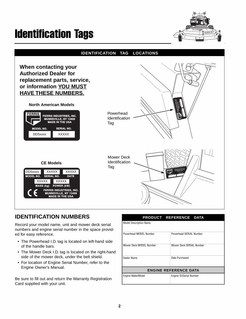
IDENTIFICATION TAG LOCATIONS
Identification Tags
When contacting yourAuthorized Dealer forreplacement parts, service,or information YOU MUSTHAVE THESE NUMBERS.
IDENTIFICATION NUMBERSRecord your model name, unit and mower deck serialnumbers and engine serial number in the space provid-ed for easy reference.
• The Powerhead I.D. tag is located on left-hand sideof the handle bars.
• The Mower Deck I.D. tag is located on the right-handside of the mower deck, under the belt shield.
• For location of Engine Serial Number, refer to theEngine Owner’s Manual.
Be sure to fill out and return the Warranty RegistrationCard supplied with your unit.
ENGINE REFERENCE DATA
Model Description Name
Powerhead MODEL Number
PRODUCT REFERENCE DATA
Powerhead SERIAL Number
Dealer Name Date Purchased
Engine Make/Model Engine ID/Serial Number
Mower Deck MODEL Number Mower Deck SERIAL Number
MODEL NO.MODEL NO. SERIAL NO.SERIAL NO.
FERRIS INDUSTRIES, INC.FERRIS INDUSTRIES, INC.MUNNSVILLE, NY 13409 MUNNSVILLE, NY 13409
MADE IN THE USAMADE IN THE USA
FERRISFERRIS
MODEL NO.MODEL NO. SERIAL NO.SERIAL NO.
FERRIS INDUSTRIES, INC.FERRIS INDUSTRIES, INC.MUNNSVILLE, NY 13409 MUNNSVILLE, NY 13409
MADE IN THE USAMADE IN THE USA
DATEDATE
MASS (kg)MASS (kg) POWER (kW)POWER (kW)
XXXXX XXXXX
XXXXX XXXXX
XXXXX
DDSxxxx
DDSxxxx
North American Models
CE Models
PowerheadIdentificationTag
Mower DeckIdentificationTag
3
Read these safety rules and follow them closely. Failure to obey these rules could result in loss of con-trol of unit, severe personal injury or death to you, or bystanders, or damage to property or equipment.This mowing deck is capable of amputating hands and feet and throwing objects. The triangle intext signifies important cautions or warnings which must be followed.
Safety Rules& Information
TRAINING• Read, understand, and follow all instructions in the
manual and on the unit before starting. If the opera-tor(s) or mechanic(s) can not read English it is theowner’s responsibility to explain this material to them.
• Become familiar with the safe operation of the equip-ment, operator controls, and safety signs.
• All operators and mechanics should be trained. Theowner is responsible for training the users.
• Only allow responsible adults, who are familiar withthe instructions, to operate the unit.
• Never let children or untrained people operate orservice the equipment. Local regulations mayrestrict the age of the operator.
• The owner/user can prevent and is responsible foraccidents or injuries occurring to themselves, otherpeople or property.
• Data indicates that operators, age 60 years andabove, are involved in a large percentage of ridingmower-related injuries. These operators should eval-uate their ability to operate the riding mower safelyenough to protect themselves and others from seri-ous injury.
PREPARATION• Evaluate the terrain to determine what accessories
and attachments are needed to properly and safelyperform the job. Use only accessories and attach-ments approved by the manufacturer.
• Wear appropriate clothing including safety shoes,safety glasses and ear protection. Long hair, looseclothing or jewelry may get tangled in moving parts.
• Inspect the area where the equipment is to be usedand remove all objects such as rocks, toys and wire,which can be thrown by the machine.
• Use extra care when handling gasoline and otherfuels. They are flammable and vapors are explosive.a) Use only an approved container.
b) Never remove fuel cap or add fuel with the enginerunning. Allow engine to cool before refueling. Donot smoke.
c) Never refuel or drain the machine indoors.
• Check that operator’s presence controls, safetyswitches and shields are attached and functioningproperly. Do not operate unless they are functioningproperly.
Safety Rules & Information
OPERATION• Never run an engine in an enclosed area.• Mow only in the daylight or with good artificial light,
keeping away from holes and hidden hazards.• Be sure all drives are in neutral and parking brake is
engaged before starting engine. Only start enginefrom the operator’s position. Use seat belts if provid-ed.
• Be sure of your footing while using pedestrian con-trolled equipment, especially when backing up. Walk,don't run.
• Do not mow in reverse unless absolutely necessary.Always look down and behind before and while trav-eling in reverse.
• Be aware of the mower discharge direction and donot point it at anyone. Do not operate the mowerwithout either the entire grass catcher or the deflec-tor in place.
• Slow down and use caution when making turns andwhen changing directions on slopes.
• Never raise deck with the blades running.• Never leave a running unit unattended. Always disen-
gage the PTO, set parking brake, stop engine, andremove keys before dismounting. Keep hands andfeet away from the cutting units.
• Turn off the PTO switch to disengage the bladeswhen not mowing.
• Never operate with guards not securely in place. Besure all interlocks are attached, adjusted properlyand functioning properly.
• Never operate with the discharge deflector raised,removed or altered, unless using a grass catcher.
• Do not change the engine governor setting or over-speed the engine.
• Stop on level ground, lower implements, disengagedrives, engage parking brake, shut off engine beforeleaving the operator’s position for any reason includ-ing emptying the grass catchers or unclogging thechute.
• Stop equipment and inspect blades after strikingobjects or abnormal vibration occurs. Make neces-sary repairs before resuming operations.
• Keep hands and feet away from the cutting units.• Never carry passengers and keep pets and
bystanders away.• Do not operate the unit while under the influence of
alcohol or drugs.• Slow down and use caution when making turns and
crossing roads and sidewalks. Stop blades if notmowing.
• Use care when loading or unloading the machineinto a trailer or truck.
• Use care when approaching blind corners, shrubs,trees or other objects that may obscure vision.
SLOPE OPERATION
Slopes are a major factor related to loss-of-control and tip-over accidents, which can result in severe injury or death.All slopes require extra caution. If you cannot back up theslope or if you feel uneasy on it, do not drive on it.
Do• Mow across the face of slopes; never up and down.• Remove obstacles such as rocks, tree limbs, etc.• Watch for holes, ruts, or bumps. Uneven terrain
could overturn the unit. Tall grass can hide obsta-cles.
• Use slow speed. Choose a slow speed so that youwill not have to stop or change speed while on theslope.
• Use extra care with grass catchers or other attach-ments. These can change the stability of the unit.
• Keep all movement on the slopes slow and gradual.Do not make sudden changes in speed or direction.
• See your authorized dealer for recommendations ofavailable weights to improve stability.
WARNINGNever operate on slopes greater than 20°(36.4 percent) which is a rise of 7-1/4 feet (220 cm)vertically in 20 feet (607 cm) horizontally.
Select slow ground speed before driving onto slope.In addition to front and rear weights, use extra cautionwhen operating on slopes with rear-mounted grasscatcher.
Mow ACROSS the slope, never up and down theface, use caution when changing directions and DONOT START OR STOP ON SLOPE.
Do Not• Do not start or stop on a slope. If tires lose traction,
disengage the blade(s) and proceed slowly straightdown the slope.
• Do not turn on slopes unless necessary, and then,turn slowly and gradually downhill, if possible.
• Do not mow near drop-offs, ditches, or embank-ments. The operator could lose footing or balance ormower could suddenly turn over if a wheel is overthe edge of a cliff or ditch, or if an edge caves in.
• Do not mow on wet grass. Reduced footing or trac-tion could cause sliding.
• Do not try to stabilize the unit by putting your foot onthe ground.
• Do not mow excessively steep slopes.• Do not use grass catcher on steep slopes.
4
5
Safety Rules & Information
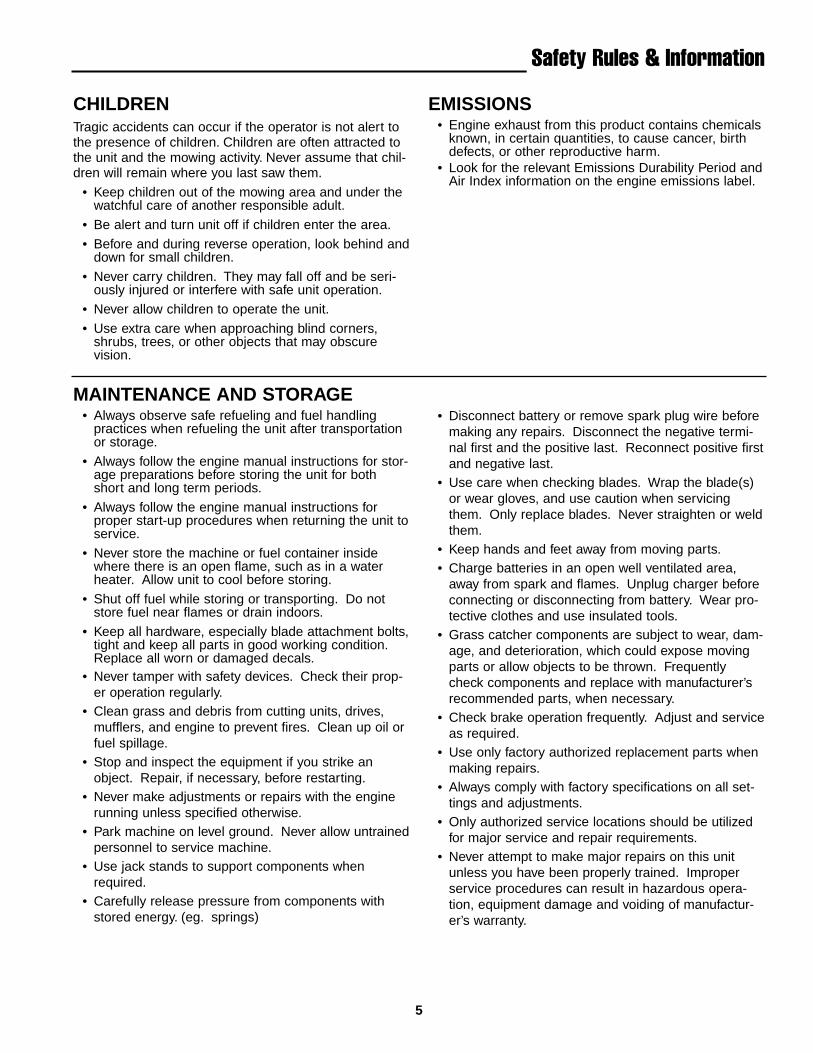
CHILDRENTragic accidents can occur if the operator is not alert tothe presence of children. Children are often attracted tothe unit and the mowing activity. Never assume that chil-dren will remain where you last saw them.
• Keep children out of the mowing area and under thewatchful care of another responsible adult.
• Be alert and turn unit off if children enter the area.
• Before and during reverse operation, look behind anddown for small children.
• Never carry children. They may fall off and be seri-ously injured or interfere with safe unit operation.
• Never allow children to operate the unit.
• Use extra care when approaching blind corners,shrubs, trees, or other objects that may obscurevision.
MAINTENANCE AND STORAGE• Always observe safe refueling and fuel handling
practices when refueling the unit after transportationor storage.
• Always follow the engine manual instructions for stor-age preparations before storing the unit for bothshort and long term periods.
• Always follow the engine manual instructions forproper start-up procedures when returning the unit toservice.
• Never store the machine or fuel container insidewhere there is an open flame, such as in a waterheater. Allow unit to cool before storing.
• Shut off fuel while storing or transporting. Do notstore fuel near flames or drain indoors.
• Keep all hardware, especially blade attachment bolts,tight and keep all parts in good working condition.Replace all worn or damaged decals.
• Never tamper with safety devices. Check their prop-er operation regularly.
• Clean grass and debris from cutting units, drives,mufflers, and engine to prevent fires. Clean up oil orfuel spillage.
• Stop and inspect the equipment if you strike anobject. Repair, if necessary, before restarting.
• Never make adjustments or repairs with the enginerunning unless specified otherwise.
• Park machine on level ground. Never allow untrainedpersonnel to service machine.
• Use jack stands to support components whenrequired.
• Carefully release pressure from components withstored energy. (eg. springs)
• Disconnect battery or remove spark plug wire beforemaking any repairs. Disconnect the negative termi-nal first and the positive last. Reconnect positive firstand negative last.
• Use care when checking blades. Wrap the blade(s)or wear gloves, and use caution when servicingthem. Only replace blades. Never straighten or weldthem.
• Keep hands and feet away from moving parts.• Charge batteries in an open well ventilated area,
away from spark and flames. Unplug charger beforeconnecting or disconnecting from battery. Wear pro-tective clothes and use insulated tools.
• Grass catcher components are subject to wear, dam-age, and deterioration, which could expose movingparts or allow objects to be thrown. Frequentlycheck components and replace with manufacturer’srecommended parts, when necessary.
• Check brake operation frequently. Adjust and serviceas required.
• Use only factory authorized replacement parts whenmaking repairs.
• Always comply with factory specifications on all set-tings and adjustments.
• Only authorized service locations should be utilizedfor major service and repair requirements.
• Never attempt to make major repairs on this unitunless you have been properly trained. Improperservice procedures can result in hazardous opera-tion, equipment damage and voiding of manufactur-er’s warranty.
EMISSIONS• Engine exhaust from this product contains chemicals
known, in certain quantities, to cause cancer, birthdefects, or other reproductive harm.
• Look for the relevant Emissions Durability Period andAir Index information on the engine emissions label.
6
GENERALThis unit has been designed and manufactured to pro-vide you with the safety and reliability you would expectfrom an industry leader in outdoor power equipmentmanufacturing.
Although reading this manual and the safety instructionsit contains will provide you with the necessary basicknowledge to operate this equipment safely and effec-tively, we have placed several safety labels on the unit toremind you of this important information while you areoperating your unit.
All DANGER, WARNING, CAUTION and instructionalmessages on your mower should be carefully read andobeyed. Personal bodily injury can result when theseinstructions are not followed. The information is for yoursafety and it is important.
Safety Decals
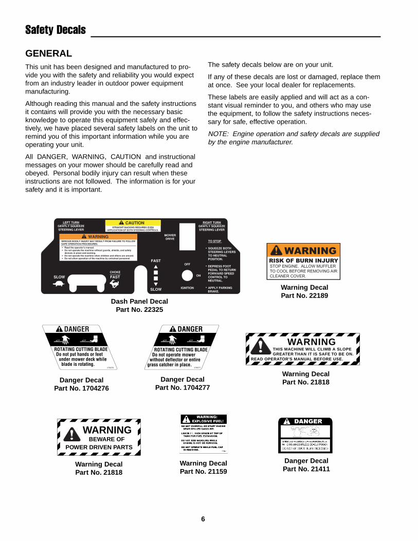
The safety decals below are on your unit.
If any of these decals are lost or damaged, replace themat once. See your local dealer for replacements.
These labels are easily applied and will act as a con-stant visual reminder to you, and others who may usethe equipment, to follow the safety instructions neces-sary for safe, effective operation.
NOTE: Engine operation and safety decals are suppliedby the engine manufacturer.
DANGER
ROTATING CUTTING BLADE Do not put hands or feet under mower deck while blade is rotating.
1704276
WARNINGBEWARE OF
POWER DRIVEN PARTS
DANGER
ROTATING CUTTING BLADE Do not operate mower without deflector or entire grass catcher in place.
1704277
WARNINGTHIS MACHINE WILL CLIMB A SLOPEGREATER THAN IT IS SAFE TO BE ON.
READ OPERATOR'S MANUAL BEFORE USE.
Dash Panel DecalPart No. 22325
Warning DecalPart No. 22189
Danger DecalPart No. 1704276
Danger DecalPart No. 1704277
Warning DecalPart No. 21818
Warning DecalPart No. 21818
Warning DecalPart No. 21159
Danger DecalPart No. 21411

7
CE Compliance Specs
8
Features & Controlsof the Dual Drive Walk-Behind
CONTROL FUNCTIONSThe information below briefly describes the function of individual controls. Starting, stopping, driving, and mowingrequire the combined use of several controls applied in specific sequences. To learn what combination andsequence of controls to use for various tasks see the OPERATION section.
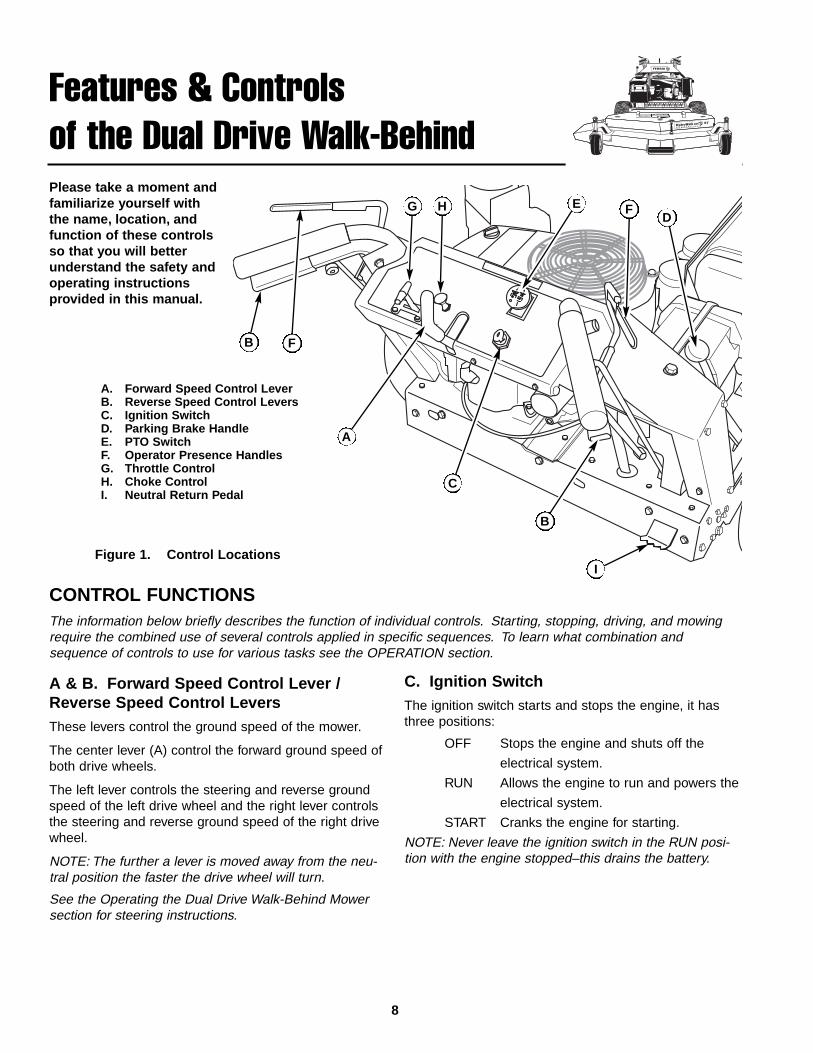
Please take a moment andfamiliarize yourself withthe name, location, andfunction of these controlsso that you will betterunderstand the safety andoperating instructionsprovided in this manual.
A & B. Forward Speed Control Lever /Reverse Speed Control LeversThese levers control the ground speed of the mower.
The center lever (A) control the forward ground speed ofboth drive wheels.
The left lever controls the steering and reverse groundspeed of the left drive wheel and the right lever controlsthe steering and reverse ground speed of the right drivewheel.
NOTE: The further a lever is moved away from the neu-tral position the faster the drive wheel will turn.
See the Operating the Dual Drive Walk-Behind Mowersection for steering instructions.
C. Ignition Switch The ignition switch starts and stops the engine, it hasthree positions:
OFF Stops the engine and shuts off the
electrical system.
RUN Allows the engine to run and powers the
electrical system.
START Cranks the engine for starting.
NOTE: Never leave the ignition switch in the RUN posi-tion with the engine stopped–this drains the battery.
B
I
B
C
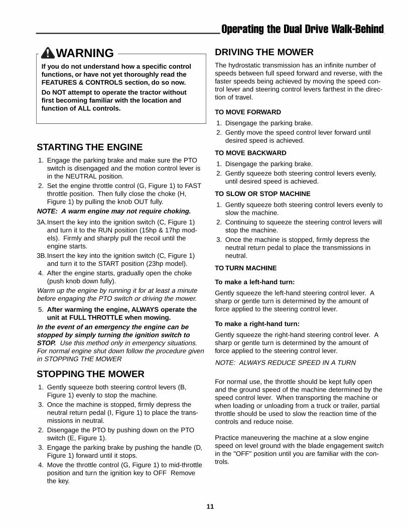
DFEG H
F
A
A. Forward Speed Control LeverB. Reverse Speed Control LeversC. Ignition SwitchD. Parking Brake HandleE. PTO SwitchF. Operator Presence HandlesG. Throttle ControlH. Choke ControlI. Neutral Return Pedal
Figure 1. Control Locations

9
SAFETY INTERLOCKSYSTEM
This unit is equipped with safety interlock switches.These safety systems are present for your safety, do notattempt to bypass safety switches, and never tamperwith safety devices. Check their operation regularly.
Operational SAFETY Checks
Test 1 — Engine should NOT crank if:
• PTO switch is engaged, OR• Parking brake is not engaged, OR• Motion control handle is not in the NEUTRAL posi-
tion
Test 2 — Engine SHOULD crank if:
• PTO switch is NOT engaged, AND• Parking brake is engaged, AND• Motion control handle is in the NEUTRAL position
Test 3 — Engine should SHUT OFF if:
• Operator releases the operator presence handleswith PTO engaged, OR
• Operator releases the operator presence handleswith parking brake disengaged.
Test 4 — Blade Brake Check
Mower blades and mower drive belt should come to acomplete stop within seven seconds after electric PTOswitch is turned off (or operator releases the operatorpresence handles). If mower drive belt does not stopwithin seven seconds, see your dealer.
NOTE: Once the engine has stopped, PTO switch mustbe turned off, parking brake must be engaged, and themotion control handle must be returned to the NEU-TRAL position in order to start the engine.
WARNINGIf the unit does not pass a safety test, do notoperate it. See your authorized dealer. Under nocircumstance should you attempt to defeat thepurpose of the safety interlock system.
Features & Controls
D. Parking Brake HandleThe parking brake is applied by pushing DOWN on theparking brake handle until it stops. To release the park-ing brake, pull UP on the handle until it locks over cen-ter.
E. PTO (Power Take Off) SwitchThe PTO switch engages and disengages the mower.Pull UP on the switch to engage, and push DOWN todisengage.
F. Operator Presence HandlesThese handles are a major factor in the safety interlocksystem of the mower. Both handles are tied together sodepressing one handle depresses both. The operatormust depress the handles in order to disengage theparking brake and engage the PTO switch.
G & H. Throttle / Choke ControlPulling the round choke control knob (H) out fully chokesthe engine for cold starts. (A warm engine may notrequire choking.) Moving the throttle control (G) fullytowards the right is FULL throttle position. Always oper-ate the unit at FULL throttle when mowing.
I. Neutral Return PedalThe neutral return pedal provides a hands-free return toneutral. This is used in conjunction with the ReverseSpeed Control Levers (B) to properly stop the machine.
See the Operating the Dual Drive Walk-Behind Mowersection for steering instructions.
J. Fuel Shut Off Valve (not shown)The fuel shut off valve is located under the fuel tank.Turning the handle until it is VERTICAL will allow fuel tobe supplied to the engine. Turning the handle until it isHORIZONTAL shuts off the fuel supply to the engine.
10
Operating the Dual DriveWalk-BehindGENERAL OPERATING SAFETYBefore first time operation:
• Be sure to read all information in the Safety andOperation sections before attempting to operate thistractor and mower.
• Become familiar with all of the controls and how tostop the unit.
• Drive in an open area without mowing to becomeaccustomed to the unit.
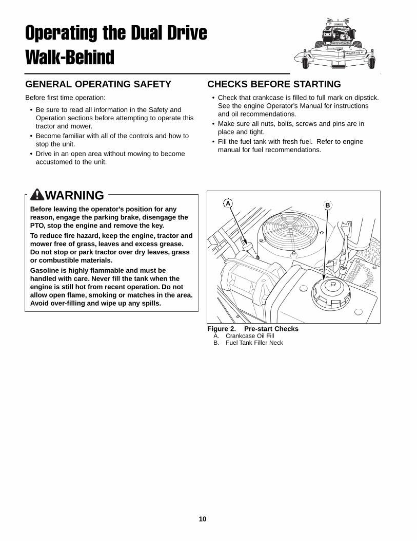
CHECKS BEFORE STARTING• Check that crankcase is filled to full mark on dipstick.
See the engine Operator’s Manual for instructionsand oil recommendations.
• Make sure all nuts, bolts, screws and pins are inplace and tight.
• Fill the fuel tank with fresh fuel. Refer to enginemanual for fuel recommendations.
WARNINGBefore leaving the operator’s position for anyreason, engage the parking brake, disengage thePTO, stop the engine and remove the key.
To reduce fire hazard, keep the engine, tractor andmower free of grass, leaves and excess grease.Do not stop or park tractor over dry leaves, grassor combustible materials.
Gasoline is highly flammable and must behandled with care. Never fill the tank when theengine is still hot from recent operation. Do notallow open flame, smoking or matches in the area.Avoid over-filling and wipe up any spills.
Figure 2. Pre-start ChecksA. Crankcase Oil FillB. Fuel Tank Filler Neck
A B
WARNINGIf you do not understand how a specific controlfunctions, or have not yet thoroughly read theFEATURES & CONTROLS section, do so now.
Do NOT attempt to operate the tractor withoutfirst becoming familiar with the location andfunction of ALL controls.
STARTING THE ENGINE1. Engage the parking brake and make sure the PTO
switch is disengaged and the motion control lever isin the NEUTRAL position.
2. Set the engine throttle control (G, Figure 1) to FASTthrottle position. Then fully close the choke (H,Figure 1) by pulling the knob OUT fully.
NOTE: A warm engine may not require choking.
3A.Insert the key into the ignition switch (C, Figure 1)and turn it to the RUN position (15hp & 17hp mod-els). Firmly and sharply pull the recoil until theengine starts.
3B.Insert the key into the ignition switch (C, Figure 1)and turn it to the START position (23hp model).
4. After the engine starts, gradually open the choke(push knob down fully).
Warm up the engine by running it for at least a minutebefore engaging the PTO switch or driving the mower.
5. After warming the engine, ALWAYS operate theunit at FULL THROTTLE when mowing.
In the event of an emergency the engine can bestopped by simply turning the ignition switch toSTOP. Use this method only in emergency situations.For normal engine shut down follow the procedure givenin STOPPING THE MOWER
STOPPING THE MOWER1. Gently squeeze both steering control levers (B,
Figure 1) evenly to stop the machine.3. Once the machine is stopped, firmly depress the
neutral return pedal (I, Figure 1) to place the trans-missions in neutral.
2. Disengage the PTO by pushing down on the PTOswitch (E, Figure 1).
3. Engage the parking brake by pushing the handle (D,Figure 1) forward until it stops.
4. Move the throttle control (G, Figure 1) to mid-throttleposition and turn the ignition key to OFF Removethe key.
Operating the Dual Drive Walk-Behind
DRIVING THE MOWERThe hydrostatic transmission has an infinite number ofspeeds between full speed forward and reverse, with thefaster speeds being achieved by moving the speed con-trol lever and steering control levers farthest in the direc-tion of travel.
TO MOVE FORWARD
1. Disengage the parking brake.2. Gently move the speed control lever forward until
desired speed is achieved.
TO MOVE BACKWARD
1. Disengage the parking brake.2. Gently squeeze both steering control levers evenly,
until desired speed is achieved.
TO SLOW OR STOP MACHINE
1. Gently squeeze both steering control levers evenly toslow the machine.
2. Continuing to squeeze the steering control levers willstop the machine.
3. Once the machine is stopped, firmly depress theneutral return pedal to place the transmissions inneutral.
TO TURN MACHINE
To make a left-hand turn:
Gently squeeze the left-hand steering control lever. Asharp or gentle turn is determined by the amount offorce applied to the steering control lever.
To make a right-hand turn:
Gently squeeze the right-hand steering control lever. Asharp or gentle turn is determined by the amount offorce applied to the steering control lever.
NOTE: ALWAYS REDUCE SPEED IN A TURN
For normal use, the throttle should be kept fully openand the ground speed of the machine determined by thespeed control lever. When transporting the machine orwhen loading or unloading from a truck or trailer, partialthrottle should be used to slow the reaction time of thecontrols and reduce noise.
Practice maneuvering the machine at a slow enginespeed on level ground with the blade engagement switchin the "OFF" position until you are familiar with the con-trols.
11
12
Operating the Dual Drive Walk-Behind
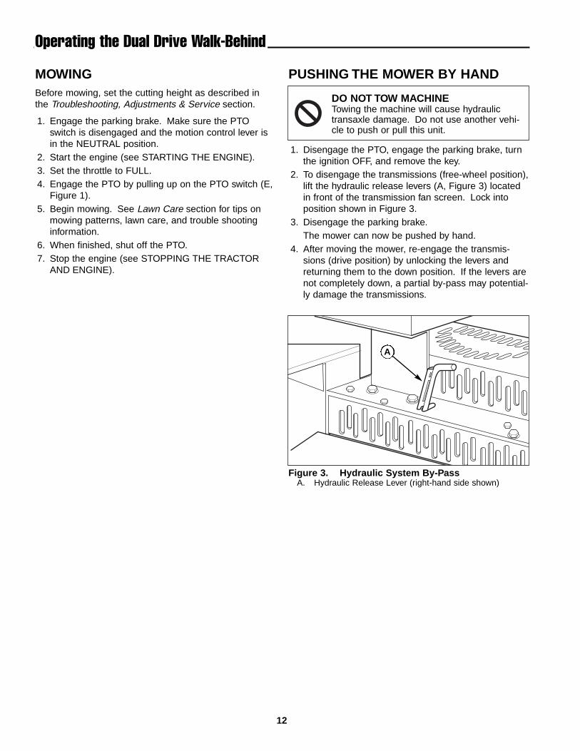
Figure 3. Hydraulic System By-PassA. Hydraulic Release Lever (right-hand side shown)
A
MOWINGBefore mowing, set the cutting height as described inthe Troubleshooting, Adjustments & Service section.
1. Engage the parking brake. Make sure the PTOswitch is disengaged and the motion control lever isin the NEUTRAL position.
2. Start the engine (see STARTING THE ENGINE).3. Set the throttle to FULL.4. Engage the PTO by pulling up on the PTO switch (E,
Figure 1).5. Begin mowing. See Lawn Care section for tips on
mowing patterns, lawn care, and trouble shootinginformation.
6. When finished, shut off the PTO.7. Stop the engine (see STOPPING THE TRACTOR
AND ENGINE).
PUSHING THE MOWER BY HAND
1. Disengage the PTO, engage the parking brake, turnthe ignition OFF, and remove the key.
2. To disengage the transmissions (free-wheel position),lift the hydraulic release levers (A, Figure 3) locatedin front of the transmission fan screen. Lock intoposition shown in Figure 3.
3. Disengage the parking brake.The mower can now be pushed by hand.
4. After moving the mower, re-engage the transmis-sions (drive position) by unlocking the levers andreturning them to the down position. If the levers arenot completely down, a partial by-pass may potential-ly damage the transmissions.
DO NOT TOW MACHINETowing the machine will cause hydraulictransaxle damage. Do not use another vehi-cle to push or pull this unit.
13
Operating the Dual Drive Walk-Behind
STORAGE
Temporary Storage (30 Days Or Less)Remember, the fuel tank will still contain some gasoline,so never store the unit indoors or in any other areawhere fuel vapor could travel to any ignition source. Fuelvapor is also toxic if inhaled, so never store the unit inany structure used for human or animal habitation.
Here is a checklist of things to do when storing your unittemporarily or in between uses:
• Keep the unit in an area away from where childrenmay come into contact with it. If there’s any chanceof unauthorized use, remove the spark plug (s) andput in a safe place. Be sure the spark plug opening isprotected from foreign objects with a suitable cover.
• If the unit can’t be stored on a reasonable level sur-face, chock the wheels.
• Clean all grass and dirt from the mower.
Long Term Storage (Longer Than 30 Days)Before you store your unit for the off-season, read theMaintenance and Storage instructions in the SafetyRules section, then perform the following steps:
1. Drain crankcase oil while engine is hot and refill witha grade of oil that will be required when unit is usedagain.
2. Prepare the mower deck for storage as follows:
a. Remove mower deck from the unit.
b. Clean underside of mower deck.
c. Coat all bare metal surfaces with paint or light coatof oil to prevent rusting.
3. Clean external surfaces and engine.4. Prepare engine for storage. See engine owner’s
manual.5. Clean any dirt or grass from cylinder head cooling
fins, engine housing and air cleaner element.6. Cover air cleaner and exhaust outlet tightly with plas-
tic or other waterproof material to keep out moisture,dirt and insects.
7. Completely grease and oil unit as outlined in theNormal Care section.
8. Clean up unit and apply paint or rust preventative toany areas where paint is chipped or damaged.
9. Be sure the battery is filled to the proper level withwater and is fully charged. Battery life will beincreased if it is removed, put in a cool, dry placeand fully charged about once a month. If battery isleft in unit, disconnect the negative cable.
WARNINGNever store the unit, with gasoline in engine orfuel tank, in a heated shelter or in enclosed,poorly ventilated enclosures. Gasoline fumes mayreach an open flame, spark or pilot light (such asa furnace, water heater, clothes dryer, etc.) andcause an explosion.
Handle gasoline carefully. It is highly flammableand careless use could result in serious firedamage to your person or property.
Drain fuel into an approved container outdoorsaway from open flame or sparks.
10. Drain fuel system completely or add a gasoline stabi-lizer to the fuel system. If you have chosen to use afuel stabilizer and have not drained the fuel system,follow all safety instructions and storage precautionsin this manual to prevent the possibility of fire fromthe ignition of gasoline fumes. Remember, gasolinefumes can travel to distant sources of ignition andignite, causing risk of explosion and fire.
NOTE: Gasoline, if permitted to stand unused forextended periods (30 days or more), may developgummy deposits which can adversely affect the enginecarburetor and cause engine malfunction. To avoid thiscondition, add a gasoline stabilizer to the fuel tank andrun the engine a few minutes, or drain all fuel from theunit before placing it in storage.
STARTING AFTER LONG TERMSTORAGEBefore starting the unit after it has been stored for a longperiod of time, perform the following steps.
1. Remove any blocks from under the unit.2. Install the battery if it was removed.3. Unplug the exhaust outlet and air cleaner.4. Fill the fuel tank with fresh gasoline. See engine
manual for recommendations.5. See engine owner’s manual and follow all instruc-
tions for preparing engine after storage.6. Check crankcase oil level and add proper oil if
necessary. If any condensation has developed duringstorage, drain crankcase oil and refill.
7. Inflate tires to proper pressure. Check fluid levels.8. Start the engine and let it run slowly. DO NOT run at
high speed immediately after starting. Be sure to runengine only outdoors or in well ventilated area.
14
RegularMaintenanceMAINTENANCE SCHEDULE & PROCEDURESThe following schedule should be followed for normal care of your mower. You will need to keep a record of youroperating time.
See Before Before Every Every Every SpringSAFETY ITEMS Page First Use Each Use 5 Hours 25 Hours 100 Hours & Fall
Check Safety Interlock System 9 X X X
Check Mower Blade Stopping Time 23 X XSee Before Before Every Every Every Spring
NORMAL CARE ITEMS Page First Use Each Use 5 Hours 25 Hours 100 Hours & Fall
Check Rider/Mower for loose hardware — X X
Check Engine Oil Level 15* X X X X
Check Engine Air Filter 15* X ****X
Change Engine Oil & Filter ** 15* ****X Every 50 Hours ****X
Change Transmission Oil & Filters 28 ****X Every 500 Hours
Lubricate Mower & Mower Deck 16 X ****X
Check Mower Deck Belt Tension*** 24/25 X
Check Tire Pressure 14 X ****X
Check Hydraulic Fluid 15 X ****X
Check Fuel Filter 15 X
Clean Battery & Cables 17 X
Clean & Sharpen Mower Blades 18 X
Inspect Spark Plug 15* X
* See the engine manufacturer's owner's manual.** Change original engine oil after first 5 hours of operation.
*** Check belt tension after first 5 hours of operation.**** More often in hot (over 85° F: 30° C) weather or dusty operating conditions.
Tire Pressure
Front 25 psi (172 kPa)
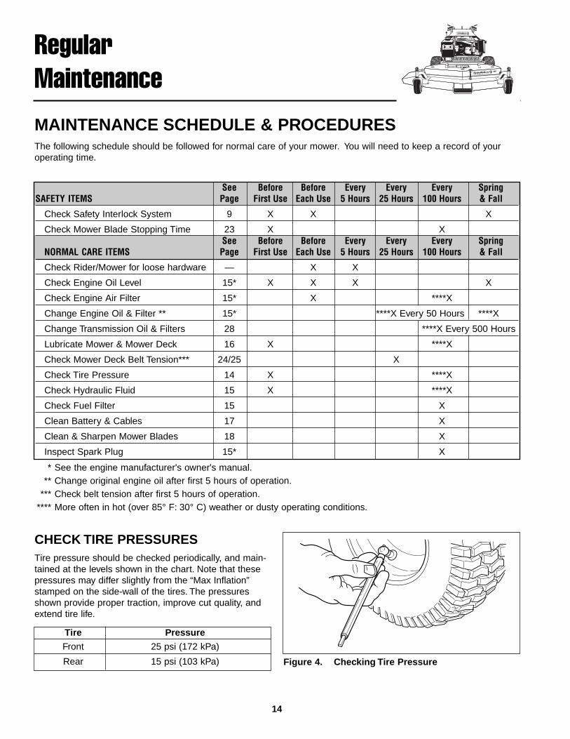
Rear 15 psi (103 kPa) Figure 4. Checking Tire Pressure
CHECK TIRE PRESSURESTire pressure should be checked periodically, and main-tained at the levels shown in the chart. Note that thesepressures may differ slightly from the “Max Inflation”stamped on the side-wall of the tires. The pressuresshown provide proper traction, improve cut quality, andextend tire life.
15
CHECKING / ADDING FUELTo add fuel:
1. Remove the fuel cap (see A, Figure 2).2. Fill the tank to the bottom of the filler neck. This will
allow for fuel expansion.NOTE: Do not overfill. Refer to your engine manual forspecific fuel recommendations.
3. Install and hand tighten the fuel cap.4. Repeat same process for opposite tank.
FUEL FILTERThe fuel filter (D, Figure 2) is located in the fuel linebetween fuel shut off valve and carburetor, near the fuelpump. If filter is dirty or clogged, replace as follows:
1. Shut off the fuel tank selection valve.2. Disconnect the negative battery cable.3. Place a container below the filter to catch spilled fuel.4. Using a pliers, open and slide hose clamps from fuel
filter.5. Remove hoses from filter.6. Install new filter in proper flow direction in fuel line.7. Secure with hose clamps.8. Reconnect the negative battery cable when finished.
OIL & FILTER CHANGERefer to engine owners manual.
CHECK / CHANGE AIR FILTERRefer to engine owners manual.
REPLACE SPARK PLUGRefer to engine owners manual.
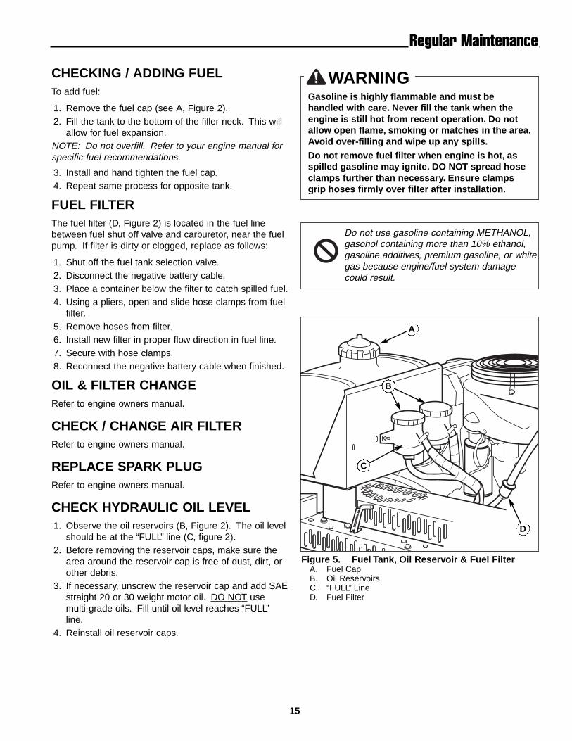
CHECK HYDRAULIC OIL LEVEL1. Observe the oil reservoirs (B, Figure 2). The oil level
should be at the “FULL” line (C, figure 2).2. Before removing the reservoir caps, make sure the
area around the reservoir cap is free of dust, dirt, orother debris.
3. If necessary, unscrew the reservoir cap and add SAEstraight 20 or 30 weight motor oil. DO NOT usemulti-grade oils. Fill until oil level reaches “FULL”line.
4. Reinstall oil reservoir caps.
Regular Maintenance
WARNINGGasoline is highly flammable and must behandled with care. Never fill the tank when theengine is still hot from recent operation. Do notallow open flame, smoking or matches in the area.Avoid over-filling and wipe up any spills.
Do not remove fuel filter when engine is hot, asspilled gasoline may ignite. DO NOT spread hoseclamps further than necessary. Ensure clampsgrip hoses firmly over filter after installation.
Do not use gasoline containing METHANOL,gasohol containing more than 10% ethanol,gasoline additives, premium gasoline, or whitegas because engine/fuel system damagecould result.
D
B
C
Figure 5. Fuel Tank, Oil Reservoir & Fuel FilterA. Fuel CapB. Oil ReservoirsC. “FULL” LineD. Fuel Filter
A
16
Regular Maintenance
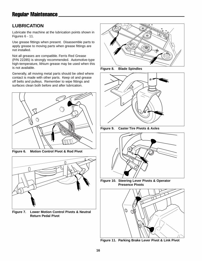
LUBRICATIONLubricate the machine at the lubrication points shown inFigures 6 - 11.
Use grease fittings when present. Disassemble parts toapply grease to moving parts when grease fittings arenot installed.
Not all greases are compatible. Ferris Red Grease(P/N 22285) is strongly recommended. Automotive-typehigh-temperature, lithium grease may be used when thisis not available.
Generally, all moving metal parts should be oiled wherecontact is made with other parts. Keep oil and greaseoff belts and pulleys. Remember to wipe fittings andsurfaces clean both before and after lubrication.
Figure 8. Blade Spindles
Figure 9. Caster Tire Pivots & Axles
Figure 10. Steering Lever Pivots & OperatorPresence Pivots
Figure 11. Parking Brake Lever Pivot & Link Pivot
Figure 6. Motion Control Pivot & Rod Pivot
Figure 7. Lower Motion Control Pivots & NeutralReturn Pedal Pivot

17
Regular Maintenance
BATTERY MAINTENANCE
Checking the Battery FluidNOTE: It is not necessary to check the battery fluidlevel if machine is equipped with a maintenance-freebattery.
1. Remove the battery box cover to access the battery.2. Remove the battery filler cap(s) (A, Figure 12). Fluid
must be even with the split ring full mark. If not, adddistilled water.
3. Reinstall the filler cap(s).
Cleaning the Battery and Cables1. Disconnect the cables from the battery, negative
cable first (C, Figure 12).2. Clean the battery terminals and cable ends with a
wire brush until shiny.3. Reinstall the battery and reattach the battery cables,
positive cable first (see B, Figure 12)4. Coat the cable ends and battery terminals with petro-
leum jelly or non-conducting grease.
WARNINGBe careful when handling the battery. Avoidspilling electrolyte. Keep flames and sparks awayfrom the battery.
When removing or installing battery cables,disconnect the negative cable FIRST and reconnectit LAST. If not done in this order, the positiveterminal can be shorted to the frame by a tool.
A
B
C
Figure 12. Battery CompartmentA. Vent Cap(s)B. Positive (+) Cable & TerminalC. Negative (-) Cable & Terminal
18
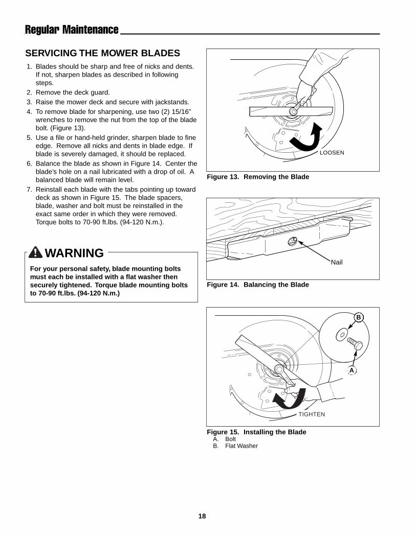
SERVICING THE MOWER BLADES1. Blades should be sharp and free of nicks and dents.
If not, sharpen blades as described in followingsteps.
2. Remove the deck guard.3. Raise the mower deck and secure with jackstands.4. To remove blade for sharpening, use two (2) 15/16”
wrenches to remove the nut from the top of the bladebolt. (Figure 13).
5. Use a file or hand-held grinder, sharpen blade to fineedge. Remove all nicks and dents in blade edge. Ifblade is severely damaged, it should be replaced.
6. Balance the blade as shown in Figure 14. Center theblade’s hole on a nail lubricated with a drop of oil. Abalanced blade will remain level.
7. Reinstall each blade with the tabs pointing up towarddeck as shown in Figure 15. The blade spacers,blade, washer and bolt must be reinstalled in theexact same order in which they were removed.Torque bolts to 70-90 ft.lbs. (94-120 N.m.).
WARNINGFor your personal safety, blade mounting boltsmust each be installed with a flat washer thensecurely tightened. Torque blade mounting boltsto 70-90 ft.lbs. (94-120 N.m.)
LOOSEN
TIGHTEN
Nail
Figure 13. Removing the Blade
Figure 14. Balancing the Blade
Figure 15. Installing the BladeA. BoltB. Flat Washer
B
A
Regular Maintenance
19
TroubleshootingAdjustments & Service
TROUBLESHOOTINGWhile normal care and regular maintenance will extendthe life of your equipment, prolonged or constant usemay eventually require that service be performed toallow it to continue operating properly.
The troubleshooting guide below lists the most commonproblems, their causes and remedies.
See the information on the following pages for instruc-tions on how to perform most of these minor adjust-ments and service repairs yourself. If you prefer, all ofthese procedures can be performed for you by your localauthorized dealer.
WARNINGTo avoid serious injury, perform maintenance onthe mower only when the engine is stopped andthe parking brake engaged.
Always remove the ignition key, disconnect thespark plug wire and fasten it away from the plugbefore beginning the maintenance, to preventaccidental starting of the engine.
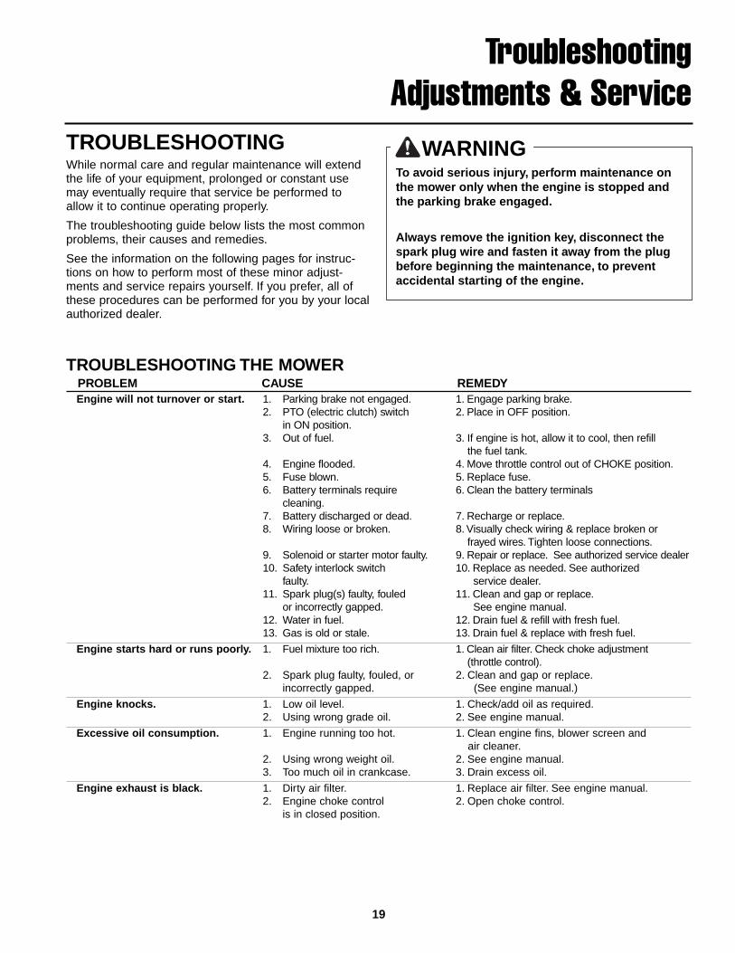
TROUBLESHOOTING THE MOWERPROBLEM CAUSE REMEDYEngine will not turnover or start. 1. Parking brake not engaged. 1. Engage parking brake.
2. PTO (electric clutch) switch 2. Place in OFF position.in ON position.
3. Out of fuel. 3. If engine is hot, allow it to cool, then refill the fuel tank.
4. Engine flooded. 4. Move throttle control out of CHOKE position.5. Fuse blown. 5. Replace fuse.6. Battery terminals require 6. Clean the battery terminals
cleaning.7. Battery discharged or dead. 7. Recharge or replace.8. Wiring loose or broken. 8. Visually check wiring & replace broken or
frayed wires. Tighten loose connections.9. Solenoid or starter motor faulty. 9. Repair or replace. See authorized service dealer 10. Safety interlock switch 10. Replace as needed. See authorized
faulty. service dealer.11. Spark plug(s) faulty, fouled 11. Clean and gap or replace.
or incorrectly gapped. See engine manual.12. Water in fuel. 12. Drain fuel & refill with fresh fuel.13. Gas is old or stale. 13. Drain fuel & replace with fresh fuel.
Engine starts hard or runs poorly. 1. Fuel mixture too rich. 1. Clean air filter. Check choke adjustment (throttle control).
2. Spark plug faulty, fouled, or 2. Clean and gap or replace.incorrectly gapped. (See engine manual.)
Engine knocks. 1. Low oil level. 1. Check/add oil as required.2. Using wrong grade oil. 2. See engine manual.
Excessive oil consumption. 1. Engine running too hot. 1. Clean engine fins, blower screen andair cleaner.
2. Using wrong weight oil. 2. See engine manual.3. Too much oil in crankcase. 3. Drain excess oil.
Engine exhaust is black. 1. Dirty air filter. 1. Replace air filter. See engine manual.2. Engine choke control 2. Open choke control.
is in closed position.

20
Rider Troubleshooting Continued.PROBLEM CAUSE REMEDYEngine runs, but mower will 1. Transmission release lever(s) 1. Move into drive position.not drive. in “neutral” position.
2. Belt is broken. 2. See Drive Belt Replacement.3. Drive belt slips. 3. See problem and cause below.4. Brake is not fully released. 4. See authorized service dealer
Transmission drive belt slips. 1. Pulleys or belt greasy or oily. 1. Clean as required.2. Belt stretched or worn. 2. Replace belt.
Brake will not hold. 1. Internal brake disc on 1. See authorized service dealertransaxle worn.
Mower steers hard or 1. Steering linkage is loose. 1. Check and tighten any loose connections.handles poorly. 2. Improper tire inflation. 2. See Regular Maintenance Section.
TROUBLESHOOTING THE MOWER DECKPROBLEM CAUSE REMEDYMower cut is uneven. 1. Mower not leveled properly. 1. See Mower Adjustment.
2. Drive tires not inflated 2. See Regular Maintenance Section.equally or properly.
Mower cut is rough looking. 1. Engine speed too slow. 1. Set throttle to full.2. Ground speed too fast. 2. Decrease Ground Speed.3. Blades are dull. 3. Sharpen or replace blades.
See Mower Blade Service.4. Mower drive belt slipping 4. Clean or replace belt as necessary.
because it is oily or worn.5. Blades not properly fastened 5. See Servicing the Mower Blades.
to arbors.
Engine stalls easily with 1. Engine speed too slow. 1. Set to full throttle.mower engaged. 2. Ground speed too fast. 2. Decrease Ground Speed.
3. Cutting height set too low. 3. Cut tall grass at maximum cuttingheight during first pass.
4. Discharge chute jamming 4. Cut grass with discharge pointing towardwith cut grass. previously cut area.
Excessive mower vibration. 1. Blade mounting screws 1. Tighten to 70-90 ft.lbs. (94-120 N.m.).are loose.
2. Mower blades, arbors, 2. Check and replace as necessary.or pulleys are bent.
3. Mower blades are out 3. Remove, sharpen, and balance blades.of balance. See Maintenance Section.
4. Belt installed incorrectly. 4. Reinstall Correctly.
Excessive belt wear or breakage. 1. Bent or rough pulleys. 1. Repair or replace.2. Using incorrect belt. 2. Replace with correct belt.
Mower drive belt slips 1. Belt tension improperly adjusted. 1. Adjust belt tension. See Belt Replacementor fails to drive. 1. Idler pulley spring broken or not 1. Repair or adjust as needed.
properly adjusted.2. Mower drive belt broken. 2. Replace drive belt.
Troubleshooting, Adjustment & Service
21
Troubleshooting, Adjustment & Service
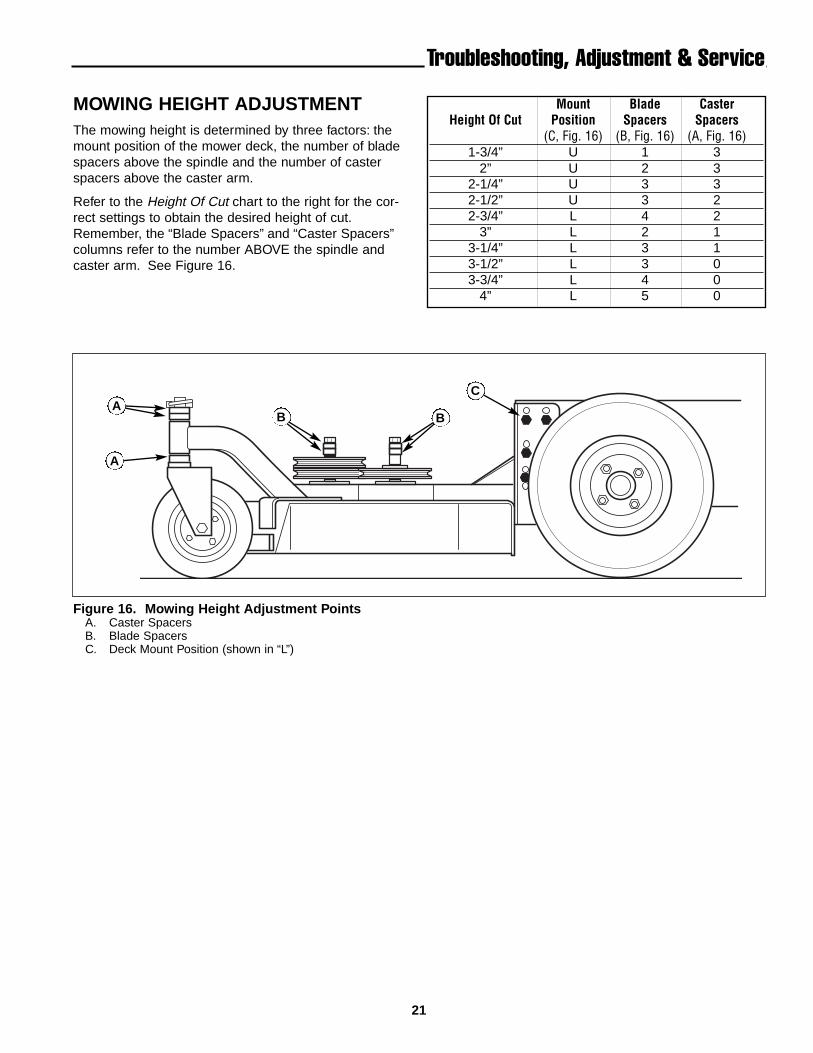
MOWING HEIGHT ADJUSTMENTThe mowing height is determined by three factors: themount position of the mower deck, the number of bladespacers above the spindle and the number of casterspacers above the caster arm.
Refer to the Height Of Cut chart to the right for the cor-rect settings to obtain the desired height of cut.Remember, the “Blade Spacers” and “Caster Spacers”columns refer to the number ABOVE the spindle andcaster arm. See Figure 16.
Mount Blade CasterHeight Of Cut Position Spacers Spacers
(C, Fig. 16) (B, Fig. 16) (A, Fig. 16)1-3/4” U 1 3
2” U 2 32-1/4” U 3 32-1/2” U 3 22-3/4” L 4 2
3” L 2 13-1/4” L 3 13-1/2” L 3 03-3/4” L 4 0
4” L 5 0
Figure 16. Mowing Height Adjustment PointsA. Caster SpacersB. Blade SpacersC. Deck Mount Position (shown in “L”)
C
BA
B
A
22
Troubleshooting, Adjustment & Service
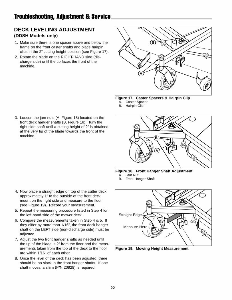
DECK LEVELING ADJUSTMENT(DDSH Models only)1. Make sure there is one spacer above and below the
frame on the front caster shafts and place hairpinclips in the 2” cutting height position (see Figure 17).
2. Rotate the blade on the RIGHT-HAND side (dis-charge side) until the tip faces the front of themachine.
Figure 17. Caster Spacers & Hairpin ClipA. Caster SpacerB. Hairpin Clip
Figure 18. Front Hanger Shaft AdjustmentA. Jam NutB. Front Hanger Shaft
Figure 19. Mowing Height Measurement
Straight Edge
Measure Here
3. Loosen the jam nuts (A, Figure 18) located on thefront deck hanger shafts (B, Figure 18). Turn theright side shaft until a cutting height of 2” is obtainedat the very tip of the blade towards the front of themachine.
4. Now place a straight edge on top of the cutter deckapproximately 1” to the outside of the front deckmount on the right side and measure to the floor(see Figure 19). Record your measurement.
5. Repeat the measuring procedure listed in Step 4 forthe left-hand side of the mower deck.
6. Compare the measurements taken in Step 4 & 5. Ifthey differ by more than 1/16”, the front deck hangershaft on the LEFT side (non-discharge side) must beadjusted.
7. Adjust the two front hanger shafts as needed untilthe tip of the blade is 2” from the floor and the meas-urements taken from the top of the deck to the floorare within 1/16" of each other.
8. Once the level of the deck has been adjusted, thereshould be no slack in the front hanger shafts. If oneshaft moves, a shim (P/N 20928) is required.
A
B
B
A
23
Troubleshooting, Adjustment & Service
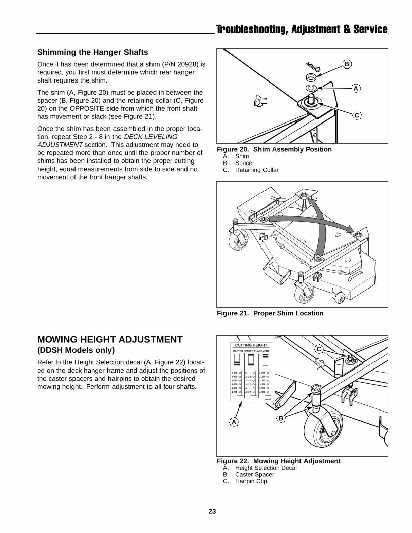
Figure 20. Shim Assembly PositionA. ShimB. SpacerC. Retaining Collar
Figure 21. Proper Shim Location
B
Shimming the Hanger ShaftsOnce it has been determined that a shim (P/N 20928) isrequired, you first must determine which rear hangershaft requires the shim.
The shim (A, Figure 20) must be placed in between thespacer (B, Figure 20) and the retaining collar (C, Figure20) on the OPPOSITE side from which the front shafthas movement or slack (see Figure 21).
Once the shim has been assembled in the proper loca-tion, repeat Step 2 - 8 in the DECK LEVELINGADJUSTMENT section. This adjustment may need tobe repeated more than once until the proper number ofshims has been installed to obtain the proper cuttingheight, equal measurements from side to side and nomovement of the front hanger shafts.
Figure 22. Mowing Height AdjustmentA. Height Selection DecalB. Caster SpacerC. Hairpin Clip
46028
CUTTING HEIGHTCASTER SPACER PLACEMENT
2-1/4
2-3/4
3-1/4
3-3/4
4-1/4
4-3/4
2
2-1/2
3
3-1/2
4
4-1/2
1-3/4
2-1/4
2-3/4
3-1/4
3-3/4
4-1/4
MOWING HEIGHT ADJUSTMENT(DDSH Models only)Refer to the Height Selection decal (A, Figure 22) locat-ed on the deck hanger frame and adjust the positions ofthe caster spacers and hairpins to obtain the desiredmowing height. Perform adjustment to all four shafts.
A
A
C
B
C
24
Troubleshooting, Adjustment & Service
MOWER BELT REPLACEMENT ANDADJUSTMENT
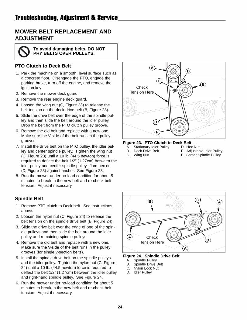
PTO Clutch to Deck Belt1. Park the machine on a smooth, level surface such as
a concrete floor. Disengage the PTO, engage theparking brake, turn off the engine, and remove theignition key.
2. Remove the mower deck guard.3. Remove the rear engine deck guard.4. Loosen the wing nut (C, Figure 23) to release the
belt tension on the deck drive belt (B, Figure 23).5. Slide the drive belt over the edge of the spindle pul-
ley and then slide the belt around the idler pulley.Drop the belt from the PTO clutch pulley groove.
6. Remove the old belt and replace with a new one.Make sure the V-side of the belt runs in the pulleygrooves.
7. Install the drive belt on the PTO pulley, the idler pul-ley and center spindle pulley. Tighten the wing nut(C, Figure 23) until a 10 lb. (44.5 newton) force isrequired to deflect the belt 1/2” (1,27cm) between theidler pulley and center spindle pulley. Jam hex nut(D, Figure 23) against anchor. See Figure 23.
8. Run the mower under no-load condition for about 5minutes to break-in the new belt and re-check belttension. Adjust if necessary.
Spindle Belt1. Remove PTO clutch to Deck belt. See instructions
above.2. Loosen the nylon nut (C, Figure 24) to release the
belt tension on the spindle drive belt (B, Figure 24).3. Slide the drive belt over the edge of one of the spin-
dle pulleys and then slide the belt around the idlerpulley and remaining spindle pulleys.
4. Remove the old belt and replace with a new one.Make sure the V-side of the belt runs in the pulleygrooves (for single v-section belts).
5. Install the spindle drive belt on the spindle pulleysand the idler pulley. Tighten the nylon nut (C, Figure24) until a 10 lb. (44.5 newton) force is required todeflect the belt 1/2” (1,27cm) between the idler pulleyand right-hand spindle pulley. See Figure 24.
6. Run the mower under no-load condition for about 5minutes to break-in the new belt and re-check belttension. Adjust if necessary.
Figure 23. PTO Clutch to Deck BeltA. Stationary Idler Pulley D. Hex NutB. Deck Drive Belt E. Adjustable Idler PulleyC. Wing Nut F. Center Spindle Pulley
Figure 24. Spindle Drive BeltA. Spindle PulleyB. Spindle Drive BeltC. Nylon Lock NutD. Idler Pulley
A
B
E
F
B A
CheckTension Here
CheckTension Here D
C
A
A
C
D
To avoid damaging belts, DO NOTPRY BELTS OVER PULLEYS.
25
Troubleshooting, Adjustment & Service
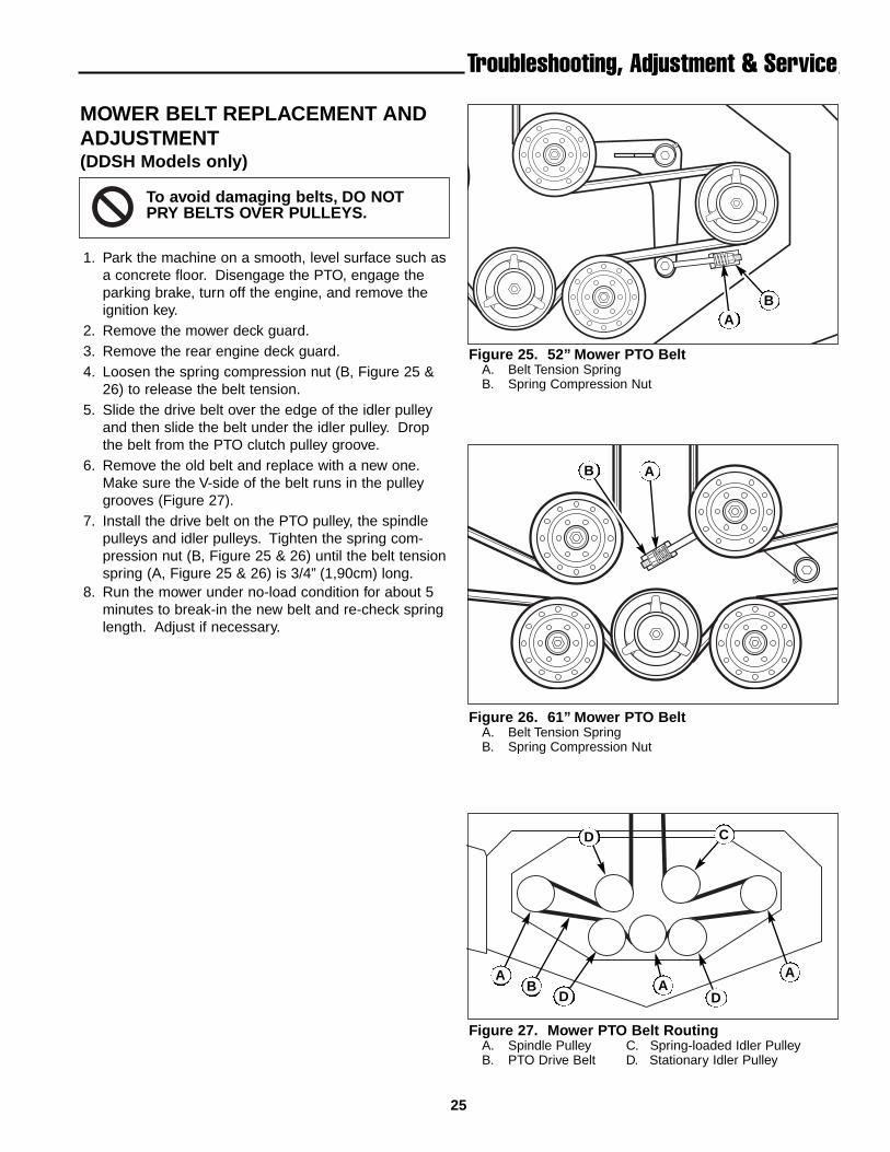
MOWER BELT REPLACEMENT ANDADJUSTMENT(DDSH Models only)
1. Park the machine on a smooth, level surface such asa concrete floor. Disengage the PTO, engage theparking brake, turn off the engine, and remove theignition key.
2. Remove the mower deck guard.3. Remove the rear engine deck guard.4. Loosen the spring compression nut (B, Figure 25 &
26) to release the belt tension.5. Slide the drive belt over the edge of the idler pulley
and then slide the belt under the idler pulley. Dropthe belt from the PTO clutch pulley groove.
6. Remove the old belt and replace with a new one.Make sure the V-side of the belt runs in the pulleygrooves (Figure 27).
7. Install the drive belt on the PTO pulley, the spindlepulleys and idler pulleys. Tighten the spring com-pression nut (B, Figure 25 & 26) until the belt tensionspring (A, Figure 25 & 26) is 3/4” (1,90cm) long.
8. Run the mower under no-load condition for about 5minutes to break-in the new belt and re-check springlength. Adjust if necessary.
Figure 25. 52” Mower PTO BeltA. Belt Tension SpringB. Spring Compression Nut
Figure 26. 61” Mower PTO BeltA. Belt Tension SpringB. Spring Compression Nut
Figure 27. Mower PTO Belt RoutingA. Spindle Pulley C. Spring-loaded Idler PulleyB. PTO Drive Belt D. Stationary Idler Pulley
A
AA
D
D D
A
C
B
B
AB
To avoid damaging belts, DO NOTPRY BELTS OVER PULLEYS.
26
Troubleshooting, Adjustment & Service
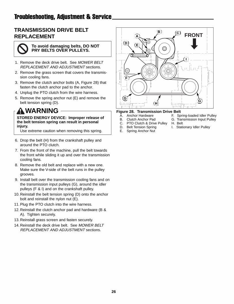
TRANSMISSION DRIVE BELTREPLACEMENT
1. Remove the deck drive belt. See MOWER BELTREPLACEMENT AND ADJUSTMENT sections.
2. Remove the grass screen that covers the transmis-sion cooling fans.
3. Remove the clutch anchor bolts (A, Figure 28) thatfasten the clutch anchor pad to the anchor.
4. Unplug the PTO clutch from the wire harness.5. Remove the spring anchor nut (E) and remove the
belt tension spring (D).
6. Drop the belt (H) from the crankshaft pulley andaround the PTO clutch.
7. From the front of the machine, pull the belt towardsthe front while sliding it up and over the transmissioncooling fans.
8. Remove the old belt and replace with a new one.Make sure the V-side of the belt runs in the pulleygrooves.
9. Install belt over the transmission cooling fans and onthe transmission input pulleys (G), around the idlerpulleys (F & I) and on the crankshaft pulley.
10. Reinstall the belt tension spring (D) onto the anchorbolt and reinstall the nylon nut (E).
11. Plug the PTO clutch into the wire harness.12. Reinstall the clutch anchor pad and hardware (B &
A). Tighten securely.13. Reinstall grass screen and fasten securely.14. Reinstall the deck drive belt. See MOWER BELT
REPLACEMENT AND ADJUSTMENT sections.
FRONT
WARNINGSTORED ENERGY DEVICE: Improper release ofthe belt tension spring can result in personalinjury.
Use extreme caution when removing this spring.
To avoid damaging belts, DO NOTPRY BELTS OVER PULLEYS.
Figure 28. Transmission Drive BeltA. Anchor Hardware F. Spring-loaded Idler PulleyB. Clutch Anchor Pad G. Transmission Input PulleyC. PTO Clutch & Drive Pulley H. BeltD. Belt Tension Spring I. Stationary Idler PulleyE. Spring Anchor Nut
B
D
H
C
I
E
A
F
GG
27
Troubleshooting, Adjustment & Service
TRANSMISSION NEUTRAL &TRACKING ADJUSTMENTS
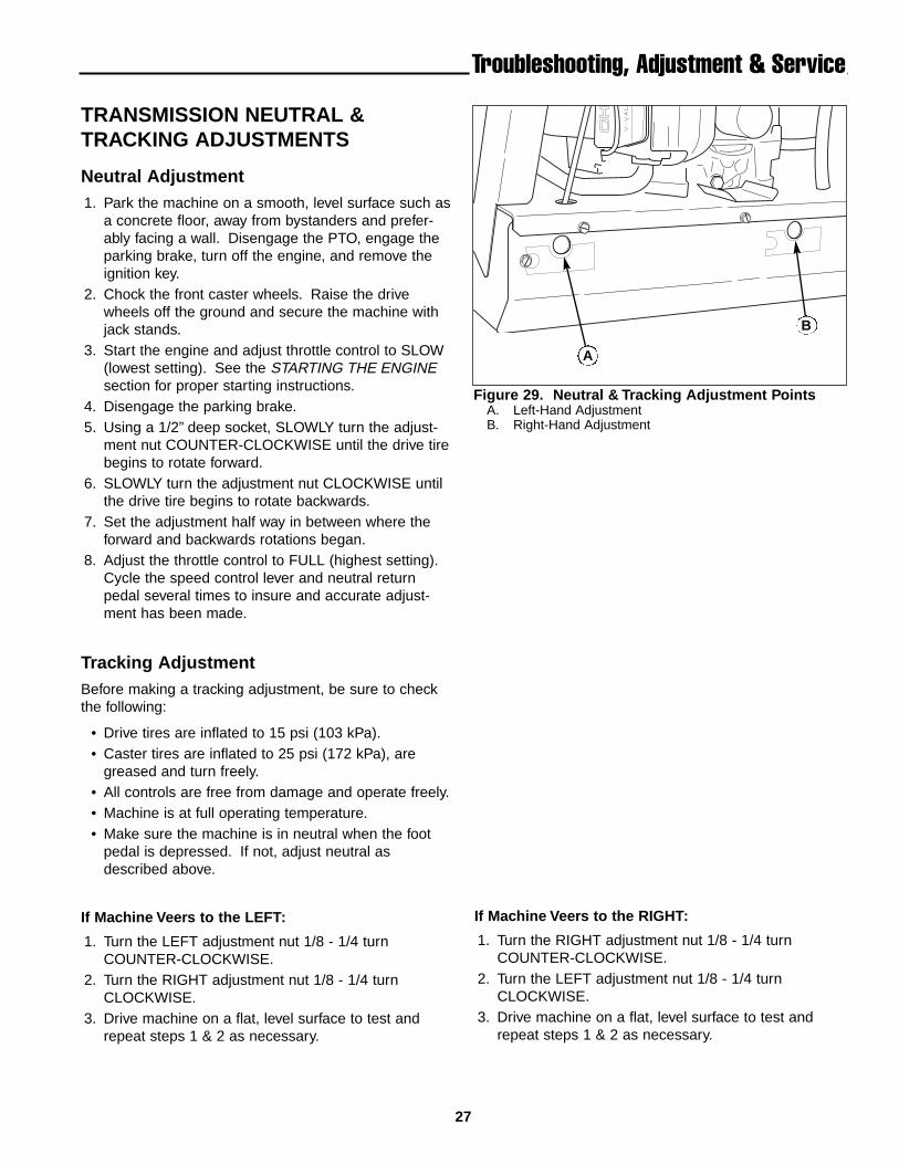
Neutral Adjustment1. Park the machine on a smooth, level surface such as
a concrete floor, away from bystanders and prefer-ably facing a wall. Disengage the PTO, engage theparking brake, turn off the engine, and remove theignition key.
2. Chock the front caster wheels. Raise the drivewheels off the ground and secure the machine withjack stands.
3. Start the engine and adjust throttle control to SLOW(lowest setting). See the STARTING THE ENGINEsection for proper starting instructions.
4. Disengage the parking brake.5. Using a 1/2” deep socket, SLOWLY turn the adjust-
ment nut COUNTER-CLOCKWISE until the drive tirebegins to rotate forward.
6. SLOWLY turn the adjustment nut CLOCKWISE untilthe drive tire begins to rotate backwards.
7. Set the adjustment half way in between where theforward and backwards rotations began.
8. Adjust the throttle control to FULL (highest setting).Cycle the speed control lever and neutral returnpedal several times to insure and accurate adjust-ment has been made.
Tracking AdjustmentBefore making a tracking adjustment, be sure to checkthe following:
• Drive tires are inflated to 15 psi (103 kPa).• Caster tires are inflated to 25 psi (172 kPa), are
greased and turn freely.• All controls are free from damage and operate freely.• Machine is at full operating temperature.• Make sure the machine is in neutral when the foot
pedal is depressed. If not, adjust neutral asdescribed above.
If Machine Veers to the LEFT:
1. Turn the LEFT adjustment nut 1/8 - 1/4 turnCOUNTER-CLOCKWISE.
2. Turn the RIGHT adjustment nut 1/8 - 1/4 turnCLOCKWISE.
3. Drive machine on a flat, level surface to test andrepeat steps 1 & 2 as necessary.
If Machine Veers to the RIGHT:
1. Turn the RIGHT adjustment nut 1/8 - 1/4 turnCOUNTER-CLOCKWISE.
2. Turn the LEFT adjustment nut 1/8 - 1/4 turnCLOCKWISE.
3. Drive machine on a flat, level surface to test andrepeat steps 1 & 2 as necessary.
A
B
Figure 29. Neutral & Tracking Adjustment PointsA. Left-Hand AdjustmentB. Right-Hand Adjustment
28
Troubleshooting, Adjustment & Service
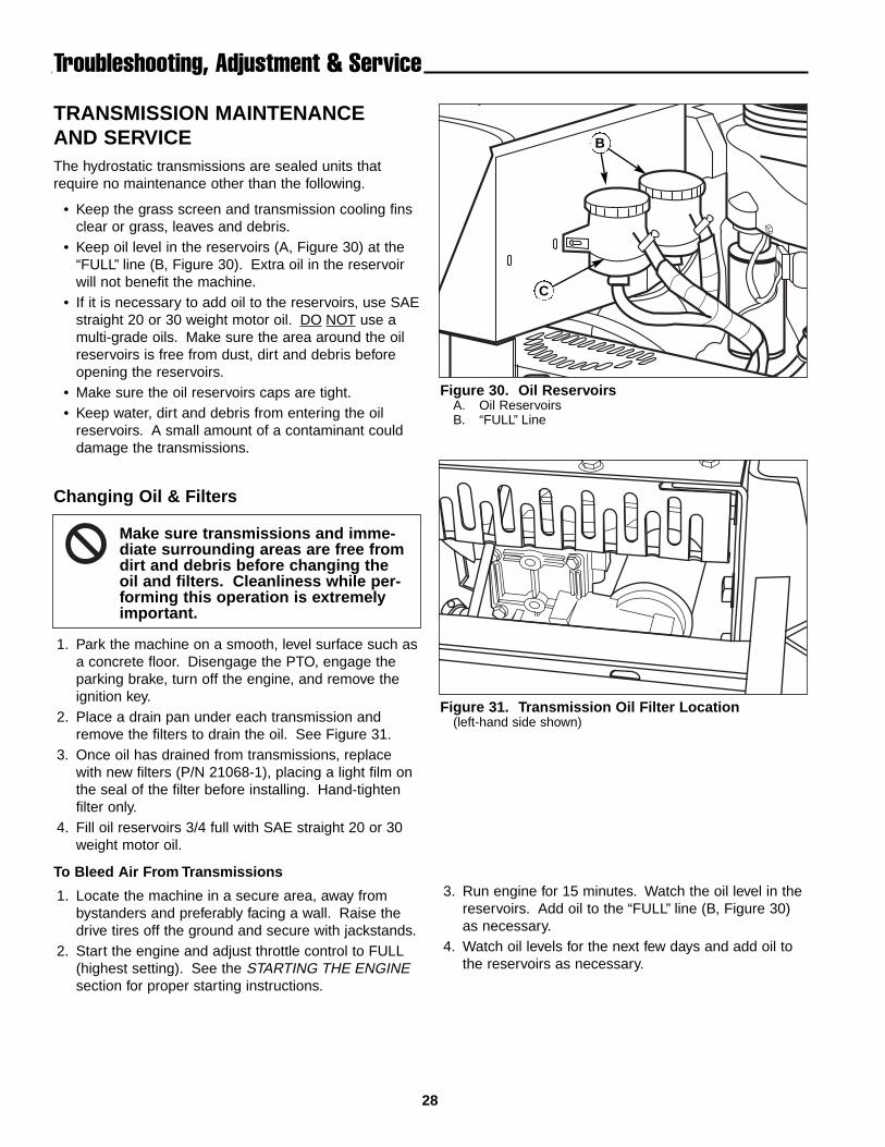
TRANSMISSION MAINTENANCEAND SERVICEThe hydrostatic transmissions are sealed units thatrequire no maintenance other than the following.
• Keep the grass screen and transmission cooling finsclear or grass, leaves and debris.
• Keep oil level in the reservoirs (A, Figure 30) at the“FULL” line (B, Figure 30). Extra oil in the reservoirwill not benefit the machine.
• If it is necessary to add oil to the reservoirs, use SAEstraight 20 or 30 weight motor oil. DO NOT use amulti-grade oils. Make sure the area around the oilreservoirs is free from dust, dirt and debris beforeopening the reservoirs.
• Make sure the oil reservoirs caps are tight.• Keep water, dirt and debris from entering the oil
reservoirs. A small amount of a contaminant coulddamage the transmissions.
Changing Oil & Filters
1. Park the machine on a smooth, level surface such asa concrete floor. Disengage the PTO, engage theparking brake, turn off the engine, and remove theignition key.
2. Place a drain pan under each transmission andremove the filters to drain the oil. See Figure 31.
3. Once oil has drained from transmissions, replacewith new filters (P/N 21068-1), placing a light film onthe seal of the filter before installing. Hand-tightenfilter only.
4. Fill oil reservoirs 3/4 full with SAE straight 20 or 30weight motor oil.
To Bleed Air From Transmissions
1. Locate the machine in a secure area, away frombystanders and preferably facing a wall. Raise thedrive tires off the ground and secure with jackstands.
2. Start the engine and adjust throttle control to FULL(highest setting). See the STARTING THE ENGINEsection for proper starting instructions.
B
C
Figure 30. Oil ReservoirsA. Oil ReservoirsB. “FULL” Line
Figure 31. Transmission Oil Filter Location(left-hand side shown)
Make sure transmissions and imme-diate surrounding areas are free fromdirt and debris before changing theoil and filters. Cleanliness while per-forming this operation is extremelyimportant.
3. Run engine for 15 minutes. Watch the oil level in thereservoirs. Add oil to the “FULL” line (B, Figure 30)as necessary.
4. Watch oil levels for the next few days and add oil tothe reservoirs as necessary.
29
BA
C
AB
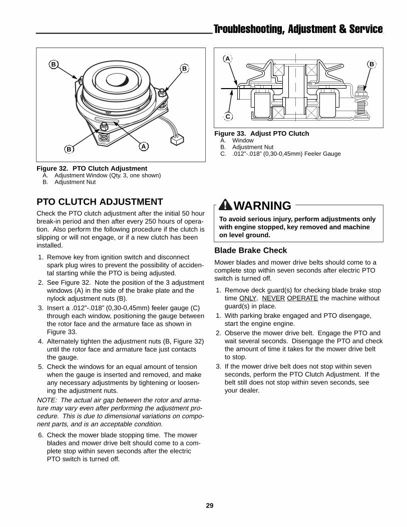
BB
Figure 32. PTO Clutch AdjustmentA. Adjustment Window (Qty. 3, one shown)B. Adjustment Nut
Figure 33. Adjust PTO ClutchA. WindowB. Adjustment NutC. .012”-.018” (0,30-0,45mm) Feeler Gauge
Troubleshooting, Adjustment & Service
WARNINGTo avoid serious injury, perform adjustments onlywith engine stopped, key removed and machineon level ground.
PTO CLUTCH ADJUSTMENTCheck the PTO clutch adjustment after the initial 50 hourbreak-in period and then after every 250 hours of opera-tion. Also perform the following procedure if the clutch isslipping or will not engage, or if a new clutch has beeninstalled.
1. Remove key from ignition switch and disconnectspark plug wires to prevent the possibility of acciden-tal starting while the PTO is being adjusted.
2. See Figure 32. Note the position of the 3 adjustmentwindows (A) in the side of the brake plate and thenylock adjustment nuts (B).
3. Insert a .012”-.018” (0,30-0,45mm) feeler gauge (C)through each window, positioning the gauge betweenthe rotor face and the armature face as shown inFigure 33.
4. Alternately tighten the adjustment nuts (B, Figure 32)until the rotor face and armature face just contactsthe gauge.
5. Check the windows for an equal amount of tensionwhen the gauge is inserted and removed, and makeany necessary adjustments by tightening or loosen-ing the adjustment nuts.
NOTE: The actual air gap between the rotor and arma-ture may vary even after performing the adjustment pro-cedure. This is due to dimensional variations on compo-nent parts, and is an acceptable condition.
6. Check the mower blade stopping time. The mowerblades and mower drive belt should come to a com-plete stop within seven seconds after the electricPTO switch is turned off.
Blade Brake CheckMower blades and mower drive belts should come to acomplete stop within seven seconds after electric PTOswitch is turned off.
1. Remove deck guard(s) for checking blade brake stoptime ONLY. NEVER OPERATE the machine withoutguard(s) in place.
1. With parking brake engaged and PTO disengage,start the engine engine.
2. Observe the mower drive belt. Engage the PTO andwait several seconds. Disengage the PTO and checkthe amount of time it takes for the mower drive beltto stop.
3. If the mower drive belt does not stop within sevenseconds, perform the PTO Clutch Adjustment. If thebelt still does not stop within seven seconds, seeyour dealer.

30
Troubleshooting, Adjustment & Service
BATTERY SERVICE
Checking Battery VoltageA voltmeter can be used to determine condition of bat-tery. When engine is off, the voltmeter shows batteryvoltage, which should be 12 volts. When engine is run-ning, the voltmeter shows voltage of charging circuitwhich normally is 13 to 14 volts.
A dead battery or one too weak to start the engine maynot mean the battery needs to be replaced. For exam-ple, it may mean that the alternator is not charging thebattery properly. If there is any doubt about the cause ofthe problem, see your dealer. If you need to replace thebattery, follow the steps under Cleaning the Battery &Cables in the Regular Maintenance Section.
Charging a Completely Discharged Battery1. Be aware of all the safety precautions you should
observe during the charging operation. If you areunfamiliar with the use of a battery charger andhydrometer, have the battery serviced by your dealer.
2. Add distilled water sufficient to cover the plate (fill tothe proper level near the end of the charge). If thebattery is extremely cold, allow it to warm beforeadding water because the water level will rise as itwarms. Also, an extremely cold battery will notaccept a normal charge until it becomes warm.
3. Always unplug or turn the charger off before attach-ing or removing the clamp connections.
4. Carefully attach the clamps to the battery in properpolarity (usually red to [+] positive and black to [-]negative).
5. While charging, periodically measure the tempera-ture of the electrolyte. If the temperature exceeds125° F (51.6° C), or if violent gassing or spewing ofelectrolyte occurs, the charging rate must be reducedor temporarily halted to prevent battery damage.
6. Charge the battery until fully charged (until the spe-cific gravity of the electrolyte is 1.250 or higher andthe electrolyte temperature is at least 60° F). Thebest method of making certain a battery is fullycharged, but not over charged, is to measure thespecific gravity of a cell once per hour. The batteryis fully charged when the cells are gassing freely atlow charging rate and less than 0.003 change in spe-cific gravity occurs over a three hour period.
WARNINGKeep open flames and sparks away from thebattery; the gasses coming from it are highlyexplosive. Ventilate the battery well duringcharging.
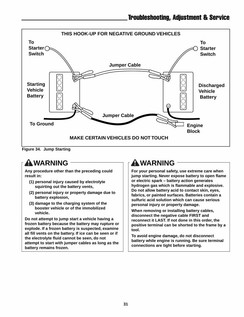
Jump Starting With Auxiliary (Booster)BatteryJump starting is not recommended. However, if it mustbe done, follow these directions. Both booster and dis-charged batteries should be treated carefully when usingjumper cables. Follow the steps below EXACTLY, beingcareful not to cause sparks. Refer to Figure 34.
1. Both batteries must be of the same voltage.2. Position the vehicle with the booster battery adjacent
to the vehicle with the discharged battery so thatbooster cables can be connected easily to the batter-ies in both vehicles. Make certain vehicles do nottouch each other.
3. Wear safety glasses and shield eyes and face frombatteries at all times. Be sure vent caps are tight.Place damp cloth over vent caps on both batteries.
4. Connect positive (+) cable to positive post of dis-charged battery (wired to starter or solenoid).
5. Connect the other end of same cable to same postmarked positive (+) on booster battery.
6. Connect the second cable negative (-) to other postof booster battery.
7. Make final connection on engine block of stalledvehicle away from battery. Do not lean over batter-ies.
8. Start the engine of the vehicle with the booster bat-tery. Wait a few minutes, then attempt to start theengine of the vehicle with the discharged battery.
9. If the vehicle does not start after cranking for thirtyseconds, STOP PROCEDURE. More than thirty sec-onds seldom starts the engine unless some mechan-ical adjustment is made.
10. After starting, allow the engine to return to idlespeed. Remove the cable connection at the engineor frame. Then remove the other end of the samecable from the booster battery.
11. Remove the other cable by disconnecting at the dis-charged battery first and then disconnect the oppo-site end from the booster battery.
12. Discard the damp cloths that were placed over thebattery vent caps.
31
To StarterSwitch
StartingVehicleBattery
To Ground
To Starter Switch
DischargedVehicle Battery
EngineBlock
THIS HOOK-UP FOR NEGATIVE GROUND VEHICLES
MAKE CERTAIN VEHICLES DO NOT TOUCH
Jumper Cable
Jumper Cable
WARNINGAny procedure other than the preceding couldresult in:
(1) personal injury caused by electrolytesquirting out the battery vents,
(2) personal injury or property damage due tobattery explosion,
(3) damage to the charging system of thebooster vehicle or of the immobilizedvehicle.
Do not attempt to jump start a vehicle having afrozen battery because the battery may rupture orexplode. If a frozen battery is suspected, examineall fill vents on the battery. If ice can be seen or ifthe electrolyte fluid cannot be seen, do notattempt to start with jumper cables as long as thebattery remains frozen.
WARNINGFor your personal safety, use extreme care whenjump starting. Never expose battery to open flameor electric spark – battery action generateshydrogen gas which is flammable and explosive.Do not allow battery acid to contact skin, eyes,fabrics, or painted surfaces. Batteries contain asulfuric acid solution which can cause seriouspersonal injury or property damage.
When removing or installing battery cables,disconnect the negative cable FIRST andreconnect it LAST. If not done in this order, thepositive terminal can be shorted to the frame by atool.
To avoid engine damage, do not disconnectbattery while engine is running. Be sure terminalconnections are tight before starting.
Figure 34. Jump Starting
Troubleshooting, Adjustment & Service
32
Common Replacement Parts & Accessories
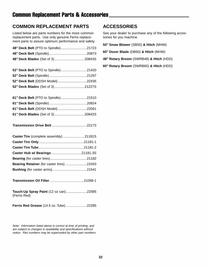
COMMON REPLACEMENT PARTSListed below are parts numbers for the more commonreplacement parts. Use only genuine Ferris replace-ment parts to assure optimum performance and safety.
48” Deck Belt (PTO to Spindle)............................21723
48” Deck Belt (Spindle) ........................................20873
48” Deck Blades (Set of 3) ................................20843S
52” Deck Belt (PTO to Spindle)............................21420
52” Deck Belt (Spindle) ........................................21297
52” Deck Belt (DDSH Model) ...............................22435
52” Deck Blades (Set of 3) ................................21227S
61” Deck Belt (PTO to Spindle)............................21510
61” Deck Belt (Spindle) ........................................20824
61” Deck Belt (DDSH Model) ...............................22061
61” Deck Blades (Set of 3) ................................20842S
Transmission Drive Belt .....................................22173
Caster Tire (complete assembly) .......................21181S
Caster Tire Only................................................21181-1
Caster Tire Tube ................................................21181-2
Caster Hub w/ Bearings ................................21181-3S
Bearing (for caster tires).......................................21182
Bearing Retainer (for caster tires) .......................21043
Bushing (for caster arms).....................................21541
Transmission Oil Filter ....................................21068-1
Touch-Up Spray Paint (12 oz can) ......................22585(Ferris Red)
Ferris Red Grease (14.5 oz. Tube) ......................22285
ACCESSORIESSee your dealer to purchase any of the following acces-sories for you machine.
50” Snow Blower (SB50) & Hitch (MHW)
60” Dozer Blade (DB60) & Hitch (MHW)
48” Rotary Broom (SWRB48) & Hitch (HDD)
60” Rotary Broom (SWRB60) & Hitch (HDD)
Note: Information listed above is correct at time of printing, andare subject to changes in availability and specifications withoutnotice. Part numbers may be superceded by other part numbers.
Lawn Care& Mowing Information
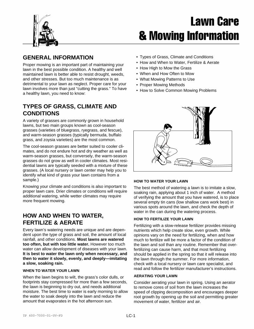
TYPES OF GRASS, CLIMATE ANDCONDITIONSA variety of grasses are commonly grown in householdlawns, but two main groups known as cool-seasongrasses (varieties of bluegrass, ryegrass, and fescue),and warm-season grasses (typically bermuda, buffalograss, and zoysia varieties) are the most common.
The cool-season grasses are better suited to cooler cli-mates, and do not endure hot and dry weather as well aswarm-season grasses, but conversely, the warm-seasongrasses do not grow as well in cooler climates. Most resi-dential lawns are typically seeded with a mixture of thesegrasses. (A local nursery or lawn center may help you toidentify what kind of grass your lawn contains from asample.)
Knowing your climate and conditions is also important toproper lawn care. Drier climates or conditions will requireadditional watering, while wetter climates may requiremore frequent mowing.
HOW AND WHEN TO WATER,FERTILIZE & AERATEEvery lawn’s watering needs are unique and are depen-dent upon the type of grass and soil, the amount of localrainfall, and other conditions. Most lawns are wateredtoo often, but with too little water. However too muchwater can allow development of diseases with your lawn.It is best to water the lawn only when necessary, andthen to water it slowly, evenly, and deeply—imitatinga slow, soaking rain.
WHEN TO WATER YOUR LAWN
When the lawn begins to wilt, the grass’s color dulls, orfootprints stay compressed for more than a few seconds,the lawn is beginning to dry out, and needs additionalmoisture. The best time to water is early morning to allowthe water to soak deeply into the lawn and reduce theamount that evaporates in the hot afternoon sun.
LC-1
HOW TO WATER YOUR LAWN
The best method of watering a lawn is to imitate a slow,soaking rain, applying about 1 inch of water. A methodof verifying the amount that you have watered, is to placeseveral empty tin cans (low shallow cans work best) invarious spots around the lawn, and check the depth ofwater in the can during the watering process.
HOW TO FERTILIZE YOUR LAWN
Fertilizing with a slow-release fertilizer provides missingnutrients which help create slow, even growth. Whileopinions vary on the need for fertilizing, when and howmuch to fertilize will be more a factor of the condition ofthe lawn and soil than any routine. Remember that over-fertilizing can cause harm, and that most fertilizingshould be applied in the spring so that it will release intothe lawn through the summer. For more information,check with a local nursery or lawn care specialist, andread and follow the fertilizer manufacturer’s instructions.
AERATING YOUR LAWN
Consider aerating your lawn in spring. Using an aeratorto remove cores of soil from the lawn increases thespeed of clipping decomposition and encourages deeperroot growth by opening up the soil and permitting greatermovement of water, fertilizer and air.
GENERAL INFORMATIONProper mowing is an important part of maintaining yourlawn in the best possible condition. A healthy and wellmaintained lawn is better able to resist drought, weeds,and other stresses. But too much maintenance is asdetrimental to your lawn as neglect. Proper care for yourlawn involves more than just “cutting the grass.” To havea healthy lawn, you need to know:
• Types of Grass, Climate and Conditions• How and When to Water, Fertilize & Aerate• How High to Mow the Grass• When and How Often to Mow• What Mowing Patterns to Use• Proper Mowing Methods• How to Solve Common Mowing Problems
TP 600-7000-01-UV-FD
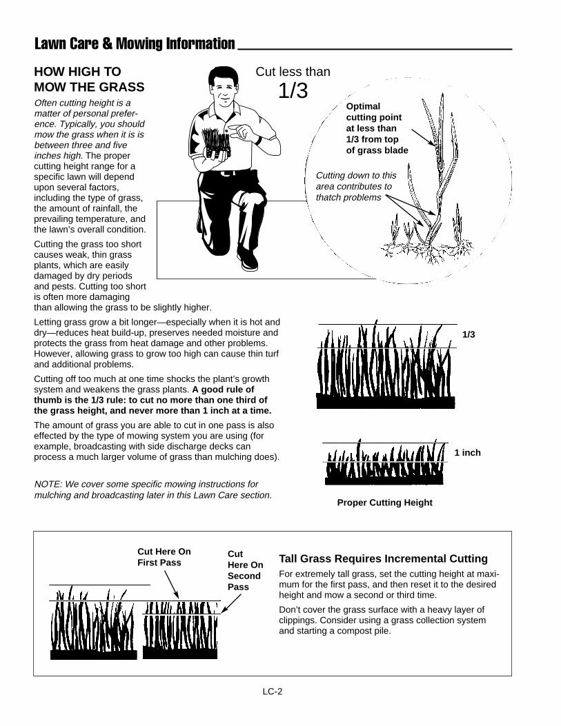
LC-2
Lawn Care & Mowing Information
HOW HIGH TOMOW THE GRASSOften cutting height is amatter of personal prefer-ence. Typically, you shouldmow the grass when it is isbetween three and fiveinches high. The propercutting height range for aspecific lawn will dependupon several factors,including the type of grass,the amount of rainfall, theprevailing temperature, andthe lawn’s overall condition.
Cutting the grass too shortcauses weak, thin grassplants, which are easilydamaged by dry periodsand pests. Cutting too shortis often more damagingthan allowing the grass to be slightly higher.
Letting grass grow a bit longer—especially when it is hot anddry—reduces heat build-up, preserves needed moisture andprotects the grass from heat damage and other problems.However, allowing grass to grow too high can cause thin turfand additional problems.
Cutting off too much at one time shocks the plant’s growthsystem and weakens the grass plants. A good rule ofthumb is the 1/3 rule: to cut no more than one third ofthe grass height, and never more than 1 inch at a time.
The amount of grass you are able to cut in one pass is alsoeffected by the type of mowing system you are using (forexample, broadcasting with side discharge decks canprocess a much larger volume of grass than mulching does).
NOTE: We cover some specific mowing instructions formulching and broadcasting later in this Lawn Care section.
Proper Cutting Height
CutHere OnSecondPass
Cut Here OnFirst Pass
Optimal cutting pointat less than 1/3 from topof grass blade
Tall Grass Requires Incremental CuttingFor extremely tall grass, set the cutting height at maxi-mum for the first pass, and then reset it to the desiredheight and mow a second or third time.
Don’t cover the grass surface with a heavy layer ofclippings. Consider using a grass collection systemand starting a compost pile.
Cutting down to thisarea contributes tothatch problems
Cut less than
1/3
1 inch
1/3
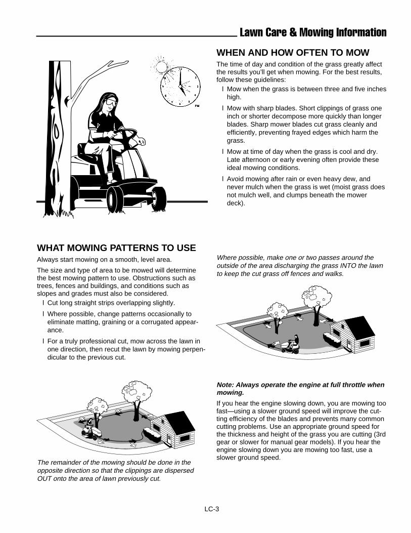
LC-3
Lawn Care & Mowing Information
Where possible, make one or two passes around theoutside of the area discharging the grass INTO the lawnto keep the cut grass off fences and walks.
WHEN AND HOW OFTEN TO MOWThe time of day and condition of the grass greatly affectthe results you’ll get when mowing. For the best results,follow these guidelines:
l Mow when the grass is between three and five incheshigh.
l Mow with sharp blades. Short clippings of grass oneinch or shorter decompose more quickly than longerblades. Sharp mower blades cut grass cleanly andefficiently, preventing frayed edges which harm thegrass.
l Mow at time of day when the grass is cool and dry.Late afternoon or early evening often provide theseideal mowing conditions.
l Avoid mowing after rain or even heavy dew, andnever mulch when the grass is wet (moist grass doesnot mulch well, and clumps beneath the mowerdeck).
WHAT MOWING PATTERNS TO USEAlways start mowing on a smooth, level area.
The size and type of area to be mowed will determinethe best mowing pattern to use. Obstructions such astrees, fences and buildings, and conditions such asslopes and grades must also be considered.
l Cut long straight strips overlapping slightly.
l Where possible, change patterns occasionally toeliminate matting, graining or a corrugated appear-ance.
l For a truly professional cut, mow across the lawn inone direction, then recut the lawn by mowing perpen-dicular to the previous cut.
The remainder of the mowing should be done in theopposite direction so that the clippings are dispersedOUT onto the area of lawn previously cut.
Note: Always operate the engine at full throttle whenmowing.
If you hear the engine slowing down, you are mowing toofast—using a slower ground speed will improve the cut-ting efficiency of the blades and prevents many commoncutting problems. Use an appropriate ground speed forthe thickness and height of the grass you are cutting (3rdgear or slower for manual gear models). If you hear theengine slowing down you are mowing too fast, use aslower ground speed.
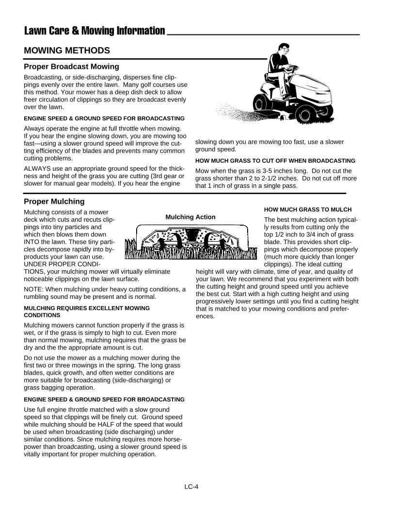
LC-4
Lawn Care & Mowing Information
MOWING METHODS
Proper Broadcast MowingBroadcasting, or side-discharging, disperses fine clip-pings evenly over the entire lawn. Many golf courses usethis method. Your mower has a deep dish deck to allowfreer circulation of clippings so they are broadcast evenlyover the lawn.
ENGINE SPEED & GROUND SPEED FOR BROADCASTING
Always operate the engine at full throttle when mowing.If you hear the engine slowing down, you are mowing toofast—using a slower ground speed will improve the cut-ting efficiency of the blades and prevents many commoncutting problems.
ALWAYS use an appropriate ground speed for the thick-ness and height of the grass you are cutting (3rd gear orslower for manual gear models). If you hear the engine
slowing down you are mowing too fast, use a slowerground speed.
HOW MUCH GRASS TO CUT OFF WHEN BROADCASTING
Mow when the grass is 3-5 inches long. Do not cut thegrass shorter than 2 to 2-1/2 inches. Do not cut off morethat 1 inch of grass in a single pass.
Proper MulchingMulching consists of a mowerdeck which cuts and recuts clip-pings into tiny particles andwhich then blows them downINTO the lawn. These tiny parti-cles decompose rapidly into by-products your lawn can use.UNDER PROPER CONDI-TIONS, your mulching mower will virtually eliminatenoticeable clippings on the lawn surface.
NOTE: When mulching under heavy cutting conditions, arumbling sound may be present and is normal.
MULCHING REQUIRES EXCELLENT MOWINGCONDITIONS
Mulching mowers cannot function properly if the grass iswet, or if the grass is simply to high to cut. Even morethan normal mowing, mulching requires that the grass bedry and the the appropriate amount is cut.
Do not use the mower as a mulching mower during thefirst two or three mowings in the spring. The long grassblades, quick growth, and often wetter conditions aremore suitable for broadcasting (side-discharging) orgrass bagging operation.
ENGINE SPEED & GROUND SPEED FOR BROADCASTING
Use full engine throttle matched with a slow groundspeed so that clippings will be finely cut. Ground speedwhile mulching should be HALF of the speed that wouldbe used when broadcasting (side discharging) undersimilar conditions. Since mulching requires more horse-power than broadcasting, using a slower ground speed isvitally important for proper mulching operation.
HOW MUCH GRASS TO MULCH
The best mulching action typical-ly results from cutting only thetop 1/2 inch to 3/4 inch of grassblade. This provides short clip-pings which decompose properly(much more quickly than longerclippings). The ideal cutting
height will vary with climate, time of year, and quality ofyour lawn. We recommend that you experiment with boththe cutting height and ground speed until you achievethe best cut. Start with a high cutting height and usingprogressively lower settings until you find a cutting heightthat is matched to your mowing conditions and prefer-ences.
Mulching Action
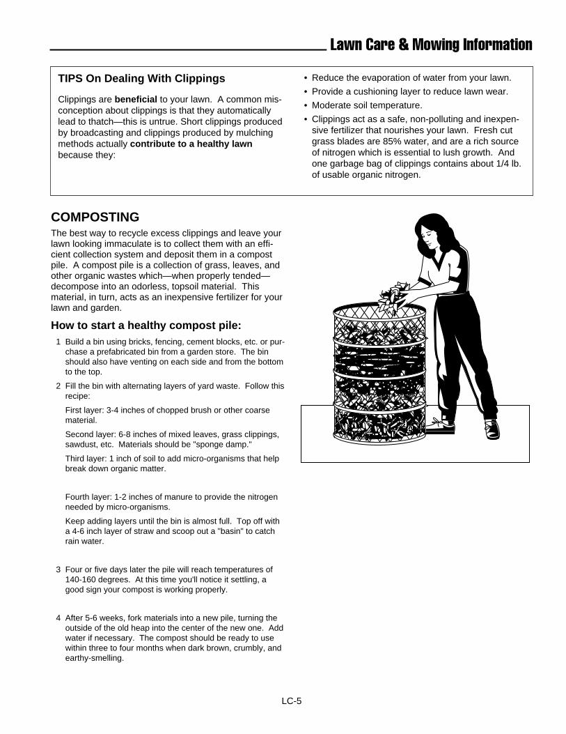
LC-5
Lawn Care & Mowing Information
TIPS On Dealing With Clippings
Clippings are beneficial to your lawn. A common mis-conception about clippings is that they automaticallylead to thatch—this is untrue. Short clippings producedby broadcasting and clippings produced by mulchingmethods actually contribute to a healthy lawnbecause they:
• Reduce the evaporation of water from your lawn.
• Provide a cushioning layer to reduce lawn wear.
• Moderate soil temperature.
• Clippings act as a safe, non-polluting and inexpen-sive fertilizer that nourishes your lawn. Fresh cutgrass blades are 85% water, and are a rich sourceof nitrogen which is essential to lush growth. Andone garbage bag of clippings contains about 1/4 lb.of usable organic nitrogen.
COMPOSTING The best way to recycle excess clippings and leave yourlawn looking immaculate is to collect them with an effi-cient collection system and deposit them in a compostpile. A compost pile is a collection of grass, leaves, andother organic wastes which—when properly tended—decompose into an odorless, topsoil material. Thismaterial, in turn, acts as an inexpensive fertilizer for yourlawn and garden.
How to start a healthy compost pile:1 Build a bin using bricks, fencing, cement blocks, etc. or pur-
chase a prefabricated bin from a garden store. The binshould also have venting on each side and from the bottomto the top.
2 Fill the bin with alternating layers of yard waste. Follow thisrecipe:
First layer: 3-4 inches of chopped brush or other coarsematerial.
Second layer: 6-8 inches of mixed leaves, grass clippings,sawdust, etc. Materials should be "sponge damp."
Third layer: 1 inch of soil to add micro-organisms that helpbreak down organic matter.
Fourth layer: 1-2 inches of manure to provide the nitrogenneeded by micro-organisms.
Keep adding layers until the bin is almost full. Top off witha 4-6 inch layer of straw and scoop out a "basin" to catchrain water.
3 Four or five days later the pile will reach temperatures of140-160 degrees. At this time you'll notice it settling, agood sign your compost is working properly.
4 After 5-6 weeks, fork materials into a new pile, turning theoutside of the old heap into the center of the new one. Addwater if necessary. The compost should be ready to usewithin three to four months when dark brown, crumbly, andearthy-smelling.
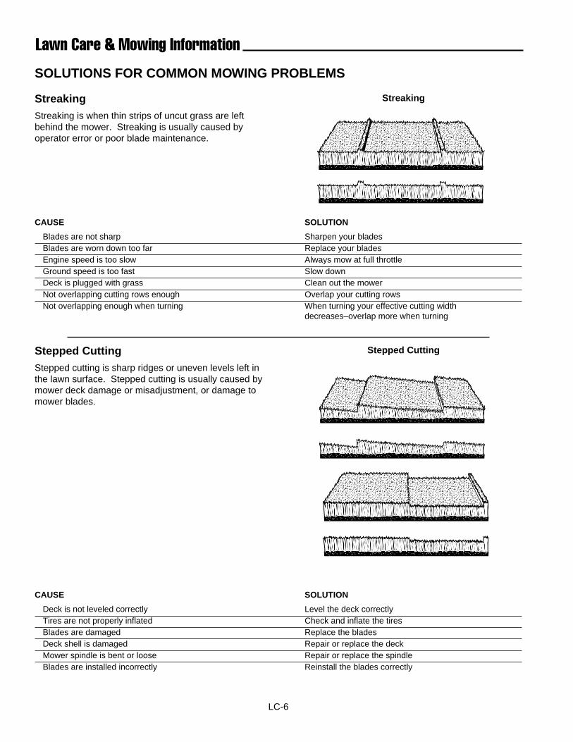
LC-6
Lawn Care & Mowing Information
Stepped CuttingStepped cutting is sharp ridges or uneven levels left inthe lawn surface. Stepped cutting is usually caused bymower deck damage or misadjustment, or damage tomower blades.
CAUSE SOLUTION
Deck is not leveled correctly Level the deck correctlyTires are not properly inflated Check and inflate the tiresBlades are damaged Replace the bladesDeck shell is damaged Repair or replace the deckMower spindle is bent or loose Repair or replace the spindleBlades are installed incorrectly Reinstall the blades correctly
���������������������
����������
����
��������
���������������
Stepped Cutting
StreakingStreakingStreaking is when thin strips of uncut grass are leftbehind the mower. Streaking is usually caused byoperator error or poor blade maintenance.
CAUSE SOLUTION
Blades are not sharp Sharpen your bladesBlades are worn down too far Replace your bladesEngine speed is too slow Always mow at full throttleGround speed is too fast Slow downDeck is plugged with grass Clean out the mowerNot overlapping cutting rows enough Overlap your cutting rowsNot overlapping enough when turning When turning your effective cutting width
decreases–overlap more when turning
���������������������������
���
������
SOLUTIONS FOR COMMON MOWING PROBLEMS
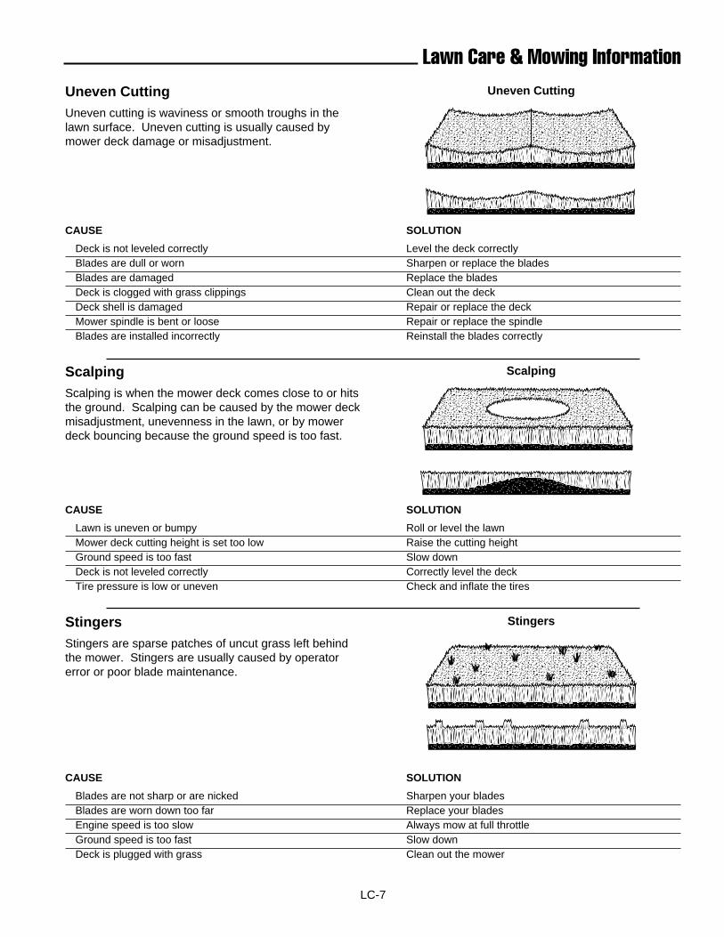
LC-7
Lawn Care & Mowing Information
StingersStingers are sparse patches of uncut grass left behindthe mower. Stingers are usually caused by operatorerror or poor blade maintenance.
CAUSE SOLUTION
Blades are not sharp or are nicked Sharpen your bladesBlades are worn down too far Replace your bladesEngine speed is too slow Always mow at full throttleGround speed is too fast Slow down Deck is plugged with grass Clean out the mower
���������������������������
Uneven CuttingUneven cutting is waviness or smooth troughs in thelawn surface. Uneven cutting is usually caused bymower deck damage or misadjustment.
CAUSE SOLUTION
Deck is not leveled correctly Level the deck correctlyBlades are dull or worn Sharpen or replace the bladesBlades are damaged Replace the bladesDeck is clogged with grass clippings Clean out the deckDeck shell is damaged Repair or replace the deckMower spindle is bent or loose Repair or replace the spindleBlades are installed incorrectly Reinstall the blades correctly
���������������
���������������
ScalpingScalping is when the mower deck comes close to or hitsthe ground. Scalping can be caused by the mower deckmisadjustment, unevenness in the lawn, or by mowerdeck bouncing because the ground speed is too fast.
CAUSE SOLUTION
Lawn is uneven or bumpy Roll or level the lawnMower deck cutting height is set too low Raise the cutting heightGround speed is too fast Slow downDeck is not leveled correctly Correctly level the deckTire pressure is low or uneven Check and inflate the tires
���������������������������
Uneven Cutting
Scalping
Stingers
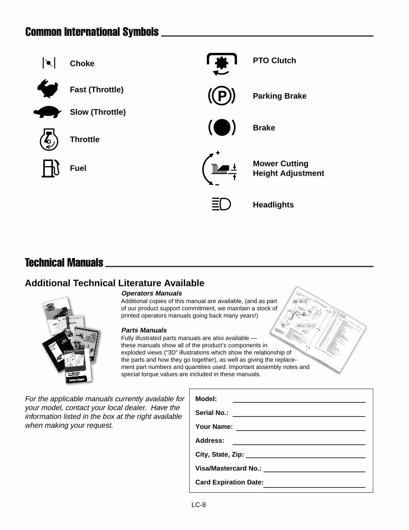
LC-8
Common International Symbols
Technical Manuals
Additional Technical Literature AvailableOperators ManualsAdditional copies of this manual are available, (and as partof our product support commitment, we maintain a stock ofprinted operators manuals going back many years!)
Parts ManualsFully illustrated parts manuals are also available —these manuals show all of the product’s components inexploded views (“3D” illustrations which show the relationship ofthe parts and how they go together), as well as giving the replace-ment part numbers and quantities used. Important assembly notes andspecial torque values are included in these manuals.
For the applicable manuals currently available foryour model, contact your local dealer. Have theinformation listed in the box at the right availablewhen making your request.
Model:
Serial No.:
Your Name:
Address:
City, State, Zip:
Visa/Mastercard No.:
Card Expiration Date:
Choke
Fast (Throttle)
Slow (Throttle)
Throttle
Fuel
PTO Clutch
Parking Brake
Brake
Headlights
Mower CuttingHeight Adjustment

LC-9
Notes