feeder protection system - ge grid solutions · ge multilin 350 feeder protection system...
TRANSCRIPT

GE Multilin's Quality Management System is
registered to ISO9001:2000
QMI # 005094
GE Digital EnergyMultilin
GE Multilin
215 Anderson Avenue, Markham, Ontario
Canada L6E 1B3
Tel: (905) 294-6222 Fax: (905) 201-2098
Internet: http://www.GEmultilin.com
Instruction manual350 revision: 1.41
Manual P/N: 1601-9086-A8
GE publication code: GEK-113507G
Copyright © 2011 GE Multilin
*1601-9086-A8*
350Feeder Protection System
Feeder protection and control

© 2011 GE Multilin Incorporated. All rights reserved.
GE Multilin 350 Feeder Protection System instruction manual for revision 1.41.
350 Feeder Protection System, EnerVista, EnerVista Launchpad, and EnerVista SR3 Setup are registered trademarks of GE Multilin Inc.
The contents of this manual are the property of GE Multilin Inc. This documentation is furnished on license and may not be reproduced in whole or in part without the permission of GE Multilin. The content of this manual is for informational use only and is subject to change without notice.
Part number: 1601-9086-A8 (May 2011)
350C FEEDER PROTECTION SYSTEM – INSTRUCTION MANUAL
Table of Contents
1. INTRODUCTION Overview ................................................................................................................................1 - 1Cautions and warnings ...................................................................................................1 - 2Description of the 350 Feeder Protection System..............................................1 - 3350 order codes..................................................................................................................1 - 6Specifications.......................................................................................................................1 - 7
Password security....................................................................................................................1 - 7Protection.....................................................................................................................................1 - 7Metering........................................................................................................................................1 - 9Data capture ..............................................................................................................................1 - 10Control ...........................................................................................................................................1 - 10Inputs .............................................................................................................................................1 - 11Outputs..........................................................................................................................................1 - 12Power supply ..............................................................................................................................1 - 13Communications ......................................................................................................................1 - 13Testing and certification .......................................................................................................1 - 14Physical .........................................................................................................................................1 - 15Environmental............................................................................................................................1 - 15
2. INSTALLATION Mechanical installation ...................................................................................................2 - 1Dimensions..................................................................................................................................2 - 1Product identification .............................................................................................................2 - 2Mounting ......................................................................................................................................2 - 3Unit withdrawal and insertion............................................................................................2 - 5
Electrical installation ........................................................................................................2 - 7Terminal identification ...........................................................................................................2 - 8Phase sequence and transformer polarity...................................................................2 - 10Current inputs ............................................................................................................................2 - 11Ground and sensitive ground CT inputs ........................................................................2 - 11Zero sequence CT installation ............................................................................................2 - 12Voltage inputs ............................................................................................................................2 - 13Control power ............................................................................................................................2 - 13Contact inputs ...........................................................................................................................2 - 14Trip and Close output relays ...............................................................................................2 - 15Serial communications ..........................................................................................................2 - 17IRIG-B .............................................................................................................................................2 - 18
3. INTERFACES Front control panel interface........................................................................................3 - 2Description ..................................................................................................................................3 - 2Display ...........................................................................................................................................3 - 3
Working with the Keypad....................................................................................................3 - 3LED status indicators..............................................................................................................3 - 4Relay messages ........................................................................................................................3 - 5
Target messages.....................................................................................................................3 - 5Self-test errors..........................................................................................................................3 - 6Flash messages .......................................................................................................................3 - 7
Software setup ....................................................................................................................3 - 9Quick setup - Software interface ......................................................................................3 - 9EnerVista SR3 Setup Software............................................................................................3 - 9
Hardware and software requirements.........................................................................3 - 10
350C FEEDER PROTECTION SYSTEM – INSTRUCTION MANUAL
Installing the EnerVista SR3 Setup software ..............................................................3 - 10Connecting EnerVista SR3 Setup to the relay ............................................................3 - 13
Configuring serial communications...............................................................................3 - 13Using the Quick Connect feature ....................................................................................3 - 14Configuring Ethernet communications ........................................................................3 - 15Connecting to the relay........................................................................................................3 - 16
Working with setpoints and setpoint files ....................................................................3 - 17Engaging a device ..................................................................................................................3 - 17Entering setpoints...................................................................................................................3 - 17File support ................................................................................................................................3 - 19Using setpoints files...............................................................................................................3 - 19Downloading and saving setpoints files ......................................................................3 - 19Adding setpoints files to the environment ..................................................................3 - 19Creating a new setpoint file ...............................................................................................3 - 20Upgrading setpoint files to a new revision .................................................................3 - 21Printing setpoints and actual values .............................................................................3 - 22Printing actual values from a connected device .....................................................3 - 23Loading setpoints from a file.............................................................................................3 - 24
Upgrading relay firmware ...................................................................................................3 - 24Loading new relay firmware..............................................................................................3 - 24
Advanced EnerVista SR3 Setup features ......................................................................3 - 27Flexcurve editor .......................................................................................................................3 - 27Transient recorder (Waveform capture).......................................................................3 - 28Protection summary..............................................................................................................3 - 31Password security ..................................................................................................................3 - 32
4. ACTUAL VALUES Actual values overview ...................................................................................................4 - 1A1 Status................................................................................................................................4 - 3
Clock...............................................................................................................................................4 - 3Contact inputs ...........................................................................................................................4 - 4Output relays .............................................................................................................................4 - 4Logic elements ..........................................................................................................................4 - 4Virtual inputs ..............................................................................................................................4 - 5Remote inputs ...........................................................................................................................4 - 5Remote outputs ........................................................................................................................4 - 5Contact inputs summary......................................................................................................4 - 5Output relays summary ........................................................................................................4 - 5Logic elements summary.....................................................................................................4 - 6GOOSE status.............................................................................................................................4 - 6GOOSE HDR status ..................................................................................................................4 - 6
A2 Metering ..........................................................................................................................4 - 7Current ..........................................................................................................................................4 - 7Voltage..........................................................................................................................................4 - 8Power.............................................................................................................................................4 - 8Energy ...........................................................................................................................................4 - 9Thermal capacity .....................................................................................................................4 - 9Clear energy ...............................................................................................................................4 - 9
A3 Records............................................................................................................................4 - 10Event records.............................................................................................................................4 - 10Transient records .....................................................................................................................4 - 28Clear event record...................................................................................................................4 - 28Clear transient record............................................................................................................4 - 28Clear thermal capacity record...........................................................................................4 - 28
A4 Target messages.........................................................................................................4 - 29
350C FEEDER PROTECTION SYSTEM – INSTRUCTION MANUAL
5. QUICK SETUP - FRONT CONTROL PANEL
Quick Setup settings.........................................................................................................5 - 3
6. SETPOINTS Setpoints Main Menu........................................................................................................6 - 1Setpoint entry methods.........................................................................................................6 - 2Common setpoints ..................................................................................................................6 - 3Logic diagrams..........................................................................................................................6 - 4Setting text abbreviations ....................................................................................................6 - 4
S1 Relay setup .....................................................................................................................6 - 6Clock ...............................................................................................................................................6 - 6Password security....................................................................................................................6 - 8
Access passwords ..................................................................................................................6 - 9Communications ......................................................................................................................6 - 11
RS485 interface .......................................................................................................................6 - 11Ethernet.......................................................................................................................................6 - 12Modbus........................................................................................................................................6 - 12IEC 60870-5-103 serial communication ......................................................................6 - 14IEC60870-5-104 protocol....................................................................................................6 - 29DNP communication .............................................................................................................6 - 30IEC 61850 GOOSE communications...............................................................................6 - 44
Event recorder ...........................................................................................................................6 - 45Transient recorder ...................................................................................................................6 - 46Front panel ..................................................................................................................................6 - 47Installation ...................................................................................................................................6 - 48
S2 System Setup.................................................................................................................6 - 49Current sensing .........................................................................................................................6 - 49Voltage sensing.........................................................................................................................6 - 50Power system.............................................................................................................................6 - 51Breaker ..........................................................................................................................................6 - 51User curve....................................................................................................................................6 - 52FlexCurves™ ...............................................................................................................................6 - 52
S3 Protection........................................................................................................................6 - 53Current elements......................................................................................................................6 - 55
TOC curves .................................................................................................................................6 - 56Phase timed overcurrent protection .............................................................................6 - 63Phase instantaneous overcurrent protection ...........................................................6 - 66Ground/Sensitive Ground timed overcurrent protection.....................................6 - 68Ground/Sensitive Ground instantaneous overcurrent protection...................6 - 71Ground directional .................................................................................................................6 - 73Neutral timed overcurrent protection...........................................................................6 - 78Neutral instantaneous overcurrent protection ........................................................6 - 81Neutral directional..................................................................................................................6 - 84Negative sequence instantaneous overcurrent protection ...............................6 - 88
Voltage elements......................................................................................................................6 - 90Phase undervoltage ..............................................................................................................6 - 90Phase overvoltage..................................................................................................................6 - 94Neutral overvoltage...............................................................................................................6 - 96Negative sequence overvoltage......................................................................................6 - 98Auxiliary undervoltage .........................................................................................................6 - 100Auxiliary overvoltage.............................................................................................................6 - 103Underfrequency.......................................................................................................................6 - 105Overfrequency..........................................................................................................................6 - 108
Cable Thermal Model..............................................................................................................6 - 110
350C FEEDER PROTECTION SYSTEM – INSTRUCTION MANUAL
S4 Controls............................................................................................................................6 - 114Change setpoint group .........................................................................................................6 - 115Virtual inputs ..............................................................................................................................6 - 117Logic elements ..........................................................................................................................6 - 118Breaker control .........................................................................................................................6 - 124Cold load pickup.......................................................................................................................6 - 125Breaker failure ...........................................................................................................................6 - 128Autorecloser ...............................................................................................................................6 - 130
S5 Inputs/Outputs .............................................................................................................6 - 135Contact inputs ...........................................................................................................................6 - 135Output relays .............................................................................................................................6 - 136
Output Relay 1 "Trip" .............................................................................................................6 - 137Output Relay 2 "Close"..........................................................................................................6 - 139Auxiliary Output Relays 3 to 6...........................................................................................6 - 141Critical Failure Relay #7 .......................................................................................................6 - 142
Virtual inputs ..............................................................................................................................6 - 143Remote inputs ...........................................................................................................................6 - 145
7. MAINTENANCE M1 Relay information.......................................................................................................7 - 3M3 Breaker maintenance ..............................................................................................7 - 4
Trip coil..........................................................................................................................................7 - 4Close coil ......................................................................................................................................7 - 6Breaker trip counter................................................................................................................7 - 9
M4 Breaker monitor..........................................................................................................7 - 12M5 Relay maintenance ...................................................................................................7 - 13
Ambient temperature ............................................................................................................ 7 - 13
APPENDIX. Change notes ............................................................................................................... Appendix - 1Manual Revision history................................................................................................ Appendix - 1

350 FEEDER PROTECTION SYSTEM – INSTRUCTION MANUAL 1–1
350 Feeder Protection System
Chapter 1: Introduction
Digital EnergyMultilin
Introduction
Overview
The 350 is a microprocessor-based relay for primary and backup over-current protection of medium and low voltage distribution feeders. The relay is also suitable for providing over-current protection for small and medium size motors, transformers, generators, and distribution bus-bars. The small footprint and the withdrawable option make the 350 relay ideal for panel mounting on either new or retrofit installations. The combination of proven hardware, a variety of protection and control features, and communications, makes the relay ideal for total feeder protection and control. Equipped with serial (RS485), USB, and Ethernet ports, and a wide selection of protocols such as Modbus, DNP3.0, IEC 60870-5-103, 60870-5-104, GOOSE, the 350 relay is the best-in-class for MCCs, SCADA and inter-relay communications. The 350 relay provides excellent transparency with respect to power system conditions and events, through its four-line 20-character display, as well as the EnerVista SR3 Setup program. Conveniently located LEDs provide indication of relay operation, alarm, and pickup, as well as breaker, and relay status.The 350 relay provides the following key benefits:• Withdrawable small footprint – saves on rewiring and space.• Multiple protection groups with the added flexibility of switching through a wide
selection of overcurrent protection and control features. • Fast setup (Quick Setup) menu for power-system setup and a simple overcurrent
protection configuration.• Large four-line LCD display, LEDs, and an easy-to-navigate keypad.• Multiple communication protocols for simultaneous access when integrated into
monitoring and control systems.
1–2 350 FEEDER PROTECTION SYSTEM – INSTRUCTION MANUAL
CAUTIONS AND WARNINGS CHAPTER 1: INTRODUCTION
Cautions and warnings
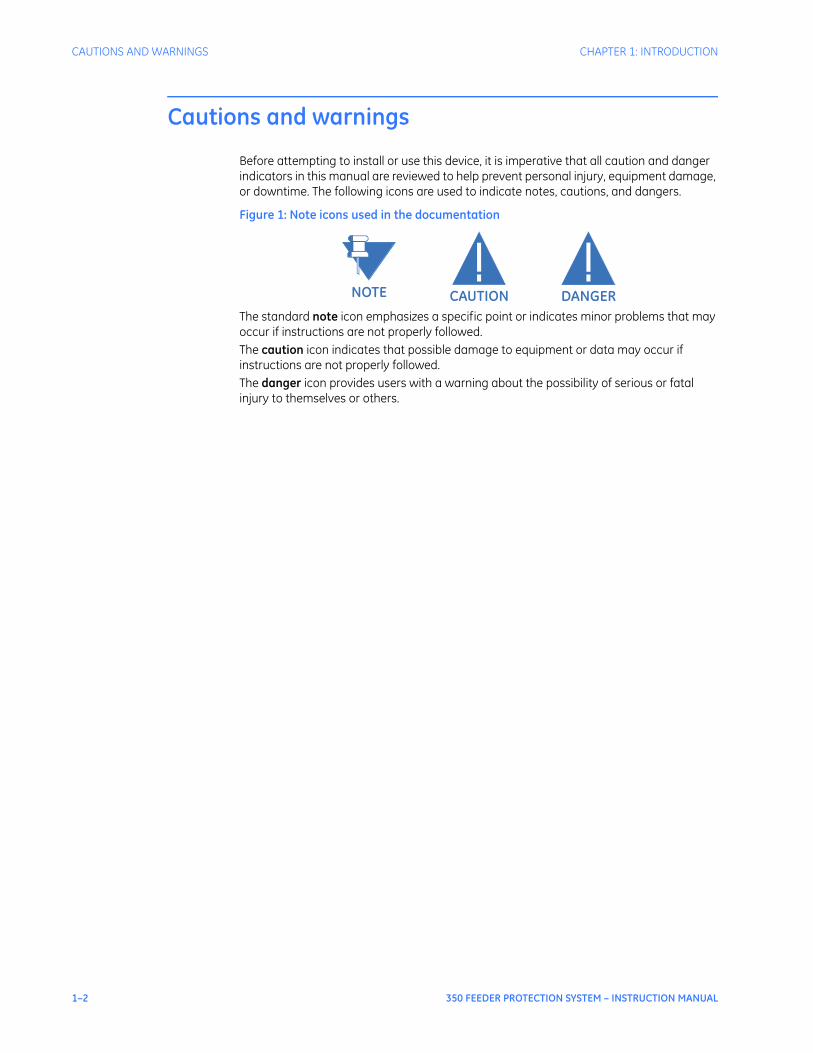
Before attempting to install or use this device, it is imperative that all caution and danger indicators in this manual are reviewed to help prevent personal injury, equipment damage, or downtime. The following icons are used to indicate notes, cautions, and dangers.
Figure 1: Note icons used in the documentation
The standard note icon emphasizes a specific point or indicates minor problems that may occur if instructions are not properly followed.The caution icon indicates that possible damage to equipment or data may occur if instructions are not properly followed.The danger icon provides users with a warning about the possibility of serious or fatal injury to themselves or others.
NOTE CAUTION DANGER

CHAPTER 1: INTRODUCTION DESCRIPTION OF THE 350 FEEDER PROTECTION SYSTEM
350 FEEDER PROTECTION SYSTEM – INSTRUCTION MANUAL 1–3
Description of the 350 Feeder Protection System
CPURelay functions are controlled by two processors: a Freescale MPC5554 32-bit microprocessor measures all analog signals and digital inputs and controls all output relays; a Freescale MPC520B 32-bit microprocessor controls all the Ethernet communication protocols. Analog Input Waveform CaptureMagnetic transformers are used to scale-down the incoming analog signals from the source instrument transformers. The analog signals are then passed through a 960 Hz low pass anti-aliasing filter. All signals are then simultaneously captured by sample and hold buffers to ensure there are no phase shifts. The signals are converted to digital values by a 12-bit A/D converter before finally being passed on to the CPU for analysis.Both current and voltage are sampled thirty-two times per power frequency cycle. These ‘raw’ samples are scaled in software, then placed into the waveform capture buffer, thus emulating a fault recorder. The waveforms can be retrieved from the relay via the EnerVista SR3 Setup software for display and diagnostics.FrequencyFrequency measurement is accomplished by measuring the time between zero crossings of the Bus VT phase A voltage . The signals are passed through a low pass filter to prevent false zero crossings. Sampling is synchronized to the Va-x voltage zero crossing which results in better co-ordination for multiple 350 relays on the same bus.Phasors, Transients, and HarmonicsCurrent waveforms are processed twice every cycle with a DC Offset Filter and a Discrete Fourier Transform (DFT). The resulting phasors have fault current transients and all harmonics removed. This results in an overcurrent relay that is extremely secure and reliable; one that will not overreach.Processing of AC Current InputsThe DC Offset Filter is an infinite impulse response (IIR) digital filter, which removes the DC component from the asymmetrical current present at the moment a fault occurs. This is done for all current signals used for overcurrent protection; voltage signals bypass the DC Offset Filter. This filter ensures no overreach of the overcurrent protection.The Discrete Fourier Transform (DFT) uses exactly one sample cycle to calculate a phasor quantity which represents the signal at the fundamental frequency; all harmonic components are removed. All subsequent calculations (e.g. RMS, power, etc.) are based upon the current and voltage phasors, such that the resulting values have no harmonic components.Protection ElementsAll protection elements are processed twice every cycle to determine if a pickup has occurred or a timer has expired. The protection elements use RMS current/voltage, based on the magnitude of the phasor. Hence, protection is impervious to both harmonics and DC transients.
1–4 350 FEEDER PROTECTION SYSTEM – INSTRUCTION MANUAL
DESCRIPTION OF THE 350 FEEDER PROTECTION SYSTEM CHAPTER 1: INTRODUCTION
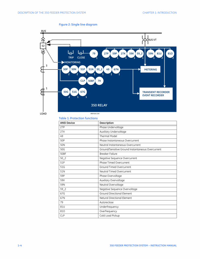
Figure 2: Single line diagram
Table 1: Protection functions
898742A1.CDR
350 RELAY
TRIP
BUS
LOAD
3
1
52
CLOSE
50G/
51G
50P 50N
79
50G 51G
2 2
2 1
METERING
TRANSIENT RECORDER
EVENT RECORDER
51N51P 50_2
1 1 1
49
1
1
27P 59P 27X 59X 59_2 59N 81U 81O
CLP 50BF 79
1 1 1 1 1 1 2 2
MONITORING
BUS VT
67N
67G
1
1
ANSI Device Description
27P Phase Undervoltage
27X Auxiliary Undervoltage
49 Thermal Model
50P Phase Instantaneous Overcurrent
50N Neutral Instantaneous Overcurrent
50G Ground/Sensitive Ground Instantaneous Overcurrent
50BF Breaker Failure
50_2 Negative Sequence Overcurrent
51P Phase Timed Overcurrent
51G Ground Timed Overcurrent
51N Neutral Timed Overcurrent
59P Phase Overvoltage
59X Auxiliary Overvoltage
59N Neutral Overvoltage
59_2 Negative Sequence Overvoltage
67G Ground Directional Element
67N Netural Directional Element
79 Autoreclose
81U Underfrequency
81O Overfrequency
CLP Cold Load Pickup
CHAPTER 1: INTRODUCTION DESCRIPTION OF THE 350 FEEDER PROTECTION SYSTEM
350 FEEDER PROTECTION SYSTEM – INSTRUCTION MANUAL 1–5
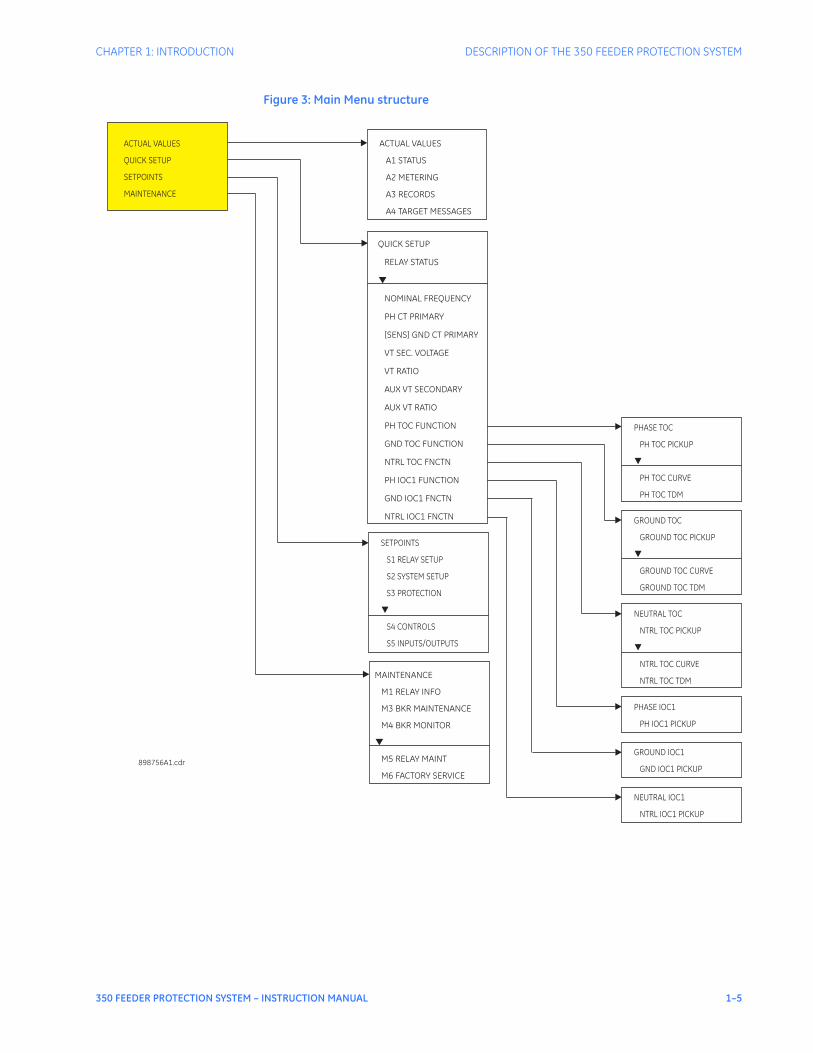
Figure 3: Main Menu structure
ACTUAL VALUES
QUICK SETUP
SETPOINTS
MAINTENANCE
ACTUAL VALUES
A1 STATUS
A2 METERING
A3 RECORDS
A4 TARGET MESSAGES
QUICK SETUP
RELAY STATUS
NOMINAL FREQUENCY
PH CT PRIMARY
[SENS] GND CT
VT SEC. VOLTAGE
VT RATIO
AUX VT SECONDARY
AUX VT RATIO
PH TOC FUNCTION
GND TOC FUNCTION
NTRL TOC FNCTN
PH IOC1 FUNCTION
GND IOC1 FNCTN
NTRL IOC1 FNCTN
PRIMARY
▼
SETPOINTS
S1 RELAY SETUP
S2 SYSTEM SETUP
S3 PROTECTION
S4 CONTROLS
S5 INPUTS/OUTPUTS
▼
MAINTENANCE
M1 RELAY INFO
M3 BKR MAINTENANCE
M5 RELAY MAINT
M6 FACTORY SERVICE
M4 BKR MONITOR
▼
898756A1.cdr
PHASE TOC
PH TOC PICKUP
PH TOC CURVE
PH TOC TDM
▼
GROUND TOC
GROUND TOC PICKUP
GROUND TOC CURVE
GROUND TOC TDM
▼
NEUTRAL TOC
NTRL TOC PICKUP
NTRL TOC CURVE
NTRL TOC TDM
▼
PHASE IOC1
PH IOC1 PICKUP
GROUND IOC1
GND IOC1 PICKUP
NEUTRAL IOC1
NTRL IOC1 PICKUP
1–6 350 FEEDER PROTECTION SYSTEM – INSTRUCTION MANUAL
350 ORDER CODES CHAPTER 1: INTRODUCTION
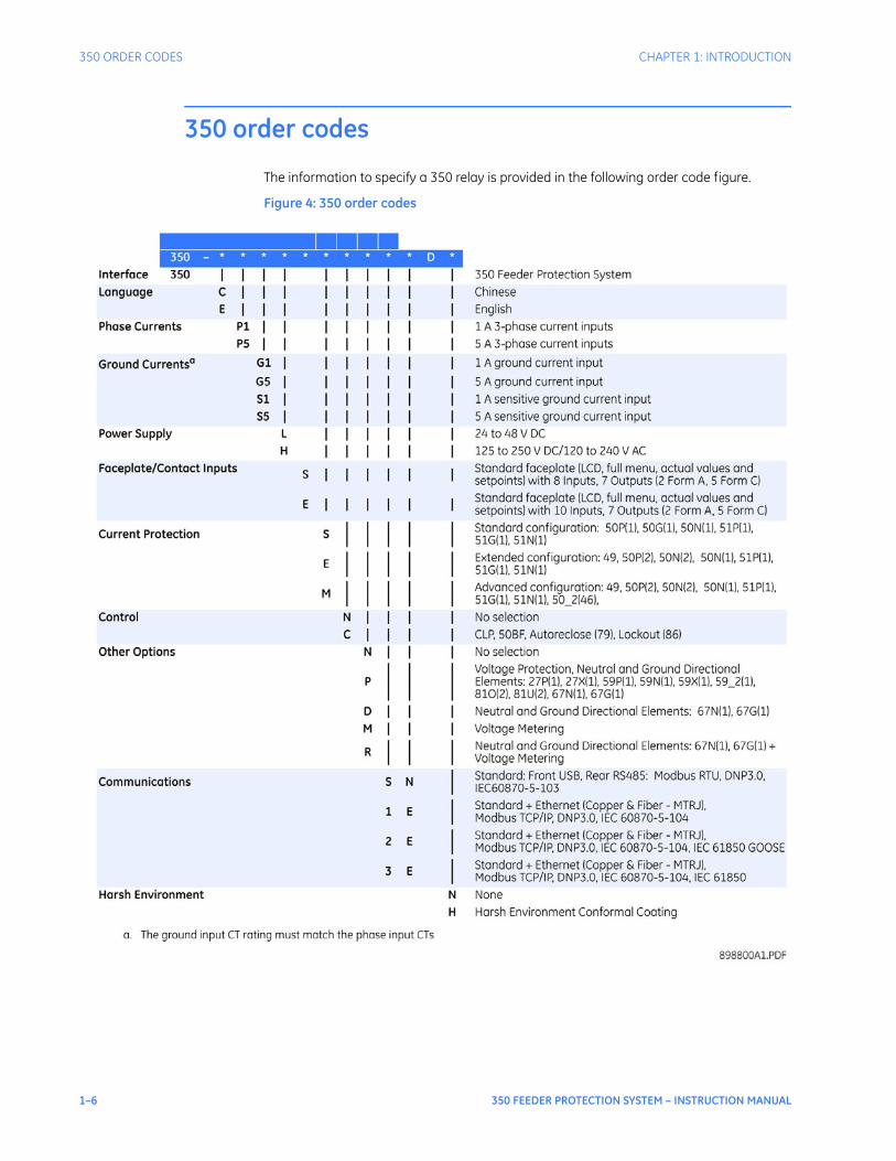
350 order codes
The information to specify a 350 relay is provided in the following order code figure.
Figure 4: 350 order codes
CHAPTER 1: INTRODUCTION SPECIFICATIONS
350 FEEDER PROTECTION SYSTEM – INSTRUCTION MANUAL 1–7
Specifications
NOTE
NOTE: Specifications are subject to change without notice.
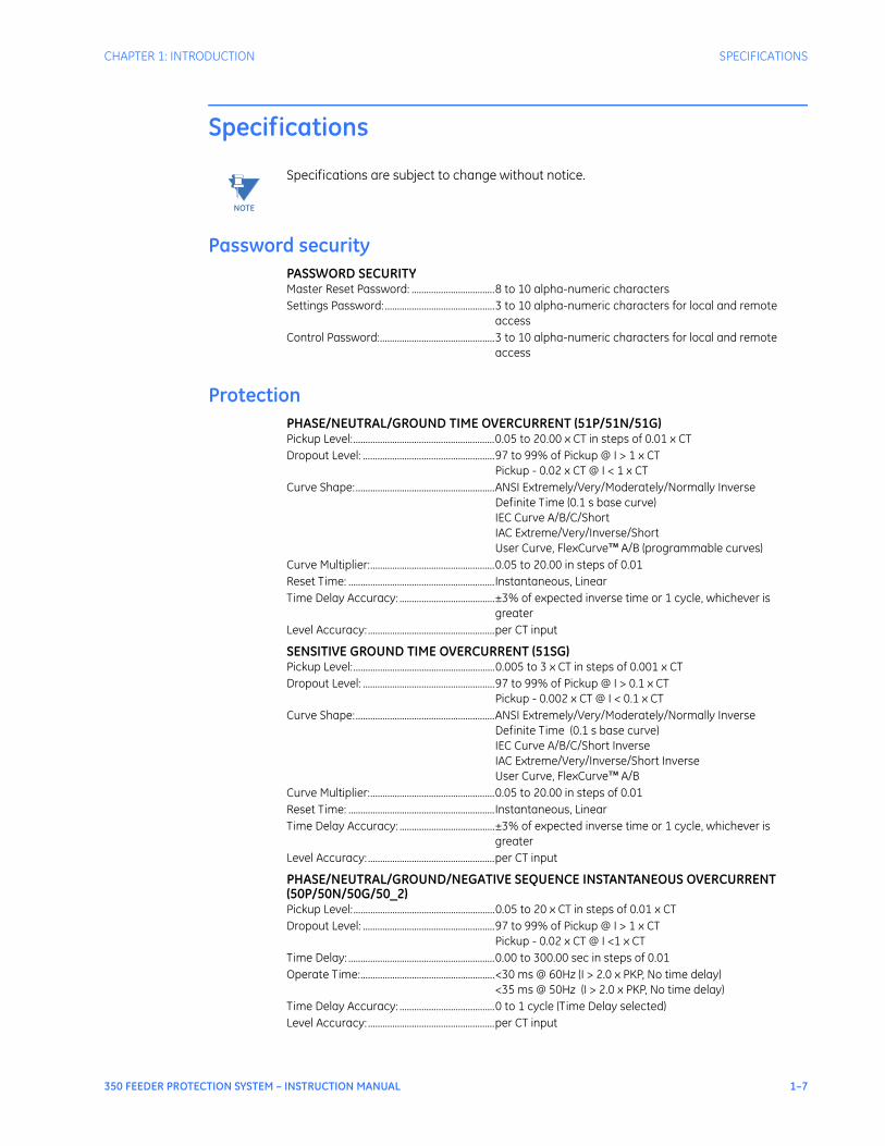
Password securityPASSWORD SECURITYMaster Reset Password: ..................................8 to 10 alpha-numeric charactersSettings Password: .............................................3 to 10 alpha-numeric characters for local and remote
accessControl Password:...............................................3 to 10 alpha-numeric characters for local and remote
access
ProtectionPHASE/NEUTRAL/GROUND TIME OVERCURRENT (51P/51N/51G)Pickup Level:..........................................................0.05 to 20.00 x CT in steps of 0.01 x CTDropout Level: ......................................................97 to 99% of Pickup @ I > 1 x CT
Pickup - 0.02 x CT @ I < 1 x CTCurve Shape:.........................................................ANSI Extremely/Very/Moderately/Normally Inverse
Definite Time (0.1 s base curve)IEC Curve A/B/C/ShortIAC Extreme/Very/Inverse/ShortUser Curve, FlexCurve™ A/B (programmable curves)
Curve Multiplier:...................................................0.05 to 20.00 in steps of 0.01Reset Time: ............................................................Instantaneous, LinearTime Delay Accuracy: .......................................±3% of expected inverse time or 1 cycle, whichever is
greaterLevel Accuracy: ....................................................per CT input
SENSITIVE GROUND TIME OVERCURRENT (51SG)Pickup Level:..........................................................0.005 to 3 x CT in steps of 0.001 x CTDropout Level: ......................................................97 to 99% of Pickup @ I > 0.1 x CT
Pickup - 0.002 x CT @ I < 0.1 x CTCurve Shape:.........................................................ANSI Extremely/Very/Moderately/Normally Inverse
Definite Time (0.1 s base curve)IEC Curve A/B/C/Short InverseIAC Extreme/Very/Inverse/Short InverseUser Curve, FlexCurve™ A/B
Curve Multiplier:...................................................0.05 to 20.00 in steps of 0.01Reset Time: ............................................................Instantaneous, LinearTime Delay Accuracy: .......................................±3% of expected inverse time or 1 cycle, whichever is
greaterLevel Accuracy: ....................................................per CT input
PHASE/NEUTRAL/GROUND/NEGATIVE SEQUENCE INSTANTANEOUS OVERCURRENT (50P/50N/50G/50_2)Pickup Level:..........................................................0.05 to 20 x CT in steps of 0.01 x CTDropout Level: ......................................................97 to 99% of Pickup @ I > 1 x CT
Pickup - 0.02 x CT @ I <1 x CTTime Delay: ............................................................0.00 to 300.00 sec in steps of 0.01Operate Time:.......................................................<30 ms @ 60Hz (I > 2.0 x PKP, No time delay)
<35 ms @ 50Hz (I > 2.0 x PKP, No time delay)Time Delay Accuracy: .......................................0 to 1 cycle (Time Delay selected)Level Accuracy: ....................................................per CT input
1–8 350 FEEDER PROTECTION SYSTEM – INSTRUCTION MANUAL
SPECIFICATIONS CHAPTER 1: INTRODUCTION
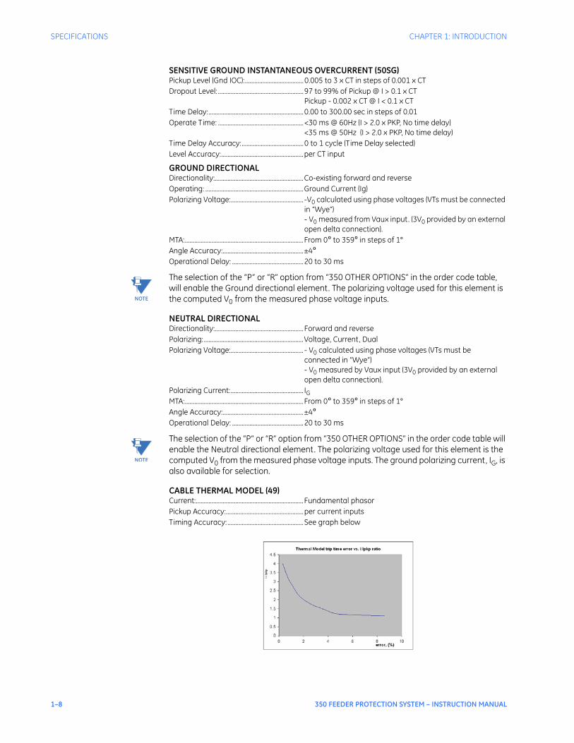
SENSITIVE GROUND INSTANTANEOUS OVERCURRENT (50SG)Pickup Level (Gnd IOC):.....................................0.005 to 3 x CT in steps of 0.001 x CTDropout Level: ......................................................97 to 99% of Pickup @ I > 0.1 x CT
Pickup - 0.002 x CT @ I < 0.1 x CTTime Delay:............................................................0.00 to 300.00 sec in steps of 0.01Operate Time: ......................................................<30 ms @ 60Hz (I > 2.0 x PKP, No time delay)
<35 ms @ 50Hz (I > 2.0 x PKP, No time delay)Time Delay Accuracy:.......................................0 to 1 cycle (Time Delay selected)Level Accuracy:....................................................per CT input
GROUND DIRECTIONALDirectionality:........................................................Co-existing forward and reverseOperating: ..............................................................Ground Current (Ig)Polarizing Voltage:.............................................. -V0 calculated using phase voltages (VTs must be connected
in “Wye”)- V0 measured from Vaux input. (3V0 provided by an external open delta connection).
MTA:........................................................................... From 0º to 359º in steps of 1°Angle Accuracy:...................................................±4ºOperational Delay: .............................................20 to 30 ms
NOTE
NOTE: The selection of the “P” or “R” option from “350 OTHER OPTIONS” in the order code table, will enable the Ground directional element. The polarizing voltage used for this element is the computed V0 from the measured phase voltage inputs.
NEUTRAL DIRECTIONALDirectionality:........................................................ Forward and reversePolarizing:...............................................................Voltage, Current, DualPolarizing Voltage:.............................................. - V0 calculated using phase voltages (VTs must be
connected in “Wye”)- V0 measured by Vaux input (3V0 provided by an external open delta connection).
Polarizing Current:.............................................. IGMTA:........................................................................... From 0º to 359º in steps of 1°Angle Accuracy:...................................................±4ºOperational Delay: .............................................20 to 30 ms
NOTE
NOTE: The selection of the “P” or “R” option from “350 OTHER OPTIONS” in the order code table will enable the Neutral directional element. The polarizing voltage used for this element is the computed V0 from the measured phase voltage inputs. The ground polarizing current, IG, is also available for selection.
CABLE THERMAL MODEL (49)Current:.................................................................... Fundamental phasorPickup Accuracy:.................................................per current inputsTiming Accuracy: ................................................ See graph below
CHAPTER 1: INTRODUCTION SPECIFICATIONS
350 FEEDER PROTECTION SYSTEM – INSTRUCTION MANUAL 1–9
The graph shows the trip time error with respect to the ratio of cable load and thermal model pickup setting. With a smaller I/Ipkp ratio, the time error tends to be higher, as accumulated through the logarithmic formula, the measurement error, and the time of measurement. For higher I/Ipkp ratios, the time to trip is substantially more accurate. Each point on the graph represents a trip time error, with the I/Ipkp ratio kept constant during the test.
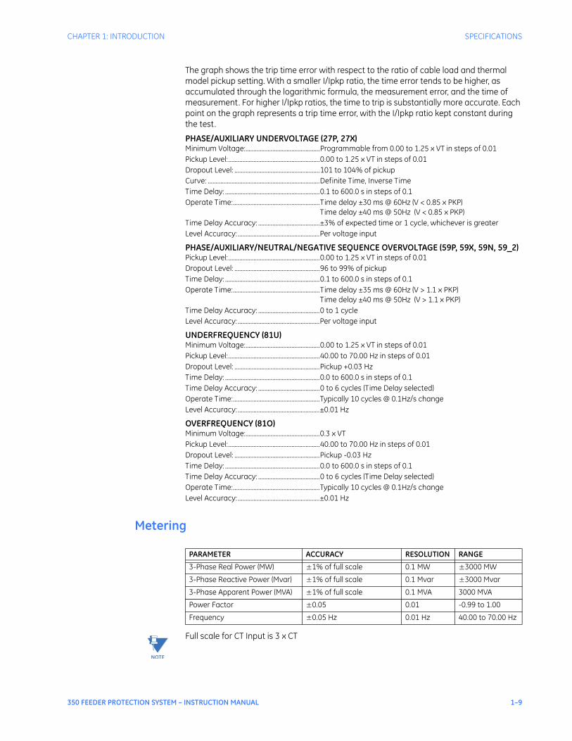
PHASE/AUXILIARY UNDERVOLTAGE (27P, 27X)Minimum Voltage:...............................................Programmable from 0.00 to 1.25 x VT in steps of 0.01Pickup Level:..........................................................0.00 to 1.25 x VT in steps of 0.01Dropout Level: ......................................................101 to 104% of pickupCurve: .......................................................................Definite Time, Inverse TimeTime Delay: ............................................................0.1 to 600.0 s in steps of 0.1Operate Time:.......................................................Time delay ±30 ms @ 60Hz (V < 0.85 x PKP)
Time delay ±40 ms @ 50Hz (V < 0.85 x PKP)Time Delay Accuracy: .......................................±3% of expected time or 1 cycle, whichever is greaterLevel Accuracy: ....................................................Per voltage input
PHASE/AUXILIARY/NEUTRAL/NEGATIVE SEQUENCE OVERVOLTAGE (59P, 59X, 59N, 59_2)Pickup Level:..........................................................0.00 to 1.25 x VT in steps of 0.01Dropout Level: ......................................................96 to 99% of pickupTime Delay: ............................................................0.1 to 600.0 s in steps of 0.1Operate Time:.......................................................Time delay ±35 ms @ 60Hz (V > 1.1 x PKP)
Time delay ±40 ms @ 50Hz (V > 1.1 x PKP)Time Delay Accuracy: .......................................0 to 1 cycleLevel Accuracy: ....................................................Per voltage input
UNDERFREQUENCY (81U)Minimum Voltage:...............................................0.00 to 1.25 x VT in steps of 0.01Pickup Level:..........................................................40.00 to 70.00 Hz in steps of 0.01Dropout Level: ......................................................Pickup +0.03 HzTime Delay: ............................................................0.0 to 600.0 s in steps of 0.1Time Delay Accuracy: .......................................0 to 6 cycles (Time Delay selected)Operate Time:.......................................................Typically 10 cycles @ 0.1Hz/s changeLevel Accuracy: ....................................................±0.01 Hz
OVERFREQUENCY (81O)Minimum Voltage:...............................................0.3 x VTPickup Level:..........................................................40.00 to 70.00 Hz in steps of 0.01Dropout Level: ......................................................Pickup -0.03 HzTime Delay: ............................................................0.0 to 600.0 s in steps of 0.1Time Delay Accuracy: .......................................0 to 6 cycles (Time Delay selected)Operate Time:.......................................................Typically 10 cycles @ 0.1Hz/s changeLevel Accuracy: ....................................................±0.01 Hz
Metering
NOTE
NOTE: Full scale for CT Input is 3 x CT
PARAMETER ACCURACY RESOLUTION RANGE
3-Phase Real Power (MW) ±1% of full scale 0.1 MW ±3000 MW
3-Phase Reactive Power (Mvar) ±1% of full scale 0.1 Mvar ±3000 Mvar
3-Phase Apparent Power (MVA) ±1% of full scale 0.1 MVA 3000 MVA
Power Factor ±0.05 0.01 -0.99 to 1.00
Frequency ±0.05 Hz 0.01 Hz 40.00 to 70.00 Hz
1–10 350 FEEDER PROTECTION SYSTEM – INSTRUCTION MANUAL
SPECIFICATIONS CHAPTER 1: INTRODUCTION
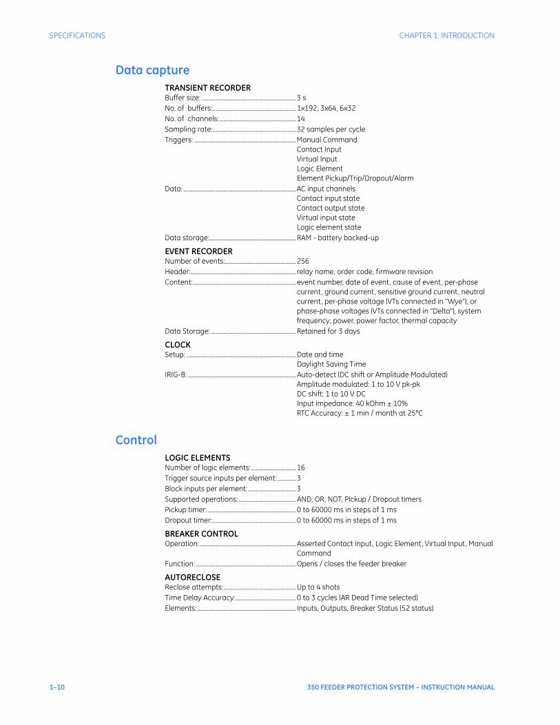
Data captureTRANSIENT RECORDERBuffer size: .............................................................3 s No. of buffers:......................................................1x192, 3x64, 6x32No. of channels:..................................................14 Sampling rate:......................................................32 samples per cycleTriggers: ..................................................................Manual Command
Contact InputVirtual InputLogic ElementElement Pickup/Trip/Dropout/Alarm
Data: .........................................................................AC input channelsContact input stateContact output stateVirtual input stateLogic element state
Data storage:........................................................RAM - battery backed-up
EVENT RECORDERNumber of events:..............................................256 Header:.................................................................... relay name, order code, firmware revision Content:................................................................... event number, date of event, cause of event, per-phase
current, ground current, sensitive ground current, neutral current, per-phase voltage (VTs connected in “Wye”), or phase-phase voltages (VTs connected in “Delta”), system frequency, power, power factor, thermal capacity
Data Storage: .......................................................Retained for 3 days
CLOCKSetup: .......................................................................Date and time
Daylight Saving TimeIRIG-B: ......................................................................Auto-detect (DC shift or Amplitude Modulated)
Amplitude modulated: 1 to 10 V pk-pk DC shift: 1 to 10 V DCInput impedance: 40 kOhm ± 10%RTC Accuracy: ± 1 min / month at 25°C
ControlLOGIC ELEMENTSNumber of logic elements: .............................16Trigger source inputs per element: ............3Block inputs per element: ...............................3Supported operations: .....................................AND, OR, NOT, Pickup / Dropout timersPickup timer: .........................................................0 to 60000 ms in steps of 1 msDropout timer:......................................................0 to 60000 ms in steps of 1 ms
BREAKER CONTROLOperation: ..............................................................Asserted Contact Input, Logic Element, Virtual Input, Manual
CommandFunction: .................................................................Opens / closes the feeder breaker
AUTORECLOSEReclose attempts:...............................................Up to 4 shotsTime Delay Accuracy:.......................................0 to 3 cycles (AR Dead Time selected)Elements: ................................................................ Inputs, Outputs, Breaker Status (52 status)
CHAPTER 1: INTRODUCTION SPECIFICATIONS
350 FEEDER PROTECTION SYSTEM – INSTRUCTION MANUAL 1–11
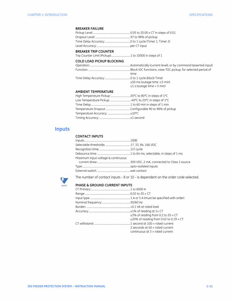
BREAKER FAILUREPickup Level:..........................................................0.05 to 20.00 x CT in steps of 0.01Dropout Level: ......................................................97 to 98% of pickupTime Delay Accuracy: .......................................0 to 1 cycle (Timer 1, Timer 2)Level Accuracy: ....................................................per CT input
BREAKER TRIP COUNTERTrip Counter Limit (Pickup):.............................1 to 10000 in steps of 1
COLD LOAD PICKUP BLOCKINGOperation:...............................................................Automatically (current level), or by command (asserted input)Function: .................................................................Block IOC functions, raise TOC pickup, for selected period of
timeTime Delay Accuracy: .......................................0 to 1 cycle (block Time)
±50 ms (outage time ≤5 min)±1 s (outage time > 5 min)
AMBIENT TEMPERATUREHigh Temperature Pickup: ..............................20°C to 80°C in steps of 1°CLow Temperature Pickup: ...............................-40°C to 20°C in steps of 1°CTime Delay: ............................................................1 to 60 min in steps of 1 minTemperature Dropout:......................................Configurable 90 to 98% of pickupTemperature Accuracy: ...................................±10°CTiming Accuracy: ................................................±1 second
InputsCONTACT INPUTSInputs:.......................................................................10[8]Selectable thresholds: ......................................17, 33, 84, 166 VDCRecognition time: ................................................1/2 cycleDebounce time: ...................................................1 to 64 ms, selectable, in steps of 1 msMaximum input voltage & continuous
current draw:...................................................300 VDC, 2 mA, connected to Class 2 sourceType:..........................................................................opto-isolated inputsExternal switch: ...................................................wet contact
NOTE
NOTE: The number of contact inputs - 8 or 10 - is dependent on the order code selected.
PHASE & GROUND CURRENT INPUTSCT Primary:.............................................................1 to 6000 ARange: ......................................................................0.02 to 20 × CTInput type: ..............................................................1 A or 5 A (must be specified with order)Nominal frequency: ...........................................50/60 HzBurden: ....................................................................<0.1 VA at rated loadAccuracy: ................................................................±1% of reading at 1× CT
±3% of reading from 0.2 to 20 × CT±20% of reading from 0.02 to 0.19 × CT
CT withstand: ........................................................1 second at 100 × rated current 2 seconds at 40 × rated currentcontinuous at 3 × rated current
1–12 350 FEEDER PROTECTION SYSTEM – INSTRUCTION MANUAL
SPECIFICATIONS CHAPTER 1: INTRODUCTION
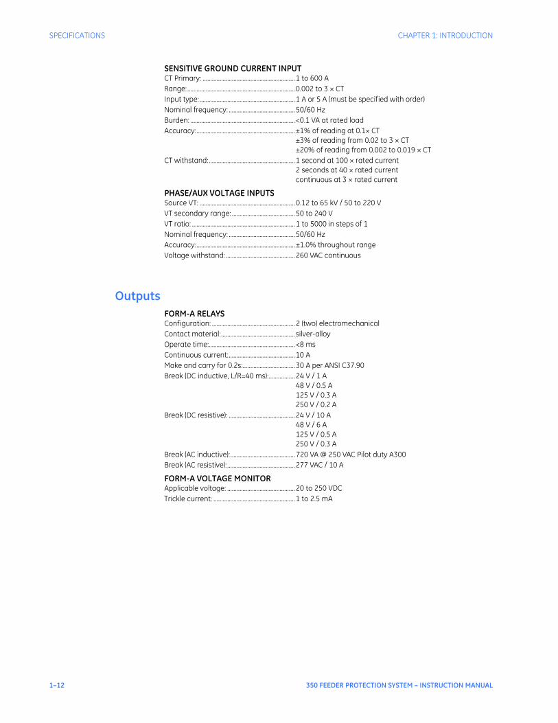
SENSITIVE GROUND CURRENT INPUTCT Primary: ............................................................1 to 600 ARange: ......................................................................0.002 to 3 × CTInput type: ..............................................................1 A or 5 A (must be specified with order)Nominal frequency: ...........................................50/60 HzBurden: ....................................................................<0.1 VA at rated loadAccuracy:................................................................±1% of reading at 0.1× CT
±3% of reading from 0.02 to 3 × CT±20% of reading from 0.002 to 0.019 × CT
CT withstand:........................................................1 second at 100 × rated current 2 seconds at 40 × rated currentcontinuous at 3 × rated current
PHASE/AUX VOLTAGE INPUTSSource VT: ..............................................................0.12 to 65 kV / 50 to 220 VVT secondary range: .........................................50 to 240 VVT ratio: ...................................................................1 to 5000 in steps of 1Nominal frequency: ...........................................50/60 HzAccuracy:................................................................±1.0% throughout rangeVoltage withstand: .............................................260 VAC continuous
OutputsFORM-A RELAYSConfiguration: ......................................................2 (two) electromechanicalContact material:................................................ silver-alloyOperate time:........................................................<8 msContinuous current:...........................................10 AMake and carry for 0.2s:..................................30 A per ANSI C37.90Break (DC inductive, L/R=40 ms):.................24 V / 1 A
48 V / 0.5 A125 V / 0.3 A250 V / 0.2 A
Break (DC resistive): ...........................................24 V / 10 A48 V / 6 A125 V / 0.5 A250 V / 0.3 A
Break (AC inductive):..........................................720 VA @ 250 VAC Pilot duty A300Break (AC resistive): ............................................277 VAC / 10 A
FORM-A VOLTAGE MONITORApplicable voltage: ............................................20 to 250 VDCTrickle current: .....................................................1 to 2.5 mA
CHAPTER 1: INTRODUCTION SPECIFICATIONS
350 FEEDER PROTECTION SYSTEM – INSTRUCTION MANUAL 1–13
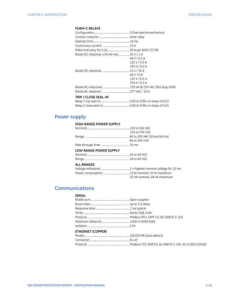
FORM-C RELAYSConfiguration:.......................................................5 (five) electromechanicalContact material: ................................................silver-alloyOperate time:........................................................<8 msContinuous current: ...........................................10 AMake and carry for 0.2s:..................................30 A per ANSI C37.90Break (DC inductive, L/R=40 ms): .................24 V / 1 A
48 V / 0.5 A125 V / 0.3 A250 V / 0.2 A
Break (DC resistive):............................................24 V / 10 A48 V / 6 A125 V / 0.5 A250 V / 0.3 A
Break (AC inductive): ..........................................720 VA @ 250 VAC Pilot duty A300Break (AC resistive): ............................................277 VAC / 10 A
TRIP / CLOSE SEAL-INRelay 1 trip seal-in:.............................................0.00 to 9.99 s in steps of 0.01Relay 2 close seal-in: .........................................0.00 to 9.99 s in steps of 0.01
Power supplyHIGH RANGE POWER SUPPLYNominal: ..................................................................120 to 240 VAC
125 to 250 VDCRange: ......................................................................60 to 300 VAC (50 and 60 Hz)
84 to 300 VDCRide-through time: .............................................35 ms
LOW RANGE POWER SUPPLYNominal: ..................................................................24 to 48 VDCRange: ......................................................................20 to 60 VDC
ALL RANGESVoltage withstand: .............................................2 × highest nominal voltage for 10 msPower consumption: .........................................15 W nominal, 20 W maximum
20 VA nominal, 28 VA maximum
CommunicationsSERIALRS485 port: ............................................................Opto-coupledBaud rates:.............................................................up to 115 kbpsResponse time:.....................................................1 ms typicalParity:........................................................................None, Odd, EvenProtocol: ..................................................................Modbus RTU, DNP 3.0, IEC 60870-5-103Maximum distance: ...........................................1200 m (4000 feet)Isolation:..................................................................2 kV
ETHERNET (COPPER)Modes:......................................................................10/100 MB (auto-detect)Connector:..............................................................RJ-45Protocol: ..................................................................Modbus TCP, DNP3.0, iec 60870-5-104, IEC 61850 GOOSE
1–14 350 FEEDER PROTECTION SYSTEM – INSTRUCTION MANUAL
SPECIFICATIONS CHAPTER 1: INTRODUCTION
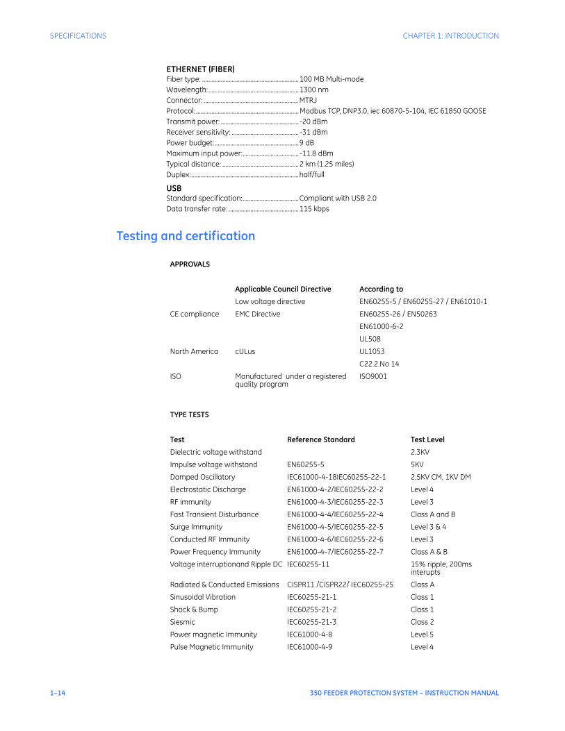
ETHERNET (FIBER)Fiber type: ..............................................................100 MB Multi-modeWavelength:..........................................................1300 nmConnector: .............................................................MTRJProtocol: ..................................................................Modbus TCP, DNP3.0, iec 60870-5-104, IEC 61850 GOOSETransmit power: .................................................. -20 dBmReceiver sensitivity: ........................................... -31 dBmPower budget:......................................................9 dBMaximum input power:.................................... -11.8 dBmTypical distance: .................................................2 km (1.25 miles)Duplex:.....................................................................half/full
USBStandard specification:....................................Compliant with USB 2.0Data transfer rate: .............................................115 kbps
Testing and certification
APPROVALS
Applicable Council Directive According to
Low voltage directive EN60255-5 / EN60255-27 / EN61010-1
CE compliance EMC Directive EN60255-26 / EN50263
EN61000-6-2
UL508
North America cULus UL1053
C22.2.No 14
ISO Manufactured under a registered quality program
ISO9001
TYPE TESTS
Test Reference Standard Test Level
Dielectric voltage withstand 2.3KV
Impulse voltage withstand EN60255-5 5KV
Damped Oscillatory IEC61000-4-18IEC60255-22-1 2.5KV CM, 1KV DM
Electrostatic Discharge EN61000-4-2/IEC60255-22-2 Level 4
RF immunity EN61000-4-3/IEC60255-22-3 Level 3
Fast Transient Disturbance EN61000-4-4/IEC60255-22-4 Class A and B
Surge Immunity EN61000-4-5/IEC60255-22-5 Level 3 & 4
Conducted RF Immunity EN61000-4-6/IEC60255-22-6 Level 3
Power Frequency Immunity EN61000-4-7/IEC60255-22-7 Class A & B
Voltage interruptionand Ripple DC IEC60255-11 15% ripple, 200ms interupts
Radiated & Conducted Emissions CISPR11 /CISPR22/ IEC60255-25 Class A
Sinusoidal Vibration IEC60255-21-1 Class 1
Shock & Bump IEC60255-21-2 Class 1
Siesmic IEC60255-21-3 Class 2
Power magnetic Immunity IEC61000-4-8 Level 5
Pulse Magnetic Immunity IEC61000-4-9 Level 4

CHAPTER 1: INTRODUCTION SPECIFICATIONS
350 FEEDER PROTECTION SYSTEM – INSTRUCTION MANUAL 1–15
PhysicalDIMENSIONSSize: ...........................................................................Refer to Chapter 2Weight:.....................................................................4.1 kg [9.0 lb]
Environmental
Damped Magnetic Immunity IEC61000-4-10 Level 4
Voltage Dip & interruption IEC61000-4-11 0, 40, 70, 80% dips, 250/300 cycle interrupts
Damped Oscillatory IEC61000-4-12 2.5KV CM, 1KV DM
Conducted RF Immunity 0-150khz IEC61000-4-16 Level 4
Voltage Ripple IEC61000-4-17 15% ripple
Ingress Protection IEC60529 IP40 front , IP10 Back
Environmental (Cold) IEC60068-2-1 -40C 16 hrs
Environmental (Dry heat) IEC60068-2-2 85C 16hrs
Relative Humidity Cyclic IEC60068-2-30 6day variant 2
EFT IEEE/ANSI C37.90.1 4KV, 2.5Khz
Damped Oscillatrory IEEE/ANSI C37.90.1 2.5KV,1Mhz
RF Immunity IEEE/ANSIC37.90.2 20V/m 80-1Ghz
ESD IEEE/ANSIC37.90.3 8KV CD/ 15KV AD
UL508 e83849 NKCR
Safety UL C22.2-14 e83849 NKCR7
UL1053 e83849 NKCR
Ambient temperatures:
Storage/Shipping: - 40C to 85C
Operating: -40C to 60C
Humidity: Operating up to 95% (non condensing) @ 55C (As per IEC60068-2-30 Variant 2, 6days)
Altitude: 2000m (max)
Pollution Degree: II
Overvoltage Category: III
Ingress Protection: IP40 Front , IP10 back

1–16 350 FEEDER PROTECTION SYSTEM – INSTRUCTION MANUAL
SPECIFICATIONS CHAPTER 1: INTRODUCTION

350 FEEDER PROTECTION SYSTEM – INSTRUCTION MANUAL 2–1
350 Feeder Protection System
Chapter 2: Installation
Digital EnergyMultilin
Installation
Mechanical installation
This section describes the mechanical installation of the 350 system, including dimensions for mounting and information on module withdrawal and insertion.
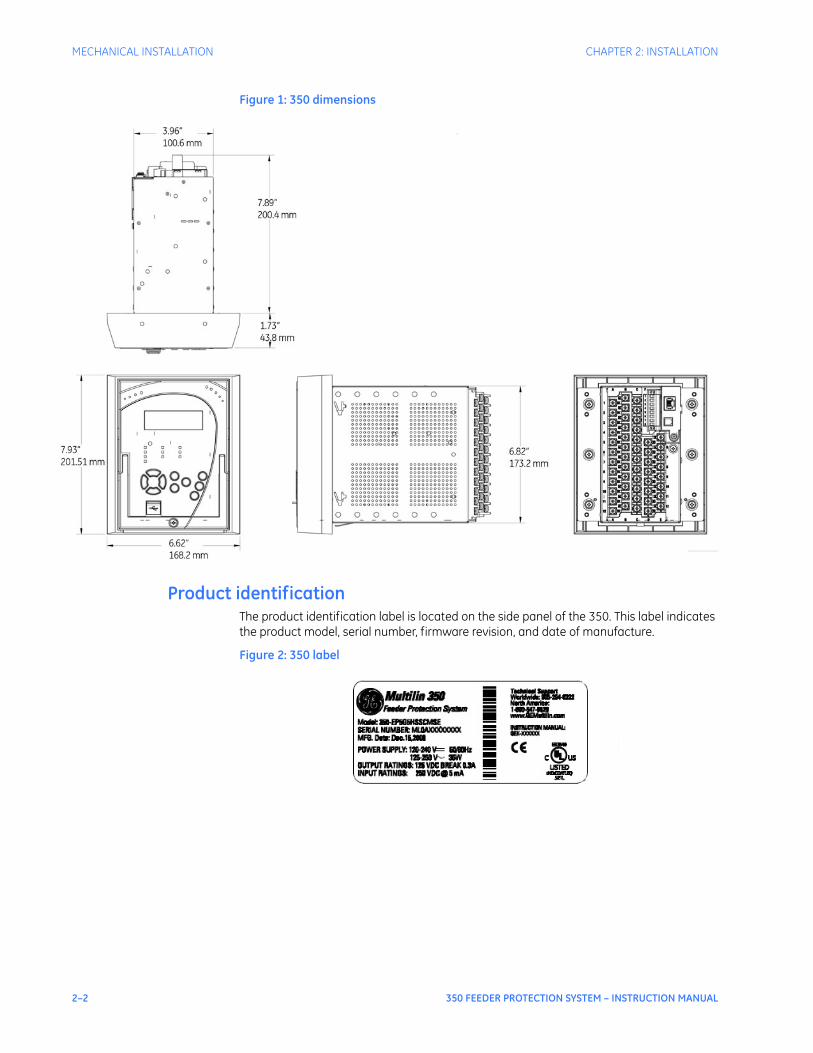
DimensionsThe dimensions of the 350 are shown below. Additional dimensions for mounting and panel cutouts are shown in the following sections.
2–2 350 FEEDER PROTECTION SYSTEM – INSTRUCTION MANUAL
MECHANICAL INSTALLATION CHAPTER 2: INSTALLATION
Figure 1: 350 dimensions
Product identificationThe product identification label is located on the side panel of the 350. This label indicates the product model, serial number, firmware revision, and date of manufacture.
Figure 2: 350 label
CHAPTER 2: INSTALLATION MECHANICAL INSTALLATION
350 FEEDER PROTECTION SYSTEM – INSTRUCTION MANUAL 2–3
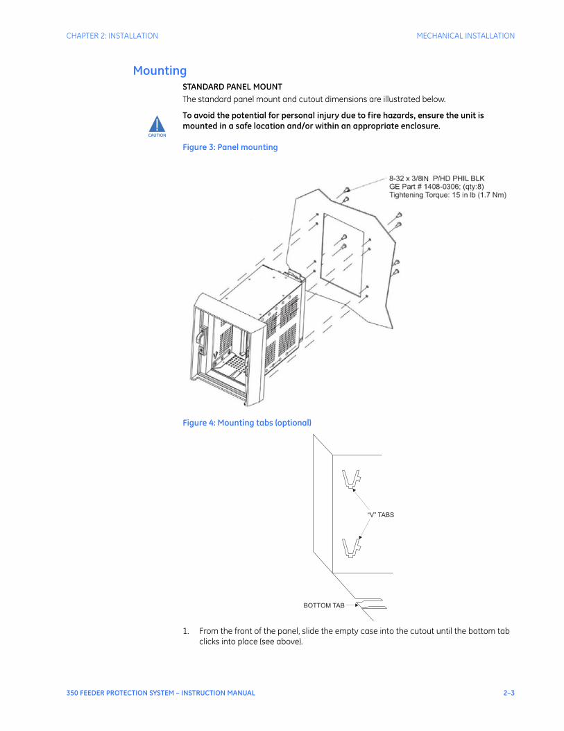
MountingSTANDARD PANEL MOUNTThe standard panel mount and cutout dimensions are illustrated below.
CAUTION
CAUTION: To avoid the potential for personal injury due to fire hazards, ensure the unit is mounted in a safe location and/or within an appropriate enclosure.
Figure 3: Panel mounting
Figure 4: Mounting tabs (optional)
1. From the front of the panel, slide the empty case into the cutout until the bottom tab clicks into place (see above).
BOTTOM TAB
“V” TABS
2–4 350 FEEDER PROTECTION SYSTEM – INSTRUCTION MANUAL
MECHANICAL INSTALLATION CHAPTER 2: INSTALLATION
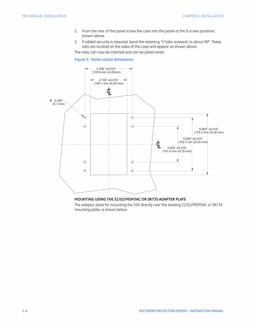
2. From the rear of the panel screw the case into the panel at the 8 screw positions shown above.
3. If added security is required, bend the retaining "V"tabs outward, to about 90°. These tabs are located on the sides of the case and appear as shown above.
The relay can now be inserted and can be panel wired.
Figure 5: Panel cutout dimensions
MOUNTING USING THE S1/S2/MDP/IAC OR SR735 ADAPTER PLATEThe adaptor plate for mounting the 350 directly over the existing S1/S2/MDP/IAC or SR735 mounting plate, is shown below:
5.350” 0.010”
(135.9 mm 0.25mm)
±
±
4.100” 0.010”
(104.1 mm 0.25 mm)
±
±
0.200”
(5.1 mm)
Φ
6.900” 0.010”
(175.3 mm 0.25 mm)
±
±
6.000” 0.010”
(152.4 mm 0.25 mm)
±
±
4.000” 0.010”
(101.6 mm 0.25 mm)
±
±
CL
CL
CHAPTER 2: INSTALLATION MECHANICAL INSTALLATION
350 FEEDER PROTECTION SYSTEM – INSTRUCTION MANUAL 2–5
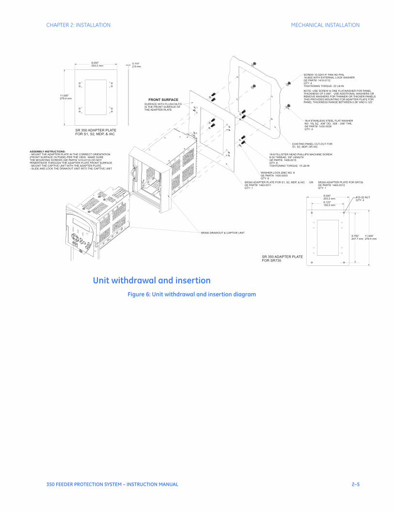
Unit withdrawal and insertionFigure 6: Unit withdrawal and insertion diagram
SR350 ADAPTER PLATE FOR S1, S2, MDP, & IAC
GE PART#: 1463-0011
QTY: 1
ASSEMBLY INSTRUCTIONS:
- MOUNT THE ADAPTER PLATE IN THE CORRECT ORIENTATION
(FRONT SURFACE OUTSIDE) PER THE VIEW. MAKE SURE
THE MOUNTING SCREWS (GE PART# 1410-0112) DO NOT
PENERTRATE THROUGH THE ADAPTER PLATE FRONT SURFACE.
- MOUNT THE CAPTIVE UNIT WITH THE ADAPTER PLATE.
- SLIDE AND LOCK THE DRAWOUT UNIT INTO THE CAPTIVE UNIT.
SR350 DRAWOUT & CAPTIVE UNIT
WASHER LOCK ZINC NO. 8
GE PART#: 1430-0003
QTY: 8
18-8 FILLISTER HEAD PHILLIPS MACHINE SCREW
8-32 THREAD, 3/8” LENGTH
GE PART#: 1408-0015
QTY: 8
TIGHTENING TORQUE: 15 LB-IN
EXISTING PANEL CUT-OUT FOR
S1, S2, MDP, OR IAC
18-8 STAINLESS STEEL FLAT WASHER
NO. 10L SZ, .438” OD, .028 - .036” THK,
GE PART#: 1430-0039
QTY: 4
NOTE: USE SCREW & ONE FLATWASHER FOR PANEL
THICKNESS OF 0.090”. USE ADDITIONAL WASHERS OR
REMOVE WASHERS FOR THINNER OR THICKER PANELS.
THIS PROVIDES MOUNTING FOR ADAPTER PLATE FOR
PANEL THICKNESS RANGE BETWEEN 0.06” AND 0.125”.
SCREW 10-32X1/4” PAN HD PHIL
18-8SS WITH EXTERNAL LOCK WASHER
GE PART#: 1410-0112
QTY: 4
TIGHTENING TORQUE: 22 LB-IN
SURFACE WITH FLUSH NUTS
IS THE FRONT SURFACE OF
THE ADAPTER PLATE
FRONT SURFACE
SR 350 ADAPTER PLATE
FOR S1, S2, MDP, & IAC
11.000”
279.4 mm
8.000”
203.2 mm0.114”
2.9 mm
SR 350 ADAPTER PLATE
FOR SR735
11.000”
279.4 mm
8.000”
203.2 mm
6.123”
155.5 mm
9.750”
247.7 mm
#10-32 NUT
QTY: 4
OR SR350 ADAPTER PLATE FOR SR735
GE PART#: 1463-0012
QTY: 1
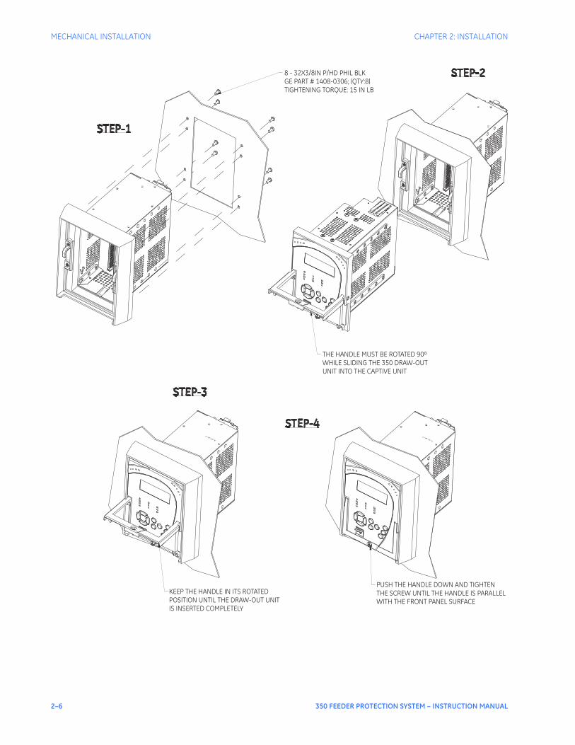
2–6 350 FEEDER PROTECTION SYSTEM – INSTRUCTION MANUAL
MECHANICAL INSTALLATION CHAPTER 2: INSTALLATION
KEEP THE HANDLE IN ITS ROTATEDPOSITION UNTIL THE DRAW-OUT UNITIS INSERTED COMPLETELY
PUSH THE HANDLE DOWN AND TIGHTENTHE SCREW UNTIL THE HANDLE IS PARALLELWITH THE FRONT PANEL SURFACE
THE HANDLE MUST BE ROTATED 90WHILE SLIDING THE 350 DRAW-OUTUNIT INTO THE CAPTIVE UNIT
⁰
8 - 32X3/8IN P/HD PHIL BLKGE PART # 1408-0306; (QTY:8)TIGHTENING TORQUE: 15 IN LB
CHAPTER 2: INSTALLATION ELECTRICAL INSTALLATION
350 FEEDER PROTECTION SYSTEM – INSTRUCTION MANUAL 2–7
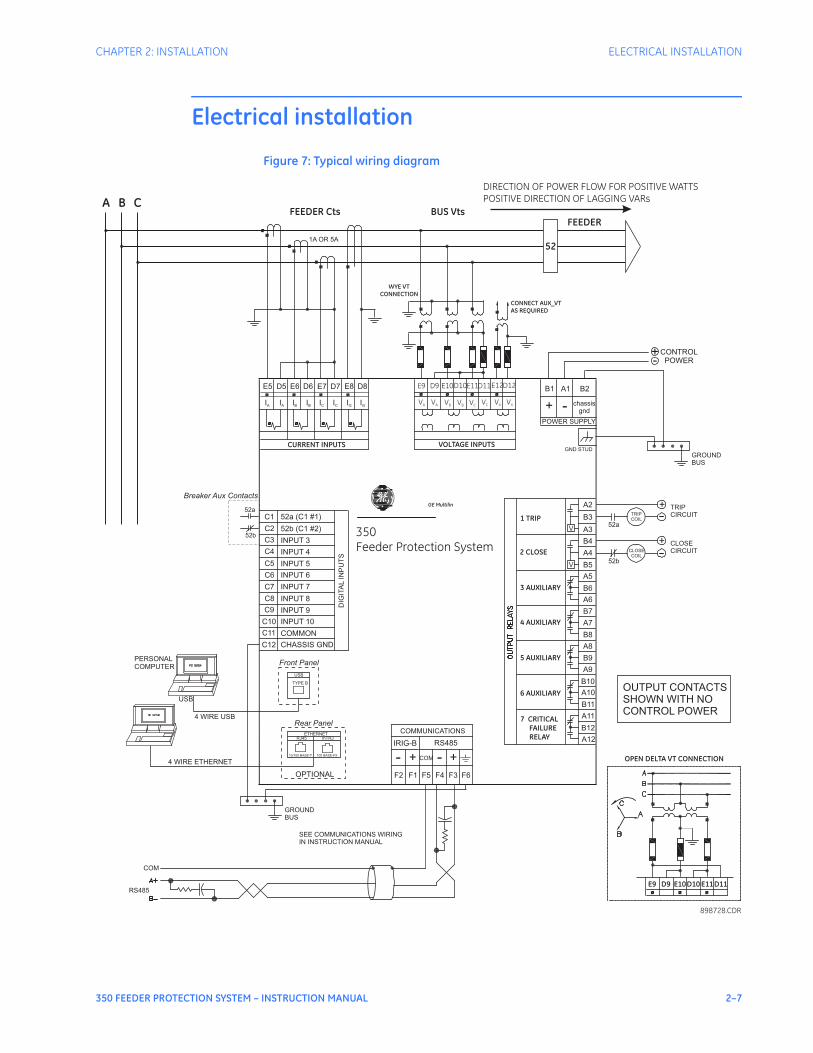
Electrical installation
Figure 7: Typical wiring diagram
898728.CDR
POWER SUPPLY
B1 A1 B2
+ - chassis
gnd
C1
C2
C3
C4
C5
C6
C7
C8
C9
C10
DIG
ITA
LIN
PU
TS
52a (C1 #1)
52b (C1 #2)
INPUT 3
INPUT 4
INPUT 5
INPUT 6
INPUT 7
INPUT 8
INPUT 9
INPUT 10
ETHERNET
RJ45 mTRJ
10/100 BASE-T 100 BASE-FX
USB
TYPE B
A5
A6
A7
A2
A3
A4
A8
A9
A10
A11
A12
B3
B4
B5
B6
B7
B8
B9
B10
B11
B12
V
V
4 WIRE USB
4 WIRE ETHERNET
USB
+
+
F5 F4 F3
-- ++
RS485IRIG-B
F1F2
COMMUNICATIONS
+-
CONTROL
POWER
A B C
FEEDER
BUS Vts
52
E5 D5 E6 D6 E7 D7 E8 D8
IA
IA
IB
IB
IC
IC
IG
IG
FEEDER Cts
CONNECT AUX_VT
AS REQUIRED
VOLTAGE INPUTS
WYE VT
CONNECTION
E9 D9 E10D10E11D11E12D12
VA VA VB VB VCVC VX VX
7 CRITICAL
FAILURE
RELAY
3 AUXILIARY
4 AUXILIARY
5 AUXILIARY
6 AUXILIARY
2 CLOSE
1 TRIP
OPEN DELTA VT CONNECTION
E9 D9 E10D10 E11 D11
OPTIONAL
DIRECTION OF POWER FLOW FOR POSITIVE WATTSPOSITIVE DIRECTION OF LAGGING VARs
Front Panel
Rear Panel
350Feeder Protection System
52a
52b
Breaker Aux Contacts
C11
C12
COMMON
CHASSIS GND
CURRENT INPUTS
PERSONAL
COMPUTER
OUTPUT CONTACTS
SHOWN WITH NO
CONTROL POWER
TRIP
CIRCUIT
CLOSE
CIRCUIT
TRIP
COIL
CLOSE
COIL
52b
52a
GROUND
BUS
SEE COMMUNICATIONS WIRING
IN INSTRUCTION MANUAL
1A OR 5A
COM
GE Multilin
COM
RS485
GROUND
BUS
F6
GND STUD
2–8 350 FEEDER PROTECTION SYSTEM – INSTRUCTION MANUAL
ELECTRICAL INSTALLATION CHAPTER 2: INSTALLATION
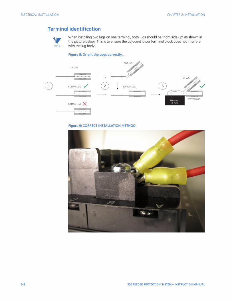
Terminal identification
NOTE
NOTE: When installing two lugs on one terminal, both lugs should be "right side up" as shown in the picture below. This is to ensure the adjacent lower terminal block does not interfere with the lug body.
Figure 8: Orient the Lugs correctly...
Figure 9: CORRECT INSTALLATION METHOD
TOP LUG
BOTTOM LUG
INSULATION
INSULATION
INSULATION
INSULATION
TOP LUG
BOTTOM LUG
INSULATION
INSULATION
INSULATIO
N
INSULATIO
N
TOP LUG
BOTTOM LUG
INSULATION
INSULATION
INSULATIO
N
INSULATIO
N
TERMINALBLOCK
SCREW*
1 2 3
BOTTOM LUG
INSULATION
INSULATION
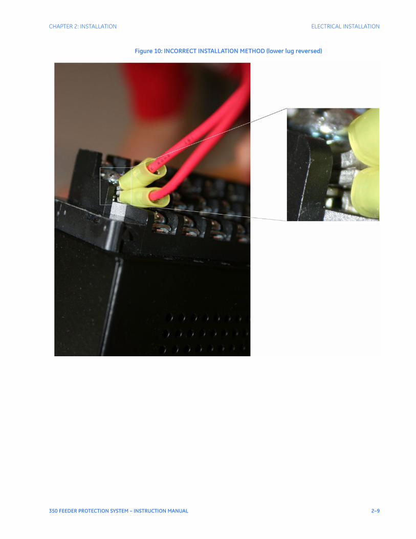
CHAPTER 2: INSTALLATION ELECTRICAL INSTALLATION
350 FEEDER PROTECTION SYSTEM – INSTRUCTION MANUAL 2–9
Figure 10: INCORRECT INSTALLATION METHOD (lower lug reversed)
2–10 350 FEEDER PROTECTION SYSTEM – INSTRUCTION MANUAL
ELECTRICAL INSTALLATION CHAPTER 2: INSTALLATION
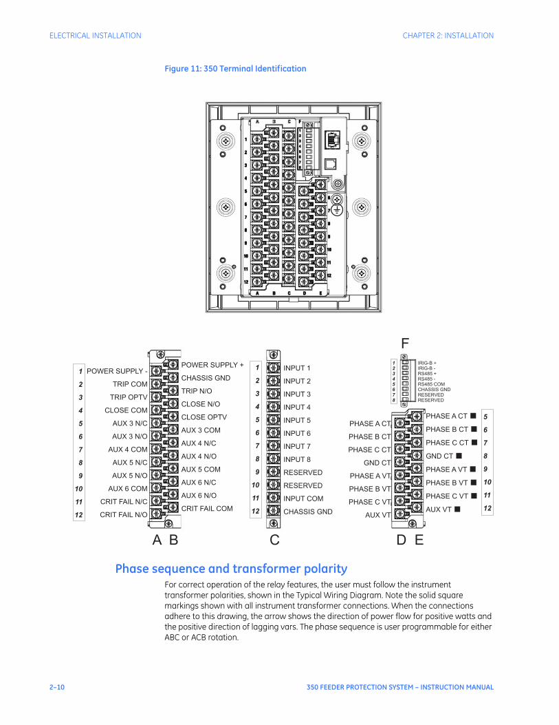
Figure 11: 350 Terminal Identification
Phase sequence and transformer polarityFor correct operation of the relay features, the user must follow the instrument transformer polarities, shown in the Typical Wiring Diagram. Note the solid square markings shown with all instrument transformer connections. When the connections adhere to this drawing, the arrow shows the direction of power flow for positive watts and the positive direction of lagging vars. The phase sequence is user programmable for either ABC or ACB rotation.
INPUT 1
INPUT 2
INPUT 3
INPUT 4
INPUT 5
INPUT 6
INPUT 7
INPUT 8
RESERVED
RESERVED
INPUT COM
CHASSIS GND
PHASE A CT
PHASE B CT
PHASE C CT
GND CT
PHASE A VT
PHASE B VT
PHASE C VT
AUX VT
PHASE A CT
PHASE B CT
PHASE C CT
GND CT
PHASE A VT
PHASE B VT
PHASE C VT
AUX VT
■
■
■
■
■
■
■
■
IRIG-B +
IRIG-B -
RS485 +
RS485 -
RS485 COM
CHASSIS GND
RESERVED
RESERVED
POWER SUPPLY +
CHASSIS GND
TRIP N/O
CLOSE N/O
CLOSE OPTV
AUX 3 COM
AUX 4 N/C
AUX 4 N/O
AUX 5 COM
AUX 6 N/C
AUX 6 N/O
CRIT FAIL COM
POWER SUPPLY -
TRIP COM
TRIP OPTV
CLOSE COM
AUX 3 N/C
AUX 3 N/O
AUX 4 COM
AUX 5 N/C
AUX 5 N/O
AUX 6 COM
CRIT FAIL N/C
CRIT FAIL N/O
1
2
3
4
5
6
7
8
9
10
11
12
1
2
3
4
5
6
7
8
9
10
11
12
5
6
7
8
9
10
11
12
A B C D E
F
1
2
3
4
5
6
7
8
CHAPTER 2: INSTALLATION ELECTRICAL INSTALLATION
350 FEEDER PROTECTION SYSTEM – INSTRUCTION MANUAL 2–11
Current inputsThe 350 relay has four (4) channels for AC current inputs, each with an isolating transformer. There are no internal ground connections on the current inputs. Current transformers with 1 to 6000 A primaries may be used.
CAUTION
CAUTION: Verify that the relay’s nominal input current of 1 A or 5 A matches the secondary rating of the connected CTs. Unmatched CTs may result in equipment damage or inadequate protection.
CAUTION
CAUTION: IMPORTANT: The phase and ground current inputs will correctly measure up to 20 times the current input’s nominal rating. Time overcurrent curves become horizontal lines for currents above the 20 × CT rating. This becomes apparent if the pickup level is set above the nominal CT rating.
CAUTION
CAUTION: Before working on CTs, they MUST be short circuited.
Ground and sensitive ground CT inputsOne dedicated ground input is referred to throughout this manual as the Ground Current or Sensitive Ground Current input. Before making ground connections, consider that the relay automatically calculates the neutral (residual) current from the sum of the three phase current phasors. The following figures show three possible ground connections (or three possible sensitive ground connections).The ground input (Terminals D8 and E8) is used in conjunction with a Zero Sequence CT as source, or in the neutral of wye-connected source CTs. The ground current input can be used to polarize the neutral directional element. When using the residual connection set the GROUND CT PRIMARY setpoint to a value equal to the PHASE CT PRIMARY setpoint.In cases where the relay is equipped with sensitive ground CT (terminals D8 and E8) the sensitive ground current input is intended for use either with a CT in a source neutral of a high-impedance grounded system, or on ungrounded systems. On ungrounded systems it is connected residually with the phase current inputs. In this case, the SENSTV GND CT PRIMARY setpoint should be programmed to a value equal to the PHASE CT PRIMARY setpoint. The sensitive ground current input can be connected to a Zero Sequence CT for increased sensitivity and accuracy when physically possible in the system.
NOTE
NOTE: The Sensitive Ground input must only be used on systems where the maximum ground current does not exceed 100 times the rated current for 1 second.
2–12 350 FEEDER PROTECTION SYSTEM – INSTRUCTION MANUAL
ELECTRICAL INSTALLATION CHAPTER 2: INSTALLATION
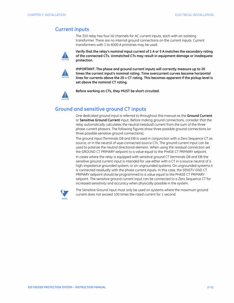
Figure 12: Ground/Sensitive Ground wiring
Zero sequence CT installationThe various CT connections and the exact placement of a Zero Sequence CT, for ground fault current detection, are shown in the figure below. Twisted pair cabling on the Zero Sequence CT is recommended.
Figure 13: Zero sequence core balance (CT) installation
SOURCE
898730.CDR898730.CDR
A
B
C
USED FOR POLARIZINGUSED FOR POLARIZING
GROUND CURRENT INPUTGROUND CURRENT INPUT
SR350
PHASE CURRENTPHASE CURRENT
INPUTS
A B C
GROUND CURRENT INPUTGROUND CURRENT INPUT
WITH ZERO SEQUENCE CTWITH ZERO SEQUENCE CT
GROUND CURRENT INPUTGROUND CURRENT INPUT
WITH RESIDUAL CONNECTIONWITH RESIDUAL CONNECTION
E8 D8
G
GROUND
I N NIG
E5
D5 D6
E6
D7
E7
GIN
GROUND
D8 E8
GROUND
D8E8
Ground connection to neutralmust be on the source side
UNSHIELDED CABLE
LOAD
A B C N G
Groundoutside CT
Source
LOAD
SHIELDED CABLE
898733.CDR
A B C
Source
To ground;must be onload side
Stress coneshields
CHAPTER 2: INSTALLATION ELECTRICAL INSTALLATION
350 FEEDER PROTECTION SYSTEM – INSTRUCTION MANUAL 2–13
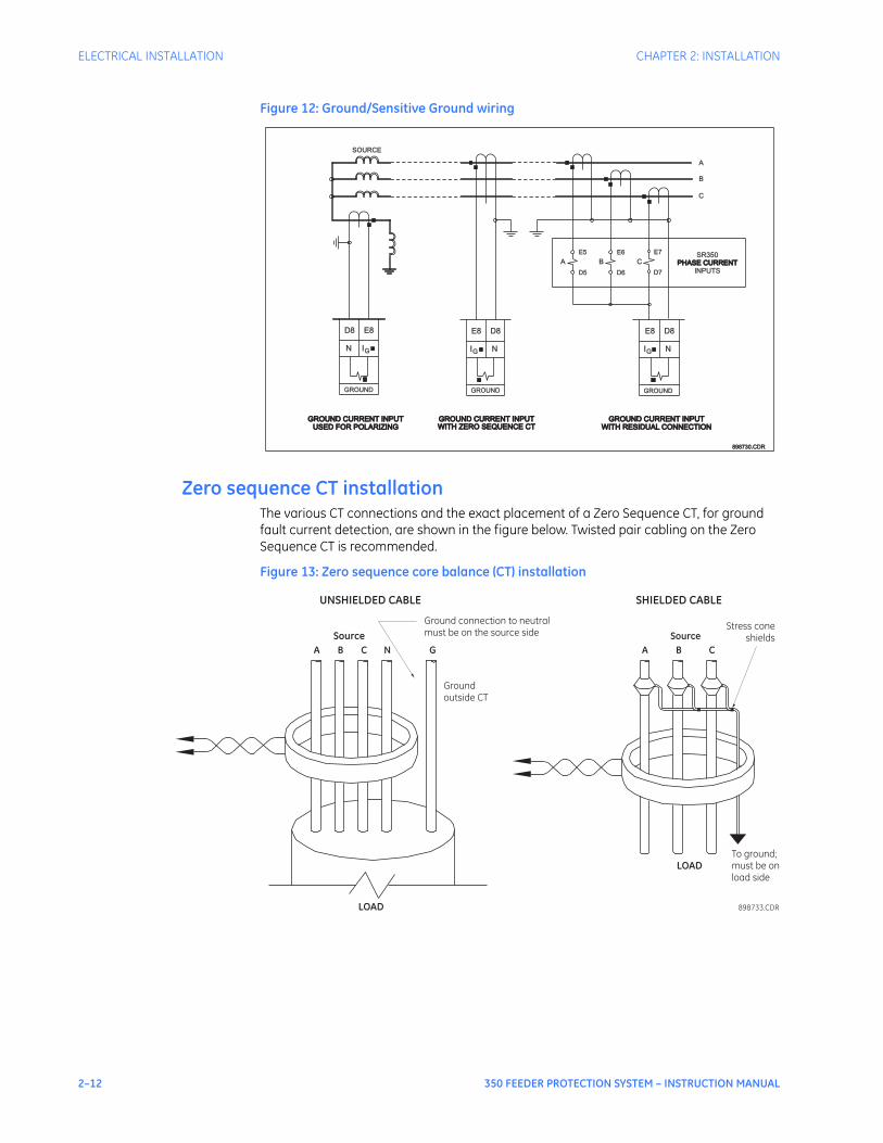
Voltage inputsThe 350 relay has four channels for AC voltage inputs, each with an isolating transformer. Voltage transformers up to a maximum 5000:1 ratio may be used. The nominal secondary voltage must be in the 50 to 240 V range.The three phase inputs are designated as the “bus voltage”. The Bus VT connections most commonly used, wye and delta (or open delta), are shown in the typical wiring diagram.
NOTE
NOTE: If Delta VTs are used, the zero sequence voltage (V0) and neutral/sensitive ground polarizing voltage (–V0) will be zero. Also, with the Delta VT connection, the phase-neutral voltage cannot be measured and will not be displayed.
NOTE
NOTE: The 350 relay can be applied to both metering and protection feeders with up to 65 kV phase-to-phase voltage. Please ensure that the selected VT ratio and VT secondary do not result in a primary voltage exceeding 65 kV.
The single phase input is designated as the “Aux VT Input”. The Aux VT input channel can be connected for either phase-neutral voltage Van, Vbn, Vcn, or for phase-phase voltage Vab, Vbc, Vca as shown below.
Figure 14: Auxiliary VT connections
Control power
CAUTION
CAUTION: Control power supplied to the relay must match the installed power supply range. If the applied voltage does not match, damage to the unit may occur. All grounds MUST be connected for safe, normal operation regardless of control power supply type.
The label found on the relay specifies its order code or model number. The installed power supply’s operating range will be one of the following:
LO: 24 to 48 V DC (Range: 20 to 60 V DC)HI: 125 to 250 V DC/120 to 240 V AC (Range: 84 to 250 V DC/66 to 265 V AC)
CAUTION
CAUTION: The relay should be connected directly to the ground bus, using the shortest practical path. A tinned copper, braided, shielding and bonding cable should be used. As a minimum, 96 strands of number 34 AWG should be used. Belden catalog number 8660 is suitable.
CAUTION
CAUTION: Isolate power prior to servicing.
FFEEDERTO BUS VTsTO BUS VTs
A
C
B
E12
AUX
D12
VV1 2 V
E12
1 V2
AUX
D12
2V1V
AUX
E12 D12
2V1V
AUX
E12 D12
V1 V2
AUX
E12 D12
Van Vbn Vcn Vab Vbc
898734.CDR
V1 V2
AUX
E12 D12
Vca
2–14 350 FEEDER PROTECTION SYSTEM – INSTRUCTION MANUAL
ELECTRICAL INSTALLATION CHAPTER 2: INSTALLATION
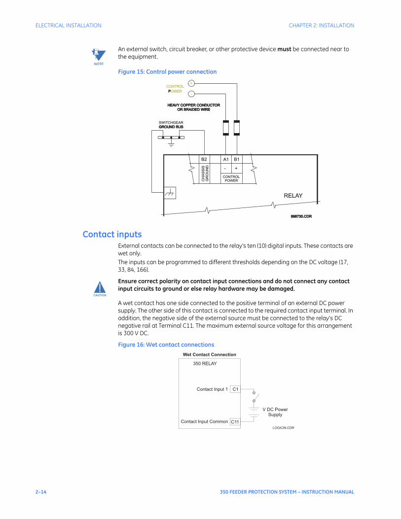
NOTE
NOTE: An external switch, circuit breaker, or other protective device must be connected near to the equipment.
Figure 15: Control power connection
Contact inputsExternal contacts can be connected to the relay’s ten (10) digital inputs. These contacts are wet only.The inputs can be programmed to different thresholds depending on the DC voltage (17, 33, 84, 166).
CAUTION
CAUTION: Ensure correct polarity on contact input connections and do not connect any contact input circuits to ground or else relay hardware may be damaged.
A wet contact has one side connected to the positive terminal of an external DC power supply. The other side of this contact is connected to the required contact input terminal. In addition, the negative side of the external source must be connected to the relay’s DC negative rail at Terminal C11. The maximum external source voltage for this arrangement is 300 V DC.
Figure 16: Wet contact connections
PPOWER
OR BRAIDED WIREOR BRAIDED WIRE
HEAVY COPPER CONDUCTORHEAVY COPPER CONDUCTOR
GROUND BUSGROUND BUS
SWITCHGEAR
-
+
GR
OU
ND
B2 A1 B1
+-
CH
AS
SIS
RELAY
CONTROL
898735.CDR898735.CDR
CONTROL
POWER
Wet Contact Connection
350 RELAY
C1Contact Input 1
Contact Input Common C11
V DC Power
Supply
LOGICIN.CDR
CHAPTER 2: INSTALLATION ELECTRICAL INSTALLATION
350 FEEDER PROTECTION SYSTEM – INSTRUCTION MANUAL 2–15
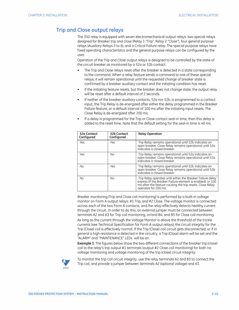
Trip and Close output relaysThe 350 relay is equipped with seven electromechanical output relays: two special relays designed for Breaker trip and close (Relay 1 “Trip”, Relay 2 “Close”), four general purpose relays (Auxiliary Relays 3 to 6), and a Critical Failure relay. The special purpose relays have fixed operating characteristics and the general purpose relays can be configured by the user. Operation of the Trip and Close output relays is designed to be controlled by the state of the circuit breaker as monitored by a 52a or 52b contact. • The Trip and Close relays reset after the breaker is detected in a state corresponding
to the command. When a relay feature sends a command to one of these special relays, it will remain operational until the requested change of breaker state is confirmed by a breaker auxiliary contact and the initiating condition has reset.
• If the initiating feature resets, but the breaker does not change state, the output relay will be reset after a default interval of 2 seconds.
• If neither of the breaker auxiliary contacts, 52a nor 52b, is programmed to a contact input, the Trip Relay is de-energized after either the delay programmed in the Breaker Failure feature, or a default interval of 100 ms after the initiating input resets. The Close Relay is de-energized after 200 ms.
• If a delay is programmed for the Trip or Close contact seal-in time, then this delay is added to the reset time. Note that the default setting for the seal-in time is 40 ms.
Breaker monitoring (Trip and Close coil monitoring) is performed by a built-in voltage monitor on Form A output relays: #1 Trip, and #2 Close. The voltage monitor is connected across each of the two Form A contacts, and the relay effectively detects healthy current through the circuit. In order to do this, an external jumper must be connected between terminals A2 and A3 for Trip coil monitoring, or/and B4, and B5 for Close coil monitoring. As long as the current through the Voltage Monitor is above the threshold of the trickle currents (see Technical Specification for Form A output relays), the circuit integrity for the Trip (Close) coil is effectively normal. If the Trip (Close) coil circuit gets disconnected, or if in general a high resistance is detected in the circuitry, a Trip (Close) alarm will be set and the “ALARM” and “MAINTENANCE” LEDs will be on. Example 1: The figures below show the two different connections of the breaker trip (close) coil to the relay’s trip output #1 terminals (output #2 Close coil monitoring) for both no voltage monitoring and voltage monitoring of the trip (close) circuit integrity.
NOTE
NOTE: To monitor the trip coil circuit integrity, use the relay terminals A2 and B3 to connect the Trip coil, and provide a jumper between terminals A2 (optional voltage) and A3.
52a Contact Configured
52b Contact Configured
Relay Operation
Yes Yes Trip Relay remains operational until 52b indicates an open breaker. Close Relay remains operational until 52a indicates a closed breaker.
Yes No Trip Relay remains operational until 52a indicates an open breaker. Close Relay remains operational until 52a indicates a closed breaker.
No Yes Trip Relay remains operational until 52b indicates an open breaker. Close Relay remains operational until 52b indicates a closed breaker.
No No Trip Relay operates until either the Breaker Failure delay expires (if the Breaker Failure element is enabled), or 100 ms after the feature causing the trip resets. Close Relay operates for 200 ms.
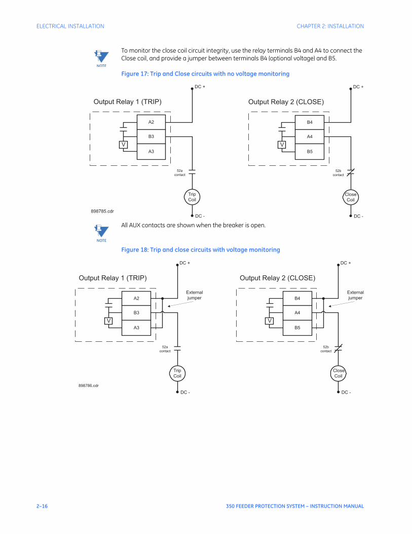
2–16 350 FEEDER PROTECTION SYSTEM – INSTRUCTION MANUAL
ELECTRICAL INSTALLATION CHAPTER 2: INSTALLATION
NOTE
NOTE: To monitor the close coil circuit integrity, use the relay terminals B4 and A4 to connect the Close coil, and provide a jumper between terminals B4 (optional voltage) and B5.
Figure 17: Trip and Close circuits with no voltage monitoring
NOTE
NOTE: All AUX contacts are shown when the breaker is open.
Figure 18: Trip and close circuits with voltage monitoring
V
A2
B3
A3
Trip
Coil
DC +
DC -
Output Relay 1 (TRIP)
52a
contact
V
B4
A4
B5
Close
Coil
DC +
DC -
Output Relay 2 (CLOSE)
52b
contact
898785.cdr
V
A2
B3
A3
Trip
Coil
DC +
DC -
Output Relay 1 (TRIP)
52a
contact
External
jumper
898786.cdr
V
B4
A4
B5
Close
Coil
DC +
DC -
Output Relay 2 (CLOSE)
52b
contact
External
jumper
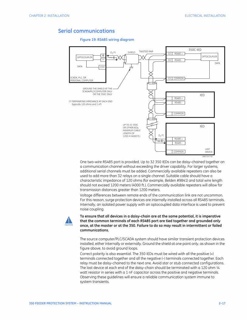
CHAPTER 2: INSTALLATION ELECTRICAL INSTALLATION
350 FEEDER PROTECTION SYSTEM – INSTRUCTION MANUAL 2–17
Serial communicationsFigure 19: RS485 wiring diagram
One two-wire RS485 port is provided. Up to 32 350 IEDs can be daisy-chained together on a communication channel without exceeding the driver capability. For larger systems, additional serial channels must be added. Commercially available repeaters can also be used to add more than 32 relays on a single channel. Suitable cable should have a characteristic impedance of 120 ohms (for example, Belden #9841) and total wire length should not exceed 1200 meters (4000 ft.). Commercially available repeaters will allow for transmission distances greater than 1200 meters.Voltage differences between remote ends of the communication link are not uncommon. For this reason, surge protection devices are internally installed across all RS485 terminals. Internally, an isolated power supply with an optocoupled data interface is used to prevent noise coupling.
CAUTION
CAUTION: To ensure that all devices in a daisy-chain are at the same potential, it is imperative that the common terminals of each RS485 port are tied together and grounded only once, at the master or at the 350. Failure to do so may result in intermittent or failed communications.
The source computer/PLC/SCADA system should have similar transient protection devices installed, either internally or externally. Ground the shield at one point only, as shown in the figure above, to avoid ground loops.Correct polarity is also essential. The 350 IEDs must be wired with all the positive (+) terminals connected together and all the negative (–) terminals connected together. Each relay must be daisy-chained to the next one. Avoid star or stub connected configurations. The last device at each end of the daisy-chain should be terminated with a 120 ohm ¼ watt resistor in series with a 1 nF capacitor across the positive and negative terminals. Observing these guidelines will ensure a reliable communication system immune to system transients.
SCADA, PLC, ORPERSONAL COMPUTER
COM
OPTOCOUPLER
DATA
350C IEDSHIELD
898738.CDR
UP TO 32 350COR OTHER IEDs,MAXIMUM CABLELENGTH OF1200 m (4000 ft.)
LASTDEVICE
(*) TERMINATING IMPEDANCE AT EACH END(typically 120 ohms and 1 nF)
TWISTED PAIR
ZT (*)
RS485 +
RS485 -
COMMON
RS485 +
RS485 -
COMMON
IED
RS485 +
IED
RS485 -
COMMON
GROUND THE SHIELD AT THESCADA/PLC/COMPUTER ONLY
OR THE 350C ONLY
DATA
OPTOCOUPLER
E2
D2
E3
ZT (*)
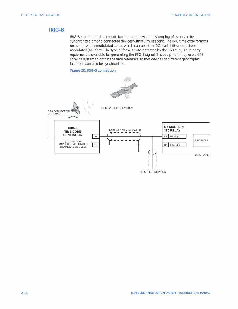
2–18 350 FEEDER PROTECTION SYSTEM – INSTRUCTION MANUAL
ELECTRICAL INSTALLATION CHAPTER 2: INSTALLATION
IRIG-BIRIG-B is a standard time code format that allows time stamping of events to be synchronized among connected devices within 1 millisecond. The IRIG time code formats are serial, width-modulated codes which can be either DC level shift or amplitude modulated (AM) form. The type of form is auto-detected by the 350 relay. Third party equipment is available for generating the IRIG-B signal; this equipment may use a GPS satellite system to obtain the time reference so that devices at different geographic locations can also be synchronized.
Figure 20: IRIG-B connection
GE MULTILIN
350 RELAY
IRIG-B(-)
RECEIVER
TO OTHER DEVICES
RG58/59 COAXIAL CABLE
GPS SATELLITE SYSTEM
GPS CONNECTION
OPTIONAL
IRIG-B(+)E1
D1
+
–
898741.CDR
IRIG-B
TIME CODE
GENERATOR
(DC SHIFT OR
AMPLITUDE MODULATED
SIGNAL CAN BE USED)

350 FEEDER PROTECTION SYSTEM – INSTRUCTION MANUAL 3–1
350 Feeder Protection System
Chapter 3: Interfaces
Digital EnergyMultilin
Interfaces
There are two methods of interfacing with the 350 Feeder Protection System.• Interfacing via the relay keypad and display.• Interfacing via the EnerVista SR3 Setup software.This section provides an overview of the interfacing methods available with the 350 using the relay control panels and EnerVista SR3 Setup software. For additional details on interface parameters (for example, settings, actual values, etc.), refer to the individual chapters.
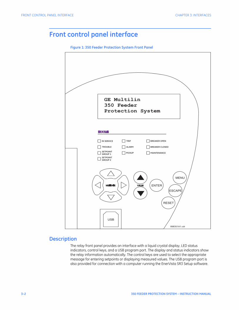
3–2 350 FEEDER PROTECTION SYSTEM – INSTRUCTION MANUAL
FRONT CONTROL PANEL INTERFACE CHAPTER 3: INTERFACES
Front control panel interface
Figure 1: 350 Feeder Protection System Front Panel
DescriptionThe relay front panel provides an interface with a liquid crystal display, LED status indicators, control keys, and a USB program port. The display and status indicators show the relay information automatically. The control keys are used to select the appropriate message for entering setpoints or displaying measured values. The USB program port is also provided for connection with a computer running the EnerVista SR3 Setup software.
▽
△
◁ ▷▲
▼
ENTER
MENU
ESCAPE
RESET
898351A1.cdr
USB
GE Multilin
350 Feeder
Protection System
IN SERVICE
TROUBLE
SETPOINT
GROUP 1
SETPOINT
GROUP 2
TRIP
ALARM
PICKUP
BREAKER OPEN
BREAKER CLOSED
MAINTENANCE
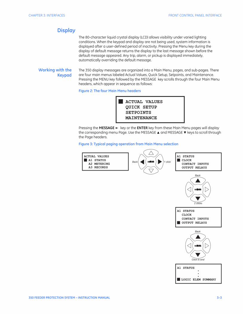
CHAPTER 3: INTERFACES FRONT CONTROL PANEL INTERFACE
350 FEEDER PROTECTION SYSTEM – INSTRUCTION MANUAL 3–3
DisplayThe 80-character liquid crystal display (LCD) allows visibility under varied lighting conditions. When the keypad and display are not being used, system information is displayed after a user-defined period of inactivity. Pressing the Menu key during the display of default message returns the display to the last message shown before the default message appeared. Any trip, alarm, or pickup is displayed immediately, automatically overriding the default message.
Working with theKeypad
The 350 display messages are organized into a Main Menu, pages, and sub-pages. There are four main menus labeled Actual Values, Quick Setup, Setpoints, and Maintenance. Pressing the MENU key followed by the MESSAGE key scrolls through the four Main Menu headers, which appear in sequence as follows:
Figure 2: The four Main Menu headers
Pressing the MESSAGE ► key or the ENTER key from these Main Menu pages will display the corresponding menu Page. Use the MESSAGE ▲ and MESSAGE ▼ keys to scroll through the Page headers.
Figure 3: Typical paging operation from Main Menu selection
█ ACTUAL VALUES
QUICK SETUP
SETPOINTS
MAINTENANCE
█ CLOCK
A1 STATUS
CONTACT INPUTS
OUTPUT RELAYS
█
ACTUAL VALUES
A1 STATUS
A2 METERING
A3 RECORDS
█
CONTACT INPUTS
A1 STATUS
OUTPUT RELAYS
CLOCK
█
A1 STATUS
LOGIC ELEM SUMMARY
.
.
.
2 clicks
▽
△
▶
▶
▼
◁ ▷
▼
▼
◁ ▷
Click to end
▼Back
Back
Back 1 click
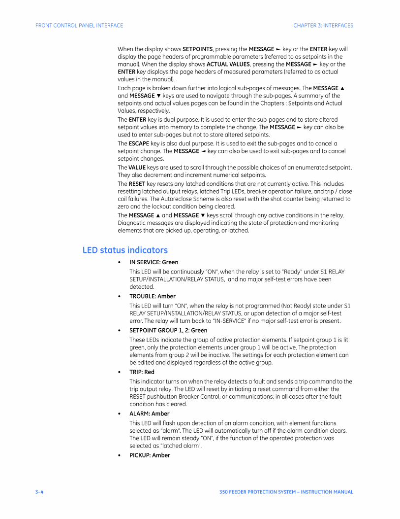
3–4 350 FEEDER PROTECTION SYSTEM – INSTRUCTION MANUAL
FRONT CONTROL PANEL INTERFACE CHAPTER 3: INTERFACES
When the display shows SETPOINTS, pressing the MESSAGE ► key or the ENTER key will display the page headers of programmable parameters (referred to as setpoints in the manual). When the display shows ACTUAL VALUES, pressing the MESSAGE ► key or the ENTER key displays the page headers of measured parameters (referred to as actual values in the manual). Each page is broken down further into logical sub-pages of messages. The MESSAGE ▲ and MESSAGE ▼ keys are used to navigate through the sub-pages. A summary of the setpoints and actual values pages can be found in the Chapters : Setpoints and Actual Values, respectively.The ENTER key is dual purpose. It is used to enter the sub-pages and to store altered setpoint values into memory to complete the change. The MESSAGE ► key can also be used to enter sub-pages but not to store altered setpoints.The ESCAPE key is also dual purpose. It is used to exit the sub-pages and to cancel a setpoint change. The MESSAGE ◄ key can also be used to exit sub-pages and to cancel setpoint changes.The VALUE keys are used to scroll through the possible choices of an enumerated setpoint. They also decrement and increment numerical setpoints. The RESET key resets any latched conditions that are not currently active. This includes resetting latched output relays, latched Trip LEDs, breaker operation failure, and trip / close coil failures. The Autoreclose Scheme is also reset with the shot counter being returned to zero and the lockout condition being cleared.The MESSAGE ▲ and MESSAGE ▼ keys scroll through any active conditions in the relay. Diagnostic messages are displayed indicating the state of protection and monitoring elements that are picked up, operating, or latched.
LED status indicators• IN SERVICE: Green
This LED will be continuously “ON”, when the relay is set to “Ready” under S1 RELAY SETUP/INSTALLATION/RELAY STATUS, and no major self-test errors have been detected.
• TROUBLE: AmberThis LED will turn “ON”, when the relay is not programmed (Not Ready) state under S1 RELAY SETUP/INSTALLATION/RELAY STATUS, or upon detection of a major self-test error. The relay will turn back to “IN-SERVICE” if no major self-test error is present.
• SETPOINT GROUP 1, 2: GreenThese LEDs indicate the group of active protection elements. If setpoint group 1 is lit green, only the protection elements under group 1 will be active. The protection elements from group 2 will be inactive. The settings for each protection element can be edited and displayed regardless of the active group.
• TRIP: RedThis indicator turns on when the relay detects a fault and sends a trip command to the trip output relay. The LED will reset by initiating a reset command from either the RESET pushbutton Breaker Control, or communications; in all cases after the fault condition has cleared.
• ALARM: AmberThis LED will flash upon detection of an alarm condition, with element functions selected as “alarm”. The LED will automatically turn off if the alarm condition clears. The LED will remain steady “ON”, if the function of the operated protection was selected as "latched alarm".
• PICKUP: Amber

CHAPTER 3: INTERFACES FRONT CONTROL PANEL INTERFACE
350 FEEDER PROTECTION SYSTEM – INSTRUCTION MANUAL 3–5
This indicator will light ON upon pickup condition generated by any of the relay features. The indicator will turn off if no pickup condition is detected.
• BREAKER OPEN: Red/Green – programmableWhen the breaker is open, this indicator will be on continuously.
• BREAKER CLOSED: Red/Green – programmableWhen the breaker is closed, this indicator will be on continuously.Breaker status indication is based on the breaker’s 52a and 52b contacts. With both contacts wired to the relay, closed breaker status is determined by closed 52a contact and opened 52b contact. Visa-versa the open breaker status is determined by opened 52a contact and closed 52b contact. If both 52a and 52b contacts are open, due to a breaker being racked out from the switchgear, both the Breaker Open and Breaker Closed LED Indicators will be off.
NOTE
NOTE: It is strongly recommended to detect the breaker status by using both 52a and 52b contacts.
The 350 provides also detecting the breaker status by using only one contact: either 52a or 52b. However, one should be aware that in such cases, it would be impossible to distinguish between a breaker open state and breaker racked out state, unless another contact from the breaker is wired to the relay.To clarify this ambiguity, the BKR CONNECTED function under SETPOINTS/S2 SYSTEM SETUP/S2 BREAKER should be programmed to an additional contact input. When this additional input is closed, a single 52a or 52b contact will show both breaker states. When the breaker is racked out, this additional breaker connected input should be open. In this case, both breaker status indicators will be off.
• MAINTENANCE: AmberThis LED may indicate both breaker or relay maintenance depending on the programmed maintenance elements. The LED will turn on upon operation of a maintenance element.
Relay messages
Target messages Target messages are automatically displayed for any active condition on the relay such as pickups, trips, or alarms.The relay displays the most recent event first, and after 5 seconds will start rolling up the other target messages until the conditions clear and/or the RESET command is initiated. The Target Messages can be reviewed by pressing either the MESSAGE UP or MESSAGE DOWN key. If a RESET command is not performed but any of the other faceplate pushbuttons is pressed, the display will not show the target messages unless the user navigates to ACTUAL VALUES > A4 TARGET MESSAGES, where they can be reviewed. If the target messages have not been cleared before the user presses a pushbutton different from “RESET”, they will reappear on the screen after the time specified under the SETPOINTS > S1 RELAY SETUP > S1 FRONT PANEL > MESSAGE TIMEOUT setting, that will start timing out from the last pressed pushbutton. The following shows the format of a typical Target Message:
Figure 4: Typical target message
A4 TARGET MESSAGES
Cause <function>
State: Operate
Phase:▼
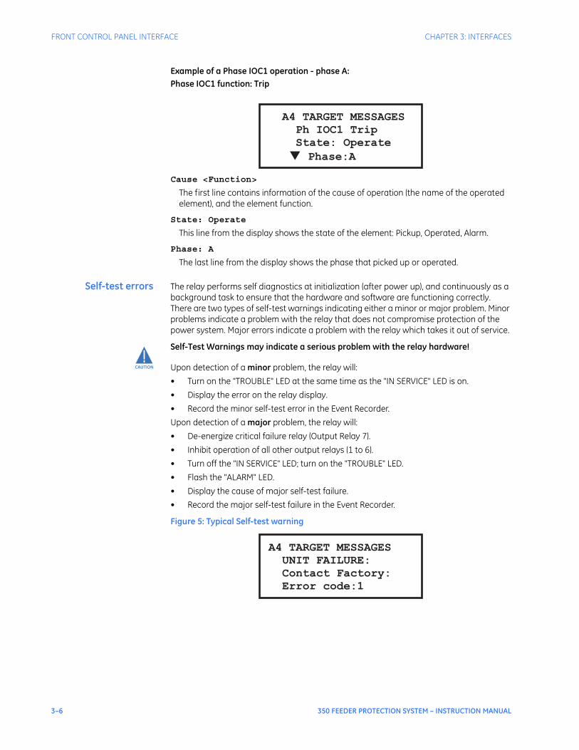
3–6 350 FEEDER PROTECTION SYSTEM – INSTRUCTION MANUAL
FRONT CONTROL PANEL INTERFACE CHAPTER 3: INTERFACES
Example of a Phase IOC1 operation - phase A:Phase IOC1 function: Trip
Cause <Function>
The first line contains information of the cause of operation (the name of the operated element), and the element function.
State: Operate
This line from the display shows the state of the element: Pickup, Operated, Alarm.
Phase: A
The last line from the display shows the phase that picked up or operated.
Self-test errors The relay performs self diagnostics at initialization (after power up), and continuously as a background task to ensure that the hardware and software are functioning correctly. There are two types of self-test warnings indicating either a minor or major problem. Minor problems indicate a problem with the relay that does not compromise protection of the power system. Major errors indicate a problem with the relay which takes it out of service.
CAUTION
CAUTION: Self-Test Warnings may indicate a serious problem with the relay hardware!
Upon detection of a minor problem, the relay will:• Turn on the "TROUBLE" LED at the same time as the "IN SERVICE" LED is on.• Display the error on the relay display.• Record the minor self-test error in the Event Recorder.Upon detection of a major problem, the relay will:• De-energize critical failure relay (Output Relay 7). • Inhibit operation of all other output relays (1 to 6).• Turn off the "IN SERVICE" LED; turn on the "TROUBLE" LED.• Flash the "ALARM" LED.• Display the cause of major self-test failure. • Record the major self-test failure in the Event Recorder.
Figure 5: Typical Self-test warning
A4 TARGET MESSAGES
Ph IOC1 Trip
State: Operate
Phase:A▼
A4 TARGET MESSAGES
UNIT FAILURE:
Contact Factory:
Error code:1
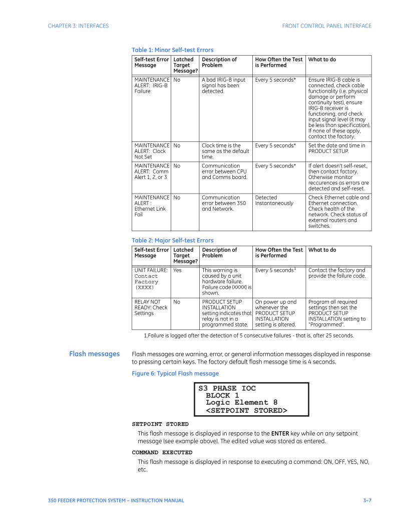
CHAPTER 3: INTERFACES FRONT CONTROL PANEL INTERFACE
350 FEEDER PROTECTION SYSTEM – INSTRUCTION MANUAL 3–7
Table 1: Minor Self-test Errors
Table 2: Major Self-test Errors
Flash messages Flash messages are warning, error, or general information messages displayed in response to pressing certain keys. The factory default flash message time is 4 seconds.
Figure 6: Typical Flash message
SETPOINT STORED
This flash message is displayed in response to the ENTER key while on any setpoint message (see example above). The edited value was stored as entered.
COMMAND EXECUTED
This flash message is displayed in response to executing a command: ON, OFF, YES, NO, etc.
Self-test Error Message
Latched Target Message?
Description of Problem
How Often the Test is Performed
What to do
MAINTENANCE ALERT: IRIG-B Failure
No A bad IRIG-B input signal has been detected.
Every 5 seconds* Ensure IRIG-B cable is connected, check cable functionality (i.e. physical damage or perform continuity test), ensure IRIG-B receiver is functioning, and check input signal level (it may be less than specification). If none of these apply, contact the factory.
MAINTENANCE ALERT: Clock Not Set
No Clock time is the same as the default time.
Every 5 seconds* Set the date and time in PRODUCT SETUP.
MAINTENANCE ALERT: Comm Alert 1, 2, or 3
No Communication error between CPU and Comms board.
Every 5 seconds* If alert doesn’t self-reset, then contact factory. Otherwise monitor reccurences as errors are detected and self-reset.
MAINTENANCEALERT : Ethernet Link Fail
No Communication error between 350 and Network.
Detected Instantaneously
Check Ethernet cable and Ethernet connection. Check health of the network. Check status of external routers and switches.
Self-test Error Message
Latched Target Message?
Description of Problem
How Often the Test is Performed
What to do
UNIT FAILURE: Contact Factory (XXXX)
Yes This warning is caused by a unit hardware failure. Failure code (XXXX) is shown.
Every 5 seconds1
1.Failure is logged after the detection of 5 consecutive failures - that is, after 25 seconds.
Contact the factory and provide the failure code.
RELAY NOT READY: Check Settings
No PRODUCT SETUP INSTALLATION setting indicates that relay is not in a programmed state.
On power up and whenever the PRODUCT SETUP INSTALLATION setting is altered.
Program all required settings then set the PRODUCT SETUP INSTALLATION setting to "Programmed".
BLOCK 1Logic Element 8
S3 PHASE IOC
<SETPOINT STORED>

3–8 350 FEEDER PROTECTION SYSTEM – INSTRUCTION MANUAL
FRONT CONTROL PANEL INTERFACE CHAPTER 3: INTERFACES
INVALID PASSWORD
This flash message appears upon an attempt to enter an incorrect password, as part of password security.
AR IN PROGRESS
This flash message appears when the Autoreclosure is in progress performing the configured sequence.
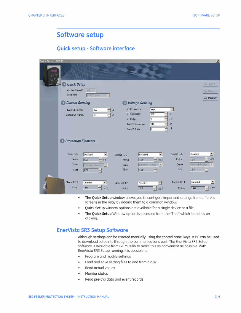
CHAPTER 3: INTERFACES SOFTWARE SETUP
350 FEEDER PROTECTION SYSTEM – INSTRUCTION MANUAL 3–9
Software setup
Quick setup - Software interface
• The Quick Setup window allows you to configure important settings from different screens in the relay by adding them to a common window.
• Quick Setup window options are available for a single device or a file.• The Quick Setup Window option is accessed from the "Tree" which launches on
clicking.
EnerVista SR3 Setup SoftwareAlthough settings can be entered manually using the control panel keys, a PC can be used to download setpoints through the communications port. The EnerVista SR3 Setup software is available from GE Multilin to make this as convenient as possible. With EnerVista SR3 Setup running, it is possible to:• Program and modify settings• Load and save setting files to and from a disk• Read actual values• Monitor status• Read pre-trip data and event records

3–10 350 FEEDER PROTECTION SYSTEM – INSTRUCTION MANUAL
SOFTWARE SETUP CHAPTER 3: INTERFACES
• Get help on any topic• Upgrade the 350 firmwareThe EnerVista SR3 Setup software allows immediate access to all 350 features with easy to use pull down menus in the familiar Windows environment. This section provides the necessary information to install EnerVista SR3 Setup, upgrade the relay firmware, and write and edit setting files.The EnerVista SR3 Setup software can run without a 350 connected to the computer. In this case, settings may be saved to a file for future use. If a 350 is connected to a PC and communications are enabled, the 350 can be programmed from the setting screens. In addition, measured values, status and trip messages can be displayed with the actual value screens.
Hardware andsoftware
requirements
The following requirements must be met for the EnerVista SR3 Setup software.• Microsoft Windows™ 7 / XP is installed and running properly.• At least 100 MB of hard disk space is available.• At least 256 MB of RAM is installed.The EnerVista SR3 Setup software can be installed from either the GE EnerVista CD or the GE Multilin website at http://www.GEmultilin.com.
Installing theEnerVista SR3 Setup
software
After ensuring the minimum requirements indicated earlier, use the following procedure to install the EnerVista SR3 Setup software from the enclosed GE EnerVista CD.
1. Insert the GE EnerVista CD into your CD-ROM drive.2. Click the Install Now button and follow the installation instructions to install the no-
charge EnerVista software on the local PC.3. When installation is complete, start the EnerVista Launchpad application.4. Click the IED Setup section of the LaunchPad toolbar.
5. In the EnerVista Launchpad window, click the Add Product button and select the 350 Feeder Protection System as shown below. Select the Web option to ensure the most recent software release, or select CD if you do not have a web connection, then click the Add Now button to list software items for the 350.
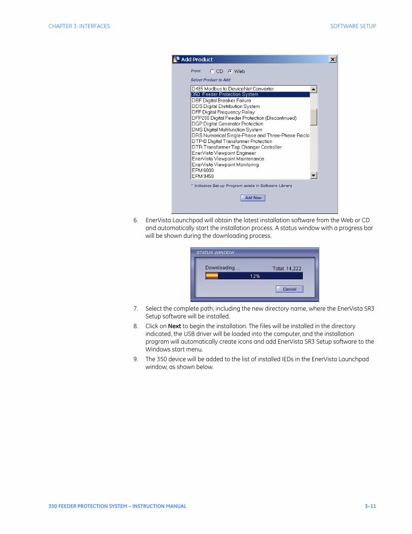
CHAPTER 3: INTERFACES SOFTWARE SETUP
350 FEEDER PROTECTION SYSTEM – INSTRUCTION MANUAL 3–11
6. EnerVista Launchpad will obtain the latest installation software from the Web or CD and automatically start the installation process. A status window with a progress bar will be shown during the downloading process.
7. Select the complete path, including the new directory name, where the EnerVista SR3 Setup software will be installed.
8. Click on Next to begin the installation. The files will be installed in the directory indicated, the USB driver will be loaded into the computer, and the installation program will automatically create icons and add EnerVista SR3 Setup software to the Windows start menu.
9. The 350 device will be added to the list of installed IEDs in the EnerVista Launchpad window, as shown below.
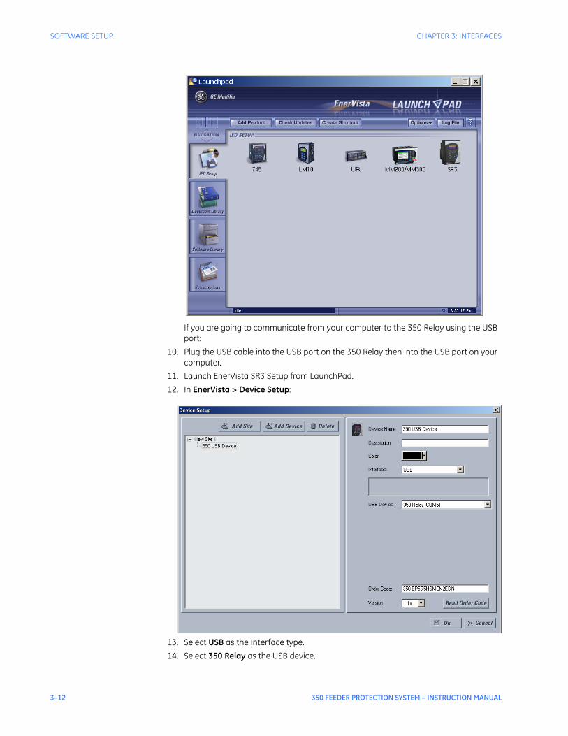
3–12 350 FEEDER PROTECTION SYSTEM – INSTRUCTION MANUAL
SOFTWARE SETUP CHAPTER 3: INTERFACES
If you are going to communicate from your computer to the 350 Relay using the USB port:
10. Plug the USB cable into the USB port on the 350 Relay then into the USB port on your computer.
11. Launch EnerVista SR3 Setup from LaunchPad.12. In EnerVista > Device Setup:
13. Select USB as the Interface type.14. Select 350 Relay as the USB device.
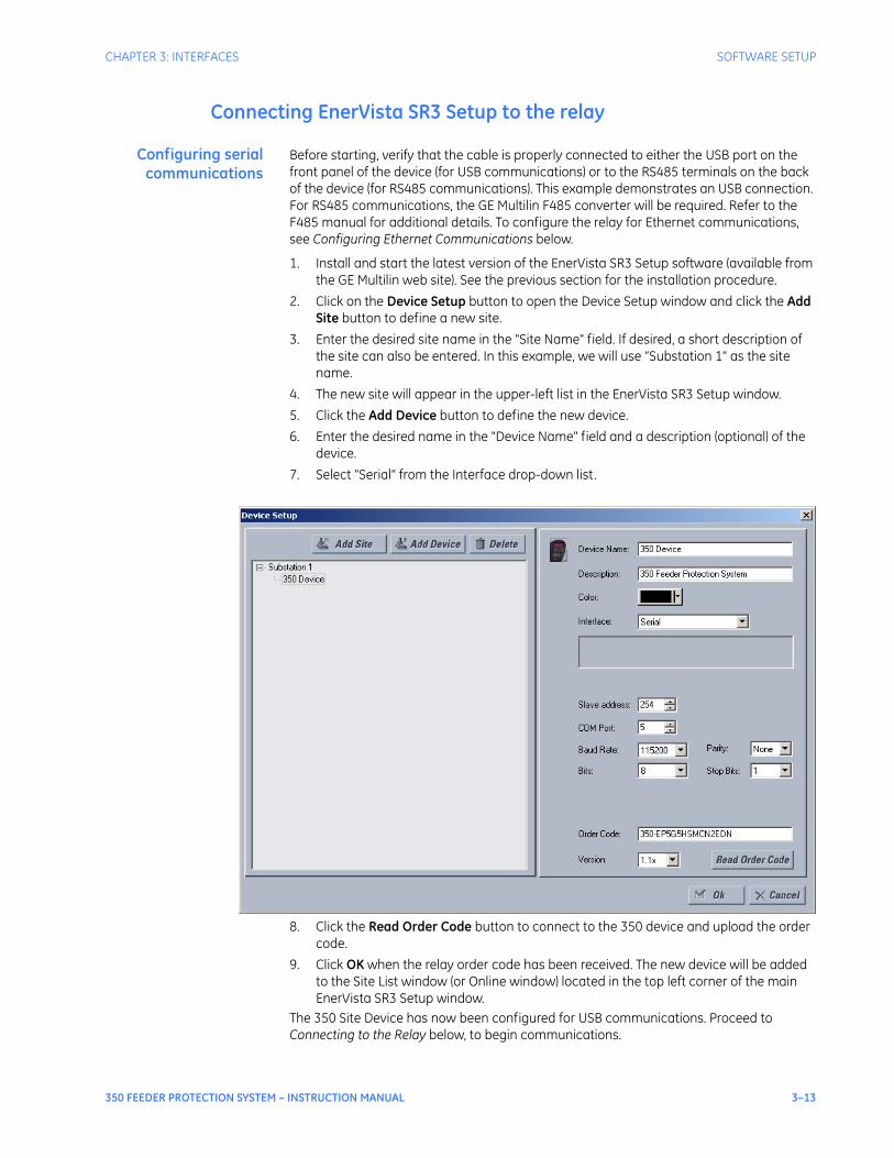
CHAPTER 3: INTERFACES SOFTWARE SETUP
350 FEEDER PROTECTION SYSTEM – INSTRUCTION MANUAL 3–13
Connecting EnerVista SR3 Setup to the relay
Configuring serialcommunications
Before starting, verify that the cable is properly connected to either the USB port on the front panel of the device (for USB communications) or to the RS485 terminals on the back of the device (for RS485 communications). This example demonstrates an USB connection. For RS485 communications, the GE Multilin F485 converter will be required. Refer to the F485 manual for additional details. To configure the relay for Ethernet communications, see Configuring Ethernet Communications below.
1. Install and start the latest version of the EnerVista SR3 Setup software (available from the GE Multilin web site). See the previous section for the installation procedure.
2. Click on the Device Setup button to open the Device Setup window and click the Add Site button to define a new site.
3. Enter the desired site name in the "Site Name" field. If desired, a short description of the site can also be entered. In this example, we will use “Substation 1” as the site name.
4. The new site will appear in the upper-left list in the EnerVista SR3 Setup window.5. Click the Add Device button to define the new device.6. Enter the desired name in the "Device Name" field and a description (optional) of the
device.7. Select “Serial” from the Interface drop-down list.
8. Click the Read Order Code button to connect to the 350 device and upload the order code.
9. Click OK when the relay order code has been received. The new device will be added to the Site List window (or Online window) located in the top left corner of the main EnerVista SR3 Setup window.
The 350 Site Device has now been configured for USB communications. Proceed to Connecting to the Relay below, to begin communications.
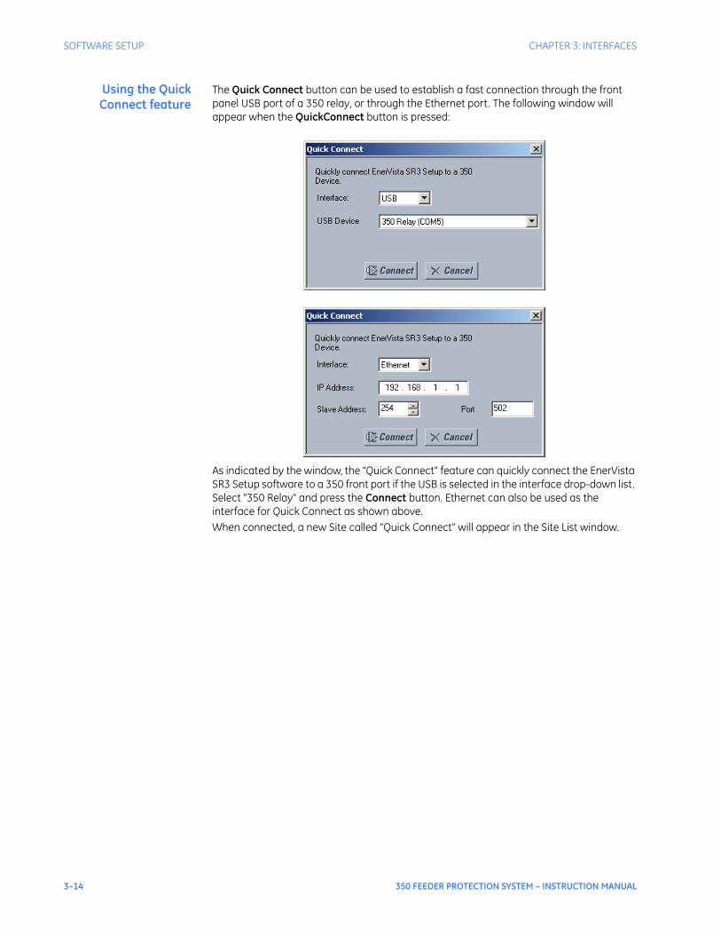
3–14 350 FEEDER PROTECTION SYSTEM – INSTRUCTION MANUAL
SOFTWARE SETUP CHAPTER 3: INTERFACES
Using the QuickConnect feature
The Quick Connect button can be used to establish a fast connection through the front panel USB port of a 350 relay, or through the Ethernet port. The following window will appear when the QuickConnect button is pressed:
As indicated by the window, the "Quick Connect" feature can quickly connect the EnerVista SR3 Setup software to a 350 front port if the USB is selected in the interface drop-down list. Select "350 Relay" and press the Connect button. Ethernet can also be used as the interface for Quick Connect as shown above.When connected, a new Site called “Quick Connect” will appear in the Site List window.
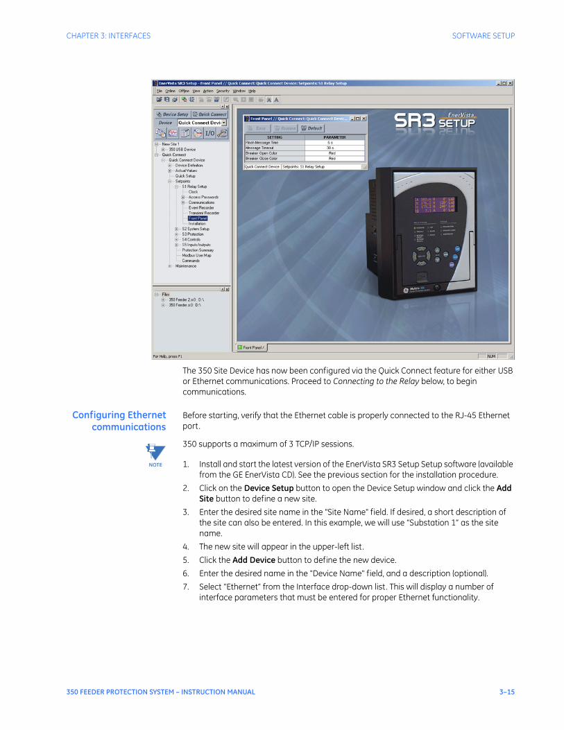
CHAPTER 3: INTERFACES SOFTWARE SETUP
350 FEEDER PROTECTION SYSTEM – INSTRUCTION MANUAL 3–15
The 350 Site Device has now been configured via the Quick Connect feature for either USB or Ethernet communications. Proceed to Connecting to the Relay below, to begin communications.
Configuring Ethernetcommunications
Before starting, verify that the Ethernet cable is properly connected to the RJ-45 Ethernet port.
NOTE
NOTE: 350 supports a maximum of 3 TCP/IP sessions.
1. Install and start the latest version of the EnerVista SR3 Setup Setup software (available from the GE EnerVista CD). See the previous section for the installation procedure.
2. Click on the Device Setup button to open the Device Setup window and click the Add Site button to define a new site.
3. Enter the desired site name in the "Site Name" field. If desired, a short description of the site can also be entered. In this example, we will use “Substation 1” as the site name.
4. The new site will appear in the upper-left list.5. Click the Add Device button to define the new device.6. Enter the desired name in the "Device Name" field, and a description (optional).7. Select “Ethernet” from the Interface drop-down list. This will display a number of
interface parameters that must be entered for proper Ethernet functionality.
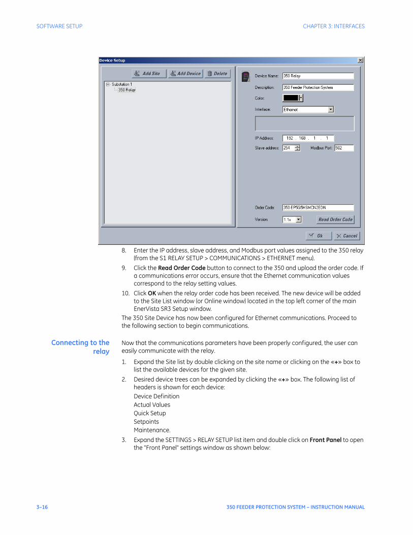
3–16 350 FEEDER PROTECTION SYSTEM – INSTRUCTION MANUAL
SOFTWARE SETUP CHAPTER 3: INTERFACES
8. Enter the IP address, slave address, and Modbus port values assigned to the 350 relay (from the S1 RELAY SETUP > COMMUNICATIONS > ETHERNET menu).
9. Click the Read Order Code button to connect to the 350 and upload the order code. If a communications error occurs, ensure that the Ethernet communication values correspond to the relay setting values.
10. Click OK when the relay order code has been received. The new device will be added to the Site List window (or Online window) located in the top left corner of the main EnerVista SR3 Setup window.
The 350 Site Device has now been configured for Ethernet communications. Proceed to the following section to begin communications.
Connecting to therelay
Now that the communications parameters have been properly configured, the user can easily communicate with the relay.
1. Expand the Site list by double clicking on the site name or clicking on the «+» box to list the available devices for the given site.
2. Desired device trees can be expanded by clicking the «+» box. The following list of headers is shown for each device:Device DefinitionActual ValuesQuick SetupSetpointsMaintenance.
3. Expand the SETTINGS > RELAY SETUP list item and double click on Front Panel to open the "Front Panel" settings window as shown below:

CHAPTER 3: INTERFACES SOFTWARE SETUP
350 FEEDER PROTECTION SYSTEM – INSTRUCTION MANUAL 3–17
4. The "Front Panel" settings window will open with a corresponding status indicator on the lower left of the EnerVista SR3 Setup window.
5. If the status indicator is red, verify that the serial, USB, or Ethernet cable is properly connected to the relay, and that the relay has been properly configured for communications (steps described earlier).
The "Front Panel" settings can now be edited, printed, or changed. Other setpoint and command windows can be displayed and edited in a similar manner. "Actual Values" windows are also available for display. These windows can be arranged, and resized at will.
Working with setpoints and setpoint files
Engaging a device The EnerVista SR3 Setup software may be used in on-line mode (relay connected) to directly communicate with a relay. Communicating relays are organized and grouped by communication interfaces and into sites. Sites may contain any number of relays selected from the product series.
Entering setpoints The System Setup page will be used as an example to illustrate the entering of setpoints. In this example, we will be changing the voltage sensing setpoints.
1. Establish communications with the relay.2. Select the Setpoint > System Setup > Voltage Sensing menu item.3. Select the Bus VT Secondary setpoint by clicking anywhere in the parameter box. This
will display three arrows: two to increment/decrement the value and another to launch the numerical keypad.
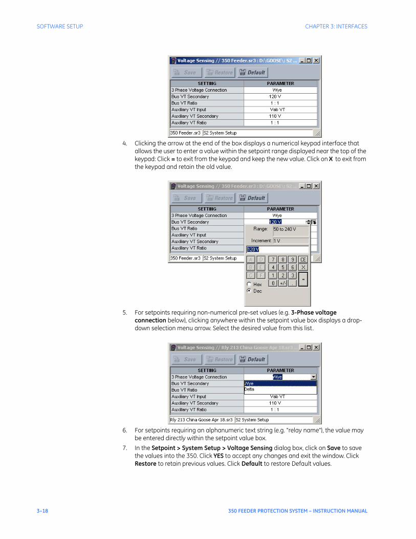
3–18 350 FEEDER PROTECTION SYSTEM – INSTRUCTION MANUAL
SOFTWARE SETUP CHAPTER 3: INTERFACES
4. Clicking the arrow at the end of the box displays a numerical keypad interface that allows the user to enter a value within the setpoint range displayed near the top of the keypad: Click = to exit from the keypad and keep the new value. Click on X to exit from the keypad and retain the old value.
5. For setpoints requiring non-numerical pre-set values (e.g. 3-Phase voltage connection below), clicking anywhere within the setpoint value box displays a drop-down selection menu arrow. Select the desired value from this list.
6. For setpoints requiring an alphanumeric text string (e.g. "relay name"), the value may be entered directly within the setpoint value box.
7. In the Setpoint > System Setup > Voltage Sensing dialog box, click on Save to save the values into the 350. Click YES to accept any changes and exit the window. Click Restore to retain previous values. Click Default to restore Default values.

CHAPTER 3: INTERFACES SOFTWARE SETUP
350 FEEDER PROTECTION SYSTEM – INSTRUCTION MANUAL 3–19
File support Opening any EnerVista SR3 Setup file will automatically launch the application or provide focus to the already opened application. If the file is a settings file (has a ‘SR3’ extension) which had been removed from the Settings List tree menu, it will be added back to the Settings List tree.New files will be automatically added to the tree.
Using setpoints files The EnerVista SR3 Setup software interface supports three ways of handling changes to relay settings:• In off-line mode (relay disconnected) to create or edit relay settings files for later
download to communicating relays.• Directly modifying relay settings while connected to a communicating relay, then
saving the settings when complete.• Creating/editing settings files while connected to a communicating relay, then saving
them to the relay when complete.Settings files are organized on the basis of file names assigned by the user. A settings file contains data pertaining to the following types of relay settings:• Device Definition• Relay Setup• System Setup• Protection• Control • Inputs/OutputsFactory default values are supplied and can be restored after any changes.The EnerVista SR3 Setup displays relay setpoints with the same hierarchy as the front panel display.
Downloading andsaving setpoints files
Setpoints must be saved to a file on the local PC before performing any firmware upgrades. Saving setpoints is also highly recommended before making any setpoint changes or creating new setpoint files.The setpoint files in the EnerVista SR3 Setup window are accessed in the Files Window. Use the following procedure to download and save setpoint files to a local PC.
1. Ensure that the site and corresponding device(s) have been properly defined and configured as shown in Connecting EnerVista SR3 Setup to the Relay, above.
2. Select the desired device from the site list.3. Select the Online > Read Device Settings from Device menu item, or right-click on the
device and select Read Device Settings to obtain settings information from the device.
4. After a few seconds of data retrieval, the software will request the name and destination path of the setpoint file. The corresponding file extension will be automatically assigned. Press Receive to complete the process. A new entry will be added to the tree, in the File pane, showing path and file name for the setpoint file.
Adding setpoints filesto the environment
The EnerVista SR3 Setup software provides the capability to review and manage a large group of setpoint files. Use the following procedure to add an existing file to the list.
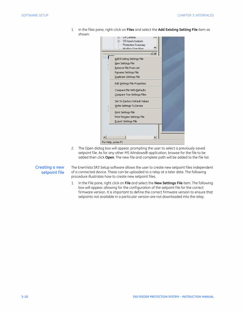
3–20 350 FEEDER PROTECTION SYSTEM – INSTRUCTION MANUAL
SOFTWARE SETUP CHAPTER 3: INTERFACES
1. In the files pane, right-click on Files and select the Add Existing Setting File item as shown:
2. The Open dialog box will appear, prompting the user to select a previously saved setpoint file. As for any other MS Windows® application, browse for the file to be added then click Open. The new file and complete path will be added to the file list.
Creating a newsetpoint file
The EnerVista SR3 Setup software allows the user to create new setpoint files independent of a connected device. These can be uploaded to a relay at a later date. The following procedure illustrates how to create new setpoint files.
1. In the File pane, right click on File and select the New Settings File item. The following box will appear, allowing for the configuration of the setpoint file for the correct firmware version. It is important to define the correct firmware version to ensure that setpoints not available in a particular version are not downloaded into the relay.

CHAPTER 3: INTERFACES SOFTWARE SETUP
350 FEEDER PROTECTION SYSTEM – INSTRUCTION MANUAL 3–21
2. Select the Firmware Version, and Order Code options for the new setpoint file.3. For future reference, enter some useful information in the Description box to facilitate
the identification of the device and the purpose of the file.4. To select a file name and path for the new file, click the button beside the File Name
box.5. Select the file name and path to store the file, or select any displayed file name to
replace an existing file. All 350 setpoint files should have the extension ‘SR3’ (for example, ‘feeder1.SR3’).
6. Click OK to complete the process. Once this step is completed, the new file, with a complete path, will be added to the EnerVista SR3 Setup software environment.
Upgrading setpointfiles to a new revision
It is often necessary to upgrade the revision for a previously saved setpoint file after the 350 firmware has been upgraded. This is illustrated in the following procedure:
1. Establish communications with the 350 relay.2. Select the Maintenance > M1 Relay Info menu item and record the Firmware
Revision.3. Load the setpoint file to be upgraded into the EnerVista SR3 Setup environment as
described in the section, Adding Setpoints Files to the Environment.4. In the File pane, select the saved setpoint file.5. From the main window menu bar, select the Offline > Edit Settings File Properties
menu item and note the File Version of the setpoint file. If this version is different from the Firmware Revision noted in step 2, select a New File Version that matches the Firmware Revision from the pull-down menu.
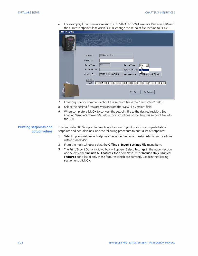
3–22 350 FEEDER PROTECTION SYSTEM – INSTRUCTION MANUAL
SOFTWARE SETUP CHAPTER 3: INTERFACES
6. For example, if the firmware revision is L0L01MA140.000 (Firmware Revision 1.40) and the current setpoint file revision is 1.20, change the setpoint file revision to “1.4x”.
7. Enter any special comments about the setpoint file in the "Description" field.8. Select the desired firmware version from the "New File Version" field.9. When complete, click OK to convert the setpoint file to the desired revision. See
Loading Setpoints from a File below, for instructions on loading this setpoint file into the 350.
Printing setpoints andactual values
The EnerVista SR3 Setup software allows the user to print partial or complete lists of setpoints and actual values. Use the following procedure to print a list of setpoints:
1. Select a previously saved setpoints file in the File pane or establish communications with a 350 device.
2. From the main window, select the Offline > Export Settings File menu item.3. The Print/Export Options dialog box will appear. Select Settings in the upper section
and select either Include All Features (for a complete list) or Include Only Enabled Features (for a list of only those features which are currently used) in the filtering section and click OK.

CHAPTER 3: INTERFACES SOFTWARE SETUP
350 FEEDER PROTECTION SYSTEM – INSTRUCTION MANUAL 3–23
4. The process for Offline > Print Preview Settings File is identical to the steps above.5. Setpoint lists can be printed in the same manner by right clicking on the desired file (in
the file list) or device (in the device list) and selecting the Print Device Information or Print Settings File options.
Printing actual valuesfrom a connected
device
A complete list of actual values can also be printed from a connected device with the following procedure:
1. Establish communications with the desired 350 device.2. From the main window, select the Online > Print Device Information menu item3. The Print/Export Options dialog box will appear. Select Actual Values in the upper
section and select either Include All Features (for a complete list) or Include Only Enabled Features (for a list of only those features which are currently used) in the filtering section and click OK.
Actual values lists can be printed in the same manner by right clicking on the desired device (in the device list) and selecting the Print Device Information option
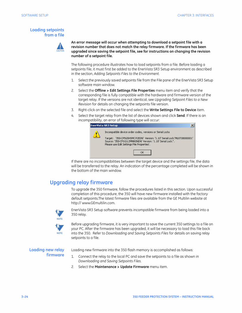
3–24 350 FEEDER PROTECTION SYSTEM – INSTRUCTION MANUAL
SOFTWARE SETUP CHAPTER 3: INTERFACES
Loading setpointsfrom a file
CAUTION
CAUTION: An error message will occur when attempting to download a setpoint file with a revision number that does not match the relay firmware. If the firmware has been upgraded since saving the setpoint file, see for instructions on changing the revision number of a setpoint file.
The following procedure illustrates how to load setpoints from a file. Before loading a setpoints file, it must first be added to the EnerVista SR3 Setup environment as described in the section, Adding Setpoints Files to the Environment.
1. Select the previously saved setpoints file from the File pane of the EnerVista SR3 Setup software main window.
2. Select the Offline > Edit Settings File Properties menu item and verify that the corresponding file is fully compatible with the hardware and firmware version of the target relay. If the versions are not identical, see Upgrading Setpoint Files to a New Revision for details on changing the setpoints file version.
3. Right-click on the selected file and select the Write Settings File to Device item.4. Select the target relay from the list of devices shown and click Send. If there is an
incompatibility, an error of following type will occur:
If there are no incompatibilities between the target device and the settings file, the data will be transferred to the relay. An indication of the percentage completed will be shown in the bottom of the main window.
Upgrading relay firmwareTo upgrade the 350 firmware, follow the procedures listed in this section. Upon successful completion of this procedure, the 350 will have new firmware installed with the factory default setpoints.The latest firmware files are available from the GE Multilin website at http:// www.GEmultilin.com.
NOTE
NOTE: EnerVista SR3 Setup software prevents incompatible firmware from being loaded into a 350 relay.
NOTE
NOTE: Before upgrading firmware, it is very important to save the current 350 settings to a file on your PC. After the firmware has been upgraded, it will be necessary to load this file back into the 350. Refer to Downloading and Saving Setpoints Files for details on saving relay setpoints to a file.
Loading new relayfirmware
Loading new firmware into the 350 flash memory is accomplished as follows:
1. Connect the relay to the local PC and save the setpoints to a file as shown in Downloading and Saving Setpoints Files.
2. Select the Maintenance > Update Firmware menu item.
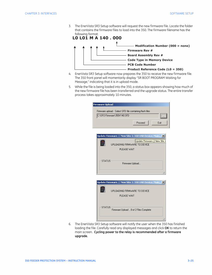
CHAPTER 3: INTERFACES SOFTWARE SETUP
350 FEEDER PROTECTION SYSTEM – INSTRUCTION MANUAL 3–25
3. The EnerVista SR3 Setup software will request the new firmware file. Locate the folder that contains the firmware files to load into the 350. The firmware filename has the following format:
4. EnerVista SR3 Setup software now prepares the 350 to receive the new firmware file. The 350 front panel will momentarily display "SR BOOT PROGRAM Waiting for Message,” indicating that it is in upload mode.
5. While the file is being loaded into the 350, a status box appears showing how much of the new firmware file has been transferred and the upgrade status. The entire transfer process takes approximately 10 minutes.
6. The EnerVista SR3 Setup software will notify the user when the 350 has finished loading the file. Carefully read any displayed messages and click OK to return the main screen. Cycling power to the relay is recommended after a firmware upgrade.
L0 L01 M A 140 . 000
Modification Number (000 = none)
Board Assembly Rev #
Code Type in Memory Device
PCB Code Number
Product Reference Code (L0 = 350)
Firmware Rev #

3–26 350 FEEDER PROTECTION SYSTEM – INSTRUCTION MANUAL
SOFTWARE SETUP CHAPTER 3: INTERFACES
After successfully updating the 350 firmware, the relay will not be in service and will require setpoint programming. To communicate with the relay, the communication settings may have to be manually reprogrammed.When communications is established, the saved setpoints must be reloaded back into the relay. See Loading Setpoints from a File for details.Modbus addresses assigned to firmware modules, features, settings, and corresponding data items (i.e. default values, min/max values, data type, and item size) may change slightly from version to version of firmware.The addresses are rearranged when new features are added or existing features are enhanced or modified.
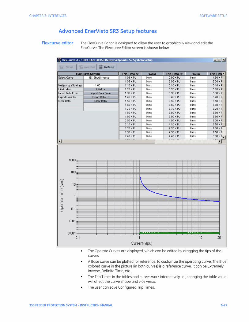
CHAPTER 3: INTERFACES SOFTWARE SETUP
350 FEEDER PROTECTION SYSTEM – INSTRUCTION MANUAL 3–27
Advanced EnerVista SR3 Setup features
Flexcurve editor The FlexCurve Editor is designed to allow the user to graphically view and edit the FlexCurve. The Flexcurve Editor screen is shown below:
• The Operate Curves are displayed, which can be edited by dragging the tips of the curves
• A Base curve can be plotted for reference, to customize the operating curve. The Blue colored curve in the picture (in both curves) is a reference curve. It can be Extremely Inverse, Definite Time, etc.
• The Trip Times in the tables and curves work interactively i.e., changing the table value will affect the curve shape and vice versa.
• The user can save Configured Trip Times.
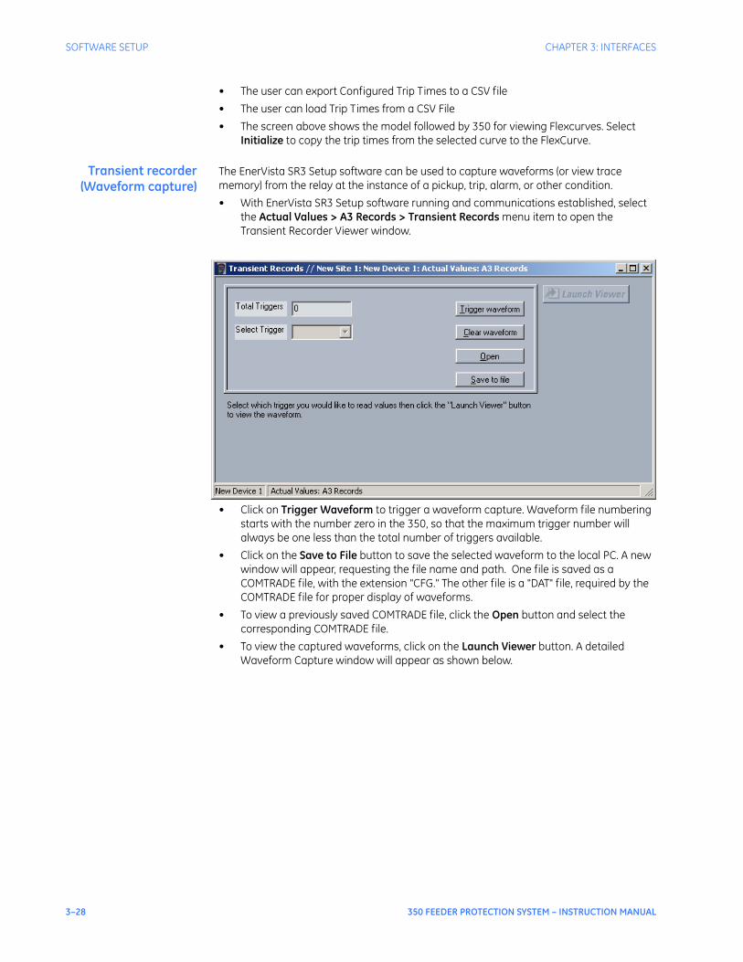
3–28 350 FEEDER PROTECTION SYSTEM – INSTRUCTION MANUAL
SOFTWARE SETUP CHAPTER 3: INTERFACES
• The user can export Configured Trip Times to a CSV file• The user can load Trip Times from a CSV File• The screen above shows the model followed by 350 for viewing Flexcurves. Select
Initialize to copy the trip times from the selected curve to the FlexCurve.
Transient recorder(Waveform capture)
The EnerVista SR3 Setup software can be used to capture waveforms (or view trace memory) from the relay at the instance of a pickup, trip, alarm, or other condition.• With EnerVista SR3 Setup software running and communications established, select
the Actual Values > A3 Records > Transient Records menu item to open the Transient Recorder Viewer window.
• Click on Trigger Waveform to trigger a waveform capture. Waveform file numbering starts with the number zero in the 350, so that the maximum trigger number will always be one less than the total number of triggers available.
• Click on the Save to File button to save the selected waveform to the local PC. A new window will appear, requesting the file name and path. One file is saved as a COMTRADE file, with the extension "CFG." The other file is a "DAT" file, required by the COMTRADE file for proper display of waveforms.
• To view a previously saved COMTRADE file, click the Open button and select the corresponding COMTRADE file.
• To view the captured waveforms, click on the Launch Viewer button. A detailed Waveform Capture window will appear as shown below.
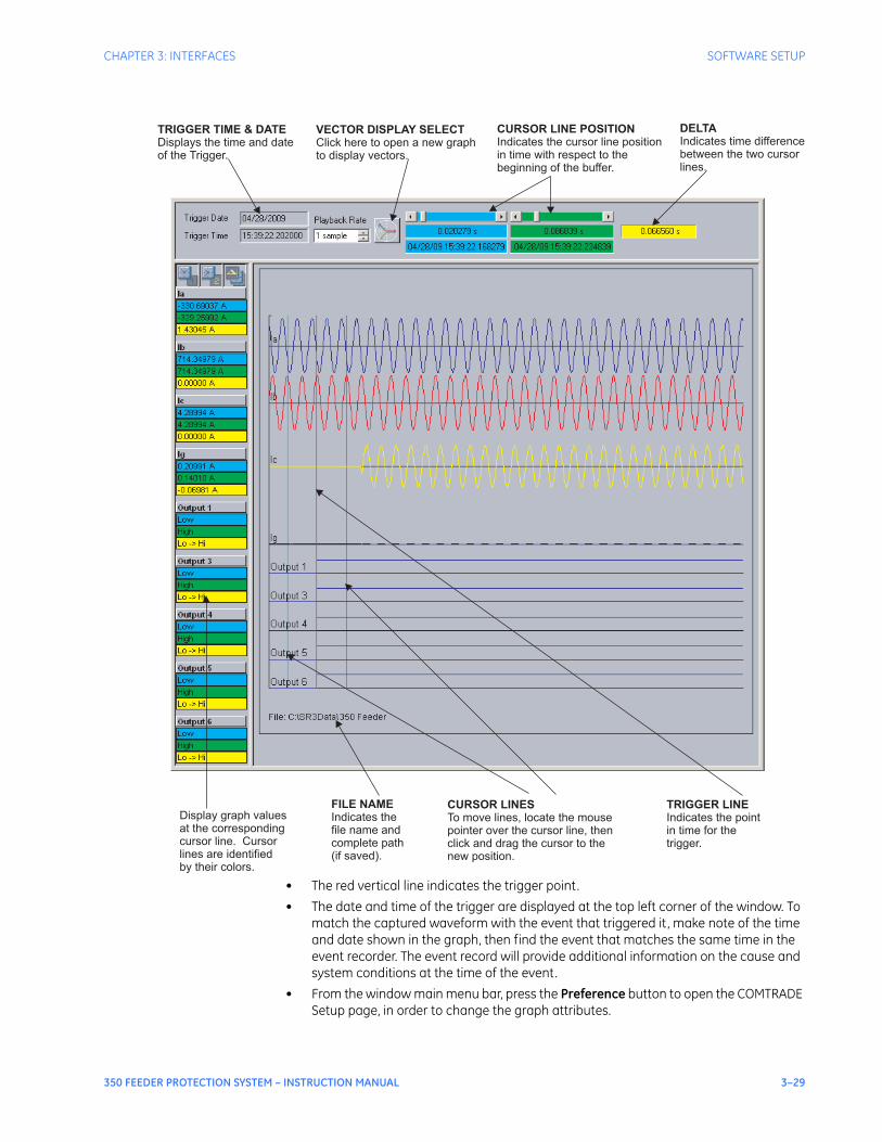
CHAPTER 3: INTERFACES SOFTWARE SETUP
350 FEEDER PROTECTION SYSTEM – INSTRUCTION MANUAL 3–29
• The red vertical line indicates the trigger point.• The date and time of the trigger are displayed at the top left corner of the window. To
match the captured waveform with the event that triggered it , make note of the time and date shown in the graph, then find the event that matches the same time in the event recorder. The event record will provide additional information on the cause and system conditions at the time of the event.
• From the window main menu bar, press the Preference button to open the COMTRADE Setup page, in order to change the graph attributes.
Display graph values
at the corresponding
cursor line. Cursor
lines are identified
by their colors.
FILE NAME
Indicates the
file name and
complete path
(if saved).
CURSOR LINES
To move lines, locate the mouse
pointer over the cursor line, then
click and drag the cursor to the
new position.
TRIGGER LINE
Indicates the point
in time for the
trigger.
TRIGGER TIME & DATE
Displays the time and date
of the Trigger.
VECTOR DISPLAY SELECT
Click here to open a new graph
to display vectors.
CURSOR LINE POSITION
Indicates the cursor line position
in time with respect to the
beginning of the buffer.
DELTA
Indicates time difference
between the two cursor
lines.
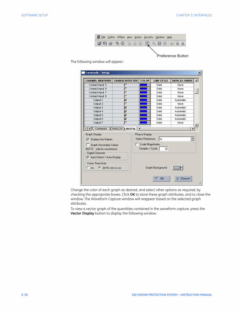
3–30 350 FEEDER PROTECTION SYSTEM – INSTRUCTION MANUAL
SOFTWARE SETUP CHAPTER 3: INTERFACES
The following window will appear:
Change the color of each graph as desired, and select other options as required, by checking the appropriate boxes. Click OK to store these graph attributes, and to close the window. The Waveform Capture window will reappear based on the selected graph attributes.To view a vector graph of the quantities contained in the waveform capture, press the Vector Display button to display the following window:
Preference Button
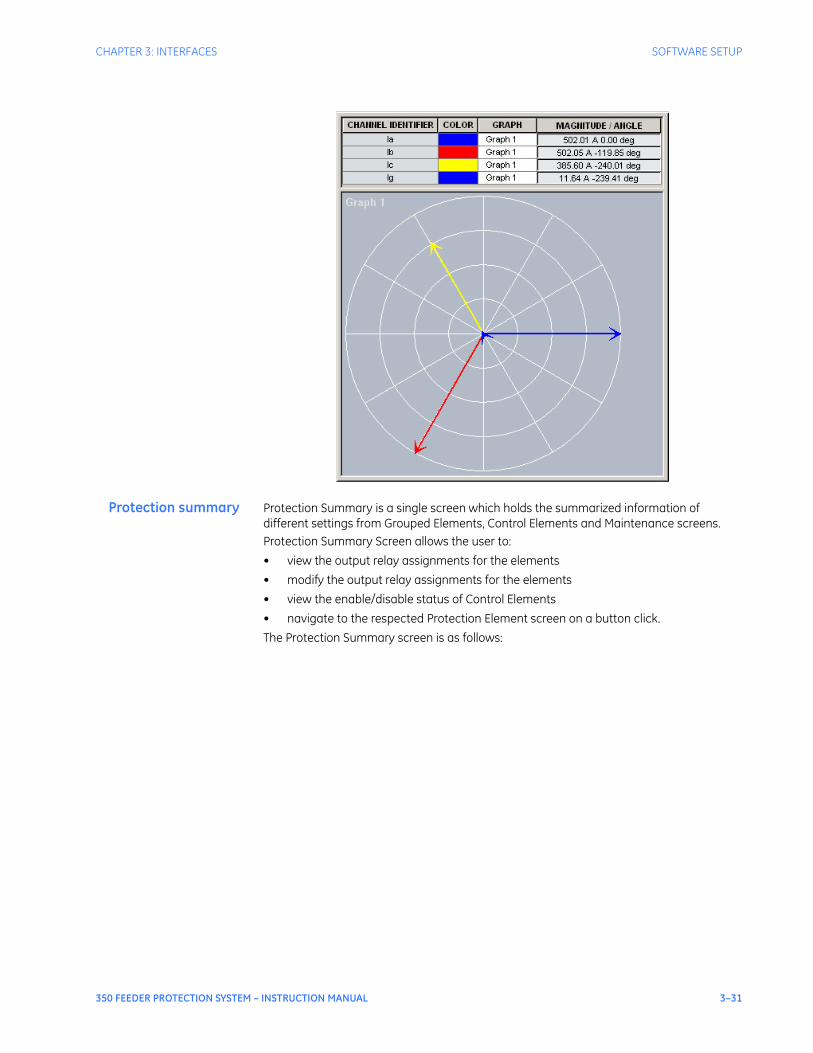
CHAPTER 3: INTERFACES SOFTWARE SETUP
350 FEEDER PROTECTION SYSTEM – INSTRUCTION MANUAL 3–31
Protection summary Protection Summary is a single screen which holds the summarized information of different settings from Grouped Elements, Control Elements and Maintenance screens.Protection Summary Screen allows the user to:• view the output relay assignments for the elements• modify the output relay assignments for the elements• view the enable/disable status of Control Elements• navigate to the respected Protection Element screen on a button click.The Protection Summary screen is as follows:
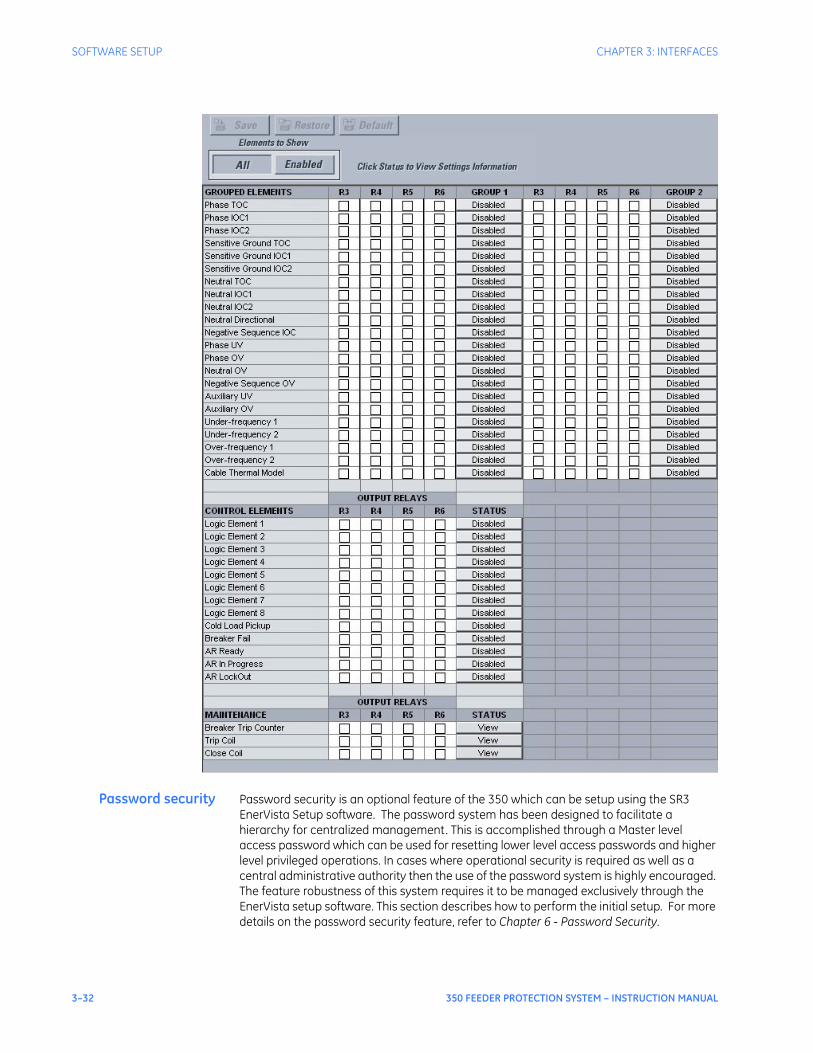
3–32 350 FEEDER PROTECTION SYSTEM – INSTRUCTION MANUAL
SOFTWARE SETUP CHAPTER 3: INTERFACES
Password security Password security is an optional feature of the 350 which can be setup using the SR3 EnerVista Setup software. The password system has been designed to facilitate a hierarchy for centralized management. This is accomplished through a Master level access password which can be used for resetting lower level access passwords and higher level privileged operations. In cases where operational security is required as well as a central administrative authority then the use of the password system is highly encouraged. The feature robustness of this system requires it to be managed exclusively through the EnerVista setup software. This section describes how to perform the initial setup. For more details on the password security feature, refer to Chapter 6 - Password Security.
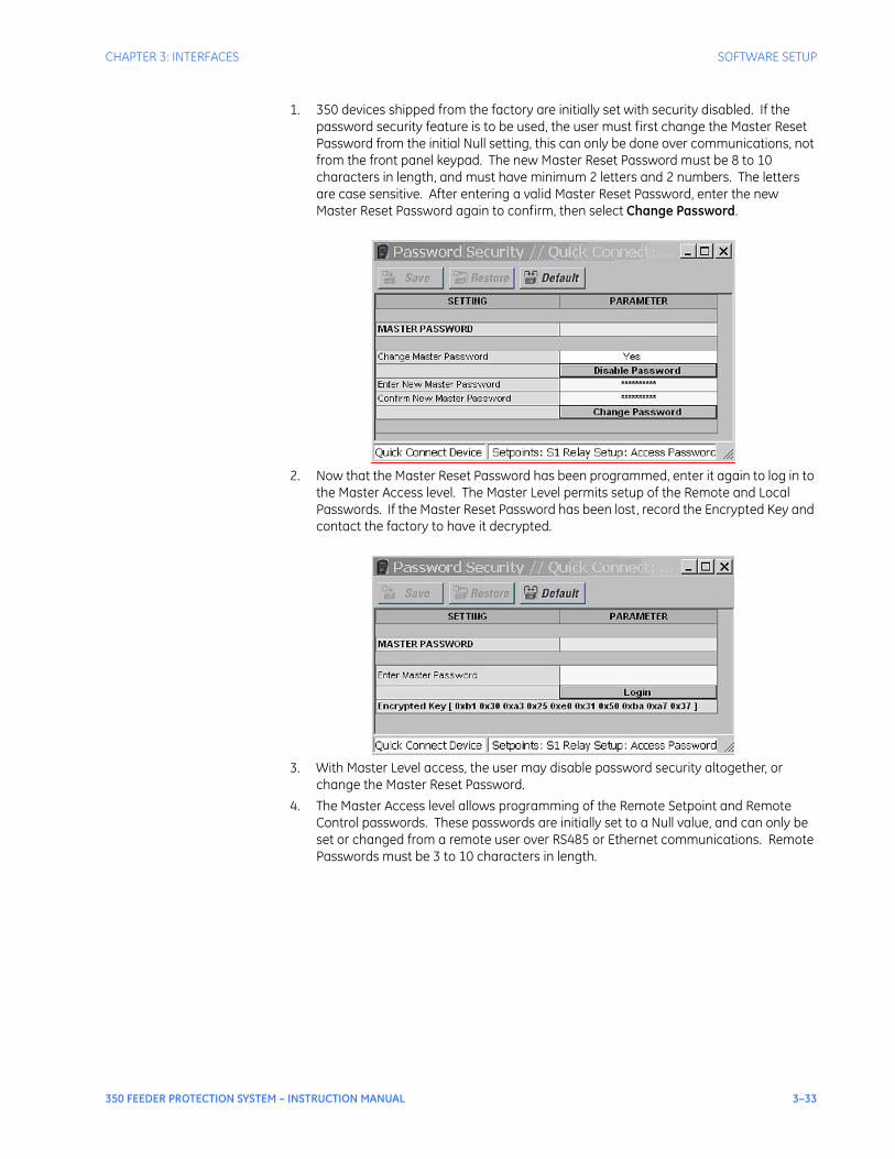
CHAPTER 3: INTERFACES SOFTWARE SETUP
350 FEEDER PROTECTION SYSTEM – INSTRUCTION MANUAL 3–33
1. 350 devices shipped from the factory are initially set with security disabled. If the password security feature is to be used, the user must first change the Master Reset Password from the initial Null setting, this can only be done over communications, not from the front panel keypad. The new Master Reset Password must be 8 to 10 characters in length, and must have minimum 2 letters and 2 numbers. The letters are case sensitive. After entering a valid Master Reset Password, enter the new Master Reset Password again to confirm, then select Change Password.
2. Now that the Master Reset Password has been programmed, enter it again to log in to the Master Access level. The Master Level permits setup of the Remote and Local Passwords. If the Master Reset Password has been lost, record the Encrypted Key and contact the factory to have it decrypted.
3. With Master Level access, the user may disable password security altogether, or change the Master Reset Password.
4. The Master Access level allows programming of the Remote Setpoint and Remote Control passwords. These passwords are initially set to a Null value, and can only be set or changed from a remote user over RS485 or Ethernet communications. Remote Passwords must be 3 to 10 characters in length.
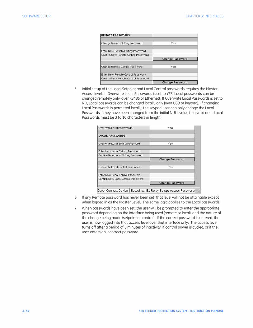
3–34 350 FEEDER PROTECTION SYSTEM – INSTRUCTION MANUAL
SOFTWARE SETUP CHAPTER 3: INTERFACES
5. Initial setup of the Local Setpoint and Local Control passwords requires the Master Access level. If Overwrite Local Passwords is set to YES, Local passwords can be changed remotely only (over RS485 or Ethernet). If Overwrite Local Passwords is set to NO, Local passwords can be changed locally only (over USB or keypad). If changing Local Passwords is permitted locally, the keypad user can only change the Local Passwords if they have been changed from the initial NULL value to a valid one. Local Passwords must be 3 to 10 characters in length.
6. If any Remote password has never been set, that level will not be attainable except when logged in as the Master Level. The same logic applies to the Local passwords.
7. When passwords have been set, the user will be prompted to enter the appropriate password depending on the interface being used (remote or local), and the nature of the change being made (setpoint or control). If the correct password is entered, the user is now logged into that access level over that interface only. The access level turns off after a period of 5 minutes of inactivity, if control power is cycled, or if the user enters an incorrect password.
350 FEEDER PROTECTION SYSTEM – INSTRUCTION MANUAL 4–1
350 Feeder Protection System
Chapter 4: Actual values
Digital EnergyMultilin
Actual values
Actual values overview
All measured values, the status of digital inputs and outputs, and fault analysis information are accessed in Actual Values mode. Actual value messages are organized into logical groups for easy reference as shown below.
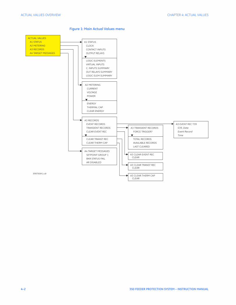
4–2 350 FEEDER PROTECTION SYSTEM – INSTRUCTION MANUAL
ACTUAL VALUES OVERVIEW CHAPTER 4: ACTUAL VALUES
Figure 1: Main Actual Values menu
A2 METERING
CURRENT
VOLTAGE
POWER
ENERGY
THERMAL CAP
CLEAR ENERGY
▼
A1 STATUS
CLOCK
CONTACT INPUTS
OUTPUT RELAYS
LOGIC ELEMENTS
VIRTUAL INPUTS
C. INPUTS SUMMARY
OUT RELAYS SUMMARY
LOGIC ELEM SUMMARY
▼
ACTUAL VALUES
A1 STATUS
A2 METERING
A3 RECORDS
A4 TARGET MESSAGES
898760A1.cdr
A3 RECORDS
EVENT RECORDS
TRANSIENT RECORDS
CLEAR EVENT REC
CLEAR TRANST REC
CLEAR THERM CAP
▼
A3 TRANSIENT RECORDS
FORCE TRIGGER?
TOTAL RECORDS
AVAILABLE RECORDS
LAST CLEARED
▼
A3 EVENT REC T39
E39, Date
Event Record
Time
A3 CLEAR TRANST RECCLEAR
A3 CLEAR EVENT RECCLEAR
A4 TARGET MESSAGES
SETPOINT GROUP 1
BKR STATUS FAIL
AR DISABLED
A3 CLEAR THERM CAPCLEAR
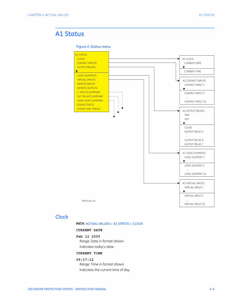
CHAPTER 4: ACTUAL VALUES A1 STATUS
350 FEEDER PROTECTION SYSTEM – INSTRUCTION MANUAL 4–3
A1 Status
Figure 2: Status menu
ClockPATH: ACTUAL VALUES > A1 STATUS > CLOCK
CURRENT DATE
Feb 12 2009
Range: Date in format shown
Indicates today’s date.
CURRENT TIME
09:17:12
Range: Time in format shown
Indicates the current time of day.
A1 CONTACT INPUTS
CONTACT INPUT 1
CONTACT INPUT 2
...
CONTACT INPUT 10
▼
A1 CLOCK
CURRENT DATE
CURRENT TIME
▼
A1 STATUS
CLOCK
CONTACT INPUTS
OUTPUT RELAYS
LOGIC ELEMENTS
VIRTUAL INPUTS
REMOTE INPUTS
REMOTE OUTPUTS
C. INPUTS SUMMARY
OUT RELAYS SUMMARY
LOGIC ELEM SUMMARY
GOOSE STATUS
GOOSE HDR. STATUS
▼
898763A1.cdr
A1 OUTPUT RELAYS
TRIP
OFF
CLOSE
OUTPUT RELAY 3
...
OUTPUT RELAY 6
OUTPUT RELAY 7
▼
A1 LOGIC ELEMENTS
LOGIC ELEMENT 1
2
...
16
LOGIC ELEMENT
LOGIC ELEMENT
▼
A1 VIRTUAL INPUTS
1
2
...
32
VIRTUAL INPUT
VIRTUAL INPUT
VIRTUAL INPUT
▼
4–4 350 FEEDER PROTECTION SYSTEM – INSTRUCTION MANUAL
A1 STATUS CHAPTER 4: ACTUAL VALUES
Contact inputsPATH: ACTUAL VALUES > A1 STATUS > CONTACT INPUTS
CI #1 (52a) (Contact Input 1)
OFF
Range: Off, On
The status of this contact shows the breaker close/open state, when wired to a 52a breaker auxiliary contact.
CI #2 (52b) (Contact Input 2)
OFF
Range: Off, On
The status of this contact shows the breaker close/open state, when wired to a 52b breaker auxiliary contact.
CONTACT INPUT 3 to 10
OFF
Range: Off, On
Message displays the state of the contact input. The message “ON” indicates that the contact input is energized, and message “OFF” indicates a de-energized contact.
Output relaysPATH: ACTUAL VALUES > A1 STATUS > OUTPUT RELAYS
TRIP (Output Relay #1)
OFF
Range: Off, On
The “ON” state of Output Relay #1 (TRIP) shows that a TRIP command has been sent to the breaker.
CLOSE (Output Relay #2)
OFF
Range: Off, On
The “ON” state of Output Relay #2 (CLOSE) shows that a close command has been sent to the breaker.
OUTPUT RELAY 3 to 6 (Auxiliary Output Relays)
OFF
Range: Off, On
OUTPUT RELAY 7 (Critical Failure Relay)Range: Off, On
The "ON" state indicates that the relay is in-service.
Logic elementsPATH: ACTUAL VALUES > A1 STATUS > LOGIC ELEMENTS
LOGIC ELEMENT 1 to 16
OFF
Range: Off, On
The state “ON” or “OFF” for each logic element depends on its programmed logic: triggering inputs, blocking inputs, plus any pickup, and/or reset time delay.
CHAPTER 4: ACTUAL VALUES A1 STATUS
350 FEEDER PROTECTION SYSTEM – INSTRUCTION MANUAL 4–5
Virtual inputsThe state of all active virtual inputs is displayed here. PATH: ACTUAL VALUES > A1 STATUS > VIRTUAL INPUTS
VIRTUAL INPUTS 1 to 32
OFF
Range: Off, On
Remote inputsThe state of all active remote inputs is displayed here. PATH: ACTUAL VALUES > A1 STATUS > REMOTE INPUTS
REMOTE INPUTS 1 to 32
OFF
Range: Off, On
Remote outputsThe state of all active remote outputs is displayed here. PATH: ACTUAL VALUES > A1 STATUS > REMOTE OUTPUTS
REMOTE OUTPUTS 1 to 32
OFF
Range: Off, On
Contact inputs summaryC. INPUTS SUMMARY
The display shows a summary of the states of all contact inputs.
Output relays summaryPATH: ACTUAL VALUES > A1 STATUS > OUT RELAYS SUMMARY
OUTPUT RELAYS SUMMARY
This display shows a summary of the states of all output relays.
52a OFF CI#6 OFF
52b OFF CI#7 OFF
CI#3 OFF CI#8 OFF
CI#4 OFF CI#9 OFF
CI#5 OFF CI#10 OFF
TRIP OFF RLY#5 OFF
CLOSE OFF RLY#6 OFF
RLY#3 OFF RLY#7 ON
RLY#4 OFF
4–6 350 FEEDER PROTECTION SYSTEM – INSTRUCTION MANUAL
A1 STATUS CHAPTER 4: ACTUAL VALUES
NOTE
NOTE: Output relay #7 is the Critical Failure relay, used to indicate the correct functioning of the 350 relay. This output relay shows the status "ON" when the 350 relay is powered up and set to "Ready" and no self-test alarms are active, under SETPOINTS > S1 RELAY SETUP > S1 INSTALLATION > RELAY STATUS.
Logic elements summaryPATH: ACTUAL VALUES > A1 STATUS > LOGIC ELEM SUMMARY
LOGIC ELEM SUMMARY
This display shows a summary of the states of all logic elements.
GOOSE statusPATH: ACTUAL VALUES > A1 STATUS > GOOSE STATUS
GOOSE 1 TO 8 STATUS
Range: OFF, ONDefault: OFF
GOOSE HDR statusPATH: ACTUAL VALUES > A1 STATUS > GOOSE HDR STATUS
GOOSE 1 TO 8 H.STATUS
Range: OFF, ONDefault: OFF
LE#1 OFF LE#9 OFF
LE#2 OFF LE#10 OFF
LE#3 OFF LE#11 OFF
LE#4 OFF LE#12 OFF
LE#5 OFF LE#13 OFF
LE#6 OFF LE#14 OFF
LE#7 OFF LE#15 OFF
LE#8 OFF LE#16 OFF
CHAPTER 4: ACTUAL VALUES A2 METERING
350 FEEDER PROTECTION SYSTEM – INSTRUCTION MANUAL 4–7
A2 Metering
The relay measures all RMS currents and voltages, frequency, and all auxiliary analog inputs. Other values like neutral current, symmetrical components, power factor, power (real, reactive, apparent), are derived. All quantities are recalculated every power system cycle and perform protection and monitoring functions. Displayed metered quantities are updated approximately three (3) times a second for readability. All phasors and symmetrical components are referenced to the A-N voltage phasor for wye-connected VTs; to the A-B voltage phasor for delta connected VTs; or to the phase A current phasor when no voltage signals are present.By scrolling the Up/Down keys the relay shows one-by-one, all metered values as follows:
CurrentPH A CURRENT
0.0 A 0o lag
Range: 0.0 to 30000 A, 0 to 359o lag
PH B CURRENT
0.0 A 0o lag
Range: 0.0 to 30000 A, 0 to 359o lag
PH C CURRENT
0.0 A 0o lag
Range: 0.0 to 30000 A, 0 to 359o lag
NTRL CURRENT
0.0 A 0o lag
Range: 0.0 to 30000 A, 0 to 359o lag
GND CURRENT
0.0 A 0o lag
Range: 0.0 to 30000 A, 0 to 359o lag
GND CURRENT is shown when the GROUND CT TYPE is set to "1A Secondary" or "5A Secondary".
SENS GND CURRENT
0.00 A 0o lag
Range: 0.00 to 15.00 A, 0 to 359o lag
SENS GND CURRENT is shown when the GROUND CT TYPE is set to "50:0.025".

4–8 350 FEEDER PROTECTION SYSTEM – INSTRUCTION MANUAL
A2 METERING CHAPTER 4: ACTUAL VALUES
NEG SEQ CURRENT
0.0 A 0o lag
Range: 0.0 to 30000 A, 0 to 359o lag
VoltageAN VOLTAGE
0 V 0o lag
Range: 0 to 65535 V
BN VOLTAGE
0 V 0o lag
Range: 0 to 65535 V
CN VOLTAGE
0 V 0o lag
Range: 0 to 65535 V
AB VOLTAGE
0 V 0o lag
Range: 0 to 65535 V
BC VOLTAGE
0 V 0o lag
Range: 0 to 65535 V
CA VOLTAGE
0 V 0o lag
Range: 0 to 65535 V
NTRL VOLTAGE
0 V 0o lag
Range: 0 to 65535 V
NEG SEQ VOLTAGE
0 V 0o lag
Range: 0 to 65535 V
ZERO SEQ VOLTAGE
0 V 0o lag
Range: 0 to 65535 V
AUX VOLTAGE
0 V 0o lag
Range: 0 to 65535 V
FREQUENCY
0.00 Hz
Range: 40 to 70 Hz
Power3 ph REAL POWER
0.0 kV
CHAPTER 4: ACTUAL VALUES A2 METERING
350 FEEDER PROTECTION SYSTEM – INSTRUCTION MANUAL 4–9
Range: -100000.0 to 100000.0 kW
3 ph REACTIVE POWER
0.0 kVAR
Range: -100000.0 to 100000.0 kVAR
3 ph APPARENT POWER
0.0 kVA
Range: 0 to 3000 kVA
POWER FACTOR
0.00
Range: -0.99 to 1.00
EnergyPOSITIVE WATTHOUR
0.000 MWh
Range: 0.000 to 50000.000 MWh
NEGATIVE WATTHOUR
0.000 MWh
Range: 0.000 to 50000.000 MWh
POSITIVE VARHOUR
0.000 MVarh
Range: 0.000 to 50000.000 MVarh
NEGATIVE VARHOUR
0.000 MVarh
Range: 0.000 to 50000.000 MVarh
Thermal capacityTHERMAL CAP PH A
0%
THERMAL CAP PH B
0%
THERMAL CAP PH C
0%
Clear energyCLEAR ENERGY
NO
Range: No, Yes
When set to "YES," pressing the ENTER key will clear all energy data.
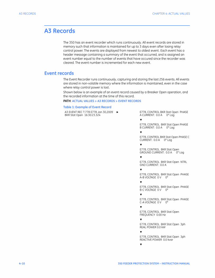
4–10 350 FEEDER PROTECTION SYSTEM – INSTRUCTION MANUAL
A3 RECORDS CHAPTER 4: ACTUAL VALUES
A3 Records
The 350 has an event recorder which runs continuously. All event records are stored in memory such that information is maintained for up to 3 days even after losing relay control power. The events are displayed from newest to oldest event. Each event has a header message containing a summary of the event that occurred, and is assigned an event number equal to the number of events that have occured since the recorder was cleared. The event number is incremented for each new event.
Event recordsThe Event Recorder runs continuously, capturing and storing the last 256 events. All events are stored in non-volatile memory where the information is maintained, even in the case where relay control power is lost. Shown below is an example of an event record caused by a Breaker Open operation, and the recorded information at the time of this record.PATH: ACTUAL VALUES > A3 RECORDS > EVENT RECORDS
Table 1: Example of Event RecordA3 EVENT REC T:778 E778 Jan 30,2009 BKR Stat Open 16:30:23.324
▶ E778, CONTROL BKR Stat Open PHASE A CURRENT: 0.0 A 0° Lag
▼E778, CONTROL BKR Stat Open PHASE B CURRENT: 0.0 A 0° Lag
▼E778, CONTROL BKR Stat Open PHASE C CURRENT: 0.0 A 0° Lag
▼E778, CONTROL BKR Stat Open GROUND CURRENT: 0.0 A 0° Lag
▼E778, CONTROL BKR Stat Open NTRL GND CURRENT: 0.0 A
▼E778, CONTROL BKR Stat Open PHASE A-B VOLTAGE 0 V 0°
▼E778, CONTROL BKR Stat Open PHASE B-C VOLTAGE 0 V 0°
▼E778, CONTROL BKR Stat Open PHASE C-A VOLTAGE 0 V 0°
▼E778, CONTROL BKR Stat Open FREQUENCY 0.00 Hz
▼E778, CONTROL BKR Stat Open 3ph REAL POWER 0.0 kW
▼E778, CONTROL BKR Stat Open 3ph REACTIVE POWER 0.0 kvar
▼
CHAPTER 4: ACTUAL VALUES A3 RECORDS
350 FEEDER PROTECTION SYSTEM – INSTRUCTION MANUAL 4–11
Each event is saved with event number, date and time, and contains information such as per phase current, ground current, either phase-phase voltages (VTs connected in Delta), or phase-neutral voltages (VTs connected in Wye), and system frequency. The Event Recorder can be cleared from ACTUAL VALUES > A3 RECORDS > CLEAR EVENT REC setpoint. The following tables provide lists of the event types and event causes:
Table 2: Event type
The following table, from the 350 Communications Guide, shows the list of Event Causes.
E778, CONTROL BKR Stat Open 3ph APPARENT POWER 0.0 kVA
▼E778, CONTROL BKR Stat Open POWER FACTOR 0.00
▼E778, CONTROL BKR Stat Open THERM CAP PH A 0.0%
▼E778, CONTROL BKR Stat Open THERM CAP PH B 0.0%
▼E778, CONTROL BKR Stat Open THERM CAP PH C 0.0%
Event Type Display Description
General Events None Events that occur when specific operation takes place
Pickup Events PICKUP: These are events that occur when a protection element picks up
Trip Events TRIP: These are events that occur when a breaker trip is initiated
Alarm and Latched Alarm Events ALARM: These are events that occur when an alarm is initiated
Control Events CONTROL: These are events that occur when a control element is activated
Dropout Events DROPOUT: These are events that occur when a protection element drops out after a corresponding pickup event
Contact Input Events C. INPUT: These are events that occur when a contact input changes its state
Virtual Input Events V. INPUT These are events that occur when a virtual input changes its state
Remote Input Events R. INPUT These are events that occur when a remote input changes its state
Logic Element Events L. ELEMENT These are events that occur when a logic element changes its state
Self-Test Warning Events SELF-TEST WARNING These are events that occur when a self-test warning is detected.
Code Type Definition
FC134 unsigned 16 bits Cause of Event
0 No Evnt/Trp ToDate
1 Ctrl. Pwr Lost
2 Ctrl. Pwr Applied
3 Date or Time Set
4 Reset

4–12 350 FEEDER PROTECTION SYSTEM – INSTRUCTION MANUAL
A3 RECORDS CHAPTER 4: ACTUAL VALUES
6 Factory Reload
7 Clock Not Set
8 IRIG-B Failure
9 Reset Trip Counter
10 BKR Status Unknown
11 Clear Event Rec
12 Clear Transt Rec
13 Clear Therm Cap
14 Comm. Alert 1
15 Comm. Alert 2
16 Comm. Alert 3
17 Ethernet Link Fail
18 High ENET Traffic
19 Ambient Temp. >80C
23 Trace Mem. Trigger
24 Rx Goose 1 ON
25 Rx Goose 1 OFF
26 Rx Goose 2 ON
27 Rx Goose 2 OFF
28 Rx Goose 3 ON
29 Rx Goose 3 OFF
30 Rx Goose 4 ON
31 Rx Goose 4 OFF
32 Rx Goose 5 ON
33 Rx Goose 5 OFF
34 Rx Goose 6 ON
35 Rx Goose 6 OFF
36 Rx Goose 7 ON
37 Rx Goose 7 OFF
38 Rx Goose 8 ON
39 Rx Goose 8 OFF
0x0040 Contact IN 1 On
0x0041 Contact IN 2 On
0x0042 Contact IN 3 On
0x0043 Contact IN 4 On
0x0044 Contact IN 5 On
0x0045 Contact IN 6 On
0x0046 Contact IN 7 On
0x0047 Contact IN 8 On
0x0048 Contact IN 9 On
0x0049 Contact IN 10 On
0x0060 Contact IN 1 Off
0x0061 Contact IN 2 Off
0x0062 Contact IN 3 Off
0x0063 Contact IN 4 Off
0x0064 Contact IN 5 Off
0x0065 Contact IN 6 Off
Code Type Definition
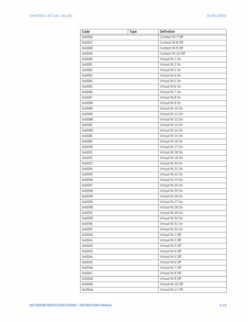
CHAPTER 4: ACTUAL VALUES A3 RECORDS
350 FEEDER PROTECTION SYSTEM – INSTRUCTION MANUAL 4–13
0x0066 Contact IN 7 Off
0x0067 Contact IN 8 Off
0x0068 Contact IN 9 Off
0x0069 Contact IN 10 Off
0x0080 Virtual IN 1 On
0x0081 Virtual IN 2 On
0x0082 Virtual IN 3 On
0x0083 Virtual IN 4 On
0x0084 Virtual IN 5 On
0x0085 Virtual IN 6 On
0x0086 Virtual IN 7 On
0x0087 Virtual IN 8 On
0x0088 Virtual IN 9 On
0x0089 Virtual IN 10 On
0x008A Virtual IN 11 On
0x008B Virtual IN 12 On
0x008C Virtual IN 13 On
0x008D Virtual IN 14 On
0x008E Virtual IN 15 On
0x008F Virtual IN 16 On
0x0090 Virtual IN 17 On
0x0091 Virtual IN 18 On
0x0092 Virtual IN 19 On
0x0093 Virtual IN 20 On
0x0094 Virtual IN 21 On
0x0095 Virtual IN 22 On
0x0096 Virtual IN 23 On
0x0097 Virtual IN 24 On
0x0098 Virtual IN 25 On
0x0099 Virtual IN 26 On
0x009A Virtual IN 27 On
0x009B Virtual IN 28 On
0x009C Virtual IN 29 On
0x009D Virtual IN 30 On
0x009E Virtual IN 31 On
0x009F Virtual IN 32 On
0x00A0 Virtual IN 1 Off
0x00A1 Virtual IN 2 Off
0x00A2 Virtual IN 3 Off
0x00A3 Virtual IN 4 Off
0x00A4 Virtual IN 5 Off
0x00A5 Virtual IN 6 Off
0x00A6 Virtual IN 7 Off
0x00A7 Virtual IN 8 Off
0x00A8 Virtual IN 9 Off
0x00A9 Virtual IN 10 Off
0x00AA Virtual IN 11 Off
Code Type Definition

4–14 350 FEEDER PROTECTION SYSTEM – INSTRUCTION MANUAL
A3 RECORDS CHAPTER 4: ACTUAL VALUES
0x00AB Virtual IN 12 Off
0x00AC Virtual IN 13 Off
0x00AD Virtual IN 14 Off
0x00AE Virtual IN 15 Off
0x00AF Virtual IN 16 Off
0x00B0 Virtual IN 17 Off
0x00B1 Virtual IN 18 Off
0x00B2 Virtual IN 19 Off
0x00B3 Virtual IN 20 Off
0x00B4 Virtual IN 21 Off
0x00B5 Virtual IN 22 Off
0x00B6 Virtual IN 23 Off
0x00B7 Virtual IN 24 Off
0x00B8 Virtual IN 25 Off
0x00B9 Virtual IN 26 Off
0x00BA Virtual IN 27 Off
0x00BB Virtual IN 28 Off
0x00BC Virtual IN 29 Off
0x00BD Virtual IN 30 Off
0x00BE Virtual IN 31 Off
0x00BF Virtual IN 32 Off
0x01C0 Remote IN 1 On
0x01C1 Remote IN 2 On
0x01C2 Remote IN 3 On
0x01C3 Remote IN 4 On
0x01C4 Remote IN 5 On
0x01C5 Remote IN 6 On
0x01C6 Remote IN 7 On
0x01C7 Remote IN 8 On
0x01C8 Remote IN 9 On
0x01C9 Remote IN 10 On
0x01CA Remote IN 11 On
0x01CB Remote IN 12 On
0x01CC Remote IN 13 On
0x01CD Remote IN 14 On
0x01CE Remote IN 15 On
0x01CF Remote IN 16 On
0x01D0 Remote IN 17 On
0x01D1 Remote IN 18 On
0x01D2 Remote IN 19 On
0x01D3 Remote IN 20 On
0x01D4 Remote IN 21 On
0x01D5 Remote IN 22 On
0x01D6 Remote IN 23 On
0x01D7 Remote IN 24 On
0x01D8 Remote IN 25 On
0x01D9 Remote IN 26 On
Code Type Definition

CHAPTER 4: ACTUAL VALUES A3 RECORDS
350 FEEDER PROTECTION SYSTEM – INSTRUCTION MANUAL 4–15
0x01DA Remote IN 27 On
0x01DB Remote IN 28 On
0x01DC Remote IN 29 On
0x01DD Remote IN 30 On
0x01DE Remote IN 31 On
0x01DF Remote IN 32 On
0x01E0 Remote IN 1 Off
0x01E1 Remote IN 2 Off
0x01E2 Remote IN 3 Off
0x01E3 Remote IN 4 Off
0x01E4 Remote IN 5 Off
0x01E5 Remote IN 6 Off
0x01E6 Remote IN 7 Off
0x01E7 Remote IN 8 Off
0x01E8 Remote IN 9 Off
0x01E9 Remote IN 10 Off
0x01EA Remote IN 11 Off
0x01EB Remote IN 12 Off
0x01EC Remote IN 13 Off
0x01ED Remote IN 14 Off
0x01EE Remote IN 15 Off
0x01EF Remote IN 16 Off
0x01F0 Remote IN 17 Off
0x01F1 Remote IN 18 Off
0x01F2 Remote IN 19 Off
0x01F3 Remote IN 20 Off
0x01F4 Remote IN 21 Off
0x01F5 Remote IN 22 Off
0x01F6 Remote IN 23 Off
0x01F7 Remote IN 24 Off
0x01F8 Remote IN 25 Off
0x01F9 Remote IN 26 Off
0x01FA Remote IN 27 Off
0x01FB Remote IN 28 Off
0x01FC Remote IN 29 Off
0x01FD Remote IN 30 Off
0x01FE Remote IN 31 Off
0x01FF Remote IN 32 Off
0x8041 Therm O/L Trip PKP
0x8042 Therm O/L Trip OP
0x8044 Therm O/L Trip DPO
0x8049 Therm PhA Trip PKP
0x804A Therm PhA Trip OP
0x804C Therm PhA Trip DPO
0x8051 Therm PhB Trip PKP
0x8052 Therm PhB Trip OP
0x8054 Therm PhB Trip DPO
Code Type Definition

4–16 350 FEEDER PROTECTION SYSTEM – INSTRUCTION MANUAL
A3 RECORDS CHAPTER 4: ACTUAL VALUES
0x8061 Therm PhC Trip PKP
0x8062 Therm PhC Trip OP
0x8064 Therm PhC Trip DPO
0x84C1 LE 1 Trip PKP
0x84C2 LE 1 Trip OP
0x84C4 LE 1 Trip DPO
0x8501 LE 2 Trip PKP
0x8502 LE 2 Trip OP
0x8504 LE 2 Trip DPO
0x8541 LE 3 Trip PKP
0x8542 LE 3 Trip OP
0x8544 LE 3 Trip DPO
0x8581 LE 4 Trip PKP
0x8582 LE 4 Trip OP
0x8584 LE 4 Trip DPO
0x85C1 LE 5 Trip PKP
0x85C2 LE 5 Trip OP
0x85C4 LE 5 Trip DPO
0x8601 LE 6 Trip PKP
0x8602 LE 6 Trip OP
0x8604 LE 6 Trip DPO
0x8641 LE 7 Trip PKP
0x8642 LE 7 Trip OP
0x8644 LE 7 Trip DPO
0x8681 LE 8 Trip PKP
0x8682 LE 8 Trip OP
0x8684 LE 8 Trip DPO
0x89C2 Self Test OP
0x9001 Ph IOC1 Trip PKP
0x9002 Ph IOC1 Trip OP
0x9004 Ph IOC1 Trip DPO
0x9009 Ph A IOC1 Trip PKP
0x900A Ph A IOC1 Trip OP
0x900C Ph A IOC1 Trip DPO
0x9011 Ph B IOC1 Trip PKP
0x9012 Ph B IOC1 Trip OP
0x9014 Ph B IOC1 Trip DPO
0x9021 Ph C IOC1 Trip PKP
0x9022 Ph C IOC1 Trip OP
0x9024 Ph C IOC1 Trip DPO
0x9041 Ntrl IOC1 Trip PKP
0x9042 Ntrl IOC1 Trip OP
0x9044 Ntrl IOC1 Trip DPO
0x9081 Gnd IOC1 Trip PKP
0x9082 Gnd IOC1 Trip OP
0x9084 Gnd IOC1 Trip DPO
0x90C1 Ph TOC1 Trip PKP
Code Type Definition

CHAPTER 4: ACTUAL VALUES A3 RECORDS
350 FEEDER PROTECTION SYSTEM – INSTRUCTION MANUAL 4–17
0x90C2 Ph TOC1 Trip OP
0x90C4 Ph TOC1 Trip DPO
0x90C9 Ph A TOC1 Trip PKP
0x90CA Ph A TOC1 Trip OP
0x90CC Ph A TOC1 Trip DPO
0x90D1 Ph B TOC1 Trip PKP
0x90D2 Ph B TOC1 Trip OP
0x90D4 Ph B TOC1 Trip DPO
0x90E1 Ph C TOC1 Trip PKP
0x90E2 Ph C TOC1 Trip OP
0x90E4 Ph C TOC1 Trip DPO
0x9101 Ntrl TOC1 Trip PKP
0x9102 Ntrl TOC1 Trip OP
0x9104 Ntrl TOC1 Trip DPO
0x9141 Gnd TOC1 Trip PKP
0x9142 Gnd TOC1 Trip OP
0x9144 Gnd TOC1 Trip DPO
0x9181 Ph IOC2 Trip PKP
0x9182 Ph IOC2 Trip OP
0x9184 Ph IOC2 Trip DPO
0x9189 Ph A IOC2 Trip PKP
0x918A Ph A IOC2 Trip OP
0x918C Ph A IOC2 Trip DPO
0x9191 Ph B IOC2 Trip PKP
0x9192 Ph B IOC2 Trip OP
0x9194 Ph B IOC2 Trip DPO
0x91A1 Ph C IOC2 Trip PKP
0x91A2 Ph C IOC2 Trip OP
0x91A4 Ph C IOC2 Trip DPO
0x91C1 Ntrl IOC2 Trip PKP
0x91C2 Ntrl IOC2 Trip OP
0x91C4 Ntrl IOC2 Trip DPO
0x9201 Gnd IOC2 Trip PKP
0x9202 Gnd IOC2 Trip OP
0x9204 Gnd IOC2 Trip DPO
0x9301 SGnd TOC1 Trip PKP
0x9302 SGnd TOC1 Trip OP
0x9304 SGnd TOC1 Trip DPO
0x93C1 NegSeq OV Trp PKP
0x93C2 NegSeq OV Trp OP
0x93C4 NegSeq OV Trp DPO
0x9401 Ntrl OV Trip PKP
0x9402 Ntrl OV Trp OP
0x9404 Ntrl OV Trip DPO
0x9441 Ph OV1 Trip PKP
0x9442 Ph OV1 Trip OP
0x9444 Ph OV1 Trip DPO
Code Type Definition

4–18 350 FEEDER PROTECTION SYSTEM – INSTRUCTION MANUAL
A3 RECORDS CHAPTER 4: ACTUAL VALUES
0x9449 Ph A OV1 Trip PKP
0x944A Ph A OV1 Trip OP
0x944C Ph A OV1 Trip DPO
0x9451 Ph B OV1 Trip PKP
0x9452 Ph B OV1 Trip OP
0x9454 Ph B OV1 Trip DPO
0x9461 Ph C OV1 Trip PKP
0x9462 Ph C OV1 Trip OP
0x9464 Ph C OV1 Trip DPO
0x9481 Ph UV1 Trip PKP
0x9482 Ph UV1 Trip OP
0x9484 Ph UV1 Trip DPO
0x9489 Ph A UV1 Trip PKP
0x948A Ph A UV1 Trip OP
0x948C Ph A UV1 Trip DPO
0x9491 Ph B UV1 Trip PKP
0x9492 Ph B UV1 Trip OP
0x9494 Ph B UV1 Trip DPO
0x94A1 Ph C UV1 Trip PKP
0x94A2 Ph C UV1 Trip OP
0x94A4 Ph C UV1 Trip DPO
0x94C1 Aux OV Trip PKP
0x94C2 Aux OV Trip OP
0x94C4 Aux OV Trip DPO
0x9501 Aux UV Trip PKP
0x9502 Aux UV Trip Op
0x9504 Aux UV Trip DPO
0x9541 UndrFreq1 Trip PKP
0x9542 UndrFreq1 Trip OP
0x9544 UndrFreq1 Trip DPO
0x9581 UndrFreq2 Trip PKP
0x9582 UndrFreq2 Trip OP
0x9584 UndrFreq2 Trip DPO
0x95C1 OverFreq1 Trip PKP
0x95C2 OverFreq1 Trip OP
0x95C4 OverFreq1 Trip DPO
0x9601 OverFreq2 Trip PKP
0x9602 OverFreq2 Trip OP
0x9604 OverFreq2 Trip DPO
0x9641 SGnd IOC1 Trip PKP
0x9642 SGnd IOC1 Trip OP
0x9644 SGnd IOC1 Trip DPO
0x9681 SGnd IOC2 Trip PKP
0x9682 SGnd IOC2 Trip OP
0x9684 SGnd IOC2 Trip DPO
0x96C1 NegSeq IOC Trp PKP
0x96C2 NegSeq IOC Trp OP
Code Type Definition

CHAPTER 4: ACTUAL VALUES A3 RECORDS
350 FEEDER PROTECTION SYSTEM – INSTRUCTION MANUAL 4–19
0x96C4 NegSeq IOC Trp DPO
0x9C01 LE 9 Trip PKP
0x9C02 LE 9 Trip OP
0x9C04 LE 9 Trip DPO
0x9C41 LE 10 Trip PKP
0x9C42 LE 10 Trip OP
0x9C44 LE 10 Trip DPO
0x9C81 LE 11 Trip PKP
0x9C82 LE 11 Trip OP
0x9C84 LE 11 Trip DPO
0x9CC1 LE 12 Trip PKP
0x9CC2 LE 12 Trip OP
0x9CC4 LE 12 Trip DPO
0x9D01 LE 13 Trip PKP
0x9D02 LE 13 Trip OP
0x9D04 LE 13 Trip DPO
0x9D41 LE 14 Trip PKP
0x9D42 LE 14 Trip OP
0x9D44 LE 14 Trip DPO
0x9D81 LE 15 Trip PKP
0x9D82 LE 15 Trip OP
0x9D84 LE 15 Trip DPO
0x9DC1 LE 16 Trip PKP
0x9DC2 LE 16 Trip OP
0x9DC4 LE 16 Trip DPO
0xA049 Therm PhA Alrm PKP
0xA04A Therm PhA Alrm OP
0xA04C Therm PhA Alrm DPO
0xA051 Therm PhB Alrm PKP
0xA052 Therm PhB Alrm OP
0xA054 Therm PhB Alrm DPO
0xA061 Therm PhC Alrm PKP
0xA062 Therm PhC Alrm OP
0xA064 Therm PhC Alrm DPO
0xA482 Relay Not Ready
0xA4C1 LE 1 Alarm PKP
0xA4C2 LE 1 Alarm OP
0xA4C4 LE 1 Alarm DPO
0xA501 LE 2 Alarm PKP
0xA502 LE 2 Alarm OP
0xA504 LE 2 Alarm DPO
0xA541 LE 3 Alarm PKP
0xA542 LE 3 Alarm OP
0xA544 LE 3 Alarm DPO
0xA581 LE 4 Alarm PKP
0xA582 LE 4 Alarm OP
0xA584 LE 4 Alarm DPO
Code Type Definition

4–20 350 FEEDER PROTECTION SYSTEM – INSTRUCTION MANUAL
A3 RECORDS CHAPTER 4: ACTUAL VALUES
0xA5C1 LE 5 Alarm PKP
0xA5C2 LE 5 Alarm OP
0xA5C4 LE 5 Alarm DPO
0xA601 LE 6 Alarm PKP
0xA602 LE 6 Alarm OP
0xA604 LE 6 Alarm DPO
0xA641 LE 7 Alarm PKP
0xA642 LE 7 Alarm OP
0xA644 LE 7 Alarm DPO
0xA681 LE 8 Alarm PKP
0xA682 LE 8 Alarm OP
0xA684 LE 8 Alarm DPO
0xABC1 HI Amb Temp PKP
0xABC2 HI Amb Temp OP
0xABC4 HI Amb Temp DPO
0xAC01 LO Amb Temp PKP
0xAC02 LO Amb Temp OP
0xAC04 LO Amb Temp DPO
0xAC42 Self Test Alarm OP
0xACC2 BKRTrpCntrAlrm OP
0xAD02 R1 CoilMonAlrm OP
0xAD42 R2 CoilMonAlrm OP
0xAD81 BKR1 Fail Alrm PKP
0xAD82 BKR1 Fail Alrm OP
0xAD84 BKR1 Fail Alrm DPO
0xADC2 BKR1 Stat Fail OP
0xAE41 CLP Alarm PKP
0xAE42 CLP Alarm OP
0xAE44 CLP Alarm DPO
0xB001 Ph IOC1 Alarm PKP
0xB002 Ph IOC1 Alarm OP
0xB004 Ph IOC1 Alarm DPO
0xB009 Ph A IOC1 Alrm PKP
0xB00A Ph A IOC1 Alrm OP
0xB00C Ph A IOC1 Alrm DPO
0xB011 Ph B IOC1 Alrm PKP
0xB012 Ph B IOC1 Alrm OP
0xB014 Ph B IOC1 Alrm DPO
0xB021 Ph C IOC1 Alrm PKP
0xB022 Ph C IOC1 Alrm OP
0xB024 Ph C IOC1 Alrm DPO
0xB041 Ntrl IOC1 Alrm PKP
0xB042 Ntrl IOC1 Alrm OP
0xB044 Ntrl IOC1 Alrm DPO
0xB081 Gnd IOC1 Alarm PKP
0xB082 Gnd IOC1 Alarm OP
0xB084 Gnd IOC1 Alarm DPO
Code Type Definition

CHAPTER 4: ACTUAL VALUES A3 RECORDS
350 FEEDER PROTECTION SYSTEM – INSTRUCTION MANUAL 4–21
0xB0C1 Ph TOC1 Alarm PKP
0xB0C2 Ph TOC1 Alarm OP
0xB0C4 Ph TOC1 Alarm DPO
0xB0C9 Ph A TOC1 Alrm PKP
0xB0CA Ph A TOC1 Alrm OP
0xB0CC Ph A TOC1 Alrm DPO
0xB0D1 Ph B TOC1 Alrm PKP
0xB0D2 Ph B TOC1 Alrm OP
0xB0D4 Ph B TOC1 Alrm DPO
0xB0E1 Ph C TOC1 Alrm PKP
0xB0E2 Ph C TOC1 Alrm OP
0xB0E4 Ph C TOC1 Alrm DPO
0xB101 Ntrl TOC1 Alrm PKP
0xB102 Ntrl TOC1 Alrm OP
0xB104 Ntrl TOC1 Alrm DPO
0xB141 Gnd TOC1 Alarm PKP
0xB142 Gnd TOC1 Alarm OP
0xB144 Gnd TOC1 Alarm DPO
0xB181 Ph IOC2 Alarm PKP
0xB182 Ph IOC2 Alarm OP
0xB184 Ph IOC2 Alarm DPO
0xB189 Ph A IOC2 Alrm PKP
0xB18A Ph A IOC2 Alrm OP
0xB18C Ph A IOC2 Alrm DPO
0xB191 Ph B IOC2 Alrm PKP
0xB192 Ph B IOC2 Alrm OP
0xB194 Ph B IOC2 Alrm DPO
0xB1A1 Ph C IOC2 Alrm PKP
0xB1A2 Ph C IOC2 Alrm OP
0xB1A4 Ph C IOC2 Alrm DPO
0xB1C1 Ntrl IOC2 Alrm PKP
0xB1C2 Ntrl IOC2 Alrm OP
0xB1C4 Ntrl IOC2 Alrm DPO
0xB201 Gnd IOC2 Alarm PKP
0xB202 Gnd IOC2 Alarm OP
0xB204 Gnd IOC2 Alarm DPO
0xB301 SGnd TOC1 Alrm PKP
0xB302 SGnd TOC1 Alrm OP
0xB304 SGnd TOC1 Alrm DPO
0xB342 NtrlDir RevAlm OP
0xB344 NtrlDir RevAlm DPO
0xB382 GndDir RevAlm OP
0xB384 GndDir RevAlm DPO
0xB3C1 NegSeq OV Alrm PKP
0xB3C2 NegSeq OV Alrm OP
0xB3C4 NegSeq OV Alrm DPO
0xB401 Ntrl OV Alrm PKP
Code Type Definition

4–22 350 FEEDER PROTECTION SYSTEM – INSTRUCTION MANUAL
A3 RECORDS CHAPTER 4: ACTUAL VALUES
0xB402 Ntrl OV Alrm OP
0xB404 Ntrl OV Alrm DPO
0xB441 Ph OV1 Alarm PKP
0xB442 Ph OV1 Alarm OP
0xB444 Ph OV1 Alarm DPO
0xB449 Ph A OV1 Alarm PKP
0xB44A Ph A OV1 Alarm OP
0xB44C Ph A OV1 Alarm DPO
0xB451 Ph B OV1 Alarm PKP
0xB452 Ph B OV1 Alarm OP
0xB454 Ph B OV1 Alarm DPO
0xB461 Ph C OV1 Alarm PKP
0xB462 Ph C OV1 Alarm OP
0xB464 Ph C OV1 Alarm DPO
0xB481 Ph UV1 Alarm PKP
0xB482 Ph UV1 Alarm OP
0xB484 Ph UV1 Alarm DPO
0xB489 Ph A UV1 Alarm PKP
0xB48A Ph A UV1 Alarm OP
0xB48C Ph A UV1 Alarm DPO
0xB491 Ph B UV1 Alarm PKP
0xB492 Ph B UV1 Alarm OP
0xB494 Ph B UV1 Alarm DPO
0xB4A1 Ph C UV1 Alarm PKP
0xB4A2 Ph C UV1 Alarm OP
0xB4A4 Ph C UV1 Alarm DPO
0xB4C1 Aux OV Alarm PKP
0xB4C2 Aux OV Alarm OP
0xB4C4 Aux OV Alarm DPO
0xB501 Aux UV Alarm PKP
0xB502 Aux UV Alarm OP
0xB504 Aux UV Alarm DPO
0xB541 UndrFreq1 Alrm PKP
0xB542 UndrFreq1 Alrm OP
0xB544 UndrFreq1 Alrm DPO
0xB581 UndrFreq2 Alrm PKP
0xB582 UndrFreq2 Alrm OP
0xB584 UndrFreq2 Alrm DPO
0xB5C1 OverFreq1 Alrm PKP
0xB5C2 OverFreq1 Alrm OP
0xB5C4 OverFreq1 Alrm DPO
0xB601 OverFreq2 Alrm PKP
0xB602 OverFreq2 Alrm OP
0xB604 OverFreq2 Alrm DPO
0xB641 SGnd IOC1 Alrm PKP
0xB642 SGnd IOC1 Alrm OP
0xB644 SGnd IOC1 Alrm DPO
Code Type Definition

CHAPTER 4: ACTUAL VALUES A3 RECORDS
350 FEEDER PROTECTION SYSTEM – INSTRUCTION MANUAL 4–23
0xB681 SGnd IOC2 Alrm PKP
0xB682 SGnd IOC2 Alrm OP
0xB684 SGnd IOC2 Alrm DPO
0xB6C1 NSeq IOC Alrm PKP
0xB6C2 NSeq IOC Alrm OP
0xB6C4 NSeq IOC Alrm DPO
0xB889 Ph A OV2 Alarm PKP
0xBC01 LE 9 Alarm PKP
0xBC02 LE 9 Alarm OP
0xBC04 LE 9 Alarm DPO
0xBC41 LE 10 Alarm PKP
0xBC42 LE 10 Alarm OP
0xBC44 LE 10 Alarm DPO
0xBC81 LE 11 Alarm PKP
0xBC82 LE 11 Alarm OP
0xBC84 LE 11 Alarm DPO
0xBCC1 LE 12 Alarm PKP
0xBCC2 LE 12 Alarm OP
0xBCC4 LE 12 Alarm DPO
0xBD01 LE 13 Alarm PKP
0xBD02 LE 13 Alarm OP
0xBD04 LE 13 Alarm DPO
0xBD41 LE 14 Alarm PKP
0xBD42 LE 14 Alarm OP
0xBD44 LE 14 Alarm DPO
0xBD81 LE 15 Alarm PKP
0xBD82 LE 15 Alarm OP
0xBD84 LE 15 Alarm DPO
0xBDC1 LE 16 Alarm PKP
0xBDC2 LE 16 Alarm OP
0xBDC4 LE 16 Alarm DPO
0xC042 Output Relay 3 On
0xC082 Output Relay 4 On
0xC0C2 Output Relay 5 On
0xC102 Output Relay 6 On
0xC142 Self-Test Rly 7 On
0xC182 Output Relay 1 On
0xC184 Output Relay 1 Off
0xC1C2 Output Relay 2 On
0xC1C4 Output Relay 2 Off
0xC202 BKR Connected
0xC4C1 LE 1 PKP
0xC4C2 LE 1 OP
0xC4C4 LE 1 DPO
0xC501 LE 2 PKP
0xC502 LE 2 OP
0xC504 LE 2 DPO
Code Type Definition

4–24 350 FEEDER PROTECTION SYSTEM – INSTRUCTION MANUAL
A3 RECORDS CHAPTER 4: ACTUAL VALUES
0xC541 LE 3 PKP
0xC542 LE 3 OP
0xC544 LE 3 DPO
0xC581 LE 4 PKP
0xC582 LE 4 OP
0xC584 LE 4 DPO
0xC5C1 LE 5 PKP
0xC5C2 LE 5 OP
0xC5C4 LE 5 DPO
0xC601 LE 6 PKP
0xC602 LE 6 OP
0xC604 LE 6 DPO
0xC641 LE 7 PKP
0xC642 LE 7 OP
0xC644 LE 7 DPO
0xC681 LE 8 PKP
0xC682 LE 8 OP
0xC684 LE 8 DPO
0xC882 Setpoint Group2 On
0xC902 Open Breaker
0xC942 Close Breaker
0xC982 Maint. Req. OP
0xCA02 52a Contact OP
0xCA42 52b Contact OP
0xCA44 52b Contact DPO
0xCA82 Reset OK
0xCB01 AR Close PKP
0xCB02 AR Close
0xCB04 AR Close DPO
0xCB42 AR N/Ready
0xCB44 AR N/Ready DPO
0xCB82 AR In Progress
0xCBC2 AR Disabled
0xCC02 AR Ext. Init
0xCC42 AR Ready
0xCCC2 BKR Stat Open
0xCD02 BKR Stat Clsd
0xCD42 Setpoint Group1 On
0xCE41 CLP PKP
0xCE42 CLP Op
0xCE44 CLP DPO
0xD041 Ntrl IOC1 PKP
0xD042 Ntrl IOC1 OP
0xD044 Ntrl IOC1 DPO
0xD081 Gnd IOC1 PKP
0xD082 Gnd IOC1 OP
0xD084 Gnd IOC1 DPO
Code Type Definition

CHAPTER 4: ACTUAL VALUES A3 RECORDS
350 FEEDER PROTECTION SYSTEM – INSTRUCTION MANUAL 4–25
0xD0C1 Ph TOC1 PKP
0xD0C2 Ph TOC1 OP
0xD0C4 Ph TOC1 DPO
0xD101 Ntrl TOC1 PKP
0xD102 Ntrl TOC1 OP
0xD104 Ntrl TOC1 DPO
0xD141 Gnd TOC1 PKP
0xD142 Gnd TOC1 OP
0xD144 Gnd TOC1 DPO
0xD181 Ph IOC2 PKP
0xD184 Ph IOC2 DPO
0xD1C1 Ntrl IOC2 PKP
0xD1C2 Ntrl IOC2 OP
0xD1C4 Ntrl IOC2 DPO
0xD201 Gnd IOC2 PKP
0xD202 Gnd IOC2 OP
0xD204 Gnd IOC2 DPO
0xD342 Ntrl Dir Rev OP
0xD344 Ntrl Dir Rev DPO
0xD382 Gnd Dir Rev OP
0xD384 Gnd Dir Rev DPO
0xD3C1 NegSeq OV PKP
0xD3C2 NegSeq OV OP
0xD3C4 NegSeq OV DPO
0xD401 Ntrl OV PKP
0xD402 Ntrl OV OP
0xD404 Ntrl OV DPO
0xD441 Ph OV1 PKP
0xD442 Ph OV1 OP
0xD444 Ph OV1 DPO
0xD481 Ph UV1 PKP
0xD482 Ph UV1 OP
0xD484 Ph UV1 DPO
0xDC01 LE 9 PKP
0xDC02 LE 9 OP
0xDC04 LE 9 DPO
0xDC41 LE 10 PKP
0xDC42 LE 10 OP
0xDC44 LE 10 DPO
0xDC81 LE 11 PKP
0xDC82 LE 11 OP
0xDC84 LE 11 DPO
0xDCC1 LE 12 PKP
0xDCC2 LE 12 OP
0xDCC4 LE 12 DPO
0xDD01 LE 13 PKP
0xDD02 LE 13 OP
Code Type Definition

4–26 350 FEEDER PROTECTION SYSTEM – INSTRUCTION MANUAL
A3 RECORDS CHAPTER 4: ACTUAL VALUES
0xDD04 LE 13 DPO
0xDD41 LE 14 PKP
0xDD42 LE 14 OP
0xDD44 LE 14 DPO
0xDD81 LE 15 PKP
0xDD82 LE 15 OP
0xDD84 LE 15 DPO
0xDDC1 LE 16 PKP
0xDDC2 LE 16 OP
0xDDC4 LE 16 DPO
0xE042 Therm O/L Blck OP
0xE044 Therm O/L Blck Off
0xE182 Output Relay 1 BLK
0xE184 Relay 1 BLK Off
0xE1C2 Output Relay 2 BLK
0xE1C4 Relay 2 BLK Off
0xE882 Group Change Blk
0xE884 Grp Change Blk DPO
0xEB02 AR Block
0xEB04 AR Block DPO
0xEE82 CLP Ph IOC1 BLK
0xEE84 CLP Ph IOC1 BLKDPO
0xEEC2 CLP Ph IOC2 BLK
0xEEC4 CLP Ph IOC2 BLKDPO
0xEF02 CLPNtrlIOC1 BLK
0xEF04 CLPNtrlIOC1 BLKDPO
0xEF42 CLPNtrlIOC2 BLK
0xEF44 CLPNtrlIOC2 BLKDPO
0xEF82 CLP GndIOC1 BLK
0xEF84 CLP GndIOC1 BLKDPO
0xEFC2 CLP GndIOC2 BLK
0xEFC4 CLP GndIOC2 BLKDPO
0xF002 Ph IOC1 Block
0xF004 Ph IOC1 Block DPO
0xF042 Ntrl IOC1 Block
0xF044 Ntrl IOC1 Blk DPO
0xF082 Gnd IOC1 Block
0xF084 Gnd IOC1 Block DPO
0xF0C2 Ph TOC1 Block
0xF0C4 Ph TOC1 Block DPO
0xF102 Ntrl TOC1 Block
0xF104 Ntrl TOC1 BlockDPO
0xF142 Gnd TOC1 Block
0xF144 Gnd TOC1 Block DPO
0xF182 Ph IOC2 Block
0xF184 Ph IOC2 Block DPO
0xF1C2 Ntrl IOC2 Block
Code Type Definition

CHAPTER 4: ACTUAL VALUES A3 RECORDS
350 FEEDER PROTECTION SYSTEM – INSTRUCTION MANUAL 4–27
0xF1C4 Ntrl IOC2 Blk DPO
0xF202 Gnd IOC2 Block
0xF204 Gnd IOC2 Block DPO
0xF302 SGnd TOC1 Block
0xF304 SGnd TOC1 BlockDPO
0xF342 Ntrl Dir Block
0xF344 Ntrl Dir Block DPO
0xF382 Gnd Dir Block
0xF384 Gnd Dir Block DPO
0xF3C2 NegSeq OV Block
0xF3C4 NSeq OV Blk DPO
0xF402 Ntrl OV Block
0xF404 Ntrl OV Block DPO
0xF442 Ph OV1 Block
0xF444 Ph OV1 Block DPO
0xF482 Ph UV1 Block
0xF484 Ph UV1 Block DPO
0xF4C2 Aux OV Block
0xF4C4 Aux OV Block DPO
0xF502 Aux UV Block
0xF504 Aux UV Block DPO
0xF542 UndrFreq1 Block
0xF544 UndrFreq1 BlockDPO
0xF582 UndrFreq2 Block
0xF584 UndrFreq2 BlockDPO
0xF5C2 OverFreq1 Block
0xF5C4 OverFreq1 Blk DPO
0xF602 OverFreq2 Block
0xF604 OverFreq2 BlockDPO
0xF642 SGnd IOC1 Block
0xF644 SGnd IOC1 Blk DPO
0xF682 SGnd IOC2 Block
0xF684 SGnd IOC2 Blk DPO
0xF6C2 NSeq IOC Block
0xF6C4 NSeq IOC Block DPO
Code Type Definition

4–28 350 FEEDER PROTECTION SYSTEM – INSTRUCTION MANUAL
A3 RECORDS CHAPTER 4: ACTUAL VALUES
Transient recordsPATH: ACTUAL VALUES > A3 RECORDS > TRANSIENT RECORDS
FORCE TRIGGER?
NoRange: No, Yes
TOTAL RECORDS
1
Range: N/A
AVAILABLE RECORDS
1
Range: N/A
LAST CLEARED
Feb 08 2009
Range: N/A
Clear event recordPATH: ACTUAL VALUES > A3 RECORDS > CLEAR EVENT REC
CLEAR
No
Range: No, Yes
When set to "Yes," pressing the ENTER key will clear all event records.
Clear transient recordPATH: ACTUAL VALUES > A3 RECORDS > CLEAR TRANST REC
CLEAR
No
Range: No, Yes
When set to "Yes," pressing the ENTER key will clear all transient records.
Clear thermal capacity recordPATH: ACTUAL VALUES > A3 RECORDS > CLEAR THERM CAP
CLEAR
No
Range: No, Yes
When set to "Yes," pressing the ENTER key will clear all thermal capacity records.
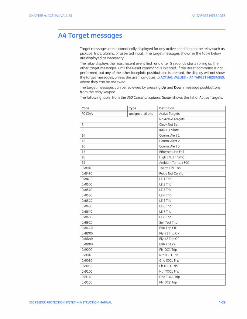
CHAPTER 4: ACTUAL VALUES A4 TARGET MESSAGES
350 FEEDER PROTECTION SYSTEM – INSTRUCTION MANUAL 4–29
A4 Target messages
Target messages are automatically displayed for any active condition on the relay such as pickups, trips, alarms, or asserted input. The target messages shown in the table below are displayed as necessary. The relay displays the most recent event first, and after 5 seconds starts rolling up the other target messages, until the Reset command is initiated. If the Reset command is not performed, but any of the other faceplate pushbuttons is pressed, the display will not show the target messages, unless the user navigates to ACTUAL VALUES > A4 TARGET MESSAGES, where they can be reviewed. The target messages can be reviewed by pressing Up and Down message pushbuttons from the relay keypad.The following table, from the 350 Communications Guide, shows the list of Active Targets.
Code Type Definition
FC134A unsigned 16 bits Active Targets
0 No Active Targets
7 Clock Not Set
8 IRIG-B Failure
14 Comm. Alert 1
15 Comm. Alert 2
16 Comm. Alert 3
17 Ethernet Link Fail
18 High ENET Traffic
19 Ambient Temp. >80C
0x8040 Therm O/L Trip
0x8480 Relay Not Config
0x84C0 LE 1 Trip
0x8500 LE 2 Trip
0x8540 LE 3 Trip
0x8580 LE 4 Trip
0x85C0 LE 5 Trip
0x8600 LE 6 Trip
0x8640 LE 7 Trip
0x8680 LE 8 Trip
0x89C0 Self Test Trip
0x8CC0 BKR Trip Ctr
0x8D00 Rly #1 Trip OP
0x8D40 Rly #2 Trip OP
0x8D80 BKR Failure
0x9000 Ph IOC1 Trip
0x9040 Ntrl IOC1 Trip
0x9080 Gnd IOC1 Trip
0x90C0 Ph TOC1 Trip
0x9100 Ntrl TOC1 Trip
0x9140 Gnd TOC1 Trip
0x9180 Ph IOC2 Trip

4–30 350 FEEDER PROTECTION SYSTEM – INSTRUCTION MANUAL
A4 TARGET MESSAGES CHAPTER 4: ACTUAL VALUES
0x91C0 Ntrl IOC2 Trip
0x9200 Gnd IOC2 Trip
0x9240 Ph TOC2 Trip
0x9280 Ntrl TOC2 Trip
0x92C0 Gnd TOC2 Trip
0x9300 SGnd TOC1 Trip
0x93C0 NegSeq OV Trip
0x9400 Ntrl OV Trip
0x9440 Ph OV1 Trip
0x9480 Ph UV1 Trip
0x94C0 Aux OV Trip
0x9500 Aux UV Trip
0x9540 UndrFreq1 Trip
0x9580 UndrFreq2 Trip
0x95C0 OverFreq1 Trip
0x9600 OverFreq2 Trip
0x9640 SGnd IOC1 Trip
0x9680 SGnd IOC2 Trip
0x96C0 NegSeq IOC Trip
0x9800 NSeq TOC1 Trip
0x9840 NSeq TOC2 Trip
0x99C0 SGnd TOC2 Trip
0x9C00 LE 9 Trip
0x9C40 LE 10 Trip
0x9C80 LE 11 Trip
0x9CC0 LE 12 Trip
0x9D00 LE 13 Trip
0x9D40 LE 14 Trip
0x9D80 LE 15 Trip
0x9DC0 LE 16 Trip
0xA040 Therm Lvl Alrm
0xA480 Not Configured
0xA4C0 LE 1 Alarm
0xA500 LE 2 Alarm
0xA540 LE 3 Alarm
0xA580 LE 4 Alarm
0xA5C0 LE 5 Alarm
0xA600 LE 6 Alarm
0xA640 LE 7 Alarm
0xA680 LE 8 Alarm
0xABC0 HI Ambient Temp
0xAC00 LO Ambient Temp
0xAC40 Self Test Alarm
0xACC0 BKRTrpCntrAlrm
0xAD00 Rly1 Coil Mn Alrm
0xAD40 Rly2 Coil Mn Alrm
0xAD80 BKR Fail Alrm
Code Type Definition

CHAPTER 4: ACTUAL VALUES A4 TARGET MESSAGES
350 FEEDER PROTECTION SYSTEM – INSTRUCTION MANUAL 4–31
0xADC0 BKRStatus Fail
0xAE40 CLP Alarm
0xB000 Ph IOC1 Alarm
0xB040 Ntrl IOC1 Alarm
0xB080 Gnd IOC1 Alarm
0xB0C0 Ph TOC1 Alarm
0xB100 Ntrl TOC1 Alrm
0xB140 Gnd TOC1 Alarm
0xB180 Ph IOC2 Alarm
0xB1C0 Ntrl IOC2 Alarm
0xB200 Gnd IOC2 Alarm
0xB240 Ph TOC2 Alarm
0xB280 Ntrl TOC2 Alrm
0xB2C0 Gnd TOC2 Alarm
0xB300 SGnd TOC1 Alarm
0xB340 Ntrl Dir Alrm
0xB3C0 NegSeq OV Alarm
0xB400 Ntrl OV Alarm
0xB440 Ph OV1 Alarm
0xB480 Ph UV1 Alarm
0xB4C0 Aux OV Alarm
0xB500 Aux UV Alarm
0xB540 UndrFreq1 Alarm
0xB580 UndrFreq2 Alarm
0xB5C0 OverFreq1 Alrm
0xB600 OverFreq2 Alrm
0xB640 SGnd IOC1 Alarm
0xB680 SGnd IOC2 Alarm
0xB6C0 NegSeq IOC Alrm
0xB800 NSeq TOC1 Alarm
0xB840 NSeq TOC2 Alarm
0xB9C0 SGnd TOC2 Alarm
0xBC00 LE 9 Alarm
0xBC40 LE 10 Alarm
0xBC80 LE 11 Alarm
0xBCC0 LE 12 Alarm
0xBD00 LE 13 Alarm
0xBD40 LE 14 Alarm
0xBD80 LE 15 Alarm
0xBDC0 LE 16 Alarm
0xC040 Output Relay 3
0xC080 Output Relay 4
0xC0C0 Output Relay 5
0xC100 Output Relay 6
0xC140 Output Relay 7
0xC180 Output Relay 1
0xC1C0 Output Relay 2
Code Type Definition

4–32 350 FEEDER PROTECTION SYSTEM – INSTRUCTION MANUAL
A4 TARGET MESSAGES CHAPTER 4: ACTUAL VALUES
0xC4C0 LE 1
0xC500 LE 2
0xC540 LE 3
0xC580 LE 4
0xC5C0 LE 5
0xC600 LE 6
0xC640 LE 7
0xC680 LE 8
0xC880 Setpoint Group2
0xC900 Open Breaker
0xC940 Close Breaker
0xC980 Maint Required
0xCA00 52a Contact
0xCA40 52b Contact
0xCA80 Reset OK
0xCB00 AR Close
0xCB40 AR N/Ready
0xCB80 AR In Progress
0xCBC0 AR Disabled
0xCC00 AR Ext. Init
0xCC40 AR Ready
0xCCC0 BKR Stat Open
0xCD00 BKR Stat Clsd
0xCD40 Setpoint Group1
0xCE40 CLP Op
0xD340 Ntrl Dir Rev
0xD380 Gnd Dir
0xD440 Ph OV1
0xD480 Ph UV1
0xDC00 LE 9
0xDC40 LE 10
0xDC80 LE 11
0xDCC0 LE 12
0xDD00 LE 13
0xDD40 LE 14
0xDD80 LE 15
0xDDC0 LE 16
0xE040 Therm O/L Blck
0xE180 Output Relay 1 BLK
0xE1C0 Output Relay 2 BLK
0xE880 Group Change Blk
0xEB00 AR Block
0xEC40 Self Test Blck
0xEE80 CLP Ph IOC1 BLK
0xEEC0 CLP Ph IOC2 BLK
0xEF00 CLPNtrlIOC1 BLK
0xEF40 CLPNtrlIOC2 BLK
Code Type Definition
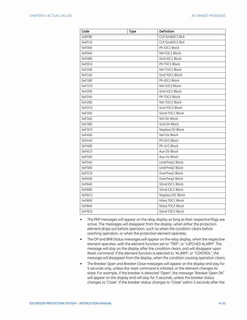
CHAPTER 4: ACTUAL VALUES A4 TARGET MESSAGES
350 FEEDER PROTECTION SYSTEM – INSTRUCTION MANUAL 4–33
• The PKP messages will appear on the relay display as long as their respective flags are active. The messages will disappear from the display, when either the protection element drops out before operation, such as when the condition clears before reaching operation, or when the protection element operates.
• The OP and BKR Status messages will appear on the relay display, when the respective element operates, with the element function set to “TRIP”, or “LATCHED ALARM”. The message will stay on the display after the condition clears, and will disappear upon Reset command. If the element function is selected to “ALARM”, or “CONTROL”, the message will disappear from the display, when the condition causing operation clears.
• The Breaker Open and Breaker Close messages will appear on the display and stay for 5 seconds only, unless the reset command is initiated, or the element changes its state. For example, if the breaker is detected “Open”, the message “Breaker Open OK” will appear on the display and will stay for 5 seconds, unless the breaker status changes to “Close”. If the breaker status changes to "Close" within 5 seconds after the
0xEF80 CLP GndIOC1 BLK
0xEFC0 CLP GndIOC2 BLK
0xF000 Ph IOC1 Block
0xF040 Ntrl IOC1 Block
0xF080 Gnd IOC1 Block
0xF0C0 Ph TOC1 Block
0xF100 Ntrl TOC1 Block
0xF140 Gnd TOC1 Block
0xF180 Ph IOC2 Block
0xF1C0 Ntrl IOC2 Block
0xF200 Gnd IOC2 Block
0xF240 Ph TOC2 Block
0xF280 Ntrl TOC2 Block
0xF2C0 Gnd TOC2 Block
0xF300 SGnd TOC1 Block
0xF340 Ntrl Dir Block
0xF380 Gnd Dir Block
0xF3C0 NegSeq OV Block
0xF400 Ntrl OV Block
0xF440 Ph OV1 Block
0xF480 Ph UV1 Block
0xF4C0 Aux OV Block
0xF500 Aux UV Block
0xF540 UndrFreq1 Block
0xF580 UndrFreq2 Block
0xF5C0 OverFreq1 Block
0xF600 OverFreq2 Block
0xF640 SGnd IOC1 Block
0xF680 SGnd IOC2 Block
0xF6C0 NegSeq IOC Block
0xF800 NSeq TOC1 Block
0xF840 NSeq TOC2 Block
0xF9C0 SGnd TOC2 Block
Code Type Definition
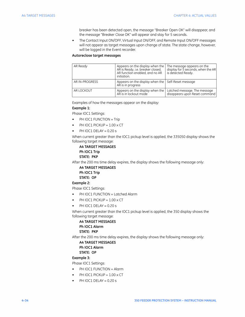
4–34 350 FEEDER PROTECTION SYSTEM – INSTRUCTION MANUAL
A4 TARGET MESSAGES CHAPTER 4: ACTUAL VALUES
breaker has been detected open, the message “Breaker Open OK” will disappear, and the message “Breaker Close OK” will appear and stay for 5 seconds.
• The Contact Input ON/OFF, Virtual Input ON/OFF, and Remote Input ON/OFF messages will not appear as target messages upon change of state. The state change, however, will be logged in the Event recorder.
Autoreclose target messages
Examples of how the messages appear on the display:Example 1:Phase IOC1 Settings:• PH IOC1 FUNCTION = Trip• PH IOC1 PICKUP = 1.00 x CT• PH IOC1 DELAY = 0.20 sWhen current greater than the IOC1 pickup level is applied, the 335050 display shows the following target message:
A4 TARGET MESSAGESPh IOC1 TripSTATE: PKP
After the 200 ms time delay expires, the display shows the following message only:A4 TARGET MESSAGESPh IOC1 TripSTATE: OP
Example 2:Phase IOC1 Settings:• PH IOC1 FUNCTION = Latched Alarm• PH IOC1 PICKUP = 1.00 x CT• PH IOC1 DELAY = 0.20 sWhen current greater than the IOC1 pickup level is applied, the 350 display shows the following target message:
A4 TARGET MESSAGESPh IOC1 AlarmSTATE: PKP
After the 200 ms time delay expires, the display shows the following message only:A4 TARGET MESSAGESPh IOC1 AlarmSTATE: OP
Example 3:Phase IOC1 Settings:• PH IOC1 FUNCTION = Alarm• PH IOC1 PICKUP = 1.00 x CT• PH IOC1 DELAY = 0.20 s
AR Ready Appears on the display when the AR is Ready, i.e. breaker closed, AR function enabled, and no AR initiation.
The message appears on the display for 5 seconds, when the AR is detected Ready.
AR IN-PROGRESS Appears on the display when the AR is in progress
Self-Reset message
AR LOCKOUT Appears on the display when the AR is in lockout mode
Latched message. The message disappears upon Reset command

CHAPTER 4: ACTUAL VALUES A4 TARGET MESSAGES
350 FEEDER PROTECTION SYSTEM – INSTRUCTION MANUAL 4–35
When current greater than the IOC1 pickup level is applied, the 350 display shows the following target message:
A4 TARGET MESSAGESPh IOC1 AlarmSTATE: PKP
After the 200 ms time delay expires, the display shows the following message only:A4 TARGET MESSAGESPh IOC1 AlarmSTATE: OP
NOTE
NOTE: Once the condition clears, the target message will disappear.

4–36 350 FEEDER PROTECTION SYSTEM – INSTRUCTION MANUAL
A4 TARGET MESSAGES CHAPTER 4: ACTUAL VALUES

350 FEEDER PROTECTION SYSTEM – INSTRUCTION MANUAL 5–1
350 Feeder Protection System
Chapter 5: Quick setup - Front control panel
Digital EnergyMultilin
Quick setup - Front control panel
The “Quick Setup” utility is part of the 350 relay main menu, and can be used for quick and easy programming. Power system parameters, and settings for some simple over-current elements can be easily set. Use the “Quick Setup” utility to program the following:Power System Data:• Phase CT Primary• Ground CT Primary• VT Secondary voltage• Aux VT Secondary Voltage• Aux VT RatioOvercurrent Protection:• Phase TOC• Ground TOC• Neutral TOC• Phase IOC• Ground IOC • Neutral IOC
NOTE
NOTE: Ensure the relay is in "Relay Ready" state before using Quick Setup.
5–2 350 FEEDER PROTECTION SYSTEM – INSTRUCTION MANUAL
CHAPTER 5: QUICK SETUP - FRONT CONTROL PANEL
Figure 1: Quick Setup menu
ACTUAL VALUES
QUICK SETUP
SETPOINTS
MAINTENANCE
QUICK SETUP
RELAY STATUS
NOMINAL FREQUENCY
PH CT PRIMARY
[SENS] GND CT
VT SEC. VOLTAGE
VT RATIO
AUX VT SECONDARY
AUX VT RATIO
PH TOC FUNCTION
GND TOC FUNCTION
NTRL TOC FUNCTION
PH IOC1 FUNCTION
GND IOC1 FUNCTION
NTRL IOC1 FUNCTION
PRIMARY
▼
898788A1.cdr
PHASE TOC
PH TOC PICKUP
PH TOC CURVE
PH TOC TDM
▼
GROUND TOC
GROUND TOC PICKUP
GROUND TOC CURVE
GROUND TOC TDM
▼
NEUTRAL TOC
NTRL TOC PICKUP
NTRL TOC CURVE
NTRL TOC TDM
▼
PHASE IOC1
PH IOC1 PICKUP
GROUND IOC1
GND IOC1 PICKUP
NEUTRAL IOC1
NTRL IOC1 PICKUP
CHAPTER 5: QUICK SETUP - FRONT CONTROL PANEL QUICK SETUP SETTINGS
350 FEEDER PROTECTION SYSTEM – INSTRUCTION MANUAL 5–3
Quick Setup settings
The setpoints below can be programmed under the "Quick Setup" menu.Note that monitoring of Breaker Status via 52a, 52b, or both of these contacts,, should be programmed under SETPOINTS > SYSTEM SETUP > BREAKER.PATH: QUICK SETUP >
PH CT PRIMARY
Range: 1 A to 6000 A in steps of 1Default: 500 A
GND CT PRIMARY
Range: 1 A to 6000 A in steps of 1Default: 50 A
VT CONNECTION
Range: Wye, DeltaDefault: Wye
VT SEC VOLTAGE
Range: 50 V to 240 V in steps of 1Default: 120 V
VT RATIO
Range: 1:1 to 5000:1 in steps of 1Default: 1:1
AUX VT SECONDARY
Range: 50 V to 240 V in steps of 1Default: 110 V
AUX VT RATIO
Range: 1:1 to 5000:1 in steps of 1Default: 1:1
PH TOC FUNCTION
Range: Trip, Disabled, Latched Alarm, AlarmDefault: Trip
↘PH TOC PICKUP
Range: 0.04 to 20.00 x CTDefault: 1.00 x CT
PH TOC CURVE
Range: ANSI Extremely/Very/Moderately/Normally Inverse, Definite Time, IEC Curve A/B/C and Short, IAC Extreme/Very/Inverse/Short, User Curve, FlexCurve™ A/B (programmable curves)Default: Extremely Inverse
PH TOC TDM
Range: 0.50 to 20.00Default: 1.00
5–4 350 FEEDER PROTECTION SYSTEM – INSTRUCTION MANUAL
QUICK SETUP SETTINGS CHAPTER 5: QUICK SETUP - FRONT CONTROL PANEL
GND TOC FUNCTION
Range: Disabled, Trip, Latched Alarm, AlarmDefault: Disabled
↘GND TOC PICKUP
Range: 0.04 to 20 x CTDefault: 1.00 x CT
GND TOC CURVE
Range: ANSI Extremely/Very/Moderately/Normally Inverse; Definite Time; IEC Curve A/B/C /Short Inverse; IAC Extreme/Very/Inverse/Short Inverse; User Curve, FlexCurve™ A/B (programmable curves)Default: Extremely Inverse
GND TOC TDM
Range: 0.50 to 20.00Default: 1.00
SENS GND TOC FUNCTION [WHEN SPECIFICALLY ORDERED]Range: Disabled, Trip, Latched Alarm, AlarmDefault: Disabled
↘SENS GND TOC PICKUP
Range: 0.005 to 3.000 x CTDefault: 1.000 x CT
SENS GND TOC CURVE
Range: ANSI Extremely/Very/Moderately/Normally Inverse; Definite Time; IEC Curve A/B/C /Short Inverse; IAC Extreme/Very/Inverse/Short Inverse; User Curve, FlexCurve™ A/B (programmable curves)Default: Extremely Inverse
SENS GND TOC TDM
Range: 0.50 to 20.00Default: 1.0
NTRL TOC FUNCTION
Range: Disabled, Trip, Latched Alarm, AlarmDefault: Disabled
↘NTRL TOC PICKUP
Range: 0.04 to 20.00 x CTDefault: 1.00 x CT
NTRL TOC CURVE
Range: ANSI Extremely/Very/Moderately/Normally Inverse, Definite Time, IEC Curve A/B/C and Short, IAC Extreme/Very/Inverse/Short, User Curve, FlexCurve™ A/B (programmable curves)Default: Extremely Inverse
NTRL TOC TDM
Range: 0.50 to 20.00Default: 1.00

CHAPTER 5: QUICK SETUP - FRONT CONTROL PANEL QUICK SETUP SETTINGS
350 FEEDER PROTECTION SYSTEM – INSTRUCTION MANUAL 5–5
PH IOC1 FUNCTION
Range: Disabled, Trip, Latched Alarm, AlarmDefault: Disabled
↘PH IOC1 PICKUP
Range: 0.05 to 20.00 x CTDefault: 1.00 x CT
GND IOC1 FUNCTION
Range: Disabled, Trip, Latched Alarm, AlarmDefault: Disabled
↘GND IOC1 PICKUP
Range: 0.05 to 20.00 x CTDefault: 1.00 x CT
SENS GND IOC1 FUNCTION [WHEN SPECIFICALLY ORDERED]Range: Disabled, Trip, Latched Alarm, AlarmDefault: Disabled
↘SENS GND IOC1 PICKUP
Range: 0.005 to 3.000 x CTDefault: 1.000 x CT
NTRL IOC1 FUNCTION
Range: Disabled, Trip, Latched Alarm, AlarmDefault: Disabled
↘NTRL IOC1 PICKUP
Range: 0.05 to 20.00 x CTDefault: 1.00 x CT
NOTE
NOTE: The settings changed using the Quick Setup menu, are available for review and modification by navigating through S2 SYSTEM SETUP and S3 PROTECTION > SETPOINT GROUP 1 in the SETPOINTS main menu.
menu are available for rew

5–6 350 FEEDER PROTECTION SYSTEM – INSTRUCTION MANUAL
QUICK SETUP SETTINGS CHAPTER 5: QUICK SETUP - FRONT CONTROL PANEL

350 FEEDER PROTECTION SYSTEM – INSTRUCTION MANUAL 6–1
350 Feeder Protection System
Chapter 6: Setpoints
Digital EnergyMultilin
Setpoints
Setpoints Main Menu
The 350 has a considerable number of programmable setpoints, all of which make the relay extremely flexible. These setpoints have been grouped into a variety of pages and subpages as shown below. Each setpoints menu has a section that describes in detail the setpoints found on that menu.
6–2 350 FEEDER PROTECTION SYSTEM – INSTRUCTION MANUAL
SETPOINTS MAIN MENU CHAPTER 6: SETPOINTS
Figure 1: Main Setpoints menu
Setpoint entry methodsBefore placing the relay into “IN SERVICE” mode, setpoints defining system characteristics, inputs, relay outputs, and protection settings must be entered using one of the following methods:
S3 PROTECTION
SETPOINT GROUP 1
SETPOINT GROUP 2
S5 INPUTS/OUTPUTS
CONTACT INPUTS
OUTPUT RELAYS
VIRTUAL INPUTS
S4 CONTROLS
CHANGE SEPNT GROUP
VIRTUAL INPUTS
LOGIC ELEMENTS
COLD LOAD PICKUP
BREAKER FAIL
AUTORECLOSE
BREAKER CONTROL
▼
S2 SYSTEM SETUP
CURRENT SENSING
VOLTAGE SENSING
POWER SYSTEM
BREAKER
USER CURVE
FLEXCURVE A
FLEXCURVE B
▼
S1 RELAY SETUP
CLOCK
PASSWORD SECURITY
COMMUNICATIONS
EVENT RECORDER
TRANSIENT RECDR
FRONT PANEL
INSTALLATION
▼
SETPOINTS
S1 RELAY SETUP
S2 SYSTEM SETUP
S3 PROTECTION
S4 CONTROLS
S5 INPUTS/OUTPUTS
▼
S3 SETPOINT GROUP 1
PHASE TOC
PHASE IOC1
PHASE IOC2
[SENS] GROUND TOC
[SENS] GROUND IOC1
[SENS]
NEUTRAL TOC
NEUTRAL IOC1
NEUTRAL IOC2
NEG SEQ IOC
PHASE UV
PHASE OV
NEUTRAL OV
NEGATIVE SEQ OV
AUXILIARY UV
AUXILIARY OV
UNDER-FREQUENCY1
UNDER-FREQUENCY2
OVER-FREQUENCY1
OVER-FREQUENCY2
GROUND IOC2
[SENS] GND DIR
NTRL DIR
THERMAL MODEL
▼
S3 SETPOINT GROUP 2
PHASE TOC
PHASE IOC1
PHASE IOC2
[SENS] GROUND TOC
[SENS] GROUND IOC1
[SENS]
NEUTRAL TOC
NEUTRAL IOC1
NEUTRAL IOC2
NEG SEQ IOC
PHASE UV
PHASE OV
NEUTRAL OV
NEGATIVE SEQ OV
AUXILIARY UV
AUXILIARY OV
UNDER-FREQUENCY1
UNDER-FREQUENCY2
OVER-FREQUENCY1
OVER-FREQUENCY2
GROUND IOC2
[SENS] GND DIR
THERMAL MODEL
NTRL DIR
▼
898757A1.cdr

CHAPTER 6: SETPOINTS SETPOINTS MAIN MENU
350 FEEDER PROTECTION SYSTEM – INSTRUCTION MANUAL 6–3
• Front panel, using the keypad and the display.• Front USB port, or rear RS485, Ethernet 100 FX, Ethernet 10/100 BaseT (optional) port,
and a computer running the EnerVista SR3 Setup software supplied with the relay.• Rear serial RS485, and a SCADA system running user-written software.Any of these methods can be used to enter the same information. A computer, however, makes entry much easier. Files can be stored and downloaded for fast, error free entry when a computer is used. To facilitate this process, the GE EnerVista CD with the EnerVista SR3 Setup software is supplied with the relay.The relay leaves the factory with setpoints programmed to default values, and these values are shown throughout the setpoint message illustrations. Some of these factory default values can be left unchanged whenever they satisfy the application.At a minimum, the S2 SYSTEM SETUP setpoints must be entered for the system to function correctly. To safeguard against the installation of a relay into which setpoints have not been entered, the Relay Not Ready self-test warning is displayed. In addition, the critical failure relay will be de-energized. Once the relay has been programmed for the intended application, the S1 RELAY SETUP/ INSTALLATION/ RELAY STATUS setpoint should be changed from “Not Ready” (the default) to “Ready”.
Common setpointsTo make the application of this device as simple as possible, similar methods of operation and similar types of setpoints are incorporated in various features. Rather than repeat operation descriptions for this class of setpoint throughout the manual, a general description is presented in this overview. Details that are specific to a particular feature are included in the discussion of the feature. The form and nature of these setpoints is described below.• FUNCTION setpoint: The <ELEMENT_NAME> FUNCTION setpoint determines the
operational characteristic of each feature. The range for these setpoints is two or more of: “Disabled”, “Enabled”, “Trip”, “Alarm”, “Latched Alarm”, and “Control”.If <ELEMENT_NAME > FUNCTION: “Disabled”, the feature is not operational. If <ELEMENT_NAME > FUNCTION: “Enabled”, the feature is operational.If <ELEMENT_NAME > FUNCTION: “Trip”, then the feature is operational. When an output is generated, the feature declares a Trip condition, and operates the Trip relay (output relay 1), any other selected aux. output relays, and displays the appropriate trip message.If <ELEMENT_NAME> FUNCTION: “Alarm” or “Latched Alarm”, then the feature is operational. When an output is generated, the feature declares an “Alarm” condition which operates any selected aux.output relays and displays the appropriate alarm message.If <ELEMENT_NAME> FUNCTION: “Control” the feature is operational. When an output is generated, the feature operates any selected output relays. The “Trip”, “Alarm”, and “Control” function setpoint values are also used to select those operations that will be stored in the Event Recorder.
• RELAYS (3–6) setpoint: The <ELEMENT_NAME> RELAYS (3-6) setpoint selects the relays required to operate when the feature generates an output. The range is any combination of the Auxiliary relays (Auxiliary Relays 3 to 6).
• PICKUP setpoint: The <ELEMENT_NAME> PICKUP setpoint selects the threshold above which the measured parameter causes an output from the measuring element.
• DELAY setpoint: The <ELEMENT_NAME> DELAY setpoint selects a fixed time interval to delay an input signal from appearing at the output. The time from a contact input change of state or an AC parameter input level change to a contact closure of the 1 Trip relay, is the time selected as time delay in this setpoint plus approximately up to 2 power frequency periods.

6–4 350 FEEDER PROTECTION SYSTEM – INSTRUCTION MANUAL
SETPOINTS MAIN MENU CHAPTER 6: SETPOINTS
• DIRECTION setpoint: The <ELEMENT_NAME> DIRECTION setpoint is available for overcurrent features which are subject to control from a directional element. The range is “Disabled”, “Forward”, and “Reverse”. If set to “Disabled”, the element is allowed to operate for current flow in any direction. There is no supervision from the directional element. If set to “Forward”, the element is allowed to operate for current flow in the forward direction only, as determined by the directional element. If set to “Reverse”, the element is allowed to operate for current flow in the reverse direction only, as determined by the directional element.
Logic diagramsThe logic diagrams provide a complete comprehensive understanding of the operation of each feature. These sequential logic diagrams illustrate how each setpoint, input parameter, and internal logic is used in the feature to obtain an output. In addition to these logic diagrams, written descriptions are provided in the setpoints chapter which includes each feature.• Setpoints: Shown as a block with a heading labeled ‘SETPOINT’. The exact wording of
the displayed setpoint message identifies the setpoint. Major functional setpoint selections are listed below the name and are incorporated in the logic.
• Compensator Blocks: Shown as a block with an inset box labeled ‘RUN’ with the associated pickup/dropout setpoint shown directly above. Element operation of the detector is controlled by the signal entering the ‘RUN’ inset. The measurement/ comparison can only be performed if a logic ‘1’ is provided at the ‘RUN’ input. The relationship between setpoint and input parameter is indicated by the following symbols: “<” (less than) " >” (greater than), etc.
• Time Delays: Shown as a block with either pickup, drop-out, or both; times in milliseconds or seconds. If the delay is adjustable, associated delay setpoint is shown with block SETPOINT on the top of the delay block.
• LED Indicators: Shown as the following schematic symbol, □. The exact wording of the front panel label identifies the indicator.
• Logic: Described with basic logic gates (AND, OR, XOR, NAND, NOR). The inverter (logical NOT), is shown as a circle: ○.
Setting text abbreviationsThe following abbreviations are used in the setpoints pages.• A: amperes• kA: kiloamperes• V: volts• kV: kilovolts• kW: kilowatts• kVar: kilovars• kVA: kilo-volt-amperes• AUX: auxiliary• COM, Comms: communications• CT: current transformer• GND: ground• Hz: Hertz• MAX: maximum• MIN: minimum• SEC, s: seconds

CHAPTER 6: SETPOINTS SETPOINTS MAIN MENU
350 FEEDER PROTECTION SYSTEM – INSTRUCTION MANUAL 6–5
• UV: undervoltage• OV: overvoltage• VT: voltage transformer• Ctrl: control• Hr & hr: hour• O/L: overload
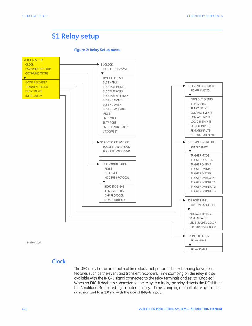
6–6 350 FEEDER PROTECTION SYSTEM – INSTRUCTION MANUAL
S1 RELAY SETUP CHAPTER 6: SETPOINTS
S1 Relay setup
Figure 2: Relay Setup menu
ClockThe 350 relay has an internal real time clock that performs time stamping for various features such as the event and transient recorders. Time stamping on the relay is also available with the IRIG-B signal connected to the relay terminals and set to “Enabled”. When an IRIG-B device is connected to the relay terminals, the relay detects the DC shift or the Amplitude Modulated signal automatically. Time stamping on multiple relays can be synchronized to ± 1.0 ms with the use of IRIG-B input.
S1 ACCESS PASSWORDS
LOC SETPOINTS PSWD
LOC CONTROLS PSWD
S1 CLOCK
DATE (MM/DD/YYYY)
TIME (HH:MM:SS)
DLS ENABLE
DLS START MONTH
DLS START WEEK
DLS END MONTH
DLS END WEEK
IRIG-B
SNTP MODE
SNTP PORT
SNTP SERVER IP ADR
UTC OFFSET
DLS START WEEKDAY
DLS END WEEKDAY
▼
S1 RELAY SETUP
CLOCK
PASSWORD SECURITY
COMMUNICATIONS
EVENT RECORDER
TRANSIENT RECDR
FRONT PANEL
INSTALLATION
▼
898764A1.cdr
S1 COMMUNICATIONS
RS485
ETHERNET
DNP PROTOCOL
61850 PROTOCOL
MODBUS PROTOCOL
IEC60870-5-103
▼
IEC60870-5-104
S1 EVENT RECORDER
PICKUP EVENTS
TRIP EVENTS
ALARM EVENTS
CONTROL EVENTS
DROPOUT EVENTS
CONTACT INPUTS
LOGIC ELEMENTS
VIRTUAL INPUTS
REMOTE INPUTS
SETTING DATE/TIME
▼
S1 FRONT PANEL
MESSAGE TIMEOUT
SCREEN SAVER
FLASH MESSAGE TIME
LED BKR OPEN COLOR
LED BKR CLSD COLOR
▼
S1 INSTALLATION
RELAY NAME
RELAY STATUS
▼
S1 TRANSIENT RECDR
TRIGGER MODE
TRIGGER POSITION
BUFFER SETUP
TRIGGER ON PKP
TRIGGER ON DPO
TRIGGER ON TRIP
TRIGGER ON ALARM
TRIGGER ON INPUT 1
TRIGGER ON INPUT 2
TRIGGER ON INPUT 3
▼

CHAPTER 6: SETPOINTS S1 RELAY SETUP
350 FEEDER PROTECTION SYSTEM – INSTRUCTION MANUAL 6–7
The following path is available using the keypad. For instructions on how to use the keypad, please refer to Chapter 3 - Working with the Keypad.PATH: SETPOINTS > S1 RELAY SETUP > CLOCK
DATE: (MM/DD/YYYY)
Range: Month: Jan, Feb, Mar, Apr, May, Jun, Jul, Aug, Sep, Oct, Nov, Dec Day: 1 to 31 Year: 2009 to 2099Default: Jan 15 2009
This setting sets the date in the specified format.
TIME: (HH:MM:SS)
Range: 0 to 23: 0 to 59: 0 to59Default: 03:15:50
This setting sets the time in the specified format.
DLS ENABLE
Range: Disabled, EnabledDefault: Disabled
PATH: SETPOINTS > S1 RELAY SETUP > CLOCK > DLS ENABLE [ENABLED]
DLS START MONTH:
Range: Not Set, January, February, March, April, May, June, July, August, September, October, November, DecemberDefault: Not Set
This setting sets the month for the DLS start time.
DLS START WEEK:
Range: Not Set, 1st, 2nd, 3rd, 4th, LastDefault: Not Set
This setting sets the week of the month for the DLS start time.
DLS START WEEKDAY:
Range: Not Set, Mon, Tue, Wed, Thu, Fri, Sat, SunDefault: Not Set
This setting sets the weekday for the DLS start time.
DLS END MONTH:
Range: Not Set, January, February, March, April, May, June, July, August, September, October, November, DecemberDefault: Not Set
This setting sets the month for the end of the DLS time.
DLS END WEEK:
Range: Not Set, 1st, 2nd, 3rd, 4th, LastDefault: Not Set
This setting sets the week of the month for the end of the DLS time.
DLS END WEEKDAY:
Range: Not Set, Mon, Tue, Wed, Thu, Fri, Sat, SunDefault: Not Set
This setting sets the weekday for the end of the DLS time.PATH: SETPOINTS > S1 RELAY SETUP > CLOCK

6–8 350 FEEDER PROTECTION SYSTEM – INSTRUCTION MANUAL
S1 RELAY SETUP CHAPTER 6: SETPOINTS
IRIG-B:
Range: Disabled, EnabledDefault: Disabled
This setting enables the IRIG-B signal for time stamp synchronization.
1. Set the IRIG-B to “Enabled” if the IRIG-B device is connected to the relay IRIG-B terminals. The relay will display the message “IRIG-B failure” in the case of either no IRIG-B signal from the connected IRIG-B device, or when the signal cannot be decoded.
2. Set the date and time per the specified date and time format.3. Set the start time of the Daylight Saving (DLS) time, by selecting the Month, the Week
of the month, and the Weekday defining the beginning of the Daylight Saving time. 4. Set the end of the Daylight Saving time, by selecting the Month, the Week of the
month, and the Weekday defining the end of the Daylight Saving time.The clock has a super-capacitor back-up, so that time, date, and events will be kept for up to 3 days in cases of loss of relay control power.
Password securityPassword security features are designed into the relay to provide protection against unauthorized setpoint changes and control. The relay has programmable passwords for both Local and Remote access, which can be used to allow setpoint changes and command execution from both the front panel and the communications ports. These passwords consist of 3 to 10 alphanumeric characters. The Local and the Remote passwords are initially set after entering in a Master Reset Password (MRP). The Master Reset Password (MRP) is set to “NULL” when the relay is shipped from the factory. When the MRP is programmed to “NULL” all password security is disabled. The remote user may choose to allow the local user to change the local passwords.Each interface (RS485, Ethernet, USB, and front panel keypad) is independent of one another, meaning that enabling setpoint access on one interface does not enable access for any of the other interfaces (i.e., the password must be explicitly entered via the interface from which access is desired).The EnerVista SR3 Setup software incorporates a facility for programming the relay’s passwords as well as enabling/disabling setpoint access. For example, when an attempt is made to modify a setpoint but access is restricted, the program will prompt the user to enter the password and send it to the relay before the setpoint can actually be written to the relay. If a SCADA system is used for relay programming, it is up to the programmer to incorporate appropriate security for the application.Aside from being logged out of security, which allows the user to read setpoints and actual values only, three levels of security access are provided: Setpoint Level, Control Level, and Master Level. The Setpoint and Control Levels can be attained either locally using the Local passwords (USB port and keypad), or remotely using the Remote passwords (RS485 and Ethernet ports). The user can have either Setpoint or Control Level active, but not both simultaneously from the same interface. The Master Level is used for setting and resetting of passwords, and includes all Setpoint and Control Level access rights. The Master Level cannot be attained from the keypad. The Master Reset Password must be 8 to 10 characters in length, and must contain at least 2 letters and 2 numbers. The Master Level can define whether the local user is permitted to change Local Passwords without having to enter the Master Level. The Master Reset Password is encrypted, and is not viewable from the keypad. If the Master Reset Password is lost, the user should contact the factory to decrypt the Master Reset Password.
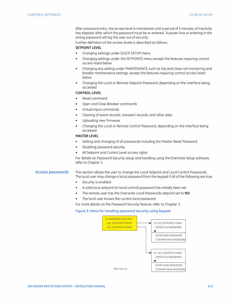
CHAPTER 6: SETPOINTS S1 RELAY SETUP
350 FEEDER PROTECTION SYSTEM – INSTRUCTION MANUAL 6–9
After password entry, the access level is maintained until a period of 5 minutes of inactivity has elapsed, after which the password must be re-entered. A power-loss or entering in the wrong password will log the user out of security.Further definition of the access levels is described as follows:SETPOINT LEVEL• Changing settings under QUICK SETUP menu• Changing settings under the SETPOINTS menu except the features requiring control
access listed below• Changing any setting under MAINTENANCE such as trip and close coil monitoring and
breaker maintenance settings, except the features requiring control access listed below
• Changing the Local or Remote Setpoint Password, depending on the interface being accessed
CONTROL LEVEL• Reset command• Open and Close Breaker commands• Virtual Input commands• Clearing of event records, transient records, and other data• Uploading new firmware• Changing the Local or Remote Control Password, depending on the interface being
accessedMASTER LEVEL• Setting and changing of all passwords including the Master Reset Password• Disabling password security• All Setpoint and Control Level access rightsFor details on Password Security setup and handling using the EnerVista Setup software, refer to Chapter 3.
Access passwords This section allows the user to change the Local Setpoint and Local Control Passwords. The local user may change a local password from the keypad if all of the following are true:• Security is enabled• A valid local setpoint (or local control) password has initially been set• The remote user has the Overwrite Local Passwords setpoint set to NO• The local user knows the current local password.For more details on the Password Security feature, refer to Chapter 3.
Figure 3: Menu for handling password security using keypad
S1 PASSWORD SECURITY
LOC SETPOINTS PSWD
LOC CONTROLS PSWD
898772A1.cdr
S1 LOC SETPOINTS PSWD
ENTER NEW
CONFIRM NEW
ENTER OLD PASSWORD
PASSWORD
PASSWORD
▼
S1 LOC CONTROLS PSWD
ENTER NEW PASSWORD
CONFIRM NEW PASSWORD
ENTER OLD PASSWORD
▼

6–10 350 FEEDER PROTECTION SYSTEM – INSTRUCTION MANUAL
S1 RELAY SETUP CHAPTER 6: SETPOINTS
The following steps describe how to change the Local Setpoints Password from the keypad. Similar steps are followed to change the Local Control Password.ENTER OLD PASSWORDThe user is prompted to enter the current Local Setpoints Password. User the value up/down keys to select characters, and use the message left/right keys to move the cursor. Press the Enter key when done. An INVALID PASSWORD message will appear if a wrong password is entered, security is disabled, the password has not been originally set, or the local user does not have the rights to change the password. In addition, the user will be automatically logged out of security from the keypad. If the correct password was entered, the user is now logged in to the Setpoints Level from the keypad, and will be prompted to enter a new password.ENTER NEW PASSWORDThe user is prompted to enter a new Local Setpoints Password. A valid password is alphanumeric, and is 3 to 10 characters in length. An INVALID PASSWORD message will appear if the new password does not meet the password requirements. If a valid password was entered, the user will be prompted to re-enter the new password.CONFIRM PASSWORDThe user is prompted to re-enter the new Local Setpoints Password. If the passwords do not match, an ENTRY MISMATCH message will appear, the password will remain unchanged, and the user will be returned to the Enter New Password page. If the passwords match, a PASSWORD CHANGED message will appear indicating the Local Setpoints Password has successfully been updated.
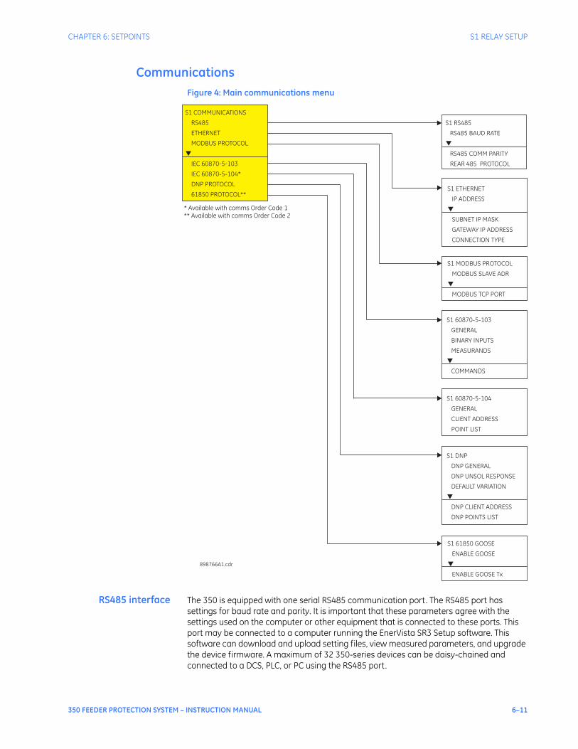
CHAPTER 6: SETPOINTS S1 RELAY SETUP
350 FEEDER PROTECTION SYSTEM – INSTRUCTION MANUAL 6–11
CommunicationsFigure 4: Main communications menu
RS485 interface The 350 is equipped with one serial RS485 communication port. The RS485 port has settings for baud rate and parity. It is important that these parameters agree with the settings used on the computer or other equipment that is connected to these ports. This port may be connected to a computer running the EnerVista SR3 Setup software. This software can download and upload setting files, view measured parameters, and upgrade the device firmware. A maximum of 32 350-series devices can be daisy-chained and connected to a DCS, PLC, or PC using the RS485 port.
S1 RS485
RS485 BAUD RATE
RS485 COMM PARITY
REAR 485 PROTOCOL
▼
S1 COMMUNICATIONS
RS485
ETHERNET
MODBUS PROTOCOL
DNP PROTOCOL
61850 PROTOCOL**
IEC 60870-5-103
IEC 60870-5-104*
▼
898766A1.cdr
S1 60870-5-103
GENERAL
BINARY INPUTS
MEASURANDS
COMMANDS
▼
S1 MODBUS PROTOCOL
MODBUS TCP PORT
MODBUS SLAVE ADR
▼
S1 DNP
DNP GENERAL
DNP UNSOL RESPONSE
DEFAULT VARIATION
DNP CLIENT ADDRESS
DNP POINTS LIST
▼
S1 60870-5-104
GENERAL
CLIENT ADDRESS
POINT LIST
S1 61850 GOOSE
ENABLE GOOSE
▼
ENABLE GOOSE Tx
* Available with comms Order Code 1** Available with comms Order Code 2
S1 ETHERNET
SUBNET IP MASK
GATEWAY IP ADDRESS
CONNECTION TYPE
IP ADDRESS
▼

6–12 350 FEEDER PROTECTION SYSTEM – INSTRUCTION MANUAL
S1 RELAY SETUP CHAPTER 6: SETPOINTS
Select the Settings > Communications > Serial Ports menu item in the EnerVista SR3 Setup program, or the SETPOINTS > S1 RELAY SETUP > COMMUNICATIONS > RS485 path on the display, to configure the serial port.
Figure 5: Serial port configuration settings
The following settings are available to configure the RS485 port.
BAUD RATE
Range: 9600, 19200, 38400, 57600, 115200Default: 115200
This setting specifies the baud rate (bits per second) for the RS485 port.
PARITY
Range: None, Odd, EvenDefault: None
This setting specifies the parity for the RS485 port.
Ethernet Select the Setpoints > S1 Relay Setup > Communications > Ethernet menu item in the EnerVista SR3 Setup program, or the SETPOINTS > S1 RELAY SETUP > COMMUNICATIONS > ETHERNET path on the display, to configure the Ethernet port.The following settings are available to configure the Ethernet port.
IP Address
Range: Standard IP Address formatDefault: 000.000.000.000
This setting specifies the IP Address for the Ethernet port.
Subnet IP Mask
Range: Standard IP Address formatDefault: 255.255.255.000
This setting specifies the Subnet IP Mask setting for the Ethernet port.
Gateway IP Address
Range: Standard IP Address formatDefault: 000.000.000.000
This setting specifies the Gateway IP Address for the Ethernet port.
Connection Type
Range: Copper, fiberDefault: Copper
This setting specifies the connection type (Copper or Fiber) used for Ethernet communication.
NOTE
NOTE: When changing Ethernet settings, power to the relay must be cycled in order for the new settings to become active.
Modbus The Modicon Modbus protocol is supported by the 350. Modbus is available via the RS485 serial link (Modbus RTU). The 350 always acts as a slave device, meaning that it never initiates communications; it only listens and responds to requests issued by a master
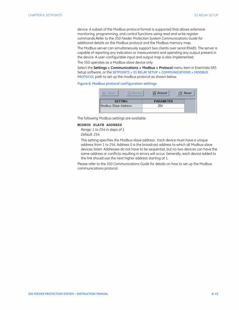
CHAPTER 6: SETPOINTS S1 RELAY SETUP
350 FEEDER PROTECTION SYSTEM – INSTRUCTION MANUAL 6–13
device. A subset of the Modbus protocol format is supported that allows extensive monitoring, programming, and control functions using read and write register commands.Refer to the 350 Feeder Protection System Communications Guide for additional details on the Modbus protocol and the Modbus memory map.The Modbus server can simultaneously support two clients over serial RS485. The server is capable of reporting any indication or measurement and operating any output present in the device. A user-configurable input and output map is also implemented.The 350 operates as a Modbus slave device onlySelect the Settings > Communications > Modbus > Protocol menu item in EnerVista SR3 Setup software, or the SETPOINTS > S1 RELAY SETUP > COMMUNICATIONS > MODBUS PROTOCOL path to set up the modbus protocol as shown below.
Figure 6: Modbus protocol configuration settings
The following Modbus settings are available:
MODBUS SLAVE ADDRESS
Range: 1 to 254 in steps of 1Default: 254
This setting specifies the Modbus slave address . Each device must have a unique address from 1 to 254. Address 0 is the broadcast address to which all Modbus slave devices listen. Addresses do not have to be sequential, but no two devices can have the same address or conflicts resulting in errors will occur. Generally, each device added to the link should use the next higher address starting at 1.
Please refer to the 350 Communications Guide for details on how to set up the Modbus communications protocol.
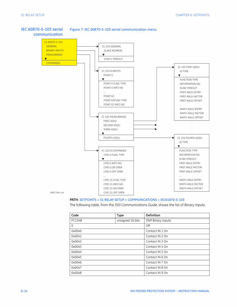
6–14 350 FEEDER PROTECTION SYSTEM – INSTRUCTION MANUAL
S1 RELAY SETUP CHAPTER 6: SETPOINTS
IEC 60870-5-103 serialcommunication
Figure 7: IEC 60870-5-103 serial communication menu
PATH: SETPOINTS > S1 RELAY SETUP > COMMUNICATIONS > IEC61870-5-103The following table, from the 350 Communications Guide, shows the list of Binary Inputs.
S1 103 FIRST ASDU
ID TYPE
FUNCTION TYPE
INFORMATION NO
SCAN TIMEOUT
FIRST ANLG ENTRY
FIRST ANLG FACTOR
FIRST ANLG OFFSET
...
NINTH ANLG ENTRY
NINTH ANLG FACTOR
NINTH ANLG OFFSET
▼
S1 103 GENERAL
SLAVE ADDRESS
SYNCH TIMEOUT
▼
898770A1.cdr
S1 103 MEASURANDS
FIRST ASDU
SECOND ASDU
THIRD ASDU
FOURTH ASDU
▼
S1 60870-5-103
GENERAL
BINARY INPUTS
MEASURANDS
COMMANDS
▼
S1 103 B COMMANDS
CMD 0 FUNC TYPE
CMD 0 INFO NO
CMD 0 ON OPER
CMD 0 OFF OPER
...
CMD 15 FUNC TYPE
CMD 15 INFO NO
CMD 15 ON OPER
CMD 15 OFF OPER
▼
S1 103 FOURTH ASDU
ID TYPE
FUNCTION TYPE
INFORMATION NO
SCAN TIMEOUT
FIRST ANLG ENTRY
FIRST ANLG FACTOR
FIRST ANLG OFFSET
...
NINTH ANLG ENTRY
NINTH ANLG FACTOR
NINTH ANLG OFFSET
▼
S1 103 B INPUTS
POINT 0
POINT 0 FUNC TYPE
POINT 0 INFO NO
...
POINT 63
POINT 63FUNC TYPE
POINT 63 INFO NO
▼
.
.
.
.
Code Type Definition
FC134B unsigned 16 bits DNP Binary Inputs
0 Off
0x0040 Contact IN 1 On
0x0041 Contact IN 2 On
0x0042 Contact IN 3 On
0x0043 Contact IN 4 On
0x0044 Contact IN 5 On
0x0045 Contact IN 6 On
0x0046 Contact IN 7 On
0x0047 Contact IN 8 On
0x0048 Contact IN 9 On
CHAPTER 6: SETPOINTS S1 RELAY SETUP
350 FEEDER PROTECTION SYSTEM – INSTRUCTION MANUAL 6–15
0x0049 Contact IN 10 On
0x0060 Contact IN 1 Off
0x0061 Contact IN 2 Off
0x0062 Contact IN 3 Off
0x0063 Contact IN 4 Off
0x0064 Contact IN 5 Off
0x0065 Contact IN 6 Off
0x0066 Contact IN 7 Off
0x0067 Contact IN 8 Off
0x0068 Contact IN 9 Off
0x0069 Contact IN 10 Off
0x0080 Virtual IN 1 On
0x0081 Virtual IN 2 On
0x0082 Virtual IN 3 On
0x0083 Virtual IN 4 On
0x0084 Virtual IN 5 On
0x0085 Virtual IN 6 On
0x0086 Virtual IN 7 On
0x0087 Virtual IN 8 On
0x0088 Virtual IN 9 On
0x0089 Virtual IN 10 On
0x008A Virtual IN 11 On
0x008B Virtual IN 12 On
0x008C Virtual IN 13 On
0x008D Virtual IN 14 On
0x008E Virtual IN 15 On
0x008F Virtual IN 16 On
0x0090 Virtual IN 17 On
0x0091 Virtual IN 18 On
0x0092 Virtual IN 19 On
0x0093 Virtual IN 20 On
0x0094 Virtual IN 21 On
0x0095 Virtual IN 22 On
0x0096 Virtual IN 23 On
0x0097 Virtual IN 24 On
0x0098 Virtual IN 25 On
0x0099 Virtual IN 26 On
0x009A Virtual IN 27 On
0x009B Virtual IN 28 On
0x009C Virtual IN 29 On
0x009D Virtual IN 30 On
0x009E Virtual IN 31 On
0x009F Virtual IN 32 On
0x00A0 Virtual IN 1 Off
0x00A1 Virtual IN 2 Off
0x00A2 Virtual IN 3 Off
0x00A3 Virtual IN 4 Off
Code Type Definition

6–16 350 FEEDER PROTECTION SYSTEM – INSTRUCTION MANUAL
S1 RELAY SETUP CHAPTER 6: SETPOINTS
0x00A4 Virtual IN 5 Off
0x00A5 Virtual IN 6 Off
0x00A6 Virtual IN 7 Off
0x00A7 Virtual IN 8 Off
0x00A8 Virtual IN 9 Off
0x00A9 Virtual IN 10 Off
0x00AA Virtual IN 11 Off
0x00AB Virtual IN 12 Off
0x00AC Virtual IN 13 Off
0x00AD Virtual IN 14 Off
0x00AE Virtual IN 15 Off
0x00AF Virtual IN 16 Off
0x00B0 Virtual IN 17 Off
0x00B1 Virtual IN 18 Off
0x00B2 Virtual IN 19 Off
0x00B3 Virtual IN 20 Off
0x00B5 Virtual IN 22 Off
0x00B6 Virtual IN 23 Off
0x00B7 Virtual IN 24 Off
0x00B8 Virtual IN 25 Off
0x00B9 Virtual IN 26 Off
0x00BA Virtual IN 27 Off
0x00BB Virtual IN 28 Off
0x00BC Virtual IN 29 Off
0x00BD Virtual IN 30 Off
0x00BE Virtual IN 31 Off
0x00BF Virtual IN 32 Off
0x01C0 Remote IN 1 On
0x01C1 Remote IN 2 On
0x01C2 Remote IN 3 On
0x01C3 Remote IN 4 On
0x01C4 Remote IN 5 On
0x01C5 Remote IN 6 On
0x01C6 Remote IN 7 On
0x01C7 Remote IN 8 On
0x01C8 Remote IN 9 On
0x01C9 Remote IN 10 On
0x01CA Remote IN 11 On
0x01CB Remote IN 12 On
0x01CC Remote IN 13 On
0x01CD Remote IN 14 On
0x01CE Remote IN 15 On
0x01CF Remote IN 16 On
0x01D0 Remote IN 17 On
0x01D1 Remote IN 18 On
0x01D2 Remote IN 19 On
0x01D3 Remote IN 20 On
Code Type Definition

CHAPTER 6: SETPOINTS S1 RELAY SETUP
350 FEEDER PROTECTION SYSTEM – INSTRUCTION MANUAL 6–17
0x01D4 Remote IN 21 On
0x01D5 Remote IN 22 On
0x01D6 Remote IN 23 On
0x01D7 Remote IN 24 On
0x01D8 Remote IN 25 On
0x01D9 Remote IN 26 On
0x01DA Remote IN 27 On
0x01DB Remote IN 28 On
0x01DC Remote IN 29 On
0x01DD Remote IN 30 On
0x01DE Remote IN 31 On
0x01DF Remote IN 32 On
0x01E0 Remote IN 1 Off
0x01E1 Remote IN 2 Off
0x01E2 Remote IN 3 Off
0x01E3 Remote IN 4 Off
0x01E4 Remote IN 5 Off
0x01E5 Remote IN 6 Off
0x01E6 Remote IN 7 Off
0x01E7 Remote IN 8 Off
0x01E8 Remote IN 9 Off
0x01E9 Remote IN 10 Off
0x01EA Remote IN 11 Off
0x01EB Remote IN 12 Off
0x01EC Remote IN 13 Off
0x01ED Remote IN 14 Off
0x01EE Remote IN 15 Off
0x01EF Remote IN 16 Off
0x01F0 Remote IN 17 Off
0x01F1 Remote IN 18 Off
0x01F2 Remote IN 19 Off
0x01F3 Remote IN 20 Off
0x01F4 Remote IN 21 Off
0x01F5 Remote IN 22 Off
0x01F6 Remote IN 23 Off
0x01F7 Remote IN 24 Off
0x01F8 Remote IN 25 Off
0x01F9 Remote IN 26 Off
0x01FA Remote IN 27 Off
0x01FB Remote IN 28 Off
0x01FC Remote IN 29 Off
0x01FD Remote IN 30 Off
0x01FE Remote IN 31 Off
0x01FF Remote IN 32 Off
0x8002 Any Trip
0x8042 Therm O/L Trip OP
0x8044 Therm O/L Trip DPO
Code Type Definition

6–18 350 FEEDER PROTECTION SYSTEM – INSTRUCTION MANUAL
S1 RELAY SETUP CHAPTER 6: SETPOINTS
0x804A Therm PhA Trip OP
0x804C Therm PhA Trip DPO
0x8052 Therm PhB Trip OP
0x8054 Therm PhB Trip DPO
0x8062 Therm PhC Trip OP
0x8064 Therm PhC Trip DPO
0x84C1 LE 1 Trip PKP
0x84C2 LE 1 Trip OP
0x84C4 LE 1 Trip DPO
0x8501 LE 2 Trip PKP
0x8502 LE 2 Trip OP
0x8504 LE 2 Trip DPO
0x8541 LE 3 Trip PKP
0x8542 LE 3 Trip OP
0x8544 LE 3 Trip DPO
0x8581 LE 4 Trip PKP
0x8582 LE 4 Trip OP
0x8584 LE 4 Trip DPO
0x85C1 LE 5 Trip PKP
0x85C2 LE 5 Trip OP
0x85C4 LE 5 Trip DPO
0x8601 LE 6 Trip PKP
0x8602 LE 6 Trip OP
0x8604 LE 6 Trip DPO
0x8641 LE 7 Trip PKP
0x8642 LE 7 Trip OP
0x8644 LE 7 Trip DPO
0x8681 LE 8 Trip PKP
0x8682 LE 8 Trip OP
0x8684 LE 8 Trip DPO
0x89C2 Self Test OP
0x9001 Ph IOC1 Trip PKP
0x9002 Ph IOC1 Trip OP
0x9004 Ph IOC1 Trip DPO
0x9009 Ph A IOC1 Trip PKP
0x900A Ph A IOC1 Trip OP
0x900C Ph A IOC1 Trip DPO
0x9011 Ph B IOC1 Trip PKP
0x9012 Ph B IOC1 Trip OP
0x9014 Ph B IOC1 Trip DPO
0x9021 Ph C IOC1 Trip PKP
0x9022 Ph C IOC1 Trip OP
0x9024 Ph C IOC1 Trip DPO
0x9041 Ntrl IOC1 Trip PKP
0x9042 Ntrl IOC1 Trip OP
0x9044 Ntrl IOC1 Trip DPO
0x9081 Gnd IOC1 Trip PKP
Code Type Definition

CHAPTER 6: SETPOINTS S1 RELAY SETUP
350 FEEDER PROTECTION SYSTEM – INSTRUCTION MANUAL 6–19
0x9082 Gnd IOC1 Trip OP
0x9084 Gnd IOC1 Trip DPO
0x90C1 Ph TOC1 Trip PKP
0x90C2 Ph TOC1 Trip OP
0x90C4 Ph TOC1 Trip DPO
0x90C9 Ph A TOC1 Trip PKP
0x90CA Ph A TOC1 Trip OP
0x90CC Ph A TOC1 Trip DPO
0x90D1 Ph B TOC1 Trip PKP
0x90D2 Ph B TOC1 Trip OP
0x90D4 Ph B TOC1 Trip DPO
0x90E1 Ph C TOC1 Trip PKP
0x90E2 Ph C TOC1 Trip OP
0x90E4 Ph C TOC1 Trip DPO
0x9101 Ntrl TOC1 Trip PKP
0x9102 Ntrl TOC1 Trip OP
0x9104 Ntrl TOC1 Trip DPO
0x9141 Gnd TOC1 Trip PKP
0x9142 Gnd TOC1 Trip OP
0x9144 Gnd TOC1 Trip DPO
0x9181 Ph IOC2 Trip PKP
0x9182 Ph IOC2 Trip OP
0x9184 Ph IOC2 Trip DPO
0x9189 Ph A IOC2 Trip PKP
0x918A Ph A IOC2 Trip OP
0x918C Ph A IOC2 Trip DPO
0x9191 Ph B IOC2 Trip PKP
0x9192 Ph B IOC2 Trip OP
0x9194 Ph B IOC2 Trip DPO
0x91A1 Ph C IOC2 Trip PKP
0x91A2 Ph C IOC2 Trip OP
0x91A4 Ph C IOC2 Trip DPO
0x91C1 Ntrl IOC2 Trip PKP
0x91C2 Ntrl IOC2 Trip OP
0x91C4 Ntrl IOC2 Trip DPO
0x9201 Gnd IOC2 Trip PKP
0x9202 Gnd IOC2 Trip OP
0x9204 Gnd IOC2 Trip DPO
0x9301 SGnd TOC1 Trip PKP
0x9302 SGnd TOC1 Trip OP
0x9304 SGnd TOC1 Trip DPO
0x93C1 NegSeq OV Trp PKP
0x93C2 NegSeq OV Trp OP
0x93C4 NegSeq OV Trp DPO
0x9401 Ntrl OV Trip PKP
0x9402 Ntrl OV Trp OP
0x9404 Ntrl OV Trip DPO
Code Type Definition

6–20 350 FEEDER PROTECTION SYSTEM – INSTRUCTION MANUAL
S1 RELAY SETUP CHAPTER 6: SETPOINTS
0x9441 Ph OV1 Trip PKP
0x9442 Ph OV1 Trip OP
0x9444 Ph OV1 Trip DPO
0x9449 Ph A OV1 Trip PKP
0x944A Ph A OV1 Trip OP
0x944C Ph A OV1 Trip DPO
0x9451 Ph B OV1 Trip PKP
0x9452 Ph B OV1 Trip OP
0x9454 Ph B OV1 Trip DPO
0x9461 Ph C OV1 Trip PKP
0x9462 Ph C OV1 Trip OP
0x9464 Ph C OV1 Trip DPO
0x9481 Ph UV1 Trip PKP
0x9482 Ph UV1 Trip OP
0x9484 Ph UV1 Trip DPO
0x9489 Ph A UV1 Trip PKP
0x948A Ph A UV1 Trip OP
0x948C Ph A UV1 Trip DPO
0x9491 Ph B UV1 Trip PKP
0x9492 Ph B UV1 Trip OP
0x9494 Ph B UV1 Trip DPO
0x94A1 Ph C UV1 Trip PKP
0x94A2 Ph C UV1 Trip OP
0x94A4 Ph C UV1 Trip DPO
0x94C1 Aux OV Trip PKP
0x94C2 Aux OV Trip OP
0x94C4 Aux OV Trip DPO
0x9501 Aux UV Trip PKP
0x9502 Aux UV Trip OP
0x9504 Aux UV Trip DPO
0x9541 UndrFreq1 Trip PKP
0x9542 UndrFreq1 Trip OP
0x9544 UndrFreq1 Trip DPO
0x9581 UndrFreq2 Trip PKP
0x9582 UndrFreq2 Trip OP
0x9584 UndrFreq2 Trip DPO
0x95C1 OverFreq1 Trip PKP
0x95C2 OverFreq1 Trip OP
0x95C4 OverFreq1 Trip DPO
0x9601 OverFreq2 Trip PKP
0x9602 OverFreq2 Trip OP
0x9604 OverFreq2 Trip DPO
0x9641 SGnd IOC1 Trip PKP
0x9642 SGnd IOC1 Trip OP
0x9644 SGnd IOC1 Trip DPO
0x9681 SGnd IOC2 Trip PKP
0x9682 SGnd IOC2 Trip OP
Code Type Definition

CHAPTER 6: SETPOINTS S1 RELAY SETUP
350 FEEDER PROTECTION SYSTEM – INSTRUCTION MANUAL 6–21
0x9684 SGnd IOC2 Trip DPO
0x96C1 NegSeq IOC Trp PKP
0x96C2 NegSeq IOC Trp OP
0x96C4 NegSeq IOC Trp DPO
0x98D2 Ph B UV2 Trip OP
0x9C01 LE 9 Trip PKP
0x9C02 LE 9 Trip OP
0x9C04 LE 9 Trip DPO
0x9C41 LE 10 Trip PKP
0x9C42 LE 10 Trip OP
0x9C44 LE 10 Trip DPO
0x9C81 LE 11 Trip PKP
0x9C82 LE 11 Trip OP
0x9C84 LE 11 Trip DPO
0x9CC1 LE 12 Trip PKP
0x9CC2 LE 12 Trip OP
0x9CC4 LE 12 Trip DPO
0x9D01 LE 13 Trip PKP
0x9D02 LE 13 Trip OP
0x9D04 LE 13 Trip DPO
0x9D41 LE 14 Trip PKP
0x9D42 LE 14 Trip OP
0x9D44 LE 14 Trip DPO
0x9D81 LE 15 Trip PKP
0x9D82 LE 15 Trip OP
0x9D84 LE 15 Trip DPO
0x9DC1 LE 16 Trip PKP
0x9DC2 LE 16 Trip OP
0x9DC4 LE 16 Trip DPO
0xA002 Any Alarm
0xA042 Therm Lvl Alrm OP
0xA044 Therm Lvl Alrm DPO
0xA04A Therm PhA Alrm OP
0xA04C Therm PhA Alrm DPO
0xA052 Therm PhB Alrm OP
0xA054 Therm PhB Alrm DPO
0xA062 Therm PhC Alrm OP
0xA064 Therm PhC Alrm DPO
0xA482 Relay Not Ready
0xA4C1 LE 1 Alarm PKP
0xA4C2 LE 1 Alarm OP
0xA4C4 LE 1 Alarm DPO
0xA501 LE 2 Alarm PKP
0xA502 LE 2 Alarm OP
0xA504 LE 2 Alarm DPO
0xA541 LE 3 Alarm PKP
0xA542 LE 3 Alarm OP
Code Type Definition

6–22 350 FEEDER PROTECTION SYSTEM – INSTRUCTION MANUAL
S1 RELAY SETUP CHAPTER 6: SETPOINTS
0xA544 LE 3 Alarm DPO
0xA581 LE 4 Alarm PKP
0xA582 LE 4 Alarm OP
0xA584 LE 4 Alarm DPO
0xA5C1 LE 5 Alarm PKP
0xA5C2 LE 5 Alarm OP
0xA5C4 LE 5 Alarm DPO
0xA601 LE 6 Alarm PKP
0xA602 LE 6 Alarm OP
0xA604 LE 6 Alarm DPO
0xA641 LE 7 Alarm PKP
0xA642 LE 7 Alarm OP
0xA644 LE 7 Alarm DPO
0xA681 LE 8 Alarm PKP
0xA682 LE 8 Alarm OP
0xA684 LE 8 Alarm DPO
0xABC1 HI Amb Temp PKP
0xABC2 HI Amb Temp OP
0xABC4 HI Amb Temp DPO
0xAC01 LO Amb Temp PKP
0xAC02 LO Amb Temp OP
0xAC04 LO Amb Temp DPO
0xAC42 Self Test Alarm OP
0xACC2 BKRTrpCntrAlrm OP
0xAD02 R1 CoilMonAlrm OP
0xAD42 R2 CoilMonAlrm OP
0xAD81 BKR1 Fail Alrm PKP
0xAD82 BKR1 Fail Alrm OP
0xAD84 BKR1 Fail Alrm DPO
0xADC2 BKR1 Stat Fail OP
0xAE41 CLP Alarm PKP
0xAE42 CLP Alarm OP
0xB001 Ph IOC1 Alarm PKP
0xB002 Ph IOC1 Alarm OP
0xB004 Ph IOC1 Alarm DPO
0xB009 Ph A IOC1 Alrm PKP
0xB00A Ph A IOC1 Alrm OP
0xB00C Ph A IOC1 Alrm DPO
0xB011 Ph B IOC1 Alrm PKP
0xB012 Ph B IOC1 Alrm OP
0xB014 Ph B IOC1 Alrm DPO
0xB021 Ph C IOC1 Alrm PKP
0xB022 Ph C IOC1 Alrm OP
0xB024 Ph C IOC1 Alrm DPO
0xB041 Ntrl IOC1 Alrm PKP
0xB042 Ntrl IOC1 Alrm OP
0xB044 Ntrl IOC1 Alrm DPO
Code Type Definition
CHAPTER 6: SETPOINTS S1 RELAY SETUP
350 FEEDER PROTECTION SYSTEM – INSTRUCTION MANUAL 6–23
0xB081 Gnd IOC1 Alarm PKP
0xB082 Gnd IOC1 Alarm OP
0xB084 Gnd IOC1 Alarm DPO
0xB0C1 Ph TOC1 Alarm PKP
0xB0C2 Ph TOC1 Alarm OP
0xB0C4 Ph TOC1 Alarm DPO
0xB0C9 Ph A TOC1 Alrm PKP
0xB0CA Ph A TOC1 Alrm OP
0xB0CC Ph A TOC1 Alrm DPO
0xB0D1 Ph B TOC1 Alrm PKP
0xB0D2 Ph B TOC1 Alrm OP
0xB0D4 Ph B TOC1 Alrm DPO
0xB0E1 Ph C TOC1 Alrm PKP
0xB0E2 Ph C TOC1 Alrm OP
0xB0E4 Ph C TOC1 Alrm DPO
0xB101 Ntrl TOC1 Alrm PKP
0xB102 Ntrl TOC1 Alrm OP
0xB104 Ntrl TOC1 Alrm DPO
0xB141 Gnd TOC1 Alarm PKP
0xB142 Gnd TOC1 Alarm OP
0xB144 Gnd TOC1 Alarm DPO
0xB181 Ph IOC2 Alarm PKP
0xB182 Ph IOC2 Alarm OP
0xB184 Ph IOC2 Alarm DPO
0xB189 Ph A IOC2 Alrm PKP
0xB18A Ph A IOC2 Alrm OP
0xB18C Ph A IOC2 Alrm DPO
0xB191 Ph B IOC2 Alrm PKP
0xB192 Ph B IOC2 Alrm OP
0xB194 Ph B IOC2 Alrm DPO
0xB1A1 Ph C IOC2 Alrm PKP
0xB1A2 Ph C IOC2 Alrm OP
0xB1A4 Ph C IOC2 Alrm DPO
0xB1C1 Ntrl IOC2 Alrm PKP
0xB1C2 Ntrl IOC2 Alrm OP
0xB1C4 Ntrl IOC2 Alrm DPO
0xB201 Gnd IOC2 Alarm PKP
0xB202 Gnd IOC2 Alarm OP
0xB204 Gnd IOC2 Alarm DPO
0xB301 SGnd TOC1 Alrm PKP
0xB302 SGnd TOC1 Alrm OP
0xB304 SGnd TOC1 Alrm DPO
0xB342 NtrlDir RevAlm OP
0xB344 NtrlDir RevAlm DPO
0xB382 GndDir RevAlm OP
0xB384 GndDir RevAlm DPO
0xB3C1 NegSeq OV Alrm PKP
Code Type Definition

6–24 350 FEEDER PROTECTION SYSTEM – INSTRUCTION MANUAL
S1 RELAY SETUP CHAPTER 6: SETPOINTS
0xB3C2 NegSeq OV Alrm OP
0xB3C4 NegSeq OV Alrm DPO
0xB401 Ntrl OV Alrm PKP
0xB402 Ntrl OV Alrm OP
0xB404 Ntrl OV Alrm DPO
0xB441 Ph OV1 Alarm PKP
0xB442 Ph OV1 Alarm OP
0xB444 Ph OV1 Alarm DPO
0xB449 Ph A OV1 Alarm PKP
0xB44A Ph A OV1 Alarm OP
0xB44C Ph A OV1 Alarm DPO
0xB451 Ph B OV1 Alarm PKP
0xB452 Ph B OV1 Alarm OP
0xB454 Ph B OV1 Alarm DPO
0xB461 Ph C OV1 Alarm PKP
0xB462 Ph C OV1 Alarm OP
0xB464 Ph C OV1 Alarm DPO
0xB481 Ph UV1 Alarm PKP
0xB482 Ph UV1 Alarm OP
0xB484 Ph UV1 Alarm DPO
0xB489 Ph A UV1 Alarm PKP
0xB48A Ph A UV1 Alarm OP
0xB48C Ph A UV1 Alarm DPO
0xB491 Ph B UV1 Alarm PKP
0xB492 Ph B UV1 Alarm OP
0xB494 Ph B UV1 Alarm DPO
0xB4A1 Ph C UV1 Alarm PKP
0xB4A2 Ph C UV1 Alarm OP
0xB4A4 Ph C UV1 Alarm DPO
0xB4C1 Aux OV Alarm PKP
0xB4C2 Aux OV Alarm OP
0xB4C4 Aux OV Alarm DPO
0xB501 Aux UV Alarm PKP
0xB502 Aux UV Alarm OP
0xB504 Aux UV Alarm DPO
0xB541 UndrFreq1 Alrm PKP
0xB542 UndrFreq1 Alrm OP
0xB544 UndrFreq1 Alrm DPO
0xB581 UndrFreq2 Alrm PKP
0xB582 UndrFreq2 Alrm OP
0xB584 UndrFreq2 Alrm DPO
0xB5C1 OverFreq1 Alrm PKP
0xB5C2 OverFreq1 Alrm OP
0xB5C4 OverFreq1 Alrm DPO
0xB601 OverFreq2 Alrm PKP
0xB602 OverFreq2 Alrm OP
0xB604 OverFreq2 Alrm DPO
Code Type Definition

CHAPTER 6: SETPOINTS S1 RELAY SETUP
350 FEEDER PROTECTION SYSTEM – INSTRUCTION MANUAL 6–25
0xB641 SGnd IOC1 Alrm PKP
0xB642 SGnd IOC1 Alrm OP
0xB644 SGnd IOC1 Alrm DPO
0xB681 SGnd IOC2 Alrm PKP
0xB682 SGnd IOC2 Alrm OP
0xB684 SGnd IOC2 Alrm DPO
0xB6C1 NSeq IOC Alrm PKP
0xB6C2 NSeq IOC Alrm OP
0xB6C4 NSeq IOC Alrm DPO
0xBC01 LE 9 Alarm PKP
0xBC02 LE 9 Alarm OP
0xBC04 LE 9 Alarm DPO
0xBC41 LE 10 Alarm PKP
0xBC42 LE 10 Alarm OP
0xBC44 LE 10 Alarm DPO
0xBC81 LE 11 Alarm PKP
0xBC82 LE 11 Alarm OP
0xBC84 LE 11 Alarm DPO
0xBCC1 LE 12 Alarm PKP
0xBCC2 LE 12 Alarm OP
0xBCC4 LE 12 Alarm DPO
0xBD01 LE 13 Alarm PKP
0xBD02 LE 13 Alarm OP
0xBD04 LE 13 Alarm DPO
0xBD41 LE 14 Alarm PKP
0xBD42 LE 14 Alarm OP
0xBD44 LE 14 Alarm DPO
0xBD81 LE 15 Alarm PKP
0xBD82 LE 15 Alarm OP
0xBD84 LE 15 Alarm DPO
0xBDC1 LE 16 Alarm PKP
0xBDC2 LE 16 Alarm OP
0xBDC4 LE 16 Alarm DPO
0xC042 Output Relay 3 On
0xC082 Output Relay 4 On
0xC0C2 Output Relay 5 On
0xC102 Output Relay 6 On
0xC142 Self-Test Rly 7 On
0xC182 Output Relay 1 On
0xC1C2 Output Relay 2 On
0xC202 BKR Connected
0xC4C1 LE 1 PKP
0xC4C2 LE 1 OP
0xC4C4 LE 1 DPO
0xC501 LE 2 PKP
0xC502 LE 2 OP
0xC504 LE 2 DPO
Code Type Definition

6–26 350 FEEDER PROTECTION SYSTEM – INSTRUCTION MANUAL
S1 RELAY SETUP CHAPTER 6: SETPOINTS
0xC541 LE 3 PKP
0xC542 LE 3 OP
0xC544 LE 3 DPO
0xC581 LE 4 PKP
0xC582 LE 4 OP
0xC584 LE 4 DPO
0xC5C1 LE 5 PKP
0xC5C2 LE 5 OP
0xC5C4 LE 5 DPO
0xC601 LE 6 PKP
0xC602 LE 6 OP
0xC604 LE 6 DPO
0xC641 LE 7 PKP
0xC642 LE 7 OP
0xC644 LE 7 DPO
0xC681 LE 8 PKP
0xC682 LE 8 OP
0xC684 LE 8 DPO
0xC882 Setpoint Group2 On
0xC902 Open Breaker
0xC942 Close Breaker
0xC982 Maint. Req. OP
0xCA02 52a Contact OP
0xCA42 52b Contact OP
0xCA44 52b Contact DPO
0xCA82 Reset OK
0xCB01 AR Close PKP
0xCB02 AR Close
0xCB04 AR Close DPO
0xCB42 AR N/Ready
0xCB81 AR In Progress PKP
0xCB82 AR In Progress
0xCB84 AR In Progress DPO
0xCBC1 AR Disabled PKP
0xCBC2 AR Disabled
0xCBC4 AR Disabled DPO
0xCC02 AR Ext. Init
0xCC41 AR Ready PKP
0xCC42 AR Ready
0xCC44 AR Ready DPO
0xCCC2 BKR Stat Open
0xCD02 BKR Stat Clsd
0xCD42 Setpoint Group1 On
0xCE41 CLP PKP
0xCE42 CLP Op
0xCE44 CLP DPO
0xD342 Ntrl Dir Rev OP
Code Type Definition

CHAPTER 6: SETPOINTS S1 RELAY SETUP
350 FEEDER PROTECTION SYSTEM – INSTRUCTION MANUAL 6–27
0xD344 Ntrl Dir Rev DPO
0xD382 Gnd Dir Rev OP
0xD384 Gnd Dir Rev DPO
0xDC01 LE 9 PKP
0xDC02 LE 9 OP
0xDC04 LE 9 DPO
0xDC41 LE 10 PKP
0xDC42 LE 10 OP
0xDC44 LE 10 DPO
0xDC81 LE 11 PKP
0xDC82 LE 11 OP
0xDC84 LE 11 DPO
0xDCC1 LE 12 PKP
0xDCC2 LE 12 OP
0xDCC4 LE 12 DPO
0xDD01 LE 13 PKP
0xDD02 LE 13 OP
0xDD04 LE 13 DPO
0xDD41 LE 14 PKP
0xDD42 LE 14 OP
0xDD44 LE 14 DPO
0xDD81 LE 15 PKP
0xDD82 LE 15 OP
0xDD84 LE 15 DPO
0xDDC1 LE 16 PKP
0xDDC2 LE 16 OP
0xDDC4 LE 16 DPO
0xE002 Any Block
0xE042 Therm O/L Blck
0xE182 Output Relay 1 BLK
0xE1C2 Output Relay 2 BLK
0xE882 Group Change Blk
0xEB02 AR Block
0xEE82 CLP Ph IOC1 BLK
0xEEC2 CLP Ph IOC2 BLK
0xEF02 CLPNtrlIOC1 BLK
0xEF42 CLPNtrlIOC2 BLK
0xEF82 CLP GndIOC1 BLK
0xEFC2 CLP GndIOC2 BLK
0xF002 Ph IOC1 Block
0xF042 Ntrl IOC1 Block
0xF082 Gnd IOC1 Block
0xF0C2 Ph TOC1 Block
0xF102 Ntrl TOC1 Block
0xF142 Gnd TOC1 Block
0xF182 Ph IOC2 Block
0xF1C2 Ntrl IOC2 Block
Code Type Definition

6–28 350 FEEDER PROTECTION SYSTEM – INSTRUCTION MANUAL
S1 RELAY SETUP CHAPTER 6: SETPOINTS
0xF202 Gnd IOC2 Block
0xF302 SGnd TOC1 Block
0xF342 Ntrl Dir Block
0xF382 Gnd Dir Block
0xF3C2 NegSeq OV Block
0xF402 Ntrl OV Block
0xF442 Ph OV1 Block
0xF482 Ph UV1 Block
0xF4C2 Aux OV Block
0xF502 Aux UV Block
0xF542 UndrFreq1 Block
0xF582 UndrFreq2 Block
0xF5C2 OverFreq1 Block
0xF602 OverFreq2 Block
0xF642 SGnd IOC1 Block
0xF682 SGnd IOC2 Block
0xF6C2 NSeq IOC Block
Code Type Definition
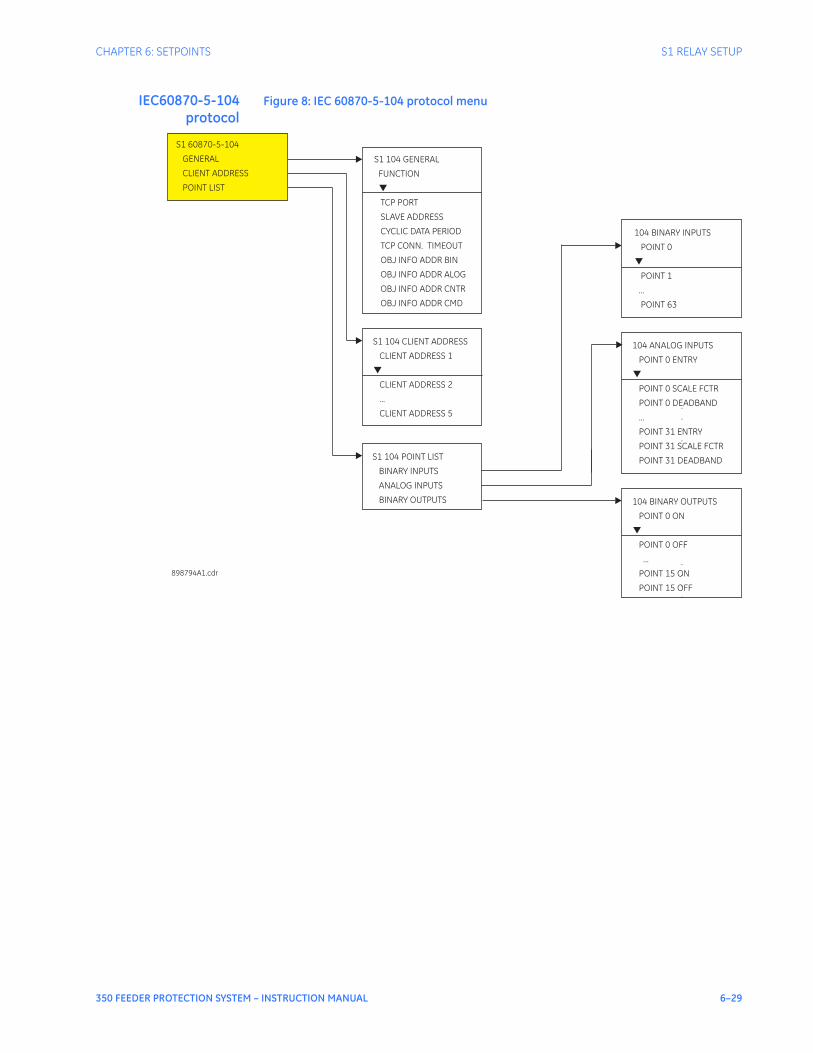
CHAPTER 6: SETPOINTS S1 RELAY SETUP
350 FEEDER PROTECTION SYSTEM – INSTRUCTION MANUAL 6–29
IEC60870-5-104protocol
Figure 8: IEC 60870-5-104 protocol menu
104 BINARY INPUTS
POINT 0
POINT 1
...
POINT 63
▼
S1 104 GENERAL
FUNCTION
CYCLIC DATA PERIOD
TCP CONN. TIMEOUT
OBJ INFO ADDR BIN
TCP PORT
SLAVE ADDRESS
▼
OBJ INFO ADDR ALOG
OBJ INFO ADDR CNTR
OBJ INFO ADDR CMD
898794A1.cdr
S1 104 POINT LIST
BINARY INPUTS
ANALOG INPUTS
BINARY OUTPUTS
S1 60870-5-104
GENERAL
CLIENT ADDRESS
POINT LIST
104 ANALOG INPUTS
POINT 0 ENTRY
POINT 0 SCALE FCTR
POINT 0 DEADBAND
...
POINT 31 ENTRY
POINT 31 SCALE FCTR
POINT 31 DEADBAND
▼
S1 104 CLIENT ADDRESS
CLIENT ADDRESS 1
CLIENT ADDRESS 2
...
CLIENT ADDRESS 5
▼
.
.
.
.
104 BINARY OUTPUTS
POINT 0 ON
POINT 0 OFF
...
POINT 15 ON
POINT 15 OFF
▼
.
.
.
.
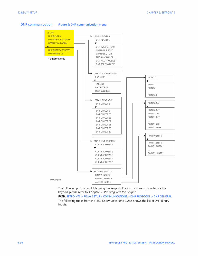
6–30 350 FEEDER PROTECTION SYSTEM – INSTRUCTION MANUAL
S1 RELAY SETUP CHAPTER 6: SETPOINTS
DNP communication Figure 9: DNP communication menu
The following path is available using the keypad. For instructions on how to use the keypad, please refer to Chapter 3 - Working with the Keypad.PATH: SETPOINTS > RELAY SETUP > COMMUNICATIONS > DNP PROTOCOL > DNP GENERALThe following table, from the 350 Communications Guide, shows the list of DNP Binary Inputs.
S1 DNP GENERAL
DNP ADDRESS
DNP TCP/UDP PORT
CHANNEL 1 PORT
CHANNEL 2 PORT
TME SYNC IIN PER.
DNP MSG FRAG SIZE
DNP TCP CONN. T/O
▼
S1 DNP
DNP GENERAL
DNP UNSOL RESPONSE*
DEFAULT VARIATION
DNP CLIENT ADDRESS*
DNP POINTS LIST
▼
898769A1.cdr
DNP CLIENT ADDRESS*
CLIENT ADDRESS 1
▼
CLIENT ADDRESS 2
CLIENT ADDRESS 3
CLIENT ADDRESS 4
CLIENT ADDRESS 5
POINT 0
...
▼
POINT 1
POINT 2
POINT 63
S1 DNP POINTS LIST
BINARY INPUTS
BINARY OUTPUTS
ANALOG INPUTS
POINT 0 ENTRY
...
POINT 1
POINT 2
POINT 31
▼
ENTRY
ENTRY
ENTRY
POINT 0 ON
...
POINT 0 OFF
POINT 1 ON
POINT 1 OFF
POINT 15 ON
POINT 15 OFF
▼
DEFAULT VARIATION
DNP OBJECT 1
▼
DNP OBJECT 2
DNP OBJECT 20
DNP OBJECT 21
DNP OBJECT 22
DNP OBJECT 23
DNP OBJECT 30
DNP OBJECT 32
DNP UNSOL RESPONSE*
FUNCTION
▼
TIMEOUT
MAX RETRIES
DEST ADDRESS
* Ethernet only
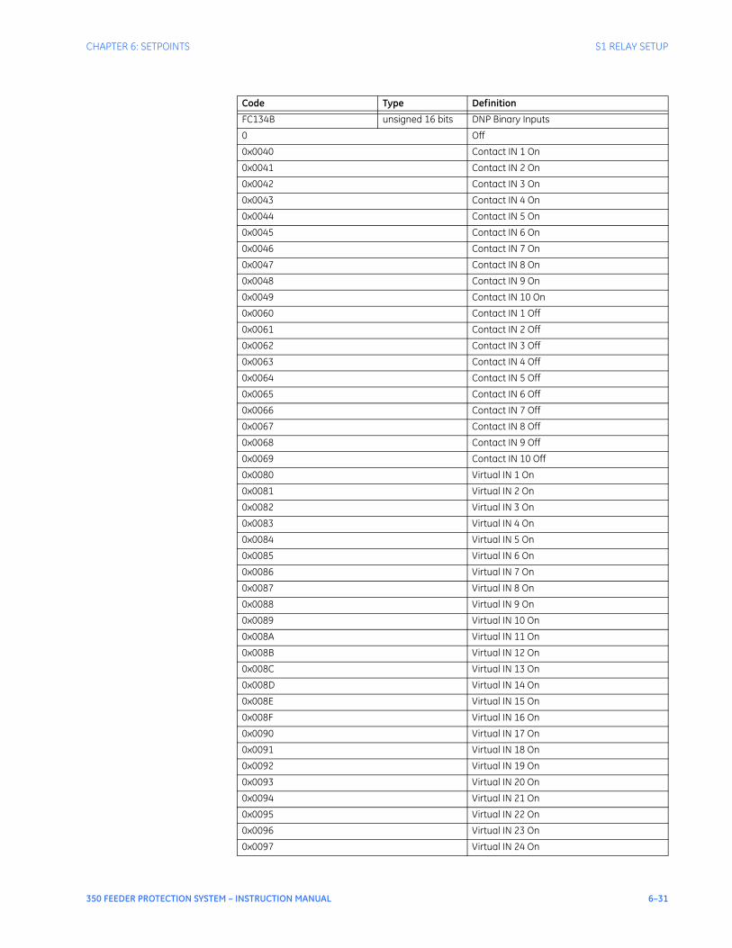
CHAPTER 6: SETPOINTS S1 RELAY SETUP
350 FEEDER PROTECTION SYSTEM – INSTRUCTION MANUAL 6–31
Code Type Definition
FC134B unsigned 16 bits DNP Binary Inputs
0 Off
0x0040 Contact IN 1 On
0x0041 Contact IN 2 On
0x0042 Contact IN 3 On
0x0043 Contact IN 4 On
0x0044 Contact IN 5 On
0x0045 Contact IN 6 On
0x0046 Contact IN 7 On
0x0047 Contact IN 8 On
0x0048 Contact IN 9 On
0x0049 Contact IN 10 On
0x0060 Contact IN 1 Off
0x0061 Contact IN 2 Off
0x0062 Contact IN 3 Off
0x0063 Contact IN 4 Off
0x0064 Contact IN 5 Off
0x0065 Contact IN 6 Off
0x0066 Contact IN 7 Off
0x0067 Contact IN 8 Off
0x0068 Contact IN 9 Off
0x0069 Contact IN 10 Off
0x0080 Virtual IN 1 On
0x0081 Virtual IN 2 On
0x0082 Virtual IN 3 On
0x0083 Virtual IN 4 On
0x0084 Virtual IN 5 On
0x0085 Virtual IN 6 On
0x0086 Virtual IN 7 On
0x0087 Virtual IN 8 On
0x0088 Virtual IN 9 On
0x0089 Virtual IN 10 On
0x008A Virtual IN 11 On
0x008B Virtual IN 12 On
0x008C Virtual IN 13 On
0x008D Virtual IN 14 On
0x008E Virtual IN 15 On
0x008F Virtual IN 16 On
0x0090 Virtual IN 17 On
0x0091 Virtual IN 18 On
0x0092 Virtual IN 19 On
0x0093 Virtual IN 20 On
0x0094 Virtual IN 21 On
0x0095 Virtual IN 22 On
0x0096 Virtual IN 23 On
0x0097 Virtual IN 24 On

6–32 350 FEEDER PROTECTION SYSTEM – INSTRUCTION MANUAL
S1 RELAY SETUP CHAPTER 6: SETPOINTS
0x0098 Virtual IN 25 On
0x0099 Virtual IN 26 On
0x009A Virtual IN 27 On
0x009B Virtual IN 28 On
0x009C Virtual IN 29 On
0x009D Virtual IN 30 On
0x009E Virtual IN 31 On
0x009F Virtual IN 32 On
0x00A0 Virtual IN 1 Off
0x00A1 Virtual IN 2 Off
0x00A2 Virtual IN 3 Off
0x00A3 Virtual IN 4 Off
0x00A4 Virtual IN 5 Off
0x00A5 Virtual IN 6 Off
0x00A6 Virtual IN 7 Off
0x00A7 Virtual IN 8 Off
0x00A8 Virtual IN 9 Off
0x00A9 Virtual IN 10 Off
0x00AA Virtual IN 11 Off
0x00AB Virtual IN 12 Off
0x00AC Virtual IN 13 Off
0x00AD Virtual IN 14 Off
0x00AE Virtual IN 15 Off
0x00AF Virtual IN 16 Off
0x00B0 Virtual IN 17 Off
0x00B1 Virtual IN 18 Off
0x00B2 Virtual IN 19 Off
0x00B3 Virtual IN 20 Off
0x00B5 Virtual IN 22 Off
0x00B6 Virtual IN 23 Off
0x00B7 Virtual IN 24 Off
0x00B8 Virtual IN 25 Off
0x00B9 Virtual IN 26 Off
0x00BA Virtual IN 27 Off
0x00BB Virtual IN 28 Off
0x00BC Virtual IN 29 Off
0x00BD Virtual IN 30 Off
0x00BE Virtual IN 31 Off
0x00BF Virtual IN 32 Off
0x01C0 Remote IN 1 On
0x01C1 Remote IN 2 On
0x01C2 Remote IN 3 On
0x01C3 Remote IN 4 On
0x01C4 Remote IN 5 On
0x01C5 Remote IN 6 On
0x01C6 Remote IN 7 On
0x01C7 Remote IN 8 On
Code Type Definition

CHAPTER 6: SETPOINTS S1 RELAY SETUP
350 FEEDER PROTECTION SYSTEM – INSTRUCTION MANUAL 6–33
0x01C8 Remote IN 9 On
0x01C9 Remote IN 10 On
0x01CA Remote IN 11 On
0x01CB Remote IN 12 On
0x01CC Remote IN 13 On
0x01CD Remote IN 14 On
0x01CE Remote IN 15 On
0x01CF Remote IN 16 On
0x01D0 Remote IN 17 On
0x01D1 Remote IN 18 On
0x01D2 Remote IN 19 On
0x01D3 Remote IN 20 On
0x01D4 Remote IN 21 On
0x01D5 Remote IN 22 On
0x01D6 Remote IN 23 On
0x01D7 Remote IN 24 On
0x01D8 Remote IN 25 On
0x01D9 Remote IN 26 On
0x01DA Remote IN 27 On
0x01DB Remote IN 28 On
0x01DC Remote IN 29 On
0x01DD Remote IN 30 On
0x01DE Remote IN 31 On
0x01DF Remote IN 32 On
0x01E0 Remote IN 1 Off
0x01E1 Remote IN 2 Off
0x01E2 Remote IN 3 Off
0x01E3 Remote IN 4 Off
0x01E4 Remote IN 5 Off
0x01E5 Remote IN 6 Off
0x01E6 Remote IN 7 Off
0x01E7 Remote IN 8 Off
0x01E8 Remote IN 9 Off
0x01E9 Remote IN 10 Off
0x01EA Remote IN 11 Off
0x01EB Remote IN 12 Off
0x01EC Remote IN 13 Off
0x01ED Remote IN 14 Off
0x01EE Remote IN 15 Off
0x01EF Remote IN 16 Off
0x01F0 Remote IN 17 Off
0x01F1 Remote IN 18 Off
0x01F2 Remote IN 19 Off
0x01F3 Remote IN 20 Off
0x01F4 Remote IN 21 Off
0x01F5 Remote IN 22 Off
0x01F6 Remote IN 23 Off
Code Type Definition

6–34 350 FEEDER PROTECTION SYSTEM – INSTRUCTION MANUAL
S1 RELAY SETUP CHAPTER 6: SETPOINTS
0x01F7 Remote IN 24 Off
0x01F8 Remote IN 25 Off
0x01F9 Remote IN 26 Off
0x01FA Remote IN 27 Off
0x01FB Remote IN 28 Off
0x01FC Remote IN 29 Off
0x01FD Remote IN 30 Off
0x01FE Remote IN 31 Off
0x01FF Remote IN 32 Off
0x8002 Any Trip
0x8042 Therm O/L Trip OP
0x8044 Therm O/L Trip DPO
0x804A Therm PhA Trip OP
0x804C Therm PhA Trip DPO
0x8052 Therm PhB Trip OP
0x8054 Therm PhB Trip DPO
0x8062 Therm PhC Trip OP
0x8064 Therm PhC Trip DPO
0x84C1 LE 1 Trip PKP
0x84C2 LE 1 Trip OP
0x84C4 LE 1 Trip DPO
0x8501 LE 2 Trip PKP
0x8502 LE 2 Trip OP
0x8504 LE 2 Trip DPO
0x8541 LE 3 Trip PKP
0x8542 LE 3 Trip OP
0x8544 LE 3 Trip DPO
0x8581 LE 4 Trip PKP
0x8582 LE 4 Trip OP
0x8584 LE 4 Trip DPO
0x85C1 LE 5 Trip PKP
0x85C2 LE 5 Trip OP
0x85C4 LE 5 Trip DPO
0x8601 LE 6 Trip PKP
0x8602 LE 6 Trip OP
0x8604 LE 6 Trip DPO
0x8641 LE 7 Trip PKP
0x8642 LE 7 Trip OP
0x8644 LE 7 Trip DPO
0x8681 LE 8 Trip PKP
0x8682 LE 8 Trip OP
0x8684 LE 8 Trip DPO
0x89C2 Self Test OP
0x9001 Ph IOC1 Trip PKP
0x9002 Ph IOC1 Trip OP
0x9004 Ph IOC1 Trip DPO
0x9009 Ph A IOC1 Trip PKP
Code Type Definition

CHAPTER 6: SETPOINTS S1 RELAY SETUP
350 FEEDER PROTECTION SYSTEM – INSTRUCTION MANUAL 6–35
0x900A Ph A IOC1 Trip OP
0x900C Ph A IOC1 Trip DPO
0x9011 Ph B IOC1 Trip PKP
0x9012 Ph B IOC1 Trip OP
0x9014 Ph B IOC1 Trip DPO
0x9021 Ph C IOC1 Trip PKP
0x9022 Ph C IOC1 Trip OP
0x9024 Ph C IOC1 Trip DPO
0x9041 Ntrl IOC1 Trip PKP
0x9042 Ntrl IOC1 Trip OP
0x9044 Ntrl IOC1 Trip DPO
0x9081 Gnd IOC1 Trip PKP
0x9082 Gnd IOC1 Trip OP
0x9084 Gnd IOC1 Trip DPO
0x90C1 Ph TOC1 Trip PKP
0x90C2 Ph TOC1 Trip OP
0x90C4 Ph TOC1 Trip DPO
0x90C9 Ph A TOC1 Trip PKP
0x90CA Ph A TOC1 Trip OP
0x90CC Ph A TOC1 Trip DPO
0x90D1 Ph B TOC1 Trip PKP
0x90D2 Ph B TOC1 Trip OP
0x90D4 Ph B TOC1 Trip DPO
0x90E1 Ph C TOC1 Trip PKP
0x90E2 Ph C TOC1 Trip OP
0x90E4 Ph C TOC1 Trip DPO
0x9101 Ntrl TOC1 Trip PKP
0x9102 Ntrl TOC1 Trip OP
0x9104 Ntrl TOC1 Trip DPO
0x9141 Gnd TOC1 Trip PKP
0x9142 Gnd TOC1 Trip OP
0x9144 Gnd TOC1 Trip DPO
0x9181 Ph IOC2 Trip PKP
0x9182 Ph IOC2 Trip OP
0x9184 Ph IOC2 Trip DPO
0x9189 Ph A IOC2 Trip PKP
0x918A Ph A IOC2 Trip OP
0x918C Ph A IOC2 Trip DPO
0x9191 Ph B IOC2 Trip PKP
0x9192 Ph B IOC2 Trip OP
0x9194 Ph B IOC2 Trip DPO
0x91A1 Ph C IOC2 Trip PKP
0x91A2 Ph C IOC2 Trip OP
0x91A4 Ph C IOC2 Trip DPO
0x91C1 Ntrl IOC2 Trip PKP
0x91C2 Ntrl IOC2 Trip OP
0x91C4 Ntrl IOC2 Trip DPO
Code Type Definition

6–36 350 FEEDER PROTECTION SYSTEM – INSTRUCTION MANUAL
S1 RELAY SETUP CHAPTER 6: SETPOINTS
0x9201 Gnd IOC2 Trip PKP
0x9202 Gnd IOC2 Trip OP
0x9204 Gnd IOC2 Trip DPO
0x9301 SGnd TOC1 Trip PKP
0x9302 SGnd TOC1 Trip OP
0x9304 SGnd TOC1 Trip DPO
0x93C1 NegSeq OV Trp PKP
0x93C2 NegSeq OV Trp OP
0x93C4 NegSeq OV Trp DPO
0x9401 Ntrl OV Trip PKP
0x9402 Ntrl OV Trp OP
0x9404 Ntrl OV Trip DPO
0x9441 Ph OV1 Trip PKP
0x9442 Ph OV1 Trip OP
0x9444 Ph OV1 Trip DPO
0x9449 Ph A OV1 Trip PKP
0x944A Ph A OV1 Trip OP
0x944C Ph A OV1 Trip DPO
0x9451 Ph B OV1 Trip PKP
0x9452 Ph B OV1 Trip OP
0x9454 Ph B OV1 Trip DPO
0x9461 Ph C OV1 Trip PKP
0x9462 Ph C OV1 Trip OP
0x9464 Ph C OV1 Trip DPO
0x9481 Ph UV1 Trip PKP
0x9482 Ph UV1 Trip OP
0x9484 Ph UV1 Trip DPO
0x9489 Ph A UV1 Trip PKP
0x948A Ph A UV1 Trip OP
0x948C Ph A UV1 Trip DPO
0x9491 Ph B UV1 Trip PKP
0x9492 Ph B UV1 Trip OP
0x9494 Ph B UV1 Trip DPO
0x94A1 Ph C UV1 Trip PKP
0x94A2 Ph C UV1 Trip OP
0x94A4 Ph C UV1 Trip DPO
0x94C1 Aux OV Trip PKP
0x94C2 Aux OV Trip OP
0x94C4 Aux OV Trip DPO
0x9501 Aux UV Trip PKP
0x9502 Aux UV Trip OP
0x9504 Aux UV Trip DPO
0x9541 UndrFreq1 Trip PKP
0x9542 UndrFreq1 Trip OP
0x9544 UndrFreq1 Trip DPO
0x9581 UndrFreq2 Trip PKP
0x9582 UndrFreq2 Trip OP
Code Type Definition

CHAPTER 6: SETPOINTS S1 RELAY SETUP
350 FEEDER PROTECTION SYSTEM – INSTRUCTION MANUAL 6–37
0x9584 UndrFreq2 Trip DPO
0x95C1 OverFreq1 Trip PKP
0x95C2 OverFreq1 Trip OP
0x95C4 OverFreq1 Trip DPO
0x9601 OverFreq2 Trip PKP
0x9602 OverFreq2 Trip OP
0x9604 OverFreq2 Trip DPO
0x9641 SGnd IOC1 Trip PKP
0x9642 SGnd IOC1 Trip OP
0x9644 SGnd IOC1 Trip DPO
0x9681 SGnd IOC2 Trip PKP
0x9682 SGnd IOC2 Trip OP
0x9684 SGnd IOC2 Trip DPO
0x96C1 NegSeq IOC Trp PKP
0x96C2 NegSeq IOC Trp OP
0x96C4 NegSeq IOC Trp DPO
0x98D2 Ph B UV2 Trip OP
0x9C01 LE 9 Trip PKP
0x9C02 LE 9 Trip OP
0x9C04 LE 9 Trip DPO
0x9C41 LE 10 Trip PKP
0x9C42 LE 10 Trip OP
0x9C44 LE 10 Trip DPO
0x9C81 LE 11 Trip PKP
0x9C82 LE 11 Trip OP
0x9C84 LE 11 Trip DPO
0x9CC1 LE 12 Trip PKP
0x9CC2 LE 12 Trip OP
0x9CC4 LE 12 Trip DPO
0x9D01 LE 13 Trip PKP
0x9D02 LE 13 Trip OP
0x9D04 LE 13 Trip DPO
0x9D41 LE 14 Trip PKP
0x9D42 LE 14 Trip OP
0x9D44 LE 14 Trip DPO
0x9D81 LE 15 Trip PKP
0x9D82 LE 15 Trip OP
0x9D84 LE 15 Trip DPO
0x9DC1 LE 16 Trip PKP
0x9DC2 LE 16 Trip OP
0x9DC4 LE 16 Trip DPO
0xA002 Any Alarm
0xA042 Therm Lvl Alrm OP
0xA044 Therm Lvl Alrm DPO
0xA04A Therm PhA Alrm OP
0xA04C Therm PhA Alrm DPO
0xA052 Therm PhB Alrm OP
Code Type Definition

6–38 350 FEEDER PROTECTION SYSTEM – INSTRUCTION MANUAL
S1 RELAY SETUP CHAPTER 6: SETPOINTS
0xA054 Therm PhB Alrm DPO
0xA062 Therm PhC Alrm OP
0xA064 Therm PhC Alrm DPO
0xA482 Relay Not Ready
0xA4C1 LE 1 Alarm PKP
0xA4C2 LE 1 Alarm OP
0xA4C4 LE 1 Alarm DPO
0xA501 LE 2 Alarm PKP
0xA502 LE 2 Alarm OP
0xA504 LE 2 Alarm DPO
0xA541 LE 3 Alarm PKP
0xA542 LE 3 Alarm OP
0xA544 LE 3 Alarm DPO
0xA581 LE 4 Alarm PKP
0xA582 LE 4 Alarm OP
0xA584 LE 4 Alarm DPO
0xA5C1 LE 5 Alarm PKP
0xA5C2 LE 5 Alarm OP
0xA5C4 LE 5 Alarm DPO
0xA601 LE 6 Alarm PKP
0xA602 LE 6 Alarm OP
0xA604 LE 6 Alarm DPO
0xA641 LE 7 Alarm PKP
0xA642 LE 7 Alarm OP
0xA644 LE 7 Alarm DPO
0xA681 LE 8 Alarm PKP
0xA682 LE 8 Alarm OP
0xA684 LE 8 Alarm DPO
0xABC1 HI Amb Temp PKP
0xABC2 HI Amb Temp OP
0xABC4 HI Amb Temp DPO
0xAC01 LO Amb Temp PKP
0xAC02 LO Amb Temp OP
0xAC04 LO Amb Temp DPO
0xAC42 Self Test Alarm OP
0xACC2 BKRTrpCntrAlrm OP
0xAD02 R1 CoilMonAlrm OP
0xAD42 R2 CoilMonAlrm OP
0xAD81 BKR1 Fail Alrm PKP
0xAD82 BKR1 Fail Alrm OP
0xAD84 BKR1 Fail Alrm DPO
0xADC2 BKR1 Stat Fail OP
0xAE41 CLP Alarm PKP
0xAE42 CLP Alarm OP
0xB001 Ph IOC1 Alarm PKP
0xB002 Ph IOC1 Alarm OP
0xB004 Ph IOC1 Alarm DPO
Code Type Definition

CHAPTER 6: SETPOINTS S1 RELAY SETUP
350 FEEDER PROTECTION SYSTEM – INSTRUCTION MANUAL 6–39
0xB009 Ph A IOC1 Alrm PKP
0xB00A Ph A IOC1 Alrm OP
0xB00C Ph A IOC1 Alrm DPO
0xB011 Ph B IOC1 Alrm PKP
0xB012 Ph B IOC1 Alrm OP
0xB014 Ph B IOC1 Alrm DPO
0xB021 Ph C IOC1 Alrm PKP
0xB022 Ph C IOC1 Alrm OP
0xB024 Ph C IOC1 Alrm DPO
0xB041 Ntrl IOC1 Alrm PKP
0xB042 Ntrl IOC1 Alrm OP
0xB044 Ntrl IOC1 Alrm DPO
0xB081 Gnd IOC1 Alarm PKP
0xB082 Gnd IOC1 Alarm OP
0xB084 Gnd IOC1 Alarm DPO
0xB0C1 Ph TOC1 Alarm PKP
0xB0C2 Ph TOC1 Alarm OP
0xB0C4 Ph TOC1 Alarm DPO
0xB0C9 Ph A TOC1 Alrm PKP
0xB0CA Ph A TOC1 Alrm OP
0xB0CC Ph A TOC1 Alrm DPO
0xB0D1 Ph B TOC1 Alrm PKP
0xB0D2 Ph B TOC1 Alrm OP
0xB0D4 Ph B TOC1 Alrm DPO
0xB0E1 Ph C TOC1 Alrm PKP
0xB0E2 Ph C TOC1 Alrm OP
0xB0E4 Ph C TOC1 Alrm DPO
0xB101 Ntrl TOC1 Alrm PKP
0xB102 Ntrl TOC1 Alrm OP
0xB104 Ntrl TOC1 Alrm DPO
0xB141 Gnd TOC1 Alarm PKP
0xB142 Gnd TOC1 Alarm OP
0xB144 Gnd TOC1 Alarm DPO
0xB181 Ph IOC2 Alarm PKP
0xB182 Ph IOC2 Alarm OP
0xB184 Ph IOC2 Alarm DPO
0xB189 Ph A IOC2 Alrm PKP
0xB18A Ph A IOC2 Alrm OP
0xB18C Ph A IOC2 Alrm DPO
0xB191 Ph B IOC2 Alrm PKP
0xB192 Ph B IOC2 Alrm OP
0xB194 Ph B IOC2 Alrm DPO
0xB1A1 Ph C IOC2 Alrm PKP
0xB1A2 Ph C IOC2 Alrm OP
0xB1A4 Ph C IOC2 Alrm DPO
0xB1C1 Ntrl IOC2 Alrm PKP
0xB1C2 Ntrl IOC2 Alrm OP
Code Type Definition

6–40 350 FEEDER PROTECTION SYSTEM – INSTRUCTION MANUAL
S1 RELAY SETUP CHAPTER 6: SETPOINTS
0xB1C4 Ntrl IOC2 Alrm DPO
0xB201 Gnd IOC2 Alarm PKP
0xB202 Gnd IOC2 Alarm OP
0xB204 Gnd IOC2 Alarm DPO
0xB301 SGnd TOC1 Alrm PKP
0xB302 SGnd TOC1 Alrm OP
0xB304 SGnd TOC1 Alrm DPO
0xB342 NtrlDir RevAlm OP
0xB344 NtrlDir RevAlm DPO
0xB382 GndDir RevAlm OP
0xB384 GndDir RevAlm DPO
0xB3C1 NegSeq OV Alrm PKP
0xB3C2 NegSeq OV Alrm OP
0xB3C4 NegSeq OV Alrm DPO
0xB401 Ntrl OV Alrm PKP
0xB402 Ntrl OV Alrm OP
0xB404 Ntrl OV Alrm DPO
0xB441 Ph OV1 Alarm PKP
0xB442 Ph OV1 Alarm OP
0xB444 Ph OV1 Alarm DPO
0xB449 Ph A OV1 Alarm PKP
0xB44A Ph A OV1 Alarm OP
0xB44C Ph A OV1 Alarm DPO
0xB451 Ph B OV1 Alarm PKP
0xB452 Ph B OV1 Alarm OP
0xB454 Ph B OV1 Alarm DPO
0xB461 Ph C OV1 Alarm PKP
0xB462 Ph C OV1 Alarm OP
0xB464 Ph C OV1 Alarm DPO
0xB481 Ph UV1 Alarm PKP
0xB482 Ph UV1 Alarm OP
0xB484 Ph UV1 Alarm DPO
0xB489 Ph A UV1 Alarm PKP
0xB48A Ph A UV1 Alarm OP
0xB48C Ph A UV1 Alarm DPO
0xB491 Ph B UV1 Alarm PKP
0xB492 Ph B UV1 Alarm OP
0xB494 Ph B UV1 Alarm DPO
0xB4A1 Ph C UV1 Alarm PKP
0xB4A2 Ph C UV1 Alarm OP
0xB4A4 Ph C UV1 Alarm DPO
0xB4C1 Aux OV Alarm PKP
0xB4C2 Aux OV Alarm OP
0xB4C4 Aux OV Alarm DPO
0xB501 Aux UV Alarm PKP
0xB502 Aux UV Alarm OP
0xB504 Aux UV Alarm DPO
Code Type Definition

CHAPTER 6: SETPOINTS S1 RELAY SETUP
350 FEEDER PROTECTION SYSTEM – INSTRUCTION MANUAL 6–41
0xB541 UndrFreq1 Alrm PKP
0xB542 UndrFreq1 Alrm OP
0xB544 UndrFreq1 Alrm DPO
0xB581 UndrFreq2 Alrm PKP
0xB582 UndrFreq2 Alrm OP
0xB584 UndrFreq2 Alrm DPO
0xB5C1 OverFreq1 Alrm PKP
0xB5C2 OverFreq1 Alrm OP
0xB5C4 OverFreq1 Alrm DPO
0xB601 OverFreq2 Alrm PKP
0xB602 OverFreq2 Alrm OP
0xB604 OverFreq2 Alrm DPO
0xB641 SGnd IOC1 Alrm PKP
0xB642 SGnd IOC1 Alrm OP
0xB644 SGnd IOC1 Alrm DPO
0xB681 SGnd IOC2 Alrm PKP
0xB682 SGnd IOC2 Alrm OP
0xB684 SGnd IOC2 Alrm DPO
0xB6C1 NSeq IOC Alrm PKP
0xB6C2 NSeq IOC Alrm OP
0xB6C4 NSeq IOC Alrm DPO
0xBC01 LE 9 Alarm PKP
0xBC02 LE 9 Alarm OP
0xBC04 LE 9 Alarm DPO
0xBC41 LE 10 Alarm PKP
0xBC42 LE 10 Alarm OP
0xBC44 LE 10 Alarm DPO
0xBC81 LE 11 Alarm PKP
0xBC82 LE 11 Alarm OP
0xBC84 LE 11 Alarm DPO
0xBCC1 LE 12 Alarm PKP
0xBCC2 LE 12 Alarm OP
0xBCC4 LE 12 Alarm DPO
0xBD01 LE 13 Alarm PKP
0xBD02 LE 13 Alarm OP
0xBD04 LE 13 Alarm DPO
0xBD41 LE 14 Alarm PKP
0xBD42 LE 14 Alarm OP
0xBD44 LE 14 Alarm DPO
0xBD81 LE 15 Alarm PKP
0xBD82 LE 15 Alarm OP
0xBD84 LE 15 Alarm DPO
0xBDC1 LE 16 Alarm PKP
0xBDC2 LE 16 Alarm OP
0xBDC4 LE 16 Alarm DPO
0xC042 Output Relay 3 On
0xC082 Output Relay 4 On
Code Type Definition

6–42 350 FEEDER PROTECTION SYSTEM – INSTRUCTION MANUAL
S1 RELAY SETUP CHAPTER 6: SETPOINTS
0xC0C2 Output Relay 5 On
0xC102 Output Relay 6 On
0xC142 Self-Test Rly 7 On
0xC182 Output Relay 1 On
0xC1C2 Output Relay 2 On
0xC202 BKR Connected
0xC4C1 LE 1 PKP
0xC4C2 LE 1 OP
0xC4C4 LE 1 DPO
0xC501 LE 2 PKP
0xC502 LE 2 OP
0xC504 LE 2 DPO
0xC541 LE 3 PKP
0xC542 LE 3 OP
0xC544 LE 3 DPO
0xC581 LE 4 PKP
0xC582 LE 4 OP
0xC584 LE 4 DPO
0xC5C1 LE 5 PKP
0xC5C2 LE 5 OP
0xC5C4 LE 5 DPO
0xC601 LE 6 PKP
0xC602 LE 6 OP
0xC604 LE 6 DPO
0xC641 LE 7 PKP
0xC642 LE 7 OP
0xC644 LE 7 DPO
0xC681 LE 8 PKP
0xC682 LE 8 OP
0xC684 LE 8 DPO
0xC882 Setpoint Group2 On
0xC902 Open Breaker
0xC942 Close Breaker
0xC982 Maint. Req. OP
0xCA02 52a Contact OP
0xCA42 52b Contact OP
0xCA44 52b Contact DPO
0xCA82 Reset OK
0xCB01 AR Close PKP
0xCB02 AR Close
0xCB04 AR Close DPO
0xCB42 AR N/Ready
0xCB81 AR In Progress PKP
0xCB82 AR In Progress
0xCB84 AR In Progress DPO
0xCBC1 AR Disabled PKP
0xCBC2 AR Disabled
Code Type Definition

CHAPTER 6: SETPOINTS S1 RELAY SETUP
350 FEEDER PROTECTION SYSTEM – INSTRUCTION MANUAL 6–43
0xCBC4 AR Disabled DPO
0xCC02 AR Ext. Init
0xCC41 AR Ready PKP
0xCC42 AR Ready
0xCC44 AR Ready DPO
0xCCC2 BKR Stat Open
0xCD02 BKR Stat Clsd
0xCD42 Setpoint Group1 On
0xCE41 CLP PKP
0xCE42 CLP Op
0xCE44 CLP DPO
0xD342 Ntrl Dir Rev OP
0xD344 Ntrl Dir Rev DPO
0xD382 Gnd Dir Rev OP
0xD384 Gnd Dir Rev DPO
0xDC01 LE 9 PKP
0xDC02 LE 9 OP
0xDC04 LE 9 DPO
0xDC41 LE 10 PKP
0xDC42 LE 10 OP
0xDC44 LE 10 DPO
0xDC81 LE 11 PKP
0xDC82 LE 11 OP
0xDC84 LE 11 DPO
0xDCC1 LE 12 PKP
0xDCC2 LE 12 OP
0xDCC4 LE 12 DPO
0xDD01 LE 13 PKP
0xDD02 LE 13 OP
0xDD04 LE 13 DPO
0xDD41 LE 14 PKP
0xDD42 LE 14 OP
0xDD44 LE 14 DPO
0xDD81 LE 15 PKP
0xDD82 LE 15 OP
0xDD84 LE 15 DPO
0xDDC1 LE 16 PKP
0xDDC2 LE 16 OP
0xDDC4 LE 16 DPO
0xE002 Any Block
0xE042 Therm O/L Blck
0xE182 Output Relay 1 BLK
0xE1C2 Output Relay 2 BLK
0xE882 Group Change Blk
0xEB02 AR Block
0xEE82 CLP Ph IOC1 BLK
0xEEC2 CLP Ph IOC2 BLK
Code Type Definition

6–44 350 FEEDER PROTECTION SYSTEM – INSTRUCTION MANUAL
S1 RELAY SETUP CHAPTER 6: SETPOINTS
IEC 61850 GOOSEcommunications
The 350 firmware supports IEC61850 GOOSE communications on the optional communications daughter board.Portions of the IEC61850 standard not pertaining to GOOSE, are not implemented in the 350 relay.The 350 relay does not support• an IEC61850 MMS server• the mapping of analogue values to data points in data sets in either the transmit or
receive direction• a file system to maintain SCL, ICD or CID files, for IEC61850 GOOSE. As such the
implementation stores GOOSE configuration using MODBUS set points.Configuration of transmission and reception settings for the GOOSE feature are performed using EnerVista SR3 Setup Software.The 350 firmware accepts GOOSE messages from UR, F650 and UR Plus. The interoperability with other manufacturers will be guaranteed in almost all cases, by implementing the reception side with nested structures (one level of nesting) and all the standard data types.
0xEF02 CLPNtrlIOC1 BLK
0xEF42 CLPNtrlIOC2 BLK
0xEF82 CLP GndIOC1 BLK
0xEFC2 CLP GndIOC2 BLK
0xF002 Ph IOC1 Block
0xF042 Ntrl IOC1 Block
0xF082 Gnd IOC1 Block
0xF0C2 Ph TOC1 Block
0xF102 Ntrl TOC1 Block
0xF142 Gnd TOC1 Block
0xF182 Ph IOC2 Block
0xF1C2 Ntrl IOC2 Block
0xF202 Gnd IOC2 Block
0xF302 SGnd TOC1 Block
0xF342 Ntrl Dir Block
0xF382 Gnd Dir Block
0xF3C2 NegSeq OV Block
0xF402 Ntrl OV Block
0xF442 Ph OV1 Block
0xF482 Ph UV1 Block
0xF4C2 Aux OV Block
0xF502 Aux UV Block
0xF542 UndrFreq1 Block
0xF582 UndrFreq2 Block
0xF5C2 OverFreq1 Block
0xF602 OverFreq2 Block
0xF642 SGnd IOC1 Block
0xF682 SGnd IOC2 Block
0xF6C2 NSeq IOC Block
Code Type Definition
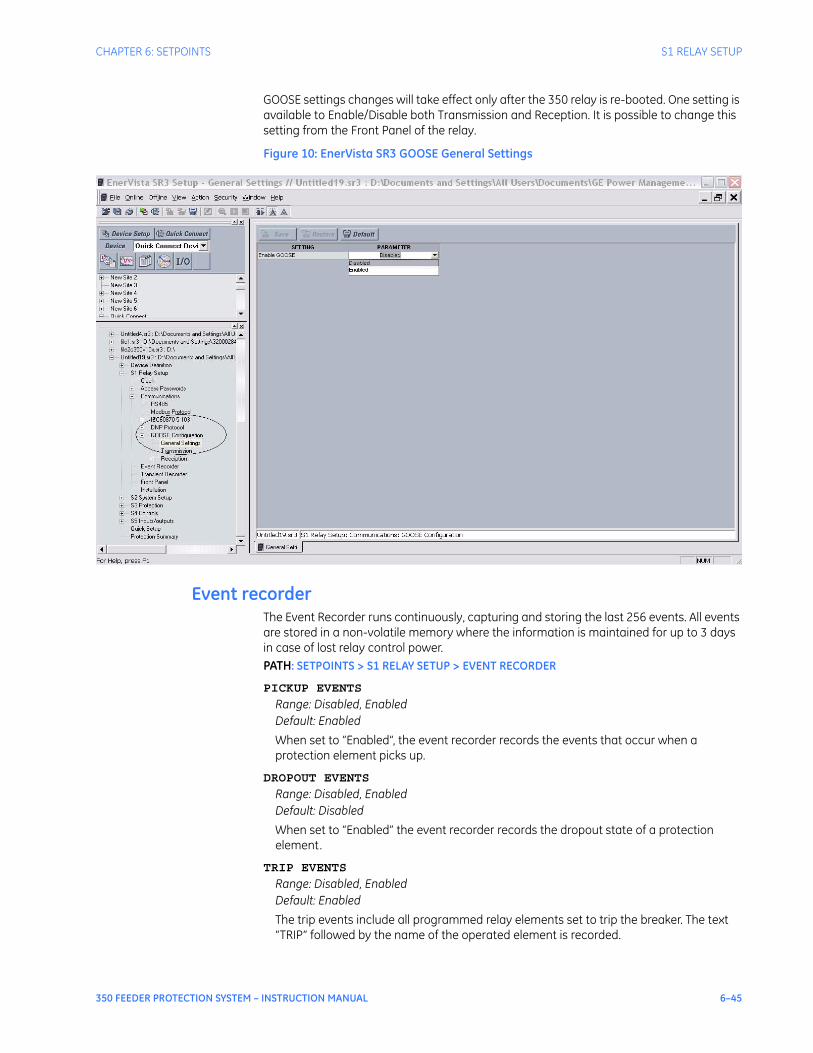
CHAPTER 6: SETPOINTS S1 RELAY SETUP
350 FEEDER PROTECTION SYSTEM – INSTRUCTION MANUAL 6–45
GOOSE settings changes will take effect only after the 350 relay is re-booted. One setting is available to Enable/Disable both Transmission and Reception. It is possible to change this setting from the Front Panel of the relay.
Figure 10: EnerVista SR3 GOOSE General Settings
Event recorderThe Event Recorder runs continuously, capturing and storing the last 256 events. All events are stored in a non-volatile memory where the information is maintained for up to 3 days in case of lost relay control power. PATH: SETPOINTS > S1 RELAY SETUP > EVENT RECORDER
PICKUP EVENTS
Range: Disabled, EnabledDefault: Enabled
When set to “Enabled”, the event recorder records the events that occur when a protection element picks up.
DROPOUT EVENTS
Range: Disabled, EnabledDefault: Disabled
When set to “Enabled” the event recorder records the dropout state of a protection element.
TRIP EVENTS
Range: Disabled, EnabledDefault: Enabled
The trip events include all programmed relay elements set to trip the breaker. The text “TRIP” followed by the name of the operated element is recorded.

6–46 350 FEEDER PROTECTION SYSTEM – INSTRUCTION MANUAL
S1 RELAY SETUP CHAPTER 6: SETPOINTS
ALARM EVENTS
Range: Disabled, EnabledDefault: Enabled
These events include the elements programmed as an “ALARM” or “LATCHED ALARM” function, which detect power system conditions considered as an alarm.
CONTROL EVENTS
Range: Disabled, EnabledDefault: Enabled
If set to “Enabled”, the event recorder records events caused by the performance of the programmed control elements.
CONTACT INPUTS
Range: Disabled, EnabledDefault: Enabled
When set to “Enabled”, the event recorder will record the event, when a contact input changes its state.
LOGIC ELEMENT
Range: Disabled, EnabledDefault: Enabled
When set to “Enabled”, the event recorder records the events, which occur upon state change of any programmed remote input.
VIRTUAL INPUTS
Range: Disabled, EnabledDefault: Enabled
When set to “Enabled”, the event recorder records the events, which occur upon state changes of any logic element.
REMOTE INPUTS
Range: Disabled, EnabledDefault: Enabled
When set to “Enabled”, the event recorder records the events, which occur upon state change of any programmed remote input.
Transient recorderThe Transient Recorder contains waveforms captured at the same sampling rate as the other relay data at the point of trigger. By default, data is captured for the analog current and voltage inputs - Ia, Ib, Ic, Ig, Va, Vb, Vc, and Vx when relay is ordered with CTs and VTs, or only analog current inputs Ia, Ib, Ic, and Ig when relay is ordered without VTs. Triggering of the transient recorder occurs, when an event is detected, causing a pickup, trip, dropout, or alarm, any one of which has been "Enabled" to activate the trigger. The transient recorder trigger may also be activated when any of the selected trigger inputs 1 to 3 is detected as having “On” status. The following path is available using the keypad. For instructions on how to use the keypad, please refer to Chapter 3 - Working with the Keypad.PATH: SETPOINTS > S1 RELAY SETUP > TRANSIENT RECDR
BUFFER SETUP
Range: 1 x 192, 3 x 64, 6 x 32Default: 3 x 64
Each selection from the range is expressed by two numbers; the first identifies the number of records, whereas the second stands for the number of cycles per record.

CHAPTER 6: SETPOINTS S1 RELAY SETUP
350 FEEDER PROTECTION SYSTEM – INSTRUCTION MANUAL 6–47
TRIGGER MODE
Range: Overwrite, ProtectedDefault: Overwrite
When the “Overwrite” setting is selected, the new records overwrite the old ones, meaning the relay will always keep the newest records. In “Protected” mode, the relay will keep the number of records corresponding to the selected number, only without overwriting.
TRIGGER POSITION
Range: 0 to 100% in steps of 1%Default: 0%
This setting indicates the location of the trigger with respect to the selected length of record. For example at 20% selected trigger position, the length of each record will be split on 20% pre-trigger data, and 80% post-trigger data.
TRIGGER ON PKP
Range: Off, OnDefault: Off
Selection of “Yes” setting enables triggering for the recorder upon Pickup condition detected from any protection or control element.
TRIGGER ON DPO
Range: Off, OnDefault: Off
Selection of “Yes” setting enables triggering for the recorder upon a Dropout condition detected from any protection or control element.
TRIGGER ON TRIP
Range: Off, OnDefault: Off
Selection of “Yes” setting enables triggering for the recorder upon Trip condition detected from any protection or control element.
TRIGGER ON ALARM
Range: Off, OnDefault: Off
Selection of “Yes” setting enables triggering for the recorder upon Alarm condition detected from any protection or control element.
TRIGGER ON INPUT 1 to 3
Range: Off, Contact Input 1 to 10[8][8], Virtual Input 1 to 32, Remote Input 1 to 32, Logic Element 1 to 16Default: Off
Selection of input or logic element from the settings range enables triggering input for the recorder. A record will be triggered if the status of the selected input changes to “On”.
Front panelThe user can send a message to the display, that will override any normal message by sending text through Modbus. Refer to the 350 Feeder Protection System Communications Guide for register details.PATH: SETPOINTS > S1 RELAY SETUP > FRONT PANEL

6–48 350 FEEDER PROTECTION SYSTEM – INSTRUCTION MANUAL
S1 RELAY SETUP CHAPTER 6: SETPOINTS
FLASH MESSAGE TIME
Range: 1 s to 65535 sDefault: 5 s
Flash messages are status, warning, error, or information messages displayed for several seconds in response to certain key presses during setting programming. These messages override any normal messages. The duration of a flash message on the display can be changed to accommodate different reading rates.
MESSAGE TIMEOUT
Range: 1 s to 65535 sDefault: 30 s
If the keypad is inactive for a period of time, the relay automatically reverts to a default message. The inactivity time is modified via this setting to ensure messages remain on the screen long enough during programming or reading of actual values.
SCREEN SAVER
Range: Off, 1 min to 10000 minDefault: Off
The life of the LCD backlight can be prolonged by enabling the Screen Saver mode.If the keypad is inactive for the selected period of time, the relay automatically shuts off the LCD screen. Any activity (keypress, alarm, trip, or target message) will restore screen messages.
LED BKR OPEN COLOR
Range: Red, GreenDefault: Green
Allows the user to select the color of the LED indicator under Breaker Open conditions.
LED BKR CLSD COLOR
Range: Red, GreenDefault: Red
Allows the user to select the color of the LED indicator under Breaker Closed conditions.
InstallationPATH: SETPOINTS > S1 RELAY SETUP > INSTALLATION
RELAY NAME
Range: Feeder Name, Alpha-numeric (18 characters)Default: Feeder Name
The RELAY NAME setting allows the user to uniquely identify a relay. This name will appear on generated reports. This name is also used to identify specific devices which are engaged in automatically sending/receiving data over the communications channel.
RELAY STATUS
Range: Not Ready, ReadyDefault: Not Ready
Allows the user to activate/deactivate the relay. The relay is not operational when set to "Not Ready."
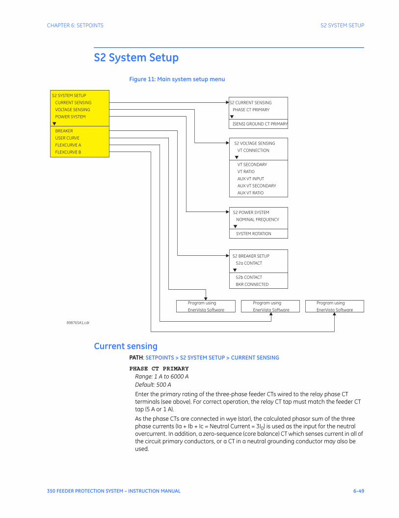
CHAPTER 6: SETPOINTS S2 SYSTEM SETUP
350 FEEDER PROTECTION SYSTEM – INSTRUCTION MANUAL 6–49
S2 System Setup
Figure 11: Main system setup menu
Current sensingPATH: SETPOINTS > S2 SYSTEM SETUP > CURRENT SENSING
PHASE CT PRIMARY
Range: 1 A to 6000 ADefault: 500 A
Enter the primary rating of the three-phase feeder CTs wired to the relay phase CT terminals (see above). For correct operation, the relay CT tap must match the feeder CT tap (5 A or 1 A).As the phase CTs are connected in wye (star), the calculated phasor sum of the three phase currents (Ia + Ib + Ic = Neutral Current = 3I0) is used as the input for the neutral overcurrent. In addition, a zero-sequence (core balance) CT which senses current in all of the circuit primary conductors, or a CT in a neutral grounding conductor may also be used.
Program using
EnerVista Software
S2 CURRENT SENSING
PHASE CT PRIMARY
[SENS] GROUND CT PRIMARY
▼
S2 SYSTEM SETUP
CURRENT SENSING
VOLTAGE SENSING
POWER SYSTEM
BREAKER
USER CURVE
FLEXCURVE A
FLEXCURVE B
▼
898765A1.cdr
S2 VOLTAGE SENSING
VT CONNECTION
VT RATIO
VT SECONDARY
AUX VT INPUT
AUX VT SECONDARY
AUX VT RATIO
▼
S2 BREAKER SETUP
52b CONTACT
52a CONTACT
BKR CONNECTED
▼
S2 POWER SYSTEM
SYSTEM ROTATION
NOMINAL FREQUENCY
▼
Program using
EnerVista Software
Program using
EnerVista Software

6–50 350 FEEDER PROTECTION SYSTEM – INSTRUCTION MANUAL
S2 SYSTEM SETUP CHAPTER 6: SETPOINTS
GROUND [SENS GND] CT PRIMARY
Range: [1 A to 600 A] 1 A to 6000 ADefault: 50 A
For the above configuration, the ground CT primary rating must be entered. To detect low level ground fault currents, the sensitive ground input may be used. In this case, the sensitive ground CT primary rating must be entered. The Sens GND CT primary range is 1 A to 600 AThe relay phase and ground CT types (5 A, 1 A) must match the feeder phase and ground CT taps.
Voltage sensingPATH: SETPOINTS > S2 SYSTEM SETUP > VOLTAGE SENSING
VT CONNECTION
Range: Wye, DeltaDefault: Wye
The 350 provides three-phase VT inputs, that can be wired to either bus VTs or feeder VTs. Select “Wye” connection, if phase-neutral voltages are wired to the relay VT terminals. Select “Delta” connection, if phase-phase voltages from either Delta or Open Delta VTs are connected to the three-phase VT terminals. See the VT connections per the Typical Wiring Diagram in Chapter 2.
VT SECONDARY
Range: 50 V to 240 VDefault: 120 V
This setting defines the voltage across the VT secondary winding when nominal voltage is applied to the primary. On a source of 13.8kV line-line voltage, with a VT ratio of 14400:120 V delta connection, the voltage to be entered is “115 V”. For a Wye connection, the voltage to be entered is 115/ √3 = 66 V.
VT RATIO
Range: 1:1 to 5000:1Default: 1:1
This setting defines the VT primary to secondary turns ratio. For a 14400: 120 VT, the entry would be “120:1” (14400/120 = 120).
AUX VT INPUT
Range: Vab VT, Vbc VT, Vca VT, Van VT, Vbn VT, Vcn VTDefault: Vab VT
The 350 relay provides a voltage input (AUX VT INPUT), where a single feeder/line VT can be connected. The aux. VT voltage can be used for setting up auxiliary under- and over-voltage feeder protection. Select the phase-neutral, or the phase-phase voltage connected to the Aux VT input terminals
AUX VT SECONDARY
Range: 50 V to 240 VDefault: 110 V
This setting defines the voltage across the VT secondary winding when nominal voltage is applied to the primary. On a source of 13.8kV line-line voltage, with a VT ratio of 14400:120 V delta connection, the voltage to be entered is “115 V”. For a Wye connection, the voltage to be entered is 115/√3 = 66 V.
CHAPTER 6: SETPOINTS S2 SYSTEM SETUP
350 FEEDER PROTECTION SYSTEM – INSTRUCTION MANUAL 6–51
AUX VT RATIO
Range: 1:1 to 5000:1Default: 1:1
This setting defines the VT primary to secondary turns ratio. For a 14400: 120 VT, the entry would be “120:1” (14400/120 = 120).
NOTE
NOTE: The 350 relay can be applied to both metering and protection feeders with up to 65 kV phase-to-phase voltage. Please ensure that the selected VT ratio and VT secondary do not result in a primary voltage exceeding 65 kV.
Power systemPATH: SETPOINTS > S2 SYSTEM SETUP > POWER SYSTEM
NOMINAL FREQUENCY
Range: 60 Hz, 50 HzDefault: 60 Hz
Enter the nominal power system frequency. This value is used as a default to set the optimal digital sampling rate.
SYSTEM ROTATION
Range: ABC, ACB, Default: ABC
Enter the phase sequence of the power system.
BreakerThe status of the feeder breaker is monitored by the 350 relay using the status of either one or two contact inputs named 52a (CI#1) and 52b (CI#2) wired to the breaker auxiliary contacts 52a and 52b respectively (see below). The following path is available using the keypad. For instructions on how to use the keypad, please refer to Chapter 3 - Working with the Keypad.PATH: SETPOINTS > S2 SYSTEM SETUP > BREAKER
52a CONTACT
Range: Disabled, 52a (CI#1)Default: Disabled
Select contact input 52a (CI#1) if connected to breaker auxiliary contact 52a.
52b CONTACT
Range: Disabled, 52b (CI#2)Default: Disabled
Select contact input 52b (CI#2) if connected to breaker auxiliary contact 52b.
BKR CONNECTED
Range: Contact Input 3 to 10, DisabledDefault: Disabled
Select a contact input to show whether the breaker is connected (Racked-in, or disconnect switches switched-on), or disconnected (racked-out, or disconnect switches switched-off) to the system.
NOTE
NOTE: It is highly recommended to monitor the status of the feeder breaker using both breaker auxiliary contacts 52a, and 52b, however using only one of them is also acceptable.

6–52 350 FEEDER PROTECTION SYSTEM – INSTRUCTION MANUAL
S2 SYSTEM SETUP CHAPTER 6: SETPOINTS
The breaker status when disconnected from the main power circuit, such by drawout breaker racking mechanism, or isolated by the associated disconnect switches on a fixed circuit breaker, is provided by monitoring the contact input setting for “BKR CONNECTED”.The logic for Breaker Open, and Breaker Close status is shown in the table below:
Table 1: Breaker open / Breaker closed status logic
If the contact input selected under BKR CONNECTED setting is asserted, the breaker is considered connected to the primary system. When the breaker is determined disconnected, the breaker state is shown to be neither open, nor closed.
Table 2: Breaker status with both contacts configured
User curveThere is one user-programmable User Curve available with the 350 system. Refer to the S3 Protection/Current Elements/TOC Curves section for details on how to set the User Curve. Due to the complexity of the configuration, the User Curve is available only through the EnerVista SR3 Setup program.
FlexCurves™There are two user-programmable FlexCurves™ available with the 350 system, labeled A and B. For details on FlexCurves™please refer to S3 Protection/Current Elements/TOC Curves in this manual.
NOTE
NOTE: The User Curve and Flexcurves A and B are available for programming under EnerVista SR3 Setup software.
52a contact configured
52b contact configured
Breaker status
Open Close
Yes Yes 52a contact open52b contact closed
52a contact closed52b contact open
Yes No 52a contact open 52a contact closed
No Yes 52b contact closed 52b contact open
No No Status unknown
52a contact status 52b contact status Breaker status
Off On open
On Off closed
On On BKR status failure
Off Off BKR status failure

CHAPTER 6: SETPOINTS S3 PROTECTION
350 FEEDER PROTECTION SYSTEM – INSTRUCTION MANUAL 6–53
S3 Protection
The 350 protection elements are organized in two identical setpoint groups: Setpoint Group 1 and Setpoint Group 2.Each Setpoint Group has the same protection functions, depending on the relay order code. These protection functions include:• Phase Timed Overcurrent (Phase TOC)• Phase Instantaneous Overcurrent (Phase IOC)• Ground Timed Overcurrent (Ground TOC)• Ground Instantaneous Overcurrent (Ground IOC1, Ground IOC2)• Ground Directional(Ground Dir)• Neutral Timed Overcurrent (Neutral TOC)• Neutral Instantaneous Overcurrent (Neutral IOC1, Neutral IOC2)• Neutral Directional(Neutral Dir)• Negative Sequence Overcurrent (Negative Seq OC)• Phase Undervoltage (Phase UV)• Phase Overvoltage (Phase OV)• Neutral Overvoltage (Neutral OV)• Negative Sequence Overvoltage (Negative Seq OV)• Auxiliary Undervoltage (Auxiliary UV)• Auxiliary Overvoltage (Auxiliary OV)• Underfrequency 1, Underfrequency 2• Overfrequency 1, Overfrequency 2• Thermal Model
6–54 350 FEEDER PROTECTION SYSTEM – INSTRUCTION MANUAL
S3 PROTECTION CHAPTER 6: SETPOINTS
Figure 12: Main protection menu
S3 PROTECTION
SETPOINT GROUP 1
SETPOINT GROUP 2
S5 INPUTS/OUTPUTS
CONTACT INPUTS
OUTPUT RELAYS
VIRTUAL INPUTS
S4 CONTROLS
CHANGE SEPNT GROUP
VIRTUAL INPUTS
LOGIC ELEMENTS
COLD LOAD PICKUP
BREAKER FAIL
AUTORECLOSE
BREAKER CONTROL
▼
S2 SYSTEM SETUP
CURRENT SENSING
VOLTAGE SENSING
POWER SYSTEM
BREAKER
USER CURVE
FLEXCURVE A
FLEXCURVE B
▼
S1 RELAY SETUP
CLOCK
PASSWORD SECURITY
COMMUNICATIONS
EVENT RECORDER
TRANSIENT RECDR
FRONT PANEL
INSTALLATION
▼
SETPOINTS
S1 RELAY SETUP
S2 SYSTEM SETUP
S3 PROTECTION
S4 CONTROLS
S5 INPUTS/OUTPUTS
▼
S3 SETPOINT GROUP 1
PHASE TOC
PHASE IOC1
PHASE IOC2
[SENS] GROUND TOC
[SENS] GROUND IOC1
[SENS]
NEUTRAL TOC
NEUTRAL IOC1
NEUTRAL IOC2
NEG SEQ IOC
PHASE UV
PHASE OV
NEUTRAL OV
NEGATIVE SEQ OV
AUXILIARY UV
AUXILIARY OV
UNDER-FREQUENCY1
UNDER-FREQUENCY2
OVER-FREQUENCY1
OVER-FREQUENCY2
GROUND IOC2
[SENS] GND DIR
NTRL DIR
THERMAL MODEL
▼
S3 SETPOINT GROUP 2
PHASE TOC
PHASE IOC1
PHASE IOC2
[SENS] GROUND TOC
[SENS] GROUND IOC1
[SENS]
NEUTRAL TOC
NEUTRAL IOC1
NEUTRAL IOC2
NEG SEQ IOC
PHASE UV
PHASE OV
NEUTRAL OV
NEGATIVE SEQ OV
AUXILIARY UV
AUXILIARY OV
UNDER-FREQUENCY1
UNDER-FREQUENCY2
OVER-FREQUENCY1
OVER-FREQUENCY2
GROUND IOC2
[SENS] GND DIR
THERMAL MODEL
NTRL DIR
▼
898757A1.cdr
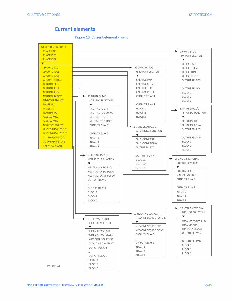
CHAPTER 6: SETPOINTS S3 PROTECTION
350 FEEDER PROTECTION SYSTEM – INSTRUCTION MANUAL 6–55
Current elementsFigure 13: Current elements menu
S3 SETPOINT GROUP 1
PHASE TOC
PHASE IOC1
PHASE IOC2
GROUND TOC
GROUND IOC1
GROUND IOC2
GROUND DIR OC
NEUTRAL TOC
NEUTRAL IOC1
NEUTRAL IOC2
NEUTRAL DIR OC
NEGATIVE SEQ IOC
PHASE UV
PHASE OV
NEUTRAL OV
AUXILIARY UV
AUXILIARY OV
NEGATIVE SEQ OV
UNDER-FREQUENCY1
UNDER-FREQ 2
OVER-FREQ 1
OVER-FREQ 2
UENCY
UENCY
UENCY
THERMAL MODEL
▼
S3 NEUTRAL TOC
NTRL TOC FUNCTION
NEUTRAL TOC PKP
NEUTRAL TOC CURVE
NEUTRAL TOC TDM
NEUTRAL TOC RESET
OUTPUT RELAY 3
...
OUTPUT RELAY 6
BLOCK 1
BLOCK 2
BLOCK 3
▼
S3 NEUTRAL IOC1/2
NTRL IOC1/2 FUNCTION
NEUTRAL IOC1/2 PKP
NEUTRAL IOC1/2 DELAY
NEUTRAL IOC DIRECTION
OUTPUT RELAY 3
...
OUTPUT RELAY 6
BLOCK 1
BLOCK 2
BLOCK 3
▼
S3 GROUND TOC
GND TOC FUNCTION
GND TOC PKP
GND TOC CURVE
GND TOC TDM
GND TOC RESET
OUTPUT RELAY 3
...
OUTPUT RELAY 6
BLOCK 1
BLOCK 2
BLOCK 3
▼
S3 GROUND IOC1/2
GND IOC1/2 FUNCTION
GND IOC1/2 PKP
GND IOC1/2 DELAY
OUTPUT RELAY 3
...
OUTPUT RELAY 6
BLOCK 1
BLOCK 2
BLOCK 3
▼
S3 PHASE TOC
PH TOC FUNCTION
PH TOC PKP
PH TOC CURVE
PH TOC TDM
PH TOC RESET
OUTPUT RELAY 3
...
OUTPUT RELAY 6
BLOCK 1
BLOCK 2
BLOCK 3
▼
S3 PHASE IOC1/2
PH IOC1/2 FUNCTION
PH IOC1/2 PKP
PH IOC1/2 DELAY
OUTPUT RELAY 3
...
OUTPUT RELAY 6
BLOCK 1
BLOCK 2
BLOCK 3
▼
898758A1. cdr
S3 THERMAL MODEL
THERMAL MDL FUNC
THERMAL MDL PKP
THERMAL MDL ALARM
HEAT TIME CONSTANT
COOL TIME CONSTANT
OUTPUT RELAY 3
...
OUTPUT RELAY 6
BLOCK 1
BLOCK 2
BLOCK 3
▼
S3 NEGATIVE SEQ IOC
NEGATIVE SEQ IOC FUNCTN
PKP
DELAY
OUTPUT RELAY 3
...
OUTPUT RELAY 6
BLOCK 1
BLOCK 2
BLOCK 3
NEGATIVE SEQ IOC
NEGATIVE SEQ IOC
▼
S3 NTRL DIRECTIONAL
NTRL DIR FUNCTION
NTRL DIR POLARIZING
NTRL DIR MTA
MIN POL VOLTAGE
OUTPUT RELAY 3
...
OUTPUT RELAY 6
BLOCK 1
BLOCK 2
BLOCK 3
▼
S3 GND DIRECTIONAL
GND DIR FUNCTION
GND DIR MTA
MIN POL VOLTAGE
OUTPUT RELAY 3
...
OUTPUT RELAY 6
BLOCK 1
BLOCK 2
BLOCK 3
▼
6–56 350 FEEDER PROTECTION SYSTEM – INSTRUCTION MANUAL
S3 PROTECTION CHAPTER 6: SETPOINTS
TOC curves DESCRIPTIONThe relay has a total of two phase, two neutral, and two ground/sensitive ground time overcurrent elements. The programming of the time-current characteristics of these elements is identical in all cases and will only be covered in this section. The required curve is established by programming a Pickup Current, Curve Shape, Curve Multiplier, and Reset Time. The Curve Shape can be either a standard shape or a user-defined shape programmed with the FlexCurve™ feature.Accurate coordination may require changing the time overcurrent characteristics of particular elements under different conditions. For picking up a cold load, a different time-current characteristic can be produced by increasing the pickup current value. The following setpoints are used to program the time-current characteristics.• <Element_Name> PICKUP: The pickup current is the threshold current at which the
time overcurrent element starts timing. There is no intentional ‘dead band’ when the current is above the pickup level. However, accuracy is only guaranteed above a 1.5 per unit pickup level. The dropout threshold is 98% of the pickup threshold. Enter the pickup current corresponding to 1 per unit on the time overcurrent curves as a multiple of the source CT. For example, if 100: 5 CTs are used and a pickup of 90 amps is required for the time overcurrent element, enter “0.9 x CT”.
• <Element_Name> CURVE: Select the desired curve shape. If none of the standard curve shapes is appropriate, a custom FlexCurve™ can be created by entering the trip times at 80 different current values; see S2 SYSTEM SETUP > FLEXCURVE A. Curve formulas are given for use with computer based coordination programs. Calculated trip time values are only valid for I / Ipu > 1. Select the appropriate curve shape and multiplier, thus matching the appropriate curve with the protection requirements. The available curves are shown in the table below.
• <Element_Name> MULTIPLIER: A multiplier setpoint allows shifting of the selected base curve in the vertical time direction. Unlike the electromechanical time dial equivalent, trip times are directly proportional to the value of the time multiplier setpoint. For example, all trip times for a multiplier of 10 are 10 times the multiplier 1 or base curve values.When Timed Over-Current is programmed with Definite time, the operating time is obtained after multiplication of the selected Multiplier (TDM) by a 0.1 s base line. For example, selection of TDM = 5 would lead to a 0.5 s operating time.
• <Element_Name> RESET: Time overcurrent tripping time calculations are made with an internal ‘energy capacity’ memory variable. When this variable indicates that the energy capacity has reached 100%, a time overcurrent trip is generated. If less than 100% is accumulated in this variable and the current falls below the dropout threshold of 97 to 99% of the pickup value, the variable must be reduced. Two methods of this resetting operation are available, Instantaneous and Linear. The Instantaneous selection is intended for applications with other relays, such as most static units, which set the energy capacity directly to zero when the current falls below the reset threshold. The Linear selection can be used where the relay must coordinate with electromechanical units. With this setpoint, the energy capacity variable is decremented according to the following equation.
ANSI GE TYPE IAC IEC OTHER
Extremely Inverse Extremely Inverse Curve A (BS142) Definite Time
Very Inverse Very Inverse Curve B (BS142) Flexcurve ATM
Normally Inverse Inverse Curve C (BS142) Flexcurve BTM
Moderately Inverse Short Inverse IEC Short Inverse User Curve
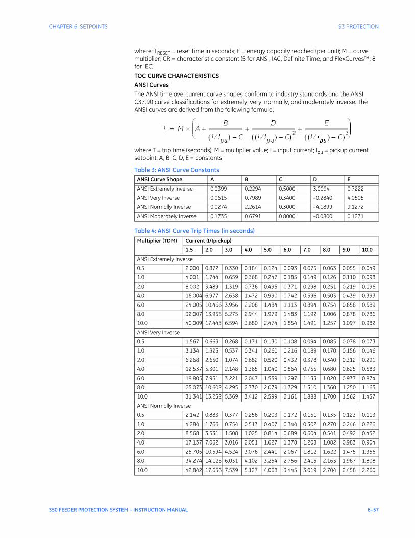
CHAPTER 6: SETPOINTS S3 PROTECTION
350 FEEDER PROTECTION SYSTEM – INSTRUCTION MANUAL 6–57
where: TRESET = reset time in seconds; E = energy capacity reached (per unit); M = curve multiplier; CR = characteristic constant (5 for ANSI, IAC, Definite Time, and FlexCurves™; 8 for IEC)TOC CURVE CHARACTERISTICSANSI CurvesThe ANSI time overcurrent curve shapes conform to industry standards and the ANSI C37.90 curve classifications for extremely, very, normally, and moderately inverse. The ANSI curves are derived from the following formula:
where:T = trip time (seconds); M = multiplier value; I = input current; Ipu = pickup current setpoint; A, B, C, D, E = constants
Table 3: ANSI Curve Constants
Table 4: ANSI Curve Trip Times (in seconds)
ANSI Curve Shape A B C D E
ANSI Extremely Inverse 0.0399 0.2294 0.5000 3.0094 0.7222
ANSI Very Inverse 0.0615 0.7989 0.3400 –0.2840 4.0505
ANSI Normally Inverse 0.0274 2.2614 0.3000 –4.1899 9.1272
ANSI Moderately Inverse 0.1735 0.6791 0.8000 –0.0800 0.1271
Multiplier (TDM) Current (I/Ipickup)
1.5 2.0 3.0 4.0 5.0 6.0 7.0 8.0 9.0 10.0
ANSI Extremely Inverse
0.5 2.000 0.872 0.330 0.184 0.124 0.093 0.075 0.063 0.055 0.049
1.0 4.001 1.744 0.659 0.368 0.247 0.185 0.149 0.126 0.110 0.098
2.0 8.002 3.489 1.319 0.736 0.495 0.371 0.298 0.251 0.219 0.196
4.0 16.004 6.977 2.638 1.472 0.990 0.742 0.596 0.503 0.439 0.393
6.0 24.005 10.466 3.956 2.208 1.484 1.113 0.894 0.754 0.658 0.589
8.0 32.007 13.955 5.275 2.944 1.979 1.483 1.192 1.006 0.878 0.786
10.0 40.009 17.443 6.594 3.680 2.474 1.854 1.491 1.257 1.097 0.982
ANSI Very Inverse
0.5 1.567 0.663 0.268 0.171 0.130 0.108 0.094 0.085 0.078 0.073
1.0 3.134 1.325 0.537 0.341 0.260 0.216 0.189 0.170 0.156 0.146
2.0 6.268 2.650 1.074 0.682 0.520 0.432 0.378 0.340 0.312 0.291
4.0 12.537 5.301 2.148 1.365 1.040 0.864 0.755 0.680 0.625 0.583
6.0 18.805 7.951 3.221 2.047 1.559 1.297 1.133 1.020 0.937 0.874
8.0 25.073 10.602 4.295 2.730 2.079 1.729 1.510 1.360 1.250 1.165
10.0 31.341 13.252 5.369 3.412 2.599 2.161 1.888 1.700 1.562 1.457
ANSI Normally Inverse
0.5 2.142 0.883 0.377 0.256 0.203 0.172 0.151 0.135 0.123 0.113
1.0 4.284 1.766 0.754 0.513 0.407 0.344 0.302 0.270 0.246 0.226
2.0 8.568 3.531 1.508 1.025 0.814 0.689 0.604 0.541 0.492 0.452
4.0 17.137 7.062 3.016 2.051 1.627 1.378 1.208 1.082 0.983 0.904
6.0 25.705 10.594 4.524 3.076 2.441 2.067 1.812 1.622 1.475 1.356
8.0 34.274 14.125 6.031 4.102 3.254 2.756 2.415 2.163 1.967 1.808
10.0 42.842 17.656 7.539 5.127 4.068 3.445 3.019 2.704 2.458 2.260
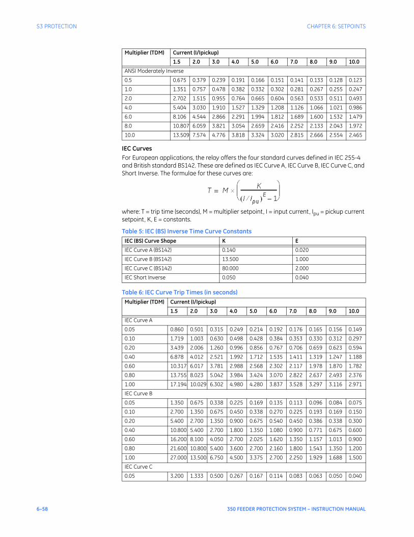
6–58 350 FEEDER PROTECTION SYSTEM – INSTRUCTION MANUAL
S3 PROTECTION CHAPTER 6: SETPOINTS
IEC CurvesFor European applications, the relay offers the four standard curves defined in IEC 255-4 and British standard BS142. These are defined as IEC Curve A, IEC Curve B, IEC Curve C, and Short Inverse. The formulae for these curves are:
where: T = trip time (seconds), M = multiplier setpoint, I = input current, Ipu = pickup current setpoint, K, E = constants.
Table 5: IEC (BS) Inverse Time Curve Constants
Table 6: IEC Curve Trip Times (in seconds)
ANSI Moderately Inverse
0.5 0.675 0.379 0.239 0.191 0.166 0.151 0.141 0.133 0.128 0.123
1.0 1.351 0.757 0.478 0.382 0.332 0.302 0.281 0.267 0.255 0.247
2.0 2.702 1.515 0.955 0.764 0.665 0.604 0.563 0.533 0.511 0.493
4.0 5.404 3.030 1.910 1.527 1.329 1.208 1.126 1.066 1.021 0.986
6.0 8.106 4.544 2.866 2.291 1.994 1.812 1.689 1.600 1.532 1.479
8.0 10.807 6.059 3.821 3.054 2.659 2.416 2.252 2.133 2.043 1.972
10.0 13.509 7.574 4.776 3.818 3.324 3.020 2.815 2.666 2.554 2.465
IEC (BS) Curve Shape K E
IEC Curve A (BS142) 0.140 0.020
IEC Curve B (BS142) 13.500 1.000
IEC Curve C (BS142) 80.000 2.000
IEC Short Inverse 0.050 0.040
Multiplier (TDM) Current (I/Ipickup)
1.5 2.0 3.0 4.0 5.0 6.0 7.0 8.0 9.0 10.0
IEC Curve A
0.05 0.860 0.501 0.315 0.249 0.214 0.192 0.176 0.165 0.156 0.149
0.10 1.719 1.003 0.630 0.498 0.428 0.384 0.353 0.330 0.312 0.297
0.20 3.439 2.006 1.260 0.996 0.856 0.767 0.706 0.659 0.623 0.594
0.40 6.878 4.012 2.521 1.992 1.712 1.535 1.411 1.319 1.247 1.188
0.60 10.317 6.017 3.781 2.988 2.568 2.302 2.117 1.978 1.870 1.782
0.80 13.755 8.023 5.042 3.984 3.424 3.070 2.822 2.637 2.493 2.376
1.00 17.194 10.029 6.302 4.980 4.280 3.837 3.528 3.297 3.116 2.971
IEC Curve B
0.05 1.350 0.675 0.338 0.225 0.169 0.135 0.113 0.096 0.084 0.075
0.10 2.700 1.350 0.675 0.450 0.338 0.270 0.225 0.193 0.169 0.150
0.20 5.400 2.700 1.350 0.900 0.675 0.540 0.450 0.386 0.338 0.300
0.40 10.800 5.400 2.700 1.800 1.350 1.080 0.900 0.771 0.675 0.600
0.60 16.200 8.100 4.050 2.700 2.025 1.620 1.350 1.157 1.013 0.900
0.80 21.600 10.800 5.400 3.600 2.700 2.160 1.800 1.543 1.350 1.200
1.00 27.000 13.500 6.750 4.500 3.375 2.700 2.250 1.929 1.688 1.500
IEC Curve C
0.05 3.200 1.333 0.500 0.267 0.167 0.114 0.083 0.063 0.050 0.040
Multiplier (TDM) Current (I/Ipickup)
1.5 2.0 3.0 4.0 5.0 6.0 7.0 8.0 9.0 10.0
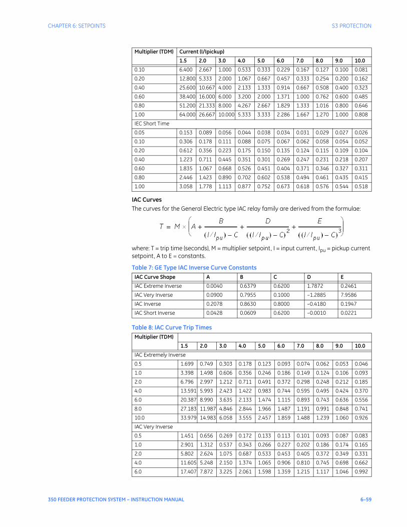
CHAPTER 6: SETPOINTS S3 PROTECTION
350 FEEDER PROTECTION SYSTEM – INSTRUCTION MANUAL 6–59
IAC CurvesThe curves for the General Electric type IAC relay family are derived from the formulae:
where: T = trip time (seconds), M = multiplier setpoint, I = input current, Ipu = pickup current setpoint, A to E = constants.
Table 7: GE Type IAC Inverse Curve Constants
Table 8: IAC Curve Trip Times
0.10 6.400 2.667 1.000 0.533 0.333 0.229 0.167 0.127 0.100 0.081
0.20 12.800 5.333 2.000 1.067 0.667 0.457 0.333 0.254 0.200 0.162
0.40 25.600 10.667 4.000 2.133 1.333 0.914 0.667 0.508 0.400 0.323
0.60 38.400 16.000 6.000 3.200 2.000 1.371 1.000 0.762 0.600 0.485
0.80 51.200 21.333 8.000 4.267 2.667 1.829 1.333 1.016 0.800 0.646
1.00 64.000 26.667 10.000 5.333 3.333 2.286 1.667 1.270 1.000 0.808
IEC Short Time
0.05 0.153 0.089 0.056 0.044 0.038 0.034 0.031 0.029 0.027 0.026
0.10 0.306 0.178 0.111 0.088 0.075 0.067 0.062 0.058 0.054 0.052
0.20 0.612 0.356 0.223 0.175 0.150 0.135 0.124 0.115 0.109 0.104
0.40 1.223 0.711 0.445 0.351 0.301 0.269 0.247 0.231 0.218 0.207
0.60 1.835 1.067 0.668 0.526 0.451 0.404 0.371 0.346 0.327 0.311
0.80 2.446 1.423 0.890 0.702 0.602 0.538 0.494 0.461 0.435 0.415
1.00 3.058 1.778 1.113 0.877 0.752 0.673 0.618 0.576 0.544 0.518
IAC Curve Shape A B C D E
IAC Extreme Inverse 0.0040 0.6379 0.6200 1.7872 0.2461
IAC Very Inverse 0.0900 0.7955 0.1000 –1.2885 7.9586
IAC Inverse 0.2078 0.8630 0.8000 –0.4180 0.1947
IAC Short Inverse 0.0428 0.0609 0.6200 –0.0010 0.0221
Multiplier (TDM)
1.5 2.0 3.0 4.0 5.0 6.0 7.0 8.0 9.0 10.0
IAC Extremely Inverse
0.5 1.699 0.749 0.303 0.178 0.123 0.093 0.074 0.062 0.053 0.046
1.0 3.398 1.498 0.606 0.356 0.246 0.186 0.149 0.124 0.106 0.093
2.0 6.796 2.997 1.212 0.711 0.491 0.372 0.298 0.248 0.212 0.185
4.0 13.591 5.993 2.423 1.422 0.983 0.744 0.595 0.495 0.424 0.370
6.0 20.387 8.990 3.635 2.133 1.474 1.115 0.893 0.743 0.636 0.556
8.0 27.183 11.987 4.846 2.844 1.966 1.487 1.191 0.991 0.848 0.741
10.0 33.979 14.983 6.058 3.555 2.457 1.859 1.488 1.239 1.060 0.926
IAC Very Inverse
0.5 1.451 0.656 0.269 0.172 0.133 0.113 0.101 0.093 0.087 0.083
1.0 2.901 1.312 0.537 0.343 0.266 0.227 0.202 0.186 0.174 0.165
2.0 5.802 2.624 1.075 0.687 0.533 0.453 0.405 0.372 0.349 0.331
4.0 11.605 5.248 2.150 1.374 1.065 0.906 0.810 0.745 0.698 0.662
6.0 17.407 7.872 3.225 2.061 1.598 1.359 1.215 1.117 1.046 0.992
Multiplier (TDM) Current (I/Ipickup)
1.5 2.0 3.0 4.0 5.0 6.0 7.0 8.0 9.0 10.0
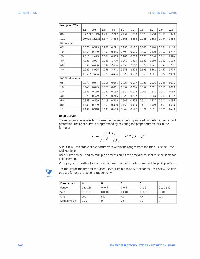
6–60 350 FEEDER PROTECTION SYSTEM – INSTRUCTION MANUAL
S3 PROTECTION CHAPTER 6: SETPOINTS
USER CurvesThe relay provides a selection of user definable curve shapes used by the time overcurrent protection. The User curve is programmed by selecting the proper parameters in the formula:
A, P, Q, B, K - selectable curve parameters within the ranges from the table: D is the Time Dial Multiplier.User Curve can be used on multiple elements only if the time dial multiplier is the same for each element.V = I/IPICKUP (TOC setting) is the ratio between the measured current and the pickup setting.
NOTE
NOTE: The maximum trip time for the User Curve is limited to 65.535 seconds. The User Curve can be used for one protection situation only.
8.0 23.209 10.497 4.299 2.747 2.131 1.813 1.620 1.490 1.395 1.323
10.0 29.012 13.121 5.374 3.434 2.663 2.266 2.025 1.862 1.744 1.654
IAC Inverse
0.5 0.578 0.375 0.266 0.221 0.196 0.180 0.168 0.160 0.154 0.148
1.0 1.155 0.749 0.532 0.443 0.392 0.360 0.337 0.320 0.307 0.297
2.0 2.310 1.499 1.064 0.885 0.784 0.719 0.674 0.640 0.614 0.594
4.0 4.621 2.997 2.128 1.770 1.569 1.439 1.348 1.280 1.229 1.188
6.0 6.931 4.496 3.192 2.656 2.353 2.158 2.022 1.921 1.843 1.781
8.0 9.242 5.995 4.256 3.541 3.138 2.878 2.695 2.561 2.457 2.375
10.0 11.552 7.494 5.320 4.426 3.922 3.597 3.369 3.201 3.072 2.969
IAC Short Inverse
0.5 0.072 0.047 0.035 0.031 0.028 0.027 0.026 0.026 0.025 0.025
1.0 0.143 0.095 0.070 0.061 0.057 0.054 0.052 0.051 0.050 0.049
2.0 0.286 0.190 0.140 0.123 0.114 0.108 0.105 0.102 0.100 0.099
4.0 0.573 0.379 0.279 0.245 0.228 0.217 0.210 0.204 0.200 0.197
6.0 0.859 0.569 0.419 0.368 0.341 0.325 0.314 0.307 0.301 0.296
8.0 1.145 0.759 0.559 0.490 0.455 0.434 0.419 0.409 0.401 0.394
10.0 1.431 0.948 0.699 0.613 0.569 0.542 0.524 0.511 0.501 0.493
Multiplier (TDM)
1.5 2.0 3.0 4.0 5.0 6.0 7.0 8.0 9.0 10.0
Parameters A B P Q K
Range 0 to 125 0 to 3 0 to 3 0 to 2 0 to 1.999
Step 0.0001 0.0001 0.0001 0.0001 0.001
Unit sec sec NA NA sec
Default Value 0.05 0 0.04 1.0 0
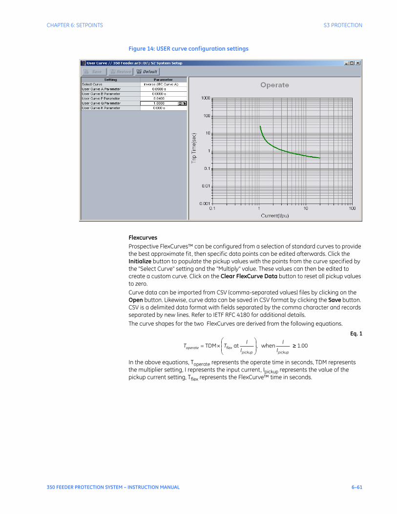
CHAPTER 6: SETPOINTS S3 PROTECTION
350 FEEDER PROTECTION SYSTEM – INSTRUCTION MANUAL 6–61
Figure 14: USER curve configuration settings
FlexcurvesProspective FlexCurves™ can be configured from a selection of standard curves to provide the best approximate fit , then specific data points can be edited afterwards. Click the Initialize button to populate the pickup values with the points from the curve specified by the "Select Curve" setting and the "Multiply" value. These values can then be edited to create a custom curve. Click on the Clear FlexCurve Data button to reset all pickup values to zero.Curve data can be imported from CSV (comma-separated values) files by clicking on the Open button. Likewise, curve data can be saved in CSV format by clicking the Save button. CSV is a delimited data format with fields separated by the comma character and records separated by new lines. Refer to IETF RFC 4180 for additional details.The curve shapes for the two FlexCurves are derived from the following equations.
Eq. 1
In the above equations, Toperate represents the operate time in seconds, TDM represents the multiplier setting, I represents the input current, Ipickup represents the value of the pickup current setting, Tflex represents the FlexCurve™ time in seconds.
when , at TDM×=pickuppickup
flexoperate II
II
TT 1.00
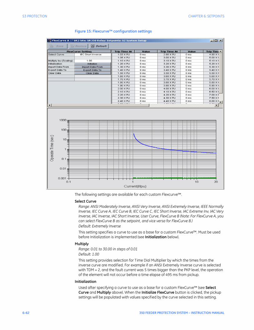
6–62 350 FEEDER PROTECTION SYSTEM – INSTRUCTION MANUAL
S3 PROTECTION CHAPTER 6: SETPOINTS
Figure 15: Flexcurve™ configuration settings
The following settings are available for each custom Flexcurve™.
Select CurveRange: ANSI Moderately Inverse, ANSI Very Inverse, ANSI Extremely Inverse, IEEE Normally Inverse, IEC Curve A, IEC Curve B, IEC Curve C, IEC Short Inverse, IAC Extreme Inv, IAC Very Inverse, IAC Inverse, IAC Short Inverse, User Curve, FlexCurve B (Note: For FlexCurve A, you can select FlexCurve B as the setpoint, and vice versa for FlexCurve B.)Default: Extremely Inverse
This setting specifies a curve to use as a base for a custom FlexCurve™. Must be used before Initialization is implemented (see Initialization below).
MultiplyRange: 0.01 to 30.00 in steps of 0.01Default: 1.00
This setting provides selection for Time Dial Multiplier by which the times from the inverse curve are modified. For example if an ANSI Extremely Inverse curve is selected with TDM = 2, and the fault current was 5 times bigger than the PKP level, the operation of the element will not occur before a time elapse of 495 ms from pickup.
InitializationUsed after specifying a curve to use as a base for a custom FlexCurve™ (see Select Curve and Multiply above). When the Initialize FlexCurve button is clicked, the pickup settings will be populated with values specified by the curve selected in this setting.

CHAPTER 6: SETPOINTS S3 PROTECTION
350 FEEDER PROTECTION SYSTEM – INSTRUCTION MANUAL 6–63
1.03 × Pickup, ..., 20.00 × PickupRange: 0 to 65535 ms in steps of 1Default: 0 ms
These settings specify the time to operate at the following pickup levels 1.03 to 20.00. This data is converted into a continuous curve by linear interpolation between data points. To enter a custom FlexCurve™, enter the operate time for each selected pickup point.
NOTE
NOTE: Each FlexCurve can be configured to provide inverse time characteristic to more than one Time Overcurrent Element. However, for computation of the curve operating times, one must take into account the setting of the Time Delay Multiplier from the FlexCurve menu, and the Time Delay Multiplier setting from TOC menu. The true TDM applied to the TOC element when FlexCurve is selected is the result from the multiplication of both TDM settings. For example, for FlexCurve Multiplier = 5, and Phase TOC Multiplier = 2, the total Time Dial Multiplier will be equal to 10. To avoid confusion, it is suggested to keep the multiplier from the TOC menu equal to 1, and change only the multiplier from the selected FlexCurve. This way, one can see from the FlexCurve setup, the curve operating times as related to the multiples of pickup.
Phase timedovercurrent
protection
The relay has one Phase Time Overcurrent protection element per protection group. The settings of this function are applied to each of the three phases to produce trip or pickup per phase. The TOC pickup flag is asserted, when the current on any phase is above the PKP value. The TOC trip flag is asserted if the element stays picked up for the time defined by the selected inverse curve and the magnitude of the current. The element drops from pickup without operation, if the measured current drops below 97-98% of the pickup value, before the time for operation is reached. The selection of Definite Time as a base time delay of 0.1 s, multiplied by the selected TD multiplier. For example the operating time for TOC set to Definite Time and a TDM set to 5 will result in 5*0.1 = 0.5 s.The following path is available using the keypad. For instructions on how to use the keypad, please refer to Chapter 3 - Working with the Keypad.PATH: SETPOINTS > S3 PROTECTION > SETPOINT GROUP 1(2) > PHASE TOC
PH TOC FUNCTION
Range: Disabled, Latched Alarm, Alarm, TripDefault: Disabled
The selection of the Latched Alarm, Alarm, or Trip setting enables the Phase TOC function. The output relay #1 “Trip” will operate when the Trip setting is selected, and the Phase TOC operates. The “ALARM” LED will not turn on if the TOC operates when set to function Trip. The “ALARM” LED will flash upon phase TOC operation, with the TOC function selected as Alarm, and will self-reset, when the operation clears. If Latched Alarm is selected as a TOC function, the “ALARM” LED will flash during TOC operation, and will stay “ON” after the operation clears until the reset command is initiated. The output relay #1 “Trip” will not operate if the Latched Alarm or Alarm setting is selected.
PH TOC PKP
Range: 0.04 to 20.00 x CT in steps of 0.01 x CTDefault: 1.00 x CT
This setting sets the time overcurrent pickup level. For example, a PKP setting of 0.9 x CT with 300:5 CT translates into 270A primary current.

6–64 350 FEEDER PROTECTION SYSTEM – INSTRUCTION MANUAL
S3 PROTECTION CHAPTER 6: SETPOINTS
PH TOC CURVE
Range: ANSI Extremely/Very/Moderately/Normally Inverse, Definite Time, IEC Curve A/B/C and Short Inverse, IAC Extremely/Very/Inverse/Short, User Curve, FlexCurve A, FlexCurve BDefault: Extremely Inverse
This setting sets the shape of the selected TOC inverse curve. If none of the standard curve shapes is appropriate, a custom User curve, or FlexCurve can be created. Refer to the User curve and the FlexCurve setup for more detail on their configurations and usage.
PH TOC TDM
Range: 0.50 to 20.00 in steps of 0.01Default: 1.00
This setting provides selection for Time Dial Multiplier by which the times from the inverse curve are modified. For example if an ANSI Extremely Inverse curve is selected with TDM = 2, and the fault current was 5 times bigger than the PKP level, the operation of the element will not occur before an elapsed time from pickup, of 495 ms.
PH TOC RESET
Range: Instantaneous, LinearDefault: Instantaneous
The “Instantaneous” reset method is intended for applications with other relays, such as most static relays, which set the energy capacity directly to zero when the current falls below the reset threshold. The “Timed” reset method can be used where the relay must coordinate with electromechanical relays.
OUTPUT RELAY 3 to 6
Range: Do not operate, OperateDefault: Do not operate
Any or all of the output relays 3 to 6 can be selected to operate, upon Phase TOC operation. The selection of relay outputs operation is available no matter whether Latched Alarm, Alarm, or Trip function is selected.
BLOCK 1/2/3
Range: Off, Contact Input 1 to 10[8], Virtual Input 1 to 32, Remote Input 1 to 32, Logic Elements 1 to 16Default: Off
Three blocking inputs are provided in the Phase TOC menu. When any of the selected blocking inputs - Contact input, Virtual Input, Remote Input, or Logic Element - turns on, the phase TOC function will be blocked.
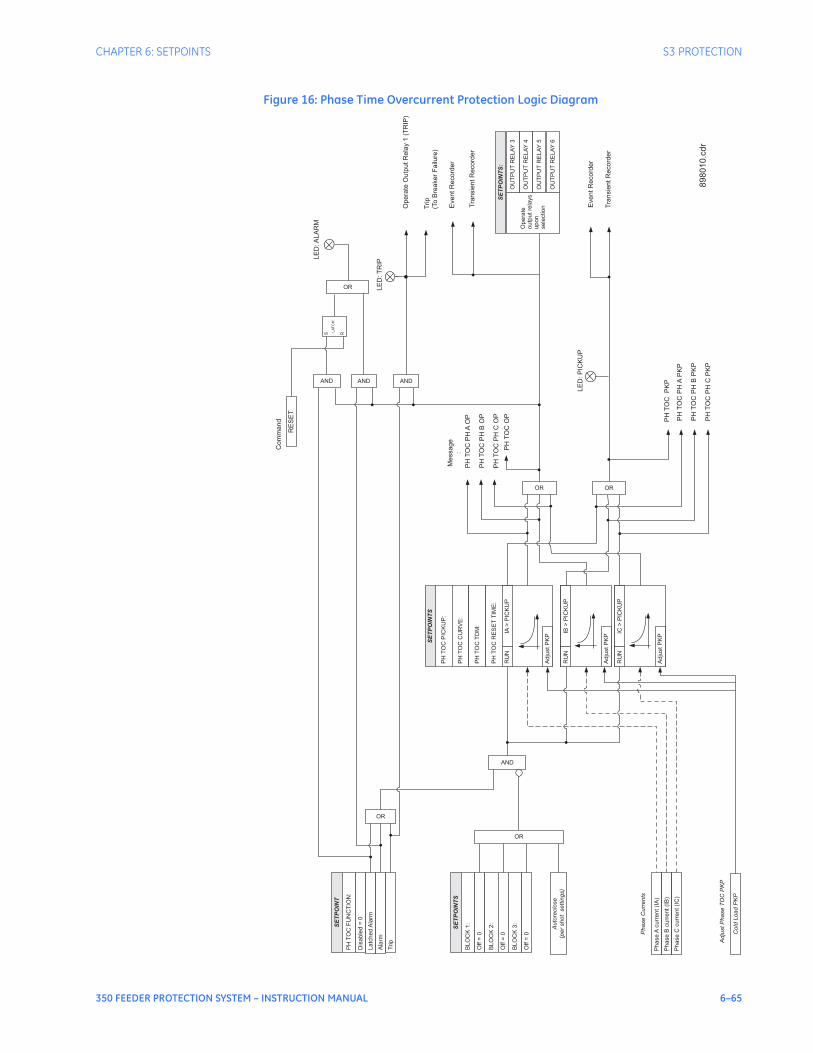
CHAPTER 6: SETPOINTS S3 PROTECTION
350 FEEDER PROTECTION SYSTEM – INSTRUCTION MANUAL 6–65
Figure 16: Phase Time Overcurrent Protection Logic Diagram
SE
TP
OIN
TS
Ph
ase
Acu
rre
nt
(IA
)
SE
TP
OIN
T
PH
TO
CF
UN
CT
ION
:
Dis
ab
led
=0
La
tch
ed
Ala
rm
PH
TO
CP
ICK
UP
:
PH
TO
CC
UR
VE
:
PH
TO
CT
DM
:
AND
Ph
ase
Bcu
rre
nt
(IB
)
Ph
ase
Ccu
rre
nt
(IC
)
OR
Opera
teO
utp
utR
ela
y1
(TR
IP)
EventR
ecord
er
Tra
nsie
ntR
ecord
er
LE
D:P
ICK
UP
LE
D:T
RIP
OR
EventR
ecord
er
Tra
nsie
ntR
ecord
er
Ala
rm
OR
OR
Co
ldL
oa
dP
KP
Ph
ase
Cu
rre
nts
Ad
just
Ph
ase
TO
CP
KP
AND
SE
TP
OIN
TS
:
Op
era
te
ou
tpu
tre
lays
up
on
se
lectio
n
OU
TP
UT
RE
LA
Y4
OU
TP
UT
RE
LA
Y5
OU
TP
UT
RE
LA
Y6
OU
TP
UT
RE
LA
Y3
Trip
AND
Trip
(To
Bre
aker
Failure
)
PH
TO
CP
HA
OP
PH
TO
CP
HB
OP
PH
TO
CP
HC
OP
Message
:
PH
TO
CO
P
PH
TO
CP
HA
PK
P
PH
TO
CP
HB
PK
P
PH
TO
CP
HC
PK
P
PH
TO
CP
KP
PH
TO
CR
ES
ET
TIM
E:
RU
NIA
>P
ICK
UP
RU
NIB
>P
ICK
UP
RU
NIC
>P
ICK
UP
Ad
just
PK
P
Ad
just
PK
P
Ad
just
PK
P
SE
TP
OIN
TS
BL
OC
K1
:
Off
=0
BL
OC
K2
:
Off
=0
BL
OC
K3
:
Off
=0
OR
Au
tore
clo
se
(pe
rsh
ot
se
ttin
gs)
LE
D:A
LA
RM
RE
SE
T
Com
mand
AND
S R
LA
TC
H
89
80
10
.cd
r
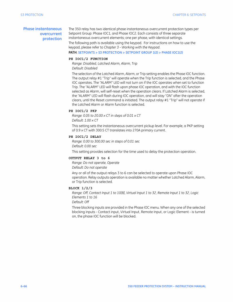
6–66 350 FEEDER PROTECTION SYSTEM – INSTRUCTION MANUAL
S3 PROTECTION CHAPTER 6: SETPOINTS
Phase instantaneousovercurrent
protection
The 350 relay has two identical phase instantaneous overcurrent protection types per Setpoint Group: Phase IOC1, and Phase IOC2. Each consists of three separate instantaneous overcurrent elements; one per phase, with identical settings.The following path is available using the keypad. For instructions on how to use the keypad, please refer to Chapter 3 - Working with the Keypad.PATH: SETPOINTS > S3 PROTECTION > SETPOINT GROUP 1(2) > PHASE IOC1(2)
PH IOC1/2 FUNCTION
Range: Disabled, Latched Alarm, Alarm, TripDefault: Disabled
The selection of the Latched Alarm, Alarm, or Trip setting enables the Phase IOC function. The output relay #1 “Trip” will operate when the Trip function is selected, and the Phase IOC operates. The “ALARM” LED will not turn on if the IOC operates when set to function Trip. The “ALARM” LED will flash upon phase IOC operation, and with the IOC function selected as Alarm, will self-reset when the operation clears. If Latched Alarm is selected, the “ALARM” LED will flash during IOC operation, and will stay “ON” after the operation clears, until the Reset command is initiated. The output relay #1 “Trip” will not operate if the Latched Alarm or Alarm function is selected.
PH IOC1/2 PKP
Range: 0.05 to 20.00 x CT in steps of 0.01 x CTDefault: 1.00 x CT
This setting sets the instantaneous overcurrent pickup level. For example, a PKP setting of 0.9 x CT with 300:5 CT translates into 270A primary current.
PH IOC1/2 DELAY
Range: 0.00 to 300.00 sec in steps of 0.01 secDefault: 0.00 sec
This setting provides selection for the time used to delay the protection operation.
OUTPUT RELAY 3 to 6
Range: Do not operate, OperateDefault: Do not operate
Any or all of the output relays 3 to 6 can be selected to operate upon Phase IOC operation. Relay outputs operation is available no matter whether Latched Alarm, Alarm, or Trip function is selected.
BLOCK 1/2/3
Range: Off, Contact Input 1 to 10[8], Virtual Input 1 to 32, Remote Input 1 to 32, Logic Elements 1 to 16Default: Off
Three blocking inputs are provided in the Phase IOC menu. When any one of the selected blocking inputs - Contact input, Virtual Input, Remote Input, or Logic Element - is turned on, the phase IOC function will be blocked.
CHAPTER 6: SETPOINTS S3 PROTECTION
350 FEEDER PROTECTION SYSTEM – INSTRUCTION MANUAL 6–67
Figure 17: Phase instantaneous overcurrent protection logic diagram
SE
TP
OIN
T
Ph
ase
Acu
rre
nt
(IA
)
RU
N
SE
TP
OIN
T
PH
IOC
FU
NC
TIO
N:
Dis
ab
led
=0
La
tch
ed
Ala
rm
PH
IOC
PIC
KU
P:
PH
IOC
PK
PD
EL
AY
:
AND
Ph
ase
Bcu
rre
nt
(IB
)
Ph
ase
Ccu
rre
nt
(IC
)
RU
N
RU
N
Op
era
teO
utp
ut
Re
lay
1(T
RIP
)
Eve
nt
Re
co
rde
r
Tra
nsie
nt
Re
co
rde
r
LE
D:
PIC
KU
P
LE
D:T
RIP
Eve
nt
Re
co
rde
r
Tra
nsie
nt
Re
co
rde
r
Ala
rm
OR
OR
Co
ldL
oa
dP
KP
Au
tore
clo
se
(pe
rsh
ot
se
ttin
gs)
Ph
ase
Cu
rre
nts
Blo
ck
Inp
uts
AND
SE
TP
OIN
T:
Op
era
te
ou
tpu
tre
lays
up
on
se
lectio
n
OU
TP
UT
RE
LA
Y4
OU
TP
UT
RE
LA
Y5
OU
TP
UT
RE
LA
Y6
OU
TP
UT
RE
LA
Y3
Trip
AND
SE
TP
OIN
T
BL
OC
K1
:
Off
=0
BL
OC
K2
:
Off
=0
BL
OC
K3
:
Off
=0
OR
Me
ssa
ge
Ph
ase
IOC
OP
IB>
PIC
KU
P
IA>
PIC
KU
P
IC>
PIC
KU
P
SE
TP
OIN
T
Ph
ase
IOC
AO
P
Ph
ase
IOC
BO
P
Ph
ase
IOC
CO
P
Ph
ase
IOC
AP
KP
Ph
ase
IOC
BP
KP
Ph
ase
IOC
CP
KP
Ph
ase
IOC
PK
P
Me
ssa
ge
t PK
P
0
t PK
P
0
t PK
P
0
OR
OR
Trip
(To
Bre
ake
rF
ailu
re)
LE
D:A
LA
RM
RE
SE
T
Co
mm
an
d
AND
S R
LA
TC
H
89
80
09
.cd
r

6–68 350 FEEDER PROTECTION SYSTEM – INSTRUCTION MANUAL
S3 PROTECTION CHAPTER 6: SETPOINTS
Ground/SensitiveGround timed
overcurrentprotection
The relay has one Ground Time Overcurrent protection per setpoint group. The settings of this function are applied to the ground input current to produce trip or pickup flags. The Ground TOC pickup flag is asserted, when the ground current is above the PKP value. The Ground TOC operate flag is asserted if the element stays picked up for the time defined by the selected inverse curve, and the magnitude of the current. The element drops from pickup without operation if the measured current drops below 97 to 98% of the pickup value, before the time to operate is reached. The selection of Definite Time has a base time delay of 0.1 s, multiplied by the selected TD multiplier. For example the operating time for TOC set to Definite Time and a TDM set to 5 will result in 5*0.1 = 0.5 s. The following path is available using the keypad. For instructions on how to use the keypad, please refer to Chapter 3 - Working with the Keypad.PATH: SETPOINTS > S3 PROTECTION > SETPOINT GROUP 1(2) > GROUND TOC
NOTE
NOTE: The settings from the menu for Sensitive Ground TOC, appears only upon selection of the Sensitive Ground CT when ordering the relay. Otherwise, the relay displays the menu for Ground TOC protection.
GND TOC FUNCTION
Range: Disabled, Trip, Alarm, Latched AlarmDefault: Disabled
The selection of the Latched Alarm, Alarm, or Trip setting enables the Ground/Sensitive Ground TOC function. The output relay #1 “Trip” will operate, if the Ground/Sensitive Ground TOC function is selected as Trip, and the measured ground current satisfies the operating condition set by the settings. The “ALARM” LED will not turn on if the TOC operates when set to the Trip function. The “ALARM” LED will flash upon phase TOC operation, with the TOC function selected as Alarm, and will self-reset, when this operation clears. If Latched Alarm is selected as the TOC function, the “ALARM” LED will flash during TOC operation, and will stay “ON” after the condition clears, until the reset command is initiated. The output relay #1 “Trip” will not operate if the Latched Alarm or Alarm function is selected. Any or all of output relays 3 to 6 can be selected to operate when the Ground TOC function is selected as Latched Alarm, Alarm, or Trip.
GND TOC PKP
Range: 0.04 to 20.00 x CT in steps of 0.01 x CTDefault: 1.00 x CT
SENS.GND TOC PKP
Range: 0.005 to 3.00 x CT in steps of 0.001 x CTDefault: 1.00 x CT
This setting sets the time overcurrent pickup level. For example, a PKP setting of 0.9 x CT with 300:5 CT translates into 270A primary current.
GND TOC CURVE
Range: ANSI Extremely/Very/Moderately/Normally Inverse, Definite Time, IEC Curve A/B/C and Short Inverse, IAC Extremely/Very/Inverse/Short, User Curve, FlexCurve A, FlexCurve BDefault: Extremely Inverse
This setting sets the shape of the selected over-current inverse curve. If none of the standard curve shapes is appropriate, a custom User curve, or FlexCurve can be created. Refer to the User curve and the FlexCurve setup for more detail on their configurations and usage.

CHAPTER 6: SETPOINTS S3 PROTECTION
350 FEEDER PROTECTION SYSTEM – INSTRUCTION MANUAL 6–69
GND TOC TDM
Range: 0.50 to 20.00 in steps of 0.01Default: 1.0
This setting provides selection for Time Dial Multiplier by which the times from the inverse curve are modified. For example if an ANSI Extremely Inverse curve is selected with TDM = 2, and the fault current was 5 times bigger than the PKP level, the operation of the element will not occur before an elapsed time from pickup, of 495 ms.
GND TOC RESET
Range: Instantaneous, LinearDefault: Instantaneous
The “Instantaneous” reset method is intended for applications with other relays, such as most static relays, which set the energy capacity directly to zero when the current falls below the reset threshold. The “Timed” reset method can be used where the relay must coordinate with electromechanical relays.
OUTPUT RELAY 3 to 6
Range: Do not operate, OperateDefault: Do not operate
Any or all of the output relays 3 to 6 can be selected to operate upon Ground TOC operation. The selection of relay outputs operation is available no matter whether Latched Alarm, Alarm, or Trip function is selected.
BLOCK 1/2/3
Range: Off, Contact Input 1 to 10[8], Virtual Input 1 to 32, Remote Input 1 to 32, Logic Elements 1 to 16Default: Off
Three blocking inputs are provided in the Ground TOC menu. When any of the selected blocking inputs - Contact input, Virtual Input, Remote Input, or Logic Element - turn on, the ground TOC function is blocked.
6–70 350 FEEDER PROTECTION SYSTEM – INSTRUCTION MANUAL
S3 PROTECTION CHAPTER 6: SETPOINTS
Figure 18: Ground/Sensitive Ground timed overcurrent protection: Logic Diagram
SE
TP
OIN
TS
RU
N
SE
TP
OIN
T
GN
DT
OC
FU
NC
TIO
N:
Dis
able
d=
0
Ala
rm
GN
DT
OC
PIC
KU
P:
GN
DT
OC
CU
RV
E:
GN
DT
OC
TD
MU
LT
IPLIE
R:
Ig>
PIC
KU
P
AND
Op
era
teO
utp
ut
Re
lay
1(T
RIP
)
Eve
nt
Re
co
rde
r
Tra
nsie
nt
Re
co
rde
r
LE
D:
PIC
KU
PG
ND
TO
CP
KP
LE
D:T
RIP
Eve
nt
Re
co
rde
r
Tra
nsie
nt
Re
co
rde
r
Latc
hed
Ala
rm
OR
OR
Me
ssa
ge
:
GN
DT
OC
OP
Adju
stP
KP
Adju
stG
nd/S
.Gnd
TO
CP
KP
AND
SE
TP
OIN
TS
:
Opera
te
outp
utre
lays
upon
sele
ction
OU
TP
UT
RE
LA
Y4
OU
TP
UT
RE
LA
Y5
OU
TP
UT
RE
LA
Y6
OU
TP
UT
RE
LA
Y3
Trip
AND
Trip
(To
Bre
ake
rF
ailu
re)
GN
DT
OC
RE
SE
T:
Gro
und/S
ens.G
round
curr
ent(I
g)
Fro
mG
round
CT
or,
Fro
mS
ens.G
round
CT
SE
TP
OIN
TS
BLO
CK
1:
Off
=0
BLO
CK
2:
Off
=0
BLO
CK
3:
Off
=0
OR
Auto
reclo
se
(per
shot
settin
gs)
Cold
Load
PK
P
LE
D:A
LA
RM
RE
SE
T
Co
mm
an
d
AND
S R
LA
TC
H
89
80
06
.cd
r

CHAPTER 6: SETPOINTS S3 PROTECTION
350 FEEDER PROTECTION SYSTEM – INSTRUCTION MANUAL 6–71
Ground/SensitiveGround instantaneous
overcurrentprotection
The relay has one Ground/Sensitive Ground Instantaneous Overcurrent protection element per setpoint group. The settings of these functions are applied to the gound/sensitive ground current for pickup and trip flags. The Ground IOC pickup flag is asserted, when the ground current is above the PKP value. The Ground IOC operate flag is asserted if the element stays picked up for the time defined by the Ground IOC PKP Delay setting. If the pickup time delay is set to 0.00 seconds, the pickup and operate flags will be asserted at the same time. The element drops from pickup without operation, if the ground current drops below 97-99% of the pickup value.The following path is available using the keypad. For instructions on how to use the keypad, please refer to Chapter 3 - Working with the Keypad.PATH: SETPOINTS > S3 PROTECTION > SETPOINT GROUP 1(2) > GROUND IOC1(2)
GND IOC FUNCTION
Range: Disabled, Trip, Alarm, Latched AlarmDefault: Disabled
The selection of the Latched Alarm, Alarm, or Trip setting enables the Ground/Sensitive Ground IOC function. The output relay #1 “Trip” will operate, if the Ground/Sensitive Ground IOC function is selected as Trip, and the measured ground current satisfies the operating condition set by the settings. The “ALARM” LED will not turn on if the element operates when set to function Trip. The “ALARM” LED will flash upon IOC operation, with the IOC function selected as Alarm, and will self-reset, when this operation clears. If Latched Alarm is selected as an IOC function, the “ALARM” LED will flash during the IOC operating condition, and will stay “ON” after the condition clears, until a reset command is initiated. The output relay #1 “Trip” will not operate if Latched Alarm or Alarm setting is selected. Any or all of the output relays 3 to 6 can be selected to operate when the Ground/S.Ground IOC function is selected as Latched Alarm, Alarm, or Trip.
GND IOC PKP
Range: Disabled, 0.05 to 20.00 x CT in steps of 0.01 x CTDefault: 1.00 x CT
SENS.GND IOC PKP
Range: 0.005 to 3.00 x CT in steps of 0.001 x CTDefault: 1.00 x CT
This setting sets the ground overcurrent pickup level specified per times CT. For example, a PKP setting of 0.9 x CT with 300:5 CT translates into 270A primary current.
GND IOC DELAY
Range: 0.00 to 300.00 sec in steps of 0.01 secDefault: 0.00 sec
This setting provides selection for pickup time delay used to delay the operation of the protection.
OUTPUT RELAY 3 to 6
Range: Do not operate, OperateDefault: Do not operate
Any or all of the output relays 3 to 6 can be selected to operate upon Ground IOC operation. The selection of relay outputs operation is available no matter whether Latched Alarm, Alarm, or Trip function is selected.
BLOCK 1/2/3
Range: Off, Contact Input 1 to 10[8], Virtual Input 1 to 32, Remote Input 1 to 32, Logic Element 1 to 16Default: Off
Three blocking inputs are provided in the Ground IOC menu. When any of the selected blocking inputs - Contact input, Virtual Input, Remote Input, or Logic Element - turns on, the ground IOC function is blocked.
6–72 350 FEEDER PROTECTION SYSTEM – INSTRUCTION MANUAL
S3 PROTECTION CHAPTER 6: SETPOINTS
Figure 19: Ground/Sensitive Ground instantaneous overcurrent protection logic diagram
SE
TP
OIN
T
Gro
un
d/S
en
s.
Gro
un
dcu
rre
nt
(Ig
)
RU
N
SE
TP
OIN
T
BL
OC
K1
:
Off
=0
GN
DIO
CP
ICK
UP
:
Ig>
PIC
KU
P
BL
OC
K2
:
Off
=0
BL
OC
K3
:
Off
=0
OR
AND
Op
era
teO
utp
ut
Re
lay
1(T
RIP
)
Eve
nt
Re
co
rde
r
Tra
nsie
nt
Re
co
rde
r
LE
D:T
RIP
OR
OR
Co
ldL
oa
dP
KP
Fro
mG
rou
nd
CT
or,
Fro
mS
en
s.
Gro
un
dC
T
Blo
ck
Inp
uts
AND
SE
TP
OIN
T:
Op
era
te
ou
tpu
tre
lays
up
on
se
lectio
n
OU
TP
UT
RE
LA
Y4
OU
TP
UT
RE
LA
Y5
OU
TP
UT
RE
LA
Y6
OU
TP
UT
RE
LA
Y3
AND
Trip
(To
Bre
ake
rF
ailu
re)
SE
TP
OIN
T
GN
DIO
CF
UN
CT
ION
:
Dis
ab
led
=0
La
tch
ed
Ala
rm
Ala
rm
Trip
GN
DIO
CP
KP
DE
LA
Y:
SE
TP
OIN
T
t PK
P
0
Eve
nt
Re
co
rde
r
Tra
nsie
nt
Re
co
rde
r
Au
tore
clo
se
(pe
rsh
ot
se
ttin
gs)
LE
D:A
LA
RM
RE
SE
T
Co
mm
an
d
AND
S R
LA
TC
H
LE
D:
PIC
KU
PG
rou
nd
IOC
PK
P
Me
ssa
ge
:
Gro
un
dIO
CO
P
89
80
05
.cd
r
CHAPTER 6: SETPOINTS S3 PROTECTION
350 FEEDER PROTECTION SYSTEM – INSTRUCTION MANUAL 6–73
Ground directional The Ground Directional element is used to discriminate whether a fault occurs in a forward or in a reverse direction, and it can be used either individually or as a part of the Ground Time, or Instantaneous over-current elements. (See the setup for Ground TOC, and Ground IOC elements.)The operating current for the Ground directional element is the measured current from the ground CT input terminals. Depending on the ground CT connection, the measured current from the CT terminals can be either the current from a zero sequence CT, or the zero sequence current from a residual CT connection (see figure below).
The polarizing signal for the Ground Directional element is based on the zero sequence voltage. Depending on the relay’s order code, the zero sequence voltage used for the polarizing voltage, is either calculated, when three-phase voltages are available, or is measured from the auxiliary voltage input Vx when the three-phase voltages are not available. For those relays with available phase VTs, the polarizing voltage for the Neutral directional element is calculated as follows:
Eq. 2
Please note, that the phase VT inputs must be connected in Wye.For those relays with available Vx auxiliary voltage input only, the polarizing voltage for the Ground directional element is the zero sequence voltage measured at the Vx terminals. The Vx input should be connected to measure 3V0 from an open delta VT configuration as shown on the figure below.
SOURCE
898730.CDR898730.CDR
A
B
C
USED FOR POLARIZINGUSED FOR POLARIZING
GROUND CURRENT INPUTGROUND CURRENT INPUT
SR350
PHASE CURRENTPHASE CURRENT
INPUTS
A B C
GROUND CURRENT INPUTGROUND CURRENT INPUT
WITH ZERO SEQUENCE CTWITH ZERO SEQUENCE CT
GROUND CURRENT INPUTGROUND CURRENT INPUT
WITH RESIDUAL CONNECTIONWITH RESIDUAL CONNECTION
E8 D8
G
GROUND
I N NIG
E5
D5 D6
E6
D7
E7
GIN
GROUND
D8 E8
GROUND
D8E8
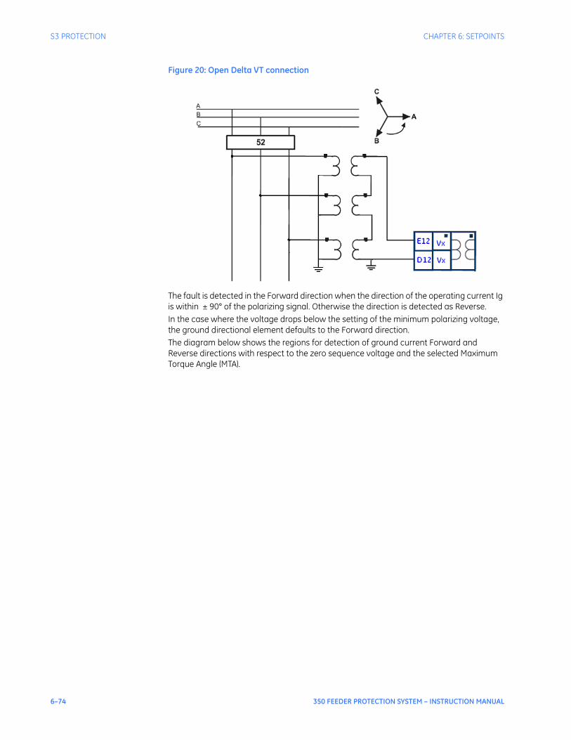
6–74 350 FEEDER PROTECTION SYSTEM – INSTRUCTION MANUAL
S3 PROTECTION CHAPTER 6: SETPOINTS
Figure 20: Open Delta VT connection
The fault is detected in the Forward direction when the direction of the operating current Ig is within ± 90° of the polarizing signal. Otherwise the direction is detected as Reverse.In the case where the voltage drops below the setting of the minimum polarizing voltage, the ground directional element defaults to the Forward direction.The diagram below shows the regions for detection of ground current Forward and Reverse directions with respect to the zero sequence voltage and the selected Maximum Torque Angle (MTA).

CHAPTER 6: SETPOINTS S3 PROTECTION
350 FEEDER PROTECTION SYSTEM – INSTRUCTION MANUAL 6–75
The following path is available using the keypad. For instructions on how to use the keypad, please refer to Chapter 3 - Working with the Keypad.PATH: SETPOINTS > S3 PROTECTION > S3 SETPOINT GROUP 1(2) > NTRL DIR
GND (S.GND) DIR FUNCTION
Range: Disabled, Latched Alarm, Alarm, ControlDefault: Disabled
When the Alarm function is selected, the alarm LED will flash upon detection of Reverse direction, and will drop out when the direction changes to Forward. When Latched Alarm is selected, the alarm LED will flash upon detection of Reverse direction, and will stay lit (latched) after the direction changes to Forward. The alarm LED can be reset by issuing a Reset command. Detection of Reverse direction when the Control function is selected, does not trigger the alarm LED.
GND (S.GND) DIR MTA
Range: 0° to 359° lead in steps of 1°Default: 315°
This setting sets the Maximum Torque Angle (MTA), for the Ground Directional element to define the regions of Forward and Reverse directions. For Voltage polarizing, enter the maximum torque angle by which the operating current leads the polarizing voltage. This is the angle of maximum sensitivity.

6–76 350 FEEDER PROTECTION SYSTEM – INSTRUCTION MANUAL
S3 PROTECTION CHAPTER 6: SETPOINTS
MIN POL VOLTAGE
Range: 0.05 to 1.25 x VT in steps of 0.01Default: 0.05 x VT
The minimum zero sequence voltage level must be selected to prevent operation due to normal system unbalances, or voltage transformer errors. Set the minimum zero sequence voltage level to 2% of VT for well balanced systems, and 1% of VT accuracy. For systems with high resistance grounding or floating neutrals, this setting can be as high as 20%. The default of 5% of VT is appropriate for most solidly grounded systems. The following table shows the operating current, and the polarizing signals used for directional control:
Table 9: Ground Directional characteristics
OUTPUT RELAY 3 to 6
Range: Do not operate, OperateDefault: Do not operate
Any or all of the output relays 3 to 6 can be selected to operate upon Gnd (S. Gnd) Directional operation. The selection of relay outputs operation is available no matter whether Latched Alarm, Alarm, or Trip function is selected.
BLOCK 1/2/3
Range: Off, Contact Input 1 to 10[8], Virtual Input 1 to 32, Remote Input 1 to 32, Logic Element 1 to 16Default: Off
Three blocking inputs are provided in the Ground Directional menu. One blocking input going “high” is enough to block the function. The selection for each block can be Contact input, Virtual Input, Remote Input, or Logic Element.
Quantity Operating Current Polarizing Voltage
Ground Ig -Vo
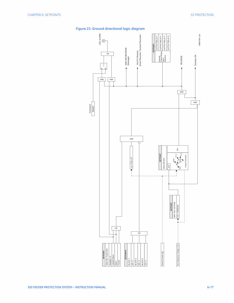
CHAPTER 6: SETPOINTS S3 PROTECTION
350 FEEDER PROTECTION SYSTEM – INSTRUCTION MANUAL 6–77
Figure 21: Ground directional logic diagram
Zero
Sequence
Voltage
(-V
0)
SE
TP
OIN
T
GN
DD
IRF
UN
CT
ION
Dis
able
d=
0
Latc
hed
Ala
rm
SE
TP
OIN
TS
BLO
CK
1
Off
=0
BLO
CK
2
Off
=0
BLO
CK
3
Off
=0
OR
GN
DD
IRR
EV
ER
SE
Ala
rm
OR
OR
RE
VE
RS
E
(Message)
AND
SE
TP
OIN
T:
Opera
te
Outp
utR
ela
ys
Upon
Sele
ction
OU
TP
UT
RE
LA
Y4
OU
TP
UT
RE
LA
Y5
OU
TP
UT
RE
LA
Y6
OU
TP
UT
RE
LA
Y3
Contr
ol
Gro
und
Curr
ent(I
g)
Voltage
Pola
rization
-3V
_0
3I_
0
FW
D
RE
V
RE
V
RU
N
SE
TP
OIN
T
GN
DD
IRM
TA
SE
TP
OIN
T
MIN
PO
LV
OLTA
GE
|V0|>
MIN
IMU
M
Ig>
0.0
5x
CT
AND
AND
AND
Gnd
Dir
Revers
e
(EventR
ecord
er,
Tra
nsie
ntR
ecord
er)
Direction
OK
LE
D:A
LA
RM
RE
SE
T
Com
mand
89
80
18
A1
.cd
r
AND
LA
TC
H
S R

6–78 350 FEEDER PROTECTION SYSTEM – INSTRUCTION MANUAL
S3 PROTECTION CHAPTER 6: SETPOINTS
Neutral timedovercurrent
protection
The relay has one Neutral Time Overcurrent protection element per setpoint group. The settings of this function are applied to the calculated neutral current to produce pickup and trip flags. The Neutral TOC pickup flag is asserted, when the neutral current is above the PKP value. The Neutral TOC operate flag is asserted if the element stays picked up for the time defined by the selected inverse curve and the magnitude of the current. The element drops from pickup without operation, if the neutral current drops below 97-99% of the pickup value, before the time for operation is reached. The selection of Definite Time has a base time delay of 0.1 s, multiplied by the selected TD multiplier. For example the operating time for TOC set to Definite Time and a TDM set to 5 will result in 5*0.1 = 0.5 s. The following path is available using the keypad. For instructions on how to use the keypad, please refer to Chapter 3 - Working with the Keypad.PATH: SETPOINTS > S3 PROTECTION > SETPOINT GROUP 1(2) > NEUTRAL TOC
NTRL TOC FUNCTION
Range: Disabled, Latched Alarm, Alarm, TripDefault: Disabled
The selection of the Latched Alarm, Alarm, or Trip setting enables the Neutral TOC function. The output relay #1 “Trip” will operate if the Neutral TOC function is selected as Trip, and the neutral current calculated by the relay satisfies the operating condition set by the settings. The “ALARM” LED will not turn on if the TOC operates when set to function Trip. The “ALARM” LED will flash upon Neutral TOC operating condition with the TOC function selected as Alarm, and will self-reset when the operating condition clears. If Latched Alarm is selected as a TOC function, the “ALARM” LED will flash during TOC operation, and will stay “ON” after the operation clears, until a reset command is initiated. The output relay #1 “Trip” will not operate if Latched Alarm or Alarm setting is selected. Any or all of the output relays 3 to 6 can be selected to operate when the Neutral TOC function is selected as Latched Alarm, Alarm, or Trip.
NTRL TOC PKP
Range: 0.05 to 20.00 x CT in steps of 0.01 x CTDefault: 1.00 x CT
This setting sets the time overcurrent pickup level. For example, a PKP setting of 0.9 x CT with 300:5 CT translates into 270A neutral current.
NTRL TOC CURVE
Range: ANSI Extremely/Very/Moderately/Normally Inverse, Definite Time, IEC Curve A/B/C and Short Inverse, IAC Extremely/Very/Inverse/Short, User Curve, FlexCurve A, FlexCurve BDefault: Extremely Inverse
This setting sets the shape of the selected over-current inverse curve. If none of the standard curve shapes is appropriate, a custom User curve, or FlexCurve can be created. Refer to the User curve and the FlexCurve setup for more detail on their configurations and usage.
NTRL TOC TDM
Range: 0.50 to 20.00 in steps of 0.01Default: 1.00
This setting provides selection for Time Dial Multiplier by which the times from the selected inverse curve are modified. For example if an ANSI Extremely Inverse curve is selected with TDM = 2, and the fault current was 5 times bigger than the PKP level, operation of the element will not occur before an elapse of 495 ms from pickup.

CHAPTER 6: SETPOINTS S3 PROTECTION
350 FEEDER PROTECTION SYSTEM – INSTRUCTION MANUAL 6–79
NTRL TOC RESET
Range: Instantaneous, LinearDefault: Instantaneous
The “Instantaneous” reset method is intended for applications with other relays, such as most static relays, which set the energy capacity directly to zero when the current falls below the reset threshold. The “Timed” reset method can be used where the relay must coordinate with electromechanical relays.
NTRL TOC DIRECTION
Range: Disabled, Forward, ReverseDefault: Disabled
This setting provides control to the Neutral TOC function in terms of permitting operation under fault conditions in the selected current flow direction, and blocking it when faults occur in the opposite direction.
OUTPUT RELAY 3 to 6
Range: Do not operate, OperateDefault: Do not operate
Any or all of the output relays 3 to 6 can be selected to operate, upon Neutral TOC operation. The selection of relay outputs operation is available no matter whether Latched Alarm, Alarm, or Trip function is selected.
BLOCK 1/2/3
Range: Off, Contact Input 1 to 10[8], Virtual Input 1 to 32, Remote Input 1 to 32, Logic Element 1 to 16Default: Off
There are three blocking inputs provided in the Neutral TOC menu. One blocking input going “high” is enough to block the function. The selection for each block can include Contact input, Virtual Input, Remote Input, or Logic Element.
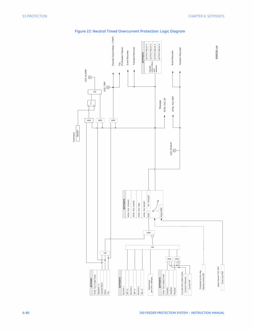
6–80 350 FEEDER PROTECTION SYSTEM – INSTRUCTION MANUAL
S3 PROTECTION CHAPTER 6: SETPOINTS
Figure 22: Neutral Timed Overcurrent Protection: Logic Diagram
SE
TP
OIN
TS
Ne
utr
alcu
rre
nt
(IN
)
RU
N
SE
TP
OIN
TS
BL
OC
K1
:
Off
=0
NT
RL
TO
CP
ICK
UP
:
NT
RL
TO
CC
UR
VE
:
NT
RL
TO
CT
DM
:
IN>
PIC
KU
P
BL
OC
K2
:
Off
=0
BL
OC
K3
:
Off
=0
OR
AND
Opera
teO
utp
utR
ela
y1
(TR
IP)
EventR
ecord
er
Tra
nsie
ntR
ecord
er
NT
RL
TO
CP
KP
LE
D:T
RIP
EventR
ecord
er
Tra
nsie
ntR
ecord
er
OR
OR
NT
RL
TO
CO
P
Ad
just
PK
P
Co
ldL
oa
dP
KP
Co
mp
ute
db
yth
ere
lay
Ad
just
Ne
utr
alT
OC
PK
P
AND
SE
TP
OIN
TS
:
Op
era
te
ou
tpu
tre
lays
up
on
se
lectio
n
OU
TP
UT
RE
LA
Y4
OU
TP
UT
RE
LA
Y5
OU
TP
UT
RE
LA
Y6
OU
TP
UT
RE
LA
Y3
ANDT
rip
(To
Bre
aker
Failure
)
NT
RL
TO
CR
ES
ET:
SE
TP
OIN
TS
NT
RL
TO
CD
IRE
CT
ION
:
Fo
rwa
rd
Dis
ab
led
Re
ve
rse
SE
TP
OIN
T
NT
RL
TO
CF
UN
CT
ION
:
Dis
ab
led
=0
La
tch
ed
Ala
rm
Ala
rm
Trip
AND AND
Cu
rre
nt
inR
eve
rse
Fro
mN
EU
TR
AL
DIR
EC
TIO
NA
L
Cu
rre
nt
OK
Au
tore
clo
se
(pe
rsh
ot
se
ttin
gs)
LE
D:A
LA
RM
RE
SE
T
Com
mand
AND
S R
LA
TC
H
LE
D:P
ICK
UP
Message:
89
80
08
.cd
r

CHAPTER 6: SETPOINTS S3 PROTECTION
350 FEEDER PROTECTION SYSTEM – INSTRUCTION MANUAL 6–81
Neutralinstantaneous
overcurrentprotection
The relay has two Instantaneous Overcurrent protection elements per setpoint group. The settings of this function are applied to the calculated neutral current for pickup and trip flags. The Neutral IOC pickup flag is asserted, when the neutral current is above the PKP value. The Neutral IOC operate flag is asserted if the element stays picked up for the time defined by the Neutral IOC Delay setting. If the pickup time delay is set to 0.00 seconds, the pickup and operate flags will be asserted at the same time. The element drops from pickup without operation, if the neutral current drops below 97-99% of the pickup value before the time for operation is reached.The following path is available using the keypad. For instructions on how to use the keypad, please refer to Chapter 3 - Working with the Keypad.PATH: SETPOINTS > PROTECTION > SETPOINT GROUP 1 (2) > NEUTRAL IOC1(2)
NTRL IOC1(2) FUNCTION
Range: Disabled, Latched Alarm, Alarm, TripDefault: Disabled
The selection of the Latched Alarm, Alarm, or Trip setting enables the Neutral IOC function. The output relay #1 “Trip” will operate if the Neutral IOC function is selected as Trip, and the neutral current calculated by the relay satisfies the operating condition set by the settings. The “ALARM” LED will not turn on if the neutral IOC operates when set to function Trip. The “ALARM” LED will flash upon Neutral IOC operation with the IOC function selected as Alarm and will self-reset when this operation clears. If Latched Alarm is selected as an IOC function, the “ALARM” LED will flash during IOC operation and will stay “ON” after the operating condition clears, until the reset command is initiated. The output relay #1 “Trip” will not operate if the Latched Alarm or Alarm setting is selected. Any or all of the output relays 3 to 6 can be selected to operate when the Neutral IOC function - Latched Alarm, Alarm, or Trip - is selected.
NTRL IOC PKP
Range: 0.05 to 20 x CT in steps of 0.01 x CTDefault: 1.00 x CT
This setting sets the neutral instantaneous overcurrent pickup level.
NTRL IOC DELAY
Range: 0.00 to 300 sec in steps of 0.01 secDefault: 0.00 sec
This setting sets the neutral instantaneous overcurrent delay.
NTRL IOC DIRECTION
Range: Disabled, Forward, ReverseDefault: Disabled
This setting provides control to the Neutral IOC1(2) function in terms of permitting operation upon fault conditions in the selected current flow direction, and blocking it when faults occur in the opposite direction.
OUTPUT RELAY 3 to 6
Range: Do Not Operate, OperateDefault: Do Not Operate
Any or all of the output relays 3 to 6 can be selected to operate upon a Neutral IOC condition. Relay outputs operation is available no matter whether the Latched Alarm, Alarm, or Trip function is selected.

6–82 350 FEEDER PROTECTION SYSTEM – INSTRUCTION MANUAL
S3 PROTECTION CHAPTER 6: SETPOINTS
BLOCK 1/2/3
Range: Off, Contact Input 1 to 10[8], Virtual Input 1 to 32, Remote Input 1 to 32, Logic Element 1 to 16Default: Off
Three blocking inputs are provided in the Neutral IOC menu. One blocking input going “high” is enough to block the function. The selection for each block can be Contact input, Virtual Input, Remote Input, or Logic Element.
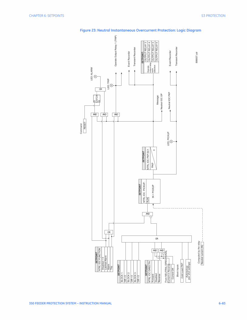
CHAPTER 6: SETPOINTS S3 PROTECTION
350 FEEDER PROTECTION SYSTEM – INSTRUCTION MANUAL 6–83
Figure 23: Neutral Instantaneous Overcurrent Protection: Logic Diagram
SE
TP
OIN
T
Neutr
alcurr
ent(I
N)
RU
N
SE
TP
OIN
T
BLO
CK
1:
Off
=0
NT
RL
IOC
PIC
KU
P:
IN>
PIC
KU
P
BLO
CK
2:
Off
=0
BLO
CK
3:
Off
=0
OR
AND
Opera
teO
utp
utR
ela
y1
(TR
IP)
EventR
ecord
er
Tra
nsie
ntR
ecord
er
LE
D:T
RIP
OR
OR
Cold
Load
PK
P
Auto
reclo
se
(per
shotsettin
gs)
Com
pute
dby
the
rela
y
Blo
ck
Inputs
AND
SE
TP
OIN
T:
Op
era
te
ou
tpu
tre
lay
up
on
se
lectio
n
OU
TP
UT
RE
LA
Y4
OU
TP
UT
RE
LA
Y5
OU
TP
UT
RE
LA
Y6
OU
TP
UT
RE
LA
Y3
AND
SE
TP
OIN
T
NT
RL
IOC
DIR
EC
TN
:
Forw
ard
Dis
able
d
Revers
e
SE
TP
OIN
T
NT
RL
IOC
FU
NC
TIO
N:
Dis
able
d=
0
Latc
hed
Ala
rm
Ala
rm
Trip
AND AND
Curr
entin
Revers
e
Fro
mN
EU
TR
AL
DIR
EC
TIO
NA
L
Curr
entO
K
NT
RL
IOC
PK
PD
LY
:
SE
TP
OIN
T
t PK
P0
EventR
ecord
er
Tra
nsie
ntR
ecord
er
LE
D:A
LA
RM
RE
SE
T
Com
mand
AND
S RLA
TC
H
LE
D:P
ICK
UP
Neutr
alIO
CP
KP
Message:
Neutr
alIO
CO
P
898007.c
dr
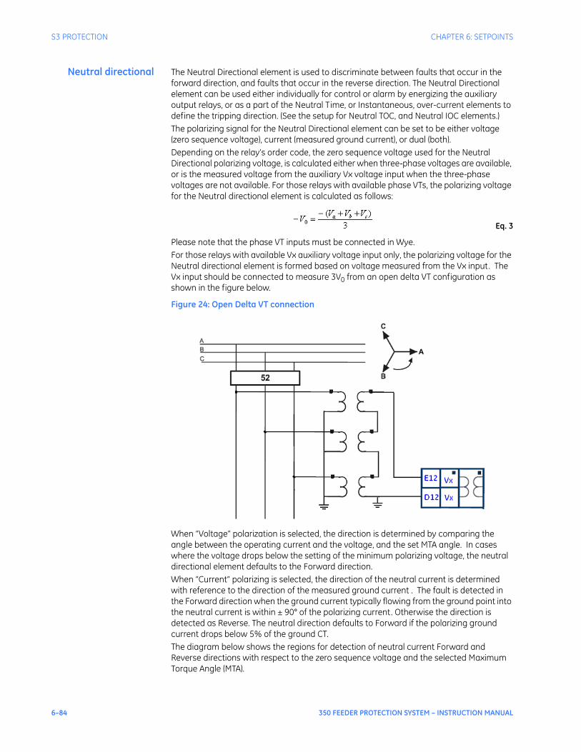
6–84 350 FEEDER PROTECTION SYSTEM – INSTRUCTION MANUAL
S3 PROTECTION CHAPTER 6: SETPOINTS
Neutral directional The Neutral Directional element is used to discriminate between faults that occur in the forward direction, and faults that occur in the reverse direction. The Neutral Directional element can be used either individually for control or alarm by energizing the auxiliary output relays, or as a part of the Neutral Time, or Instantaneous, over-current elements to define the tripping direction. (See the setup for Neutral TOC, and Neutral IOC elements.)The polarizing signal for the Neutral Directional element can be set to be either voltage (zero sequence voltage), current (measured ground current), or dual (both). Depending on the relay’s order code, the zero sequence voltage used for the Neutral Directional polarizing voltage, is calculated either when three-phase voltages are available, or is the measured voltage from the auxiliary Vx voltage input when the three-phase voltages are not available. For those relays with available phase VTs, the polarizing voltage for the Neutral directional element is calculated as follows:
Eq. 3
Please note that the phase VT inputs must be connected in Wye.For those relays with available Vx auxiliary voltage input only, the polarizing voltage for the Neutral directional element is formed based on voltage measured from the Vx input. The Vx input should be connected to measure 3V0 from an open delta VT configuration as shown in the figure below.
Figure 24: Open Delta VT connection
When “Voltage” polarization is selected, the direction is determined by comparing the angle between the operating current and the voltage, and the set MTA angle. In cases where the voltage drops below the setting of the minimum polarizing voltage, the neutral directional element defaults to the Forward direction.When “Current” polarizing is selected, the direction of the neutral current is determined with reference to the direction of the measured ground current . The fault is detected in the Forward direction when the ground current typically flowing from the ground point into the neutral current is within ± 90° of the polarizing current. Otherwise the direction is detected as Reverse. The neutral direction defaults to Forward if the polarizing ground current drops below 5% of the ground CT. The diagram below shows the regions for detection of neutral current Forward and Reverse directions with respect to the zero sequence voltage and the selected Maximum Torque Angle (MTA).
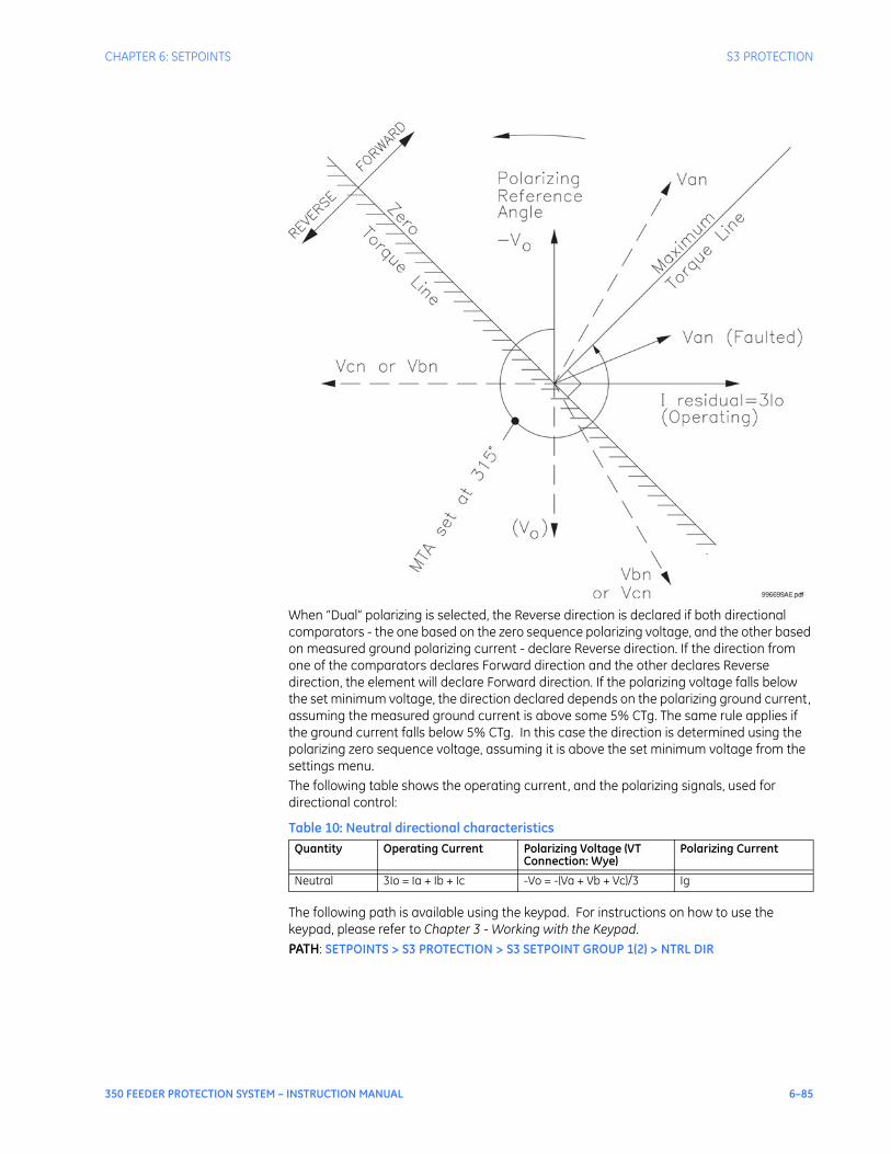
CHAPTER 6: SETPOINTS S3 PROTECTION
350 FEEDER PROTECTION SYSTEM – INSTRUCTION MANUAL 6–85
When “Dual” polarizing is selected, the Reverse direction is declared if both directional comparators - the one based on the zero sequence polarizing voltage, and the other based on measured ground polarizing current - declare Reverse direction. If the direction from one of the comparators declares Forward direction and the other declares Reverse direction, the element will declare Forward direction. If the polarizing voltage falls below the set minimum voltage, the direction declared depends on the polarizing ground current, assuming the measured ground current is above some 5% CTg. The same rule applies if the ground current falls below 5% CTg. In this case the direction is determined using the polarizing zero sequence voltage, assuming it is above the set minimum voltage from the settings menu.The following table shows the operating current, and the polarizing signals, used for directional control:
Table 10: Neutral directional characteristics
The following path is available using the keypad. For instructions on how to use the keypad, please refer to Chapter 3 - Working with the Keypad.PATH: SETPOINTS > S3 PROTECTION > S3 SETPOINT GROUP 1(2) > NTRL DIR
Quantity Operating Current Polarizing Voltage (VT Connection: Wye)
Polarizing Current
Neutral 3Io = Ia + Ib + Ic -Vo = -(Va + Vb + Vc)/3 Ig

6–86 350 FEEDER PROTECTION SYSTEM – INSTRUCTION MANUAL
S3 PROTECTION CHAPTER 6: SETPOINTS
NTRL DIR FUNCTION
Range: Disabled, Latched Alarm, Alarm, ControlDefault: Disabled
When an Alarm function is selected, the alarm LED will flash upon detection of Reverse direction, and will drop out when the direction changes to Forward. When Latched Alarm is selected, the alarm LED will flash upon detection of Reverse direction, and will stay lit (latched) after the direction changes to Forward. The alarm LED can be reset, by issuing a Reset command. Detection of Reverse direction when the Control function is selected, does not trigger the alarm LED.
NTRL DIR POLARIZING
Range: Voltage, Current, DualDefault: Voltage
This setting specifies the voltage polarizing signal for the detection of Forward and Reverse directions.
NTRL DIR MTA
Range: 0° to 359° Lead in steps of 1°Default: 315°
This setting sets the Maximum Torque Angle (MTA), for the Neutral Directional element to define the regions of Forward and Reverse directions. For Voltage polarizing, enter the maximum torque angle by which the operating current leads the polarizing voltage. This is the angle of maximum sensitivity.
MIN POL VOLTAGE
Range: 0.05 to 1.25 x VT in steps of 0.01Default: 0.05 x VT
This setting affects only cases where voltage or dual polarizing is selected. The minimum zero sequence voltage level must be selected to prevent operation due to normal system unbalances, or voltage transformer errors. Set the minimum zero sequence voltage level to 2% of VT for well balanced systems, and 1% of VT accuracy. For systems with high resistance grounding or floating neutrals, this setting can be as high as 20%. The default of 5% of VT is appropriate for most solidly grounded systems.
OUTPUT RELAY 3 to 6
Range: Do not operate, OperateDefault: Do not operate
Any or all of the output relays 3 to 6 can be selected to operate upon Neutral Directional operation. The selection of relay outputs operation is available no matter whether Latched Alarm, Alarm, or Trip function is selected.
BLOCK 1/2/3
Range: Off, Contact Input 1 to 10[8], Virtual Input 1 to 32, Remote Input 1 to 32, Logic Element 1 to 16Default: Off
Three blocking inputs are provided in the Neutral Directional menu. One blocking input going “high” is enough to block the function. The selection for each block can be Contact input, Virtual Input, Remote Input, or Logic Element.
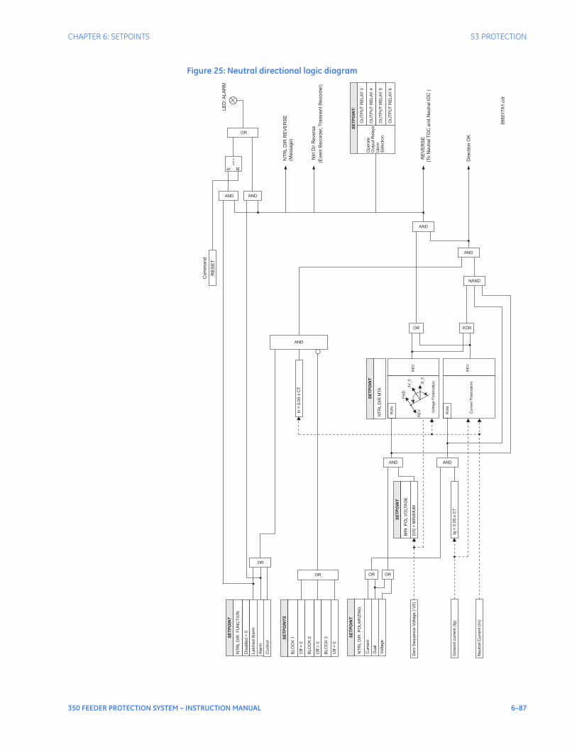
CHAPTER 6: SETPOINTS S3 PROTECTION
350 FEEDER PROTECTION SYSTEM – INSTRUCTION MANUAL 6–87
Figure 25: Neutral directional logic diagram
Zero
Sequence
Voltage
(-V
0)
SE
TP
OIN
T
NT
RL
DIR
FU
NC
TIO
N
Dis
able
d=
0
Latc
hed
Ala
rm
SE
TP
OIN
TS
BLO
CK
1
Off
=0
BLO
CK
2
Off
=0
BLO
CK
3
Off
=0
OR
NT
RL
DIR
RE
VE
RS
E
(To
Neutr
alT
OC
and
Neutr
alIO
C)
Ala
rm
OR
OR
RE
VE
RS
E
(Message)
AND
SE
TP
OIN
T:
Opera
te
Outp
utR
ela
ys
Upon
Sele
ction
OU
TP
UT
RE
LA
Y4
OU
TP
UT
RE
LA
Y5
OU
TP
UT
RE
LA
Y6
OU
TP
UT
RE
LA
Y3
Contr
ol
Neutr
alC
urr
ent(I
n)
Gro
und
curr
ent(I
g)
Voltage
Pola
rization
-3V
_0
3I_
0
FW
D
RE
V
RE
V
RU
N
SE
TP
OIN
T
NT
RL
DIR
MTA
Curr
ent
Pola
rization
RE
V
RU
N
SE
TP
OIN
T
NT
RL
DIR
PO
LA
RIZ
ING
:
Curr
ent
Dual
Voltage
OR OR
SE
TP
OIN
T
MIN
PO
LV
OLTA
GE
|V0|>
MIN
IMU
M
AND
Ig>
0.0
5x
CT
AND
In>
0.0
5x
CT
AND
OR XOR
AND
NAND
AND
Ntr
lD
irR
evers
e
(EventR
ecord
er,
Tra
nsie
ntR
ecord
er)
Direction
OK
LE
D:A
LA
RM
RE
SE
T
Com
mand
89
80
17
A1
.cd
r
AND
LA
TC
H
S R

6–88 350 FEEDER PROTECTION SYSTEM – INSTRUCTION MANUAL
S3 PROTECTION CHAPTER 6: SETPOINTS
Negative sequenceinstantaneous
overcurrentprotection
The 350 relay has one Negative Sequence Overcurrent element per protection group. The negative sequence over-current protection responds to negative sequence current, where it is calculated as .
The negative sequence over-current elements are uniquely suited to detect phase-phase faults and are not sensitive to balanced loads. While negative sequence elements do not respond to balanced load, they do detect the negative sequence current present in unbalanced load. For this reason, select an element pickup setting above the maximum expected current due to load unbalance.PATH: SETPOINTS > S3 PROTECTION > SETPOINT GROUP 1(2) > NEG SEQ IOC
NEG SEQ IOC FUNCTION
Range: Disabled, Latched Alarm, Alarm, TripDefault: Disabled
The selection of the Latched Alarm, Alarm, or Trip setting enables the Negative Sequence IOC function. The output relay #1 “Trip” will operate if the function Trip is selected, and the negative sequence current computed by the relay, is above the NEG SEQ IOC PKP setting for a time greater than the selected time under NEG SEQ IOC DELAY. The LED “ALARM” will not turn on if the neg. sequence IOC function is set to Trip. The LED “ALARM” will flash under the neg. sequence IOC operating condition, with the neg. sequence IOC function selected as Alarm, and will self-reset, when this operating condition clears. If Latched Alarm is selected as a neg. seq. IOC function, the LED “ALARM” will flash during the IOC condition, and will stay “ON” after the condition clears, until the reset command is initiated. The output relay #1 “Trip” will not operate if Latched Alarm or Alarm setting is selected. Any or all of the output relays 3 to 6 can be selected to operate with the neg. seq. IOC function selected as Latched Alarm, Alarm, or Trip.
NEG SEQ IOC PKP
Range: 0.05 to 20.00 x CT in steps of 0.01 x CTDefault: 1.00 x CT
This setting defines the negative sequence IOC pickup level.
NEG SEQ IOC DELAY
Range: 0.00 to 300.00 sec in steps of 0.01 secDefault: 0.00 sec
This setting specifies the time delay before IOC operation. .
OUTPUT RELAY 3 to 6
Range: Do not operate, OperateDefault: Do not operate
Any or all of the output relays 3 to 6 can be selected to operate upon a Neg Seq IOC condition. Relay outputs operation is available no matter whether the Latched Alarm, Alarm, or Trip function is selected.
BLOCK 1/2/3
Range: Off, Contact Input 1 to 10[8], Virtual Input 1 to 32, Remote Input 1 to 32, Logic Elements 1 to 16Default: Off
Three blocking inputs are provided in the Neg. seq. IOC menu. Any one of the assigned blocking inputs can block the function. The available selections for each block include Contact input, Virtual Input, Remote Input, or Logic Element.
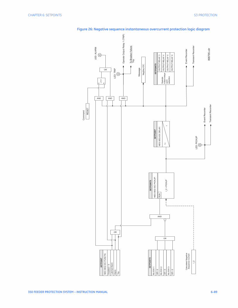
CHAPTER 6: SETPOINTS S3 PROTECTION
350 FEEDER PROTECTION SYSTEM – INSTRUCTION MANUAL 6–89
Figure 26: Negative sequence instantaneous overcurrent protection logic diagram
Calc
ula
ted
Negative
Sequence
Curr
ent
SE
TP
OIN
TS
SE
TP
OIN
T
NE
GS
EQ
IOC
FU
NC
TN
:
Dis
able
d=
0
Latc
hed
Ala
rm
NE
GS
EQ
IOC
PIC
KU
P:
AND
Opera
teO
utp
ut
Rela
y1
(TR
IP)
Eve
nt
Re
co
rde
r
Tra
nsie
nt
Re
co
rde
r
LE
D:T
RIP
Ala
rm
OR
OR
AND
SE
TP
OIN
TS
Opera
te
outp
utre
lays
upon
sele
ction
OU
TP
UT
RE
LA
Y4
OU
TP
UT
RE
LA
Y5
OU
TP
UT
RE
LA
Y6
OU
TP
UT
RE
LA
Y3
Trip
AND
To
Bre
ake
rF
ailu
re
Trip
SE
TP
OIN
TS
BL
OC
K1
:
Off
=0
BL
OC
K2
:
Off
=0
BL
OC
K3
:
Off
=0
OR
RU
N
LE
D:
PIC
KU
P
Eve
nt
Re
co
rde
r
Tra
nsie
nt
Re
co
rde
r
NegS
eq
IOC
Me
ssa
ge
I_2
>P
ICK
UP
NE
GS
EQ
IOC
DE
LA
Y:
SE
TP
OIN
T
t PK
P
I_2
LE
D:
ALA
RM
RE
SE
T
Co
mm
an
d
ANDS R
LA
TC
H
0
89
87
95
.cd
r
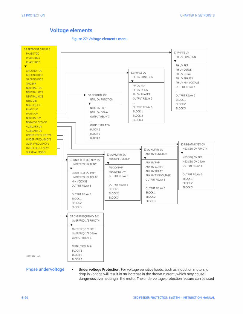
6–90 350 FEEDER PROTECTION SYSTEM – INSTRUCTION MANUAL
S3 PROTECTION CHAPTER 6: SETPOINTS
Voltage elementsFigure 27: Voltage elements menu
Phase undervoltage • Undervoltage Protection: For voltage sensitive loads, such as induction motors, a drop in voltage will result in an increase in the drawn current, which may cause dangerous overheating in the motor. The undervoltage protection feature can be used
S3 SETPOINT GROUP 1
PHASE TOC
PHASE IOC1
PHASE IOC2
GROUND
GND DIR
NEUTRAL TOC
NEUTRAL IOC1
NEUTRAL IOC2
NEG SEQ IOC
PHASE UV
PHASE OV
NEUTRAL OV
NEGATIVE SEQ OV
AUXILIARY UV
AUXILIARY OV
UNDER-FREQUENCY1
UNDER-FREQUENCY2
OVER-FREQUENCY1
OVER-FREQUENCY2
THERMAL MODEL
TOC
GROUND IOC1
GROUND IOC2
▼
NTRL DIR
S3 UNDERFREQUENCY 1/2
UNDRFREQ 1/2 FUNC
UNDRFREQ 1/2 PKP
UNDRFREQ 1/2 DELAY
MIN VOLTAGE
OUTPUT RELAY 3
...
OUTPUT RELAY 6
BLOCK 1
BLOCK 2
BLOCK 3
▼
S3 AUXILIARY OV
AUX OV FUNCTION
AUX OV PKP
AUX OV DELAY
OUTPUT RELAY 3
...
OUTPUT RELAY 6
BLOCK 1
BLOCK 2
BLOCK 3
▼
S3 AUXILIARY UV
AUX UV FUNCTION
PKP
DELAY
OUTPUT RELAY 3
...
OUTPUT RELAY 6
BLOCK 1
BLOCK 2
BLOCK 3
AUX UV
AUX UV CURVE
AUX UV
AUX UV MIN VOLTAGE
▼
S3 NEGATIVE SEQ OV
NEG SEQ OV FUNCTN
PKP
DELAY
OUTPUT RELAY 3
...
OUTPUT RELAY 6
BLOCK 1
BLOCK 2
BLOCK 3
NEG SEQ OV
NEG SEQ OV
▼
S3 OVERFREQUENCY 1/2
OVERFREQ 1/2 FUNCTN
OVERFREQ 1/2 PKP
OVERFREQ 1/2 DELAY
OUTPUT RELAY 3
...
OUTPUT RELAY 6
BLOCK 1
BLOCK 2
BLOCK 3
▼
S3 NEUTRAL OV
NTRL OV FUNCTION
PKP
DELAY
OUTPUT RELAY 3
...
OUTPUT RELAY 6
BLOCK 1
BLOCK 2
BLOCK 3
NTRL OV
NTRL OV
▼
S3 PHASE OV
PH OV FUNCTION
PKP
DELAY
PH OV PHASES
OUTPUT RELAY 3
...
OUTPUT RELAY 6
BLOCK 1
BLOCK 2
BLOCK 3
PH OV
PH OV
▼
S3 PHASE UV
PH UV FUNCTION
PKP
PH UV CURVE
DELAY
PH UV PHASES
PH UV MIN VOLTAGE
OUTPUT RELAY 3
...
OUTPUT RELAY 6
BLOCK 1
BLOCK 2
BLOCK 3
PH UV
PH UV
▼
898759A1.cdr
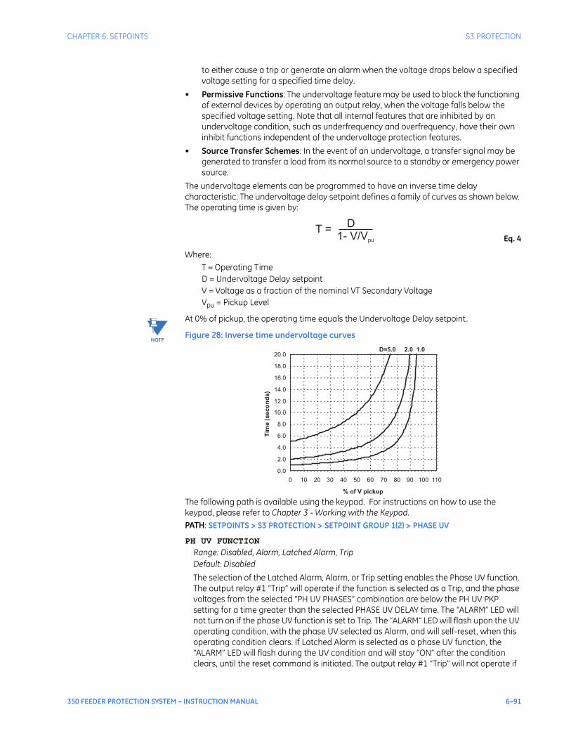
CHAPTER 6: SETPOINTS S3 PROTECTION
350 FEEDER PROTECTION SYSTEM – INSTRUCTION MANUAL 6–91
to either cause a trip or generate an alarm when the voltage drops below a specified voltage setting for a specified time delay.
• Permissive Functions: The undervoltage feature may be used to block the functioning of external devices by operating an output relay, when the voltage falls below the specified voltage setting. Note that all internal features that are inhibited by an undervoltage condition, such as underfrequency and overfrequency, have their own inhibit functions independent of the undervoltage protection features.
• Source Transfer Schemes: In the event of an undervoltage, a transfer signal may be generated to transfer a load from its normal source to a standby or emergency power source.
The undervoltage elements can be programmed to have an inverse time delay characteristic. The undervoltage delay setpoint defines a family of curves as shown below. The operating time is given by:
Eq. 4
Where: T = Operating TimeD = Undervoltage Delay setpointV = Voltage as a fraction of the nominal VT Secondary VoltageVpu = Pickup Level
NOTE
NOTE: At 0% of pickup, the operating time equals the Undervoltage Delay setpoint.
Figure 28: Inverse time undervoltage curves
The following path is available using the keypad. For instructions on how to use the keypad, please refer to Chapter 3 - Working with the Keypad.PATH: SETPOINTS > S3 PROTECTION > SETPOINT GROUP 1(2) > PHASE UV
PH UV FUNCTION
Range: Disabled, Alarm, Latched Alarm, TripDefault: Disabled
The selection of the Latched Alarm, Alarm, or Trip setting enables the Phase UV function. The output relay #1 “Trip” will operate if the function is selected as a Trip, and the phase voltages from the selected “PH UV PHASES” combination are below the PH UV PKP setting for a time greater than the selected PHASE UV DELAY time. The “ALARM” LED will not turn on if the phase UV function is set to Trip. The “ALARM” LED will flash upon the UV operating condition, with the phase UV selected as Alarm, and will self-reset, when this operating condition clears. If Latched Alarm is selected as a phase UV function, the “ALARM” LED will flash during the UV condition and will stay “ON” after the condition clears, until the reset command is initiated. The output relay #1 “Trip” will not operate if
T =D
1- V/Vpu
D=5.0 2.0 1.0
0.0
2.0
4.0
6.0
8.0
10.0
12.0
14.0
16.0
18.0
20.0
0 10 20 30 40 50 60 70 80 90 100 110
% of V pickup
Tim
e(s
eco
nd
s)
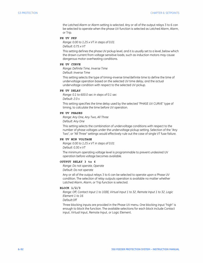
6–92 350 FEEDER PROTECTION SYSTEM – INSTRUCTION MANUAL
S3 PROTECTION CHAPTER 6: SETPOINTS
the Latched Alarm or Alarm setting is selected. Any or all of the output relays 3 to 6 can be selected to operate when the phase UV function is selected as Latched Alarm, Alarm, or Trip.
PH UV PKP
Range: 0.00 to 1.25 x VT in steps of 0.01Default: 0.75 x VT
This setting defines the phase UV pickup level, and it is usually set to a level, below which the drawn current from voltage sensitive loads, such as induction motors may cause dangerous motor overheating conditions.
PH UV CURVE
Range: Definite Time, Inverse TimeDefault: Inverse Time
This setting selects the type of timing-inverse time/definite time to define the time of undervoltage operation based on the selected UV time delay, and the actual undervoltage condition with respect to the selected UV pickup.
PH UV DELAY
Range: 0.1 to 600.0 sec in steps of 0.1 secDefault: 2.0 s
This setting specifies the time delay used by the selected “PHASE UV CURVE” type of timing, to calculate the time before UV operation.
PH UV PHASES
Range: Any One, Any Two, All ThreeDefault: Any One
This setting selects the combination of undervoltage conditions with respect to the number of phase voltages under the undervoltage pickup setting. Selection of the “Any Two”, or “All Three” settings would effectively rule out the case of single VT fuse failure.
PH UV MIN VOLTAGE
Range: 0.00 to 1.25 x VT in steps of 0.01Default: 0.30 x VT
The minimum operating voltage level is programmable to prevent undesired UV operation before voltage becomes available.
OUTPUT RELAY 3 to 6
Range: Do not operate, OperateDefault: Do not operate
Any or all of the output relays 3 to 6 can be selected to operate upon a Phase UV condition. The selection of relay outputs operation is available no matter whether Latched Alarm, Alarm, or Trip function is selected.
BLOCK 1/2/3
Range: Off, Contact Input 1 to 10[8], Virtual Input 1 to 32, Remote Input 1 to 32, Logic Element 1 to 16Default:Off
Three blocking inputs are provided in the Phase UV menu. One blocking input “high” is enough to block the function. The available selections for each block include Contact input, Virtual Input, Remote Input, or Logic Element.
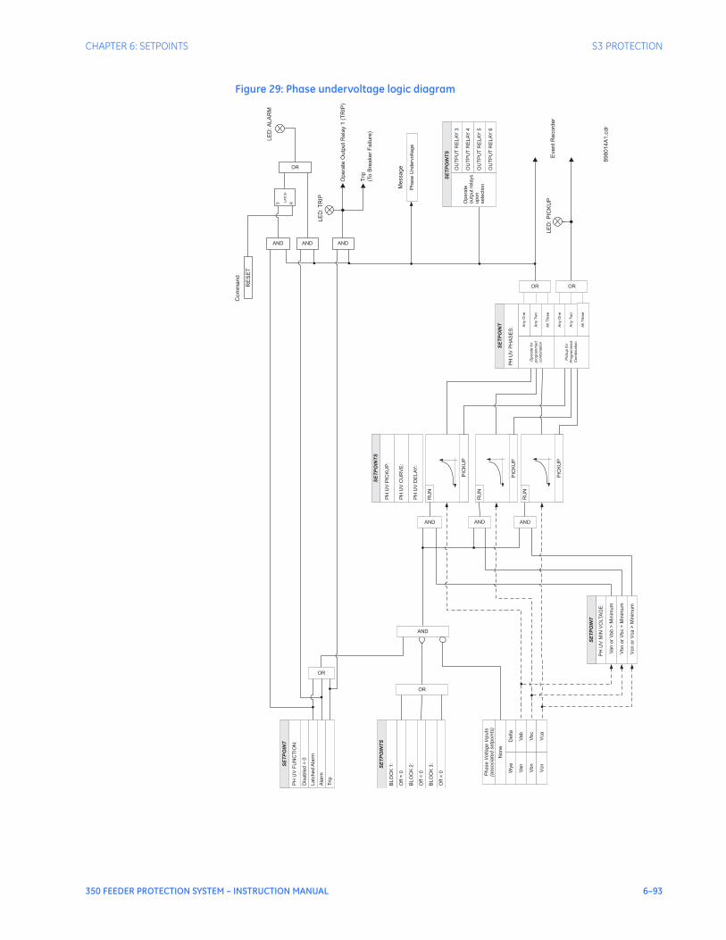
CHAPTER 6: SETPOINTS S3 PROTECTION
350 FEEDER PROTECTION SYSTEM – INSTRUCTION MANUAL 6–93
Figure 29: Phase undervoltage logic diagram
Phase
Voltage
Inputs
(associa
ted
setp
oin
ts)
SE
TP
OIN
TS
Vab
SE
TP
OIN
T
PH
UV
FU
NC
TIO
N:
Dis
able
d=
0
Latc
hed
Ala
rm
PH
UV
PIC
KU
P:
PH
UV
CU
RV
E:
PH
UV
DE
LA
Y:
AND
Vbc
Vca
Op
era
teO
utp
utR
ela
y1
(TR
IP)
Eve
ntR
eco
rde
r
LE
D:T
RIP
Ala
rm
OR
OR
AND
SE
TP
OIN
TS
Opera
te
outp
utre
lays
upon
sele
ction
OU
TP
UT
RE
LA
Y4
OU
TP
UT
RE
LA
Y5
OU
TP
UT
RE
LA
Y6
OU
TP
UT
RE
LA
Y3
Trip
AND
Trip
(To
Bre
ake
rF
ailu
re)
SE
TP
OIN
TS
BLO
CK
1:
Off
=0
BLO
CK
2:
Off
=0
BLO
CK
3:
Off
=0
OR
RU
N
RU
N
RU
N
PIC
KU
P
Van
Vbn
Vcn
None
PIC
KU
P
PIC
KU
P
Van
or
Vab
>M
inim
um
Vbn
or
Vbc
>M
inim
um
Vcn
or
Vca
>M
inim
um
PH
UV
MIN
VO
LTA
GE
:
SE
TP
OIN
T
AND AND AND
Delta
Wye
All
Thre
e
Any
One
Any
Tw
o
Opera
tefo
r
pro
gra
mm
ed
com
bin
ation
Any
Tw
o
Any
One
All
Thre
e
Pic
kup
for
Pro
gra
mm
ed
Com
bin
ation
SE
TP
OIN
T
PH
UV
PH
AS
ES
:
OR OR
LE
D:P
ICK
UP
Phase
Underv
oltage
Me
ssa
ge
LE
D:A
LA
RM
RE
SE
T
Com
mand
AND
S R
LA
TC
H
89
80
14
A1
.cd
r

6–94 350 FEEDER PROTECTION SYSTEM – INSTRUCTION MANUAL
S3 PROTECTION CHAPTER 6: SETPOINTS
Phase overvoltage The phase OV protection can be used to protect voltage sensitive feeder loads and circuits against sustained overvoltage conditions. The protection can be used to either cause a trip, or generate an alarm when the voltage exceeds a specified voltage value for the specified time delay.The following path is available using the keypad. For instructions on how to use the keypad, please refer to Chapter 3 - Working with the Keypad.PATH: SETPOINTS > S3 PROTECTION > SETPOINT GROUP 1(2) > PHASE OV
PH OV FUNCTION
Range: Disabled, Alarm, Latched Alarm, TripDefault: Disabled
The selection of the Latched Alarm, Alarm, or Trip setting enables the Phase OV function. The output relay #1 “Trip” will operate, if the function is selected as a Trip, and the phase voltages from the selected “PH OV PHASES” combination are above the PH OV PKP setting for a time greater than the selected PHASE OV DELAY time. The “ALARM” LED will not turn on if the phase OV function is set to Trip. The “ALARM” LED will flash upon the OV operating condition, with the phase OV selected as Alarm, and will self-reset, when this operating condition clears. If Latched Alarm is selected as a phase OV function, the “ALARM” LED will flash during the OV condition and will stay “ON” after the condition clears, until the reset command is initiated. The output relay #1 “Trip” will not operate if the Latched Alarm or Alarm setting is selected. Any or all of the output relays 3 to 6 can be selected to operate when the phase OV function is selected as Latched Alarm, Alarm, or Trip.
PH OV PKP
Range: 0.00 to 1.25 x VT in steps of 0.01Default: 1.25 x VT
This setting defines the phase OV pickup level, and it is usually set to a level above which some voltage sensitive loads and feeder components may experience overexcitation and dangerous overheating conditions.
PH OV DELAY
Range: 0.1 to 600.0 sec in steps of 0.1Default: 2.0 s
This setting specifies the time delay before OV operation.
PH OV PHASES
Range: Any One, Any Two, All ThreeDefault: Any One
This setting selects the combination of overvoltage conditions with respect to the number of phase voltages over the overvoltage pickup setting.
OUTPUT RELAY 3 to 6
Range: Do not operate, OperateDefault: Do not operate
Any or all of the output relays 3 to 6 can be selected to operate upon a Phase OV condition. The selection of relay outputs operation is available no matter whether Latched Alarm, Alarm, or Trip function is selected.
BLOCK 1/2/3
Range: Off, Contact Input 1 to 10[8], Virtual Input 1 to 32, Remote Input 1 to 32, Logic Element 1 to 16Default: Off
Three blocking inputs are provided in the Phase OV menu. One blocking input “high” is enough to block the function. The available selections for each block include Contact input, Virtual Input, Remote Input, or Logic Element.
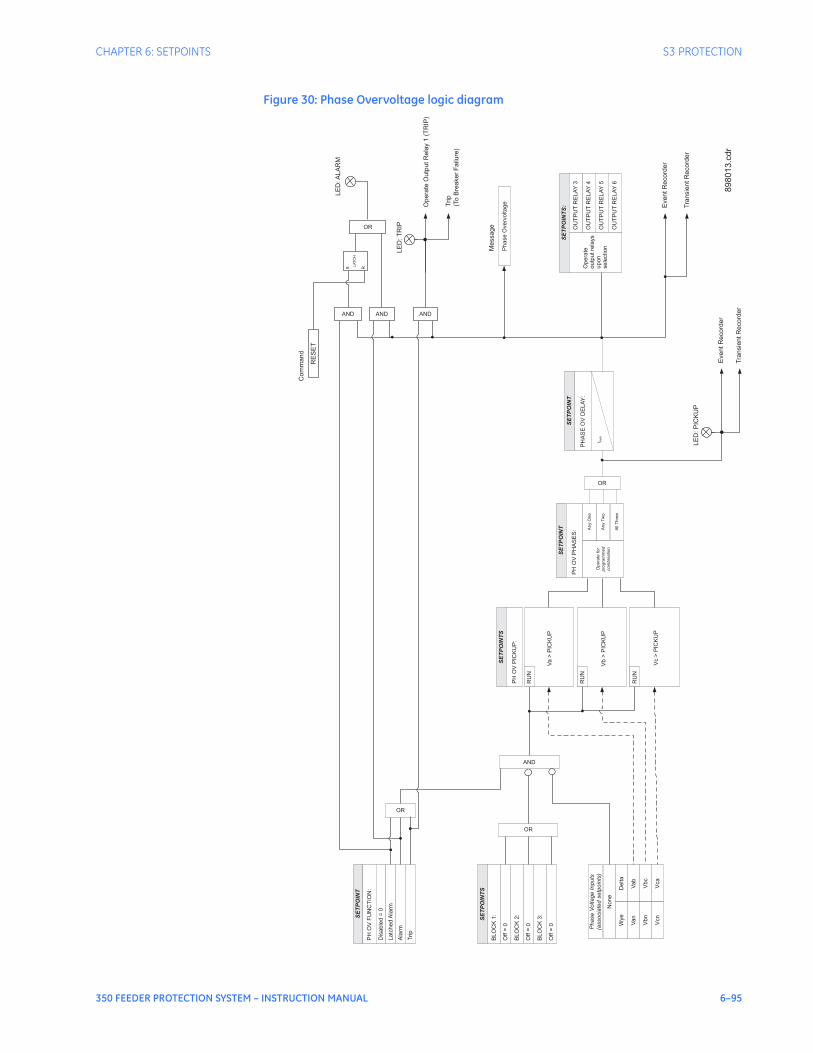
CHAPTER 6: SETPOINTS S3 PROTECTION
350 FEEDER PROTECTION SYSTEM – INSTRUCTION MANUAL 6–95
Figure 30: Phase Overvoltage logic diagram
Phase
Voltage
Inputs
(associa
ted
setp
oin
ts)
SE
TP
OIN
TS
Vab
SE
TP
OIN
T
PH
OV
FU
NC
TIO
N:
Dis
able
d=
0
Latc
hed
Ala
rm
PH
OV
PIC
KU
P:
AND
Vbc
Vca
Opera
teO
utp
utR
ela
y1
(TR
IP)
EventR
ecord
er
Tra
nsie
ntR
ecord
er
LE
D:T
RIP
Ala
rm
OR
OR
AND
SE
TP
OIN
TS
:
Opera
te
outp
ut
rela
ys
upon
sele
ction
OU
TP
UT
RE
LA
Y4
OU
TP
UT
RE
LA
Y5
OU
TP
UT
RE
LA
Y6
OU
TP
UT
RE
LA
Y3
Trip
AND
Trip
(To
Bre
aker
Failure
)
SE
TP
OIN
TS
BLO
CK
1:
Off
=0
BLO
CK
2:
Off
=0
BLO
CK
3:
Off
=0
OR
RU
N
RU
N
RU
NV
an
Vbn
Vcn
None
Delta
Wye
LE
D:P
ICK
UP
EventR
ecord
er
Tra
nsie
ntR
ecord
er
Phase
Overv
oltage
Message
Va
>P
ICK
UP
Vb
>P
ICK
UP
Vc
>P
ICK
UP
All
Thre
e
Opera
tefo
r
pro
gra
mm
ed
com
bin
ation
Any
Tw
o
Any
One
SE
TP
OIN
T
PH
OV
PH
AS
ES
:
OR
PH
AS
EO
VD
ELA
Y:
SE
TP
OIN
T
t PK
P
LE
D:A
LA
RM
RE
SE
T
Com
mand
AND
S R
LA
TC
H
89
80
13
.cd
r

6–96 350 FEEDER PROTECTION SYSTEM – INSTRUCTION MANUAL
S3 PROTECTION CHAPTER 6: SETPOINTS
Neutral overvoltage The relay has one Neutral Overvoltage element per protection group. This element requires the three phase Bus VTs to be Wye connected. When setting the pickup for this element, it is important to consider the error in the VT ratio, as well as the normal voltage unbalance on the system.
NOTE
NOTE: This element should be used with caution. It would normally be applied to give line to ground fault coverage on high impedance grounded or ungrounded systems, which are isolated. This constraint stems from the fact that a measurement of 3V0 cannot discriminate between a faulted circuit and an adjacent healthy circuit. Use of a time delayed back-up or an alarm mode allow other protections an opportunity to isolate the faulted element first.
The following path is available using the keypad. For instructions on how to use the keypad, please refer to Chapter 3 - Working with the Keypad.PATH: SETPOINTS > S3 PROTECTION > SETPOINT GROUP 1(2) > NEUTRAL OV
NEUTRAL OV FUNCTION
Range: Disabled, Alarm, Latched Alarm,TripDefault: Disabled
The selection of the Latched Alarm, Alarm, or Trip setting enables the Neutral OV function. The output relay #1 “Trip” will operate if the function is selected as a Trip and the neutral voltage is above the NTRL OV PKP setting for a time greater than the selected NTRL OV DELAY time. The “ALARM” LED will not turn on if the neutral OV function is set to Trip. The “ALARM” LED will flash upon an OV operating condition, with the neutral OV function selected as Alarm, and will self-reset, when this operating condition clears. If Latched Alarm is selected as a neutral OV function, the “ALARM” LED will flash during the OV condition, and will stay “ON” after the condition clears, until the reset command is initiated. The output relay #1 “Trip” will not operate if the Latched Alarm or Alarm setting is selected. Any or all of the output relays 3 to 6 can be selected to operate when the neutral OV function is selected as Latched Alarm, Alarm, or Trip.
NEUTRAL OV PKP
Range: 0.00 to 1.25 x VT in steps of 0.01Default: 0.30 x VT
This setting defines the neutral OV pickup level.
NEUTRAL OV DELAY
Range: 0.1 to 600.0 sec in steps of 0.1 secDefault: 2.0 s
This setting specifies the time delay before OV operation.
OUTPUT RELAY 3 to 6
Range: Do not operate, OperateDefault: Do not operate
Any or all of the output relays 3 to 6 can be selected to operate upon a Neutral OV condition. The selection of relay outputs operation is available no matter whether Latched Alarm, Alarm, or Trip function is selected.
BLOCK 1/2/3
Range: Off, Contact Input 1 to 10[8], Virtual Input 1 to 32, Remote Input 1 to 32, Logic Element 1 to 16Default: Off
Three blocking inputs are provided in the Neutral OV menu. One blocking input “high” is enough to block the function. The available selections for each block include Contact input, Virtual Input, Remote Input, or Logic Element.
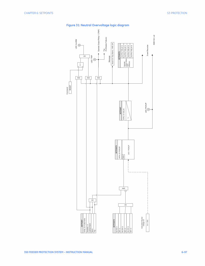
CHAPTER 6: SETPOINTS S3 PROTECTION
350 FEEDER PROTECTION SYSTEM – INSTRUCTION MANUAL 6–97
Figure 31: Neutral Overvoltage logic diagram
Ca
lcu
late
dN
eu
tra
l
Vo
lta
ge
V0
SE
TP
OIN
TS
SE
TP
OIN
T
NT
RL
OV
FU
NC
TIO
N:
Dis
ab
led
=0
La
tch
ed
Ala
rm
NT
RL
OV
PIC
KU
P:
AND
Opera
teO
utp
utR
ela
y1
(TR
IP)
EventR
ecord
er
LE
D:T
RIP
Ala
rm
OR
OR
AND
SE
TP
OIN
TS
:
Op
era
te
ou
tpu
tre
lays
up
on
se
lectio
n
OU
TP
UT
RE
LA
Y4
OU
TP
UT
RE
LA
Y5
OU
TP
UT
RE
LA
Y6
OU
TP
UT
RE
LA
Y3
Trip
AND
Trip
(To
Bre
aker
Failure
)
SE
TP
OIN
TS
BL
OC
K1
:
Off
=0
BL
OC
K2
:
Off
=0
BL
OC
K3
:
Off
=0
OR
RU
N
Vn
=3
V0
LE
D:P
ICK
UP
Ne
utr
lO
VT
rip
(Ala
rm)
-P
KP,
OP
Message
3V
0>
PIC
KU
P
NT
RL
OV
DE
LA
Y:
SE
TP
OIN
T
t PK
P
LE
D:A
LA
RM
RE
SE
T
Com
mand
ANDS R
LA
TC
H
89
80
15
A1
.cd
r

6–98 350 FEEDER PROTECTION SYSTEM – INSTRUCTION MANUAL
S3 PROTECTION CHAPTER 6: SETPOINTS
Negative sequenceovervoltage
The relay has one Negative Sequence Overvoltage element per protection group. The negative sequence overvoltage may be used to detect the loss of one or two phases of the source, a reversed voltage phase sequence , or non-system voltage conditions.The following path is available using the keypad. For instructions on how to use the keypad, please refer to Chapter 3 - Working with the Keypad.PATH: SETPOINTS > S3 PROTECTION > SETPOINT GROUP 1(2) > NEGATIVE SEQ. OV
NEG SEQ OV FUNCTION
Range: Disabled, Alarm, Latched Alarm, TripDefault: Disabled
The selection of the Latched Alarm, Alarm, or Trip setting enables the Negative Sequence OV function. The output relay #1 “Trip” will operate, if the function is selected as a Trip and the negative sequence voltage computed by the relay is above the NEG SEQ OV PKP setting for a time greater than the selected NEG SEQ OV DELAY time. The “ALARM” LED will not turn on, if the neg. sequence OV function is set to Trip. The “ALARM” LED will flash upon an OV operating condition with the neg. sequence OV function selected as Alarm, and will self-reset, when the operating condition clears. If Latched Alarm is selected as a neg. seq. OV function, the “ALARM” LED will flash during the OV condition, and will stay “ON” after the condition clears, until the reset command is initiated. The output relay #1 “Trip” will not operate if the Latched Alarm or Alarm setting is selected. Any or all of the output relays 3 to 6 can be selected to operate when the neg. seq. OV function is selected as Latched Alarm, Alarm, or Trip.
NEG SEQ OV PKP
Range: 0.00 to 1.25 x VT in steps of 0.01Default: 0.30 x VT
This setting defines the negative sequence OV pickup level.
NEG SEQ OV DELAY
Range: 0.1 to 600.0 sec in steps of 0.1 secDefault: 2.0 s
This setting specifies the time delay before OV operation.
OUTPUT RELAY 3 to 6
Range: Do not operate, OperateDefault: Do not operate
Any or all of the output relays 3 to 6 can be selected to operate upon a Negative Seq. OV condition. The selection of relay outputs operation is available no matter whether Latched Alarm, Alarm, or Trip function is selected.
BLOCK 1/2/3
Range: Off, Contact Input 1 to 10[8], Virtual Input 1 to 32, Remote Input 1 to 32, Logic Element 1 to 16Default: Off
Three blocking inputs are provided in the Neg. Seq. OV menu. One blocking input “high” is enough to block the function. The available selections for each block include Contact input, Virtual Input, Remote Input, or Logic Element.
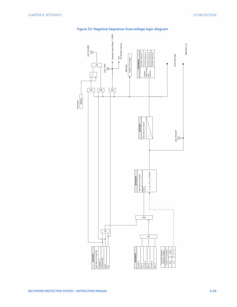
CHAPTER 6: SETPOINTS S3 PROTECTION
350 FEEDER PROTECTION SYSTEM – INSTRUCTION MANUAL 6–99
Figure 32: Negative Sequence Overvoltage logic diagram
Ca
lcu
late
dN
eg
ative
Se
qu
en
ce
Vo
lta
ge
SE
TP
OIN
TS
SE
TP
OIN
T
NE
GS
EQ
OV
FU
NC
TN
:
Dis
ab
led
=0
La
tch
ed
Ala
rm
NE
GS
EQ
OV
PIC
KU
P:
AND
Opera
teO
utp
utR
ela
y1
(TR
IP)
Event
Record
er
LE
D:T
RIP
Ala
rm
OR
OR
AND
SE
TP
OIN
TS
:
Op
era
te
ou
tpu
tre
lays
up
on
se
lectio
n
OU
TP
UT
RE
LA
Y4
OU
TP
UT
RE
LA
Y5
OU
TP
UT
RE
LA
Y6
OU
TP
UT
RE
LA
Y3
Trip
AND
Trip
(To
Bre
aker
Failure
)
SE
TP
OIN
TS
BL
OC
K1
:
Off
=0
BL
OC
K2
:
Off
=0
BL
OC
K3
:
Off
=0
OR
RU
N
V_
2
Ph
ase
VT
co
nn
ectio
n
Delta
Wye
LE
D:P
ICK
UP
Ne
gS
eq
Ove
rvo
lta
ge
Message
V_
2o
r�
�*V
_2
>P
ICK
UP
NE
GS
EQ
OV
DE
LA
Y:
SE
TP
OIN
T
t PK
P
�3
*V
_2
LE
D:A
LA
RM
RE
SE
T
Com
mand
ANDS R
LA
TC
H
89
80
16
A1
.cd
r
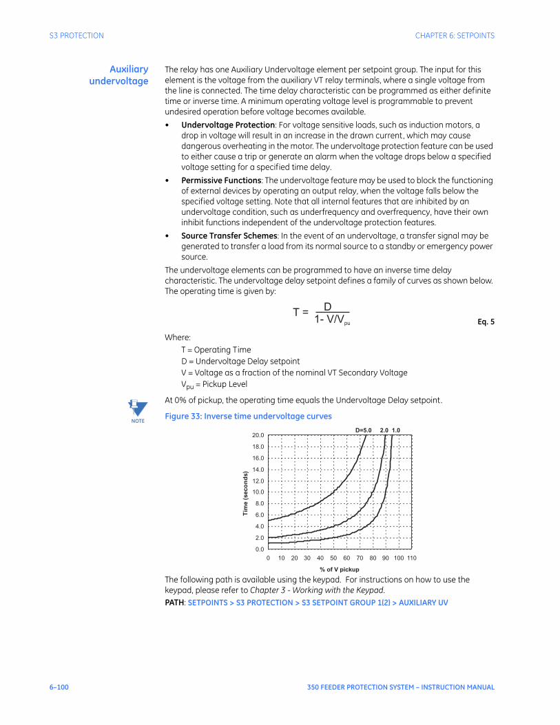
6–100 350 FEEDER PROTECTION SYSTEM – INSTRUCTION MANUAL
S3 PROTECTION CHAPTER 6: SETPOINTS
Auxiliaryundervoltage
The relay has one Auxiliary Undervoltage element per setpoint group. The input for this element is the voltage from the auxiliary VT relay terminals, where a single voltage from the line is connected. The time delay characteristic can be programmed as either definite time or inverse time. A minimum operating voltage level is programmable to prevent undesired operation before voltage becomes available.• Undervoltage Protection: For voltage sensitive loads, such as induction motors, a
drop in voltage will result in an increase in the drawn current, which may cause dangerous overheating in the motor. The undervoltage protection feature can be used to either cause a trip or generate an alarm when the voltage drops below a specified voltage setting for a specified time delay.
• Permissive Functions: The undervoltage feature may be used to block the functioning of external devices by operating an output relay, when the voltage falls below the specified voltage setting. Note that all internal features that are inhibited by an undervoltage condition, such as underfrequency and overfrequency, have their own inhibit functions independent of the undervoltage protection features.
• Source Transfer Schemes: In the event of an undervoltage, a transfer signal may be generated to transfer a load from its normal source to a standby or emergency power source.
The undervoltage elements can be programmed to have an inverse time delay characteristic. The undervoltage delay setpoint defines a family of curves as shown below. The operating time is given by:
Eq. 5
Where: T = Operating TimeD = Undervoltage Delay setpointV = Voltage as a fraction of the nominal VT Secondary VoltageVpu = Pickup Level
NOTE
NOTE: At 0% of pickup, the operating time equals the Undervoltage Delay setpoint.
Figure 33: Inverse time undervoltage curves
The following path is available using the keypad. For instructions on how to use the keypad, please refer to Chapter 3 - Working with the Keypad.PATH: SETPOINTS > S3 PROTECTION > S3 SETPOINT GROUP 1(2) > AUXILIARY UV
T =D
1- V/Vpu
D=5.0 2.0 1.0
0.0
2.0
4.0
6.0
8.0
10.0
12.0
14.0
16.0
18.0
20.0
0 10 20 30 40 50 60 70 80 90 100 110
% of V pickup
Tim
e(s
eco
nd
s)

CHAPTER 6: SETPOINTS S3 PROTECTION
350 FEEDER PROTECTION SYSTEM – INSTRUCTION MANUAL 6–101
AUX UV FUNCTION
Range: Disabled, Alarm, Latched Alarm, TripDefault: Disabled
The selection of the Latched Alarm, Alarm, or Trip setting enables the Auxiliary UV function. The output relay #1 “Trip” will operate if the function is selected as a Trip, and the auxiliary voltage is below the AUX UV PKP setting for a time greater than the selected AUX UV DELAY time. The “ALARM" LED will not turn on if the auxiliary UV function is set to Trip. The “ALARM" LED will flash upon UV operation, with the aux. UV function selected as Alarm, and will self-reset when UV operation clears. If Latched Alarm is selected as a aux. UV function, the “ALARM" LED will flash during the UV condition, and will stay “ON” after the condition clears, until the reset command is initiated. The output relay #1 “Trip” will not operate if the Latched Alarm or Alarm setting is selected. Any or all of the output relays 3 to 6 can be selected to operate when the auxiliary UV function is selected as Latched Alarm, Alarm, or Trip.
AUX UV PKP
Range: 0.00 to 1.25 x VT in steps of 0,01Default: 0.75 x VT
This setting defines the auxiliary UV pickup level.
AUX UV CURVE
Range: Definite Time, Inverse TimeDefault: Inverse Time
This setting selects the type of timing-inverse time/definite time, to define the time of aux. undervoltage operation based on selected UV time delay, and the actual undervoltage condition with respect to the selected UV pickup.
AUX UV DELAY
Range: 0.1 to 600.0 sec in steps of 0.1 secDefault: 2.0 s
This setting specifies a time delay used by the selected “AUX UV CURVE” type of timing to calculate the time before UV operation.
AUX UV MIN VOLTAGE
Range: 0.00 to 1.25 x VT in steps of 0,01Default: 0.30 x VT
The minimum operating voltage level is programmable to prevent undesired UV operation before voltage becomes available.
OUTUT RELAY 3 to 6
Range: Do not operate, OperateDefault: Do not operate
Any or all of the output relays 3 to 6 can be selected to operate upon an Auxiliary UV condition. The selection of relay outputs operation is available no matter whether Latched Alarm, Alarm, or Trip function is selected.
BLOCK 1/2/3
Range: Off, Contact Input 1 to 10[8], Virtual Input 1 to 32, Remote Input 1 to 32, Logic Element 1 to 16Default: Off
Three blocking inputs are provided in the Auxiliary UV menu. One blocking input “high” is enough to block the function. The available selections for each block include Contact input, Virtual Input, Remote Input, or Logic Element.
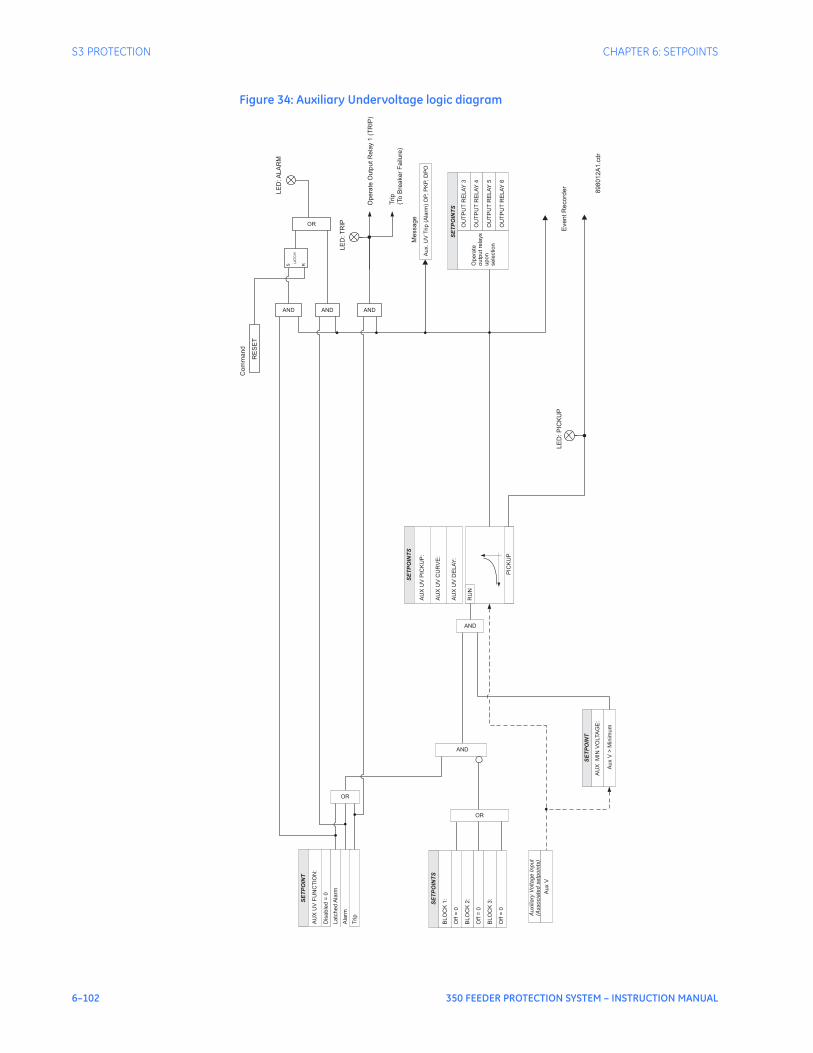
6–102 350 FEEDER PROTECTION SYSTEM – INSTRUCTION MANUAL
S3 PROTECTION CHAPTER 6: SETPOINTS
Figure 34: Auxiliary Undervoltage logic diagram
Au
xilia
ryV
olta
ge
Inp
ut
(Asso
cia
ted
se
tpo
ints
)
SE
TP
OIN
TS
SE
TP
OIN
T
AU
XU
VF
UN
CT
ION
:
Dis
ab
led
=0
La
tch
ed
Ala
rm
AU
XU
VP
ICK
UP
:
AU
XU
VC
UR
VE
:
AU
XU
VD
EL
AY
:
AND
Opera
teO
utp
utR
ela
y1
(TR
IP)
EventR
ecord
er
LE
D:T
RIP
Ala
rm
OR
OR
AND
SE
TP
OIN
TS
Op
era
te
ou
tpu
tre
lays
up
on
se
lectio
n
OU
TP
UT
RE
LA
Y4
OU
TP
UT
RE
LA
Y5
OU
TP
UT
RE
LA
Y6
OU
TP
UT
RE
LA
Y3
Trip
AND
Trip
(To
Bre
aker
Failure
)
SE
TP
OIN
TS
BL
OC
K1
:
Off
=0
BL
OC
K2
:
Off
=0
BL
OC
K3
:
Off
=0
OR
RU
N
PIC
KU
P
Au
xV
>M
inim
um
AU
XM
INV
OLTA
GE
:
SE
TP
OIN
T
AND
LE
D:P
ICK
UP
Au
x.
UV
Trip
(Ala
rm)
OP,
PK
P,
DP
O
Message
LE
D:A
LA
RM
RE
SE
T
Com
mand
AND
S R
LA
TC
H
89
80
12
A1
.cd
r
Au
xV

CHAPTER 6: SETPOINTS S3 PROTECTION
350 FEEDER PROTECTION SYSTEM – INSTRUCTION MANUAL 6–103
Auxiliary overvoltage The relay has one Auxiliary Overvoltage element per protection group. The element is intended for monitoring overvoltage conditions of the auxiliary voltage input. A typical application for this element is monitoring the zero sequence voltage (3V_0) from an open corner Delta VT connection. The nominal voltage for the auxiliary voltage input is set under Setpoints > S2 System Setup > Voltage Sensing > Aux VT Secondary.The following path is available using the keypad. For instructions on how to use the keypad, please refer to Chapter 3 - Working with the Keypad.PATH: SETPOINTS > S3 PROTECTION > SETPOINT GROUP 1(2) > AUXILIARY OV
AUX OV FUNCTION
Range: Disabled, Alarm, Latched Alarm, TripDefault: Disabled
The selection of Latched Alarm, Alarm, or Trip setting enables the Auxiliary OV function. The output relay #1 “Trip” will operate, if the function is selected as a Trip, and the auxiliary voltage is above the AUX OV PKP setting for a time greater than the selected AUX OV DELAY time. The “ALARM” LED will not turn on, if the auxiliary OV function is set to Trip. The LED “ALARM” will flash upon an OV operating condition, with the aux. OV function selected as Alarm, and will self-reset, when the operating condition clears. If Latched Alarm is selected as an aux. OV function, the “ALARM” LED will flash during the OV condition, and will stay “ON” after the condition clears until the reset command is initiated. The output relay #1 “Trip” will not operate if the Latched Alarm or Alarm setting is selected. Any or all of output relays 3 to 6 can be selected to operate when the auxiliary OV function is selected as Latched Alarm, Alarm, or Trip.
AUX OV PKP
Range: 0.00 to 1.25 x VT in steps of 0.01Default: 1.25 x VT
This setting defines the auxiliary OV pickup level.
AUX OV DELAY
Range: 0.1 to 600.0 sec in steps of 0.1Default: 2.0 s
This setting specifies the time delay before OV operation.
OUTPUT RELAY 3 to 6
Range: Do not operate, OperateDefault: Do not operate
Any or all of the output relays 3 to 6 can be selected to operate upon an Auxiliary OV condition. The selection of relay outputs operation is available no matter whether Latched Alarm, Alarm, or Trip function is selected.
BLOCK 1/2/3
Range: Off, Contact Input 1 to 10[8], Virtual Input 1 to 32, Remote Input 1 to 32, Logic Element 1 to 16Default: Off
Three blocking inputs are provided in the Auxiliary OV menu. One blocking input “high” is enough to block the function. The available selections for each block include Contact input, Virtual Input, Remote Input, or Logic Element.
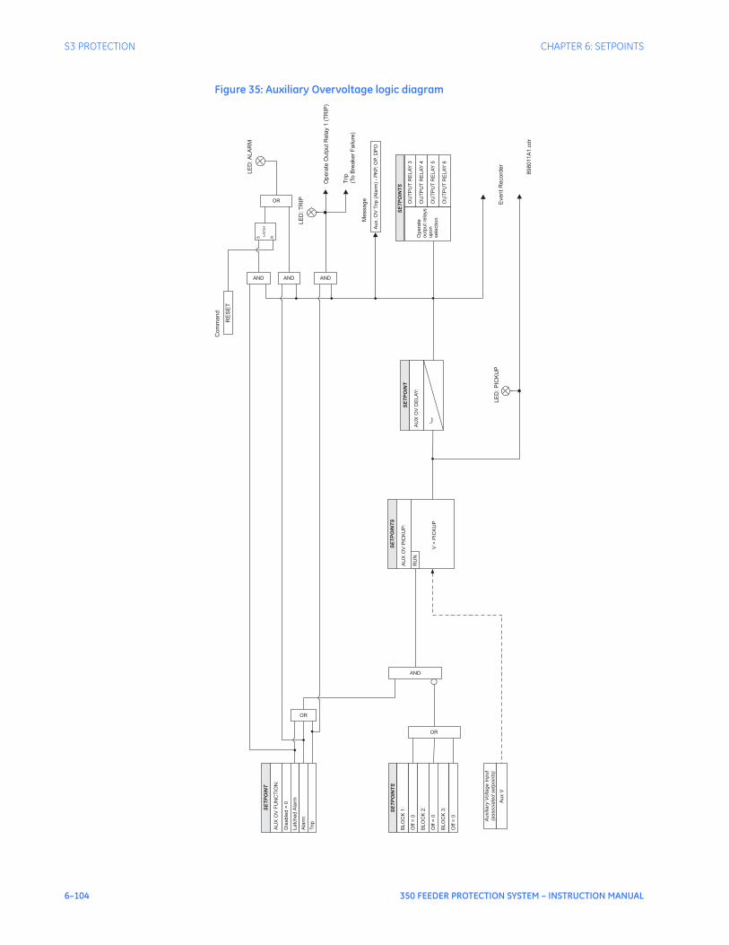
6–104 350 FEEDER PROTECTION SYSTEM – INSTRUCTION MANUAL
S3 PROTECTION CHAPTER 6: SETPOINTS
Figure 35: Auxiliary Overvoltage logic diagram
Auxilia
ryV
oltage
Input
(associa
ted
setp
oin
ts)
SE
TP
OIN
TS
SE
TP
OIN
T
AU
XO
VF
UN
CT
ION
:
Dis
able
d=
0
Latc
hed
Ala
rm
AU
XO
VP
ICK
UP
:
AND
Opera
teO
utp
utR
ela
y1
(TR
IP)
EventR
ecord
er
LE
D:T
RIP
Ala
rm
OR
OR
AND
SE
TP
OIN
TS
Opera
te
outp
utre
lays
upon
sele
ction
OU
TP
UT
RE
LA
Y4
OU
TP
UT
RE
LA
Y5
OU
TP
UT
RE
LA
Y6
OU
TP
UT
RE
LA
Y3
Trip
AND
Trip
(To
Bre
aker
Failure
)
SE
TP
OIN
TS
BLO
CK
1:
Off
=0
BLO
CK
2:
Off
=0
BLO
CK
3:
Off
=0
OR
RU
N
Aux
V
LE
D:P
ICK
UP
Aux.O
VT
rip
(Ala
rm)
-P
KP,O
P,D
PO
Message
V>
PIC
KU
P
AU
XO
VD
ELA
Y:
SE
TP
OIN
T
t PK
P
LE
D:A
LA
RM
RE
SE
T
Com
mand
AND
S R
LA
TC
H
898011A
1.c
dr

CHAPTER 6: SETPOINTS S3 PROTECTION
350 FEEDER PROTECTION SYSTEM – INSTRUCTION MANUAL 6–105
Underfrequency The relay is equipped with two Underfrequency elements per setpoint group. These elements can be used for detecting system underfrequency conditions, and be part of an automatic load shedding scheme. The need for such protection arises if during a system disturbance, an area becomes electrically isolated from the main system and suffers a generation deficiency due to the loss of either transmission or generation facilities. If reserve generation is not available in the area, conditions of low frequency will occur and may lead to a complete collapse. The 350 provides two underfrequency elements, which can automatically disconnect sufficient load to restore an acceptable balance between load and generation.The following path is available using the keypad. For instructions on how to use the keypad, please refer to Chapter 3 - Working with the Keypad.PATH: SETPOINTS > S3 PROTECTION > PROTECTION GROUP 1(2) > UNDER-FREQUENCY1(2)
UNDERFREQ 1(2) FUNCTION
Range: Disabled, Alarm, Latched Alarm, TripDefault: Disabled
The selection of Latched Alarm, Alarm, or Trip setting enables the Underfrequency function. The output relay #1 “Trip” will operate, if the function is selected as a Trip, and the measured frequency is below the UNDERFREQ PKP setting for a time longer than the selected UNDERFREQ DELAY time. The LED “ALARM” will not turn on, if the Underfrequency function is set to Trip. The LED “ALARM” will flash upon underfrequency operating condition, with the underfreq. function selected as Alarm, and will self-reset, when the operating condition clears. If Latched Alarm is selected, the LED “ALARM” will flash during the underfrequency condition, and will stay “ON” after the condition clears, until reset command is initiated. The output relay #1 “Trip” will not operate if Latched Alarm or Alarm setting is selected. Any or all of the output relays 3 to 6 can be selected to operate when the Underfrequency function is selected as Latched Alarm, Alarm, or Trip.
UNDERFREQ 1(2) PKP
Range: 40.00 to 70.00 Hz in steps of 0.01 HzDefault: 59.00 Hz
This setting defines the Underfrequency pickup level, and it is usually set to a frequency level considered dangerous for the stability of the system.
UNDERFREQ 1(2) DELAY
Range: 0.1 to 600.0 sec in steps of 0.1 secDefault: 2.0 s
This setting specifies the time delay before underfrequency operation.
MIN VOLTAGE
Range: 0.00 to 1.25 x VT in steps of 0.01 Default: 0.70 x VT
The minimum operating voltage level is programmable to prevent undesired underfrequency operation before voltage becomes available, such as on faults cleared by downstream protection or fuses.
OUTPUT RELAY 3 to 6
Range: Do not operate, OperateDefault: Do not operate
Any or all of the output relays 3 to 6 can be selected to operate upon an Underfrequency condition. The selection of relay outputs operation is available no matter whether Latched Alarm, Alarm, or Trip function is selected.

6–106 350 FEEDER PROTECTION SYSTEM – INSTRUCTION MANUAL
S3 PROTECTION CHAPTER 6: SETPOINTS
BLOCK 1/2/3
Range: Off, Contact Input 1 to 10[8], Virtual Input 1 to 32, Remote Input 1 to 32, Logic Element 1 to 16Default: Off
Three blocking inputs are provided in the menu for each of the two Underfrequency elelements. One blocking input “high” is enough to block the function. The available selections for each block include Contact input, Virtual Input, Remote Input, or Logic Element.
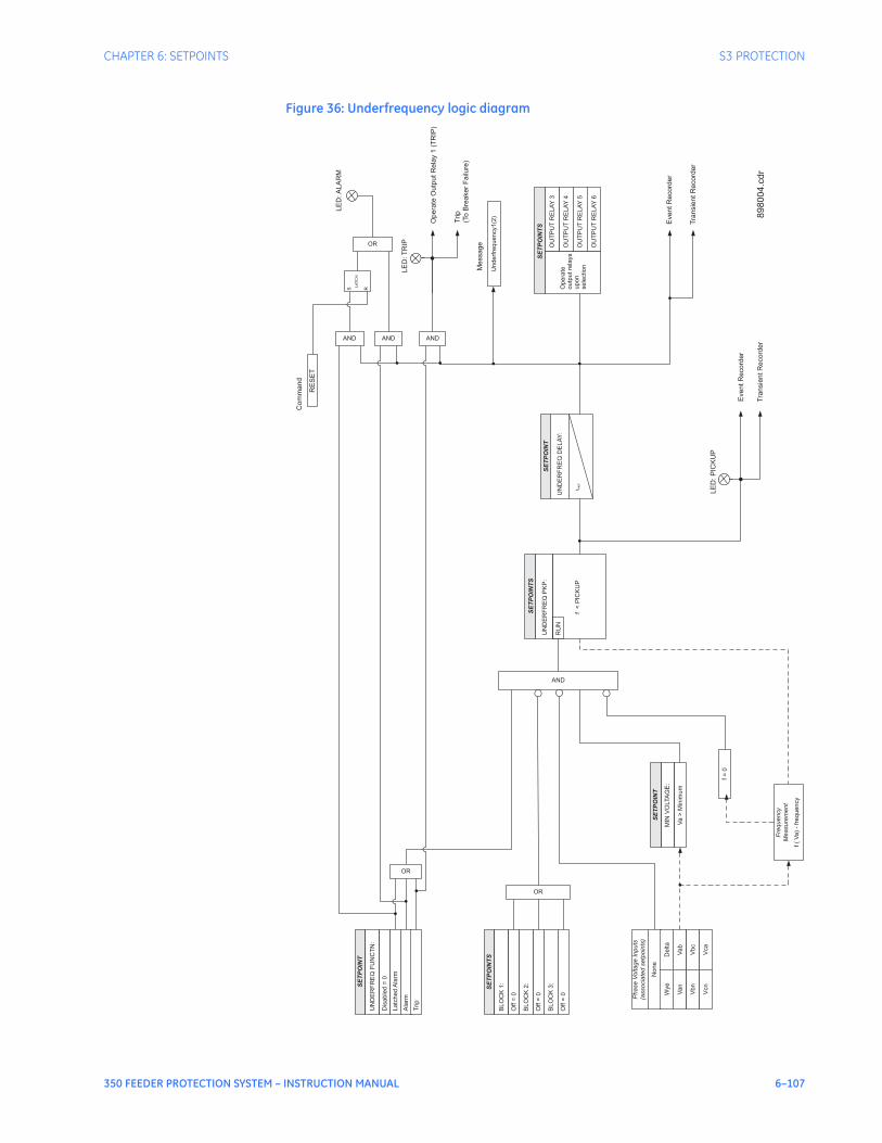
CHAPTER 6: SETPOINTS S3 PROTECTION
350 FEEDER PROTECTION SYSTEM – INSTRUCTION MANUAL 6–107
Figure 36: Underfrequency logic diagram
Ph
ase
Vo
lta
ge
Inp
uts
(asso
cia
ted
se
tpo
ints
)
SE
TP
OIN
TS
Va
b
SE
TP
OIN
T
UN
DE
RF
RE
QF
UN
CT
N:
Dis
ab
led
=0
La
tch
ed
Ala
rm
UN
DE
RF
RE
QP
KP
:
Vb
c
Vca
Opera
teO
utp
utR
ela
y1
(TR
IP)
EventR
ecord
er
Tra
nsie
ntR
ecord
er
LE
D:T
RIP
Ala
rm
OR
OR
AND
SE
TP
OIN
TS
Op
era
te
ou
tpu
tre
lays
up
on
se
lectio
n
OU
TP
UT
RE
LA
Y4
OU
TP
UT
RE
LA
Y5
OU
TP
UT
RE
LA
Y6
OU
TP
UT
RE
LA
Y3
Trip
AND
Trip
(To
Bre
aker
Failure
)
SE
TP
OIN
TS
BL
OC
K1
:
Off
=0
BL
OC
K2
:
Off
=0
BL
OC
K3
:
Off
=0
OR
RU
N
Va
n
Vb
n
Vcn
No
ne
AND
De
lta
Wye
LE
D:P
ICK
UP
EventR
ecord
er
Tra
nsie
ntR
ecord
er
Un
de
rfre
qu
en
cy1
(2)
Message
f<
PIC
KU
P
Fre
qu
en
cy
Me
asu
rem
en
t
f(
Va
)-
fre
qu
en
cy
Va
>M
inim
um
MIN
VO
LTA
GE
:
SE
TP
OIN
T
f=
0
UN
DE
RF
RE
QD
EL
AY
:
SE
TP
OIN
T
t PK
P
LE
D:A
LA
RM
RE
SE
T
Com
mand
AND
S R
LA
TC
H
898004.c
dr

6–108 350 FEEDER PROTECTION SYSTEM – INSTRUCTION MANUAL
S3 PROTECTION CHAPTER 6: SETPOINTS
Overfrequency The relay is equipped with two Overfrequency elements per setpoint group, ANSI device number 81O-1, and 81O-2. Voltage channel phase A is used for frequency measurement.The steady-state frequency of a power system is an indicator of the existing balance between generated power and the load. Whenever this power is disrupted through disconnection of significant load or the isolation of a part of the system that has surplus of generation, it would result in increase of frequency. If the control system of the generators do not respond fast enough to quickly ramp the turbine frequency back to normal, the overspeed can lead to turbine trip. The overfrequency elements can be used to control the turbine frequency at a generating location. This element can also be used for feeder reclosing as part of the “after load shedding restoration”The following path is available using the keypad. For instructions on how to use the keypad, please refer to Chapter 3 - Working with the Keypad.PATH: SETPOINTS > S3 PROTECTION > SETPOINT GROUP 1(2) > OVER-FREQUENCY1(2)
OVERFREQ 1(2) FUNCTION
Range: Disabled, Alarm, Latched Alarm, TripDefault: Disabled
The selection of the Latched Alarm, Alarm, or Trip setting enables the Overfrequency function. The output relay #1 “Trip” will operate, if the function is selected as a Trip, and the measured frequency is above the OVERFREQ PKP setting for a time longer than the selected OVERFREQ DELAY time. The “ALARM” LED will not turn on if the Overfrequency function is set to Trip. The “ALARM” LED will flash upon Overfrequency operating condition, with the overfrequency function selected as Alarm, and will self-reset, when the operating condition clears. If Latched Alarm is selected, the “ALARM” LED will flash during the overfrequency condition, and will stay “ON” after the condition clears until reset command is initiated. The output relay #1 “Trip” will not operate if the Latched Alarm or Alarm setting is selected. Any or all of output relays 3 to 6 can be selected to operate when the Overfrequency function is selected as Latched Alarm, Alarm, or Trip.
OVERFREQ 1(2) PKP
Range: 40.00 to 70.00 Hz in steps of 0.01Default: 60.50 Hz
This setting defines the Overfrequency pickup level, and it is usually set to a frequency level considered dangerous for the stability of the system.
OVERFREQ 1(2) DELAY
Range: 0.1 to 600.0 s in steps of 0.1Default: 2.0 s
This setting specifies the time delay before overfrequency operation.
OUTPUT RELAY 3 to 6
Range: Do Not Operate, OperateDefault: Do Not Operate
Any or all of output relays 3 to 6 can be selected to operate upon an Overfrequency condition. The selection of relay outputs operation is available no matter whether the Latched Alarm, Alarm, or Trip function is selected.
BLOCK 1/2/3 Range: Off, Contact Input 1 to 10[8], Virtual Input 1 to 32, Remote Input 1 to 32, Logic Element 1 to 16Default: Off
Three blocking inputs are provided in the menu for each of the two Overfrequency elements. One blocking input “high” is enough to block the function. The available selections for each block include Contact input, Virtual Input, Remote Input, or Logic Element.
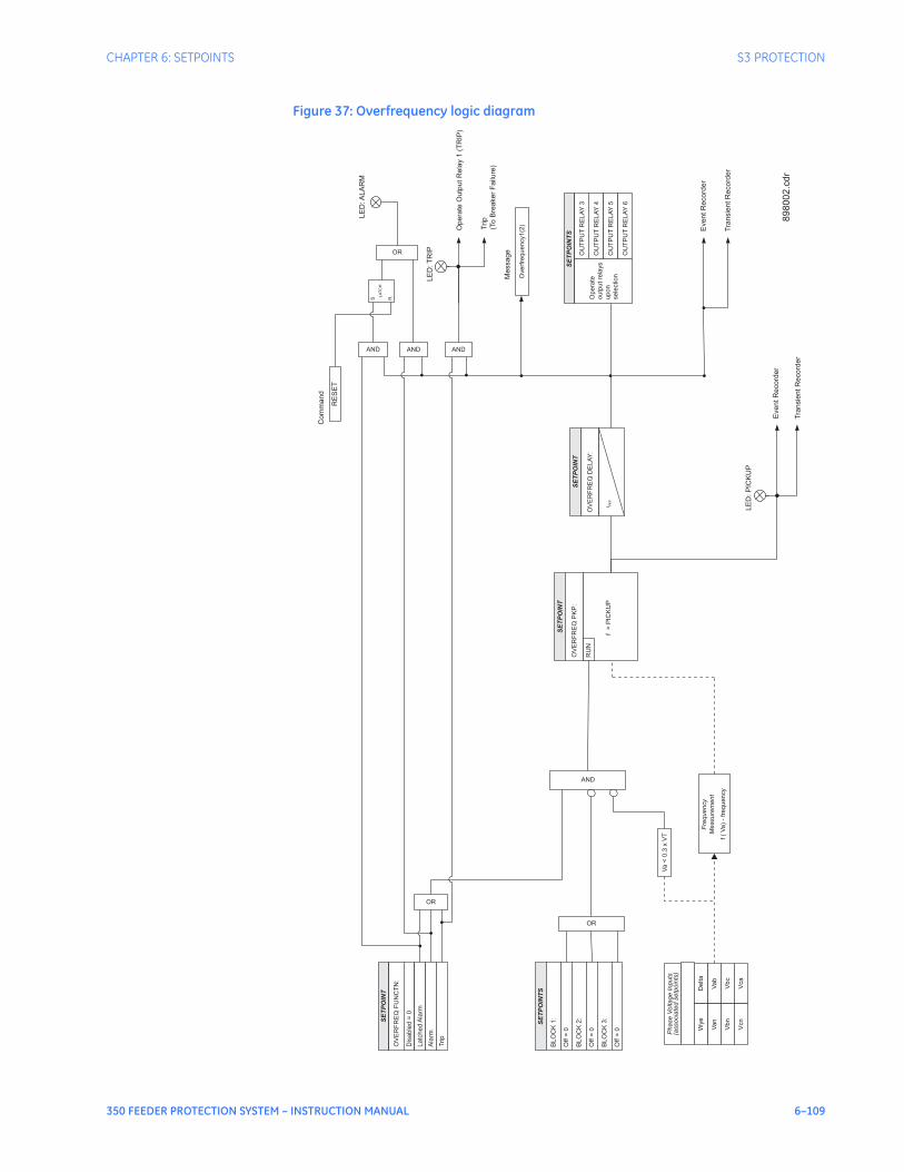
CHAPTER 6: SETPOINTS S3 PROTECTION
350 FEEDER PROTECTION SYSTEM – INSTRUCTION MANUAL 6–109
Figure 37: Overfrequency logic diagram
Phase
Voltage
Inputs
(associa
ted
setp
oin
ts)
SE
TP
OIN
T
Vab
SE
TP
OIN
T
OV
ER
FR
EQ
FU
NC
TN
:
Dis
able
d=
0
Latc
hed
Ala
rm
OV
ER
FR
EQ
PK
P:
Vbc
Vca
Opera
teO
utp
utR
ela
y1
(TR
IP)
EventR
ecord
er
Tra
nsie
ntR
ecord
er
LE
D:T
RIP
Ala
rm
OR
OR
AND
SE
TP
OIN
TS
Opera
te
outp
utre
lays
upon
sele
ction
OU
TP
UT
RE
LA
Y4
OU
TP
UT
RE
LA
Y5
OU
TP
UT
RE
LA
Y6
OU
TP
UT
RE
LA
Y3
Trip
AND
Trip
(To
Bre
aker
Failure
)
SE
TP
OIN
TS
BLO
CK
1:
Off
=0
BLO
CK
2:
Off
=0
BLO
CK
3:
Off
=0
OR
RU
N
Van
Vbn
Vcn
AND
Delta
Wye
LE
D:P
ICK
UP
EventR
ecord
er
Tra
nsie
ntR
ecord
er
Overf
requency1(2
)
Message
f>
PIC
KU
P
Fre
quency
Measure
ment
f(
Va)
-fr
equency
OV
ER
FR
EQ
DE
LA
Y:
SE
TP
OIN
T
t PK
P
LE
D:A
LA
RM
RE
SE
T
Com
mand
AND
S R
LA
TC
H
89
80
02
.cd
r
Va
<0.3
xV
T
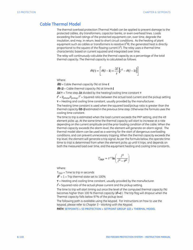
6–110 350 FEEDER PROTECTION SYSTEM – INSTRUCTION MANUAL
S3 PROTECTION CHAPTER 6: SETPOINTS
Cable Thermal ModelThe thermal overload protection (Thermal Model) can be applied to prevent damage to the protected cables, dry transformers, capacitor banks, or even overhead lines. Loads exceeding the load ratings of the protected equipment can, over time, degrade the insulation, and may, in return, lead to short circuit conditions. As the heating of plant equipment such as cables or transformers is resistive (I2R), the generated heat is directly proportional to the square of the flowing current (I2). The relay uses a thermal time characteristic based on current squared and integrated over time. The relay will continuously calculate the thermal capacity as a percentage of the total thermal capacity. The thermal capacity is calculated as follows:
Where:θ(t) = Cable thermal capacity (%) at time tθ(t-1) = Cable thermal capacity (%) at time t-1Δt/τ = Time step Δt divided by the heating/cooling time constant τI2 = (Iphase/Ipickup )2 = Squared ratio between the actual load current and the pickup settingτ = Heating and cooling time constant, usually provided by the manufacturer.The heating time constant is used when the squared load/pickup ratio is greater than the thermal capacity θ(t-1) estimated in the previous time step. Otherwise the formula uses the cooling time constant. The time to trip is estimated when the load current exceeds the PKP setting, and the 49 element picks up. At the same time the thermal capacity will start to increase at a rate depending on the current amplitude and the prior loading condition of the cable. When the thermal capacity exceeds the alarm level, the element will generate an alarm signal. The thermal model alarm can be used as a warning for the start of dangerous overloading conditions, and can prevent unnecessary tripping. When the thermal capacity exceeds the trip level, the element will generate a trip signal. As per the formula below, the operate time (time to trip) is determined from when the element picks up until it trips, and depends on both the measured load over time, and the equipment heating and cooling time constants.
Where:TTRIP = Time to trip in secondsθ2 = 1 = Trip thermal state set to 100%τ = Heating and cooling time constant, usually provided by the manufacturer.I2= Squared ratio of the actual phase current and the pickup setting.The time to trip will start timing out once the level of the computed thermal capacity (%) becomes higher than 100 % thermal capacity (θ =1 ). The trip flag will dropout when the Thermal capacity falls below 97% of the pickup level. The following path is available using the keypad. For instructions on how to use the keypad, please refer to Chapter 3 - Working with the Keypad.PATH: SETPOINTS > S3 PROTECTION > SETPOINT GROUP 1(2) > THERMAL MODEL

CHAPTER 6: SETPOINTS S3 PROTECTION
350 FEEDER PROTECTION SYSTEM – INSTRUCTION MANUAL 6–111
THERMAL MDL FUNC
Range: Disabled, Latched Alarm, Alarm, TripDefault: Disabled
The thermal capacity will be displayed on the relay even if the Thermal Model Function is set to “Disabled. The output relay #1 “Trip” will operate only if the function is selected as a Trip and the thermal capacity value of any phase is over 100%. The LED “ALARM” will turn on when the function is selected as a Trip or Alarm if the thermal capacity value of any phase is over the Thermal MDL Alarm setting. This LED will turn off when the thermal capacity value of all phases is below 97% of the Thermal MDL Alarm setting. If Latched Alarm is selected as a function setting, the LED “ALARM” will flash if the thermal capacity value of any phase is over the Thermal MDL Alarm setting, and will stay “ON” when the thermal capacity value of all phases is below 97% of the Thermal MDL Alarm setting, until the reset command is initiated. The output relay #1 “Trip” will not operate if the Latched Alarm or Alarm setting is selected. Any of the output relays 3 to 6 can be selected to operate when the Thermal Model Function is selected as Latched Alarm, Alarm or Trip. The thermal capacity values are stored in memory and can be cleared either by using the "Clear Thermal Capacity" command, or by cycling relay control power.
THERMAL MDL PKP
Range: 0.05 to 20 x CT in steps of 0.01 x CTDefault: 1.00 x CT
This setting sets the level of phase current above which the thermal model starts timing out the time-to-trip per the logarithmic formula above.
THERMAL MDL ALARM
Range: 70.0 to 110.0% in steps of 0.1%Default: 80.0%
This setting sets the alarm level for the accumulated thermal capacity above which the element generates an alarm.
HEAT TIME CONSTANT (τH)Range: 3.0 to 600.0 min in steps of 0.1 minDefault: 6.0 min
This time constant is used to compute the thermal capacity when the thermal capacity at each time-step is greater than the one computed in the previous time-step.
COOL TIME CONSTANT (τC)Range: 1.00 to 6.00 x τH in steps of 0.01 x τHDefault: 2.00 x τH
This time constant is used to compute the thermal capacity when the thermal capacity at each time-step is less than the one computed in the previous time-step.
OUTPUT RELAY 3 to 6
Range: Do Not Operate, OperateDefault: Do Not Operate
Any or all of output relays 3 to 6 can be selected to operate upon a Thermal Model condition. The selection of relay outputs operation is available no matter whether the Latched Alarm, Alarm, or Trip function is selected.

6–112 350 FEEDER PROTECTION SYSTEM – INSTRUCTION MANUAL
S3 PROTECTION CHAPTER 6: SETPOINTS
BLOCK 1/2/3
Range: Off, Contact Input 1 to 10[8], Virtual Input 1 to 32, Remote Input 1 to 32, Logic Element 1 to 16Default: Off
Three blocking inputs are provided in the menu. One blocking input “high” is enough to block the function. The available selections for each block include Contact input, Virtual Input, Remote Input, or Logic Element.
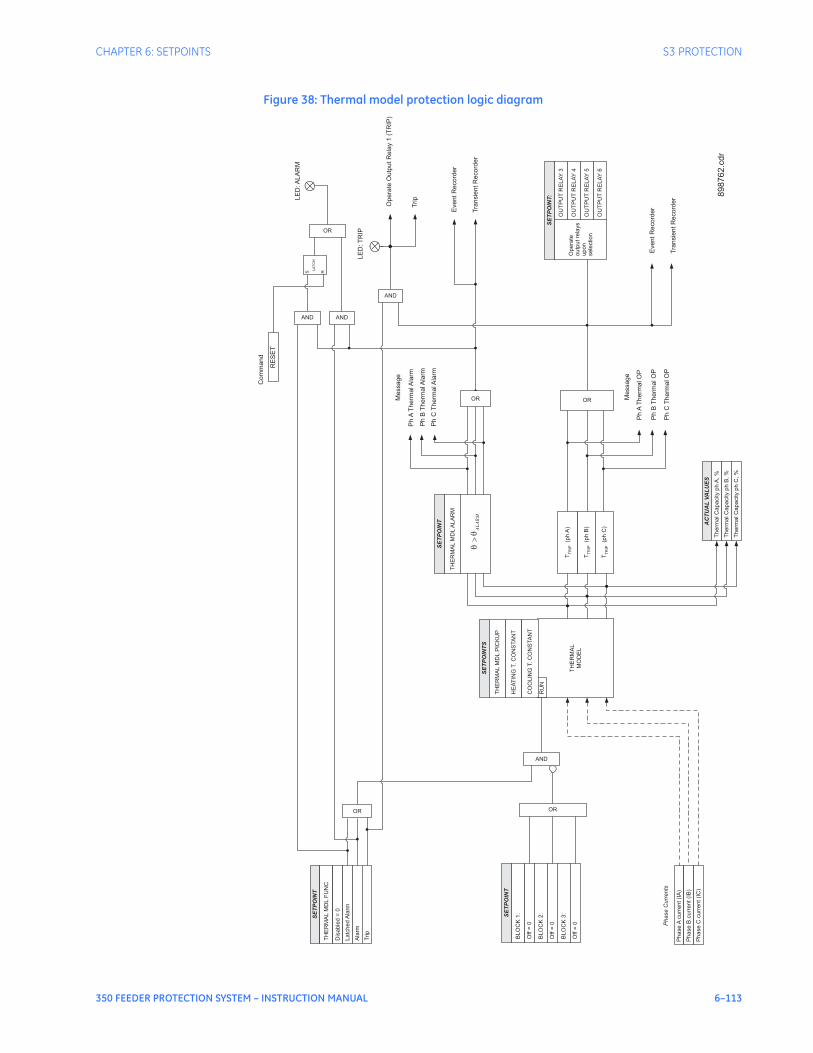
CHAPTER 6: SETPOINTS S3 PROTECTION
350 FEEDER PROTECTION SYSTEM – INSTRUCTION MANUAL 6–113
Figure 38: Thermal model protection logic diagram
SE
TP
OIN
TS
Ph
ase
Acu
rre
nt
(IA
)
RU
N
SE
TP
OIN
T
TH
ER
MA
LM
DL
FU
NC
Dis
ab
led
=0
La
tch
ed
Ala
rm
TH
ER
MA
LM
DL
PIC
KU
P
AND
Ph
ase
Bcu
rre
nt
(IB
)
Ph
ase
Ccu
rre
nt
(IC
)
Op
era
teO
utp
ut
Re
lay
1(T
RIP
)
LE
D:T
RIP
Eve
nt
Re
co
rde
r
Tra
nsie
nt
Re
co
rde
r
Ala
rm
OR
OR
Ph
ase
Cu
rre
nts
AND
SE
TP
OIN
T:
Op
era
te
ou
tpu
tre
lays
up
on
se
lectio
n
OU
TP
UT
RE
LA
Y4
OU
TP
UT
RE
LA
Y5
OU
TP
UT
RE
LA
Y6
OU
TP
UT
RE
LA
Y3
Trip
AND
SE
TP
OIN
T
BL
OC
K1
:
Off
=0
BL
OC
K2
:
Off
=0
BL
OC
K3
:
Off
=0
OR
Me
ssa
ge
TH
ER
MA
L
MO
DE
L
Ph
AT
he
rma
lO
P
Ph
BT
he
rma
lO
P
Ph
CT
he
rma
lO
P
OR
Trip
HE
AT
ING
T.
CO
NS
TA
NT
CO
OL
ING
T.
CO
NS
TA
NT
TT
RIP
(ph
B)
TT
RIP
(ph
C)
TT
RIP
(ph
A)
Th
erm
alC
ap
acity
ph
A,
%
Th
erm
alC
ap
acity
ph
B,
%
Th
erm
alC
ap
acity
ph
C,
%
AC
TU
AL
VA
LU
ES
Ph
AT
he
rma
lA
larm
Me
ssa
ge
OR
SE
TP
OIN
T
TH
ER
MA
LM
DL
AL
AR
M
AL
AR
M�
��
Ph
BT
he
rma
lA
larm
Ph
CT
he
rma
lA
larm
LE
D:A
LA
RM
RE
SE
T
Co
mm
an
d
AND
S R
LA
TC
H
Eve
nt
Re
co
rde
r
Tra
nsie
nt
Re
co
rde
r
898762.c
dr
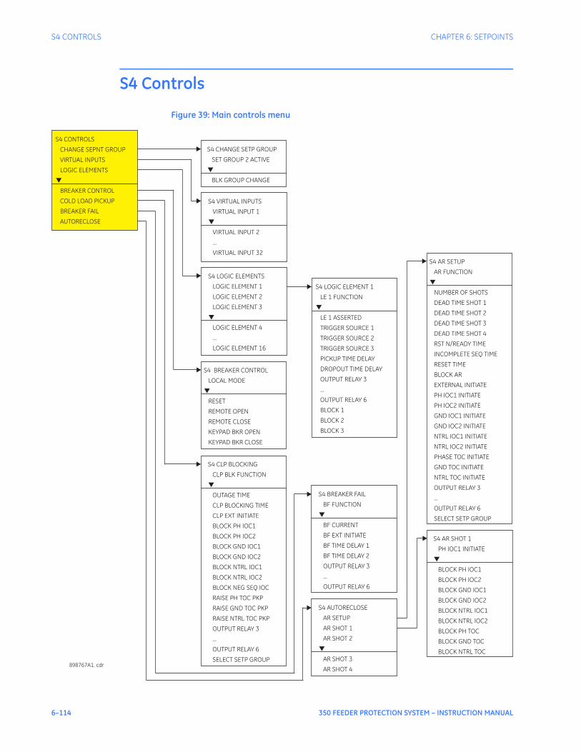
6–114 350 FEEDER PROTECTION SYSTEM – INSTRUCTION MANUAL
S4 CONTROLS CHAPTER 6: SETPOINTS
S4 Controls
Figure 39: Main controls menu
S4 CONTROLS
CHANGE SEPNT GROUP
VIRTUAL INPUTS
LOGIC ELEMENTS
BREAKER CONTROL
COLD LOAD PICKUP
BREAKER FAIL
AUTORECLOSE
▼
S4 CHANGE SETP GROUP
SET GROUP 2 ACTIVE
BLK GROUP CHANGE
▼
S4 BREAKER CONTROL
LOCAL MODE
RESET
REMOTE OPEN
REMOTE CLOSE
KEYPAD BKR OPEN
KEYPAD BKR CLOSE
▼
S4 CLP BLOCKING
CLP BLK FUNCTION
OUTAGE TIME
CLP BLOCKING TIME
CLP EXT INITIATE
BLOCK PH IOC1
BLOCK PH IOC2
BLOCK GND IOC1
BLOCK GND IOC2
BLOCK NTRL IOC1
BLOCK NTRL IOC2
BLOCK NEG SEQ IOC
RAISE PH TOC PKP
RAISE GND TOC PKP
RAISE NTRL TOC PKP
OUTPUT RELAY 3
...
OUTPUT RELAY 6
SELECT SETP GROUP
▼
S4 LOGIC ELEMENT 1
LE 1 FUNCTION
LE 1 ASSERTED
TRIGGER SOURCE 1
PICKUP TIME DELAY
DROPOUT TIME DELAY
OUTPUT RELAY 3
...
OUTPUT RELAY 6
BLOCK 1
BLOCK 2
BLOCK 3
TRIGGER SOURCE 2
TRIGGER SOURCE 3
▼
S4 AR SHOT 1
PH IOC1 INITIATE
BLOCK PH IOC1
BLOCK PH IOC2
BLOCK GND IOC1
BLOCK GND IOC2
BLOCK NTRL IOC1
BLOCK NTRL IOC2
BLOCK PH TOC
BLOCK GND TOC
BLOCK NTRL TOC
▼
S4 AR SETUP
AR FUNCTION
NUMBER OF SHOTS
DEAD TIME SHOT 1
RST N/READY TIME
INCOMPLETE SEQ TIME
RESET TIME
BLOCK AR
EXTERNAL INITIATE
PH IOC1 INITIATE
PH IOC2 INITIATE
GND IOC1 INITIATE
GND IOC2 INITIATE
NTRL IOC1 INITIATE
NTRL IOC2 INITIATE
PHASE TOC INITIATE
GND TOC INITIATE
NTRL TOC INITIATE
OUTPUT RELAY 3
...
OUTPUT RELAY 6
SELECT SETP GROUP
DEAD TIME SHOT 2
DEAD TIME SHOT 3
DEAD TIME SHOT 4
▼
898767A1. cdr
S4 VIRTUAL INPUTS
...
VIRTUAL INPUT 1
VIRTUAL INPUT 2
VIRTUAL INPUT 32
▼
S4 LOGIC ELEMENTS
...
LOGIC ELEMENT 1
LOGIC ELEMENT 2
LOGIC ELEMENT 3
LOGIC ELEMENT 4
LOGIC ELEMENT 16
▼
S4 BREAKER FAIL
BF FUNCTION
BF CURRENT
BF EXT INITIATE
BF TIME DELAY 1
...
OUTPUT RELAY 6
BF TIME DELAY 2
OUTPUT RELAY 3
▼
S4 AUTORECLOSE
AR SETUP
AR SHOT 1
AR SHOT 2
AR SHOT 3
AR SHOT 4
▼

CHAPTER 6: SETPOINTS S4 CONTROLS
350 FEEDER PROTECTION SYSTEM – INSTRUCTION MANUAL 6–115
Change setpoint groupThe 350 relay has two identical setpoint groups- Group 1 and Group 2 for all protection elements. Switching between these two groups is available automatically by assigning an input (contact, virtual, remote, logic element), or via communications.Group 1 is the default setpoint group. The relay can automatically switch from Group 1 protections to Group 2 protections, and vice versa, by setting up the switching conditions under “Change Setpoint Group”. Under some application conditions, such as an overcurrent element pick up, it may not be desirable to change setpoint groups. A setpoint change can also be prevented if the breaker is open, so that a fault detected before a reclosure will not cause a group change while the breaker is open. In such cases, the user can set a condition under “BLK GROUP CHANGE”, where if asserted, the active setpoint group will stay active, even if the input configured to switch to the other setpoint group is asserted. For example if the active group was Group 1 at the time of a trip, the breaker opens, and the input configured under “BLK GROUP CHANGE” is asserted, the relay will maintain Setpoint Group 1, even if the input “SET GROUP 2 ACTIVE” is asserted. Vice versa, if the “BLK GROUP CHANGE” input is asserted; the relay will not switch from Group 2 to Group 1, even if the input under “SET GROUP 2 ACTIVE” is de-asserted.The relay will default to Setpoint Group 1, if both the input “SET GROUP 2 ACTIVE” and the blocking input “BLK GROUP CHANGE” are de-asserted. Switching from Group 1 to Group 2 can be also initiated by the Autoreclose, or the Cold Load Pickup functions. If the setpoint group selected in the Autoreclosure menu is different from the active setpoint group, then the Autoreclosure function will force the relay to apply the Autoreclosure selected setpoint group. The Autoreclosure function will then apply the AR shot settings to the corresponding protections. The relay will revert to the previous setpoint group after detecting the Autoreclosure resets. Similarly, if “Enabled” and not blocked by the Autoreclosure, the Cold Load Pickup function will force the relay to apply the protections of the other setpoint group, if the one selected under the CLP menu is different from this, being in-service. The relay will revert to the setpoint group used originally, after the CLP blocking function resets.PATH: CONTROLS > CHANGE SPNT GROUP
SET GROUP 2 ACTIVE
Range: Off, Contact Input 1 to 10[8], Virtual Input 1 to 32, Remote Input 1 to 32, Logic Elements 1 to 16Default: Off
This setting selects an input used to change from Setpoint Group 1 to Setpoint Group 2, when asserted. If no group change supervision is selected, Setpoint group 2 will stay active as long as the “SET GROUP 2 ACTIVE” input is asserted, and will revert to Group 1, when this input is de-asserted.
BLOCK GROUP CHANGE
Range: Off, Contact Input 1 to 10[8], Virtual Input 1 to 32, Remote Input 1 to 32, Logic Elements 1 to 16Default: Off
This setting defines an input that can be used to block changing setpoint groups. When the assigned input is asserted, changing from one setpoint group to the other one is blocked.
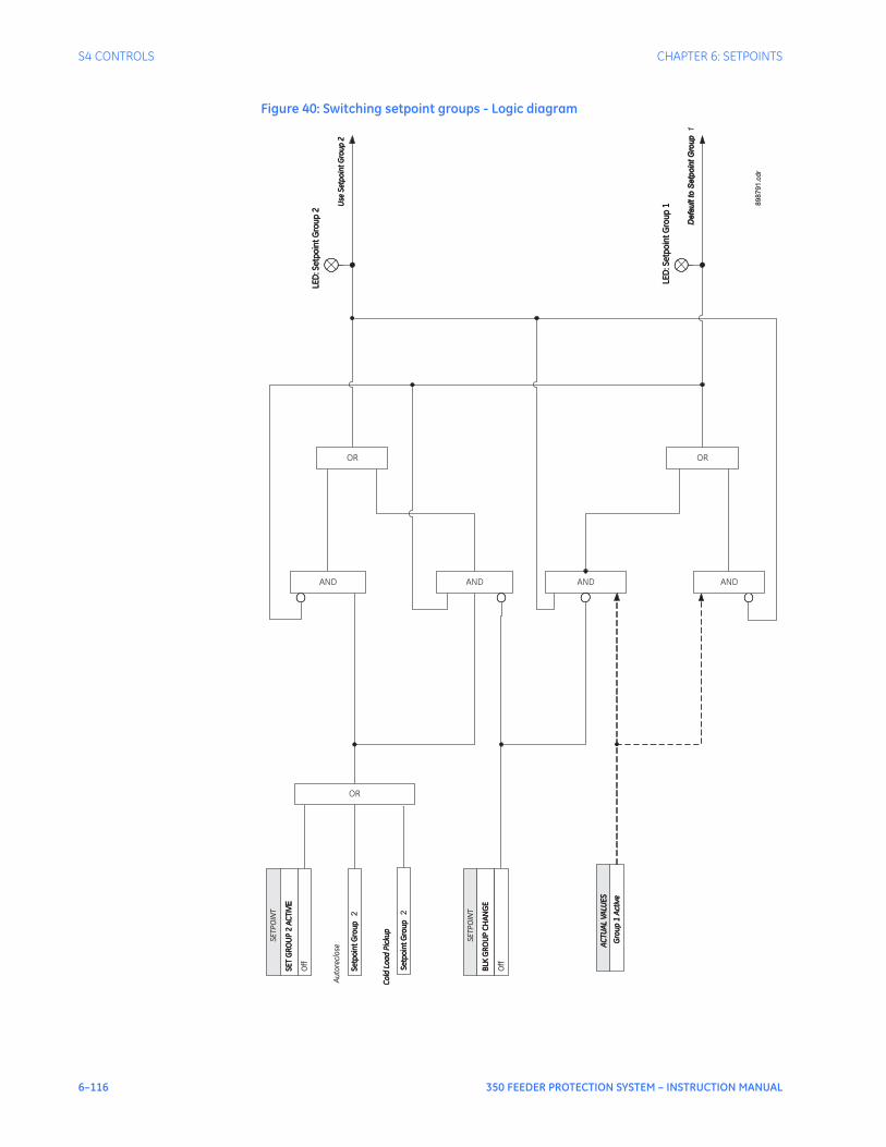
6–116 350 FEEDER PROTECTION SYSTEM – INSTRUCTION MANUAL
S4 CONTROLS CHAPTER 6: SETPOINTS
Figure 40: Switching setpoint groups - Logic diagram
SE
TP
OIN
T
SE
TG
RO
UP
2A
CT
IVE
SE
TG
RO
UP
2A
CT
IVE
Off
SE
TP
OIN
T
BLK
GR
OU
PC
HA
NG
EB
LKG
RO
UP
CH
AN
GE
Off
Use
Se
tpo
int
Gro
up
2U
se
Se
tpo
int
Gro
up
2
Se
tpo
int
Gro
up
Se
tpo
int
Gro
up
2
Au
tore
clo
se
Se
tpo
int
Gro
up
Se
tpo
int
Gr o
up
2
Co
ldLo
ad
Pic
ku
pC
old
Lo
ad
Pic
ku
p
De
fau
ltto
Se
tpo
int
Gro
up
De
fau
ltto
Se
tpo
int
Gro
up
1
Gro
up
1A
cti
ve
Gro
up
1A
cti
ve
AC
TU
AL
VA
LU
ES
AC
TU
AL
VA
LU
ES
LED
: Se
tpo
int
Gro
up
2LE
D:S
etp
oin
tG
rou
p2
LED
: Se
tpo
int
Gro
up
1LE
D: S
etp
oin
tG
rou
p1 8
98791.c
dr
OR OR
OR
AND AND AND AND

CHAPTER 6: SETPOINTS S4 CONTROLS
350 FEEDER PROTECTION SYSTEM – INSTRUCTION MANUAL 6–117
Virtual inputsThere are 32 virtual inputs that can be individually programmed to respond to input commands entered via the relay keypad, or by using communication protocols.PATH: SETPOINTS > S4 CONTROLS > VIRTUAL INPUTS.
VIRTUAL INPUT 1
Range: Off, OnDefault: Off
The state of each virtual input can be controlled under SETPOINTS > S4 CONTROL > VIRTUAL INPUTS menu. For this purpose, each of the virtual inputs selected for control need be “Enabled” under SETPOINTS > S5 INPUTS/OUTPUTS > VIRTUAL INPUTS, and its type “Self-Reset” or “Latched” specified.If Self-Reset type was selected, entering “On” command will lead to a pulse of one protection pass. To prolong the time of the virtual input pulse, one can assign it as a trigger source to a Logic Element with a dropout timer set to the desired pulse time. If “Latched” type is selected, the state of the virtual input will be latched, upon entering “On” command.Refer to the logic diagram in the S5 INPUTS/OUTPUTS > VIRTUAL INPUTS chapter for more details.
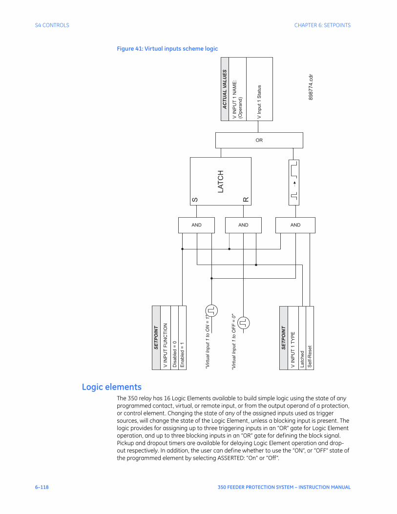
6–118 350 FEEDER PROTECTION SYSTEM – INSTRUCTION MANUAL
S4 CONTROLS CHAPTER 6: SETPOINTS
Figure 41: Virtual inputs scheme logic
Logic elementsThe 350 relay has 16 Logic Elements available to build simple logic using the state of any programmed contact, virtual, or remote input, or from the output operand of a protection, or control element. Changing the state of any of the assigned inputs used as trigger sources, will change the state of the Logic Element, unless a blocking input is present. The logic provides for assigning up to three triggering inputs in an “OR” gate for Logic Element operation, and up to three blocking inputs in an “OR” gate for defining the block signal. Pickup and dropout timers are available for delaying Logic Element operation and drop-out respectively. In addition, the user can define whether to use the “ON”, or “OFF” state of the programmed element by selecting ASSERTED: “On” or “Off”.
SE
TP
OIN
T
VIN
PU
TF
UN
CT
ION
Dis
able
d=
0
Enable
d=
1
AND
SE
TP
OIN
T
VIN
PU
T1
TY
PE
Latc
hed
Self-R
eset
AND AND
“Virtu
alIn
put1
toO
N=
1"
“Virtu
alIn
put1
toO
FF
=0"
S R
LA
TC
H
OR
AC
TU
AL
VA
LU
ES
VIN
PU
T1
NA
ME
:
(Opera
nd)
VIn
put1
Sta
tus
89
87
74
.cd
r

CHAPTER 6: SETPOINTS S4 CONTROLS
350 FEEDER PROTECTION SYSTEM – INSTRUCTION MANUAL 6–119
Referring to the Logic Element logic diagram below, the Logic Element can be set to one of four functions: Control, Alarm, Latched Alarm, or Trip. When Alarm or Latched Alarm is selected, the output relay #1 (Trip) is not triggered during Logic Element operation. The Trip output relay will be triggered when Trip is selected as the function, and the Logic Element operates. The Logic Element function can be also selected as Control, and used with other relay elements without turning on the “ALARM” and “TRIP” LEDs. The “PICKUP” LED will turn on upon a Logic Element pickup condition except when the Logic Element function is selected as Control. The “ALARM” LED will turn on upon Logic Element operation if the Logic Element function selected is either Alarm, or Latched Alarm. The “TRIP” LED will turn on upon Logic Element operation if the Logic Element function is selected as Trip. The option to trigger auxiliary output relays is provided for any of the selected Logic Element functions.The following path is available using the keypad. For instructions on how to use the keypad, please refer to Chapter 3 - Working with the Keypad.PATH: SETPOINTS > S4 CONTROLS > S4 LOGIC ELEMENTS
LE1(16) FUNCTION
Range: Disabled, Control, Alarm, Latched Alarm, TripDefault: Disabled
This setting defines the use of the Logic Element. When Trip is selected as a function, the Logic Element will trigger Output Relay # 1 (Trip) upon operation.
LE1(16) ASSERTED
Range: On, OffDefault: Off
This setting defines the Logic Element state “On” or “Off” to be used as an output. The asserted “On” selection provides an output “high” when the LE is "On". If asserted “Off” is selected, then the LE output will be “high”, when the LE is “Off”.
TRIGGER SOURCE 1, 2, 3
Range: Off, Any input from the list of inputsDefault: Off
Each of the three trigger sources is configurable by allowing the assigning of an input selected from a list of inputs. This input can be a contact input, a virtual input, a remote input, or an output flag from a protection, or control element. See the list of available inputs from the table below.
TRIGGER LOGIC
Range: OR, ANDDefault: OR
This setting defines trigger source operation as either “OR” or “AND”. When set to “OR” any of the inputs will trigger the Logic Element. When set to “AND” all three sources must be asserted before the Logic Element is triggered.
PKP TIME DELAY
Range: 0 to 60000 ms in steps of 1 msDefault: 0 ms
This setting specifies the pickup time delay before Logic Element operation.
DPO TIME DELAY
Range: 0 to 60000 ms in steps of 1 msDefault: 0 ms
This setting specifies the time delay from a reset timer that starts upon expiry of the pickup time delay and prolongs the operation of the Logic Element until this time expires.

6–120 350 FEEDER PROTECTION SYSTEM – INSTRUCTION MANUAL
S4 CONTROLS CHAPTER 6: SETPOINTS
OUTPUT RELAYS 3 to 6
Range: Do not operate, OperateDefault: Do not operate
Any or all of output relays 3 to 6 can be selected to operate upon a Logic Element operating condition. The selection of auxiliary relay outputs is available no matter whether the Control, Alarm, Latched Alarm, or Trip function is selected.
BLOCK 1, 2, 3
Range: Off, Any input from the list of inputsDefault: Off
Each of the three blocks is configurable by allowing the assigning of an input selected from a list of inputs. This input can be a contact input, a virtual input, a remote input, or an output flag from a protection, or control element, as well as an input from any of the other seven logic inputs. See the list of available inputs from the table below
BLOCK LOGIC
Range: OR, ANDDefault: OR
This setting defines block source operation as either “OR” or “AND”. When set to “OR” any of the inputs will block the Logic Element. When set to “AND” all three sources must be asserted before the Logic Element is blocked.
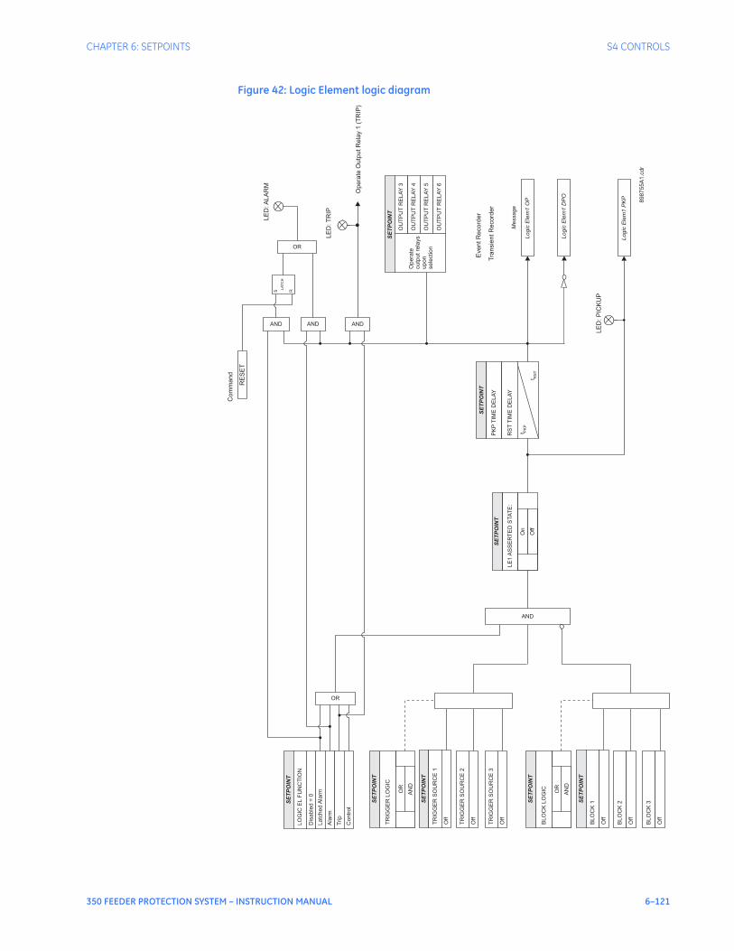
CHAPTER 6: SETPOINTS S4 CONTROLS
350 FEEDER PROTECTION SYSTEM – INSTRUCTION MANUAL 6–121
Figure 42: Logic Element logic diagram
SE
TP
OIN
T
TR
IGG
ER
SO
UR
CE
1
Off
TR
IGG
ER
SO
UR
CE
2
Off
TR
IGG
ER
SO
UR
CE
3
Off
SE
TP
OIN
T
BL
OC
K1
Off
BL
OC
K2
Off
BL
OC
K3
Off
AND
PK
PT
IME
DE
LA
Y
SE
TP
OIN
T
t PK
P
t RS
T
LE
1A
SS
ER
TE
DS
TA
TE
:
SE
TP
OIN
T
t PK
P
Off
On
EventR
ecord
er
Tra
nsie
ntR
ecord
er
SE
TP
OIN
T
OU
TP
UT
RE
LA
Y4
OU
TP
UT
RE
LA
Y5
OU
TP
UT
RE
LA
Y6
OU
TP
UT
RE
LA
Y3
RS
TT
IME
DE
LA
Y
Lo
gic
Ele
m1
OP
Lo
gic
Ele
m1
PK
P
LE
D:P
ICK
UP
Me
ssa
ge
SE
TP
OIN
T
LO
GIC
EL
FU
NC
TIO
N
Dis
ab
led
=0
La
tch
ed
Ala
rm
Opera
teO
utp
utR
ela
y1
(TR
IP)
LE
D:A
LA
RM
LE
D:T
RIP
Ala
rm
OR
OR
AND
RE
SE
T
Com
mand
Trip
ANDAND
Co
ntr
ol
S R
LA
TC
H
898755A
1.c
dr
Lo
gic
Ele
m1
DP
O
t PK
P
TR
IGG
ER
LO
GIC
SE
TP
OIN
T
AN
D
OR t P
KP
BL
OC
KL
OG
IC
SE
TP
OIN
T
AN
D
OR
Opera
te
outp
ut
rela
ys
upon
sele
ction
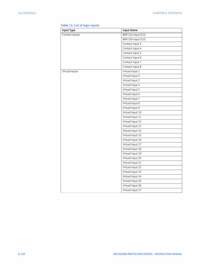
6–122 350 FEEDER PROTECTION SYSTEM – INSTRUCTION MANUAL
S4 CONTROLS CHAPTER 6: SETPOINTS
Table 11: List of logic inputsInput Type Input Name
Contact Inputs BKR 52a input (CI1)
BKR 52b input (CI2)
Contact Input 3
Contact Input 4
Contact Input 5
Contact Input 6
Contact Input 7
Contact Input 8
Virtual Inputs Virtual Input 1
Virtual Input 2
Virtual Input 3
Virtual Input 4
Virtual Input 5
Virtual Input 6
Virtual Input 7
Virtual Input 8
Virtual Input 9
Virtual Input 10
Virtual Input 11
Virtual Input 12
Virtual Input 13
Virtual Input 14
Virtual Input 15
Virtual Input 16
Virtual Input 17
Virtual Input 18
Virtual Input 19
Virtual Input 20
Virtual Input 21
Virtual Input 22
Virtual Input 23
Virtual Input 24
Virtual Input 25
Virtual Input 26
Virtual Input 27
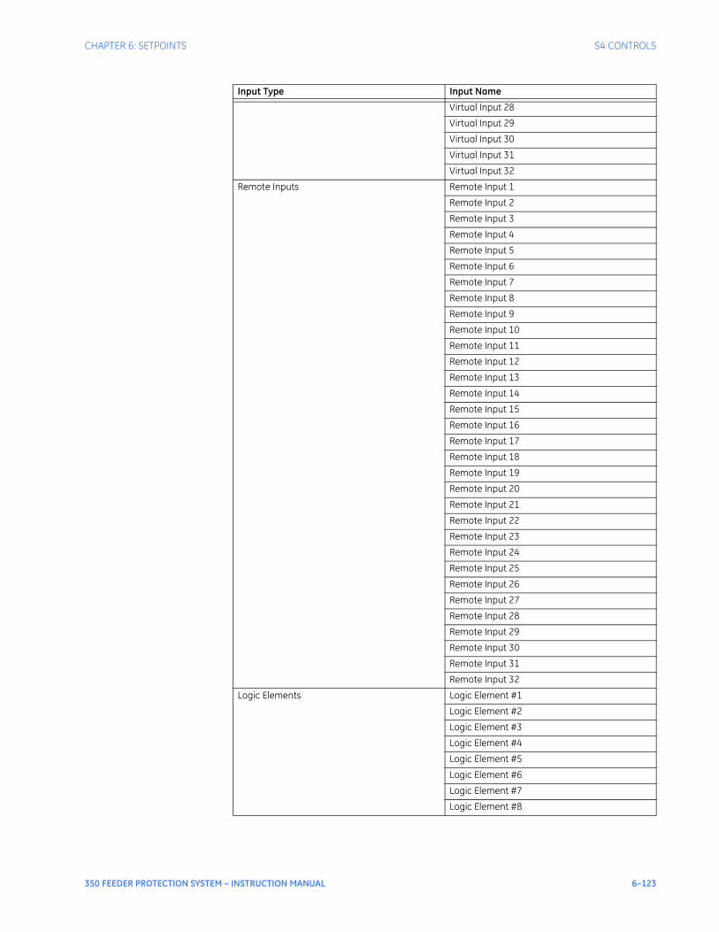
CHAPTER 6: SETPOINTS S4 CONTROLS
350 FEEDER PROTECTION SYSTEM – INSTRUCTION MANUAL 6–123
Virtual Input 28
Virtual Input 29
Virtual Input 30
Virtual Input 31
Virtual Input 32
Remote Inputs Remote Input 1
Remote Input 2
Remote Input 3
Remote Input 4
Remote Input 5
Remote Input 6
Remote Input 7
Remote Input 8
Remote Input 9
Remote Input 10
Remote Input 11
Remote Input 12
Remote Input 13
Remote Input 14
Remote Input 15
Remote Input 16
Remote Input 17
Remote Input 18
Remote Input 19
Remote Input 20
Remote Input 21
Remote Input 22
Remote Input 23
Remote Input 24
Remote Input 25
Remote Input 26
Remote Input 27
Remote Input 28
Remote Input 29
Remote Input 30
Remote Input 31
Remote Input 32
Logic Elements Logic Element #1
Logic Element #2
Logic Element #3
Logic Element #4
Logic Element #5
Logic Element #6
Logic Element #7
Logic Element #8
Input Type Input Name
6–124 350 FEEDER PROTECTION SYSTEM – INSTRUCTION MANUAL
S4 CONTROLS CHAPTER 6: SETPOINTS
Breaker controlThe Breaker Control menu is designed to trip and close the breaker from the relay either remotely (LOCAL MODE setting set to "OFF," or the selected contact input deselected) or locally (the input from the LOCAL MODE setpoint asserted). While in LOCAL MODE, the REMOTE OPEN and CLOSE setpoints are not active.The following path is available using the keypad. For instructions on how to use the keypad, please refer to Chapter 3 - Working with the Keypad.PATH: SETPOINTS > S4 CONTROLS > BREAKER CONTROL
LOCAL MODE
Range: Off, Contact Input 1 to 10[8], Virtual Input 1 to 32, Remote Input 1 to 32, Logic Elements1 to 16Default: Off
The LOCAL MODE setting places the relay in local mode. The relay is in Remote Mode, if not forced into Local Mode by this setpoint (i.e. LOCAL MODE set to "OFF," or the selected input de-asserted).
RESET
Range: Off, Contact Input 1 to 10[8], Virtual Input 1 to 32, Remote Input 1 to 32, Logic Elements1 to 16Default: Off
The RESET setting resets the latched alarm or Trip LEDs, and the latched relays.
REMOTE OPEN
Range: Off, Contact Input 1 to 10[8], Virtual Input 1 to 32, Remote Input 1 to 32, Logic Elements1 to 16Default: Off
This setting specifies the input which when asserted, initiates a trip (output relay #1 TRIP energized) and opens the breaker.
REMOTE CLOSE
Range: Off, Contact Input 1 to 10[8], Virtual Input 1 to 32, Remote Input 1 to 32, Logic Elements 1 to 16Default: Off
This setting specifies the input which when asserted initiates a close (output relay #2 CLOSE energized) and closes the breaker.
KEYPAD BKR OPEN
Range: Yes, NoDefault: No
This setting provides flexibility to the user to open the breaker from the keypad. Selecting “Yes” will introduce a pulse of 100ms to the "trip" output relay. The setting is active, when the selected input under LOCAL MODE setpoint is asserted
KEYPAD BKR CLOSE
Range: Yes, NoDefault: No
This setting provides flexibility to the user to close the breaker from the keypad. Selecting “Yes” will introduce a pulse of 100ms to the "close" output relay. The setting is active, when the selected input under LOCAL MODE setpoint is asserted
By default, the breaker control mode is set to "Remote" ( LOCAL MODE set to "OFF"). In this mode, only the REMOTE OPEN and REMOTE CLOSE setpoints are active. The rest of the setpoints with exception of the RESET setpoint are deactivated, regardless of the status of their selected inputs.
CHAPTER 6: SETPOINTS S4 CONTROLS
350 FEEDER PROTECTION SYSTEM – INSTRUCTION MANUAL 6–125
Local Mode is set if the input for the LOCAL MODE setpoint is asserted. In this mode, the REMOTE OPEN and REMOTE CLOSE setpoints are deactivated, regardless of the status of their selected inputs. Breaker Open and Breaker Close commands from the KEYPAD BKR OPEN and KEYPAD BKR CLOSE setpoints will be active, if the breaker operation is set to Local Mode (i.e. the selected input under the LOCAL MODE setpoint asserted).
Cold load pickupThe 350 can be programmed to block the instantaneous over-current elements, and raise the pickup level of the time over-current elements, when a cold load condition is detected. The cold load condition is detected during closing of the breaker on a feeder that has been de-energized for a long time. The feeder inrush current and the motor accelerating current during breaker closing may be above some over-current protection settings. The diagram shows the slow decaying of the cold load current starting at about 500% of the nominal current at the time of breaker closing, decaying down to 300% after 1 second, 200% after 2 seconds, and 150% after 3 seconds.
Figure 43: Cold load pickup
The relay detects Cold Load condition (Cold Load Pickup armed), if the currents on all three phases drop below 3% of the CT nominal rating for the period of time greater, than the Outage Time Before Cold Load setting. The Cold Load condition can be immediately initiated (Outage Time Before Cold Load timer bypassed), by asserting a contact input selected for External CLP Initiate. The second timer Cold Load Pickup Block is used to specify the time of blocking the instantaneous over-current elements, and the time of raised pickup levels of the time over-current elements, after breaker closing. The timer starts when at least one of the three phase currents is above 10% of CT nominal. Upon timer expiration, the settings return to normal.The following path is available using the keypad. For instructions on how to use the keypad, please refer to Chapter 3 - Working with the Keypad.PATH: SETPOINTS > S4 CONTROLS > COLD LOAD PICKUP
Time (seconds)
Curr
ent(%
ofnom
inal)
0
100
200
300
400
500
-1 0 1 2 3 4 5 6
OUTAGE
PICKUP PICKUP
LOAD ENERGIZED
X
NORMAL TRIP SETTING
898750.CDR
6–126 350 FEEDER PROTECTION SYSTEM – INSTRUCTION MANUAL
S4 CONTROLS CHAPTER 6: SETPOINTS
CLP BLK FUNCTION
Range: Disabled, Alarm, Latched AlarmDefault: Disabled
If set to Alarm, the alarm LED will flash upon detection of Cold Load Pickup condition, and will turn off upon clearing the condition. If Latched Alarm setting is selected, the alarm LED will flash during the Cold Load Pickup condition, and will remain ON, when the condition is cleared. The Alarm LED turns OFF upon manual or remote reset command.
OUTAGE TIME
Range: 1 to 1000 min in steps of 1 minDefault: 20 min
This timer starts when the feeder is de-energized (currents drop below 3% of CT nominal). The Cold Load Pickup is armed after its time expiration.
CLP BLOCKING TIME
Range: 1 to 1000 sec in steps of 1 secDefault: 5 s
This setting sets the time of blocking for the selected instantaneous overcurrent elements, and the time of raised pickup level of the time overcurrent elements. This timer starts when currents bigger than 10% of CT nominal are detected.
CLP EXT INITIATE
Range: Off, Contact Input 1 to 10[8], Virtual Input 1 to 32, Remote Input 1 to 32, Logic Input 1 to 16Default: Off
This setting allows the user to select Contact Input, Virtual Input, Remote Input, or Logic Element, and force the CLP element into the Cold Load Pickup armed state, bypassing the timer Outage Time Before Pickup.
BLOCK PH IOC1(2)/ BLOCK GND [S.GND] IOC1(2)/ BLOCK NTRL IOC1(2) / BLOCK NEG SEQ IOC
Range: No, YesDefault: No
Each instantaneous over-current element from the list can be selected for block or not, upon cold load pickup condition.
RAISE PH TOC PKP/ RAISE GND [S.GND] TOC PKP/ RAISE NTRL TOC PKP
Range: 0 to 100% in steps of 1%Default: 0%
The pickup level of each time over-current element from the list can be raised by 0 to 100%, upon cold load pickup condition.
OUTPUT RELAYS 3 to 6
Range: Do not operate, OperateDefault: Do not operate
Each of the output relays can be programmed to operate when cold load pickup function is armed.
SELECT SETP GROUP
Range: Active Group, SP Group 1 Active, SP Group 2 ActiveDefault: Active Group
The CLP blocking function will block the IOC, and adjust the TOC pickup levels for the over-current elements from whichever Setting Group is active, if the setting Active Group is selected.
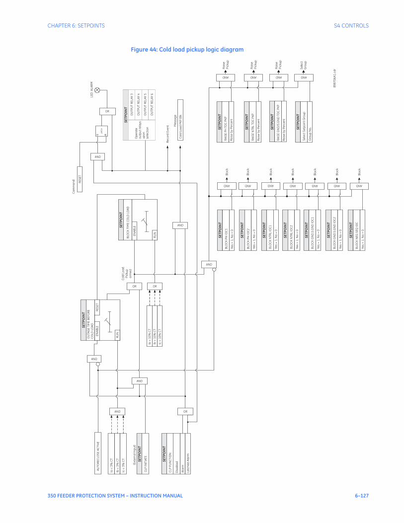
CHAPTER 6: SETPOINTS S4 CONTROLS
350 FEEDER PROTECTION SYSTEM – INSTRUCTION MANUAL 6–127
Figure 44: Cold load pickup logic diagram
Ia<
3%
CT
Ib<
3%
CT
Ic<
3%
CT
Ia<
10
%C
T
Ib<
10
%C
T
Ic<
10
%C
T
CLP
INIT
IAT
E
CLP
FU
NC
TIO
N:
Dis
ab
led
Ala
rm
Latc
he
dA
larm
OU
TAG
ET
IME
BE
FO
RE
CO
LDLO
AD
EN
AB
LER
ES
ET
RU
N
BLO
CK
TIM
EC
OLD
LOA
D
EN
AB
LE
RU
N
BLO
CK
PH
IOC
1
BLO
CK
PH
IOC
2
BLO
CK
NT
RL
IOC
1
BLO
CK
NT
RL
IOC
2
BLO
CK
GN
D.S
.GN
DIO
C1
BLO
CK
GN
D.S
.GN
DIO
C2
Ye
s=
1, N
o=
0
Ye
s=
1, N
o=
0
Ye
s=
1, N
o=
0
Ye
s=
1, N
o=
0
Ye
s=
1, N
o=
0
Ye
s=
1,N
o=
0
RE
SE
T
LED
: AL
AR
M
OU
TP
UT
RE
LA
Y3
OU
TP
UT
RE
LA
Y4
OU
TP
UT
RE
LA
Y5
OU
TP
UT
RE
LA
Y6
Op
era
teo
utp
ut
rela
ys
up
on
sele
cti
on
Re
co
rdE
ve
nt M
ess
ag
e
Co
ldLo
ad
PK
PB
lk
RA
ISE
PH
TOC
PK
P
RA
ISE
NT
RL
TOC
PK
P
RA
ISE
GN
D/S
.GN
DTO
CP
KP
Ra
ise
by
Pe
rce
nt
Ra
ise
by
Pe
rce
nt
Ra
ise
by
Pe
rce
nt
Blo
ck
Blo
ck
Blo
ck
Blo
ck
Blo
ck
Blo
ck
Se
lec
tS
etp
oin
tG
rou
p
Gro
up
No
.
Ra
ise
Pic
kup
Ra
ise
Pic
kup
Ra
ise
Pic
kup
Se
lec
tG
rou
p
89
87
06
A1
. cd
rAND AND AND AND AND AND
AND AND AND AND
AND
AND
OR
AND
OR OR
AND
AND
AND
OR
Co
mm
an
d
LA
TCH
Co
ldLo
ad
Pic
kup
arm
ed
(Ex
tern
al I
np
ut)
AU
TOR
EC
LOS
EA
CT
IVE
SE
TP
OIN
T
SE
TP
OIN
T
SE
TP
OIN
T
SE
TP
OIN
T
SE
TP
OIN
T
SE
TP
OIN
T
SE
TP
OIN
T
SE
TP
OIN
T
SE
TP
OIN
T
SE
TP
OIN
T
SE
TP
OIN
T
SE
TP
OIN
T
SE
TP
OIN
T
SE
TP
OIN
T
SE
TP
OIN
T
BLO
CK
NE
GS
EQ
IOC
Ye
s=
1,N
o=
0B
loc
k
AND
SE
TP
OIN
T

6–128 350 FEEDER PROTECTION SYSTEM – INSTRUCTION MANUAL
S4 CONTROLS CHAPTER 6: SETPOINTS
Breaker failureThe Breaker Failure function monitors the phase currents, after a trip command from the protection elements is initiated. If any phase current is above the set current level after the BF DELAY time expires, a breaker failure will be declared, and will operate the selected output relays. The Breaker failure scheme provides also an external input to initiate breaker failure via Contact Input, Virtual Input, Remote Input, or Logic Element. The following path is available using the keypad. For instructions on how to use the keypad, please refer to Chapter 3 - Working with the Keypad.PATH: SETPOINTS > S4 CONTROLS > BREAKER FAIL
BF FUNCTION
Range: Disabled, Alarm, Latched AlarmDefault: Disabled
If set to Alarm, the alarm LED will flash upon detection of Breaker Failure condition, and will turn off upon clearing the condition. If Latched Alarm setting is selected, the alarm LED will flash during the Breaker Failure condition, and will remain ON, when the condition is cleared. The Alarm LED turns OFF upon manual or remote reset command.
BF CURRENT
Range: 0.05 to 20.00 x CT in steps of 0.01Default: 1.00 x CT
This setting selects the current level to be monitored by the BF logic, after the programmed time delays.
BF EXT INITIATE
Range: Off, Contact Input 1 to 10[8], Virtual Input 1 to 32, Remote Input 1 to 32, Logic Element 1 to 16Default: Off
This setting allows the user to select Contact Input, Virtual or Remote Input, Logic Element to initiate the Breaker Failure logic.
BF TIME DELAY 1
Range: 0.03 to 1.00 s in steps of 0.01 sDefault: 0.10 s
This timer starts when breaker trip command is issued from any of the protection elements.
BF TIME DELAY 2
Range: 0.00 to 1.00 s in steps of 0.01 sDefault: 0.00 s
This timer does not start until a trip condition is recognized, BF TIMER DELAY 1 has expired, and at least one of the phase currents is above the BF CURRENT setting.
OUTPUT RELAY 3 to 6
Range: Do not operate, OperateDefault: Do not operate
Each of the output relays can be programmed to operate upon detection of breaker failure.
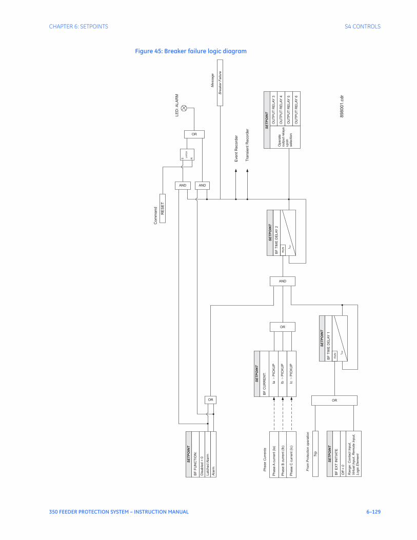
CHAPTER 6: SETPOINTS S4 CONTROLS
350 FEEDER PROTECTION SYSTEM – INSTRUCTION MANUAL 6–129
Figure 45: Breaker failure logic diagram
SE
TP
OIN
T
Ph
ase
Acu
rre
nt
(Ia
)
SE
TP
OIN
T
BF
FU
NC
TIO
N:
Dis
ab
led
=0
La
tch
ed
Ala
rm
BF
CU
RR
EN
T:
Ph
ase
Bcu
rre
nt
(Ib
)
Ph
ase
Ccu
rre
nt
(Ic)
Eve
nt
Re
co
rde
r
Tra
nsie
nt
Re
co
rde
r
Ala
rm
OR
OR
Trip
Ph
ase
Cu
rre
nts
AND
SE
TP
OIN
T
Op
era
te
ou
tpu
tre
lays
up
on
se
lectio
n
OU
TP
UT
RE
LA
Y4
OU
TP
UT
RE
LA
Y5
OU
TP
UT
RE
LA
Y6
OU
TP
UT
RE
LA
Y3
Ib>
PIC
KU
P
Ia>
PIC
KU
P
Ic>
PIC
KU
P
OR
AND
SE
TP
OIN
T
BF
EX
TIN
ITIA
TE
Off
=0
Ra
ng
e:
Co
nta
ct
Inp
ut,
Virtu
alIn
pu
t,R
em
ote
Inp
ut,
Lo
gic
Ele
me
nt
Fro
mP
rote
ctio
no
pe
ratio
n
OR
BF
TIM
ED
EL
AY
1
SE
TP
OIN
T
t PK
P
RU
N
BF
TIM
ED
EL
AY
2
SE
TP
OIN
T
t PK
P
RU
N
Bre
ake
rF
ailu
re
Me
ssa
ge
LE
D:A
LA
RM
RE
SE
T
Co
mm
an
d
AND
S R
LA
TC
H
89
80
01
.cd
r

6–130 350 FEEDER PROTECTION SYSTEM – INSTRUCTION MANUAL
S4 CONTROLS CHAPTER 6: SETPOINTS
AutorecloserThe automatic recloser is intended for use on single three-pole tripping breaker applications. Up to four reclosing “shots” can be programmed with independent set of protection elements for initiation, and individual dead time prior to each subsequent shot. A typical example for selection of individual set of overcurrent protection elements for initiation is the selection of instantaneous overcurrent protections for the first AR initiation, and selection of time overcurrent protections after the first reclose. This would provide longer time before the breaker opens, and allow the fuses to burn off, if the fault is still present.
NOTE
NOTE: To synchronize the Reclose function with the breaker status feedback, it is recommended that a debounce of 2 cycles is used, regardless of whether the breaker status is detected using one or both contacts.
The following path is available using the keypad. For instructions on how to use the keypad, please refer to Chapter 3 - Working with the Keypad.PATH: SETPOINTS > S4 CONTROLS > AUTORECLOSE > AR SETUP
AR FUNCTION
Range: Disabled, EnabledDefault: Disabled
This setting enables or disables the Autorecloser function.
NUMBER OF SHOTS
Range: 1 to 4, step 1Default: 1
The maximum number of reclosures that will be attempted before AR Not Ready.
DEAD TIME SHOT 1 to 4
Range: 0.1 to 600.0 s, step 0.1 sDefault: 1.0 s
This setting specifies the dead time delay before each reclosure. Four time delay settings are to be configured and used to time out before the first, second, third, or fourth breaker reclosure.
RST N/READY TIME
Range: 0.1 to 600.0 s, step 0.1 sDefault: 10 s
This setting specifies the reset AR Not Ready time. Upon breaker close, the timer times out, and resets the AR lockout.
INCOMP SEQ TIME
Range: 0.1 to 600.0 s, step 0.1 sDefault: 5.0 s
This timer is used to set the maximum time interval allowed for single reclosure shot. The timer starts timing out for both situations: upon AR initiate to open the breaker, where the breaker doesn’t open, or whenever breaker reclose command is issued, where the breaker doesn’t close. Upon incomplete sequence time expiry, the AR goes into AR Not Ready mode.
RESET TIME
Range: 0.1 to 600.0 s, step 0.1 sDefault: 5.0 s
This time is used to reset the AR into AR ready mode after successful reclosure. If no breaker tripping occurs within the reset time, the AR shot counter is reset.
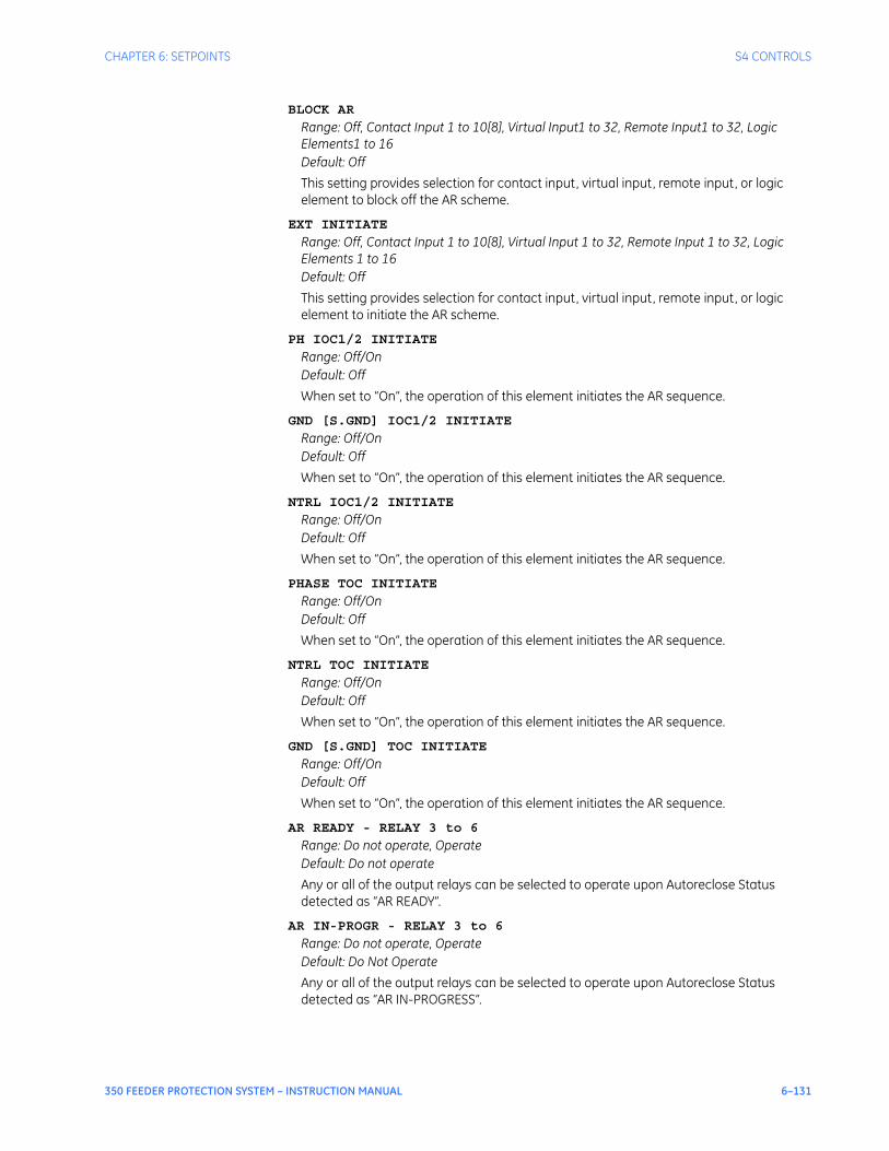
CHAPTER 6: SETPOINTS S4 CONTROLS
350 FEEDER PROTECTION SYSTEM – INSTRUCTION MANUAL 6–131
BLOCK AR
Range: Off, Contact Input 1 to 10[8], Virtual Input1 to 32, Remote Input1 to 32, Logic Elements1 to 16Default: Off
This setting provides selection for contact input, virtual input, remote input, or logic element to block off the AR scheme.
EXT INITIATE
Range: Off, Contact Input 1 to 10[8], Virtual Input 1 to 32, Remote Input 1 to 32, Logic Elements 1 to 16Default: Off
This setting provides selection for contact input, virtual input, remote input, or logic element to initiate the AR scheme.
PH IOC1/2 INITIATE
Range: Off/OnDefault: Off
When set to “On”, the operation of this element initiates the AR sequence.
GND [S.GND] IOC1/2 INITIATE
Range: Off/OnDefault: Off
When set to “On”, the operation of this element initiates the AR sequence.
NTRL IOC1/2 INITIATE
Range: Off/OnDefault: Off
When set to “On”, the operation of this element initiates the AR sequence.
PHASE TOC INITIATE
Range: Off/OnDefault: Off
When set to “On”, the operation of this element initiates the AR sequence.
NTRL TOC INITIATE
Range: Off/OnDefault: Off
When set to “On”, the operation of this element initiates the AR sequence.
GND [S.GND] TOC INITIATE
Range: Off/OnDefault: Off
When set to “On”, the operation of this element initiates the AR sequence.
AR READY - RELAY 3 to 6
Range: Do not operate, OperateDefault: Do not operate
Any or all of the output relays can be selected to operate upon Autoreclose Status detected as “AR READY”.
AR IN-PROGR - RELAY 3 to 6
Range: Do not operate, OperateDefault: Do Not Operate
Any or all of the output relays can be selected to operate upon Autoreclose Status detected as “AR IN-PROGRESS”.

6–132 350 FEEDER PROTECTION SYSTEM – INSTRUCTION MANUAL
S4 CONTROLS CHAPTER 6: SETPOINTS
AR N/READY - RELAY 3 to 6
Range: Do not operate, OperateDefault: Do Not Operate
Any or all of the output relays can be selected to operate upon Autoreclose Status detected as “AR LOCKOUT”.
SELECT SETP GROUP
Range: Active group, SP Group 1 Active, SP Group 2 ActiveDefault: SP Group 1 Active
The Autoreclose function will be executed in the setpoint group selected as a setting in “SELECT SETP GROUP”, or in the active setpoint group if the setting “Active Group” is selected.
The following path is available using the keypad. For instructions on how to use the keypad, please refer to Chapter 3 - Working with the Keypad.PATH: SETPOINTS > S4 CONTROLS > AUTORECLOSE > AR SHOT 1(4)
BLOCK PH IOC1/2 Shot 1 to 4
Range: Off/OnDefault: Off
If set to “On” for the selected shot, the operation of the element will initiate breaker trip after the corresponding breaker reclosing shot.
BLOCK NTRL IOC1/2 Shot 1 to 4
Range: Off/OnDefault: Off
If set to “On” for the selected shot, the operation of the element will initiate breaker trip after the corresponding breaker reclosing shot.
BLOCK GND/S.GND IOC1/2 Shot 1 to 4
Range: Off/OnDefault: Off
If set to “On” for the selected shot, the operation of the element will initiate breaker trip after the corresponding breaker reclosing shot.
BLOCK PH TOC Shot 1 to 4
Range: Off/OnDefault: Off
If set to “On” for the selected shot, the operation of the element will initiate a breaker trip after the corresponding breaker reclosing shot.
BLOCK GND TOC Shot 1 to 4
Range: Off/OnDefault: Off
If set to “On” for the selected shot, the operation of the element will initiate a breaker trip after the corresponding breaker reclosing shot.
BLOCK NTRL TOC Shot 1 to 4
Range: Off/OnDefault: Off
If set to “On” for the selected shot, the operation of the element will initiate a breaker trip after the corresponding breaker reclosing shot.
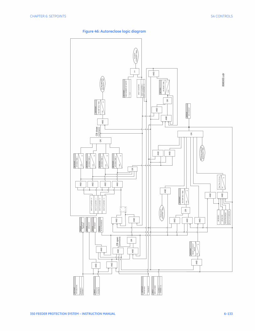
CHAPTER 6: SETPOINTS S4 CONTROLS
350 FEEDER PROTECTION SYSTEM – INSTRUCTION MANUAL 6–133
Figure 46: Autoreclose logic diagram
AN
D
SE
TP
OIN
T
RE
SE
TL
OC
KO
UT
DE
LA
Y
se
g
0
OR
INP
UT
AR
BL
OC
K
SE
TP
OIN
T
AR
FU
NC
TIO
N
Dis
ab
led
=0
En
ab
led
=1
STA
TU
S
AR
OU
TO
F
SE
RV
ICE
STA
TU
S
AR
BL
OC
K
STA
TU
S
AR
RE
AD
Y
STA
TU
S
AR
INP
RO
GR
ES
S
SE
TP
OIN
T
AR
INIT
IAT
E
Dis
ab
led
=0
INP
UT
BR
KC
LO
SE
D
CL
OS
ED
=1
AN
D
AN
D
AN
D
AN
D
SE
TP
OIN
T
INC
OM
PS
EQ
.T
IME
: 0
AN
D
AN
D
AN
D
AN
D
AN
D
OR
OR
AN
D
AN
D
AN
D
AR
RE
AD
Y
AR
INP
RO
GR
ES
S
AR
OU
TO
FS
ER
VIC
E
AR
BL
OC
K
QQS
ET
CLR
S R
AN
D
AN
D
AN
D
AN
D
SE
TP
OIN
T
AR
DE
AD
TIM
E1
t,se
c
0
SE
TP
OIN
T
AR
DE
AD
TIM
E2
0
SE
TP
OIN
T
AR
DE
AD
TIM
E3
0
SE
TP
OIN
T
AR
DE
AD
TIM
E4
0
OR
OR
AN
D
AN
D
AN
D
SE
TP
OIN
T
INC
OM
PS
EQ
.T
IME
:
0
AN
D
AN
D
OR
SE
TT
ING
AR
RE
SE
TT
IME 0
AN
D
SE
TP
OIN
T
MA
XN
UM
BE
RO
FS
HO
TS
1..
4
>=
SH
OT
CO
UN
TE
R
SH
OT
CO
UN
TE
R+
+
SH
OT
CO
UN
TE
R=
0
SH
OT
CO
UN
TE
R=
0
SH
OT
CO
UN
TE
R=
1
SH
OT
CO
UN
TE
R=
2
SH
OT
CO
UN
TE
R=
3
CB
clo
se
STA
TU
S
AR
LO
CK
OU
T
FR
OM
INC
OM
PLE
TE
SE
QU
EN
CE
TIM
E
TO
INC
OM
PLE
TE
SE
QU
EN
CE
TIM
E
OP
EN
ED
=0
AN
D
Ta
sk
Tim
e(5
-10
ms)
ms
0
FR
OM
SH
OT
CO
UN
TE
R=
MA
X
TO
SH
OT
CO
UN
TE
R=
MA
X
CB
open
(co
mm
an
d)
(co
mm
an
d)
Dis
ab
led
=0
t,se
c
t,se
c
t,se
c
t,se
c
t,se
c
t,se
c
898000.c
dr

6–134 350 FEEDER PROTECTION SYSTEM – INSTRUCTION MANUAL
S4 CONTROLS CHAPTER 6: SETPOINTS
The Automatic Reclosure function is designed to perform up to four breaker autoreclosings, with a configurable dead time before each reclosing shot. Upon AR function enabled, and breaker status “closed”, the AR is set into “AR Ready” state. If an intermittent feeder fault occurs such as overhead conductor touching tree branch, one or more of the overcurrent protection elements enabled under AR initiate menu will operate and issue a breaker trip command. If the breaker opens, the dead time configured under the first AR shot will start timing out. After this time expires, the AR scheme will produce the first breaker reclosing shot. Upon breaker close and no fault conditions, the overcurrent elements set for initiation on the first AR shot will not operate, and the reclosing is declared successful. The remaining of the configured AR sequence will be executed. The AR Reset time will start timing out, where upon time expiry resets the AR counter. The AR sequence is reset with AR function into “AR Ready” state.If the fault is permanent, the configured AR sequence will be executed in full, where the breaker opens after the last reclosing shot and the AR function goes into lockout. The reclosure scheme passes through the following states during operation:AR NOT READY: When in this state, the AR is blocked. The AR NOT READY occurs if any of the following conditions are present:• The maximum shot number was reached.• The incomplete sequence AR INCOM SEQ TIME timer times out.• The AR BLOCK INPUT is setAR READY: To reach this state the AR RESET NOT READY timer times out from NOT READY state or the AR RESET TIME timer times out from WAIT RST TIME state. In this state the autorecloser is waiting for reclose Initiation (RI) event to start the reclosure process.WAIT FOR 52 OPEN: Once a Reclose Initiation event occurs the autorecloser is waiting for breaker status OPEN or otherwise the AR INCOM SEQ TIME timer will time out. If the AR INCOM SEQ TIME expires, the autorecloser will go into NOT READY state. However if the breaker opens, the AR scheme will start the configured DEAD TIME timer, and will be put into WAIT DEAD TIME state.WAIT DEAD TIME: In this state the autorecloser is waiting for the relevant AR DEAD TIME SHOT timer to time out. If during this time out the breaker status changes to CLOSE, a Reclose Initiation or an AR BLOCK input occurs the autorecloser process ends in a NOT READY state. If not, the WAIT FOR 52 CLOSE state is reached.WAIT FOR 52 CLOSE: In this state upon reclosing command, the autorecloser is waiting for the breaker to CLOSE. If the AR INCOM SEQ TIME timer times out or a new Reclose Initiation occurs and it’s the last shot then the autorecloser ends in a NOT READY state. If a new Reclose Initiation occurs and it is not the last from the programmed sequence, the autorecloser goes into the WAIT FOR 52 OPEN status.WAIT RESET TIME: In this state, when the AR RST TIME timer times out the number of shots is reset and the autorecloser goes into AR READY state waiting for a new AR execution.If the breaker status changes to OPEN or an AR BLOCK input occurs, or a new Reclose Initiation happens and it’s the last shot then the autorecloser ends in a NOT READY state. If a new Reclose Initiation different from the last shot occurs the autorecloser goes into the WAIT FOR 52 OPEN status for the next shot.Reclose Initiation is produced by a trip with the relevant permission enabled.
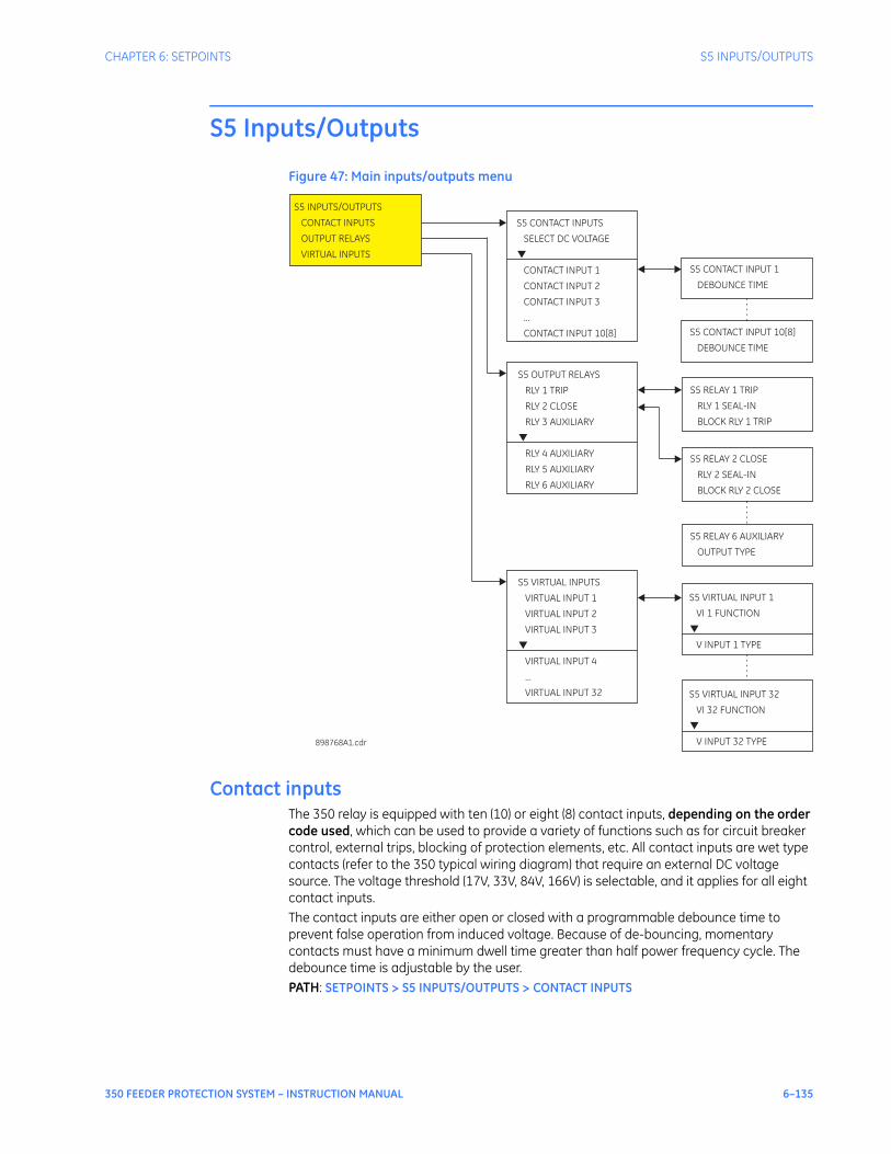
CHAPTER 6: SETPOINTS S5 INPUTS/OUTPUTS
350 FEEDER PROTECTION SYSTEM – INSTRUCTION MANUAL 6–135
S5 Inputs/Outputs
Figure 47: Main inputs/outputs menu
Contact inputsThe 350 relay is equipped with ten (10) or eight (8) contact inputs, depending on the order code used, which can be used to provide a variety of functions such as for circuit breaker control, external trips, blocking of protection elements, etc. All contact inputs are wet type contacts (refer to the 350 typical wiring diagram) that require an external DC voltage source. The voltage threshold (17V, 33V, 84V, 166V) is selectable, and it applies for all eight contact inputs. The contact inputs are either open or closed with a programmable debounce time to prevent false operation from induced voltage. Because of de-bouncing, momentary contacts must have a minimum dwell time greater than half power frequency cycle. The debounce time is adjustable by the user.PATH: SETPOINTS > S5 INPUTS/OUTPUTS > CONTACT INPUTS
S5 CONTACT INPUTS
SELECT DC VOLTAGE
CONTACT INPUT 1
CONTACT
CONTACT INPUT 3
...
CONTACT INPUT 10[8]
INPUT 2
▼
S5 INPUTS/OUTPUTS
CONTACT INPUTS
OUTPUT RELAYS
VIRTUAL INPUTS
898768A1.cdr
S5 OUTPUT RELAYS
RLY 1 TRIP
RLY 2 CLOSE
RLY 3 AUXILIARY
RLY 4 AUXILIARY
RLY 5 AUXILIARY
RLY 6 AUXILIARY
▼
S5 VIRTUAL INPUT 1
V INPUT 1 TYPE
VI 1 FUNCTION
▼
S5 VIRTUAL INPUTS
VIRTUAL INPUT 1
VIRTUAL INPUT 2
VIRTUAL INPUT 3
VIRTUAL INPUT 4
...
VIRTUAL INPUT 32
▼
S5 VIRTUAL INPUT 32
V INPUT 32 TYPE
VI 32 FUNCTION
▼
S5 RELAY 6 AUXILIARY
OUTPUT TYPE
S5 RELAY 2 CLOSE
RLY 2 SEAL-IN
BLOCK RLY 2 CLOSE
S5 RELAY 1 TRIP
RLY 1 SEAL-IN
BLOCK RLY 1 TRIP
S5 CONTACT INPUT 10[8]
DEBOUNCE TIME
S5 CONTACT INPUT 1
DEBOUNCE TIME
6–136 350 FEEDER PROTECTION SYSTEM – INSTRUCTION MANUAL
S5 INPUTS/OUTPUTS CHAPTER 6: SETPOINTS
SELECT DC VOLTAGE
Range: 17 V, 33 V, 84 V, 166 VDefault: 84 V
52a BKR INPUT 1
Range: Select alpha-numeric nameDefault: 52a (CI#1)
52b BKR INPUT 2
Range: Select alpha-numeric nameDefault: 52b (CI#2)
CONTACT INPUT X [3 to 10]
Range: Select alpha-numeric nameDefault: Input X
DEBOUNCE TIME
↘CONTACT INPUT X [1 TO 10]
Range: 1 to 64 msDefault: 2 ms
Each of the contact inputs 3 to 10[8], can be named to reflect the function it represents within the application. Up to 18 alpha-numeric characters are available for names. The debounce time is used to discriminate between oscillating inputs. The state will be recognized if the input is maintained for a period consisting of the protection pass plus the debounce setting.
NOTE
NOTE: Contact Input 1 and Contact Input 2 are named by the factory as 52a and 52b respectively and are used for monitoring the breaker open/close state when wired to the breakers auxiliary contacts 52a and 52b.
Output relaysThe 350 relay is equipped with seven electromechanical output relays: two special relays designated for Breaker Trip and Close (Relay 1 “Trip”, Relay 2 “Close”), four general purpose relays (Auxiliary Relays 3 to 6), and one Critical Failure relay for fail-safe relay indication. The special purpose relays have fixed operating characteristics and the general purpose relays can be configured by the user. Logic diagrams for each output relay are provided for detailed explanation of their operation.Operation of these breaker-control relays is designed to be controlled by the state of the circuit breaker as monitored by a 52a or 52b contact. • The Trip and Close relays reset after the breaker is detected in a state corresponding
to the command. When a relay feature sends a command to one of these special relays, it will remain operational until the requested change of breaker state is confirmed by a breaker auxiliary contact and the initiating condition has reset.
• If the initiating feature resets, but the breaker does not change state, the output relay will be reset after a default interval of 2 seconds.
• If neither of the breaker auxiliary contacts, 52a nor 52b, is programmed to a logic input, the Trip Relay is de-energized after either the delay programmed in the Breaker Failure feature, or a default interval of 100 ms after the initiating input resets. The Close Relay is de-energized after 200 ms.
• If a delay is programmed for the Trip or Close contact seal-in time, then this delay is added to the reset time. Note that the default setting for the seal-in time is 40 ms.

CHAPTER 6: SETPOINTS S5 INPUTS/OUTPUTS
350 FEEDER PROTECTION SYSTEM – INSTRUCTION MANUAL 6–137
Output Relay 1 "Trip" The following path is available using the keypad. For instructions on how to use the keypad, please refer to Chapter 3 - Working with the Keypad.PATH: SETPOINTS > S5 INPUTS/OUTPUTS > OUTPUT RELAYS > RELAY 1 TRIP
SEAL IN TIME
Range: 0.00 to 9.99 s in steps of 0.01Default: 0.04 s
This setting defines the time to be added to the reset time of the Relay 1 Trip output, thus extending its pulse width. This is useful for those applications where the 52 contacts reporting the breaker state are faster than the 52 contacts that are responsible for interrupting the coil current.
BLOCK RLY 1 TRIP
Range: Disabled, Contact Input 1 to 10[8], Virtual Input 1 to 32, Remote Input 1 to 32, Logic Elements 1 to 16Default: Disabled
This setting defines a block to the Trip Output relay. When the selected input is asserted, the Trip Output relay will be blocked.
52a Contact Configured
52b Contact Configured
Relay Operation
Yes Yes Trip Relay remains operational until 52b indicates an open breaker. Close Relay remains operational until 52a indicates a closed breaker.
Yes No Trip Relay remains operational until 52a indicates an open breaker. Close Relay remains operational until 52a indicates a closed breaker.
No Yes Trip Relay remains operational until 52b indicates an open breaker. Close Relay remains operational until 52b indicates a closed breaker.
No No Trip Relay operates until either the Breaker Failure delay expires (if the Breaker Failure element is enabled), or 100 ms after the feature causing the trip resets. Close Relay operates for 200 ms.
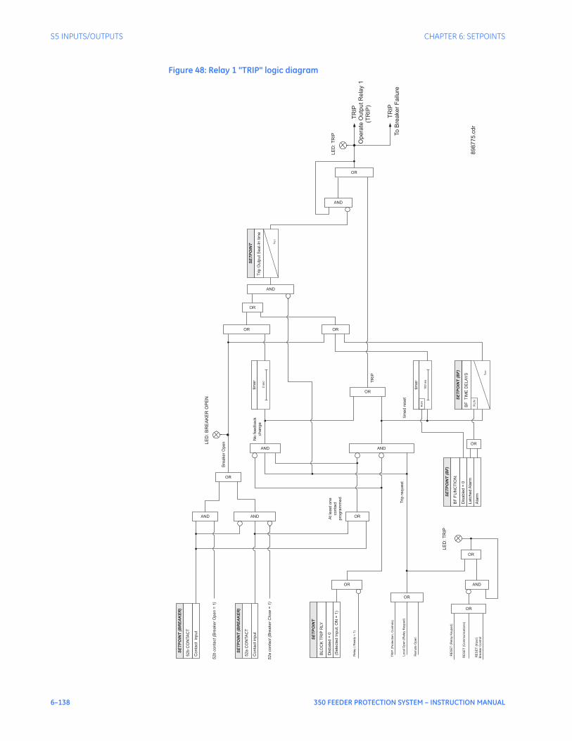
6–138 350 FEEDER PROTECTION SYSTEM – INSTRUCTION MANUAL
S5 INPUTS/OUTPUTS CHAPTER 6: SETPOINTS
Figure 48: Relay 1 "TRIP" logic diagram
TR
IP(P
rote
ctio
n,
Co
ntr
ols
)
Trip
req
ue
st
SE
TP
OIN
T(B
RE
AK
ER
)
52
bC
ON
TA
CT
Co
nta
ct
inp
ut
SE
TP
OIN
T(B
RE
AK
ER
)
52
aC
ON
TA
CT
Co
nta
ct
inp
ut
AND
OR
52
bco
nta
ct(B
rea
ke
rO
pe
n=
1)
AND
52
aco
nta
ct(B
rea
ke
rC
lose
=1
)
Bre
ake
rO
pe
n
OR
At
lea
st
on
e
co
nta
ct
pro
gra
mm
ed
AND
OR
TR
IP
No
fee
db
ack
ch
an
ge
OR
tim
ed
rese
t
SE
TP
OIN
T(B
F)
BF
FU
NC
TIO
N:
Dis
ab
led
=0
La
tch
ed
Ala
rm
Ala
rm
BF
TIM
ED
EL
AY
S
SE
TP
OIN
T(B
F)
RU
N
OR
OR
OR
AND
AND
Trip
Ou
tpu
tS
ea
l-In
tim
e
SE
TP
OIN
T
t RS
T
AND
LE
D:
TR
IP
OR
Lo
ca
lO
pe
n(R
ela
yK
eyp
ad
)
Re
mo
teO
pe
n
Re
lay
(R
ea
dy
=1
)
RE
SE
T(R
ela
yK
eyp
ad
)
RE
SE
T(C
om
mu
nic
atio
ns)
RE
SE
T(I
np
ut)
Bre
ake
rC
on
tro
l
OR
LE
D:
TR
IP
AND
OR
tim
er
10
0m
s
RU
N
OR
t RS
T
SE
TP
OIN
T
BL
OC
KT
RIP
RLY
Dis
ba
led
=0
(Se
lecte
dIn
pu
t,O
N=
1)
OR
tim
er
2se
c
LE
D:
BR
EA
KE
RO
PE
N
898775.c
dr
TR
IP
Op
era
teO
utp
ut
Re
lay
1
TR
IP
To
Bre
ake
rF
ailu
re
(TR
IP)

CHAPTER 6: SETPOINTS S5 INPUTS/OUTPUTS
350 FEEDER PROTECTION SYSTEM – INSTRUCTION MANUAL 6–139
Output Relay 2"Close"
PATH: SETPOINTS > S5 INPUTS/OUTPUTS > OUTPUT RELAYS > RELAY 2 CLOSE
SEAL IN TIME
Range: 0.00 to 9.99 s in steps of 0.01Default: 0.04 s
This setting defines the time to be added to the reset time of the Relay 2 Close output, thus extending its pulse width. This is useful for those applications where the 52 contacts reporting the breaker state are faster than the 52 contacts that are responsible for interrupting the coil current.
BLOCK RLY 2 CLOSE
Range: Disabled, Contact Input 1 to 10[8], Virtual Input 1 to 32, Remote Input 1 to 32, Logic Elements 1 to 16Default: Disabled
This setting defines a block to the Close Output relay. When the selected input is asserted, the Close Output relay will be blocked. The block function can be useful for breaker maintenance purposes.
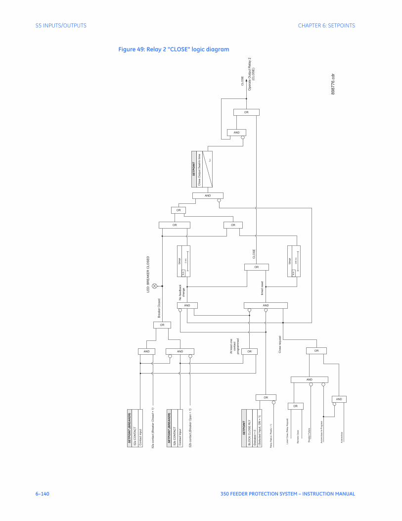
6–140 350 FEEDER PROTECTION SYSTEM – INSTRUCTION MANUAL
S5 INPUTS/OUTPUTS CHAPTER 6: SETPOINTS
Figure 49: Relay 2 "CLOSE" logic diagram
Clo
se
request
SE
TP
OIN
T(B
RE
AK
ER
)
52a
CO
NTA
CT
Conta
ctin
put
SE
TP
OIN
T(B
RE
AK
ER
)
52b
CO
NTA
CT
Conta
ctin
put
AND
OR
52
aco
nta
ct(B
rea
ke
rC
lose
d=
1)
AND
52b
conta
ct(B
reaker
Open
=1)
Bre
aker
Clo
sed
OR
Atle
astone
conta
ct
pro
gra
mm
ed
AND
OR
CLO
SE
No
feedback
change
OR
tim
ed
reset
OR
OR
OR
AND
AND
Clo
se
Outp
utS
eal-In
tim
e
SE
TP
OIN
T
t RS
T
AND
CLO
SE
Op
era
teO
utp
ut
Re
lay
2
(CL
OS
E)
OR
Lo
ca
lC
lose
(Re
lay
Ke
yp
ad
)
Re
mo
teC
lose
Re
lay
Sta
tus
(R
ea
dy
=1)
tim
er
20
0m
s
RU
N
SE
TP
OIN
T
BLO
CK
CLO
SE
RLY
Dis
bale
d=
0
(Se
lecte
dIn
pu
t,O
N=
1)
OR
AND
Bre
ake
rF
ailu
re
Au
tore
clo
se
In-P
rog
ress
AND
Au
tore
clo
se
OR
tim
er
2se
c
RU
N
LE
D:B
RE
AK
ER
CL
OS
ED
89
87
76
.cd
r
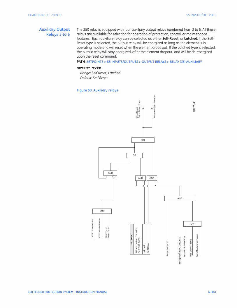
CHAPTER 6: SETPOINTS S5 INPUTS/OUTPUTS
350 FEEDER PROTECTION SYSTEM – INSTRUCTION MANUAL 6–141
Auxiliary OutputRelays 3 to 6
The 350 relay is equipped with four auxiliary output relays numbered from 3 to 6. All these relays are available for selection for operation of protection, control, or maintenance features. Each auxiliary relay can be selected as either Self-Reset, or Latched. If the Self-Reset type is selected, the output relay will be energized as long as the element is in operating mode and will reset when the element drops out. If the Latched type is selected, the output relay will stay energized, after the element dropout, and will be de-energized upon the reset command. PATH: SETPOINTS > S5 INPUTS/OUTPUTS > OUTPUT RELAYS > RELAY 3(6) AUXILIARY
OUTPUT TYPE
Range: Self Reset, LatchedDefault: Self Reset
Figure 50: Auxiliary relays
Fro
mP
rote
ctio
nF
ea
ture
OR
Fro
mC
on
tro
lF
ea
ture
Fro
mM
ain
ten
an
ce
Fe
atu
re
assig
ne
da
ux.
ou
tpu
ts:
AND
Re
lay(R
ea
dy
=1
)
SE
TP
OIN
T
RE
LA
Y(3
-6)
AU
XIL
IAR
Y
OU
TP
UT
TY
PE
Latc
hed
Self-R
eset
AND AND
OR
AND
OR
RE
SE
T(R
ela
yK
eyp
ad
)
RE
SE
T(C
om
mu
nic
atio
ns)
RE
SE
T(I
np
ut)
Bre
aker
Contr
ol
OR
Op
era
teA
ux
Ou
tpu
tR
ela
y(3-
6)
Me
ssa
ge
&E
ve
nt
Re
co
rde
r
898777.c
dr

6–142 350 FEEDER PROTECTION SYSTEM – INSTRUCTION MANUAL
S5 INPUTS/OUTPUTS CHAPTER 6: SETPOINTS
Critical Failure Relay#7
The 350 relay is also equipped with one output relay (# 7 - “Critical Failure Relay”) for fail-safe indication. There are no user-programmable setpoints associated with this output relay. The logic for this relay is shown below.The Critical Failure Relay (Output Relay 7) is a form C contact (refer to the Typical Wiring Diagram) with one NO and one NC contacts (no control power). Output relay 7 is energized or de-energized (state change) depending on the following conditions:
1. Output Relay 7 will be de-energized, if the relay is not IN-SERVICE or the control power is not applied to the relay
2. Output Relay 7 will be energized when the control power is applied to the relay and the relay is IN-SERVICE mode.
3. Output Relay 7 will stay de-energized, when the control power is applied, if the relay was not programmed as “Ready”, or upon major self-test failure during relay boot up.
4. Output Relay 7 will change state from energized to de-energized if the 350 relay experiences any major self-test failure.
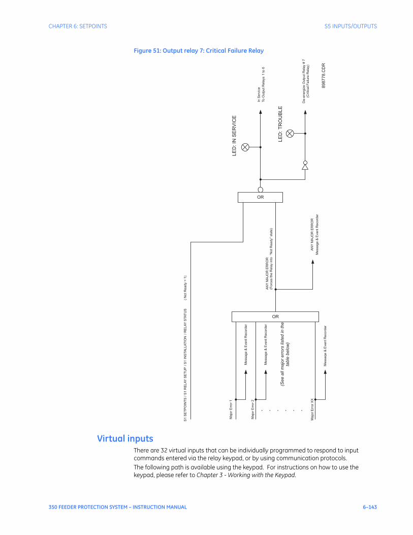
CHAPTER 6: SETPOINTS S5 INPUTS/OUTPUTS
350 FEEDER PROTECTION SYSTEM – INSTRUCTION MANUAL 6–143
Figure 51: Output relay 7: Critical Failure Relay
Virtual inputsThere are 32 virtual inputs that can be individually programmed to respond to input commands entered via the relay keypad, or by using communication protocols.The following path is available using the keypad. For instructions on how to use the keypad, please refer to Chapter 3 - Working with the Keypad.
AN
YM
AJO
RE
RR
OR
(Fo
rce
sth
eR
ela
yin
to“N
ot
Re
ad
y”
sta
te)
OR
S1
SE
TP
OIN
TS
/S
1R
ELA
YS
ET
UP
/S
1IN
STA
LLA
TIO
N/
RE
LA
YS
TA
TU
S(
No
tR
ea
dy
=1
)
LE
D:IN
SE
RV
ICE
Me
ssa
ge
&E
ve
nt
Re
co
rde
r
AN
YM
AJO
RE
RR
OR
OR
. . . . . .
Me
ssa
ge
&E
ve
nt
Re
co
rde
r
Me
ssa
ge
&E
ve
nt
Re
co
rde
r
Me
ssa
ge
&E
ve
nt
Re
co
rde
r
Ma
jor
Err
or
1
Ma
jor
Err
or
2
Ma
jor
Err
or
XX
(See
all
majo
rerr
ors
liste
din
the
table
belo
w)
To
Ou
tpu
tR
ela
ys
1to
6
InS
erv
ice
De
-en
erg
ize
Ou
tpu
tR
ela
y#
7
(Critica
lF
ailu
reR
ela
y)
LE
D:
TR
OU
BLE
898778.C
DR

6–144 350 FEEDER PROTECTION SYSTEM – INSTRUCTION MANUAL
S5 INPUTS/OUTPUTS CHAPTER 6: SETPOINTS
PATH: SETPOINTS > S5 INPUTS/OUTPUTS > VIRTUAL INPUTS
VI x FUNCTION
Range: Disabled/EnabledDefault: Disabled
The Virtual Input is enabled and ready to be triggered when set to Enabled. All virtual inputs will appear under the S4 CONTROLS > SETPOINTS > S4 VIRTUAL INPUTS menu.
VI x TYPE
Range: Self-Reset, LatchedDefault: Self-reset
When the Self-Reset type is selected, the Virtual Input will be evaluated for one protection pass only, upon “On” initiation and it will reset. When the Latched type is selected, the virtual input will keep the state “On” until reset command “Off” is initiated.
NOTE
NOTE: See also the Virtual Inputs section under S4 CONTROLS, on how to trigger a virtual input signal state.
Virtual input programming begins with enabling the Virtual Input Function, and selecting the Virtual Input Type Self-Reset or Latched under SETPOINTS > S5 INPUTS/OUTPUTS > VIRTUAL INPUTS. Next, the user can assign a command On/Off to the enabled Virtual Input under SETPOINTS > S4 CONTROLS > S4 VIRTUAL INPUTS. Referring to the Virtual Inputs logic diagram below, a Virtual Input type can be selected to be either Self-Reset, or Latched. When Self-Reset is selected and the “On” command is executed, the virtual input is evaluated as a pulse at a rate of one protection pass. To prolong the time of the virtual input pulse, one can assign it as a trigger source to a logic element with a dropout timer set to the desired pulse time. Selecting the Latched type, will latch the virtual input state, when the “On” command is executed.
NOTE
NOTE: The "On" state of the Virtual Input will not be retained in the case of cycling of the relay control power supply.
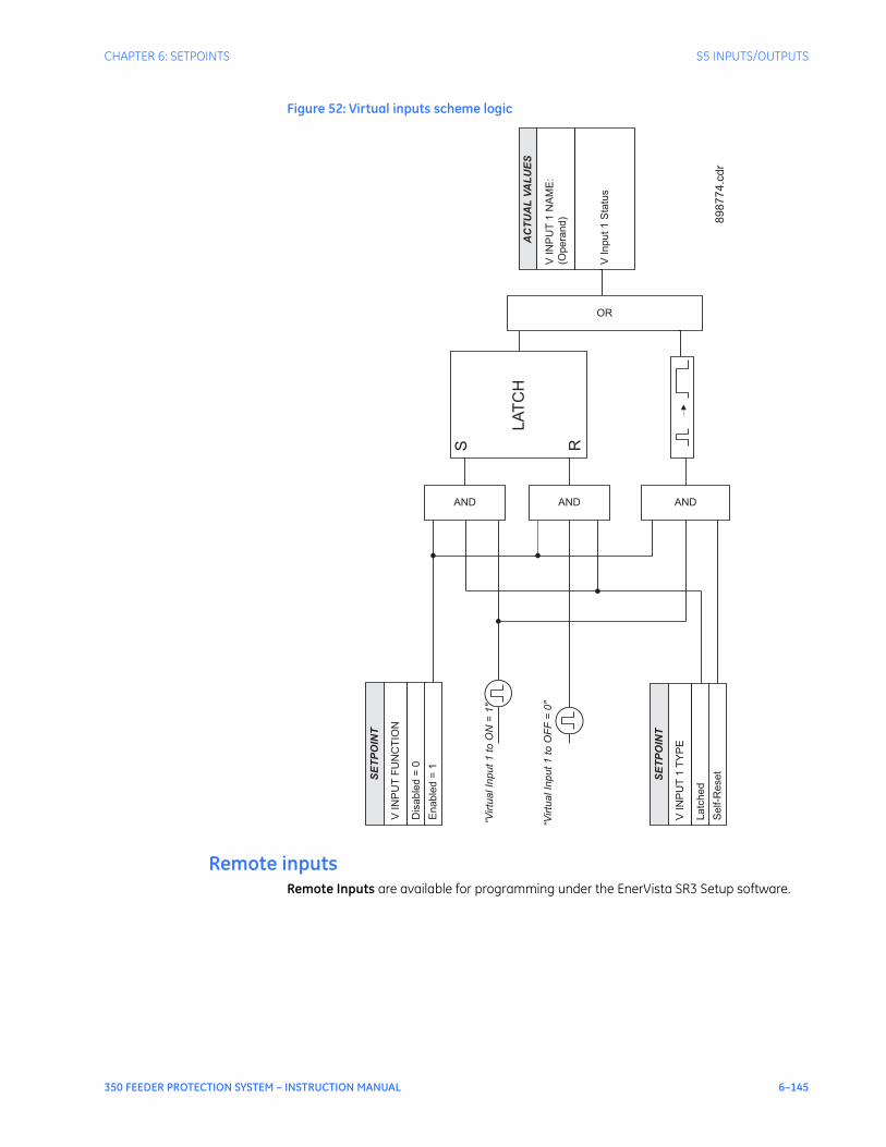
CHAPTER 6: SETPOINTS S5 INPUTS/OUTPUTS
350 FEEDER PROTECTION SYSTEM – INSTRUCTION MANUAL 6–145
Figure 52: Virtual inputs scheme logic
Remote inputsRemote Inputs are available for programming under the EnerVista SR3 Setup software.
SE
TP
OIN
T
VIN
PU
TF
UN
CT
ION
Dis
able
d=
0
Enable
d=
1
AND
SE
TP
OIN
T
VIN
PU
T1
TY
PE
Latc
hed
Self-R
eset
AND AND
“Virtu
alIn
put1
toO
N=
1"
“Virtu
alIn
put1
toO
FF
=0"
S R
LA
TC
H
OR
AC
TU
AL
VA
LU
ES
VIN
PU
T1
NA
ME
:
(Opera
nd)
VIn
put1
Sta
tus
89
87
74
.cd
r

6–146 350 FEEDER PROTECTION SYSTEM – INSTRUCTION MANUAL
S5 INPUTS/OUTPUTS CHAPTER 6: SETPOINTS

350 FEEDER PROTECTION SYSTEM – INSTRUCTION MANUAL 7–1
350 Feeder Protection System
Chapter 7: Maintenance
Digital EnergyMultilin
Maintenance
Information about the relay and the breaker can be obtained through the features included in the Maintenance page.
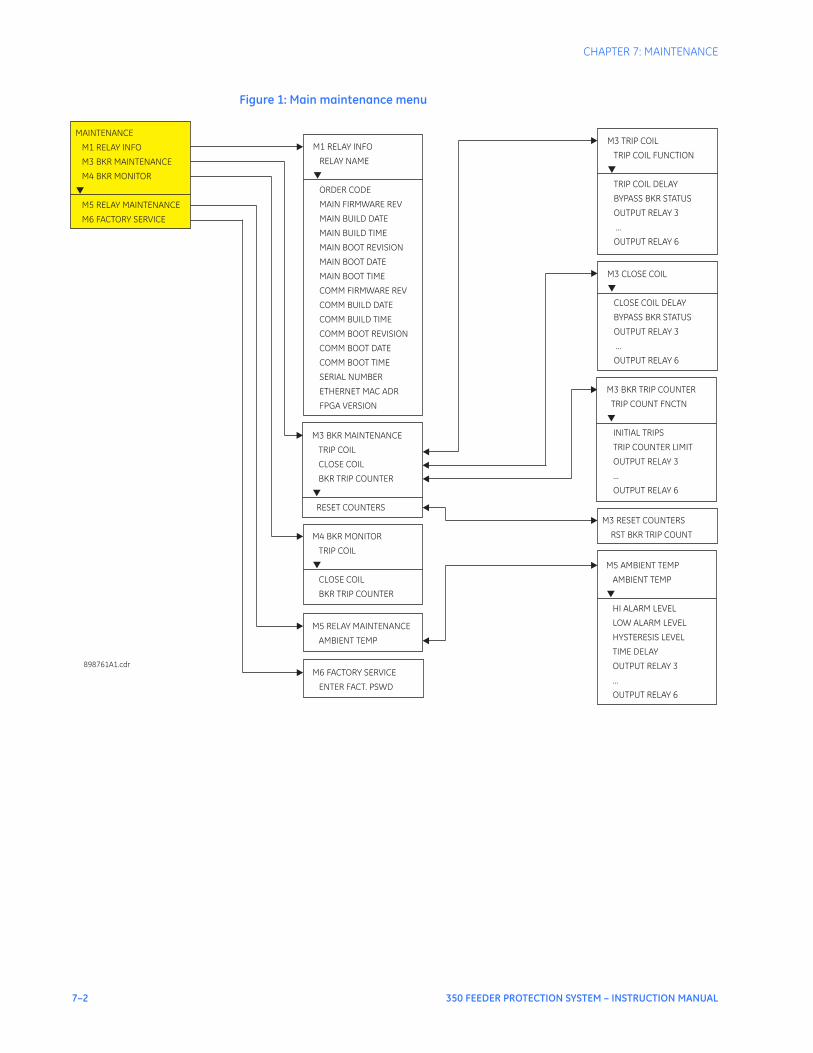
7–2 350 FEEDER PROTECTION SYSTEM – INSTRUCTION MANUAL
CHAPTER 7: MAINTENANCE
Figure 1: Main maintenance menu
M6 FACTORY SERVICE
ENTER FACT. PSWD
M4 BKR MONITOR
TRIP COIL
CLOSE COIL
BKR TRIP COUNTER
▼
M1 RELAY INFO
RELAY NAME
ORDER CODE
MAIN FIRMWARE REV
MAIN BUILD DATE
MAIN BUILD TIME
MAIN BOOT REVISION
MAIN BOOT DATE
MAIN BOOT TIME
COMM FIRMWARE REV
COMM BUILD DATE
COMM BUILD TIME
COMM BOOT REVISION
COMM BOOT DATE
COMM BOOT TIME
SERIAL NUMBER
ETHERNET MAC ADR
FPGA VERSION
▼
MAINTENANCE
M1 RELAY INFO
M3 BKR MAINTENANCE
M5 RELAY MAINTENANCE
M6 FACTORY SERVICE
M4 BKR MONITOR
▼
M3 TRIP COIL
TRIP COIL FUNCTION
TRIP COIL DELAY
BYPASS BKR STATUS
OUTPUT RELAY 3
...
OUTPUT RELAY 6
▼
898761A1.cdr
M3 BKR MAINTENANCE
TRIP COIL
CLOSE COIL
BKR TRIP COUNTER
RESET COUNTERS
▼
M3 RESET COUNTERS
RST BKR TRIP COUNT
M3 BKR TRIP COUNTER
TRIP COUNT FNCTN
INITIAL TRIPS
TRIP COUNTER LIMIT
OUTPUT RELAY 3
...
OUTPUT RELAY 6
▼
M3 CLOSE COIL
CLOSE COIL DELAY
BYPASS BKR STATUS
OUTPUT RELAY 3
...
OUTPUT RELAY 6
▼
M5 RELAY MAINTENANCE
AMBIENT TEMP
M5 AMBIENT TEMP
AMBIENT TEMP
LOW ALARM LEVEL
HYSTERESIS LEVEL
TIME DELAY
...
OUTPUT RELAY 6
HI ALARM LEVEL
OUTPUT RELAY 3
▼

CHAPTER 7: MAINTENANCE M1 RELAY INFORMATION
350 FEEDER PROTECTION SYSTEM – INSTRUCTION MANUAL 7–3
M1 Relay information
PATH: MAINTENANCE > M1 RELAY INFO
RELAY NAME
Range: alpha-numeric name of up to 18 characters Default: Feeder Name
ORDER CODE
350-CP5G5HSMCPZEDN
This screen shows the relay Order Code.
FIRMWARE REVISION
1.10
This screen shows the relay Firmware Revision.
BUILD DATE
Feb 18 2009
This screen shows the relay Firmware Build Date.
BUILD TIME
17:13:42This screen shows the relay Firmware Build Time.
BOOT REVISION
1.00This screen shows the relay Boot Code Revision.
SERIAL NUMBER
ML0T08000063
Each 350 relay has a unique serial number.
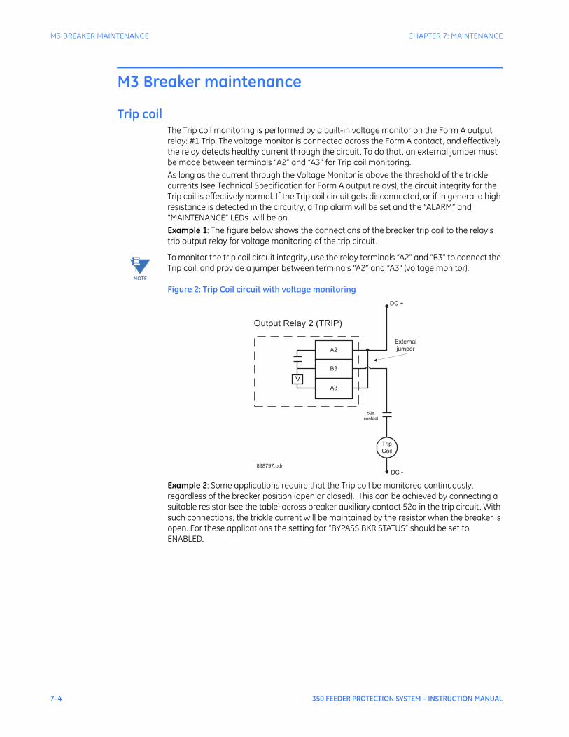
7–4 350 FEEDER PROTECTION SYSTEM – INSTRUCTION MANUAL
M3 BREAKER MAINTENANCE CHAPTER 7: MAINTENANCE
M3 Breaker maintenance
Trip coilThe Trip coil monitoring is performed by a built-in voltage monitor on the Form A output relay: #1 Trip. The voltage monitor is connected across the Form A contact, and effectively the relay detects healthy current through the circuit. To do that, an external jumper must be made between terminals “A2” and “A3” for Trip coil monitoring. As long as the current through the Voltage Monitor is above the threshold of the trickle currents (see Technical Specification for Form A output relays), the circuit integrity for the Trip coil is effectively normal. If the Trip coil circuit gets disconnected, or if in general a high resistance is detected in the circuitry, a Trip alarm will be set and the “ALARM” and “MAINTENANCE” LEDs will be on. Example 1: The figure below shows the connections of the breaker trip coil to the relay’s trip output relay for voltage monitoring of the trip circuit.
NOTE
NOTE: To monitor the trip coil circuit integrity, use the relay terminals “A2” and “B3” to connect the Trip coil, and provide a jumper between terminals “A2” and “A3” (voltage monitor).
Figure 2: Trip Coil circuit with voltage monitoring
Example 2: Some applications require that the Trip coil be monitored continuously, regardless of the breaker position (open or closed). This can be achieved by connecting a suitable resistor (see the table) across breaker auxiliary contact 52a in the trip circuit. With such connections, the trickle current will be maintained by the resistor when the breaker is open. For these applications the setting for “BYPASS BKR STATUS” should be set to ENABLED.
External
jumper
V
A2
B3
A3
Trip
Coil
DC +
DC -
Output Relay 2 (TRIP)
52a
contact
898797.cdr
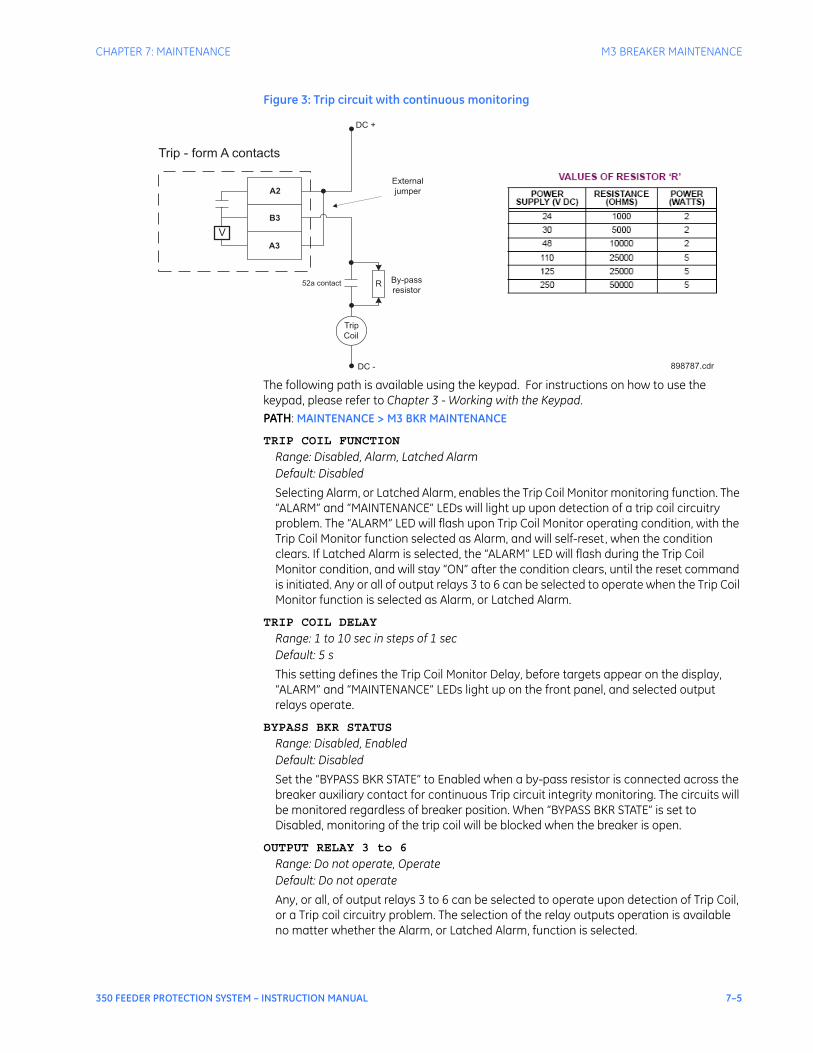
CHAPTER 7: MAINTENANCE M3 BREAKER MAINTENANCE
350 FEEDER PROTECTION SYSTEM – INSTRUCTION MANUAL 7–5
Figure 3: Trip circuit with continuous monitoring
The following path is available using the keypad. For instructions on how to use the keypad, please refer to Chapter 3 - Working with the Keypad.PATH: MAINTENANCE > M3 BKR MAINTENANCE
TRIP COIL FUNCTION
Range: Disabled, Alarm, Latched AlarmDefault: Disabled
Selecting Alarm, or Latched Alarm, enables the Trip Coil Monitor monitoring function. The “ALARM” and “MAINTENANCE” LEDs will light up upon detection of a trip coil circuitry problem. The “ALARM” LED will flash upon Trip Coil Monitor operating condition, with the Trip Coil Monitor function selected as Alarm, and will self-reset, when the condition clears. If Latched Alarm is selected, the “ALARM” LED will flash during the Trip Coil Monitor condition, and will stay “ON” after the condition clears, until the reset command is initiated. Any or all of output relays 3 to 6 can be selected to operate when the Trip Coil Monitor function is selected as Alarm, or Latched Alarm.
TRIP COIL DELAY
Range: 1 to 10 sec in steps of 1 secDefault: 5 s
This setting defines the Trip Coil Monitor Delay, before targets appear on the display, “ALARM” and “MAINTENANCE” LEDs light up on the front panel, and selected output relays operate.
BYPASS BKR STATUS
Range: Disabled, EnabledDefault: Disabled
Set the “BYPASS BKR STATE” to Enabled when a by-pass resistor is connected across the breaker auxiliary contact for continuous Trip circuit integrity monitoring. The circuits will be monitored regardless of breaker position. When “BYPASS BKR STATE” is set to Disabled, monitoring of the trip coil will be blocked when the breaker is open.
OUTPUT RELAY 3 to 6
Range: Do not operate, OperateDefault: Do not operate
Any, or all, of output relays 3 to 6 can be selected to operate upon detection of Trip Coil, or a Trip coil circuitry problem. The selection of the relay outputs operation is available no matter whether the Alarm, or Latched Alarm, function is selected.
Trip
Coil
DC -
RBy-pass
resistor52a contact
External
jumper
V
A2
B3
A3
DC +
Trip - form A contacts
898787.cdr
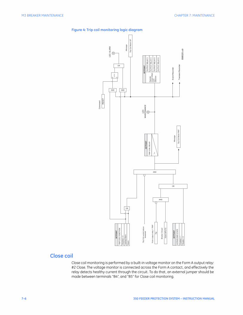
7–6 350 FEEDER PROTECTION SYSTEM – INSTRUCTION MANUAL
M3 BREAKER MAINTENANCE CHAPTER 7: MAINTENANCE
Figure 4: Trip coil monitoring logic diagram
Close coilClose coil monitoring is performed by a built-in voltage monitor on the Form A output relay: #2 Close. The voltage monitor is connected across the Form A contact, and effectively the relay detects healthy current through the circuit. To do that, an external jumper should be made between terminals “B4”, and “B5” for Close coil monitoring.
SE
TP
OIN
T
TR
IPC
OIL
FU
NC
TIO
N:
Dis
able
d=
0
Latc
hed
Ala
rm
Eve
nt
Re
co
rde
r
Tra
nsie
nt
Re
co
rde
r
Ala
rm
OR
OR
AND
SE
TP
OIN
T
Opera
te
outp
utre
lays
upon
sele
ction
OU
TP
UT
RE
LA
Y4
OU
TP
UT
RE
LA
Y5
OU
TP
UT
RE
LA
Y6
OU
TP
UT
RE
LA
Y3
Trip
Coil
Montr
OP
Message
Trip
Coil
curr
entabove
thre
shold
AND
OR
52a/b
INP
UT
S
Bre
aker
Clo
sed
Trip
Fro
moutp
utre
lay
1T
RIP
SE
TP
OIN
T
BY
PA
SS
BK
RS
TA
TE
Enable
d=
1
Dis
able
=0
AND
TR
IPC
OIL
DE
LA
Y:
SE
TP
OIN
T
t PK
P
LE
D:
MA
INT
EN
AN
CE
Trip
Coil
Montr
PK
P
Message
LE
D:A
LA
RM
RE
SE
T
Co
mm
an
d
AND
S R
LA
TC
H
898020.c
dr
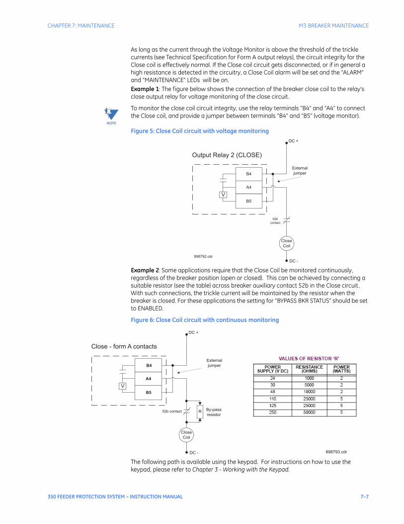
CHAPTER 7: MAINTENANCE M3 BREAKER MAINTENANCE
350 FEEDER PROTECTION SYSTEM – INSTRUCTION MANUAL 7–7
As long as the current through the Voltage Monitor is above the threshold of the trickle currents (see Technical Specification for Form A output relays), the circuit integrity for the Close coil is effectively normal. If the Close coil circuit gets disconnected, or if in general a high resistance is detected in the circuitry, a Close Coil alarm will be set and the “ALARM” and “MAINTENANCE” LEDs will be on. Example 1: The figure below shows the connection of the breaker close coil to the relay’s close output relay for voltage monitoring of the close circuit.
NOTE
NOTE: To monitor the close coil circuit integrity, use the relay terminals “B4” and “A4” to connect the Close coil, and provide a jumper between terminals “B4” and “B5” (voltage monitor).
Figure 5: Close Coil circuit with voltage monitoring
Example 2: Some applications require that the Close Coil be monitored continuously, regardless of the breaker position (open or closed). This can be achieved by connecting a suitable resistor (see the table) across breaker auxiliary contact 52b in the Close circuit. With such connections, the trickle current will be maintained by the resistor when the breaker is closed. For these applications the setting for “BYPASS BKR STATUS” should be set to ENABLED.
Figure 6: Close Coil circuit with continuous monitoring
The following path is available using the keypad. For instructions on how to use the keypad, please refer to Chapter 3 - Working with the Keypad.
External
jumper
V
B4
A4
B5
Close
Coil
DC +
DC -
Output Relay 2 (CLOSE)
52b
contact
898792.cdr
Close
Coil
DC -
RBy-pass
resistor52b contact
External
jumper
V
B4
B5
DC +
Close - form A contacts
898793.cdr
A4

7–8 350 FEEDER PROTECTION SYSTEM – INSTRUCTION MANUAL
M3 BREAKER MAINTENANCE CHAPTER 7: MAINTENANCE
PATH: MAINTENANCE > M3 BKR MAINTENANCE
CLOSE COIL FUNCTION
Range: Disabled, Alarm, Latched AlarmDefault: Disabled
Selecting Alarm, or Latched Alarm, enables the Close Coil Monitor monitoring function. The “ALARM” and “MAINTENANCE” LEDs will light up upon detection of a close coil circuitry problem. The “ALARM” LED will flash upon a Close Coil Monitor operating condition, with the Close Coil Monitor function selected as Alarm, and will self-reset, when the condition clears. If Latched Alarm is selected, the “ALARM” LED will flash during the Close Coil Monitor condition, and will stay “ON” after the condition clears, until the reset command is initiated. Any or all of output relays 3 to 6 can be selected to operate when the Close Coil Monitor function is selected as Alarm, or Latched Alarm.
CLOSE COIL DELAY
Range: 1 to 10 sec in steps of 1 secDefault: 5 s
This setting defines the Close Coil Monitor Delay, before targets appear on the display, “ALARM” and “MAINTENANCE” LEDs light up on the front panel, and selected output relays operate.
BYPASS BKR STATUS
Range: Disabled, EnabledDefault: Disabled
Set the “BYPASS BKR STATE” to Enabled when a by-pass resistor is connected across the breaker auxiliary contact for continuous Close circuit integrity monitoring. The circuits will be monitored regardless of breaker position. When “BYPASS BKR STATE” is set to Disabled, monitoring of the close coil will be blocked when the breaker is closed.
OUTPUT RELAY 3 to 6
Range: Do not operate, OperateDefault: Do not operate
Any, or all, of output relays 3 to 6 can be selected to operate upon detection of a Close coil circuitry problem. The selection of the relay outputs operation is available no matter whether the Alarm, or Latched Alarm, function is selected.
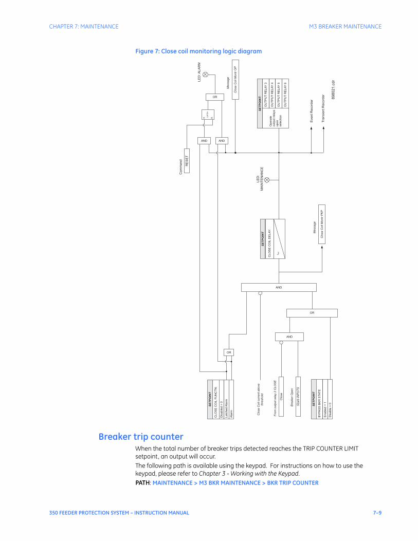
CHAPTER 7: MAINTENANCE M3 BREAKER MAINTENANCE
350 FEEDER PROTECTION SYSTEM – INSTRUCTION MANUAL 7–9
Figure 7: Close coil monitoring logic diagram
Breaker trip counterWhen the total number of breaker trips detected reaches the TRIP COUNTER LIMIT setpoint, an output will occur.The following path is available using the keypad. For instructions on how to use the keypad, please refer to Chapter 3 - Working with the Keypad.PATH: MAINTENANCE > M3 BKR MAINTENANCE > BKR TRIP COUNTER
SE
TP
OIN
T
CLO
SE
CO
ILF
UN
CT
N:
Dis
able
d=
0
Latc
hed
Ala
rm
EventR
ecord
er
Tra
nsie
ntR
ecord
er
Ala
rm
OR
OR
AND
SE
TP
OIN
T:
Opera
te
outp
utre
lays
upon
sele
ction
OU
TP
UT
RE
LA
Y4
OU
TP
UT
RE
LA
Y5
OU
TP
UT
RE
LA
Y6
OU
TP
UT
RE
LA
Y3
Clo
se
Coil
Montr
OP
Message
Clo
se
Coil
curr
entabove
thre
shold
AND
OR
52a/b
INP
UT
S
Bre
aker
Open
Clo
se
Fro
moutp
utre
lay
2C
LO
SE
SE
TP
OIN
T
BY
PA
SS
BK
RS
TA
TE
Enable
d=
1
Dis
able
=0
AND
CLO
SE
CO
ILD
ELA
Y:
SE
TP
OIN
T
t PK
P
LE
D:
MA
INT
EN
AN
CE
Clo
se
Coil
Montr
PK
P
Message
LE
D:A
LA
RM
RE
SE
T
Com
mand
AND
S R
LA
TC
H
898021.c
dr
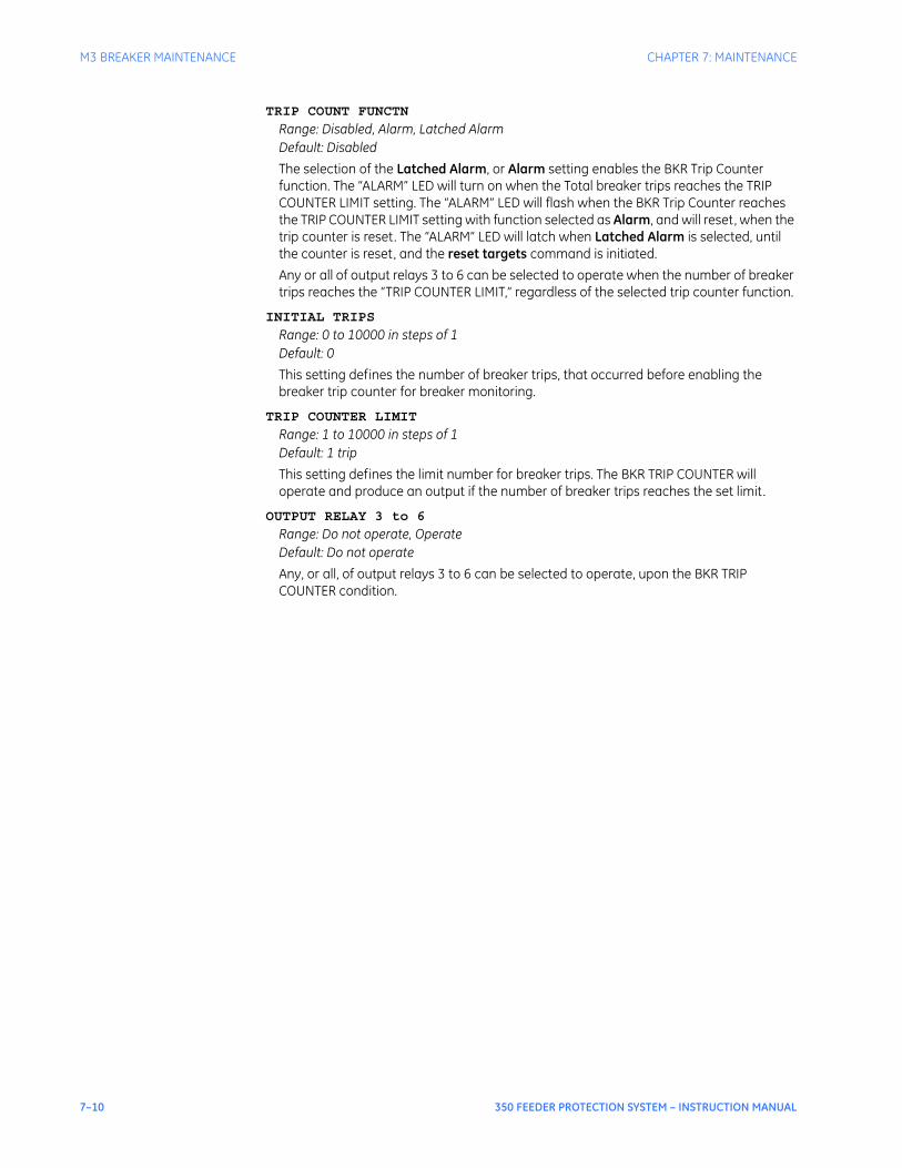
7–10 350 FEEDER PROTECTION SYSTEM – INSTRUCTION MANUAL
M3 BREAKER MAINTENANCE CHAPTER 7: MAINTENANCE
TRIP COUNT FUNCTN
Range: Disabled, Alarm, Latched AlarmDefault: Disabled
The selection of the Latched Alarm, or Alarm setting enables the BKR Trip Counter function. The “ALARM” LED will turn on when the Total breaker trips reaches the TRIP COUNTER LIMIT setting. The “ALARM” LED will flash when the BKR Trip Counter reaches the TRIP COUNTER LIMIT setting with function selected as Alarm, and will reset, when the trip counter is reset. The “ALARM” LED will latch when Latched Alarm is selected, until the counter is reset, and the reset targets command is initiated.Any or all of output relays 3 to 6 can be selected to operate when the number of breaker trips reaches the “TRIP COUNTER LIMIT,” regardless of the selected trip counter function.
INITIAL TRIPS
Range: 0 to 10000 in steps of 1Default: 0
This setting defines the number of breaker trips, that occurred before enabling the breaker trip counter for breaker monitoring.
TRIP COUNTER LIMIT
Range: 1 to 10000 in steps of 1Default: 1 trip
This setting defines the limit number for breaker trips. The BKR TRIP COUNTER will operate and produce an output if the number of breaker trips reaches the set limit.
OUTPUT RELAY 3 to 6
Range: Do not operate, OperateDefault: Do not operate
Any, or all, of output relays 3 to 6 can be selected to operate, upon the BKR TRIP COUNTER condition.
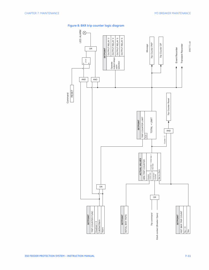
CHAPTER 7: MAINTENANCE M3 BREAKER MAINTENANCE
350 FEEDER PROTECTION SYSTEM – INSTRUCTION MANUAL 7–11
Figure 8: BKR trip counter logic diagram
TO
TA
L=
LIM
IT
OR
RU
N
SE
TP
OIN
T
EventR
ecord
er
Tra
nsie
ntR
ecord
er
SE
TP
OIN
T
Op
era
te
ou
tpu
tre
lays
up
on
se
lectio
n
OU
TP
UT
RE
LA
Y4
OU
TP
UT
RE
LA
Y5
OU
TP
UT
RE
LA
Y6
OU
TP
UT
RE
LA
Y3
Trip
Co
un
ter
PK
P
Trip
Co
un
ter
Re
se
t
Trip
Co
un
ter
OP
Me
ssa
ge
SE
TP
OIN
T
TR
IPC
OU
NT
ER
FU
NC
Dis
ab
led
=0
La
tch
ed
Ala
rm
Ala
rm
OR
OR
AND
Trip
co
mm
an
d
52
a/b
co
nta
ct(B
rea
ke
rO
pe
n)
INIT
IAL
BK
RT
RIP
S
SE
TP
OIN
T
Incre
ment
Counte
r
TR
IPC
OU
NT
ER
LIM
ITB
RK
TR
IPC
OU
NT
ER
AC
TU
AL
VA
LU
ES
Bre
aker
Initia
ltr
ips
Counte
r=
Initia
ltr
ips
+
new
trip
s
RS
TB
KR
TR
IPC
OU
NT
SE
TP
OIN
T
No
=0
Ye
s
Se
tto
Ze
ro
AND
Counte
r=
0
RE
SE
T
Com
mand
AND
S R
LA
TC
H
89
87
73
.cd
r
LE
D:A
LA
RM

7–12 350 FEEDER PROTECTION SYSTEM – INSTRUCTION MANUAL
M4 BREAKER MONITOR CHAPTER 7: MAINTENANCE
M4 Breaker monitor
The status of the breaker trip and close coils, as well as the trip and close circuits, can be monitored under MAINTENANCE > M4 BKR MONITOR. In the case where a breaker coil or circuit fails, the relay will display the message "Unhealthy" for the corresponding coil.Further information on the breaker is provided under BKR TRIP COUNTER, where the 350 stores the number of trips. The counter can be reset under M3 RESET COUNTERS > RST BKR TRIP COUNT set to "Yes".PATH: MAINTENANCE > M4 BKR MONITOR
TRIP COIL
Healthy
Range: Healthy, Unhealthy
CLOSE COIL
Healthy
Range: Healthy, Unhealthy
BKR TRIP COUNTER
5
Number of Trips

CHAPTER 7: MAINTENANCE M5 RELAY MAINTENANCE
350 FEEDER PROTECTION SYSTEM – INSTRUCTION MANUAL 7–13
M5 Relay maintenance
Ambient temperatureThe SR3 has a temperature monitor feature that measures the ambient temperature around the chassis of the relay. The relay extrapolates the ambient temperature from an internal temperature sensor inside the product. This feature can be used to signal the customer that the product is being subjected to temperatures that can degrade the product life and proper action should be initiated. For example the air conditioning, heating or ventilation system should be checked. The purpose of the feature is to measure the immediate temperature around the product. There are several factors that can alter the measurement that need to be considered for the application of this feature.• Any forced air flow or obstructions that can interrupt even distribution of the ambient
temperature.• Installation of the relay should be for normal operation (CT, VT, inputs, outputs).PATH: MAINTENANCE > M5 RELAY MAINTENANCE > AMBIENT TEMP
AMBIENT TEMPERATURE
Range: Disabled, Alarm, Latched AlarmDefault: Disabled
This setting enables the ambient temperature functionality. If the operating condition is satisfied when Alarm is selected as the function, the “ALARM” LED will flash upon the activating condition, and will automatically reset when the condition clears. If Latched Alarm is selected, the LED “ALARM” will flash upon the activating condition, and will stay “ON” after the condition clears, until a reset command is initiated. Any assignable output relays can be selected to operate when this function is enabled.
HI ALARM LEVEL
Range: 20°C to 80°C in steps of 1°CDefault: 60°C
This setting specifies the temperature level monitored by the Ambient Temperature Alarm high logic. The alarm will occur when the temperature remains above this level.
LOW ALARM LEVEL
Range: -40°C to 20°C in steps of 1°CDefault: 10°C
This setting specifies the temperature level monitored by the Ambient Temperature Alarm low logic. The alarm will occur when the temperature remains below this level.
HYSTERESIS LEVEL
Range: 2°C to 10°C in steps of 1°CDefault: 2°C
This setting allows the user to select the dropout level for the feature.
TIME DELAY
Range: 1 to 60 min in steps of 1 minDefault: 1 sec
This timer starts when either the high or low level thresholds have exceeded their respective levels.

7–14 350 FEEDER PROTECTION SYSTEM – INSTRUCTION MANUAL
M5 RELAY MAINTENANCE CHAPTER 7: MAINTENANCE
OUTPUT RELAY 3 to 6
Range: Do Not Operate, OperateDefault: Do Not Operate
Any assignable output relay can be selected to operate upon Ambient Temperature Alarm operation.
CHAPTER 7: MAINTENANCE M5 RELAY MAINTENANCE
350 FEEDER PROTECTION SYSTEM – INSTRUCTION MANUAL 7–15
Figure 9: Ambient Temperature Alarm logic diagram
SE
TT
ING
S
SE
TT
ING
RU
N
LA
TCH
S R
LOG
ICO
PE
RA
ND
Am
bTe
mp
HI
Ala
rmP
KP
An
yA
larm
OP
TAR
GE
TM
ES
SA
GE
Am
bTe
mp
HI
Ala
rmS
tate
: Pic
kup
89
87
79
.cd
r
Am
bTe
mp
HI
Ala
rmO
P
AM
BT
EM
PA
LA
RM
Ala
rm
Latc
he
dA
larm
AM
BT
EM
PA
LA
RM
Hi A
larm
Lev
el
Low
Ala
rmLe
ve
l
T>
Hig
hTe
mp
T<
Low
Tem
p
RU
N
OR
Am
bTe
mp
HI
Ala
rmS
tate
: Op
era
te
AN
D
AN
D
INP
UT
S
Em
erg
en
cy
Re
sta
rtIn
pu
t
Loc
kou
tR
ese
tIn
pu
t
SE
TT
ING
S
Off
=0
Loc
kou
tR
ese
t
Off
=0
Em
erg
en
cy
Re
sta
rt
S4
CO
NT
RO
LS
Re
mo
teR
ese
tIn
pu
t
Re
mo
teR
ese
t
Off
=0
AN
D
OR
KE
YP
AD
RE
SE
T
Dis
ab
led
=0
SE
TT
ING
TIM
ED
EL
AY
RU
N
t RS
T
AS
SIG
NA
BLE
AU
XR
EL
AY
S
Ou
tpu
tR
ela
y3
Ou
tpu
tR
ela
y4
Ou
tpu
tR
ela
y5
Op
era
teo
utp
ut
rela
ys
up
on
sele
cti
on
Ou
tpu
tR
ela
y6
OR
AN
DO
RA
ND
LA
TCH
S R
LOG
ICO
PE
RA
ND
Am
bTe
mp
LOA
larm
PK
P
An
yA
larm
OP
TAR
GE
TM
ES
SA
GE
Am
bTe
mp
LOA
larm
Sta
te: P
icku
p
Am
bTe
mp
LOA
larm
OP
Am
bTe
mp
LOA
larm
Sta
te:O
pe
rate
OR
AN
DA
ND

7–16 350 FEEDER PROTECTION SYSTEM – INSTRUCTION MANUAL
M5 RELAY MAINTENANCE CHAPTER 7: MAINTENANCE
350 FEEDER PROTECTION SYSTEM – INSTRUCTION MANUAL appendix–1
350 Feeder Protection System
Appendix
Digital EnergyMultilin
Change notes
Manual Revision history
Table 1: Revision History
MANUAL P/N RELEASE DATE
1601-9086-A1 12 May 2009
1601-9086-A2 4 June 2009
1601-9086-A3 4 June 2009
1601-9086-A4 30 June 2009
1601-9086-A5 30 June 2009
1601-9086-A6 6 December 2010
1601-9086-A8 9 May 2011
Table 2: Major Updates for 350-A8
Page Number CHANGES
Manual revision number from A7 to A8
Chapter 2 Add Terminal Lug information to Electrical Installn. section.
Table 3: Major Updates for 350-A6
Page Number CHANGES
Manual revision number from A5 to A6
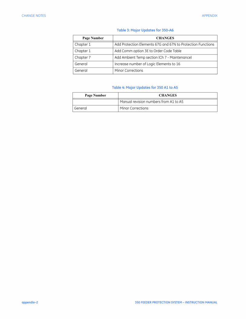
appendix–2 350 FEEDER PROTECTION SYSTEM – INSTRUCTION MANUAL
CHANGE NOTES APPENDIX
Chapter 1 Add Protection Elements 67G and 67N to Protection Functions
Chapter 1 Add Comm option 3E to Order Code Table
Chapter 7 Add Ambient Temp section (Ch 7 - Maintenance)
General Increase number of Logic Elements to 16
General Minor Corrections
Table 4: Major Updates for 350 A1 to A5
Page Number CHANGES
Manual revision numbers from A1 to A5
General Minor Corrections
Table 3: Major Updates for 350-A6
Page Number CHANGES