features the ductile iron society is awarded the … issue 3.pdf · the ductile iron society is...
TRANSCRIPT
The Ductile Iron News - Issue 3, 2002
file:///C|/WEBSHARE/062013/magazine/2002_3/index.htm[7/1/2013 9:23:24 AM]
To Promote the production and application of ductile iron castings Issue 3, 2002
The Ductile Iron Society is awarded the Society/Association of the Year
John Keough (left) and Jack Hall (center) accept the Foundry EducationalFoundation's award for "Society/Association of the Year", for the Ductile IronSociety. Presenting the award is Bill Sorensen, Executive Director of FEF. JackHall is the Executive Director of the Ductile Iron Society and John Keough ofApplied Process, Inc. is the DIS representative to FEF. .
FEATURES
•Cover Story - Ductile Iron Societyreceives the Society/Association ofthe Year Award - See Photos
• Surface Defects in Iron Castings
• Applications of ADI
• Opportunities in Metal Casting
• FEF College Industry Conference
• Spectrometer Standards
• AFS Trade Commission
DEPARTMENTS
• News Briefs
• Advertisers
• Back Issues
• DIS Home Page
View Ductile Iron Related Publications
Located in Strongsville, Ohio, USA15400 Pearl Road, Suite 234; Strongsville,Ohio 44136 Billing Address: 2802 Fisher Road, Columbus, Ohio 43204 Phone (440) 665-3686; Fax (440) 878-0070email:[email protected]
The Ductile Iron News - An Update on the Formation and Control of Lustrous Carbon Surface Defects in Iron Castings
file:///C|/WEBSHARE/062013/magazine/2002_3/surfacedefects.htm[7/1/2013 9:23:39 AM]
To Promote the production and application of ductile iron castings Issue 3, 2002
An Update on the Formation and Control of Lustrous Carbon Surface Defects
in Iron CastingsBack to Issue 3, 2002 Index page
by: R. L. Naro, ASI International, Ltd, Cleveland, Ohio 44114
ABSTRACT
This paper will update lustrous carbon research that was initiated by the author in the mid 1970's.This updated paper examines new phenolic urethane binder technology and compares lustrouscarbon defect susceptibility to older systems. The lustrous carbon forming tendencies of 2002phenolic urethane no-bake binders are compared to furan and ester cured phenolic no-bakebinders. Phenolic urethane cold box binder performance was also investigated. New methods fordefect elimination include the venting and vacuum exhausting of mold gases during pouring.
Current standard cold-box binder formulations provide virtually identical gray iron casting resultscompared to the earlier 1970 research. Cold-box binder systems formulated with new, lessvolatile solvent systems (biodiesel or vegetable oil-based solvents) showed significantly reducedtendencies for lustrous carbon formation. Current phenolic urethan no-bake binders aresomewhat less susceptible to lustrous carbon formation. Furan and ester cured phenolic no-bakebinders do not produce lustrous carbon defects. Venting and application of vacuum during metalpouring were both effective in minimizing lustrous carbon wrinkling. Lustrous carbon defectformation is more likely to occur when low pouring temperatures and lengthy pouring times areused. Defects are eliminated by increasing metal pouring temperatures, pouring faster andincorporating red-iron oxide additions to sand mixes. Red iron oxide additions eliminatedlustrous carbon while black iron oxide had very little effect.
INTRODUCTION
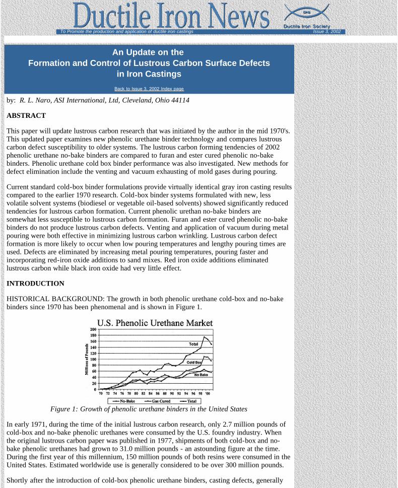
HISTORICAL BACKGROUND: The growth in both phenolic urethane cold-box and no-bakebinders since 1970 has been phenomenal and is shown in Figure 1.
Figure 1: Growth of phenolic urethane binders in the United States
In early 1971, during the time of the initial lustrous carbon research, only 2.7 million pounds ofcold-box and no-bake phenolic urethanes were consumed by the U.S. foundry industry. Whenthe original lustrous carbon paper was published in 1977, shipments of both cold-box and no-bake phenolic urethanes had grown to 31.0 million pounds - an astounding figure at the time.During the first year of this millennium, 150 million pounds of both resins were consumed in theUnited States. Estimated worldwide use is generally considered to be over 300 million pounds.
Shortly after the introduction of cold-box phenolic urethane binders, casting defects, generally

The Ductile Iron News - An Update on the Formation and Control of Lustrous Carbon Surface Defects in Iron Castings
file:///C|/WEBSHARE/062013/magazine/2002_3/surfacedefects.htm[7/1/2013 9:23:39 AM]
described as severely wrinkled surfaces defects, were reported by some of the early users of thesebinders. A few foundries also reported "leakers" in pressure-tight castings. The technicalliterature of the time contained little information regarding the specific conditions that increasedthe likelihood of these defects, soon to be known as "lustrous carbon", or methods to eliminatethese defects. The available information suggested that defect formation is affected by pouringtime and gating system design. Slow, turbulent filling and low pouring temperatures werereported to aggravate defect formation. (Clifford, M.J.).
Lustrous carbon surface imperfections were often referred to as "resin"; "kish" and "soot"defects, as the name "lustrous carbon" wasn't commonly used to describe these defects. Thedefects almost always occurred when using binders that evolved large quantities of carbonaceousdecomposition products during the filling of the mold by molten metal. Such carbonaceousresidues, however, can be beneficial when present in lesser amounts, as they provide a reducingatmosphere that minimizes oxidation at the mold-metal interface and generally improves castingsurface finish and peel. In steel castings, particularly those with thick sections, pock markingmay appear on casting surfaces. In high-alloy steels, such as stainless steel and nickel-basealloys, appreciable amounts of surface porosity and carbon pickup might occur; both areundesirable. Lustrous carbon defects have also become one of the major problems in lost foamcastings. (Moll, N.)
Lustrous carbon defects usually appear on castings as areas containing wrinkled, shiny surfaces,which often resemble cold shuts or seams. The appearance of these wrinkled or lapped areas hasoften been compared to that of elephant skin, alligator skin or crows feet. Usually the defectsoccur on external surfaces but can also form on cored surfaces of hydraulic cylinders, boilersections and pumps. In thin casting sections, lustrous carbon accumulations and entrapment canresult in hydraulic unsoundness as well as sub-surface "cold shut" defects. Thick metal sectionshave been reported to be less prone to lustrous carbon defects than thin sections. Under certainconditions, lustrous carbon defects may result in sub-surface blistering or surface laminations.Typical lustrous carbon defects found in a few gray iron industrial castings are illustrated inFigure 2.
a: Wrinkles on automotivebrake caliper b: Blister on disc brake rotor c: Surface lamination on disc
brake
d: Surface wrinkles on pulleyhub
e: Surface wrinkles in oil panwhich leaked
f: Surface wrinkling on lost foamtruck transmission part
Figure 2: Examples of typical lustrous carbon defects in industrial castings.
Microstructural examination of areas containing these defects often reveals discontinuitiesextending deep into the casting body. Figure 3 illustrates typical lustrous carbon surface pockmarking defects found in heavy section steel castings.
Lustrous carbon defects can occur with many binder systems. Thedefects can form with oil-alkyd-isocyanate no-bake binders, cold-box and no-bake phenolic urethane binder systems, certain gradesof furfuryl alcohol, urea-furfuryl alcohol (furan) no-bake binders

The Ductile Iron News - An Update on the Formation and Control of Lustrous Carbon Surface Defects in Iron Castings
file:///C|/WEBSHARE/062013/magazine/2002_3/surfacedefects.htm[7/1/2013 9:23:39 AM]
Figure 3: Surface pockmarking on steel casting
and phenolic shell-sand systems (Wragg, Greenhill, Clifford,Behring). Lustrous carbon related surface defects are not peculiarto the chemically curing binder systems; they also are commonlyfound on castings made in green sand molds containing largeamounts of seacoal (Kvasha, Bindernagel, Petrela, Beale, Draper).
BINDER DEVELOPMENTS 1977 to 2002 The phenolic urethane binder system consists of no-bake and gas cured resins. Part 1 is a phenolic resin (poly-benzylic-ether-phenolic resin) dilutedapproximately 50 percent with solvents. Part 2 is a polymeric di-isocyanate resin diluted withapproximately 25 percent solvents. The solvents can be composed of aliphatic, aromatic orvegetable oil-based derivatives (Biodiesel), or various blends thereof. One of the primarypurposes of the solvents is to reduce binder viscosity. Typically, the viscosities of the Part I andPart II resins are adjusted to 300 cps or lower to provide good pumping properties, rapid andefficient sand coating qualities and good flowability of mixed sand. Secondly, the solventsenhance resin reactivity and control bench life. An amine-based catalyst is used as the curingagent for the no-bake binder while a gaseous amine (triethylamine or dimethylethyl amine) isused for the gas-cured binder.
Although the general chemistry of phenolic urethane binders remains essentially the same as thesystem investigated in 1977, (Naro 1977) there have been numerous modifications in resinformulations involving both the phenolic base resin as well as the solvent system package. ThePart I phenolic base resin has been modified to reduce odor by reducing free formaldehydelevels. This is especially apparent when hot foundry sands are used. In addition, because ofefforts to reduce solvent evaporation, the solvent system has been modified to incorporate higherboiling point solvents or new solvents systems with improved environmental properties(Biodiesel). Because these solvents remain entrapped in the binder film, the newer formulatedbinder systems might, in fact, be more prone to lustrous carbon surface defects.
All current organic binder systems are based on the elements carbon, hydrogen, oxygen, and insome cases nitrogen. The chemical makeup of phenolic urethane cold-box and no-bake binders,compared to other popular binder systems is shown in Table 1 (Chang).
Table 1: Approximate chemical composition of cold-box and no-bake binders (Chang)
Binder Type % Carbon % Hydrogen % Nitrogen % OxygenPU Cold-box (1971) 72.0 8.5 3.9 15.5PU No-bake (1971) 72.0 8.5 3.9 15.5PU Cold-box (2002 standard) 73.0 7.9 3.9 14.8PU Cold-box (2002 biodiesel) 68.4 8.1 4.0 20.0
(Biodiesel or vegetable-oil based solvents)PU Cold-box (2002 all aromatic) 74.6 7.6 3.4 14.8
(All aromatic solvents)PU No-bake (2002 standard) 75.3 8.0 3.4 13.7Premium Furan No-bake (2002) 52.9 6.6 0.56 38.4Phenolic Ester No-bake 31.5 8.4 0.02 60.1
At ferrous casting temperatures, the presence of these elements and their subsequentdecomposition can produce a variety of casting defects. The following gaseous reactions arethermodynamically possible, and under the right conditions, might occur at the mold-metalinterface (Naro 1999):
Binder ----------- > H (nascent) -> H2 (g)Binder ----------- > N (nascent) ---> N2 (g)
Fe + H2O vapor (binder) --------> FeO + 2H (nascent)3 H2 (binder) + N2 (binder) > 2NH3(g) --------> 6H(nascent) + 2N(nascent)
FeO + C (binder) ---------> CO (g) + Fe
Although the first four reactions are likely to promote both surface and subsurface porositydefects, the last reaction usually results only in surface defects, such as surface pock marking or,more frequently, lustrous carbon laps and surface wrinkles (Naro 1977).
The Ductile Iron News - An Update on the Formation and Control of Lustrous Carbon Surface Defects in Iron Castings
file:///C|/WEBSHARE/062013/magazine/2002_3/surfacedefects.htm[7/1/2013 9:23:39 AM]
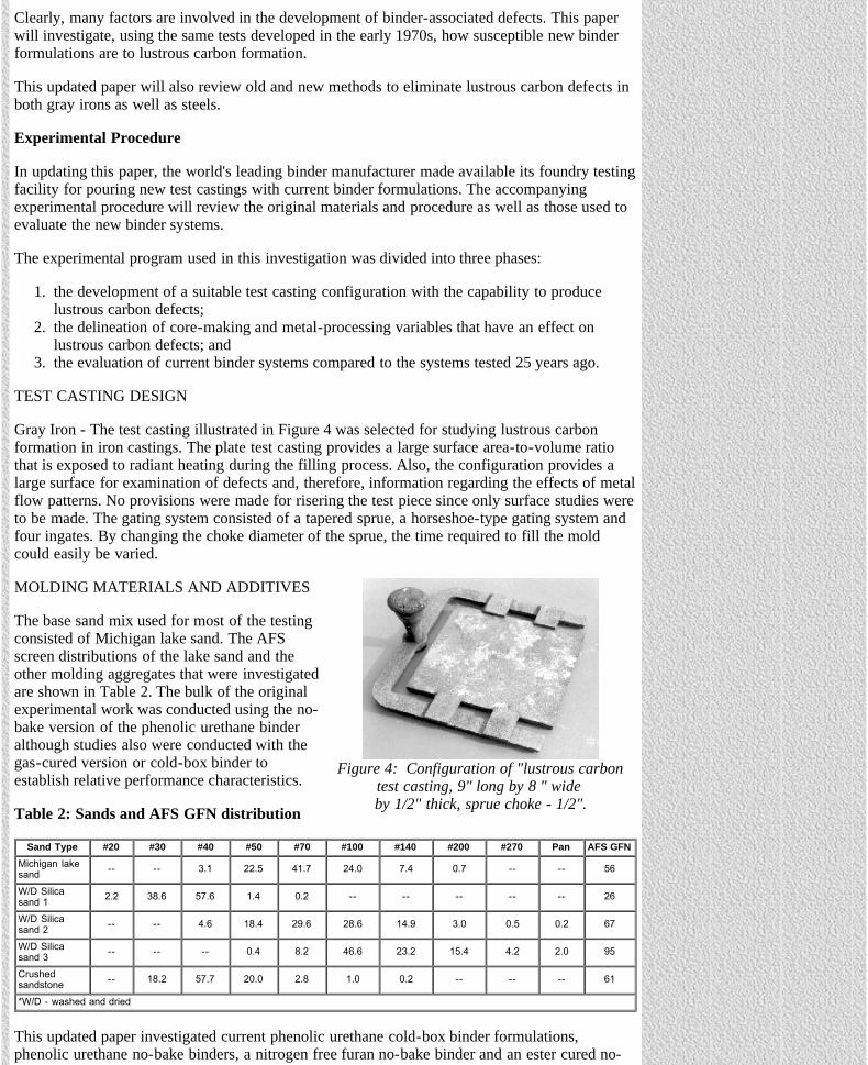
Figure 4: Configuration of "lustrous carbontest casting, 9" long by 8 " wide by 1/2" thick, sprue choke - 1/2".
Clearly, many factors are involved in the development of binder-associated defects. This paperwill investigate, using the same tests developed in the early 1970s, how susceptible new binderformulations are to lustrous carbon formation.
This updated paper will also review old and new methods to eliminate lustrous carbon defects inboth gray irons as well as steels.
Experimental Procedure
In updating this paper, the world's leading binder manufacturer made available its foundry testingfacility for pouring new test castings with current binder formulations. The accompanyingexperimental procedure will review the original materials and procedure as well as those used toevaluate the new binder systems.
The experimental program used in this investigation was divided into three phases:
1. the development of a suitable test casting configuration with the capability to producelustrous carbon defects;
2. the delineation of core-making and metal-processing variables that have an effect onlustrous carbon defects; and
3. the evaluation of current binder systems compared to the systems tested 25 years ago.
TEST CASTING DESIGN
Gray Iron - The test casting illustrated in Figure 4 was selected for studying lustrous carbonformation in iron castings. The plate test casting provides a large surface area-to-volume ratiothat is exposed to radiant heating during the filling process. Also, the configuration provides alarge surface for examination of defects and, therefore, information regarding the effects of metalflow patterns. No provisions were made for risering the test piece since only surface studies wereto be made. The gating system consisted of a tapered sprue, a horseshoe-type gating system andfour ingates. By changing the choke diameter of the sprue, the time required to fill the moldcould easily be varied.
MOLDING MATERIALS AND ADDITIVES
The base sand mix used for most of the testingconsisted of Michigan lake sand. The AFSscreen distributions of the lake sand and theother molding aggregates that were investigatedare shown in Table 2. The bulk of the originalexperimental work was conducted using the no-bake version of the phenolic urethane binderalthough studies also were conducted with thegas-cured version or cold-box binder toestablish relative performance characteristics.
Table 2: Sands and AFS GFN distribution
Sand Type #20 #30 #40 #50 #70 #100 #140 #200 #270 Pan AFS GFNMichigan lakesand -- -- 3.1 22.5 41.7 24.0 7.4 0.7 -- -- 56
W/D Silicasand 1 2.2 38.6 57.6 1.4 0.2 -- -- -- -- -- 26
W/D Silicasand 2 -- -- 4.6 18.4 29.6 28.6 14.9 3.0 0.5 0.2 67
W/D Silicasand 3 -- -- -- 0.4 8.2 46.6 23.2 15.4 4.2 2.0 95
Crushedsandstone -- 18.2 57.7 20.0 2.8 1.0 0.2 -- -- -- 61
*W/D - washed and dried
This updated paper investigated current phenolic urethane cold-box binder formulations,phenolic urethane no-bake binders, a nitrogen free furan no-bake binder and an ester cured no-

The Ductile Iron News - An Update on the Formation and Control of Lustrous Carbon Surface Defects in Iron Castings
file:///C|/WEBSHARE/062013/magazine/2002_3/surfacedefects.htm[7/1/2013 9:23:39 AM]
bake phenolic binder system. The various binder systems investigated are shown in Table 3.
Table 3: Binders evaluated for lustrous carbon susceptibility
Binder Percentage / Ratio (Pt 1 to Pt 2) CommentsCold-box A 1.5% BOS, 55.45 ratio 1971 formulation
Cold-box B 1.5% BOS, 55/45 ratio 2002 standard formulation, long bench-lifesolvents (5% biodiesel)
Cold-box C 1.5% BOS, 55/45 ratio 2002 formulation, long bench-life solvents (allbiodiesel), an environmentally friendly system
Cold-box D 1.5% BOS, 55/45 ratioExperimental system incorporating allaromatic, low boiling point, high evaporationrate solvents
PU No-bake A 1.5% BOS, 55/45 ratio 1971 formulation
PU No-bake B 1.5% BOS, 55/45 ratio2002 standard formulation, low odor, low freeformaldehyde, high solids content, minimalaromatic solvent content
Furan No-bake 1.5% BOS, 30% catalyst, BOB Premium, nitrogen free furan no-bake binderPhenolic-Ester No-bake 1.5% BOS, 30% co-reactant, BOB Ester cured phenolic no-bake binder
*BOS - Based on sand weight, BOB - Based on binder weight
All sand mixes were prepared in a small batch mixer by adding the phenolic resin component(Part 1) and catalyst to the sand and then mixing for 2 minutes. Next, the appropriate amount ofpolymeric isocyanate (Part 2) was added and mixed for an additional 2 minutes. The preparedmix was immediately hand-tucked into the test patterns. Strip times averaged 5 minutes. Cold-box mixes were cured with triethylamine. Molds were aged overnight before pouring. The furanno-bake and the ester cured phenolic no-bake binders were prepared in a similar manner;catalyst or co-reactant was first added to sand, mixed for 2 minutes, then the resin was added andmixed for an additional 2 minutes before being discharged into the test pattern.
The selection of suitable sand additives was determined after reviewing thermodynamic data(Elliot). Because a reducing atmosphere within the mold cavity appears to promote lustrouscarbon formation, sand additives were selected to minimize or change the mold atmosphere toone promoting oxidizing conditions. The materials selected included carbonates, nitrates, borates,sulfates and several metal oxides, each of which is capable of providing an oxidizing atmosphereunder equilibrium conditions at the pouring temperatures employed. All of the materials usedwere of technical grade or higher purity and in powder form, 200 mesh or finer.
PREPARATION OF TEST CASTINGS
Gray iron test castings were poured with a high carbon-equivalent, inoculated Class 30 iron.Melts were superheated to 2800°F (1538°C) in a 300 pound, basic-lined induction furnace andtapped into preheated, clay-graphite crucibles. Pouring temperatures were carefully monitoredthrough measurements in the ladle with an immersion pyrometer. All test castings were poured at2500°F (1371°C) except in those cases where the effect of varying metal temperature wasdetermined. The time needed to completely fill the test mold was recorded for each casting. Mostcastings were poured in 25 seconds except when pouring time effects were determined. Castingswere allowed to cool overnight and were shaken out the next day.
MACRO AND MICROSTRUCTURAL EXAMINATION
Each casting was carefully examined upon shakeout and the general conditions of the cope, dragand side surfaces, shakeout behavior and extent of lustrous carbon surface deposits and wrinklingextent were recorded. Selected test castings exhibiting typical lustrous carbon defects werephotographed at 1.5-power magnification. Other castings exhibiting severe defects weresectioned and metallographically examined. A surface defect rating system was developed toassess relative lustrous carbon forming tendencies. The following rating system was used toassess relative surface finish of the test castings:
1. Excellent, no evidence of lustrous carbon (LC) films at shakeout, dull finish 2. Good, nil amounts of LC films at shakeout, general dull finish3. Fair, some shiny deposits of LC films, some surface wrinkling4. Poor, shiny deposits of LC films adhering to casting surfaces, moderate surface wrinkling5. Very poor, heavy deposits LC films adhering to the casting at shakeout, severe wrinkling
The Ductile Iron News - An Update on the Formation and Control of Lustrous Carbon Surface Defects in Iron Castings
file:///C|/WEBSHARE/062013/magazine/2002_3/surfacedefects.htm[7/1/2013 9:23:39 AM]
Figure 6: Surface of test castingcontaining typical wrinkling defects
RESULTS AND DISCUSSION
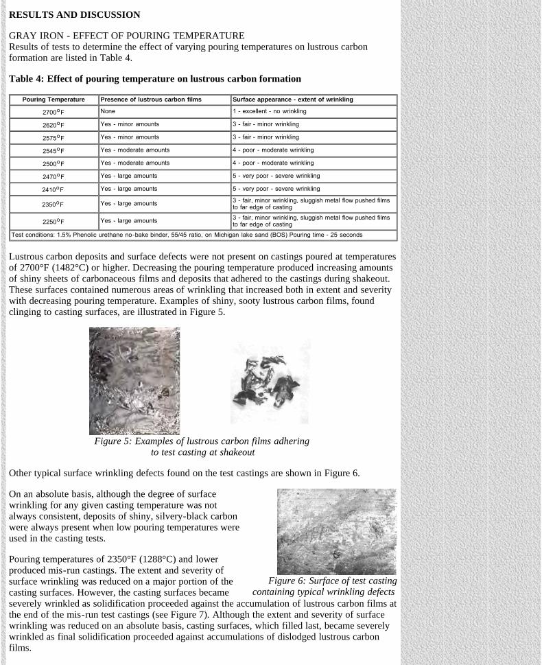
GRAY IRON - EFFECT OF POURING TEMPERATURE Results of tests to determine the effect of varying pouring temperatures on lustrous carbonformation are listed in Table 4.
Table 4: Effect of pouring temperature on lustrous carbon formation
Pouring Temperature Presence of lustrous carbon films Surface appearance - extent of wrinkling
2700oF None 1 - excellent - no wrinkling
2620oF Yes - minor amounts 3 - fair - minor wrinkling
2575oF Yes - minor amounts 3 - fair - minor wrinkling
2545oF Yes - moderate amounts 4 - poor - moderate wrinkling
2500oF Yes - moderate amounts 4 - poor - moderate wrinkling
2470oF Yes - large amounts 5 - very poor - severe wrinkling
2410oF Yes - large amounts 5 - very poor - severe wrinkling
2350oF Yes - large amounts 3 - fair, minor wrinkling, sluggish metal flow pushed filmsto far edge of casting
2250oF Yes - large amounts 3 - fair, minor wrinkling, sluggish metal flow pushed filmsto far edge of casting
Test conditions: 1.5% Phenolic urethane no-bake binder, 55/45 ratio, on Michigan lake sand (BOS) Pouring time - 25 seconds
Lustrous carbon deposits and surface defects were not present on castings poured at temperaturesof 2700°F (1482°C) or higher. Decreasing the pouring temperature produced increasing amountsof shiny sheets of carbonaceous films and deposits that adhered to the castings during shakeout.These surfaces contained numerous areas of wrinkling that increased both in extent and severitywith decreasing pouring temperature. Examples of shiny, sooty lustrous carbon films, foundclinging to casting surfaces, are illustrated in Figure 5.
Figure 5: Examples of lustrous carbon films adhering to test casting at shakeout
Other typical surface wrinkling defects found on the test castings are shown in Figure 6.
On an absolute basis, although the degree of surfacewrinkling for any given casting temperature was notalways consistent, deposits of shiny, silvery-black carbonwere always present when low pouring temperatures wereused in the casting tests.
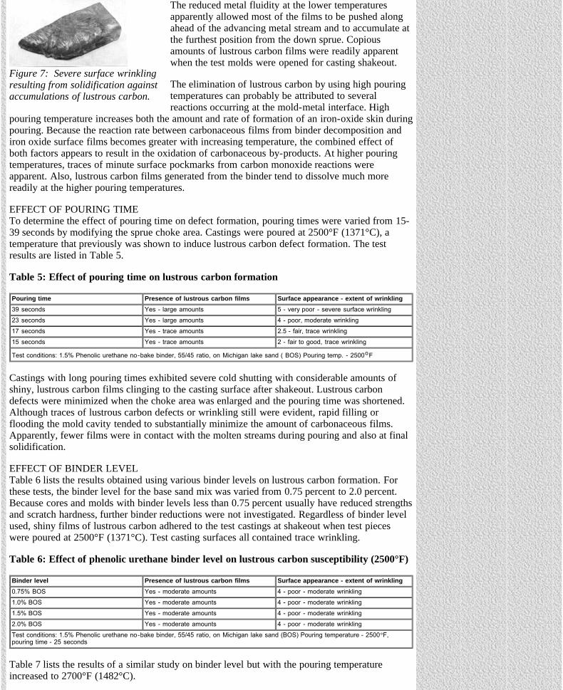
Pouring temperatures of 2350°F (1288°C) and lowerproduced mis-run castings. The extent and severity ofsurface wrinkling was reduced on a major portion of thecasting surfaces. However, the casting surfaces becameseverely wrinkled as solidification proceeded against the accumulation of lustrous carbon films atthe end of the mis-run test castings (see Figure 7). Although the extent and severity of surfacewrinkling was reduced on an absolute basis, casting surfaces, which filled last, became severelywrinkled as final solidification proceeded against accumulations of dislodged lustrous carbonfilms.
The Ductile Iron News - An Update on the Formation and Control of Lustrous Carbon Surface Defects in Iron Castings
file:///C|/WEBSHARE/062013/magazine/2002_3/surfacedefects.htm[7/1/2013 9:23:39 AM]
Figure 7: Severe surface wrinklingresulting from solidification againstaccumulations of lustrous carbon.
The reduced metal fluidity at the lower temperaturesapparently allowed most of the films to be pushed alongahead of the advancing metal stream and to accumulate atthe furthest position from the down sprue. Copiousamounts of lustrous carbon films were readily apparentwhen the test molds were opened for casting shakeout.
The elimination of lustrous carbon by using high pouringtemperatures can probably be attributed to severalreactions occurring at the mold-metal interface. High
pouring temperature increases both the amount and rate of formation of an iron-oxide skin duringpouring. Because the reaction rate between carbonaceous films from binder decomposition andiron oxide surface films becomes greater with increasing temperature, the combined effect ofboth factors appears to result in the oxidation of carbonaceous by-products. At higher pouringtemperatures, traces of minute surface pockmarks from carbon monoxide reactions wereapparent. Also, lustrous carbon films generated from the binder tend to dissolve much morereadily at the higher pouring temperatures.
EFFECT OF POURING TIME To determine the effect of pouring time on defect formation, pouring times were varied from 15-39 seconds by modifying the sprue choke area. Castings were poured at 2500°F (1371°C), atemperature that previously was shown to induce lustrous carbon defect formation. The testresults are listed in Table 5.
Table 5: Effect of pouring time on lustrous carbon formation
Pouring time Presence of lustrous carbon films Surface appearance - extent of wrinkling39 seconds Yes - large amounts 5 - very poor - severe surface wrinkling23 seconds Yes - large amounts 4 - poor, moderate wrinkling17 seconds Yes - trace amounts 2.5 - fair, trace wrinkling15 seconds Yes - trace amounts 2 - fair to good, trace wrinkling
Test conditions: 1.5% Phenolic urethane no-bake binder, 55/45 ratio, on Michigan lake sand ( BOS) Pouring temp. - 2500oF
Castings with long pouring times exhibited severe cold shutting with considerable amounts ofshiny, lustrous carbon films clinging to the casting surface after shakeout. Lustrous carbondefects were minimized when the choke area was enlarged and the pouring time was shortened.Although traces of lustrous carbon defects or wrinkling still were evident, rapid filling orflooding the mold cavity tended to substantially minimize the amount of carbonaceous films.Apparently, fewer films were in contact with the molten streams during pouring and also at finalsolidification.
EFFECT OF BINDER LEVELTable 6 lists the results obtained using various binder levels on lustrous carbon formation. Forthese tests, the binder level for the base sand mix was varied from 0.75 percent to 2.0 percent.Because cores and molds with binder levels less than 0.75 percent usually have reduced strengthsand scratch hardness, further binder reductions were not investigated. Regardless of binder levelused, shiny films of lustrous carbon adhered to the test castings at shakeout when test pieceswere poured at 2500°F (1371°C). Test casting surfaces all contained trace wrinkling.
Table 6: Effect of phenolic urethane binder level on lustrous carbon susceptibility (2500°F)
Binder level Presence of lustrous carbon films Surface appearance - extent of wrinkling0.75% BOS Yes - moderate amounts 4 - poor - moderate wrinkling1.0% BOS Yes - moderate amounts 4 - poor - moderate wrinkling1.5% BOS Yes - moderate amounts 4 - poor - moderate wrinkling2.0% BOS Yes - moderate amounts 4 - poor - moderate wrinklingTest conditions: 1.5% Phenolic urethane no-bake binder, 55/45 ratio, on Michigan lake sand (BOS) Pouring temperature - 2500°F,pouring time - 25 seconds
Table 7 lists the results of a similar study on binder level but with the pouring temperatureincreased to 2700°F (1482°C).
The Ductile Iron News - An Update on the Formation and Control of Lustrous Carbon Surface Defects in Iron Castings
file:///C|/WEBSHARE/062013/magazine/2002_3/surfacedefects.htm[7/1/2013 9:23:39 AM]
Table 7: Effect of phenolic urethane binder level on lustrous carbon susceptibility (2700°F)
Binder level Presence of lustrous carbon films Surface appearance - extent of wrinkling0.75% BOS None present 1.5 - Good, no wrinkling1.0% BOS None present 1.5 - Good, no wrinkling1.5% BOS None present 1.5 - Good, no wrinkling2.0% BOS None present 1.5 - Good, no wrinklingTest conditions: 1.5% Phenolic urethane no-bake binder, 55/45 ratio, on Michigan lake sand (BOS) Pouring temperature - 2700OF,pouring time - 25 seconds
Test casting appearance at shakeout was excellent and carbonaceous films were absent, as werewrinkle defects on the casting surfaces. Test castings made using extreme binder levels of 3.0percent were also defect free. This further illustrates the importance of employing high pouringtemperatures for lustrous carbon elimination. If pouring temperatures of 2700°F (1482°C) orhigher cannot be used because of equipment limitations or casting specifications, other methodsto reduce the amount or rate of binder decomposition must be employed to eliminate lustrouscarbon. In evaluating the lustrous carbon tendencies of phenolic urethane cold-box binders, usingthe same conditions shown in Tables 6 and 7, casting performance was almost identical to thephenolic urethane no-bake binders.
EFFECT OF PHENOLIC URETHANE BINDER RATIO Since the Part 1 phenolic resin has a slightly higher carbon content than does the Part 2polymeric isocyanate, the ratio of Part 1 to Part 2 was varied to investigate the effect of binderratio on lustrous carbon formation. Molds with Part 1 to Part 2 ratios of 70/30, 60/40, 50/50,40/60 and 30/70 were prepared at 1.5 percent total binder and were poured at 2500°F (1371°C).
Molds prepared with ratios of 70/30, 60/40, and 50/50 had high tensile strengths and high scratchhardness. Ratios of 40/60 and 30/70 produced lower strength molds. Lustrous carbon films wereobserved adhering to the casting surfaces at shakeout regardless of the binder ratio used. Castingsproduced with binder ratios of 70/30, 60/40, and 50/50 provided similar performance with sometraces of surface wrinkling. Minor levels of lustrous carbon wrinkling occurred at 40/60 ratiosalong with some surface burn-in. Binder ratios of 30/70 produced very poor casting surfacefinish and extensive lustrous carbon wrinkling defects formed on drag surfaces. Unbalancedratios favoring excess Part 2 contain un-reacted polymeric isocyanate. This condition appears toincrease the amount of lustrous carbon surface wrinkling propensity. Binder ratios favoringexcess polymeric isocyanate levels also had higher total carbon concentrations for the samesolvent system. The reduced solvent or higher solids content of Part 2 resins was responsible forthe increased levels of lustrous carbon.
EFFECT OF SAND TYPE ON LUSTROUS CARBON FORMATIONTable 8 lists the effect of sand type on lustrous carbon defect formation.
Table 8: Effect of sand type on lustrous carbon formation
Sand type Presence of lustrous carbon films Surface appearance - extent of wrinklingMichigan Lake Yes - moderate amounts 4 - poor - moderate wrinklingW/D Silica 1 Yes - minor amounts 4 - poor - trace wrinklingW/D Silica 2 Yes - minor amounts 3 - fair - trace wrinklingW/D Silica 3 Yes - minor amounts 3 - fair - trace wrinklingCrushed sandstone Yes - moderate amounts 4 - poor - moderate wrinklingTest conditions: 1.5% Phenolic urethane no-bake binder, 55/45 ratio, on Michigan lake sand (BOS) Pouring temperature - 2500OF,pouring time - 25 seconds
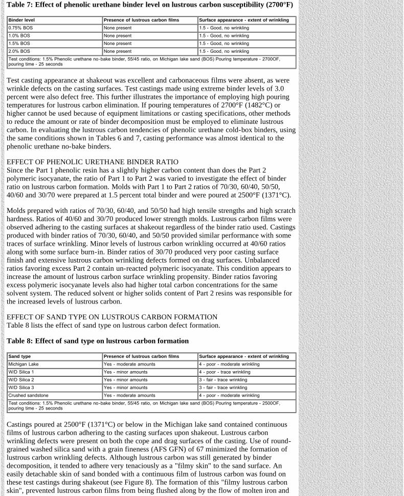
Castings poured at 2500°F (1371°C) or below in the Michigan lake sand contained continuousfilms of lustrous carbon adhering to the casting surfaces upon shakeout. Lustrous carbonwrinkling defects were present on both the cope and drag surfaces of the casting. Use of round-grained washed silica sand with a grain fineness (AFS GFN) of 67 minimized the formation oflustrous carbon wrinkling defects. Although lustrous carbon was still generated by binderdecomposition, it tended to adhere very tenaciously as a "filmy skin" to the sand surface. Aneasily detachable skin of sand bonded with a continuous film of lustrous carbon was found onthese test castings during shakeout (see Figure 8). The formation of this "filmy lustrous carbonskin", prevented lustrous carbon films from being flushed along by the flow of molten iron and
The Ductile Iron News - An Update on the Formation and Control of Lustrous Carbon Surface Defects in Iron Castings
file:///C|/WEBSHARE/062013/magazine/2002_3/surfacedefects.htm[7/1/2013 9:23:39 AM]
inhibited the formation of wrinkling defects in the solidifying metal surface.
Figure 8: Layer of lustrous carbon bonded sand (left) and castsurface from which bonded layer was removed (right)
The effect of grain size was investigated using washed silica sands of different AFS grainfineness numbers. A fine silica sand (AFS GFN 95) produced results similar to the AFS GFN 67silica sand. The lustrous carbon films that formed adhered to the sand, and minimal wrinklingdefects were observed on the casting. The coarser silica sand (AFS GFN 26) exhibited extensivesurface penetration. Lustrous carbon sheets also were present in the penetrated layer, but again,few wrinkling defects were observed. A coarse crushed sandstone-type sand (AFS GFN 42)produced results similar to those of the Michigan lake sand.
These results indicate that sand grain size has little effect on the formation of lustrous carbondefects, however, sand grain geometry seems to have an effect on reducing lustrous carbonwrinkling. Lustrous carbon films seemed to preferentially form a continuous and tightly bondedfilm with round grained sands; the lustrous carbon films remained at the mold-metal interfaceand were not dislodged by molten metal flow.
EFFECT OF 2002 BINDER FORMULATIONSPhenolic Urethane Cold-box Binders - Although the base phenolic resin used in cold-box bindershas remained essentially the same since the mid-1970's, significant changes and modificationshave been made in the area of solvents. Solvent modifications have been incorporated into cold-box binders to increase bench-life of mixed sand, to reduce odor, to improve cured sandproperties, and more recently, to provide binder systems that are more environmentally friendlyand eliminate or minimize evaporation. Using those conditions that promoted lustrous carbonformation, numerous tests were run to compare lustrous carbon forming tendencies of newsystems compared to mid-1970 cold-box binder formulations. The older cold-box binders wereformulated using original recipes and solvents from the 1970's.
Table 9 lists the results of casting tests comparing old versus new resin formulations.
Table 9: Effect of cold-box binder solvent formulation on lustrous carbon susceptibility
Binder system (solvent package) Presence of lustrous carbon films Surface appearance - extent of wrinklingPU CB (1971 formulation) Yes - moderate deposits 4 - poor - moderate wrinklingPU CB (2002 std. formulation) Yes - heavy deposits 5 - very poor, minor wrinklingPU CB (2002 all Biodiesel) None (dull surface) 2.0 - fair to good, no wrinklingPU CB (2002 all aromatic) Yes - trace amounts 3.5 - fair to poor, minor wrinkling
Test conditions: 1.5% Phenolic urethane cold-box binder on Michigan lake sand (BOS) Pouring temperature - 2500oF, pouring time - 25seconds
The year 2002 phenolic urethane cold-box binder provided slightly worse lustrous carbongenerating susceptibility compared with early 1970 versions of the binder. Somewhat greaterquantities of lustrous carbon films adhered to the casting at shakeout. Surface wrinkling wasidentical. Cold-box binders formulated with all biodiesel solvents showed superior castingperformance. It was interesting to note that the all biodiesel solvent based cold-box binder had adull surface, and lustrous carbon films were totally absent. Cold-box resins based on biodieselsolvents contained only 68 percent carbon compared with 72 percent carbon for the 1970sformulation and 73 percent for the standard 2002 system. The oxygen level of the biodiesel-

The Ductile Iron News - An Update on the Formation and Control of Lustrous Carbon Surface Defects in Iron Castings
file:///C|/WEBSHARE/062013/magazine/2002_3/surfacedefects.htm[7/1/2013 9:23:39 AM]
based resin was almost 5 percent higher than standard cold-box formulations. This combinationof reduced carbon level and increased oxygen content was obviously responsible for theelimination of lustrous carbon.
Incorporating all aromatic solvents into a phenolic urethane cold-box binder tended to minimize,but not eliminate, lustrous carbon film formation. Although aromatic solvents are high in carbon,these low boiling point solvents evaporate prior to casting and provided reduced levels oflustrous carbon. During prolonged core storage, it is anticipated that a significant portion of thelow boiling point solvents will evaporate resulting in reduced lustrous carbon tendency. Duringcasting, low boiling point solvents will "flash off" rapidly compared to high boiling pointsolvents, which have a greater tendency to condense and form lustrous carbon at the mold metalinterface.
Although the 1977 lustrous carbon research downplayed the effect of solvents on lustrous carbonformation, clearly solvents do effect lustrous carbon formation. The newly reformulated biodieselsolvents, with reduced carbon and increased oxygen levels, provide vastly improved resistance tolustrous carbon defects.
No-bake Binders - The lustrous carbon susceptibilities of year 2002 phenolic urethane no-bakebinders compared with early 1970 versions of the binder are shown in Table 10. Also shown inTable 10 are the casting performance of a premium grade furan no-bake binder and an estercured phenolic no-bake binder.
Table 10: Effect of no-bake binder type and formulation on lustrous carbon susceptibility
Binder system (solvent package) Presence of lustrous carbon films Surface appearance - extent of wrinklingPU NB A (1971 formulation) Yes - heavy deposits 4 - poor - moderate wrinklingPU NB B (2002 std. formulation) Yes - moderate deposits 3 - fair, minor wrinklingFuran no-bake binder None 1.5 - very good, no surface wrinklingPhenolic Ester no-bake None 1.0 - excellent, no wrinklingTest conditions: 1.5% Phenolic urethane no-bake binder on Michigan lake sand (BOS) 1.5% Phenolic ester (BOS), 1.5% Furan, 30%catalyst Pouring temperature - 2500OF, pouring time - 25 seconds
The year 2002 version of the phenolic urethane no-bake binder provided improved castingperformance and reduced levels of lustrous carbon formation compared with the binderformulated with 1970s solvents and base resins. In fact, the incoming metal flow patterns couldeasily be detected on test-casting surfaces, which contained heavy, shiny lustrous carbondeposits. Neither the premium furan no-bake binder nor the phenolic ester cured no-bake bindershowed any evidence of lustrous carbon formation. Although both as-cast surfaces after shakeoutwere dull, the phenolic ester no-bake produced the best as-cast surface of all the binders tested.
ELIMINATION OF LUSTROUS CARBON DEFECTS
Effect of Sand Additives - Numerous compounds were evaluated as additives to change thereducing atmosphere in the mold cavity to an oxidizing atmosphere at low pouring temperatures.Materials were selected after careful study of thermodynamic data. They included metal oxides,sulfates, borates, carbonates and nitrates.
Table 11 summarizes results obtained with the better performing sand additions.
Table 11: Effect of sand additives on lustrous carbon formation
% Additive Presence of lustrous Carbonfilms
Surface appearance - extent ofWrinkling Comments
2% Fe3O4 (black) None 5 - traces of surface wrinkling Severe surface deterioration
2% Fe2O3 (red) None 1.5 - good, no wrinkling Minor surface finish deterioration
2% Fe2O3·nH2O(yellow ochre) None 1.5 - good , no wrinkling Minor surface finish deterioration
1% Al2(SO4)3 None 2 - traces of surface wrinkling Dull, oxidized surface
1% MnO2 Yes - heavy deposits 5 - severe surface wrinkling Minor surface finish deterioration
Test conditions: 1.5% Phenolic urethane no-bake binder, 55/45 ratio, on Michigan lake sand (BOS) Pouring temperature - 2500oF,pouring time - 25 seconds

The Ductile Iron News - An Update on the Formation and Control of Lustrous Carbon Surface Defects in Iron Castings
file:///C|/WEBSHARE/062013/magazine/2002_3/surfacedefects.htm[7/1/2013 9:23:39 AM]
Hematite (red iron oxide Fe203) and yellow ochre were the only additives that completelyeliminated lustrous carbon film formation and surface wrinkling. However, a 2.0 percent additionlevel was required for complete elimination of lustrous carbon films and surface defects.Magnetite, which contains only a few weight percent less oxygen than hematite, was almosttotally ineffective in eliminating lustrous carbon when used in either powdered (200 mesh) orcoarser forms.
The above results clearly show the effects of iron-oxide mineralogy and chemistry. Althoughboth iron oxides had similar mesh sizes (325 mesh x down), the red-iron oxide (hematite) clearlyoutperformed the black-iron oxide (magnetite). Although black-iron oxide additions are incommon use today, much of the acceptance of black oxides is more likely related to surface areaconsiderations. Sand additives having low surface area allow for less resin consumption andimproved core-making economics. However, careful consideration must be given to the superiorcasting effectiveness of red-oxide in preventing lustrous carbon, compared to its less desirablecore making properties, when choosing an oxide addition.
All of the metal oxides tested produced varying degrees of deterioration in the casting surface.Although effective in oxidizing lustrous carbon, the enhanced oxidizing conditions created bythese additives appears to promote fayalite or burn-on reactions at the mold-metal interface.
Although additions of iron or sodium sulfates reduced the severity of lustrous carbon formation,use of aluminum sulfate was more effective. Other compounds were ineffective in reducinglustrous carbon formation or produced localized fluxing and severe surface deterioration.
Incorporation of oxidizing additions to sand mixes is not without disadvantages. Table 12summarizes the effects of additives on tensile strength properties of sand mixes.
Table 12: Effect of oxidizing additives on core tensile strength
% Additive 24 hour tensile strengthNone 350 psi
1.0% Fe2O3 (red) 302 psi
1.5% Fe2O3 (red) 278 psi
2.0% Fe2O3 (red) 252 psi
2.0% Fe2O3·nH2O 162 psi
1.0% Al2(SO4)3 268 psi
W/D silica sand with 1.5% phenolic urethane no-bake binder
Additions of red iron oxide up to 15% resulted in only a minor decrease in tensile strength butthe larger additions of 2.0% produced a moderate 70 pounds to 80 pounds per square inch (psi)decrease in strength. Yellow ochre performed similarly. Aluminum sulfate additions at the 1percent level produced little or no change in tensile properties. Larger additions were notinvestigated because of their adverse effect of strength reductions at a given binder level.
Effect of Venting - To study the effect of extracting carbon-rich gases from the mold cavityduring pouring operations, a series of test castings were poured in which both venting andapplication of a positive vacuum were applied to test molds.The results of the venting studies are shown in Table 13.
Table 13: Effect of venting and exhausting on lustrous carbon formation
Presence of lustrous carbon films Surface appearance - extent of Wrinkling
Standard - no venting Yes - heavy deposits 4 - poor - moderate wrinkling30 - 0.35 in. diameter vents Yes - moderate deposits 4 - poor, minor wrinklingVacuum assisted venting Yes - moderate deposits 2.5 - fair to good, no surface wrinklingVacuum supplied from "shop vacuum" pulling through 1.1 inch diameter vent (1.3 square inches)Test conditions: 1.5% Phenolic urethane no-bake binder, 55/45 ratio, on Michigan lake sand (BOS) 2002 binder versions, pouringtemperature - 2500OF, pouring time - 25 seconds
In non-vented molds, relatively heavy deposits of lustrous carbon adhered to the test casting at

The Ductile Iron News - An Update on the Formation and Control of Lustrous Carbon Surface Defects in Iron Castings
file:///C|/WEBSHARE/062013/magazine/2002_3/surfacedefects.htm[7/1/2013 9:23:39 AM]
shakeout. General surface finish also was very poor, though only minor surface wrinkling wasobserved. Venting of test molds by drilling 30 vents, each with a diameter of 0.35 inches,reduced the amount of lustrous carbon deposits on test castings. General surface finish improvedonly marginally, and minor evidence of surface wrinkling was still apparent. Using a vacuum toassist in removing carbon laden decomposition products from the mold cavity improved thesurface finish somewhat, though test castings still showed a very shiny, silvery surface withmoderate deposits of lustrous carbon.
Effect of Mold Coatings - The use of mold coatings was investigated to determine their effect onthe formation of lustrous carbon defects. Two coats of an alumina wash were applied to thesprue, gating, and plate surfaces of test molds. The wash was air-dried for 24 hours. Lustrouscarbon films adhered to the casting upon shakeout, and several wrinkling defects were found onthe cope surface.
A number of coatings were formulated to promote oxidizing conditions at the mold-metalinterface in an attempt to minimize lustrous carbon formation. Table 14 summarizes the resultsobtained with oxidizing coatings.
Table 14: Effect of oxidizing mold coatings on lustrous carbon formation
Mold coating Presence of lustrous carbonfilms
Surface appearance - extent ofWrinkling Comments
Alumina (2 coats) Moderate amounts adhering tocasting
3 - fair, traces of surfacewrinkling
Moderate amounts adhering tocasting
Manganese Dioxide (2 coats) Moderate amounts adhering tocasting
3.5 - fair, traces of surfacewrinkling
Severe surface finishdeterioration
Zinc Oxide (2 coats) Moderate amounts adhering tocasting
3.5 - fair, traces of surfacewrinkling
Moderate surface finishdeterioration
Yellow Ochre (2 coats) Trace amounts adhering tocasting 3 - traces of surface wrinkling Moderate amounts adhering to
castingTest conditions: 1.5% Phenolic urethane no-bake binder, 55/45 ratio, on Michigan lake sand (BOS) Pouring temperature - 2500OF,pouring time - 25 seconds
Manganese dioxide, zinc oxide and yellow ochre coatings did not eliminate lustrous carbondefects and resulted in deterioration of the casting surface finish. Burn-on was particularly heavywith the manganese dioxide wash. Apparently, hydrocarbon gases and residues generated frombinder decomposition during pouring diffuse through the permeable coating, still allowinglustrous carbon defects to occur.
Effect of Mold / Core Baking - Test molds were baked to determine whether volatile bindercomponents (solvents) influence the severity of lustrous carbon. Table 15 lists the results ofbaking tests on casting performance and binder weight losses.
Table 15: Effect of baking temperatures on lustrous carbon formation
Baking temperature Mold appearanceSurface appearance -
extent of surfacewrinkling
% Binder loss % Reduction in tensilestrength
425oF Little to no color change 2 - traces of surfacewrinkling 25% 25%
500oFDeep chocolate brown
color1.5 - no traces of lustrous
carbon 55% 40%
Test conditions: 1.5% Phenolic urethane no-bake binder on Michigan lake sand (BOS) Pouring temperature - 2500oF, pouring time - 25seconds Baking time - 2 hours
Test castings poured in molds baked at 425°F (218°C) for two hours exhibited some lustrouscarbon defects, and no improvement was noted in comparison with non-baked molds. Testcastings made in molds baked at 500°F (260°C) for two hours had excellent shakeoutappearance, and the casting surfaces were free from lustrous carbon films and associatedwrinkling defects.
Any of several chemical changes could occur in the binder by baking at 500°F (260°C). Theseinclude partial oxidation and elimination of constituents volatile at 500°F (260°C) orrearrangement of the cross-linked polymer. Any of these changes could be responsible forelimination of lustrous carbon from castings. It was noted that 500°F (260°C) baking changed the

The Ductile Iron News - An Update on the Formation and Control of Lustrous Carbon Surface Defects in Iron Castings
file:///C|/WEBSHARE/062013/magazine/2002_3/surfacedefects.htm[7/1/2013 9:23:39 AM]
color of test molds to chocolate brown while baking at 425°F (218°C) produced little colorchange. Test cores baked at 425°F (218°C) for two hours exhibited weight losses correspondingto 25 percent of the total binder content. Given that as much as 10 percent of the binder weightcan be volatilized during mixing from solvent loss, it is safe to assume that baking at 425°Feliminated all solvents. At the higher baking temperature of 500°F (260°C), weight lossescorresponding to 55 percent of the original binder weight were obtained, indicating binderoxidation plays a significant role in lustrous carbon elimination. The extent and degree of binderoxidation during pouring plays an important part in lustrous carbon elimination, as evidenced bythe casting performance of binders having reduced carbon and increased oxygen levels.
Although post-baking at 500°F (260°C) was effective for lustrous carbon control, core or mold-strength degradation might limit the usefulness of this method. As Table 15 shows, baking at500°F reduces the strength of cores by about 40%.
DISCUSSION
MECHANISM OF LUSTROUS CARBON FORMATION
Laps and Wrinkles - Iron Castings - Based on the physical appearance of lustrous carbon defectsin castings and the effects of variables previously described, a reasonable description of themechanism by which defects form can be proposed. As molten metal enters the mold cavity,thermal degradation of the binder produces hydrocarbon gases. The hydrocarbon rich vaporsubsequently re-condenses as pyrolytic graphitic deposits in films or sheets on the mold-cavitysurface. Figure 11 illustrates recovered deposits of lustrous carbon formed on test-mold surfacesduring pouring.
Figure 11: SEM Photographs showing a continuous carbon layerattached to the mold surface after metal pouring
As additional metal flows into the mold, these films may be flushed along ahead of the leadingedge of the incoming metal stream, as illustrated in the schematic of Figure 12.
Figure 12: Metal flow pattern in test casting
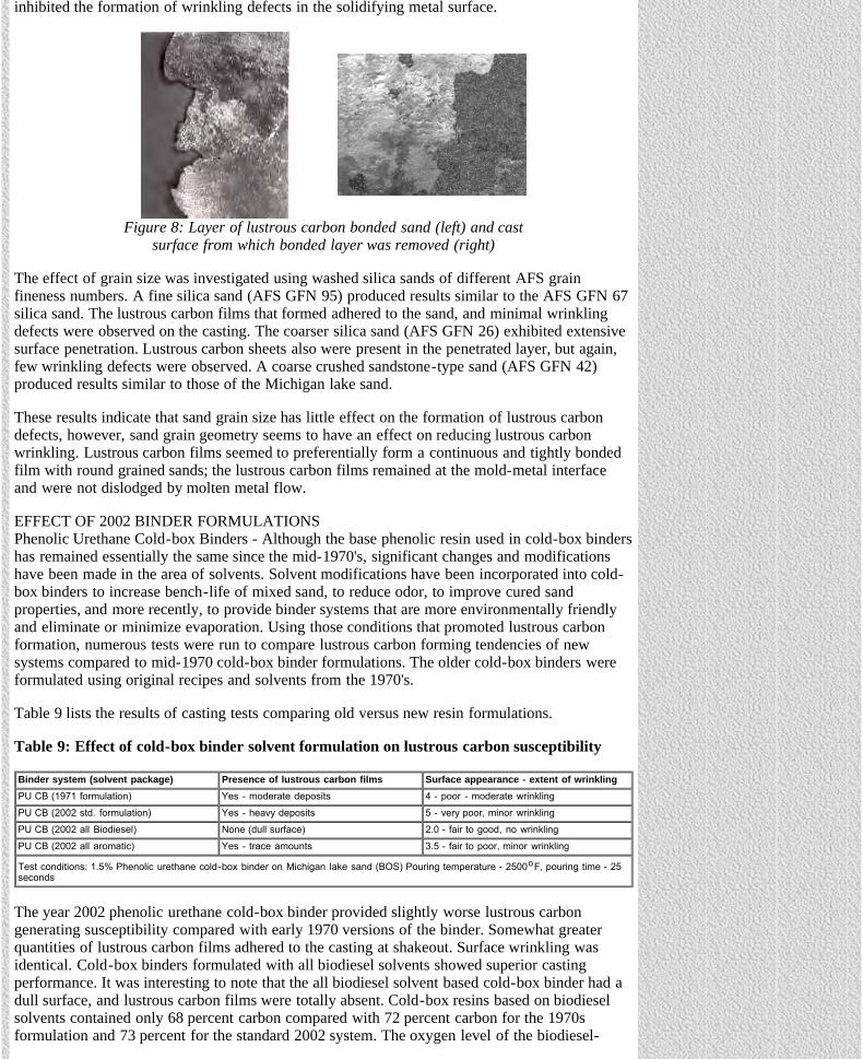
These films can roll up to substantial thickness. If not dissolved in the metal or oxidized,solidification can proceed against the accumulation of carbon films. This gives rise to thecharacteristic surface wrinkling associated with lustrous carbon defects. Figures 13a and 13billustrate test castings containing severe surface wrinkling. Examination of these casting surfacesindicates a strong tendency for defects to form along the edges of the first stream of molten metalthat enters the mold cavity. Defects also tended to form in the ingate areas, as well as the sidesand cope surfaces.
The Ductile Iron News - An Update on the Formation and Control of Lustrous Carbon Surface Defects in Iron Castings
file:///C|/WEBSHARE/062013/magazine/2002_3/surfacedefects.htm[7/1/2013 9:23:39 AM]
Figure 14: Microstructure of casting containingsevere lustrous carbon "leaker" in gray iron
a. b.Figure 13: Examples of severe surface wrinkling from lustrous
carbon formation in test castings
Under more severe pouring conditions, such as when using gating systems which produceturbulent flow and can cause cold shuts, lustrous carbon films can be flushed into the body of thecasting or become sandwiched between two merging streams of molten metal. In severe cases, alaminating effect can occur that also might result in surface blistering.
If the molten iron does not dissolve these films,they will prevent the welding of the mergingstreams of solidifying metal. A classic exampleof such a defect is illustrated in Figure 14 whichshows a discontinuity extending almost 0.25inch into the body of a gray iron casting.
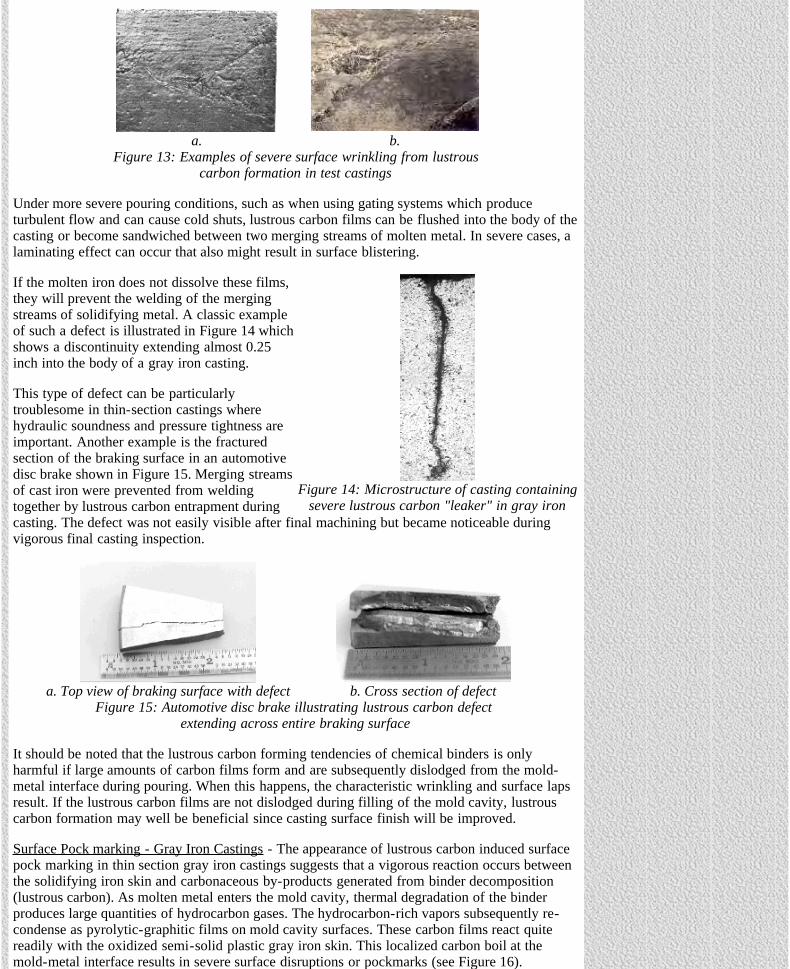
This type of defect can be particularlytroublesome in thin-section castings wherehydraulic soundness and pressure tightness areimportant. Another example is the fracturedsection of the braking surface in an automotivedisc brake shown in Figure 15. Merging streamsof cast iron were prevented from weldingtogether by lustrous carbon entrapment duringcasting. The defect was not easily visible after final machining but became noticeable duringvigorous final casting inspection.
a. Top view of braking surface with defect b. Cross section of defectFigure 15: Automotive disc brake illustrating lustrous carbon defect
extending across entire braking surface
It should be noted that the lustrous carbon forming tendencies of chemical binders is onlyharmful if large amounts of carbon films form and are subsequently dislodged from the mold-metal interface during pouring. When this happens, the characteristic wrinkling and surface lapsresult. If the lustrous carbon films are not dislodged during filling of the mold cavity, lustrouscarbon formation may well be beneficial since casting surface finish will be improved.
Surface Pock marking - Gray Iron Castings - The appearance of lustrous carbon induced surfacepock marking in thin section gray iron castings suggests that a vigorous reaction occurs betweenthe solidifying iron skin and carbonaceous by-products generated from binder decomposition(lustrous carbon). As molten metal enters the mold cavity, thermal degradation of the binderproduces large quantities of hydrocarbon gases. The hydrocarbon-rich vapors subsequently re-condense as pyrolytic-graphitic films on mold cavity surfaces. These carbon films react quitereadily with the oxidized semi-solid plastic gray iron skin. This localized carbon boil at themold-metal interface results in severe surface disruptions or pockmarks (see Figure 16).

The Ductile Iron News - An Update on the Formation and Control of Lustrous Carbon Surface Defects in Iron Castings
file:///C|/WEBSHARE/062013/magazine/2002_3/surfacedefects.htm[7/1/2013 9:23:39 AM]
Figure 16: Proposed mechanism of pock making or surfaceporosity resulting from lustrous carbon reactions in gray iron
Additions of relatively pure, red-iron oxide (Fe2O3) to PUN binders are effective in eliminatinglustrous carbon film formation and defects. Black-iron oxide (magnetite or Fe3O4) additions arenot as effective in eliminating surface pock marking. Other investigators have also shown thatadditions of Fe3O4 are not nearly as effective as hematite in controlled casting tests (Monroe,R.W., AFS Cured Sand Committee, Modern Castings 1982). Red-iron oxide apparently promotesthe oxidation of lustrous carbon films generated from binder decomposition and / or retards thedecomposition rate of the binder film on sand-grain surfaces (Hill, P.A.). Another reason whyred-iron oxide is so effective in eliminating lustrous carbon is that it contains 2.43 percent moreoxygen, 30.48 percent oxygen compared to 27.95 percent oxygen for magnetite.
In evaluating various grades of iron oxides, it should be noted that because commercial foundrygrades of red-iron oxide are naturally occurring minerals, some deposits might not work as wellas the grades used in these experiments.
RECOMMENDATIONS FOR LUSTROUS CARBON ELIMINATION:
The experimental results and the proposed mechanism of lustrous carbon formation suggestseveral techniques that can be employed to minimize or eliminate defects in casting operations.The best method for eliminating lustrous carbon is the employment of proper gating techniques.Accordingly, the following undesirable features should be eliminated from gating design: 1)employment of long, thin gates that enhance large metal temperature losses and 2) designs thatmaximize pouring time and/or turbulence.
In foundry operations where gating already is optimized or cannot be altered due to otherlimitations, other techniques may need to be used. If possible, pouring temperatures should beincreased to at least 2700°F (1482oC) unless metallurgical considerations, such as increasedtendency for chill, structure limitations or casting soundness, prohibit use of high pouringtemperatures (Naro, 1999). Secondly, the employment of suitable oxidizing additions to the sandmix, such as a minimum of 2.0 percent Fe203 (red-iron oxide or hematite) should eliminate orgreatly minimize lustrous carbon problems. In castings where lustrous carbon is still notcontrolled with oxidizing additions, larger quantities of 3.0 percent to 4.0 percent should beinvestigated. As a last resort, molds and cores could be baked at 500°F (260oC) for at least onehour (or until the molds or cores change to a deep brown color) to drive off the volatilecomponents of the binder that promote lustrous carbon formation.
With recent foundry concerns about the environment, foundries can use new phenolic urethanebinders formulated with environmentally friendly biodiesel (vegetable-based oil) solvents toreduce lustrous carbon. Further, phenolic urethane binders that are formulated with solvents thatdecrease carbon and increase oxygen levels provide vastly reduced lustrous carbon levels.
CONCLUSIONS
1) High metal casting temperatures were found to eliminate the formation of lustrous carbondefects. The amount of lustrous carbon increased as the pouring temperature decreased. Pouring

The Ductile Iron News - An Update on the Formation and Control of Lustrous Carbon Surface Defects in Iron Castings
file:///C|/WEBSHARE/062013/magazine/2002_3/surfacedefects.htm[7/1/2013 9:23:39 AM]
temperatures of 2700°F (1482oC) completely eliminated lustrous carbon in the experimentalplate casting.
2) Rapid filling of the test mold cavity decreased both the severity and amount of lustrous carbonformed.
3) Binder levels and sand type had only modest effect on lustrous carbon formation, thoughwashed silica sand minimized defects, presumably by restraining lustrous carbon films frombeing flushed away by flowing metal.
4) Offset binder ratios favoring minimal isocyanate levels (70/30, 60/40 and 50/50) have littleeffect on lustrous carbon defect formation. Excess un-reacted isocyanate tends to slightly worsendefect severity.
5) Red-iron oxide, yellow ochre, and aluminum sulfate were found to be effective in reducinglustrous carbon defects. These additions had only a minor effect on core properties at the levelsstudied. Black iron oxide was almost totally ineffective in eliminating lustrous carbon formation.
6) Lustrous carbon defects were eliminated in test castings made with molds baked at 500°F(260oC) and with newly formulated phenolic urethane binders incorporating vegetable-oil basedsolvents, which contained reduced carbon and increased oxygen levels.
7) Venting and exhausting of carbon-laden gaseous decomposition products showed reducedlevels of lustrous carbon defects.
ACKNOWLEDGEMENTS
The author would like to acknowledge the following individuals and companies who providedhelp and assistance in the preparation of this paper. M. Adamovits, R. Showman, and K. Changfrom the Foundry Products Division of Ashland Chemical Company for generously allowing theauthor to pour experimental castings in their pilot plant foundry for evaluating new bindersystems and supplying technical information on these new systems.
Most importantly, the author would like to recognize and thank Ms. Kelly K. Naro for reviewingand editing this paper.
REFERENCES:
AFS Cured Sand Committee, 4-I-1, "The Effects of Iron Oxide Additions on Core Properties andCasting Quality", Modern Castings, pp. 29, October 1982
Beale, J., "Sand Additives - Coal-dust Replacement", Foundry Trade Journal, pp. 409,September 26, 1974
Behring, J. A. and R. W. Heine, "Surface Defects on Shell Molded Steel Castings", TransactionsAFS, Vol. 60, p. 58, (1962)
Bendernagel, I, A. Kolorz and K. Orths, "Controlled Additions of Hydrocarbon Components toMolding Sand Mixtures Improve Casting Surface Finish", Transactions AFS, Vol. 83, p. 557,(1975)
Blackman, L. C. F., Modern Aspects of Graphite Technology, Academic Press, (1970)
Chang, Ken, Adamovits, Mark; Ashland Chemical Co., Foundry Products Division, PrivateCommunication, (October 2001)
Clifford, M. J., "Metal Penetration into Cores, Nitrogen/Hydrogen Pinholes and Resin Defect".The British Foundrymen, Volume LX, No. 11, p. 447, (1967)
Draper, A., "Lustrous Carbon in Moulding Sand", Transactions AFS, AFS Progress Report,Volume 84, pp. 749, 1976
The Ductile Iron News - An Update on the Formation and Control of Lustrous Carbon Surface Defects in Iron Castings
file:///C|/WEBSHARE/062013/magazine/2002_3/surfacedefects.htm[7/1/2013 9:23:39 AM]
Elliot, J. F., and M. Gleiser, Thermochemistry for Steelmaking, Addison-Wesley, (1960)
Greenhill, J. M. and S. W. Palmer, "The Prevention of Cracking in Iron Castings DuringManufacture", The British Foundrymen, Volume LXII, No. 10, p.378, (1969)
Hill, P.A., ""Examination of the Influence of Iron Oxides on the Thermal Decomposition ofUF/FA Hot Box Resin Binders"' BCIRA Journal, Report 976, pp. 571, (Nov 1969)
Kvasha, F. S., A. V. Lakedemonskii, V. A. Vasile'v and V. T. Saikin, "The Mechanism of LapFormation on the Surface of Iron Castings", Russian Castings Production, No. 10, p. 443, (1968)
Moll, Norman, Johnson, David, "Advanced Moldable Foam Eliminates Carbon Defects inEvaporative Pattern Castings", Modern Castings, pp. 37, (June 1987)
Monroe, R. W., "The Use of Iron Oxides in No-Bake Bonded Sand Molds", Steel FoundersSociety of America, Steel Founders' Research Journal, No. 5, First Quarter 1984, pp. 9, 1984
Naro, R. L. "Formation and Control of Lustrous Carbon Surface Defects", Transactions AFS,Volume 85, pp 65, (1977)
Naro, R. L. "Porosity Defects in Iron Castings from Mold-Metal Interface Reactions",Transactions AFS, Volume 107, pp. 839, (1999)
Naro, R. L. "Effect of Mold-Steel Interface Reactions on Casting Surfaces", Transactions AFS,Volume 100, Silver Anniversary Paper, 1992, pp 797
Petrzela, L., "How Carbon in Moulding Sand affects Iron Castings", Foundry Trade Journal, pp.693, October 31, 1968.
Wragg, R. A., "FASCOLD - A First Production Report", Foundry Trade Journal, p. 38, (January11, 1973)
Back to top
View Ductile Iron Related Publications
Located in Strongsville, Ohio, USA15400 Pearl Road, Suite 234; Strongsville,Ohio 44136 Billing Address: 2802 Fisher Road, Columbus, Ohio 43204 Phone (440) 665-3686; Fax (440) 878-0070email:[email protected]

The Ductile Iron News - Applications of ADI
file:///C|/WEBSHARE/062013/magazine/2002_3/appsofadi.htm[7/1/2013 9:23:26 AM]
To Promote the production and application of ductile iron castings Issue 3, 2002
APPLICATIONS OF ADIABSTRACT
In late September, the 2002 World Conference on ADI was held in Louisville, KY.Experts from around the world convened to discuss the latest information aboutADI. This paper summarizes some of the many examples of applications of ADIthat were presented.
ADI DEVELOPMENTS IN NORTH AMERICA
The growth of the ADI market in North America has been impressive over the past30 years according to John Keough. This was attributed to an interesting set ofproperties exhibited by this material along with a unique set of economic andtechnical circumstances, which deliver the material for prices well below those ofsteel and aluminum castings, weldments and forgings.
It was estimated that ADI production in North America could approach 200,000 tonsper year by the end of this decade and exceed 300,000 tons per year by 2020. Themarket sectors for ADI in North America included: heavy and light vehicle, railroadequipment, agricultural equipment, construction and mining equipment along withnumerous general manufacturing components. Figure 1 summarizes the estimatedUS market distribution of ADI applications.
Figure 1 - Estimated US Market Distribution of ADI Applications (Courtesy ofApplied Process Technologies Division)
ADI APPLICATIONS AT FARRAR CORPORATION
Farrar Corporation has successfully converted a number of components to ADI.According to Don Reimer, their customers are taking advantage of the near netshape technology of the casting process as well as the unique properties of ADI.
Figure 2 shows a side link pusher dog for overhead conveying equipment that wasconverted from a steel forging. This ADI component was a significant cost savingsfor the end user because the lubricating hole could be cast in rather than machinedinto a forging
FEATURES
•Cover Story - Ductile Iron Societyreceives the Society/Association ofthe Year Award - See Photos
• Surface Defects in Iron Castings
• Applications of ADI
• Opportunities in Metal Casting
• FEF College Industry Conference
• Spectrometer Standards
• AFS Trade Commission
DEPARTMENTS
• News Briefs
• Advertisers
• Back Issues
• DIS Home Page

The Ductile Iron News - Applications of ADI
file:///C|/WEBSHARE/062013/magazine/2002_3/appsofadi.htm[7/1/2013 9:23:26 AM]
Figure 2: A side link pusher dog for overhead conveying equipment. (Courtesy ofFarrar Corp.)
Since this initial successful program, Farrar has continued with additionalconversions to ADI in overhead conveyor systems along with numerousconstruction equipment applications. Figure 3 shows another ADI component intrenching equipment.
Figure 3 - ADI gear in trenching Equipment. (Courtesy of Farrar Corporation)AN ADI ALTERNATIVE FOR A HEAVY DUTY TRUCK LOWER CONTROL ARM
Daimler Chrysler Corporation's experience with the development of lower controlarm for a heavy duty Dodge Ram pickup truck was chronicled by Phil Seaton.While the use of aluminum for substitution of ductile iron seems to be theemphasized for weight reduction purposes, the use of ADI is being consideredbecause it has 3 times the strength of aluminum and 2.3 times the stiffness.
Figure 4 shows both the stamped steel welded design along with the ADIalternative that was considered for this application. The final results showed areduction in weight of 4 pounds per vehicle in addition to a significant reduction intooling costs for the ADI control arm. However, the steel component was chosenover ADI because the ADI component was not ready in time for mandatory vehicletesting. Although ADI was not chosen in this instance, Seaton was confident thatthe advantages of using ADI were clearly demonstrated by this exercise.
Figure 4 - The stamped steel welded (left view) and the ADI (right view) lowercontrol arms for a heavy duty Dodge Ram pickup truck. (Courtesy of IntermetCorporation and Daimler Chrysler Corporation.)
AGRICULTURAL APPLICATIONS OF ADI
Applications ranging from gears to suspension and driveline components foragricultural applications were featured by Kristin Brandenberg of Applied ProcessTechnologies Division. Once again, the near net shape aspects of using a castingalong with the properties of ADI such as strength to weight ratio, toughness andwear resistance were listed as reasons for conversions.
Figure 5 shows the lower control arm on the independent front suspension for aJohn Deere 8020 series large-row crop tractor. This 145 lb. casting not only costless to manufacture, but weighed significantly less than the proposed forging.
Figure 5 - ADI Control Arm for AWD Tractor (courtesy ofJohn Deere)
Carbidic ADI (CADI) which consists of ausferrite with a

The Ductile Iron News - Applications of ADI
file:///C|/WEBSHARE/062013/magazine/2002_3/appsofadi.htm[7/1/2013 9:23:26 AM]
controlled volume fraction of carbide present was alsodiscussed for its growing interest for agriculturalapplications. This material shows improved wearperformace over ADI along with impact properties that can
be several times that of abrasion resistant irons. Figure 6 shows a CADI plow pointthat has been in production since the early 1990's.
Figure 6 - ADI Plow Point (Courtesy of Carroll Ag)
THIN WALL ADI IN ARGENTINA
The use of ADI for thin-wall, high strength parts wasexplored by Martinez et al. It was pointed out that thecasting process for producing thin wall components ismore complicated and that casting quality is paramount for success in this type of aprogram. The production of a hollow connecting rod (Note Figure 7.) for aninnovative two cylinder engine that generates 55 hp at 5500 rpm was shown. Thethickness of the main portions of the part were as small as 3 mm which allowed fora weight reduction of 600 gms for a steel forging to a 400 gm ADI connecting rod.
Figure 7 - A hollow connecting rod developed in Argentina.(Courtesy of INTEMA, Argentina)
These connecting rods were assembled in prototypeengines and were extensively tested in service withexcellent results. This new engine with the hollowconnecting rods has been presented in several national andinternational expositions in Argentina.
SUMMARY
ADI has become a material of choice for applications for anumber of reasons that include the following:
High strength to weight ratioToughnessWear resistanceNear net shape casting advantages
The applications of ADI featured in this article represent only a small sample ofthose presented at the 2002 World Conference on ADI. Additional information canbe found in the conference proceedings.
FOR MORE INFORMATION
Copies of the Proceedings of the 2002 World Conference on ADI cosponsored bythe DIS and AFS can be purchased on-line from the American Foundry Society atwww.afsinc.org.
View Ductile Iron Related Publications
Located in Strongsville, Ohio, USA15400 Pearl Road, Suite 234; Strongsville,Ohio 44136 Billing Address: 2802 Fisher Road, Columbus, Ohio 43204 Phone (440) 665-3686; Fax (440) 878-0070email:[email protected]

The Ductile Iron News - Opportunities in Metal Casting
file:///C|/WEBSHARE/062013/magazine/2002_3/opportunities.htm[7/1/2013 9:23:30 AM]
To Promote the production and application of ductile iron castings Issue 3, 2002
Opportunities in Metal CastingAddress to 2002 FEF College Industry Conference Nov 8, 2002.
Roger Stanbridge. President and CEO. Foseco Metallurgical Inc.Cleveland, Ohio.
This is an interesting time to speak to a group of young people preparing toenter the workplace. It is a time of change and uncertainty in almost allsegments of the economy. The Foundry industry is no exception. It facesmany of the same challenges as other industries, and some uniquechallenges of its own. As we shall see, it also presents some uniqueopportunities, which can be exploited through good management andthrough the contributions of talented and well-motivated people. I believesome of those people are here today and that they can look forward tosuccessful careers in a successful industry.
What is the Foundry Industry?
It is certainly not homogeneous.
Around 3000 Foundries in USA and Canada with from 2 to 2000employees.Supplying products which sell from a few cents to thousands ofdollars per poundServing markets as diverse as agricultural tractors and medicalimplants, iron ore mining equipment and computers, aerospaceturbines and oil platforms, machine tools and pressure cookers.Railroad cars and race cars. In fact there are very few nooks andcrannies of the North American economy, which can functionwithout a reliable source of cast parts.Casting metals and alloys as different as steel and magnesium,bronze and titanium, iron and aluminum. In fact the range of alloyscast in the foundry industry is estimated to employ, by design, asmany as 51 elements, or 44% by number of the elements in theperiodic table…. And by happenstance up to 5% more.As different as the jobbing foundry with thousands of patterns andcapable of delivering a single casting to a unique specification andthe highly focused repetition foundry producing castings of nearlyidentical form and function in the hundreds of thousands.
About the only generic statement defining the industry is that all of itsparticipants manage processes for converting molten metal into new solidshapes… and must succeed at it by adding value which exceeds by as muchas possible the cost of doing so.
Where do foundry suppliers fit in?
The Foundry Industry also includes a strong and active base of suppliers ofraw materials, process consumables, production equipment, and services…many of whom are dedicated to serving only the special needs of metalcasting processes and all of whom must succeed by enabling theircustomers to add more value at lower cost.
As a representative of this latter group I am honored to have been invited
FEATURES
•Cover Story - Ductile Iron Societyreceives the Society/Association ofthe Year Award - See Photos
• Surface Defects in Iron Castings
• Applications of ADI
• Opportunities in Metal Casting
• FEF College Industry Conference
• Spectrometer Standards
• AFS Trade Commission
DEPARTMENTS
• News Briefs
• Advertisers
• Back Issues
• DIS Home Page
The Ductile Iron News - Opportunities in Metal Casting
file:///C|/WEBSHARE/062013/magazine/2002_3/opportunities.htm[7/1/2013 9:23:30 AM]
to address you today and to discuss with you opportunities in the fullbreadth of the activities of the industry.
The suppliers who work closely as part of the industry are challenged toparticipate in the change processes which are transforming the nature of thebusiness, and in many cases we can help drive those changes. We haveunique opportunities on a daily basis to observe the forces which arereshaping the industry. To be successful we must understand, andpreferably anticipate, the real needs of our customers. We must havedetailed understanding of the demands of our customers' customers, of thenature of external environmental and regulatory issues impacting theindustry, and of the many sophisticated process technologies which areapplied in castings production. Most important….. we must understandhow to favorably influence the overall economics of making castings. Howcan we help our customer to make a casting at lower cost, or better , tomake a casting of higher value. In such a diverse industry these are toughand complex challenges, but facing them in partnership with customers isboth rewarding and enlightening. This enlightenment leads to some firmviews on the future of the industry, the business strategies which will leadto success and, of interest to many of you here today, the keys to forging arewarding career in the industry. I intend to share these views with youtoday.
But first, I would like to tell you a little about the specific part of thefoundry business I know best. Most of you who have spent any time in afoundry will recognize the Foseco name. It is attached to many products,which are integral to the manufacture of steel, iron, and non-ferrouscastings.
The Foseco culture
In the USA and Canada Foseco is 350 people focused on making moreprofits for our foundry customers
Our #1 priority is Innovation. We invented most of what we sell and muchof the application technology which makes it work. We have a strongcommitment to R and D.
Just a few examples of what we do, including some more recentdevelopments:
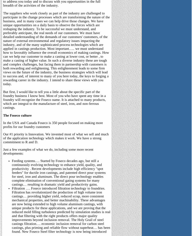
Feeding systems…. Started by Foseco decades ago, but still acontinuously evolving technology to enhance yield, quality, andproductivity . Recent developments include high efficiency "spotfeeders" for ductile iron castings, and patented direct pour systemsfor steel, iron and aluminum. The direct pour technology enablescomplete elimination of conventional gating systems for manycastings… resulting in dramatic yield and productivity gains.Filtration …. Foseco introduced filtration technology to foundries.Filtration has revolutionized the production of high volume ironcastings… providing higher yield, reduced scrap, more consistentmechanical properties, and better machinability. These advantagesare now being extended to high volume aluminum castings, withunique products for these applications, and we are proving that thereduced mold filling turbulence predicted by simulation studies is realand that filtering with the right products offers major qualityimprovements beyond inclusion removal. The Holy Grail of steelcastings filtration…. economic inclusion removal for carbon steelcastings, plus priming and reliable flow without superheat… has beenfound. New Foseco Steel filter technology is now being introduced

The Ductile Iron News - Opportunities in Metal Casting
file:///C|/WEBSHARE/062013/magazine/2002_3/opportunities.htm[7/1/2013 9:23:30 AM]
which meets these critical needs.Insulating ladle lining systems for Steel and for Iron. Another Fosecoinnovation which provides the benefits of precise pouringtemperature control, reduced tap temperature, reduced non-metallicinclusions, and major energy savings.Iron Stream Inoculation systems which combine patented dispensingequipment and purpose designed stream inoculating alloys to deliverconsistent metallurgical performance and tight process control.Degassing systems for Aluminum, with patented rotor designs. Nowaugmented by the development of on-line hydrogen measurementand real-time process control.Products for the rapidly growing Lost Foam casting process. Fosecois intimately involved in this technology-intensive market. We supplyconsumable lost foam patterns and coatings. In fact Foseco is by farthe largest supplier of externally sourced patterns to North Americanlost foam foundries. Here again innovation is a key strength… withour unique ventless pattern technology and patented copolymerpattern materials which have helped to solve the problem of lustrouscarbon inclusion defects in Lost Foam iron casting.Application Engineering and simulation software for feeding andgating system optimization and for filter selection and placement. Inaddition to on-site technical support we provide our customers withthe tools they need to obtain maximum economic gain from investingin our products.
These are products…. but we know that our real business strength is ourpeople and the commitment of those people to the single goal of improvingour customers' businesses.
A business is defined by its culture and its values…they set behavioralexpectations which transcend organizational issues. Ours:
Focus on customer needs.Innovate through customer partnershipsInvest in R and DThink global, act localBe flexible, move fastHire the best people, give them the best training,… then expect themto think and empower them to act.
The best people, for Foseco, has included a large number of FEF alumni.Some have passed through the Foseco organization and gone on to successin other roles in the industry. Some have joined us after gaining experiencewith foundries. And some have started their careers with us and developedtheir careers to date in our organization. I know that all have contributedgreatly to our business and to the industry as a whole. A recent countshowed that we currently have 9 FEF alumni in the Foseco organization. Ipersonally had a tough act to follow around 4 years ago when I succeededan FEF alumnus as CEO here. In addition Foseco continues to activelysupport the FEF internship program. In the past 10 years approximately 30FEF students have interned at our North America headquarters inCleveland, and a number of these were subsequently recruited to start theircareers with us. We like to think that we can provide a very valuableopportunity to overview the way the industry works effectively with itssuppliers in the development and application of manufacturing technology.
That's our culture. There are a lot of different business cultures discernablein our customer base, but interestingly many of the most successful foundryorganizations seem to share many of our core values. Of course, it couldalso be true that we have learned that to be successful we must emulate the
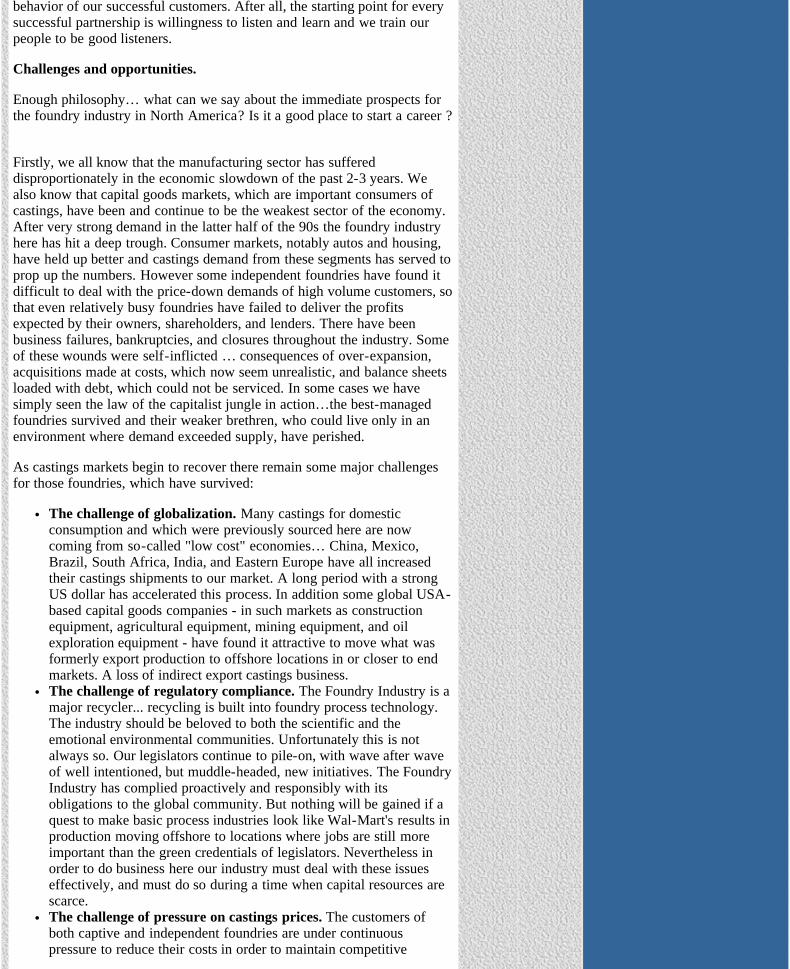
The Ductile Iron News - Opportunities in Metal Casting
file:///C|/WEBSHARE/062013/magazine/2002_3/opportunities.htm[7/1/2013 9:23:30 AM]
behavior of our successful customers. After all, the starting point for everysuccessful partnership is willingness to listen and learn and we train ourpeople to be good listeners.
Challenges and opportunities.
Enough philosophy… what can we say about the immediate prospects forthe foundry industry in North America? Is it a good place to start a career ?
Firstly, we all know that the manufacturing sector has suffereddisproportionately in the economic slowdown of the past 2-3 years. Wealso know that capital goods markets, which are important consumers ofcastings, have been and continue to be the weakest sector of the economy.After very strong demand in the latter half of the 90s the foundry industryhere has hit a deep trough. Consumer markets, notably autos and housing,have held up better and castings demand from these segments has served toprop up the numbers. However some independent foundries have found itdifficult to deal with the price-down demands of high volume customers, sothat even relatively busy foundries have failed to deliver the profitsexpected by their owners, shareholders, and lenders. There have beenbusiness failures, bankruptcies, and closures throughout the industry. Someof these wounds were self-inflicted … consequences of over-expansion,acquisitions made at costs, which now seem unrealistic, and balance sheetsloaded with debt, which could not be serviced. In some cases we havesimply seen the law of the capitalist jungle in action…the best-managedfoundries survived and their weaker brethren, who could live only in anenvironment where demand exceeded supply, have perished.
As castings markets begin to recover there remain some major challengesfor those foundries, which have survived:
The challenge of globalization. Many castings for domesticconsumption and which were previously sourced here are nowcoming from so-called "low cost" economies… China, Mexico,Brazil, South Africa, India, and Eastern Europe have all increasedtheir castings shipments to our market. A long period with a strongUS dollar has accelerated this process. In addition some global USA-based capital goods companies - in such markets as constructionequipment, agricultural equipment, mining equipment, and oilexploration equipment - have found it attractive to move what wasformerly export production to offshore locations in or closer to endmarkets. A loss of indirect export castings business.The challenge of regulatory compliance. The Foundry Industry is amajor recycler... recycling is built into foundry process technology.The industry should be beloved to both the scientific and theemotional environmental communities. Unfortunately this is notalways so. Our legislators continue to pile-on, with wave after waveof well intentioned, but muddle-headed, new initiatives. The FoundryIndustry has complied proactively and responsibly with itsobligations to the global community. But nothing will be gained if aquest to make basic process industries look like Wal-Mart's results inproduction moving offshore to locations where jobs are still moreimportant than the green credentials of legislators. Nevertheless inorder to do business here our industry must deal with these issueseffectively, and must do so during a time when capital resources arescarce.The challenge of pressure on castings prices. The customers ofboth captive and independent foundries are under continuouspressure to reduce their costs in order to maintain competitive
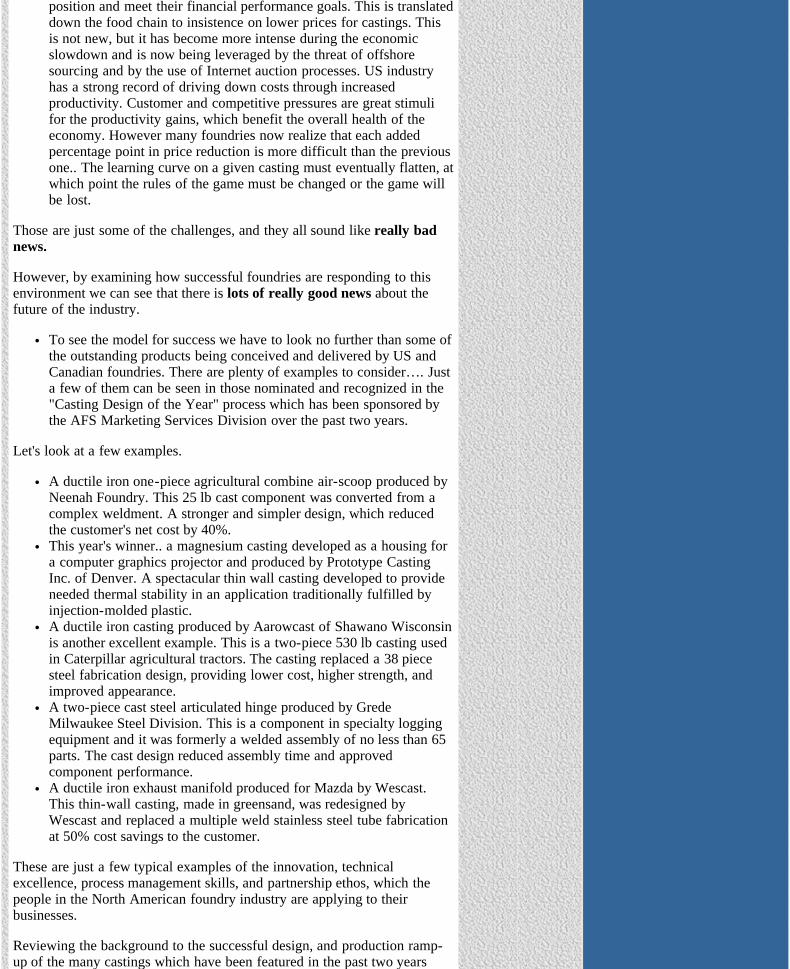
The Ductile Iron News - Opportunities in Metal Casting
file:///C|/WEBSHARE/062013/magazine/2002_3/opportunities.htm[7/1/2013 9:23:30 AM]
position and meet their financial performance goals. This is translateddown the food chain to insistence on lower prices for castings. Thisis not new, but it has become more intense during the economicslowdown and is now being leveraged by the threat of offshoresourcing and by the use of Internet auction processes. US industryhas a strong record of driving down costs through increasedproductivity. Customer and competitive pressures are great stimulifor the productivity gains, which benefit the overall health of theeconomy. However many foundries now realize that each addedpercentage point in price reduction is more difficult than the previousone.. The learning curve on a given casting must eventually flatten, atwhich point the rules of the game must be changed or the game willbe lost.
Those are just some of the challenges, and they all sound like really badnews.
However, by examining how successful foundries are responding to thisenvironment we can see that there is lots of really good news about thefuture of the industry.
To see the model for success we have to look no further than some ofthe outstanding products being conceived and delivered by US andCanadian foundries. There are plenty of examples to consider…. Justa few of them can be seen in those nominated and recognized in the"Casting Design of the Year" process which has been sponsored bythe AFS Marketing Services Division over the past two years.
Let's look at a few examples.
A ductile iron one-piece agricultural combine air-scoop produced byNeenah Foundry. This 25 lb cast component was converted from acomplex weldment. A stronger and simpler design, which reducedthe customer's net cost by 40%.This year's winner.. a magnesium casting developed as a housing fora computer graphics projector and produced by Prototype CastingInc. of Denver. A spectacular thin wall casting developed to provideneeded thermal stability in an application traditionally fulfilled byinjection-molded plastic.A ductile iron casting produced by Aarowcast of Shawano Wisconsinis another excellent example. This is a two-piece 530 lb casting usedin Caterpillar agricultural tractors. The casting replaced a 38 piecesteel fabrication design, providing lower cost, higher strength, andimproved appearance. A two-piece cast steel articulated hinge produced by GredeMilwaukee Steel Division. This is a component in specialty loggingequipment and it was formerly a welded assembly of no less than 65parts. The cast design reduced assembly time and approvedcomponent performance. A ductile iron exhaust manifold produced for Mazda by Wescast.This thin-wall casting, made in greensand, was redesigned byWescast and replaced a multiple weld stainless steel tube fabricationat 50% cost savings to the customer.
These are just a few typical examples of the innovation, technicalexcellence, process management skills, and partnership ethos, which thepeople in the North American foundry industry are applying to theirbusinesses.
Reviewing the background to the successful design, and production ramp-up of the many castings which have been featured in the past two years
The Ductile Iron News - Opportunities in Metal Casting
file:///C|/WEBSHARE/062013/magazine/2002_3/opportunities.htm[7/1/2013 9:23:30 AM]
serves to highlight the effective use which successful foundries are makingof sophisticated computer techniques for predicting the results of thermaland physical stress , for simulation of mold fill and solidification, and forrapid prototyping. Many of these castings also involved the creativecontributions from a whole spectrum of foundry suppliers, from softwaredevelopers, to consumables companies and equipment suppliers.
Delivering more profit for a customer is not limited to high volume,design intensive, castings. There are a number of very successfulshort run jobbing foundries which have developed business modelsbuilt on fast response times for existing patterns and for new limitedproduction castings… often in specialized alloys and includingcoordination of third party heat treating and machining services.These foundries have developed packages of skills and customer-friendly services providing end-to-end value which eliminates the"$s per pound" quoting treadmill.Success is also not limited to foundries with external customers. Forexample, the story of GM Powertrain Division development of thehigh performance Vortec series of aluminum light truck engines firstunveiled in the wildly successful new Trailblazer SUV has been welldocumented. Concurrent design of a revolutionary new engine, andthe foundry for production of its primary castings in the lost foamprocess which was chosen, is a remarkable achievement. The scienceof casting, and the contributions the dedicated manufacturingengineers who applied that science, are at the core of one of the mostcommercially important projects undertaken by GM.Environmental and regulatory challenges are being met head-on byfoundries who have embraced the position that good environmentalimpact is good business and improved working conditions pay bigdividends. For example, there is a surge of investment in cleaningroom automation. In the new generation of cleaning rooms entry-level foundry production employees need no longer be challenged byphysically demanding labor. Many of the most progressive foundrieshave set environmental goals far exceeding those required orcontemplated by regulation and have invested capital resourceswhose justification is founded in the belief that well managedfoundry operations will continue to play a vital role in the economy.
Lots of good news…. all involving foundries succeeding by applyinginnovation to their casting processes and their business processes in orderto deliver increased profits for their external or internal customers. Thereare hundreds of such stories developing daily in US foundries. What dothey tell us about the future?
They tell us that castings markets are not limited solely to thoseapplications whose have traditionally been met by castings.They tell us that the future is not in doing the same things in thesame way. Absence of change is a prescription for beingcommoditized out of business. There is no casting which can not beimproved to provide more value…. Just look at what WaupacaFoundry is doing in development of compacted graphite iron as amaterial for severe service truck brake drums. A simple "commodity"casting becomes a lighter, stronger, more durable component… muchmore valuable to the truck builder than a 20% price cut from aChinese foundry.They tell us that the performance of foundries has to be measured interms of value added for customers, not in terms of tonnageproduced. The days when a good foundry business consisted ofmaking more tonnage of the same castings, to the samespecifications, and with the same performance as 5 or 10 years ago,

The Ductile Iron News - Opportunities in Metal Casting
file:///C|/WEBSHARE/062013/magazine/2002_3/opportunities.htm[7/1/2013 9:23:30 AM]
are long gone. Those are commodity castings, or soon will be. Theoffshore producers can make those castings, and will be pleased to doso at prices 5%, 10%, or 20% below ours. If we let our customersbelieve that is what they need, that may be what they will buy. Toparticipate in that "commodity" segment US foundries shouldprobably be operating, or outsourcing, offshore.They tell us that success lies in partnering with customers, and withsuppliers. Good profitable foundry business is being established byUS foundries who are collaborating with their customers in designand development of cast components, and with their suppliers ininnovative process technology to optimize the performance andproduction cost of those castings. At Foseco we are privileged towork with many of the foundries whose business models aredelivering success. We have the opportunity to see successful USfoundry people at work.. and it is impressive.Offshore "price per pound" casting suppliers can not compete withcustomers who want to be served under the new rules .The new rulesdemand close, responsive, continuous and iterative communicationsbetween casting customer, casting producer, and suppliers.Innovative and well-managed North American foundries will thrivein this environment.
In a moment we can look at what this all means for those of you who herebecause you are serious about embarking upon careers in this industry.
First, we should recognize that there are other options for application of anexpensive education and maybe a few comparisons are in order. After all,how can this ancient industry be compared favorably to the excitement,which is available in the go-go worlds of telecom, energy trading, mediaconglomerates, and creative auditing?
Let us call them the "New Economy" businesses.
A few specific comparisons for your consideration.
Top Ten clues to tell you whether you are working in a Foundry or in aNew Economy cubicle.
Clue #1In the Foundry: You can labor hard for 10 years and get to be a FoundryManager.In the Cube: You can make Chief Financial officer in just 6 months…then do 10 years hard labor.
Clue #2In the Foundry: You have the opportunity to market near net shapeInvestment Castings.In the Cube: You have the opportunity to market near net worthlessInvestments.
Clue #3In the Foundry: You learn that increased burn rate is good. It means thatyou are getting steel castings through the cleaning room faster.In the Cube: You learn that increased burn rate can be bad. Pay thosebonuses before the cash runs out!
Clue #4In the Foundry: When you speak in public you are introduced by the AFSprogram chairman, after dinner.In the New Cube: When you speak in public you are introduced by…"Will the defendant please rise."?
The Ductile Iron News - Opportunities in Metal Casting
file:///C|/WEBSHARE/062013/magazine/2002_3/opportunities.htm[7/1/2013 9:23:30 AM]
Clue #5In the Foundry: You are protected in the workplace by your hardhat andsafety glassesIn the Cube: You are protected in the workplace by the Fifth Amendment
Clue #6In the Foundry: You can watch scrap melt down.In the Cube: You can watch your 401-K melt down.
Clue #7In the Foundry: You will need Capital budgets for the melt shop,molding, and the cleaning room.In the Cube: You will need just one Capital budget… for paper shredders.
Clue #8In the Foundry: You can learn how to improve business results byinventing products and processes.In the Cube: You can learn how to improve business results by inventingcustomers and sales.
Clue #9In the Foundry: Charge sheet… generated by the Melt ShopSuperintendentIn the Cube: Charge sheet…. Generated by the Grand Jury foreman.
And finally…
Clue #10In the Foundry: Your parents can easily explain what you do to theirfriends.In the cube: They will have to explain why you have moved back intoyour old room.
On the whole I think you will agree with me that the Foundry Industry, aspart of the "New Old Economy" has more career attractions than some ofthese "New Economy" businesses. Boring is better… if it means owningreal assets, making and selling real products to real customers, andemploying people who are dedicated to personal growth throughcontributing to improvement of the economy and to the quality of life intheir communities.
In conclusion:
The Foundry Industry holds a rewarding future for participants whoknow the elements of success:
1. A focus on delivering profits for customers2. Innovation3. Leveraging technology4. Flexibility5. Development of Partnerships6. Hiring and developing the best people.
This applies throughout the industry, to both producers and tosuppliers.The Foundry Industry needs future leaders who are ready to thrive inthis environment. There will be Big Prizes for the Winners
You will make your own judgments on whether specific industry playersare potential winners... one good clue is that the potential winners are likelyto be recruiting from the ranks of FEF students.

The Ductile Iron News - Opportunities in Metal Casting
file:///C|/WEBSHARE/062013/magazine/2002_3/opportunities.htm[7/1/2013 9:23:30 AM]
I have enjoyed this opportunity to share some ideas with you. Good luckwith your careers!
View Ductile Iron Related Publications
Located in Strongsville, Ohio, USA15400 Pearl Road, Suite 234; Strongsville,Ohio 44136 Billing Address: 2802 Fisher Road, Columbus, Ohio 43204 Phone (440) 665-3686; Fax (440) 878-0070email:[email protected]

The Ductile Iron News - FEF College Industry Conference
file:///C|/WEBSHARE/062013/magazine/2002_3/fefconference.htm[7/1/2013 9:23:28 AM]
To Promote the production and application of ductile iron castings Issue 3, 2002
FEF College Industry Conference
FOR IMMEDIATE RELEASE NOVEMBER, 2002FEF COLLEGE INDUSTRY CONFERENCE
A total of 370 people-249 industry and university people attended thisyear's conference, along with 121 student delegates representing FEF's 32schools. This unique conference brought together top industry executives,FEF Board Members, Key Professors, university officials and top studentdelegates-all interested in metal casting. Bob Smillie of Nemak was theconference chairman.
The FEF Annual Banquet was held at the Crystal Garden restaurant onNavy Pier in Chicago on Thursday night, November 7. Special FEFrecognition awards were presented to: Foundry of the year-John DeereFoundry in Waterloo, Iowa; Supplier of the year-Fairmount Minerals inChardon, Ohio; and Society/Association of the year-the Ductile IronSociety. Also, at the banquet, FEF provided the forum for the FoundryManagement & Technology's Hall of Fame awards which were presentedto Paul Carey and Daryl Hoyt. Bruce Dienst of Simpson Technologies wasthe Master of Ceremonies.
During the General Session on Friday, the Keynote address was given byRoger Stanbridge, President of Foseco. This year's three panelists includedAndrea Kay, Quality Engineer at EST Co., Grafton, WI and an FEF scholarfrom Ohio State and Virginia Tech; Pete Carpenter, Foundry Manager atRobert Bosch Corp., St. Joseph, MI and an FEF scholar from the MichiganTech; and Bill Powell, Manager of Melt & Metallurgy of WaupacaFoundry, Waupaca, WI and an FEF scholar from the University ofWisconsin-Madison.
During the Edward C. Hoenicke Memorial Luncheon, the AFS/FEF BoardAward of $6000 was given to FEF Key Professor, Bob Voigt serving atPenn State University. Also given out this year, were 2 gifts, each in theamount of $10,000, from the FEF/Ray Witt Gift Program. These gifts werepresented to Thomas Hahn from Pittsburg State University and Luis Truebafrom Tri-State University.
The Industry Information Session offered students an up-close and personallook at the industry. It also gave the 32 participating companies, who had33 tables, the most cost-effective way to see some of the top metal castingstudents in the country all in one place.
The Awards and Recognition Breakfast speaker was the Chancellor of theUniversity of Wisconsin-Milwaukee, Nancy Zimpher. Following hercomments, 22 delegate scholarships were awarded to the student delegateswho had submitted applications for these awards (see reverse side). Inaddition, one school had a student in the "runner-up" category. Thisstudent will receive an expense-paid trip to the AFS Government AffairsConference in April, 2003. Also highlighted were the four Keith Millis
FEATURES
•Cover Story - Ductile Iron Societyreceives the Society/Association ofthe Year Award - See Photos
• Surface Defects in Iron Castings
• Applications of ADI
• Opportunities in Metal Casting
• FEF College Industry Conference
• Spectrometer Standards
• AFS Trade Commission
DEPARTMENTS
• News Briefs
• Advertisers
• Back Issues
• DIS Home Page
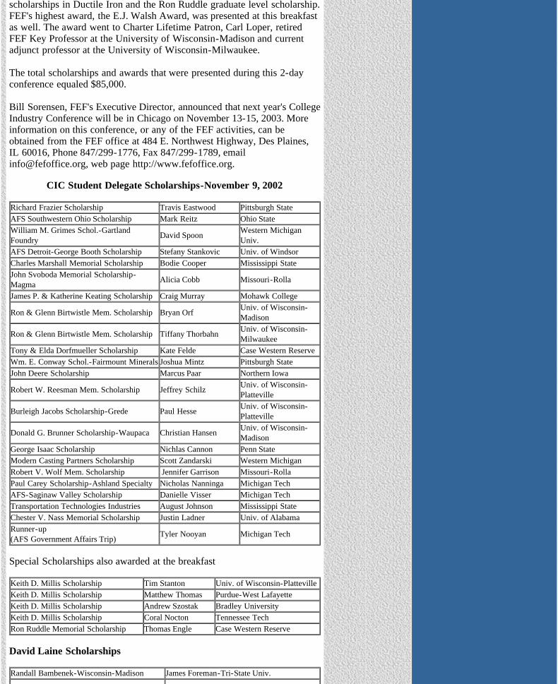
The Ductile Iron News - FEF College Industry Conference
file:///C|/WEBSHARE/062013/magazine/2002_3/fefconference.htm[7/1/2013 9:23:28 AM]
scholarships in Ductile Iron and the Ron Ruddle graduate level scholarship.FEF's highest award, the E.J. Walsh Award, was presented at this breakfastas well. The award went to Charter Lifetime Patron, Carl Loper, retiredFEF Key Professor at the University of Wisconsin-Madison and currentadjunct professor at the University of Wisconsin-Milwaukee.
The total scholarships and awards that were presented during this 2-dayconference equaled $85,000.
Bill Sorensen, FEF's Executive Director, announced that next year's CollegeIndustry Conference will be in Chicago on November 13-15, 2003. Moreinformation on this conference, or any of the FEF activities, can beobtained from the FEF office at 484 E. Northwest Highway, Des Plaines,IL 60016, Phone 847/299-1776, Fax 847/299-1789, [email protected], web page http://www.fefoffice.org.
CIC Student Delegate Scholarships-November 9, 2002
Richard Frazier Scholarship Travis Eastwood Pittsburgh StateAFS Southwestern Ohio Scholarship Mark Reitz Ohio StateWilliam M. Grimes Schol.-GartlandFoundry David Spoon Western Michigan
Univ.AFS Detroit-George Booth Scholarship Stefany Stankovic Univ. of WindsorCharles Marshall Memorial Scholarship Bodie Cooper Mississippi StateJohn Svoboda Memorial Scholarship-Magma Alicia Cobb Missouri-Rolla
James P. & Katherine Keating Scholarship Craig Murray Mohawk College
Ron & Glenn Birtwistle Mem. Scholarship Bryan Orf Univ. of Wisconsin-Madison
Ron & Glenn Birtwistle Mem. Scholarship Tiffany Thorbahn Univ. of Wisconsin-Milwaukee
Tony & Elda Dorfmueller Scholarship Kate Felde Case Western ReserveWm. E. Conway Schol.-Fairmount Minerals Joshua Mintz Pittsburgh StateJohn Deere Scholarship Marcus Paar Northern Iowa
Robert W. Reesman Mem. Scholarship Jeffrey Schilz Univ. of Wisconsin-Platteville
Burleigh Jacobs Scholarship-Grede Paul Hesse Univ. of Wisconsin-Platteville
Donald G. Brunner Scholarship-Waupaca Christian Hansen Univ. of Wisconsin-Madison
George Isaac Scholarship Nichlas Cannon Penn State Modern Casting Partners Scholarship Scott Zandarski Western MichiganRobert V. Wolf Mem. Scholarship Jennifer Garrison Missouri-RollaPaul Carey Scholarship-Ashland Specialty Nicholas Nanninga Michigan TechAFS-Saginaw Valley Scholarship Danielle Visser Michigan TechTransportation Technologies Industries August Johnson Mississippi StateChester V. Nass Memorial Scholarship Justin Ladner Univ. of AlabamaRunner-up (AFS Government Affairs Trip) Tyler Nooyan Michigan Tech
Special Scholarships also awarded at the breakfast
Keith D. Millis Scholarship Tim Stanton Univ. of Wisconsin-PlattevilleKeith D. Millis Scholarship Matthew Thomas Purdue-West LafayetteKeith D. Millis Scholarship Andrew Szostak Bradley UniversityKeith D. Millis Scholarship Coral Nocton Tennessee TechRon Ruddle Memorial Scholarship Thomas Engle Case Western Reserve
David Laine Scholarships
Randall Bambenek-Wisconsin-Madison James Foreman-Tri-State Univ.

The Ductile Iron News - FEF College Industry Conference
file:///C|/WEBSHARE/062013/magazine/2002_3/fefconference.htm[7/1/2013 9:23:28 AM]
John Harm-Ohio State James Heller-Wisconsin-PlattevilleDan Szablewski-Univ. of Windsor Nicole Weimer-Wisconsin-MadisonDan Medvec-St. Thomas (Spring '02) Coral Nocton-Tennessee Tech (Spring '02)
View Ductile Iron Related Publications
Located in Strongsville, Ohio, USA15400 Pearl Road, Suite 234; Strongsville,Ohio 44136 Billing Address: 2802 Fisher Road, Columbus, Ohio 43204 Phone (440) 665-3686; Fax (440) 878-0070email:[email protected]

The Ductile Iron News - Photos
file:///C|/WEBSHARE/062013/magazine/2002_3/billwendy.htm[7/1/2013 9:23:27 AM]
Photos from the FEF College Industry Conference
Bill and Wendy Sorensen

The Ductile Iron News - Photos
file:///C|/WEBSHARE/062013/magazine/2002_3/boblinda.htm[7/1/2013 9:23:27 AM]
Photos from the FEF College Industry Conference
Bob and Linda Steele

The Ductile Iron News - Photos
file:///C|/WEBSHARE/062013/magazine/2002_3/bobvoigt1.htm[7/1/2013 9:23:27 AM]
Photos from the FEF College Industry Conference
Ray Monroe's wife and Bob Voigt

The Ductile Iron News - Photos
file:///C|/WEBSHARE/062013/magazine/2002_3/bobvoigt2.htm[7/1/2013 9:23:28 AM]
Photos from the FEF College Industry Conference
____________ and Bob Voigt

The Ductile Iron News - Photos
file:///C|/WEBSHARE/062013/magazine/2002_3/doynelinda.htm[7/1/2013 9:23:28 AM]
Photos from the FEF College Industry Conference
Doyne and Linda Chartrau

The Ductile Iron News - Photos
file:///C|/WEBSHARE/062013/magazine/2002_3/jackclare.htm[7/1/2013 9:23:29 AM]
Photos from the FEF College Industry Conference
Clare and Jack Hall
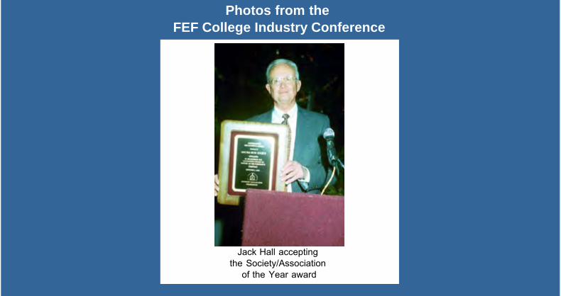
The Ductile Iron News - Photos
file:///C|/WEBSHARE/062013/magazine/2002_3/jackplaque.htm[7/1/2013 9:23:30 AM]
Photos from the FEF College Industry Conference
Jack Hall accepting the Society/Association
of the Year award

The Ductile Iron News - Photos
file:///C|/WEBSHARE/062013/magazine/2002_3/pauldean.htm[7/1/2013 9:23:31 AM]
Photos from the FEF College Industry Conference
Paul Carey and Dean Peters
The Ductile Iron News - Photos
file:///C|/WEBSHARE/062013/magazine/2002_3/paulpat.htm[7/1/2013 9:23:31 AM]
Photos from the FEF College Industry Conference
Paul and Pat Carey

The Ductile Iron News - Photos
file:///C|/WEBSHARE/062013/magazine/2002_3/profdoru.htm[7/1/2013 9:23:32 AM]
Photos from the FEF College Industry Conference
Professor Doru Stefanescu and guest

The Ductile Iron News - Spectrometer Standards
file:///C|/WEBSHARE/062013/magazine/2002_3/spectro.htm[7/1/2013 9:23:33 AM]
To Promote the production and application of ductile iron castings Issue 3, 2002
Spectrometer StandardsBack to Issue 3, 2002 Index
Overview of Spark Emission (OE) Instrumentation and Points to Consider
Related to Cast Iron Analysis+
"Spectrometer Standards/Samples for Spark Emission"
Brad Cooley - OE Laboratory Manager - 313-271-5711(Revised from a Power Point Presentation)
1. ThermoARL
Thermo ARL - Founded in 1934
Spark Excitation
Easy Operation
Simple Preparation
Fast Analysis
Majors to Traces
Precise Results
Accurate Results
2. ThermoARL
ARL Metals AnalyzersFEATURES:
1 Meter Focal Length SpectrometerDirect Reader (PMT Based)HiRep Source (400 Hz)Completely Enclosed Cabinetry
BENEFITS:
Optimum Line Choice/Resolution (in 1 cell)All Elements + C, P, S, N - High PerformanceOptimum Precision and SensitivityTolerates Rugged Environment
3. ThermoARL
Getting Good Results with Spark EmissionKey Areas to Consider
1. Sample Taking Procedures - Are they Consistent?
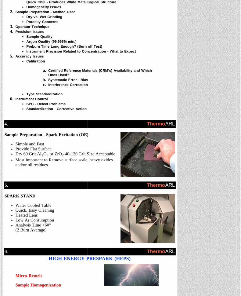
The Ductile Iron News - Spectrometer Standards
file:///C|/WEBSHARE/062013/magazine/2002_3/spectro.htm[7/1/2013 9:23:33 AM]
Quick Chill - Produces White Metallurgical StructureHomogeneity Issues
2. Sample Preparation - Method UsedDry vs. Wet GrindingPorosity Concerns
3. Operator Technique4. Precision Issues
Sample QualityArgon Quality (99.995% min.)Preburn Time Long Enough? (Burn off Test)Instrument Precision Related to Concentration - What to Expect
5. Accuracy IssuesCalibration
a. Certified Reference Materials (CRM’s) Availability and WhichOnes Used?
b. Systematic Error - Biasc. Interference Correction
Type Standardization6. Instrument Control
SPC - Detect ProblemsStandardization - Corrective Action
4. ThermoARL
Sample Preparation - Spark Excitation (OE)
Simple and FastProvide Flat SurfaceDry 60 Grit Al2O3 or ZrO2 40-120 Grit Size AcceptableMost Important to Remove surface scale, heavy oxidesand/or oil residues
5. ThermoARL
SPARK STAND
Water Cooled TableQuick, Easy CleaningHeated LensLow Ar ConsumptionAnalysis Time <60" (2 Burn Average)
6. ThermoARLHIGH ENERGY PRESPARK (HEPS)
Micro-Remelt
Sample Homogenization

The Ductile Iron News - Spectrometer Standards
file:///C|/WEBSHARE/062013/magazine/2002_3/spectro.htm[7/1/2013 9:23:33 AM]
Optimizes Precision
7. ThermoARL
Spectrometer - Optical Light Path
8. ThermoARLSPECTROMETER
FEATURE:
1 Meter Focal LengthTemperature Controlled (Above ambient + 0.1o)Shock MountedClean Vacuum System
BENEFIT:
Optimum Lines in 1 CellLong Term StabilityHigh Sensitivity and Stability
9. ThermoARLLong-term Stability in
Spark AES Analytical Importance
Key influence on precision, accuracy and speed of analysisTime spent in optical profiling and drift correction is analytical time lostFrequent drift correction can contribute to errorMetals production depends on stable analytical instruments to ensurethe process is in control

The Ductile Iron News - Spectrometer Standards
file:///C|/WEBSHARE/062013/magazine/2002_3/spectro.htm[7/1/2013 9:23:33 AM]
10. ThermoARL
Integrated SPC
Control Chart
11. ThermoARL
SPC Rules
Out of Control Limits
12. ThermoARL
SPC Rules
Bias
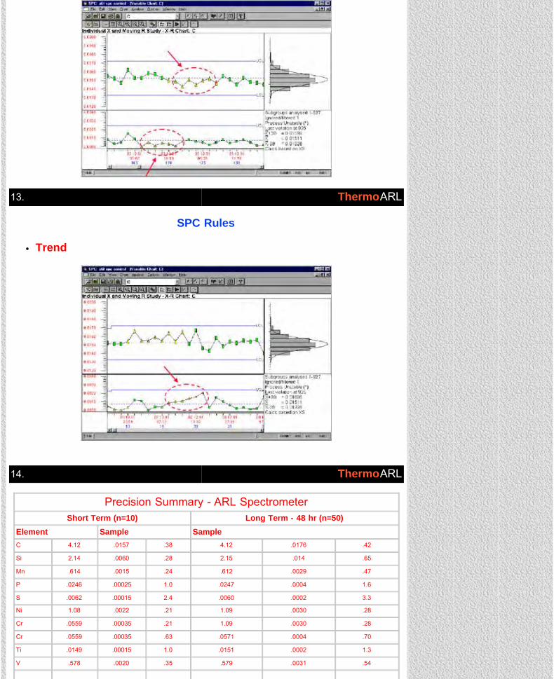
The Ductile Iron News - Spectrometer Standards
file:///C|/WEBSHARE/062013/magazine/2002_3/spectro.htm[7/1/2013 9:23:33 AM]
13. ThermoARL
SPC Rules
Trend
14. ThermoARL
Precision Summary - ARL SpectrometerShort Term (n=10) Long Term - 48 hr (n=50)
Element Sample SampleC 4.12 .0157 .38 4.12 .0176 .42
Si 2.14 .0060 .28 2.15 .014 .65
Mn .614 .0015 .24 .612 .0029 .47
P .0246 .00025 1.0 .0247 .0004 1.6
S .0062 .00015 2.4 .0060 .0002 3.3
Ni 1.08 .0022 .21 1.09 .0030 .28
Cr .0559 .00035 .21 1.09 .0030 .28
Cr .0559 .00035 .63 .0571 .0004 .70
Ti .0149 .00015 1.0 .0151 .0002 1.3
V .578 .0020 .35 .579 .0031 .54

The Ductile Iron News - Spectrometer Standards
file:///C|/WEBSHARE/062013/magazine/2002_3/spectro.htm[7/1/2013 9:23:33 AM]
Cu .0251 .00015 .60 .0254 .0002 .61
Al .044 .0003 .68 .045 .0003 .61
Mg .078 .0018 2.4 .080 .0032 3.9
B .0008 .000045 5.6 .0009 .000059 6.6
Sn .0598 .0004 .67 .0601 .0007 1.2
Pb .0032 .0002 5.7 .0031 .0002 6.4
Average RSD: (*) 1.5 1.9(*)
15. ThermoARLLong Term Stability
Chilled Cast Iron
CAST IRON CONTROL SAMPLE WITHOUT STANDARDIZATION
The global average precision of these elements over 5 days is 0.52 % RSD
16. ThermoARL
Long-term StabilityProduction Samples
Steel Control Sample analyzed 2x each day in an actual working environment of a major steel company
17. ThermoARLSpectrometer Standards/Samples For Spark Emission (Terminology Used)
Standard / Sample Categories Uses
Primary Standards*Certified Reference Material (CRM's)*Standard Reference Material*Calibration Standards*Reference Material (RM)^Type Standards*♦
Secondary Standards
Certificate of Analysis - Rigorous Testing*Used for Calibration of Instruments Only*Expensive and Limited*Less Rigorous Testing - Still Useful^To Fine Tune Instrument Calibration *♦
To Correct For Instrument Changes Over TimePrerequisite is to be Homogeneous

The Ductile Iron News - Spectrometer Standards
file:///C|/WEBSHARE/062013/magazine/2002_3/spectro.htm[7/1/2013 9:23:33 AM]
Setting-Up Samples or StandardsDrift Correction Samples or StandardsStandardization Samples or StandardsRe-Calibration Samples or Standards
Control Samples or StandardsQuality Control Samples or StandardsCheck Samples or Standards
Good Intensity Spread (Low and High)Approximate Analysis Given
To Monitor Instrument Performance at User DefinedTime IntervalsShould be Secondary Material - Homogeneous
18. ThermoARL
Certificate of AnalysisSTANDARD REFERENCE MATERIALS
1140, 1141, 1142Ductile Iron Standards
SRM No. 1140Ductile Iron 1
1141Ductile Iron 2
1142Ductile Iron 3
Element PercentCarbon 3.18 3.64 2.94Manganese 0.725 0.480 0.183Phosphorous .0070 .073 .210Sulfur .010 .020 .015Sillicon 1.92 1.11 3.33Copper 0.096 0.204 1.02Nickel .028 .548 1.63Chromium .030 .138 .055Vanadium .030 .009 .006Molybdenum .095 .051 .023Titanium .096 .013 .008Aluminum (.01) (.005) .089Arsenic .072 .036 .010Magnesium .019 .044 .097Cerium (.09) (.05) (.015)Yttrium (<.002) .040 .01Lead .0052 (.0009) (.0005)Bismuth .0015 (.00008) (.00002)
*Values in parenthesis are not certified but are provided foradditional information on the composition.
SIZE AND METALLURGICAL CONDITION: Samples areapproximately 1 1/4 inches (3.2 cm) square and 1/2 inch (1.3 cm)thick; they were chill-cast by a rapid unidirectional solidificationtechnique.
CERTIFIED PORTION: The certified portion for each sample is thatextending upward 5/16 inch (0.8 cm) from the chill-cast or testsurface (the largest surface opposite the numbered surface). Thisportion only was analyzed in the cooperative program forcertification.
FINAL CERTIFICATION: The value listed for an element is the bestestimate of the true value based on the results of the cooperativeanalytical program. The value listed is not expected to deviate fromthe true value by more than + 1 in the last significant figurereported; for a subscript figure, the deviation is not expected to bemore than + 5 in the subscript figure. Based on the results ofhomogeneity testing, maximum variations within and amongsamples are estimated less than the accuracy figures given above.
Washington, D.C. 20234 J. Paul Cali, Acting ChiefFebruary 24, 1970 Office of Standard Reference
Materials
PLANNING, PREPARATION, TESTING, ANALYSIS: The three ductileiron standards are made available as a result of the cooperative program,between the National Bureau of Standards and the American Cast IronPipe Company, The standards were developed at the request of the DuctileIron Society and the American foundrymen's Society.
The material for the standards was melted and cast at the American CastIron Pipe Company, Birmingham, Alabama, with use of the NBS chill-cast mold assembly. The preparation and homogeneity testing was similarto that described in NBS Misc. Publ. 260-1, Standard ReferenceMaterials: Preparation of NBS White Cast Iron SpectrochemicalStandards, Robert E. Michaelis and LeRoy L. Wyman, June 19, 1964.
Homogeneity testing was performed at NBS by D. M. Bouchette and wasfound to be satisfactory for the elements certified.
Cooperative analyses for certification were performed at the American Cast Iron Pipe Company, Birmingham, Alabama by I. Glaze, J. B. Hobby,W. R. Kennedy, and R. N. Smith.
Analyses for final certification at the National Bureau of Standards wereperformed in the laboratories of the Analytic Chemistry Division by J. R.Baldwin, D. M. Bouchette, M. M. Darr, E. L. Garner, P. D. LaFleur, G. J.Lutz, E. J. Maienthal, M. Margoshes, L. I. McClendon, T. J. Murphy, T.C. Rains, S. D. Rasberry, T. A. Rush, B. A. Thompson, and J. L. Weber,Jr.
Technical measurements performed at NBS for final certification werecoordinated by J. I. Shultz and J. L. Weber, Jr. under the chairmanship ofB.F. Scribner.
The technical and support aspects involved in the preparation, certification,and issuance of these Standard Reference Materials were coordinatedthrough the Office of Standard Reference materials by R. E. Michaelis.
CAUTIONS:
1. Determinations made on other than the chill-cast or test surfaceare not recommended because of the unidirectional solidificationstructure.
2. These chill-cast standards are designed for calibration in theanalysis of samples prepared in the same manner; samplesprepared by other casting techniques or having other than awhite structure may result in considerable bias.
3. Because the samples exhibit a change with respect to thecolumnar structure, both among standards and from bottom totop of the certified portion of the samples, the surfacepreparation for x-ray spectroscopic analysis may be critical. (Ametallographic polishing technique is recommended).
4. Because of the poor heat conductivity of the ductile irons,difference in volatility rates for certain elements in emissionspectroscopic analysis may occur depending on the location ofthe burn and the source parameters.
(over)
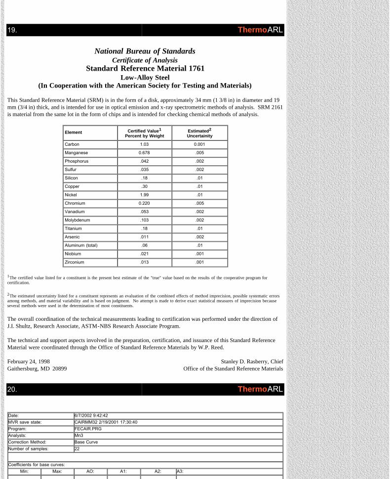
The Ductile Iron News - Spectrometer Standards
file:///C|/WEBSHARE/062013/magazine/2002_3/spectro.htm[7/1/2013 9:23:33 AM]
19. ThermoARL
National Bureau of StandardsCertificate of Analysis
Standard Reference Material 1761Low-Alloy Steel
(In Cooperation with the American Society for Testing and Materials)
This Standard Reference Material (SRM) is in the form of a disk, approximately 34 mm (1 3/8 in) in diameter and 19mm (3/4 in) thick, and is intended for use in optical emission and x-ray spectrometric methods of analysis. SRM 2161is material from the same lot in the form of chips and is intended for checking chemical methods of analysis.
Element Certified Value1Percent by Weight
Estimated2Uncertainity
Carbon 1.03 0.001
Manganese 0.678 .005
Phosphorus .042 .002
Sulfur .035 .002
Silicon .18 .01
Copper .30 .01
Nickel 1.99 .01
Chromium 0.220 .005
Vanadium .053 .002
Molybdenum .103 .002
Titanium .18 .01
Arsenic .011 .002
Aluminum (total) .06 .01
Niobium .021 .001
Zirconium .013 .001
1The certified value listed for a constituent is the present best estimate of the "true" value based on the results of the cooperative program forcertification.
2The estimated uncertainty listed for a constituent represents an evaluation of the combined effects of method imprecision, possible systematic errorsamong methods, and material variability and is based on judgment. No attempt is made to derive exact statistical measures of imprecision becauseseveral methods were used in the determination of most constituents.
The overall coordination of the technical measurements leading to certification was performed under the direction ofJ.I. Shultz, Research Associate, ASTM-NBS Research Associate Program.
The technical and support aspects involved in the preparation, certification, and issuance of this Standard ReferenceMaterial were coordinated through the Office of Standard Reference Materials by W.P. Reed.
February 24, 1998 Stanley D. Rasberry, ChiefGaithersburg, MD 20899 Office of the Standard Reference Materials
20. ThermoARL
Date: 6/7/2002 9:42:42MVR save state: CAIRMM32 2/19/2001 17:30:40Program: FECAIR.PRGAnalysts: Mn3Correction Method: Base CurveNumber of samples: 22
Coefficients for base curves:Min: Max: AO: A1: A2: A3:
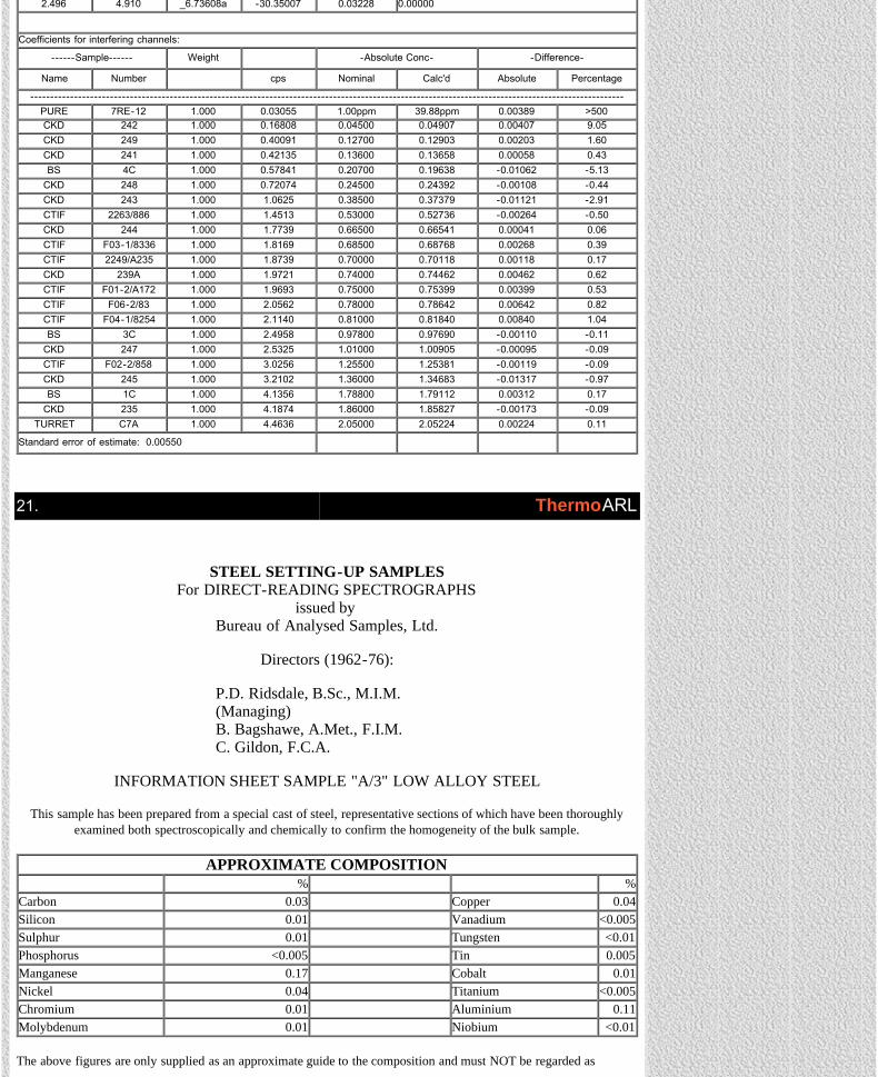
The Ductile Iron News - Spectrometer Standards
file:///C|/WEBSHARE/062013/magazine/2002_3/spectro.htm[7/1/2013 9:23:33 AM]
2.496 4.910 _6.73608a -30.35007 0.03228 0.00000
Coefficients for interfering channels:
------Sample------ Weight -Absolute Conc- -Difference-
Name Number cps Nominal Calc'd Absolute Percentage
-----------------------------------------------------------------------------------------------------------------------------------------------------PURE 7RE-12 1.000 0.03055 1.00ppm 39.88ppm 0.00389 >500CKD 242 1.000 0.16808 0.04500 0.04907 0.00407 9.05CKD 249 1.000 0.40091 0.12700 0.12903 0.00203 1.60CKD 241 1.000 0.42135 0.13600 0.13658 0.00058 0.43BS 4C 1.000 0.57841 0.20700 0.19638 -0.01062 -5.13
CKD 248 1.000 0.72074 0.24500 0.24392 -0.00108 -0.44CKD 243 1.000 1.0625 0.38500 0.37379 -0.01121 -2.91CTIF 2263/886 1.000 1.4513 0.53000 0.52736 -0.00264 -0.50CKD 244 1.000 1.7739 0.66500 0.66541 0.00041 0.06CTIF F03-1/8336 1.000 1.8169 0.68500 0.68768 0.00268 0.39CTIF 2249/A235 1.000 1.8739 0.70000 0.70118 0.00118 0.17CKD 239A 1.000 1.9721 0.74000 0.74462 0.00462 0.62CTIF F01-2/A172 1.000 1.9693 0.75000 0.75399 0.00399 0.53CTIF F06-2/83 1.000 2.0562 0.78000 0.78642 0.00642 0.82CTIF F04-1/8254 1.000 2.1140 0.81000 0.81840 0.00840 1.04BS 3C 1.000 2.4958 0.97800 0.97690 -0.00110 -0.11
CKD 247 1.000 2.5325 1.01000 1.00905 -0.00095 -0.09CTIF F02-2/858 1.000 3.0256 1.25500 1.25381 -0.00119 -0.09CKD 245 1.000 3.2102 1.36000 1.34683 -0.01317 -0.97BS 1C 1.000 4.1356 1.78800 1.79112 0.00312 0.17
CKD 235 1.000 4.1874 1.86000 1.85827 -0.00173 -0.09TURRET C7A 1.000 4.4636 2.05000 2.05224 0.00224 0.11
Standard error of estimate: 0.00550
21. ThermoARL
STEEL SETTING-UP SAMPLESFor DIRECT-READING SPECTROGRAPHS
issued by Bureau of Analysed Samples, Ltd.
Directors (1962-76):
P.D. Ridsdale, B.Sc., M.I.M.(Managing)B. Bagshawe, A.Met., F.I.M.C. Gildon, F.C.A.
INFORMATION SHEET SAMPLE "A/3" LOW ALLOY STEEL
This sample has been prepared from a special cast of steel, representative sections of which have been thoroughlyexamined both spectroscopically and chemically to confirm the homogeneity of the bulk sample.
APPROXIMATE COMPOSITION% %
Carbon 0.03 Copper 0.04Silicon 0.01 Vanadium <0.005Sulphur 0.01 Tungsten <0.01Phosphorus <0.005 Tin 0.005Manganese 0.17 Cobalt 0.01Nickel 0.04 Titanium <0.005Chromium 0.01 Aluminium 0.11Molybdenum 0.01 Niobium <0.01
The above figures are only supplied as an approximate guide to the composition and must NOT be regarded as
The Ductile Iron News - Spectrometer Standards
file:///C|/WEBSHARE/062013/magazine/2002_3/spectro.htm[7/1/2013 9:23:33 AM]
standard figures.
N.B. These samples should not be confused with the Primary Spectroscopic Standards prepared and issued by Bureauof Analysed Samples Ltd.
Newham Hall, Middlesbrough, Cleveland, England March, 1976
ThermoARL
CKD Primary Standards - Low Alloy Cast Iron Calibrations
23. ThermoARL
24. ThermoARL

The Ductile Iron News - Spectrometer Standards
file:///C|/WEBSHARE/062013/magazine/2002_3/spectro.htm[7/1/2013 9:23:33 AM]
25. Back to top ThermoARL
View Ductile Iron Related Publications
Located in Strongsville, Ohio, USA15400 Pearl Road, Suite 234; Strongsville,Ohio 44136 Billing Address: 2802 Fisher Road, Columbus, Ohio 43204 Phone (440) 665-3686; Fax (440) 878-0070email:[email protected]
The Ductile Iron News - AFS Trade Commission
file:///C|/WEBSHARE/062013/magazine/2002_3/afstrade.htm[7/1/2013 9:23:25 AM]
To Promote the production and application of ductile iron castings Issue 3, 2002
AFS TRADE COMMISSION
505 State StreetDes Plaines, Illinois 60016
800/537-4237Fax: 847/824-7848
www.afsinc.org
FOR IMMEDIATE RELEASENovember 19, 2002
Contact: Dwight Barnhard,[email protected]
800/537-4237 x 222
AFS Trade Commission Recommends Section 332 Investigation as Next Step to Combat Offshore Competition
Des Plaines, Illinois . . .In a unanimous decision at its October 30 meeting,the American Foundry Society (AFS) Trade Commission approved therecommendation that the metalcasting industry pursue the filing of aSection 332 Fact-Finding Investigation with the U.S. International TradeCommission (ITC) at the earliest possible opportunity. This fact-findingstudy will provide a thorough overview of the U.S. metalcasting industry aswell as review the conditions of competition between the U.S. industry andcertain foreign countries. The final report, which will be issued by the ITC,documents facts, but makes no formal recommendations; however, it is thefoundation for all future trade action at the federal level by the industry as awhole or individual segments of it.
"The Section 332 is an opportunity for the industry to better understand itsfuture challenges, to create synergy and speak as one voice," said ChuckKurtti, Commission chairman and AFS 2nd vice president.
A Section 332 Investigation is conducted by the ITC, but will require thefull cooperation of the metalcasting industry to allow the federalgovernment body to provide a true picture of the present state of the U.S.industry. Individual companies will be requested to participate in a detailedsurvey by the ITC. These surveys will be the opportunity for each firm toprovide evidence of the harm they are experiencing from foreign foundrycompetition.
"This fact-finding option is being undertaken to answer questions aboutcurrent trade conditions," said Dwight Barnhard, Commission member andAFS executive vice president. "The success of this effort will depend onindustry participation during the initial data collection phase."
The Section 332 investigation will be initiated by AFS as the industryrepresentative. To facilitate the Section 332 Investigation and ensure theproper steps are taken with this filing, the AFS Trade Commission hasretained the Washington D.C. law firm Collier Shannon Scott. This firmand its managing partner, Paul Rosenthal, have worked with both themunicipal and water fitting segments of the casting industry on trade cases.The timeframe necessary for the completion of the Section 332Investigation is 12 months from the initiation date. It is expected that thelegal costs associated with this investigation will be $100,000.
FEATURES
•Cover Story - Ductile Iron Societyreceives the Society/Association ofthe Year Award - See Photos
• Surface Defects in Iron Castings
• Applications of ADI
• Opportunities in Metal Casting
• FEF College Industry Conference
• Spectrometer Standards
• AFS Trade Commission
DEPARTMENTS
• News Briefs
• Advertisers
• Back Issues
• DIS Home Page
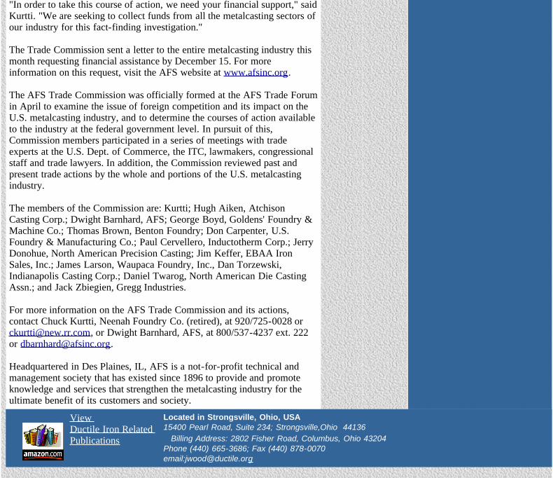
The Ductile Iron News - AFS Trade Commission
file:///C|/WEBSHARE/062013/magazine/2002_3/afstrade.htm[7/1/2013 9:23:25 AM]
"In order to take this course of action, we need your financial support," saidKurtti. "We are seeking to collect funds from all the metalcasting sectors ofour industry for this fact-finding investigation."
The Trade Commission sent a letter to the entire metalcasting industry thismonth requesting financial assistance by December 15. For moreinformation on this request, visit the AFS website at www.afsinc.org.
The AFS Trade Commission was officially formed at the AFS Trade Forumin April to examine the issue of foreign competition and its impact on theU.S. metalcasting industry, and to determine the courses of action availableto the industry at the federal government level. In pursuit of this,Commission members participated in a series of meetings with tradeexperts at the U.S. Dept. of Commerce, the ITC, lawmakers, congressionalstaff and trade lawyers. In addition, the Commission reviewed past andpresent trade actions by the whole and portions of the U.S. metalcastingindustry.
The members of the Commission are: Kurtti; Hugh Aiken, AtchisonCasting Corp.; Dwight Barnhard, AFS; George Boyd, Goldens' Foundry &Machine Co.; Thomas Brown, Benton Foundry; Don Carpenter, U.S.Foundry & Manufacturing Co.; Paul Cervellero, Inductotherm Corp.; JerryDonohue, North American Precision Casting; Jim Keffer, EBAA IronSales, Inc.; James Larson, Waupaca Foundry, Inc., Dan Torzewski,Indianapolis Casting Corp.; Daniel Twarog, North American Die CastingAssn.; and Jack Zbiegien, Gregg Industries.
For more information on the AFS Trade Commission and its actions,contact Chuck Kurtti, Neenah Foundry Co. (retired), at 920/725-0028 [email protected], or Dwight Barnhard, AFS, at 800/537-4237 ext. 222or [email protected].
Headquartered in Des Plaines, IL, AFS is a not-for-profit technical andmanagement society that has existed since 1896 to provide and promoteknowledge and services that strengthen the metalcasting industry for theultimate benefit of its customers and society.
View Ductile Iron Related Publications
Located in Strongsville, Ohio, USA15400 Pearl Road, Suite 234; Strongsville,Ohio 44136 Billing Address: 2802 Fisher Road, Columbus, Ohio 43204 Phone (440) 665-3686; Fax (440) 878-0070email:[email protected]

Ductile Iron News - News Briefs
file:///C|/WEBSHARE/062013/magazine/2002_3/nbriefs.htm[7/1/2013 9:23:43 AM]
To Promote the production and application of ductile iron castings Issue 3, 2002
News BriefsMEETINGS
Reseach Committee Meeting: January 15 and 16, 2003 at RamadaO'Hare, Rosemont, IL (Chicago Area). Tower rooms requested.
The June 2003 meeting will be held at The Woodlands Inn andResort in Wilkes Barre, Pennsylvania on June 2-4, 2003.
There will be a Keith Millis Symposium on October 20-23, 2003 atthe Crowne Plaza Resort in Hilton Head Island, South Carolina.
BUSINESS
Columbus, Ohio (USA) - Ashland Specialty Chemical Company'sFoundry Products Division announced today the creation of two newglobal business units, a new name for its overall business, and a newlogo.
"For over a century, we've been a leading supplier of binders andconsumables to the sand casting market," says Mike Swartzlander,vice president and general manager of the newly christened AshlandCasting Solutions. "To deliver increased value to customers, we haveexpanded our strategic focus beyond sand binder products to theentire metal casting process and new metal casting technologies. We've reorganized and renamed our business in line with our newidentity."
Two Global Business UnitsTo better focus human and materials resources against customerchallenges in its expanding markets, Ashland Casting Solutions willbe organized into two global business units.
The newly created Foundry Binder Solutions business unit willfocus on Ashland's sand binder product lines and services and buildon the company's worldwide technical leadership in cold box andbinder systems. Greg MacIver has been named business director ofFoundry Binder Solutions.
In addition, a Metal Casting Specialties business unit willconcentrate on the nonbinder metal casting consumables business. This organization will be responsible for existing refractory coatings,sand additives, core adhesives, releases, sleeves and filter lines aswell as for leveraging Ashland's technological expertise into othercasting areas such as lost foam, permanent mold, high pressure die,and investment casting. Philip Lipianka has been named director ofMetal Casting Specialties.
"I'm confident that these more focused business units will yield bothoperational and product benefits for customers," adds Swartzlander. "In most cases, the organizational changes will also be transparent tocurrent customers. They will continue to be served by the same
FEATURES
•Cover Story - Ductile Iron Societyreceives the Society/Association ofthe Year Award - See Photos
• Surface Defects in Iron Castings
• Applications of ADI
• Opportunities in Metal Casting
• FEF College Industry Conference
• Spectrometer Standards
• AFS Trade Commission
DEPARTMENTS
• News Briefs
• Advertisers
• Back Issues
• DIS Home Page
Ductile Iron News - News Briefs
file:///C|/WEBSHARE/062013/magazine/2002_3/nbriefs.htm[7/1/2013 9:23:43 AM]
salespeople and customer service representatives."
New Casting Solutions Name and Company Logo ComplementStructural Changes
The organizational realignment and name change to Casting Solutionscoincides with the launch of a new, more contemporary and dynamiclogo for all of Ashland Specialty Chemical Company.
About Ashland
Ashland Casting Solutions, a business unit of Ashland SpecialtyChemical Company, is a leader in supplying products, processes andtechnologies to the global marketplace for cold box sand bindersystems and non-binder metal casting systems.
Ashland Specialty Chemical Company, a division of Ashland Inc., isa leading, worldwide supplier of specialty chemicals servingindustries including adhesives, automotive, composites, foundry,merchant marine, paint, paper, plastics, semiconductor, watercraft andwater treatment. Visit the website www.ashspec.com to learn moreabout these operations.
Ashland, Inc. is a Fortune 500 company providing products, services,and customer solutions throughout the world. Our businesses includeroad construction, specialty chemicals, lubricants, car-care products,chemical and plastics distribution and transportation fuels. Throughthe dedication of our employees, we are "The Who in How ThingsWork.TM" Find us at www.ashland.com.
PEOPLE
Milwaukee, Wisconsin - Grede Foundries, Inc., has named thefollowing individuals as Vice Presidents: Tam Trudeau-Ebenhoehfor the Vassar foundry in Vassar, Michigan, Jeff Friday for theLiberty foundry in Milwaukee, Wisconsin, and Dave Roycraft forthe New Castle foundry in New Castle, Indiana.
Trudeau-Ebenhoeh joined Grede in 1991 at its Vassar foundry. Mostrecently, she served as Works Manager of the Vassar foundry.
Friday joined Grede in 1992 at its Reedsburg foundry in Reedsburg,Wisconsin. Most recently, he served as Works Manager at its Libertyfoundry.
Roycraft joined Grede in 1999 also at its New Castle foundry asFactory Manager and became Works Manager in November, 1999.
Grede Foundries operates foundries in the U.S. and the U.K., and is arecognized leading producer of high quality castings in gray iron,ductile iron, and steel.
TROY, Mich., December 11, 2002 - INTERMET Corporationannounced today that its Board of Directors elected Dr. Gary F.Ruff as President and Chief Operating Officer (COO) of theCorporation.
Dr. Ruff most recently was Executive Vice President and a memberof the Company's Operating Committee.
Ductile Iron News - News Briefs
file:///C|/WEBSHARE/062013/magazine/2002_3/nbriefs.htm[7/1/2013 9:23:43 AM]
Chairman and CEO John Doddridge also announced that it is hisintention to step down as Chief Executive Officer of the Company inJuly 2003, but remain as Chairman of the Board. Mr. Doddridge waselected Chairman and Chief Executive Officer of the Company inOctober 1994.
TROY, Mich., December 16, 2002 - INTERMET Corporationannounced that effective today, Thomas E. Prucha has beenpromoted to the position of Vice President, Technical Services, fromDirector, Process Research & Development. He reports to Dr. GaryF. Ruff, who recently was named President and COO ofINTERMET. In addition, Prucha will be a member of the CorporateOperating Committee.
Prucha's new responsibilities include oversight of INTERMET'sresearch and development, materials, process and product engineeringand development, environmental activities, and facilities engineering.
Back to top
View Ductile Iron Related Publications
Located in Strongsville, Ohio, USA15400 Pearl Road, Suite 234; Strongsville,Ohio 44136 Billing Address: 2802 Fisher Road, Columbus, Ohio 43204 Phone (440) 665-3686; Fax (440) 878-0070email:[email protected]