feasibility study report carbon dioxide capture · feasibility study report carbon dioxide capture...
TRANSCRIPT
Feasibility Study Report
CARBON DIOXIDE CAPTURE
to the Global CCS Institute
PUBLIC REPORT
GETICA CCS DEMO PROJECT
Romania
- December 2011 -

This page left blank intentionally
Financial and Institutional Support
Project Company
Technical Consortium
Global CCS Institute Australia
Institute for Studies and Power Engineering
Romania
Alstom Carbon Capture Germany
The National Gas Transmission Company „Transgaz” S.A Medias
Romania
The National Natural Gas Company „Romgaz” S.A Medias
Romania
Ministry of Economy, Trade and the Business Environment
Romania
Turceni Energy Complex Romania
December 2011 Feasibility Study
Carbon Dioxide Capture Getica CCS Demo Project
PUBLIC REPORT
Disclaimer
This report has been prepared by the Institute for Studies and Power Engineering and project partners for the exclusive use of The Global CCS Institute. It is subject to and issued in accordance with the agreement between The Global CCS Institute and ISPE.
Neither ISPE nor its project collaborators accept liability or responsibility whatsoever for it in respect of any use of or reliance upon this report by any third party.
This document is published on the Global CCS Institute's website in the interest of
information exchange. The Global CCS Institute does not give any representation or warranty as to the reliability, accuracy or completeness of the information, nor does it accept any responsibility arising in any way (including by negligence) for errors in, or
omissions from, the information.
©Global Carbon Capture and Storage Institute Limited 2011 Canberra. Use of this document is permitted in accordance with Creative Commons Attribution 3.0 Australia
License.

5
December 2011 Feasibility Study
Carbon Dioxide Capture Getica CCS Demo Project
PUBLIC REPORT
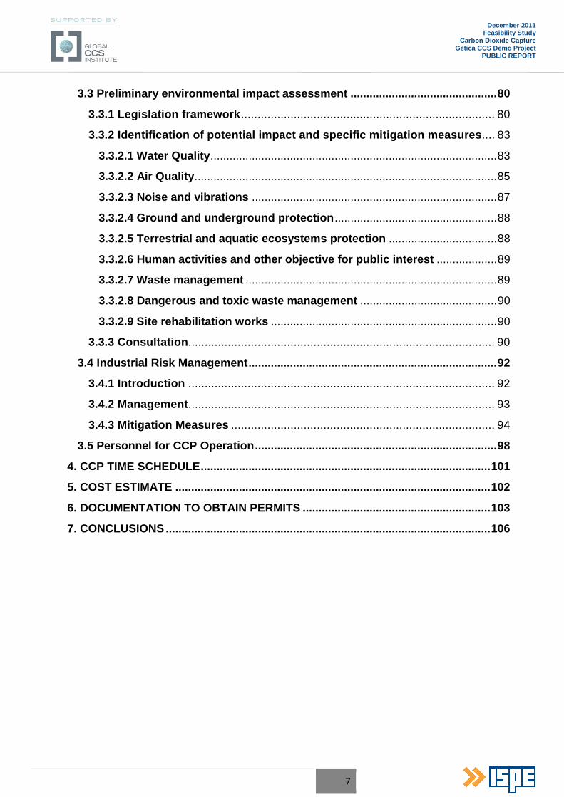
Content Page
GLOSSARY .................................................................................................................... 9
EXECUTIVE SUMMARY ............................................................................................... 11
1. GENERAL DATA ...................................................................................................... 17
1.1 Project name ....................................................................................................... 17
1.2 Project location .................................................................................................. 17
1.2.1 Area and location .................................................................................... 17
1.2.2 Legal status of the land to be occupied ................................................. 18
1.2.3 Land geo-physical characteristics ......................................................... 18
1.2.3.1 Nature of foundation soil ..................................................................... 18
1.2.3.2 Hydrogeological characteristics ......................................................... 19
1.2.4 Seismic conditions .................................................................................. 19
1.2.4.1 Characteristics on seismic zone .......................................................... 19
1.2.4.2 Characteristics of wind action .............................................................. 19
1.2.4.3 Characteristics of snow action ............................................................. 19
1.2.4.4 Environmental conditions .................................................................... 20
2. PROJECT GENERAL CONCEPT ............................................................................. 22
2.1 Current state and information on the entity responsible for project implementation ........................................................................................................ 22
2.1.1 Information on the entity responsible for project implementation ....... 22
2.1.2 Current state ............................................................................................ 23
2.2 Project objectives .............................................................................................. 25
2.3 Project general description .............................................................................. 25
2.4 CO2 Capture Technologies Options ................................................................. 28
2.4.1 Comparative analysis of CO 2 Capture Technologies options ............... 29
2.4.2 Chilled Ammonia Process (CAP) features and project references ....... 32
3. PROJECT TECHNICAL DATA ................................................................................. 37
3.1 Carbon Dioxide Capture Plant (CCP) ................................................................ 37
3.1.1 Basis of Design for CCP .......................................................................... 39
3.1.2 Chilled Ammonia Process (CAP) Description ........................................ 40
6
December 2011 Feasibility Study
Carbon Dioxide Capture Getica CCS Demo Project
PUBLIC REPORT
3.1.3 Block Flow Diagram and Heat and Mass Balance for the CCP ............. 51
3.1.4 Utilities consumption of the CCP ........................................................... 51
3.1.5 Chemicals consumption of the CCP ....................................................... 52
3.1.6 Plant effluent data ................................................................................... 52
3.1.7 Wastes from CCP ..................................................................................... 53
3.1.8 Process equipment list ............................................................................ 54
3.1.9 Estimated CCP Performances at Design Conditions ............................ 55
3.1.10 Special operating conditions ................................................................ 55
3.1.10.1 Transients during load changes ......................................................... 55
3.1.10.2 Abnormal and special operating procedures .................................... 55
3.1.10.3 Restart after emergency shutdown .................................................... 56
3.1.11 Regular maintenance ............................................................................. 57
3.1.12 Rotating equipment engineering .......................................................... 58
3.1.12.1 CO2 compression concept .................................................................. 58
3.1.12.2 CO2 Compressor selection ................................................................. 58
3.1.12.3 CO2 Pumping concept ......................................................................... 60
3.1.12.4 Compressors for the refrigeration system ........................................ 60
3.1.12.5 Back Pressure Turbine and Generator .............................................. 61
3.1.12.6 Expansion Turbines Types ................................................................. 61
3.1.13 CCP Layout ............................................................................................ 62
3.1.14 Electrical and Instrumentation engineering for CCP ........................... 63
3.2 Integration of the Carbon Dioxide Capture Plant intoTurceni PP .................. 65
3.2.1 Flue Gases Supply ................................................................................... 66
3.2.2 Process Steam interfacing for CCP ........................................................ 66
3.2.3 Steam extraction and condensate Tie-in Concepts ............................... 74
3.2.4 Cooling Water Integration ....................................................................... 75
3.2.5 Works for CCP integration within the power plant ................................ 77
3.2.5.1 Thermo-mechanical works .................................................................... 77
3.2.5.2 Make-up Water ....................................................................................... 78
3.2.5.3 Electric Works ........................................................................................ 78
3.2.5.4 Control system ....................................................................................... 79
3.2.5.5 Drinking Water, Fire fighting Water Supply and Sewage Systems ... 79
7
December 2011 Feasibility Study
Carbon Dioxide Capture Getica CCS Demo Project
PUBLIC REPORT
3.3 Preliminary environmental impact assessment .............................................. 80
3.3.1 Legislation framework ............................................................................. 80
3.3.2 Identification of potential impact and specific mitigation measures .... 83
3.3.2.1 Water Quality .......................................................................................... 83
3.3.2.2 Air Quality ............................................................................................... 85
3.3.2.3 Noise and vibrations ............................................................................. 87
3.3.2.4 Ground and underground protection ................................................... 88
3.3.2.5 Terrestrial and aquatic ecosystems protection .................................. 88
3.3.2.6 Human activities and other objective for public interest ................... 89
3.3.2.7 Waste management ............................................................................... 89
3.3.2.8 Dangerous and toxic waste management ........................................... 90
3.3.2.9 Site rehabilitation works ....................................................................... 90
3.3.3 Consultation ............................................................................................. 90
3.4 Industrial Risk Management .............................................................................. 92
3.4.1 Introduction ............................................................................................. 92
3.4.2 Management ............................................................................................. 93
3.4.3 Mitigation Measures ................................................................................ 94
3.5 Personnel for CCP Operation ............................................................................ 98
4. CCP TIME SCHEDULE ........................................................................................... 101
5. COST ESTIMATE ................................................................................................... 102
6. DOCUMENTATION TO OBTAIN PERMITS ........................................................... 103
7. CONCLUSIONS ...................................................................................................... 106
8
December 2011 Feasibility Study
Carbon Dioxide Capture Getica CCS Demo Project
PUBLIC REPORT
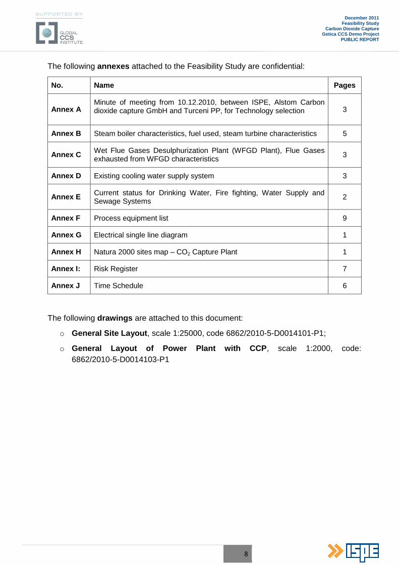
The following annexes attached to the Feasibility Study are confidential:
No. Name Pages
Annex A Minute of meeting from 10.12.2010, between ISPE, Alstom Carbon dioxide capture GmbH and Turceni PP, for Technology selection 3
Annex B Steam boiler characteristics, fuel used, steam turbine characteristics 5
Annex C Wet Flue Gases Desulphurization Plant (WFGD Plant), Flue Gases exhausted from WFGD characteristics 3
Annex D Existing cooling water supply system 3
Annex E Current status for Drinking Water, Fire fighting, Water Supply and Sewage Systems 2
Annex F Process equipment list 9
Annex G Electrical single line diagram 1
Annex H Natura 2000 sites map – CO2 Capture Plant 1
Annex I: Risk Register 7
Annex J Time Schedule 6
The following drawings are attached to this document:
o General Site Layout , scale 1:25000, code 6862/2010-5-D0014101-P1;
o General Layout of Power Plant with CCP , scale 1:2000, code: 6862/2010-5-D0014103-P1
9
December 2011 Feasibility Study
Carbon Dioxide Capture Getica CCS Demo Project
PUBLIC REPORT
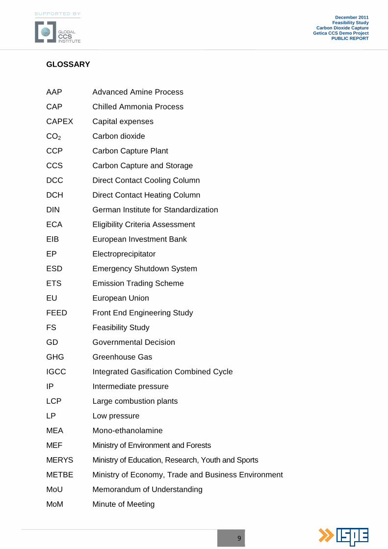
GLOSSARY
AAP Advanced Amine Process
CAP Chilled Ammonia Process
CAPEX Capital expenses
CO2 Carbon dioxide
CCP Carbon Capture Plant
CCS Carbon Capture and Storage
DCC Direct Contact Cooling Column
DCH Direct Contact Heating Column
DIN German Institute for Standardization
ECA Eligibility Criteria Assessment
EIB European Investment Bank
EP Electroprecipitator
ESD Emergency Shutdown System
ETS Emission Trading Scheme
EU European Union
FEED Front End Engineering Study
FS Feasibility Study
GD Governmental Decision
GHG Greenhouse Gas
IGCC Integrated Gasification Combined Cycle
IP Intermediate pressure
LCP Large combustion plants
LP Low pressure
MEA Mono-ethanolamine
MEF Ministry of Environment and Forests
MERYS Ministry of Education, Research, Youth and Sports
METBE Ministry of Economy, Trade and Business Environment
MoU Memorandum of Understanding
MoM Minute of Meeting
10
December 2011 Feasibility Study
Carbon Dioxide Capture Getica CCS Demo Project
PUBLIC REPORT
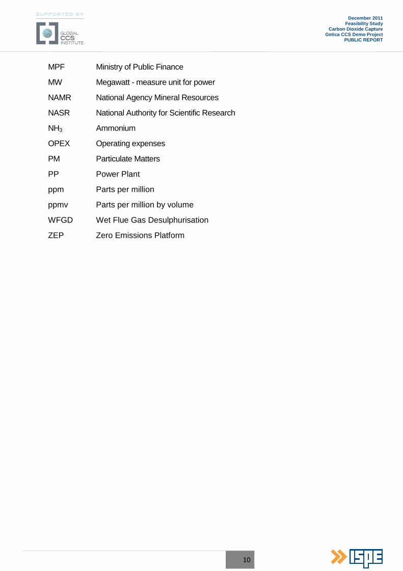
MPF Ministry of Public Finance
MW Megawatt - measure unit for power
NAMR National Agency Mineral Resources
NASR National Authority for Scientific Research
NH3 Ammonium
OPEX Operating expenses
PM Particulate Matters
PP Power Plant
ppm Parts per million
ppmv Parts per million by volume
WFGD Wet Flue Gas Desulphurisation
ZEP Zero Emissions Platform
11
December 2011 Feasibility Study
Carbon Dioxide Capture Getica CCS Demo Project
PUBLIC REPORT
EXECUTIVE SUMMARY
The Romanian CCS demo project, Getica CCS, is an integrated CCS project , comprising the full CCS chain: capture, transport and storage of carbon dioxide (CO2).
The investment authority (and final client of the entire CCS chain) is represented by a new Project Company (PC) , set up especially for this purpose. The company is new, but, in fact, the shareholders of the company are three existing companies, owned by the Romanian state as the majority shareholder, with large experience in power generation and, oil and gas:
• CE Turceni SA, an electricity generation company;
• SNTGN Transgaz SA, a natural gas transportation company;
• SNGN Romgaz SA, a natural gas extraction/storage company;
each of the companies covering one aspect of the project based on their expertise, namely CO2 capture, transport and storage.
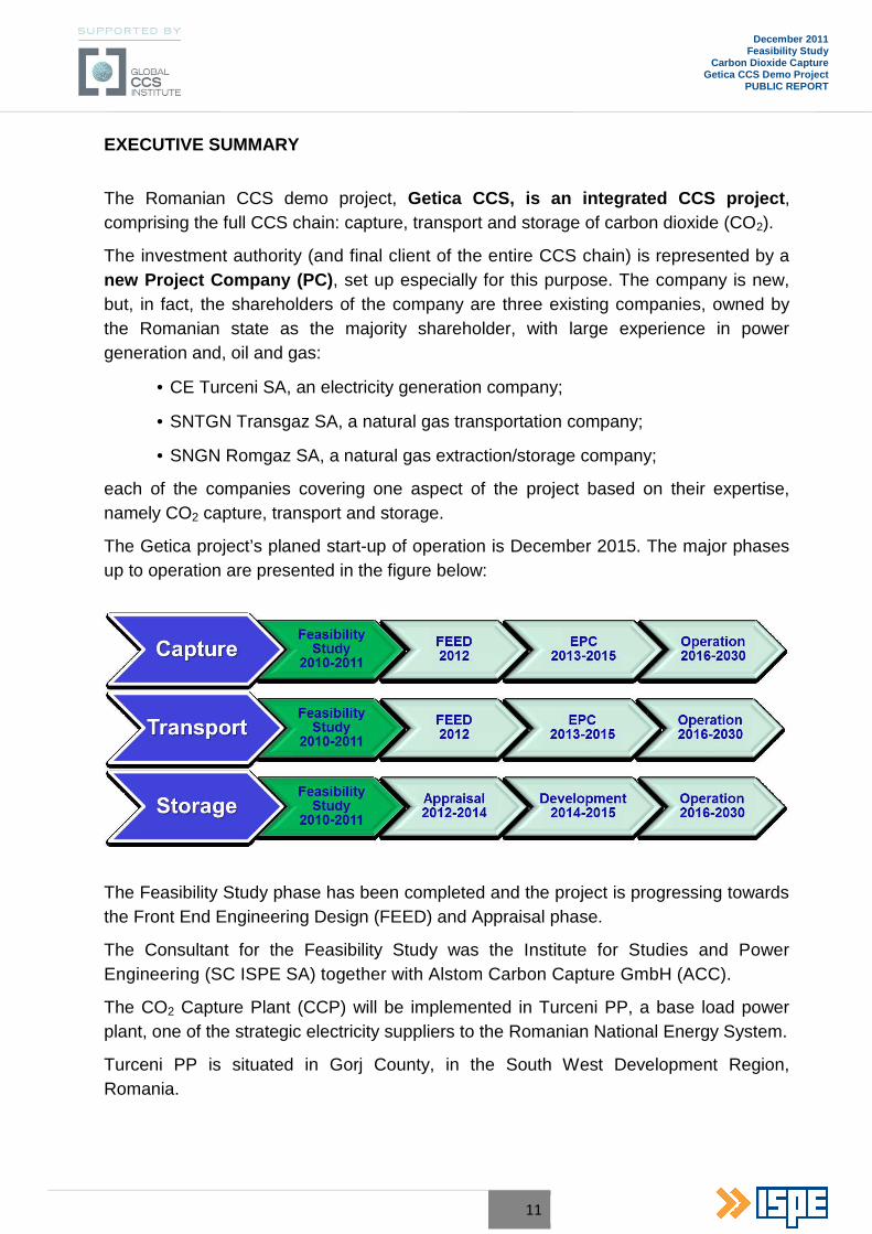
The Getica project’s planed start-up of operation is December 2015. The major phases up to operation are presented in the figure below:
The Feasibility Study phase has been completed and the project is progressing towards the Front End Engineering Design (FEED) and Appraisal phase.
The Consultant for the Feasibility Study was the Institute for Studies and Power Engineering (SC ISPE SA) together with Alstom Carbon Capture GmbH (ACC).
The CO2 Capture Plant (CCP) will be implemented in Turceni PP, a base load power plant, one of the strategic electricity suppliers to the Romanian National Energy System.
Turceni PP is situated in Gorj County, in the South West Development Region, Romania.
12
December 2011 Feasibility Study
Carbon Dioxide Capture Getica CCS Demo Project
PUBLIC REPORT
The CO2 Capture Plant will be fitted to one of the existing six units in Turceni PP, namely to the Unit no. 6 of 330 MW.
Power Unit no. 6 is an existing one, fuelled by local lignite, and it will be retrofitted and also equipped with Wet Flue Gases Desulphurization plant and dense slurry installation for ash and slag discharge.
The CCP will treat an equivalent flue gases flow of 250 MWe of gross electrical output (before capture) from Power Unit no. 6 WFGD exhaust. This project, when operational, will have a CO2 capture rate of more than 85% from the flue gases flow.
The optimum technology choice on post-combustion CO2 capture technologies was tailored to the specifics of the Unit no. 6 (project site, technological boundary conditions and integration possibilities). For the Getica CCS Demo Project, the selection was concentrated on the Chilled Ammonia Process (CAP) and the Advanced Amine Process (AAP), as they are the post-combustion CO2 capture technologies furthest in development and closest to commercialization.
CAP: Alstom conducts a comprehensive and intense Research and Development (R&D) program to develop the Chilled Ammonia Process (CAP), which is a very promising technology, encompassing a high degree of innovation and performance potential. CAP is based on the use of ammoniated aqueous solutions at temperatures below ambient. The CO2 is recovered in a highly concentrated and high-pressure form.
The advantages of ammoniated solution as CO2 absorbent include
• Low heat of reaction;
• High load of CO2;
• High pressure regeneration;
• Low sensitivity to impurities;
• Low cost of absorbent.
AAP: Alstom and the Dow Chemical Company have engaged in an exclusive partnership for the joint development and commercialization of the Advanced Amine Process (AAP) for CO2 capture from flue gases. Efforts have been made in two directions, namely in improving amine solution formulation and performance (Dow scope) and process improvement (Alstom scope). The joint development program ensures that the core competences of each of the participating companies are utilized to the fullest extent.
The advantages of the AAP compared to conventional MEA scrubbing include:
• More energy efficient capture of CO2;
13
December 2011 Feasibility Study
Carbon Dioxide Capture Getica CCS Demo Project
PUBLIC REPORT
• Lower solvent degradation rates, leading to lower chemical consumption and lower production of effluents and waste;
• Lower corrosivity, leading to less costly plants;
• Advanced and more flexible schemes, providing potential for the further energy savings.
For the specific operating condition of Unit no. 6, a CO2 Carbon Capture Plant based on the absorption of the CO2 from the flue gases was selected, using Alstom’s Chilled Ammonia Process (CAP). The Chilled Ammonia Process is a new technology with encouraging prospects regarding performance and emissions based on extensive laboratory and pilot testing. The process uses an ammoniated aqueous carbonate solution to absorb CO2 from the flue gases at ambient pressure and low temperature. Ammonia is a common, widely used and low cost chemical, readily available on the market from multiple sources.
The ammonia reagent in the CAP plant lends itself to fewer permitting requirements, including any waste disposal issues that may arise.
An extensive validation program for CAP is done, involving multiple projects of varying size to develop, validate and demonstrate the technology for power plant applications.
Ammonia is an energy-efficient reagent for regeneration from the capture of CO2. Ammonia is not susceptible to contamination of the flue gases and will be replenished in low consumption rates, as it will exhibit a very low (ppm level) and controllable loss in the CAP process.
From the standpoint of plant operations, the chilled ammonia process has demonstrated stable operation at turndown conditions. The CAP offers the flexibility and ability to follow daily and weekly changes in plant load requirements without impact on the process.
The flue gases from a typical WFGD system can be delivered to the CAP without any additional treatment facilities.
The compression and conditioning unit are designed to process 85% of wet CO2 gas from the regenerator to meet a pressure of 120 bar(a) and a temperature 30÷40°C. The CO2 purity will be more than 99.7% and with a water content less than 50 ppmv.
The treated flue gases stream will be exhausted into the atmosphere by a new stack, on the top of the Direct Contact Heater.
The by-product from the CAP facility is a liquid ammonium sulphate stream.
The ammonium sulphate can be used for sulphate based fertilizers, so it is a feedstock for chemical facilities. This opens opportunities for the by-product to be commercialized.
For this stage of the project, it was considered that the by-product will be given as it results from the process, without any conditioning, and with no price, to a possible user
14
December 2011 Feasibility Study
Carbon Dioxide Capture Getica CCS Demo Project
PUBLIC REPORT
of ammonium sulphate, from Romania (preferably) or from the international market, and the user will support the costs of transportation. For the next stages of the project (FEED), if the discussions and agreements with the potential local users or buyers of the by-product will be unsuccessful, a market analysis shall be conducted for the European Community market.
The CCP interfaces directly with various systems of the Turceni PP, therefore, an integration approach to the project is of significant importance.
The heat integration between the Power Plant and the Carbon Capture Plant (including the compression stage) has been envisaged to the fullest extent, in order to reduce any additional external requirement and to ensure optimization of the capture process, leading to minimize the investment cost (CAPEX), operation and maintenance costs (OPEX).
Steam is required to provide heat for CCP reboilers, in order to desorb CO2 from the rich solution and for stripping of NH3 from process water.
The Chilled Ammonia Process requires steam at two different pressure levels, an intermediate pressure (IP) steam and a low pressure (LP) steam. The steam will be extracted from the power plant steam cycle and desuperheated to meet the process requirements.
IP-steam will be extracted from the hot reheat line and guided to a new auxiliary steam turbine generating electrical power. The exhaust steam of the auxiliary steam turbine is guided into the CCP where it will be desuperheated with condensate, before being fed to the regenerator reboiler.
LP-steam will be extracted from the crossover pipe between intermediate pressure turbine section (IP-turbine) exhaust and low pressure turbine section (LP-turbine) inlet.
The extracted LP-steam will be guided to the carbon capture plant where it will be desuperheated with condensate, before being fed to the regenerator preheater and strippers. A part of the stripper condensate is used for desuperheating of the extracted LP-steam.
The generated IP-steam condensate will be subcooled before being mixed with the LP-steam condensate. Subsequently, the steam condensates will be collected and pumped back to the main condenser hot well, via the condensate heat exchanger. The condensate heat exchanger will transfer the heat of the steam condensate into power plant main condensate system (substitution of extraction steam for LP-preheating) without any risk of condensate contamination.
The heat from the hot reboiler condensate will be used within the CCP for pre-heating of rich solution upstream of the regenerator and then routed back to the power plant, to allow heat recovery for the boiler feed water pre-heating step.
15
December 2011 Feasibility Study
Carbon Dioxide Capture Getica CCS Demo Project
PUBLIC REPORT
The existing cooling water system is at its limits, therefore no further cooling water capacity for the capture plant is available.
A new cooling tower is envisaged for providing the cooling duty required by the capture plant. In addition, an evaporative (air cooled) condenser is provided to reject the heat from the refrigeration system to ambient air. Due to the high evaporation losses in the cooling tower make up water is required, to balance the losses and to compensate the blow down rate. Make up water as clarified water, will be supplied from Turceni PP Water Treatment Plant.
Various equipment of the CCP requires electrical power supply which cannot be ensured from the existing equipment of Unit no. 6 (330 MW). Therefore new electrical equipment will be provided to supply power for the CCP electrical consumers.
During normal operation, the CCP will be powered from the Unit no.6 internal auxiliary services. The stand-by powering will be made from the general services.
Partially, the CCP power supply will be ensured by the generator of the new auxiliary back-pressure steam turbine.
A preliminary environmental assessment was performed in order to provide an early indication of the potential environmental effects and the suitable mitigation measures. The construction and operation of CCP shall accomplish all the requirements of national and EU environmental legislation.
Identification of hazards for CCP operation and a preliminary risk assessment was done taking into consideration all the technical aspects that can have an impact on performance, health and safety, environment, time schedule and finance of the project. The objective was to establish a Risk Register for the next phases of the project: FEED/EPC and operation.
The results of this preliminary risk assessment are not meant to be final and will be updated periodically as more data becomes available. It is essential to consider it as a dynamic process and to update it periodically to reflect the status of the project and its new data/changes. A more sensitive scale will be more relevant for the next stages of the project and a quantitative risk assessment may be required for some risks qualified as critical. To support the risk management activities and to ensure the traceability of the risks over the project lifecycle, the risk policy and risk register will have to be implemented in a collaborative risk-based reporting tool.
The estimation of the investment costs includes the capital expenditure (CAPEX) and operational costs (OPEX) for CCP and integration of this in Unit no. 6 of Turceni PP and a quota for public awareness, communication and knowledge sharing and owner’s costs.
16
December 2011 Feasibility Study
Carbon Dioxide Capture Getica CCS Demo Project
PUBLIC REPORT
The Project implementation will contribute to maintaining operational the power plants running on local lignite, which contributes to the security of supply, not only in Romania, but also in the region and Europe.
It also creates the possibility of extension of the CCS technology for all the power producers in the region (over 4,000 MW) on local lignite and other energy intensive industries (metallurgical, refinery, chemical, cement, etc).
The herein report is part of a set of reports for the Getica CCS Demo Project, all of which will be made public on the Global CCS Institute’s website. These reports are:
• Permitting Report (available) – describing the permitting process for CCS projects in Romania and the applicable legislation;
• Financial Scenarios Report (to be published) – presenting high level details for the investment and operation costs and also the funding sources for the Getica project;
• NER300 Application Summary Report (to be published) – the report provides an overview on the NER300 application documentation and its preparation for the Getica Project;
• Feasibility Study Report – Overview (to be published) – the general presentation of the full chain CCS project from Romania. It provides a complete technical overview on all three sub-systems of the Getica project: capture, transportation and storage;
• Final Report (to be published) – will include information on the status of the Project, next steps, conclusions and lessons learned from the Feasibility Study execution.
Considering the current due diligence phase of the NER300 competition and the fact that the Getica CCS Demo Project is one of the participants to the European program, the confidentiality level of the project related information is very high. Thus, the information included in the above mentioned reports is only high level.
Nevertheless, the Project is committed to further disseminate relevant information as part of its public engagement strategy, in addition to the potential future contractual obligations of the Project Company.
By its demonstration nature, one of the Project’s objectives is to contribute to the global development of CCS. This includes providing high value information to the worldwide CCS community.
17
December 2011 Feasibility Study
Carbon Dioxide Capture Getica CCS Demo Project
PUBLIC REPORT
1. GENERAL DATA
1.1 Project name
A CCS demo project is intended to be implemented in Romania, as the result of the national ranking process. The CCS demo project has governmental support, as well as the support of Global CCS Institute.
The name of the project is Getica CCS Demo Project .
1.2 Project location
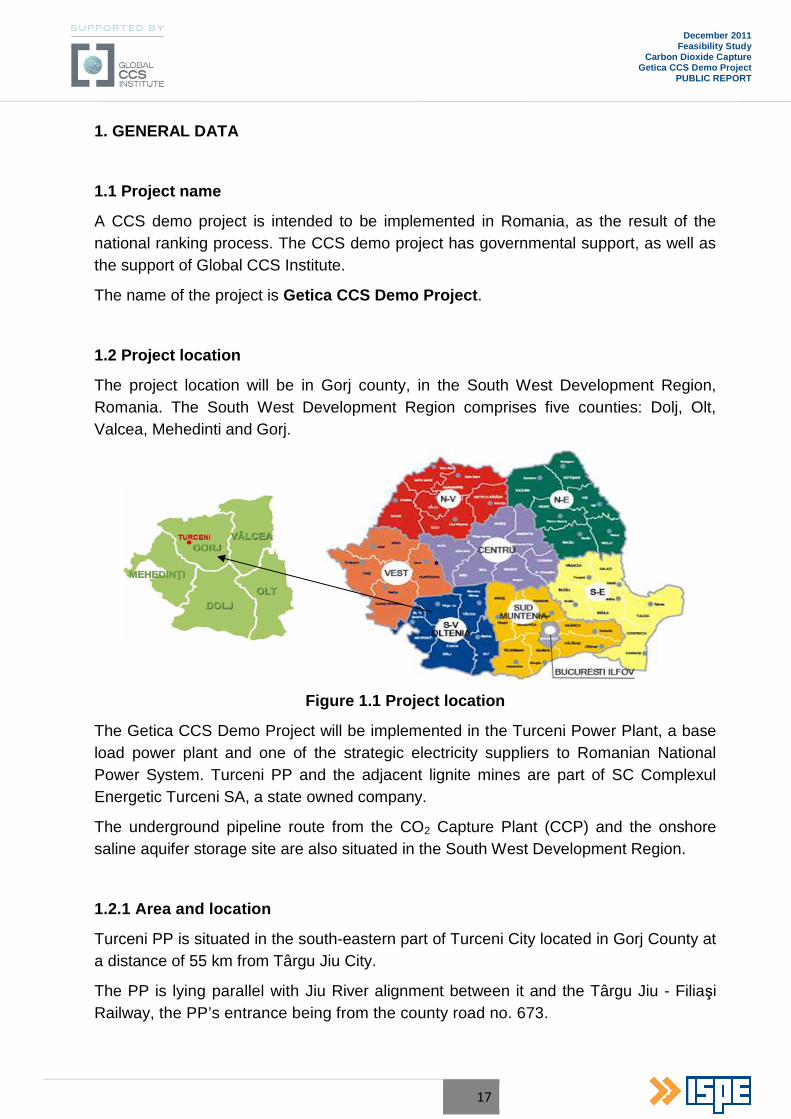
The project location will be in Gorj county, in the South West Development Region, Romania. The South West Development Region comprises five counties: Dolj, Olt, Valcea, Mehedinti and Gorj.
Figure 1.1 Project location
The Getica CCS Demo Project will be implemented in the Turceni Power Plant, a base load power plant and one of the strategic electricity suppliers to Romanian National Power System. Turceni PP and the adjacent lignite mines are part of SC Complexul Energetic Turceni SA, a state owned company.
The underground pipeline route from the CO2 Capture Plant (CCP) and the onshore saline aquifer storage site are also situated in the South West Development Region.
1.2.1 Area and location
Turceni PP is situated in the south-eastern part of Turceni City located in Gorj County at a distance of 55 km from Târgu Jiu City.
The PP is lying parallel with Jiu River alignment between it and the Târgu Jiu - Filiaşi Railway, the PP’s entrance being from the county road no. 673.
18
December 2011 Feasibility Study
Carbon Dioxide Capture Getica CCS Demo Project
PUBLIC REPORT
The coordinates of the location in both Geographical and 70 Stereo System are presented in Table 1.2.1 .
Table 1.2.1
Turceni PP geographical coordinates
System Coordinates
Geographical System latitudinal 44o 39` 54.56``
longitudinal 23o 24` 55.38``
70 Stereo System X 374449.658
Y 352945.973
1.2.2 Legal status of the land to be occupied
The CCP construction area is located within the Turceni PP premises, the land being the property of the Turceni Power Complex, located in Turceni City, 1st Uzinei Street.
Land indicators and urban indices
According to the Certificate of Property, the enclosed precincts of the Turceni PP lies on 1,598,521.34 m2. Coefficient POT and CUT of the power plant are:
• Coefficient of occupying land (POT) = 78%;
• Coefficient of using land (CUT) = 0.72.
After the new constructions to be located within CCP perimeter the new indicators POT and CUT of the power plant will be:
• Coefficient of occupying land proposed (POT) = 80%;
• Coefficient of using land proposed (CUT) = 0.75.
1.2.3 Land geo-physical characteristics
1.2.3.1 Nature of foundation soil
The location of Turceni TPP is on a lower terrace level of the Jiu River, whose deposit has an average thickness of 8 ÷ 10 m. In this area, all wells meet a thin layer of unconsolidated clays (layer A) 2 ÷ 3 m thickness, situated on the sandy gravel deposit (layer B) to a depth of 8 ÷ 9 m. Most of the time, between the layer of clay and sandy gravel deposit is intercalated with a layer of sand and clay, sometimes extending up to
19
December 2011 Feasibility Study
Carbon Dioxide Capture Getica CCS Demo Project
PUBLIC REPORT
4 ÷ 5 m deep. Terrace deposit is spread over the bedrock, consisting of sand and consolidated levantine clay.
The conventional pressure corresponding to the geotechnical study by the depth of 2.0 ÷ 3.0 m is Pconv = 200 ÷ 250 kPa, and by the depth of 8.0 ÷ 9.0 m is Pconv = 400 kPa.
The ground water level is at the depth of 5.50 m. from the ground level.
The freeze depth in site is 0.80 m, in accordance with STAS 6054/77.
1.2.3.2 Hydrogeological characteristics
The geotechnical studies revealed an aquifer with a free level, located at a depth of 5.55 m, in coarse gravel layer (drill no.1025, Unit no.6 area), with a coefficient filter KF = 60-100 l/day. Due to geological structure, on the impermeable manly clay layers water from infiltrations is collected, forming low water webs which appear daily as rare and weak springs. The major river bed is without water in dry periods, in contrast to rainy periods, when precipitation flow can be important.
1.2.4 Seismic conditions
1.2.4.1 Characteristics on seismic zone
According to the seismic map of Norm P100-1/2006, the site is located in the area of peak values of ground acceleration, for design ag = 0.16g, (with SMR = 100 years), and the control period (corner) Tc = 0.7 sec.
The maximum dynamic amplification factor of the horizontal ground acceleration from the structure in site is βo= 2.75, and the importance coefficient of the construction is γ=1.4 corresponding to the importance class I.
1.2.4.2 Characteristics of wind action
According to Norms NP-082-04, "Code for design due to the wind load", the characteristic wind speed in the TURCENI area is 35.0 m/s.
1.2.4.3 Characteristics of snow action
According to Norms CR 1-1-3-2005, "Code for design due to the snow load” the characteristic value of snow load is Sok = 2.0 kN/m2.

20
December 2011 Feasibility Study
Carbon Dioxide Capture Getica CCS Demo Project
PUBLIC REPORT
1.2.4.4 Environmental conditions
The high variation of the environmental conditions represents a fact that needs a rigorous analysis in the further stages of the project.
a. Air temperature
The air temperature in Degree Celsius, measured in the timescale of 90 years, between (1896÷1985), at the meteorological stations from the region is shown in the Table 1.2.4.4.1:
Table 1.2.4.4.1
Air temperature between 1896-1985)– monthly average
Station Alt. (m) I II III IV V VI VII VIII IX X XI XII
Târgu Jiu 210 -2.5 -0.4 4.9 10.8 15.8 19.4 21.6 20.7 16.9 11.0 4.9 -0.1
Strehaia 140 -2.9 -0.5 4.7 10.4 15.8 19.4 21.5 20.4 16.5 10.7 4.8 0.0
• The multi-annual average temperature is 10.20C at Târgu Jiu;
• The maximum amplitude multi-annual average: 23.50C (Târgu Jiu) and 24.40C (Strehaia);
• The monthly average temperature:
o -2.3 ÷ -2.90C, in January;
o +20.2 ÷ +21.60C, in July.
• The extreme temperatures in the region:
o -31.00C – absolute minimum temperature registered at 24.01.1942, in TârguJiu;
o -33.00C – absolute minimum temperature registered at 25.01.1907, in Strehaia;
o +40.60C – absolute maximum temperature registered at 8.09.1946, in Târgu Jiu;
o +43.50C – absolute maximum temperature registered at 20.08.1946, in Strehaia.
b. Air relative humidity
The air relative humidity analysed in the area has the annual average of 60 ÷ 70%, rising in the forest regions and on the slopes and Jiu River meadow to 75%. The maximum relative air humidity is registered in December and January, with 82 ÷ 75%, with the minimum registered in summer (July, August) with 62 ÷ 63%.

21
December 2011 Feasibility Study
Carbon Dioxide Capture Getica CCS Demo Project
PUBLIC REPORT
c. Rainfall and Snowfall
The measurements done in the past 10 years, in the hydrometric station Rovinari, show the rainfall and snowfall monthly averages. This information is presented in Table 1.2.4.4.2:
Table 1.2.4.4.2
Rainfall and Snowfall – monthly average (mm)
Hydrometric
Station I II III IV V VI VII VIII IX X XI XII
Rovinari 39.9 21.9 17.7 68.4 66.2 66.0 81.2 55.2 90.4 52.3 27.8 57.6
• The multi-annual average for rainfall quantity is 644.6 mm;
• The maximum rainfall during one year is registered in July and September, with 81÷90 mm;
• The minimum is registered in March, with 18 mm;
• Maximum 24 hour rainfall was 89 ÷ 95 mm;
• The average days with snow is 25 ÷ 40 days/year, with the snow lasting period being 40 ÷ 70 days/year.
22
December 2011 Feasibility Study
Carbon Dioxide Capture Getica CCS Demo Project
PUBLIC REPORT
2. PROJECT GENERAL CONCEPT
2.1 Current state and information on the entity responsible for project implementation
2.1.1 Information on the entity responsible for project implementation
The entity responsible for project implementation is the Project Company, consisting of three companies: Turceni Power Complex, Transgaz and Romgaz.
For the CCP project implementation the company responsible is Turceni Power Complex.
Turceni Power Complex was established as a company held by State on 1 April 2004 through the governmental decision no. 103/29 January 2004.
Turceni Power Complex holds the following facilities:
• Turceni Power Plant – 8 x 330 MWe gross output (design power output);
• Lignite mining sites Jilt South and North: commissioned in 1977, 6,500 thousands tons /year, industrial reserves of 285,800 thousands tons, lower heating value of 1,700 kcal/kg;
• Tehomir lignite mine: commissioned in 1978, 400 thousands tonnes/year, industrial reserves 1,520 thousands tons, lower heating value of 1900 kcal/kg.
• Mining equipment:
o 14 excavators ERC 1,400.30/7 type, 1,800 m3/h capacity;
o 104 belt conveyors meaning 62 km, with capacities between 4700 and 8000 m3/h;
o 8 stackers MH 4400x170 type and MH 6,500x90 type;
o 2 stacker/reclaimer combined machines, KS 5,600/3800 x 40 type.
The main investment done by Turceni Power Complex consisted of retrofitting (programme A3) for the power Unit no. 4 (commissioned in April 2002) and no. 5 (commissioned in April 2006) and the following environmental protection investments:
• Electrostatic precipitators were retrofitted for Units no. 1 to 7, therefore the dust emissions were reduced to 100 mg/Nm3 (50 mg/Nm3 for Unit no. 5);
• Units no. 3, 5 and 7 were fitted with a 0pollutant emissions monitoring system;
• Waterproofing the walls, monitoring wells borings and drainage system for Valea Ceplea ash pond;
• Cooling towers no. 3 and 6 retrofitting;

23
December 2011 Feasibility Study
Carbon Dioxide Capture Getica CCS Demo Project
PUBLIC REPORT
• Mounting of noise dampers for Units no. 4 and 5;
• On-going contracts and erection works for Wet Flue Gases Desulphurization plants for Units no. 3, 4, 5 and 6 in order to comply with the GD 440/2010;
• Erection works for dense slurry ash and slag exhaust system in order to comply with the GD 349/2005;
• 140 ha of land from the mining facilities were given back to the economy circuit as 100 ha for forestry and 40 ha for agricultural purposes;
• The coal storages from the mining facilities were surrounded by natural barrier created with locus tree;
• In the mining facilities in the area for coal loading in rail wagon were mounted aprons and humidifying equipment.
2.1.2 Current state
Turceni Power Plant is pulverised lignite fired power plant, based on a conventional steam cycle in condensation, and operates in the base load of the National Grid. Its eight power units were commissioned in 2 stages:
• Stage I – with a gross power output of 1,320 MWe, composed from no. 1÷4
power units, commissioned between 1978÷1982;
• Stage II – designed for 1,320 MWe gross power and composed from no. 5÷7 units commissioned between 1983÷1987 and no. 8 power unit which erection was stopped by governmental decision, GD no. 897/2002.
The current situation of the power units (the commissioning year between brackets) is the following:
• Power Unit no. 1 (1978): in operation;
• Power Unit no. 2 (1979): out of service, decommissioning started;
• Power Unit no. 3 (1980): in operation;
• Power Unit no. 4 (1981): in operation, retrofitted by A3 Programme (2002);
• Power Unit no. 5 (1983): in operation, retrofitted by A3 Programme (2006);
• Power Unit no. 6 (1985): conserved, to be retrofitted;
• Power Unit no. 7 (1987): in operation;
• Power Unit no. 8 (unfinished): decommissioned;
Turceni PP’s units have the following general characteristics:
• Fuel:
24
December 2011 Feasibility Study
Carbon Dioxide Capture Getica CCS Demo Project
PUBLIC REPORT
o Lignite 70% from Turceni Power Complex mining facilities and 30% from other mines, 500000 t stored in PP, supplied by train;
o Fuel oil for boilers start-up;
o Petroleum gas as flame support, extracted from Ţicleni-Bibeşti-Turburea.
• Boilers:
o 1,035 t/h superheated steam boilers;
o With reheating;
o Steam parameters: 540 0C and 196 ata;
o Tower type, build by Vulcan Romanian company under a Babcock licence.
• Steam turbines:
o 330 MWe Condensation type;
o 4 turbine sections single shafted;
o Built by IMGB Romanian company under Rateau-Schneider licence.
• Electrical generators:
o 330 MWe, 50 Hz;
o Hydrogen cooled;
o Built under Alstom licence.
• Power transformers (for National Grid connection):
o 1 piece/unit, 24/400 kV, 400 MVA.
• National Grid connection:
o 4 lines of 400 kV (2 units per line), connected in a substation close to Ţânţăreni village, at about 9.0 km.
• Cooling:
o 7 natural draft counter-current cooling towers, 42,000 m3/h each;
o Closed circuit with 0.75 m3/s/unit of makeup water from Jiu River;
o Semi-closed circuit with 12.0 m3/s/unit of water flow from Jiu River.
• Ash and slag (hydraulic exhaust):
o 1st ash pond: Valea Ceplea with a capacity of 2.0 million m3, located at about 3.5 km from PP’s site;
o 2nd ash pond: back-up of 6.0 million m3.
25
December 2011 Feasibility Study
Carbon Dioxide Capture Getica CCS Demo Project
PUBLIC REPORT
2.2 Project objectives
The project will capture the CO2 equivalent of 250 MWe gross power output from 330 MWe nominal gross power output, of the power Unit no. 6 from Turceni PP, without CCS applied.
The main objectives of the Carbon Dioxide Capture Feasibility Study for the Getica CCS Demo Project are as follows:
• To determine the appropriate available technology to be used for the Carbon Dioxide Capture and to develop the optimized thermal integration of the CCP into the power plant with resulting performance profile of the power plant;
• To provide an overall material balance showing the mass flow rate for all feeds and products of the CCP;
• To define/estimate average and peak consumption and production figures for utilities needed to operate CCP, including the main electrical power consumers;
• To assess the existing available utilities at the power plant;
• To prepare a list of CCP equipment;
• To develop a CO2 compression concept taking into consideration the specific requirement of the site;
• To integrate the CCP equipment, including compression station into Turceni PP site;
• To estimate the total installed cost of CCP;
• To asses a preliminary environmental impact of the CCP;
• To describe the proceedings and documentation needed to obtain agreements, permits or authorizations for CO2 capture plant, and the authorities involved.
2.3 Project general description
The R&D in the CCS field has identified many technologies for CO2 capture, transport and storage, which are feasible and will be developed in the future, listed below:
• Carbon dioxide capture technologies:
o Pre-combustion;
o Oxy-fuel;
26
December 2011 Feasibility Study
Carbon Dioxide Capture Getica CCS Demo Project
PUBLIC REPORT
o Post-combustion:
� Classical post-combustion with mono-ethanolamine (MEA);
� Advanced Amine Process (AAP);
� Chilled Ammonia Process (CAP);
• CO2 transport technologies:
o Pipelines (onshore/offshore) – the CO2 is maintained in supercritical fluid phase at high pressure;
o Tanks on truck or boat – CO2 is maintained in liquid phase by refrigeration under -50 0C;
• CO2 storage technologies:
o In deep saline aquifers (porous underground geological layer, the gap between rocks being occupied by a very salted water) paced at least 2000 m in depth (onshore or under the sea bottom);
o Enhanced oil and gas recovery (the CO2 injected into the oil and gas sands replace the volume of the hydrocarbons forcing them to get more to the surface thus making them easier to be extracted).
Obviously, from the conception phase of the project a preliminary analysis of options was done based on the site and information already made public from the Research and Development (R&D).
Therefore without any options proposals to be analysed in an Options Analyse Study or Prefeasibility Study the following options were considered for the project, with the proper justification:
1. The CO2 capture technology will be post-combustion
The post-combustion technologies are conceived and designed to be easily implemented in existing power plants, being installed directly on the flue gases path after the existing installations for pollutant emissions reduction. These post-combustion technologies actually consist of extracting the CO2 from the flue gases stream generated by the power plant, using physically-chemical processes. Practically the flue gases are introduced in a cooler, then into an absorber where the reagent captures the most part of the CO2 from the flue gases. The cleaned flue gases are exhausted on top of the absorber. The reagent, which captured the CO2, is sent to the desorption column (stripper) where the chemical reactions are reversed and the CO2 is separated from the reagent. The CO2 is sent to compression and the reagent is sent back to the absorber for further CO2 capture. The absorption capacity of the reagent, the
27
December 2011 Feasibility Study
Carbon Dioxide Capture Getica CCS Demo Project
PUBLIC REPORT
energy needed for desorption are giving the overall performance of the post-combustion CO2 capture technology.
The pre-combustion technology implies a completely new power plant in which the fuel (lignite) is gasified, the syngas obtained is treated, steam reformed and cleaned of CO2, being afterwards burned in a combined cycle. For obvious reasons this technology is not feasible for power Unit no. 6 from Turceni PP which is based on the pulverized coal (PC) technology. Transforming Unit no. 6 into an Integrated Gasification Combined Cycle with Integrated CO2 Capture (IGCC) is technically almost impossible and the entire replacement of power Unit no. 6, for which the retrofitting contract is already signed, is not an economically feasible option.
In case of the oxy-fuel technology, which means the burning of the fuel in an O2/CO2 environment, the technological implications for the steam boiler (the rising of the furnace temperature needs flue gases recirculation, sealing off the entire flue gases path in order to minimize the air infiltrations etc.) are making the implementation of this technology very difficult for an existing high power steam boiler as the one from Turceni PP’s Unit no. 6.
On the other hand, the production of the oxygen needed in oxy-fuel is done by physically (cryogenically) separating the gaseous species from ambient air, into an Air Separation Unit (ASU), which is a high energy consumer. A deep integration of the ASU process with the PP’s steam cycle can lead to a satisfactory global net efficiency, but this is possible only in the case of a new designed power plant in this respect. In case of power Unit no. 6 from Turceni PP, because one ASU unit cannot supply the equivalent need of oxygen for 250 MWe, more than one ASU units were deemed necessary.
Therefore, no scaling effect for the ASU can be used in advantage of efficiency and no proper integration with an existing steam cycle is possible (as explained before). These two aspects lead to an increase of capital expenditures (CAPEX) and operational expenditures (OPEX) which makes this option to be less economically tempting. From the technological point of view, the implications which result from the retrofitting of the existing boiler for oxy-fuel lead this option to be on the limit of technical feasibility.
As previously shown, there are already three types of post-combustion technologies, based approximately on the same principle but in which the reagent or its characteristics are different. The advanced amine process is of course a later development of the classical post-combustion carbon dioxide capture with amine. In the case of the chilled ammonia process the reagent is ammonia carbonate in aqueous solution (prepared from ammonia), which is a more common reagent. The technological differences imposed by this technology
28
December 2011 Feasibility Study
Carbon Dioxide Capture Getica CCS Demo Project
PUBLIC REPORT
are linked with the low temperature on which most of the processes are taking place.
Because without a more rigorous analysis it cannot be appreciated which of the post-combustion CO2 capture technology is technically and economically feasible, in case of implementation in Unit no. 6 from Turceni PP, these two technologies were proposed as options for CO2 capture in an Options Analysis Study.
2. The CO2 transport will be done by pipeline
The technical solution for CO2 transport is almost always linked to the technical solution for CO2 storage. In this project, as it will be shown the storage is done in a deep saline aquifer from the region of Turceni PP from which the CO2 produced by power Unit no. 6 is captured. Therefore the storage is onshore and relatively close (at a maximum length of 50 km). The deep saline aquifer storage implies the injection of CO2 at a high pressure in supercritical fluid phase in order to occupy the smallest possible volume. In this situation the optimum transport technology is by pipeline, which is suitable for not very long distances (maximum 100 ÷ 200 km). In order to reduce the CO2 volume and therefore the pipeline diameter the CO2 is transported in supercritical phase, at a pressure higher than 90 bar(a), and at the exhaust of the carbon dioxide capture plant’s compression line the pressure being commonly between 110 ÷ 150 bar(a).
3. The CO2 storage will be done in a deep saline aquifer
The geological data from the region showed a potential for CO2 storage in deep saline aquifer and for enhanced hydrocarbons recovery.
Because this project is a demonstrative one and the research indicated a great CO2 deep saline aquifer storage potential for Europe, it is desired from this project to demonstrate this technological solution for storage on a demonstrative scale. Choosing this storage technology, which is in the interest of the entire European Commission, encourage the granting of a higher score during the selection of projects for NER 300 financing award.
2.4 CO2 Capture Technologies Options
As described previously, the technology for CO2 storage and transport is already fixed and in the case of CO2 capture the technology will be post-combustion. There are two different options to choose from: Advanced Amine Process (AAP) or Chilled Ammonia process (CAP).
Therefore, the two CO2 capture technologies options analysed are the following:
29
December 2011 Feasibility Study
Carbon Dioxide Capture Getica CCS Demo Project
PUBLIC REPORT
• Option 1: Advanced Amine Process (AAP)
Alstom and the Dow Chemical Company are engaged in an exclusive partnership for the joint development and commercialisation of the Advanced Amine Process (AAP) for CO2 capture from flue gas at ambient conditions. This partnership is set up to leverage the complementary core competencies and strength of each of the companies. Dow brings competence on optimising the amine formulation and performance of the proprietary solvent as well as its unique Heat Stable Salt Management System, UCARSEP electro dialysis process, both aiming to minimise effluents emissions, degradation and operating costs. Alstom brings the long experience of designing and building power and petrochemical plants and handling the physics of large flue gases flows. The proposed advanced flow scheme is based on the results of this partnership and utilises the 2nd generation of the AAP technology which brings lower specific energy consumption as compared to other amine processes.
• Option 2: Chilled Ammonia Process (CAP)
The Chilled Ammonia Process (CAP), a new technology with encouraging prospects regarding performance and emissions based on extensive laboratory and pilot testing. The process uses an ammoniated aqueous carbonate solution to absorb CO2 from the flue gas at ambient pressure.
As ammonia is a common and widely used chemical, the ammonia reagent in the CAP plant lends itself to fewer permitting requirements, including any waste disposal issues that may arise. The by-product from the CAP facility is a liquid ammonium sulphate stream, which can be of commercial value as a fertilizer. Optionally the ammonia is removed in a dedicated Ammonia Recovery Unit. In this case, the by-product is gypsum. Alstom is currently executing an extensive validation program involving multiple projects of varying size to develop, validate and demonstrate the technology for power plant applications.
2.4.1 Comparative analysis of CO 2 Capture Technologies options
The optimum technology choice on post combustion carbon capture technologies should be tailored to the specifics of the individual project. This on consideration of the project site, technological boundary conditions and integration specifics, but also setting the envisaged realization time schedule in relation to the degree of maturity of the technologies, which are in different stages of development and maturity.
Considering the time schedule of the Getica CCS demo project, the selection concentrates on Chilled Ammonia Process (CAP) and the Advanced Amine Process (AAP), as they are the technologies furthest in development and closest to commercialization.
30
December 2011 Feasibility Study
Carbon Dioxide Capture Getica CCS Demo Project
PUBLIC REPORT
CAP: Alstom conducts a comprehensive and intense R&D program to develop the Chilled Ammonia Process (CAP), which is a very promising technology, encompassing a high degree of innovation and performance potential. CAP is based on the use of ammoniated aqueous solutions at temperatures below ambient. The CO2 is recovered in a highly concentrated and high-pressure form.
The advantages of ammoniated solution as CO2 absorbent include:
• Low heat of reaction;
• High load of CO2;
• High pressure regeneration;
• Low sensitivity to impurities;
• Low cost of absorbent.
AAP: Alstom and The Dow Chemical Company have engaged in an exclusive partnership for the joint development and commercialization of the Advanced Amine Process (AAP) for CO2 capture from flue gases. Efforts have been made in two directions, namely in improving amine solution formulation and performance (Dow scope) and process improvement (Alstom scope): The joint development program ensures that the core competences of each of the participating companies are utilized to the fullest extent.
The advantages of the AAP compared to conventional MEA scrubbing include:
• More energy efficient capture of CO2;
• Lower solvent degradation rates, leading to lower chemical consumption and lower production of effluents and waste;
• Lower corrosivity, leading to less costly plants;
• Advanced and more flexible schemes, providing potential for further energy savings.
Investment Costs (CAPEX)
Compared to the AAP, the investment costs are higher for the CAP because of the technological differentiation, which results in more equipment.
This results in an advantage for the Advanced Amine Process.
Operation and Maintenance Costs (OPEX)
The operation costs for AAP are higher primarily due to the cost of the amine formula solution, compared to the commodity ammonia make-up for the CAP.
For the ammonia make-up supply, the existing supply-chain may be utilized. Romania has suitable ammonia production facilities available, which allow independent and “just-in-time” supply from domestic supply sources.
31
December 2011 Feasibility Study
Carbon Dioxide Capture Getica CCS Demo Project
PUBLIC REPORT
This is considered advantageous for the application of the Chilled Ammonia Process.
Energy Consumptions
The energy consumptions for CAP and AAP are comparable. However, there are differences between the forms in which the energy is used (steam, electric power or cooling water).
Solvent and Operation Experience
Ammonia is already used in CE Turceni for the normal operation of the Power Plant. This allows the utilization of the existing infrastructure for the Chilled Ammonia Process.
The operator of the Power Plant – CE Turceni – has long term experience with handling ammonia. Therefore additional training for the existing operational staff may be avoided.
This results in an advantage for the Chilled Ammonia Process.
Plot Requirements
The available plot space is suitable for both technologies.
Authority Permits
The existing CE Turceni has in place authority permits, which consider and permit the use of ammonia in the installed power plant. This fact will ease the application and permitting procedures for a Carbon Capture Plant, which uses the same chemical, being ammonia, and does not introduce a new type of chemical substance as solvent.
This results in an advantage for Chilled Ammonia Process.
EU Selection Criteria
Apart from the above facts, the selection of the Chilled Ammonia Process for the carbon capture application at the Unit no. 6 of CE Turceni adds a technology to the European CCS demonstration projects, which up to now is not considered. This could favourably influence the selection of the Getica CCS Demo Project for the NER 300 grant, by differentiation and diversification of the applied CCP technology in comparison to other applicants. One important criterion for being selected by the NER 300 competition is that “at least one project and at most three projects are selected in each category”.
This results in an advantage for Chilled Ammonia Process.
Evaluation Matrix
The following evaluation matrix summarizes the above conclusions by applying weighting factors and numeric scores for the technology assessment.
32
December 2011 Feasibility Study
Carbon Dioxide Capture Getica CCS Demo Project
PUBLIC REPORT
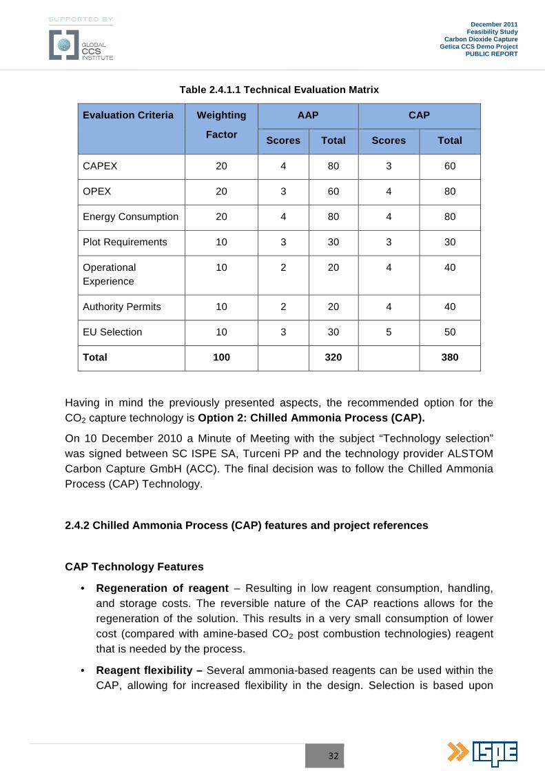
Table 2.4.1.1 Technical Evaluation Matrix
Evaluation Criteria Weighting
Factor
AAP CAP
Scores Total Scores Total
CAPEX 20 4 80 3 60
OPEX 20 3 60 4 80
Energy Consumption 20 4 80 4 80
Plot Requirements 10 3 30 3 30
Operational Experience
10 2 20 4 40
Authority Permits 10 2 20 4 40
EU Selection 10 3 30 5 50
Total 100 320 380
Having in mind the previously presented aspects, the recommended option for the CO2 capture technology is Option 2: Chilled Ammonia Process (CAP).
On 10 December 2010 a Minute of Meeting with the subject “Technology selection” was signed between SC ISPE SA, Turceni PP and the technology provider ALSTOM Carbon Capture GmbH (ACC). The final decision was to follow the Chilled Ammonia Process (CAP) Technology.
2.4.2 Chilled Ammonia Process (CAP) features and project references
CAP Technology Features
• Regeneration of reagent – Resulting in low reagent consumption, handling, and storage costs. The reversible nature of the CAP reactions allows for the regeneration of the solution. This results in a very small consumption of lower cost (compared with amine-based CO2 post combustion technologies) reagent that is needed by the process.
• Reagent flexibility – Several ammonia-based reagents can be used within the CAP, allowing for increased flexibility in the design. Selection is based upon
33
December 2011 Feasibility Study
Carbon Dioxide Capture Getica CCS Demo Project
PUBLIC REPORT
reagent availability, lifecycle cost, delivery, handling and storage preferences, and site permitting requirements;
• Commercial by-product – The by-product is an ammonium sulphate by-product stream that can be used commercially as fertilizer;
• Low energy consumption – The low heat of reaction and regeneration associated with the Chilled Ammonia Process will result in a low CO2 capture energy consumption. Operation of the CAP at lower process temperatures results in low emissions.
• CO2 product purity – Alstom’s Chilled Ammonia Process bench scale and pilot facilities have produced a high-purity (99.5+%) CO2 product stream containing low moisture and trace of ammonia at elevated pressure, resulting in reduced energy costs for compression.
• Flexible integration with steam cycle – The Chilled Ammonia Process is compatible for easy retrofit with the existing power generation facility and steam cycle – the steam source quality and pressure can be accommodated in the CAP. Alstom is uniquely qualified to assess the existing steam cycle components, to predict the power generation facility net generation with the CCS equipment in place and to successfully integrate the process into the power plant.
• Flue gases compatibility – The Chilled Ammonia Process is capable of processing flue gases, from typical Air Quality Control Systems, (AQCS) equipment, without the need for additional flue gases treatment as compared to many other post combustion technologies.
CAP Process – Project References
Based upon the promising results at the bench-scale level, Alstom embarked on a multi-phase development program. In the first step of this program, a large bench pilot was constructed and operated at SRI International from November 2006 through June 2008 to demonstrate both CO2 absorption and regeneration. The bench-scale regenerator demonstrated CO2 product stream quality of greater than 99.5%, with ammonia emissions below 10 ppm and water emissions well below 1000 ppm, without further treatment. The data from the bench scale pilot was used to develop an equilibrium and thermodynamic model of the process. This model was initially applied to size equipment for field validation pilots at WE Energies’ Pleasant Prairie Power Plant and E.ON Karlshamn.
CAP Field Pilots at We Energies and E.ON Karlshamn

34
December 2011 Feasibility Study
Carbon Dioxide Capture Getica CCS Demo Project
PUBLIC REPORT
Figure 2.4.2.1 Field Pilot at We Energy’s Pleasant Prairie Power Plant
The field pilot at We Energies illustrated in Figure 2.4.2.1 was sized to capture over 15,000 tonnes/year of CO2 at full capacity and commenced operations in June 2008. The pilot has been operating 24 hours per day, 7 days per week with continuous shifts since September 2008. This testing has resulted in a greatly improved understanding of the process and interactions with the power plant. While some modifications have been applied, no significant changes to the overall concept have proven necessary. The validation program was successfully finalized in October 2009. The following key criteria have been validated:
• Over 7,500 hours of operation;
• 90% CO2 removal;
• Proof of concept;
• Initial data on steam and electrical power consumption is consistent with expectations.
A second field pilot was commissioned at E.ON Karlshamn in April of 2009 to collect CO2 emissions from a boiler combusting a high sulphur fuel oil that has installed AQCS systems to control emissions of PM, SOx and NOx. The two field pilots were designed as ‘proof of concept’ facilities with considerable operating flexibility to test the different unit operations. Four of the key criteria to validate the chilled ammonia process were initially identified as follows (to be met at the design conditions):
• 90% CO2 removal;
• Low ammonia slip;
• High CO2 quality (with low ammonia slip and low moisture content);
• Low system pressure drop.
35
December 2011 Feasibility Study
Carbon Dioxide Capture Getica CCS Demo Project
PUBLIC REPORT
CAP Product Validation Facility at AEP’s Mountaineer Power Station
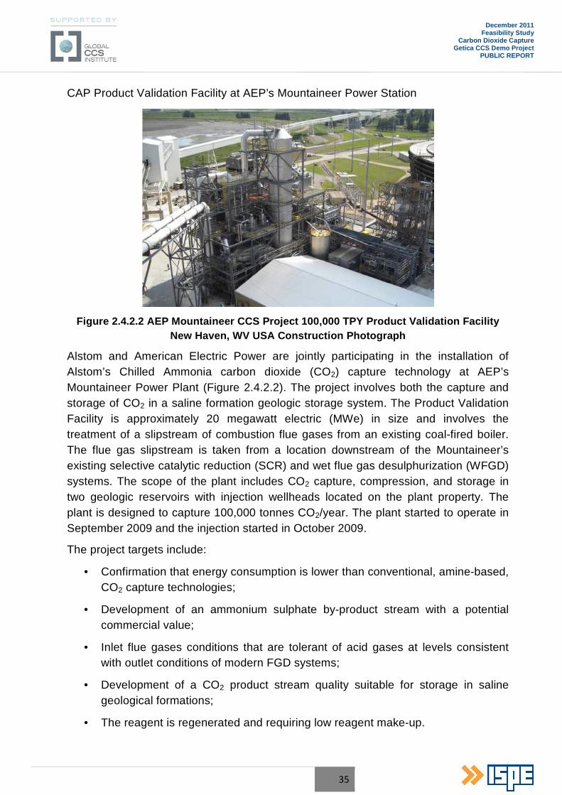
Figure 2.4.2.2 AEP Mountaineer CCS Project 100,000 TPY Product Validation Facility New Haven, WV USA Construction Photograph
Alstom and American Electric Power are jointly participating in the installation of Alstom’s Chilled Ammonia carbon dioxide (CO2) capture technology at AEP’s Mountaineer Power Plant (Figure 2.4.2.2). The project involves both the capture and storage of CO2 in a saline formation geologic storage system. The Product Validation Facility is approximately 20 megawatt electric (MWe) in size and involves the treatment of a slipstream of combustion flue gases from an existing coal-fired boiler. The flue gas slipstream is taken from a location downstream of the Mountaineer’s existing selective catalytic reduction (SCR) and wet flue gas desulphurization (WFGD) systems. The scope of the plant includes CO2 capture, compression, and storage in two geologic reservoirs with injection wellheads located on the plant property. The plant is designed to capture 100,000 tonnes CO2/year. The plant started to operate in September 2009 and the injection started in October 2009.
The project targets include:
• Confirmation that energy consumption is lower than conventional, amine-based, CO2 capture technologies;
• Development of an ammonium sulphate by-product stream with a potential commercial value;
• Inlet flue gases conditions that are tolerant of acid gases at levels consistent with outlet conditions of modern FGD systems;
• Development of a CO2 product stream quality suitable for storage in saline geological formations;
• The reagent is regenerated and requiring low reagent make-up.
36
December 2011 Feasibility Study
Carbon Dioxide Capture Getica CCS Demo Project
PUBLIC REPORT
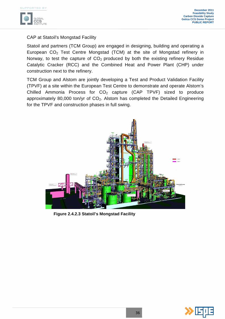
CAP at Statoil’s Mongstad Facility
Statoil and partners (TCM Group) are engaged in designing, building and operating a European CO2 Test Centre Mongstad (TCM) at the site of Mongstad refinery in Norway, to test the capture of CO2 produced by both the existing refinery Residue Catalytic Cracker (RCC) and the Combined Heat and Power Plant (CHP) under construction next to the refinery.
TCM Group and Alstom are jointly developing a Test and Product Validation Facility (TPVF) at a site within the European Test Centre to demonstrate and operate Alstom’s Chilled Ammonia Process for CO2 capture (CAP TPVF) sized to produce approximately 80,000 ton/yr of CO2. Alstom has completed the Detailed Engineering for the TPVF and construction phases in full swing.
Figure 2.4.2.3 Statoil’s Mongstad Facility
37
December 2011 Feasibility Study
Carbon Dioxide Capture Getica CCS Demo Project
PUBLIC REPORT
3. PROJECT TECHNICAL DATA
3.1 Carbon Dioxide Capture Plant (CCP)
Considering that the Romanian demonstrative project will be implemented at an existing power plant, the chosen Carbon Capture Technology for the Power Unit no. 6 of CE Turceni is post combustion technology. The Power Unit no. 6 will be retrofitted in the next three years.
The Carbon Capture Plant (CCP) will be based upon the absorption of the CO2 from the flue gases using Alstom’s Chilled Ammonia Process (CAP). This technology is easy to integrate in an existing Power Plant.
The selected Alstom technology was already implemented in a number of successful pilot and demonstration units across the globe. The experience gained in the pilot plants will be included in the design of the Getica CCS Demo Project carbon capture plant. The most recent results of operating 20 MWe CAP in AEP Mountaineer announced in May 2011 confirm the assumptions taken into consideration in this Feasibility Study.
The objective of the CAP demonstration plant is to further validate the process under industrial scale conditions.
The CCP will treat an equivalent flow of flue gases, for 250 MWe of gross electrical output before capture from Unit no. 6 WFGD exhaust. This project, when operational, will have a CO2 capture rate of more than 85% from the flue gases flow. The captured CO2 stream will be compressed and transported by pipeline for sequestration in deep saline aquifers.
The Chilled Ammonia Process is a new technology with encouraging prospects regarding performance and emissions based on extensive laboratory and pilot testing.
38
December 2011 Feasibility Study
Carbon Dioxide Capture Getica CCS Demo Project
PUBLIC REPORT
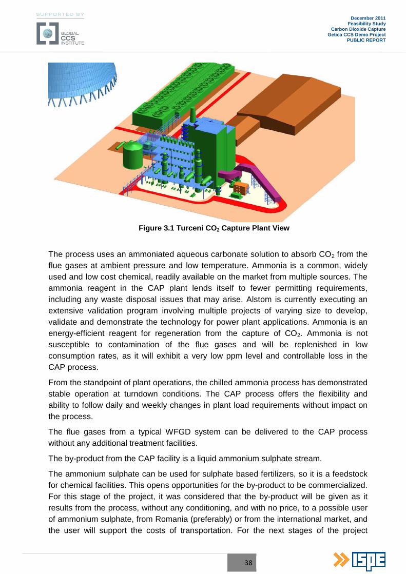
Figure 3.1 Turceni CO 2 Capture Plant View
The process uses an ammoniated aqueous carbonate solution to absorb CO2 from the flue gases at ambient pressure and low temperature. Ammonia is a common, widely used and low cost chemical, readily available on the market from multiple sources. The ammonia reagent in the CAP plant lends itself to fewer permitting requirements, including any waste disposal issues that may arise. Alstom is currently executing an extensive validation program involving multiple projects of varying size to develop, validate and demonstrate the technology for power plant applications. Ammonia is an energy-efficient reagent for regeneration from the capture of CO2. Ammonia is not susceptible to contamination of the flue gases and will be replenished in low consumption rates, as it will exhibit a very low ppm level and controllable loss in the CAP process.
From the standpoint of plant operations, the chilled ammonia process has demonstrated stable operation at turndown conditions. The CAP process offers the flexibility and ability to follow daily and weekly changes in plant load requirements without impact on the process.
The flue gases from a typical WFGD system can be delivered to the CAP process without any additional treatment facilities.
The by-product from the CAP facility is a liquid ammonium sulphate stream.
The ammonium sulphate can be used for sulphate based fertilizers, so it is a feedstock for chemical facilities. This opens opportunities for the by-product to be commercialized. For this stage of the project, it was considered that the by-product will be given as it results from the process, without any conditioning, and with no price, to a possible user of ammonium sulphate, from Romania (preferably) or from the international market, and the user will support the costs of transportation. For the next stages of the project
39
December 2011 Feasibility Study
Carbon Dioxide Capture Getica CCS Demo Project
PUBLIC REPORT
(FEED), if the discussions and agreements with the potential local users or buyers of the by-product will be unsuccessful, a market analysis shall be conducted for the European Community markets.
Since gaseous emission and liquid waste streams are harmless, no additional treatment facilities are required.
3.1.1 Basis of Design for CCP
The Carbon Capture Plant (CCP) shall be sized to process 1,900,000 t/h of wet flue gases.
The following units are included in the proposed capture component:
• Flue gases cooling;
• Carbon dioxide removal (CAP);
• Carbon dioxide compression;
• Auxiliary/utility systems;
• Utility distribution system inside battery limits (including cooling water pump).
On-Stream Time: 7,600 hours/year.
Turndown Requirements:
The CCS shall be designed to operate with a turndown capacity of 50% of the normal capacity (50% of the design flue gases flow to the CCP).
Raw Flue Gases:
Conditions:
• Temperature °C 66
• Differential pressure mmH2O 10.189
• Absolute pressure @ 760 mmH2O bar(a) 1.014
Composition, wet:
• Oxygen (O2) % wt 5.00
• Carbon dioxide (CO2) % wt 15.00
• Nitrogen (N2) % wt 62.00
• Water (H2O) % wt 17.00
40
December 2011 Feasibility Study
Carbon Dioxide Capture Getica CCS Demo Project
PUBLIC REPORT
• Sulphur dioxide (SO2) mg/Nm3 200
• Nitrogen oxides (NOx) mg/Nm3 200
• Particulate matter mg/Nm3 20
CO2 product:
Conditions:
• Temperature °C 30 ÷ 40
• Pressure bar(a) 120
Composition:
• Carbon Dioxide (CO2) Vol% max. 99.7
• Oxygen (O2) ppmv < 50
• Nitrogen (N2) ppmv < 2500
• Water (H2O) ppmv < 50
• Solvent (Ammonia) ppmv < 150
There is no requirement for storing CO2 product within the power plant. The supercritical liquid CO2 product shall be sent to the CO2 transport pipeline to the deep saline aquifer storage.
3.1.2 Chilled Ammonia Process (CAP) Description
The Chilled Ammonia Process uses an ammoniated aqueous carbonate solution to absorb CO2 from the flue gases at ambient pressure and low temperature. Unlike in other technologies, the ammonium solution stability is not affected by oxygen or acidic trace components present in the flue gases. The CAP process features a comparatively low parasitic load, which offers savings in OPEX over the life of the plant. Operation at low process temperatures allows the use of waste energy that is not available to other post-combustion CO2 capture technologies. Since gaseous emission and liquid waste streams are harmless, no additional treatment facilities are required.
The reagent employed in the CAP process is ammonia, a low-cost chemical readily available on the global market from multiple sources. Since ammonia’s availability influences both initial fill and replenishment during operation, it is a factor for both initial capital cost and operational and maintenance (O&M) considerations. Ammonia is an energy-efficient reagent for regeneration from the capture of CO2. Ammonia is not susceptible to contamination of the flue gases and will be replenished in low
41
December 2011 Feasibility Study
Carbon Dioxide Capture Getica CCS Demo Project
PUBLIC REPORT
consumption rates, as it will exhibit a very low (ppm level) and controllable loss in the CAP process.
In addition, the flue gases from a typical FGD system can be delivered to the CAP process. Other technologies may require costly FGD performance upgrades to obtain high SOx removal efficiencies.
From the standpoint of plant operations, the chilled ammonia process has demonstrated stable operation at turndown conditions. The CAP process offers the flexibility and ability to follow daily and weekly changes in plant load requirements in the typical range of 25÷100% without impact on the process.
As ammonia is a common and widely used chemical, the ammonia reagent in the CAP plant also lends itself to fewer permitting requirements, including any waste disposal issues that may arise. The by-product from the CAP facility is a liquid ammonium sulphate stream with commercial value as a fertilizer. Optionally the ammonia is removed in a dedicated Ammonia Recovery Unit, and in this case the final by-product is gypsum.
The power consumption for CO2 compression represents a substantial part of the total power consumption for the different CO2 technologies. The CAP concept involves the production of higher pressure CO2, resulting in significantly lower power consumption of CO2 compression equipment.
CAP Process Chemistry
The Chilled Ammonia process chemistry comprises gas/liquid phase mass transfer followed by chemical reactions in the liquid phase. The overall chemical reactions associated with the Chilled Ammonia Process carbon capture technology are depicted below:
CO2 (g) �==� CO2 (aq)
Equation 1
NH3(aq) + CO2 (aq) + H2O (aq) �==� (NH4)HCO3 (aq)
Equation 2
(NH4)2CO3 (aq) �==� (NH4)NH2CO2 (aq) + H2O (aq)
Equation 3
The chemical reactions in the Chilled Ammonia Process are all reversible and their direction depends on pressure, temperature and concentration in the system. At low temperature, Equation 1 to Equation 3 are exothermic reactions from a left to right direction requiring removal of heat from the process in order to maintain the desired absorption temperature.
42
December 2011 Feasibility Study
Carbon Dioxide Capture Getica CCS Demo Project
PUBLIC REPORT
At high temperature Equation 1 to Equation 3 are endothermic reactions from a right to left direction that require energy to release gaseous CO2. In addition, chemical reactions associated with the removal of residual SO2 from the flue gas occur as described below:
SO2 (g) + 2NH3 (g) + H2O (aq) �==� (NH4)2SO3 (aq)
Equation 4
(NH4)2SO3 (aq) + 1/2O2 (g) �==� (NH4)2SO4 (aq)
Equation 5
Other trace components, e.g. chlorides and fluorides, particulates are removed upstream of the absorption section.
To minimize gaseous NH3 emissions, CO2 absorption is carried out at low flue gas temperatures below ambient condition. The chemical reactions in the liquid phase comprise the formation of ammonium carbonate ((NH4)2CO3), ammonium bi-carbonate ((NH4)HCO3) and ammonium carbamate ((NH4)NH2CO2).
CAP Process Design
The following section gives a general description of Chilled Ammonia Process (CAP).
CAP Scope of Plant
The Chilled Ammonia Process consists of the following process units, as depicted:
• CAP Flue Gases Conditioning;
• CAP CO2 Absorption;
• CAP Water Wash and CO2/NH3 Stripping;
• CAP regeneration;
• Chiller (Refrigerant) System ;
• CO2 Compression and Dehydration.
Figure 3.1.2.1 gives a simplified Process Scheme of the CAP.
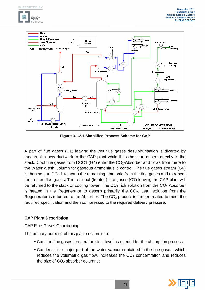
43
December 2011 Feasibility Study
Carbon Dioxide Capture Getica CCS Demo Project
PUBLIC REPORT
Figure 3.1.2.1 Simplified Process Scheme for CAP
A part of flue gases (G1) leaving the wet flue gases desulphurisation is diverted by means of a new ductwork to the CAP plant while the other part is sent directly to the stack. Cool flue gases from DCC1 (G4) enter the CO2-Absorber and flows from there to the Water Wash Column for gaseous ammonia slip control. The flue gases stream (G6) is then sent to DCH1 to scrub the remaining ammonia from the flue gases and to reheat the treated flue gases. The residual (treated) flue gases (G7) leaving the CAP plant will be returned to the stack or cooling tower. The CO2 rich solution from the CO2 Absorber is heated in the Regenerator to desorb primarily the CO2. Lean solution from the Regenerator is returned to the Absorber. The CO2 product is further treated to meet the required specification and then compressed to the required delivery pressure.
CAP Plant Description
CAP Flue Gases Conditioning
The primary purpose of this plant section is to:
• Cool the flue gases temperature to a level as needed for the absorption process;
• Condense the major part of the water vapour contained in the flue gases, which reduces the volumetric gas flow, increases the CO2 concentration and reduces the size of CO2 absorber columns;
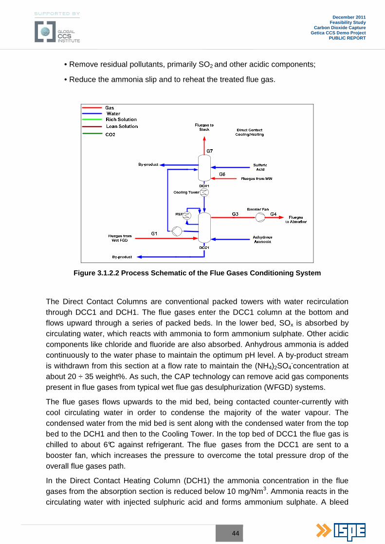
44
December 2011 Feasibility Study
Carbon Dioxide Capture Getica CCS Demo Project
PUBLIC REPORT
• Remove residual pollutants, primarily SO2 and other acidic components;
• Reduce the ammonia slip and to reheat the treated flue gas.
Figure 3.1.2.2 Process Schematic of the Flue Gases Conditioning System
The Direct Contact Columns are conventional packed towers with water recirculation through DCC1 and DCH1. The flue gases enter the DCC1 column at the bottom and flows upward through a series of packed beds. In the lower bed, SOx is absorbed by circulating water, which reacts with ammonia to form ammonium sulphate. Other acidic components like chloride and fluoride are also absorbed. Anhydrous ammonia is added continuously to the water phase to maintain the optimum pH level. A by-product stream is withdrawn from this section at a flow rate to maintain the (NH4)2SO4
-concentration at about 20 ÷ 35 weight%. As such, the CAP technology can remove acid gas components present in flue gases from typical wet flue gas desulphurization (WFGD) systems.
The flue gases flows upwards to the mid bed, being contacted counter-currently with cool circulating water in order to condense the majority of the water vapour. The condensed water from the mid bed is sent along with the condensed water from the top bed to the DCH1 and then to the Cooling Tower. In the top bed of DCC1 the flue gas is chilled to about 6°C against refrigerant. The flue gases from the DCC1 are sent to a booster fan, which increases the pressure to overcome the total pressure drop of the overall flue gases path.
In the Direct Contact Heating Column (DCH1) the ammonia concentration in the flue gases from the absorption section is reduced below 10 mg/Nm3. Ammonia reacts in the circulating water with injected sulphuric acid and forms ammonium sulphate. A bleed
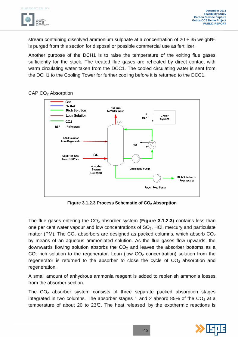
45
December 2011 Feasibility Study
Carbon Dioxide Capture Getica CCS Demo Project
PUBLIC REPORT
stream containing dissolved ammonium sulphate at a concentration of 20 ÷ 35 weight% is purged from this section for disposal or possible commercial use as fertilizer.
Another purpose of the DCH1 is to raise the temperature of the exiting flue gases sufficiently for the stack. The treated flue gases are reheated by direct contact with warm circulating water taken from the DCC1. The cooled circulating water is sent from the DCH1 to the Cooling Tower for further cooling before it is returned to the DCC1.
CAP CO2 Absorption
Figure 3.1.2.3 Process Schematic of CO 2 Absorption
The flue gases entering the CO2 absorber system (Figure 3.1.2.3 ) contains less than one per cent water vapour and low concentrations of SO2, HCl, mercury and particulate matter (PM). The CO2 absorbers are designed as packed columns, which absorb CO2 by means of an aqueous ammoniated solution. As the flue gases flow upwards, the downwards flowing solution absorbs the CO2 and leaves the absorber bottoms as a CO2 rich solution to the regenerator. Lean (low CO2 concentration) solution from the regenerator is returned to the absorber to close the cycle of CO2 absorption and regeneration.
A small amount of anhydrous ammonia reagent is added to replenish ammonia losses from the absorber section.
The CO2 absorber system consists of three separate packed absorption stages integrated in two columns. The absorber stages 1 and 2 absorb 85% of the CO2 at a temperature of about 20 to 23°C. The heat released by the exothermic reactions is
46
December 2011 Feasibility Study
Carbon Dioxide Capture Getica CCS Demo Project
PUBLIC REPORT
removed by separate external circulating cooling loops for each absorber stage. The heat is rejected to the refrigerant from the chiller system.
The purpose of the 3rd packed absorber stage is to reduce the amount of ammonia leaving the absorber section. This is accomplished by sending cold rich solution at a temperature of about 5°C to the top of the 3 rd stage. The low ammonia equilibrium pressure at this temperature favours the absorption of gaseous ammonia into the liquid phase. The solution to the 3rd absorber stage is cooled against refrigerant from the chiller system. The flue leaving the 3rd absorber stage is sent to the Water Wash Column.
Rich solution is withdrawn from the bottoms of the 1st absorber stage and pumped to the Regenerator. Lean solution from the Regenerator is sent to the Absorber.
General terms defining CO2 Loading and Solution Strength:
The CO2 loading is expressed in the R-value which is the ratio of “moles NH3 to moles CO2 in solution”.
A high R value (lean solution) means low CO2 loading and vice versa.
The solution strength is expressed either in Ammonia Molarity: “Moles NH3 per volume of solution” or in Ammonia Molality “moles NH3 per kg of water” in solution.
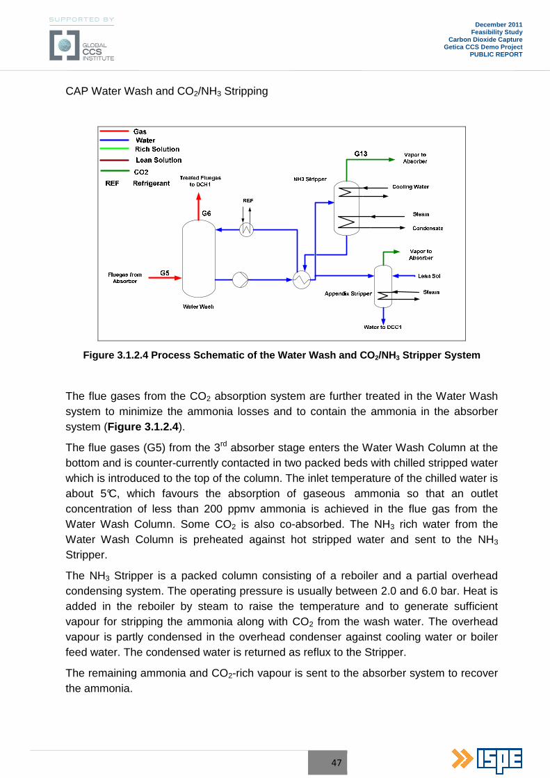
47
December 2011 Feasibility Study
Carbon Dioxide Capture Getica CCS Demo Project
PUBLIC REPORT
CAP Water Wash and CO2/NH3 Stripping
Figure 3.1.2.4 Process Schematic of the Water Wash and CO 2/NH3 Stripper System
The flue gases from the CO2 absorption system are further treated in the Water Wash system to minimize the ammonia losses and to contain the ammonia in the absorber system (Figure 3.1.2.4 ).
The flue gases (G5) from the 3rd absorber stage enters the Water Wash Column at the bottom and is counter-currently contacted in two packed beds with chilled stripped water which is introduced to the top of the column. The inlet temperature of the chilled water is about 5°C, which favours the absorption of gaseous ammonia so that an outlet concentration of less than 200 ppmv ammonia is achieved in the flue gas from the Water Wash Column. Some CO2 is also co-absorbed. The NH3 rich water from the Water Wash Column is preheated against hot stripped water and sent to the NH3
Stripper.
The NH3 Stripper is a packed column consisting of a reboiler and a partial overhead condensing system. The operating pressure is usually between 2.0 and 6.0 bar. Heat is added in the reboiler by steam to raise the temperature and to generate sufficient vapour for stripping the ammonia along with CO2 from the wash water. The overhead vapour is partly condensed in the overhead condenser against cooling water or boiler feed water. The condensed water is returned as reflux to the Stripper.
The remaining ammonia and CO2-rich vapour is sent to the absorber system to recover the ammonia.
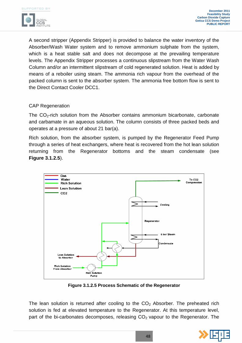
48
December 2011 Feasibility Study
Carbon Dioxide Capture Getica CCS Demo Project
PUBLIC REPORT
A second stripper (Appendix Stripper) is provided to balance the water inventory of the Absorber/Wash Water system and to remove ammonium sulphate from the system, which is a heat stable salt and does not decompose at the prevailing temperature levels. The Appendix Stripper processes a continuous slipstream from the Water Wash Column and/or an intermittent slipstream of cold regenerated solution. Heat is added by means of a reboiler using steam. The ammonia rich vapour from the overhead of the packed column is sent to the absorber system. The ammonia free bottom flow is sent to the Direct Contact Cooler DCC1.
CAP Regeneration
The CO2-rich solution from the Absorber contains ammonium bicarbonate, carbonate and carbamate in an aqueous solution. The column consists of three packed beds and operates at a pressure of about 21 bar(a).
Rich solution, from the absorber system, is pumped by the Regenerator Feed Pump through a series of heat exchangers, where heat is recovered from the hot lean solution returning from the Regenerator bottoms and the steam condensate (see Figure 3.1.2.5 ).
Figure 3.1.2.5 Process Schematic of the Regenerator
The lean solution is returned after cooling to the CO2 Absorber. The preheated rich solution is fed at elevated temperature to the Regenerator. At this temperature level, part of the bi-carbonates decomposes, releasing CO2 vapour to the Regenerator. The
49
December 2011 Feasibility Study
Carbon Dioxide Capture Getica CCS Demo Project
PUBLIC REPORT
remainder of the rich solution is contacted with rising hot vapour, which is generated in the Regenerator Reboiler. At increasing temperature, more bi-carbonates decompose, releasing primarily CO2 and small amounts of NH3 and H2O.
The CO2 rich gas from top of the Regenerator column is cooled to 30°C in the downstream “CO2 Wash Column“ (not shown in Figure 2.1.3.2.5 ) by direct contact cooling with water to condense excess water and to lower the ammonia content in the CO2 gas. The CO2 loading of the lean solution depends on the temperature.
The pressure of the CO2 product leaving the Regenerator and CO2 Wash Column is much higher than for other post combustion carbon capture technologies resulting in a significant reduction of electrical power (up to 60%) associated with downstream CO2 compression. However, the operating pressure of the regenerator system can be adjusted to optimize the overall performance of the CCP and the Steam Turbine of the power plant.
CO2 Product Dehydration and Compression
The cooled CO2 stream leaves the Regenerator/CO2 Wash System at 20.5 bar and about 40°C. The pressure is controlled by a pressur e controller in the CO2 product line which manipulates the inlet guide vanes at the CO2 compressor suction.
The CO2 compression system consists of an integrally geared centrifugal compressor with two-stages driven by an electrical motor, intercoolers and separators, a CO2 Chiller/Liquefier, and a liquid CO2 Pump. The compression ratio of each compressor stage is approximately 1.7. Liquefied CO2 product from the surge drum is pumped to the required battery limit pressure (see simplified scheme below).
At this inlet temperature of 40°C, the water vapour content is too high for transportation/sequestration into suitable geological formations. Therefore, a dehydration step is provided between the compression stages to adjust the water content to less than 50 ppmv of the CO2 product stream.
For dehydration a “mol sieve” zeolite type adsorption system is envisaged, which is most suitable for the low moisture content. Three adsorber vessels are provided on the 1st stage discharge side. One adsorber is on regeneration while two are in adsorption cycle.
For regeneration about 10% dry CO2 product is taken from the outlet of the running adsorbers and is heated by means of an electrical heater. The regeneration gas is recycled back to the 1st stage suction drum of the CO2 compressor.
The pressure required for the CO2 gas at the battery limits depends on the conditions for transport and storage and is usually between 100 and 150 bar. The two-stage compressor increases the pressure to about 61 bar. The final pressure of 120 bar is achieved by means of a liquid pump for the Turceni plant.
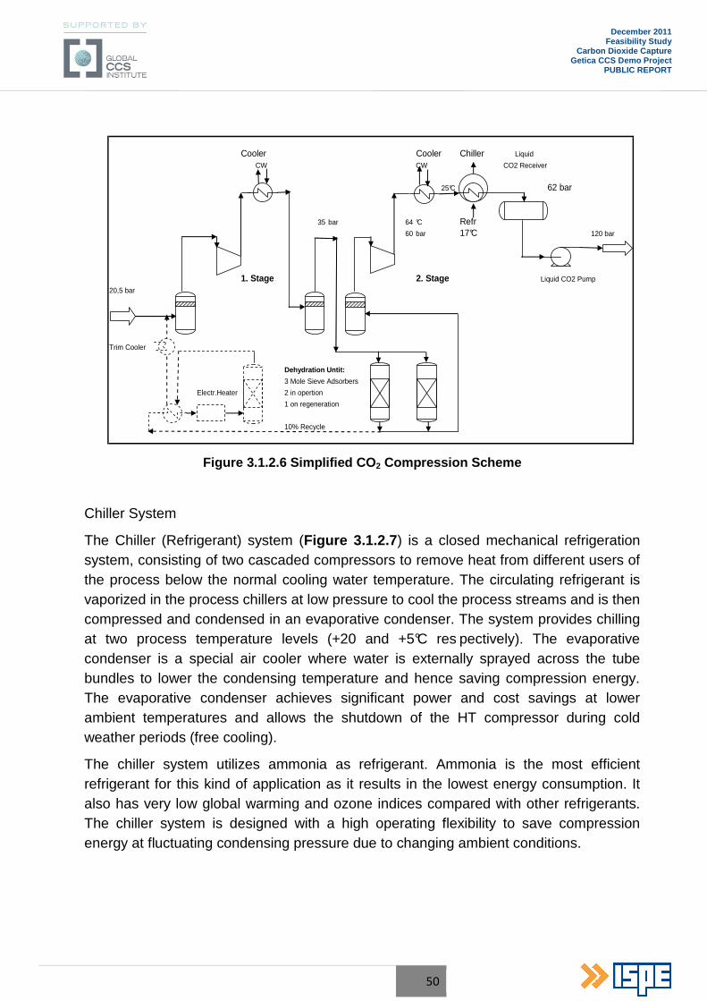
50
December 2011 Feasibility Study
Carbon Dioxide Capture Getica CCS Demo Project
PUBLIC REPORT
Cooler Cooler Chiller Liquid
CW CW CO2 Receiver
25°C 62 bar
35 bar 64 °C Refr60 bar 17°C 120 bar
1. Stage 2. Stage Liquid CO2 Pump
20,5 bar
Trim Cooler
Dehydration Untit:
3 Mole Sieve Adsorbers
Electr.Heater 2 in opertion
1 on regeneration
10% Recycle
Figure 3.1.2.6 Simplified CO 2 Compression Scheme
Chiller System
The Chiller (Refrigerant) system (Figure 3.1.2.7 ) is a closed mechanical refrigeration system, consisting of two cascaded compressors to remove heat from different users of the process below the normal cooling water temperature. The circulating refrigerant is vaporized in the process chillers at low pressure to cool the process streams and is then compressed and condensed in an evaporative condenser. The system provides chilling at two process temperature levels (+20 and +5°C res pectively). The evaporative condenser is a special air cooler where water is externally sprayed across the tube bundles to lower the condensing temperature and hence saving compression energy. The evaporative condenser achieves significant power and cost savings at lower ambient temperatures and allows the shutdown of the HT compressor during cold weather periods (free cooling).
The chiller system utilizes ammonia as refrigerant. Ammonia is the most efficient refrigerant for this kind of application as it results in the lowest energy consumption. It also has very low global warming and ozone indices compared with other refrigerants. The chiller system is designed with a high operating flexibility to save compression energy at fluctuating condensing pressure due to changing ambient conditions.
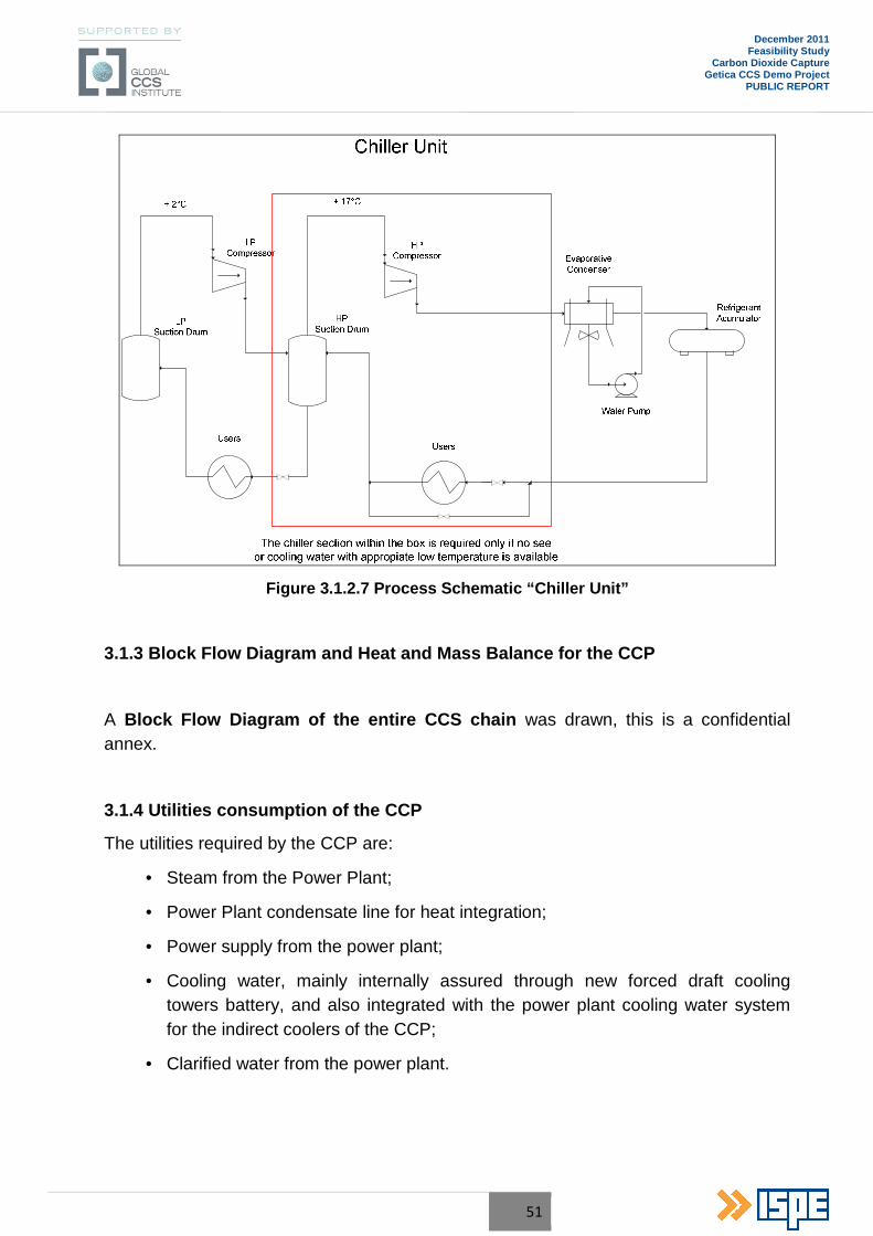
51
December 2011 Feasibility Study
Carbon Dioxide Capture Getica CCS Demo Project
PUBLIC REPORT
Figure 3.1.2.7 Process Schematic “Chiller Unit”
3.1.3 Block Flow Diagram and Heat and Mass Balance for the CCP
A Block Flow Diagram of the entire CCS chain was drawn, this is a confidential annex.
3.1.4 Utilities consumption of the CCP
The utilities required by the CCP are:
• Steam from the Power Plant;
• Power Plant condensate line for heat integration;
• Power supply from the power plant;
• Cooling water, mainly internally assured through new forced draft cooling towers battery, and also integrated with the power plant cooling water system for the indirect coolers of the CCP;
• Clarified water from the power plant.

52
December 2011 Feasibility Study
Carbon Dioxide Capture Getica CCS Demo Project
PUBLIC REPORT
3.1.5 Chemicals consumption of the CCP
The CCP will require the following chemicals:
• Anhydrous Ammonia, 100% wt concentration;
• Sulphuric Acid, 93% wt concentration.
3.1.6 Plant effluent data
Gaseous Emissions
The CCP will be designed for 85% CO2 capture rate. The resulting CO2 product flow is based on design flue gases inlet flow.
The following table summarizes the expected continuous gaseous and liquid emissions based on the information given in the design basis.
Table 2.1.3.6.1
Lean CO 2 Flue gases exhausted to atmosphere from the CCP
100% Flow
Parameter Unit Value
Wet Dry
Temperature oC 56
Pressure bar (a) 1.01
Flue Gas Mass Flow Rate kg/h 1,500,000 1,300,000
H2O wt. - % 10.90 -
CO2 wt. - % 2.83 3.18
O2 wt. - % 6.73 7.55
N2 + Ar wt. - % 79.54 89.27
SO2 mg/Nm3 0 0
SO3 mg/Nm3 Traces Traces
HCl mg/Nm3 0 0
HF mg/Nm3 0 0
NOx mg/Nm3 188* 224*
NH3 mg/Nm3 < 10 < 10
Dust mg/Nm3 0 0
*Considering 5% NO2 in NOx
For 50% load of the CCP the only variation is on the flue gases mass flow rate.
53
December 2011 Feasibility Study
Carbon Dioxide Capture Getica CCS Demo Project
PUBLIC REPORT
Liquid Effluents
Ammonium Sulphate Bleed Stream
A liquid stream containing ammonium sulphate is bled from the DCC/DCH.
Ammonium sulphate solution from the DCC and DCH is containing residual contaminants captured from the flue gas.
Process Water Drains
All process water from the CAP is collected in a closed system and recycled back to the plant.
Cooling Tower Blow-down
In general the blow-down water from the CCP cooling tower can be routed to power plant cooling water blow-down system or as make-up for the evaporative condenser.
At Turceni PP the Cooling Tower blow down will be used as make-up water for the evaporative condenser.
3.1.7 Wastes from CCP
The only by-product produced by the Chilled Ammonia Process is the Ammonium Sulphate
The ammonium sulphate (solution with 30% concentration) can be used for sulphate based fertilizers, so it is a feedstock for chemical facilities. This opens opportunities for the by-product to be commercialized. In Romania there are some chemical factories which produce fertilizers both for internal consumption and export.
For this stage of the project it was considered that the by-product will be given as it results from the process, without any conditioning, and with no price, to a possible user of ammonium sulphate, from Romania (preferably) or from the international market, with the user supporting the costs of transportation. For the next stages of the project (FEED), if the discussions and agreements with the potential local users or buyers of the by-product will be unsuccessful, a market analysis shall be conducted for the European Community market.
A temporary storage tank will be done, equivalent of about 10 days of continuous operation.
Another envisaged alternative is on-site treatment of the by-product using reaction of hydrated lime with ammonium sulphate to form gypsum and ammonia gas.
Precipitation of gypsum from ammonium sulphate is a well-known and commercially available process and the reaction is completed using commercially available equipment. The gypsum by-product has the same qualities as gypsum from the FGD
54
December 2011 Feasibility Study
Carbon Dioxide Capture Getica CCS Demo Project
PUBLIC REPORT
plant and can be disposed the same way. Ammonia is discharged from the process in gaseous form and it is returned to the CCP for reaction with CO2 in the flue gases. The water filtrated from the gypsum filter, used in this process, can be reused in the CCP. It has few of the dissolved contaminants than FGD water and it can be treated in the waste water plant of the power plant or in a separate small plant dedicated for the CCP.
This kind of installation is not considered for this stage of the project, and will be assessed as necessary during the FEED study, and only if the results of the market analysis for the ammonium sulphate are unsatisfactory.
Discontinuous Solid Wastes
No solid waste is generated by the CAP, only potential filter cake from machinery system (e.g. lube oil filters) need to be considered. The CO2 dryer desiccant after 5 years life time will be returned to the vendor for exchange with the new desiccant.
These are minor, non-critical wastes and they can be disposed of through the existing disposal infrastructure available in the power plant.
Other wastes
Intermittent solid wastes are expected from cartridges and pump filters, and other wastes coming from the operation personnel. These wastes will be selectively stored temporary within CCP site and afterwards they will be evacuated from the site by specialized companies for the waste category, in accordance with the laws in force.
The Carbon Capture Plant will not generate waste waters. The condensate water from the flue gases is used within the process.
The rain water is collected and sent to the Turceni PP rain water sewage system.
3.1.8 Process equipment list
The main process equipment list, with the main characteristics is presented in a confidential annex.
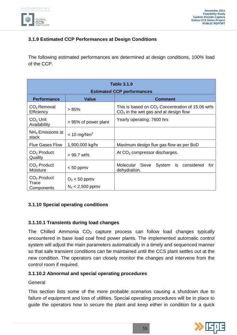
55
December 2011 Feasibility Study
Carbon Dioxide Capture Getica CCS Demo Project
PUBLIC REPORT
3.1.9 Estimated CCP Performances at Design Conditions
The following estimated performances are determined at design conditions, 100% load of the CCP.
Table 3.1.9
Estimated CCP performances
Performance Value Comment
CO2 Removal Efficiency > 85% This is based on CO2 Concentration of 15.06 wt%
CO2 in the wet gas and at design flow
CO2 Unit Availability > 95% of power plant Yearly operating: 7600 hrs
NH3 Emissions at stack < 10 mg/Nm3
Flue Gases Flow 1,900,000 kg/hr Maximum design flue gas flow as per BoD
CO2 Product Quality > 99.7 wt% At CO2 compressor discharges.
CO2 Product Moisture < 50 ppmv Molecular Sieve System is considered for
dehydration.
CO2 Product Trace Components
O2 < 50 ppmv
N2 < 2,500 ppmv
3.1.10 Special operating conditions
3.1.10.1 Transients during load changes
The Chilled Ammonia CO2 capture process can follow load changes typically encountered in base load coal fired power plants. The implemented automatic control system will adjust the main parameters automatically in a timely and sequenced manner so that safe transient conditions can be maintained until the CCS plant settles out at the new condition. The operators can closely monitor the changes and intervene from the control room if required.
3.1.10.2 Abnormal and special operating procedures
General
This section lists some of the more probable scenarios causing a shutdown due to failure of equipment and loss of utilities. Special operating procedures will be in place to guide the operators how to secure the plant and keep either in condition for a quick
56
December 2011 Feasibility Study
Carbon Dioxide Capture Getica CCS Demo Project
PUBLIC REPORT
restart or prepare the CAP plant for long term shutdown to perform major maintenance work.
Below only some scenarios are described which can lead to an abnormal shutdown.
Loss of Steam
If steam is lost to the regenerator, the production of CO2 gas will stop and the regenerator pressure is lost. The flue gas flow has to be stopped. The solution feed streams to the regenerator shall be stopped. All circulation flows of the DCC/DCH, absorbers and water wash column shall be kept in service while chilling is continued to maintain low temperatures.
Loss of Flue Gases
A phased plant wide shutdown is required. All heat input to the plant shall be stopped. Maximum cooling and chilling of the circulating flows shall be maintained in operation as long as possible. The stripper shall be kept in operation to supply stripped water to the top of the water wash column.
Loss of Booster Fan
Loss of the booster fan causes loss of flue gases (see above).
Loss of Refrigerant System
In case the refrigerant system fails, the CCS plant needs to be shutdown. The flue gas flow to the plant shall be stopped. Immediate shutdown of all heat input to the regenerator and strippers is required. The rich solution lines to the regenerator shall be closed. The circulation flows of the absorbers and the water wash column shall be stopped.
Loss of Absorbent Liquid
Partial Loss of absorbent liquid (solution) requires the shutdown of the CCP plant.
Loss of Power Supply
In case of power failure supply the CCP will shut down automatically and the flow control and on/ off valves are designed to operate as fail-open/close to protect the plant and to assure a safe restart.
3.1.10.3 Restart after emergency shutdown
Restart of the process after an abnormal shutdown shall be in accordance with the normal start-up procedure.
57
December 2011 Feasibility Study
Carbon Dioxide Capture Getica CCS Demo Project
PUBLIC REPORT
3.1.11 Regular maintenance
General
Some routine activities will be required to be performed on the plant equipment to maintain normal operation and performance.
Cleaning gas analyser cells
The gas analyser cells will be cleaned routinely (expected to be monthly). This will maintain good analyser performance and operation. The sample cells will be removed from service and will be internally inspected and cleaned. The sample cells will then be replaced and the analysers will be placed back in service.
Pumps
No normal maintenance will be required for the circulation pumps to be operated at full performance. It is possible that lubricant levels will have to be refilled at intervals to be determined by actual practice.
Column packing
The column packing will not normally require service. If the column packing becomes plugged, process operating conditions will require adjustment to reduce or prevent plugging.
The experience show that plugged column packing can be easily unplugged. Operation at conditions where plugging does not occur will eventually restore the packing to the original state.
Absorbent chemistry
The chemistry of the absorbent solution (water with ammonia and CO2) may become less efficient and analysis may be required to determine how to maintain effectiveness. Purging of solution may be required or more vigorous CO2 regeneration may be required.
Outages
If an outage occurs in the supply of flue gas to the process, the process can be placed in temporary shutdown or can be maintained in operation but with no CO2 scrubbing occurring
58
December 2011 Feasibility Study
Carbon Dioxide Capture Getica CCS Demo Project
PUBLIC REPORT
3.1.12 Rotating equipment engineering
3.1.12.1 CO2 compression concept
The CO2 captured in the CAP component shall be then pressurized to the required boundary limits, which for this study is equivalent to 120 bar.
In order to optimize the compression process, the CO2 will be pressurize by means of a compressor from 20 bar to 60 bar, then subcritical cooled to reduce its volume by using the available cooling water and in a second stage by means of the chiller Unit to condense the gas as supercritical fluid (liquid).
Once liquefied will be pumped to the required 120 bar, this process is shown on the figure below (values and stages are only as example), the heat recovered in the liquefaction can also be integrated in the process.
The combination of compression, condensation and pumping, brings a higher efficiency as a conventional through compression with only one single machine due to the higher energy demand of compression at higher pressures levels for a single compressor.
To summarize, the energy costs are lower when combined compression is used, also taking into account the condensation costs (where energy can be saved for heat integration as well).
3.1.12.2 CO2 Compressor selection
For this special application, volumes and pressures, there are two different compression concepts available:
• Reciprocating Compressor;
• Centrifugal Compressor.
Reciprocating compressor are positive displacement type, consisting of one or more cylinders each with a piston that moves back and forth, displacing a positive volume with each stroke and for this low volume application and pressure ratio a 1 stage compressor would be suitable.
Centrifugal Compressors are radial flow type, for this application a single shaft or multi-shaft (Integrally Geared) would be adequate.
In the selection of the CO2 compressor the following aspects are considered:
• The high CAPEX and maintenance costs of a reciprocating compressor make this solution total out of range for the required inlet flow;
• The biggest reciprocating compressor studied would be one-stage compressor with two cylinders and a piston diameter of about 600 mm, the price only for the

59
December 2011 Feasibility Study
Carbon Dioxide Capture Getica CCS Demo Project
PUBLIC REPORT
compressor is estimated about 30% more expensive than a 2 stages Integrally Geared Compressor with the same operating conditions;
• The overall volumetric efficiency of this reciprocating machine is about 70%;
• The high CAPEX of a single shaft compressor makes this solution very expensive and due to the small pressure difference available overdesigned for this study.
To have an idea of these values, the table below shows the CAPEX costs of Integrally Geared Compressors (IG) and Single Shaft (SL) for different flows.
In our case the cost of a single shaft compressor is about twice of one 2 stages Integrally Geared Compressor which makes the single shaft compression out of costs range (The Price values must be taken only as indication).
Figure 3.1.12.2 SL vs. IG Costs Chart
Integrally Geared compressors are the most adequate solution for CO2 Compression due to:
• The compressor has the lowed space requirements;
• There are the lowest costs for the surrounding infrastructure;
• It is the most reliable compressor with the lowest maintenance effort;
60
December 2011 Feasibility Study
Carbon Dioxide Capture Getica CCS Demo Project
PUBLIC REPORT
• With starting and switching off single-stages of compressor impellers the compressor can be designed that it can save most of the power consumption due to the free cooling concept;
• The compressor is designed for no oil contamination of the process system;
• Good efficiency values of around 85% makes this option OPEX beneficial.
For these reasons an Integrally Geared Compressor will be chosen as the base case for our CO2 Compression study.
3.1.12.3 CO2 Pumping concept
CO2 after being cooled down to 20°C is pumped from 61 bar to the required 120 bar.
Due to the high volume flow and pressure, a multistage high pressure centrifugal pump is the only suitable design for this application.
The total differential head is more than 800 meters.
3.1.12.4 Compressors for the refrigeration system
The refrigeration system is designed as a cascade system. So the system consists of a low pressure LP compressor for the LT refrigerant level and a HP compressor for the HT temperature level. While the LP compressor has a fixed pressure ratio the pressure ratio for the HP compressor is fluctuating depending of the ambient temperature. The task for the HP refrigeration compressor is to handle the flow and to adopt the total head of the compressor to the existing discharger pressure.
There are two compression principles:
• Positive volume displacement compressors;
• Compressors working and depending on the volume flow (flow compressors).
To the family of the displacement compressors the following compressor types could be used for the compression task:
• Reciprocating compressors;
• Oil injected screw compressors;
• Dry screw compressors.
To the family of the compressors working with a flow principle the following compressor types could be used for the compression task:
• Single shaft radial centrifugal compressor;
• Multi-pinion integrally geared compressors;
• Ramgen shock wave compressor (prototype design).
61
December 2011 Feasibility Study
Carbon Dioxide Capture Getica CCS Demo Project
PUBLIC REPORT
The following aspects were taken into consideration for selection of the refrigeration system compressors:
Reciprocating Compressor: For the considered volume flows (about 100,000 m3/h) we would need minimum 6 parallel compressors. The high costs of all compressors and high space requirements exclude this option.
Furthermore, several compressor reciprocating compressor manufacturers have been contacted but all declined to offer for this application, due to NH3 medium compressors being out of its portfolio.
Screw Compressor: In order to achieve all year round condensing temperatures the discharge pressure shall vary from 14 bar to about 10-11 bar. In winter case a screw compressor cannot pressurize to such small pressure ratio. Furthermore the high flows (about 100,000 m3/h) would suppose many machines in parallel, higher costs and sizes, also the only possibility would be oil injected compressor, increasing with the risk of oil contamination into the process.
Single shaft compressor: Technically a Single-stage compressor is feasible nevertheless; the higher cost in comparison to the Integrally Geared Compressor makes this option out of range for this small polytrophic head.
IG Compressor is the most adequate solution due to:
• The compressor has the lower space requirements;
• There are the lowest costs for the surrounding infrastructure;
• It is the most reliable compressor with the lowest maintenance effort.
• With starting on and switching off single-stages of compressor impellers the compressor can be designed that it can save most of the power consumption due to the free cooling concept.
The compressor is designed for no oil contamination of the process system.
3.1.12.5 Back Pressure Turbine and Generator
The expansion turbine provides extra power generation where energy is removed by reduction in pressure and temperature that otherwise would be wasted.
The expansion turbine is a single casing steam turbine, on skid and coupled through a reduction gear to a generator. An oil system is also installed in the package for lubrication purposes.
3.1.12.6 Expansion Turbines Types
For this application there are two types of turbines, a generator drive to recover energy by pressure reduction and a mechanical driver for compressor, pumps or other rotating equipment.
62
December 2011 Feasibility Study
Carbon Dioxide Capture Getica CCS Demo Project
PUBLIC REPORT
According to the end quality of the steam, there are condensing steam turbines or backpressure turbines, depending if different intermediate pressures are needed, extra extractions and/or admissions levels are necessary.
For our study, the turbine is a backpressure, generator drive steam turbine without extractions.
3.1.13 CCP Layout
Topographical survey
For the location of future construction, a topographical survey in the National Stereographic Projection System was done in November 2010, which presents the planimetric and altimetric measurements of existing land, in the area of interest, namely:
• Construction, existing facilities or in progress;
• Roads;
• Technological and utility/urban networks;
• Green spaces.
This survey presents measurements of elevation of points on land, contour lines of buildings, structures, roads, and underground networks.
Site arrangement and planning
The CCP installation is located in the south-west part of the Turceni PP. The access to the area is served by the existing roads.
The principal and secondary road access inside Turceni PP is from country road 673A.
For the main core CCP footprint area, the following technological units are located on different plots:
• Plot 1 (2,000 m2):
o Inlet of Main Duct from Absorber Unit 6 to CCP;
o MCC Room/ Switch Room for Instruments/ Control Room and Back Pressure Turbine.
• Plot 2 (3,800 m2):
o Direct Contact Cooler, Absorber, NH3 Wash, Direct Contact Heater (as common concrete structure);
o Flue Gases Booster Fan;
o Regenerator and equipment;
o Appendix Stripper and equipment;
63
December 2011 Feasibility Study
Carbon Dioxide Capture Getica CCS Demo Project
PUBLIC REPORT
o Chemical Product Tanks and equipment.
• Plot 3 (1,000 m2):
o CO2 Compressor, LT & HT Refrigeration Compressors and related ancillary equipment.
• Plot 4 (4,300 m2):
o Chiller System (ISBL), Cooling Tower and equipment (OSBL).
Tie-in to existing Facilities
An important fact of the project is the tie-ins to the existing facilities (steam, electrical, cooling water, and process) with the new CCP:
Table 3.1.13
Tie-in to existing facilities list
Item Description
1.
Drinking Water
Fire water as hydrants connected to the Power Plant main ring and local extinguishers
Tie-in to the Power Plant Telephone and PA Systems and interface between CCP Control Room and Unit no. 6 Control Room
2. Tie-in to waste water system Piping Network
3. Tie-in to Make Up Water System
4. Tie-in to Steam Supply
5. Tie-in to Condensate Systems
6. Tie-in to Power Supply
7. Tie-in to CO2 transport pipe line
3.1.14 Electrical and Instrumentation engineering for CCP
A Chilled Ammonia (CAP) has been selected for the Carbon Capture Plant. It is a continuous process with a four-stage integrated gear CO2 compressor and pump concept to provide the demanded pipe line pressure. The whole CCP shall be monitored and controlled from a Distributed Control System whilst the CO2 compressor shall have its own dedicated safeguarding and control system in the form of a safety related Programmable Logic Controller (PLC).
For an on-stream time of more than 7,600 hour/year the following redundancy concept is recommended for the DCS:
•••• Two non-redundant operator stations;
64
December 2011 Feasibility Study
Carbon Dioxide Capture Getica CCS Demo Project
PUBLIC REPORT
•••• A redundant high speed bus system;
•••• Redundant central units;
•••• Redundant power supply modules;
•••• Redundant analogue output modules for controller;
•••• Non redundant modules for indicator;
•••• Redundant digital input and digital output modules;
The following serial DCS interfaces are recommended:
•••• CO2 compressor’s safeguarding system – redundant, RS-485, MODBUS-RTU;
•••• CO2 compressor’s Machine Monitoring System – non redundant, RS-485, MODBUS-RTU;
•••• Electrical Substation - non redundant, RS-485, MODBUS-RTU;
•••• CCP Steam Turbine - non redundant, RS-485, MODBUS-RTU.
The CCP shall be designed according to state of the art engineering practices to achieve the highest mechanical integrity of equipment, piping and instrumentation so that safe operation for the intended operating range is ensured.
In addition, the CCP is protected against contingencies which could lead to unsafe conditions by mechanical safety devices like pressure relief valves and by highly reliable safety instrumentation as a secondary protection level. In addition independent remote alarms will also be displayed to the operator so that he can intervene before a critical condition will occur. The safety instrumented shutdowns are usually redundant and fail-safe.
Signals from the field shall be hardwired from the field transmitter with single cables to field junction boxes, from there with multicore cables to the marshalling and I/O cabinets within the instrument switch room.
A Continuous Emission Monitoring System (CEMS – measuring SO2, NO, CO, CO2 and HCL) for the new flue gases stack is required according to European regulations.
Gas Detection Systems
CO2 gas detectors will be installed on potential leakage points for personal protection. In case of a CO2 release, acoustic and visual alarms shall be provided around the concerned section (horns and flashing lights) and on DCS. The CO2 leakage in function shall then be vented to the atmosphere and/or sent to the stack.
65
December 2011 Feasibility Study
Carbon Dioxide Capture Getica CCS Demo Project
PUBLIC REPORT
Fire Protection
The compressor shelter is fitted with both acoustic and flashing fire detection alarms. The alarm can also be displayed on the DCS screen and automatically shuts down the equipment.
Isolation and Depressurize System
Certain plant sections (compressors, columns, refrigerant system) are provided with an automatic isolation and/or depressurizing system.
Composition Analyser
The following analysers shall be provided for the correct operation of the CCP:
• CO2 analyser in flue gases from HSRG;
• pH analyser in the flue gases cooler sump;
• pH analyser in flue gases condensate;
• SO2 analyser in flue gases to CO2 absorber;
• Continuous Emission Monitoring System (CEMS) in flue gases to stack (SO2, NO, CO, CO2, HCl);
• O2 and N2 analyser in flue gases to CO2 compressor;
• H2O, O2 and N2 analyser in CO2 to pipeline.
3.2 Integration of the Carbon Dioxide Capture Plant intoTurceni PP
The CO2 Capture Plant (CCP) will be based upon the absorption of the CO2 from the flue gases, using Alstom’s Chilled Ammonia Process (CAP). The CCP interfaces directly with various systems of the Turceni Power Plant. Therefore, an integration approach to the project is of significant importance.
The technology for the CO2 capture will be provided by Alstom, which will be involved also in the CCP integration with the Power Plant. The CCP will be implemented at Unit no. 6, which is going to be retrofitted. This will ensure that the overall configuration is optimized, highly efficient and the high availability of the installation.
This work package will include all the modifications necessary to the Power Plant to make it capture ready.
The heat integration between the Power Plant and the Carbon Capture Plant (including the compression stage) has been envisaged to the fullest extent, in order to reduce any additional external requirement and to ensure optimization of the capture process, minimising the investment cost (CAPEX), operation and maintenance costs (OPEX).
66
December 2011 Feasibility Study
Carbon Dioxide Capture Getica CCS Demo Project
PUBLIC REPORT
3.2.1 Flue Gases Supply
The flue gases entering the CCP are taken from the stack of the wet flue gases desulphurization (WFGD) plant. The flow of flue gases is correspondent to an equivalent of 250 MW gross electrical output (as NER 300 definition).
3.2.2 Process Steam interfacing for CCP
Superheated steam is to be extracted from the Turceni Unit no. 6 power plant water steam cycle and transferred to the carbon capture plant (CCP) for heating purposes. The steam is condensed in CCP heat exchangers and returns, as condensate to power plants water/steam cycle.
The chilled ammonia process requires steam at two different pressure levels, an IP-steam at approximately 670 kPa(a) and a LP-steam at approximately 340 kPa(a) at battery limit. The required amount of steam for CCP can be extracted in several ways from the steam turbine. The extracted steam needs to be transported and conditioned for use in the reboilers. For steady CCP operation, the following steam pressures are required at regenerator/stripper inlet:
IP-steam: 670 kPa(a)
LP-steam: 340 kPa(a)
The “post rehabilitation proposal” heat balance of Turceni Unit no. 6 has been used to investigate different thermal integration concepts. The “post rehabilitation proposal” heat balance diagram has been modified in order to have a reliable starting point for all further CCP integration calculations. All thermodynamic calculations are performed with the proven proprietary Alstom process-modeling tool named ALPRO, which is also used for the design and optimization of new power plants. All calculations have been performed in abstract mode, which means without detailed redesign of steam turbine geometry. Hence, mechanical integrity (axial forces, blade stresses, etc.) is not considered and has to be checked in detail for the chosen thermal integration concept. Each steam extraction concept would result in similar mechanical impacts on the steam turbine, due to the high quantity of extracted steam, but differing in intensity.
Five concepts for extracting steam for the carbon capture plant have been investigated:
Concept 1: IP- and LP-steam extraction at hot reheat with downstream auxiliary turbine.
Concept 2: IP-steam extraction at hot reheat line with downstream auxiliary turbine/LP-steam extraction at IP/LP crossover pipe.
Concept 3: IP-steam extraction at cold reheat line with downstream back pressure turbine/ LP-steam extraction at IP/LP crossover pipe.
67
December 2011 Feasibility Study
Carbon Dioxide Capture Getica CCS Demo Project
PUBLIC REPORT
Concept 4: IP-steam extraction at Extraction X5 /LP-steam extraction at IP/LP crossover.
Concept 5: IP-steam supply via steam jet ejector/LP-steam extraction at IP/LP crossover.
The IP-steam condensate and the LP-steam condensate of CCP will be mixed before being subcooled. Subsequently, the steam condensates will be collected and pumped back to the power plant.
For integration of CCP condensates into power plants main condensate system, three tie-in concepts have been investigated:
Tie-in Concept 1: Mixing of CCP condensate with power plant main condensate after LP-preheater No.2.
Tie-in Concept 2: Mixing of CCP condensate with drain of LP-preheater No.3 to LP-preheater No.2.
Tie-in Concept 3: Installation of additional heat-exchanger for subcooling of CCP condensate and heating of main condensate.
In case of regenerator reboiler leakage, CCP condensate will be contaminated with ammonia. In this case, mixing with power plant main condensate after LP-preheater No.2 as mentioned for tie-in concept 1 will also contaminate the power plant’s water/steam cycle. This would lead to impermissible power plant operation, hence tie-in concept 1 is not recommended. The CCP condensate has to enter the condensate polishing plant of the power plant to prevent contamination of water/steam cycle with ammonia. Entering of CCP condensate into power plants condensate polishing plant is considered in tie-in concepts 2 and 3.
In tie-in concept 2, CCP condensate will be mixed with drain from LP-preheater No. 3 to LP-preheater No.2 and guided to condensate polishing plant via LP-preheaters No. 1 and No. 2 and main condenser hotwell.
In tie-in concept 3, CCP condensate will be subcooled with an additional heat-exchanger, so called condensate heat-exchanger and guided to the main condenser hotwell. An additional heat-exchanger (plate and frame), which is not in scope of CCP has to be installed. The additional heat-exchanger will be fed with the main condensate (partial flow), extracted after condensate extraction pump. This partial flow will be heated up to a temperature of approximately 108°C a nd will be integrated afterwards into the main condensate system between LP-preheater No.2 and LP-preheater No.3.
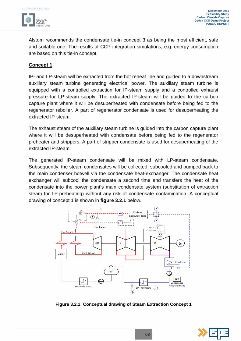
68
December 2011 Feasibility Study
Carbon Dioxide Capture Getica CCS Demo Project
PUBLIC REPORT
Alstom recommends the condensate tie-in concept 3 as being the most efficient, safe and suitable one. The results of CCP integration simulations, e.g. energy consumption are based on this tie-in concept.
Concept 1
IP- and LP-steam will be extracted from the hot reheat line and guided to a downstream auxiliary steam turbine generating electrical power. The auxiliary steam turbine is equipped with a controlled extraction for IP-steam supply and a controlled exhaust pressure for LP-steam supply. The extracted IP-steam will be guided to the carbon capture plant where it will be desuperheated with condensate before being fed to the regenerator reboiler. A part of regenerator condensate is used for desuperheating the extracted IP-steam.
The exhaust steam of the auxiliary steam turbine is guided into the carbon capture plant where it will be desuperheated with condensate before being fed to the regenerator preheater and strippers. A part of stripper condensate is used for desuperheating of the extracted IP-steam.
The generated IP-steam condensate will be mixed with LP-steam condensate. Subsequently, the steam condensates will be collected, subcooled and pumped back to the main condenser hotwell via the condensate heat-exchanger. The condensate heat exchanger will subcool the condensate a second time and transfers the heat of the condensate into the power plant’s main condensate system (substitution of extraction steam for LP-preheating) without any risk of condensate contamination. A conceptual drawing of concept 1 is shown in figure 3.2.1 below.
Figure 3.2.1: Conceptual drawing of Steam Extraction Concept 1
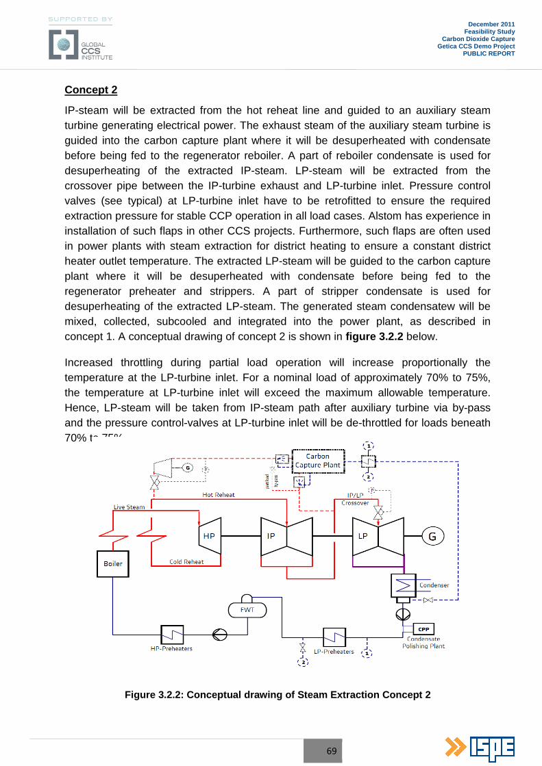
69
December 2011 Feasibility Study
Carbon Dioxide Capture Getica CCS Demo Project
PUBLIC REPORT
Concept 2
IP-steam will be extracted from the hot reheat line and guided to an auxiliary steam turbine generating electrical power. The exhaust steam of the auxiliary steam turbine is guided into the carbon capture plant where it will be desuperheated with condensate before being fed to the regenerator reboiler. A part of reboiler condensate is used for desuperheating of the extracted IP-steam. LP-steam will be extracted from the crossover pipe between the IP-turbine exhaust and LP-turbine inlet. Pressure control valves (see typical) at LP-turbine inlet have to be retrofitted to ensure the required extraction pressure for stable CCP operation in all load cases. Alstom has experience in installation of such flaps in other CCS projects. Furthermore, such flaps are often used in power plants with steam extraction for district heating to ensure a constant district heater outlet temperature. The extracted LP-steam will be guided to the carbon capture plant where it will be desuperheated with condensate before being fed to the regenerator preheater and strippers. A part of stripper condensate is used for desuperheating of the extracted LP-steam. The generated steam condensatew will be mixed, collected, subcooled and integrated into the power plant, as described in concept 1. A conceptual drawing of concept 2 is shown in figure 3.2.2 below.
Increased throttling during partial load operation will increase proportionally the temperature at the LP-turbine inlet. For a nominal load of approximately 70% to 75%, the temperature at LP-turbine inlet will exceed the maximum allowable temperature. Hence, LP-steam will be taken from IP-steam path after auxiliary turbine via by-pass and the pressure control-valves at LP-turbine inlet will be de-throttled for loads beneath 70% to 75%.
Figure 3.2.2: Conceptual drawing of Steam Extraction Concept 2
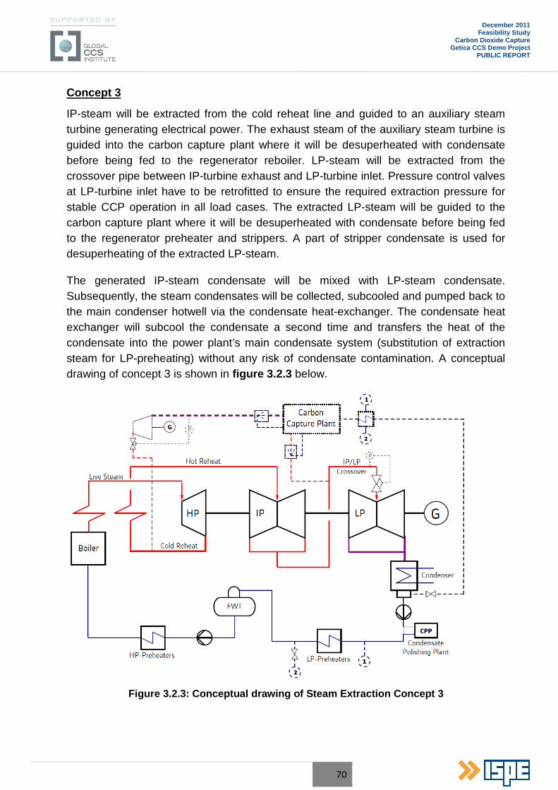
70
December 2011 Feasibility Study
Carbon Dioxide Capture Getica CCS Demo Project
PUBLIC REPORT
Concept 3
IP-steam will be extracted from the cold reheat line and guided to an auxiliary steam turbine generating electrical power. The exhaust steam of the auxiliary steam turbine is guided into the carbon capture plant where it will be desuperheated with condensate before being fed to the regenerator reboiler. LP-steam will be extracted from the crossover pipe between IP-turbine exhaust and LP-turbine inlet. Pressure control valves at LP-turbine inlet have to be retrofitted to ensure the required extraction pressure for stable CCP operation in all load cases. The extracted LP-steam will be guided to the carbon capture plant where it will be desuperheated with condensate before being fed to the regenerator preheater and strippers. A part of stripper condensate is used for desuperheating of the extracted LP-steam.
The generated IP-steam condensate will be mixed with LP-steam condensate. Subsequently, the steam condensates will be collected, subcooled and pumped back to the main condenser hotwell via the condensate heat-exchanger. The condensate heat exchanger will subcool the condensate a second time and transfers the heat of the condensate into the power plant’s main condensate system (substitution of extraction steam for LP-preheating) without any risk of condensate contamination. A conceptual drawing of concept 3 is shown in figure 3.2.3 below.
Figure 3.2.3: Conceptual drawing of Steam Extraction Concept 3
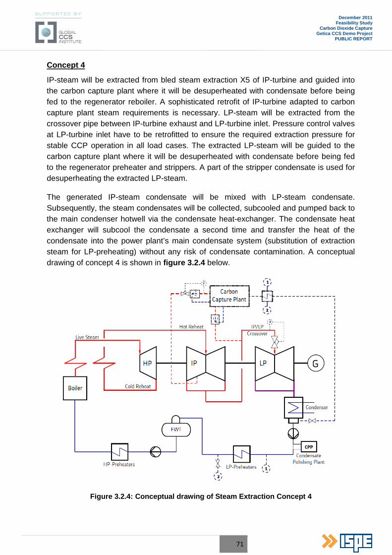
71
December 2011 Feasibility Study
Carbon Dioxide Capture Getica CCS Demo Project
PUBLIC REPORT
Concept 4
IP-steam will be extracted from bled steam extraction X5 of IP-turbine and guided into the carbon capture plant where it will be desuperheated with condensate before being fed to the regenerator reboiler. A sophisticated retrofit of IP-turbine adapted to carbon capture plant steam requirements is necessary. LP-steam will be extracted from the crossover pipe between IP-turbine exhaust and LP-turbine inlet. Pressure control valves at LP-turbine inlet have to be retrofitted to ensure the required extraction pressure for stable CCP operation in all load cases. The extracted LP-steam will be guided to the carbon capture plant where it will be desuperheated with condensate before being fed to the regenerator preheater and strippers. A part of the stripper condensate is used for desuperheating the extracted LP-steam.
The generated IP-steam condensate will be mixed with LP-steam condensate. Subsequently, the steam condensates will be collected, subcooled and pumped back to the main condenser hotwell via the condensate heat-exchanger. The condensate heat exchanger will subcool the condensate a second time and transfer the heat of the condensate into the power plant’s main condensate system (substitution of extraction steam for LP-preheating) without any risk of condensate contamination. A conceptual drawing of concept 4 is shown in figure 3.2.4 below.
Figure 3.2.4: Conceptual drawing of Steam Extraction Concept 4
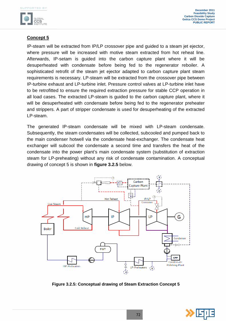
72
December 2011 Feasibility Study
Carbon Dioxide Capture Getica CCS Demo Project
PUBLIC REPORT
Concept 5
IP-steam will be extracted from IP/LP crossover pipe and guided to a steam jet ejector, where pressure will be increased with motive steam extracted from hot reheat line. Afterwards, IP-setam is guided into the carbon capture plant where it will be desuperheated with condensate before being fed to the regenerator reboiler. A sophisticated retrofit of the steam jet ejector adapted to carbon capture plant steam requirements is necessary. LP-steam will be extracted from the crossover pipe between IP-turbine exhaust and LP-turbine inlet. Pressure control valves at LP-turbine inlet have to be retrofitted to ensure the required extraction pressure for stable CCP operation in all load cases. The extracted LP-steam is guided to the carbon capture plant, where it will be desuperheated with condensate before being fed to the regenerator preheater and strippers. A part of stripper condensate is used for desuperheating of the extracted LP-steam.
The generated IP-steam condensate will be mixed with LP-steam condensate. Subsequently, the steam condensates will be collected, subcooled and pumped back to the main condenser hotwell via the condensate heat-exchanger. The condensate heat exchanger will subcool the condensate a second time and transfers the heat of the condensate into the power plant’s main condensate system (substitution of extraction steam for LP-preheating) without any risk of condensate contamination. A conceptual drawing of concept 5 is shown in figure 3.2.5 below.
Figure 3.2.5: Conceptual drawing of Steam Extraction Concept 5
73
December 2011 Feasibility Study
Carbon Dioxide Capture Getica CCS Demo Project
PUBLIC REPORT
Comparison of Steam Extraction Concepts
In all concepts, the swallowing capacity of the boiler feed pump turbine (BFPT) will be insufficient to drive the boiler feed water pump, due to the high amount of steam extraction for the carbon capture plant. The pressure in bled steam extractions will drop, because the pressure profile in turbine shifts in case of steam extraction for CCP, e.g. extraction X3 to BFPT from 450 kPa(a) to 300 kPa(a). This behaviour resembles typical part load behaviour of the IP- and LP-turbines, but with nearly nominal live steam flow at HP-turbine inlet.
A replacement of the existing BFPT by a new BPFT, adapted to new steam parameters due to operation with CCP or a new electric driver (motor) of the boiler feed water pump (BFP) including frequency converter or hydrodynamic coupling for rotational speed control is required.
The electrical power penalty, due to steam extraction for the five mentioned concepts, considering replacement of BFPT or installation of an electric driver for boiler feed water pump have been calculated to make a comparison of the different concepts. An efficiency of 99% for electric BFP driver and a efficiency of 96% for frequency converter are assumed in calculations with electric driven BFP.
The calculations also consider additional auxiliary turbine throttling losses, due to controllability of exhaust pressure and/or extraction pressure for a power plant load range from 50% to 100%. For auxiliary turbine, a polytropic turbine efficiency of 82%, an efficiency of 99% for gearbox and an efficiency of 98% for generator were assumed.
Also considered are pressure losses for the long distance between Turceni 6 turbine and the carbon capture plant, as well as the local resistances and fittings. Based on our experience from current projects and on calculations, the pressure loss should be in a range of 0.3 bar to 0.5 bar.
Due to a fixed boiler design (constant heating surface area), the basis for all calculations was a constant boiler load and a constant ratio of heat for the economizer, evaporator and superheaters to heat for reheat. In case of CCP operation, the pressure profile in turbine shifts due to additional steam extraction. The feed water end temperature at the boiler inlet will decrease and this will affect the boiler outlet temperatures (live steam and/or hot reheat) and has to be checked in detail for chosen steam extraction concept.
Also considered is the impact on the main cooling water system of power plant. Due to steam extraction for CCP steam supply, main condenser load and hence cooling tower load will decrease. Therefore, a decrease in cold cooling water temperature of 0.75K was estimated.
74
December 2011 Feasibility Study
Carbon Dioxide Capture Getica CCS Demo Project
PUBLIC REPORT
The energy consumption for the five mentioned concepts and the two different BFP driver options was estimated to make an energy balance. For power plant operation with chilled ammonia carbon capture plant, concept 2 is the most efficient one.
Due to the throttling losses of the auxiliary turbine to control the exhaust pressure and extraction pressure for a power plant load range from 50% to 100% load and the low auxiliary turbine efficiency of 80% to 85% (depending on turbine design), concept 1 is inefficient. Furthermore, the number of vendors for such turbines (540°C, controlled extraction) is limited and the capital expenditures (CAPEX) are high. Due to the shifted turbine pressure profile in case of CCP operation with concept 1, the feed water end temperature at boiler inlet will decrease to approximately 245°C. This impact will lead to a decrease in hot reheat temperature of approximately 15K, because a designed boiler with fixed heating surface area is not able to compensate this negative effect. Furthermore, the mechanical stresses on HP-turbine blading and the axial forces due to reduced exhaust pressure of approximately 36 bar(a) are highest in this concept and can be a problem.
The thermodynamic calculations have shown, that concept 3 is not suitable, due to wet steam detection at auxiliary turbine outlet. Avoiding this effect would lead to additional performance losses on auxiliary turbine of approximately 1 to 2 MW.
Concept 4 is too high in CAPEX, due to the sophisticated IP-turbine retrofit and has no significant advantage in energy consumption to other concepts. In addition, the steam supply (constant pressure) for the carbon capture plant over the whole power plant load range cannot be ensured.
Concept 5 has no advantage in energy consumption. Furthermore, this technology needs a lot of space for steam jet ejector and pipe works.
Consequently, the Concepts 1, 3, 4 and 5 are not suitable steam extraction concepts at Unit no. 6 of Turceni Power Plant.
3.2.3 Steam extraction and condensate Tie-in Concepts Additional heat integration of carbon capture plant “waste heat” e.g. from stripper overhead condenser and/or lean solution cooler, will have a positive effect on electrical power penalty. The following heat sources are suitable for heat integration and have been investigated:
Stripper Overhead Condenser
Main condensate from power plant, extracted after condensate extraction pump, instead of cooling water can be used for stripper overhead condenser. The main condensate will be preheated, subsequently routed back to the power plant and tied-in after LP-
75
December 2011 Feasibility Study
Carbon Dioxide Capture Getica CCS Demo Project
PUBLIC REPORT
heater No.2. Due to integration of a stripper overhead condenser duty of approximately 21 MWth, an increase in generator power output of 1.4 MW is expected. Furthermore, the utilities of the cooling water system will be reduced which effects electrical consumption of cooling water system equipment, e.g. cooling tower fan or pumps positively in a Range of 0,7 MW.
CO2 Compression
Main condensate from power plant, extracted after condensate extraction pump, instead of cooling water can be used for CO2-compressor cooling. The main condensate will be preheated in 1st and 2nd Stage Intercooler, subsequently routed back to the power plant and tied-in after LP-heater No.2. Due to integration of a total CO2 compression cooling duty of approximately 10 MWth, an increase in generator power output of 0.7 MW is expected. Furthermore, the utilities of the cooling water system will be reduced which effects electrical consumption of cooling water system equipment, e.g. cooling tower fan or pumps positively in a Range of 0.3 MW.
Stripper Overhead Condenser combined with CO2 Compression
A combined heat integration of stripper overhead condenser heat and CO2 compressor intercooler heat will lead to an increase in generator output of 1.8 MW. Due to the heat integration, the cooling water demand of the carbon capture plant will be reduced and hence electrical power for the cooling water pump and the forced cooling tower fan decreases significantly. In total, a combined heat integration reduces the electrical net power penalty by a magnitude of 2.9 MW.
3.2.4 Cooling Water Integration The existing cooling water system is at its limits, therefore no further cooling water capacity for the capture plant is available. A new cooling tower is envisaged for providing the cooling duty required by the capture plant. In addition, an evaporative (air cooled) condenser is provided to reject the heat from the refrigeration system to ambient air. Due to the high evaporation losses in the cooling tower, make up water is required to balance the losses and to compensate the blow down rate.
In general, the cooling demand of the carbon capture plant can be divided into two types:
• Cooling demand for Direct Contact Cooler (DCC) • Cooling demand for indirect cooling purposes (remaining coolers)
The cooling water of DCC could be contaminated with ammonia or other substances contained in flue gas. Therefore, DCC cooling water should not be mixed with the cooling water of the existing power plant. Hence, an integration of DCC cooling demand
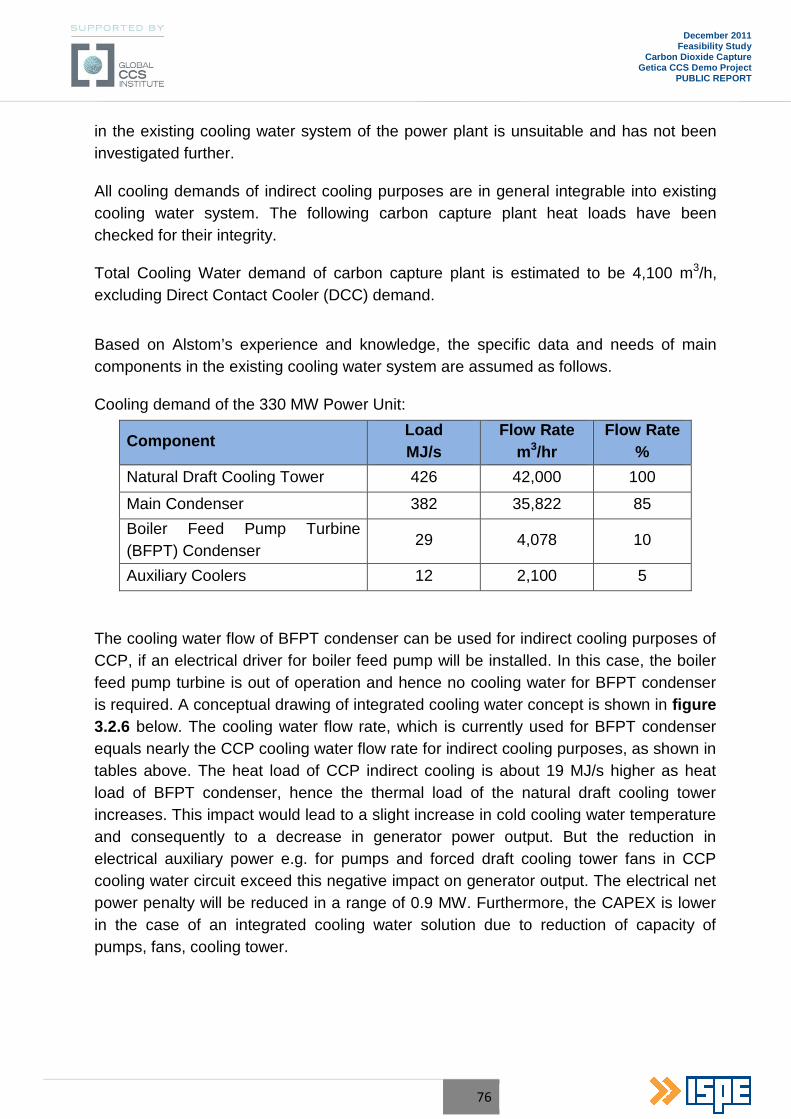
76
December 2011 Feasibility Study
Carbon Dioxide Capture Getica CCS Demo Project
PUBLIC REPORT
in the existing cooling water system of the power plant is unsuitable and has not been investigated further.
All cooling demands of indirect cooling purposes are in general integrable into existing cooling water system. The following carbon capture plant heat loads have been checked for their integrity.
Total Cooling Water demand of carbon capture plant is estimated to be 4,100 m3/h, excluding Direct Contact Cooler (DCC) demand.
Based on Alstom’s experience and knowledge, the specific data and needs of main components in the existing cooling water system are assumed as follows.
Cooling demand of the 330 MW Power Unit:
Component Load MJ/s
Flow Rate m3/hr
Flow Rate %
Natural Draft Cooling Tower 426 42,000 100
Main Condenser 382 35,822 85
Boiler Feed Pump Turbine (BFPT) Condenser
29 4,078 10
Auxiliary Coolers 12 2,100 5
The cooling water flow of BFPT condenser can be used for indirect cooling purposes of CCP, if an electrical driver for boiler feed pump will be installed. In this case, the boiler feed pump turbine is out of operation and hence no cooling water for BFPT condenser is required. A conceptual drawing of integrated cooling water concept is shown in figure 3.2.6 below. The cooling water flow rate, which is currently used for BFPT condenser equals nearly the CCP cooling water flow rate for indirect cooling purposes, as shown in tables above. The heat load of CCP indirect cooling is about 19 MJ/s higher as heat load of BFPT condenser, hence the thermal load of the natural draft cooling tower increases. This impact would lead to a slight increase in cold cooling water temperature and consequently to a decrease in generator power output. But the reduction in electrical auxiliary power e.g. for pumps and forced draft cooling tower fans in CCP cooling water circuit exceed this negative impact on generator output. The electrical net power penalty will be reduced in a range of 0.9 MW. Furthermore, the CAPEX is lower in the case of an integrated cooling water solution due to reduction of capacity of pumps, fans, cooling tower.
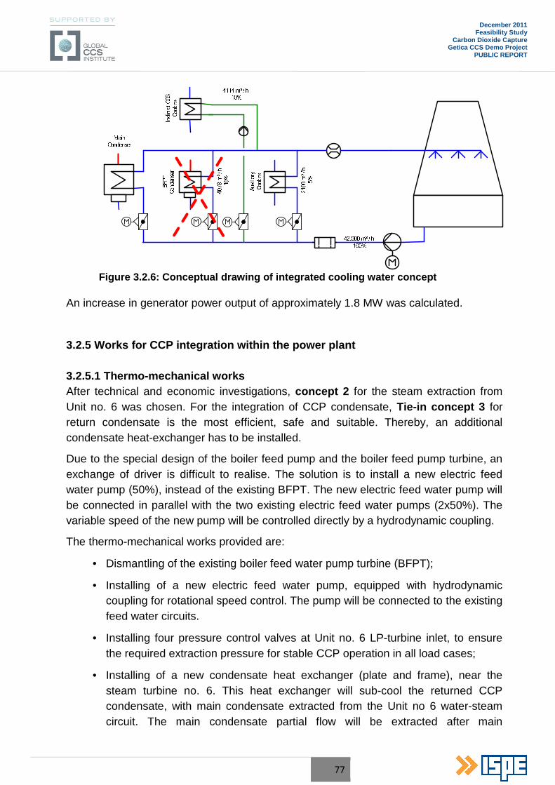
77
December 2011 Feasibility Study
Carbon Dioxide Capture Getica CCS Demo Project
PUBLIC REPORT
Figure 3.2.6 : Conceptual drawing of integrated cooling water concept
An increase in generator power output of approximately 1.8 MW was calculated.
3.2.5 Works for CCP integration within the power plant 3.2.5.1 Thermo-mechanical works After technical and economic investigations, concept 2 for the steam extraction from Unit no. 6 was chosen. For the integration of CCP condensate, Tie-in concept 3 for return condensate is the most efficient, safe and suitable. Thereby, an additional condensate heat-exchanger has to be installed.
Due to the special design of the boiler feed pump and the boiler feed pump turbine, an exchange of driver is difficult to realise. The solution is to install a new electric feed water pump (50%), instead of the existing BFPT. The new electric feed water pump will be connected in parallel with the two existing electric feed water pumps (2x50%). The variable speed of the new pump will be controlled directly by a hydrodynamic coupling.
The thermo-mechanical works provided are:
• Dismantling of the existing boiler feed water pump turbine (BFPT);
• Installing of a new electric feed water pump, equipped with hydrodynamic coupling for rotational speed control. The pump will be connected to the existing feed water circuits.
• Installing four pressure control valves at Unit no. 6 LP-turbine inlet, to ensure the required extraction pressure for stable CCP operation in all load cases;
• Installing of a new condensate heat exchanger (plate and frame), near the steam turbine no. 6. This heat exchanger will sub-cool the returned CCP condensate, with main condensate extracted from the Unit no 6 water-steam circuit. The main condensate partial flow will be extracted after main

78
December 2011 Feasibility Study
Carbon Dioxide Capture Getica CCS Demo Project
PUBLIC REPORT
condensate pump and will be integrated into the main condensate system between LP-preheater no.2 and LP-preheater no.3.
• Installing IP steam circuit from Unit 6 to the CCP;
• Installing LP steam circuit from Unit 6 to the CCP;
• Installing return condensate circuit from CCP to Unit no. 6 condenser;
3.2.5.2 Make-up Water Make up water is required for the cooling tower and the evaporative condenser. For the cooling tower and evaporative condenser clarified water, supplied from Turceni PP Water Treatment Plant is used. 3.2.5.3 Electric Works The consumers afferent to the CCP are in the same category as the electrical consumers of the Unit no.6.
Therefore, during normal operation, the CCP will be powered from the Unit no. 6 internal auxiliary services. The stand-by powering will be made from the general services.
Currently, Unit no. 6 is endowed with two auxiliaries transformers of 25MVA - 24/6.3kV which ensure the powering of the Unit auxiliaries. In order to ensure the necessary consumption for WFGD one of the two auxiliaries transformers will be replace with one of 40MVA-24/6.3kV.
In order to ensure the necessary consumption for the CCP, assessed to about 63MW, it is necessary to increase the ensured power for the supply of Unit auxiliaries, the two transformers mentioned above not being able to undertake the whole electrical consumption required by the CCP.
The main power supply “in fork” through a new internal service power transformer 24/10kV, rated power 63 (80) MVA of two bars medium voltage sections and the stand-by power supply through a general services also new power transformer 110/10kV, rated power 63 (80) MVA.
A longitudinal coupling between the two bars sections of CCP medium voltage will be foreseen. If one of the medium voltage power circuit breakers becomes unavailable, the afferent bar consumers can be supplied from the stand-by feeder, by closing the coupling. The procedure is similar when the two medium voltage sections of the CCP will be supplied from general services.
The electrical system for CCP will have new 10kV, 0.4kV and DC substations which will be based on modern and reliable technical solutions ensuring a high safety level and operation continuity and offer great flexibility.
79
December 2011 Feasibility Study
Carbon Dioxide Capture Getica CCS Demo Project
PUBLIC REPORT
The CCP 10kV substation will consist of two bus-bars sections with a longitudinal coupling.
Regarding changes in the Unit no. 6 due to CCP, these are due mainly to replacing the boiler feed pump turbine with an electric feed water pump with a 50% rate. Its electricity supply will come from the existing services, the reserve power provided by two existing transformers 24/6.3kV own existing services 25MVA respectively 40MVA (taking into account feeding "the fork" on both sections 6BA, 6BB internal services bars). In principle, the three electric feed water pumps 50% power would not work simultaneously.
3.2.5.4 Control system
To integrate the CCP in the power plant control system the following works are needed:
• Unit no. 6 DCS hardware and software extending for controlling the steam and condensate circuit connecting the CCP and the Unit no. 6, Low Pressure Turbine inlet steam flow control and installing the new feed water pump – FWTP no. 3;
• Dismantling works for the actual BFTP and cables;
• New flow, pressure and temperature measuring instruments for measuring the parameters on steam and condensate circuits connecting the CCP and the Unit no. 6 belonging to the new feed water pump – FWTP no. 3;
• Power Supply for shut-off valves, control valves, solenoid valves installed on the steam and condensate circuits connecting the CCP and the Unit 6 belonging to the new feed water pump – FWTP no. 3;
• Measurement and control cables, mounting materials.
3.2.5.5 Drinking Water, Fire fighting Water Supply and Sewage Systems
The drinking water, fire fighting water supply, the domestic waste water and meteoric sewerage will be provided through connection with the water and sewerage networks existing within Turceni PP second development area.
80
December 2011 Feasibility Study
Carbon Dioxide Capture Getica CCS Demo Project
PUBLIC REPORT
3.3 Preliminary environmental impact assessment
3.3.1 Legislation framework
Environmental protection is a major objective meant to lead to the sustainable development of the society, based on strategic principles and elements established by the legislation in force.
Environmental protection is an important criterion in the investment decision, because it is necessary to respect the environmental laws, which may lead to major economic effects.
The implementation of commercial scale CCS projects represents a new challenge to the existing regulatory framework, which has to be improved in order to allow the development of the projects during the construction and operational phases.
The present investment consists in implementation of a CO2 capture installation for Turceni PP – lignite Unit no. 6, based on Alstom’s Chilled Ammonia Process (CAP) , which will lead to a positive impact on climate change due to reduction of CO2 emissions.
The environmental impact has to be analysed in compliance with the legislation in force in Romania, harmonized with the EU Directives and with the recommendations related to environmental protection.
Generally for such an investment, the environmental provisions and regulations established by legislation in force at national level, which have to be observed are:
• GEO no. 164/2008 for modification and completion of GEO no. 195/2005 related to environmental protection, approved by Law no. 265/2006;
• GD no. 445/2009 on the assessment of the impact on the environment of certain public and private projects;
• Order no. 135/2010 for the approval of the environmental impact assessment procedure for public and private projects;
• Order no. 863/2002 for the approval of the methodological guidelines applicable to the framework procedure for the environmental impact assessment;
• GEO no. 152/2005, concerning integrated pollution prevention and control, modified by GEO no. 40/2010 (approved by Law no. 205/2010);
• Law no. 655/2001, which follows the prevention, elimination, limitation and improvement of air quality, in scope to avoid the negative effects on human health and environment, to assure that international legal norm are adhered to and UE regulations are taken into consideration (Atmosphere Protection);
81
December 2011 Feasibility Study
Carbon Dioxide Capture Getica CCS Demo Project
PUBLIC REPORT
• GD 440/2010 concerning the establishment of measures to limit air emissions of certain pollutants from large combustion plants;
• Order no. 592/2002 to approve Norm that establish the limit values, the threshold values and criteria and evaluation methods of sulphur dioxide, nitrogen dioxide and monoxide, particulate matters (PM10 and PM2,5), lead, benzene, carbon monoxide carbon and ozone in surrounding air, modified and completed by Order no. 27/2007;
• GEO no. 154/2008, which modify GEO no. 57/2007 related to the regime of the protected natural area, conservation of natural habitats, flora and wildlife and Law no. 407/2006 for hunting and cinegetic fund protection;
• GD no. 780/2006 establishing a scheme for greenhouse gas emissions allowances trading, amendment and completed by GD no. 133/2010 and GD no. 339/2010;
• Decision 2007/589/EC establishing guidelines for the monitoring and reporting of GHG emissions pursuant to Directive 2003/87/EC of the European Parliament and of the Council;
• Law no. 107/1996, with modification and completions of Law no. 310/2004 and Law no. 112/2006 (Water Law);
• GD no. 188/2002 which approves some norms related to the condition of the waste water discharged into the aquatic environment, modified and completed by GD no. 325/2005 and GD no. 210/2007;
• GEO no. 78/2000, related to the waste management, approved by Law no. 426/2001, modified by GEO no. 61/2006 and approved by Law no. 27/2007;
• GD no. 856/2002, related to the evidence of the waste management and for approval of the list with types of wastes, including hazardous, modified and completed by GD no. 210/2007;
• GD no. 235/2007 – regarding the waste oils management;
• Standard no. 10009/1989 – Urban Acoustic;
• Law no. 307/2006 regarding protection and fire fighting;
• Law no. 319/2006 concerning the labour security and health and the general labour protection norms.
The specific EU and national legislation which has to be observed for implementation of the CAP Plant at the retrofitted Unit no. 6 in Turceni PP are the following:
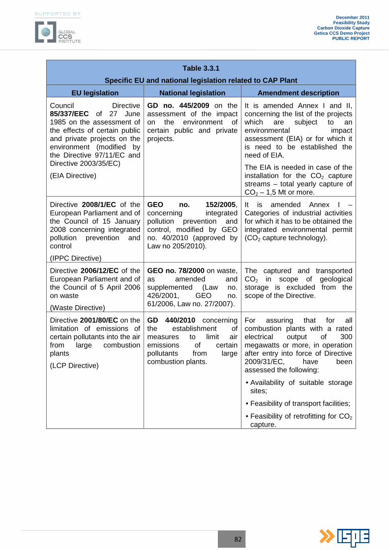
82
December 2011 Feasibility Study
Carbon Dioxide Capture Getica CCS Demo Project
PUBLIC REPORT
Table 3.3.1
Specific EU and national legislation related to CAP Plant
EU legislation National legislation Amendment description
Council Directive 85/337/EEC of 27 June 1985 on the assessment of the effects of certain public and private projects on the environment (modified by the Directive 97/11/EC and Directive 2003/35/EC)
(EIA Directive)
GD no. 445/2009 on the assessment of the impact on the environment of certain public and private projects.
It is amended Annex I and II, concerning the list of the projects which are subject to an environmental impact assessment (EIA) or for which it is need to be established the need of EIA.
The EIA is needed in case of the installation for the CO2 capture streams – total yearly capture of CO2 – 1,5 Mt or more.
Directive 2008/1/EC of the European Parliament and of the Council of 15 January 2008 concerning integrated pollution prevention and control
(IPPC Directive)
GEO no. 152/2005 , concerning integrated pollution prevention and control, modified by GEO no. 40/2010 (approved by Law no 205/2010).
It is amended Annex I – Categories of industrial activities for which it has to be obtained the integrated environmental permit (CO2 capture technology).
Directive 2006/12/EC of the European Parliament and of the Council of 5 April 2006 on waste
(Waste Directive)
GEO no. 78/2000 on waste, as amended and supplemented (Law no. 426/2001, GEO no. 61/2006, Law no. 27/2007).
The captured and transported CO2 in scope of geological storage is excluded from the scope of the Directive.
Directive 2001/80/EC on the limitation of emissions of certain pollutants into the air from large combustion plants
(LCP Directive)
GD 440/2010 concerning the establishment of measures to limit air emissions of certain pollutants from large combustion plants.
For assuring that for all combustion plants with a rated electrical output of 300 megawatts or more, in operation after entry into force of Directive 2009/31/EC, have been assessed the following:
• Availability of suitable storage sites;
• Feasibility of transport facilities;
• Feasibility of retrofitting for CO2 capture.
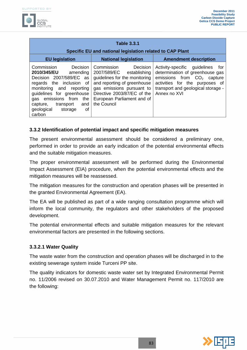
83
December 2011 Feasibility Study
Carbon Dioxide Capture Getica CCS Demo Project
PUBLIC REPORT
Table 3.3.1
Specific EU and national legislation related to CAP Plant
EU legislation National legislation Amendment description
Commission Decision 2010/345/EU amending Decision 2007/589/EC as regards the inclusion of monitoring and reporting guidelines for greenhouse gas emissions from the capture, transport and geological storage of carbon
Commission Decision 2007/589/EC establishing guidelines for the monitoring and reporting of greenhouse gas emissions pursuant to Directive 2003/87/EC of the European Parliament and of the Council
Activity-specific guidelines for determination of greenhouse gas emissions from CO2 capture activities for the purposes of transport and geological storage - Annex no XVI
3.3.2 Identification of potential impact and specific mitigation measures
The present environmental assessment should be considered a preliminary one, performed in order to provide an early indication of the potential environmental effects and the suitable mitigation measures.
The proper environmental assessment will be performed during the Environmental Impact Assessment (EIA) procedure, when the potential environmental effects and the mitigation measures will be reassessed.
The mitigation measures for the construction and operation phases will be presented in the granted Environmental Agreement (EA).
The EA will be published as part of a wide ranging consultation programme which will inform the local community, the regulators and other stakeholders of the proposed development.
The potential environmental effects and suitable mitigation measures for the relevant environmental factors are presented in the following sections.
3.3.2.1 Water Quality
The waste water from the construction and operation phases will be discharged in to the existing sewerage system inside Turceni PP site.
The quality indicators for domestic waste water set by Integrated Environmental Permit no. 11/2006 revised on 30.07.2010 and Water Management Permit no. 117/2010 are the following:
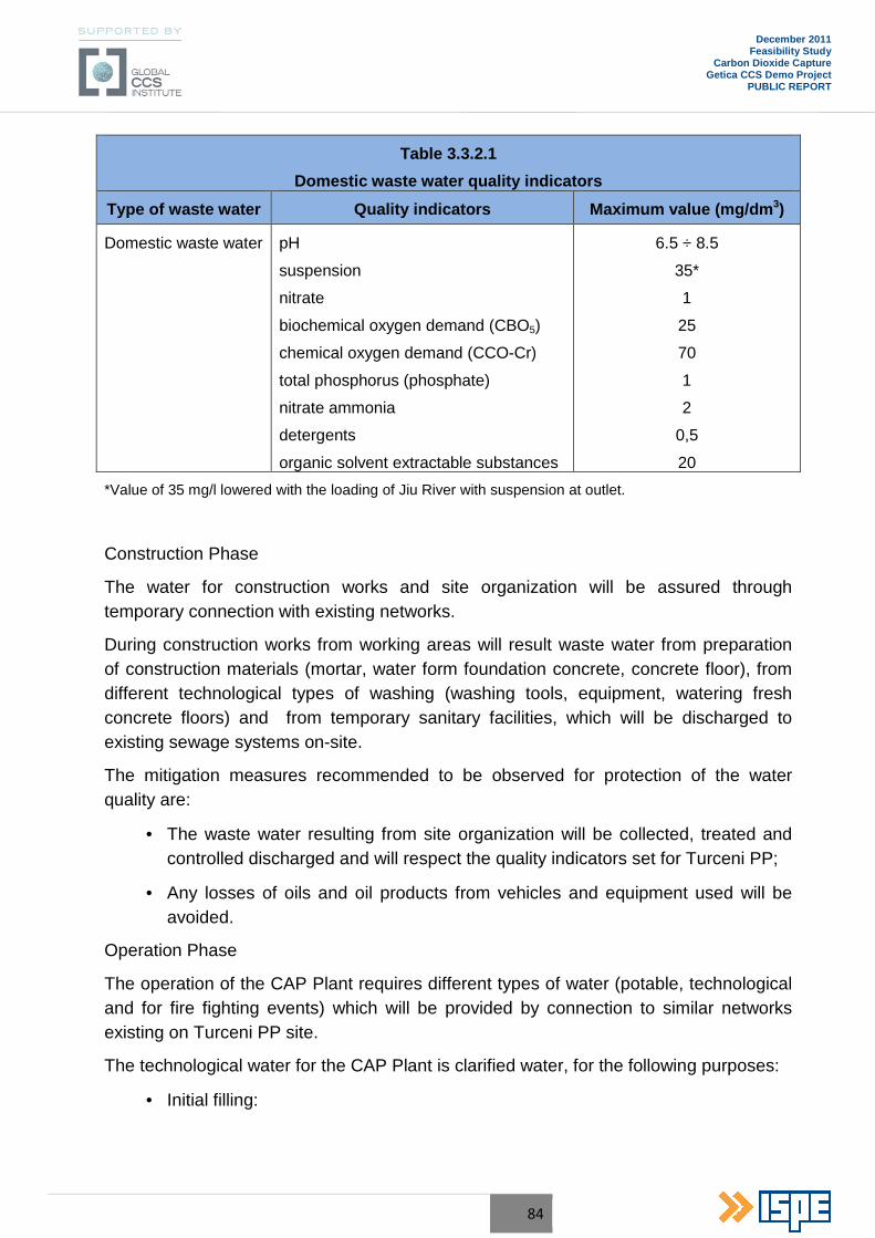
84
December 2011 Feasibility Study
Carbon Dioxide Capture Getica CCS Demo Project
PUBLIC REPORT
Table 3.3.2.1
Domestic waste water quality indicators
Type of waste water Quality indicators Maximum value (mg/dm 3)
Domestic waste water pH
suspension
nitrate
biochemical oxygen demand (CBO5)
chemical oxygen demand (CCO-Cr)
total phosphorus (phosphate)
nitrate ammonia
detergents
organic solvent extractable substances
6.5 ÷ 8.5
35*
1
25
70
1
2
0,5
20
*Value of 35 mg/l lowered with the loading of Jiu River with suspension at outlet.
Construction Phase
The water for construction works and site organization will be assured through temporary connection with existing networks.
During construction works from working areas will result waste water from preparation of construction materials (mortar, water form foundation concrete, concrete floor), from different technological types of washing (washing tools, equipment, watering fresh concrete floors) and from temporary sanitary facilities, which will be discharged to existing sewage systems on-site.
The mitigation measures recommended to be observed for protection of the water quality are:
• The waste water resulting from site organization will be collected, treated and controlled discharged and will respect the quality indicators set for Turceni PP;
• Any losses of oils and oil products from vehicles and equipment used will be avoided.
Operation Phase
The operation of the CAP Plant requires different types of water (potable, technological and for fire fighting events) which will be provided by connection to similar networks existing on Turceni PP site.
The technological water for the CAP Plant is clarified water, for the following purposes:
• Initial filling:
85
December 2011 Feasibility Study
Carbon Dioxide Capture Getica CCS Demo Project
PUBLIC REPORT
o Cooling water system closed-type, consisting in: cooling tower, pumps station and pipelines;
o Circulation water system for evaporative condenser.
• Make-up water for the closed type cooling circuit and evaporative condenser (part of refrigeration unit).
Make-up water for the closed type cooling circuit will be mechanical filtered water (clarified water) from the existing Chemical Water Treatment Plant – Water pre-treatment installation.
The potable water (15 m3/day peak consumption) and fire fighting water for the CAP Plant will be provided by connection with similar networks existing on Turceni PP site.
Due to the closed loop water, the potential contaminated waste streams and the need of waste water treatment are eliminated.
The waste water (domestic and pluvial) will be discharged through similar waste water networks on Turceni PP site. The quality of waste water will meet the indicators set by Turceni PP IPPC Permit no. 11/2006 (revised on 30.07.2010) and Water Management Permit no. 117/2010.
3.3.2.2 Air Quality
Construction Phase
For the CAP Plant, during the construction phase, the potential sources of air pollution may be:
• The pollutant substances released by vehicles and non-road equipment;
• The manipulation of powdery materials for preparing the construction materials;
• The pollutant substances from specific construction activities.
The mitigation measures recommended to be observed for protection of the air quality are:
• Using the vehicles and non-road equipment with low emissions;
• For avoiding dust emissions, the soil and the access roads (in dry periods) will be sprayed during construction works and the works which may generate dust emissions during windy periods will be avoided.
Operation Phase
Several retrofitting works are ongoing at the Turceni PP Unit no. 6 for complying with provisions set by the legislation, this includes:
• LCP Directive (Directive 2001/80/EC) and Industrial Emissions Directive (Directive 2010/75/EU), due to implementation of the wet flue gases
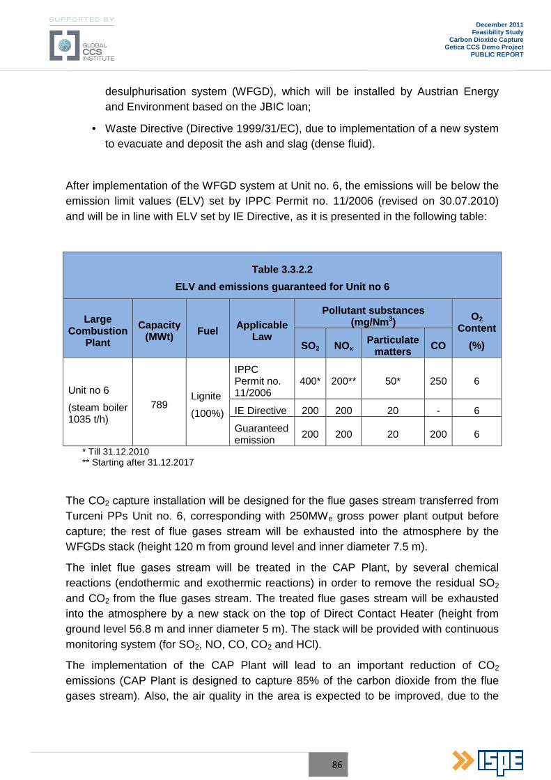
86
December 2011 Feasibility Study
Carbon Dioxide Capture Getica CCS Demo Project
PUBLIC REPORT
desulphurisation system (WFGD), which will be installed by Austrian Energy and Environment based on the JBIC loan;
• Waste Directive (Directive 1999/31/EC), due to implementation of a new system to evacuate and deposit the ash and slag (dense fluid).
After implementation of the WFGD system at Unit no. 6, the emissions will be below the emission limit values (ELV) set by IPPC Permit no. 11/2006 (revised on 30.07.2010) and will be in line with ELV set by IE Directive, as it is presented in the following table:
Table 3.3.2.2
ELV and emissions guaranteed for Unit no 6
Large Combustion
Plant
Capacity (MWt) Fuel Applicable
Law
Pollutant substances (mg/Nm 3) O2
Content
(%) SO2 NOx Particulate
matters CO
Unit no 6
(steam boiler 1035 t/h)
789 Lignite
(100%)
IPPC Permit no. 11/2006
400* 200** 50* 250 6
IE Directive 200 200 20 - 6
Guaranteed emission 200 200 20 200 6
* Till 31.12.2010 ** Starting after 31.12.2017
The CO2 capture installation will be designed for the flue gases stream transferred from Turceni PPs Unit no. 6, corresponding with 250MWe gross power plant output before capture; the rest of flue gases stream will be exhausted into the atmosphere by the WFGDs stack (height 120 m from ground level and inner diameter 7.5 m).
The inlet flue gases stream will be treated in the CAP Plant, by several chemical reactions (endothermic and exothermic reactions) in order to remove the residual SO2 and CO2 from the flue gases stream. The treated flue gases stream will be exhausted into the atmosphere by a new stack on the top of Direct Contact Heater (height from ground level 56.8 m and inner diameter 5 m). The stack will be provided with continuous monitoring system (for SO2, NO, CO, CO2 and HCl).
The implementation of the CAP Plant will lead to an important reduction of CO2
emissions (CAP Plant is designed to capture 85% of the carbon dioxide from the flue gases stream). Also, the air quality in the area is expected to be improved, due to the
87
December 2011 Feasibility Study
Carbon Dioxide Capture Getica CCS Demo Project
PUBLIC REPORT
reduction of SO2 and dust emissions in the flue gases stream, as a result of processes in the CAP Plant.
The monitoring of CO2 emissions will be in line with provisions set by Commission Decision 2010/345/EU amending Decision 2007/589/EC, Annex no XVI – “Activity-specific guidelines for determination of greenhouse gas emissions from CO2 capture activities for the purposes of transport and geological storage”, which involve determination of the amount of CO2 transferred to and from CAP Plant by means of continuous emissions monitoring systems (CEMS) with a total uncertainty of the overall emissions or CO2 flow over the reporting period of less than ± 2.5%.
The air quality impact will be assessed for the relevant pollutant substances, by comparing the hourly, daily and annual concentrations with the limit values for protection of human health and vegetation.
The modelling of the dispersion of pollutant substances into the air will be performed with a mathematic model suitable for industrial activities – ARIA Impact ; the site specific meteorological conditions and all sources of pollutant emissions in the analysed area will be considered. This task will be performed during the EIA procedure.
3.3.2.3 Noise and vibrations
Construction Phase
The mitigation measures recommended to be observed for respecting the noise level are:
• Vehicles and equipment with low noise level will be used;
• The operations which may generate noise will be performed indoors (if possible) and during daytime.
Operation Phase
In operation, the main sources of noise from the CAP Plant are equipment which have moving sub-sets (pumps – especially large ones), fans and compressors. Noise reduction shall especially be carried out by mounting this equipment inside certain buildings.
The level of noise generated by equipment shall observe the provisions set by the Law no. 319/2006 concerning the Labour Security and Health. The maximum accepted limit for noise at work places is 87 dB(A) at 1 m from equipment (with precaution measures when the value of 85dB(A) is reached).
The noise level at the power plant boundary will respect the maximum values provided by STAS no. 10009/1988 – Urban Acoustic, of 65 dB(A).
88
December 2011 Feasibility Study
Carbon Dioxide Capture Getica CCS Demo Project
PUBLIC REPORT
3.3.2.4 Ground and underground protection
During the construction works, ground areas will be affected by the site organization and by the new specific CAP building constructions. As the works are carried out within the existing Turceni PP site, new ground surfaces will not be affected.
The potential sources of pollution may be: waste, construction materials, etc.
The mitigation measures which have to be observed for protecting the soil and underground are:
• Minimum area for site organization;
• The waste from construction works will be temporarily stored in proper areas;
• The construction materials will be stored in the contractor’s material stores; the transportation to the site will be provided by lorry, using the existing roads in the area;
• Any losses of construction materials during transport and handling will be avoided.
After the works’ finalization, the ground surfaces occupied with the site organization shall be brought back to its initial state.
Under normal operation conditions, no soil contamination is expected due to the following measures undertaken since the designing phase:
• Installations and equipment will be placed on monolith concrete foundations;
• A proper management of chemical substances (suitable storage and dosing systems) will be provided.
3.3.2.5 Terrestrial and aquatic ecosystems protection
The CAP Plant will be located in the existing industrial area (Turceni PP site) and will not influence the terrestrial and aquatic ecosystems in the area.
The nearby NATURA 2000 site – Special Areas of Conservation – is ROSCI0045 “Coridorul Jiului”, which has a total area of 71,394 hectares and includes different types of ecosystems such as: rivers, swamps, pastures, vineyards and orchards, and species of flora and fauna.
The nearest distances between Turceni PP and ROSCI0045 “Coridorul Jiului” are around 2 km (North direction and South-East direction) and 2.5 km (East direction).
The map with location of the Turceni PP, the CO2 transport pipeline routes, the geological storage zones (no. 1 and no. 5) and the NATURA 2000 sites in the analysed area, is presented in Annex H.
89
December 2011 Feasibility Study
Carbon Dioxide Capture Getica CCS Demo Project
PUBLIC REPORT
3.3.2.6 Human activities and other objective for public interest
The CAP Plant will be located in the Turceni PP site, so the investment will be in progress inside an existing operating industrial area.
The construction works will be properly organized so as to not disturb any other activities in the area. The nearby populated areas are presented in General Site Layout. Inside the plant will be provided appropriate measures for fire fighting events in order to avoid any incidents which may lead to human or environmental risks (explosion, fire, etc.); all plant’s objects will be provided with access for fire fighting intervention.
3.3.2.7 Waste management
Waste resulted during the construction works and the operation of the CAP Plant (metallic materials, soil, insulating materials, etc.) shall be collected selectively, temporarily stored in a restricted area (concrete platforms or special storage area) and evacuated according to the provisions set by the GEO no. 78/2000 related to waste management (with further modification and completion).
Construction phase
For the CO2 Capture, the waste resulted during construction works (metals, plastic, soil, etc.) will be selectively collected, temporarily stored in special areas and evacuated by authorised companies.
The metallic waste shall be temporarily stored on platforms and evacuated by authorized companies, in conformity with GEO no. 16/2001.
Soil resulted from construction works will be reused in other area or will be gradually evacuated to a non-recyclable deposit, as agreed with local authorities.
The mitigation measures which have to be observed for protection of the environment are:
• Use of modern construction solutions with low waste generation;
• Proper management of the construction and domestic wastes.
Operation phase
The types of waste generated by the CAP Plant mainly remain similar with those generated by the existing power plant and will be managed under current practices.
Apart from these types of waste, in the CAP Plant a by-product consisting in liquid ammonium sulphate stream will be obtained, which has commercial value and can be used as a fertilizer. This by-product will be temporarily stored on site in a storage tank for about 10 days of continuous operation.
90
December 2011 Feasibility Study
Carbon Dioxide Capture Getica CCS Demo Project
PUBLIC REPORT
The domestic waste will be collected, temporarily stored in containers and picked up periodically by a specialised company.
3.3.2.8 Dangerous and toxic waste management
The operation of the CAP Plant involves the use of the following chemical substances:
• Anhydrous ammonia (100%), as a reagent for reducing the SO2 emissions from the inlet flue gases in the CAP Plant. The consumption of reagent is rather low, due to reversible nature of CAP reactions (which allows the regeneration of the solution).
• Sulphuric acid (93%), injected for controlling the concentration of ammonia in the treated flue gases (bellow 5ppm), by maintaining a low pH level in the circulating water loop.
For these two types of chemical substances, suitable storage and dosing systems are provided.
The management of waste oils will be done by authorised companies, according to provisions set by GD no. 235/2007.
3.3.2.9 Site rehabilitation works
The CAP Plant will be located in Turceni PP site and the investment will be in progress inside an existing operating industrial area. The existing roads on Turceni PP site will be used during construction.
At the end of construction, all occupied area for site works will be restored to its original state.
The works’ executor will ensure the environmental protection and the labour protection conditions for the workers. The workers will be instructed to comply with labour protection norms, prevention and fire fighting norms, as well as those specific for construction and operation activities.
3.3.3 Consultation
In order to successfully implement a full chain CCS technology at the national level, social and environmental risks have to be addressed prior to the formal permitting process.
Knowing the importance of engaging the public and stakeholders at an early stage of the Project and in order to identify and prioritize the environmental and social risks, in November 2010, the Ministry of Economy, Trade and the Business Environment
91
December 2011 Feasibility Study
Carbon Dioxide Capture Getica CCS Demo Project
PUBLIC REPORT
together with GeoEcoMar and ISPE (as members of the Technical Consortium) organized the first communication event in Targu Jiu, Gorj County.
Key topics addressed were related to: the Energy and Climate Change policies and legislation (including specific actions at EU and national levels), the CCS national R&D programs, the CCS technologies (including CO2 geological storage and monitoring methods) and the Getica CCS Demo Project. CCS was presented as a suitable measure, which together with the RES portfolio and energy efficiency measures, will allow achieving the EU targets related to reduction of GHG emissions.
Experts had an open dialog with the targeted audience: policy makers, regulatory authorities, local and regional administrations, the industry, R&D, academics, and NGOs. An event kit was prepared including general brochures about CCS (in Romanian) from ZEP, BRGM, the Bellona Foundation and the Getica CCS fact sheet.
The event was followed by an open debate where opinions were addressed by the community representatives to the experts and stakeholders, including:
• The willingness to receive and process information related to the impact of climate change and mitigation solutions;
• Interest for innovative low carbon technology associated risks, especially related to the technology safety of CO2 storage and injection;
• Concerns related to the sustainability of the CCS technology (social, economic and environmental);
• The need to secure a safe and healthy future environment for the generations to come.
The following event, “Open Door Event at Turceni Power Plant” will be organized on 14 April 2011, by Turceni Energy Complex (CE Turceni) together with ISPE (as a member of the Technical Consortium and CCS Project manager).
The aim of this event is to establish a communication channel between experts, officials, industries, the local community and media representatives to increase community understanding related to clean energy technologies, through public engagement and awareness.
Topics presented will be focused on policies and actions at EU and national levels for reducing the GHG emissions, viable technological solutions as a mix of energy efficiency, renewable and CCS, EU and international financing support, regional and international cooperation, and Getica CCS Demo Project development stage.
Besides this, even if it does not qualify as public consultation, the educational event for raising the knowledge level related to energy, climate change and mitigation solutions, addressed to children within the primary cycle from the Turceni Industrial School Group, on 14 March 2011, must be mentioned. More than 90 children and teachers have participated at the event, organized by CE Turceni and ISPE.
92
December 2011 Feasibility Study
Carbon Dioxide Capture Getica CCS Demo Project
PUBLIC REPORT
The children were excited to find out more about the environment and how they can help Earth to remain green and healthy; we had a pleasant surprise to find out that most of the children understood the greenhouse phenomena and heard about recycling, saving energy, wind power and hydro.
The following actions are planned:
• A drawing exhibition at Turceni PP with children’s creation related to the information transferred during the educational event;
• A voluntary action organized together with the children, such as planting trees in Turceni PP enclosure;
• Other educational events organized for the gymnasium and college cycles children.
3.4 Industrial Risk Management
3.4.1 Introduction
The following three steps are inherent in all hazards identification and risk assessment approaches:
Step 1: Identification of the hazard, based upon consideration of factors such as the physical and chemical properties of the fluids being handled, the arrangement of equipment, operating and maintenance procedures and processing conditions. External hazards such as mechanical impact and extreme environmental conditions, also need to be considered at this stage.
Hazard identification is the most important step in the risk management process, since a hazard that is not identified or fully recognized will not be effectively managed.
Hazard identification is the process of identifying and classifying credible and incredible hazards by cause, location, method of assessment, consequence, impact or any other grouping, with the objective of specifying failure cases, or starting conditions for events to be ranked with respect to their frequency, consequence and impact.
Step 2: Assessment of the risk arising from the hazards and consideration of its tolerability to personnel, the facility and the environment. This normally involves the identification of initiating events, identification of possible accident sequences, estimation of the probability of occurrence of accident sequences and assessment of the consequences. The acceptability of the estimated risk must then be judged based upon criteria appropriate to the particular situation.
Step 3: Elimination or reduction of the risk where this is deemed to be necessary. This involves identifying opportunities to reduce the probability and/or consequences of an accident.
93
December 2011 Feasibility Study
Carbon Dioxide Capture Getica CCS Demo Project
PUBLIC REPORT
METHODS TAKEN INTO CONSIDERATION AT THIS STAGE:
• One of the methods that have been considered appropriate by the scientific world is the SWIFT (“Structured What IF Technique”) analysis.
• Another studied method is the EVENT TREES ANALYSIS (ETA) , combined with the FAILURE TREES ANALYSIS (FTA) , having the following characteristics:
• The “CHECKLIST ”: based on a predetermined checklist, which values the previous experience and emphasizes the information related to similar cases;
• HAZOP (Hazard and Operability Study);
• FMEA (Fault Mode and Effect Analysis).
Neither of the previous methods could be fully applicable.
Probably the best results shall be obtained by a combination of them, performed by experienced analysts.
3.4.2 Management
The primary means of prevention is the use of appropriate standards for design and operation, the quality standards applied to design, construction and operation and the optimization of the pipeline routing for safety (as well as for other business drivers).
Effective management of the structural integrity of the system will include:
• Demonstrating applicability of design Codes and Standards used;
• Providing evidence of conformity to the design Codes and Standards;
• Determining normal operation and foreseeable extreme criteria;
• Demonstrating suitability of materials used;
• Demonstrating applicability of standards used;
• Providing evidence of conformity to the standards.
Good design is the most effective means of preventing CO2 releases.
This involves addressing issues such as:
• The need to minimize the frequency, rate and quantity of releases by, for example, reducing the number of release points and addressing causes of failure, and limiting the inventory available for release;
• Optimizing the pipeline route and the location and layout of any associated systems.
94
December 2011 Feasibility Study
Carbon Dioxide Capture Getica CCS Demo Project
PUBLIC REPORT
3.4.3 Mitigation Measures
The effective risk management plan has to include identification of plant incidents as well as mitigation measures implementation if reasonably practicable. Equipment provided and action taken should be based on the risk assessment.
All CCO operators must prepare adequate emergency plans for dealing with the consequences of possible major accidents and providing assistance with off-site mitigation action.
The CCP operator therefore has a duty to provide education for the people responsible for the development of the off-site plant as well as the people who have roles to play in the plan with regard to CO2, its characteristics and its dangers.
Risk management measures once identified must be maintained to deliver the defined level of performance that is required. To achieve this there should be a continuous management cycle of:
• Maintaining an understanding of the hazards and risk;
• Identifying the critical risk management measures;
• Defining the minimum level of performance from each critical element;
• Implementing a robust inspection, test and maintenance regime to keep the critical elements performing;
• Having a verification process to provide assurance that the critical elements are actually likely to deliver the defined level of performance;
• Having a review loop to ensure any changes in the risk profile or its management is identified and fed back into the cycle.
Sources of risks that should be considered:
1. Seismic conditions;
2. Perpetration human errors (during designing, construction, mounting, operation and maintenance) due to lack of experience;
3. Skip human errors due to lack of experience;
4. Failure rates of the equipment, pipeline and valves (for the considered pressure, temperature, section, length, diameter a.s.o.);
5. Type and direction of considered release;
6. Released jet diameter;
7. Vapour mass fraction in the release;
8. The dose-effect relationship for CO2.
95
December 2011 Feasibility Study
Carbon Dioxide Capture Getica CCS Demo Project
PUBLIC REPORT
The following, for example , have to be considered, with (conservative) frequency modification factors employed (until directly relevant CO2 experience is established):
• Design – Appropriateness of design codes and standards for CO2 service (e.g. designing for preventing propagating failures, for severe chilling etc.);
• Operation – Potential for blocking of a CO2 pipe with solid CO2 or for over-pressurising the CO2 pipe by an inappropriate re-starting process whenever the solid CO2 is accidentally present.
For CO2 pipes the following causes (as a minimum) should be adequately examined and measures put in place to prevent, or if this is not reasonably practicable, minimize the likelihood of occurrence:
• External loading (e.g. seismic);
• Internal loading (e.g. bends, two phase slugs, pits, debris etc.);
• Mechanical impacts (external);
• Corrosion – potential for high corrosion rates due to contaminants within CO2 stream (e.g. water, H2, O2, H2S etc.);
• Pressure deviation;
• Temperature deviation;
• Vibration;
• Incorrect equipment choice;
• Equipment failure during operation;
• Human error.
Personnel required to implement procedures should be competent to do so, adequately trained, and supervision and information about the hazards should be provided. Human factors issues should be identified and taken into account in the design of procedures and systems.
Normal and safe operating limits should be defined and safeguards (i.e. measures) against excursions from the design conditions put in place.
These limits should, as a minimum define acceptable limits for:
• Water;
• Other impurities (e.g. H2, NOx, SOx, H2S, CO, O2);
• Temperature;
• Pressure.
96
December 2011 Feasibility Study
Carbon Dioxide Capture Getica CCS Demo Project
PUBLIC REPORT
The effective management of water and other impurities will be critical for preventing potentially very rapid internal corrosion.
The depressurization of dense phase CO2 may, if not carefully controlled, result in a significant temperature drop of the inventory and containment envelope (e.g. equipment/pipe material).
Allowing the formation of solid CO 2 in a system is not desirable since:
• Solid CO2 at ambient pressure is -78°C and this would severe ly chill possibly leading to:
o Embrittlement and fracture;
o Damage to linings or coatings.
The following systems will require to be considered when specifying and designing the CO2 systems:
• Safety related control and protective systems;
• Process control systems (including back-ups);
• Safety instrumented systems;
• Loss of containment detection systems;
• Alarm systems;
• Automatic shutdown systems;
• Automatic pressure control or let-down systems.
For CO 2 detection, it should be taken into account that CO2 vapour is denser than air and will tend to sink down, slump and spread out over the ground and accumulate in low level areas.
Detection measures should be automatic with automatic transmission of information to an appropriate control point, where this is reasonably practicable. The potential failure mode of electronic devices when exposed to extreme chilling, as would be the case in the plume of a large dense phase CO2 release, needs to be considered.
For the CO 2 system control measures may include:
• Propagating crack arrestors;
• Emergency shutdown (ESD) system;
• Automatic isolation valves;
• Vents and drains;
• Emergency depressurization (blowdown) system.
97
December 2011 Feasibility Study
Carbon Dioxide Capture Getica CCS Demo Project
PUBLIC REPORT
For CO 2 service, the following should be considered within the design process:
• Appropriate elastomers should be selected for the CO2 duty;
• Appropriate lubrication should be selected for the CO2 duty;
• Should a valve fail to seal completely, the flow through the valve will lead to severe cooling on the downstream side with the potential for considerable solid CO2 build up (at -78°C);
• Re-pressurization of a system where there is dense phase CO2 on one side of a valve and sub-critical pressure on the other, will result in cooling and CO2 solidification. Re-pressurization of systems requires careful consideration;
• Depressurization of a dense phase CO2 inventory can start, if not carefully controlled, resulting in large amounts (potentially tonnes) of solid CO2 being deposited at the low points within the system.
CCS CO2 systems will need to be depressurized for operational reasons and potentially as part of a hazard management strategy (e.g. emergency blowdown) sometime during the lifecycle of the systems. In addition to situations where a controlled depressurization is undertaken, unplanned or inadvertent depressurization of dense phase CO2 inventories is also reasonably foreseeable (e.g. a loss of containment event occurs).
CO2 detection instrumentation should be properly chosen:
• CO2 is present in the air we breathe 0.037% and this may cause problems with instrumented detection because the ‘background CO2’ levels are so high;
• Secondly the cooling effects of a CO2 leak may have an adverse effect on the accuracy and operability of CO2 gas detection systems.
The risk assessment will be periodically updated.
For a correct risk assessment issuing it shall be settled a proper database.
Risk Register is presented in Annex I (confidential).
98
December 2011 Feasibility Study
Carbon Dioxide Capture Getica CCS Demo Project
PUBLIC REPORT
3.5 Personnel for CCP Operation
Operators
The operator’s duties and responsibilities are as follows:
• Perform plant start-up, shutdown and operation of the pilot plant by manipulating the control room operator interface and by adjusting manual valves and switches in the field;
• Continuously monitor the process operating conditions at the control room operator interface;
• Be aware of trends and correct abnormal conditions as directed;
• Manually record routine activities and major events in the logbook;
• Compile all relevant and recorded plant historical data in electronic format for future analysis;
• Conduct periodic inspection tours of the pilot plant;
• Gather liquid samples for analysis.
A detailed listing of all operator activities is listed below.
1. Procedures
A. Revise operating procedures as required by actual operations.
i. Preoperational checks
ii. Start-up procedure
iii. Routine operations
iv. Shutdown procedure
a) Normal
b) Emergency
v. Equipment clean out
vi. Demolition
2. Equipment
A. Analyse equipment failures to improve process reliability.
B. Study and optimize individual unit operations equipment for increased performance.
C. Control inventory of consumables and long-lead failure items to reduce operation downtime.
99
December 2011 Feasibility Study
Carbon Dioxide Capture Getica CCS Demo Project
PUBLIC REPORT
3. Operating Conditions
A. Analyse process operating conditions during failure for improved operational reliability.
B. Improve process operating conditions to increase performance capabilities.
4. Test Plans
A. Baseline column hydraulics testing.
B. Operate process to accumulate long term performance data.
C. Revise process flow diagram to incorporate automation and improved process controls.
5. Liquid Analysis
A. Take liquid samples for analysis.
B. Perform liquid sample analysis in-house or alternatively send it out to an external agency.
6. Gas Analysis
A. Operate gas sampling system to determine current performance.
B. Assist contractors with isokinetic sampling of flue gas streams.
7. Routine Operations
A. Maintain process surveillance during operation.
B. Respond appropriately to control system alarms and warnings.
C. Purchase consumable chemicals as required to sustain process operations.
D. Schedule routine waste shipments to maintain process operations.
8. Equipment Maintenance
A. Schedule and manage maintenance of equipment and repairs.
9. Safety
A. Maintain and improve plant safety.
B. Procurement and inventory of required safety equipment
10. Environmental Awareness
A. Maintain environmental awareness.
B. Reduce plant environmental impact.
100
December 2011 Feasibility Study
Carbon Dioxide Capture Getica CCS Demo Project
PUBLIC REPORT
11. Data Analysis
A. Compare operating data with plant design data.
Shift Supervisor and Operating Personnel
For plant operation 1 (one) shift supervisor will be assigned to each shift consisting of 2 (two) board operators and 1 (one) field operator to cover the described duties.
The shift supervisor will perform extra duties to help maintain the process as outlined above for the process operators.
Analytical Chemist
The analytical chemist will perform the following functions for the plant.
• Periodically review the plant operating conditions and trends;
• Analyse liquid samples to verify mass and energy balance calculations and to adjust operating conditions;
• Request plant operating conditions adjustments based on analytical results obtained.
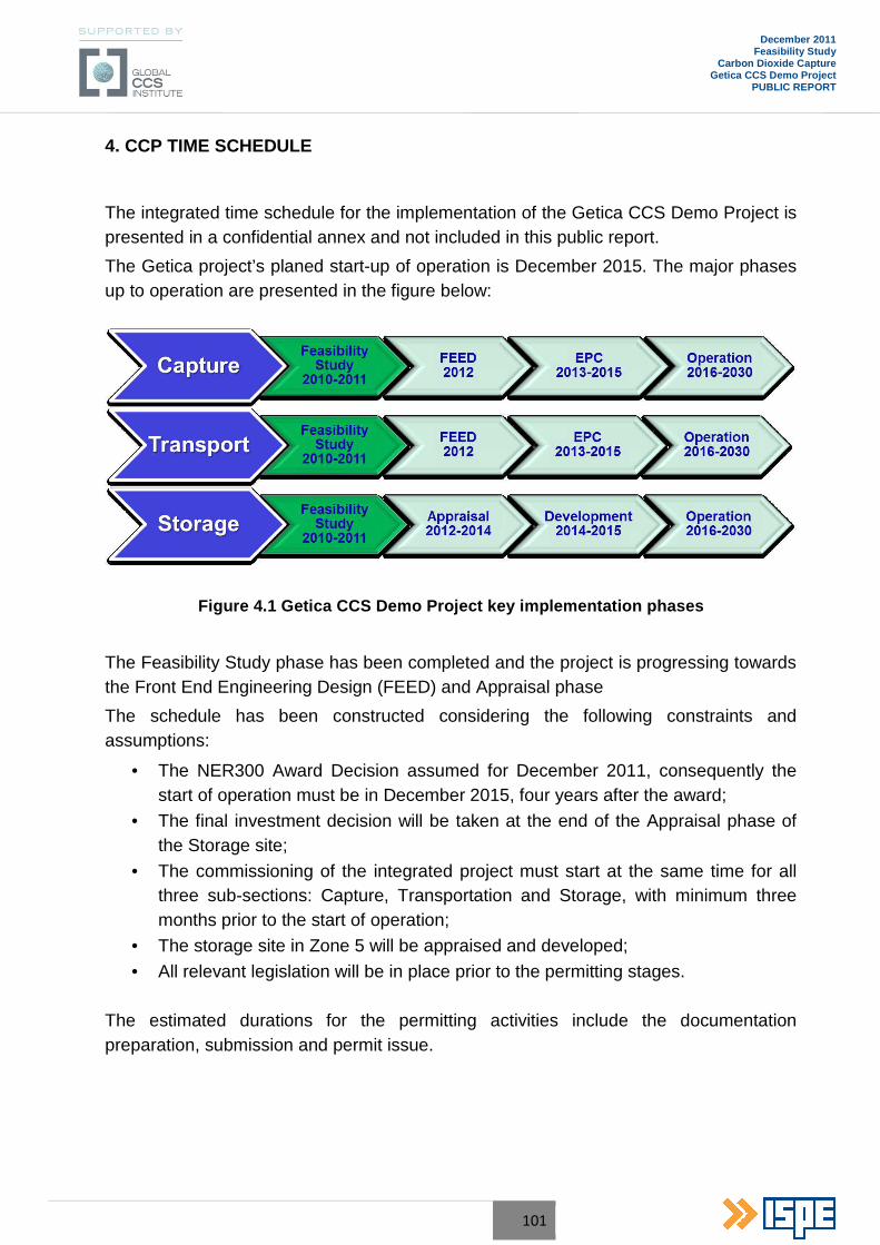
101
December 2011 Feasibility Study
Carbon Dioxide Capture Getica CCS Demo Project
PUBLIC REPORT
4. CCP TIME SCHEDULE
The integrated time schedule for the implementation of the Getica CCS Demo Project is presented in a confidential annex and not included in this public report.
The Getica project’s planed start-up of operation is December 2015. The major phases up to operation are presented in the figure below:
Figure 4.1 Getica CCS Demo Project key implementation phases
The Feasibility Study phase has been completed and the project is progressing towards the Front End Engineering Design (FEED) and Appraisal phase
The schedule has been constructed considering the following constraints and assumptions:
• The NER300 Award Decision assumed for December 2011, consequently the start of operation must be in December 2015, four years after the award;
• The final investment decision will be taken at the end of the Appraisal phase of the Storage site;
• The commissioning of the integrated project must start at the same time for all three sub-sections: Capture, Transportation and Storage, with minimum three months prior to the start of operation;
• The storage site in Zone 5 will be appraised and developed;
• All relevant legislation will be in place prior to the permitting stages.
The estimated durations for the permitting activities include the documentation preparation, submission and permit issue.
102
December 2011 Feasibility Study
Carbon Dioxide Capture Getica CCS Demo Project
PUBLIC REPORT
5. COST ESTIMATE
Investment costs include:
• Capital expenditure (CAPEX) for Carbon Capture Plant (CCP) and integration with the existing installations of Turceni Power Plant;
• Quota for public awareness, communication and knowledge sharing.
Investment costs estimation includes: capital equipment, sites infrastructure, studies, engineering and design, installation and commissioning, permits, taxes, project management.
CAPEX for CCP represents 60.7% of the total value for Getica CCS Demo Project. In this figure are included the cost for compression (2.5%) and integration into power plant (5.2%).
Operating costs for CO2 capture and compression include the following: fixed and variable O&M, utilities, staff costs, knowledge sharing and contingency.
Utilities costs (electricity and steam, water, other) represent on average 82% of the total operating costs for capture. Out of the utilities costs, the cost of CO2 compression is on average 14%.
OPEX for CCP represents 90.53% of the total value for Getica CCS Demo Project.
In the Financial Scenarios Report are figures for CAPEX and OPEX for each component of the Getica CCS Demo Project.
103
December 2011 Feasibility Study
Carbon Dioxide Capture Getica CCS Demo Project
PUBLIC REPORT
6. DOCUMENTATION TO OBTAIN PERMITS
The implementation of commercial scale CCS projects represents a new challenge to the existing regulatory framework, which has to be improved in order to allow the development of the projects during the construction and operational phases.
Getica CCS is a governmental demo project, officially sustained by the Prime Minister and coordinated by the Ministry of Economy, Trade and the Business Environment – METBE and supported by the Global CCS Institute.
For the Getica CCS Demo Project, a Steering Committee with representatives of relevant authorities and of the shareholders in the future Project Company has been established, in order to monitor the development and the implementation of the Project. Furthermore, the Steering Committee will ensure that the regulatory frameworks for CCS technologies are in place at the national level.
For this aim, starting with April 2011, METBE with the support of the Global CCS Institute, Scottish Government and International Energy Agency will start to roll-out the “CCS regulatory toolkit” at the national level, in order to identify any regulatory gaps that would affect the successful handling of CCS application.
Romania’s preparation for transposition of CCS Directive (Directive 31/2009/EC) into national legislation started in early 2010.
The transposition of EU CCS Directive into national legislation – “Governmental Emergency Ordinance on the geological storage of carbon dioxide” at the draft stage, was published on 22 February 2011 on the website of Ministry of Environment and Forests for public consultation.
The draft GEO on the geological storage of CO2 has amended a number of other national legislation in line with the CCS Directive.
The GEO no. 152/2005 concerning integrated pollution prevention and control was already modified by GEO no. 40/2010 (approved by Law no 205/2010).
In Annex no. 1 GEO no. 40/2010 – Categories of industrial activities that requires IPPC Permit – it was introduced a new point: “6.9 Capture of CO2 streams from installations covered by this Directive for the purposes of geological storage pursuant to legislation related to the geological storage of carbon dioxide.”

104
December 2011 Feasibility Study
Carbon Dioxide Capture Getica CCS Demo Project
PUBLIC REPORT
Permits for the construction phase
In Romania, as it is requested by the Construction Law (Law no. 50/1991, substantially amended by GEO no. 214/2008 and approved by Law no. 261/2009), at the national level there are two main permits which have to be obtained for any industrial facilities:
• The Urbanism Certificate, which specify all needed agreements/permits which have to be issued by relevant authorities. In order to obtain Environmental Agreement it may be required an EIA procedure, which may include Adequate Assessment (biodiversity), if the project’s location is nearby the Special Protection Areas or Sites of Community Importance;
• The Construction Permit, which allow the start-up of the construction activities.
The Construction Permit is obtained from the authority in whose jurisdiction is the area of the investment – city hall. If the investment exceeds the limit of a land-administrative unit, the construction permit is obtained from the county council.
The other agreements and permits necessary for obtaining the construction permit, established by the urbanism certificate are the following:
• Preliminary approvals for: urban utilities and infrastructure, prevention and fire fighting, civil protection and public health;
• Environmental agreement;
• Permits/agreements issued by the central public administration and/or their decentralized services;
• Special studies (Geological study).
Permits for the operation phase
In the case of CO2 capture, the operation needed permits are related to: environmental protection, water management, greenhouse gases emissions, civil protection, prevention, and fire fighting and work safety.
Based on the information available at this stage, consisting in the draft GEO on the geological storage of CO2 were identified for Getica CCS Demo Project all relevant legislative requirements which have to be respected for the construction and operation phases.
As a result of this analysis, in the following table are presented the national permits/agreements/approvals needed to be obtained for CO2 capture and the relevant authorities.
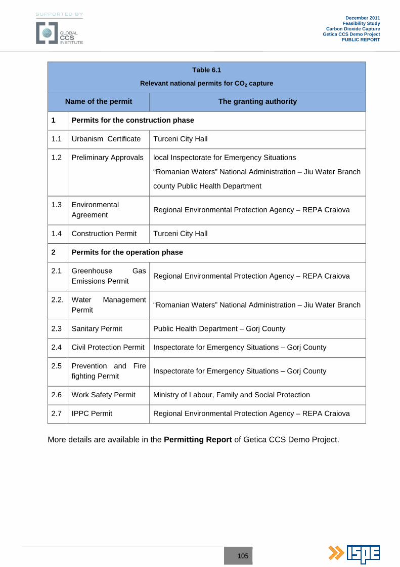
105
December 2011 Feasibility Study
Carbon Dioxide Capture Getica CCS Demo Project
PUBLIC REPORT
Table 6.1
Relevant national permits for CO 2 capture
Name of the permit The granting authority
1 Permits for the construction phase
1.1 Urbanism Certificate Turceni City Hall
1.2 Preliminary Approvals local Inspectorate for Emergency Situations
“Romanian Waters” National Administration – Jiu Water Branch
county Public Health Department
1.3 Environmental Agreement
Regional Environmental Protection Agency – REPA Craiova
1.4 Construction Permit Turceni City Hall
2 Permits for the operation phase
2.1 Greenhouse Gas Emissions Permit
Regional Environmental Protection Agency – REPA Craiova
2.2. Water Management Permit
“Romanian Waters” National Administration – Jiu Water Branch
2.3 Sanitary Permit Public Health Department – Gorj County
2.4 Civil Protection Permit Inspectorate for Emergency Situations – Gorj County
2.5 Prevention and Fire fighting Permit
Inspectorate for Emergency Situations – Gorj County
2.6 Work Safety Permit Ministry of Labour, Family and Social Protection
2.7 IPPC Permit Regional Environmental Protection Agency – REPA Craiova
More details are available in the Permitting Report of Getica CCS Demo Project.
106
December 2011 Feasibility Study
Carbon Dioxide Capture Getica CCS Demo Project
PUBLIC REPORT
7. CONCLUSIONS
Getica CCS Demo Project is a governmental demonstrative project, officially sustained by the Prime-Minister and coordinated by the Ministry of Economy, Trade and Business Environment and supported by the Global CCS Institute.
Getica CCS Demo Project is an integrated CCS project , comprising the full chain: capture, transport and storage of CO 2.
The project was selected following a national ranking process for CCS projects proposals, initiated by METBE, addressed to all major CO2 polluters in Romania.
The project is co-ordinated by an Inter-Ministerial Steering Committee established by METBE’s Order no 1508/2010 which includes representatives of METBE, MEF, MPF, NAMR, NASR, CE Turceni, SNTGN Transgaz, SNGN Romgaz.
The project will be implemented and operated by a new Project Company (PC) set up especially for this purpose.
The CO2 Capture Plant will be implemented in Turceni Power Plant, a base load power plant, one of the strategic electricity suppliers to the Romanian National Energy System.
The CO2 Capture Plant is fitted to one of the six existing power unit of Turceni Power Plant, which implies the development of solutions for integration.
Power Unit no. 6 is an existing one, fuelled by local lignite, and it will be retrofitted including Wet Flue Gases Desulphurization plant and dense slurry installation for ash and slag discharge.
Two technologies were compared, technically and economically: Chilled Ammonia Process (CAP) and the Advanced Amine Process (AAP), as they are the post-combustion CO2 capture technologies furthest in development and closest to commercialization.
For the specific operating condition of Unit no. 6, a CO2 Carbon Capture Plant based on the absorption of the CO2 from the flue gases was selected, using Alstom’s Chilled Ammonia Process (CAP).
The CCP will treat an equivalent flue gases flow of 250 MWe of gross electrical output (before capture) from Power Unit no. 6 WFGD exhaust.
The CCP interfaces directly with various systems of the Turceni Power Plant. Therefore, an integration approach to the project was of significant importance.
Special care was taken for the heat integration part by analysing five concepts, from which Concept 2 (IP-steam extraction at hot reheat line with downstream auxiliary
107
December 2011 Feasibility Study
Carbon Dioxide Capture Getica CCS Demo Project
PUBLIC REPORT
turbine /LP-steam extraction at IP/LP crossover pipe) was chosen due to its technical and economic benefits.
The scope of the Feasibility Study for the CO2 capture plant was to establish the following:
• Evaluate appropriate CCS Technology for the Getica CCS Demo project;
• Prepare the material balance and process concept (overall material balance and Block Flow Diagram);
• Prepare sized equipment list for cost estimate;
• Prepare consumption lists for electric power, cooling water, make-up water and chemicals;
• Prepare Electrical Line Diagram;
• Prepare cost estimate;
• Provide CCS – Power Plant integration concept, regarding steam extraction, condensate return, cooling water and potential other integration;
• Evaluate plot space requirement and feasibility of installation, supported by a 3D model and CCP layout;
• Provide preliminary construction execution plan and general operation description;
• Preliminary civil, structural and architectural engineering;
• High level instrumentation concept.
The Chilled Ammonia Process (CAP) offers the following advantages:
• Economically attractive, especially by the favourable site condition;
• It is not required to improve the existing efficiency of the EP and the WFGD, the values of PM and SO2 in the flue gases are proper for the chemical process;
• The stability of the ammonium solution is not affected by oxygen or acidic trace components present in the flue gases;
• Low cost and easily available bulk solvent on the market;
• Environmentally friendly (no degradation products, no complex chemical compounds, no impact on environment due to waste streams or gaseous emissions).